· pdf file · 2015-05-203gpp ts 29.060 v7.17.0 (2011-09) technical specification...
TRANSCRIPT

3GPP TS 29.060 V7.17.0 (2011-09) Technical Specification
3rd Generation Partnership Project; Technical Specification Group Core Network and Terminals;
General Packet Radio Service (GPRS); GPRS Tunnelling Protocol (GTP)
across the Gn and Gp interface (Release 7)
GLOBAL SYSTEM FOR
MOBILE COMMUNICATIONS
R
The present document has been developed within the 3rd Generation Partnership Project (3GPP TM) and may be further elaborated for the purposes of 3GPP.
The present document has not been subject to any approval process by the 3GPP Organisational Partners and shall not be implemented. This Specification is provided for future development work within 3GPP only. The Organisational Partners accept no liability for any use of this Specification.
Specifications and reports for implementation of the 3GPP TM system should be obtained via the 3GPP Organisational Partners' Publications Offices.
3GPP
3GPP TS 29.060 V7.17.0 (2011-09) 2 Release 7
Keywords
GSM, UMTS, packet mode, GPRS
3GPP
Postal address
3GPP support office address
650 Route des Lucioles - Sophia Antipolis Valbonne - FRANCE
Tel.: +33 4 92 94 42 00 Fax: +33 4 93 65 47 16
Internet
http://www.3gpp.org
Copyright Notification
No part may be reproduced except as authorized by written permission.
The copyright and the foregoing restriction extend to reproduction in all media.
© 2011, 3GPP Organizational Partners (ARIB, ATIS, CCSA, ETSI, TTA, TTC).
All rights reserved.
UMTS™ is a Trade Mark of ETSI registered for the benefit of its members
3GPP™ is a Trade Mark of ETSI registered for the benefit of its Members and of the 3GPP Organizational Partners
LTE™ is a Trade Mark of ETSI currently being registered for the benefit of its Members and of the 3GPP Organizational Partners
GSM® and the GSM logo are registered and owned by the GSM Association

3GPP
3GPP TS 29.060 V7.17.0 (2011-09) 3 Release 7
Contents
Foreword............................................................................................................................................................. 8
1 Scope ........................................................................................................................................................ 9
2 References ................................................................................................................................................ 9
3 Definitions and abbreviations ................................................................................................................. 10 3.1 Definitions ....................................................................................................................................................... 10 3.2 Abbreviations ................................................................................................................................................... 12
4 General ................................................................................................................................................... 12
5 Transmission Order and Bit Definitions ................................................................................................ 13
6 GTP Header ............................................................................................................................................ 14 6.1 Extension headers ............................................................................................................................................ 16 6.1.1 PDCP PDU Number ................................................................................................................................... 16 6.1.2 Suspend Request ........................................................................................................................................ 16 6.1.3 Suspend Response ...................................................................................................................................... 17 6.1.4 MBMS support indication .......................................................................................................................... 17 6.1.5 MS Info Change Reporting support indication .......................................................................................... 18
7 GTP Messages and Message Formats .................................................................................................... 18 7.1 Message Formats ............................................................................................................................................. 18 7.1.1 Presence requirements of Information Elements ........................................................................................ 20 7.2 Path Management Messages ............................................................................................................................ 20 7.2.1 Echo Request .............................................................................................................................................. 20 7.2.2 Echo Response ........................................................................................................................................... 21 7.2.3 Version Not Supported ............................................................................................................................... 21 7.2.4 Supported Extension Headers Notification ................................................................................................ 21 7.3 Tunnel Management Messages ........................................................................................................................ 21 7.3.1 Create PDP Context Request ...................................................................................................................... 21 7.3.2 Create PDP Context Response ................................................................................................................... 24 7.3.3 Update PDP Context Request..................................................................................................................... 27 7.3.4 Update PDP Context Response .................................................................................................................. 30 7.3.5 Delete PDP Context Request ...................................................................................................................... 34 7.3.6 Delete PDP Context Response ................................................................................................................... 35 7.3.7 Error Indication .......................................................................................................................................... 36 7.3.8 PDU Notification Request .......................................................................................................................... 36 7.3.9 PDU Notification Response ....................................................................................................................... 37 7.3.10 PDU Notification Reject Request............................................................................................................... 38 7.3.11 PDU Notification Reject Response ............................................................................................................ 39 7.3.12 Initiate PDP Context Activation Request ................................................................................................... 39 7.3.13 Initiate PDP Context Activation Response................................................................................................. 40 7.4 Location Management Messages ..................................................................................................................... 41 7.4.1 Send Routeing Information for GPRS Request .......................................................................................... 41 7.4.2 Send Routeing Information for GPRS Response ....................................................................................... 42 7.4.3 Failure Report Request ............................................................................................................................... 42 7.4.4 Failure Report Response ............................................................................................................................ 43 7.4.5 Note MS GPRS Present Request ................................................................................................................ 43 7.4.6 Note MS GPRS Present Response ............................................................................................................. 44 7.5 Mobility Management Messages ..................................................................................................................... 44 7.5.1 Identification Request ................................................................................................................................ 44 7.5.2 Identification Response .............................................................................................................................. 45 7.5.3 SGSN Context Request .............................................................................................................................. 46 7.5.4 SGSN Context Response ............................................................................................................................ 47 7.5.5 SGSN Context Acknowledge ..................................................................................................................... 49 7.5.6 Forward Relocation Request ...................................................................................................................... 49 7.5.7 Forward Relocation Response .................................................................................................................... 51 7.5.8 Forward Relocation Complete.................................................................................................................... 53
3GPP
3GPP TS 29.060 V7.17.0 (2011-09) 4 Release 7
7.5.9 Relocation Cancel Request ......................................................................................................................... 53 7.5.10 Relocation Cancel Response ...................................................................................................................... 53 7.5.11 Forward Relocation Complete Acknowledge ............................................................................................ 54 7.5.12 Forward SRNS Context Acknowledge ....................................................................................................... 54 7.5.13 Forward SRNS Context .............................................................................................................................. 54 7.5.14 RAN Information Management Messages ................................................................................................. 55 7.5.14.1 RAN Information Relay ....................................................................................................................... 55 7.5A MBMS Messages ............................................................................................................................................. 55 7.5A.1 UE Specific MBMS Messages ................................................................................................................... 56 7.5A.1.1 MBMS Notification Request ................................................................................................................ 56 7.5A.1.2 MBMS Notification Response .............................................................................................................. 56 7.5A.1.3 MBMS Notification Reject Request ..................................................................................................... 57 7.5A.1.4 MBMS Notification Reject Response .................................................................................................. 58 7.5A.1.5 Create MBMS Context Request ........................................................................................................... 58 7.5A.1.6 Create MBMS Context Response ......................................................................................................... 60 7.5A.1.7 Update MBMS Context Request .......................................................................................................... 62 7.5A.1.8 Update MBMS Context Response ........................................................................................................ 63 7.5A.1.9 Delete MBMS Context Request ........................................................................................................... 65 7.5A.1.10 Delete MBMS Context Response ......................................................................................................... 66 7.5A.2 Service Specific MBMS Messages ............................................................................................................ 67 7.5A.2.1 MBMS Registration Request ................................................................................................................ 67 7.5A.2.2 MBMS Registration Response ............................................................................................................. 68 7.5A.2.3 MBMS De-registration Request ........................................................................................................... 69 7.5A.2.4 MBMS De-Registration Response ....................................................................................................... 70 7.5A.2.5 MBMS Session Start Request ............................................................................................................... 70 7.5A.2.6 MBMS Session Start Response ............................................................................................................ 71 7.5A.2.7 MBMS Session Stop Request ............................................................................................................... 73 7.5A.2.8 MBMS Session Stop Response ............................................................................................................ 73 7.5A.2.9 MBMS Session Update Request ........................................................................................................... 74 7.5A.2.10 MBMS Session Update Response ........................................................................................................ 75 7.5B.1 MS Info Change Reporting Messages ............................................................................................................. 76 7.5B.1.1 MS Info Change Notification Request ............................................................................................................. 76 7.5B.1.2 MS Info Change Notification Response .......................................................................................................... 76 7.6 Reliable Delivery of Signalling Messages ....................................................................................................... 77 7.7 Information Elements ...................................................................................................................................... 78 7.7.1 Cause .......................................................................................................................................................... 80 7.7.2 International Mobile Subscriber Identity (IMSI)........................................................................................ 82 7.7.3 Routeing Area Identity (RAI)..................................................................................................................... 83 7.7.4 Temporary Logical Link Identity (TLLI) ................................................................................................... 83 7.7.5 Packet TMSI (P-TMSI) .............................................................................................................................. 84 7.7.6 Reordering Required .................................................................................................................................. 84 7.7.7 Authentication Triplet ................................................................................................................................ 84 7.7.8 MAP Cause ................................................................................................................................................ 85 7.7.9 P-TMSI Signature ...................................................................................................................................... 85 7.7.10 MS Validated ............................................................................................................................................. 85 7.7.11 Recovery .................................................................................................................................................... 85 7.7.12 Selection Mode ........................................................................................................................................... 86 7.7.13 Tunnel Endpoint Identifier Data I .............................................................................................................. 86 7.7.14 Tunnel Endpoint Identifier Control Plane .................................................................................................. 86 7.7.15 Tunnel Endpoint Identifier Data II ............................................................................................................. 87 7.7.16 Teardown Ind ............................................................................................................................................. 87 7.7.17 NSAPI ........................................................................................................................................................ 88 7.7.18 RANAP Cause ........................................................................................................................................... 88 7.7.19 RAB Context .............................................................................................................................................. 88 7.7.20 Radio Priority SMS .................................................................................................................................... 89 7.7.21 Radio Priority ............................................................................................................................................. 89 7.7.22 Packet Flow Id............................................................................................................................................ 89 7.7.23 Charging Characteristics ............................................................................................................................ 90 7.7.24 Trace Reference ......................................................................................................................................... 90 7.7.25 Trace Type ................................................................................................................................................. 90 7.7.25A MS Not Reachable Reason ......................................................................................................................... 91 7.7.25B Radio Priority LCS ..................................................................................................................................... 91
3GPP
3GPP TS 29.060 V7.17.0 (2011-09) 5 Release 7
7.7.26 Charging ID ................................................................................................................................................ 91 7.7.27 End User Address ....................................................................................................................................... 92 7.7.28 MM Context ............................................................................................................................................... 93 7.7.29 PDP Context ............................................................................................................................................... 96 7.7.30 Access Point Name .................................................................................................................................. 100 7.7.31 Protocol Configuration Options ............................................................................................................... 100 7.7.32 GSN Address ............................................................................................................................................ 100 7.7.33 MS International PSTN/ISDN Number (MSISDN) ................................................................................. 100 7.7.34 Quality of Service (QoS) Profile .............................................................................................................. 101 7.7.35 Authentication Quintuplet ........................................................................................................................ 102 7.7.36 Traffic Flow Template (TFT) ................................................................................................................... 102 7.7.37 Target Identification ................................................................................................................................. 103 7.7.38 UTRAN Transparent Container ............................................................................................................... 103 7.7.39 RAB Setup Information ........................................................................................................................... 103 7.7.40 Extension Header Type List ..................................................................................................................... 104 7.7.41 Trigger Id ................................................................................................................................................. 104 7.7.42 OMC Identity ........................................................................................................................................... 105 7.7.43 RAN Transparent Container ..................................................................................................................... 105 7.7.44 Charging Gateway Address ...................................................................................................................... 105 7.7.45 PDP Context Prioritization ....................................................................................................................... 106 7.7.45A Additional RAB Setup Information ......................................................................................................... 106 7.7.46 Private Extension ..................................................................................................................................... 106 7.7.47 SGSN Number ......................................................................................................................................... 107 7.7.48 Common Flags ......................................................................................................................................... 107 7.7.49 APN Restriction ....................................................................................................................................... 108 7.7.50 RAT Type ................................................................................................................................................ 108 7.7.51 User Location Information ....................................................................................................................... 109 7.7.52 MS Time Zone ......................................................................................................................................... 110 7.7.53 International Mobile Equipment Identity (and Software Version) (IMEI(SV)) ....................................... 111 7.7.54 CAMEL Charging Information Container ............................................................................................... 111 7.7.55 MBMS UE Context .................................................................................................................................. 112 7.7.56 Temporary Mobile Group Identity ........................................................................................................... 113 7.7.57 RIM Routing Address .............................................................................................................................. 113 7.7.58 MBMS Protocol Configuration Options .................................................................................................. 114 7.7.59 MBMS Session Duration ......................................................................................................................... 114 7.7.60 MBMS Service Area ................................................................................................................................ 114 7.7.61 Source RNC PDCP context info .............................................................................................................. 114 7.7.62 Additional Trace Info ............................................................................................................................... 115 7.7.63 Hop Counter ............................................................................................................................................. 115 7.7.64 Selected PLMN ID ................................................................................................................................... 116 7.7.65 MBMS Session Identifier ......................................................................................................................... 116 7.7.66 MBMS 2G/3G Indicator ........................................................................................................................... 116 7.7.67 Enhanced NSAPI ..................................................................................................................................... 117 7.7.68 Additional MBMS Trace Info .................................................................................................................. 117 7.7.69 MBMS Session Repetition Number ......................................................................................................... 118 7.7.70 MBMS Time To Data Transfer ................................................................................................................ 118 7.7.71 Void .......................................................................................................................................................... 118 7.7.72 BSS Container .......................................................................................................................................... 118 7.7.73 Cell Identification ..................................................................................................................................... 119 7.7.74 PDU Numbers .......................................................................................................................................... 119 7.7.75 BSSGP Cause ........................................................................................................................................... 120 7.7.76 Required MBMS Bearer Capabilities ....................................................................................................... 120 7.7.77 RIM Routing Address Discriminator ....................................................................................................... 120 7.7.78 List of set-up PFCs ................................................................................................................................... 121 7.7.79 PS Handover XID Parameters .................................................................................................................. 121 7.7.80 MS Info Change Reporting Action .......................................................................................................... 122 7.7.81 Direct Tunnel Flags .................................................................................................................................. 122 7.7.82 Correlation-ID .......................................................................................................................................... 123 7.7.83 Bearer Control Mode ................................................................................................................................ 123 7.7.84 Reliable INTER RAT HANDOVER INFO ............................................................................................. 123
8 Control Plane (GTP-C)......................................................................................................................... 124
3GPP
3GPP TS 29.060 V7.17.0 (2011-09) 6 Release 7
8.1 Control Plane Protocol ................................................................................................................................... 124 8.2 Usage of the GTP-C Header .......................................................................................................................... 124
9 GTP-U .................................................................................................................................................. 126 9.1 GTP-U Protocol Entity .................................................................................................................................. 126 9.1.1 Handling of Sequence Numbers ............................................................................................................... 126 9.2 GTP-U Service Access Points and Primitives ............................................................................................... 126 9.2.1 GTP-U-CONTROL SAP .......................................................................................................................... 127 9.2.1.1 GTP-U-CONTROL-RX primitives .................................................................................................... 127 9.2.1.1.1 GTP-U-CONTROL-RX-SETUP.request ...................................................................................... 127 9.2.1.1.2 GTP-U-CONTROL-RX-SETUP.confirm ..................................................................................... 127 9.2.1.1.3 GTP-U-CONTROL-RX-RELEASE.request................................................................................. 127 9.2.1.1.4 GTP-U-CONTROL-RX-RELEASE.confirm ............................................................................... 127 9.2.1.1.5 GTP-U-CONTROL-RX-ERROR.indication ................................................................................ 128 9.2.1.2 GTP-U-CONTROL-TX primitives .................................................................................................... 128 9.2.1.2.1 GTP-U-CONTROL-TX-SETUP.request ...................................................................................... 128 9.2.1.2.2 GTP-U-CONTROL-TX-SETUP.confirm ..................................................................................... 128 9.2.1.2.3 GTP-U-CONTROL-TX-RELEASE.request ................................................................................. 128 9.2.1.2.4 GTP-U-CONTROL-TX-RELEASE.confirm ................................................................................ 128 9.2.1.2.5 GTP-U-CONTROL-TX-ERROR.indication................................................................................. 128 9.2.2 GTP-U-UNIT-DATA SAP and Primitives .............................................................................................. 128 9.2.2.1 GTP-U-UNIT-DATA.request ............................................................................................................. 129 9.2.2.2 GTP-U- UNIT-DATA.indication ....................................................................................................... 129 9.3 Protocol Stack ................................................................................................................................................ 129 9.3.1 Usage of the GTP-U Header .................................................................................................................... 129 9.3.1.1 Usage of Sequence Number ............................................................................................................... 130 9.4 Tunnelling between SGSNs ........................................................................................................................... 130 9.5 Tunnelling between Source RNC and Target RNC ....................................................................................... 130 9.6 Tunnelling between GGSNs .......................................................................................................................... 131
10 Path Protocols ....................................................................................................................................... 131 10.1 UDP/IP ........................................................................................................................................................... 131 10.1.1 UDP Header ............................................................................................................................................. 131 10.1.1.1 Request Messages ............................................................................................................................... 131 10.1.1.2 Response Messages ............................................................................................................................ 131 10.1.1.3 Encapsulated T-PDUs......................................................................................................................... 131 10.1.1.4 Error Indication, RAN Information Relay, Version Not Supported and Supported Extension
Headers Notification ........................................................................................................................... 131 10.1.2 IP Header .................................................................................................................................................. 131 10.1.2.1 Request Messages and Encapsulated T-PDUs .................................................................................... 131 10.1.2.2 Response Messages ............................................................................................................................ 132 10.1.2.3 Error Indication, RAN Information Relay, Version Not supported and Supported Extension
Headers Notification ........................................................................................................................... 132
11 Error Handling ..................................................................................................................................... 132 11.1 Protocol Errors ............................................................................................................................................... 132 11.1.1 Different GTP Versions ........................................................................................................................... 132 11.1.2 GTP Message Too Short .......................................................................................................................... 133 11.1.3 Unknown GTP Signalling Message ......................................................................................................... 133 11.1.4 Unexpected GTP Signalling Message ...................................................................................................... 133 11.1.5 Missing Mandatorily Present Information Element ................................................................................. 133 11.1.6 Invalid Length .......................................................................................................................................... 133 11.1.7 Invalid Mandatory Information Element .................................................................................................. 133 11.1.8 Invalid Optional Information Element ..................................................................................................... 133 11.1.9 Unknown Information Element ................................................................................................................ 134 11.1.10 Out of Sequence Information Elements ................................................................................................... 134 11.1.11 Unexpected Information Element ............................................................................................................ 134 11.1.12 Repeated Information Elements ............................................................................................................... 134 11.1.13 Incorrect Optional Information Elements ................................................................................................. 134 11.2 Path Failure .................................................................................................................................................... 134 11.3 MS Detach ..................................................................................................................................................... 134 11.4 Restoration and Recovery .............................................................................................................................. 134
3GPP
3GPP TS 29.060 V7.17.0 (2011-09) 7 Release 7
12 Security provided to GTP Communication over Gn and Gp Interfaces ............................................... 135
13 IP, The Networking Technology used by GTP .................................................................................... 135 13.1 IP Version ...................................................................................................................................................... 135 13.2 IP Fragmentation ........................................................................................................................................... 135 13.2.1 MO Direction ........................................................................................................................................... 135 13.2.2 MT Direction ............................................................................................................................................ 135 13.2.3 Tunnelling from old to new SGSN ........................................................................................................... 136
14 GTP Parameters.................................................................................................................................... 136 14.1 Timers ............................................................................................................................................................ 136 14.2 Others ............................................................................................................................................................. 136
15 Mapping of BSSGP and RANAP causes ............................................................................................. 136
Annex A (informative): A method for sequence number checking .................................................. 139
Annex B (informative): Change history ............................................................................................. 140

3GPP
3GPP TS 29.060 V7.17.0 (2011-09) 8 Release 7
Foreword
This Technical Specification (TS) has been produced by the 3rd
Generation Partnership Project (3GPP).
The present document defines the Gn and Gp interfaces for the General Packet Radio Service (GPRS) within the 3GPP
system.
The contents of the present document are subject to continuing work within the TSG and may change following formal
TSG approval. Should the TSG modify the contents of the present document, it will be re-released by the TSG with an
identifying change of release date and an increase in version number as follows:
Version x.y.z
where:
x the first digit:
1 presented to TSG for information;
2 presented to TSG for approval;
3 or greater indicates TSG approved document under change control.
y the second digit is incremented for all changes of substance, i.e. technical enhancements, corrections,
updates, etc.
z the third digit is incremented when editorial only changes have been incorporated in the document.
3GPP
3GPP TS 29.060 V7.17.0 (2011-09) 9 Release 7
1 Scope
The present document defines the second version of GTP used on:
the Gn and Gp interfaces of the General Packet Radio Service (GPRS);
the Iu, Gn and Gp interfaces of the UMTS system.
NOTE: The version number used in the message headers is 0 for the first version of GTP described in
GSM 09.60, and 1 for the second version in 3GPP TS 29.060.
2 References
The following documents contain provisions which, through reference in this text, constitute provisions of the present
document.
References are either specific (identified by date of publication, edition number, version number, etc.) or
non-specific.
For a specific reference, subsequent revisions do not apply.
For a non-specific reference, the latest version applies. In the case of a reference to a 3GPP document (including
a GSM document), a non-specific reference implicitly refers to the latest version of that document in the same
Release as the present document.
[1] 3GPP TR 21.905: "Vocabulary for 3GPP Specifications".
[2] 3GPP TS 23.003: "Numbering, addressing and identification".
[3] 3GPP TS 23.007: "Restoration procedures".
[4] 3GPP TS 23.060: "General Packet Radio Service (GPRS); Service description; Stage 2".
[5] 3GPP TS 24.008: "Mobile radio interface Layer 3 specification; Core network protocols; Stage 3".
[6] 3GPP TS 29.002: "Mobile Application Part (MAP) specification".
[7] 3GPP TS 25.413: "UTRAN Iu interface RANAP signalling".
[8] 3GPP TS 33.102: "3G security; Security architecture".
[9] 3GPP TS 43.020: " Security related network functions".
[10] 3GPP TS 43.064: "Overall description of the GPRS radio interface; Stage 2".
[11] 3GPP TS 44.064: "Mobile Station - Serving GPRS Support Node (MS-SGSN) Logical Link
Control (LLC) layer specification".
[12] IETF RFC 791 (STD 0005): "Internet Protocol", J. Postel.
[13] IETF RFC 768 (STD 0006): "User Datagram Protocol", J. Postel.
[14] IETF RFC 1700: "Assigned numbers", J. Reynolds and J. Postel.
[15] IETF RFC 2181: "Clarifications to the DNS specification", R. Elz and R. Bush.
[16] Void.
[17] 3GPP TS 23.121: "Architectural requirements for Release 1999".
[18] 3GPP TS 32.251: "Telecommunication management; Charging management; Packet Switched
(PS) domain charging".
3GPP
3GPP TS 29.060 V7.17.0 (2011-09) 10 Release 7
[19] 3GPP TS 23.236: "Intra domain connection of Radio Access Network (RAN) nodes to multiple
Core Network (CN) nodes".
[20] 3GPP TS 48.018: "General Packet Radio Service (GPRS); Base Station System (BSS) - Serving
GPRS Support Node (SGSN); BSS GPRS protocol".
[21] 3GPP TR 44.901 (Release 5): "External Network Assisted Cell Change (NACC)".
[22] 3GPP TS 33.210: "3G security; Network Domain Security (NDS); IP network layer security".
[23] 3GPP TS 25.414: "UTRAN Iu interface data transport and transport signalling".
[24] 3GPP TS 23.271: " Technical Specification Group Services and System Aspects; Functional stage
2 description of LCS".
[25] 3GPP TS 23.195: "Provision of User Equipment Specific Behaviour Information (UESBI) to
network entities".
[26] 3GPP TS23.246: "Multimedia Broadcast/Multicast Service (MBMS) Architecture and Functional
Description".
[27] 3GPP TS29.061: "Interworking beween the Public Land Mobile Network (PLMN) supporting
Packet Based Services and Packet Data Networks (PDN) "
[28] 3GPP TS 23.040: "Technical realization of the Short Message Service (SMS)".
[29] 3GPP TS 22.101: "Service Principles".
[30] 3GPP TS 32.421: "Subscriber and equipment trace: Trace concepts and requirements".
[31] 3GPP TS 32.422: "Subscriber and equipment trace: Trace Control and Configuration
Management".
[32] 3GPP TS 32.423: "Subscriber and equipment trace: Trace data definition and management".
[33] 3GPP TS 32.295: "Telecommunication management; Charging management; Charging Data
Record (CDR) transfer".
[34] 3GPP TS 32.298: "Telecommunication management; Charging management; Charging Data
Record (CDR) parameter description".
[35] 3GPP TS 23.251: "Network Sharing; Architecture and Functional Description".
[36] IETF RFC 3588: "Diameter Base Protocol"
[37] 3GPP TS 43.129: " Packet-switched handover for GERAN A/Gb mode; Stage 2".
[38] 3GPP TS 44.065: "Mobile Station (MS) - Serving GPRS Support Node (SGSN);Subnetwork
Dependent Convergence Protocol (SNDCP)".
[39] 3GPP TS 23.203: "Policy and charging control architecture; Stage 2".
[40] 3GPP TR 25.999: " HSPA Evolution (FDD)".
3 Definitions and abbreviations
3.1 Definitions
For the purposes of the present document, the following terms and definitions apply:
Enhanced Network Service Access Point Identifier (Enhanced NSAPI): integer value in the range [128; 255],
identifying a certain Multimedia Broadcast/Multicast Service (MBMS) UE Context. G-PDU: is a user data message, It
consists of a T-PDU plus a GTP header
3GPP
3GPP TS 29.060 V7.17.0 (2011-09) 11 Release 7
GTP Tunnel: in the GTP-U plane is defined for each PDP Context or each MBMS service in the GSNs and/or each
RAB in the RNC. A GTP tunnel in the GTP-C plane is defined for all PDP Contexts with the same PDP address and
APN (for Tunnel Management messages and UE Specific MBMS message), for each MBMS service (for Service
Specific MBMS messages) or for each MS (for other types of messages). A GTP tunnel is identified in each node with a
TEID, an IP address and a UDP port number. A GTP tunnel is necessary to forward packets between an external packet
data network and an MS user.
MBMS Bearer Context: contains all information describing a particular MBMS bearer service.
MBMS UE Context: contains UE-specific information related to a particular MBMS service that the UE has joined.
MM Context: information sets held in MS and GSNs for a GPRS subscriber related to Mobility Management (MM)
(please refer to the MM Context Information Element)
Network Service Access Point Identifier (NSAPI): integer value in the range [0; 15], identifying a certain PDP
Context. It identifies a PDP context belonging to a specific MM Context ID
path: UDP/IP path is used to multiplex GTP tunnels
Path Protocol: protocol used as a bearer of GTP between GSNs or between a GSN and a RNC
Packet Data Protocol (PDP): network protocol used by an external packet data network interfacing to GPRS
PDP Context: information sets held in MS and GSNs for a PDP address (please refer to the PDP Context Information
Element)
PS Handover procedure: used to enable MS with one or more packet flows to be moved between two cells with
minimal service interruption through allocation of radio resources in the target cell while the MS is still in the source
cell.
PS Handover XID Parameters: contains LLC XID parameters (with SNDCP XID parameters contained within) that
need to be transferred between SGSNs during the PS handover procedure.
Quality of Service (QoS): may be applicable for the GPRS backbone and the Iu interface if the path media supports it
Separate paths with different priorities may be defined between a GSN pair or between a GSN and an RNC.
GTP-C Message: GTP-C or control plane messages are exchanged between GSN/RNC pairs in a path
The control plane messages are used to transfer GSN capability information between GSN pairs, to create, update and
delete GTP tunnels and for path management.
GTP-U Message: GTP-U or user plane messages are exchanged between GSN pairs or GSN/RNC pairs in a path
The user plane messages are used to carry user data packets, and signalling messages for path management and error
indication.
GTP-PDU: GTP Protocol Data Unit is either a GTP-C message or a GTP-U message
Signalling Message: any GTP-PDU except the G-PDU
T-PDU: original packet, for example an IP datagram, from an MS or a network node in an external packet data network
A T-PDU is the payload that is tunnelled in the GTP-U tunnel.
Traffic Flow Template (TFTs): used by GGSN to distinguish between different user payload packets and transmit
packets with different QoS requirements via different PDP context but to the same PDP address
Tunnel Endpoint IDentifier (TEID): unambiguously identifies a tunnel endpoint in the receiving GTP-U or GTP-C
protocol entity
The receiving end side of a GTP tunnel locally assigns the TEID value the transmitting side has to use. The TEID
values are exchanged between tunnel endpoints using GTP-C (or RANAP, over the Iu) messages.
UDP/IP Path: connection-less unidirectional or bidirectional path defined by two end-points
An IP address and a UDP port number define an end-point. A UDP/IP path carries GTP messages between GSN nodes,
and between GSN and RNC nodes related to one or more GTP tunnels.
3GPP
3GPP TS 29.060 V7.17.0 (2011-09) 12 Release 7
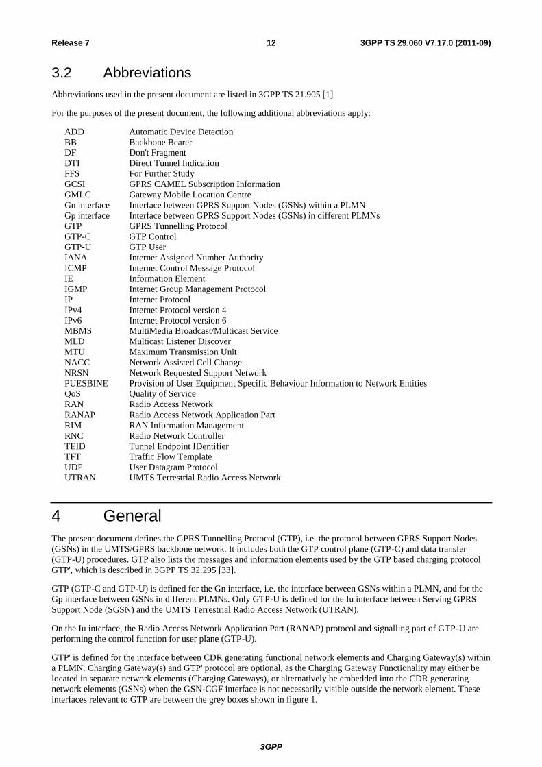
3.2 Abbreviations
Abbreviations used in the present document are listed in 3GPP TS 21.905 [1]
For the purposes of the present document, the following additional abbreviations apply:
ADD Automatic Device Detection
BB Backbone Bearer
DF Don't Fragment
DTI Direct Tunnel Indication
FFS For Further Study
GCSI GPRS CAMEL Subscription Information
GMLC Gateway Mobile Location Centre
Gn interface Interface between GPRS Support Nodes (GSNs) within a PLMN
Gp interface Interface between GPRS Support Nodes (GSNs) in different PLMNs
GTP GPRS Tunnelling Protocol
GTP-C GTP Control
GTP-U GTP User
IANA Internet Assigned Number Authority
ICMP Internet Control Message Protocol
IE Information Element
IGMP Internet Group Management Protocol
IP Internet Protocol
IPv4 Internet Protocol version 4
IPv6 Internet Protocol version 6
MBMS MultiMedia Broadcast/Multicast Service
MLD Multicast Listener Discover
MTU Maximum Transmission Unit
NACC Network Assisted Cell Change
NRSN Network Requested Support Network
PUESBINE Provision of User Equipment Specific Behaviour Information to Network Entities
QoS Quality of Service
RAN Radio Access Network
RANAP Radio Access Network Application Part
RIM RAN Information Management
RNC Radio Network Controller
TEID Tunnel Endpoint IDentifier
TFT Traffic Flow Template
UDP User Datagram Protocol
UTRAN UMTS Terrestrial Radio Access Network
4 General
The present document defines the GPRS Tunnelling Protocol (GTP), i.e. the protocol between GPRS Support Nodes
(GSNs) in the UMTS/GPRS backbone network. It includes both the GTP control plane (GTP-C) and data transfer
(GTP-U) procedures. GTP also lists the messages and information elements used by the GTP based charging protocol
GTP', which is described in 3GPP TS 32.295 [33].
GTP (GTP-C and GTP-U) is defined for the Gn interface, i.e. the interface between GSNs within a PLMN, and for the
Gp interface between GSNs in different PLMNs. Only GTP-U is defined for the Iu interface between Serving GPRS
Support Node (SGSN) and the UMTS Terrestrial Radio Access Network (UTRAN).
On the Iu interface, the Radio Access Network Application Part (RANAP) protocol and signalling part of GTP-U are
performing the control function for user plane (GTP-U).
GTP' is defined for the interface between CDR generating functional network elements and Charging Gateway(s) within
a PLMN. Charging Gateway(s) and GTP' protocol are optional, as the Charging Gateway Functionality may either be
located in separate network elements (Charging Gateways), or alternatively be embedded into the CDR generating
network elements (GSNs) when the GSN-CGF interface is not necessarily visible outside the network element. These
interfaces relevant to GTP are between the grey boxes shown in figure 1.

3GPP
3GPP TS 29.060 V7.17.0 (2011-09) 13 Release 7
Gi Gn
Gc
Gp
Signalling and Data Transfer
Interface
Signalling Interface
TE PDN
Iu
UTRAN TE MT
Gr or Gc
HLR
Other PLMN
SGSN GGSN
SGSN
GTP-MAP protocol
converting GSN
Gn
Iu
TE MT UTRAN
SGSN
Gn
BSS
Gb
TE MT
Gn
Figure 1: GPRS Logical Architecture with interface name denotations
GTP allows multi-protocol packets to be tunnelled through the UMTS/GPRS Backbone between GSNs and between
SGSN and UTRAN.
In the control plane, GTP specifies a tunnel control and management protocol (GTP-C) which allows the SGSN to
provide packet data network access for an MS. Control Plane signalling is used to create, modify and delete tunnels.
GTP also allows creation, and deletion of a single multicast service tunnel, that can be used for delivering packets to all
the users who have joined a particular multicast service.
In the user plane, GTP uses a tunnelling mechanism (GTP-U) to provide a service for carrying user data packets.
The GTP-U protocol is implemented by SGSNs and GGSNs in the UMTS/GPRS Backbone and by Radio Network
Controllers (RNCs) in the UTRAN. SGSNs and GGSNs in the UMTS/GPRS Backbone implement the GTP-C protocol.
No other systems need to be aware of GTP. UMTS/GPRS MSs are connected to an SGSN without being aware of GTP.
It is assumed that there will be a many-to-many relationship between SGSNs and GGSNs. A SGSN may provide
service to many GGSNs. A single GGSN may associate with many SGSNs to deliver traffic to a large number of
geographically diverse mobile stations.
SGSN and GGSN implementing GTP protocol version 1 should be able to fallback to GTP protocol version 0. All
GSNs should be able to support all earlier GTP versions.
5 Transmission Order and Bit Definitions
The messages in this document shall be transmitted in network octet order starting with octet 1. Where information
elements are repeated within a message the order shall be determined by the order of appearance in the table defining
the information elements in the message.
The most significant bit of an octet in a GTP message is bit 8. If a value in a GTP message spans several octets and
nothing else is stated, the most significant bit is bit 8 of the octet with the lowest number.
3GPP
3GPP TS 29.060 V7.17.0 (2011-09) 14 Release 7
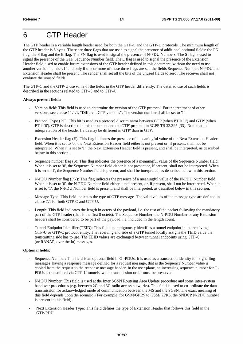
6 GTP Header
The GTP header is a variable length header used for both the GTP-C and the GTP-U protocols. The minimum length of
the GTP header is 8 bytes. There are three flags that are used to signal the presence of additional optional fields: the PN
flag, the S flag and the E flag. The PN flag is used to signal the presence of N-PDU Numbers. The S flag is used to
signal the presence of the GTP Sequence Number field. The E flag is used to signal the presence of the Extension
Header field, used to enable future extensions of the GTP header defined in this document, without the need to use
another version number. If and only if one or more of these three flags are set, the fields Sequence Number, N-PDU and
Extension Header shall be present. The sender shall set all the bits of the unused fields to zero. The receiver shall not
evaluate the unused fields.
The GTP-C and the GTP-U use some of the fields in the GTP header differently. The detailed use of such fields is
described in the sections related to GTP-C and to GTP-U.
Always present fields:
- Version field: This field is used to determine the version of the GTP protocol. For the treatment of other
versions, see clause 11.1.1, "Different GTP versions". The version number shall be set to '1'.
- Protocol Type (PT): This bit is used as a protocol discriminator between GTP (when PT is '1') and GTP' (when
PT is '0'). GTP is described in this document and the GTP' protocol in 3GPP TS 32.295 [33]. Note that the
interpretation of the header fields may be different in GTP' than in GTP.
- Extension Header flag (E): This flag indicates the presence of a meaningful value of the Next Extension Header
field. When it is set to '0', the Next Extension Header field either is not present or, if present, shall not be
interpreted. When it is set to '1', the Next Extension Header field is present, and shall be interpreted, as described
below in this section.
- Sequence number flag (S): This flag indicates the presence of a meaningful value of the Sequence Number field.
When it is set to '0', the Sequence Number field either is not present or, if present, shall not be interpreted. When
it is set to '1', the Sequence Number field is present, and shall be interpreted, as described below in this section.
- N-PDU Number flag (PN): This flag indicates the presence of a meaningful value of the N-PDU Number field.
When it is set to '0', the N-PDU Number field either is not present, or, if present, shall not be interpreted. When it
is set to '1', the N-PDU Number field is present, and shall be interpreted, as described below in this section.
- Message Type: This field indicates the type of GTP message. The valid values of the message type are defined in
clause 7.1 for both GTP-C and GTP-U.
- Length: This field indicates the length in octets of the payload, i.e. the rest of the packet following the mandatory
part of the GTP header (that is the first 8 octets). The Sequence Number, the N-PDU Number or any Extension
headers shall be considered to be part of the payload, i.e. included in the length count.
- Tunnel Endpoint Identifier (TEID): This field unambiguously identifies a tunnel endpoint in the receiving
GTP-U or GTP-C protocol entity. The receiving end side of a GTP tunnel locally assigns the TEID value the
transmitting side has to use. The TEID values are exchanged between tunnel endpoints using GTP-C
(or RANAP, over the Iu) messages.
Optional fields:
- Sequence Number: This field is an optional field in G -PDUs. It is used as a transaction identity for signalling
messages having a response message defined for a request message, that is the Sequence Number value is
copied from the request to the response message header. In the user plane, an increasing sequence number for T-
PDUs is transmitted via GTP-U tunnels, when transmission order must be preserved.
- N-PDU Number: This field is used at the Inter SGSN Routeing Area Update procedure and some inter-system
handover procedures (e.g. between 2G and 3G radio access networks). This field is used to co-ordinate the data
transmission for acknowledged mode of communication between the MS and the SGSN. The exact meaning of
this field depends upon the scenario. (For example, for GSM/GPRS to GSM/GPRS, the SNDCP N-PDU number
is present in this field).
- Next Extension Header Type: This field defines the type of Extension Header that follows this field in the
GTP-PDU.

3GPP
3GPP TS 29.060 V7.17.0 (2011-09) 15 Release 7
Bits Octets 8 7 6 5 4 3 2 1
1 Version PT (*) E S PN
2 Message Type
3 Length (1st Octet)
4 Length (2nd
Octet)
5 Tunnel Endpoint Identifier (1st Octet)
6 Tunnel Endpoint Identifier (2nd
Octet)
7 Tunnel Endpoint Identifier (3rd
Octet)
8 Tunnel Endpoint Identifier (4th
Octet)
9 Sequence Number (1st Octet)
1) 4)
10 Sequence Number (2nd
Octet)1)
4)
11 N-PDU Number2) 4)
12 Next Extension Header Type3) 4)
NOTE 0: (*) This bit is a spare bit. It shall be sent as '0'. The receiver shall not evaluate this bit. NOTE 1: 1) This field shall only be evaluated when indicated by the S flag set to 1. NOTE 2: 2) This field shall only be evaluated when indicated by the PN flag set to 1. NOTE 3: 3) This field shall only be evaluated when indicated by the E flag set to 1. NOTE 4: 4) This field shall be present if and only if any one or more of the S, PN and E flags are set.
Figure 2: Outline of the GTP Header
The format of GTP Extension Headers is depicted in figure 2. The Extension Header Length field specifies the length of
the particular Extension header in 4 octets units. The Next Extension Header Type field specifies the type of any
Extension Header that may follow a particular Extension Header. If no such Header follows, then the value of the Next
Extension Header Type shall be 0.
Octets 1 Extension Header Length
2 - m Extension Header Content
m+1 Next Extension Header Type (note)
NOTE: The value of this field is 0 if no other Extension header follows.
Figure 3: Outline of the Extension Header Format
The length of the Extension header shall be defined in a variable length of 4 octets, i.e. m+1 = n*4 octets, where n is a
positive integer.
Bits 7 and 8 of the Next Extension Header Type define how the recipient shall handle unknown Extension Types. The
recipient of an extension header of unknown type but marked as 'comprehension not required' for that recipient shall
read the 'Next Extension Header Type' field (using the Extension Header Length field to identify its location in the
GTP-PDU).
The recipient of an extension header of unknown type but marked as 'comprehension required' for that recipient shall:
- If the message with the unknown extension header was a request, send a response message back with CAUSE set
to "unknown mandatory extension header".
- Send a Supported Extension Headers Notification to the originator of the GTP PDU.
- Log an error.
3GPP
3GPP TS 29.060 V7.17.0 (2011-09) 16 Release 7
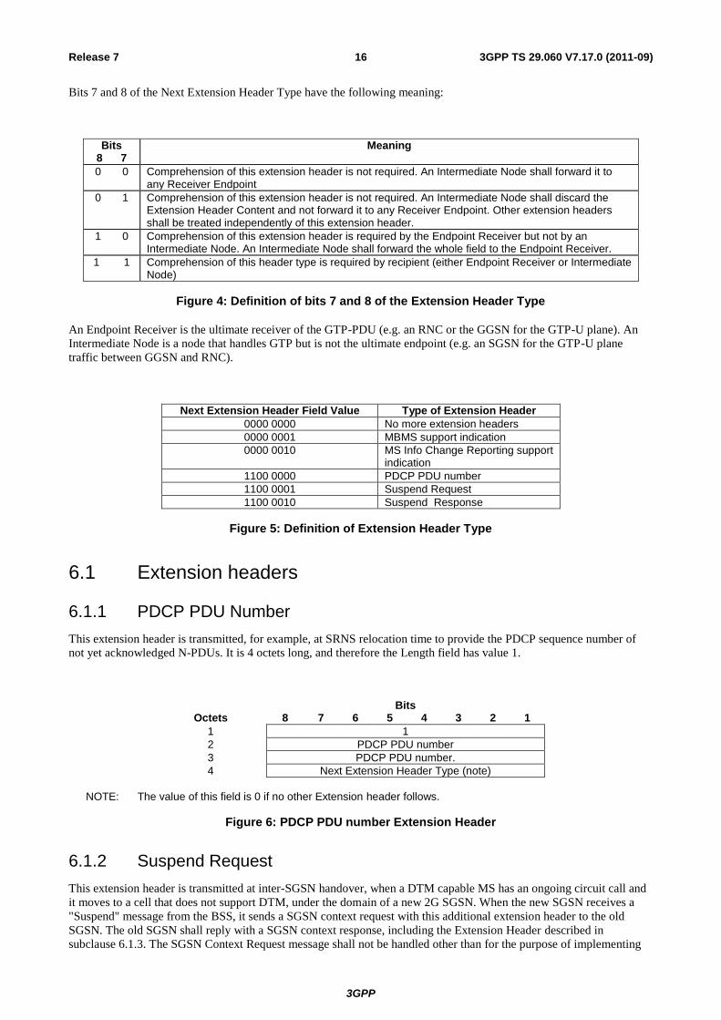
Bits 7 and 8 of the Next Extension Header Type have the following meaning:
Bits 8 7
Meaning
0 0 Comprehension of this extension header is not required. An Intermediate Node shall forward it to any Receiver Endpoint
0 1 Comprehension of this extension header is not required. An Intermediate Node shall discard the Extension Header Content and not forward it to any Receiver Endpoint. Other extension headers shall be treated independently of this extension header.
1 0 Comprehension of this extension header is required by the Endpoint Receiver but not by an Intermediate Node. An Intermediate Node shall forward the whole field to the Endpoint Receiver.
1 1 Comprehension of this header type is required by recipient (either Endpoint Receiver or Intermediate Node)
Figure 4: Definition of bits 7 and 8 of the Extension Header Type
An Endpoint Receiver is the ultimate receiver of the GTP-PDU (e.g. an RNC or the GGSN for the GTP-U plane). An
Intermediate Node is a node that handles GTP but is not the ultimate endpoint (e.g. an SGSN for the GTP-U plane
traffic between GGSN and RNC).
Next Extension Header Field Value Type of Extension Header
0000 0000 No more extension headers
0000 0001 MBMS support indication
0000 0010 MS Info Change Reporting support indication
1100 0000 PDCP PDU number
1100 0001 Suspend Request
1100 0010 Suspend Response
Figure 5: Definition of Extension Header Type
6.1 Extension headers
6.1.1 PDCP PDU Number
This extension header is transmitted, for example, at SRNS relocation time to provide the PDCP sequence number of
not yet acknowledged N-PDUs. It is 4 octets long, and therefore the Length field has value 1.
Bits Octets 8 7 6 5 4 3 2 1
1 1
2 PDCP PDU number
3 PDCP PDU number.
4 Next Extension Header Type (note)
NOTE: The value of this field is 0 if no other Extension header follows.
Figure 6: PDCP PDU number Extension Header
6.1.2 Suspend Request
This extension header is transmitted at inter-SGSN handover, when a DTM capable MS has an ongoing circuit call and
it moves to a cell that does not support DTM, under the domain of a new 2G SGSN. When the new SGSN receives a
"Suspend" message from the BSS, it sends a SGSN context request with this additional extension header to the old
SGSN. The old SGSN shall reply with a SGSN context response, including the Extension Header described in
subclause 6.1.3. The SGSN Context Request message shall not be handled other than for the purpose of implementing

3GPP
3GPP TS 29.060 V7.17.0 (2011-09) 17 Release 7
the Suspend functionality as described in 3GPP TS 23.060 [4]. The "SGSN context request" message shall not include
the "IMSI", "packet-TMSI" and "MS validated" IEs.
Bits Octets 8 7 6 5 4 3 2 1
1 1
2 0xFF
3 0xFF
4 Next Extension Header Type (note)
NOTE: The value of this field is 0 if no other Extension header follows.
Figure 7: Suspend Request Extension Header
6.1.3 Suspend Response
When a SGSN receives a SGSN Context Request with the extension header "Suspend Request" described in
subclause 6.1.2, it shall perform the actions specified in 3GPP TS 23.060 [4] and it shall return a SGSN Context
Response with this extension header included. The SGSN Context Response message shall not be handled other than
for the purpose of implementing the Suspend functionality as described in 3GPP TS 23.060 [4]. The "SGSN context
response" shall not include the "IMSI", "Radio priority SMS", "Radio priority", "packet flow ID", "MM context", "PDP
context" and "SGSN Address for control plane" IEs.
Bits Octets 8 7 6 5 4 3 2 1
1 1
2 0xFF
3 0xFF
4 Next Extension Header Type (note)
NOTE: The value of this field is 0 if no other Extension header follows.
Figure 8: Suspend Response Extension Header
6.1.4 MBMS support indication
This Extension Header shall be included by an SGSN supporting MBMS in all Create PDP Context Request messages
Update PDP Context Request messages, SGSN Context Request messages and Forward Relocation Response messages.
A GGSNsupporting MBMS receiving this Extension Header in a Create PDP Context Request or in an Update PDP
Context Request shall assume the SGSN originating the message supports MBMS in the handling of all subsequent
MBMS-related procedures. If this Extension Header is not received in a Create PDP Context Request or in an Update
PDP Context Request, then the GGSN shall assume that the SGSN originating the message does not support MBMS in
the handling of all subsequent MBMS-related procedures.
An SGSN supporting MBMS receiving this Extension Header in an SGSN Context Request or in a Forward Relocation
Response shall assume the SGSN originating the message supports MBMS in the handling of all subsequent MBMS-
related procedures. If this Extension Header is not received in a SGSN Context Request or in a Forward Relocation
Response, then the receiving SGSN shall deactivate the associated MBMS UE Contexts.

3GPP
3GPP TS 29.060 V7.17.0 (2011-09) 18 Release 7
Bits Octets 8 7 6 5 4 3 2 1
1 1
2 0xFF
3 0xFF
4 Next Extension Header Type (note)
NOTE: The value of this field is 0 if no other Extension header follows.
Figure 8A: MBMS support indication Extension Header
6.1.5 MS Info Change Reporting support indication
This Extension Header shall be included by an SGSN supporting the MS Info Change Reporting mechanism in all
Create PDP Context Request messages and Update PDP Context Request messages. It is 4 octets long, and therefore the
Length field has the value 1.
A GGSNsupporting the MS Info Change Reporting meachanism receiving this Extension Header in a Create PDP
Context Request or in an Update PDP Context Request shall assume that the SGSN originating the message supports
the MS Info Change Reporting meachanism. If this Extension Header is not received by a GGSN in a Create PDP
Context Request or in an Update PDP Context Request, then the GGSN shall assume that the SGSN originating the
message does not support the MS Info Change Reporting meachanism. The MS Info Change Reporting meachanism is
defined in clause 7.5B.1.
Bits Octets 8 7 6 5 4 3 2 1
1 1
2 0xFF
3 0xFF
4 Next Extension Header Type (note)
NOTE: The value of this field is 0 if no other Extension header follows.
Figure 6.1.5/1: MS Info Change Reporting support indication Extension Header
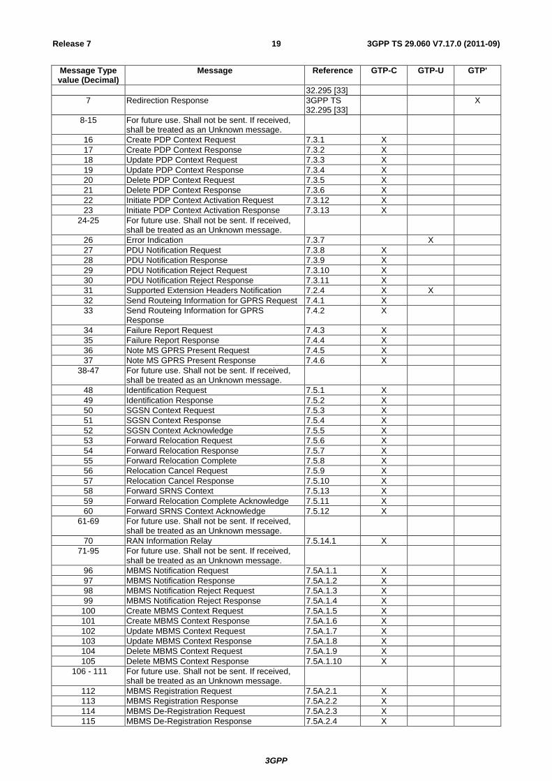
7 GTP Messages and Message Formats
7.1 Message Formats
GTP defines a set of messages between two associated GSNs or an SGSN and an RNC. The messages to be used are
defined in the table below. The three columns to the right define which parts (GTP-C, GTP-U or GTP') that send or
receive the specific message type.
Table 1: Messages in GTP
Message Type value (Decimal)
Message Reference GTP-C GTP-U GTP'
0 For future use. Shall not be sent. If received, shall be treated as an Unknown message.
1 Echo Request 7.2.1 X X x
2 Echo Response 7.2.2 X X x
3 Version Not Supported 7.2.3 X x
4 Node Alive Request 3GPP TS 32.295 [33]
X
5 Node Alive Response 3GPP TS 32.295 [33]
X
6 Redirection Request 3GPP TS X
3GPP
3GPP TS 29.060 V7.17.0 (2011-09) 19 Release 7
Message Type value (Decimal)
Message Reference GTP-C GTP-U GTP'
32.295 [33]
7 Redirection Response 3GPP TS 32.295 [33]
X
8-15 For future use. Shall not be sent. If received, shall be treated as an Unknown message.
16 Create PDP Context Request 7.3.1 X
17 Create PDP Context Response 7.3.2 X
18 Update PDP Context Request 7.3.3 X
19 Update PDP Context Response 7.3.4 X
20 Delete PDP Context Request 7.3.5 X
21 Delete PDP Context Response 7.3.6 X
22 Initiate PDP Context Activation Request 7.3.12 X
23 Initiate PDP Context Activation Response 7.3.13 X
24-25 For future use. Shall not be sent. If received, shall be treated as an Unknown message.
26 Error Indication 7.3.7 X
27 PDU Notification Request 7.3.8 X
28 PDU Notification Response 7.3.9 X
29 PDU Notification Reject Request 7.3.10 X
30 PDU Notification Reject Response 7.3.11 X
31 Supported Extension Headers Notification 7.2.4 X X
32 Send Routeing Information for GPRS Request 7.4.1 X
33 Send Routeing Information for GPRS Response
7.4.2 X
34 Failure Report Request 7.4.3 X
35 Failure Report Response 7.4.4 X
36 Note MS GPRS Present Request 7.4.5 X
37 Note MS GPRS Present Response 7.4.6 X
38-47 For future use. Shall not be sent. If received, shall be treated as an Unknown message.
48 Identification Request 7.5.1 X
49 Identification Response 7.5.2 X
50 SGSN Context Request 7.5.3 X
51 SGSN Context Response 7.5.4 X
52 SGSN Context Acknowledge 7.5.5 X
53 Forward Relocation Request 7.5.6 X
54 Forward Relocation Response 7.5.7 X
55 Forward Relocation Complete 7.5.8 X
56 Relocation Cancel Request 7.5.9 X
57 Relocation Cancel Response 7.5.10 X
58 Forward SRNS Context 7.5.13 X
59 Forward Relocation Complete Acknowledge 7.5.11 X
60 Forward SRNS Context Acknowledge 7.5.12 X
61-69 For future use. Shall not be sent. If received, shall be treated as an Unknown message.
70 RAN Information Relay 7.5.14.1 X
71-95 For future use. Shall not be sent. If received, shall be treated as an Unknown message.
96 MBMS Notification Request 7.5A.1.1 X
97 MBMS Notification Response 7.5A.1.2 X
98 MBMS Notification Reject Request 7.5A.1.3 X
99 MBMS Notification Reject Response 7.5A.1.4 X
100 Create MBMS Context Request 7.5A.1.5 X
101 Create MBMS Context Response 7.5A.1.6 X
102 Update MBMS Context Request 7.5A.1.7 X
103 Update MBMS Context Response 7.5A.1.8 X
104 Delete MBMS Context Request 7.5A.1.9 X
105 Delete MBMS Context Response 7.5A.1.10 X
106 - 111 For future use. Shall not be sent. If received, shall be treated as an Unknown message.
112 MBMS Registration Request 7.5A.2.1 X
113 MBMS Registration Response 7.5A.2.2 X
114 MBMS De-Registration Request 7.5A.2.3 X
115 MBMS De-Registration Response 7.5A.2.4 X

3GPP
3GPP TS 29.060 V7.17.0 (2011-09) 20 Release 7
Message Type value (Decimal)
Message Reference GTP-C GTP-U GTP'
116 MBMS Session Start Request 7.5A.2.5 X
117 MBMS Session Start Response 7.5A.2.6 X
118 MBMS Session Stop Request 7.5A.2.7 X
119 MBMS Session Stop Response 7.5A.2.8 X
120 MBMS Session Update Request 7.5A.2.9 X
121 MBMS Session Update Response 7.5A.2.10 X
122-127 For future use. Shall not be sent. If received, shall be treated as an Unknown message.
128 MS Info Change Notification Request 7.5B.1.1 X
129 MS Info Change Notification Response 7.5B.1.2 X
130-239 For future use. Shall not be sent. If received, shall be treated as an Unknown message.
240 Data Record Transfer Request 3GPP TS 32.295 [33]
X
241 Data Record Transfer Response 3GPP TS 32.295 [33]
X
242-254 For future use. Shall not be sent. If received, shall be treated as an Unknown message.
255 G-PDU 9.3.1 X
7.1.1 Presence requirements of Information Elements
There are three different presence requirements (Mandatory, Conditional, or Optional) for an IE within a given GTP-
PDU:
- Mandatory means that the IE shall be included by the sending side, and that the receiver diagnoses a
"Mandatory IE missing" error when detecting that the IE is not present.
- Conditional means:
that inclusion of the IE by the sender depends on conditions specified in the relevant protocol specification;
that the receiver can expect that the IE is present based on its parameter combination in the message and/or
on the state of the receiving node.
- Optional means that the IE shall be included as a service option. Therefore, the IE may be included or not in a
message.
For error handling, refer to section 11.
7.2 Path Management Messages
The Path Management messages may be sent between any type of GSN or GSN - RNC pair.
7.2.1 Echo Request
A GSN or an RNC may send an Echo Request on a path to the other GSN or RNC to find out if the peer GSN or RNC
is alive (see section Path Failure). Echo Request messages may be sent for each path in use. A path is considered to be
in use if at least one PDP context, or MBMS UE context, or MBMS bearer context uses the path to the other GSN or
RNC. When and how often an Echo Request message may be sent is implementation specific but an Echo Request shall
not be sent more often than every 60 s on each path.
A GSN or RNC shall be prepared to receive an Echo Request at any time and it shall reply with an Echo Response. The
optional Private Extension contains vendor or operator specific information.
Table 2: Information Elements in an Echo Request
Information element Presence requirement Reference
Private Extension Optional 7.7.46
3GPP
3GPP TS 29.060 V7.17.0 (2011-09) 21 Release 7
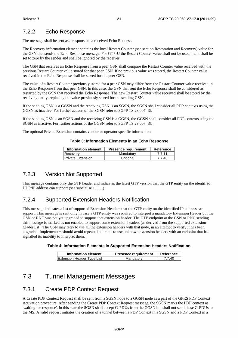
7.2.2 Echo Response
The message shall be sent as a response to a received Echo Request.
The Recovery information element contains the local Restart Counter (see section Restoration and Recovery) value for
the GSN that sends the Echo Response message. For GTP-U the Restart Counter value shall not be used, i.e. it shall be
set to zero by the sender and shall be ignored by the receiver.
The GSN that receives an Echo Response from a peer GSN shall compare the Restart Counter value received with the
previous Restart Counter value stored for that peer GSN. If no previous value was stored, the Restart Counter value
received in the Echo Response shall be stored for the peer GSN.
The value of a Restart Counter previously stored for a peer GSN may differ from the Restart Counter value received in
the Echo Response from that peer GSN. In this case, the GSN that sent the Echo Response shall be considered as
restarted by the GSN that received the Echo Response. The new Restart Counter value received shall be stored by the
receiving entity, replacing the value previously stored for the sending GSN.
If the sending GSN is a GGSN and the receiving GSN is an SGSN, the SGSN shall consider all PDP contexts using the
GGSN as inactive. For further actions of the SGSN refer to 3GPP TS 23.007 [3].
If the sending GSN is an SGSN and the receiving GSN is a GGSN, the GGSN shall consider all PDP contexts using the
SGSN as inactive. For further actions of the GGSN refer to 3GPP TS 23.007 [3].
The optional Private Extension contains vendor or operator specific information.
Table 3: Information Elements in an Echo Response
Information element Presence requirement Reference
Recovery Mandatory 7.7.11
Private Extension Optional 7.7.46
7.2.3 Version Not Supported
This message contains only the GTP header and indicates the latest GTP version that the GTP entity on the identified
UDP/IP address can support (see subclause 11.1.1).
7.2.4 Supported Extension Headers Notification
This message indicates a list of supported Extension Headers that the GTP entity on the identified IP address can
support. This message is sent only in case a GTP entity was required to interpret a mandatory Extension Header but the
GSN or RNC was not yet upgraded to support that extension header. The GTP endpoint at the GSN or RNC sending
this message is marked as not enabled to support some extension headers (as derived from the supported extension
header list). The GSN may retry to use all the extension headers with that node, in an attempt to verify it has been
upgraded. Implementers should avoid repeated attempts to use unknown extension headers with an endpoint that has
signalled its inability to interpret them.
Table 4: Information Elements in Supported Extension Headers Notification
Information element Presence requirement Reference
Extension Header Type List Mandatory 7.7.40
7.3 Tunnel Management Messages
7.3.1 Create PDP Context Request
A Create PDP Context Request shall be sent from a SGSN node to a GGSN node as a part of the GPRS PDP Context
Activation procedure. After sending the Create PDP Context Request message, the SGSN marks the PDP context as
'waiting for response'. In this state the SGSN shall accept G-PDUs from the GGSN but shall not send these G-PDUs to
the MS. A valid request initiates the creation of a tunnel between a PDP Context in a SGSN and a PDP Context in a
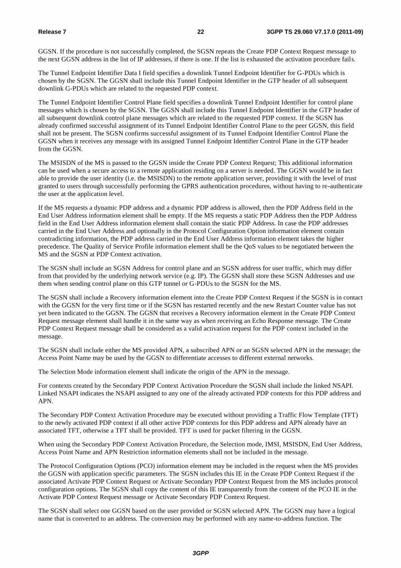
3GPP
3GPP TS 29.060 V7.17.0 (2011-09) 22 Release 7
GGSN. If the procedure is not successfully completed, the SGSN repeats the Create PDP Context Request message to
the next GGSN address in the list of IP addresses, if there is one. If the list is exhausted the activation procedure fails.
The Tunnel Endpoint Identifier Data I field specifies a downlink Tunnel Endpoint Identifier for G-PDUs which is
chosen by the SGSN. The GGSN shall include this Tunnel Endpoint Identifier in the GTP header of all subsequent
downlink G-PDUs which are related to the requested PDP context.
The Tunnel Endpoint Identifier Control Plane field specifies a downlink Tunnel Endpoint Identifier for control plane
messages which is chosen by the SGSN. The GGSN shall include this Tunnel Endpoint Identifier in the GTP header of
all subsequent downlink control plane messages which are related to the requested PDP context. If the SGSN has
already confirmed successful assignment of its Tunnel Endpoint Identifier Control Plane to the peer GGSN, this field
shall not be present. The SGSN confirms successful assignment of its Tunnel Endpoint Identifier Control Plane the
GGSN when it receives any message with its assigned Tunnel Endpoint Identifier Control Plane in the GTP header
from the GGSN.
The MSISDN of the MS is passed to the GGSN inside the Create PDP Context Request; This additional information
can be used when a secure access to a remote application residing on a server is needed. The GGSN would be in fact
able to provide the user identity (i.e. the MSISDN) to the remote application server, providing it with the level of trust
granted to users through successfully performing the GPRS authentication procedures, without having to re-authenticate
the user at the application level.
If the MS requests a dynamic PDP address and a dynamic PDP address is allowed, then the PDP Address field in the
End User Address information element shall be empty. If the MS requests a static PDP Address then the PDP Address
field in the End User Address information element shall contain the static PDP Address. In case the PDP addresses
carried in the End User Address and optionally in the Protocol Configuration Option information element contain
contradicting information, the PDP address carried in the End User Address information element takes the higher
precedence. The Quality of Service Profile information element shall be the QoS values to be negotiated between the
MS and the SGSN at PDP Context activation.
The SGSN shall include an SGSN Address for control plane and an SGSN address for user traffic, which may differ
from that provided by the underlying network service (e.g. IP). The GGSN shall store these SGSN Addresses and use
them when sending control plane on this GTP tunnel or G-PDUs to the SGSN for the MS.
The SGSN shall include a Recovery information element into the Create PDP Context Request if the SGSN is in contact
with the GGSN for the very first time or if the SGSN has restarted recently and the new Restart Counter value has not
yet been indicated to the GGSN. The GGSN that receives a Recovery information element in the Create PDP Context
Request message element shall handle it in the same way as when receiving an Echo Response message. The Create
PDP Context Request message shall be considered as a valid activation request for the PDP context included in the
message.
The SGSN shall include either the MS provided APN, a subscribed APN or an SGSN selected APN in the message; the
Access Point Name may be used by the GGSN to differentiate accesses to different external networks.
The Selection Mode information element shall indicate the origin of the APN in the message.
For contexts created by the Secondary PDP Context Activation Procedure the SGSN shall include the linked NSAPI.
Linked NSAPI indicates the NSAPI assigned to any one of the already activated PDP contexts for this PDP address and
APN.
The Secondary PDP Context Activation Procedure may be executed without providing a Traffic Flow Template (TFT)
to the newly activated PDP context if all other active PDP contexts for this PDP address and APN already have an
associated TFT, otherwise a TFT shall be provided. TFT is used for packet filtering in the GGSN.
When using the Secondary PDP Context Activation Procedure, the Selection mode, IMSI, MSISDN, End User Address,
Access Point Name and APN Restriction information elements shall not be included in the message.
The Protocol Configuration Options (PCO) information element may be included in the request when the MS provides
the GGSN with application specific parameters. The SGSN includes this IE in the Create PDP Context Request if the
associated Activate PDP Context Request or Activate Secondary PDP Context Request from the MS includes protocol
configuration options. The SGSN shall copy the content of this IE transparently from the content of the PCO IE in the
Activate PDP Context Request message or Activate Secondary PDP Context Request.
The SGSN shall select one GGSN based on the user provided or SGSN selected APN. The GGSN may have a logical
name that is converted to an address. The conversion may be performed with any name-to-address function. The

3GPP
3GPP TS 29.060 V7.17.0 (2011-09) 23 Release 7
converted address shall be stored in the "GGSN Address in Use" field in the PDP context and be used during the entire
lifetime of the PDP context.
If the converted address includeds an IPv6 address, the IPv4/IPv6 capable SGSN sends Create PDP Context Request to
the GGSN including IPv6 addresses in the fields SGSN Address for Control Plane and SGSN Address for user traffic.If
the converted address only includes an IPv4 address, IPv4/IPv6 capable SGSN shall include IPv4 addresses in the fields
SGSN Address for Control Plane and SGSN Address for user traffic.
NOTE: A DNS query may be used as the name-to-IP address mapping of the GGSN. The IP address returned in
the DNS response is then stored in the "GGSN Address in Use" field in the PDP context.
The IMSI information element together with the NSAPI information element uniquely identifies the PDP context to be
created.
The SGSN shall not send a Create PDP Context Request for an already active context.
If a new Create PDP Context Request is incoming on TEID 0 for an already active PDP context, this Create PDP
Context Request must be considered related to a new session. The existing PDP context shall be torn down locally, and
the associated PDP contexts deleted locally, before the new session is created. If a new Create PDP Context Request is
incoming on a TEID which is different from 0 and this TEID is already allocated to one or more activated PDP
contexts, and the NSAPI IE value in this message matches the NSAPI value of an active PDP context, the GGSN shall
send back a Create PDP Context Response with a rejection cause code. It is implementation dependent deciding
whether to teardown or keep the existing PDP context.
If the GGSN uses the MNRG flag and the flag is set, the GGSN should treat the Create PDP Context Request as a Note
MS Present Request and clear the MNRG flag.
The SGSN shall determine Charging Characteristics from the Subscribed Charging Characteristics and/or PDP Context
Charging Characteristics depending on the presence of the information in the Packet Domain Subscription Data as
defined in 3GPP TS 23.060 [4]. The requirements for the presence of the Charging Characteristics IE are defined in
3GPP TS 23.060 [4]. The contents of the Charging Characteristics IE are defined in 3GPP TS 32.251 [18] and
3GPP TS 32.298 [34].
The SGSN shall include Trace Reference, Trace Type, Trigger Id, OMC Identity and Additional Trace Info (Trace
reference2, Trace Recording Session Reference, triggering events in GGSN, Trace Depth, List of interfaces to trace in
GGSN and Trace Activity Control) in the message if GGSN trace is activated. The SGSN shall copy Trace Reference,
Trace Type, OMC Identity and Additional Trace Info from the trace request received from the HLR or OMC and the
Trace Activity Control shall be set to Trace Activation
For more detailed description of Trace Session activation/deactivation procedures see 3GPP TS 32.422 [31]
For SGSN and GGSN trace record description see 3GPP TS 32.423 [32].
The SGSN may include the Routeing Area Identity (RAI) of the SGSN where the MS is registered. The MCC and MNC
components shall be populated with the MCC and MNC, respectively, of the SGSN where the MS is registered. The
LAC and RAC components shall be populated by the SGSN with the value of 'FFFE' and 'FF', respectively.
The APN Restriction is an optional information element. In this instance it is used by the SGSN to convey to the GGSN
the highest restriction type out of all the currently active PDP Contexts for a particular subscriber.
The presence of the Common Flags IE is optional. If the NRSN bit of the Common Flags IE is set to 1, the SGSN
supports the network requested bearer control. If NRSN bit of the Common Flags IE is set to 0 or the Common Flags IE
is absent then the SGSN does not support network requested bearer control.If the Upgrade QoS Supported bit of the
Common Flags IE is set to 1, the SGSN supports the QoS upgrade in Response message functionality. If Upgrade QoS
Supported bit of the Common Flags IE is set to 0 or the Common Flags IE is absent then the SGSN does not support
QoS upgrade in Response message functionality.
The SGSN may include the User Location Information IE, MS Time Zone IE, RAT Type IE, IMEI(SV) IE and the
CAMEL Charging Information Container IE if they are available (see sub-clause 15.1.1a of 3GPP TS 23.060 [4] for
more information). If the User Location Information IE is included then the SGSN shall include the CGI or SAI in the
'Geographic Location' field depending on whether the MS is in a cell or a service area respectively.
The Correlation-ID shall be included if the PDP Context Activation is performed as part of the Network Requested
Secondary PDP Context Activation Procedure.
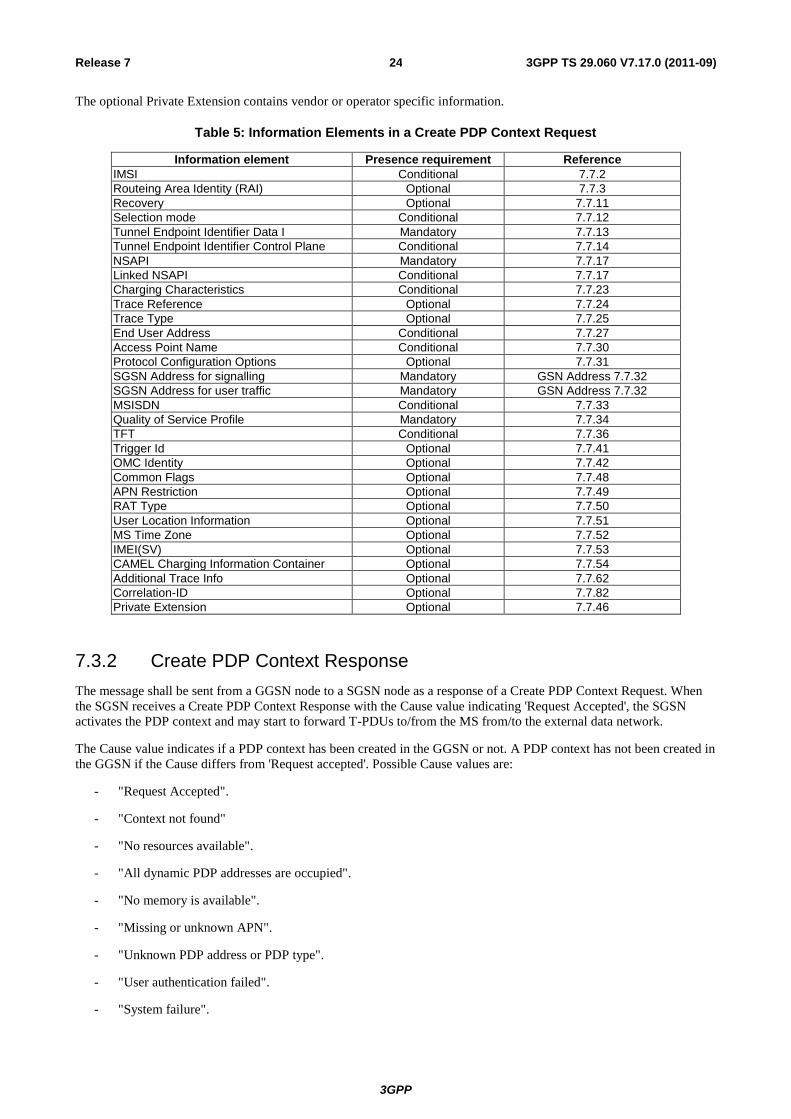
3GPP
3GPP TS 29.060 V7.17.0 (2011-09) 24 Release 7
The optional Private Extension contains vendor or operator specific information.
Table 5: Information Elements in a Create PDP Context Request
Information element Presence requirement Reference
IMSI Conditional 7.7.2
Routeing Area Identity (RAI) Optional 7.7.3
Recovery Optional 7.7.11
Selection mode Conditional 7.7.12
Tunnel Endpoint Identifier Data I Mandatory 7.7.13
Tunnel Endpoint Identifier Control Plane Conditional 7.7.14
NSAPI Mandatory 7.7.17
Linked NSAPI Conditional 7.7.17
Charging Characteristics Conditional 7.7.23
Trace Reference Optional 7.7.24
Trace Type Optional 7.7.25
End User Address Conditional 7.7.27
Access Point Name Conditional 7.7.30
Protocol Configuration Options Optional 7.7.31
SGSN Address for signalling Mandatory GSN Address 7.7.32
SGSN Address for user traffic Mandatory GSN Address 7.7.32
MSISDN Conditional 7.7.33
Quality of Service Profile Mandatory 7.7.34
TFT Conditional 7.7.36
Trigger Id Optional 7.7.41
OMC Identity Optional 7.7.42
Common Flags Optional 7.7.48
APN Restriction Optional 7.7.49
RAT Type Optional 7.7.50
User Location Information Optional 7.7.51
MS Time Zone Optional 7.7.52
IMEI(SV) Optional 7.7.53
CAMEL Charging Information Container Optional 7.7.54
Additional Trace Info Optional 7.7.62
Correlation-ID Optional 7.7.82
Private Extension Optional 7.7.46
7.3.2 Create PDP Context Response
The message shall be sent from a GGSN node to a SGSN node as a response of a Create PDP Context Request. When
the SGSN receives a Create PDP Context Response with the Cause value indicating 'Request Accepted', the SGSN
activates the PDP context and may start to forward T-PDUs to/from the MS from/to the external data network.
The Cause value indicates if a PDP context has been created in the GGSN or not. A PDP context has not been created in
the GGSN if the Cause differs from 'Request accepted'. Possible Cause values are:
- "Request Accepted".
- "Context not found"
- "No resources available".
- "All dynamic PDP addresses are occupied".
- "No memory is available".
- "Missing or unknown APN".
- "Unknown PDP address or PDP type".
- "User authentication failed".
- "System failure".

3GPP
3GPP TS 29.060 V7.17.0 (2011-09) 25 Release 7
- "Semantic error in the TFT operation".
- "Syntactic error in the TFT operation".
- "Semantic errors in packet filter(s)".
- "Syntactic errors in packet filters(s)".
- "Mandatory IE incorrect".
- "Mandatory IE missing".
- "Optional IE incorrect".
- "Invalid message format".
- "PDP context without TFT already activated".
- "APN access denied – no subscription".
- "APN Restriction type incompatibility with currently active PDP Contexts"
'No resources available' indicates that not enough resources are available within the network to allow the PDP Context
to be created. 'Missing or unknown APN' indicates e.g. when the GGSN does not support the Access Point Name.
'Unknown PDP address or PDP type' indicates when the GGSN does not support the PDP type or the PDP address.
'User authentication failed' indicates that the external packet network has rejected the service requested by the user e.g.
the authentication check in the RADIUS server failed. 'PDP context without TFT already activated' indicates that a PDP
context has already been activated without a TFT for that MS. 'Context not found' indicates that a Create PDP Request
for a subsequent PDP context has been received, but the PDP context associated with the request, which the SGSN
believes to be active does not exist on the GGSN. 'APN access denied – no subscription' indicates that the GGSN has
denied the user access to an APN because a subscription is required, but the subscriber does not have the necessary
subscription.
Only the Cause information element, optionally Protocol Configuration Options and optionally the Recovery
information element shall be included in the response if the Cause contains another value than 'Request accepted'.
All information elements, except Recovery, Protocol Configuration Options, Charging Gateway Address, Tunnel
Endpoint Identifier Control Plane and Private Extension, are mandatory if the Cause contains the value 'Request
accepted'.
The Tunnel Endpoint Identifier for Data (I) field specifies an uplink Tunnel Endpoint Identifier for G-PDUs that is
chosen by the GGSN. The SGSN shall include this Tunnel Endpoint Identifier in the GTP header of all subsequent
uplink G-PDUs which are related to the requested PDP context.
The Tunnel Endpoint Identifier Control Plane field specifies an uplink Tunnel Endpoint Identifier for control plane
messages, which is chosen by the GGSN. The SGSN shall include this Tunnel Endpoint Identifier in the GTP header of
all subsequent uplink-control plane messages, which are related to the requested PDP context. If the GGSN has already
confirmed successful assignment of its Tunnel Endpoint Identifier Control Plane to the peer SGSN, this field shall not
be present. The GGSN confirms successful assignment of its Tunnel Endpoint Identifier Control Plane to the SGSN
when it receives any message with its assigned Tunnel Endpoint Identifier Control Plane in the GTP header from the
SGSN.
The GGSN may include the NSAPI received from the SGSN in the Create PDP Context Request message, in order to
facilitate error handling in SGSN.
NOTE: If an SGSN receives a Create PDP Context Response with an NSAPI IE included for which there is no
corresponding outstanding request, an SGSN may send a Delete PDP Context Request towards the GGSN
that sent the Create PDP Context Response with the NSAPI included
The GGSN shall include a GGSN Address for control plane and a GGSN address for user traffic, which may differ from
that provided by the underlying network service (e.g. IP).
If the Create PDP Context Request received from the SGSN included IPv6 SGSN address, an IPv4/IPv6 capable GGSN
shall include IPv6 addresses in the fields GGSN Address for Control Plane and GGSN Address for user traffic, and
IPv4 addresses in the fields Alternative GGSN Address for Control Plane and Alternative GGSN Address for user

3GPP
3GPP TS 29.060 V7.17.0 (2011-09) 26 Release 7
traffic. If SGSN included IPv4 SGSN addresses in the request, an IPv4/IPv6 capable GGSN shall include IPv4
addresses in the fields GGSN Address for Control Plane and GGSN Address for user traffic, and IPv6 addresses in the
fields Alternative GGSN Address for Control Plane and Alternative GGSN Address for user traffic. An IPv4/IPv6
capable SGSN shall store these GGSN Addresses and use one set of them when sending control plane on this GTP
tunnel or G-PDUs to the GGSN for the MS. An IPv4 only SGSN shall not store the IPv6 address included in the
Alternative GGSN Address.
If the MS requests a dynamic PDP address with the PDP Type IPv4 or IPv6 and a dynamic PDP address is allowed,
then the End User Address information element shall be included and the PDP Address field in the End User Address
information element shall contain the dynamic PDP Address allocated by the GGSN.
If the MS requests a static PDP address with the PDP Type IPv4 or IPv6, or a PDP address is specified with PDP Type
PPP, then the End User Address information element shall be included and the PDP Address field shall not be included.
The PDP address in End User Address IE and in the Protocol configuration options IE shall be the same, if both IEs are
present in the create PDP context response. When using the Secondary PDP Context Activation Procedure, the End
User Address element shall not be included in the message.
The QoS values supplied in the Create PDP Context Request may be negotiated downwards by the GGSN. If the SGSN
has indicated support for upgrade of QoS in the request message, the QoS values may also be negotiated upwards by the
GGSN.The negotiated values or the original values from SGSN are inserted in the Quality of Service Profile
information element of the Create PDP Context Response message.
The GGSN may start to forward T-PDUs after the Create PDP Context Response has been sent. The SGSN may start to
forward T-PDUs when the Create PDP Context Response has been received. In this case the SGSN shall also be
prepared to receive T-PDUs from the GGSN after it has sent a Create PDP Context Request but before a Create PDP
Context Response has been received.
The Reordering Required value supplied in the Create PDP Context Response indicates whether the end user protocol
benefits from packet in sequence delivery and whether the SGSN and the GGSN therefore shall perform reordering or
not. In other words, if reordering is required by the GGSN, the SGSN and the GGSN shall perform reordering of
incoming T-PDUs on this path. When the Quality of Service (QoS) Profile is Release 99 the receiving entity shall
ignore the Reordering Required.
The GGSN shall include the Recovery information element into the Create PDP Context Response if the GGSN is in
contact with the SGSN for the first time or the GGSN has restarted recently and the new Restart Counter value has not
yet been indicated to the SGSN. The SGSN receiving the Recovery information element shall handle it as when an
Echo Response message is received but shall consider the PDP context being created as active if the response indicates
successful context activation at the GGSN.
The Charging ID is used to identify all charging records produced in SGSN(s) and the GGSN for this PDP context. The
Charging ID is generated by the GGSN and shall be unique within the GGSN.
The Charging Gateway Address is the IP address of the recommended Charging Gateway Functionality to which the
SGSN should transfer the Charging Detail Records (CDR) for this PDP Context.
The Alternative Charging Gateway Address IE has a similar purpose as the Charging Gateway Address but enables co-
existence of IPv4 and IPv6 stacks in the Ga charging interfaces, without mandating any node to have a dual stack. The
format of the optional Alternative Charging Gateway Address information element is the same as the format of the
Charging Gateway Address.
When both these addresses are present, the Charging Gateway address IE shall contain the IPv4 address of the Charging
Gateway Function and the Alternative Charging Gateway address IE shall contain the IPv6 address of the Charging
Gateway Function.
NOTE: The Charging Gateway Address and Alternative Charging Gateway Address both refer to the same
Charging Gateway Function.
The APN Restriction is an optional information element. In this instance it is used by the GGSN to convey to the SGSN
the restriction type of the associated PDP Context being set up.
The optional Private Extension contains vendor or operator specific information.
The Protocol Configuration Options (PCO) information element may be included in the response when the GGSN
provides the MS with application specific parameters or to indicate the Bearer Control Mode to the MS.

3GPP
3GPP TS 29.060 V7.17.0 (2011-09) 27 Release 7
If Bearer Control Mode is provided by the GGSN in the PCO, the Bearer Control Mode IE shall be included in order to
inform the SGSN about the bearer control mode and shall indicate the same bearer control mode as indicated to the MS
in the PCO.
The presence of the Common Flags IE is optional. If the Prohibit Payload Compression bit of the Common Flags IE is
set to 1, then for A/Gb mode access the SGSN shall not compress the payload of user data regardless of whether the
user asks for payload compression. If the Prohibit Payload Compression bit of the Common Flags IE is set to 0 or the
Common Flags IE is absent then the SGSN shall perform payload compression when the user asks for it as per normal
operation.
If the MS Info Change Reporting mechanism is to be started or stopped for this subscriber, then the GGSN shall include
the MS Info Change Reporting Action IE in the message and shall set the value of the Action field appropriately.
Table 6: Information Elements in a Create PDP Context Response
Information element Presence requirement Reference
Cause Mandatory 7.7.1
Reordering required Conditional 7.7.6
Recovery Optional 7.7.11
Tunnel Endpoint Identifier Data I Conditional 7.7.13
Tunnel Endpoint Identifier Control Plane Conditional 7.7.14
NSAPI Optional 7.7.17
Charging ID Conditional 7.7.26
End User Address Conditional 7.7.27
Protocol Configuration Options Optional 7.7.31
GGSN Address for Control Plane Conditional GSN Address 7.7.32
GGSN Address for user traffic Conditional GSN Address 7.7.32
Alternative GGSN Address for Control Plane Conditional GSN Address 7.7.32
Alternative GGSN Address for user traffic Conditional GSN Address 7.7.32
Quality of Service Profile Conditional 7.7.34
Charging Gateway Address Optional 7.7.44
Alternative Charging Gateway Address Optional 7.7.44
Common Flags Optional 7.7.48
APN Restriction Optional 7.7.49
MS Info Change Reporting Action Optional 7.7.80
Bearer Control Mode Optional 7.7.83
Private Extension Optional 7.7.46
7.3.3 Update PDP Context Request
An Update PDP Context Request message shall be sent from an SGSN to a GGSN as part of the GPRS inter-SGSN
Routeing Area Update procedure, the PDP Context Modification procedure, to redistribute contexts due to load sharing
or as part of the inter-system intra-SGSN update procedure i.e. UE transitioning between UTRAN and GERAN A/Gb
mode (and vice versa) on the same SGSN and if the SGSN decides to enable a direct GTP-U tunnel between the GGSN
and the RNC. It shall be used to change the QoS and the path. In addition it shall be used if it is necessary to change the
GTP version of a tunnel to a GGSN from GTP v0 to GTP v1. For the inter-SGSN Routeing Area Update procedure the
message shall be sent by the new SGSN. The Update PDP Context Request shall also be used as part of the Secondary
PDP Context Activation Procedure to indicate that RAN Procedures are ready and that the SGSN is ready to receive
payload from the GGSN on the new PDP Context.
The NSAPI information element together with the Tunnel Endpoint Identifier in the GTP header unambiguously
identifies a PDP Context in the GGSN.
The IMSI shall be included if the message is sent during an Inter SGSN change when changing the GTP version from
GTP v0 to GTP v1; this is required, as the TEID in the header of the message is set to all zeros in this case.
The Tunnel Endpoint Identifier Data field specifies a downlink Tunnel Endpoint Identifier for G-PDUs which is chosen
by the SGSN. The GGSN shall include this Tunnel Endpoint Identifier in the GTP header of all subsequent downlink
G-PDUs that are related to the requested PDP context.

3GPP
3GPP TS 29.060 V7.17.0 (2011-09) 28 Release 7
The Tunnel Endpoint Identifier Control Plane field specifies a downlink Tunnel Endpoint Identifier Control Plane
messages which is chosen by the SGSN. The GGSN shall include this Tunnel Endpoint Identifier in the GTP header of
all subsequent downlink control plane messages that are related to the requested PDP context. If the SGSN has already
confirmed successful assignment of its Tunnel Endpoint Identifier Control Plane to the peer GGSN, this field shall not
be present. The SGSN confirms successful assignment of its Tunnel Endpoint Identifier Control Plane to the GGSN
when it receives any message with its assigned Tunnel Endpoint Identifier Control Plane in the GTP header from the
GGSN.
The Quality of Service Profile information element shall include the QoS negotiated between the MS and SGSN at PDP
Context activation or the new QoS negotiated in the PDP Context Modification procedure.
The SGSN shall include an SGSN Address for control plane and an SGSN address for user traffic, which may differ
from that provided by the underlying network service (e.g. IP).
If an IPv4/IPv6 capable SGSN received IPv4 GGSN addresses from the old SGSN, it shall include IPv4 addresses in
the fields SGSN Address for Control Plane and SGSN Address for User Traffic and IPv6 addresses in the fields
Alternative SGSN Address for Control Plane and Alternative SGSN Address for User Traffic. Otherwise, an IPv4/IPv6
capable SGSN shall use only SGSN IPv6 addresses if it has GGSN IPv6 addresses available. If the GGSN supports
IPv6 below GTP, it shall store and use the IPv6 SGSN addresses for communication with the SGSN and ignore the IPv4
SGSN addresses. If the GGSN supports only IPv4 below GTP, it shall store and use the IPv4 SGSN addresses for
communication with the SGSN and ignore the IPv6 SGSN addresses. When active contexts are being redistributed due
to load sharing, G-PDUs that are in transit across the Gn-interface are in an undetermined state and may be lost.
The SGSN shall include a Recovery information element into the Update PDP Context Request if the SGSN is in
contact with the GGSN for the very first time or if the SGSN has restarted recently and the new Restart Counter value
has not yet been indicated to the GGSN. The GGSN that receives a Recovery information element in the Update PDP
Context Request message element shall handle it in the same way as when receiving an Echo Response message. The
Update PDP Context Request message shall be considered as a valid update request for the PDP context indicated in the
message.
The Traffic Flow Template (TFT) is used to distinguish between different user traffic flows.
The SGSN shall include Trace Reference, Trace Type, Trigger Id, OMC Identity and Additional Trace Info (Trace
reference 2, Trace Recording Session Reference, triggering events in GGSN, Trace Depth, List of interfaces to trace in
GGSN and Trace Activity Control) in the message if GGSN trace is activated while the PDP context is active. The
SGSN shall copy Trace Reference, Trace Type, OMC Identity and Additional Trace Info from the trace request
received from the HLR or OMC and the Trace Activity Control of the Additional Trace Info shall be set to Trace
Activation
If SGSN deactivates the Trace Session to GGSN, the SGSN shall include the Additional Trace Info in the message and
the Trace Activity Control shall be set to Trace Deactivation.
For more detailed description of Trace Session activation/deactivation procedures see 3GPP TS 32.422 [31]
For SGSN and GGSN trace record description see 3GPP TS 32.423 [32]
The SGSN may include the Routeing Area Identity (RAI) of the SGSN where the MS is registered. The MCC and MNC
components shall be populated with the MCC and MNC, respectively, of the SGSN where the MS is registered. The
LAC and RAC components shall be populated by the SGSN with the value of 'FFFE' and 'FF', respectively.
The optional Private Extension contains vendor or operator specific information.
The MS includes the Protocol Configuration Options (PCO) information element in the request if the MS wishes to
provide the GGSN with application specific parameters. The SGSN includes this IE in the Update PDP Context Request
if the associated Modify PDP Context Request from the MS includes protocol configuration options. The SGSN shall
copy the content of this IE transparently from the content of the PCO IE in the Modify PDP Context Request message.
The presence of the Common Flags IE is optional. If the RAN Procedures Ready bit of the Common Flags IE is set to 1,
then SGSN is ready to receive payload on the PDP Context indicated in the message. If RAN Procedures Ready bit of
the Common Flags IE is set to 0 or the Common Flags IE is absent then the RAN procedures in the SGSN may or may
not be ready. If the NRSN bit of the Common Flags IE is set to 1, the SGSN supports the network requested bearer
control. If NRSN bit of the Common Flags IE is set to 0 or the Common Flags IE is absent then the SGSN does not
support network requested bearer control. Handling of the Common Flags IE (also the handling of "No QoS
negotiation" bit in the Common Flags IE) by GGSN is specified in subclause 7.3.4 "Update PDP Context Response". If

3GPP
3GPP TS 29.060 V7.17.0 (2011-09) 29 Release 7
the "No QoS negotiation" bit of the Common Flags IE is set to 0 or the Common Flags IE is absent then the GGSN may
re-negotiate QoS in the corresponding Update PDP Context Response. If the Upgrade QoS Supported bit of the
Common Flags IE is set to 1, the SGSN supports the QoS upgrade in Response message functionality. If Upgrade QoS
Supported bit of the Common Flags IE is set to 0 or the Common Flags IE is absent then the SGSN does not support
QoS upgrade in Response message functionality.
If the Direct Tunnel Flags IE is included and if the DTI bit of the Direct Tunnel Flags IE is set to 1, this indicates to the
GGSN that for this PDP Context the SGSN is invoking a direct tunnel. If the DTI bit of the Direct Tunnel Flags IE is set
to 0 or the Direct Tunnel Flags IE is absent, this indicates to the GGSN that for this PDP Context the SGSN is not
invoking a direct tunnel. All other fields of the Direct Tunnel Flags IE shall be ignored.
The SGSN may include the User Location Information IE, RAT Type IE and MS Time Zone IE if they are available
(see sub-clause 15.1.1a of 3GPP TS 23.060 [4] for more information). If the User Location Information IE is included
then the SGSN shall include the CGI or SAI in the 'Geographic Location' field depending on whether the MS is in a cell
or a service area respectively.
Table 7: Information Elements in an SGSN-Initiated Update PDP Context Request
Information element Presence requirement Reference
IMSI Conditional 7.7.2
Routeing Area Identity (RAI) Optional 7.7.3
Recovery Optional 7.7.11
Tunnel Endpoint Identifier Data I Mandatory 7.7.13
Tunnel Endpoint Identifier Control Plane Conditional 7.7.14
NSAPI Mandatory 7.7.17
Trace Reference Optional 7.7.24
Trace Type Optional 7.7.25
Protocol Configuration Options Optional 7.7.31
SGSN Address for Control Plane Mandatory GSN Address 7.7.32
SGSN Address for User Traffic Mandatory GSN Address 7.7.32
Alternative SGSN Address for Control Plane Conditional GSN Address 7.7.32
Alternative SGSN Address for User Traffic Conditional GSN Address 7.7.32
Quality of Service Profile Mandatory 7.7.34
TFT Optional 7.7.36
Trigger Id Optional 7.7.41
OMC Identity Optional 7.7.42
Common Flags Optional 7.7.48
RAT Type Optional 7.7.50
User Location Information Optional 7.7.51
MS Time Zone Optional 7.7.52
Additonal Trace Info Optional 7.7.62
Direct Tunnel Flags Optional 7.7.81
Private Extension Optional 7.7.46
An Update PDP Context Request may also be sent from a GGSN to an SGSN to re-negotiate the QoS of a PDP context.
The GGSN-initiated Update PDP Context Request can also be used to provide a PDP address to the SGSN (and MS).
The latter shall be used by GGSN when it acts as a DHCP Relay Agent or Mobil IP Foreign Agent. A GGSN may send
an update PDP context to a SGSN to check that the PDP context is still active at the SGSN. In such a case, the GGSN
shall include the optional IMSI IE, to add robustness against the case the SGSN has re-assigned the TEID to another
PDP context (this may happen when the PDP context is dangling at the GGSN). Also, the "Quality of service profile"
IE and the "End user Address" IE shall not be included in this case. For network requested bearer control a GGSN may
send an update PDP context to a SGSN in order to add, modify or delete the TFT related to the PDP Context or to
change the Bearer Control Mode. A GGSN sends an Update PDP Context to an SGSN when a direct tunnel is used and
the GGSN receives an Error Indication message from the RNC. In such a case, the GGSN shall include the NSAPI IE
and the Direct Tunnel Flags IE with the EI bit set.
NOTE: SGSN and GGSN behaviour for RNC failure and recovery is defined in 3GPP TS 23.060 [4].
The Quality of Service Profile information element shall include the GGSN requested QoS.
The End User Address information element shall contain a valid IPv4 or IPv6 address.
The GGSN shall include a Recovery information element into the Update PDP Context Request if the GGSN has
restarted recently and the new Restart Counter value has not yet been indicated to the SGSN. The SGSN that receives a
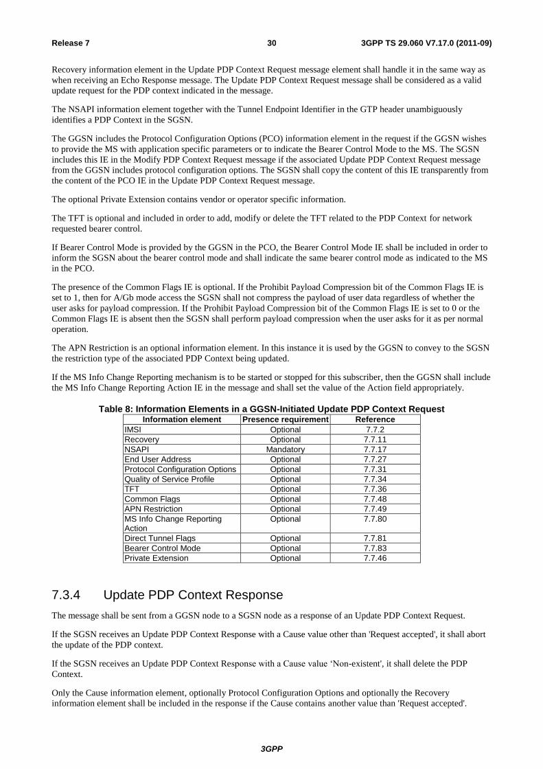
3GPP
3GPP TS 29.060 V7.17.0 (2011-09) 30 Release 7
Recovery information element in the Update PDP Context Request message element shall handle it in the same way as
when receiving an Echo Response message. The Update PDP Context Request message shall be considered as a valid
update request for the PDP context indicated in the message.
The NSAPI information element together with the Tunnel Endpoint Identifier in the GTP header unambiguously
identifies a PDP Context in the SGSN.
The GGSN includes the Protocol Configuration Options (PCO) information element in the request if the GGSN wishes
to provide the MS with application specific parameters or to indicate the Bearer Control Mode to the MS. The SGSN
includes this IE in the Modify PDP Context Request message if the associated Update PDP Context Request message
from the GGSN includes protocol configuration options. The SGSN shall copy the content of this IE transparently from
the content of the PCO IE in the Update PDP Context Request message.
The optional Private Extension contains vendor or operator specific information.
The TFT is optional and included in order to add, modify or delete the TFT related to the PDP Context for network
requested bearer control.
If Bearer Control Mode is provided by the GGSN in the PCO, the Bearer Control Mode IE shall be included in order to
inform the SGSN about the bearer control mode and shall indicate the same bearer control mode as indicated to the MS
in the PCO.
The presence of the Common Flags IE is optional. If the Prohibit Payload Compression bit of the Common Flags IE is
set to 1, then for A/Gb mode access the SGSN shall not compress the payload of user data regardless of whether the
user asks for payload compression. If the Prohibit Payload Compression bit of the Common Flags IE is set to 0 or the
Common Flags IE is absent then the SGSN shall perform payload compression when the user asks for it as per normal
operation.
The APN Restriction is an optional information element. In this instance it is used by the GGSN to convey to the SGSN
the restriction type of the associated PDP Context being updated.
If the MS Info Change Reporting mechanism is to be started or stopped for this subscriber, then the GGSN shall include
the MS Info Change Reporting Action IE in the message and shall set the value of the Action field appropriately.
Table 8: Information Elements in a GGSN-Initiated Update PDP Context RequestInformation element Presence requirement Reference
IMSI Optional 7.7.2
Recovery Optional 7.7.11
NSAPI Mandatory 7.7.17
End User Address Optional 7.7.27
Protocol Configuration Options Optional 7.7.31
Quality of Service Profile Optional 7.7.34
TFT Optional 7.7.36
Common Flags Optional 7.7.48
APN Restriction Optional 7.7.49
MS Info Change Reporting Action
Optional 7.7.80
Direct Tunnel Flags Optional 7.7.81
Bearer Control Mode Optional 7.7.83
Private Extension Optional 7.7.46
7.3.4 Update PDP Context Response
The message shall be sent from a GGSN node to a SGSN node as a response of an Update PDP Context Request.
If the SGSN receives an Update PDP Context Response with a Cause value other than 'Request accepted', it shall abort
the update of the PDP context.
If the SGSN receives an Update PDP Context Response with a Cause value ‘Non-existent', it shall delete the PDP
Context.
Only the Cause information element, optionally Protocol Configuration Options and optionally the Recovery
information element shall be included in the response if the Cause contains another value than 'Request accepted'.
3GPP
3GPP TS 29.060 V7.17.0 (2011-09) 31 Release 7
Possible Cause values are:
- 'Request Accepted'.
- 'Non-existent'.
- 'Service not supported'.
- 'System failure'.
- 'Semantic error in the TFT operation'.
- 'Syntactic error in the TFT operation'.
- 'Semantic errors in packet filter(s)'.
- 'Syntactic errors in packet filters(s)'.
- 'Mandatory IE incorrect'.
- 'Mandatory IE missing'.
- 'Optional IE incorrect'.
- 'Invalid message format'.
The Tunnel Endpoint Identifier Data field specifies an uplink Tunnel Endpoint Identifier for G-PDUs that is chosen by
the GGSN. The SGSN shall include this Tunnel Endpoint Identifier in the GTP header of all subsequent uplink G-PDUs
that are related to the requested PDP context. This information element shall be included if the Cause contains the value
'Request accepted'.
The Tunnel Endpoint Identifier Control Plane field specifies an uplink Tunnel Endpoint Identifier Control Plane
messages which is chosen by the GGSN. The SGSN shall include this Tunnel Endpoint Identifier in the GTP header of
all subsequent uplink control plane messages which are related to the requested PDP context. If the GGSN has already
confirmed successful assignment of its Tunnel Endpoint Identifier Control Plane to the peer SGSN, this field shall not
be present. The GGSN confirms successful assignment of its Tunnel Endpoint Identifier Control Plane to the SGSN
when it receives any message with its assigned Tunnel Endpoint Identifier Control Plane in the GTP header from the
SGSN.
The QoS values supplied in the Update PDP Context Request may be negotiated downwards by the GGSN. If the
SGSN has indicated support for upgrade of QoS in the request message, the QoS values may also be negotiated
upwards by the GGSN. In case the "No QoS negotiation" flag has been set to 1 by the SGSN in the corresponding
request, the QoS values shall not be renegotiated, neither upwards, nor downwards (see also PCO handling below). The
negotiated values or the original value from SGSN is inserted in the Quality of Service Profile information element.
This information element shall be included if the Cause contains the value 'Request accepted'.
The GGSN may start to forward T-PDUs after the Update PDP Context Response has been sent. The SGSN may start to
forward T-PDUs when the Update PDP Context Response has been received. In this case the SGSN shall also be
prepared to receive T-PDUs from the GGSN after it has sent an Update PDP Context Request but before an Update
PDP Context Response has been received.
The GGSN shall include a GGSN address for user traffic, which may differ from that provided by the underlying
network service (e.g. IP). An IPv4/IPv6 capable GGSN shall include both its IP version addresses. If the Update PDP
Context Request received from the SGSN included IPv6 SGSN addresses, an IPv4/IPv6 capable GGSN shall include an
IPv6 address in the field GGSN Address for User Traffic and a corresponding IPv4 address in the field Alternative
GGSN Address for User Traffic. If SGSN included only an IPv4 SGSN address in the request, IPv4/IPv6 capable
GGSN shall include IPv4 address for user traffic in the field GGSN Address for User Traffic and IPv6 address in the
field Alternative GGSN Address for User Traffic. An IPv4/IPv6 capable SGSN shall store the GGSN Addresses and
use one of them when sending G-PDUs to the GGSN for the MS. An IPv4 only SGSN shall not store the IPv6 address
included in the Alternative GGSN Address. When active contexts are being redistributed due to load sharing, G-PDUs
that are in transit across the Gn-interface are in an undetermined state and may be lost.
The GGSN shall also include a GGSN address for control plane, which shall not differ from that provided at PDP
context setup time and shall remain unchanged for the lifetime of the PDP context. If the Update PDP Context Request
received from the SGSN included IPv6 SGSN addresses, an IPv4/IPv6 capable GGSN shall include an IPv6 address in
the field GGSN Address for Control Plane and a corresponding IPv4 address in the field Alternative GGSN Address for

3GPP
3GPP TS 29.060 V7.17.0 (2011-09) 32 Release 7
Control Plane. If SGSN included only an IPv4 SGSN address in the request, IPv4/IPv6 capable GGSN shall include
IPv4 address for Control plane in the field GGSN Address for Control Plane and IPv6 address for Control plane in the
field Alternative GGSN Address for Control Plane.
The GGSN Address for control plane and the GGSN Address for user traffic shall be included if the Cause contains the
value 'Request accepted'. The Alternative GGSN Addresses shall be included if the GGSN supports IPv6 below GTP
and the Cause contains the value 'Request accepted'.
The GGSN shall include the Recovery information element into the Update PDP Context Response if the GGSN is in
contact with the SGSN for the first time or if the GGSN has restarted recently and the new Restart Counter value has
not yet been indicated to the SGSN. The SGSN receiving the Recovery information element shall handle it as when an
Echo Response message is received but shall consider the PDP context as updated and active if the response cause
indicates a successful operation at the GGSN.
The Charging ID is used to identify all charging records produced in SGSN(s) and the GGSN for this PDP context. The
Charging ID has been previously generated by the GGSN and is unique for this PDP context. If an inter-SGSN routing
area update occurs, it is transferred to the new SGSN as part of each active PDP context. This information element shall
be included if the Cause contains the value 'Request accepted'.
The Charging Gateway Address is the IP address of the recommended Charging Gateway Functionality to which the
SGSN should transfer the Charging Detail Records (CDR) for this PDP Context.
The Alternative Charging Gateway Address IE has a similar purpose as the Charging Gateway Address but enables co-
existence of IPv4 and IPv6 stacks in the Ga charging interfaces, without mandating any node to have a dual stack. The
format of the optional Alternative Charging Gateway Address information element is the same as the format of the
Charging Gateway Address.
When both these addresses are present, the Charging Gateway address IE shall contain the IPv4 address of the Charging
Gateway Function and the Alternative Charging Gateway address IE shall contain the IPv6 address of the Charging
Gateway Function.
NOTE: The Charging Gateway Address and Alternative Charging Gateway Address both refer to the same
Charging Gateway Function.
The optional Private Extension contains vendor or operator specific information.
The GGSN may include the Protocol Configuration Options (PCO) information element in the response if the GGSN
wishes to provide the MS with application specific parameters or to indicate the Bearer Control Mode to the MS.
If the "No QoS negotiation" bit of the Common Flags IE in the Update PDP Context Request message was set to 1, then
the GGSN shall not re-negotiate QoS in the corresponding Update PDP Context Response and shall not include the
Protocol Configuration Options (PCO) information element in the message (see 3GPP TS 23.060 [4] ). If the "No QoS
negotiation" bit of the Common Flags IE was set to 0 or the Common Flags IE was absent from the Update PDP
Context Request message (e.g. message was sent by pre Rel-7 SGSN), then:
- the GGSN may re-negotiate QoS in the corresponding Update PDP Context Response;
- the GGSN may include a PCO in the Update PDP Context Response message, but the PCO shall contain at least
the same information as the PCO IE, which was sent earlier (see e.g. subclause 9.2.2 "Activation Procedures" in
3GPP TS 23.060 [4]).
The presence of the Common Flags IE is optional. If the Prohibit Payload Compression bit of the Common Flags IE is
set to 1, then for A/Gb mode access the SGSN shall not compress the payload of user data regardless of whether the
user asks for payload compression. If the Prohibit Payload Compression bit of the Common Flags IE is set to 0 or the
Common Flags IE is absent then the SGSN shall perform payload compression when the user asks for it as per normal
operation.
The APN Restriction is an optional information element. In this instance it is used by the GGSN to convey to the SGSN
the restriction type of the associated PDP Context being updated.
If Bearer Control Mode is provided by the GGSN in the PCO, the Bearer Control Mode IE shall be included in order to
inform the SGSN about the bearer control mode and shall indicate the same bearer control mode as indicated to the MS
in the PCO.

3GPP
3GPP TS 29.060 V7.17.0 (2011-09) 33 Release 7
If the MS Info Change Reporting mechanism is to be started or stopped for this subscriber in the SGSN, then the GGSN
shall include the MS Info Change Reporting Action IE in the message and shall set the value of Action field
appropriately.
Table 9: Information Elements in an Update PDP Context Response sent by a GGSN
Information element Presence requirement Reference
Cause Mandatory 7.7.1
Recovery Optional 7.7.11
Tunnel Endpoint Identifier Data I Conditional 7.7.13
Tunnel Endpoint Identifier Control Plane Conditional 7.7.14
Charging ID Conditional 7.7.26
Protocol Configuration Options Optional 7.7.31
GGSN Address for Control Plane Conditional GSN Address 7.7.32
GGSN Address for User Traffic Conditional GSN Address 7.7.32
Alternative GGSN Address for Control Plane Conditional GSN Address 7.7.32
Alternative GGSN Address for User Traffic Conditional GSN Address 7.7.32
Quality of Service Profile Conditional 7.7.34
Charging Gateway Address Optional 7.7.44
Alternative Charging Gateway Address Optional 7.7.44
Common Flags Optional 7.7.48
APN Restriction Optional 7.7.49
Bearer Control Mode Optional 7.7.83
MS Info Change Reporting Action Optional 7.7.80
Private Extension Optional 7.7.46
The message can also be sent from a SGSN node to a GGSN node as a response of a GGSN-initiated Update PDP
Context Request.
If the GGSN receives an Update PDP Context Response with a Cause value other than 'Request accepted', it shall abort
the update of the PDP context if the associated Update PDP Context Request was sent only to re-negotiate the QoS of a
PDP context. Furthermore if the associated Update PDP Context Request included an 'End User Address' information
element the GGSN shall delete the PDP context using the Delete PDP Context procedure and may notify the Operation
and Maintenance network element.
Only the Cause information element, optionally Protocol Configuration Options and optionally the Recovery
information element shall be included in the response if the Cause contains another value than 'Request accepted'.
Possible Cause values are the same as for the Update PDP Context Response sent by a GGSN. When the optional IMSI
IE value differs from the IMSI IE value associated to the PDP context, the SGSN shall respond using the cause value
'Non-existent'.
The SGSN includes the Protocol Configuration Options (PCO) information element in the response if the MS wishes to
provide the GGSN with application specific parameters. The SGSN includes this IE in the Update PDP Context
Response message if the associated Modify PDP Context Accept message from the MS includes protocol configuration
options. The SGSN shall copy the content of this IE transparently from the content of the PCO IE in the Modify PDP
Context Accept message.
The QoS values supplied in the Update PDP Context Request may be negotiated downwards by the SGSN. The
negotiated values or the original value from GGSN is inserted in the Quality of Service Profile information element.
This information element shall be included if the Cause contains the value 'Request accepted' and a QoS information
element was supplied in the corresponding request message.
The SGSN shall include the Recovery information element into the Update PDP Context Response if the SGSN has
restarted recently and the new Restart Counter value has not yet been indicated to the GGSN. The GGSN receiving the
Recovery information element shall handle it as when an Echo Response message is received but shall consider the
PDP context as updated and active if the response cause indicates a successful operation at the SGSN.
If the SGSN sends Update PDP Context Response message in order to re-establish the user plane tunnel between SGSN
and GGSN, then the SGSN includes only the Cause IE, the SGSN Address for User Traffic IE and Tunnel Endpoint
Identifier Data IE. The GGSN shall include Tunnel Endpoint Identifier Data in the GTP header of all subsequent
downlink G-PDUs which are related to the requested PDP Context.
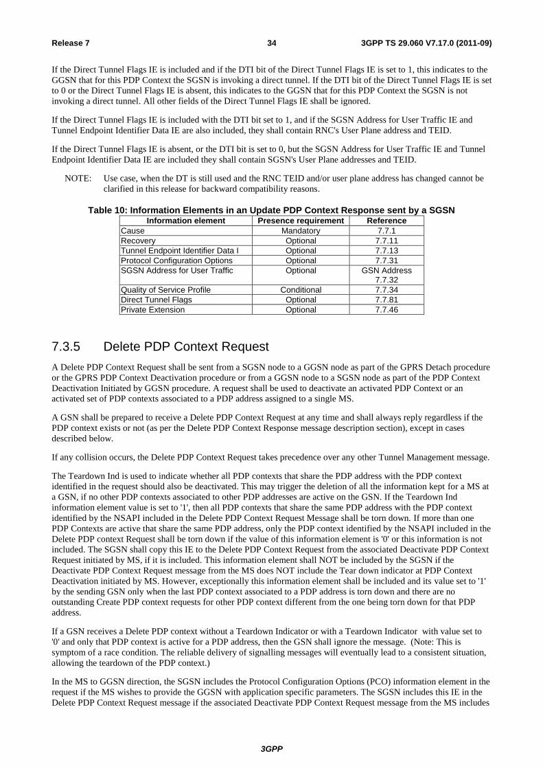
3GPP
3GPP TS 29.060 V7.17.0 (2011-09) 34 Release 7
If the Direct Tunnel Flags IE is included and if the DTI bit of the Direct Tunnel Flags IE is set to 1, this indicates to the
GGSN that for this PDP Context the SGSN is invoking a direct tunnel. If the DTI bit of the Direct Tunnel Flags IE is set
to 0 or the Direct Tunnel Flags IE is absent, this indicates to the GGSN that for this PDP Context the SGSN is not
invoking a direct tunnel. All other fields of the Direct Tunnel Flags IE shall be ignored.
If the Direct Tunnel Flags IE is included with the DTI bit set to 1, and if the SGSN Address for User Traffic IE and
Tunnel Endpoint Identifier Data IE are also included, they shall contain RNC's User Plane address and TEID.
If the Direct Tunnel Flags IE is absent, or the DTI bit is set to 0, but the SGSN Address for User Traffic IE and Tunnel
Endpoint Identifier Data IE are included they shall contain SGSN's User Plane addresses and TEID.
NOTE: Use case, when the DT is still used and the RNC TEID and/or user plane address has changed cannot be
clarified in this release for backward compatibility reasons.
Table 10: Information Elements in an Update PDP Context Response sent by a SGSNInformation element Presence requirement Reference
Cause Mandatory 7.7.1
Recovery Optional 7.7.11
Tunnel Endpoint Identifier Data I Optional 7.7.13
Protocol Configuration Options Optional 7.7.31
SGSN Address for User Traffic Optional GSN Address 7.7.32
Quality of Service Profile Conditional 7.7.34
Direct Tunnel Flags Optional 7.7.81
Private Extension Optional 7.7.46
7.3.5 Delete PDP Context Request
A Delete PDP Context Request shall be sent from a SGSN node to a GGSN node as part of the GPRS Detach procedure
or the GPRS PDP Context Deactivation procedure or from a GGSN node to a SGSN node as part of the PDP Context
Deactivation Initiated by GGSN procedure. A request shall be used to deactivate an activated PDP Context or an
activated set of PDP contexts associated to a PDP address assigned to a single MS.
A GSN shall be prepared to receive a Delete PDP Context Request at any time and shall always reply regardless if the
PDP context exists or not (as per the Delete PDP Context Response message description section), except in cases
described below.
If any collision occurs, the Delete PDP Context Request takes precedence over any other Tunnel Management message.
The Teardown Ind is used to indicate whether all PDP contexts that share the PDP address with the PDP context
identified in the request should also be deactivated. This may trigger the deletion of all the information kept for a MS at
a GSN, if no other PDP contexts associated to other PDP addresses are active on the GSN. If the Teardown Ind
information element value is set to '1', then all PDP contexts that share the same PDP address with the PDP context
identified by the NSAPI included in the Delete PDP Context Request Message shall be torn down. If more than one
PDP Contexts are active that share the same PDP address, only the PDP context identified by the NSAPI included in the
Delete PDP context Request shall be torn down if the value of this information element is '0' or this information is not
included. The SGSN shall copy this IE to the Delete PDP Context Request from the associated Deactivate PDP Context
Request initiated by MS, if it is included. This information element shall NOT be included by the SGSN if the
Deactivate PDP Context Request message from the MS does NOT include the Tear down indicator at PDP Context
Deactivation initiated by MS. However, exceptionally this information element shall be included and its value set to '1'
by the sending GSN only when the last PDP context associated to a PDP address is torn down and there are no
outstanding Create PDP context requests for other PDP context different from the one being torn down for that PDP
address.
If a GSN receives a Delete PDP context without a Teardown Indicator or with a Teardown Indicator with value set to
'0' and only that PDP context is active for a PDP address, then the GSN shall ignore the message. (Note: This is
symptom of a race condition. The reliable delivery of signalling messages will eventually lead to a consistent situation,
allowing the teardown of the PDP context.)
In the MS to GGSN direction, the SGSN includes the Protocol Configuration Options (PCO) information element in the
request if the MS wishes to provide the GGSN with application specific parameters. The SGSN includes this IE in the
Delete PDP Context Request message if the associated Deactivate PDP Context Request message from the MS includes
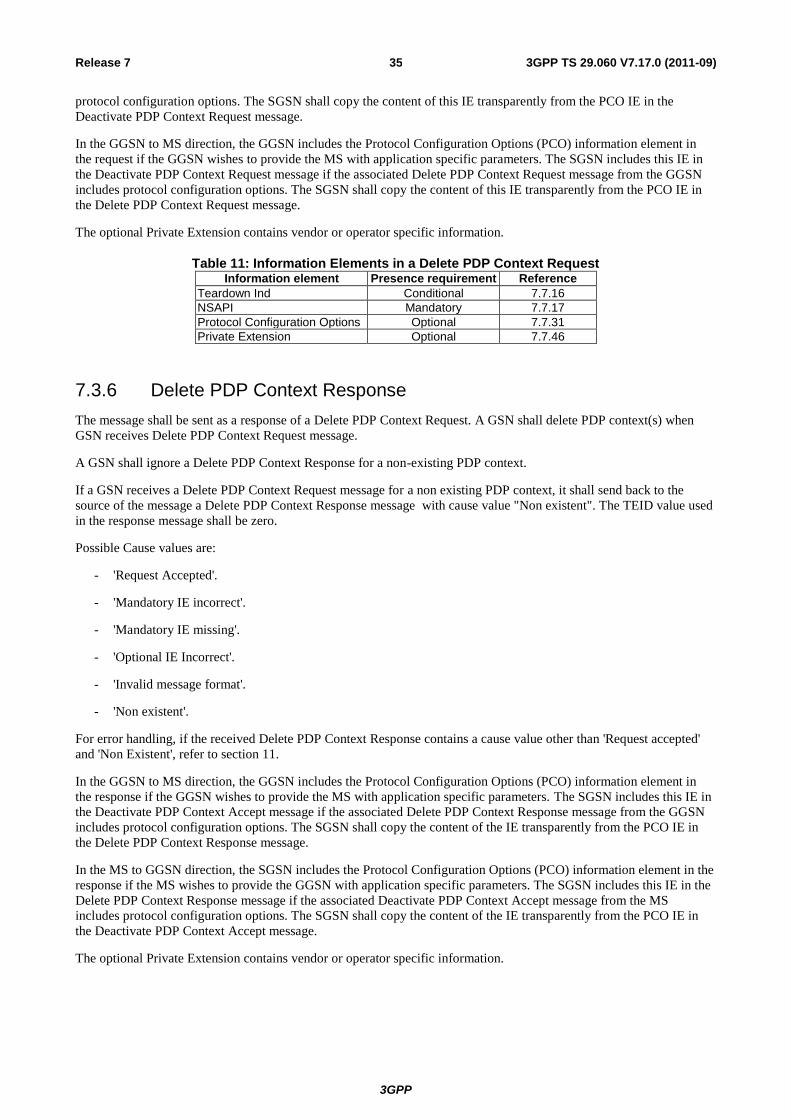
3GPP
3GPP TS 29.060 V7.17.0 (2011-09) 35 Release 7
protocol configuration options. The SGSN shall copy the content of this IE transparently from the PCO IE in the
Deactivate PDP Context Request message.
In the GGSN to MS direction, the GGSN includes the Protocol Configuration Options (PCO) information element in
the request if the GGSN wishes to provide the MS with application specific parameters. The SGSN includes this IE in
the Deactivate PDP Context Request message if the associated Delete PDP Context Request message from the GGSN
includes protocol configuration options. The SGSN shall copy the content of this IE transparently from the PCO IE in
the Delete PDP Context Request message.
The optional Private Extension contains vendor or operator specific information.
Table 11: Information Elements in a Delete PDP Context RequestInformation element Presence requirement Reference
Teardown Ind Conditional 7.7.16
NSAPI Mandatory 7.7.17
Protocol Configuration Options Optional 7.7.31
Private Extension Optional 7.7.46
7.3.6 Delete PDP Context Response
The message shall be sent as a response of a Delete PDP Context Request. A GSN shall delete PDP context(s) when
GSN receives Delete PDP Context Request message.
A GSN shall ignore a Delete PDP Context Response for a non-existing PDP context.
If a GSN receives a Delete PDP Context Request message for a non existing PDP context, it shall send back to the
source of the message a Delete PDP Context Response message with cause value "Non existent". The TEID value used
in the response message shall be zero.
Possible Cause values are:
- 'Request Accepted'.
- 'Mandatory IE incorrect'.
- 'Mandatory IE missing'.
- 'Optional IE Incorrect'.
- 'Invalid message format'.
- 'Non existent'.
For error handling, if the received Delete PDP Context Response contains a cause value other than 'Request accepted'
and 'Non Existent', refer to section 11.
In the GGSN to MS direction, the GGSN includes the Protocol Configuration Options (PCO) information element in
the response if the GGSN wishes to provide the MS with application specific parameters. The SGSN includes this IE in
the Deactivate PDP Context Accept message if the associated Delete PDP Context Response message from the GGSN
includes protocol configuration options. The SGSN shall copy the content of the IE transparently from the PCO IE in
the Delete PDP Context Response message.
In the MS to GGSN direction, the SGSN includes the Protocol Configuration Options (PCO) information element in the
response if the MS wishes to provide the GGSN with application specific parameters. The SGSN includes this IE in the
Delete PDP Context Response message if the associated Deactivate PDP Context Accept message from the MS
includes protocol configuration options. The SGSN shall copy the content of the IE transparently from the PCO IE in
the Deactivate PDP Context Accept message.
The optional Private Extension contains vendor or operator specific information.
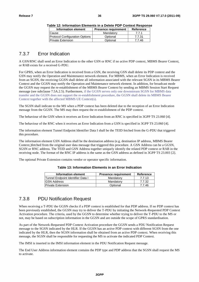
3GPP
3GPP TS 29.060 V7.17.0 (2011-09) 36 Release 7
Table 12: Information Elements in a Delete PDP Context ResponseInformation element Presence requirement Reference
Cause Mandatory 7.7.1
Protocol Configuration Options Optional 7.7.31
Private Extension Optional 7.7.46
7.3.7 Error Indication
A GSN/RNC shall send an Error Indication to the other GSN or RNC if no active PDP context, MBMS Bearer Context,
or RAB exists for a received G-PDU.
For GPRS, when an Error Indication is received from a GSN, the receiving GSN shall delete its PDP context and the
GSN may notify the Operation and Maintenance network element. For MBMS, when an Error Indication is received
from an SGSN, the receiving GGSN shall delete all information associated with the relevant SGSN in its MBMS Bearer
Context and the GGSN may notify the Operation and Maintenance network element. In addition, for broadcast mode
the GGSN may request the re-establishment of the MBMS Bearer Context by sending an MBMS Session Start Request
message (see subclause 7.5A.2.5). Furthermore, if the GGSN serves only one downstream SGSN for MBMS data
transfer and the GGSN does not support the re-establishment procedure, the GGSN shall delete its MBMS Bearer
Context together with the affected MBMS UE Context(s).
The SGSN shall indicate to the MS when a PDP context has been deleted due to the reception of an Error Indication
message from the GGSN. The MS may then request the re-establishment of the PDP context.
The behaviour of the GSN when it receives an Error Indication from an RNC is specified in 3GPP TS 23.060 [4].
The behaviour of the RNC when it receives an Error Indication from a GSN is specified in 3GPP TS 23.060 [4].
The information element Tunnel Endpoint Identifier Data I shall be the TEID fetched from the G-PDU that triggered
this procedure.
The information element GSN Address shall be the destination address (e.g. destination IP address, MBMS Bearer
Context,)fetched from the original user data message that triggered this procedure. A GSN Address can be a GGSN,
SGSN or RNC address. The TEID and GSN Address together uniquely identify the related PDP context or RAB in the
receiving node. The format of the RNC IP address is the same as the GSN address as defined in 3GPP TS 23.003 [2].
The optional Private Extension contains vendor or operator specific information.
Table 13: Information Elements in an Error Indication
Information element Presence requirement Reference
Tunnel Endpoint Identifier Data I Mandatory 7.7.13
GSN Address Mandatory 7.7.32
Private Extension Optional 7.7.46
7.3.8 PDU Notification Request
When receiving a T-PDU the GGSN checks if a PDP context is established for that PDP address. If no PDP context has
been previously established, the GGSN may try to deliver the T-PDU by initiating the Network-Requested PDP Context
Activation procedure. The criteria, used by the GGSN to determine whether trying to deliver the T-PDU to the MS or
not, may be based on subscription information in the GGSN and are outside the scope of GPRS standardisation.
As part of the Network-Requested PDP Context Activation procedure the GGSN sends a PDU Notification Request
message to the SGSN indicated by the HLR. If the GGSN has an active PDP context with different SGSN from the one
indicated by the HLR, then the SGSN information shall be obtained from an active PDP context. When receiving this
message, the SGSN shall be responsible for requesting the MS to activate the indicated PDP Context.
The IMSI is inserted in the IMSI information element in the PDU Notification Request message.
The End User Address information element contains the PDP type and PDP address that the SGSN shall request the MS
to activate.

3GPP
3GPP TS 29.060 V7.17.0 (2011-09) 37 Release 7
The Access Point Name information element identifies the access point of packet data network that wishes to connect to
the MS.
The GGSN shall include a GGSN Address for control plane. The SGSN shall store this GGSN Address and use it when
sending control plane messages to the GGSN.
The Tunnel Endpoint Identifier Control Plane information element shall be a tunnel endpoint identifier Control Plane
selected by the GGSN and shall be used by the SGSN in the GTP header of the corresponding PDU Notification
Response or PDU Notification Request Reject message.
The GGSN includes the Protocol Configuration Options (PCO) information element in the request if the GGSN wishes
to provide the MS with application specific parameters. The SGSN includes this IE in the Request PDP Context
Activation message if the associated PDU Notification Request message from the GGSN includes protocol
configuration options. The SGSN shall copy the content of the IE transparently from the PCO IE in the PDU
Notification Request message.
If the GGSN receives a Create PDP Context Request before the PDU Notification Response, the GGSN shall handle the
Create PDP Context Request as normal context activation and ignore the following PDU Notification Response.
If the SGSN receives a PDU Notification Request after a Create PDP Context Request has been sent but before a Create
PDP Context Response has been received, the SGSN shall:
- send a PDU Notification Response with Cause 'Request accepted' without any further processing; and then
- wait for the Create PDP Context Response.
The optional Private Extension contains vendor or operator specific information.
Table 14: Information Elements in a PDU Notification Request
Information element Presence requirement Reference
IMSI Mandatory 7.7.2
Tunnel Endpoint Identifier Control Plane Mandatory 7.7.14
End User Address Mandatory 7.7.27
Access Point Name Mandatory 7.7.30
Protocol Configuration Options Optional 7.7.31
GGSN Address for Control Plane Mandatory 7.7.32
Private Extension Optional 7.7.46
7.3.9 PDU Notification Response
The message is sent by a SGSN to GGSN as a response of a PDU Notification Request.
The Cause value 'Request accepted' indicates if the PDP context activation will proceed. The PDP context activation
procedure will not proceed for other Cause values.
Possible Cause values are:
- 'Request Accepted'.
- 'No resources available'.
- 'Service not supported'.
- 'System failure'.
- 'IMSI not known'.
- 'MS is GPRS Detached'.
- 'GPRS connection suspended'.
- 'Mandatory IE incorrect'.
- 'Mandatory IE missing'.

3GPP
3GPP TS 29.060 V7.17.0 (2011-09) 38 Release 7
- 'Optional IE incorrect'.
- 'Invalid message format'.
- 'Roaming restriction'.
After an unsuccessful activation attempt the GSNs may perform some actions to prevent unnecessary enquires to the
HLR as described in the section Unsuccessful Network-Requested PDP Context Activation procedure in
3GPP TS 23.060 [4].
The optional Private Extension contains vendor or operator specific information.
Table 15: Information Elements in a PDU Notification Response
Information element Presence requirement Reference
Cause Mandatory 7.7.1
Private Extension Optional 7.7.46
7.3.10 PDU Notification Reject Request
If the PDP context activation proceeds after the PDU Notification Response, but the PDP context was not established,
the SGSN sends a PDU Notification Reject Request message. The Cause value indicates the reason why the PDP
Context could not be established:
- 'MS is not GPRS Responding'.
- 'MS Refuses'.
When receiving the PDU Notification Reject Request message the GGSN may reject or discard the stored T-PDU(s)
depending on the PDP type.
After an unsuccessful activation attempt the GSNs may perform some actions to prevent unnecessary enquiries to the
HLR as described in the section Unsuccessful Network-Requested PDP Context Activation procedure in 3GPP TS
23.060 [4].
The Tunnel Endpoint Identifier in the GTP header of the PDU Notification Reject Request message shall be the same as
the Tunnel Endpoint Identifier Control Plane information element of the PDU Notification Request that triggered the
reject.
The Tunnel Endpoint Identifier Control Plane information element shall be a tunnel endpoint identifier Control Plane
selected by the SGSN and shall be used by the GGSN in the GTP header of the corresponding PDU Notification Reject
Response message.
The End User Address information element contains the PDP type and PDP address of the PDP context that could not
be activated.
The Access Point Name shall be the same as the Access Point Name of the received PDU Notification Request message
that triggered the reject.
The SGSN includes the Protocol Configuration Options (PCO) information element in the request if the MS wishes to
provide the GGSN with application specific parameters. The SGSN includes this IE in the PDU Notification Reject
Request message if the associated Request PDP Context Activation Reject message from the MS includes protocol
configuration options. The SGSN shall copy the content of the IE transparently from the PCO IE in the Request PDP
Context Activation Reject message.
The optional Private Extension contains vendor or operator specific information.
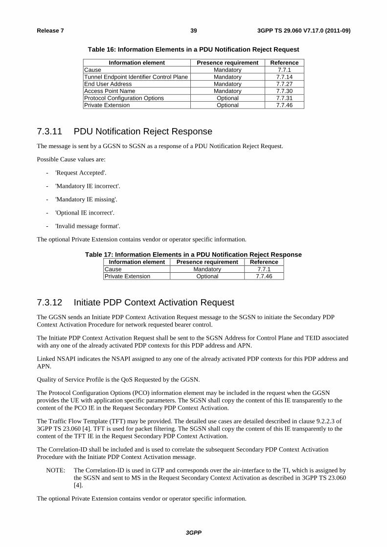
3GPP
3GPP TS 29.060 V7.17.0 (2011-09) 39 Release 7
Table 16: Information Elements in a PDU Notification Reject Request
Information element Presence requirement Reference
Cause Mandatory 7.7.1
Tunnel Endpoint Identifier Control Plane Mandatory 7.7.14
End User Address Mandatory 7.7.27
Access Point Name Mandatory 7.7.30
Protocol Configuration Options Optional 7.7.31
Private Extension Optional 7.7.46
7.3.11 PDU Notification Reject Response
The message is sent by a GGSN to SGSN as a response of a PDU Notification Reject Request.
Possible Cause values are:
- 'Request Accepted'.
- 'Mandatory IE incorrect'.
- 'Mandatory IE missing'.
- 'Optional IE incorrect'.
- 'Invalid message format'.
The optional Private Extension contains vendor or operator specific information.
Table 17: Information Elements in a PDU Notification Reject ResponseInformation element Presence requirement Reference
Cause Mandatory 7.7.1
Private Extension Optional 7.7.46
7.3.12 Initiate PDP Context Activation Request
The GGSN sends an Initiate PDP Context Activation Request message to the SGSN to initiate the Secondary PDP
Context Activation Procedure for network requested bearer control.
The Initiate PDP Context Activation Request shall be sent to the SGSN Address for Control Plane and TEID associated
with any one of the already activated PDP contexts for this PDP address and APN.
Linked NSAPI indicates the NSAPI assigned to any one of the already activated PDP contexts for this PDP address and
APN.
Quality of Service Profile is the QoS Requested by the GGSN.
The Protocol Configuration Options (PCO) information element may be included in the request when the GGSN
provides the UE with application specific parameters. The SGSN shall copy the content of this IE transparently to the
content of the PCO IE in the Request Secondary PDP Context Activation.
The Traffic Flow Template (TFT) may be provided. The detailed use cases are detailed described in clause 9.2.2.3 of
3GPP TS 23.060 [4]. TFT is used for packet filtering. The SGSN shall copy the content of this IE transparently to the
content of the TFT IE in the Request Secondary PDP Context Activation.
The Correlation-ID shall be included and is used to correlate the subsequent Secondary PDP Context Activation
Procedure with the Initiate PDP Context Activation message.
NOTE: The Correlation-ID is used in GTP and corresponds over the air-interface to the TI, which is assigned by
the SGSN and sent to MS in the Request Secondary Context Activation as described in 3GPP TS 23.060
[4].
The optional Private Extension contains vendor or operator specific information.

3GPP
3GPP TS 29.060 V7.17.0 (2011-09) 40 Release 7
Table 7.3.12.1: Information Elements in an Initiate PDP Context Activation Request
Information element Presence requirement Reference
Linked NSAPI Mandatory 7.7.17
Protocol Configuration Options Optional 7.7.31
Quality of Service Profile Mandatory 7.7.34
TFT Conditional 7.7.36
Correlation-ID Mandatory 7.7.82
Private Extension Optional 7.7.46
7.3.13 Initiate PDP Context Activation Response
The message is sent by a SGSN to GGSN as a response of an Initiate PDP Context Activation Request message after
the SGSN receives from the UE either a positive acknowledgment (Activate Secondary PDP Context Request message)
or a negative acknowledgment (Secondary PDP Context Activation Reject message), or if SGSN does not receive any
response from the UE before the Radio Interface timer T3385 expires (see TS 24.008 [5]). If the PDP context was not
established, the SGSN includes a Cause Code to indicate the reason why the PDP Context could not be established.
The Cause value 'Request accepted' indicates that the Initiate PDP Context Activation was successful. The Initiate PDP
Context Activation procedure was not successful for other Cause values.
Possible Cause values are:
- 'Request Accepted'.
- 'No resources available'.
- 'Service not supported'.
- 'System failure'.
- 'Mandatory IE incorrect'.
- 'Mandatory IE missing'.
- 'Optional IE incorrect'.
- 'Invalid message format'.
- 'Context not found'.
- 'Semantic error in the TFT operation',
- 'Syntactic error in the TFT operation',
- 'Semantic errors in packet filter(s)'
- 'Syntactic errors in packet filters(s)'
- 'MS is not GPRS Responding'.
- 'MS Refuses'.
- 'Invalid Correlation-ID'.
The SGSN includes the Protocol Configuration Options (PCO) information element in the response if the MS wishes to
provide the GGSN with application specific parameters. The SGSN includes this IE in the Initiate PDP Context
Activation Response message if the Request PDP Context Activation Reject message from the MS includes protocol
configuration options. The SGSN shall copy the content of the IE transparently from the PCO IE in the Request PDP
Context Activation Reject message. The optional Private Extension contains vendor or operator specific information.
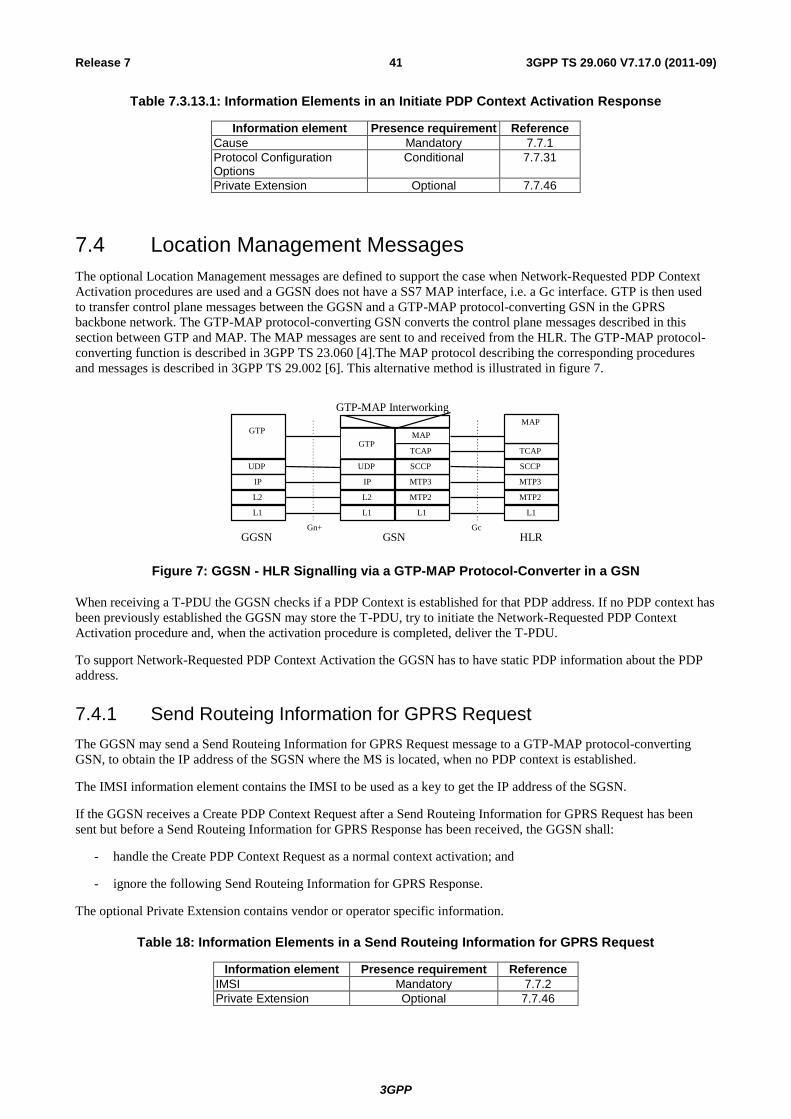
3GPP
3GPP TS 29.060 V7.17.0 (2011-09) 41 Release 7
Table 7.3.13.1: Information Elements in an Initiate PDP Context Activation Response
Information element Presence requirement Reference
Cause Mandatory 7.7.1
Protocol Configuration Options
Conditional 7.7.31
Private Extension Optional 7.7.46
7.4 Location Management Messages
The optional Location Management messages are defined to support the case when Network-Requested PDP Context
Activation procedures are used and a GGSN does not have a SS7 MAP interface, i.e. a Gc interface. GTP is then used
to transfer control plane messages between the GGSN and a GTP-MAP protocol-converting GSN in the GPRS
backbone network. The GTP-MAP protocol-converting GSN converts the control plane messages described in this
section between GTP and MAP. The MAP messages are sent to and received from the HLR. The GTP-MAP protocol-
converting function is described in 3GPP TS 23.060 [4].The MAP protocol describing the corresponding procedures
and messages is described in 3GPP TS 29.002 [6]. This alternative method is illustrated in figure 7.
Gn+
UDP
L2 IP
GGSN
L1 L2 IP
UDP
GSN
GTP
L1 MTP2 MTP3 SCCP TCAP MAP
L1 MTP2 MTP3 SCCP
HLR
TCAP
MAP
L1
GTP
Gc
GTP-MAP Interworking
Figure 7: GGSN - HLR Signalling via a GTP-MAP Protocol-Converter in a GSN
When receiving a T-PDU the GGSN checks if a PDP Context is established for that PDP address. If no PDP context has
been previously established the GGSN may store the T-PDU, try to initiate the Network-Requested PDP Context
Activation procedure and, when the activation procedure is completed, deliver the T-PDU.
To support Network-Requested PDP Context Activation the GGSN has to have static PDP information about the PDP
address.
7.4.1 Send Routeing Information for GPRS Request
The GGSN may send a Send Routeing Information for GPRS Request message to a GTP-MAP protocol-converting
GSN, to obtain the IP address of the SGSN where the MS is located, when no PDP context is established.
The IMSI information element contains the IMSI to be used as a key to get the IP address of the SGSN.
If the GGSN receives a Create PDP Context Request after a Send Routeing Information for GPRS Request has been
sent but before a Send Routeing Information for GPRS Response has been received, the GGSN shall:
- handle the Create PDP Context Request as a normal context activation; and
- ignore the following Send Routeing Information for GPRS Response.
The optional Private Extension contains vendor or operator specific information.
Table 18: Information Elements in a Send Routeing Information for GPRS Request
Information element Presence requirement Reference
IMSI Mandatory 7.7.2
Private Extension Optional 7.7.46
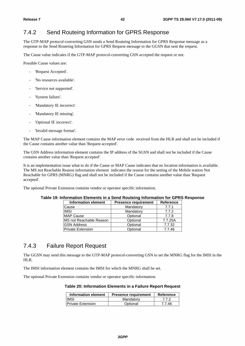
3GPP
3GPP TS 29.060 V7.17.0 (2011-09) 42 Release 7
7.4.2 Send Routeing Information for GPRS Response
The GTP-MAP protocol-converting GSN sends a Send Routeing Information for GPRS Response message as a
response to the Send Routeing Information for GPRS Request message to the GGSN that sent the request.
The Cause value indicates if the GTP-MAP protocol-converting GSN accepted the request or not.
Possible Cause values are:
- 'Request Accepted'.
- 'No resources available'.
- 'Service not supported'.
- 'System failure'.
- 'Mandatory IE incorrect'.
- 'Mandatory IE missing'.
- 'Optional IE incorrect'.
- 'Invalid message format'.
The MAP Cause information element contains the MAP error code received from the HLR and shall not be included if
the Cause contains another value than 'Request accepted'.
The GSN Address information element contains the IP address of the SGSN and shall not be included if the Cause
contains another value than 'Request accepted'.
It is an implementation issue what to do if the Cause or MAP Cause indicates that no location information is available.
The MS not Reachable Reason information element indicates the reason for the setting of the Mobile station Not
Reachable for GPRS (MNRG) flag and shall not be included if the Cause contains another value than 'Request
accepted'.
The optional Private Extension contains vendor or operator specific information.
Table 19: Information Elements in a Send Routeing Information for GPRS ResponseInformation element Presence requirement Reference
Cause Mandatory 7.7.1
IMSI Mandatory 7.7.2
MAP Cause Optional 7.7.8
MS not Reachable Reason Optional 7.7.25A
GSN Address Optional 7.7.32
Private Extension Optional 7.7.46
7.4.3 Failure Report Request
The GGSN may send this message to the GTP-MAP protocol-converting GSN to set the MNRG flag for the IMSI in the
HLR.
The IMSI information element contains the IMSI for which the MNRG shall be set.
The optional Private Extension contains vendor or operator specific information.
Table 20: Information Elements in a Failure Report Request
Information element Presence requirement Reference
IMSI Mandatory 7.7.2
Private Extension Optional 7.7.46
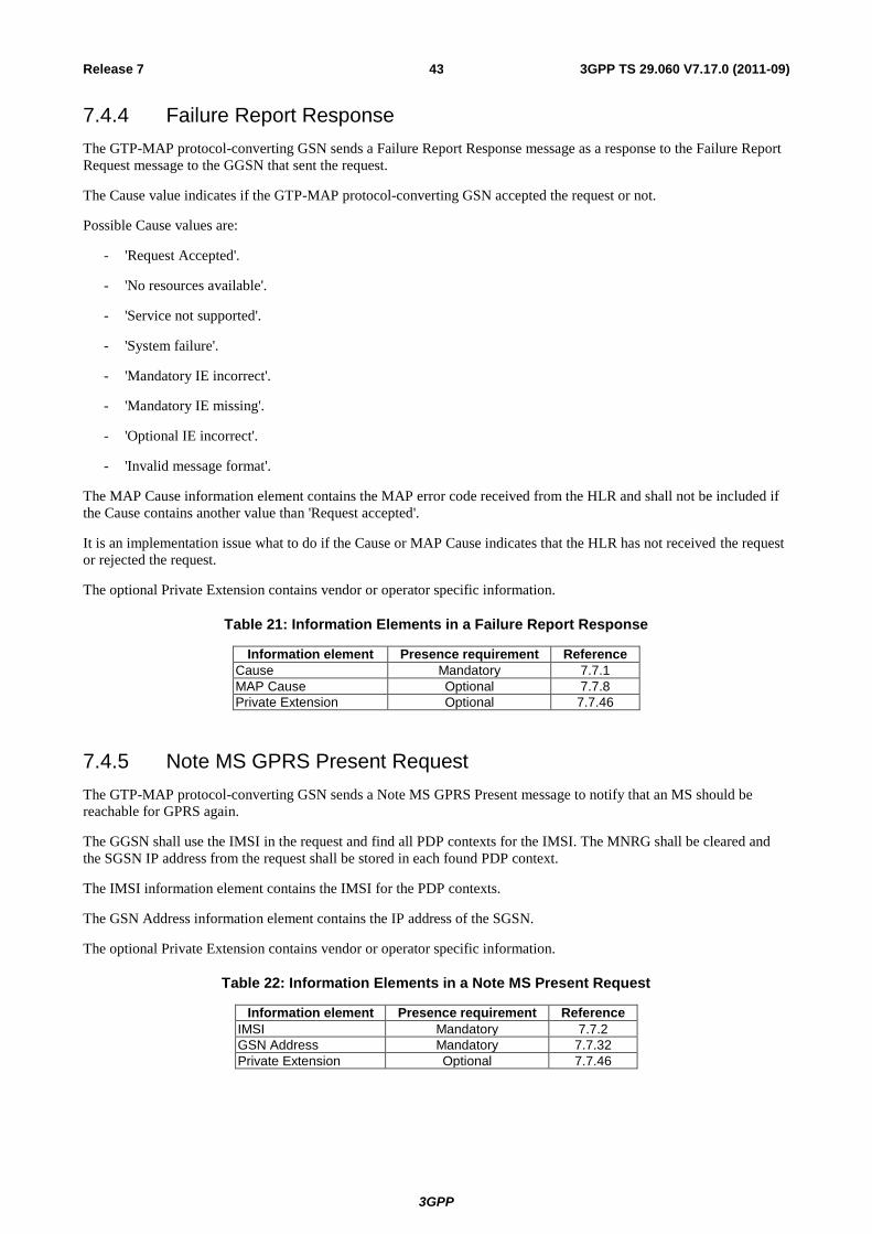
3GPP
3GPP TS 29.060 V7.17.0 (2011-09) 43 Release 7
7.4.4 Failure Report Response
The GTP-MAP protocol-converting GSN sends a Failure Report Response message as a response to the Failure Report
Request message to the GGSN that sent the request.
The Cause value indicates if the GTP-MAP protocol-converting GSN accepted the request or not.
Possible Cause values are:
- 'Request Accepted'.
- 'No resources available'.
- 'Service not supported'.
- 'System failure'.
- 'Mandatory IE incorrect'.
- 'Mandatory IE missing'.
- 'Optional IE incorrect'.
- 'Invalid message format'.
The MAP Cause information element contains the MAP error code received from the HLR and shall not be included if
the Cause contains another value than 'Request accepted'.
It is an implementation issue what to do if the Cause or MAP Cause indicates that the HLR has not received the request
or rejected the request.
The optional Private Extension contains vendor or operator specific information.
Table 21: Information Elements in a Failure Report Response
Information element Presence requirement Reference
Cause Mandatory 7.7.1
MAP Cause Optional 7.7.8
Private Extension Optional 7.7.46
7.4.5 Note MS GPRS Present Request
The GTP-MAP protocol-converting GSN sends a Note MS GPRS Present message to notify that an MS should be
reachable for GPRS again.
The GGSN shall use the IMSI in the request and find all PDP contexts for the IMSI. The MNRG shall be cleared and
the SGSN IP address from the request shall be stored in each found PDP context.
The IMSI information element contains the IMSI for the PDP contexts.
The GSN Address information element contains the IP address of the SGSN.
The optional Private Extension contains vendor or operator specific information.
Table 22: Information Elements in a Note MS Present Request
Information element Presence requirement Reference
IMSI Mandatory 7.7.2
GSN Address Mandatory 7.7.32
Private Extension Optional 7.7.46
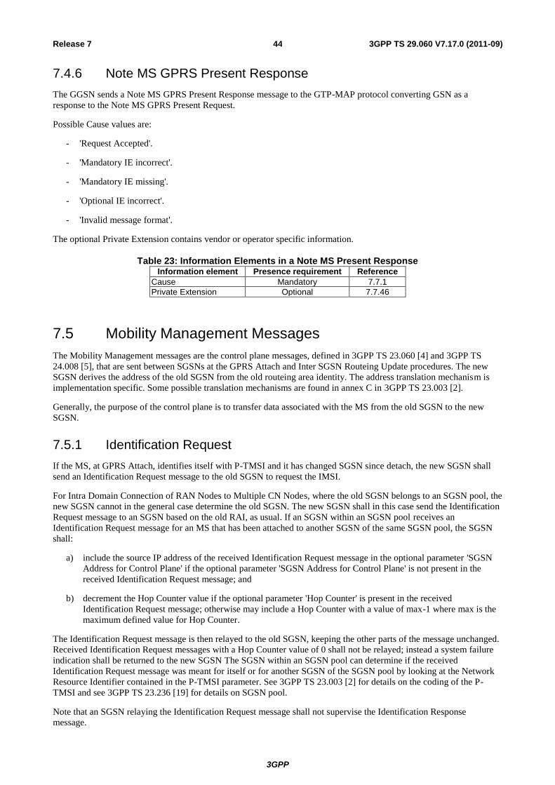
3GPP
3GPP TS 29.060 V7.17.0 (2011-09) 44 Release 7
7.4.6 Note MS GPRS Present Response
The GGSN sends a Note MS GPRS Present Response message to the GTP-MAP protocol converting GSN as a
response to the Note MS GPRS Present Request.
Possible Cause values are:
- 'Request Accepted'.
- 'Mandatory IE incorrect'.
- 'Mandatory IE missing'.
- 'Optional IE incorrect'.
- 'Invalid message format'.
The optional Private Extension contains vendor or operator specific information.
Table 23: Information Elements in a Note MS Present ResponseInformation element Presence requirement Reference
Cause Mandatory 7.7.1
Private Extension Optional 7.7.46
7.5 Mobility Management Messages
The Mobility Management messages are the control plane messages, defined in 3GPP TS 23.060 [4] and 3GPP TS
24.008 [5], that are sent between SGSNs at the GPRS Attach and Inter SGSN Routeing Update procedures. The new
SGSN derives the address of the old SGSN from the old routeing area identity. The address translation mechanism is
implementation specific. Some possible translation mechanisms are found in annex C in 3GPP TS 23.003 [2].
Generally, the purpose of the control plane is to transfer data associated with the MS from the old SGSN to the new
SGSN.
7.5.1 Identification Request
If the MS, at GPRS Attach, identifies itself with P-TMSI and it has changed SGSN since detach, the new SGSN shall
send an Identification Request message to the old SGSN to request the IMSI.
For Intra Domain Connection of RAN Nodes to Multiple CN Nodes, where the old SGSN belongs to an SGSN pool, the
new SGSN cannot in the general case determine the old SGSN. The new SGSN shall in this case send the Identification
Request message to an SGSN based on the old RAI, as usual. If an SGSN within an SGSN pool receives an
Identification Request message for an MS that has been attached to another SGSN of the same SGSN pool, the SGSN
shall:
a) include the source IP address of the received Identification Request message in the optional parameter 'SGSN
Address for Control Plane' if the optional parameter 'SGSN Address for Control Plane' is not present in the
received Identification Request message; and
b) decrement the Hop Counter value if the optional parameter 'Hop Counter' is present in the received
Identification Request message; otherwise may include a Hop Counter with a value of max-1 where max is the
maximum defined value for Hop Counter.
The Identification Request message is then relayed to the old SGSN, keeping the other parts of the message unchanged.
Received Identification Request messages with a Hop Counter value of 0 shall not be relayed; instead a system failure
indication shall be returned to the new SGSN The SGSN within an SGSN pool can determine if the received
Identification Request message was meant for itself or for another SGSN of the SGSN pool by looking at the Network
Resource Identifier contained in the P-TMSI parameter. See 3GPP TS 23.003 [2] for details on the coding of the P-
TMSI and see 3GPP TS 23.236 [19] for details on SGSN pool.
Note that an SGSN relaying the Identification Request message shall not supervise the Identification Response
message.
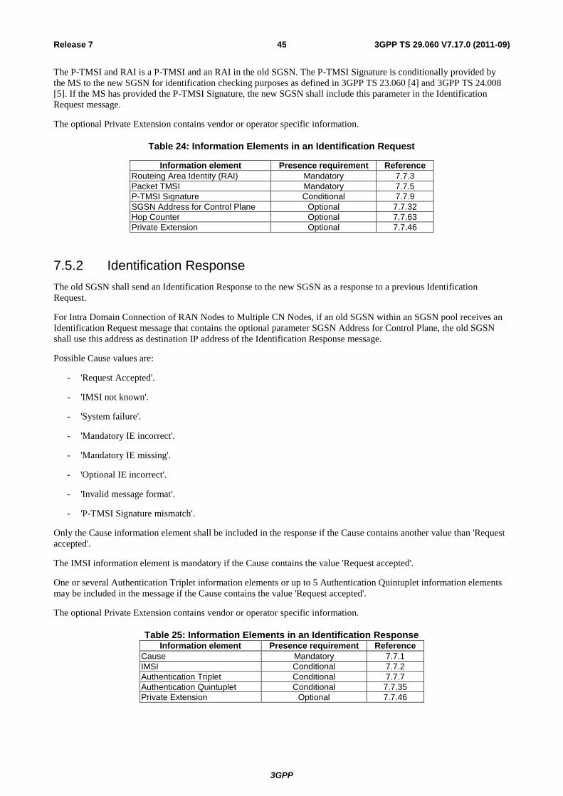
3GPP
3GPP TS 29.060 V7.17.0 (2011-09) 45 Release 7
The P-TMSI and RAI is a P-TMSI and an RAI in the old SGSN. The P-TMSI Signature is conditionally provided by
the MS to the new SGSN for identification checking purposes as defined in 3GPP TS 23.060 [4] and 3GPP TS 24.008
[5]. If the MS has provided the P-TMSI Signature, the new SGSN shall include this parameter in the Identification
Request message.
The optional Private Extension contains vendor or operator specific information.
Table 24: Information Elements in an Identification Request
Information element Presence requirement Reference
Routeing Area Identity (RAI) Mandatory 7.7.3
Packet TMSI Mandatory 7.7.5
P-TMSI Signature Conditional 7.7.9
SGSN Address for Control Plane Optional 7.7.32
Hop Counter Optional 7.7.63
Private Extension Optional 7.7.46
7.5.2 Identification Response
The old SGSN shall send an Identification Response to the new SGSN as a response to a previous Identification
Request.
For Intra Domain Connection of RAN Nodes to Multiple CN Nodes, if an old SGSN within an SGSN pool receives an
Identification Request message that contains the optional parameter SGSN Address for Control Plane, the old SGSN
shall use this address as destination IP address of the Identification Response message.
Possible Cause values are:
- 'Request Accepted'.
- 'IMSI not known'.
- 'System failure'.
- 'Mandatory IE incorrect'.
- 'Mandatory IE missing'.
- 'Optional IE incorrect'.
- 'Invalid message format'.
- 'P-TMSI Signature mismatch'.
Only the Cause information element shall be included in the response if the Cause contains another value than 'Request
accepted'.
The IMSI information element is mandatory if the Cause contains the value 'Request accepted'.
One or several Authentication Triplet information elements or up to 5 Authentication Quintuplet information elements
may be included in the message if the Cause contains the value 'Request accepted'.
The optional Private Extension contains vendor or operator specific information.
Table 25: Information Elements in an Identification ResponseInformation element Presence requirement Reference
Cause Mandatory 7.7.1
IMSI Conditional 7.7.2
Authentication Triplet Conditional 7.7.7
Authentication Quintuplet Conditional 7.7.35
Private Extension Optional 7.7.46
3GPP
3GPP TS 29.060 V7.17.0 (2011-09) 46 Release 7
7.5.3 SGSN Context Request
The new SGSN shall send an SGSN Context Request to the old SGSN to get the MM and PDP Contexts for the MS.
For Intra Domain Connection of RAN Nodes to Multiple CN Nodes, where the old SGSN belongs to an SGSN pool,
the new SGSN cannot in the general case determine the old SGSN. The new SGSN shall in this case send the SGSN
Context Request message to an SGSN based on the old RAI, as usual. If an SGSN within an SGSN pool receives an
SGSN Context Request message for an MS that has been attached to another SGSN of the same SGSN pool, the SGSN
shall:
if the optional parameter 'Hop Counter' is present in the received SGSN Context Request message, decrement the Hop
Counter value, otherwise may include a Hop Counter with a value of max-1 where max is the maximum defined value
for Hop Counter;
the SGSN Context Request message is then relayed to the old SGSN, keeping the other parts of the message
unchanged. Received SGSN Context Request messages with a Hop Counter value of 0 shall not be relayed; instead a
system failure indication shall be returned to the new SGSN. The SGSN within an SGSN pool can determine if the
received SGSN Context Request message was meant for itself or for another SGSN of the SGSN pool by looking at the
Network Resource Identifier contained in the P-TMSI parameter, or alternatively in the TLLI parameter. See 3GPP TS
23.003 [2] for details on the coding of the P-TMSI and see 3GPP TS 23.236 [19] for details on SGSN pool.
Note that an SGSN relaying the SGSN Context Request message shall not supervise the SGSN Context Response
message.
The MS is identified in the old SGSN by its old RAI and old TLLI/old P-TMSI values. The TLLI/P-TMSI and RAI is a
foreign TLLI/P-TMSI and an RAI in the old SGSN. Exactly one of the TLLI, P-TMSI or IMSI information fields shall
be present.
The old SGSN responds with an SGSN Context Response.
The new SGSN shall include a SGSN Address for control plane. If the new SGSN is IPv4/ IPv6 capable, it shall include
IPv4 address in the field of SGSN Address for Control Plane and IPv6 address in the field of Alternative SGSN Address
for Control Plane. If the old SGSN is IPv6 capable, it shall store and use the IPv6 SGSN address when sending control
plane messages for the MS to the new SGSN in the SGSN context transfer procedure. Otherwise if the old SGSN is
only IPv4 capable, it shall store and use the IPv4 SGSN address in the SGSN context transfer procedure. The old SGSN
shall store this SGSN Address and use it when sending control plane messages for the MS to the new SGSN in the
SGSN context transfer procedure
The new SGSN may include its SGSN number. If the old SGSN receives the SGSN number of the new SGSN it shall
include this number when informing interworking core network nodes that there is a need to re-route previously sent
requests against the new SGSN, e.g. in LCS the GMLC will use this SGSN number to re-activate the Location Request
to the new SGSN (3GPP TS 23.271 [24])..
The Tunnel Endpoint Identifier Control Plane field specifies a Tunnel Endpoint Identifier for control plane messages,
which is chosen by the new SGSN. The old SGSN shall include this Tunnel Endpoint Identifier in the GTP header of all
subsequent control plane messages that are sent from the old SGSN to the new SGSN and related to the PDP context(s)
requested.
The MS Validated indicates that the new SGSN has successfully authenticated the MS. IMSI shall be included if MS
Validated indicates 'Yes'.
The P-TMSI Signature is conditionally provided by the MS to the new SGSN for identification checking purposes as
defined in 3GPP TS 23.060 [4] and 3GPP TS 24.008 [5]. If the MS has provided the P-TMSI Signature, the new SGSN
shall include this parameter in the SGSN Context Request message.
The RAT Type indicates the Radio Access Technology which is used in the new SGSN.
The optional Private Extension contains vendor or operator specific information.

3GPP
3GPP TS 29.060 V7.17.0 (2011-09) 47 Release 7
Table 26: Information Elements in a SGSN Context RequestInformation element Presence requirement Reference
IMSI Conditional 7.7.2
Routeing Area Identity (RAI) Mandatory 7.7.3
Temporary Logical Link Identifier (TLLI) Conditional 7.7.4
Packet TMSI (P-TMSI) Conditional 7.7.5
P-TMSI Signature Conditional 7.7.9
MS Validated Optional 7.7.10
Tunnel Endpoint Identifier Control Plane Mandatory 7.7.14
SGSN Address for Control Plane Mandatory 7.7.32
Alternative SGSN Address for Control Plane
Optional 7.7.32
SGSN Number Optional 7.7.47
RAT Type Optional 7.7.50
Hop Counter Optional 7.7.63
Private Extension Optional 7.7.46
7.5.4 SGSN Context Response
The old SGSN shall send an SGSN Context Response to the new SGSN as a response to a previous SGSN Context
Request.
Possible Cause values are:
- 'Request Accepted'.
- 'IMSI not known'.
- 'System failure'.
- 'Mandatory IE incorrect'.
- 'Mandatory IE missing'.
- 'Optional IE incorrect'.
- 'Invalid message format'.
- 'P-TMSI Signature mismatch'.
If the Cause contains the value 'Request accepted', all information elements are mandatory, except PDP Context,
MBMS UE Context, RAB Context and Private Extension.
If the Cause contains the value 'P-TMSI Signature mismatch' the IMSI information element and, for Intra Domain
Connection of RAN Nodes to Multiple CN Nodes, a SGSN Address for control plane shall be included in the response,
otherwise only the Cause information element shall be included in the response.
The old SGSN shall include a SGSN Address for control plane. If the SGSN Context Request received from the new
SGSN includes an IPv6 SGSN address, an IPv4/IPv6 capable old SGSN shall include IPv6 address in the field of SGSN
address for control plane; Otherwise it shall include IPv4 address in this field.The new SGSN shall store this SGSN
Address and use it when sending control plane messages for the MS to the old SGSN in the SGSN context transfer
procedure.
The Tunnel Endpoint Identifier Control Plane field specifies a Tunnel Endpoint Identifier, which is chosen by the old
SGSN. The new SGSN shall include this Tunnel Endpoint Identifier in the GTP header of all subsequent control plane
messages, which are sent from the new SGSN to the old SGSN and related to the PDP context(s) requested.
The IMSI information element contains the IMSI matching the TLLI or P-TMSI (for GSM or UMTS respectively) and
RAI in the SGSN Context Request.
The MM Context contains necessary mobility management and security parameters. The IMEISV shall, if available, be
included in the MM Context from the old SGSN to the new SGSN.

3GPP
3GPP TS 29.060 V7.17.0 (2011-09) 48 Release 7
All active PDP contexts in the old SGSN shall be included as PDP Context information elements. The PDP contexts are
included in an implementation dependant prioritized order, and the most important PDP context is placed first. When
the PDP Context Prioritization IE is included, it informs the new SGSN that the PDP contexts are sent prioritized. If the
new SGSN is not able to maintain active all the PDP contexts received from the old SGSN when it is indicated that
prioritization of the PDP contexts is applied, the new SGSN should use the prioritisation sent by old SGSN as input
when deciding which PDP contexts to maintain active and which ones to delete.
If there is at least one active PDP context, the old SGSN shall start the T3-TUNNEL timer and store the address of the
new SGSN in the "New SGSN Address" field of the MM context. The old SGSN shall wait for SGSN Context
Acknowledge before sending T-PDUs to the new SGSN. If an SGSN Context Acknowledge message is not received
within a time defined by T3-RESPONSE, the old SGSN shall retransmit the SGSN Context Response to the new SGSN
as long as the total number of attempts is less than N3-REQUESTS. After N3-REQUESTS unsuccessfully attempts, the
old SGSN shall proceed as described in section 'Reliable delivery of signalling messages' in case the transmission of a
control plane message fails N3-REQUESTS times.
For each RAB using lossless PDCP context, the old SGSN shall include a RAB Context. If a RAB Context is included
in the SGSN Context Response, the new SGSN shall ignore the N-PDU number fields and sequence number fields
received in the PDP Context IE.
Radio Priority SMS contains the radio priority level for MO SMS transmission, and shall be included if a valid Radio
Priority SMS value exists for the MS in the old SGSN.
Radio Priority LCS contains the radio priority level for MO LCS transmission, and shall be included if a valid Radio
Priority LCS value exists for the MS in the old SGSN.
Radio Priority is the radio priority level that the MS uses when accessing the network for the transmission of uplink
user data for a particular PDP context. One Radio Priority IE shall be included per PDP context that has a valid radio
priority value assigned to it in the old SGSN.
Packet Flow Id is the packet flow identifier assigned to the PDP context. One Packet Flow Id IE shall be included per
PDP context that has a valid packet flow identifier value assigned to it in the old SGSN.
Charging Characteristics IE contains the charging characteristics which apply for a PDP context; see 3GPP TS 32.251
[18] and 3GPP TS 32.298 [34]. One Charging Characteristics IE shall be included per PDP context IE. If no PDP
context is active, this IE shall not be included. The mapping of a Charging Characteristics IE to a PDP Context IE is
done according to the sequence of their appearance, e.g. the first Charging Characteristics IE is mapped to the first PDP
Context IE.
All MBMS UE Contexts in the old SGSN shall be included as MBMS UE Context information elements if the new
SGSN supports MBMS (i.e. MBMS support indication has been sent from the new SGSN).
The optional Private Extension contains vendor or operator specific information.
Table 27: Information Elements in a SGSN Context Response
Information element Presence requirement Reference
Cause Mandatory 7.7.1
IMSI Conditional 7.7.2
Tunnel Endpoint Identifier Control Plane Conditional 7.7.14
RAB Context Conditional 7.7.19
Radio Priority SMS Optional 7.7.20
Radio Priority Optional 7.7.21
Packet Flow Id Optional 7.7.22
CharingCharacteristics Optional 7.7.23
Radio Priority LCS Optional 7.7.25B
MM Context Conditional 7.7.28
PDP Context Conditional 7.7.29
SGSN Address for Control Plane Conditional 7.7.32
PDP Context Prioritization Optional 7.7.45
MBMS UE Context Optional 7.7.55
Private Extension Optional 7.7.46

3GPP
3GPP TS 29.060 V7.17.0 (2011-09) 49 Release 7
7.5.5 SGSN Context Acknowledge
The new SGSN shall send an SGSN Context Acknowledge message to the old SGSN as a response to the SGSN
Context Response message. Only after receiving the SGSN Context Acknowledge message, shall the old SGSN start to
forward user data packets. SGSN Context Acknowledge indicates to the old SGSN that the new SGSN has correctly
received PDP Context information and is ready to receive user data packets identified by the corresponding Tunnel
Endpoint Identifier values. This message shall not be sent if the SGSN Context Request was rejected.
Possible cause values are:
- 'Request accepted'.
- 'System failure'.
- 'Mandatory IE incorrect'.
- 'Mandatory IE missing'.
- 'Optional IE incorrect'.
- 'No resources available'.
- 'Invalid message format'.
- 'Authentication failure'.
Only the Cause information element shall be included in the acknowledgement if the Cause contains a value other than
'Request accepted'.
For each active PDP context (i.e. those which have a tunnel established between the old SGSN and the GGSN) the new
SGSN shall include a Tunnel Endpoint Identifier Data II information element. The Tunnel Endpoint Identifier Data II
field specifies a Tunnel Endpoint Identifier which is chosen by the new SGSN for a particular PDP context. The old
SGSN shall include this Tunnel Endpoint Identifier in the GTP header of all subsequent G-PDUs which are sent from
the old SGSN to the new SGSN and related to the particular PDP context. When active PDP context(s) exist, this
information element shall be included if the Cause contains the value 'Request accepted'.
The new SGSN shall include an SGSN Address for user traffic, which may differ from that provided by the underlying
network service (e.g. IP). If the SGSN Context Response received from the old SGSN includes an IPv6 SGSN address,
an IPv4/IPv6 capable new SGSN shall include an IPv6 address in the field of SGSN Address for user traffic, Otherwise
it shall include IPv4 address in this field . The old SGSN shall store this SGSN Address and use it when sending G-
PDUs to the new SGSN for the MS. When active PDP context(s) exist, this information element shall be included if the
Cause contains the value 'Request accepted'.
The optional Private Extension contains vendor or operator specific information.
Table 28: Information Elements in a SGSN Context Acknowledge
Information element Presence requirement Reference
Cause Mandatory 7.7.1
Tunnel Endpoint Identifier Data II Conditional 7.7.15
SGSN Address for user traffic Conditional GSN Address 7.7.32
Private Extension Optional 7.7.46
7.5.6 Forward Relocation Request
The old SGSN shall send a Forward Relocation Request to the new SGSN to convey necessary information to perform
the SRNS Relocation procedure between new SGSN and Target RNC or to perform the PS handover procedure between
new SGSN and Target BSS.
The IMSI information element contains the IMSI of the target MS for SRNS Relocation or PS handover procedure.
The old SGSN shall include a SGSN Address for control plane. The new SGSN shall store this SGSN Address and use
it when sending control plane messages for the MS to the old SGSN in the SRNS Relocation procedure. If the new

3GPP
3GPP TS 29.060 V7.17.0 (2011-09) 50 Release 7
SGSN is IPv6 capable, an IPv4/IPv6 capable old SGSN shall include an IPv6 address in the field SGSN Address for
Control Plane, otherwise it shall include an IPv4 address in this field.
The Tunnel Endpoint Identifier Control Plane field specifies a tunnel endpoint identifier, which is chosen by the old
SGSN. The new SGSN shall include this Tunnel Endpoint Identifier Control Plane in the GTP header of all subsequent
control plane messages, which are sent from the new SGSN to the old SGSN.
The MM Context contains necessary mobility management and security parameters. The IMEISV shall, if available, be
included in the MM Context from the old SGSN to the new SGSN .
All active PDP contexts in the old SGSN shall be included as PDP Context information elements. The PDP contexts are
included in an implementation dependant prioritized order, and the most important PDP context is placed first. When
the PDP Context Prioritization IE is included, it informs the new SGSN that the PDP contexts are sent prioritized. If the
new SGSN is not able to maintain active all the PDP contexts received from the old SGSN when it is indicated that
prioritization of the PDP contexts is applied, the new SGSN should use the prioritisation sent by old SGSN as input
when deciding which PDP contexts to maintain active and which ones to delete. In case no PDP context is active,
neither of these IEs shall be included.
The old SGSN shall include in the Forward Relocation Request message:
the Packet Flow ID IE, BSS Container IE and Cell Identification IE when this message is used for PS
handover from A/Gb mode to A/Gb mode and from Iu mode to A/Gb mode.
the PS Handover XID Parameters IE when this message is used for PS Handover to or from A/Gb mode.
The old SGSN may not be able to provide the XID parameters in the PS Handover XID Parameters IE for
PS handover from Iu mode to A/Gb mode, see clause 7.7.79.
The old SGSN should include in the Forward Relocation Request message the "Reliable INTER RAT HANDOVER
INFO" if received in a PS Handover Required message from the BSS.
The new SGSN receiving the PS Handover XID Parameters IE shall proceed with the PS Handover procedure. The PS
Handover XID Parameters IE shall be included for each SAPI included in the Forward Relocation Request. The Packet
Flow ID IE shall be included for each PDP Context included in the Forward Relocation Request.
BSS Container IE and Cell Identification IE are the IEs sent from the source BSS/RNC to the old SGSN. These IEs will
be included in the Forward Relocation Request message to the new SGSN only if the PS Handover XID Parameter IE
and the Packet Flow ID IEare present. BSS Container IE contains the radio-related network information for the PS
handover procedure. Cell Identification IE contains the identification of a source cell (for PS handover from A/Gb mode
to A/Gb mode) or an RNC-ID (for PS handover from Iu mode to A/Gb mode) and the identification of the target cell.
All MBMS UE Contexts in the old SGSN shall be included as MBMS UE Context information elements.
UTRAN transparent container, Target identification and RANAP Cause are information from the source RNC/BSS in
the old SGSN. The old SGSN shall include in the Forward Relocation Request message the RANAP Cause IE, UTRAN
transparent container IE and Target Identification IE when this message is used for the SRNS relocation procedure. For
PS handover from A/Gb mode to A/Gb mode, the old SGSN shall set the value part of UTRAN transparent container IE
and Target Identification IE to empty, according to their defined minimum length and set the RANAP Cause to cause
#43 "Relocation desirable for radio reasons" as defined in 3GPP TS25.413. For PS handover from A/Gb mode to Iu
mode, the old SGSN shall set the RANAP Cause to cause #43 "Relocation desirable for radio reasons" as defined in
3GPP TS25.413. For PS handover from Iu mode to A/Gb mode, the old SGSN shall set the value part of UTRAN
transparent container IE and Target Identification IE to empty, according to their defined minimum length and set the
RANAP Cause to the value received from the source RNC/BSS.
For PS handover from A/Gb mode the BSSGP Cause IE shall be included and shall be set to the cause value received
from the source BSC.
Charging Characteristics IE contains the charging characteristics which apply for a PDP context; see 3GPP TS 32.251
[18] and 3GPP TS 32.298 [34]. One Charging Characteristics IE shall be included per PDP context IE. If no PDP
context is active, this IE shall not be included. The mapping of a Charging Characteristics IE to a PDP Context IE is
done according to the sequence of their appearance, e.g. the first Charging Characteristics IE is mapped to the first PDP
Context IE.
The Selected PLMN ID IE indicates the core network operator selected for the MS in a shared network. The old SGSN
shall include this IE if the selected PLMN identity is available; see 3GPP TS 23.251 [35] and 3GPP TS 25.413 [7] for
details.
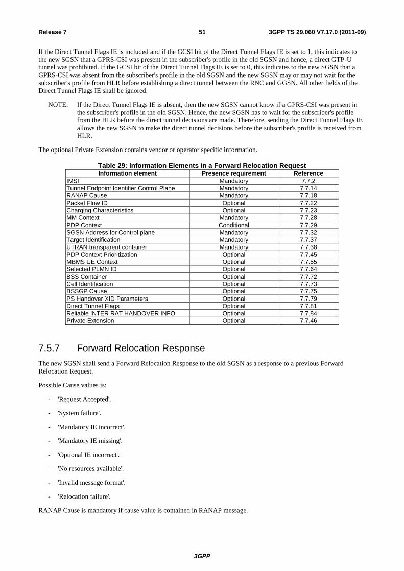
3GPP
3GPP TS 29.060 V7.17.0 (2011-09) 51 Release 7
If the Direct Tunnel Flags IE is included and if the GCSI bit of the Direct Tunnel Flags IE is set to 1, this indicates to
the new SGSN that a GPRS-CSI was present in the subscriber's profile in the old SGSN and hence, a direct GTP-U
tunnel was prohibited. If the GCSI bit of the Direct Tunnel Flags IE is set to 0, this indicates to the new SGSN that a
GPRS-CSI was absent from the subscriber's profile in the old SGSN and the new SGSN may or may not wait for the
subscriber's profile from HLR before establishing a direct tunnel between the RNC and GGSN. All other fields of the
Direct Tunnel Flags IE shall be ignored.
NOTE: If the Direct Tunnel Flags IE is absent, then the new SGSN cannot know if a GPRS-CSI was present in
the subscriber's profile in the old SGSN. Hence, the new SGSN has to wait for the subscriber's profile
from the HLR before the direct tunnel decisions are made. Therefore, sending the Direct Tunnel Flags IE
allows the new SGSN to make the direct tunnel decisions before the subscriber's profile is received from
HLR.
The optional Private Extension contains vendor or operator specific information.
Table 29: Information Elements in a Forward Relocation RequestInformation element Presence requirement Reference
IMSI Mandatory 7.7.2
Tunnel Endpoint Identifier Control Plane Mandatory 7.7.14
RANAP Cause Mandatory 7.7.18
Packet Flow ID Optional 7.7.22
Charging Characteristics Optional 7.7.23
MM Context Mandatory 7.7.28
PDP Context Conditional 7.7.29
SGSN Address for Control plane Mandatory 7.7.32
Target Identification Mandatory 7.7.37
UTRAN transparent container Mandatory 7.7.38
PDP Context Prioritization Optional 7.7.45
MBMS UE Context Optional 7.7.55
Selected PLMN ID Optional 7.7.64
BSS Container Optional 7.7.72
Cell Identification Optional 7.7.73
BSSGP Cause Optional 7.7.75
PS Handover XID Parameters Optional 7.7.79
Direct Tunnel Flags Optional 7.7.81
Reliable INTER RAT HANDOVER INFO Optional 7.7.84
Private Extension Optional 7.7.46
7.5.7 Forward Relocation Response
The new SGSN shall send a Forward Relocation Response to the old SGSN as a response to a previous Forward
Relocation Request.
Possible Cause values is:
- 'Request Accepted'.
- 'System failure'.
- 'Mandatory IE incorrect'.
- 'Mandatory IE missing'.
- 'Optional IE incorrect'.
- 'No resources available'.
- 'Invalid message format'.
- 'Relocation failure'.
RANAP Cause is mandatory if cause value is contained in RANAP message.
3GPP
3GPP TS 29.060 V7.17.0 (2011-09) 52 Release 7
RAB Setup Information, UTRAN transparent container and RANAP Cause are information from the target RNC in the
new SGSN.
One or more RAB Setup Information parameters may be sent in this message. This information element shall be
included if the Cause contains the value 'Request accepted' and there is at least one RAB assigned in the new SGSN.
The new SGSN shall include a SGSN Address for control plane. The old SGSN shall store this SGSN Address and use
it when sending control plane messages for the MS to the new SGSN in the SRNS Relocation Procedure. If the Forward
Relocation Request received from the old SGSN includes an IPv6 SGSN address, an IPv4/IPv6 capable SGSN shall
include an IPv6 address in the field SGSN Address for Control Plane, otherwise, it shall include an IPv4 address in this
field.
The Tunnel Endpoint Identifier Control Plane field specifies a Tunnel Endpoint Identifier that is chosen by the new
SGSN. The old SGSN shall include this Tunnel Endpoint Identifier in the GTP header of all subsequent signalling
messages that are sent from the old SGSN to the new SGSN. This information element shall be included if the Cause
contains the value 'Request accepted'.
One or more Additional RAB Setup Information parameters may be sent in this message for IPv6. This information
element shall be included if the Cause contains the value 'Request accepted' and there is at least one RAB assigned in
the new SGSN.
The new SGSN may include its SGSN number. If the old SGSN receives the SGSN number of the new SGSN it shall
include this number when informing interworking core network nodes that there is a need to re-route previously sent
requests against the new SGSN, e.g. in LCS the GMLC will use this SGSN number to re-activate the Location Request
to the new SGSN (3GPP TS 23.271 [24]).
For PS handover to A/Gb mode, if a cause value is received from the Target BSC, the BSSGP Cause IE shall be
included and shall be set to the cause value received from the target BSC.
If the new SGSN has received the Cell Identification IE in the Forward Relocation Request message and the PS
handover continues for at least one PDP Context, the NSAPI for each of the active PDP Contexts received in the
Forward Relocation Request for which the PS handover continues are indicated in their priority order, highest priority
first. One instance of the NSAPI IE will be inserted for each of these PDP Contexts.
The BSS Container information element contains the radio-related and core network information for the PS handover to
A/Gb mode. For PS handover to Iu mode, the UTRAN transparent container shall be used. This information element
shall be included if the Cause contains the value 'Request accepted' .
The Tunnel Endpoint Identifier Data II IE, one information for each PDP context, contains the tunnel endpoint of the
new SGSN. The SGSN Address for User Traffic contains the IP address of the new SGSN for data forwarding to the
new SGSN during the PS handover procedure. The List of set-up PFCs IE contains the Packet Flow Identifiers of the
PFCs that were successfully allocated in the target system during a PS handover.
The new SGSN receiving a Forward Relocation Request with the optional PS Handover XID Parameters, Packet Flow
ID IE, BSS Container, Cell Identification IEs mandatory UTRAN transparent container, Target identification IEs
having their value part empty according to their minimum defined length and RANAP Cause IEs set to cause #43 shall
not reject this message if it supports the PS handover.
The optional Private Extension contains vendor or operator specific information.
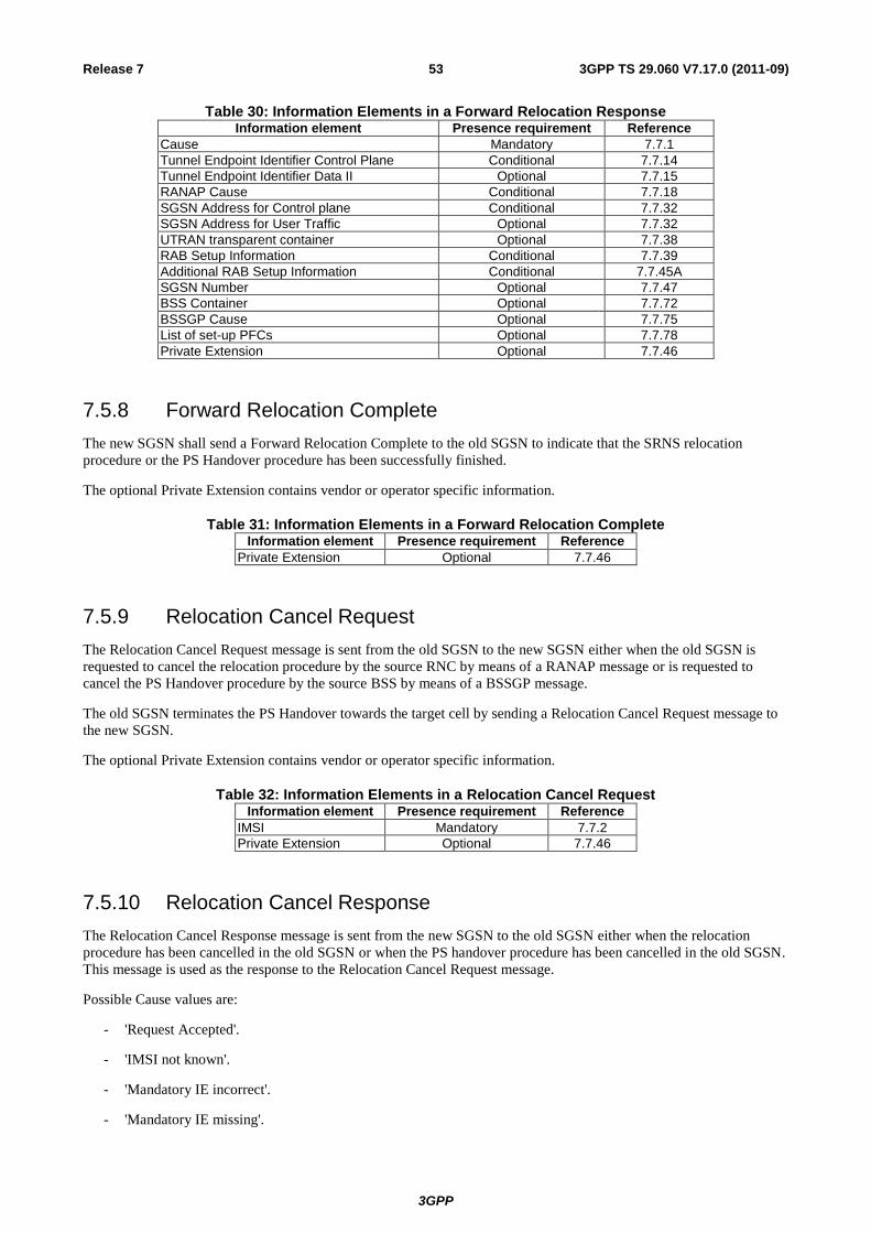
3GPP
3GPP TS 29.060 V7.17.0 (2011-09) 53 Release 7
Table 30: Information Elements in a Forward Relocation ResponseInformation element Presence requirement Reference
Cause Mandatory 7.7.1
Tunnel Endpoint Identifier Control Plane Conditional 7.7.14
Tunnel Endpoint Identifier Data II Optional 7.7.15
RANAP Cause Conditional 7.7.18
SGSN Address for Control plane Conditional 7.7.32
SGSN Address for User Traffic Optional 7.7.32
UTRAN transparent container Optional 7.7.38
RAB Setup Information Conditional 7.7.39
Additional RAB Setup Information Conditional 7.7.45A
SGSN Number Optional 7.7.47
BSS Container Optional 7.7.72
BSSGP Cause Optional 7.7.75
List of set-up PFCs Optional 7.7.78
Private Extension Optional 7.7.46
7.5.8 Forward Relocation Complete
The new SGSN shall send a Forward Relocation Complete to the old SGSN to indicate that the SRNS relocation
procedure or the PS Handover procedure has been successfully finished.
The optional Private Extension contains vendor or operator specific information.
Table 31: Information Elements in a Forward Relocation CompleteInformation element Presence requirement Reference
Private Extension Optional 7.7.46
7.5.9 Relocation Cancel Request
The Relocation Cancel Request message is sent from the old SGSN to the new SGSN either when the old SGSN is
requested to cancel the relocation procedure by the source RNC by means of a RANAP message or is requested to
cancel the PS Handover procedure by the source BSS by means of a BSSGP message.
The old SGSN terminates the PS Handover towards the target cell by sending a Relocation Cancel Request message to
the new SGSN.
The optional Private Extension contains vendor or operator specific information.
Table 32: Information Elements in a Relocation Cancel RequestInformation element Presence requirement Reference
IMSI Mandatory 7.7.2
Private Extension Optional 7.7.46
7.5.10 Relocation Cancel Response
The Relocation Cancel Response message is sent from the new SGSN to the old SGSN either when the relocation
procedure has been cancelled in the old SGSN or when the PS handover procedure has been cancelled in the old SGSN.
This message is used as the response to the Relocation Cancel Request message.
Possible Cause values are:
- 'Request Accepted'.
- 'IMSI not known'.
- 'Mandatory IE incorrect'.
- 'Mandatory IE missing'.
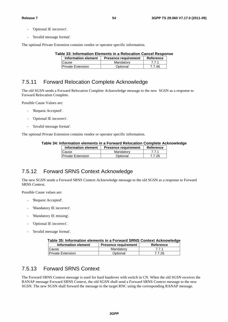
3GPP
3GPP TS 29.060 V7.17.0 (2011-09) 54 Release 7
- 'Optional IE incorrect'.
- 'Invalid message format'.
The optional Private Extension contains vendor or operator specific information.
Table 33: Information Elements in a Relocation Cancel ResponseInformation element Presence requirement Reference
Cause Mandatory 7.7.1
Private Extension Optional 7.7.46
7.5.11 Forward Relocation Complete Acknowledge
The old SGSN sends a Forward Relocation Complete Acknowledge message to the new SGSN as a response to
Forward Relocation Complete.
Possible Cause Values are:
- 'Request Accepted'.
- 'Optional IE incorrect'.
- 'Invalid message format'.
The optional Private Extension contains vendor or operator specific information.
Table 34: Information elements in a Forward Relocation Complete AcknowledgeInformation element Presence requirement Reference
Cause Mandatory 7.7.1
Private Extension Optional 7.7.26
7.5.12 Forward SRNS Context Acknowledge
The new SGSN sends a Forward SRNS Context Acknowledge message to the old SGSN as a response to Forward
SRNS Context.
Possible Cause values are:
- 'Request Accepted'.
- 'Mandatory IE incorrect'.
- 'Mandatory IE missing'.
- 'Optional IE incorrect'.
- 'Invalid message format'.
Table 35: Information elements in a Forward SRNS Context AcknowledgeInformation element Presence requirement Reference
Cause Mandatory 7.7.1
Private Extension Optional 7.7.26
7.5.13 Forward SRNS Context
The Forward SRNS Context message is used for hard handover with switch in CN. When the old SGSN receives the
RANAP message Forward SRNS Context, the old SGSN shall send a Forward SRNS Context message to the new
SGSN. The new SGSN shall forward the message to the target RNC using the corresponding RANAP message.
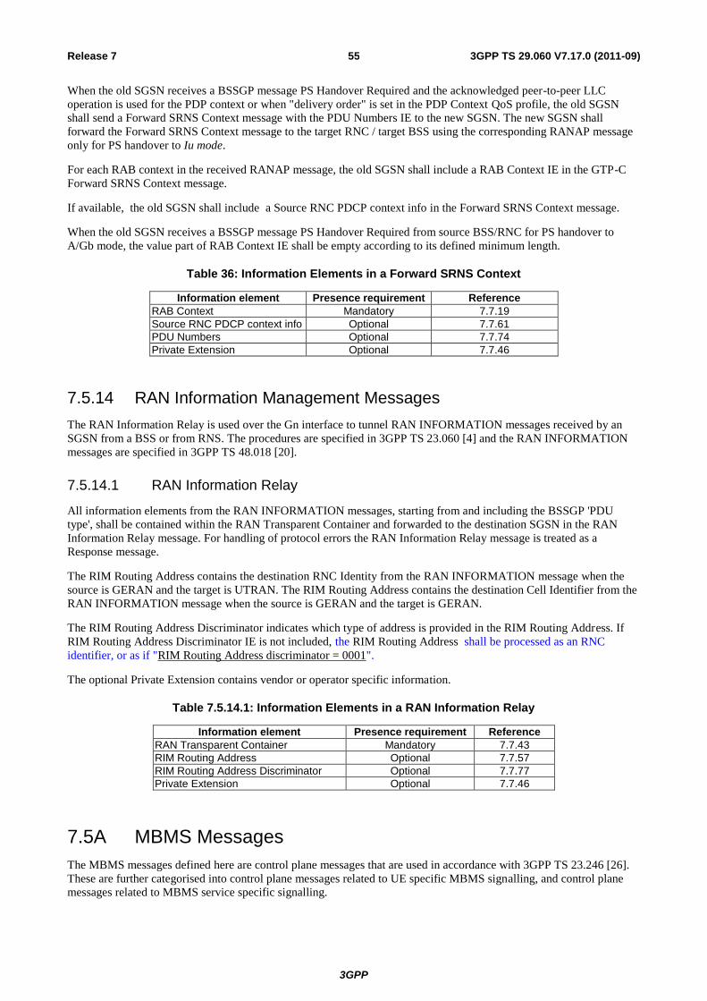
3GPP
3GPP TS 29.060 V7.17.0 (2011-09) 55 Release 7
When the old SGSN receives a BSSGP message PS Handover Required and the acknowledged peer-to-peer LLC
operation is used for the PDP context or when "delivery order" is set in the PDP Context QoS profile, the old SGSN
shall send a Forward SRNS Context message with the PDU Numbers IE to the new SGSN. The new SGSN shall
forward the Forward SRNS Context message to the target RNC / target BSS using the corresponding RANAP message
only for PS handover to Iu mode.
For each RAB context in the received RANAP message, the old SGSN shall include a RAB Context IE in the GTP-C
Forward SRNS Context message.
If available, the old SGSN shall include a Source RNC PDCP context info in the Forward SRNS Context message.
When the old SGSN receives a BSSGP message PS Handover Required from source BSS/RNC for PS handover to
A/Gb mode, the value part of RAB Context IE shall be empty according to its defined minimum length.
Table 36: Information Elements in a Forward SRNS Context
Information element Presence requirement Reference
RAB Context Mandatory 7.7.19
Source RNC PDCP context info Optional 7.7.61
PDU Numbers Optional 7.7.74
Private Extension Optional 7.7.46
7.5.14 RAN Information Management Messages
The RAN Information Relay is used over the Gn interface to tunnel RAN INFORMATION messages received by an
SGSN from a BSS or from RNS. The procedures are specified in 3GPP TS 23.060 [4] and the RAN INFORMATION
messages are specified in 3GPP TS 48.018 [20].
7.5.14.1 RAN Information Relay
All information elements from the RAN INFORMATION messages, starting from and including the BSSGP 'PDU
type', shall be contained within the RAN Transparent Container and forwarded to the destination SGSN in the RAN
Information Relay message. For handling of protocol errors the RAN Information Relay message is treated as a
Response message.
The RIM Routing Address contains the destination RNC Identity from the RAN INFORMATION message when the
source is GERAN and the target is UTRAN. The RIM Routing Address contains the destination Cell Identifier from the
RAN INFORMATION message when the source is GERAN and the target is GERAN.
The RIM Routing Address Discriminator indicates which type of address is provided in the RIM Routing Address. If
RIM Routing Address Discriminator IE is not included, the RIM Routing Address shall be processed as an RNC
identifier, or as if "RIM Routing Address discriminator = 0001".
The optional Private Extension contains vendor or operator specific information.
Table 7.5.14.1: Information Elements in a RAN Information Relay
Information element Presence requirement Reference
RAN Transparent Container Mandatory 7.7.43
RIM Routing Address Optional 7.7.57
RIM Routing Address Discriminator Optional 7.7.77
Private Extension Optional 7.7.46
7.5A MBMS Messages
The MBMS messages defined here are control plane messages that are used in accordance with 3GPP TS 23.246 [26].
These are further categorised into control plane messages related to UE specific MBMS signalling, and control plane
messages related to MBMS service specific signalling.
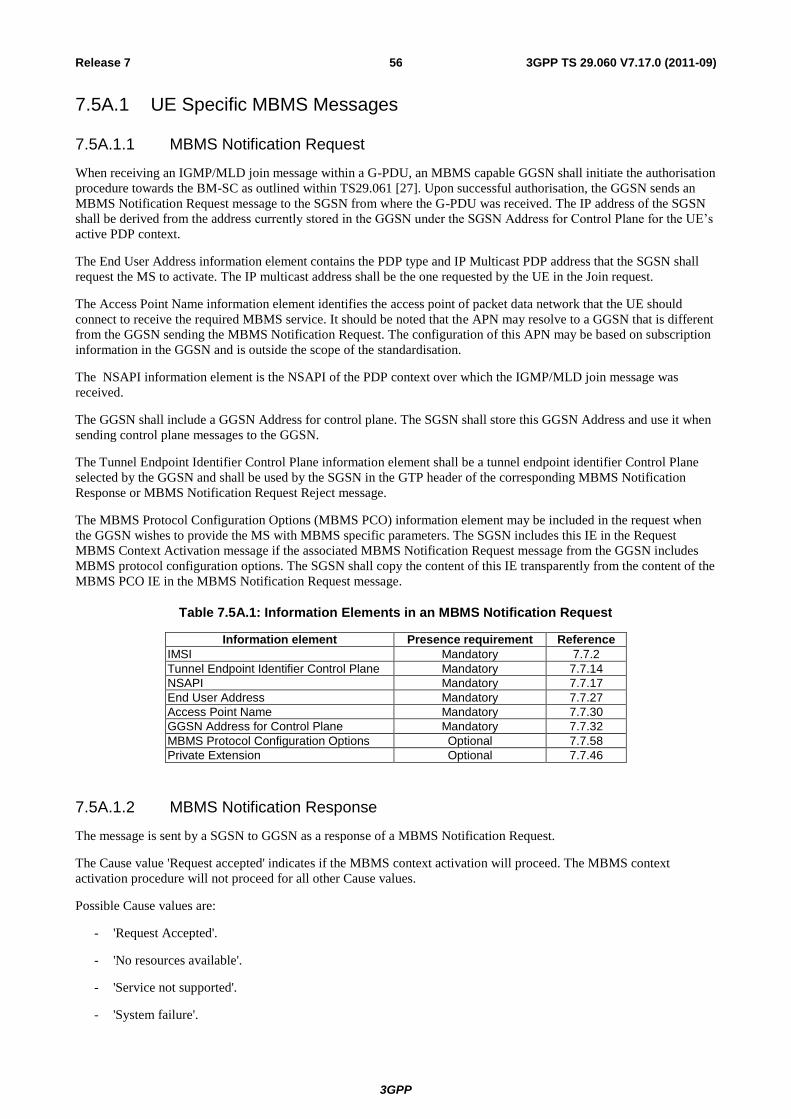
3GPP
3GPP TS 29.060 V7.17.0 (2011-09) 56 Release 7
7.5A.1 UE Specific MBMS Messages
7.5A.1.1 MBMS Notification Request
When receiving an IGMP/MLD join message within a G-PDU, an MBMS capable GGSN shall initiate the authorisation
procedure towards the BM-SC as outlined within TS29.061 [27]. Upon successful authorisation, the GGSN sends an
MBMS Notification Request message to the SGSN from where the G-PDU was received. The IP address of the SGSN
shall be derived from the address currently stored in the GGSN under the SGSN Address for Control Plane for the UE’s
active PDP context.
The End User Address information element contains the PDP type and IP Multicast PDP address that the SGSN shall
request the MS to activate. The IP multicast address shall be the one requested by the UE in the Join request.
The Access Point Name information element identifies the access point of packet data network that the UE should
connect to receive the required MBMS service. It should be noted that the APN may resolve to a GGSN that is different
from the GGSN sending the MBMS Notification Request. The configuration of this APN may be based on subscription
information in the GGSN and is outside the scope of the standardisation.
The NSAPI information element is the NSAPI of the PDP context over which the IGMP/MLD join message was
received.
The GGSN shall include a GGSN Address for control plane. The SGSN shall store this GGSN Address and use it when
sending control plane messages to the GGSN.
The Tunnel Endpoint Identifier Control Plane information element shall be a tunnel endpoint identifier Control Plane
selected by the GGSN and shall be used by the SGSN in the GTP header of the corresponding MBMS Notification
Response or MBMS Notification Request Reject message.
The MBMS Protocol Configuration Options (MBMS PCO) information element may be included in the request when
the GGSN wishes to provide the MS with MBMS specific parameters. The SGSN includes this IE in the Request
MBMS Context Activation message if the associated MBMS Notification Request message from the GGSN includes
MBMS protocol configuration options. The SGSN shall copy the content of this IE transparently from the content of the
MBMS PCO IE in the MBMS Notification Request message.
Table 7.5A.1: Information Elements in an MBMS Notification Request
Information element Presence requirement Reference
IMSI Mandatory 7.7.2
Tunnel Endpoint Identifier Control Plane Mandatory 7.7.14
NSAPI Mandatory 7.7.17
End User Address Mandatory 7.7.27
Access Point Name Mandatory 7.7.30
GGSN Address for Control Plane Mandatory 7.7.32
MBMS Protocol Configuration Options Optional 7.7.58
Private Extension Optional 7.7.46
7.5A.1.2 MBMS Notification Response
The message is sent by a SGSN to GGSN as a response of a MBMS Notification Request.
The Cause value 'Request accepted' indicates if the MBMS context activation will proceed. The MBMS context
activation procedure will not proceed for all other Cause values.
Possible Cause values are:
- 'Request Accepted'.
- 'No resources available'.
- 'Service not supported'.
- 'System failure'.
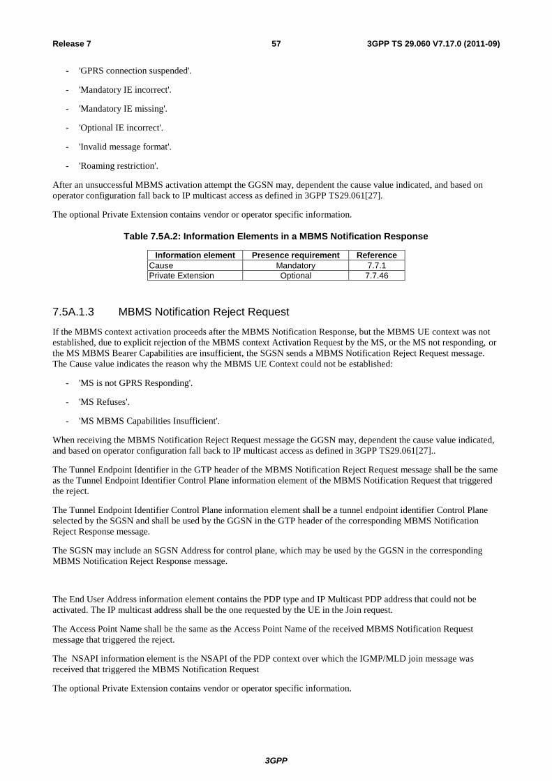
3GPP
3GPP TS 29.060 V7.17.0 (2011-09) 57 Release 7
- 'GPRS connection suspended'.
- 'Mandatory IE incorrect'.
- 'Mandatory IE missing'.
- 'Optional IE incorrect'.
- 'Invalid message format'.
- 'Roaming restriction'.
After an unsuccessful MBMS activation attempt the GGSN may, dependent the cause value indicated, and based on
operator configuration fall back to IP multicast access as defined in 3GPP TS29.061[27].
The optional Private Extension contains vendor or operator specific information.
Table 7.5A.2: Information Elements in a MBMS Notification Response
Information element Presence requirement Reference
Cause Mandatory 7.7.1
Private Extension Optional 7.7.46
7.5A.1.3 MBMS Notification Reject Request
If the MBMS context activation proceeds after the MBMS Notification Response, but the MBMS UE context was not
established, due to explicit rejection of the MBMS context Activation Request by the MS, or the MS not responding, or
the MS MBMS Bearer Capabilities are insufficient, the SGSN sends a MBMS Notification Reject Request message.
The Cause value indicates the reason why the MBMS UE Context could not be established:
- 'MS is not GPRS Responding'.
- 'MS Refuses'.
- 'MS MBMS Capabilities Insufficient'.
When receiving the MBMS Notification Reject Request message the GGSN may, dependent the cause value indicated,
and based on operator configuration fall back to IP multicast access as defined in 3GPP TS29.061[27]..
The Tunnel Endpoint Identifier in the GTP header of the MBMS Notification Reject Request message shall be the same
as the Tunnel Endpoint Identifier Control Plane information element of the MBMS Notification Request that triggered
the reject.
The Tunnel Endpoint Identifier Control Plane information element shall be a tunnel endpoint identifier Control Plane
selected by the SGSN and shall be used by the GGSN in the GTP header of the corresponding MBMS Notification
Reject Response message.
The SGSN may include an SGSN Address for control plane, which may be used by the GGSN in the corresponding
MBMS Notification Reject Response message.
The End User Address information element contains the PDP type and IP Multicast PDP address that could not be
activated. The IP multicast address shall be the one requested by the UE in the Join request.
The Access Point Name shall be the same as the Access Point Name of the received MBMS Notification Request
message that triggered the reject.
The NSAPI information element is the NSAPI of the PDP context over which the IGMP/MLD join message was
received that triggered the MBMS Notification Request
The optional Private Extension contains vendor or operator specific information.
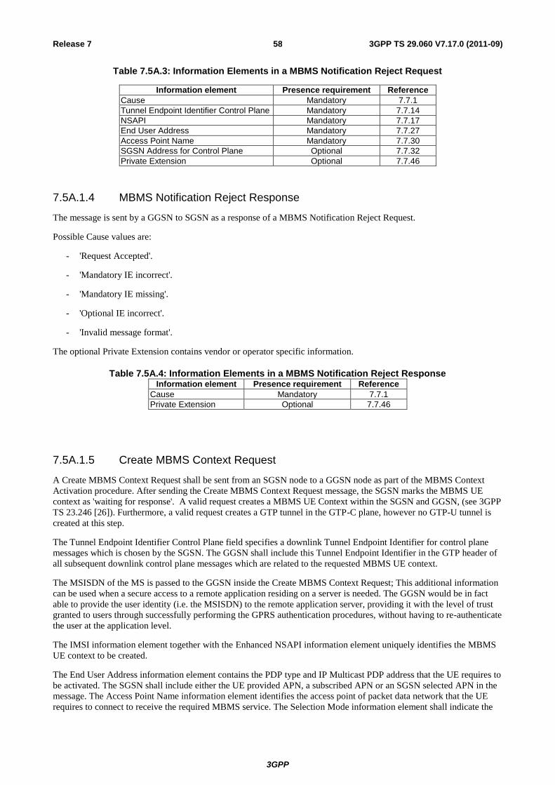
3GPP
3GPP TS 29.060 V7.17.0 (2011-09) 58 Release 7
Table 7.5A.3: Information Elements in a MBMS Notification Reject Request
Information element Presence requirement Reference
Cause Mandatory 7.7.1
Tunnel Endpoint Identifier Control Plane Mandatory 7.7.14
NSAPI Mandatory 7.7.17
End User Address Mandatory 7.7.27
Access Point Name Mandatory 7.7.30
SGSN Address for Control Plane Optional 7.7.32
Private Extension Optional 7.7.46
7.5A.1.4 MBMS Notification Reject Response
The message is sent by a GGSN to SGSN as a response of a MBMS Notification Reject Request.
Possible Cause values are:
- 'Request Accepted'.
- 'Mandatory IE incorrect'.
- 'Mandatory IE missing'.
- 'Optional IE incorrect'.
- 'Invalid message format'.
The optional Private Extension contains vendor or operator specific information.
Table 7.5A.4: Information Elements in a MBMS Notification Reject ResponseInformation element Presence requirement Reference
Cause Mandatory 7.7.1
Private Extension Optional 7.7.46
7.5A.1.5 Create MBMS Context Request
A Create MBMS Context Request shall be sent from an SGSN node to a GGSN node as part of the MBMS Context
Activation procedure. After sending the Create MBMS Context Request message, the SGSN marks the MBMS UE
context as 'waiting for response'. A valid request creates a MBMS UE Context within the SGSN and GGSN, (see 3GPP
TS 23.246 [26]). Furthermore, a valid request creates a GTP tunnel in the GTP-C plane, however no GTP-U tunnel is
created at this step.
The Tunnel Endpoint Identifier Control Plane field specifies a downlink Tunnel Endpoint Identifier for control plane
messages which is chosen by the SGSN. The GGSN shall include this Tunnel Endpoint Identifier in the GTP header of
all subsequent downlink control plane messages which are related to the requested MBMS UE context.
The MSISDN of the MS is passed to the GGSN inside the Create MBMS Context Request; This additional information
can be used when a secure access to a remote application residing on a server is needed. The GGSN would be in fact
able to provide the user identity (i.e. the MSISDN) to the remote application server, providing it with the level of trust
granted to users through successfully performing the GPRS authentication procedures, without having to re-authenticate
the user at the application level.
The IMSI information element together with the Enhanced NSAPI information element uniquely identifies the MBMS
UE context to be created.
The End User Address information element contains the PDP type and IP Multicast PDP address that the UE requires to
be activated. The SGSN shall include either the UE provided APN, a subscribed APN or an SGSN selected APN in the
message. The Access Point Name information element identifies the access point of packet data network that the UE
requires to connect to receive the required MBMS service. The Selection Mode information element shall indicate the
3GPP
3GPP TS 29.060 V7.17.0 (2011-09) 59 Release 7
origin of the APN in the message. The APN and End User Address information element shall uniquely identify the
MBMS service.
The SGSN shall include an SGSN Address for control plane, which may differ from that provided by the underlying
network service (e.g. IP). If the GGSN is IPv6 capable, the IPv4/IPv6 capable SGSN shall include IPv6 addresses in the
field SGSN Address for signalling. Otherwise, it shall include IPv4 addresses in this field. The GGSN shall store the
SGSN Address and use them when sending control plane on this GTP tunnel for the UE.
The SGSN shall include a Recovery information element into the Create MBMS Context Request if the SGSN is in
contact with the GGSN for the very first time or if the SGSN has restarted recently and the new Restart Counter value
has not yet been indicated to the GGSN. The GGSN that receives a Recovery information element in the Create MBMS
Context Request message element shall handle it in the same way as when receiving an Echo Response message. The
Create MBMS Context Request message shall be considered as a valid activation request for the MBMS UE context
included in the message.
The SGSN shall include Trace Reference, Trace Type, Trigger Id, OMC Identity and Additional Trace Info in the
message if GGSN trace is activated in the GGSN. The SGSN shall copy Trace Reference, Trace Type, and OMC
Identity from the trace request received from the HLR or OMC and the Trace Activity Control shall be set to Trace
Activation.
If BM-SC trace is to be activated in the BM-SC (via the GGSN), the SGSN shall include Additional BM-SC Trace Info
in the message. The SGSN shall populate the Additional MBMS Trace Info IE with the values of the relevant
parameters included in the trace request received from the HLR or OMC, and the Trace Activity Control For BM-SC
value shall be set to Trace Activation.
If Additional Trace Info and Additional MBMS Trace Info are both included within the message, the values of Trace
Reference2 and Trace Recording Session Reference shall be the same in each IE.
For more detailed description of Trace Session activation/deactivation procedures see 3GPP TS 32.422 [31]
For SGSN and GGSN trace record description see 3GPP TS 32.423 [32]
The SGSN shall include the Routeing Area Identity (RAI) of the SGSN where the UE is registered. The MCC and
MNC components shall be populated with the MCC and MNC, respectively, of the SGSN where the UE is registered.
The LAC and RAC components shall be populated by the SGSN with the LAC and RAC, respectively, of where the
UE is located at the time of the MBMS Context invocation.
The SGSN shall include the User Location Information IE, MS Time Zone IE, RAT Type IE and the IMEI(SV) IE if
they are available (see sub-clause 15.1.1a of 3GPP TS 23.060 [4] for more information). If the User Location
Information IE is included then the SGSN shall include the CGI or SAI in the 'Geographic Location' field depending on
whether the MS is in a cell or a service area respectively.

3GPP
3GPP TS 29.060 V7.17.0 (2011-09) 60 Release 7
The optional Private Extension contains vendor or operator specific information.
The MBMS Protocol Configuration Options (MBMS PCO) information element may be included in the request when
the MS provides the GGSN with MBMS specific parameters. The SGSN includes this IE in the Create MBMS Context
Request if the associated Activate MBMS Context Request from the MS includes MBMS protocol configuration
options. The SGSN shall copy the content of this IE transparently from the content of the MBMS PCO IE in the
Activate MBMS Context Request message.
Table 7.5A.5: Information Elements in a Create MBMS Context Request
Information element Presence requirement Reference
IMSI Conditional 7.7.2
Routeing Area Identity (RAI) Mandatory 7.7.3
Recovery Optional 7.7.11
Selection mode Conditional 7.7.12
Tunnel Endpoint Identifier Control Plane Conditional 7.7.14
Trace Reference Optional 7.7.24
Trace Type Optional 7.7.25
End User Address Mandatory 7.7.27
Access Point Name Mandatory 7.7.30
SGSN Address for signalling Mandatory GSN Address 7.7.32
MSISDN Conditional 7.7.33
Trigger Id Optional 7.7.41
OMC Identity Optional 7.7.42
RAT Type Optional 7.7.50
User Location Information Optional 7.7.51
MS Time Zone Optional 7.7.52
IMEI(SV) Optional 7.7.53
MBMS Protocol Configuration Options Optional 7.7.58
Additonal Trace Info Optional 7.7.62
Enhanced NSAPI Mandatory 7.7.67
Additional MBMS Trace Info Optional 7.7.68
Private Extension Optional 7.7.46
7.5A.1.6 Create MBMS Context Response
The message shall be sent from a GGSN node to a SGSN node as a response of a Create MBMS Context Request.
When the SGSN receives a Create MBMS Context Response with the Cause value indicating 'Request Accepted', the
SGSN may be required to register with the GGSN. For further details see MBMS Registration Request procedure.
The Cause value indicates if a MBMS UE context has been created in the GGSN or not. An MBMS UE context has not
been created in the GGSN if the Cause differs from 'Request accepted'. Possible Cause values are:
- "Request Accepted".
- "No resources available".
- "No memory is available".
- "Missing or unknown APN".
- "Unknown PDP address or PDP type".
- "User authentication failed".
- "System failure".
- "Mandatory IE incorrect".
- "Mandatory IE missing".
- "Optional IE incorrect".
- "Invalid message format".

3GPP
3GPP TS 29.060 V7.17.0 (2011-09) 61 Release 7
- "APN access denied – no subscription".
'No resources available' indicates that not enough resources are available within the network to allow the MBMS UE
Context to be created. 'Missing or unknown APN' indicates e.g. when the GGSN does not support the Access Point
Name. 'Unknown PDP address or PDP type' indicates when the GGSN does not support the PDP type or the PDP
address. Within the scope of MBMS message, an unknown PDP address is considered to be unknown mulitcast address
/ service.
'User authentication failed' indicates that the external packet network has rejected the service requested by the user.
Only the Cause information element shall be included in the response if the Cause contains another value than 'Request
accepted'.
All information elements, except Recovery, Charging Gateway Address, Tunnel Endpoint Identifier Control Plane and
Private Extension, are mandatory if the Cause contains the value 'Request accepted'.
The Tunnel Endpoint Identifier Control Plane field specifies an uplink Tunnel Endpoint Identifier for control plane
messages, which is chosen by the GGSN. The SGSN shall include this Tunnel Endpoint Identifier in the GTP header of
all subsequent uplink-control plane messages, which are related to the requested MBMS UE context.
The GGSN shall include a GGSN Address for control plane, which may differ from that provided by the underlying
network service (e.g. IP).
If the Create MBMS Context Request received from the SGSN included IPv6 SGSN address, an IPv4/IPv6 capable
GGSN shall include IPv6 addresses in the fields GGSN Address for Control Plane, and IPv4 addresses in the fields
Alternative GGSN Address for Control Plane. If SGSN included only an IPv4 SGSN address in the request, IPv4/IPv6
capable GGSN shall include IPv4 addresses in the fields GGSN Address for Control Plane and IPv6 addresses in the
fields Alternative GGSN Address for Control Plane. The SGSN shall store these GGSN Addresses and use one set of
them when sending control plane on this GTP tunnel.
The GGSN shall include the Recovery information element into the Create MBMS Context Response if the GGSN is in
contact with the SGSN for the first time or the GGSN has restarted recently and the new Restart Counter value has not
yet been indicated to the SGSN. The SGSN receiving the Recovery information element shall handle it as when an
Echo Response message is received but shall consider the MBMS UE context being created as active if the response
indicates successful context activation at the GGSN.
The Charging ID is used to identify all charging records produced in SGSN(s) and the GGSN for this MBMS UE
context. The Charging ID is generated by the GGSN and shall be unique within the GGSN.
The Charging Gateway Address is the IP address of the recommended Charging Gateway Functionality to which the
SGSN should transfer the Charging Detail Records (CDR) for this MBMS UE Context.
The Alternative Charging Gateway Address IE has a similar purpose as the Charging Gateway Address but enables co-
existence of IPv4 and IPv6 stacks in the Ga charging interfaces, without mandating any node to have a dual stack. The
format of the optional Alternative Charging Gateway Address information element is the same as the format of the
Charging Gateway Address.
When both these addresses are present, the Charging Gateway address IE shall contain the IPv4 address of the Charging
Gateway Function and the Alternative Charging Gateway address IE shall contain the IPv6 address of the Charging
Gateway Function.
NOTE: The Charging Gateway Address and Alternative Charging Gateway Address both refer to the same
Charging Gateway Function.
The optional Private Extension contains vendor or operator specific information.
The MBMS Protocol Configuration Options (MBMS PCO) information element may be included in the response when
the GGSN provides the MS with MBMS specific parameters. The SGSN includes this IE in the Activate MBMS
Context Accept message if the associated Create MBMS Context Response message from the GGSN includes MBMS
protocol configuration options. The SGSN shall copy the content of this IE transparently from the content of the MBMS
PCO IE in the Create MBMS Context Response message.
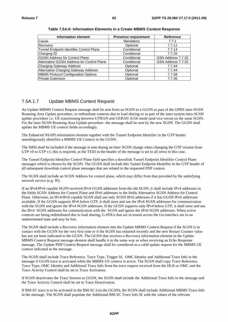
3GPP
3GPP TS 29.060 V7.17.0 (2011-09) 62 Release 7
Table 7.5A.6: Information Elements in a Create MBMS Context Response
Information element Presence requirement Reference
Cause Mandatory 7.7.1
Recovery Optional 7.7.11
Tunnel Endpoint Identifier Control Plane Conditional 7.7.14
Charging ID Conditional 7.7.26
GGSN Address for Control Plane Conditional GSN Address 7.7.32
Alternative GGSN Address for Control Plane Conditional GSN Address 7.7.32
Charging Gateway Address Optional 7.7.44
Alternative Charging Gateway Address Optional 7.7.44
MBMS Protocol Configuration Options Optional 7.7.58
Private Extension Optional 7.7.46
7.5A.1.7 Update MBMS Context Request
An Update MBMS Context Request message shall be sent from an SGSN to a GGSN as part of the GPRS inter-SGSN
Routeing Area Update procedure, to redistribute contexts due to load sharing or as part of the inter-system intra-SGSN
update procedure i.e. UE transitioning between UTRAN and GERAN A/Gb mode (and vice versa) on the same SGSN.
For the inter-SGSN Routeing Area Update procedure -the message shall be sent by the new SGSN. The GGSN shall
update the MBMS UE context fields accordingly.
The Enhanced NSAPI information element together with the Tunnel Endpoint Identifier in the GTP header
unambiguously identifies a MBMS UE Context in the GGSN.
The IMSI shall be included if the message is sent during an Inter SGSN change when changing the GTP version from
GTP v0 to GTP v1; this is required, as the TEID in the header of the message is set to all zeros in this case.
The Tunnel Endpoint Identifier Control Plane field specifies a downlink Tunnel Endpoint Identifier Control Plane
messages which is chosen by the SGSN. The GGSN shall include this Tunnel Endpoint Identifier in the GTP header of
all subsequent downlink control plane messages that are related to the requested PDP context.
The SGSN shall include an SGSN Address for control plane, which may differ from that provided by the underlying
network service (e.g. IP).
If an IPv4/IPv6 capable SGSN received IPv4 GGSN addresses from the old SGSN, it shall include IPv4 addresses in
the fields SGSN Address for Control Plane and IPv6 addresses in the fields Alternative SGSN Address for Control
Plane. Otherwise, an IPv4/IPv6 capable SGSN shall use only SGSN IPv6 addresses if it has GGSN IPv6 addresses
available. If the GGSN supports IPv6 below GTP, it shall store and use the IPv6 SGSN addresses for communication
with the SGSN and ignore the IPv4 SGSN addresses. If the GGSN supports only IPv4 below GTP, it shall store and use
the IPv4 SGSN addresses for communication with the SGSN and ignore the IPv6 SGSN addresses. When active
contexts are being redistributed due to load sharing, G-PDUs that are in transit across the Gn-interface are in an
undetermined state and may be lost.
The SGSN shall include a Recovery information element into the Update MBMS Context Request if the SGSN is in
contact with the GGSN for the very first time or if the SGSN has restarted recently and the new Restart Counter value
has not yet been indicated to the GGSN. The GGSN that receives a Recovery information element in the Update
MBMS Context Request message element shall handle it in the same way as when receiving an Echo Response
message. The Update PDP Context Request message shall be considered as a valid update request for the MBMS UE
context indicated in the message.
The SGSN shall include Trace Reference, Trace Type, Trigger Id, OMC Identity and Additional Trace Info in the
message if GGSN trace is activated while the MBMS UE context is active. The SGSN shall copy Trace Reference,
Trace Type, OMC Identity and Additional Trace Info from the trace request received from the HLR or OMC and the
Trace Activity Control shall be set to Trace Activation.
If SGSN deactivates the Trace Session to GGSN, the SGSN shall include the Additional Trace Info in the message and
the Trace Activity Control shall be set to Trace Deactivation.
If BM-SC trace is to be activated in the BM-SC (via the GGSN), the SGSN shall include Additional MBMS Trace Info
in the message. The SGSN shall populate the Additional BM-SC Trace Info IE with the values of the relevant
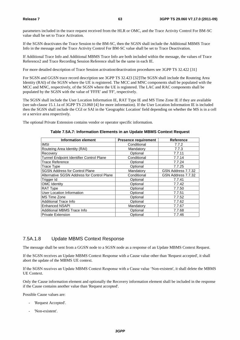
3GPP
3GPP TS 29.060 V7.17.0 (2011-09) 63 Release 7
parameters included in the trace request received from the HLR or OMC, and the Trace Activity Control For BM-SC
value shall be set to Trace Activation.
If the SGSN deactivates the Trace Session to the BM-SC, then the SGSN shall include the Additional MBMS Trace
Info in the message and the Trace Activity Control For BM-SC value shall be set to Trace Deactivation.
If Additional Trace Info and Additional MBMS Trace Info are both included within the message, the values of Trace
Reference2 and Trace Recording Session Reference shall be the same in each IE.
For more detailed description of Trace Session activation/deactivation procedures see 3GPP TS 32.422 [31]
For SGSN and GGSN trace record description see 3GPP TS 32.423 [32]The SGSN shall include the Routeing Area
Identity (RAI) of the SGSN where the UE is registered. The MCC and MNC components shall be populated with the
MCC and MNC, respectively, of the SGSN where the UE is registered. The LAC and RAC components shall be
populated by the SGSN with the value of 'FFFE' and 'FF', respectively.
The SGSN shall include the User Location Information IE, RAT Type IE and MS Time Zone IE if they are available
(see sub-clause 15.1.1a of 3GPP TS 23.060 [4] for more information). If the User Location Information IE is included
then the SGSN shall include the CGI or SAI in the 'Geographic Location' field depending on whether the MS is in a cell
or a service area respectively.
The optional Private Extension contains vendor or operator specific information.
Table 7.5A.7: Information Elements in an Update MBMS Context Request
Information element Presence requirement Reference
IMSI Conditional 7.7.2
Routeing Area Identity (RAI) Mandatory 7.7.3
Recovery Optional 7.7.11
Tunnel Endpoint Identifier Control Plane Conditional 7.7.14
Trace Reference Optional 7.7.24
Trace Type Optional 7.7.25
SGSN Address for Control Plane Mandatory GSN Address 7.7.32
Alternative SGSN Address for Control Plane Conditional GSN Address 7.7.32
Trigger Id Optional 7.7.41
OMC Identity Optional 7.7.42
RAT Type Optional 7.7.50
User Location Information Optional 7.7.51
MS Time Zone Optional 7.7.52
Additional Trace Info Optional 7.7.62
Enhanced NSAPI Mandatory 7.7.67
Additional MBMS Trace Info Optional 7.7.68
Private Extension Optional 7.7.46
7.5A.1.8 Update MBMS Context Response
The message shall be sent from a GGSN node to a SGSN node as a response of an Update MBMS Context Request.
If the SGSN receives an Update MBMS Context Response with a Cause value other than 'Request accepted', it shall
abort the update of the MBMS UE context.
If the SGSN receives an Update MBMS Context Response with a Cause value ‘Non-existent', it shall delete the MBMS
UE Context.
Only the Cause information element and optionally the Recovery information element shall be included in the response
if the Cause contains another value than 'Request accepted'.
Possible Cause values are:
- 'Request Accepted'.
- 'Non-existent'.

3GPP
3GPP TS 29.060 V7.17.0 (2011-09) 64 Release 7
- 'Service not supported'.
- 'System failure'.
- 'Mandatory IE incorrect'.
- 'Mandatory IE missing'.
- 'Optional IE incorrect'.
- 'Invalid message format'.
The Tunnel Endpoint Identifier Control Plane field specifies an uplink Tunnel Endpoint Identifier Control Plane
messages which is chosen by the GGSN. The SGSN shall include this Tunnel Endpoint Identifier in the GTP header of
all subsequent uplink control plane messages which are related to the requested MBMS UE context.
The GGSN shall also include a GGSN address for control plane, which shall not differ from that provided at MBMS UE
context setup time and shall remain unchanged for the lifetime of the MBMS UE context. If the Update MBMS Context
Request received from the SGSN included IPv6 SGSN addresses, an IPv4/IPv6 capable GGSN shall include an IPv6
address in the field GGSN Address for Control Plane and a corresponding IPv4 address in the field Alternative GGSN
Address for Control Plane. If SGSN included only an IPv4 SGSN address in the request, IPv4/IPv6 capable GGSN shall
include IPv4 address for Control plane in the field GGSN Address for Control Plane and IPv6 address for Control plane
in the field Alternative GGSN Address for Control Plane.
The GGSN Address for control plane shall be included if the Cause contains the value 'Request accepted'. The
Alternative GGSN Address shall be included if the GGSN supports IPv6 below GTP and the Cause contains the value
'Request accepted'.
The GGSN shall include the Recovery information element into the Update MBMS Context Response if the GGSN is
in contact with the SGSN for the first time or if the GGSN has restarted recently and the new Restart Counter value has
not yet been indicated to the SGSN. The SGSN receiving the Recovery information element shall handle it as when an
Echo Response message is received but shall consider the MBMS UE context as updated and active if the response
cause indicates a successful operation at the GGSN.
The Charging ID is used to identify all charging records produced in SGSN(s) and the GGSN for this MBMS UE
context. The Charging ID has been previously generated by the GGSN and is unique for this MBMS UE context. If an
inter-SGSN routing area update occurs, it is transferred to the new SGSN as part of each active MBMS UE context.
This information element shall be included if the Cause contains the value 'Request accepted'.
The Charging Gateway Address is the IP address of the recommended Charging Gateway Functionality to which the
SGSN should transfer the Charging Detail Records (CDR) for this MBMS UE Context.
The Alternative Charging Gateway Address IE has a similar purpose as the Charging Gateway Address but enables co-
existence of IPv4 and IPv6 stacks in the Ga charging interfaces, without mandating any node to have a dual stack. The
format of the optional Alternative Charging Gateway Address information element is the same as the format of the
Charging Gateway Address.
When both these addresses are present, the Charging Gateway address IE shall contain the IPv4 address of the Charging
Gateway Function and the Alternative Charging Gateway address IE shall contain the IPv6 address of the Charging
Gateway Function.
NOTE: The Charging Gateway Address and Alternative Charging Gateway Address both refer to the same
Charging Gateway Function.
The optional Private Extension contains vendor or operator specific information.
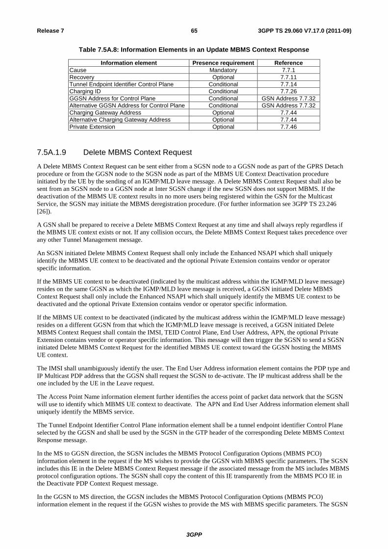
3GPP
3GPP TS 29.060 V7.17.0 (2011-09) 65 Release 7
Table 7.5A.8: Information Elements in an Update MBMS Context Response
Information element Presence requirement Reference
Cause Mandatory 7.7.1
Recovery Optional 7.7.11
Tunnel Endpoint Identifier Control Plane Conditional 7.7.14
Charging ID Conditional 7.7.26
GGSN Address for Control Plane Conditional GSN Address 7.7.32
Alternative GGSN Address for Control Plane Conditional GSN Address 7.7.32
Charging Gateway Address Optional 7.7.44
Alternative Charging Gateway Address Optional 7.7.44
Private Extension Optional 7.7.46
7.5A.1.9 Delete MBMS Context Request
A Delete MBMS Context Request can be sent either from a SGSN node to a GGSN node as part of the GPRS Detach
procedure or from the GGSN node to the SGSN node as part of the MBMS UE Context Deactivation procedure
initiated by the UE by the sending of an IGMP/MLD leave message. A Delete MBMS Context Request shall also be
sent from an SGSN node to a GGSN node at Inter SGSN change if the new SGSN does not support MBMS. If the
deactivation of the MBMS UE context results in no more users being registered within the GSN for the Multicast
Service, the SGSN may initiate the MBMS deregistration procedure. (For further information see 3GPP TS 23.246
[26]).
A GSN shall be prepared to receive a Delete MBMS Context Request at any time and shall always reply regardless if
the MBMS UE context exists or not. If any collision occurs, the Delete MBMS Context Request takes precedence over
any other Tunnel Management message.
An SGSN initiated Delete MBMS Context Request shall only include the Enhanced NSAPI which shall uniquely
identify the MBMS UE context to be deactivated and the optional Private Extension contains vendor or operator
specific information.
If the MBMS UE context to be deactivated (indicated by the multicast address within the IGMP/MLD leave message)
resides on the same GGSN as which the IGMP/MLD leave message is received, a GGSN initiated Delete MBMS
Context Request shall only include the Enhanced NSAPI which shall uniquely identify the MBMS UE context to be
deactivated and the optional Private Extension contains vendor or operator specific information.
If the MBMS UE context to be deactivated (indicated by the multicast address within the IGMP/MLD leave message)
resides on a different GGSN from that which the IGMP/MLD leave message is received, a GGSN initiated Delete
MBMS Context Request shall contain the IMSI, TEID Control Plane, End User Address, APN, the optional Private
Extension contains vendor or operator specific information. This message will then trigger the SGSN to send a SGSN
initiated Delete MBMS Context Request for the identified MBMS UE context toward the GGSN hosting the MBMS
UE context.
The IMSI shall unambiguously identify the user. The End User Address information element contains the PDP type and
IP Multicast PDP address that the GGSN shall request the SGSN to de-activate. The IP multicast address shall be the
one included by the UE in the Leave request.
The Access Point Name information element further identifies the access point of packet data network that the SGSN
will use to identify which MBMS UE context to deactivate. The APN and End User Address information element shall
uniquely identify the MBMS service.
The Tunnel Endpoint Identifier Control Plane information element shall be a tunnel endpoint identifier Control Plane
selected by the GGSN and shall be used by the SGSN in the GTP header of the corresponding Delete MBMS Context
Response message.
In the MS to GGSN direction, the SGSN includes the MBMS Protocol Configuration Options (MBMS PCO)
information element in the request if the MS wishes to provide the GGSN with MBMS specific parameters. The SGSN
includes this IE in the Delete MBMS Context Request message if the associated message from the MS includes MBMS
protocol configuration options. The SGSN shall copy the content of this IE transparently from the MBMS PCO IE in
the Deactivate PDP Context Request message.
In the GGSN to MS direction, the GGSN includes the MBMS Protocol Configuration Options (MBMS PCO)
information element in the request if the GGSN wishes to provide the MS with MBMS specific parameters. The SGSN

3GPP
3GPP TS 29.060 V7.17.0 (2011-09) 66 Release 7
includes this IE in the Deactivate PDP Context Request message if the associated Delete MBMS Context Request
message from the GGSN includes MBMS protocol configuration options. The SGSN shall copy the content of this IE
transparently from the MBMS PCO IE in the Delete MBMS Context Request message.
Table 7.5A.9: Information Elements in a Delete MBMS Context RequestInformation element Presence requirement Reference
IMSI Conditional 7.7.2
Tunnel Endpoint Identifier Control Plane Conditional 7.7.14
End User Address Conditional 7.7.27
Access Point Name Conditional 7.7.30
MBMS Protocol Configuration Options Optional 7.7.58
Enhanced NSAPI Conditional 7.7.67
Private Extension Optional 7.7.46
7.5A.1.10 Delete MBMS Context Response
The message shall be sent as a response to a Delete MBMS Context Request.
A GSN shall ignore a Delete MBMS Context Response for a non-existing MBMS UE context.
If a GSN receives a Delete MBMS Context Request message for a non existing MBMS UE context, it shall send back
to the source of the message a Delete MBMS Context Response message with cause value "Non existent". The TEID
value used in the response message shall be zero.
Possible Cause values are:
- 'Request Accepted'.
- 'Mandatory IE incorrect'.
- 'Mandatory IE missing'.
- 'Optional IE Incorrect'.
- 'Invalid message format'.
- 'Non existent'.
If the received Delete MBMS Context Response contains a cause value other than 'Request accepted' and 'Non
Existent', the PDP context shall be kept active.
The optional Private Extension contains vendor or operator specific information.
In the GGSN to MS direction, the GGSN includes the MBMS Protocol Configuration Options (MBMS PCO)
information element in the response if the GGSN wishes to provide the MS with MBMS specific parameters. The
SGSN includes this IE in the Deactivate PDP Context Accept message if the associated Delete MBMS Context
Response message from the GGSN includes MBMS protocol configuration options. The SGSN shall copy the content
of the IE transparently from the MBMS PCO IE in the Delete MBMS Context Response message.
In the MS to GGSN direction, the SGSN includes the MBMS Protocol Configuration Options (MBMS PCO)
information element in the response if the MS wishes to provide the GGSN with MBMS specific parameters. The
SGSN includes this IE in the Delete MBMS Context Response message if the associated Deactivate PDP Context
Accept message from the MS includes MBMS protocol configuration options. The SGSN shall copy the content of the
IE transparently from the MBMS PCO IE in the Deactivate PDP Context Accept message.
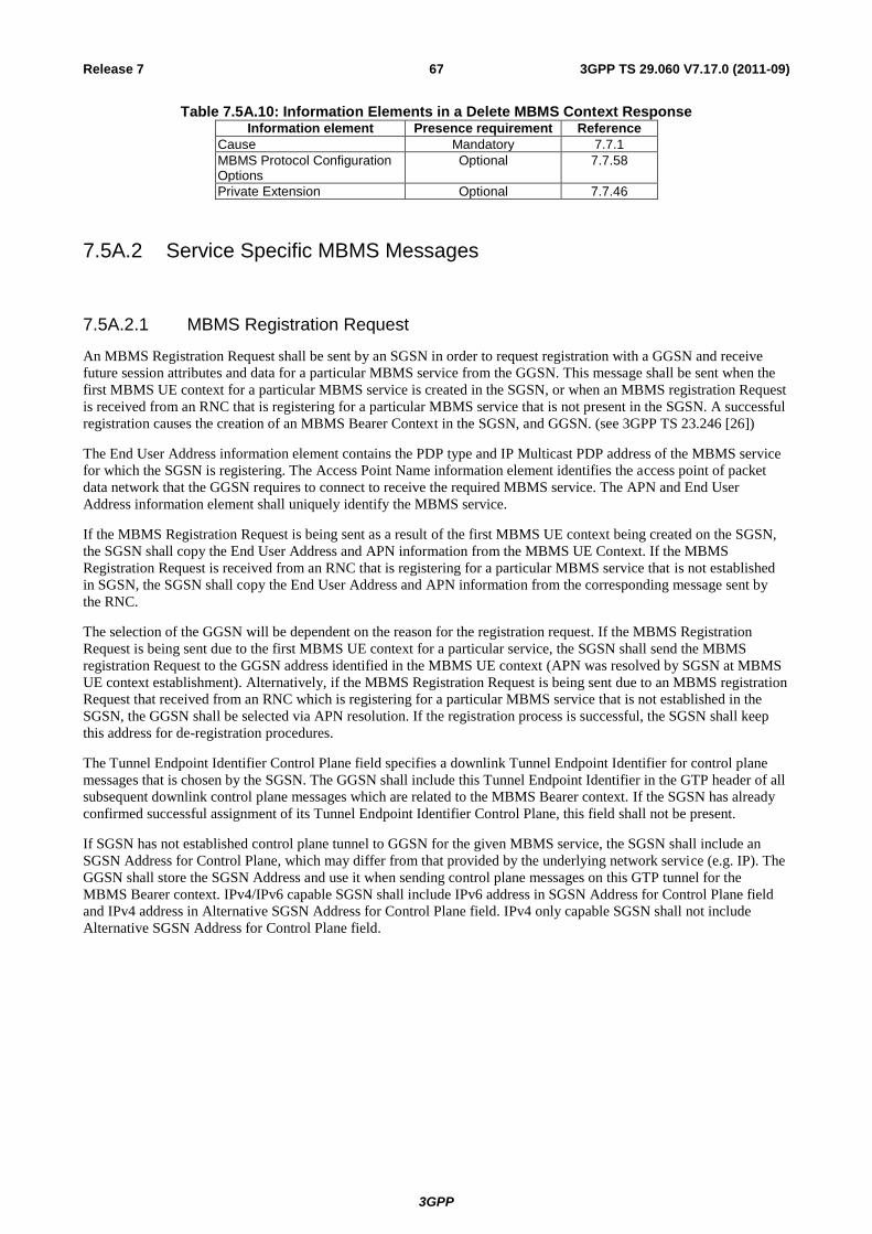
3GPP
3GPP TS 29.060 V7.17.0 (2011-09) 67 Release 7
Table 7.5A.10: Information Elements in a Delete MBMS Context ResponseInformation element Presence requirement Reference
Cause Mandatory 7.7.1
MBMS Protocol Configuration Options
Optional 7.7.58
Private Extension Optional 7.7.46
7.5A.2 Service Specific MBMS Messages
7.5A.2.1 MBMS Registration Request
An MBMS Registration Request shall be sent by an SGSN in order to request registration with a GGSN and receive
future session attributes and data for a particular MBMS service from the GGSN. This message shall be sent when the
first MBMS UE context for a particular MBMS service is created in the SGSN, or when an MBMS registration Request
is received from an RNC that is registering for a particular MBMS service that is not present in the SGSN. A successful
registration causes the creation of an MBMS Bearer Context in the SGSN, and GGSN. (see 3GPP TS 23.246 [26])
The End User Address information element contains the PDP type and IP Multicast PDP address of the MBMS service
for which the SGSN is registering. The Access Point Name information element identifies the access point of packet
data network that the GGSN requires to connect to receive the required MBMS service. The APN and End User
Address information element shall uniquely identify the MBMS service.
If the MBMS Registration Request is being sent as a result of the first MBMS UE context being created on the SGSN,
the SGSN shall copy the End User Address and APN information from the MBMS UE Context. If the MBMS
Registration Request is received from an RNC that is registering for a particular MBMS service that is not established
in SGSN, the SGSN shall copy the End User Address and APN information from the corresponding message sent by
the RNC.
The selection of the GGSN will be dependent on the reason for the registration request. If the MBMS Registration
Request is being sent due to the first MBMS UE context for a particular service, the SGSN shall send the MBMS
registration Request to the GGSN address identified in the MBMS UE context (APN was resolved by SGSN at MBMS
UE context establishment). Alternatively, if the MBMS Registration Request is being sent due to an MBMS registration
Request that received from an RNC which is registering for a particular MBMS service that is not established in the
SGSN, the GGSN shall be selected via APN resolution. If the registration process is successful, the SGSN shall keep
this address for de-registration procedures.
The Tunnel Endpoint Identifier Control Plane field specifies a downlink Tunnel Endpoint Identifier for control plane
messages that is chosen by the SGSN. The GGSN shall include this Tunnel Endpoint Identifier in the GTP header of all
subsequent downlink control plane messages which are related to the MBMS Bearer context. If the SGSN has already
confirmed successful assignment of its Tunnel Endpoint Identifier Control Plane, this field shall not be present.
If SGSN has not established control plane tunnel to GGSN for the given MBMS service, the SGSN shall include an
SGSN Address for Control Plane, which may differ from that provided by the underlying network service (e.g. IP). The
GGSN shall store the SGSN Address and use it when sending control plane messages on this GTP tunnel for the
MBMS Bearer context. IPv4/IPv6 capable SGSN shall include IPv6 address in SGSN Address for Control Plane field
and IPv4 address in Alternative SGSN Address for Control Plane field. IPv4 only capable SGSN shall not include
Alternative SGSN Address for Control Plane field.
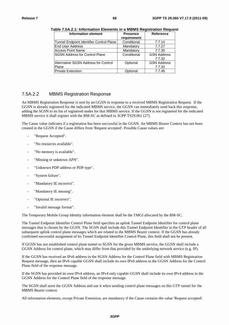
3GPP
3GPP TS 29.060 V7.17.0 (2011-09) 68 Release 7
Table 7.5A.2.1: Information Elements in a MBMS Registration Request Information element Presence
requirement Reference
Tunnel Endpoint Identifier Control Plane Conditional 7.7.14
End User Address Mandatory 7.7.27
Access Point Name Mandatory 7.7.30
SGSN Address for Control Plane Conditional GSN Address 7.7.32
Alternative SGSN Address for Control Plane
Optional GSN Address 7.7.32
Private Extension Optional 7.7.46
7.5A.2.2 MBMS Registration Response
An MBMS Registration Response is sent by an GGSN in response to a received MBMS Registration Request. If the
GGSN is already registered for the indicated MBMS service, the GGSN can immediately send back this response,
adding the SGSN to its list of registered nodes for that MBMS service. If the GGSN is not registered for the indicated
MBMS service it shall register with the BM-SC as defined in 3GPP TS29.061 [27].
The Cause value indicates if a registration has been successful in the GGSN. An MBMS Bearer Context has not been
created in the GGSN if the Cause differs from 'Request accepted'. Possible Cause values are:
- "Request Accepted".
- "No resources available".
- "No memory is available".
- "Missing or unknown APN".
- "Unknown PDP address or PDP type".
- "System failure".
- "Mandatory IE incorrect".
- "Mandatory IE missing".
- "Optional IE incorrect".
- "Invalid message format".
The Temporary Mobile Group Identity information element shall be the TMGI allocated by the BM-SC.
The Tunnel Endpoint Identifier Control Plane field specifies an uplink Tunnel Endpoint Identifier for control plane
messages that is chosen by the GGSN. The SGSN shall include this Tunnel Endpoint Identifier in the GTP header of all
subsequent uplink control plane messages which are related to the MBMS Bearer context. If the GGSN has already
confirmed successful assignment of its Tunnel Endpoint Identifier Control Plane, this field shall not be present.
If GGSN has not established control plane tunnel to SGSN for the given MBMS service, the GGSN shall include a
GGSN Address for control plane, which may differ from that provided by the underlying network service (e.g. IP).
If the GGSN has received an IPv6 address in the SGSN Address for the Control Plane field with MBMS Registration
Request message, then an IPv6 capable GGSN shall include its own IPv6 address in the GGSN Address for the Control
Plane field of the response message.
If the SGSN has provided its own IPv4 address, an IPv4 only capable GGSN shall include its own IPv4 address in the
GGSN Address for the Control Plane field of the response message.
The SGSN shall store the GGSN Address and use it when sending control plane messages on this GTP tunnel for the
MBMS Bearer context.
All information elements, except Private Extension, are mandatory if the Cause contains the value 'Request accepted'.
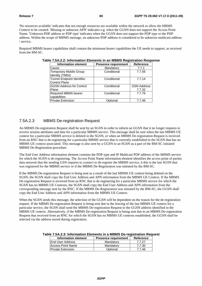
3GPP
3GPP TS 29.060 V7.17.0 (2011-09) 69 Release 7
'No resources available' indicates that not enough resources are available within the network to allow the MBMS
Context to be created. 'Missing or unknown APN' indicates e.g. when the GGSN does not support the Access Point
Name. 'Unknown PDP address or PDP type' indicates when the GGSN does not support the PDP type or the PDP
address. Within the scope of MBMS message, an unknown PDP address is considered to be unknown mulitcast address
/ service.
Required MBMS bearer capabilities shall contain the minimum bearer capabilities the UE needs to support, as received
from the BM-SC.
Table 7.5A.2.2: Information Elements in an MBMS Registration ResponseInformation element Presence requirement Reference
Cause Mandatory 7.7.1
Temporary Mobile Group Identity (TMGI)
Conditional 7.7.56
Tunnel Endpoint Identifier Control Plane
Conditional 7.7.14
GGSN Address for Control Plane
Conditional GSN Address 7.7.32
Required MBMS bearer capabilities
Conditional 7.7.76
Private Extension Optional 7.7.46
7.5A.2.3 MBMS De-registration Request
An MBMS De-registration Request shall be sent by an SGSN in order to inform an GGSN that it no longer requires to
receive session attributes and data for a particular MBMS service. This message shall be sent when the last MBMS UE
context for a particular MBMS service is deleted in the SGSN, or when an MBMS De-registration Request is received
from an RNC that is de-registering for a particular MBMS service that is currently established in the SGSN that has no
MBMS UE context associated. This message is also sent by a GGSN to an SGSN as a part of the BM-SC initiated
MBMS De-Registration procedure.
The End User Address information element contains the PDP type and IP Multicast PDP address of the MBMS service
for which the SGSN is de-registering. The Access Point Name information element identifies the access point of packet
data network that the sending GSN requires to connect to de-register the MBMS service, it this is the last SGSN that
was registered for the MBMS service or if the MBMS De-Registration was initiated by the BM-SC.
If the MBMS De-registration Request is being sent as a result of the last MBMS UE context being deleted on the
SGSN, the SGSN shall copy the End User Address and APN information from the MBMS UE Context. If the MBMS
De-registration Request is received from an RNC that is de-registering for a particular MBMS service for which the
SGSN has no MBMS UE Contexts, the SGSN shall copy the End User Address and APN information from the
corresponding message sent by the RNC. If the MBMS De-Registration was initiated by the BM-SC, the GGSN shall
copy the End User Address and APN information from the MBMS UE Context.
When the SGSN sends this message, the selection of the GGSN will be dependent on the reason for the de-registration
request. If the MBMS De-registration Request is being sent due to the leaving of the last MBMS UE context for a
particular service, the SGSN shall send the MBMS De-registration Request to the GGSN address identified in the
MBMS UE context. Alternatively, if the MBMS De-registration Request is being sent due to an MBMS De-registration
Request that received from an RNC for which the SGSN has no MBMS UE contexts established, the GGSN shall be
selected via the address stored during registration.
Table 7.5A.2.3: Information Elements in a MBMS De-registration Request Information element Presence requirement Reference
End User Address Mandatory 7.7.27
Access Point Name Mandatory 7.7.30
Private Extension Optional 7.7.46
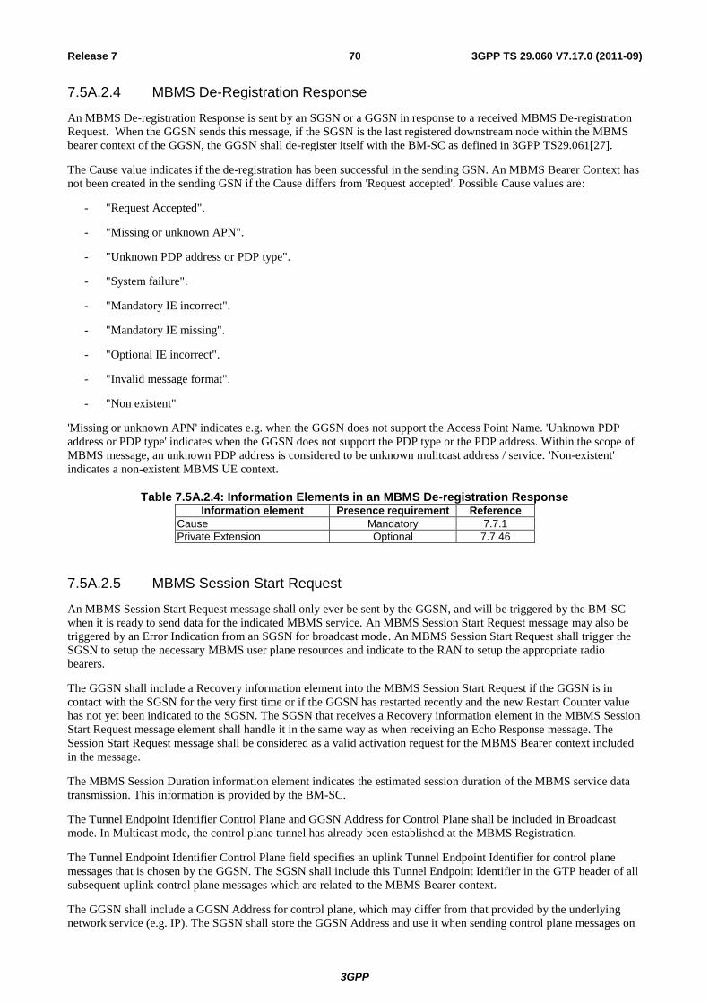
3GPP
3GPP TS 29.060 V7.17.0 (2011-09) 70 Release 7
7.5A.2.4 MBMS De-Registration Response
An MBMS De-registration Response is sent by an SGSN or a GGSN in response to a received MBMS De-registration
Request. When the GGSN sends this message, if the SGSN is the last registered downstream node within the MBMS
bearer context of the GGSN, the GGSN shall de-register itself with the BM-SC as defined in 3GPP TS29.061[27].
The Cause value indicates if the de-registration has been successful in the sending GSN. An MBMS Bearer Context has
not been created in the sending GSN if the Cause differs from 'Request accepted'. Possible Cause values are:
- "Request Accepted".
- "Missing or unknown APN".
- "Unknown PDP address or PDP type".
- "System failure".
- "Mandatory IE incorrect".
- "Mandatory IE missing".
- "Optional IE incorrect".
- "Invalid message format".
- "Non existent"
'Missing or unknown APN' indicates e.g. when the GGSN does not support the Access Point Name. 'Unknown PDP
address or PDP type' indicates when the GGSN does not support the PDP type or the PDP address. Within the scope of
MBMS message, an unknown PDP address is considered to be unknown mulitcast address / service. 'Non-existent'
indicates a non-existent MBMS UE context.
Table 7.5A.2.4: Information Elements in an MBMS De-registration ResponseInformation element Presence requirement Reference
Cause Mandatory 7.7.1
Private Extension Optional 7.7.46
7.5A.2.5 MBMS Session Start Request
An MBMS Session Start Request message shall only ever be sent by the GGSN, and will be triggered by the BM-SC
when it is ready to send data for the indicated MBMS service. An MBMS Session Start Request message may also be
triggered by an Error Indication from an SGSN for broadcast mode. An MBMS Session Start Request shall trigger the
SGSN to setup the necessary MBMS user plane resources and indicate to the RAN to setup the appropriate radio
bearers.
The GGSN shall include a Recovery information element into the MBMS Session Start Request if the GGSN is in
contact with the SGSN for the very first time or if the GGSN has restarted recently and the new Restart Counter value
has not yet been indicated to the SGSN. The SGSN that receives a Recovery information element in the MBMS Session
Start Request message element shall handle it in the same way as when receiving an Echo Response message. The
Session Start Request message shall be considered as a valid activation request for the MBMS Bearer context included
in the message.
The MBMS Session Duration information element indicates the estimated session duration of the MBMS service data
transmission. This information is provided by the BM-SC.
The Tunnel Endpoint Identifier Control Plane and GGSN Address for Control Plane shall be included in Broadcast
mode. In Multicast mode, the control plane tunnel has already been established at the MBMS Registration.
The Tunnel Endpoint Identifier Control Plane field specifies an uplink Tunnel Endpoint Identifier for control plane
messages that is chosen by the GGSN. The SGSN shall include this Tunnel Endpoint Identifier in the GTP header of all
subsequent uplink control plane messages which are related to the MBMS Bearer context.
The GGSN shall include a GGSN Address for control plane, which may differ from that provided by the underlying
network service (e.g. IP). The SGSN shall store the GGSN Address and use it when sending control plane messages on
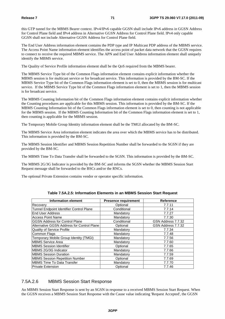
3GPP
3GPP TS 29.060 V7.17.0 (2011-09) 71 Release 7
this GTP tunnel for the MBMS Bearer context. IPv4/IPv6 capable GGSN shall include IPv6 address in GGSN Address
for Control Plane field and IPv4 address in Alternative GGSN Address for Control Plane field. IPv4 only capable
GGSN shall not include Alternative GGSN Address for Control Plane field.
The End User Address information element contains the PDP type and IP Multicast PDP address of the MBMS service.
The Access Point Name information element identifies the access point of packet data network that the GGSN requires
to connect to receive the required MBMS service. The APN and End User Address information element shall uniquely
identify the MBMS service.
The Quality of Service Profile information element shall be the QoS required from the MBMS bearer.
The MBMS Service Type bit of the Common Flags information element contains explicit information whether the
MBMS session is for multicast service or for broadcast service. This information is provided by the BM-SC. If the
MBMS Service Type bit of the Common Flags information element is set to 0, then the MBMS session is for multicast
service. If the MBMS Service Type bit of the Common Flags information element is set to 1, then the MBMS session
is for broadcast service.
The MBMS Counting Information bit of the Common Flags information element contains explicit information whether
the Counting procedures are applicable for this MBMS session. This information is provided by the BM-SC. If the
MBMS Counting Information bit of the Common Flags information element is set to 0, then counting is not applicable
for the MBMS session. If the MBMS Counting Information bit of the Common Flags information element is set to 1,
then counting is applicable for the MBMS session.
The Temporary Mobile Group Identity information element shall be the TMGI allocated by the BM-SC.
The MBMS Service Area information element indicates the area over which the MBMS service has to be distributed.
This information is provided by the BM-SC.
The MBMS Session Identifier and MBMS Session Repetition Number shall be forwarded to the SGSN if they are
provided by the BM-SC.
The MBMS Time To Data Transfer shall be forwarded to the SGSN. This information is provided by the BM-SC.
The MBMS 2G/3G Indicator is provided by the BM-SC and informs the SGSN whether the MBMS Session Start
Request message shall be forwarded to the BSCs and/or the RNCs.
The optional Private Extension contains vendor or operator specific information.
Table 7.5A.2.5: Information Elements in an MBMS Session Start Request
Information element Presence requirement Reference
Recovery Optional 7.7.11
Tunnel Endpoint Identifier Control Plane Conditional 7.7.14
End User Address Mandatory 7.7.27
Access Point Name Mandatory 7.7.30
GGSN Address for Control Plane Conditional GSN Address 7.7.32
Alternative GGSN Address for Control Plane Optional GSN Address 7.7.32
Quality of Service Profile Mandatory 7.7.34
Common Flags Mandatory 7.7.48
Temporary Mobile Group Identity (TMGI) Mandatory 7.7.56
MBMS Service Area Mandatory 7.7.60
MBMS Session Identifier Optional 7.7.65
MBMS 2G/3G Indicator Mandatory 7.7.66
MBMS Session Duration Mandatory 7.7.59
MBMS Session Repetition Number Optional 7.7.69
MBMS Time To Data Transfer Mandatory 7.7.70
Private Extension Optional 7.7.46
7.5A.2.6 MBMS Session Start Response
An MBMS Session Start Response is sent by an SGSN in response to a received MBMS Session Start Request. When
the GGSN receives a MBMS Session Start Response with the Cause value indicating 'Request Accepted', the GGSN
3GPP
3GPP TS 29.060 V7.17.0 (2011-09) 72 Release 7
shall mark the MBMS Bearer Context as Active, and may start to forward T-PDUs to the SGSN using the indicated
TEID and SGSN Address.
The procedure has not been successful if the Cause differs from 'Request accepted'. Possible Cause values are:
- "Request Accepted".
- "Context not found"
- "No resources available".
- "No memory is available".
- "System failure".
- "Mandatory IE incorrect".
- "Mandatory IE missing".
- "Optional IE incorrect".
- "Invalid message format".
- "MBMS Bearer Context Superseded".
'No resources available' indicates that not enough resources are available within the network to allow the MBMS Bearer
to be created.
'MBMS Bearer Context Superseded' indicates that the SGSN has already established an MBMS bearer plane with
another GGSN. The GGSN receiving the MBMS Session Start Response with this cause value shall not request
establishment of the bearer plane.
Only the Cause information element shall be included in the response if the Cause contains another value than 'Request
accepted'.
The SGSN shall include the Recovery information element into the MBMS Session Start Response if the SGSN is in
contact with the GGSN for the first time or the SGSN has restarted recently and the new Restart Counter value has not
yet been indicated to the GGSN. The GGSN receiving the Recovery information element shall handle it as when an
Echo Response message is received but shall consider the MBMS Bearer context being activated if the response
indicates successful context activation at the SGSN.
The Tunnel Endpoint Identifier for Data (I) field specifies a downlink Tunnel Endpoint Identifier for G-PDUs that is
chosen by the SGSN. The GGSN shall include this Tunnel Endpoint Identifier in the GTP header of all subsequent
downlink G-PDUs which are related to the MBMS Bearer context.
The SGSN shall include an SGSN address for user traffic, which may differ from that provided by the underlying
network service (e.g. IP). The GGSN shall store these SGSN Addresses and use them when G-PDUs to the SGSN for
the MBMS Bearer context. IPv4/IPv6 capable SGSN shall include IPv6 address in SGSN Address for user traffic field
and IPv4 address in Alternative SGSN Address for user traffic field. IPv4 only capable SGSN shall not include
Alternative SGSN Address for user traffic field.
The Tunnel Endpoint Identifier Control Plane and SGSN Address for Control Plane shall be included in Broadcast
mode. In Multicast mode, the control plane tunnel has already been established at the MBMS Registration.
The Tunnel Endpoint Identifier Control Plane field specifies a downlink Tunnel Endpoint Identifier for control plane
messages that is chosen by the SGSN. The GGSN shall include this Tunnel Endpoint Identifier in the GTP header of all
subsequent downlink control plane messages which are related to the MBMS Bearer context.
The SGSN shall include an SGSN Address for Control Plane, which may differ from that provided by the underlying
network service (e.g. IP).
If SGSN has received IPv6 address in GGSN Address for Control Plane field with MBMS Session Start Request
message, then IPv6 capable SGSN shall include own IPv6 address in SGSN Address for Control Plane field of the
response message.

3GPP
3GPP TS 29.060 V7.17.0 (2011-09) 73 Release 7
If the SGSN has provided its own IPv4 address, IPv4 only capable SGSN shall include own IPv4 address in SGSN
Address for Control Plane field of the response message.
The GGSN shall store the SGSN Address and use it when sending control plane messages on this GTP tunnel for the
MBMS Bearer context.
The optional Private Extension contains vendor or operator specific information.
Table 7.5A.2.6: Information Elements in MBMS Session Start Response
Information element Presence requirement Reference
Cause Mandatory 7.7.1
Recovery Optional 7.7.11
Tunnel Endpoint Identifier Data I Conditional 7.7.13
Tunnel Endpoint Identifier Control Plane Conditional 7.7.14
SGSN Address for Control Plane Conditional GSN Address 7.7.32
SGSN Address for user traffic Conditional GSN Address 7.7.32
Alternative SGSN Address for user traffic Optional GSN Address 7.7.32
Private Extension Optional 7.7.46
7.5A.2.7 MBMS Session Stop Request
An MBMS Session Stop Request message shall be sent by the GGSN, when triggered by the BM-SC when it no longer
has any data to be sent for the indicated MBMS service. An MBMS Session Stop Request shall trigger the SGSN to
teardown the MBMS user plane resources and indicate to the RAN to teardown the Radio bearers associated with the
MBMS Service.
An MBMS Session Stop Request message may also be sent by the SGSN, when the SGSN no longer will receive or
process the indicated MBMS broadcast service. An MBMS Session Stop Request shall trigger the GGSN to remove the
SGSN from the associated MBMS broadcast Service.
The End User Address information element contains the PDP type and IP Multicast PDP address of the MBMS service.
The Access Point Name information element identifies the access point of packet data network that the GGSN requires
to connect to receive the required MBMS service. The APN and End User Address information element shall uniquely
identify the MBMS service.
The optional Private Extension contains vendor or operator specific information.
Table 7.5A.2.7: Information Elements in an MBMS Session Stop Request
Information element Presence requirement Reference
End User Address Mandatory 7.7.27
Access Point Name Mandatory 7.7.30
Private Extension Optional 7.7.46
7.5A.2.8 MBMS Session Stop Response
An MBMS Session Stop Response is sent by an GSN in response to a received MBMS Session Stop Request. When a
GSN receives an MBMS Session Stop Response with the Cause value indicating 'Request Accepted', the GSN shall
mark the MBMS Bearer Context as Standby, indicating no user plane resource are setup, and will no longer forward T-
PDU for this MBMS context.
The procedure has not been successful if the Cause differs from 'Request accepted'. Possible Cause values are:
- "Request Accepted".
- "Context not found"
- "System failure".
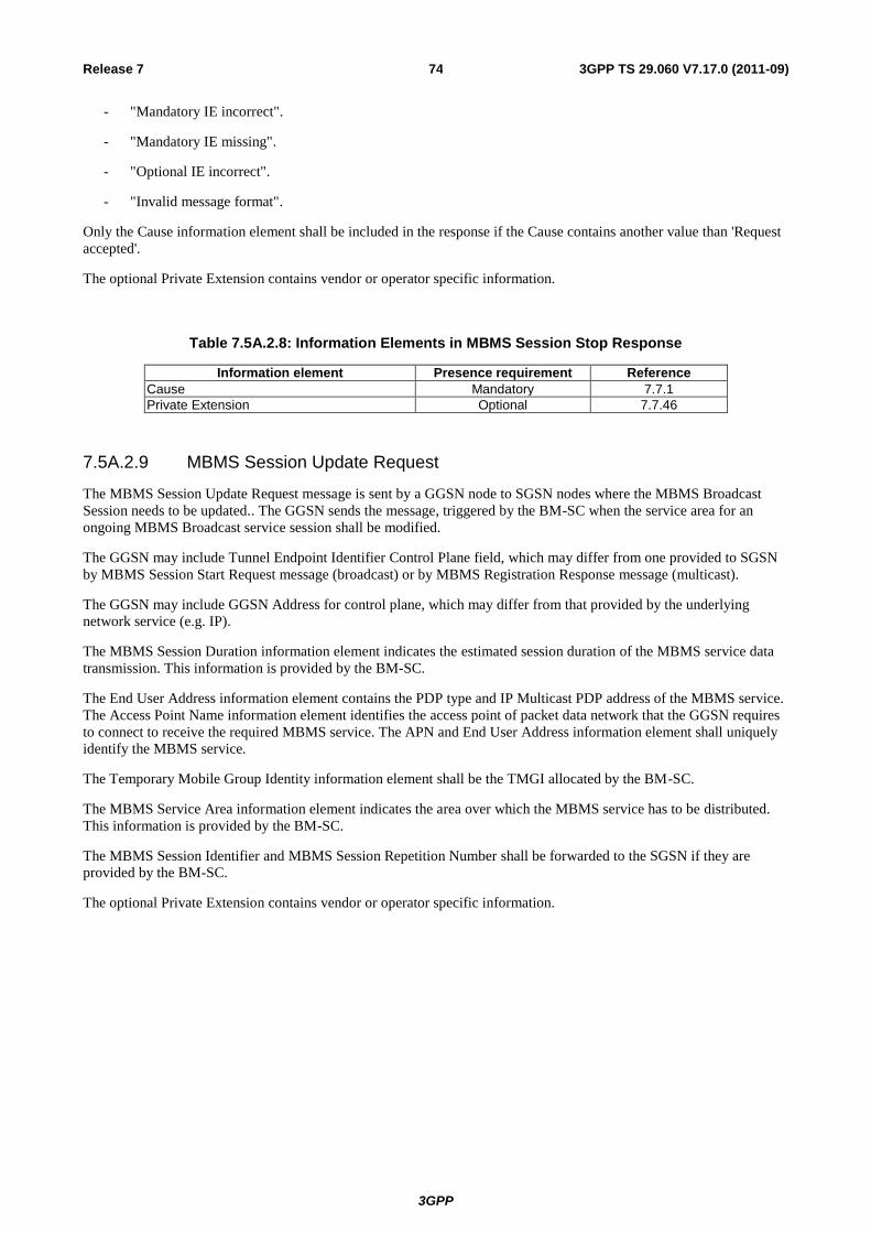
3GPP
3GPP TS 29.060 V7.17.0 (2011-09) 74 Release 7
- "Mandatory IE incorrect".
- "Mandatory IE missing".
- "Optional IE incorrect".
- "Invalid message format".
Only the Cause information element shall be included in the response if the Cause contains another value than 'Request
accepted'.
The optional Private Extension contains vendor or operator specific information.
Table 7.5A.2.8: Information Elements in MBMS Session Stop Response
Information element Presence requirement Reference
Cause Mandatory 7.7.1
Private Extension Optional 7.7.46
7.5A.2.9 MBMS Session Update Request
The MBMS Session Update Request message is sent by a GGSN node to SGSN nodes where the MBMS Broadcast
Session needs to be updated.. The GGSN sends the message, triggered by the BM-SC when the service area for an
ongoing MBMS Broadcast service session shall be modified.
The GGSN may include Tunnel Endpoint Identifier Control Plane field, which may differ from one provided to SGSN
by MBMS Session Start Request message (broadcast) or by MBMS Registration Response message (multicast).
The GGSN may include GGSN Address for control plane, which may differ from that provided by the underlying
network service (e.g. IP).
The MBMS Session Duration information element indicates the estimated session duration of the MBMS service data
transmission. This information is provided by the BM-SC.
The End User Address information element contains the PDP type and IP Multicast PDP address of the MBMS service.
The Access Point Name information element identifies the access point of packet data network that the GGSN requires
to connect to receive the required MBMS service. The APN and End User Address information element shall uniquely
identify the MBMS service.
The Temporary Mobile Group Identity information element shall be the TMGI allocated by the BM-SC.
The MBMS Service Area information element indicates the area over which the MBMS service has to be distributed.
This information is provided by the BM-SC.
The MBMS Session Identifier and MBMS Session Repetition Number shall be forwarded to the SGSN if they are
provided by the BM-SC.
The optional Private Extension contains vendor or operator specific information.
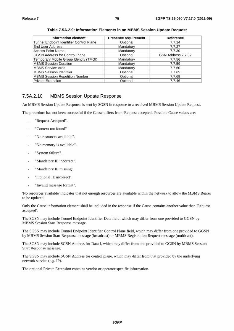
3GPP
3GPP TS 29.060 V7.17.0 (2011-09) 75 Release 7
Table 7.5A.2.9: Information Elements in an MBMS Session Update Request
Information element Presence requirement Reference
Tunnel Endpoint Identifier Control Plane Optional 7.7.14
End User Address Mandatory 7.7.27
Access Point Name Mandatory 7.7.30
GGSN Address for Control Plane Optional GSN Address 7.7.32
Temporary Mobile Group Identity (TMGI) Mandatory 7.7.56
MBMS Session Duration Mandatory 7.7.59
MBMS Service Area Mandatory 7.7.60
MBMS Session Identifier Optional 7.7.65
MBMS Session Repetition Number Optional 7.7.69
Private Extension Optional 7.7.46
7.5A.2.10 MBMS Session Update Response
An MBMS Session Update Response is sent by SGSN in response to a received MBMS Session Update Request.
The procedure has not been successful if the Cause differs from 'Request accepted'. Possible Cause values are:
- "Request Accepted".
- "Context not found"
- "No resources available".
- "No memory is available".
- "System failure".
- "Mandatory IE incorrect".
- "Mandatory IE missing".
- "Optional IE incorrect".
- "Invalid message format".
'No resources available' indicates that not enough resources are available within the network to allow the MBMS Bearer
to be updated.
Only the Cause information element shall be included in the response if the Cause contains another value than 'Request
accepted'.
The SGSN may include Tunnel Endpoint Identifier Data field, which may differ from one provided to GGSN by
MBMS Session Start Response message.
The SGSN may include Tunnel Endpoint Identifier Control Plane field, which may differ from one provided to GGSN
by MBMS Session Start Response message (broadcast) or MBMS Registration Request message (multicast).
The SGSN may include SGSN Address for Data I, which may differ from one provided to GGSN by MBMS Session
Start Response message.
The SGSN may include SGSN Address for control plane, which may differ from that provided by the underlying
network service (e.g. IP).
The optional Private Extension contains vendor or operator specific information.
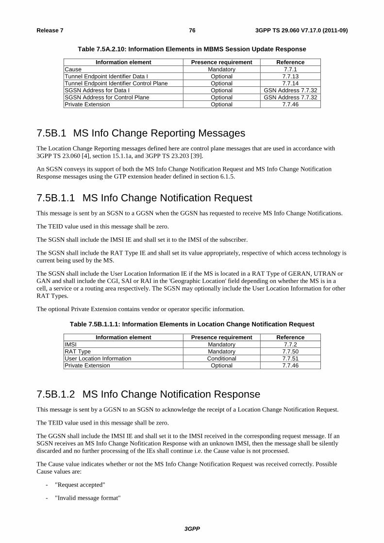
3GPP
3GPP TS 29.060 V7.17.0 (2011-09) 76 Release 7
Table 7.5A.2.10: Information Elements in MBMS Session Update Response
Information element Presence requirement Reference
Cause Mandatory 7.7.1
Tunnel Endpoint Identifier Data I Optional 7.7.13
Tunnel Endpoint Identifier Control Plane Optional 7.7.14
SGSN Address for Data I Optional GSN Address 7.7.32
SGSN Address for Control Plane Optional GSN Address 7.7.32
Private Extension Optional 7.7.46
7.5B.1 MS Info Change Reporting Messages
The Location Change Reporting messages defined here are control plane messages that are used in accordance with
3GPP TS 23.060 [4], section 15.1.1a, and 3GPP TS 23.203 [39].
An SGSN conveys its support of both the MS Info Change Notification Request and MS Info Change Notification
Response messages using the GTP extension header defined in section 6.1.5.
7.5B.1.1 MS Info Change Notification Request
This message is sent by an SGSN to a GGSN when the GGSN has requested to receive MS Info Change Notifications.
The TEID value used in this message shall be zero.
The SGSN shall include the IMSI IE and shall set it to the IMSI of the subscriber.
The SGSN shall include the RAT Type IE and shall set its value appropriately, respective of which access technology is
current being used by the MS.
The SGSN shall include the User Location Information IE if the MS is located in a RAT Type of GERAN, UTRAN or
GAN and shall include the CGI, SAI or RAI in the 'Geographic Location' field depending on whether the MS is in a
cell, a service or a routing area respectively. The SGSN may optionally include the User Location Information for other
RAT Types.
The optional Private Extension contains vendor or operator specific information.
Table 7.5B.1.1.1: Information Elements in Location Change Notification Request
Information element Presence requirement Reference
IMSI Mandatory 7.7.2
RAT Type Mandatory 7.7.50
User Location Information Conditional 7.7.51
Private Extension Optional 7.7.46
7.5B.1.2 MS Info Change Notification Response
This message is sent by a GGSN to an SGSN to acknowledge the receipt of a Location Change Notification Request.
The TEID value used in this message shall be zero.
The GGSN shall include the IMSI IE and shall set it to the IMSI received in the corresponding request message. If an
SGSN receives an MS Info Change Nofitication Response with an unknown IMSI, then the message shall be silently
discarded and no further processing of the IEs shall continue i.e. the Cause value is not processed.
The Cause value indicates whether or not the MS Info Change Notification Request was received correctly. Possible
Cause values are:
- "Request accepted"
- "Invalid message format"

3GPP
3GPP TS 29.060 V7.17.0 (2011-09) 77 Release 7
- "IMSI not known"
- "Mandatory IE incorrect"
- "Mandatory IE missing"
- "Optional IE incorrect"
- "System failure"
If the received MS Info Change Notification Response contains a Cause value of 'IMSI not known', then the MS Info
Change Reporting mechanism shall be stopped in the SGSN for all PDP Contexts associated with the IMSI received
and the GGSN from which the response was received. The SGSN shall then initiate an Update PDP Context for all of
these PDP Contexts associated with the GGSN.
For error handling if the received MS Info Change Notification Response contains a Cause value other than "Request
accepted", "IMSI not known" and "System failure", refer to clause 11.
If the MS Info Change Reporting mechanism is to be stopped for this subscriber in the SGSN, then the GGSN shall
include the MS Info Change Reporting Action IE in the message and shall set the value of the Action field
appropriately.
The optional Private Extension contains vendor or operator specific information.
Table 7.5B.1.2.1: Information Elements in Location Change Notification Response
Information element Presence requirement Reference
IMSI Mandatory 7.7.2
Cause Mandatory 7.7.1
MS Info Change Reporting Action Optional 7.7.80
Private Extension Optional 7.7.46
7.6 Reliable Delivery of Signalling Messages
Each path maintains a queue with signalling messages to be sent to the peer. The message at the front of the queue, if it
is a request for which a response has been defined, shall be sent with a Sequence Number, and shall be held in a path
list until a response is received. Each path has its own list. The Sequence Number shall be unique for each outstanding
request message sourced from the same IP/UDP endpoint. A GSN or RNC may have several outstanding requests while
waiting for responses.
The T3-RESPONSE timer shall be started when a signalling request message (for which a response has been defined) is
sent. A signalling message request or response has probably been lost if a response has not been received before the
T3-RESPONSE timer expires. The request is then retransmitted if the total number of request attempts is less than
N3-REQUESTS times. The timer shall be implemented in the control plane application as well as user plane application
for Echo Request / Echo Response. The wait time for a response (T3-RESPONSE timer value) and the number of
retries (N3-REQUESTS) shall be configurable per procedure. The total wait time shall be shorter than the MS wait time
between retries of Attach and RA Update messages.
For Intra Domain Connection of RAN Nodes to Multiple CN Nodes, an SGSN relaying a received Identification
Request message or a received SGSN Context Request message to another SGSN shall not supervise the Identification
Response message or the SGSN Context Response message respectively, i.e. the T3-RESPONSE timer shall not be
started in the SGSN relaying any of these two messages. Also, such an SGSN shall not modify the Sequence Number
when relaying the Identification Request message or the SGSN Context Request message.
All received request messages shall be responded to and all response messages associated with a certain request shall
always include the same information. Duplicated response messages shall be discarded, and, for the SGSN Context
Response case, the SGSN Context Acknowledge message shall be sent unless the SGSN Context Request was rejected.
A response message without a matching outstanding request should be considered as a duplicate.
The Forward Relocation Complete and Forward SRNS Context messages shall be treated as signalling request
messages. The SGSN Context Acknowledge, Forward Relocation Complete Acknowledge and Forward SRNS Context
Acknowledge messages shall be treated as response messages.

3GPP
3GPP TS 29.060 V7.17.0 (2011-09) 78 Release 7
The SGSN Context Response message needs special treatment by the old SGSN and New SGSN.
The New SGSN must consider this as a regular response to the outstanding SGSN Context Request message, but also
copy the sequence number in the header of the SGSN Context Acknowledge it shall send back to the old SGSN unless
the SGSN Context Request was rejected. The Old SG SN, when it expects the new SGSN to send back a SGSN Context
Acknowledge in response to a SGSN Context Response, shall keep track of the SGSN Context Response message
sequence number and apply to this message the rules valid for a Request message too. If a GSN or RNC is not
successful with the transfer of a signalling message, e.g. a Create PDP Context Request message, it shall inform the
upper layer of the unsuccessful transfer so that the controlling upper entity may take the necessary measures.
7.7 Information Elements
A GTP Signalling message may contain several information elements. The TLV (Type, Length, Value) or TV (Type,
Value) encoding format shall be used for the GTP information elements. The information elements shall be sorted, with
the Type fields in ascending order, in the signalling messages. The Length field contains the length of the information
element excluding the Type and Length field.
For all the length fields, bit 8 of the lowest numbered octet is the most significant bit and bit 1 of the highest numbered
octet is the least significant bit.
Within information elements, certain fields may be described as spare. These bits shall be transmitted with the value
defined for them. To allow for future features, the receiver shall not evaluate these bits.
The most significant bit in the Type field is set to 0 when the TV format is used and set to 1 for the TLV format.
Type -> TV format
8 7 6 4 3 2 15
Bits
Octets
10
Type -> TLV format
8 7 6 4 3 2 15
Bits
Octets
11
Figure 8: Type field for TV and TLV format
Table 37: Information Elements
IE Type Value
Format Information Element Reference
1 TV Cause 7.7.1
2 TV International Mobile Subscriber Identity (IMSI)
7.7.2
3 TV Routeing Area Identity (RAI) 7.7.3
4 TV Temporary Logical Link Identity (TLLI) 7.7.4
5 TV Packet TMSI (P-TMSI) 7.7.5
6-7 Spare
8 TV Reordering Required 7.7.6
9 TV Authentication Triplet 7.7.7
10 Spare
11 TV MAP Cause 7.7.8
12 TV P-TMSI Signature 7.7.9
13 TV MS Validated 7.7.10
14 TV Recovery 7.7.11
15 TV Selection Mode 7.7.12
16 TV Tunnel Endpoint Identifier Data I 7.7.13
17 TV Tunnel Endpoint Identifier Control Plane 7.7.14
18 TV Tunnel Endpoint Identifier Data II 7.7.15
19 TV Teardown Ind 7.7.16
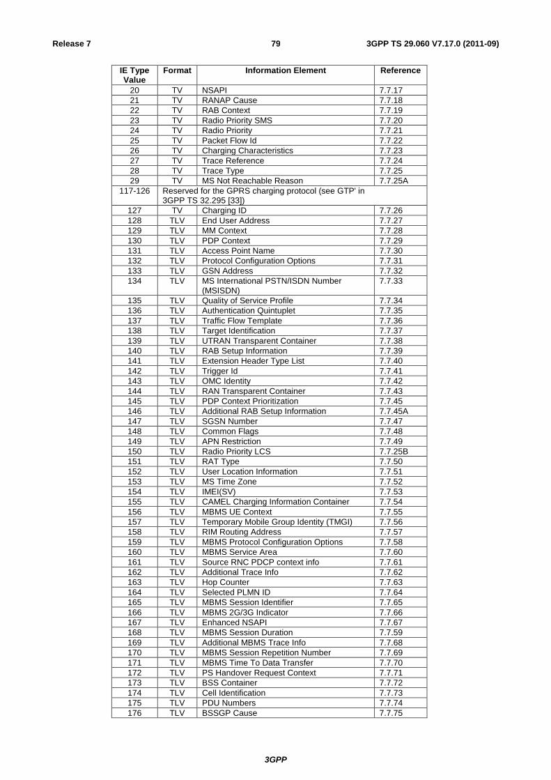
3GPP
3GPP TS 29.060 V7.17.0 (2011-09) 79 Release 7
IE Type Value
Format Information Element Reference
20 TV NSAPI 7.7.17
21 TV RANAP Cause 7.7.18
22 TV RAB Context 7.7.19
23 TV Radio Priority SMS 7.7.20
24 TV Radio Priority 7.7.21
25 TV Packet Flow Id 7.7.22
26 TV Charging Characteristics 7.7.23
27 TV Trace Reference 7.7.24
28 TV Trace Type 7.7.25
29 TV MS Not Reachable Reason 7.7.25A
117-126 Reserved for the GPRS charging protocol (see GTP' in 3GPP TS 32.295 [33])
127 TV Charging ID 7.7.26
128 TLV End User Address 7.7.27
129 TLV MM Context 7.7.28
130 TLV PDP Context 7.7.29
131 TLV Access Point Name 7.7.30
132 TLV Protocol Configuration Options 7.7.31
133 TLV GSN Address 7.7.32
134 TLV MS International PSTN/ISDN Number (MSISDN)
7.7.33
135 TLV Quality of Service Profile 7.7.34
136 TLV Authentication Quintuplet 7.7.35
137 TLV Traffic Flow Template 7.7.36
138 TLV Target Identification 7.7.37
139 TLV UTRAN Transparent Container 7.7.38
140 TLV RAB Setup Information 7.7.39
141 TLV Extension Header Type List 7.7.40
142 TLV Trigger Id 7.7.41
143 TLV OMC Identity 7.7.42
144 TLV RAN Transparent Container 7.7.43
145 TLV PDP Context Prioritization 7.7.45
146 TLV Additional RAB Setup Information 7.7.45A
147 TLV SGSN Number 7.7.47
148 TLV Common Flags 7.7.48
149 TLV APN Restriction 7.7.49
150 TLV Radio Priority LCS 7.7.25B
151 TLV RAT Type 7.7.50
152 TLV User Location Information 7.7.51
153 TLV MS Time Zone 7.7.52
154 TLV IMEI(SV) 7.7.53
155 TLV CAMEL Charging Information Container 7.7.54
156 TLV MBMS UE Context 7.7.55
157 TLV Temporary Mobile Group Identity (TMGI) 7.7.56
158 TLV RIM Routing Address 7.7.57
159 TLV MBMS Protocol Configuration Options 7.7.58
160 TLV MBMS Service Area 7.7.60
161 TLV Source RNC PDCP context info 7.7.61
162 TLV Additional Trace Info 7.7.62
163 TLV Hop Counter 7.7.63
164 TLV Selected PLMN ID 7.7.64
165 TLV MBMS Session Identifier 7.7.65
166 TLV MBMS 2G/3G Indicator 7.7.66
167 TLV Enhanced NSAPI 7.7.67
168 TLV MBMS Session Duration 7.7.59
169 TLV Additional MBMS Trace Info 7.7.68
170 TLV MBMS Session Repetition Number 7.7.69
171 TLV MBMS Time To Data Transfer 7.7.70
172 TLV PS Handover Request Context 7.7.71
173 TLV BSS Container 7.7.72
174 TLV Cell Identification 7.7.73
175 TLV PDU Numbers 7.7.74
176 TLV BSSGP Cause 7.7.75

3GPP
3GPP TS 29.060 V7.17.0 (2011-09) 80 Release 7
IE Type Value
Format Information Element Reference
177 TLV Required MBMS bearer capabilities 7.7.76
178 TLV RIM Routing Address Discriminator 7.7.77
179 TLV List of set-up PFCs 7.7.78
180 TLV PS Handover XID Parameters 7.7.79
181 TLV MS Info Change Reporting Action 7.7.80
182 TLV Direct Tunnel Flags 7.7.81
183 TLV Correlation-ID 7.7.82
184 TLV Bearer Control Mode 7.7.83
185
186
187
199 TLV Reliable INTER RAT HANDOVER INFO 7.7.84
239-250 Reserved for the GPRS charging protocol (see GTP' in 3GPP TS 32.295 [33])
251 TLV Charging Gateway Address 7.7.44
252-254 Reserved for the GPRS charging protocol (see GTP' in 3GPP TS 32.295 [33])
255 TLV Private Extension 7.7.46
7.7.1 Cause
In a request, the Cause Value indicates the reason for the request. The Cause shall be included in the request message.
In a response, the Cause Value indicates the acceptance or the rejection of the corresponding request. In addition, the
Cause Value may indicate what was the reason for the corresponding request. The Cause value shall be included in the
response message.
Cause values are shared with the GTP’ protocol specified in 3GPP TS 32.295 [33].
'Request accepted' is returned when a GSN has accepted a control plane request.
'Non-existent' indicates a non-existent or an inactive PDP context.
'IMSI not known' indicates a non-existent MM context.
'MS is GPRS Detached' indicates an idle MM context.
'MS is not GPRS Responding' and 'MS Refuses' may be used by SGSN to reject a Network-Requested PDP Context
Activation.
'Version not supported' is returned when the recipient does not recognise the version number in the request message.
'Request IMSI', 'Request IMEI', 'Request IMSI and IMEI' and 'No identity needed' are used by GGSN to notify SGSN
what to do.
'No resources available' is a generic temporary error condition indicating that some kind of resource is used up for that
moment excluding the conditions all dynamic PDP addresses are occupied and no memory is available.
'All dynamic PDP addresses occupied' indicates that the GSN does not have a free dynamic PDP address to allocate any
longer.
'No memory available' indicates that the GSN does not have enough memory to use.
'Service not supported' is a generic error indicated that the GSN do not support the requested service.
'User authentication failed' indicates that the external packet network has rejected the user's service request.
'System failure' is a generic permanent error condition.
'Roaming restriction' indicates that the SGSN cannot activate the requested PDP context because of the roaming
restrictions.
'P-TMSI Signature mismatch' is returned if either:
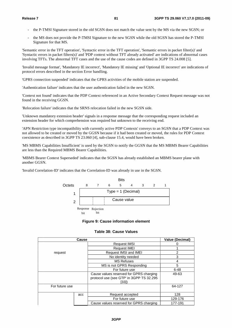
3GPP
3GPP TS 29.060 V7.17.0 (2011-09) 81 Release 7
- the P-TMSI Signature stored in the old SGSN does not match the value sent by the MS via the new SGSN; or
- the MS does not provide the P-TMSI Signature to the new SGSN while the old SGSN has stored the P-TMSI
Signature for that MS.
'Semantic error in the TFT operation', 'Syntactic error in the TFT operation', 'Semantic errors in packet filter(s)' and
'Syntactic errors in packet filters(s)' and 'PDP context without TFT already activated' are indications of abnormal cases
involving TFTs. The abnormal TFT cases and the use of the cause codes are defined in 3GPP TS 24.008 [5].
'Invalid message format', 'Mandatory IE incorrect', 'Mandatory IE missing' and 'Optional IE incorrect' are indications of
protocol errors described in the section Error handling.
'GPRS connection suspended' indicates that the GPRS activities of the mobile station are suspended.
'Authentication failure' indicates that the user authentication failed in the new SGSN.
'Context not found' indicates that the PDP Context referenced in an Active Secondary Context Request message was not
found in the receiving GGSN.
'Relocation failure' indicates that the SRNS relocation failed in the new SGSN side.
'Unknown mandatory extension header' signals in a response message that the corresponding request included an
extension header for which comprehension was required but unknown to the receiving end.
'APN Restriction type incompatibility with currently active PDP Contexts' conveys to an SGSN that a PDP Context was
not allowed to be created or moved by the GGSN because if it had been created or moved, the rules for PDP Context
coexistence as described in 3GPP TS 23.060 [4], sub-clause 15.4, would have been broken.
'MS MBMS Capabilities Insufficient' is used by the SGSN to notify the GGSN that the MS MBMS Bearer Capabilities
are less than the Required MBMS Bearer Capabilities.
'MBMS Bearer Context Superseded' indicates that the SGSN has already established an MBMS bearer plane with
another GGSN.
'Invalid Correlation-ID' indicates that the Correlation-ID was already in use in the SGSN.
Cause value
Type = 1 (Decimal)
8 7 6 4 3 2 1 5
Bits
Octets
2
1
Response
bit Rejection
bit
Table 38: Cause Values
Cause Value (Decimal)
Request IMSI 0
Request IMEI 1
request Request IMSI and IMEI 2
No identity needed 3
MS Refuses 4
MS is not GPRS Responding 5
For future use 6-48
Cause values reserved for GPRS charging protocol use (see GTP' in 3GPP TS 32.295
[33])
49-63
For future use
64-127
acc Request accepted 128
For future use 129-176
Cause values reserved for GPRS charging 177-191
Figure 9: Cause information element

3GPP
3GPP TS 29.060 V7.17.0 (2011-09) 82 Release 7
Cause Value (Decimal)
protocol use (see GTP' in 3GPP TS 32.295 [33])
Non-existent 192
Invalid message format 193
response rej IMSI not known 194
MS is GPRS Detached 195
MS is not GPRS Responding 196
MS Refuses 197
Version not supported 198
No resources available 199
Service not supported 200
Mandatory IE incorrect 201
Mandatory IE missing 202
Optional IE incorrect 203
System failure 204
Roaming restriction 205
P-TMSI Signature mismatch 206
GPRS connection suspended 207
Authentication failure 208
User authentication failed 209
Context not found 210
All dynamic PDP addresses are occupied 211
No memory is available 212
Relocation failure 213
Unknown mandatory extension header 214
Semantic error in the TFT operation 215
Syntactic error in the TFT operation 216
Semantic errors in packet filter(s) 217
Syntactic errors in packet filter(s) 218
Missing or unknown APN 219
Unknown PDP address or PDP type 220
PDP context without TFT already activated 221
APN access denied – no subscription 222
APN Restriction type incompatibility with currently active PDP Contexts
223
MS MBMS Capabilities Insufficient 224
Invalid Correlation-ID 225
MBMS Bearer Context Superseded 226
For future use 227-240
Cause values reserved for GPRS charging protocol use (see GTP' in 3GPP TS 32.295
[33])
241-255
NOTE: With this coding, bits 8 and 7 of the Cause Value respectively indicate whether the message was a request or a response, and whether the request was accepted or rejected.
Table 39: Use of the Cause Values
Cause 8 value bits 7 Result
0 0 Request
0 1 For future use (note)
1 0 Acceptance
1 1 Rejection
NOTE: The value '01' is for future use and shall not be sent. If received in a response, it shall be treated as a rejection.
7.7.2 International Mobile Subscriber Identity (IMSI)
The IMSI shall be the subscriber identity of the MS. The IMSI is defined in 3GPP TS 23.003 [2].
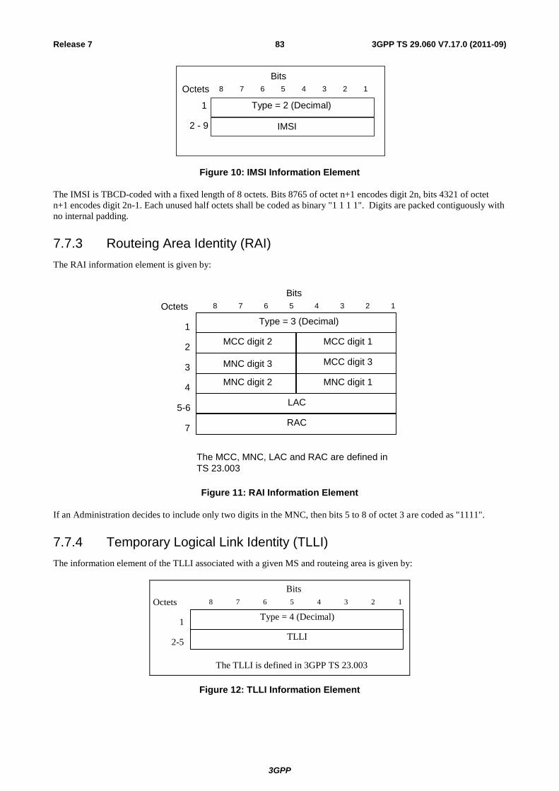
3GPP
3GPP TS 29.060 V7.17.0 (2011-09) 83 Release 7
8 7 6 4 3 2 1 5
Bits
Octets
2 - 9
1
IMSI
Type = 2 (Decimal)
Figure 10: IMSI Information Element
The IMSI is TBCD-coded with a fixed length of 8 octets. Bits 8765 of octet n+1 encodes digit 2n, bits 4321 of octet
n+1 encodes digit 2n-1. Each unused half octets shall be coded as binary "1 1 1 1". Digits are packed contiguously with
no internal padding.
7.7.3 Routeing Area Identity (RAI)
The RAI information element is given by:
RAC
LAC
MCC digit 1MCC digit 2
Type = 3 (Decimal)
MNC digit 1
MCC digit 3
MNC digit 2
8 7 6 4 3 2 15
Bits
Octets
5-6
7
4
3
2
1
The MCC, MNC, LAC and RAC are defined in
TS 23.003
MNC digit 3
Figure 11: RAI Information Element
If an Administration decides to include only two digits in the MNC, then bits 5 to 8 of octet 3 are coded as "1111".
7.7.4 Temporary Logical Link Identity (TLLI)
The information element of the TLLI associated with a given MS and routeing area is given by:
Type = 4 (Decimal)
8 7 6 4 3 2 1 5
Bits
Octets
2-5
1
TLLI
The TLLI is defined in 3GPP TS 23.003
Figure 12: TLLI Information Element
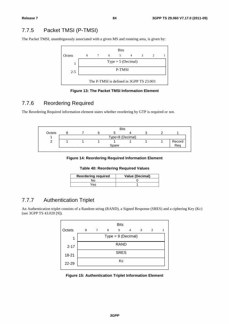
3GPP
3GPP TS 29.060 V7.17.0 (2011-09) 84 Release 7
7.7.5 Packet TMSI (P-TMSI)
The Packet TMSI, unambiguously associated with a given MS and routeing area, is given by:
Type = 5 (Decimal)
8 7 6 4 3 2 1 5
Bits
Octets
2-5
1
P-TMSI
The P-TMSI is defined in 3GPP TS 23.003
7.7.6 Reordering Required
The Reordering Required information element states whether reordering by GTP is required or not.
Bits Octets 8 7 6 5 4 3 2 1
1 Type=8 (Decimal)
2 1 1 1 1 Spare
1 1 1 Record Req
Figure 14: Reordering Required Information Element
Table 40: Reordering Required Values
Reordering required Value (Decimal)
No 0
Yes 1
7.7.7 Authentication Triplet
An Authentication triplet consists of a Random string (RAND), a Signed Response (SRES) and a ciphering Key (Kc)
(see 3GPP TS 43.020 [9]).
Type = 9 (Decimal)
RAND
8 7 6 4 3 2 15
Bits
Octets
2-17
1
SRES
Kc
18-21
22-29
Figure 15: Authentication Triplet Information Element
Figure 13: The Packet TMSI Information Element
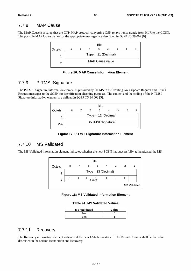
3GPP
3GPP TS 29.060 V7.17.0 (2011-09) 85 Release 7
7.7.8 MAP Cause
The MAP Cause is a value that the GTP-MAP protocol-converting GSN relays transparently from HLR to the GGSN.
The possible MAP Cause values for the appropriate messages are described in 3GPP TS 29.002 [6].
MAP Cause value
Type = 11 (Decimal)
8 7 6 4 3 2 15
Bits
Octets
2
1
Figure 16: MAP Cause Information Element
7.7.9 P-TMSI Signature
The P-TMSI Signature information element is provided by the MS in the Routing Area Update Request and Attach
Request messages to the SGSN for identification checking purposes. The content and the coding of the P-TMSI
Signature information element are defined in 3GPP TS 24.008 [5].
P-TMSI Signature
Type = 12 (Decimal)
8 7 6 4 3 2 15
Bits
Octets
2-4
1
Figure 17: P-TMSI Signature Information Element
7.7.10 MS Validated
The MS Validated information element indicates whether the new SGSN has successfully authenticated the MS.
8 7 6 4 3 2 15
Bits
Octets
2
1Type = 13 (Decimal)
1 1 1 1 1 1 1Spare
MS Validated
Figure 18: MS Validated Information Element
Table 41: MS Validated Values
MS Validated Value
No 0
Yes 1
7.7.11 Recovery
The Recovery information element indicates if the peer GSN has restarted. The Restart Counter shall be the value
described in the section Restoration and Recovery.
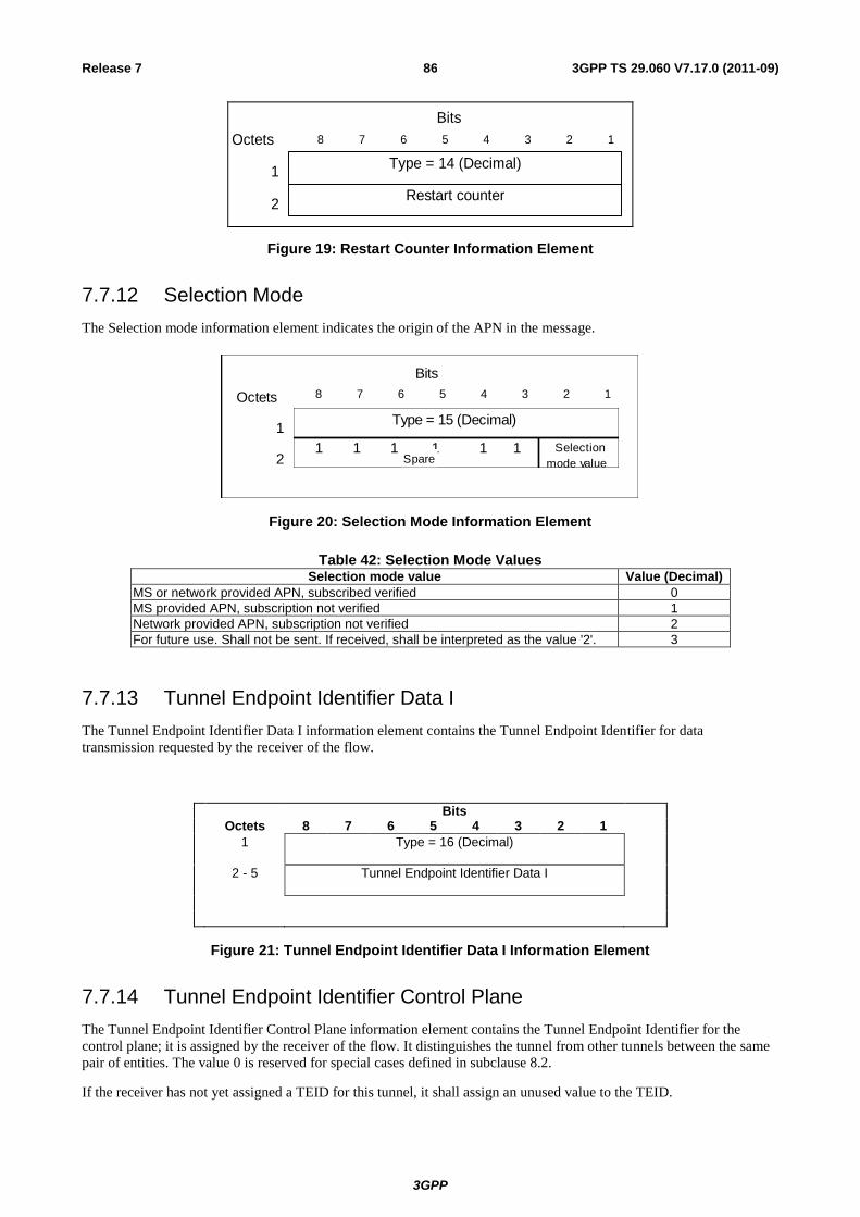
3GPP
3GPP TS 29.060 V7.17.0 (2011-09) 86 Release 7
Restart counter
Type = 14 (Decimal)
8 7 6 4 3 2 15
Bits
Octets
2
1
Figure 19: Restart Counter Information Element
7.7.12 Selection Mode
The Selection mode information element indicates the origin of the APN in the message.
8 7 6 4 3 2 15
Bits
Octets
2
1Type = 15 (Decimal)
1 1 1 1 1 1Spare
Selection
mode value
Figure 20: Selection Mode Information Element
Table 42: Selection Mode ValuesSelection mode value Value (Decimal)
MS or network provided APN, subscribed verified 0
MS provided APN, subscription not verified 1
Network provided APN, subscription not verified 2
For future use. Shall not be sent. If received, shall be interpreted as the value '2'. 3
7.7.13 Tunnel Endpoint Identifier Data I
The Tunnel Endpoint Identifier Data I information element contains the Tunnel Endpoint Identifier for data
transmission requested by the receiver of the flow.
Bits Octets 8 7 6 5 4 3 2 1
1 Type = 16 (Decimal)
2 - 5 Tunnel Endpoint Identifier Data I
Figure 21: Tunnel Endpoint Identifier Data I Information Element
7.7.14 Tunnel Endpoint Identifier Control Plane
The Tunnel Endpoint Identifier Control Plane information element contains the Tunnel Endpoint Identifier for the
control plane; it is assigned by the receiver of the flow. It distinguishes the tunnel from other tunnels between the same
pair of entities. The value 0 is reserved for special cases defined in subclause 8.2.
If the receiver has not yet assigned a TEID for this tunnel, it shall assign an unused value to the TEID.
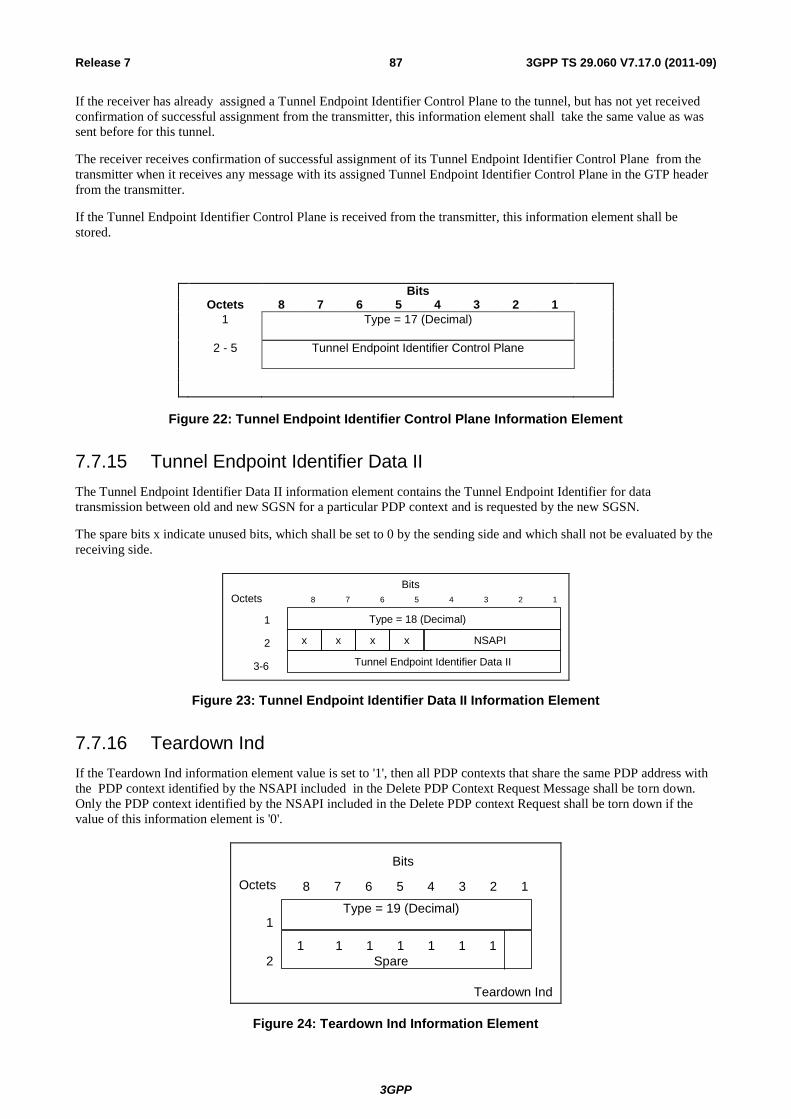
3GPP
3GPP TS 29.060 V7.17.0 (2011-09) 87 Release 7
If the receiver has already assigned a Tunnel Endpoint Identifier Control Plane to the tunnel, but has not yet received
confirmation of successful assignment from the transmitter, this information element shall take the same value as was
sent before for this tunnel.
The receiver receives confirmation of successful assignment of its Tunnel Endpoint Identifier Control Plane from the
transmitter when it receives any message with its assigned Tunnel Endpoint Identifier Control Plane in the GTP header
from the transmitter.
If the Tunnel Endpoint Identifier Control Plane is received from the transmitter, this information element shall be
stored.
Bits Octets 8 7 6 5 4 3 2 1
1 Type = 17 (Decimal)
2 - 5 Tunnel Endpoint Identifier Control Plane
Figure 22: Tunnel Endpoint Identifier Control Plane Information Element
7.7.15 Tunnel Endpoint Identifier Data II
The Tunnel Endpoint Identifier Data II information element contains the Tunnel Endpoint Identifier for data
transmission between old and new SGSN for a particular PDP context and is requested by the new SGSN.
The spare bits x indicate unused bits, which shall be set to 0 by the sending side and which shall not be evaluated by the
receiving side.
Type = 18 (Decimal)
8 7 6 4 3 2 1 5 Bits
Octets
1
x
3-6
2 x x
Tunnel Endpoint Identifier Data II
NSAPI x
Figure 23: Tunnel Endpoint Identifier Data II Information Element
7.7.16 Teardown Ind
If the Teardown Ind information element value is set to '1', then all PDP contexts that share the same PDP address with
the PDP context identified by the NSAPI included in the Delete PDP Context Request Message shall be torn down.
Only the PDP context identified by the NSAPI included in the Delete PDP context Request shall be torn down if the
value of this information element is '0'.
Type = 19 (Decimal)
8 7 6 4 3 2 5
Bits
Octets
1
2
1
1 1 1 1 1 1 1
Spare
Teardown Ind
Figure 24: Teardown Ind Information Element
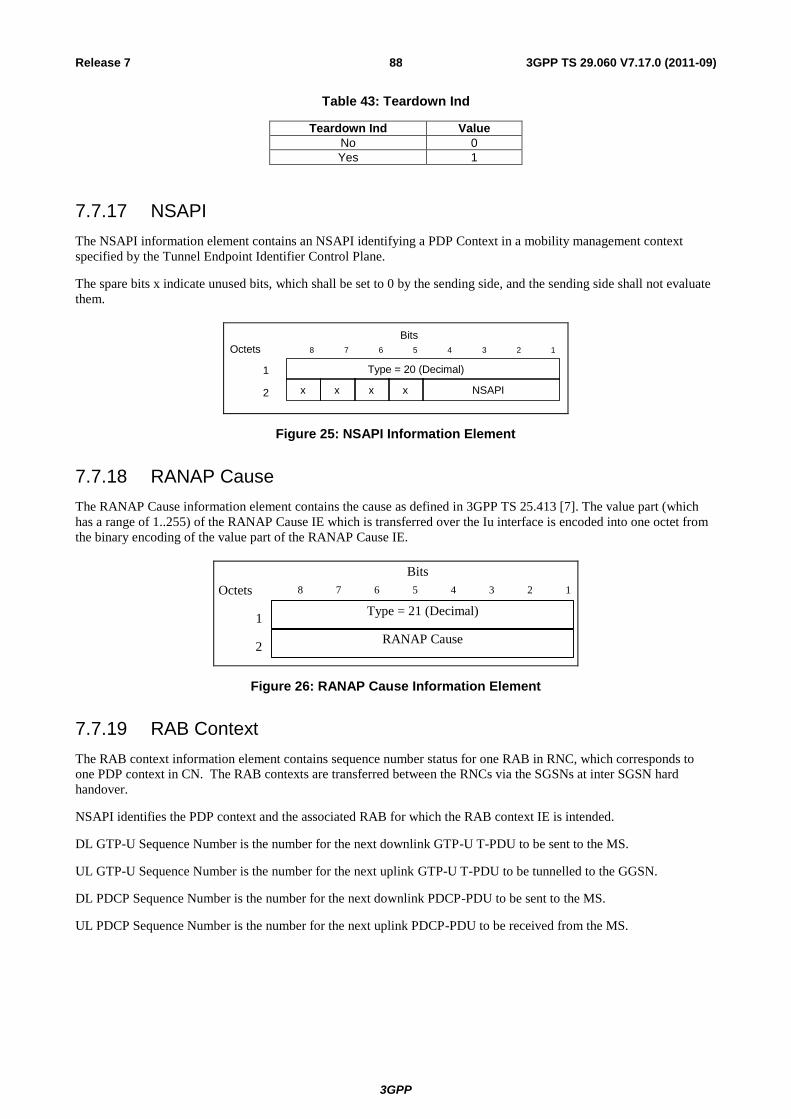
3GPP
3GPP TS 29.060 V7.17.0 (2011-09) 88 Release 7
Table 43: Teardown Ind
Teardown Ind Value
No 0
Yes 1
7.7.17 NSAPI
The NSAPI information element contains an NSAPI identifying a PDP Context in a mobility management context
specified by the Tunnel Endpoint Identifier Control Plane.
The spare bits x indicate unused bits, which shall be set to 0 by the sending side, and the sending side shall not evaluate
them.
Type = 20 (Decimal)
8 7 6 4 3 2 1 5 Bits
Octets
1
x 2 x x
NSAPI x
Figure 25: NSAPI Information Element
7.7.18 RANAP Cause
The RANAP Cause information element contains the cause as defined in 3GPP TS 25.413 [7]. The value part (which
has a range of 1..255) of the RANAP Cause IE which is transferred over the Iu interface is encoded into one octet from
the binary encoding of the value part of the RANAP Cause IE.
Type = 21 (Decimal)
RANAP Cause
8 7 6 4 3 2 15
Bits
Octets
2
1
Figure 26: RANAP Cause Information Element
7.7.19 RAB Context
The RAB context information element contains sequence number status for one RAB in RNC, which corresponds to
one PDP context in CN. The RAB contexts are transferred between the RNCs via the SGSNs at inter SGSN hard
handover.
NSAPI identifies the PDP context and the associated RAB for which the RAB context IE is intended.
DL GTP-U Sequence Number is the number for the next downlink GTP-U T-PDU to be sent to the MS.
UL GTP-U Sequence Number is the number for the next uplink GTP-U T-PDU to be tunnelled to the GGSN.
DL PDCP Sequence Number is the number for the next downlink PDCP-PDU to be sent to the MS.
UL PDCP Sequence Number is the number for the next uplink PDCP-PDU to be received from the MS.
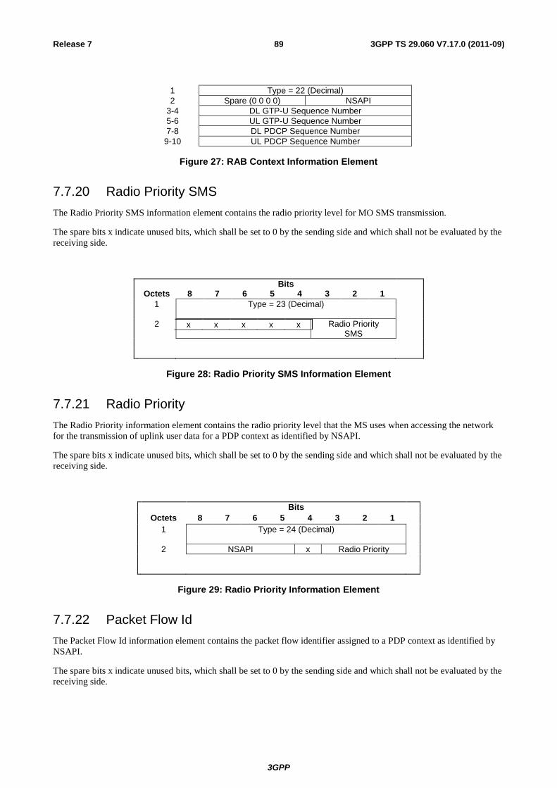
3GPP
3GPP TS 29.060 V7.17.0 (2011-09) 89 Release 7
1 Type = 22 (Decimal)
2 Spare (0 0 0 0) NSAPI
3-4 DL GTP-U Sequence Number
5-6 UL GTP-U Sequence Number
7-8 DL PDCP Sequence Number
9-10 UL PDCP Sequence Number
Figure 27: RAB Context Information Element
7.7.20 Radio Priority SMS
The Radio Priority SMS information element contains the radio priority level for MO SMS transmission.
The spare bits x indicate unused bits, which shall be set to 0 by the sending side and which shall not be evaluated by the
receiving side.
Bits Octets 8 7 6 5 4 3 2 1
1 Type = 23 (Decimal)
2 x x x x x
Radio Priority SMS
Figure 28: Radio Priority SMS Information Element
7.7.21 Radio Priority
The Radio Priority information element contains the radio priority level that the MS uses when accessing the network
for the transmission of uplink user data for a PDP context as identified by NSAPI.
The spare bits x indicate unused bits, which shall be set to 0 by the sending side and which shall not be evaluated by the
receiving side.
Bits Octets 8 7 6 5 4 3 2 1 1 Type = 24 (Decimal)
2 NSAPI x Radio Priority
Figure 29: Radio Priority Information Element
7.7.22 Packet Flow Id
The Packet Flow Id information element contains the packet flow identifier assigned to a PDP context as identified by
NSAPI.
The spare bits x indicate unused bits, which shall be set to 0 by the sending side and which shall not be evaluated by the
receiving side.
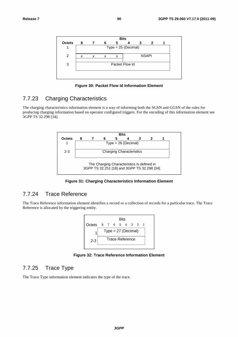
3GPP
3GPP TS 29.060 V7.17.0 (2011-09) 90 Release 7
Bits Octets 8 7 6 5 4 3 2 1
1 Type = 25 (Decimal)
2 x x x x
NSAPI
3 Packet Flow Id
Figure 30: Packet Flow Id Information Element
7.7.23 Charging Characteristics
The charging characteristics information element is a way of informing both the SGSN and GGSN of the rules for
producing charging information based on operator configured triggers. For the encoding of this information element see
3GPP TS 32.298 [34].
Bits Octets 8 7 6 5 4 3 2 1
1 Type = 26 (Decimal)
2-3 Charging Characteristics
The Charging Characteristics is defined in
3GPP TS 32.251 [18] and 3GPP TS 32.298 [34].
Figure 31: Charging Characteristics Information Element
7.7.24 Trace Reference
The Trace Reference information element identifies a record or a collection of records for a particular trace. The Trace
Reference is allocated by the triggering entity.
Trace Reference
Type = 27 (Decimal)
8 7 6 4 3 2 1 5
Bits
Octets
2-3
1
Figure 32: Trace Reference Information Element
7.7.25 Trace Type
The Trace Type information element indicates the type of the trace.
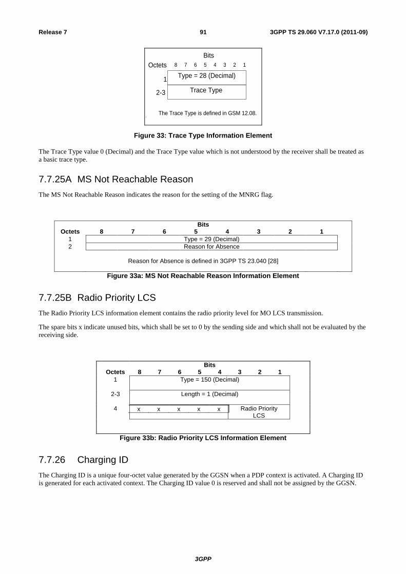
3GPP
3GPP TS 29.060 V7.17.0 (2011-09) 91 Release 7
Trace Type
Type = 28 (Decimal)
8 7 6 4 3 2 1 5
Bits
Octets
2-3
1
The Trace Type is defined in GSM 12.08.
Figure 33: Trace Type Information Element
The Trace Type value 0 (Decimal) and the Trace Type value which is not understood by the receiver shall be treated as
a basic trace type.
7.7.25A MS Not Reachable Reason
The MS Not Reachable Reason indicates the reason for the setting of the MNRG flag.
Bits Octets 8 7 6 5 4 3 2 1
1 Type = 29 (Decimal)
2 Reason for Absence
Reason for Absence is defined in 3GPP TS 23.040 [28]
Figure 33a: MS Not Reachable Reason Information Element
7.7.25B Radio Priority LCS
The Radio Priority LCS information element contains the radio priority level for MO LCS transmission.
The spare bits x indicate unused bits, which shall be set to 0 by the sending side and which shall not be evaluated by the
receiving side.
Bits Octets 8 7 6 5 4 3 2 1
1 Type = 150 (Decimal)
2-3 Length = 1 (Decimal)
4 x x x x x
Radio Priority LCS
Figure 33b: Radio Priority LCS Information Element
7.7.26 Charging ID
The Charging ID is a unique four-octet value generated by the GGSN when a PDP context is activated. A Charging ID
is generated for each activated context. The Charging ID value 0 is reserved and shall not be assigned by the GGSN.
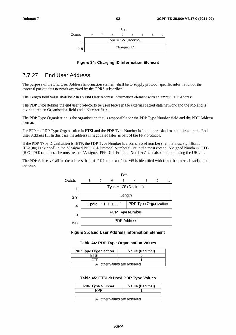
3GPP
3GPP TS 29.060 V7.17.0 (2011-09) 92 Release 7
Charging ID
Type = 127 (Decimal)
8 7 6 4 3 2 15
Bits
Octets
2-5
1
Figure 34: Charging ID Information Element
7.7.27 End User Address
The purpose of the End User Address information element shall be to supply protocol specific information of the
external packet data network accessed by the GPRS subscriber.
The Length field value shall be 2 in an End User Address information element with an empty PDP Address.
The PDP Type defines the end user protocol to be used between the external packet data network and the MS and is
divided into an Organisation field and a Number field.
The PDP Type Organisation is the organisation that is responsible for the PDP Type Number field and the PDP Address
format.
For PPP the PDP Type Organisation is ETSI and the PDP Type Number is 1 and there shall be no address in the End
User Address IE. In this case the address is negotiated later as part of the PPP protocol.
If the PDP Type Organisation is IETF, the PDP Type Number is a compressed number (i.e. the most significant
HEX(00) is skipped) in the "Assigned PPP DLL Protocol Numbers" list in the most recent "Assigned Numbers" RFC
(RFC 1700 or later). The most recent "Assigned PPP DLL Protocol Numbers" can also be found using the URL = .
The PDP Address shall be the address that this PDP context of the MS is identified with from the external packet data
network.
PDP Type Organization
PDP Address
Length
Type = 128 (Decimal)
8 7 6 4 3 2 15
Bits
Octets
2-3
5
4
1
PDP Type Number
6-n
Spare „ 1 1 1 1 ‟
Figure 35: End User Address Information Element
Table 44: PDP Type Organisation Values
PDP Type Organisation Value (Decimal)
ETSI 0
IETF 1
All other values are reserved
Table 45: ETSI defined PDP Type Values
PDP Type Number Value (Decimal)
PPP 1
All other values are reserved
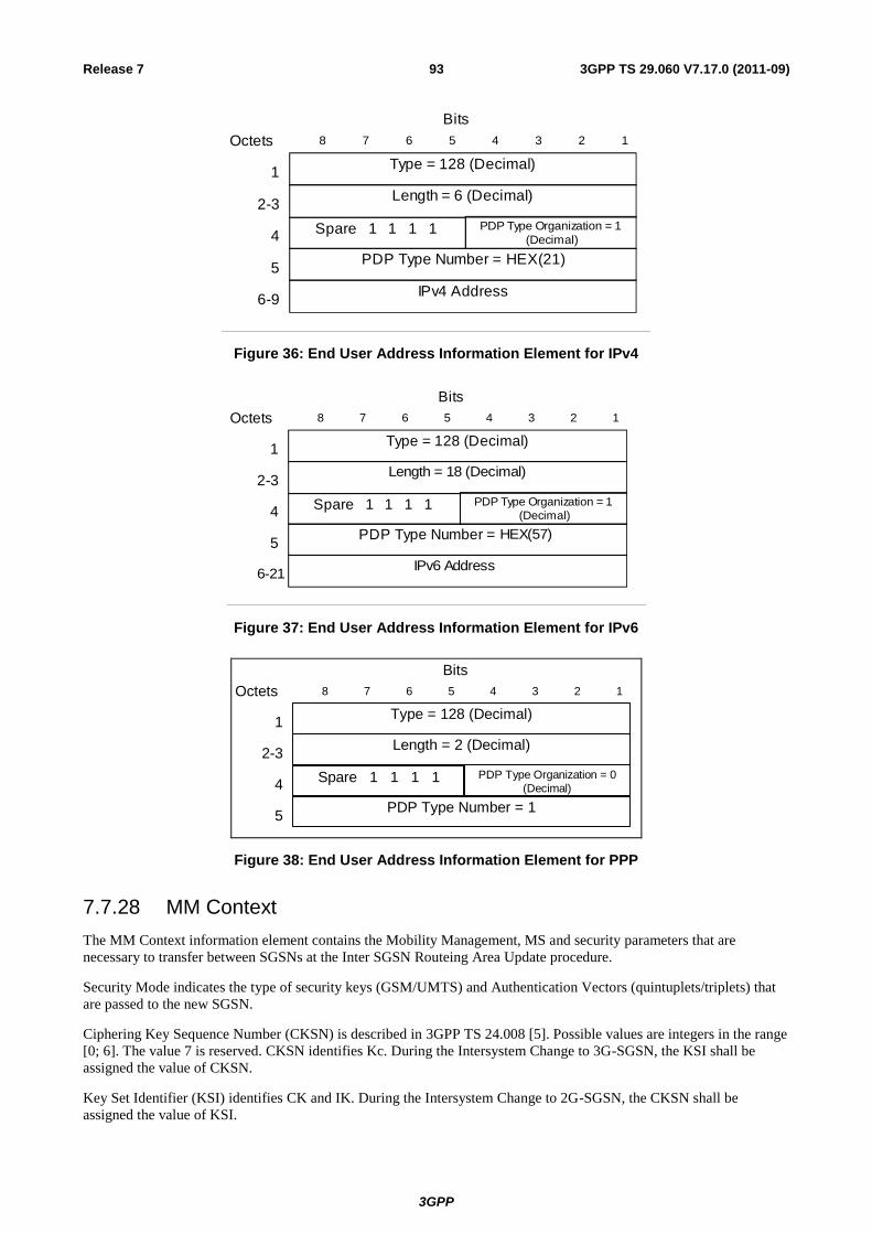
3GPP
3GPP TS 29.060 V7.17.0 (2011-09) 93 Release 7
Type = 128 (Decimal)
PDP Type Number = HEX(21)
IPv4 Address
Length = 6 (Decimal)
8 7 6 4 3 2 15
Bits
Octets
6-9
2-3
4
1
PDP Type Organization = 1
(Decimal)
5
Spare 1 1 1 1
Figure 36: End User Address Information Element for IPv4
Type = 128 (Decimal)
PDP Type Number = HEX(57)
IPv6 Address
Length = 18 (Decimal)
8 7 6 4 3 2 15
Bits
Octets
6-21
2-3
4
1
PDP Type Organization = 1
(Decimal)
5
Spare 1 1 1 1
Figure 37: End User Address Information Element for IPv6
Type = 128 (Decimal)
PDP Type Number = 1
Length = 2 (Decimal)
8 7 6 4 3 2 15
Bits
Octets
2-3
4
1
PDP Type Organization = 0
(Decimal)
5
Spare 1 1 1 1
Figure 38: End User Address Information Element for PPP
7.7.28 MM Context
The MM Context information element contains the Mobility Management, MS and security parameters that are
necessary to transfer between SGSNs at the Inter SGSN Routeing Area Update procedure.
Security Mode indicates the type of security keys (GSM/UMTS) and Authentication Vectors (quintuplets/triplets) that
are passed to the new SGSN.
Ciphering Key Sequence Number (CKSN) is described in 3GPP TS 24.008 [5]. Possible values are integers in the range
[0; 6]. The value 7 is reserved. CKSN identifies Kc. During the Intersystem Change to 3G-SGSN, the KSI shall be
assigned the value of CKSN.
Key Set Identifier (KSI) identifies CK and IK. During the Intersystem Change to 2G-SGSN, the CKSN shall be
assigned the value of KSI.
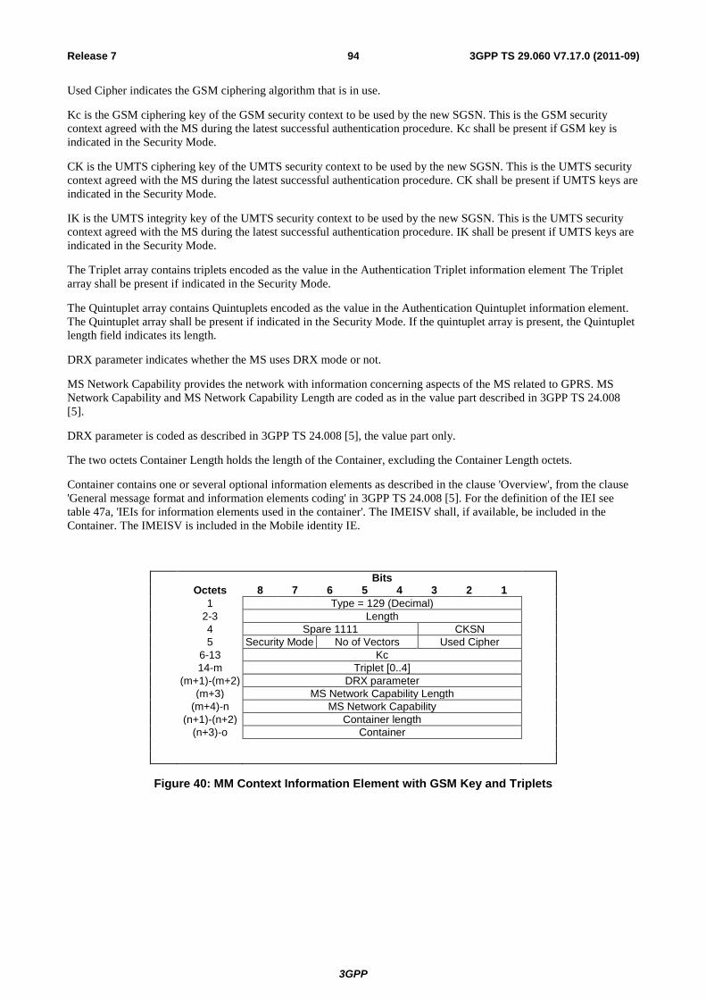
3GPP
3GPP TS 29.060 V7.17.0 (2011-09) 94 Release 7
Used Cipher indicates the GSM ciphering algorithm that is in use.
Kc is the GSM ciphering key of the GSM security context to be used by the new SGSN. This is the GSM security
context agreed with the MS during the latest successful authentication procedure. Kc shall be present if GSM key is
indicated in the Security Mode.
CK is the UMTS ciphering key of the UMTS security context to be used by the new SGSN. This is the UMTS security
context agreed with the MS during the latest successful authentication procedure. CK shall be present if UMTS keys are
indicated in the Security Mode.
IK is the UMTS integrity key of the UMTS security context to be used by the new SGSN. This is the UMTS security
context agreed with the MS during the latest successful authentication procedure. IK shall be present if UMTS keys are
indicated in the Security Mode.
The Triplet array contains triplets encoded as the value in the Authentication Triplet information element The Triplet
array shall be present if indicated in the Security Mode.
The Quintuplet array contains Quintuplets encoded as the value in the Authentication Quintuplet information element.
The Quintuplet array shall be present if indicated in the Security Mode. If the quintuplet array is present, the Quintuplet
length field indicates its length.
DRX parameter indicates whether the MS uses DRX mode or not.
MS Network Capability provides the network with information concerning aspects of the MS related to GPRS. MS
Network Capability and MS Network Capability Length are coded as in the value part described in 3GPP TS 24.008
[5].
DRX parameter is coded as described in 3GPP TS 24.008 [5], the value part only.
The two octets Container Length holds the length of the Container, excluding the Container Length octets.
Container contains one or several optional information elements as described in the clause 'Overview', from the clause
'General message format and information elements coding' in 3GPP TS 24.008 [5]. For the definition of the IEI see
table 47a, 'IEIs for information elements used in the container'. The IMEISV shall, if available, be included in the
Container. The IMEISV is included in the Mobile identity IE.
Bits Octets 8 7 6 5 4 3 2 1
1 Type = 129 (Decimal)
2-3 Length
4 Spare 1111 CKSN
5 Security Mode No of Vectors Used Cipher
6-13 Kc
14-m Triplet [0..4]
(m+1)-(m+2) DRX parameter
(m+3) MS Network Capability Length
(m+4)-n MS Network Capability
(n+1)-(n+2) Container length
(n+3)-o Container
Figure 40: MM Context Information Element with GSM Key and Triplets
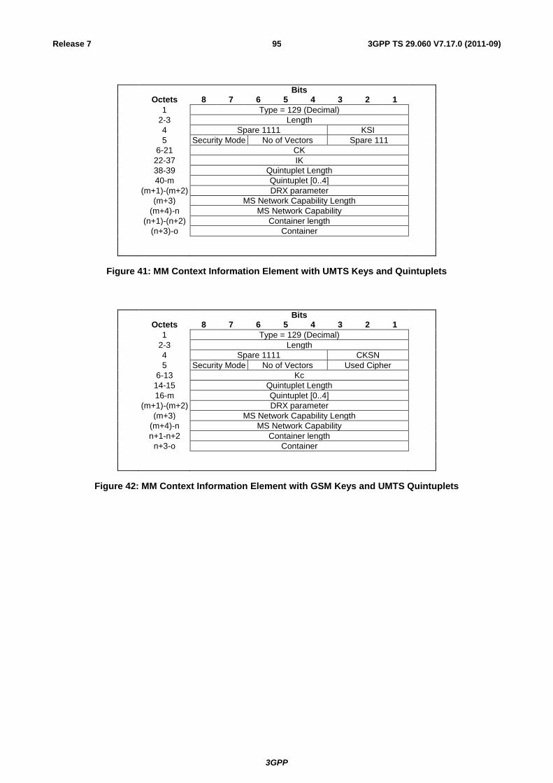
3GPP
3GPP TS 29.060 V7.17.0 (2011-09) 95 Release 7
Bits
Octets 8 7 6 5 4 3 2 1
1 Type = 129 (Decimal)
2-3 Length
4 Spare 1111 KSI
5 Security Mode No of Vectors Spare 111
6-21 CK
22-37 IK
38-39 Quintuplet Length
40-m Quintuplet [0..4]
(m+1)-(m+2) DRX parameter
(m+3) MS Network Capability Length
(m+4)-n MS Network Capability
(n+1)-(n+2) Container length
(n+3)-o Container
Figure 41: MM Context Information Element with UMTS Keys and Quintuplets
Bits Octets 8 7 6 5 4 3 2 1
1 Type = 129 (Decimal)
2-3 Length
4 Spare 1111 CKSN
5 Security Mode No of Vectors Used Cipher
6-13 Kc
14-15 Quintuplet Length
16-m Quintuplet [0..4]
(m+1)-(m+2) DRX parameter
(m+3) MS Network Capability Length
(m+4)-n MS Network Capability
n+1-n+2 Container length
n+3-o Container
Figure 42: MM Context Information Element with GSM Keys and UMTS Quintuplets
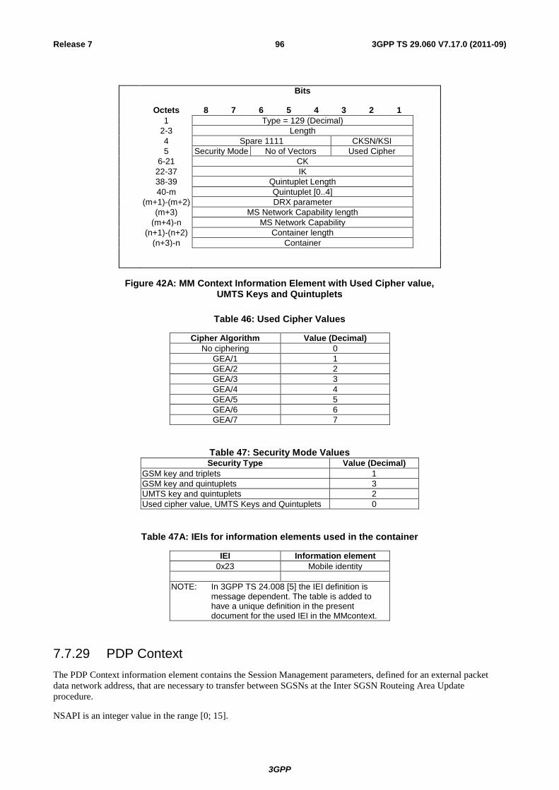
3GPP
3GPP TS 29.060 V7.17.0 (2011-09) 96 Release 7
Bits
Octets 8 7 6 5 4 3 2 1
1 Type = 129 (Decimal)
2-3 Length
4 Spare 1111 CKSN/KSI
5 Security Mode No of Vectors Used Cipher
6-21 CK
22-37 IK
38-39 Quintuplet Length
40-m Quintuplet [0..4]
(m+1)-(m+2) DRX parameter
(m+3) MS Network Capability length
(m+4)-n MS Network Capability
(n+1)-(n+2) Container length
(n+3)-n Container
Figure 42A: MM Context Information Element with Used Cipher value, UMTS Keys and Quintuplets
Table 46: Used Cipher Values
Cipher Algorithm Value (Decimal)
No ciphering 0
GEA/1 1
GEA/2 2
GEA/3 3
GEA/4 4
GEA/5 5
GEA/6 6
GEA/7 7
Table 47: Security Mode ValuesSecurity Type Value (Decimal)
GSM key and triplets 1
GSM key and quintuplets 3
UMTS key and quintuplets 2
Used cipher value, UMTS Keys and Quintuplets 0
Table 47A: IEIs for information elements used in the container
IEI Information element
0x23 Mobile identity
NOTE: In 3GPP TS 24.008 [5] the IEI definition is message dependent. The table is added to have a unique definition in the present document for the used IEI in the MMcontext.
7.7.29 PDP Context
The PDP Context information element contains the Session Management parameters, defined for an external packet
data network address, that are necessary to transfer between SGSNs at the Inter SGSN Routeing Area Update
procedure.
NSAPI is an integer value in the range [0; 15].

3GPP
3GPP TS 29.060 V7.17.0 (2011-09) 97 Release 7
The NSAPI points out the affected PDP context.
The SAPI indicates the LLC SAPI that is associated with the NSAPI.
The Transaction Identifier is the 4 or 12 bit Transaction Identifier used in the 3GPP TS 24.008 [5] Session Management
messages which control this PDP Context. If the length of the Transaction Identifier is 4 bit, the second octet shall be
set to all zeros. The encoding is defined in 3GPP TS 24.007 [3]. The latest Transaction Identifier sent from SGSN to
MS is stored in the PDP context IE.
NOTE: Bit 5-8 of the first octet in the encoding defined in 3GPP TS 24.007 [3] is mapped into bit 1-4 of the first
octet in this field.
Reordering Required (Order) indicates whether the SGSN shall reorder T-PDUs before delivering the T-PDUs to the
MS. When the Quality of Service Negotiated (QoS Neg) is Release 99, the Reordering Required (Order) shall be
ignored by receiving entity.
The VPLMN Address Allowed (VAA) indicates whether the MS is allowed to use the APN in the domain of the
HPLMN only or additionally the APN in the domain of the VPLMN.
The Activity Status Indicator (ASI) indicates whether there is an active RAB/PFC associated with the PDP Context.
This indicator is of interest when the PDP Context IE is included in a FORWARD RELOCATION REQUEST message
or an inter SGSN RAU (SGSN Context Response) triggered by a Directed Signalling Connection Re-establishment.
NOTE: If the ASI indicates that there is no active RAB/PFC associated with the concerned PDP Context at the
source side, no RAB/PFC needs to be set up on the target side.
The QoS Sub Length, QoS Req Length and QoS Neg Length represent respectively the lengths of the QoS Sub, QoS
Req and QoS Neg fields, excluding the QoS Length octet.
The Quality of Service Subscribed (QoS Sub), Quality of Service Requested (QoS Req) and Quality of Service
Negotiated (QoS Neg) are encoded as described in section 'Quality of Service (QoS) Profile'. Their minimum length is 4
octets; their maximum length may be 255 octets.
The Sequence Number Down is the number of the next T-PDU that shall be sent from the new SGSN to the MS. The
number is associated to the Sequence Number from the GTP Header of an encapsulated T-PDU. The new SGSN shall
ignore Sequence Number Down when the PDP context QoS profile does not require transmission order to be preserved.
In this case the new SGSN shall not include Sequence number field in the G-PDUs of the PDP context.
The Sequence Number Up is the number that new SGSN shall use as the Sequence Number in the GTP Header for the
next encapsulated T-PDU from the MS to the GGSN. The new SGSN shall ignore Sequence Number Up when the PDP
context QoS profile does not require transmission order to be preserved. In this case, the new SGSN shall not include
Sequence number field in the G-PDUs of the PDP context.
The Send N-PDU Number is used only when acknowledged peer-to-peer LLC operation is used for the PDP context.
Send N-PDU Number is the N-PDU number to be assigned by SNDCP to the next down link N-PDU received from the
GGSN. It shall be set to 255 if unacknowledged peer-to-peer LLC operation is used for the PDP context.
The Receive N-PDU Number is used only when acknowledged peer-to-peer LLC operation is used for the PDP context.
The Receive N-PDU Number is the N-PDU number expected by SNDCP from the next up link N-PDU to be received
from the MS. It shall be set to 255 if unacknowledged peer-to-peer LLC operation is used for the PDP context.
The Uplink Tunnel Endpoint Identifier Control Plane is the Tunnel Endpoint Identifier used between the old SGSN and
the GGSN in up link direction for control plane purpose. It shall be used by the new SGSN within the GTP header of
the Update PDP Context Request message.
The GGSN Address for User Traffic and the UplinkTunnel Endpoint Identifier Data I are the GGSN address and the
Tunnel Endpoint Identifier used between the old SGSN and the GGSN in uplink direction for user plane traffic on a
PDP context. They shall be used by the new SGSN to send uplink user plane PDU to the GGSN until new GGSN
address for User Traffic is possibly received from GGSN (in Update PDP Context Response).
The PDP Context Identifier is used to identify a PDP context for the subscriber. The SGSN shall set the value of PDP
Context Identifier to binary (1111 1111) if after inter-SGSN RAU using GTPv0 the new SGSN is not able to assign a
correct PDP Context Identifier to the existing PDP contexts.
3GPP
3GPP TS 29.060 V7.17.0 (2011-09) 98 Release 7
The PDP Type Organisation and PDP Type Number are encoded as in the End User Address information element.
The PDP Address Length represents the length of the PDP Address field, excluding the PDP Address Length octet.
The PDP Address is an octet array with a format dependent on the PDP Type. The PDP Address is encoded as in the
End User Address information element if the PDP Type is IPv4 or IPv6.
The GGSN Address Length represents the length of the GGSN Address field, excluding the GGSN Address Length
octet.
When forwarding the GGSN addresses to another SGSN (in PDP Context IE in Forward Relocation Request or SGSN
Context Response message), the IPv4/IPv6 capable SGSN shall include GGSN addresses according to the IP version
capability of the receiving SGSN. Determining the Capability of the receiving SGSN is implementation dependent.
The old SGSN includes the GGSN Address for control plane that it has received from GGSN at PDP context activation
or update. If the new SGSN is IPv6 capable and the old SGSN has IPv6 control plane address of the GGSN available,
the old IPv4/IPv6 capable SGSN includes the IPv6 GGSN control plane address in the field GGSN Address for control
plane. If the new SGSN is IPv4 only capable or the old SGSN does not have any IPv6 GGSN address for control plane,
the old SGSN includes the IPv4 GGSN Address in the field GGSN Address for control plane.
The use of Ipv6 addressing in pre-Release 5 nodes can cause interoperability problems and as such the use of IPv6 GSN
addressing is not recommended in pre-Release 5.
The APN is the Access Point Name in use in the old SGSN. This APN field shall be composed of the APN Network
Identifier part and the APN Operator Identifier part.
The spare bits x indicate unused bits that shall be set to 0 by the sending side and which shall not be evaluated by the
receiving side.
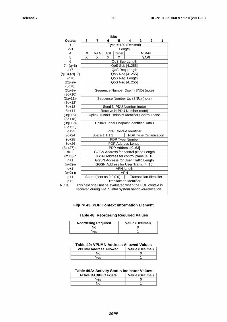
3GPP
3GPP TS 29.060 V7.17.0 (2011-09) 99 Release 7
Bits Octets 8 7 6 5 4 3 2 1
1 Type = 130 (Decimal)
2-3 Length
4 X VAA ASI Order NSAPI
5 X X X X SAPI
6 QoS Sub Length
7 - (q+6) QoS Sub [4..255]
q+7 QoS Req Length
(q+8)-(2q+7) QoS Req [4..255]
2q+8 QoS Neg. Length
(2q+9)-(3q+8)
QoS Neg [4..255]
(3q+9)-(3q+10)
Sequence Number Down (SND) (note)
(3q+11)-(3q+12)
Sequence Number Up (SNU) (note)
3q+13 Send N-PDU Number (note)
3q+14 Receive N-PDU Number (note)
(3q+15)-(3q+18)
Uplink Tunnel Endpoint Identifier Control Plane
(3q+19)-(3q+22)
UplinkTunnel Endpoint Identifier Data I
3q+23 PDP Context Identifier
3q+24 Spare 1 1 1 1 PDP Type Organisation
3q+25 PDP Type Number
3q+26 PDP Address Length
(3q+27)-m PDP Address [0..63]
m+1 GGSN Address for control plane Length
(m+2)-n GGSN Address for control plane [4..16]
n+1 GGSN Address for User Traffic Length
(n+2)-o GGSN Address for User Traffic [4..16]
o+1 APN length
(o+2)-p APN
p+1 Spare (sent as 0 0 0 0) Transaction Identifier
p+2 Transaction Identifier
NOTE: This field shall not be evaluated when the PDP context is received during UMTS intra system handover/relocation.
Figure 43: PDP Context Information Element
Table 48: Reordering Required Values
Reordering Required Value (Decimal)
No 0
Yes 1
Table 49: VPLMN Address Allowed ValuesVPLMN Address Allowed Value (Decimal)
No 0
Yes 1
Table 49A: Activity Status Indicator ValuesActive RAB/PFC exists Value (Decimal)
Yes 0
No 1

3GPP
3GPP TS 29.060 V7.17.0 (2011-09) 100 Release 7
7.7.30 Access Point Name
The Access Point Name is sent by the SGSN or by GGSN as defined in 3GPP TS 23.060 [4].
The Access Point Name contains a logical name (see 3GPP TS 23.060 [4]). It is coded as in the value part defined in
3GPP TS 24.008 [5] (i.e. the 3GPP TS 24.008 [5] IEI and 3GPP TS 24.008 [5] octet length indicator are not included).
Length
Type = 131 (Decimal)
8 7 6 4 3 2 15
Bits
Octets
2-3
1
APN value4-n
Figure 44: Access Point Name Information Element
7.7.31 Protocol Configuration Options
The Protocol Configuration Options contains external network protocol options that may be necessary to transfer
between the GGSN and the MS. The content and the coding of the Protocol Configuration are defined in octet 3-z of the
Protocol Configuration Options in3GPP TS 24.008 [5].
Type = 132 (Decimal)
Length
8 7 6 4 3 2 15
Bits
Octets
2-3
1
4-n Protocol Configuration
Figure 45: Protocol Configuration Options Information Element
7.7.32 GSN Address
The GSN Address information element contains the address of a GSN as defined in 3GPP TS 23.003 [2]. The Address
Type and Address Length fields from 3GPP TS 23.003 [2] are not included in the GSN Address field.
Type = 133 (Decimal)
Length
8 7 6 4 3 2 15
Bits
Octets
2-3
1
GSN Address4-n
Figure 46: GSN Address Information Element
7.7.33 MS International PSTN/ISDN Number (MSISDN)
The MS international ISDN numbers are allocated from the ITU-T Recommendation E.164 numbering plan, see
3GPP TS 23.003 [2]. The MSISDN is coded according to the contents of ISDN-AddressString data type defined in
3GPP TS 29.002 [6]. The MSISDN shall be in international format and the "nature of address indicator" shall indicate
"international number".
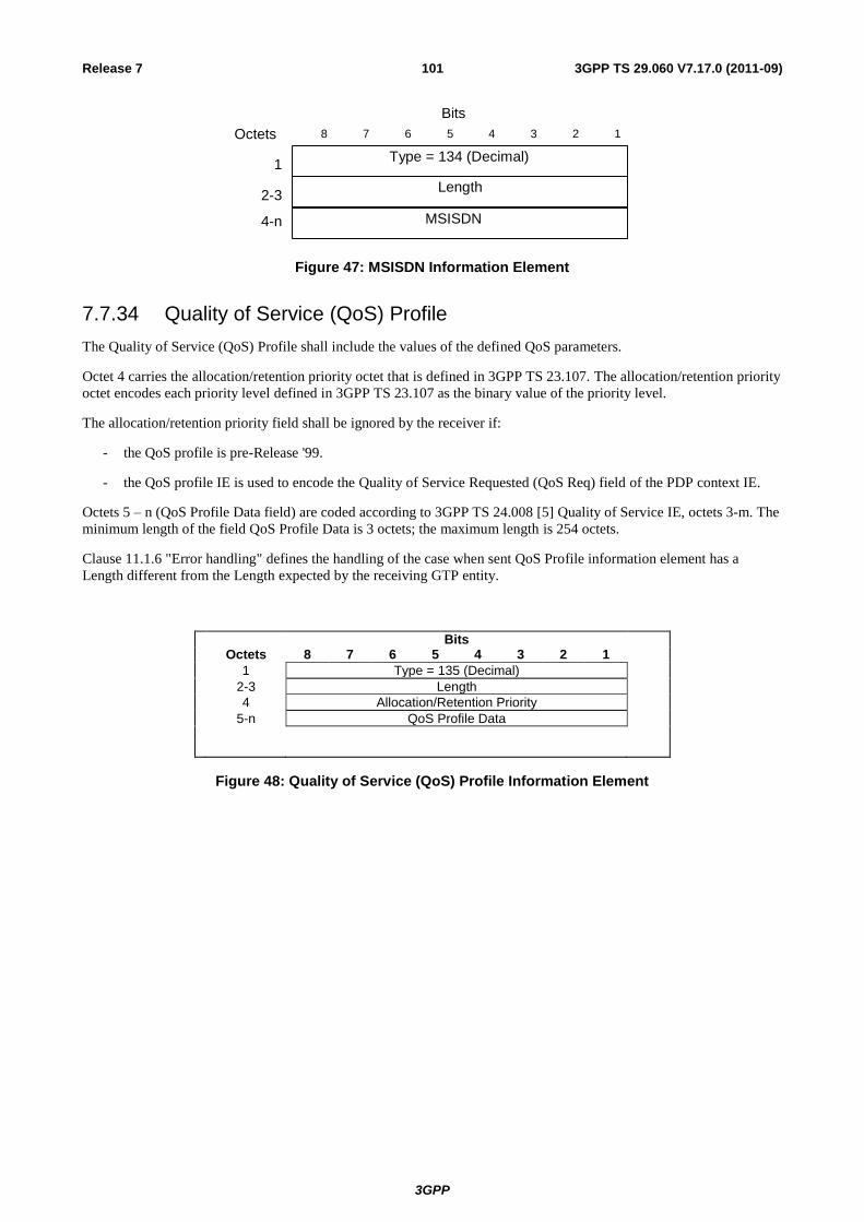
3GPP
3GPP TS 29.060 V7.17.0 (2011-09) 101 Release 7
Length
Type = 134 (Decimal)
8 7 6 4 3 2 1 5
Bits
Octets
2-3
1
MSISDN 4-n
Figure 47: MSISDN Information Element
7.7.34 Quality of Service (QoS) Profile
The Quality of Service (QoS) Profile shall include the values of the defined QoS parameters.
Octet 4 carries the allocation/retention priority octet that is defined in 3GPP TS 23.107. The allocation/retention priority
octet encodes each priority level defined in 3GPP TS 23.107 as the binary value of the priority level.
The allocation/retention priority field shall be ignored by the receiver if:
- the QoS profile is pre-Release '99.
- the QoS profile IE is used to encode the Quality of Service Requested (QoS Req) field of the PDP context IE.
Octets 5 – n (QoS Profile Data field) are coded according to 3GPP TS 24.008 [5] Quality of Service IE, octets 3-m. The
minimum length of the field QoS Profile Data is 3 octets; the maximum length is 254 octets.
Clause 11.1.6 "Error handling" defines the handling of the case when sent QoS Profile information element has a
Length different from the Length expected by the receiving GTP entity.
Bits Octets 8 7 6 5 4 3 2 1
1 Type = 135 (Decimal)
2-3 Length
4 Allocation/Retention Priority
5-n QoS Profile Data
Figure 48: Quality of Service (QoS) Profile Information Element
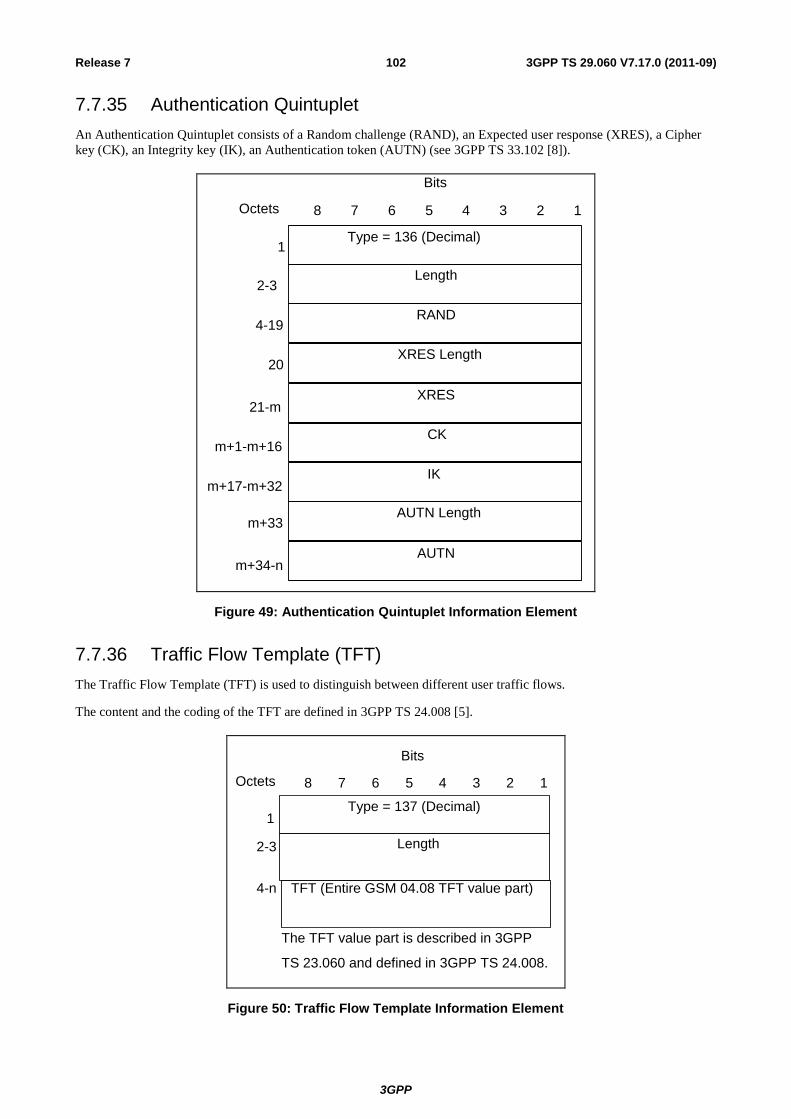
3GPP
3GPP TS 29.060 V7.17.0 (2011-09) 102 Release 7
7.7.35 Authentication Quintuplet
An Authentication Quintuplet consists of a Random challenge (RAND), an Expected user response (XRES), a Cipher
key (CK), an Integrity key (IK), an Authentication token (AUTN) (see 3GPP TS 33.102 [8]).
Type = 136 (Decimal)
RAND
8 7 6 4 3 2 1 5
Bits
Octets
4-19
1
XRES
CK
21-m
m+1-m+16
Length 2-3
XRES Length 20
IK m+17-m+32
AUTN m+34-n
AUTN Length m+33
Figure 49: Authentication Quintuplet Information Element
7.7.36 Traffic Flow Template (TFT)
The Traffic Flow Template (TFT) is used to distinguish between different user traffic flows.
The content and the coding of the TFT are defined in 3GPP TS 24.008 [5].
Length
Type = 137 (Decimal)
8 7 6 4 3 2 1 5
Bits
Octets
4-n
1
The TFT value part is described in 3GPP
TS 23.060 and defined in 3GPP TS 24.008.
TFT (Entire GSM 04.08 TFT value part)
2-3
Figure 50: Traffic Flow Template Information Element
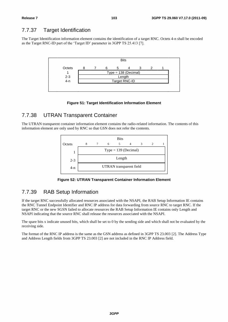
3GPP
3GPP TS 29.060 V7.17.0 (2011-09) 103 Release 7
7.7.37 Target Identification
The Target Identification information element contains the identification of a target RNC. Octets 4-n shall be encoded
as the Target RNC-ID part of the ‘Target ID’ parameter in 3GPP TS 25.413 [7].
Bits
Octets 8 7 6 5 4 3 2 1
1 Type = 138 (Decimal)
2-3 Length
4-n Target RNC-ID
Figure 51: Target Identification Information Element
7.7.38 UTRAN Transparent Container
The UTRAN transparent container information element contains the radio-related information. The contents of this
information element are only used by RNC so that GSN does not refer the contents.
Type = 139 (Decimal)
Length
8 7 6 4 3 2 15
Bits
Octets
2-3
1
UTRAN transparent field4-n
Figure 52: UTRAN Transparent Container Information Element
7.7.39 RAB Setup Information
If the target RNC successfully allocated resources associated with the NSAPI, the RAB Setup Information IE contains
the RNC Tunnel Endpoint Identifier and RNC IP address for data forwarding from source RNC to target RNC. If the
target RNC or the new SGSN failed to allocate resources the RAB Setup Information IE contains only Length and
NSAPI indicating that the source RNC shall release the resources associated with the NSAPI.
The spare bits x indicate unused bits, which shall be set to 0 by the sending side and which shall not be evaluated by the
receiving side.
The format of the RNC IP address is the same as the GSN address as defined in 3GPP TS 23.003 [2]. The Address Type
and Address Length fields from 3GPP TS 23.003 [2] are not included in the RNC IP Address field.
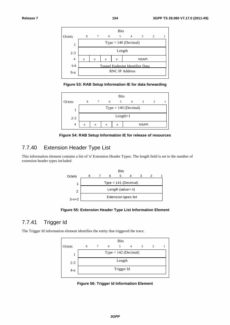
3GPP
3GPP TS 29.060 V7.17.0 (2011-09) 104 Release 7
Type = 140 (Decimal)
Length
8 7 6 4 3 2 15
Bits
Octets
2-3
1
RNC IP Address9-n
5-8
4 x xx
Tunnel Endpoint Identifier Data
NSAPIx
Figure 53: RAB Setup Information IE for data forwarding
Type = 140 (Decimal)
Length=1
8 7 6 4 3 2 15
Bits
Octets
2-3
1
4 x xx NSAPIx
Figure 54: RAB Setup Information IE for release of resources
7.7.40 Extension Header Type List
This information element contains a list of 'n' Extension Header Types. The length field is set to the number of
extension header types included.
Type = 141 (Decimal)
Length (value= n)
8 7 6 4 3 2 1 5 Bits
Octets
2
1
3-n+2 Extension types list
Figure 55: Extension Header Type List Information Element
7.7.41 Trigger Id
The Trigger Id information element identifies the entity that triggered the trace.
Type = 142 (Decimal)
Length
8 7 6 4 3 2 15
Bits
Octets
2-3
1
Trigger Id4-n
Figure 56: Trigger Id Information Element
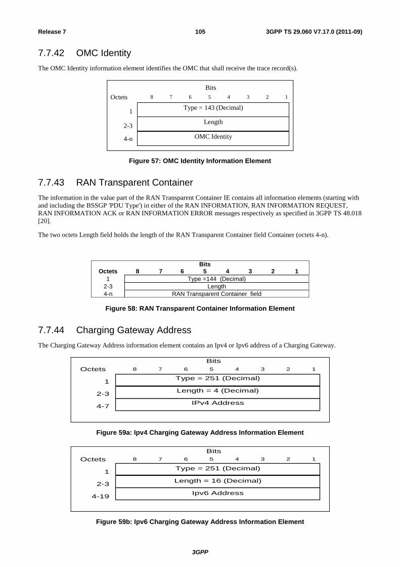
3GPP
3GPP TS 29.060 V7.17.0 (2011-09) 105 Release 7
7.7.42 OMC Identity
The OMC Identity information element identifies the OMC that shall receive the trace record(s).
Type = 143 (Decimal)
Length
8 7 6 4 3 2 15
Bits
Octets
2-3
1
OMC Identity4-n
Figure 57: OMC Identity Information Element
7.7.43 RAN Transparent Container
The information in the value part of the RAN Transparent Container IE contains all information elements (starting with
and including the BSSGP 'PDU Type') in either of the RAN INFORMATION, RAN INFORMATION REQUEST,
RAN INFORMATION ACK or RAN INFORMATION ERROR messages respectively as specified in 3GPP TS 48.018
[20].
The two octets Length field holds the length of the RAN Transparent Container field Container (octets 4-n).
Bits Octets 8 7 6 5 4 3 2 1
1 Type =144 (Decimal)
2-3 Length
4-n RAN Transparent Container field
Figure 58: RAN Transparent Container Information Element
7.7.44 Charging Gateway Address
The Charging Gateway Address information element contains an Ipv4 or Ipv6 address of a Charging Gateway.
Type = 251 (Decimal)
Length = 4 (Decimal)
8 7 6 4 3 2 1 5
Bits
Octets
4-7
2-3
1
IPv4 Address
Figure 59a: Ipv4 Charging Gateway Address Information Element
Type = 251 (Decimal)
Length = 16 (Decimal)
8 7 6 4 3 2 15
Bits
Octets
4-19
2-3
1
Ipv6 Address
Figure 59b: Ipv6 Charging Gateway Address Information Element
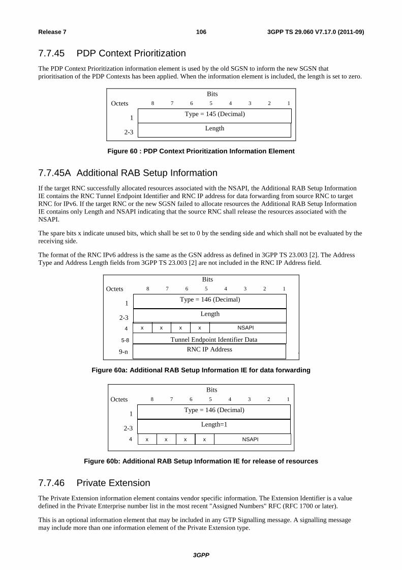
3GPP
3GPP TS 29.060 V7.17.0 (2011-09) 106 Release 7
7.7.45 PDP Context Prioritization
The PDP Context Prioritization information element is used by the old SGSN to inform the new SGSN that
prioritisation of the PDP Contexts has been applied. When the information element is included, the length is set to zero.
Type = 145 (Decimal)
8 7 6 4 3 2 1 5
Bits
Octets
2-3
1
Length
Figure 60 : PDP Context Prioritization Information Element
7.7.45A Additional RAB Setup Information
If the target RNC successfully allocated resources associated with the NSAPI, the Additional RAB Setup Information
IE contains the RNC Tunnel Endpoint Identifier and RNC IP address for data forwarding from source RNC to target
RNC for IPv6. If the target RNC or the new SGSN failed to allocate resources the Additional RAB Setup Information
IE contains only Length and NSAPI indicating that the source RNC shall release the resources associated with the
NSAPI.
The spare bits x indicate unused bits, which shall be set to 0 by the sending side and which shall not be evaluated by the
receiving side.
The format of the RNC IPv6 address is the same as the GSN address as defined in 3GPP TS 23.003 [2]. The Address
Type and Address Length fields from 3GPP TS 23.003 [2] are not included in the RNC IP Address field.
Type = 146 (Decimal)
Length
8 7 6 4 3 2 1 5
Bits
Octets
2-3
1
RNC IP Address 9-n
5-8
4 x x x
Tunnel Endpoint Identifier Data
NSAPI x
Figure 60a: Additional RAB Setup Information IE for data forwarding
Type = 146 (Decimal)
Length=1
8 7 6 4 3 2 1 5
Bits
Octets
2-3
1
4 x x x NSAPI x
Figure 60b: Additional RAB Setup Information IE for release of resources
7.7.46 Private Extension
The Private Extension information element contains vendor specific information. The Extension Identifier is a value
defined in the Private Enterprise number list in the most recent "Assigned Numbers" RFC (RFC 1700 or later).
This is an optional information element that may be included in any GTP Signalling message. A signalling message
may include more than one information element of the Private Extension type.
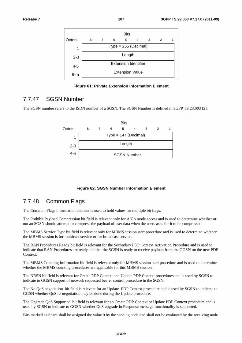
3GPP
3GPP TS 29.060 V7.17.0 (2011-09) 107 Release 7
Type = 255 (Decimal)
Length
8 7 6 4 3 2 15
Bits
Octets
2-3
1
4-5Extension Identifier
6-mExtension Value
Figure 61: Private Extension Information Element
7.7.47 SGSN Number
The SGSN number refers to the ISDN number of a SGSN. The SGSN Number is defined in 3GPP TS 23.003 [2].
Length
Type = 147 (Decimal)
8 7 6 4 3 2 1 5
Bits
Octets
2-3
1
SGSN Number 4-n
Figure 62: SGSN Number Information Element
7.7.48 Common Flags
The Common Flags information element is used to hold values for multiple bit flags.
The Prohibit Payload Compression bit field is relevant only for A/Gb mode access and is used to determine whether or
not an SGSN should attempt to compress the payload of user data when the users asks for it to be compressed.
The MBMS Service Type bit field is relevant only for MBMS session start procedure and is used to determine whether
the MBMS session is for multicast service or for broadcast service.
The RAN Procedures Ready bit field is relevant for the Secondary PDP Context Activation Procedure and is used to
indicate that RAN Procedures are ready and that the SGSN is ready to receive payload from the GGSN on the new PDP
Context.
The MBMS Counting Information bit field is relevant only for MBMS session start procedure and is used to determine
whether the MBMS counting procedures are applicable for this MBMS session.
The NRSN bit field is relevant for Create PDP Context and Update PDP Context procedures and is used by SGSN to
indicate to GGSN support of network requested bearer control procedure in the SGSN.
The No QoS negotiation bit field is relevant for an Update PDP Context procedure and is used by SGSN to indicate to
GGSN whether QoS re-negotiation may be done during the Update procedure.
The Upgrade QoS Supported bit field is relevant for an Create PDP Context or Update PDP Context procedure and is
used by SGSN to indicate to GGSN whether QoS upgrade in Response message functionality is supported.
Bits marked as Spare shall be assigned the value 0 by the sending node and shall not be evaluated by the receiving node.
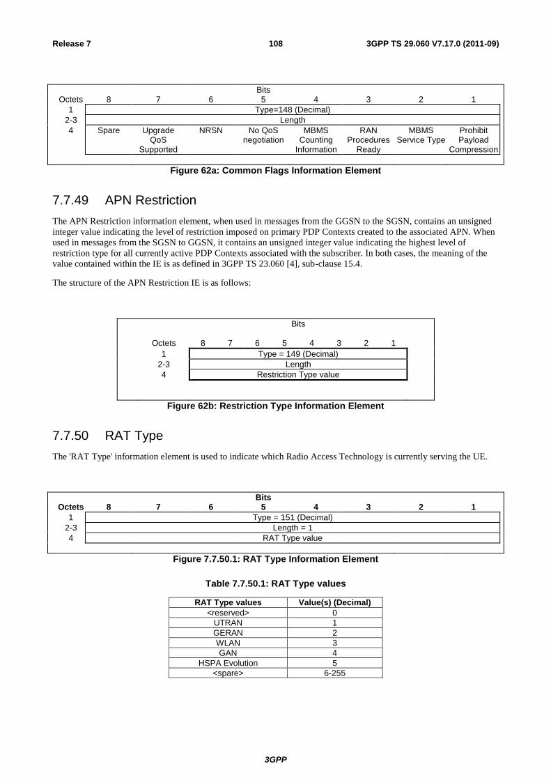
3GPP
3GPP TS 29.060 V7.17.0 (2011-09) 108 Release 7
Bits Octets 8 7 6 5 4 3 2 1
1 Type=148 (Decimal)
2-3 Length
4 Spare Upgrade QoS
Supported
NRSN No QoS negotiation
MBMS Counting
Information
RAN Procedures
Ready
MBMS Service Type
Prohibit Payload
Compression
Figure 62a: Common Flags Information Element
7.7.49 APN Restriction
The APN Restriction information element, when used in messages from the GGSN to the SGSN, contains an unsigned
integer value indicating the level of restriction imposed on primary PDP Contexts created to the associated APN. When
used in messages from the SGSN to GGSN, it contains an unsigned integer value indicating the highest level of
restriction type for all currently active PDP Contexts associated with the subscriber. In both cases, the meaning of the
value contained within the IE is as defined in 3GPP TS 23.060 [4], sub-clause 15.4.
The structure of the APN Restriction IE is as follows:
Bits
Octets 8 7 6 5 4 3 2 1
1 Type = 149 (Decimal)
2-3 Length
4 Restriction Type value
Figure 62b: Restriction Type Information Element
7.7.50 RAT Type
The 'RAT Type' information element is used to indicate which Radio Access Technology is currently serving the UE.
Bits
Octets 8 7 6 5 4 3 2 1
1 Type = 151 (Decimal)
2-3 Length = 1
4 RAT Type value
Figure 7.7.50.1: RAT Type Information Element
Table 7.7.50.1: RAT Type values
RAT Type values Value(s) (Decimal)
<reserved> 0
UTRAN 1
GERAN 2
WLAN 3
GAN 4
HSPA Evolution 5
<spare> 6-255
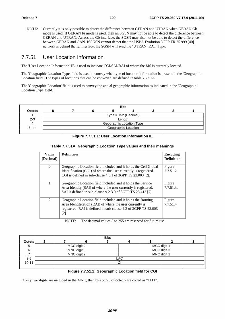
3GPP
3GPP TS 29.060 V7.17.0 (2011-09) 109 Release 7
NOTE: Currently it is only possible to detect the difference between GERAN and UTRAN when GERAN Gb
mode is used. If GERAN Iu mode is used, then an SGSN may not be able to detect the difference between
GERAN and UTRAN. Across the Gb interface, the SGSN may also not be able to detect the difference
between GERAN and GAN. If SGSN cannot detect that the HSPA Evolution 3GPP TR 25.999 [40]
network is behind the Iu interface, the SGSN will send the ‘UTRAN’ RAT Type.
7.7.51 User Location Information
The 'User Location Information' IE is used to indicate CGI/SAI/RAI of where the MS is currently located.
The 'Geographic Location Type' field is used to convey what type of location information is present in the 'Geographic
Location field'. The types of locations that can be conveyed are defined in table 7.7.51A.
The 'Geographic Location' field is used to convey the actual geographic information as indicated in the 'Geographic
Location Type' field.
Bits Octets 8 7 6 5 4 3 2 1
1 Type = 152 (Decimal)
2-3 Length
4 Geographic Location Type
5 - m Geographic Location
Figure 7.7.51.1: User Location Information IE
Table 7.7.51A: Geographic Location Type values and their meanings
Value
(Decimal)
Definition Encoding
Definition
0 Geographic Location field included and it holds the Cell Global
Identification (CGI) of where the user currently is registered.
CGI is defined in sub-clause 4.3.1 of 3GPP TS 23.003 [2].
Figure
7.7.51.2.
1 Geographic Location field included and it holds the Service
Area Identity (SAI) of where the user currently is registered.
SAI is defined in sub-clause 9.2.3.9 of 3GPP TS 25.413 [7].
Figure
7.7.51.3.
2 Geographic Location field included and it holds the Routing
Area Identification (RAI) of where the user currently is
registered. RAI is defined in sub-clause 4.2 of 3GPP TS 23.003
[2].
Figure
7.7.51.4
NOTE: The decimal values 3 to 255 are reserved for future use.
Bits
Octets 8 7 6 5 4 3 2 1
5 MCC digit 2 MCC digit 1
6 MNC digit 3 MCC digit 3
7 MNC digit 2 MNC digit 1
8-9 LAC
10-11 CI
Figure 7.7.51.2: Geographic Location field for CGI
If only two digits are included in the MNC, then bits 5 to 8 of octet 6 are coded as "1111".
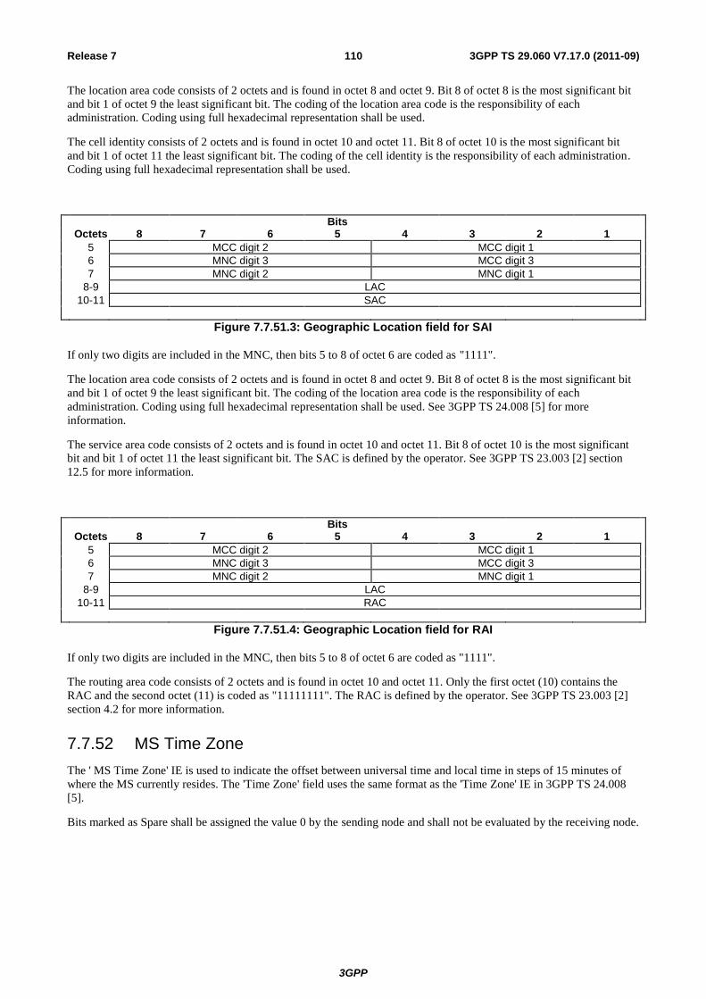
3GPP
3GPP TS 29.060 V7.17.0 (2011-09) 110 Release 7
The location area code consists of 2 octets and is found in octet 8 and octet 9. Bit 8 of octet 8 is the most significant bit
and bit 1 of octet 9 the least significant bit. The coding of the location area code is the responsibility of each
administration. Coding using full hexadecimal representation shall be used.
The cell identity consists of 2 octets and is found in octet 10 and octet 11. Bit 8 of octet 10 is the most significant bit
and bit 1 of octet 11 the least significant bit. The coding of the cell identity is the responsibility of each administration.
Coding using full hexadecimal representation shall be used.
Bits
Octets 8 7 6 5 4 3 2 1
5 MCC digit 2 MCC digit 1
6 MNC digit 3 MCC digit 3
7 MNC digit 2 MNC digit 1
8-9 LAC
10-11 SAC
Figure 7.7.51.3: Geographic Location field for SAI
If only two digits are included in the MNC, then bits 5 to 8 of octet 6 are coded as "1111".
The location area code consists of 2 octets and is found in octet 8 and octet 9. Bit 8 of octet 8 is the most significant bit
and bit 1 of octet 9 the least significant bit. The coding of the location area code is the responsibility of each
administration. Coding using full hexadecimal representation shall be used. See 3GPP TS 24.008 [5] for more
information.
The service area code consists of 2 octets and is found in octet 10 and octet 11. Bit 8 of octet 10 is the most significant
bit and bit 1 of octet 11 the least significant bit. The SAC is defined by the operator. See 3GPP TS 23.003 [2] section
12.5 for more information.
Bits
Octets 8 7 6 5 4 3 2 1
5 MCC digit 2 MCC digit 1
6 MNC digit 3 MCC digit 3
7 MNC digit 2 MNC digit 1
8-9 LAC
10-11 RAC
Figure 7.7.51.4: Geographic Location field for RAI
If only two digits are included in the MNC, then bits 5 to 8 of octet 6 are coded as "1111".
The routing area code consists of 2 octets and is found in octet 10 and octet 11. Only the first octet (10) contains the
RAC and the second octet (11) is coded as "11111111". The RAC is defined by the operator. See 3GPP TS 23.003 [2]
section 4.2 for more information.
7.7.52 MS Time Zone
The ' MS Time Zone' IE is used to indicate the offset between universal time and local time in steps of 15 minutes of
where the MS currently resides. The 'Time Zone' field uses the same format as the 'Time Zone' IE in 3GPP TS 24.008
[5].
Bits marked as Spare shall be assigned the value 0 by the sending node and shall not be evaluated by the receiving node.
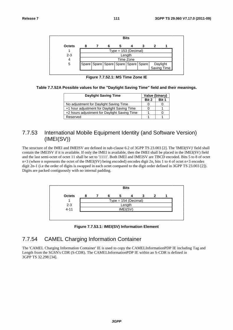
3GPP
3GPP TS 29.060 V7.17.0 (2011-09) 111 Release 7
Bits
Octets 8 7 6 5 4 3 2 1
1 Type = 153 (Decimal)
2-3 Length
4 Time Zone
5 Spare Spare Spare Spare Spare Spare Daylight Saving Time
Figure 7.7.52.1: MS Time Zone IE
Table 7.7.52A Possible values for the "Daylight Saving Time" field and their meanings.
Daylight Saving Time Value (binary)
Bit 2 Bit 1
No adjustment for Daylight Saving Time 0 0
+1 hour adjustment for Daylight Saving Time 0 1
+2 hours adjustment for Daylight Saving Time 1 0
Reserved 1 1
7.7.53 International Mobile Equipment Identity (and Software Version) (IMEI(SV))
The structure of the IMEI and IMEISV are defined in sub-clause 6.2 of 3GPP TS 23.003 [2]. The 'IMEI(SV)' field shall
contain the IMEISV if it is available. If only the IMEI is available, then the IMEI shall be placed in the IMEI(SV) field
and the last semi-octet of octet 11 shall be set to '1111'. Both IMEI and IMEISV are TBCD encoded. Bits 5 to 8 of octet
n+3 (where n represents the octet of the IMEI(SV) being encoded) encodes digit 2n, bits 1 to 4 of octet n+3 encodes
digit 2n-1 (i.e the order of digits is swapped in each octet compared to the digit order defined in 3GPP TS 23.003 [2]).
Digits are packed contiguously with no internal padding.
Bits
Octets 8 7 6 5 4 3 2 1
1 Type = 154 (Decimal)
2-3 Length
4-11 IMEI(SV)
Figure 7.7.53.1: IMEI(SV) Information Element
7.7.54 CAMEL Charging Information Container
The 'CAMEL Charging Information Container' IE is used to copy the CAMELInformationPDP IE including Tag and
Length from the SGSN's CDR (S-CDR). The CAMELInformationPDP IE within an S-CDR is defined in
3GPP TS 32.298 [34].
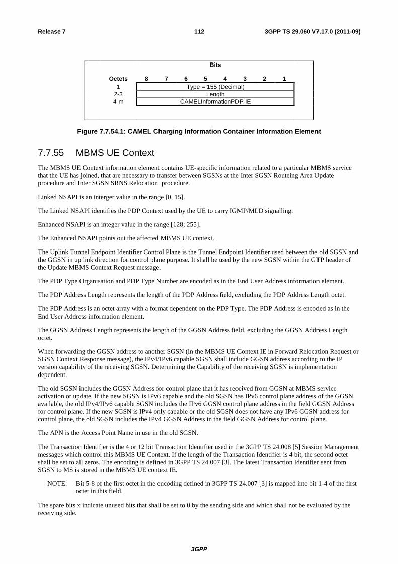
3GPP
3GPP TS 29.060 V7.17.0 (2011-09) 112 Release 7
Bits
Octets 8 7 6 5 4 3 2 1
1 Type = 155 (Decimal)
2-3 Length
4-m CAMELInformationPDP IE
Figure 7.7.54.1: CAMEL Charging Information Container Information Element
7.7.55 MBMS UE Context
The MBMS UE Context information element contains UE-specific information related to a particular MBMS service
that the UE has joined, that are necessary to transfer between SGSNs at the Inter SGSN Routeing Area Update
procedure and Inter SGSN SRNS Relocation procedure.
Linked NSAPI is an interger value in the range [0, 15].
The Linked NSAPI identifies the PDP Context used by the UE to carry IGMP/MLD signalling.
Enhanced NSAPI is an integer value in the range [128; 255].
The Enhanced NSAPI points out the affected MBMS UE context.
The Uplink Tunnel Endpoint Identifier Control Plane is the Tunnel Endpoint Identifier used between the old SGSN and
the GGSN in up link direction for control plane purpose. It shall be used by the new SGSN within the GTP header of
the Update MBMS Context Request message.
The PDP Type Organisation and PDP Type Number are encoded as in the End User Address information element.
The PDP Address Length represents the length of the PDP Address field, excluding the PDP Address Length octet.
The PDP Address is an octet array with a format dependent on the PDP Type. The PDP Address is encoded as in the
End User Address information element.
The GGSN Address Length represents the length of the GGSN Address field, excluding the GGSN Address Length
octet.
When forwarding the GGSN address to another SGSN (in the MBMS UE Context IE in Forward Relocation Request or
SGSN Context Response message), the IPv4/IPv6 capable SGSN shall include GGSN address according to the IP
version capability of the receiving SGSN. Determining the Capability of the receiving SGSN is implementation
dependent.
The old SGSN includes the GGSN Address for control plane that it has received from GGSN at MBMS service
activation or update. If the new SGSN is IPv6 capable and the old SGSN has IPv6 control plane address of the GGSN
available, the old IPv4/IPv6 capable SGSN includes the IPv6 GGSN control plane address in the field GGSN Address
for control plane. If the new SGSN is IPv4 only capable or the old SGSN does not have any IPv6 GGSN address for
control plane, the old SGSN includes the IPv4 GGSN Address in the field GGSN Address for control plane.
The APN is the Access Point Name in use in the old SGSN.
The Transaction Identifier is the 4 or 12 bit Transaction Identifier used in the 3GPP TS 24.008 [5] Session Management
messages which control this MBMS UE Context. If the length of the Transaction Identifier is 4 bit, the second octet
shall be set to all zeros. The encoding is defined in 3GPP TS 24.007 [3]. The latest Transaction Identifier sent from
SGSN to MS is stored in the MBMS UE context IE.
NOTE: Bit 5-8 of the first octet in the encoding defined in 3GPP TS 24.007 [3] is mapped into bit 1-4 of the first
octet in this field.
The spare bits x indicate unused bits that shall be set to 0 by the sending side and which shall not be evaluated by the
receiving side.

3GPP
3GPP TS 29.060 V7.17.0 (2011-09) 113 Release 7
Bits Octets 8 7 6 5 4 3 2 1
1 Type = 156 (Decimal)
2-3 Length
4 Linked NSAPI Spare (sent as 0 0 0 0)
5-8 Uplink Tunnel Endpoint Identifier Control Plane
167 Enhanced NSAPI
9 Spare 1 1 1 1 PDP Type Organisation
10 PDP Type Number
11 PDP Address Length
12-m PDP Address [0..63]
m+1 GGSN Address for control plane Length
(m+2)-n GGSN Address for control plane [4..16]
n+1 APN length
(n+2)-o APN
(o+1) Spare (sent as 0 0 0 0) Transaction Identifier
o+2 Transaction Identifier
Figure 7.7.55.1: MBMS UE Context Information Element
7.7.56 Temporary Mobile Group Identity
The Temporary Mobile Group Identity (TMGI) information element contains a TMGI allocated by the BM-SC. The
BM-SC always includes the MCC and MNC when allocating the TMGI, see 3GPP TS 29.061[27]. The TMGI shall be
coded as the value part defined in 3GPP T S 24.008 [5] (i.e. the IEI and octet length indicator are not included).
Bits
Octets 8 7 6 5 4 3 2 1
1 Type = 157 (Decimal)
2-3 Length
4-9 Temporary Mobile Group Identity
Figure 7.7.56.1: Temporary Mobile Group Identity
7.7.57 RIM Routing Address
Octets 4-n are coded according to 3GPP TS 48.018 [20] RIM Routing Information IE octets 4-n.
Bits
Octets 8 7 6 5 4 3 2 1
1 Type = 158 (Decimal)
2-3 Length
4-n RIM Routing Address
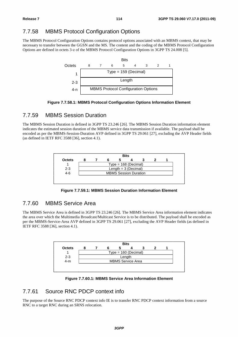
3GPP
3GPP TS 29.060 V7.17.0 (2011-09) 114 Release 7
7.7.58 MBMS Protocol Configuration Options
The MBMS Protocol Configuration Options contains protocol options associated with an MBMS context, that may be
necessary to transfer between the GGSN and the MS. The content and the coding of the MBMS Protocol Configuration
Options are defined in octets 3-z of the MBMS Protocol Configuration Options in 3GPP TS 24.008 [5].
Length
Type = 159 (Decimal)
8 7 6 4 3 2 1 5
Bits
Octets
2-3
1
MBMS Protocol Configuration Options 4-n
Figure 7.7.58.1: MBMS Protocol Configuration Options Information Element
7.7.59 MBMS Session Duration
The MBMS Session Duration is defined in 3GPP TS 23.246 [26]. The MBMS Session Duration information element
indicates the estimated session duration of the MBMS service data transmission if available. The payload shall be
encoded as per the MBMS-Session-Duration AVP defined in 3GPP TS 29.061 [27], excluding the AVP Header fields
(as defined in IETF RFC 3588 [36], section 4.1).
Bits Octets 8 7 6 5 4 3 2 1
1 Type = 168 (Decimal)
2-3 Length = 3 (Decimal)
4-6 MBMS Session Duration
Figure 7.7.59.1: MBMS Session Duration Information Element
7.7.60 MBMS Service Area
The MBMS Service Area is defined in 3GPP TS 23.246 [26]. The MBMS Service Area information element indicates
the area over which the Multimedia Broadcast/Multicast Service is to be distributed. The payload shall be encoded as
per the MBMS-Service-Area AVP defined in 3GPP TS 29.061 [27], excluding the AVP Header fields (as defined in
IETF RFC 3588 [36], section 4.1).
Bits Octets 8 7 6 5 4 3 2 1
1 Type = 160 (Decimal)
2-3 Length
4-m MBMS Service Area
Figure 7.7.60.1: MBMS Service Area Information Element
7.7.61 Source RNC PDCP context info
The purpose of the Source RNC PDCP context info IE is to transfer RNC PDCP context information from a source
RNC to a target RNC during an SRNS relocation.

3GPP
3GPP TS 29.060 V7.17.0 (2011-09) 115 Release 7
This IE is transparent to CN .
Bits
Octets 8 7 6 5 4 3 2 1
1 Type = 161 (Decimal)
2-3 Length
4-n RRC Container
Figure 7.7.61.1: Source RNC PDCP context info Information Element
7.7.62 Additional Trace Info
The additional Trace Info is used to inform the GGSN of the additional trace parameters. An Additional Trace Info
consists of Trace Reference2, Trace Recording Session Reference, triggering events in GGSN, Trace Depth, List of
interfaces to trace in GGSN and a Trace Activity Control. The encoding are defined in 3GPP TS 32.422 [31].
The Trace Activity Control is used to indicate to GGSN whether the Trace is activated or deactivated.
Bits Octets 8 7 6 5 4 3 2 1
1 Type =162 (Decimal)
2-3 Length
4-6 Trace Reference2
7-8 Trace Recording Session Reference
9 Triggering events in GGSN
10 Trace Depth
11 List of interfaces in GGSN
12 Trace Activity Control
Figure 7.7.62.1: Additional Trace Info Information Element
Trace Activity Control Value (Decimal)
Trace Activation 1
Trace Deactivation 0
All other values are reserved
Figure 7.7.62.2: Trace Activity Control Value
7.7.63 Hop Counter
Where Intra Domain Connection of RAN Nodes to Multiple CN Nodes is applied, the Hop Counter may be used to
prevent endless loops when relaying Identification Request messages and SGSN Context Request messages. The
maximum value is operator specific and shall not be lower than 1.
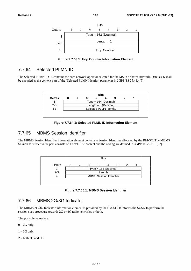
3GPP
3GPP TS 29.060 V7.17.0 (2011-09) 116 Release 7
Length = 1
Type = 163 (Decimal)
8 7 6 4 3 2 1 5
Bits
Octets
2-3
1
Hop Counter 4
Figure 7.7.63.1: Hop Counter Information Element
7.7.64 Selected PLMN ID
The Selected PLMN ID IE contains the core network operator selected for the MS in a shared network. Octets 4-6 shall
be encoded as the content part of the ‘Selected PLMN Identity’ parameter in 3GPP TS 25.413 [7].
Bits Octets 8 7 6 5 4 3 2 1
1 Type = 164 (Decimal)
2-3 Length = 3 (Decimal)
4-6 Selected PLMN Identity
Figure 7.7.64.1: Selected PLMN ID Information Element
7.7.65 MBMS Session Identifier
The MBMS Session Identifier information element contains a Session Identifier allocated by the BM-SC. The MBMS
Session Identifier value part consists of 1 octet. The content and the coding are defined in 3GPP TS 29.061 [27].
Bits
Octets 8 7 6 5 4 3 2 1
1 Type = 165 (Decimal)
2-3 Length
4 MBMS Session Identifier
Figure 7.7.65.1: MBMS Session Identifier
7.7.66 MBMS 2G/3G Indicator
The MBMS 2G/3G Indicator information element is provided by the BM-SC. It informs the SGSN to perform the
session start procedure towards 2G or 3G radio networks, or both.
The possible values are:
0 – 2G only.
1 – 3G only.
2 – both 2G and 3G.
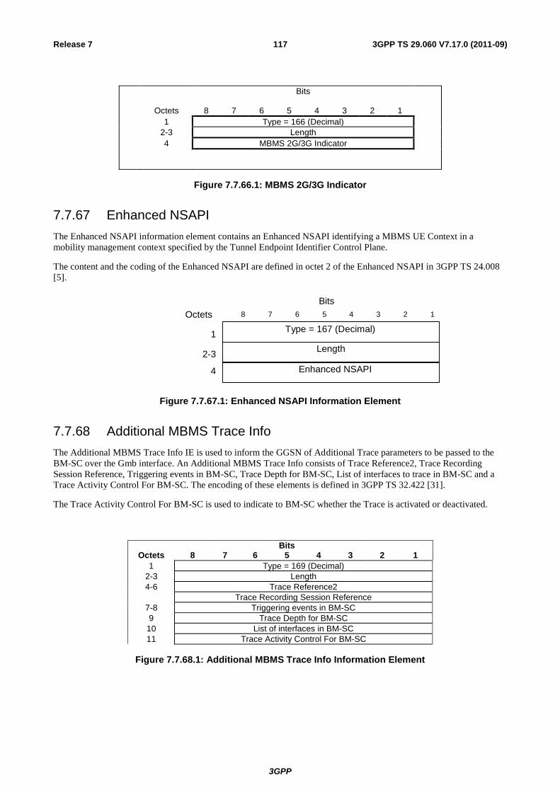
3GPP
3GPP TS 29.060 V7.17.0 (2011-09) 117 Release 7
Bits
Octets 8 7 6 5 4 3 2 1
1 Type = 166 (Decimal)
2-3 Length
4 MBMS 2G/3G Indicator
Figure 7.7.66.1: MBMS 2G/3G Indicator
7.7.67 Enhanced NSAPI
The Enhanced NSAPI information element contains an Enhanced NSAPI identifying a MBMS UE Context in a
mobility management context specified by the Tunnel Endpoint Identifier Control Plane.
The content and the coding of the Enhanced NSAPI are defined in octet 2 of the Enhanced NSAPI in 3GPP TS 24.008
[5].
Length
Type = 167 (Decimal)
8 7 6 4 3 2 1 5
Bits
Octets
2-3
1
Enhanced NSAPI 4
Figure 7.7.67.1: Enhanced NSAPI Information Element
7.7.68 Additional MBMS Trace Info
The Additional MBMS Trace Info IE is used to inform the GGSN of Additional Trace parameters to be passed to the
BM-SC over the Gmb interface. An Additional MBMS Trace Info consists of Trace Reference2, Trace Recording
Session Reference, Triggering events in BM-SC, Trace Depth for BM-SC, List of interfaces to trace in BM-SC and a
Trace Activity Control For BM-SC. The encoding of these elements is defined in 3GPP TS 32.422 [31].
The Trace Activity Control For BM-SC is used to indicate to BM-SC whether the Trace is activated or deactivated.
Bits Octets 8 7 6 5 4 3 2 1
1 Type = 169 (Decimal)
2-3 Length
4-6 Trace Reference2
Trace Recording Session Reference
7-8 Triggering events in BM-SC
9 Trace Depth for BM-SC
10 List of interfaces in BM-SC
11 Trace Activity Control For BM-SC
Figure 7.7.68.1: Additional MBMS Trace Info Information Element
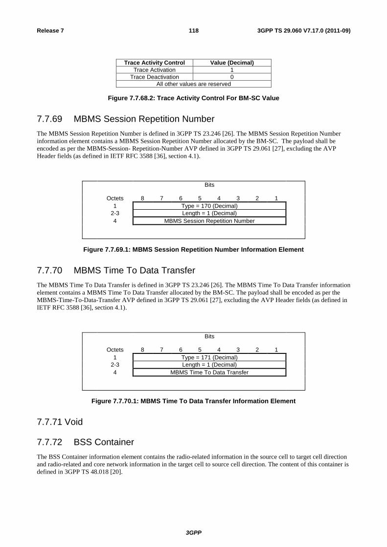
3GPP
3GPP TS 29.060 V7.17.0 (2011-09) 118 Release 7
Trace Activity Control Value (Decimal)
Trace Activation 1
Trace Deactivation 0
All other values are reserved
Figure 7.7.68.2: Trace Activity Control For BM-SC Value
7.7.69 MBMS Session Repetition Number
The MBMS Session Repetition Number is defined in 3GPP TS 23.246 [26]. The MBMS Session Repetition Number
information element contains a MBMS Session Repetition Number allocated by the BM-SC. The payload shall be
encoded as per the MBMS-Session- Repetition-Number AVP defined in 3GPP TS 29.061 [27], excluding the AVP
Header fields (as defined in IETF RFC 3588 [36], section 4.1).
Bits
Octets 8 7 6 5 4 3 2 1
1 Type = 170 (Decimal)
2-3 Length = 1 (Decimal)
4 MBMS Session Repetition Number
Figure 7.7.69.1: MBMS Session Repetition Number Information Element
7.7.70 MBMS Time To Data Transfer
The MBMS Time To Data Transfer is defined in 3GPP TS 23.246 [26]. The MBMS Time To Data Transfer information
element contains a MBMS Time To Data Transfer allocated by the BM-SC. The payload shall be encoded as per the
MBMS-Time-To-Data-Transfer AVP defined in 3GPP TS 29.061 [27], excluding the AVP Header fields (as defined in
IETF RFC 3588 [36], section 4.1).
Bits
Octets 8 7 6 5 4 3 2 1
1 Type = 171 (Decimal)
2-3 Length = 1 (Decimal)
4 MBMS Time To Data Transfer
Figure 7.7.70.1: MBMS Time To Data Transfer Information Element
7.7.71 Void
7.7.72 BSS Container
The BSS Container information element contains the radio-related information in the source cell to target cell direction
and radio-related and core network information in the target cell to source cell direction. The content of this container is
defined in 3GPP TS 48.018 [20].

3GPP
3GPP TS 29.060 V7.17.0 (2011-09) 119 Release 7
Bits Octets 8 7 6 5 4 3 2 1
1 Type = 173 (Decimal)
2-3 Length
4 -n BSS Container
Figure 7.7.72.1: BSS Container Information Element
7.7.73 Cell Identification
The Cell Identification information element contains
for PS handover from A/Gb mode, the identification of a target cell (Target Cell ID) and the identification of
the source cell (Source Cell ID) as defined in 3GPP TS 48.018 [20].
for PS handover from Iu mode, the identification of a target cell (Target Cell ID) and the identification of the
source RNC (Source RNC-ID) as defined in 3GPP TS 48.018 [20].
Bits Octets 8 7 6 5 4 3 2 1
1 Type = 174 (Decimal)
2-3 Length
4-11 Target Cell ID
12 Source Type
13-20 Source Cell ID / Source RNC-ID
Figure 7.7.73.1: Cell Identification Information Element
Source Type indicates whether the source is identified by a Cell ID (A/Gb) or by a RNC-ID (Iu).
Table 7.7.73.1: Source Type Values
Source Type Value
Source Cell ID 0
Source RNC-ID 1
7.7.74 PDU Numbers
The PDU Numbers information element contains the sequence number status corresponding to a PDP context in the old
SGSN. This information element shall be sent only when acknowledged peer-to-peer LLC operation is used for the PDP
context or when the "delivery order" QoS attribute is set in the PDP context QoS profile.
NSAPI identifies the PDP context for which the PDU Number IE is intended.
DL GTP-U Sequence Number is the number for the next downlink GTP-U T-PDU to be sent to the MS when "delivery
order" is set.
UL GTP-U Sequence Number is the number for the next uplink GTP-U T-PDU to be tunnelled to the GGSN when
"delivery order" is set.
The Send N-PDU Number is used only when acknowledged peer-to-peer LLC operation is used for the PDP context.
Send N-PDU Number is the N-PDU number to be assigned by SNDCP to the next down link N-PDU received from the
GGSN.
The Receive N-PDU Number is used only when acknowledged peer-to-peer LLC operation is used for the PDP context.
The Receive N-PDU Number is the N-PDU number expected by SNDCP from the next up link N-PDU to be received
from the MS.
The PDU Number IE will be repeated for each PDP Context for which this IE is required.
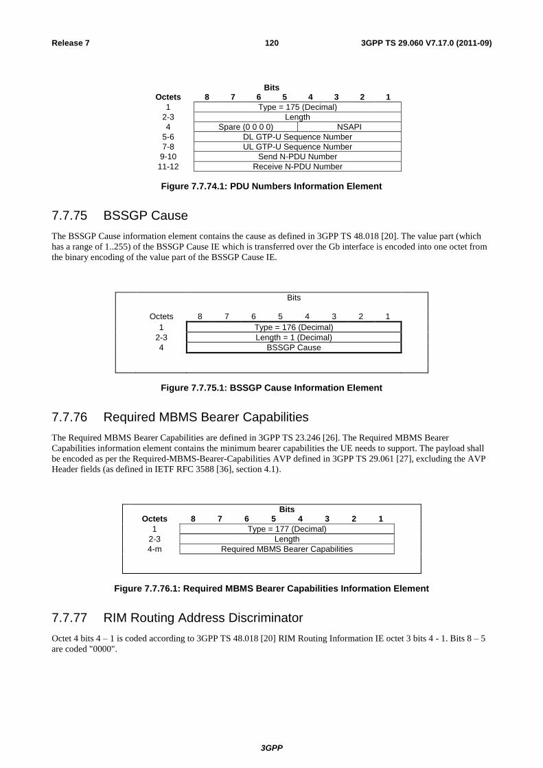
3GPP
3GPP TS 29.060 V7.17.0 (2011-09) 120 Release 7
Bits Octets 8 7 6 5 4 3 2 1
1 Type = 175 (Decimal)
2-3 Length
4 Spare (0 0 0 0) NSAPI
5-6 DL GTP-U Sequence Number
7-8 UL GTP-U Sequence Number
9-10 Send N-PDU Number
11-12 Receive N-PDU Number
Figure 7.7.74.1: PDU Numbers Information Element
7.7.75 BSSGP Cause
The BSSGP Cause information element contains the cause as defined in 3GPP TS 48.018 [20]. The value part (which
has a range of 1..255) of the BSSGP Cause IE which is transferred over the Gb interface is encoded into one octet from
the binary encoding of the value part of the BSSGP Cause IE.
Bits
Octets 8 7 6 5 4 3 2 1
1 Type = 176 (Decimal)
2-3 Length = 1 (Decimal)
4 BSSGP Cause
Figure 7.7.75.1: BSSGP Cause Information Element
7.7.76 Required MBMS Bearer Capabilities
The Required MBMS Bearer Capabilities are defined in 3GPP TS 23.246 [26]. The Required MBMS Bearer
Capabilities information element contains the minimum bearer capabilities the UE needs to support. The payload shall
be encoded as per the Required-MBMS-Bearer-Capabilities AVP defined in 3GPP TS 29.061 [27], excluding the AVP
Header fields (as defined in IETF RFC 3588 [36], section 4.1).
Bits Octets 8 7 6 5 4 3 2 1
1 Type = 177 (Decimal)
2-3 Length
4-m Required MBMS Bearer Capabilities
Figure 7.7.76.1: Required MBMS Bearer Capabilities Information Element
7.7.77 RIM Routing Address Discriminator
Octet 4 bits 4 – 1 is coded according to 3GPP TS 48.018 [20] RIM Routing Information IE octet 3 bits 4 - 1. Bits 8 – 5
are coded "0000".
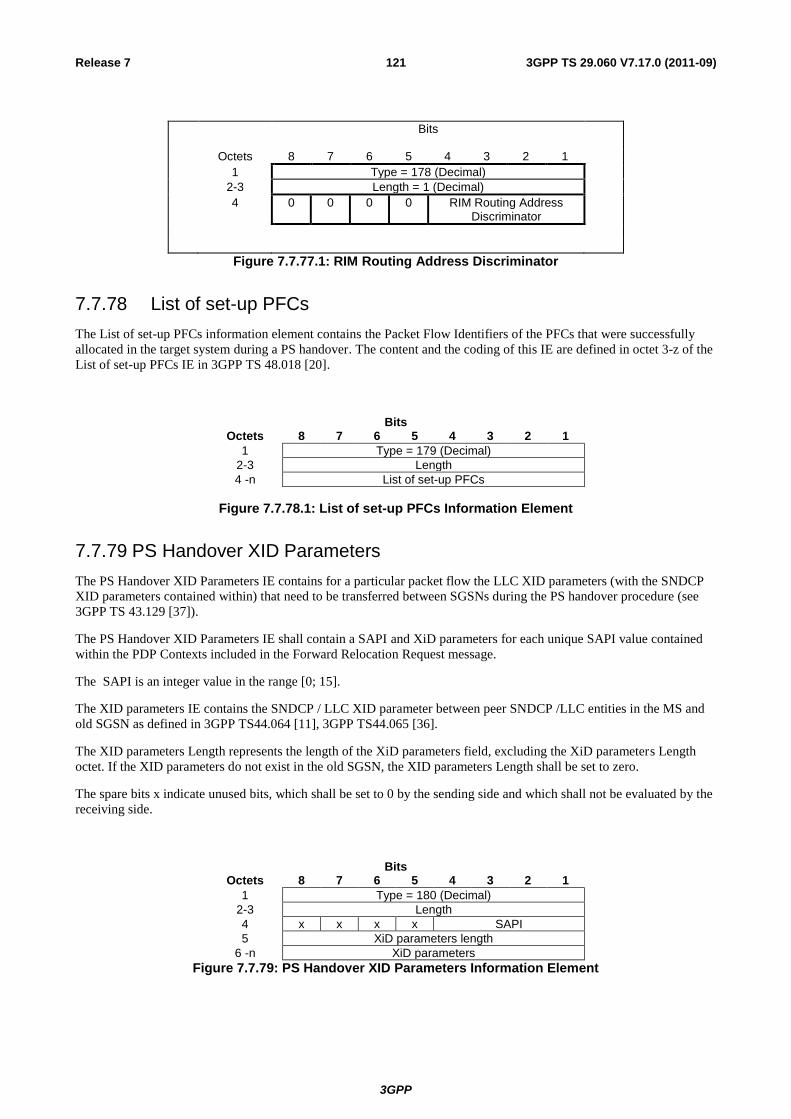
3GPP
3GPP TS 29.060 V7.17.0 (2011-09) 121 Release 7
Bits
Octets 8 7 6 5 4 3 2 1
1 Type = 178 (Decimal)
2-3 Length = 1 (Decimal)
4 0 0 0 0 RIM Routing Address Discriminator
Figure 7.7.77.1: RIM Routing Address Discriminator
7.7.78 List of set-up PFCs
The List of set-up PFCs information element contains the Packet Flow Identifiers of the PFCs that were successfully
allocated in the target system during a PS handover. The content and the coding of this IE are defined in octet 3-z of the
List of set-up PFCs IE in 3GPP TS 48.018 [20].
Bits Octets 8 7 6 5 4 3 2 1
1 Type = 179 (Decimal)
2-3 Length
4 -n List of set-up PFCs
Figure 7.7.78.1: List of set-up PFCs Information Element
7.7.79 PS Handover XID Parameters
The PS Handover XID Parameters IE contains for a particular packet flow the LLC XID parameters (with the SNDCP
XID parameters contained within) that need to be transferred between SGSNs during the PS handover procedure (see
3GPP TS 43.129 [37]).
The PS Handover XID Parameters IE shall contain a SAPI and XiD parameters for each unique SAPI value contained
within the PDP Contexts included in the Forward Relocation Request message.
The SAPI is an integer value in the range [0; 15].
The XID parameters IE contains the SNDCP / LLC XID parameter between peer SNDCP /LLC entities in the MS and
old SGSN as defined in 3GPP TS44.064 [11], 3GPP TS44.065 [36].
The XID parameters Length represents the length of the XiD parameters field, excluding the XiD parameters Length
octet. If the XID parameters do not exist in the old SGSN, the XID parameters Length shall be set to zero.
The spare bits x indicate unused bits, which shall be set to 0 by the sending side and which shall not be evaluated by the
receiving side.
Bits Octets 8 7 6 5 4 3 2 1
1 Type = 180 (Decimal)
2-3 Length
4 x x x x SAPI
5 XiD parameters length
6 -n XiD parameters
Figure 7.7.79: PS Handover XID Parameters Information Element
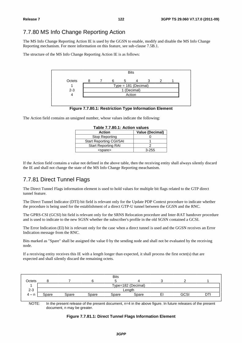
3GPP
3GPP TS 29.060 V7.17.0 (2011-09) 122 Release 7
7.7.80 MS Info Change Reporting Action
The MS Info Change Reporting Action IE is used by the GGSN to enable, modify and disable the MS Info Change
Reporting mechanism. For more information on this feature, see sub-clause 7.5B.1.
The structure of the MS Info Change Reporting Action IE is as follows:
Bits
Octets 8 7 6 5 4 3 2 1
1 Type = 181 (Decimal)
2-3 1 (Decimal)
4 Action
Figure 7.7.80.1: Restriction Type Information Element
The Action field contains an unsigned number, whose values indicate the following:
Table 7.7.80.1: Action valuesAction Value (Decimal)
Stop Reporting 0
Start Reporting CGI/SAI 1
Start Reporting RAI 2
<spare> 3-255
If the Action field contains a value not defined in the above table, then the receiving entity shall always silently discard
the IE and shall not change the state of the MS Info Change Reporting meachanism.
7.7.81 Direct Tunnel Flags
The Direct Tunnel Flags information element is used to hold values for multiple bit flags related to the GTP direct
tunnel feature.
The Direct Tunnel Indicator (DTI) bit field is relevant only for the Update PDP Context procedure to indicate whether
the procedure is being used for the establishment of a direct GTP-U tunnel between the GGSN and the RNC.
The GPRS-CSI (GCSI) bit field is relevant only for the SRNS Relocation procedure and Inter-RAT handover procedure
and is used to indicate to the new SGSN whether the subscriber's profile in the old SGSN contained a GCSI.
The Error Indication (EI) bit is relevant only for the case when a direct tunnel is used and the GGSN receives an Error
Indication message from the RNC.
Bits marked as "Spare" shall be assigned the value 0 by the sending node and shall not be evaluated by the receiving
node.
If a receiving entity receives this IE with a length longer than expected, it shall process the first octet(s) that are
expected and shall silently discard the remaining octets.
Bits Octets 8 7 6 5 4 3 2 1
1 Type=182 (Decimal)
2-3 Length
4 – n Spare Spare Spare Spare Spare EI GCSI DTI
NOTE: In the present release of the present document, n=4 in the above figure. In future releases of the present document, n may be greater.
Figure 7.7.81.1: Direct Tunnel Flags Information Element
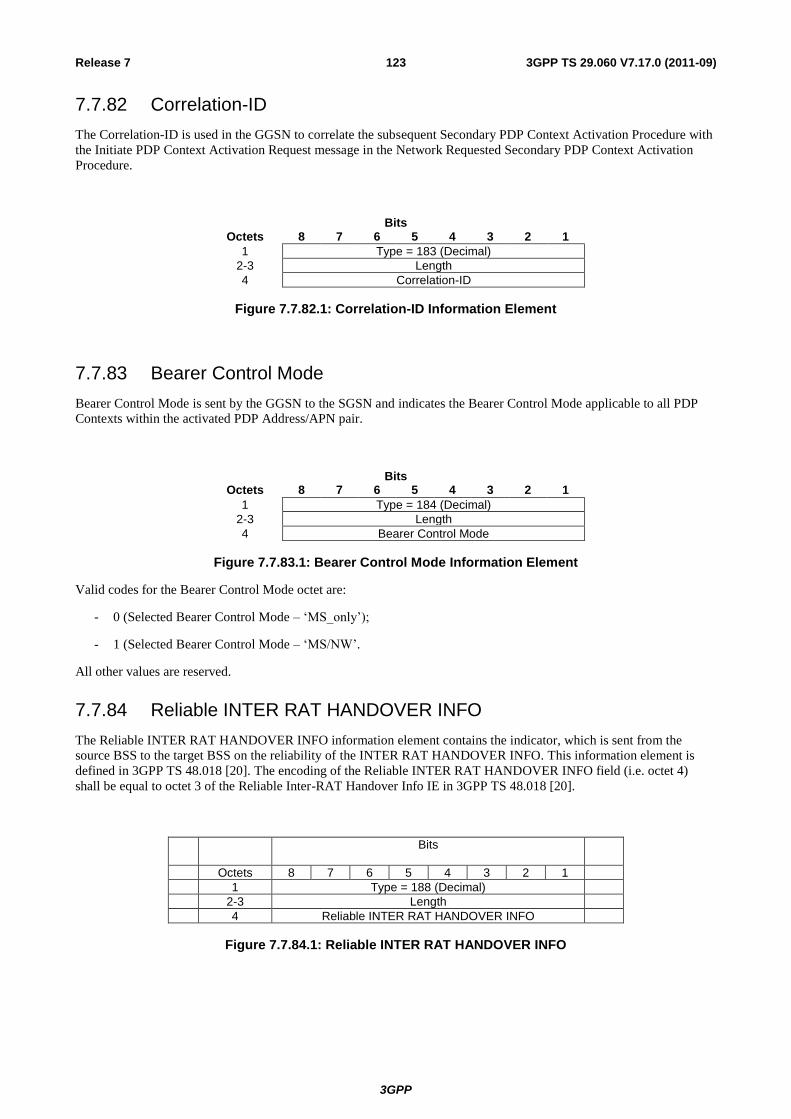
3GPP
3GPP TS 29.060 V7.17.0 (2011-09) 123 Release 7
7.7.82 Correlation-ID
The Correlation-ID is used in the GGSN to correlate the subsequent Secondary PDP Context Activation Procedure with
the Initiate PDP Context Activation Request message in the Network Requested Secondary PDP Context Activation
Procedure.
Bits Octets 8 7 6 5 4 3 2 1
1 Type = 183 (Decimal)
2-3 Length
4 Correlation-ID
Figure 7.7.82.1: Correlation-ID Information Element
7.7.83 Bearer Control Mode
Bearer Control Mode is sent by the GGSN to the SGSN and indicates the Bearer Control Mode applicable to all PDP
Contexts within the activated PDP Address/APN pair.
Bits Octets 8 7 6 5 4 3 2 1
1 Type = 184 (Decimal)
2-3 Length
4 Bearer Control Mode
Figure 7.7.83.1: Bearer Control Mode Information Element Valid codes for the Bearer Control Mode octet are:
- 0 (Selected Bearer Control Mode – ‘MS_only’);
- 1 (Selected Bearer Control Mode – ‘MS/NW’.
All other values are reserved.
7.7.84 Reliable INTER RAT HANDOVER INFO
The Reliable INTER RAT HANDOVER INFO information element contains the indicator, which is sent from the
source BSS to the target BSS on the reliability of the INTER RAT HANDOVER INFO. This information element is
defined in 3GPP TS 48.018 [20]. The encoding of the Reliable INTER RAT HANDOVER INFO field (i.e. octet 4)
shall be equal to octet 3 of the Reliable Inter-RAT Handover Info IE in 3GPP TS 48.018 [20].
Bits
Octets 8 7 6 5 4 3 2 1
1 Type = 188 (Decimal)
2-3 Length
4 Reliable INTER RAT HANDOVER INFO
Figure 7.7.84.1: Reliable INTER RAT HANDOVER INFO
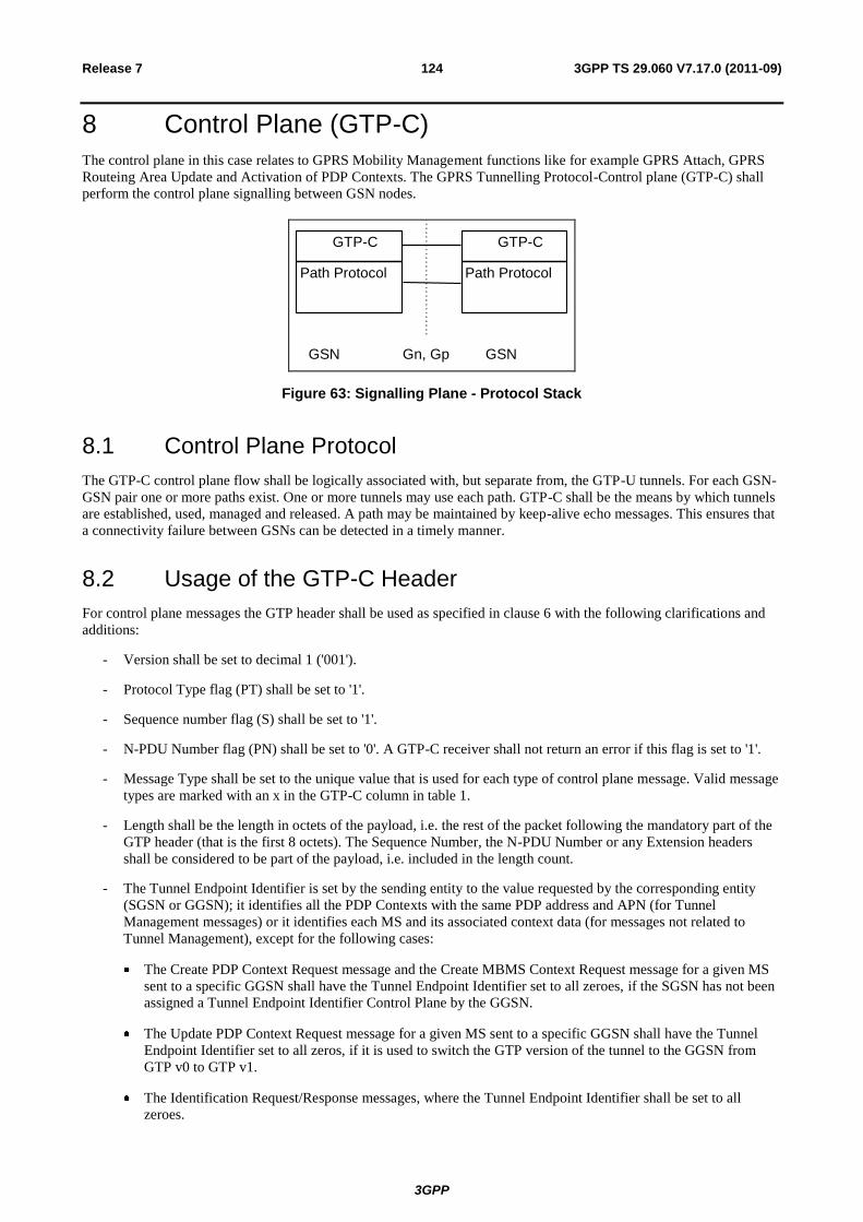
3GPP
3GPP TS 29.060 V7.17.0 (2011-09) 124 Release 7
8 Control Plane (GTP-C)
The control plane in this case relates to GPRS Mobility Management functions like for example GPRS Attach, GPRS
Routeing Area Update and Activation of PDP Contexts. The GPRS Tunnelling Protocol-Control plane (GTP-C) shall
perform the control plane signalling between GSN nodes.
GSN Gn, Gp GSN
GTP-C
Path Protocol
GTP-C
Path Protocol
Figure 63: Signalling Plane - Protocol Stack
8.1 Control Plane Protocol
The GTP-C control plane flow shall be logically associated with, but separate from, the GTP-U tunnels. For each GSN-
GSN pair one or more paths exist. One or more tunnels may use each path. GTP-C shall be the means by which tunnels
are established, used, managed and released. A path may be maintained by keep-alive echo messages. This ensures that
a connectivity failure between GSNs can be detected in a timely manner.
8.2 Usage of the GTP-C Header
For control plane messages the GTP header shall be used as specified in clause 6 with the following clarifications and
additions:
- Version shall be set to decimal 1 ('001').
- Protocol Type flag (PT) shall be set to '1'.
- Sequence number flag (S) shall be set to '1'.
- N-PDU Number flag (PN) shall be set to '0'. A GTP-C receiver shall not return an error if this flag is set to '1'.
- Message Type shall be set to the unique value that is used for each type of control plane message. Valid message
types are marked with an x in the GTP-C column in table 1.
- Length shall be the length in octets of the payload, i.e. the rest of the packet following the mandatory part of the
GTP header (that is the first 8 octets). The Sequence Number, the N-PDU Number or any Extension headers
shall be considered to be part of the payload, i.e. included in the length count.
- The Tunnel Endpoint Identifier is set by the sending entity to the value requested by the corresponding entity
(SGSN or GGSN); it identifies all the PDP Contexts with the same PDP address and APN (for Tunnel
Management messages) or it identifies each MS and its associated context data (for messages not related to
Tunnel Management), except for the following cases:
The Create PDP Context Request message and the Create MBMS Context Request message for a given MS
sent to a specific GGSN shall have the Tunnel Endpoint Identifier set to all zeroes, if the SGSN has not been
assigned a Tunnel Endpoint Identifier Control Plane by the GGSN.
The Update PDP Context Request message for a given MS sent to a specific GGSN shall have the Tunnel
Endpoint Identifier set to all zeros, if it is used to switch the GTP version of the tunnel to the GGSN from
GTP v0 to GTP v1.
The Identification Request/Response messages, where the Tunnel Endpoint Identifier shall be set to all
zeroes.

3GPP
3GPP TS 29.060 V7.17.0 (2011-09) 125 Release 7
The SGSN Context Request message, where the Tunnel Endpoint Identifier shall be set to all zeroes.
The Echo Request/Response, Supported Extension Headers notification and the Version Not Supported
messages, where the Tunnel Endpoint Identifier shall be set to all zeroes.
The Forward Relocation Request message, where the Tunnel Endpoint Identifier shall be set to all zeroes.
The PDU Notification Request message, where the Tunnel Endpoint Identifier shall be set to all zeroes.
The MBMS Notification Request message, where the Tunnel Endpoint Identifier shall be set to all zeroes.
The RAN Information Relay message, where the Tunnel Endpoint Identifier shall be set to all zeroes.
The Relocation Cancel Request message where the Tunnel Endpoint Identifier shall be set to all zeroes,
except for the case where the old SGSN has already been assigned the Tunnel Endpoint Identifier Control
Plane of the new SGSN.
All Location Management messages, where the Tunnel Endpoint Identifier shall be set to all zeroes.
If a GSN receives a GTP-C message requesting action related to a PDP context that the sending node
believes is in existence, but that is not recognised by the receiving node, the receiving node shall send back to
the source of the message, a response with the appropriate cause value (either 'Non-existent' or 'Context not
found'). The Tunnel Endoint Identifier used in the response message shall be set to all zeroes.
The MBMS Registration Request message , if successful assignment of Tunnel Endpoint Identifier Control
Plane has not been confirmed, and, for MBMS Broadcast, the MBMS Session Start Request message, where
the Tunnel Endpoint Identifier shall be set to all zeroes.
The MS Info Change Reporting messages, where the Tunnel Endpoint Identifier shall be set to all zeroes.
The GSN Address for Control Plane set in the request message could be different from the IP Source address of
the message. The Tunnel Endpoint Identifier notified in the request message is also used in this case for sending
the corresponding response message.
- Sequence Number shall be a message number valid for a path. Within a given set of contiguous Sequence
Numbers from 0 to 65535, a given Sequence Number shall, if used, unambiguously define a GTP control plane
request message sent on the path (see section Reliable delivery of signalling messages). The Sequence Number
in a control plane response message shall be copied from the control plane request message that the GSN is
replying to. For GTP-C messages not having a defined response message for a request message, i.e. for messages
Version Not Supported, RAN Information Relay and Supported Extension Headers Notification, the Sequence
Number shall be ignored by the receiver.
- N-PDU Number shall not be interpreted.
The GTP-C header may be followed by subsequent information elements dependent on the type of control plane
message. Only one information element of each type is allowed in a single control plane message, except for the
Authentication Triplet, the PDP Context, the Tunnel Endpoint Identifier Data II, NSAPI, PS Handover XID
Parameters, Packet Flow ID, and PDU Numbers information element where several occurrences of each type are
allowed.
Bits Octets 8 7 6 5 4 3 2 1
1 – m GTP header
m - n Information Element(s)
Figure 64: GTP Header followed by subsequent Information Elements

3GPP
3GPP TS 29.060 V7.17.0 (2011-09) 126 Release 7
9 GTP-U
GTP-U Tunnels are used to carry encapsulated T-PDUs and signalling messages between a given pair of GTP-U Tunnel
Endpoints. The Tunnel Endpoint ID (TEID) which is present in the GTP header shall indicate which tunnel a particular
T-PDU belongs to. In this manner, packets are multiplexed and de-multiplexed by GTP-U between a given pair of
Tunnel Endpoints. The TEID value to be used in the TEID field shall be negotiated for instance during the GTP-C
Create PDP Context and the RAB assignment procedures that take place on the control plane.
The maximum size of a T-PDU that may be transmitted without fragmentation by GGSN or the MS is defined in
3GPP TS 23.060 [4]. The GGSN shall fragment, reject or discard T-PDUs, depending on the PDP type and
implementation decisions, directed to the MS if the T-PDU size exceeds the maximum size. The decision if the T-PDUs
shall be fragmented or discarded is dependent on the external packet data network protocol.
9.1 GTP-U Protocol Entity
The GTP-U protocol entity provides packet transmission and reception services to user plane entities in the GGSN, in
the SGSN and, in UMTS systems, in the RNC. The GTP-U protocol entity receives traffic from a number of GTP-U
tunnel endpoints and transmits traffic to a number of GTP-U tunnel endpoints. There is a GTP-U protocol entity per IP
address.
The TEID in the GTP-U header is used to de-multiplex traffic incoming from remote tunnel endpoints so that it is
delivered to the User plane entities in a way that allows multiplexing of different users, different packet protocols and
different QoS levels. Therefore no two remote GTP-U endpoints shall send traffic to a GTP-U protocol entity using the
same TEID value except for data forwarding as part of the SRNS relocation or Intersystem Change procedures.
9.1.1 Handling of Sequence Numbers
This functionality is provided only when the S bit is set to 1 in the GTP-U header.
The GTP-U protocol entity must reorder out of sequence T-PDUs when in sequence delivery is required. This is
optional at the SGSN in UMTS. The GTP-U protocol entity shall deliver to the user plane entity only in sequence
T-PDUs and notify the sequence number associated to each of them. The notification of the sequence number is not
necessary at the GGSN, but it is mandatory at the SGSN and RNC. The user plane entity shall provide a sequence
number to the GTP-U layer together with T-PDUs to be transmitted in sequence. GTP-U protocol entities at the GGSN
may optionally generate autonomously the sequence number, but should be able to use sequence numbers provided by
the user plane entity. The sequence number is handled on a per GTP-U Tunnel (that is TEID) basis.
When the sequence number is included in the GTP-U header, a user plane entity acting as a relay of T-PDUs between
GTP-U protocol entities, or between PDCP (or SNDCP) protocol entities and GTP-U protocol entities, shall relay the
sequence numbers between those entities as well. In this way it is possible to keep consistent values of sequence
numbers from the GGSN to the UE (MS in GPRS) by relaying the sequence number across the CN GTP-U bearer, the
Iu GTP-U bearer and the Radio bearer (via PDCP or SNDCP N-PDU numbers). This functionality is beneficial during
SRNS relocation.
For GTP-U signalling messages having a response message defined for a request message, Sequence Number shall be a
message number valid for a path. Within a given set of continuous Sequence Numbers from 0 to 65535, a given
Sequence Number shall, if used, unambiguously define a GTP-U signalling request message sent on the path (see
section Reliable delivery of signalling messages). The Sequence Number in a signalling response message shall be
copied from the signalling request message that the GSN or RNC is replying to. For GTP-U messages not having a
defined response message for a request message, i.e. for messages Supported Extension Headers Notification and Error
Indication, the Sequence Number shall be ignored by the receiver.
9.2 GTP-U Service Access Points and Primitives
The GTP-U protocol entity offers packet Transmission services between a pair of GTP-U tunnel endpoints. The tunnel
between two GTP-U endpoints is established via control plane procedures defined in protocols such as GTP-C and
RANAP. The control of GTP-U resource allocation and tunnel set-up takes place via the GTP-U-CONTROL SAP. The
GTP-U packet transmission (and packet reception) services are accessed via the GTP-U-UNIT-DATA SAP.
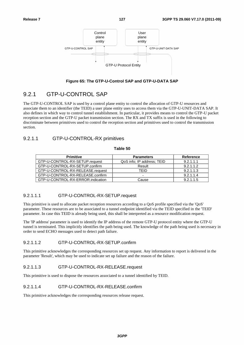
3GPP
3GPP TS 29.060 V7.17.0 (2011-09) 127 Release 7
GTP-U Protocol Entity
Control
plane
entity
User
plane
entity
GTP-U-CONTROL SAP GTP-U-UNIT-DATA SAP
Figure 65: The GTP-U-Control SAP and GTP-U-DATA SAP
9.2.1 GTP-U-CONTROL SAP
The GTP-U-CONTROL SAP is used by a control plane entity to control the allocation of GTP-U resources and
associate them to an identifier (the TEID) a user plane entity uses to access them via the GTP-U-UNIT-DATA SAP. It
also defines in which way to control tunnel establishment. In particular, it provides means to control the GTP-U packet
reception section and the GTP-U packet transmission section. The RX and TX suffix is used in the following to
discriminate between primitives used to control the reception section and primitives used to control the transmission
section.
9.2.1.1 GTP-U-CONTROL-RX primitives
Table 50
Primitive Parameters Reference
GTP-U-CONTROL-RX-SETUP.request QoS info; IP address; TEID 9.2.1.1.1
GTP-U-CONTROL-RX-SETUP.confirm Result 9.2.1.1.2
GTP-U-CONTROL-RX-RELEASE.request TEID 9.2.1.1.3
GTP-U-CONTROL-RX-RELEASE.confirm - 9.2.1.1.4
GTP-U-CONTROL-RX-ERROR.indication Cause 9.2.1.1.5
9.2.1.1.1 GTP-U-CONTROL-RX-SETUP.request
This primitive is used to allocate packet reception resources according to a QoS profile specified via the 'QoS'
parameter. These resources are to be associated to a tunnel endpoint identified via the TEID specified in the 'TEID'
parameter. In case this TEID is already being used, this shall be interpreted as a resource modification request.
The 'IP address' parameter is used to identify the IP address of the remote GTP-U protocol entity where the GTP-U
tunnel is terminated. This implicitly identifies the path being used. The knowledge of the path being used is necessary in
order to send ECHO messages used to detect path failure.
9.2.1.1.2 GTP-U-CONTROL-RX-SETUP.confirm
This primitive acknowledges the corresponding resources set up request. Any information to report is delivered in the
parameter 'Result', which may be used to indicate set up failure and the reason of the failure.
9.2.1.1.3 GTP-U-CONTROL-RX-RELEASE.request
This primitive is used to dispose the resources associated to a tunnel identified by TEID.
9.2.1.1.4 GTP-U-CONTROL-RX-RELEASE.confirm
This primitive acknowledges the corresponding resources release request.
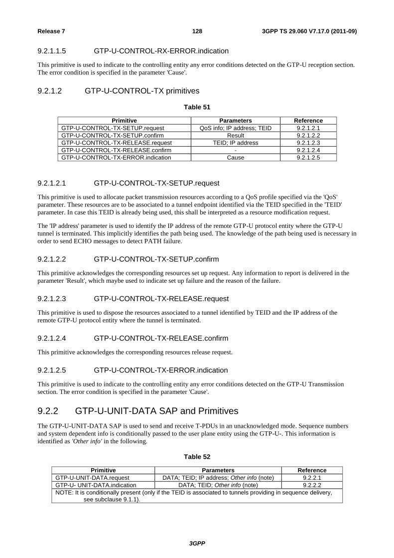
3GPP
3GPP TS 29.060 V7.17.0 (2011-09) 128 Release 7
9.2.1.1.5 GTP-U-CONTROL-RX-ERROR.indication
This primitive is used to indicate to the controlling entity any error conditions detected on the GTP-U reception section.
The error condition is specified in the parameter 'Cause'.
9.2.1.2 GTP-U-CONTROL-TX primitives
Table 51
Primitive Parameters Reference
GTP-U-CONTROL-TX-SETUP.request QoS info; IP address; TEID 9.2.1.2.1
GTP-U-CONTROL-TX-SETUP.confirm Result 9.2.1.2.2
GTP-U-CONTROL-TX-RELEASE.request TEID; IP address 9.2.1.2.3
GTP-U-CONTROL-TX-RELEASE.confirm - 9.2.1.2.4
GTP-U-CONTROL-TX-ERROR.indication Cause 9.2.1.2.5
9.2.1.2.1 GTP-U-CONTROL-TX-SETUP.request
This primitive is used to allocate packet transmission resources according to a QoS profile specified via the 'QoS'
parameter. These resources are to be associated to a tunnel endpoint identified via the TEID specified in the 'TEID'
parameter. In case this TEID is already being used, this shall be interpreted as a resource modification request.
The 'IP address' parameter is used to identify the IP address of the remote GTP-U protocol entity where the GTP-U
tunnel is terminated. This implicitly identifies the path being used. The knowledge of the path being used is necessary in
order to send ECHO messages to detect PATH failure.
9.2.1.2.2 GTP-U-CONTROL-TX-SETUP.confirm
This primitive acknowledges the corresponding resources set up request. Any information to report is delivered in the
parameter 'Result', which maybe used to indicate set up failure and the reason of the failure.
9.2.1.2.3 GTP-U-CONTROL-TX-RELEASE.request
This primitive is used to dispose the resources associated to a tunnel identified by TEID and the IP address of the
remote GTP-U protocol entity where the tunnel is terminated.
9.2.1.2.4 GTP-U-CONTROL-TX-RELEASE.confirm
This primitive acknowledges the corresponding resources release request.
9.2.1.2.5 GTP-U-CONTROL-TX-ERROR.indication
This primitive is used to indicate to the controlling entity any error conditions detected on the GTP-U Transmission
section. The error condition is specified in the parameter 'Cause'.
9.2.2 GTP-U-UNIT-DATA SAP and Primitives
The GTP-U-UNIT-DATA SAP is used to send and receive T-PDUs in an unacknowledged mode. Sequence numbers
and system dependent info is conditionally passed to the user plane entity using the GTP-U-. This information is
identified as 'Other info' in the following.
Table 52
Primitive Parameters Reference
GTP-U-UNIT-DATA.request DATA; TEID; IP address; Other info (note) 9.2.2.1
GTP-U- UNIT-DATA.indication DATA; TEID; Other info (note) 9.2.2.2
NOTE: It is conditionally present (only if the TEID is associated to tunnels providing in sequence delivery, see subclause 9.1.1).
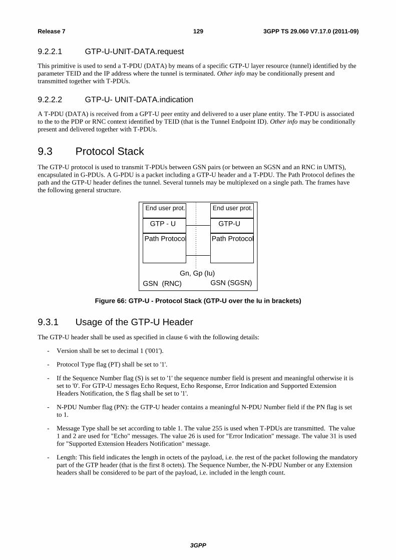
3GPP
3GPP TS 29.060 V7.17.0 (2011-09) 129 Release 7
9.2.2.1 GTP-U-UNIT-DATA.request
This primitive is used to send a T-PDU (DATA) by means of a specific GTP-U layer resource (tunnel) identified by the
parameter TEID and the IP address where the tunnel is terminated. Other info may be conditionally present and
transmitted together with T-PDUs.
9.2.2.2 GTP-U- UNIT-DATA.indication
A T-PDU (DATA) is received from a GPT-U peer entity and delivered to a user plane entity. The T-PDU is associated
to the to the PDP or RNC context identified by TEID (that is the Tunnel Endpoint ID). Other info may be conditionally
present and delivered together with T-PDUs.
9.3 Protocol Stack
The GTP-U protocol is used to transmit T-PDUs between GSN pairs (or between an SGSN and an RNC in UMTS),
encapsulated in G-PDUs. A G-PDU is a packet including a GTP-U header and a T-PDU. The Path Protocol defines the
path and the GTP-U header defines the tunnel. Several tunnels may be multiplexed on a single path. The frames have
the following general structure.
GSN (RNC)
Gn, Gp (Iu)
GSN (SGSN)
End user prot.
GTP - U
Path Protocol
End user prot.
GTP-U
Path Protocol
Figure 66: GTP-U - Protocol Stack (GTP-U over the Iu in brackets)
9.3.1 Usage of the GTP-U Header
The GTP-U header shall be used as specified in clause 6 with the following details:
- Version shall be set to decimal 1 ('001').
- Protocol Type flag (PT) shall be set to '1'.
- If the Sequence Number flag (S) is set to '1' the sequence number field is present and meaningful otherwise it is
set to '0'. For GTP-U messages Echo Request, Echo Response, Error Indication and Supported Extension
Headers Notification, the S flag shall be set to '1'.
- N-PDU Number flag (PN): the GTP-U header contains a meaningful N-PDU Number field if the PN flag is set
to 1.
- Message Type shall be set according to table 1. The value 255 is used when T-PDUs are transmitted. The value
1 and 2 are used for "Echo" messages. The value 26 is used for "Error Indication" message. The value 31 is used
for "Supported Extension Headers Notification" message.
- Length: This field indicates the length in octets of the payload, i.e. the rest of the packet following the mandatory
part of the GTP header (that is the first 8 octets). The Sequence Number, the N-PDU Number or any Extension
headers shall be considered to be part of the payload, i.e. included in the length count.
3GPP
3GPP TS 29.060 V7.17.0 (2011-09) 130 Release 7
- Sequence Number: This field is meaningful if and only if the S field is set to 1. Its presence is defined in
clause 6. The handling of this field is specified in subclause 9.1.1. It shall be used in order to decide whether or
not to discard a received T-PDU, as specified in subclause 9.3.1.1 Usage of the Sequence Number or as a
transaction identity for GTP-U signalling messages having a response message defined for a request message.
For GTP-U message, Supported Extension Headers Notification and Error Indication the Sequence Number shall
be ignored by the receiver.
- N-PDU Number: This field is meaningful if and only if the PN flag is set to 1. Its presence is defined in clause 6.
In this case, the old SGSN (or RNC) uses it, at the Inter SGSN Routeing Area Update procedure (or SRNS
relocation), to inform the new SGSN (or RNC) of the N-PDU number assigned to T-PDU. If an N-PDU number
was not assigned to the T-PDU by PDCP, or if the T-PDU is to be transferred using unacknowledged peer-to-
peer LLC operation, then PN shall be set to 0.
- TEID: Contains the Tunnel Endpoint Identifier for the tunnel to which this T-PDU belongs. The TEID shall be
used by the receiving entity to find the PDP context, except for the following cases:
- The Echo Request/Response and Supported Extension Headers notification messages, where the Tunnel
Endpoint Identifier shall be set to all zeroes.
- The Error Indication message where the Tunnel Endpoint Identifier shall be set to all zeros.
9.3.1.1 Usage of Sequence Number
The sending GGSN and SRNC shall use 0 for the value of the Sequence Number of the first G-PDU in a tunnel, only
during the PDP context activation, and shall increment the Sequence Number for each following G-PDU. The value
shall wrap to zero after 65535.
The receiving GGSN and SRNC shall set the content of a counter to zero, only during the PDP context activation.
When the receiving GGSN and SRNC receives a valid G-PDU, it shall increment this counter by one. This counter shall
wrap to zero after 65535. It defines the 'Expected Sequence Number'.
Based on the received and Expected Sequence Number values, the receiving GGSN and SRNC may decide whether or
not to discard the received G-PDU. Annex A (Informative) describes a method to determine whether a received G-PDU
is valid.
The receiving GGSN and SRNC shall reorder the incoming T-PDUs in sequence if the Reordering Required flag in the
PDP context is set. In this case, if needed, the receiving GGSN and SRNC shall take into account a maximum number
of valid received frames and a maximum elapsed time to assume that a G-PDU was lost.
The G-PDU sequence numbers allocated by the GGSN (down-link) and SRNC (uplink) are kept unchanged irrespective
of the number of GTP tunnels the PDU is transferred over. Therefore, SGSN shall use on the Iu interface for down-link
PDUs the G-PDU sequence number received from the GGSN, and shall use on the Gn interface for uplink PDUs the G-
PDU sequence number received from the SRNC. In case of SRNS relocation and intersystem change, the SRNC and
SGSN shall tunnel PDUs without changing the G-PDU sequence numbers.
9.4 Tunnelling between SGSNs
T-PDUs, stored in the old SGSN and not yet sent to the MS, shall be tunnelled to the new SGSN as a part of the Inter
SGSN Routeing Update procedure described in 3GPP TS 23.060 [4]. Some T-PDUs may still be on their way from the
GGSN to the old SGSN because they have been sent before the tunnel change. These T-PDUs shall also be tunnelled to
the new SGSN.
For intersystem SRNS Relocation, the establishment of the GTP tunnel(s) for the forwarding of G-PDUs is as described
in the 3GPP TS 23.121 [17] and in the 3GPP TS 23.060 [4] specifications.
For PS Handover, the establishment of the GTP tunnel(s) for the forwarding of G-PDUs is as described in the 3GPP TS
43.129 [37].
9.5 Tunnelling between Source RNC and Target RNC
For the 3G-3G SRNS Relocation, the establishment of the GTP tunnel for the forwarding of G-PDUs between source
and target RNC, is as described in the 3GPP TS 23.121 [17] and in the 3GPP TS 23.060 [4] specifications.
3GPP
3GPP TS 29.060 V7.17.0 (2011-09) 131 Release 7
9.6 Tunnelling between GGSNs
GTP shall not specify tunnelling between GGSNs. Transfer of MS-to-MS traffic between GGSNs shall use the Gi
interface.
10 Path Protocols
10.1 UDP/IP
UDP/IP is the only path protocol defined to transfer GTP messages in the version 1 of GTP. A User Datagram Protocol
(UDP) compliant with RFC 768 shall be used.
10.1.1 UDP Header
10.1.1.1 Request Messages
The UDP Destination Port number for GTP-C request messages is 2123. It is the registered port number for GTP-C.
The UDP Destination Port number for GTP-U request messages is 2152. It is the registered port number for GTP-U.
The UDP Source Port is a locally allocated port number at the sending GSN/RNC.
10.1.1.2 Response Messages
The UDP Destination Port value shall be the value of the UDP Source Port of the corresponding request message.
The UDP Source Port shall be the value from the UDP Destination Port of the corresponding request message.
10.1.1.3 Encapsulated T-PDUs
The UDP Destination Port number shall be 2152. It is the registered port number for GTP-U. The UDP Source Port is a
locally allocated port number at the sending GSN/RNC.
10.1.1.4 Error Indication, RAN Information Relay, Version Not Supported and Supported Extension Headers Notification
The UDP destination port for the Error Indication shall be the user plane UDP port (2152).
The UDP destination port for the Version Not Supported and the RAN Information Relay messages shall be the control
plane UDP port (2123).
The UDP destination port for the Supported Extension Headers Notification shall be the UDP port for User plane
(2152) if the trigger for it was a user plane message, the control plane port (2123) if the trigger for it was a control plane
message.
The UDP source port shall be locally assigned at the sending node.
10.1.2 IP Header
An Internet Protocol (IP) compliant with RFC 791 shall be used.
10.1.2.1 Request Messages and Encapsulated T-PDUs
The IP Source Address shall be an IP address of the source GSN/RNC from which the message is originating.
The IP Destination Address in a GTP request message shall be an IP address of the destination GSN/RNC. The IP
Destination Address in an encapsulated T-PDU GTP shall be an IP address of the destination GSN/RNC.

3GPP
3GPP TS 29.060 V7.17.0 (2011-09) 132 Release 7
10.1.2.2 Response Messages
The IP Source Address shall be an IP address of the source GSN/RNC from which the message is originating.
The IP Destination Address shall be copied from the IP Source Address of the GTP request message to which this
GSN/RNC is replying.
NOTE: The source IP address of the Echo Response message shall be the same as the destination IP address of
the Echo Request message.
10.1.2.3 Error Indication, RAN Information Relay, Version Not supported and Supported Extension Headers Notification
The IP source address shall be an address of the source GSN/RNC from which the message is originated. In particular,
the source Address of the "Version Not Supported" or the "Supported Extension Headers Notification" message, shall
be set to the destination address of the message that triggered the GSN/RNC to send the "Version Not Supported" or the
"Supported Extension Headers Notification" message.
The IP destination address for Error Indication, Version Not Supported and Supported Extension Headers Notification
shall be the source address of the GTP-PDU that is the cause for the GSN/RNC to send one of these messages. The IP
destination address for RAN Information Relay is the address of the SGSN which the messages is relayed to.
11 Error Handling
11.1 Protocol Errors
A protocol error is defined as a message with unknown, unforeseen or erroneous content. The term silently discarded
used in the following subclauses means that the implementation shall discard the message without further processing
and should log the event including the erroneous message and should include the error in a statistical counter.
An information element with 'Mandatory' in the 'Presence requirement' column of a message definition shall always be
present in that message.
The conditions for a conditional information element define whether the information element is semantically:
- mandatorily present;
- optionally present;
- mandatorily absent.
An information element, which is semantically mandatorily present but is omitted from the message, is treated as
missing data.
An information element, which is semantically mandatorily absent but is present in the message, is treated as
unexpected data.
The Error Indication, Version Not Supported, RAN Information Relay, Supported Extension Headers Notification and
the SGSN Context Acknowledge messages shall be considered as Responses for the purpose of this subclause.
The subclauses 11.1.1 to 11.1.13 shall be applied in decreasing priorities.
11.1.1 Different GTP Versions
If a receiving node receives a GTP message of an unsupported version, that node shall return a GTP Version Not
Supported message indicating in the Version field of the GTP header the latest GTP version that that node supports. The
received GTP-PDU shall then be discarded.
A GTP version '0' only GSN may not be listening on port 2123 and as such it will not be able to send back a Version
Not Supported message to a peer trying to establish a dialogue with it using GTP-C. As such, a GSN supporting both
version '1' and version '0' shall fall back to version '0' if the attempt to contact a peer using version '1' fails.
3GPP
3GPP TS 29.060 V7.17.0 (2011-09) 133 Release 7
It is an implementation option keeping a shortlist of recently contacted version '0' only GSNs, as well of the version
supported by those nodes sending back a Version Not Supported message.
11.1.2 GTP Message Too Short
When a GTP message is received, and is too short to contain the GTP header for the GTP version that the sender claims
to use, the GTP-PDU message shall be silently discarded.
11.1.3 Unknown GTP Signalling Message
When a message using a Message Type value defining an Unknown GTP signalling message is received, it shall be
silently discarded.
11.1.4 Unexpected GTP Signalling Message
When an unexpected GTP control plane message is received, e.g. a Response message for which there is no
corresponding outstanding Request, or a GTP control plane message a GSN is not expected to handle (such as a PDU
Notification Request received by a GGSN),, it shall be silently discarded.
11.1.5 Missing Mandatorily Present Information Element
The receiver of a GTP signalling Request message with a missing mandatorily present information element shall
discard the request, should log the error, and shall send a Response with Cause set to 'Mandatory IE missing'. The
receiver of a Response with a missing mandatory information element shall notify the upper layer and should log the
error.
11.1.6 Invalid Length
In a received GTP signalling message Request, a mandatory TLV format information element may have a Length
different from the Length defined in the version that this message claims to use. In this case, this information element
shall be discarded, the error should be logged, and a Response shall be sent with Cause set to 'Mandatory IE incorrect'.
In a received GTP signalling message Response, if a mandatory TLV format information element has a Length different
from the Length defined in the version that this message claims to use, then the requesting entity shall treat the GTP
signalling procedure as having failed.
11.1.7 Invalid Mandatory Information Element
The receiver of a GTP signalling message Request including a mandatory information element with a Value that is not
in the range defined for this information element value shall discard the request, should log the error, and shall send a
response with Cause set to 'Mandatory IE incorrect'.
The receiver of a GTP signalling message Response including a mandatory information element with a Value that is not
in the range defined for this information element shall notify the upper layer that a message with this sequence number
has been received and should log the error.
If a GSN receives an information element with a value which is shown as reserved, it shall treat that information
element as not being in the range defined for the information element.
NOTE: The receiver does not check the content of an information element field that is defined as 'spare'.
11.1.8 Invalid Optional Information Element
The receiver of a GTP signalling message including an optional information element with a Value that is not in the
range defined for this information element value shall discard this IE, should log the error, and shall treat the rest of the
message as if this IE was absent.
If a GSN receives an information element with a value which is shown as reserved, it shall treat that information
element as not being in the range defined for the information element.
3GPP
3GPP TS 29.060 V7.17.0 (2011-09) 134 Release 7
NOTE: The receiver does not check the content of an information element field that is defined as 'spare'.
11.1.9 Unknown Information Element
An information element with an unknown Type value shall be ignored by the receiver of the message. If this is a TLV
element, this information element shall be skipped using its Length value. If this is an unknown TV element, the
receiver shall discard the rest of the message. However, if the TV element is known but not expected, then the handling
defined in section 11.1.11 shall apply.
If the receiving node cannot interpret the rest of the message because of the ignored information element, the receiving
node shall discard the message and should log the error. If the message was a Request, it shall, in addition, return a
response with Cause set to 'Invalid message format'.
11.1.10 Out of Sequence Information Elements
If two or more information elements are out of sequence in a message, the receiving node shall discard the message and
should log the error. In addition, if the message was a Request, the receiving node shall return a Response with Cause
set to 'Invalid message format'.
11.1.11 Unexpected Information Element
An information element with a Type value which is defined in section 7.7 of the present specification but is not
expected in the received GTP signalling message shall be ignored (skipped) and the rest of the message processed as if
this information element was not present. For all information elements of type TV, a receiving entity shall be able to
determine how long each IE is, even if that IE should never be received in any message by that particular network
entity.
11.1.12 Repeated Information Elements
If an information element is repeated in a GTP signalling message in which repetition of the information element is not
specified, only the contents of the information element appearing first shall be handled and all subsequent repetitions of
the information element shall be ignored. When repetition of information elements is specified, only the contents of
specified repeated information elements shall be handled.
11.1.13 Incorrect Optional Information Elements
All optional information elements that are incorrect in a GTP signalling message shall be treated as not present in the
message. However, if the receiving node may not handle the message correctly because of the incorrect information
element, the receiving node should log the error and shall return a response with Cause set to 'Optional IE incorrect'.
11.2 Path Failure
A path counter shall be reset each time a response is received on the path and incremented when the T3-RESPONSE
timer expires for any message sent on the path. The path shall be considered to be down if the counter exceeds N3-
REQUESTS. In this case, the GSN or RNC may notify the Operation and Maintenance network element. GTP shall also
notify the upper layer of the path failure, so that PDP contexts associated with this path may be deleted
11.3 MS Detach
When an MS detaches, all ongoing GTP control plane procedures related to this MS shall be aborted. The SGSN shall
send Delete PDP Context Request messages for all active PDP contexts to the peer GGSNs.
11.4 Restoration and Recovery
All GSNs shall maintain in non-volatile memory a Restart Counter of local significance. A GSN that restarts shall
change the Restart Counter value immediately after the restart procedure has been completed. The value shall be
incremented by 1 modulo 256 (see 3GPP TS 23.007 [3]).
3GPP
3GPP TS 29.060 V7.17.0 (2011-09) 135 Release 7
All GSNs shall also maintain in volatile memory a Restart Counter for each GSN that it is in contact with. The Restart
Counters stored for all GSNs that it is in contact with shall be cleared after the restart procedure has been completed
(see 3GPP TS 23.007 [3]).
12 Security provided to GTP Communication over Gn and Gp Interfaces
Protection of GTP communication over Gn and Gp interfaces shall be provided according to security mechanisms
defined in 3GPP TS 33.210 [22].
13 IP, The Networking Technology used by GTP
13.1 IP Version
On the Gn and Gp interfaces the IPv4 (RFC 791) protocol shall be supported, IPv6 (RFC 2460) support is optional. This
also applies to the Iu interface, when the ATM transport option is applied. When the IP transport option is applied on
the Iu interface, both the IPv6 (RFC 2460) protocol and the IPv4 (RFC 791) protocol shall be supported.
13.2 IP Fragmentation
Here it is described how the fragmentation mechanism shall work together with GTP, when the GPRS backbone is
based on IPv4.
However, fragmentation should be avoided if possible. Examples of fragmentation drawbacks are, e.g.:
- Fragmentation is inefficient, since the complete IP header is duplicated in each fragment.
- If one fragment is lost, the complete packet has to be discarded. The reason is that no selective retransmission of
fragments is possible.
By using Path MTU discovery the application may find out the MTU, and thereby utilise more efficient segmentation
mechanisms in other protocol layers than IP.
The maximum size of a T-PDU that may be transmitted without fragmentation by GGSN or the MS is defined in 3GPP
TS 23.060 [4]. All backbone links should have MTU values that exceeds the sum of the maximum value plus the size of
the tunnel headers (IP header, UDP and GTP header) in order to avoid fragmentation in the backbone.
13.2.1 MO Direction
Functionality for IP fragmentation on the Iu interface is defined in 3GPP TS 25.414 [23].
SGSN: A packet from an MS shall be encapsulated at the SGSN with a GTP header, UDP and IP header. If the
resulting IP packet is larger than the MTU of the first link towards the GGSN, fragmentation of the IP packet shall be
performed by the SGSN. The SGSN should preferably fragment the IP packet if it is larger than the MTU of any link
between SGSN and GGSN.
Backbone router: Any router in the backbone may fragment the GTP packet if needed, according to IPv4.
GGSN: The GGSN shall assemble any IP fragments received from SGSNs, according to IPv4. Note that if any
fragment is lost, the whole packet shall be discarded.
13.2.2 MT Direction
Functionality for IP fragmentation on the Iu interface is defined in 3GPP TS 25.414 [23].
3GPP
3GPP TS 29.060 V7.17.0 (2011-09) 136 Release 7
GGSN: A packet from an external host shall be encapsulated at the GGSN with a GTP header, UDP and IP header. If
the resulting IP packet is larger than the MTU on the first link towards the SGSN, fragmentation of the IP packet shall
be performed by the GGSN. The GGSN should preferably fragment the IP packet if it is larger than the MTU of any
link between GGSN and SGSN.
Backbone Router: Any router in the backbone may fragment the GTP packet if needed, according to IPv4.
SGSN: The SGSN shall assemble any IP fragments received from the GGSN, according to IPv4. Note that if any
fragment is lost, the whole packet shall be discarded.
13.2.3 Tunnelling from old to new SGSN
Old SGSN: A user packet shall be encapsulated with a GTP header, UDP and IP header. If the resulting IP packet is
larger than the MTU on the first link towards the new SGSN, fragmentation of the IP packet shall be performed by the
old SGSN. The old SGSN should preferably fragment the IP packet if it is larger than the MTU of any link between old
and new SGSN.
Backbone router: Any router in the backbone may fragment the GTP packet if needed, according to IPv4.
New SGSN: The new SGSN shall assemble any IP fragments received from the old SGSN, according to IPv4. Note that
if any fragment is lost, the whole packet shall be discarded.
14 GTP Parameters
The GTP system parameters defined here and their recommended values shall not be fixed, but shall be possible to
configure as described in section 'Reliable delivery of messages'.
14.1 Timers
The timer T3-RESPONSE holds the maximum wait time for a response of a request message.
The timer T3-TUNNEL holds the time when PDUs shall be forwarded from the old SGSN to the new SGSN. The timer
is started in the old SGSN when it receives a GTP SGSN Context Request message and there is at least one active PDP
context. GTP shall indicate to the upper layer when the timer has expired. The recommended timer value is 20 s.
14.2 Others
The counter N3-REQUESTS holds the maximum number of attempts made by GTP to send a request message. The
recommended value is 5.
15 Mapping of BSSGP and RANAP causes
Table 15.1 through Table 15.4 define a mapping of BSSGP and RANAP causes used in connection with inter-RAT PS
Handover to avoid different mappings in different implementations.
Inter-RAT PS Handover from GERAN to UTRAN:
Table 15.1: Cause value mapping from PS HANDOVER REQUIRED to RELOCATION REQUEST
48.018 25.413
PS HANDOVER REQUIRED RELOCATION REQUEST
Uplink quality Time Critical Relocation
Uplink strength Time Critical Relocation
Downlink quality Time Critical Relocation
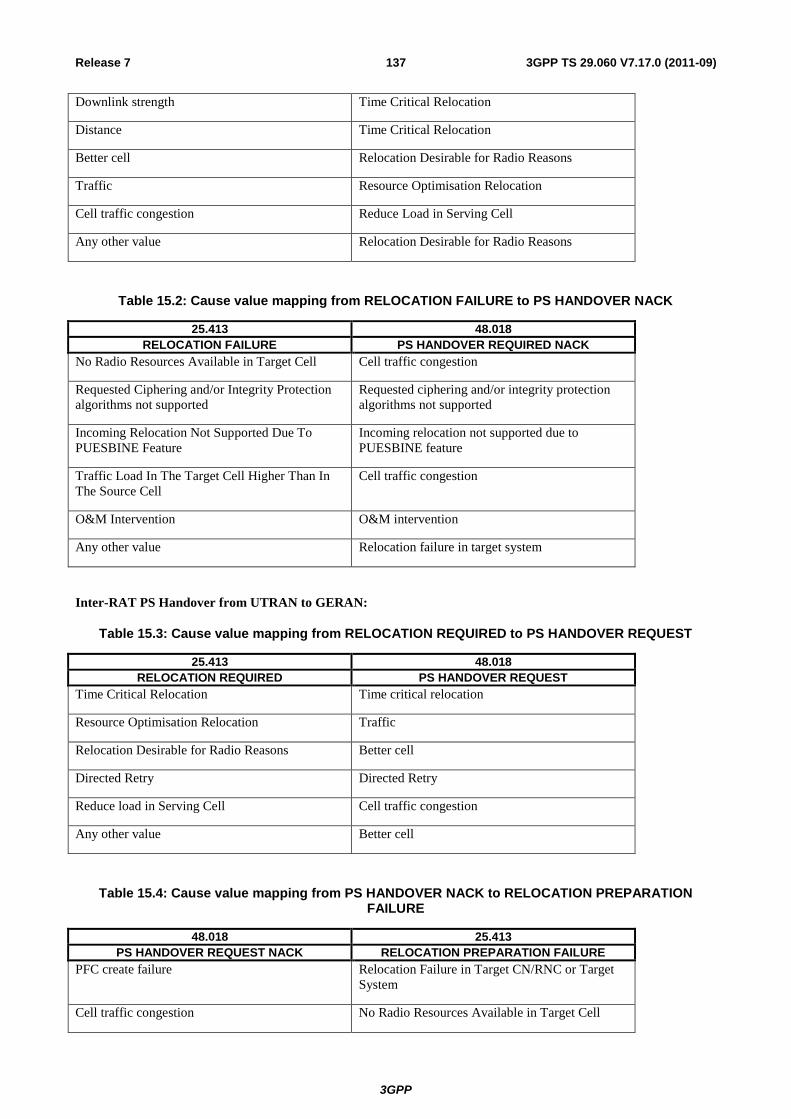
3GPP
3GPP TS 29.060 V7.17.0 (2011-09) 137 Release 7
Downlink strength Time Critical Relocation
Distance Time Critical Relocation
Better cell Relocation Desirable for Radio Reasons
Traffic Resource Optimisation Relocation
Cell traffic congestion Reduce Load in Serving Cell
Any other value Relocation Desirable for Radio Reasons
Table 15.2: Cause value mapping from RELOCATION FAILURE to PS HANDOVER NACK
25.413 48.018
RELOCATION FAILURE PS HANDOVER REQUIRED NACK
No Radio Resources Available in Target Cell Cell traffic congestion
Requested Ciphering and/or Integrity Protection
algorithms not supported
Requested ciphering and/or integrity protection
algorithms not supported
Incoming Relocation Not Supported Due To
PUESBINE Feature
Incoming relocation not supported due to
PUESBINE feature
Traffic Load In The Target Cell Higher Than In
The Source Cell
Cell traffic congestion
O&M Intervention O&M intervention
Any other value Relocation failure in target system
Inter-RAT PS Handover from UTRAN to GERAN:
Table 15.3: Cause value mapping from RELOCATION REQUIRED to PS HANDOVER REQUEST
25.413 48.018
RELOCATION REQUIRED PS HANDOVER REQUEST
Time Critical Relocation Time critical relocation
Resource Optimisation Relocation Traffic
Relocation Desirable for Radio Reasons Better cell
Directed Retry Directed Retry
Reduce load in Serving Cell Cell traffic congestion
Any other value Better cell
Table 15.4: Cause value mapping from PS HANDOVER NACK to RELOCATION PREPARATION FAILURE
48.018 25.413
PS HANDOVER REQUEST NACK RELOCATION PREPARATION FAILURE
PFC create failure Relocation Failure in Target CN/RNC or Target
System
Cell traffic congestion No Radio Resources Available in Target Cell
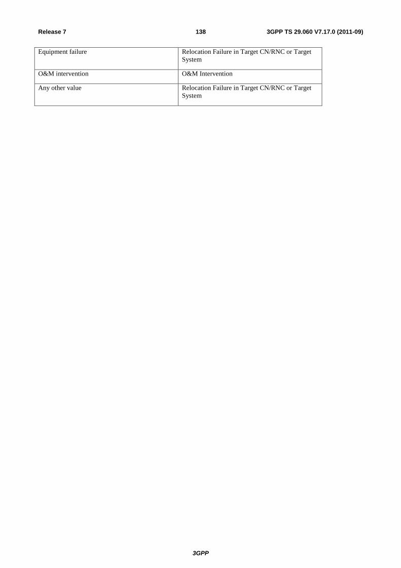
3GPP
3GPP TS 29.060 V7.17.0 (2011-09) 138 Release 7
Equipment failure Relocation Failure in Target CN/RNC or Target
System
O&M intervention O&M Intervention
Any other value Relocation Failure in Target CN/RNC or Target
System

3GPP
3GPP TS 29.060 V7.17.0 (2011-09) 139 Release 7
Annex A (informative): A method for sequence number checking
This annex describes a method to determine whether or not a received T-PDU is valid, for the Usage of the Sequence
Number, subclause 9.3.1.1.
This method deals with two distinct problems.
The first one is the 'drifting' between the Sequence Number value that we expect to receive in the light of the total
number of T-PDU received for this tunnel (the Expected value), and the effective received value. The probability that
the received T-PDU is not correct because not awaited is higher if the distance between expected and received
Sequence Numbers is high than if this distance is low. This leads to Condition 1. Its left part represents the distance
between the Expected and received values, in a circular 65536 dimension.
The second one is the duplication of T-PDU frames within a given number of last received frames that have been
accepted by the condition 1.
This leads to the following actions:
-This operation shall start when the dialogue is established between the GSNs. When each T-PDU is received during
the dialogue, if this T-PDU is valid, its Sequence Number shall be saved. The last 'A' saved Sequence Numbers
represent the 'Recorded Sequence Number Set'.
A received T-PDU sequence number is valid only if it satisfies both of the following conditions:
1) Min(Abs(E - r), Abs(r - 65536 - E), Abs(E - 65536 - r)) < 'B' Condition 1
Where: 'E' is the Expected Sequence Number and 'r' is the received Sequence Number.
2) The received Sequence Number is not a member of the Recorded Sequence Number Set. Condition 2.
'A' and 'B' are parameters. The receiving GSN shall discard a received T-PDU with an invalid Sequence Number.
Abs(X) represents the absolute value of the number X.
Min(X,Y,Z) represents the lowest value taken from the numbers X, Y, and Z.
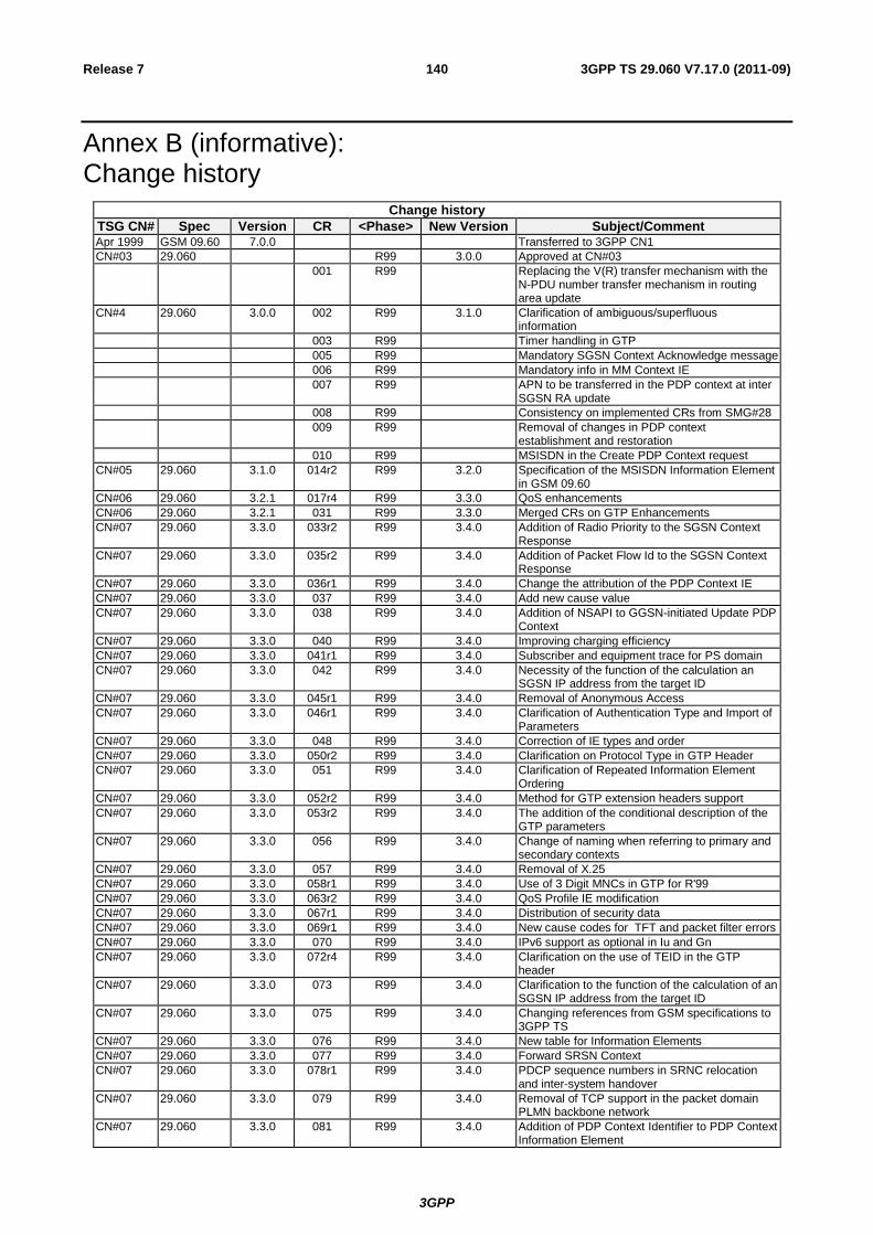
3GPP
3GPP TS 29.060 V7.17.0 (2011-09) 140 Release 7
Annex B (informative): Change history
Change history
TSG CN# Spec Version CR <Phase> New Version Subject/Comment Apr 1999 GSM 09.60 7.0.0 Transferred to 3GPP CN1
CN#03 29.060 R99 3.0.0 Approved at CN#03
001 R99 Replacing the V(R) transfer mechanism with the N-PDU number transfer mechanism in routing area update
CN#4 29.060 3.0.0 002 R99 3.1.0 Clarification of ambiguous/superfluous information
003 R99 Timer handling in GTP
005 R99 Mandatory SGSN Context Acknowledge message
006 R99 Mandatory info in MM Context IE
007 R99 APN to be transferred in the PDP context at inter SGSN RA update
008 R99 Consistency on implemented CRs from SMG#28
009 R99 Removal of changes in PDP context establishment and restoration
010 R99 MSISDN in the Create PDP Context request
CN#05 29.060 3.1.0 014r2 R99 3.2.0 Specification of the MSISDN Information Element in GSM 09.60
CN#06 29.060 3.2.1 017r4 R99 3.3.0 QoS enhancements
CN#06 29.060 3.2.1 031 R99 3.3.0 Merged CRs on GTP Enhancements
CN#07 29.060 3.3.0 033r2 R99 3.4.0 Addition of Radio Priority to the SGSN Context Response
CN#07 29.060 3.3.0 035r2 R99 3.4.0 Addition of Packet Flow Id to the SGSN Context Response
CN#07 29.060 3.3.0 036r1 R99 3.4.0 Change the attribution of the PDP Context IE
CN#07 29.060 3.3.0 037 R99 3.4.0 Add new cause value
CN#07 29.060 3.3.0 038 R99 3.4.0 Addition of NSAPI to GGSN-initiated Update PDP Context
CN#07 29.060 3.3.0 040 R99 3.4.0 Improving charging efficiency
CN#07 29.060 3.3.0 041r1 R99 3.4.0 Subscriber and equipment trace for PS domain
CN#07 29.060 3.3.0 042 R99 3.4.0 Necessity of the function of the calculation an SGSN IP address from the target ID
CN#07 29.060 3.3.0 045r1 R99 3.4.0 Removal of Anonymous Access
CN#07 29.060 3.3.0 046r1 R99 3.4.0 Clarification of Authentication Type and Import of Parameters
CN#07 29.060 3.3.0 048 R99 3.4.0 Correction of IE types and order
CN#07 29.060 3.3.0 050r2 R99 3.4.0 Clarification on Protocol Type in GTP Header
CN#07 29.060 3.3.0 051 R99 3.4.0 Clarification of Repeated Information Element Ordering
CN#07 29.060 3.3.0 052r2 R99 3.4.0 Method for GTP extension headers support
CN#07 29.060 3.3.0 053r2 R99 3.4.0 The addition of the conditional description of the GTP parameters
CN#07 29.060 3.3.0 056 R99 3.4.0 Change of naming when referring to primary and secondary contexts
CN#07 29.060 3.3.0 057 R99 3.4.0 Removal of X.25
CN#07 29.060 3.3.0 058r1 R99 3.4.0 Use of 3 Digit MNCs in GTP for R'99
CN#07 29.060 3.3.0 063r2 R99 3.4.0 QoS Profile IE modification
CN#07 29.060 3.3.0 067r1 R99 3.4.0 Distribution of security data
CN#07 29.060 3.3.0 069r1 R99 3.4.0 New cause codes for TFT and packet filter errors
CN#07 29.060 3.3.0 070 R99 3.4.0 IPv6 support as optional in Iu and Gn
CN#07 29.060 3.3.0 072r4 R99 3.4.0 Clarification on the use of TEID in the GTP header
CN#07 29.060 3.3.0 073 R99 3.4.0 Clarification to the function of the calculation of an SGSN IP address from the target ID
CN#07 29.060 3.3.0 075 R99 3.4.0 Changing references from GSM specifications to 3GPP TS
CN#07 29.060 3.3.0 076 R99 3.4.0 New table for Information Elements
CN#07 29.060 3.3.0 077 R99 3.4.0 Forward SRSN Context
CN#07 29.060 3.3.0 078r1 R99 3.4.0 PDCP sequence numbers in SRNC relocation and inter-system handover
CN#07 29.060 3.3.0 079 R99 3.4.0 Removal of TCP support in the packet domain PLMN backbone network
CN#07 29.060 3.3.0 081 R99 3.4.0 Addition of PDP Context Identifier to PDP Context Information Element
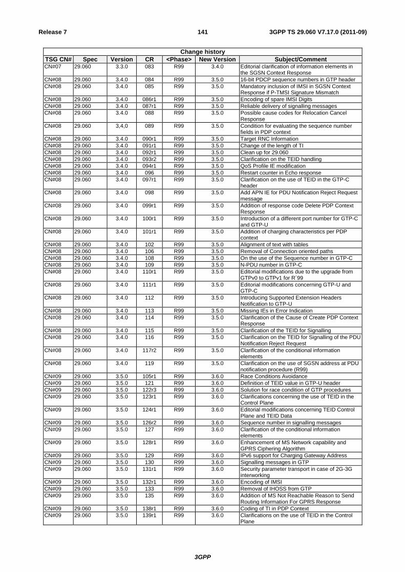
3GPP
3GPP TS 29.060 V7.17.0 (2011-09) 141 Release 7
Change history
TSG CN# Spec Version CR <Phase> New Version Subject/Comment CN#07 29.060 3.3.0 083 R99 3.4.0 Editorial clarification of information elements in
the SGSN Context Response
CN#08 29.060 3.4.0 084 R99 3.5.0 16-bit PDCP sequence numbers in GTP header
CN#08 29.060 3.4.0 085 R99 3.5.0 Mandatory inclusion of IMSI in SGSN Context Response if P-TMSI Signature Mismatch
CN#08 29.060 3.4.0 086r1 R99 3.5.0 Encoding of spare IMSI Digits
CN#08 29.060 3.4.0 087r1 R99 3.5.0 Reliable delivery of signalling messages
CN#08 29.060 3.4.0 088 R99 3.5.0 Possible cause codes for Relocation Cancel Response
CN#08 29.060 3,4,0 089 R99 3.5.0 Condition for evaluating the sequence number fields in PDP context
CN#08 29.060 3.4.0 090r1 R99 3.5.0 Target RNC Information
CN#08 29.060 3.4.0 091r1 R99 3.5.0 Change of the length of TI
CN#08 29.060 3.4.0 092r1 R99 3.5.0 Clean up for 29.060
CN#08 29.060 3.4.0 093r2 R99 3.5.0 Clarification on the TEID handling
CN#08 29.060 3.4.0 094r1 R99 3.5.0 QoS Profile IE modification
CN#08 29.060 3.4.0 096 R99 3.5.0 Restart counter in Echo response
CN#08 29.060 3.4.0 097r1 R99 3.5.0 Clarification on the use of TEID in the GTP-C header
CN#08 29.060 3.4.0 098 R99 3.5.0 Add APN IE for PDU Notification Reject Request message
CN#08 29.060 3.4.0 099r1 R99 3.5.0 Addition of response code Delete PDP Context Response
CN#08 29.060 3.4.0 100r1 R99 3.5.0 Introduction of a different port number for GTP-C and GTP-U
CN#08 29.060 3.4.0 101r1 R99 3.5.0 Addition of charging characteristics per PDP context
CN#08 29.060 3.4.0 102 R99 3.5.0 Alignment of text with tables
CN#08 29.060 3.4.0 106 R99 3.5.0 Removal of Connection oriented paths
CN#08 29.060 3.4.0 108 R99 3.5.0 On the use of the Sequence number in GTP-C
CN#08 29.060 3.4.0 109 R99 3.5.0 N-PDU number in GTP-C
CN#08 29.060 3.4.0 110r1 R99 3.5.0 Editorial modifications due to the upgrade from GTPv0 to GTPv1 for R´99
CN#08 29.060 3.4.0 111r1 R99 3.5.0 Editorial modifications concerning GTP-U and GTP-C
CN#08 29.060 3.4.0 112 R99 3.5.0 Introducing Supported Extension Headers Notification to GTP-U
CN#08 29.060 3.4.0 113 R99 3.5.0 Missing IEs in Error Indication
CN#08 29.060 3.4.0 114 R99 3.5.0 Clarification of the Cause of Create PDP Context Response
CN#08 29.060 3.4.0 115 R99 3.5.0 Clarification of the TEID for Signalling
CN#08 29.060 3.4.0 116 R99 3.5.0 Clarification on the TEID for Signalling of the PDU Notification Reject Request
CN#08 29.060 3.4.0 117r2 R99 3.5.0 Clarification of the conditional information elements
CN#08 29.060 3.4.0 119 R99 3.5.0 Clarification on the use of SGSN address at PDU notification procedure (R99)
CN#09 29.060 3.5.0 105r1 R99 3.6.0 Race Conditions Avoidance
CN#09 29.060 3.5.0 121 R99 3.6.0 Definition of TEID value in GTP-U header
CN#09 29.060 3.5.0 122r3 R99 3.6.0 Solution for race condition of GTP procedures
CN#09 29.060 3.5.0 123r1 R99 3.6.0 Clarifications concerning the use of TEID in the Control Plane
CN#09 29.060 3.5.0 124r1 R99 3.6.0 Editorial modifications concerning TEID Control Plane and TEID Data
CN#09 29.060 3.5.0 126r2 R99 3.6.0 Sequence number in signalling messages
CN#09 29.060 3.5.0 127 R99 3.6.0 Clarification of the conditional information elements
CN#09 29.060 3.5.0 128r1 R99 3.6.0 Enhancement of MS Network capability and GPRS Ciphering Algorithm
CN#09 29.060 3.5.0 129 R99 3.6.0 IPv6 support for Charging Gateway Address
CN#09 29.060 3.5.0 130 R99 3.6.0 Signalling messages in GTP
CN#09 29.060 3.5.0 131r1 R99 3.6.0 Security parameter transport in case of 2G-3G interworking
CN#09 29.060 3.5.0 132r1 R99 3.6.0 Encoding of IMSI
CN#09 29.060 3.5.0 133 R99 3.6.0 Removal of IHOSS from GTP
CN#09 29.060 3.5.0 135 R99 3.6.0 Addition of MS Not Reachable Reason to Send Routing Information For GPRS Response
CN#09 29.060 3.5.0 138r1 R99 3.6.0 Coding of TI in PDP Context
CN#09 29.060 3.5.0 139r1 R99 3.6.0 Clarifications on the use of TEID in the Control Plane
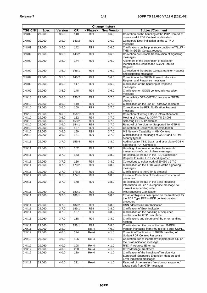
3GPP
3GPP TS 29.060 V7.17.0 (2011-09) 142 Release 7
Change history
TSG CN# Spec Version CR <Phase> New Version Subject/Comment CN#09 29.060 3.5.0 140 R99 3.6.0 Correction on the handling of the PDP Context at
unsuccessful PDP Context modification
CN#09 29.060 3.5.0 141r2 R99 3.6.0 Categorize Error indication as the GTP-U message
CN#09 29.060 3.5.0 142 R99 3.6.0 Clarifications on the presence condition of TLLI/P-TMSI in SGSN Context request
CN#09 29.060 3.5.0 143r2 R99 3.6.0 Correction on Reliable transmission of signalling messages
CN#09 29.060 3.5.0 144 R99 3.6.0 Alignment of the description of tables for Identification Request and SGSN Context Request
CN#09 29.060 3.5.0 145r1 R99 3.6.0 Correction to the SGSN Context transfer Request and response messages
CN#09 29.060 3.5.0 146r2 R99 3.6.0 Correction to the SGSN Forward relocation Request and Response messages
CN#09 29.060 3.5.0 147 R99 3.6.0 Clarification or the handling of response messages
CN#09 29.060 3.5.0 148 R99 3.6.0 Clarification on SGSN context acknowledge message
CN#10 29.060 3.6.0 136r2 R99 3.7.0 Compatibility GTPv0/GTPv1 in case of SGSN change
CN#10 29.060 3.6.0 149 R99 3.7.0 Clarification on the use of Teardown Indicator
CN#10 29.060 3.6.0 150 R99 3.7.0 Correction to the PDU Notification Request message
CN#10 29.060 3.6.0 151r1 R99 3.7.0 Correction of wrong entry in information table
CN#10 29.060 3.6.0 152 R99 3.7.0 Moving of Annex A to 3GPP TS 23.003
CN#10 29.060 3.6.0 153r2 R99 3.7.0 Selecting GGSN IP address
CN#10 29.060 3.6.0 154r1 R99 3.7.0 Removal of 'Version not Supported' for GTP-U
CN#10 29.060 3.6.0 157 R99 3.7.0 Correction of Security parameters length
CN#10 29.060 3.6.0 159 R99 3.7.0 MS Network Capability in MM Context
CN#10 29.060 3.6.0 161 R99 3.7.0 Clarifications to the usage of CKSN and KSI for security type 0
CN#11 29.060 3.7.0 155r4 R99 3.8.0 Adding Uplink TEID Data I and user plane GGSN address to PDP Context IE
CN#11 29.060 3.7.0 162 R99 3.8.0 Handling of sequence numbers for reliable transmission of control plane messages
CN#11 29.060 3.7.0 163 R99 3.8.0 Re-configure the IEs in the PDU Notification Request to make it in ascending order
CN#11 29.060 3.7.0 166 R99 3.8.0 Corrections to editor work of 29.060 v 3.7.0
CN#11 29.060 3.7.0 170r2 R99 3.8.0 Clarification on the TEID value of the signalling messages
CN#11 29.060 3.7.0 173r3 R99 3.8.0 Clarifications to the GTP-U protocol
CN#11 29.060 3.7.0 174r1 R99 3.8.0 Essential Correction of the delete PDP context procedure
CN#11 29.060 3.7.0 178 R99 3.8.0 Re-configure the IEs in the Send Routeing Information for GPRS Response message to make it in ascending order
CN#11 29.060 3.7.0 180r1 R99 3.8.0 IMSI Encoding Clarification
CN#11 29.060 3.7.0 181r1 R99 3.8.0 Fix an ambiguous description on the treatment for the PDP Type PPP in PDP context creation procedure
CN#11 29.060 3.7.0 182r2 R99 3.8.0 GSN address in Error Indication
CN#11 29.060 3.7.0 186r1 R99 3.8.0 Clarification of Error Indication
CN#11 29.060 3.7.0 187 R99 3.8.0 Clarification on the handling of sequence numbers in the GTP user plane
CN#11 29.060 3.7.0 188 R99 3.8.0 Clarifications and clean up of the error handling section
CN#11 29.060 3.7.0 191r1 R99 3.8.0 Clarification on the use of the term G-PDU
CN#11 29.060 3.8.0 Rel-4 4.0.0 Version increased from R99 to Rel-4 after CN#11.
CN#12 29.060 4.0.0 194 Rel-4 4.1.0 Correction/Clarification of GGSN handling of Update PDP Context Response
CN#12 29.060 4.0.0 196 Rel-4 4.1.0 Correction due to incorrectly implemented CR on the Error indication message
CN#12 29.060 4.0.0 198 Rel-4 4.1.0 RNC IP Address IE format
CN#12 29.060 4.0.0 208 Rel-4 4.1.0 GTP Message Treatment
CN#12 29.060 4.0.0 220 Rel-4 4.1.0 Clarification of the handling of Version Not Supported; Supported Extension Headers and Error Indication messages
CN#12 29.060 4.0.0 221 Rel-4 4.1.0 Removal of the useless "version not supported" cause code from GTP messages
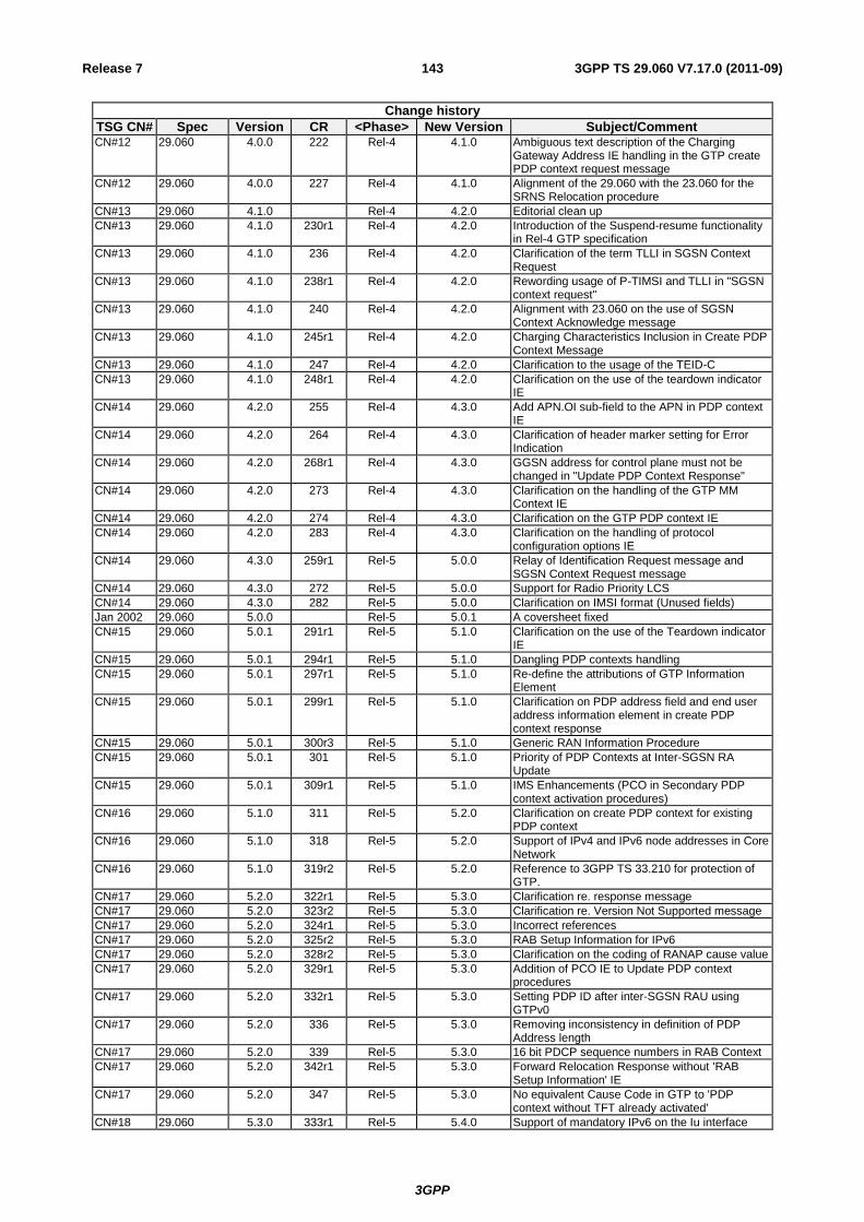
3GPP
3GPP TS 29.060 V7.17.0 (2011-09) 143 Release 7
Change history
TSG CN# Spec Version CR <Phase> New Version Subject/Comment CN#12 29.060 4.0.0 222 Rel-4 4.1.0 Ambiguous text description of the Charging
Gateway Address IE handling in the GTP create PDP context request message
CN#12 29.060 4.0.0 227 Rel-4 4.1.0 Alignment of the 29.060 with the 23.060 for the SRNS Relocation procedure
CN#13 29.060 4.1.0 Rel-4 4.2.0 Editorial clean up
CN#13 29.060 4.1.0 230r1 Rel-4 4.2.0 Introduction of the Suspend-resume functionality in Rel-4 GTP specification
CN#13 29.060 4.1.0 236 Rel-4 4.2.0 Clarification of the term TLLI in SGSN Context Request
CN#13 29.060 4.1.0 238r1 Rel-4 4.2.0 Rewording usage of P-TIMSI and TLLI in "SGSN context request"
CN#13 29.060 4.1.0 240 Rel-4 4.2.0 Alignment with 23.060 on the use of SGSN Context Acknowledge message
CN#13 29.060 4.1.0 245r1 Rel-4 4.2.0 Charging Characteristics Inclusion in Create PDP Context Message
CN#13 29.060 4.1.0 247 Rel-4 4.2.0 Clarification to the usage of the TEID-C
CN#13 29.060 4.1.0 248r1 Rel-4 4.2.0 Clarification on the use of the teardown indicator IE
CN#14 29.060 4.2.0 255 Rel-4 4.3.0 Add APN.OI sub-field to the APN in PDP context IE
CN#14 29.060 4.2.0 264 Rel-4 4.3.0 Clarification of header marker setting for Error Indication
CN#14 29.060 4.2.0 268r1 Rel-4 4.3.0 GGSN address for control plane must not be changed in "Update PDP Context Response"
CN#14 29.060 4.2.0 273 Rel-4 4.3.0 Clarification on the handling of the GTP MM Context IE
CN#14 29.060 4.2.0 274 Rel-4 4.3.0 Clarification on the GTP PDP context IE
CN#14 29.060 4.2.0 283 Rel-4 4.3.0 Clarification on the handling of protocol configuration options IE
CN#14 29.060 4.3.0 259r1 Rel-5 5.0.0 Relay of Identification Request message and SGSN Context Request message
CN#14 29.060 4.3.0 272 Rel-5 5.0.0 Support for Radio Priority LCS
CN#14 29.060 4.3.0 282 Rel-5 5.0.0 Clarification on IMSI format (Unused fields)
Jan 2002 29.060 5.0.0 Rel-5 5.0.1 A coversheet fixed
CN#15 29.060 5.0.1 291r1 Rel-5 5.1.0 Clarification on the use of the Teardown indicator IE
CN#15 29.060 5.0.1 294r1 Rel-5 5.1.0 Dangling PDP contexts handling
CN#15 29.060 5.0.1 297r1 Rel-5 5.1.0 Re-define the attributions of GTP Information Element
CN#15 29.060 5.0.1 299r1 Rel-5 5.1.0 Clarification on PDP address field and end user address information element in create PDP context response
CN#15 29.060 5.0.1 300r3 Rel-5 5.1.0 Generic RAN Information Procedure
CN#15 29.060 5.0.1 301 Rel-5 5.1.0 Priority of PDP Contexts at Inter-SGSN RA Update
CN#15 29.060 5.0.1 309r1 Rel-5 5.1.0 IMS Enhancements (PCO in Secondary PDP context activation procedures)
CN#16 29.060 5.1.0 311 Rel-5 5.2.0 Clarification on create PDP context for existing PDP context
CN#16 29.060 5.1.0 318 Rel-5 5.2.0 Support of IPv4 and IPv6 node addresses in Core Network
CN#16 29.060 5.1.0 319r2 Rel-5 5.2.0 Reference to 3GPP TS 33.210 for protection of GTP.
CN#17 29.060 5.2.0 322r1 Rel-5 5.3.0 Clarification re. response message
CN#17 29.060 5.2.0 323r2 Rel-5 5.3.0 Clarification re. Version Not Supported message
CN#17 29.060 5.2.0 324r1 Rel-5 5.3.0 Incorrect references
CN#17 29.060 5.2.0 325r2 Rel-5 5.3.0 RAB Setup Information for IPv6
CN#17 29.060 5.2.0 328r2 Rel-5 5.3.0 Clarification on the coding of RANAP cause value
CN#17 29.060 5.2.0 329r1 Rel-5 5.3.0 Addition of PCO IE to Update PDP context procedures
CN#17 29.060 5.2.0 332r1 Rel-5 5.3.0 Setting PDP ID after inter-SGSN RAU using GTPv0
CN#17 29.060 5.2.0 336 Rel-5 5.3.0 Removing inconsistency in definition of PDP Address length
CN#17 29.060 5.2.0 339 Rel-5 5.3.0 16 bit PDCP sequence numbers in RAB Context
CN#17 29.060 5.2.0 342r1 Rel-5 5.3.0 Forward Relocation Response without 'RAB Setup Information' IE
CN#17 29.060 5.2.0 347 Rel-5 5.3.0 No equivalent Cause Code in GTP to 'PDP context without TFT already activated'
CN#18 29.060 5.3.0 333r1 Rel-5 5.4.0 Support of mandatory IPv6 on the Iu interface
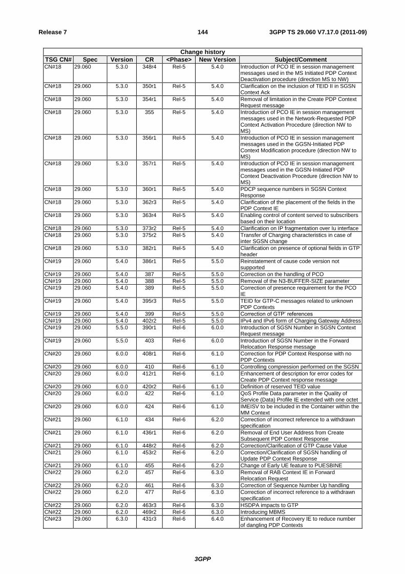
3GPP
3GPP TS 29.060 V7.17.0 (2011-09) 144 Release 7
Change history
TSG CN# Spec Version CR <Phase> New Version Subject/Comment CN#18 29.060 5.3.0 348r4 Rel-5 5.4.0 Introduction of PCO IE in session management
messages used in the MS Initiated PDP Context Deactivation procedure (direction MS to NW)
CN#18 29.060 5.3.0 350r1 Rel-5 5.4.0 Clarification on the inclusion of TEID II in SGSN Context Ack
CN#18 29.060 5.3.0 354r1 Rel-5 5.4.0 Removal of limitation in the Create PDP Context Request message
CN#18 29.060 5.3.0 355 Rel-5 5.4.0 Introduction of PCO IE in session management messages used in the Network-Requested PDP Context Activation Procedure (direction NW to MS)
CN#18 29.060 5.3.0 356r1 Rel-5 5.4.0 Introduction of PCO IE in session management messages used in the GGSN-Initiated PDP Context Modification procedure (direction NW to MS)
CN#18 29.060 5.3.0 357r1 Rel-5 5.4.0 Introduction of PCO IE in session management messages used in the GGSN-Initiated PDP Context Deactivation Procedure (direction NW to MS)
CN#18 29.060 5.3.0 360r1 Rel-5 5.4.0 PDCP sequence numbers in SGSN Context Response
CN#18 29.060 5.3.0 362r3 Rel-5 5.4.0 Clarification of the placement of the fields in the PDP Context IE
CN#18 29.060 5.3.0 363r4 Rel-5 5.4.0 Enabling control of content served to subscribers based on their location
CN#18 29.060 5.3.0 373r2 Rel-5 5.4.0 Clarification on IP fragmentation over Iu interface
CN#18 29.060 5.3.0 375r2 Rel-5 5.4.0 Transfer of Charging characteristics in case of inter SGSN change
CN#18 29.060 5.3.0 382r1 Rel-5 5.4.0 Clarification on presence of optional fields in GTP header
CN#19 29.060 5.4.0 386r1 Rel-5 5.5.0 Reinstatement of cause code version not supported
CN#19 29.060 5.4.0 387 Rel-5 5.5.0 Correction on the handling of PCO
CN#19 29.060 5.4.0 388 Rel-5 5.5.0 Removal of the N3-BUFFER-SIZE parameter
CN#19 29.060 5.4.0 389 Rel-5 5.5.0 Correction of presence requirement for the PCO IE
CN#19 29.060 5.4.0 395r3 Rel-5 5.5.0 TEID for GTP-C messages related to unknown PDP Contexts
CN#19 29.060 5.4.0 399 Rel-5 5.5.0 Correction of GTP‟ references
CN#19 29.060 5.4.0 402r2 Rel-5 5.5.0 IPv4 and IPv6 form of Charging Gateway Address
CN#19 29.060 5.5.0 390r1 Rel-6 6.0.0 Introduction of SGSN Number in SGSN Context Request message
CN#19 29.060 5.5.0 403 Rel-6 6.0.0 Introduction of SGSN Number in the Forward Relocation Response message
CN#20 29.060 6.0.0 408r1 Rel-6 6.1.0 Correction for PDP Context Response with no PDP Contexts
CN#20 29.060 6.0.0 410 Rel-6 6.1.0 Controlling compression performed on the SGSN
CN#20 29.060 6.0.0 412r1 Rel-6 6.1.0 Enhancement of description for error codes for Create PDP Context response message
CN#20 29.060 6.0.0 420r2 Rel-6 6.1.0 Definition of reserved TEID value
CN#20 29.060 6.0.0 422 Rel-6 6.1.0 QoS Profile Data parameter in the Quality of Service (Data) Profile IE extended with one octet
CN#20 29.060 6.0.0 424 Rel-6 6.1.0 IMEISV to be included in the Container within the MM Context
CN#21 29.060 6.1.0 434 Rel-6 6.2.0 Correction of incorrect reference to a withdrawn specification
CN#21 29.060 6.1.0 436r1 Rel-6 6.2.0 Removal of End User Address from Create Subsequent PDP Context Response
CN#21 29.060 6.1.0 448r2 Rel-6 6.2.0 Correction/Clarification of GTP Cause Value CN#21 29.060 6.1.0 453r2 Rel-6 6.2.0 Correction/Clarification of SGSN handling of
Update PDP Context Response CN#21 29.060 6.1.0 455 Rel-6 6.2.0 Change of Early UE feature to PUESBINE CN#22 29.060 6.2.0 457 Rel-6 6.3.0 Removal of RAB Context IE in Forward
Relocation Request
CN#22 29.060 6.2.0 461 Rel-6 6.3.0 Correction of Sequence Number Up handling
CN#22 29.060 6.2.0 477 Rel-6 6.3.0 Correction of incorrect reference to a withdrawn specification
CN#22 29.060 6.2.0 463r3 Rel-6 6.3.0 HSDPA impacts to GTP
CN#22 29.060 6.2.0 469r2 Rel-6 6.3.0 Introducing MBMS
CN#23 29.060 6.3.0 431r3 Rel-6 6.4.0 Enhancement of Recovery IE to reduce number of dangling PDP Contexts

3GPP
3GPP TS 29.060 V7.17.0 (2011-09) 145 Release 7
Change history
TSG CN# Spec Version CR <Phase> New Version Subject/Comment CN#23 29.060 6.3.0 465r3 Rel-6 6.4.0 Controlling the creation of multiple, concurrent
PDP Contexts
CN#23 29.060 6.3.0 480r1 Rel-6 6.4.0 Introduction of the MBMS Support Indication extension header
CN#23 29.060 6.3.0 481r2 Rel-6 6.4.0 Clarification in the definition of the QoS Profile IE encoding
CN#23 29.060 6.3.0 482r1 Rel-6 6.4.0 PDCP and GTP-U sequence numbers received in the PDP Context information element inside SGSN Context Response message
CN#23 29.060 6.3.0 483 Rel-6 6.4.0 Corrections to the Common Flags IE
CN#23 29.060 6.3.0 484 Rel-6 6.4.0 Change to the definition of GTP Tunnel for MBMS
CN#23 29.060 6.3.0 485 Rel-6 6.4.0 Removal of the GGSN address for Contorol Plane in the Delete MBMS Context Request
CN#24 29.060 6.4.0 478r4 Rel-6 6.5.0 Provision of S-CDR information to the GGSN
CN#24 29.060 6.4.0 486r2 Rel-6 6.5.0 Support of Inter-SGSN RA update for MBMS
CN#24 29.060 6.4.0 488r2 Rel-6 6.5.0 Automatic Device Detection (ADD) support in Inter-SGSN Routing Area Update procedures
CN#24 29.060 6.4.0 493 Rel-6 6.5.0 Change the attribution of Radio Priority LCS from TV to TLV
CN#24 29.060 6.4.0 495r1 Rel-6 6.5.0 Addition of BM-SC initiated De-registration
CN#24 29.060 6.4.0 496r1 Rel-6 6.5.0 Addition of TMGI
CN#24 29.060 6.4.0 497 Rel-6 6.5.0 Another Cause for MBMS Notification Reject Request
CN#24 29.060 6.4.0 498r1 Rel-6 6.5.0 Clarification of the Target Identification IE
CN#25 29.060 6.5.0 501 Rel-6 6.6.0 Alignment and enhancement of the "RAT Type" IE
CN#25 29.060 6.5.0 502 Rel-6 6.6.0 Corrections to charging information IEs
CN#25 29.060 6.5.0 507r1 Rel-6 6.6.0 RIM transparent routing
CN#25 29.060 6.5.0 511 Rel-6 6.6.0 Handling of ciphering and integrity keys at inter-SGSN RAU
CN#25 29.060 6.5.0 505 Rel-6 6.6.0 Error Indication during an ongoing MBMS data transfer
CN#25 29.060 6.5.0 506 Rel-6 6.6.0 Addition of Recovery IE in MBMS
CN#25 29.060 6.5.0 510r2 Rel-6 6.6.0 Introduction of a transparent container field for MBMS
CN#25 29.060 6.5.0 512 Rel-6 6.6.0 SGSN Context Request and IMSI
CN#26 29.060 6.6.0 520r1 Rel-6 6.7.0 Additional support of IPv4 and IPv6 node addresses in Create PDP and MBMS context procedures
CN#26 29.060 6.6.0 513r1 Rel-6 6.7.0 Clarification on the usage of the Alternative GGSN Address
CN#26 29.060 6.6.0 514r1 Rel-6 6.7.0 Addition of IEs to MBMS Session Start Request message
CN#26 29.060 6.6.0 515r1 Rel-6 6.7.0 Introduction of MBMS support indication between SGSNs
CN#26 29.060 6.6.0 524 Rel-6 6.7.0 GTP-C tunnel for MBMS broadcast
CN#27 29.060 6.7.0 534r1 Rel-6 6.8.0 Add Source RNC PDCP context info IE in Forward SRNS Context message
CN#27 29.060 6.7.0 470r7 Rel-6 6.8.0 Additional Trace Information
CN#27 29.060 6.7.0 528r2 Rel-6 6.8.0 Clarification to error handling of IEs of type TV
CN#27 29.060 6.7.0 529r1 Rel-6 6.8.0 Introduction of Hop Counter to Identification Request and SGSN Context Request
CN#27 29.060 6.7.0 530 Rel-6 6.8.0 Update of references to charging specifications
CN#27 29.060 6.7.0 531 Rel-6 6.8.0 Providing the BM-SC with approximate UE location information at MBMS context activation
CN#27 29.060 6.7.0 535r1 Rel-6 6.8.0 Clarification of IPv4 and IPv6 node addresses in the SRNS Relocation Procedure.
CN#27 29.060 6.7.0 536r1 Rel-6 6.8.0 Support of IPv4 and IPv6 node addresses in Inter-SGSN RAU procedure
CN#27 29.060 6.7.0 537r1 Rel-6 6.8.0 Add the Common Flags IE to GGSN-Initiated Update PDP Context Request message
CN#27 29.060 6.7.0 538r1 Rel-6 6.8.0 Addition of Selected PLMN-ID for network sharing
CN#27 29.060 6.7.0 539 Rel-6 6.8.0 Correction of type values
CN#27 29.060 6.7.0 540r1 Rel-6 6.8.0 Clarification of PCO IE in Update PDP context response
CN#27 29.060 6.7.0 543r1 Rel-6 6.8.0 Management Based Trace Activation Signalling
CN#27 29.060 6.7.0 544 Rel-6 6.8.0 Addition of RIM Routing Address for GERAN
CN#27 29.060 6.7.0 546r1 Rel-6 6.8.0 Adding missing parameters to the MBMS Session Start Request message
CN#27 29.060 6.7.0 547r1 Rel-6 6.8.0 Enhanced NSAPI for MBMS
CN#27 29.060 6.7.0 549 Rel-6 6.8.0 Change of newly added IEs in Rel 6 to type TLV
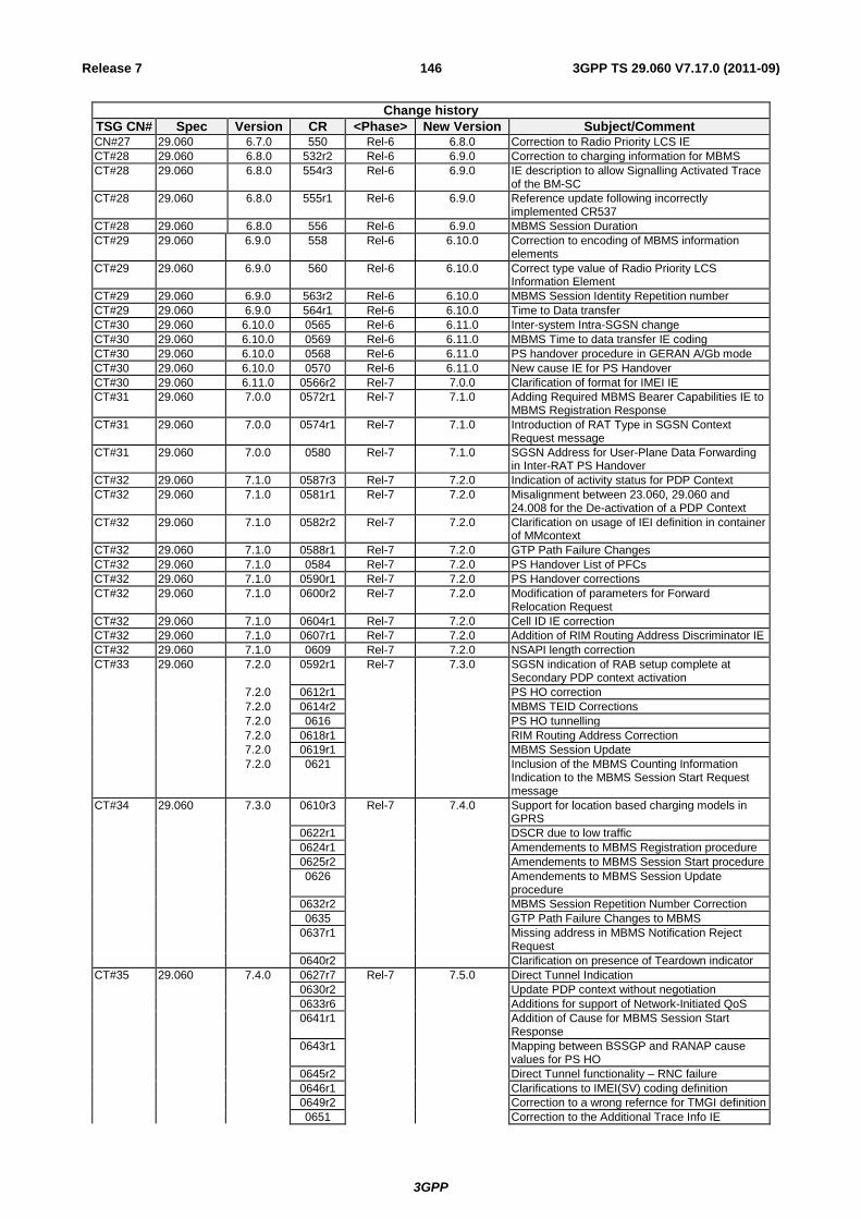
3GPP
3GPP TS 29.060 V7.17.0 (2011-09) 146 Release 7
Change history
TSG CN# Spec Version CR <Phase> New Version Subject/Comment CN#27 29.060 6.7.0 550 Rel-6 6.8.0 Correction to Radio Priority LCS IE
CT#28 29.060 6.8.0 532r2 Rel-6 6.9.0 Correction to charging information for MBMS
CT#28 29.060 6.8.0 554r3 Rel-6 6.9.0 IE description to allow Signalling Activated Trace of the BM-SC
CT#28 29.060 6.8.0 555r1 Rel-6 6.9.0 Reference update following incorrectly implemented CR537
CT#28 29.060 6.8.0 556 Rel-6 6.9.0 MBMS Session Duration
CT#29 29.060 6.9.0 558 Rel-6 6.10.0 Correction to encoding of MBMS information elements
CT#29 29.060 6.9.0 560 Rel-6 6.10.0 Correct type value of Radio Priority LCS Information Element
CT#29 29.060 6.9.0 563r2 Rel-6 6.10.0 MBMS Session Identity Repetition number
CT#29 29.060 6.9.0 564r1 Rel-6 6.10.0 Time to Data transfer
CT#30 29.060 6.10.0 0565 Rel-6 6.11.0 Inter-system Intra-SGSN change
CT#30 29.060 6.10.0 0569 Rel-6 6.11.0 MBMS Time to data transfer IE coding
CT#30 29.060 6.10.0 0568 Rel-6 6.11.0 PS handover procedure in GERAN A/Gb mode
CT#30 29.060 6.10.0 0570 Rel-6 6.11.0 New cause IE for PS Handover
CT#30 29.060 6.11.0 0566r2 Rel-7 7.0.0 Clarification of format for IMEI IE
CT#31 29.060 7.0.0 0572r1 Rel-7 7.1.0 Adding Required MBMS Bearer Capabilities IE to MBMS Registration Response
CT#31 29.060 7.0.0 0574r1 Rel-7 7.1.0 Introduction of RAT Type in SGSN Context Request message
CT#31 29.060 7.0.0 0580 Rel-7 7.1.0 SGSN Address for User-Plane Data Forwarding in Inter-RAT PS Handover
CT#32 29.060 7.1.0 0587r3 Rel-7 7.2.0 Indication of activity status for PDP Context
CT#32 29.060 7.1.0 0581r1 Rel-7 7.2.0 Misalignment between 23.060, 29.060 and 24.008 for the De-activation of a PDP Context
CT#32 29.060 7.1.0 0582r2 Rel-7 7.2.0 Clarification on usage of IEI definition in container of MMcontext
CT#32 29.060 7.1.0 0588r1 Rel-7 7.2.0 GTP Path Failure Changes
CT#32 29.060 7.1.0 0584 Rel-7 7.2.0 PS Handover List of PFCs
CT#32 29.060 7.1.0 0590r1 Rel-7 7.2.0 PS Handover corrections
CT#32 29.060 7.1.0 0600r2 Rel-7 7.2.0 Modification of parameters for Forward Relocation Request
CT#32 29.060 7.1.0 0604r1 Rel-7 7.2.0 Cell ID IE correction
CT#32 29.060 7.1.0 0607r1 Rel-7 7.2.0 Addition of RIM Routing Address Discriminator IE
CT#32 29.060 7.1.0 0609 Rel-7 7.2.0 NSAPI length correction
CT#33 29.060 7.2.0 0592r1 Rel-7 7.3.0 SGSN indication of RAB setup complete at Secondary PDP context activation
7.2.0 0612r1 PS HO correction
7.2.0 0614r2 MBMS TEID Corrections
7.2.0 0616 PS HO tunnelling
7.2.0 0618r1 RIM Routing Address Correction
7.2.0 0619r1 MBMS Session Update
7.2.0 0621 Inclusion of the MBMS Counting Information Indication to the MBMS Session Start Request message
CT#34 29.060 7.3.0 0610r3 Rel-7 7.4.0 Support for location based charging models in GPRS
0622r1 DSCR due to low traffic
0624r1 Amendements to MBMS Registration procedure
0625r2 Amendements to MBMS Session Start procedure
0626 Amendements to MBMS Session Update procedure
0632r2 MBMS Session Repetition Number Correction
0635 GTP Path Failure Changes to MBMS
0637r1 Missing address in MBMS Notification Reject Request
0640r2 Clarification on presence of Teardown indicator
CT#35 29.060 7.4.0 0627r7 Rel-7 7.5.0 Direct Tunnel Indication
0630r2 Update PDP context without negotiation
0633r6 Additions for support of Network-Initiated QoS
0641r1 Addition of Cause for MBMS Session Start Response
0643r1 Mapping between BSSGP and RANAP cause values for PS HO
0645r2 Direct Tunnel functionality – RNC failure
0646r1 Clarifications to IMEI(SV) coding definition
0649r2 Correction to a wrong refernce for TMGI definition
0651 Correction to the Additional Trace Info IE

3GPP
3GPP TS 29.060 V7.17.0 (2011-09) 147 Release 7
Change history
TSG CN# Spec Version CR <Phase> New Version Subject/Comment 0652 Correction of reserved bits
March 2003
29.060 7.5.0 7.5.1 The Error Indication (EI) moved into 7.7.81. Tables and figures information removed.
CT#36 29.060 7.5.1 0648r2 Rel-7 7.6.0 Correction to the length of the MBMS Session Duration IE
0654 Correction to the APN IE definition
0655r1 Usage of Echo Request / Response for MBMS
0658 Error Indications between RNC and GGSN in the case of Direct Tunnelling
0659r2 NSAPI in Create PDP Context Response
CT#37 29.060 7.6.0 0662r1 Rel-7 7.7.0 TFT in Initiate PDP Context Activation Request message
0663 QoS Extension
0667r1 PDP contexts with upwards QoS negotiation
0669 Target Identification encoding
0670 Correction to the User Location Information procedure
CT#38 29.060 7.7.0 0675r1 Rel-7 7.8.0 Specification Update of GBR and MBR due to MIMO
0676r2 Aligning GTPv1 spec with Rel-7 RAN specs on RNC merged with NodeB feature
0679 Direct Tunnel Correction
CT#39 29.060 7.8.0 0683 Rel-7 7.9.0 Correction of location reporting
CT#40 29.060 7.9.0 0685 Rel-7 7.10.0 Essential correction to the Initiate PDP Context Activation Response message
CT#41 29.060 7.10.0 0689 Rel-7 7.11.0 MBMS Reject
0691 Changes due to bearer mapping for NRSPCA
0695r1 Clarification on the format of TMGI
CT#42 29.060 7.11.0 0698 Rel-7 7.12.0 Essential correction to RAT Type handling in Update PDP Context Request message
CT#44 29.060 7.12.0 0708r1 Rel-7 7.13.0 IE Ordering in MBMS Session Start Request
CT#45 7.13.0 0715 Rel-7 7.14.0 P-TMSI Signature for Suspend Request
0717r1 Clarifications to DT functionality
CT#46 29.060 7.14.0 0732r2 Rel-7 7.15.0 Addition of “Reliable INTER RAT PS HANDOVER” indicator
CT#52 29.060 7.15.0 0820r1 Rel-7 7.16.0 Incorrect PCO handling at the GGSN
CT#53 29.060 7.16.0 0826r1 Rel-7 7.17.0 PCO handling at the GGSN for pre-Rel 7 SGSNs