2014 brazed plate heat exchangers for fluid power … plate heat exchangers for fluid power...
TRANSCRIPT

thermaltransfer.com [email protected]
Brazed Plate Heat Exchangers for Fluid Power Applications BPSeries
2014
We COOL what you POWER
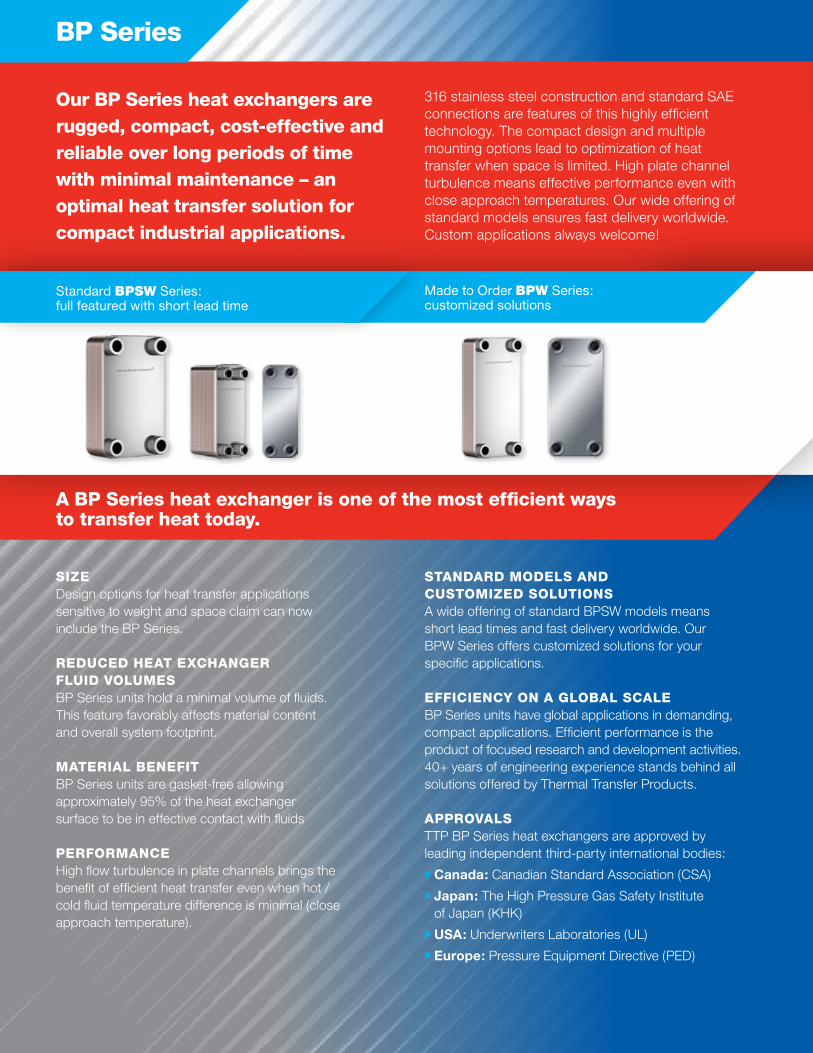
BP Series
A BP Series heat exchanger is one of the most efficient ways to transfer heat today.
SizEDesign options for heat transfer applications sensitive to weight and space claim can now include the BP Series.
REduCEd hEAt ExChAngER fLuid vOLumESBP Series units hold a minimal volume of fluids. This feature favorably affects material content and overall system footprint.
mAtERiAL BEnEfitBP Series units are gasket-free allowing approximately 95% of the heat exchanger surface to be in effective contact with fluids
PERfORmAnCEHigh flow turbulence in plate channels brings the benefit of efficient heat transfer even when hot / cold fluid temperature difference is minimal (close approach temperature).
StAndARd mOdELS And CuStOmizEd SOLutiOnSA wide offering of standard BPSW models means short lead times and fast delivery worldwide. Our BPW Series offers customized solutions for your specific applications.
EffiCiEnCy On A gLOBAL SCALE BP Series units have global applications in demanding, compact applications. Efficient performance is the product of focused research and development activities. 40+ years of engineering experience stands behind all solutions offered by Thermal Transfer Products.
APPROvALSTTP BP Series heat exchangers are approved by leading independent third-party international bodies:
n Canada: Canadian Standard Association (CSA)
n Japan: The High Pressure Gas Safety Institute of Japan (KHK)
n USA: Underwriters Laboratories (UL)
n Europe: Pressure Equipment Directive (PED)
Made to Order BPW Series:customized solutions
316 stainless steel construction and standard SAE connections are features of this highly efficient technology. The compact design and multiple mounting options lead to optimization of heat transfer when space is limited. High plate channel turbulence means effective performance even with close approach temperatures. Our wide offering of standard models ensures fast delivery worldwide. Custom applications always welcome!
Our BP Series heat exchangers are rugged, compact, cost-effective and reliable over long periods of time with minimal maintenance – an optimal heat transfer solution for compact industrial applications.
Standard BPSW Series: full featured with short lead time
1
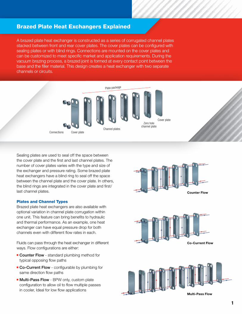
Plate package
Connections Cover plateChannel plates
Zero hole channel plate
Cover plate
Brazed Plate heat Exchangers Explained
A brazed plate heat exchanger is constructed as a series of corrugated channel plates stacked between front and rear cover plates. The cover plates can be configured with sealing plates or with blind rings. Connections are mounted on the cover plates and can be customized to meet specific market and application requirements. During the vacuum brazing process, a brazed joint is formed at every contact point between the base and the filler material. This design creates a heat exchanger with two separate channels or circuits.
Co-Current Flow
Counter Flow
Multi-Pass Flow
Sealing plates are used to seal off the space between the cover plate and the first and last channel plates. The number of cover plates varies with the type and size of the exchanger and pressure rating. Some brazed plate heat exchangers have a blind ring to seal off the space between the channel plate and the cover plate. In others, the blind rings are integrated in the cover plate and first/last channel plates.
Plates and Channel typesBrazed plate heat exchangers are also available with optional variation in channel plate corrugation within one unit. This feature can bring benefits to hydraulic and thermal performance. As an example, one heat exchanger can have equal pressure drop for both channels even with different flow rates in each.
Fluids can pass through the heat exchanger in different ways. Flow configurations are either:
n Counter Flow - standard plumbing method for typical opposing flow paths
n Co-Current Flow - configurable by plumbing for same direction flow paths
n Multi-Pass Flow - BPW only, custom plate configuration to allow oil to flow multiple passes in cooler, Ideal for low flow applications
www.thermaltransfer.com For technical assistance & pricing, email [email protected]
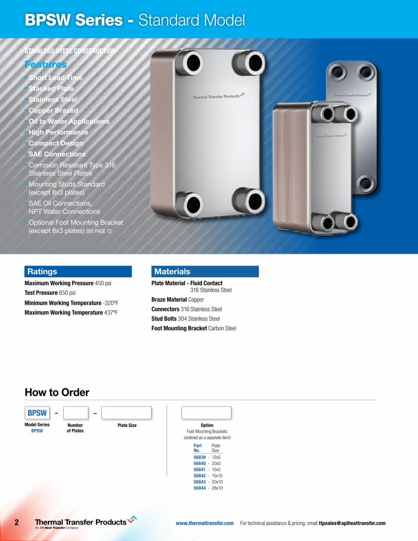
RatingsMaximum Working Pressure 450 psi
Test Pressure 650 psi
Minimum Working Temperature -320ºF
Maximum Working Temperature 437ºF
BPSW Series - Standard Model
MaterialsPlate Material - Fluid Contact
316 Stainless Steel
Braze Material Copper
Connectors 316 Stainless Steel
Stud Bolts 304 Stainless Steel
Foot Mounting Bracket Carbon Steel
STainleSS STeel ConSTruCTion
featuresn Short Lead Timen Stacked Platen Stainless Steeln Copper Brazedn Oil to Water Applicationsn High Performancen Compact Designn SAE Connectionsn Corrosion Resistant Type 316
Stainless Steel Platesn Mounting Studs Standard
(except 8x3 plates)n SAE Oil Connections,
NPT Water Connectionsn Optional Foot Mounting Bracket
(except 8x3 plates) See page 13
How to Order
number of Plates
–
Model SeriesBPSW
Plate Size
–
optionFoot Mounting Brackets
(ordered as a separate item)
Part Plateno. Size
56839 - 12x556840 - 20x556841 - 15x556842 - 15x1056843 - 20x1056844 - 28x10
BPSW
3www.thermaltransfer.com For technical assistance & pricing, email [email protected]
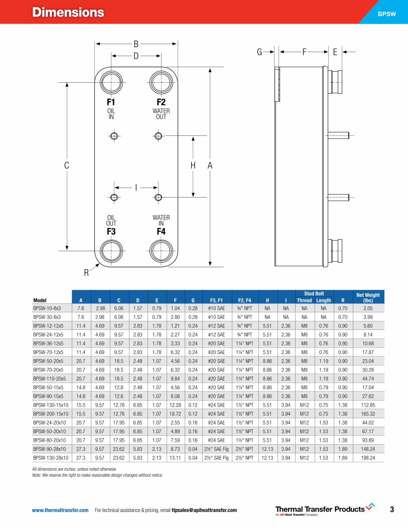
BPSWdimensions
F1 F2
F3 F4
OILOUT
WATERIN
OILIN
WATEROUT
D G EB
F
C
R
AH
I
Model a B C D e F G F3, F1 F2, F4 H iStud Bolt
rnet Weight
(lbs)Thread lengthBPSW-10-8x3 7.6 2.98 6.06 1.57 0.79 1.04 0.28 #10 SAE ¾" NPT NA NA NA NA 0.70 2.05
BPSW-30-8x3 7.6 2.98 6.06 1.57 0.79 2.80 0.28 #10 SAE ¾" NPT NA NA NA NA 0.70 3.99
BPSW-12-12x5 11.4 4.69 9.57 2.83 1.78 1.21 0.24 #12 SAE ¾" NPT 5.51 2.36 M8 0.76 0.90 5.60
BPSW-24-12x5 11.4 4.69 9.57 2.83 1.78 2.27 0.24 #12 SAE ¾" NPT 5.51 2.36 M8 0.76 0.90 8.14
BPSW-36-12x5 11.4 4.69 9.57 2.83 1.78 3.33 0.24 #20 SAE 1¼" NPT 5.51 2.36 M8 0.76 0.90 10.68
BPSW-70-12x5 11.4 4.69 9.57 2.83 1.78 6.32 0.24 #20 SAE 1¼" NPT 5.51 2.36 M8 0.76 0.90 17.87
BPSW-50-20x5 20.7 4.69 18.5 2.48 1.07 4.56 0.24 #20 SAE 1¼" NPT 8.86 2.36 M8 1.19 0.90 23.04
BPSW-70-20x5 20.7 4.69 18.5 2.48 1.07 6.32 0.24 #20 SAE 1¼" NPT 8.86 2.36 M8 1.19 0.90 30.28
BPSW-110-20x5 20.7 4.69 18.5 2.48 1.07 9.84 0.24 #20 SAE 1¼" NPT 8.86 2.36 M8 1.19 0.90 44.74
BPSW-50-15x5 14.8 4.69 12.6 2.48 1.07 4.56 0.24 #20 SAE 1¼" NPT 8.86 2.36 M8 0.79 0.90 17.04
BPSW-90-15x5 14.8 4.69 12.6 2.48 1.07 8.08 0.24 #20 SAE 1¼" NPT 8.86 2.36 M8 0.79 0.90 27.62
BPSW-130-15x10 15.5 9.57 12.76 6.85 1.07 12.28 0.12 #24 SAE 1½" NPT 5.51 3.94 M12 0.75 1.38 112.85
BPSW-200-15x10 15.5 9.57 12.76 6.85 1.07 18.72 0.12 #24 SAE 1½" NPT 5.51 3.94 M12 0.75 1.38 165.32
BPSW-24-20x10 20.7 9.57 17.95 6.85 1.07 2.55 0.16 #24 SAE 1½" NPT 5.51 3.94 M12 1.53 1.38 44.02
BPSW-50-20x10 20.7 9.57 17.95 6.85 1.07 4.89 0.16 #24 SAE 1½" NPT 5.51 3.94 M12 1.53 1.38 67.17
BPSW-80-20x10 20.7 9.57 17.95 6.85 1.07 7.59 0.16 #24 SAE 1½" NPT 5.51 3.94 M12 1.53 1.38 93.89
BPSW-90-28x10 27.3 9.57 23.62 5.83 2.13 8.73 0.04 2½" SAE Flg 2½" NPT 12.13 3.94 M12 1.53 1.89 148.24
BPSW-130-28x10 27.3 9.57 23.62 5.83 2.13 13.11 0.04 2½" SAE Flg 2½" NPT 12.13 3.94 M12 1.53 1.89 198.24
All dimensions are inches, unless noted otherwise. Note: We reserve the right to make reasonable design changes without notice.
www.thermaltransfer.com For technical assistance & pricing, email [email protected]
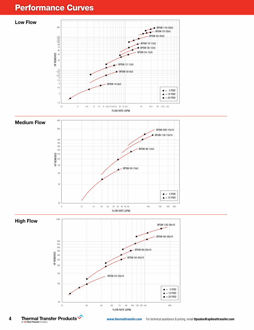
Performance Curves
Low Flow
Medium Flow
High Flow
Small Flow Applications
HP R
EMOV
ED
300
150135120105
9075
60
45
30
1513.5
1210.5
97.5
6
4.5
3
1.5
1.5
FLOW RATE (GPM)
22.5 45 67.5 90 112.5 1353 4.5 6 7.5 9 10.5 12 13.5 15 18 21
BPSW-10-8x3
BPSW-30-8x3
BPSW-12-12x5
BPSW-24-12x5
BPSW-36-12x5
BPSW-70-12x5
BPSW-50-20x5
BPSW-70-20x5BPSW-110-20x5
= 5 PSID= 10 PSID= 20 PSID
Medium Flow Applications
HP R
EMOV
ED
400
300
200
180
160
140
120
100
80
60
40
20
5 10 15 20 25 30 35 40 45 50 100 150 200 350
FLOW RATE (GPM)
BPSW-50-15x5
BPSW-90-15x5
BPSW-130-15x10
BPSW-200-15x10
= 5 PSID= 10 PSID
Large Flow Applications
HP R
EMOV
ED
1000
500
450
400
350
300
250
200
150
100
50
15 30 45 60 75 90 105 120 135 150 300
FLOW RATE (GPM)
BPSW-24-20x10
BPSW-50-20x10
BPSW-80-20x10
BPSW-90-28x10
BPSW-130-28x10
= 5 PSID= 10 PSID= 20 PSID
5www.thermaltransfer.com For technical assistance & pricing, email [email protected]
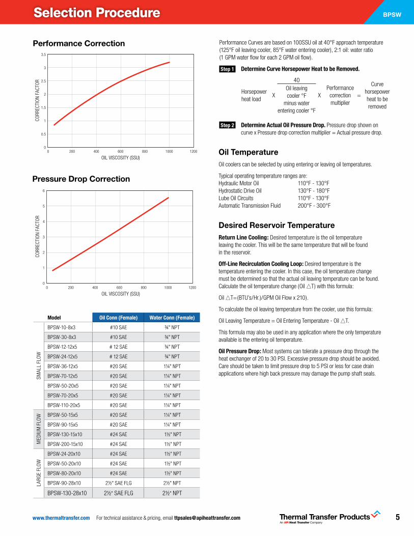
Model oil Conn (Female) Water Conn (Female)
SMAL
L FL
OW
BPSW-10-8x3 #10 SAE ¾" NPT
BPSW-30-8x3 #10 SAE ¾" NPT
BPSW-12-12x5 # 12 SAE ¾" NPT
BPSW-24-12x5 # 12 SAE ¾" NPT
BPSW-36-12x5 #20 SAE 1¼" NPT
BPSW-70-12x5 #20 SAE 1¼" NPT
BPSW-50-20x5 #20 SAE 1¼" NPT
BPSW-70-20x5 #20 SAE 1¼" NPT
BPSW-110-20x5 #20 SAE 1¼" NPT
MED
IUM
FLO
W BPSW-50-15x5 #20 SAE 1¼" NPT
BPSW-90-15x5 #20 SAE 1¼" NPT
BPSW-130-15x10 #24 SAE 1½" NPT
BPSW-200-15x10 #24 SAE 1½" NPT
LARG
E FL
OW
BPSW-24-20x10 #24 SAE 1½" NPT
BPSW-50-20x10 #24 SAE 1½" NPT
BPSW-80-20x10 #24 SAE 1½" NPT
BPSW-90-28x10 2½" SAE FLG 2½" NPT
BPSW-130-28x10 2½" SAE FLG 2½" NPT
BPSWSelection Procedure
Performance Curves are based on 100SSU oil at 40°F approach temperature (125°F oil leaving cooler, 85°F water entering cooler), 2:1 oil: water ratio (1 GPM water flow for each 2 GPM oil flow).
Step 1 Determine Curve Horsepower Heat to be removed.
Step 2 Determine actual oil Pressure Drop. Pressure drop shown on curve x Pressure drop correction multiplier = Actual pressure drop.
Performance Correction FactorsCO
RREC
TIO
N FA
CTO
R
3.5
3
2.5
2
1.5
1
0.5
00 200 400 600 800 1000 1200
OIL VISCOSITY (SSU)
Performance Correction
Presure Drop Correction Factors
CORR
ECTI
ON
FACT
OR
6
5
4
3
2
1
00 200 400 600 800 1000 1200
OIL VISCOSITY (SSU)
Pressure Drop Correction
Oil TemperatureOil coolers can be selected by using entering or leaving oil temperatures.
Typical operating temperature ranges are: Hydraulic Motor Oil 110°F - 130°F Hydrostatic Drive Oil 130°F - 180°F Lube Oil Circuits 110°F - 130°F Automatic Transmission Fluid 200°F - 300°F
Desired Reservoir Temperaturereturn line Cooling: Desired temperature is the oil temperature leaving the cooler. This will be the same temperature that will be found in the reservoir.
off-line recirculation Cooling loop: Desired temperature is the temperature entering the cooler. In this case, the oil temperature change must be determined so that the actual oil leaving temperature can be found. Calculate the oil temperature change (Oil #T) with this formula:
Oil #T=(BTU’s/Hr.)/GPM Oil Flow x 210).
To calculate the oil leaving temperature from the cooler, use this formula:
Oil Leaving Temperature = Oil Entering Temperature - Oil #T.
This formula may also be used in any application where the only temperature available is the entering oil temperature.
oil Pressure Drop: Most systems can tolerate a pressure drop through the heat exchanger of 20 to 30 PSI. Excessive pressure drop should be avoided. Care should be taken to limit pressure drop to 5 PSI or less for case drain applications where high back pressure may damage the pump shaft seals.
Horsepowerheat load
40Oil leavingcooler °F
minus waterentering cooler °F
Performancecorrectionmultiplier
Curvehorsepowerheat to beremoved
X X =
www.thermaltransfer.com For technical assistance & pricing, email [email protected]
Please see pages 8-9 for all possible connection sizes and types.
Note: Connections on the cooler must all be the same height. Cannot use connections of different heights.
BPW Series - Made to Order Model
STainleSS STeel ConSTruCTion
featuresn Customizable sizes
and optionsn Stacked Platen Stainless Steeln Copper Brazedn High Performancen Compact Designn Corrosion Resistant Type 316
Stainless Steel Platesn Mounting Studs Standard
(except 8x3 plates)n Optional Foot Mounting Bracket
(except 8x3 plates) See page 13
How to Order
Model Size Selected8x312x520x515x515x1020x1028x10
ConnectionF3
–
number of Plates
– –
Model SeriesBPW
BPWConnection
F1
–
ConnectionF2
–
ConnectionF4
–
optionFoot Mounting Brackets
(ordered as a separate item)
F2F1
F3F4
RatingsMaximum Working Pressure 450 psi
Test Pressure 650 psi
Minimum Working Temperature -320ºF
Maximum Working Temperature 437ºF at 450 psi
Pressure rating is for copper brazed only. Consult factory for alternatives.
MaterialsPlate Material - Fluid Contact
316 Stainless Steel
Braze Material Copper Nickel Optional
Connectors 316 Stainless Steel
Stud Bolts 304 Stainless Steel
Foot Mounting Bracket Carbon Steel
Part Plateno. Size
56839 - 12x556840 - 20x556841 - 15x556842 - 15x1056843 - 20x1056844 - 28x10

7www.thermaltransfer.com For technical assistance & pricing, email [email protected]
BPWdimensions
Model a B C D e F G H iStud Bolt
rapproximate Weight (lbs)Thread length
BPW-NoP-8x3 7.6 2.98 6.06 1.57
See Connection
Tables
0.157 + 0.088 x NoP 0.28 NA NA NA NA 0.70 1.082 + 0.097 x NoP
BPW-NoP-12x5 11.4 4.69 9.57 2.83 0.157 + 0.088 x NoP 0.24 5.51 2.36 M8 0.79 0.90 3.058 + 0.21 x NoP
BPW-NoP-20x5 20.7 4.69 18.50 2.48 0.157 + 0.088 x NoP 0.24 8.86 2.36 M8 1.19 0.90 4.967 + 0.362 x NoP
BPW-NoP-15x5 14.8 4.69 12.60 2.48 0.157 + 0.088 x NoP 0.24 8.86 2.36 M8 0.79 0.90 3.814 + 0.265 x NoP
BPW-NoP-15x10 15.5 9.57 12.76 6.85 0.315 + 0.092 x NoP 0.12 5.51 3.94 M12 0.75 1.38 15.41 + 0.75 x NoP
BPW-NoP-20x10 20.7 9.57 17.95 6.85 0.394 + 0.090 x NoP 0.16 5.51 3.94 M12 1.53 1.38 22.641 + 0.891 x NoP
BPW-NoP-28x10 27.3 9.57 23.54 5.83 0.630 + 0.096 x NoP 0.04 12.13 3.94 M12 1.53 1.89 35.741 + 1.25 x NoP
NoP = Number of PlatesAll dimensions are inches, unless noted otherwise. Note: We reserve the right to make reasonable design changes without notice.
F1 F2
F3 F4
OILOUT
WATERIN
OILIN
WATEROUT
D G EB
F
C
R
AH
I
www.thermaltransfer.com For technical assistance & pricing, email [email protected]
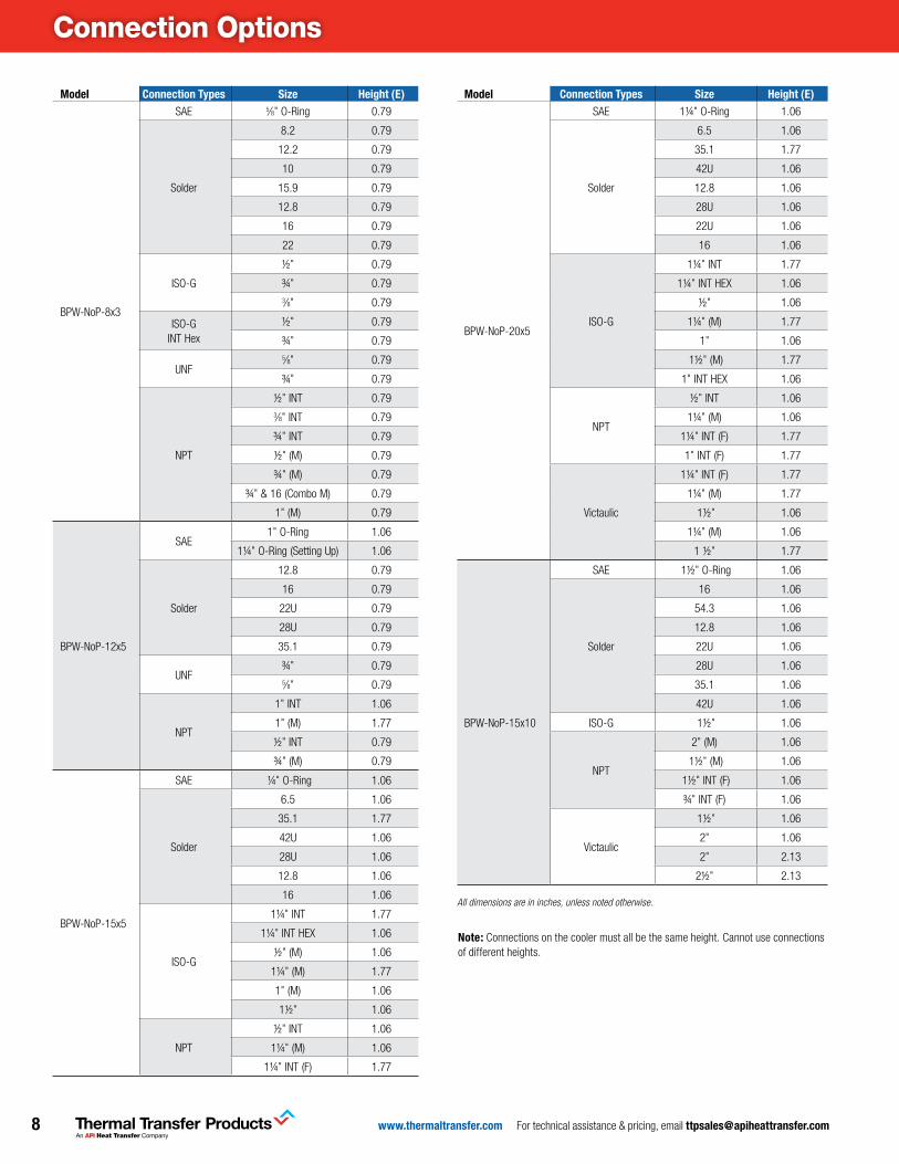
Connection Options
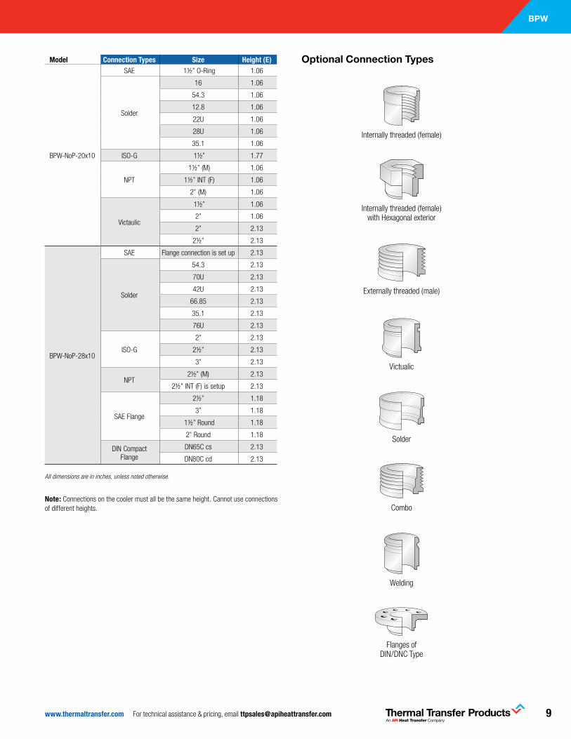
Model Connection Types Size Height (e)
BPW-NoP-8x3
SAE 5⁄8" O-Ring 0.79
Solder
8.2 0.79
12.2 0.79
10 0.79
15.9 0.79
12.8 0.79
16 0.79
22 0.79
ISO-G
½" 0.79
¾" 0.793⁄8" 0.79
ISO-G INT Hex
½" 0.79
¾" 0.79
UNF5⁄8" 0.79
¾" 0.79
NPT
½" INT 0.793⁄8" INT 0.79
¾" INT 0.79
½" (M) 0.79
¾" (M) 0.79
¾" & 16 (Combo M) 0.79
1" (M) 0.79
BPW-NoP-12x5
SAE1" O-Ring 1.06
1¼" O-Ring (Setting Up) 1.06
Solder
12.8 0.79
16 0.79
22U 0.79
28U 0.79
35.1 0.79
UNF¾" 0.795⁄8" 0.79
NPT
1" INT 1.06
1" (M) 1.77
½" INT 0.79
¾" (M) 0.79
BPW-NoP-15x5
SAE ¼" O-Ring 1.06
Solder
6.5 1.06
35.1 1.77
42U 1.06
28U 1.06
12.8 1.06
16 1.06
ISO-G
1¼" INT 1.77
1¼" INT HEX 1.06
½" (M) 1.06
1¼" (M) 1.77
1" (M) 1.06
1½" 1.06
NPT
½" INT 1.06
1¼" (M) 1.06
1¼" INT (F) 1.77
Model Connection Types Size Height (e)
BPW-NoP-20x5
SAE 1¼" O-Ring 1.06
Solder
6.5 1.06
35.1 1.77
42U 1.06
12.8 1.06
28U 1.06
22U 1.06
16 1.06
ISO-G
1¼" INT 1.77
1¼" INT HEX 1.06
½" 1.06
1¼" (M) 1.77
1" 1.06
1½" (M) 1.77
1" INT HEX 1.06
NPT
½" INT 1.06
1¼" (M) 1.06
1¼" INT (F) 1.77
1" INT (F) 1.77
Victaulic
1¼" INT (F) 1.77
1¼" (M) 1.77
1½" 1.06
1¼" (M) 1.06
1 ½" 1.77
BPW-NoP-15x10
SAE 1½" O-Ring 1.06
Solder
16 1.06
54.3 1.06
12.8 1.06
22U 1.06
28U 1.06
35.1 1.06
42U 1.06
ISO-G 1½" 1.06
NPT
2" (M) 1.06
1½" (M) 1.06
1½" INT (F) 1.06
¾" INT (F) 1.06
Victaulic
1½" 1.06
2" 1.06
2" 2.13
2½" 2.13
All dimensions are in inches, unless noted otherwise.
note: Connections on the cooler must all be the same height. Cannot use connections of different heights.
9www.thermaltransfer.com For technical assistance & pricing, email [email protected]
BPW
Welding
Model Connection Types Size Height (e)
BPW-NoP-20x10
SAE 1½" O-Ring 1.06
Solder
16 1.06
54.3 1.06
12.8 1.06
22U 1.06
28U 1.06
35.1 1.06
ISO-G 1½" 1.77
NPT
1½" (M) 1.06
1½" INT (F) 1.06
2" (M) 1.06
Victaulic
1½" 1.06
2" 1.06
2" 2.13
2½" 2.13
BPW-NoP-28x10
SAE Flange connection is set up 2.13
Solder
54.3 2.13
70U 2.13
42U 2.13
66.85 2.13
35.1 2.13
76U 2.13
ISO-G
2" 2.13
2½" 2.13
3" 2.13
NPT2½" (M) 2.13
2½" INT (F) is setup 2.13
SAE Flange
2½" 1.18
3" 1.18
1½" Round 1.18
2" Round 1.18
DIN Compact Flange
DN65C cs 2.13
DN80C cd 2.13
All dimensions are in inches, unless noted otherwise.
Optional Connection Types
Internally threaded (female)
Externally threaded (male)
Solder
Flanges of DIN/DNC Type
Combo
Victualic
Internally threaded (female) with Hexagonal exterior
note: Connections on the cooler must all be the same height. Cannot use connections of different heights.
www.thermaltransfer.com For technical assistance & pricing, email [email protected]
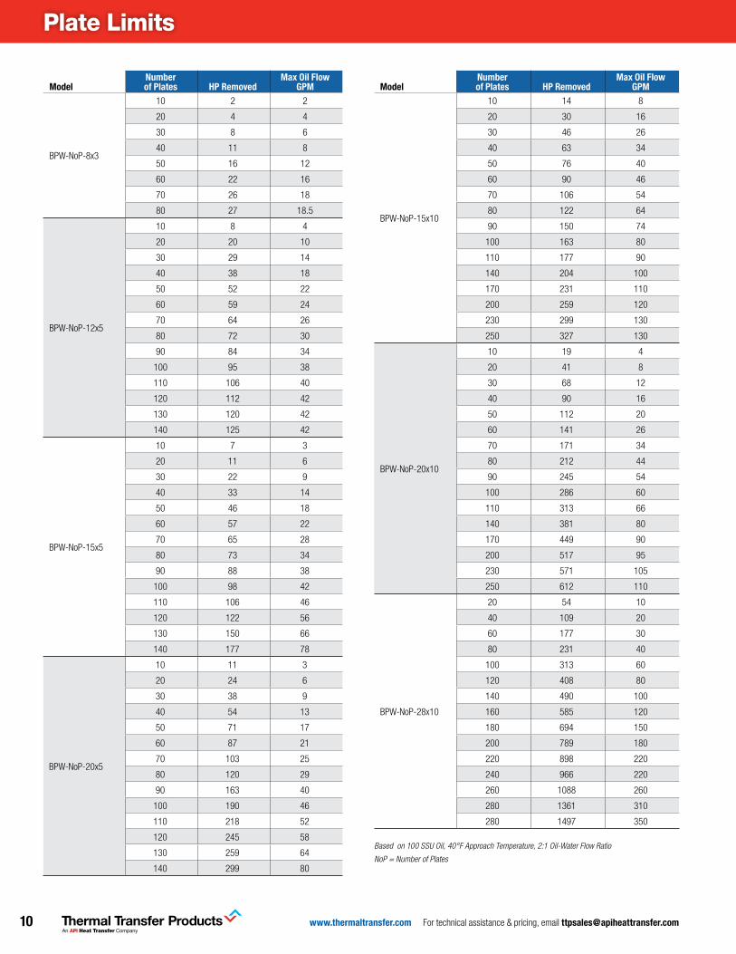
Plate Limits
Modelnumber of Plates HP removed
Max oil Flow GPM
BPW-NoP-8x3
10 2 2
20 4 4
30 8 6
40 11 8
50 16 12
60 22 16
70 26 18
80 27 18.5
BPW-NoP-12x5
10 8 4
20 20 10
30 29 14
40 38 18
50 52 22
60 59 24
70 64 26
80 72 30
90 84 34
100 95 38
110 106 40
120 112 42
130 120 42
140 125 42
BPW-NoP-15x5
10 7 3
20 11 6
30 22 9
40 33 14
50 46 18
60 57 22
70 65 28
80 73 34
90 88 38
100 98 42
110 106 46
120 122 56
130 150 66
140 177 78
BPW-NoP-20x5
10 11 3
20 24 6
30 38 9
40 54 13
50 71 17
60 87 21
70 103 25
80 120 29
90 163 40
100 190 46
110 218 52
120 245 58
130 259 64
140 299 80
Modelnumber of Plates HP removed
Max oil Flow GPM
BPW-NoP-15x10
10 14 8
20 30 16
30 46 26
40 63 34
50 76 40
60 90 46
70 106 54
80 122 64
90 150 74
100 163 80
110 177 90
140 204 100
170 231 110
200 259 120
230 299 130
250 327 130
BPW-NoP-20x10
10 19 4
20 41 8
30 68 12
40 90 16
50 112 20
60 141 26
70 171 34
80 212 44
90 245 54
100 286 60
110 313 66
140 381 80
170 449 90
200 517 95
230 571 105
250 612 110
BPW-NoP-28x10
20 54 10
40 109 20
60 177 30
80 231 40
100 313 60
120 408 80
140 490 100
160 585 120
180 694 150
200 789 180
220 898 220
240 966 220
260 1088 260
280 1361 310
280 1497 350
Based on 100 SSU Oil, 40°F Approach Temperature, 2:1 Oil-Water Flow Ratio
NoP = Number of Plates
11www.thermaltransfer.com For technical assistance & pricing, email [email protected]
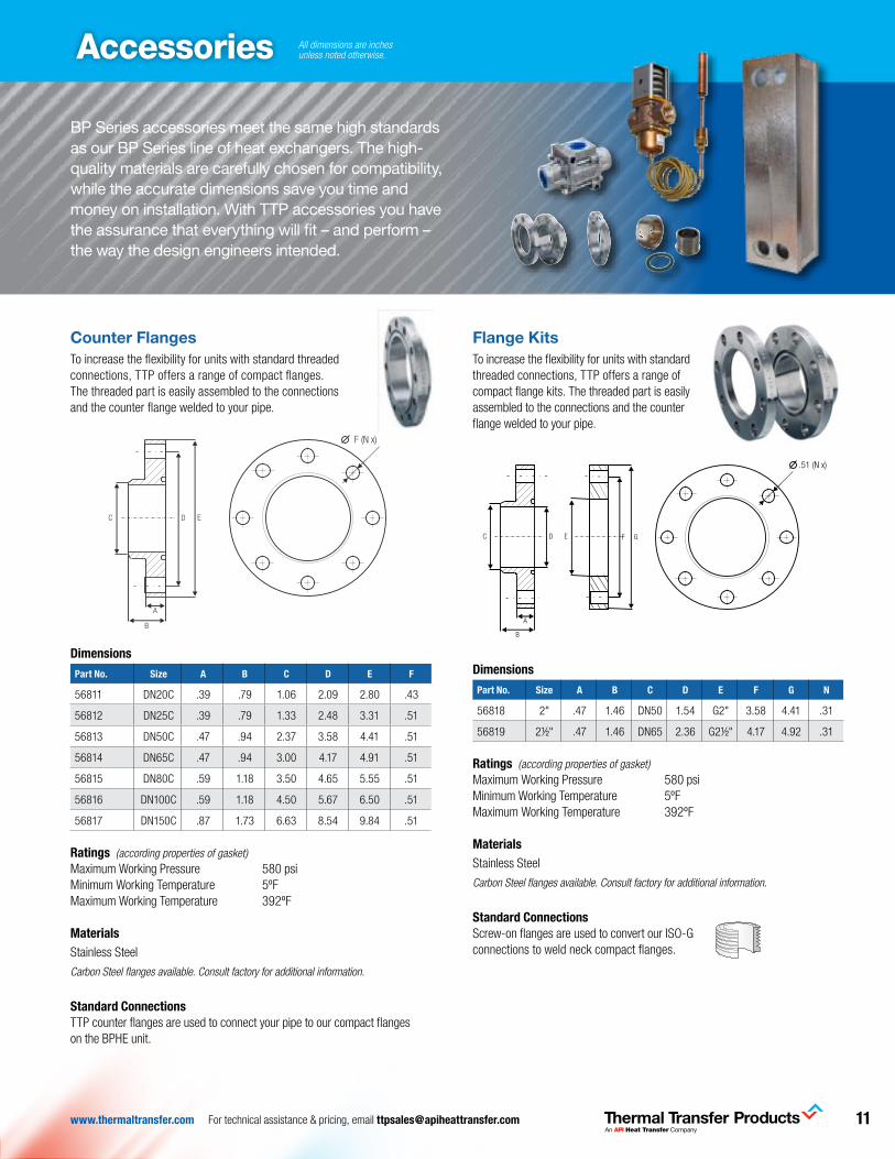
Counter FlangesTo increase the flexibility for units with standard threaded connections, TTP offers a range of compact flanges. The threaded part is easily assembled to the connections and the counter flange welded to your pipe.
Dimensions
Part no. Size a B C D e F
56811 DN20C .39 .79 1.06 2.09 2.80 .43
56812 DN25C .39 .79 1.33 2.48 3.31 .51
56813 DN50C .47 .94 2.37 3.58 4.41 .51
56814 DN65C .47 .94 3.00 4.17 4.91 .51
56815 DN80C .59 1.18 3.50 4.65 5.55 .51
56816 DN100C .59 1.18 4.50 5.67 6.50 .51
56817 DN150C .87 1.73 6.63 8.54 9.84 .51
ratings (according properties of gasket)Maximum Working Pressure 580 psiMinimum Working Temperature 5ºFMaximum Working Temperature 392ºF
Materials Stainless Steel
Carbon Steel flanges available. Consult factory for additional information.
Standard ConnectionsTTP counter flanges are used to connect your pipe to our compact flanges on the BPHE unit.
Accessories
BP Series accessories meet the same high standards as our BP Series line of heat exchangers. The high-quality materials are carefully chosen for compatibility, while the accurate dimensions save you time and money on installation. With TTP accessories you have the assurance that everything will fit – and perform – the way the design engineers intended.
Flange KitsTo increase the flexibility for units with standard threaded connections, TTP offers a range of compact flange kits. The threaded part is easily assembled to the connections and the counter flange welded to your pipe.
Dimensions
Part no. Size a B C D e F G n
56818 2" .47 1.46 DN50 1.54 G2" 3.58 4.41 .31
56819 2½" .47 1.46 DN65 2.36 G2½" 4.17 4.92 .31
ratings (according properties of gasket)Maximum Working Pressure 580 psiMinimum Working Temperature 5ºFMaximum Working Temperature 392ºF
Materials Stainless Steel
Carbon Steel flanges available. Consult factory for additional information.
Standard ConnectionsScrew-on flanges are used to convert our ISO-G connections to weld neck compact flanges.
Dimensions
Technical data*
Max working temperature 200°CMin working temperature -15°CMax working pressure 40 bar
*According properties of SWEP gasket
Standard connectionsSWEP screw-on flanges are used to convert our ISO-G connections to weld neck DN Compac flanges
CF Compac flange kits
Material options
Stainless steel: 1.4404 alt. 1.4571Carbon steel: C22.8
Size A (mm) B (mm) C D (mm) E F (mm) G (mm) N
2" 12 37 DN50 39,0 G2" 91 112 8
2 1/2" 12 37 DN65 60,0 G2 1/2" 106 125 8
B
A
DC
13 (N x)
E F G
.51 (N x)
For additional information please contact your local SWEP representative.SWEP reserves the right to make changes without prior notice
Size A B C D E Ø F
DN20C 10 20 26,9 53 71 11
DN25C 10 20 33,7 63 84 13
DN50C 12 24 60,3 91 112 13
DN65C 12 24 76,1 106 125 13
DN80C 15 30 88,9 118 141 13
DN100C 15 30 114,3 144 165 13
DN150C 22 44 168.3 217 250 13
Dimensions
Technical data*
Max working temperature 200°CMin working temperature -15°CMax working pressure 40 bar
* According properties of SWEP gasket
B
A
DC E
Standard connectionsSWEP counter flanges are used to connect your pipe to our DN compac flanges on the BPHE unit.
CF Compac counter flanges
www .swep .net
Material options
Stainless steel: 1.4404 alt. 1.4571Carbon steel: C22.8
F (N x)
All dimensions are inches unless noted otherwise.
www.thermaltransfer.com For technical assistance & pricing, email [email protected]
Accessories
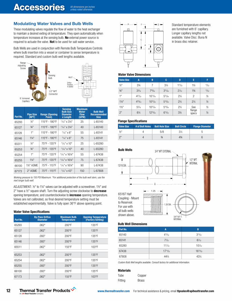
Modulating Water Valves and Bulb Wells These modulating valves regulate the flow of water to the heat exchanger to maintain a desired exiting oil temperature. They open automatically when temperature increases at the sensing bulb. no external power source is required to actuate the valve. not to be used for salt water service.
Bulb Wells are used in conjunction with Remote Bulb Temperature Controls where bulb insertion into a vessel or container to sense temperature is required. Standard and custom bulb well lengths available.
RangeAdjusting
Screw
6' ArmoredCapillary
SensingBulb
1/2" NPTConnector
INLET
OrficePosition,if stalled
Part no.Pipe Size
(nPT)range (opening
Point)
Sensing Bulb SizeDiameterx length
Maximum Water Flow
(GPM)
Bulb Well recommended
Size
65293 ½" 115°F - 180°F 11⁄16" x 3¼" 25 L-65140
65127 ¾" 115°F - 180°F 11⁄16" x 3¼" 40 L-65140
65128 1" 115°F - 180°F 11⁄16" x 6" 55 L-65141
65146 1¼" 115°F - 180°F 11⁄16" x 6" 75 L-65141
65511 ½" 75°F - 135°F 11⁄16" x 10" 25 L-65280
65253 ¾" 75°F - 135°F 11⁄16" x 10" 40 L-65280
65254 1" 75°F - 135°F 11⁄16" x 16¼" 55 L-67438
65255 1¼" 75°F - 135°F 11⁄16" x 16¼" 75 L-67438
66100 1½" ASME 75°F - 115°F 11⁄16" x 16¼" 90 L-67438
67173 2" ASME 75°F - 115°F 11⁄16" x 43" 150 L-67808
Working pressure to 150 PSI Maximum. *For additional protection of the bulb well stem, use the next longer bulb well.
ADJUSTMENT: ½" to 1¼" valves can be adjusted with a screwdriver, 1½" and 2" have a ½" square shaft. Turn the adjusting screw clockwise to decrease opening temperature; and counterclockwise to increase opening temperature. Valves are not calibrated, so final desired temperature setting must be established experimentally. Valve is fully open 36°F above opening point.
Standard temperature elements are furnished with 6’ capillary. Longer capillary lengths not available. Valve Disc: Buna N in brass disc retainer.
A
C
A D
E
F
Flange Specifications
Valve Size # of Bolt Holes Bolt Hole Size Bolt Circle Flange Diameter
½" 4 5/8 37⁄8 5
2" 4 ¾ 4¾ 6
Water Valve Dimensions
Valve Size a B C D e F
½" 3¼ 7 33⁄8 127⁄32 1½ 12⁄32
¾" 39⁄16 729⁄64 351⁄64 21⁄32 1¾ 12⁄32
1" 427⁄32 1013⁄16 531⁄64 25⁄8 2 ½
1¼" 455⁄64 1037⁄64 543⁄64 25⁄8 23⁄8 ½
1½" 55⁄16 1037⁄64 543⁄64 25⁄8 See flange specs
½
2" 65⁄8 1233⁄64 615⁄32 3½ ½
Bulb Wells
65187 Half Coupling - Mount to Reservoir. For use with all bulb wells shown above.
1.25
1.38 DIA.
3/4" N.P.T. INTERNAL
3/4" NPT EXTERNAL
1/2" NPT INTERNAL
13/16 DIA.
B
A
Bulb Well Dimensions
Part no. a B
65140 415⁄32 315⁄32
65141 77⁄32 67⁄32
65280 117⁄32 107⁄32
67438 1715⁄32 1615⁄32
67808 443⁄8 433⁄8
Custom Bulb Well lengths available. Consult factory for additional information.
Materials Tube Copper
Fitting Brass
Water Valve Specifications
Part no.By-Pass orifice
DiameterMaximum Bulb Temperature
opening Temperature (Factory Setting)
65293 .062" 200°F 135°F
65127 .062" 200°F 135°F
65128 .093" 200°F 135°F
65146 .093" 200°F 135°F
65511 .062" 155°F 103°F
65253 .062" 200°F 135°F
65254 .062" 200°F 135°F
65255 .093" 200°F 135°F
66100 .093" 200°F 135°F
67173 .062" 155°F 103°F
All dimensions are inches unless noted otherwise.

13www.thermaltransfer.com For technical assistance & pricing, email [email protected]
Accessories
COSD Connection for soldering
A B C
D
E
H
The used gasket has a thickness of 2 mm
Union nut MS58
Soldering sleeve Rg5
Gasket Hecker-Centellen WS 3820
F
G
For additional information please cont act your local SWEP representative.SWEP reserves the right to make changes without prior notice
Technical dat a (in mm)
Nominal A B C D E F G H Opening ofdiameter the sp anner
3/4” 21,8 18 24,0 17 3,0 13 15 16 30
1” 26,0 22 30,0 19 3,0 15 19 17 36
1 1/4” 35,0 28 38,5 25 3,0 20 25 18 46
2” 48,3 42 56,0 32 4,0 26 39 24 65
2 ½” 60,0 54 72,0 37 4,8 31 51 26 85
Material
COSD Connection for SolderingFor standard thread-connections of TTP BPHE, the welding sleeve with union nut can be used to connect pipes with the connection of the heat exchanger. According to the quality of the used medium, the welding sleeve can be chosen in carbon or stainless steel. The soldering connection consists of a union nut, a gasket and a soldering sleeve. COSD connections are suitable for refrigerant applications.
Dimensions
Part no.nominaldiameter a B C D e F G H
opening of the
spanner
56831 ¾" .86 .71 .94 .67 .12 .57 .59 .63 1.18
56832 1" 1.02 .87 1.18 .75 .12 .59 .75 .67 1.42
56833 1¼" 1.38 1.10 1.52 .98 .12 .79 .98 .71 1.81
56834 2" 1.90 1.65 2.20 1.26 .16 1.02 1.54 .94 2.56
56835 2½" 2.36 1.13 2.83 1.46 .19 1.22 2.00 1.02 3.35
The used gasket has a thickness of .079" (2mm)
Materials Union nut MS58
Soldering sleeve Rg5
Gasket Hecker-Centellen WS 3820
Water Strainers
Dimensions
Part no.a
nPT B C D e
65294 3⁄8 3.08 2.52 1.88 ¼
65295 ½ 3.08 2.52 1.88 ¼
65296 ¾ 3.87 3.07 2.32 ¼
65297 1 4.44 3.77 2.81 3⁄8
65301 1¼ 5.25 4.32 3.18 3⁄8
65302 1½ 6.25 5.10 3.77 ½
65303 2 7.63 6.25 4.65 ½
rating Maximum Working Pressure 300 psi
Materials Housing Bronze
Screen 20 Mesh, 304 Stainless Steel Wire
AInlet & Outlet Pipe Thread
ECleanout Opening Pipe Thread
AB
CD
B
A
.50
C
GD
E
H4 PLACES
90˚±5˚
Part no.
PlateSize a B C D e G H
56839 12x5 7.99 9.35 3.15 7.17 1.77 0.69 .40 x .59
56840 20x5 7.99 15.65 3.15 7.17 1.77 0.69 .40 x .59
56841 15x5 7.99 12.74 3.15 7.17 1.77 0.69 .40 x .59
56842 15x10 13.20 12.40 3.94 12.40 2.64 0.65 .40 x .75
56843 20x10 13.51 14.37 3.94 12.72 2.64 0.65 .40 x .75
56844 28x10 13.20 21.30 3.94 12.40 2.64 0.65 .40 x .75
All dimensions are in inches, unless noted otherwise.
Mounting bracket for location purposes only. Bracket is not designed to support entire weight of the cooler. Customer to add extra support if necessary.
Mounting BracketOptional Foot Mounting Bracket (except 8x3 plates). Constructed of Carbon Steel.
All dimensions are inches unless noted otherwise.
www.thermaltransfer.com For technical assistance & pricing, email [email protected]
Accessories
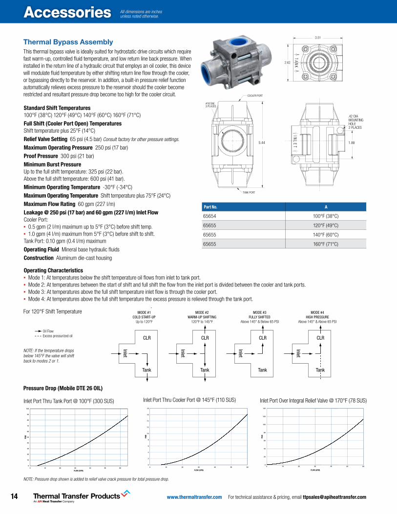
Thermal Bypass Assembly This thermal bypass valve is ideally suited for hydrostatic drive circuits which require fast warm-up, controlled fluid temperature, and low return line back pressure. When installed in the return line of a hydraulic circuit that employs an oil cooler, this device will modulate fluid temperature by either shifting return line flow through the cooler, or bypassing directly to the reservoir. In addition, a built-in pressure relief function automatically relieves excess pressure to the reservoir should the cooler become restricted and resultant pressure drop become too high for the cooler circuit.
Standard Shift Temperatures 100°F (38°C) 120°F (49°C) 140°F (60°C) 160°F (71°C)
Full Shift (Cooler Port open) Temperatures Shift temperature plus 25°F (14°C)
relief Valve Setting 65 psi (4.5 bar) Consult factory for other pressure settings.
Maximum operating Pressure 250 psi (17 bar)
Proof Pressure 300 psi (21 bar)
Minimum Burst PressureUp to the full shift temperature: 325 psi (22 bar).Above the full shift temperature: 600 psi (41 bar).
Minimum operating Temperature -30°F (-34°C)
Maximum operating Temperature Shift temperature plus 75°F (24°C)
Maximum Flow rating 60 gpm (227 l/m)
leakage @ 250 psi (17 bar) and 60 gpm (227 l/m) inlet FlowCooler Port: ▪ 0.5 gpm (2 l/m) maximum up to 5°F (3°C) before shift temp.▪ 1.0 gpm (4 l/m) maximum from 5°F (3°C) before shift to shift.Tank Port: 0.10 gpm (0.4 l/m) maximum
operating Fluid Mineral base hydraulic fluids
Construction Aluminum die-cast housing
THERMAL BYPASS VALVE 65655
5.44
#16 SAE3 PLACES
COOLER PORT
TANK PORT
1.88
.42 DIA
2 PLACES
THERMAL BYPASS VALVE 65655
TE
LNI
MOUNTINGHOLE
2.62
3.51
THERMAL BYPASS VALVE 65655K
NA
T
Part no. a
65654 100°F (38°C)
65655 120°F (49°C)
65655 140°F (60°C)
65655 160°F (71°C)
Pressure Drop (Mobile DTe 26 oil)
Inlet Port Thru Cooler Port @ 145°F (110 SUS)
PSID
FLOW (GPM)
INLET PORT THRU COOLER PORT @ 145 DEG F(63 DEG C) (110 SUS)
0
2
4
6
8
10
12
14
16
18
0 10 20 30 40 50 60
Inlet Port Thru Tank Port @ 100°F (300 SUS)
PSID
FLOW (GPM)
INLET PORT THRU TANK PORT @ 100 DEG F (38 DEG C) (300 SUS)
0
10
20
30
40
50
60
70
80
90
100
0 10 20 30 40 50 60
Inlet Port Over Integral Relief Valve @ 170°F (78 SUS)
PSID
FLOW (GPM)
*INLET PORT OVER INTEGRAL RELIEF VALVE @ 170 DEG F (77 DEG C ) (78SUS)
0
20
40
60
80
100
120
140
0 10 20 30 40 50 60
NOTE: Pressure drop shown is added to relief valve crack pressure for total pressure drop.
For 120° F Shift Temperature
CLR
Tank
Inlet
CLR
Tank
Inlet
CLR
Tank
Inlet
CLR
Tank
Inlet
MODE #1COLD START-UP
MODE #2WARM-UP SHIFTING
MODE #3FULLY SHIFTED
MODE #4HIGH PRESSURE
Up to 120°F 120°F to 145°F Above 145° & Below 65 PSI Above 145° & Above 65 PSI
KEYOil FlowExcess pressurized oil
NOTE: If the temperature drops below 145°F the valve will shift back to modes 2 or 1.
operating Characteristics ▪ Mode 1: At temperatures below the shift temperature oil flows from inlet to tank port.▪ Mode 2: At temperatures between the start of shift and full shift the flow from the inlet port is divided between the cooler and tank ports.▪ Mode 3: At temperatures above the full shift temperature inlet flow is through the cooler port.▪ Mode 4: At temperatures above the full shift temperature the excess pressure is relieved through the tank port.
For 120°F Shift Temperature
For 120° F Shift Temperature
CLR
Tank
Inlet
CLR
Tank
Inlet
CLR
Tank
Inlet
CLR
Tank
Inlet
MODE #1COLD START-UP
MODE #2WARM-UP SHIFTING
MODE #3FULLY SHIFTED
MODE #4HIGH PRESSURE
Up to 120°F 120°F to 145°F Above 145° & Below 65 PSI Above 145° & Above 65 PSI
KEYOil FlowExcess pressurized oil
All dimensions are inches unless noted otherwise.
15www.thermaltransfer.com For technical assistance & pricing, email [email protected]
Accessories
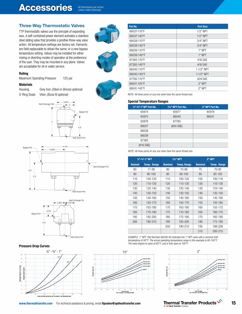
Three-Way Thermostatic ValvesTTP thermostatic valves use the principle of expanding wax. A self-contained power element activates a stainless steel sliding valve that provides a positive three-way valve action. All temperature settings are factory set. Elements are field replaceable to obtain the same, or a new bypass temperature setting. Valves may be installed for either mixing or diverting modes of operation at the preference of the user. They may be mounted in any plane. Valves are acceptable for oil or water service.
rating Maximum Operating Pressure 125 psi
Materials Housing Grey Iron (Steel or Bronze optional)
O-Ring Seals Viton (Buna N optional)
Part no. Port Size
66037-110°F 1/2" NPT
66037-140°F 1/2" NPT
66038-110°F 3/4" NPT
66038-140°F 3/4" NPT
66039-110°F 1" NPT
66039-140°F 1" NPT
67365-110°F #16 SAE
67365-140°F #16 SAE
66040-110°F 1-1/2" NPT
66040-140°F 1-1/2" NPT
67760-110°F #24 SAE
66041-105°F 2" NPT
66041-140°F 2" NPT
NOTE: All three ports on any one valve have the same thread size.
Special Temperature ranges
½"-¾"-1" nPT Part no. 1½" nPT Part no. 2" nPT Part no.
65974 65977 65978
65975 66040 66041
65976 67760
66037 (#24 SAE)
66038
66039
67365
(#16 SAE)
NOTE: All three ports on any one valve have the same thread size.
½"-¾"-1" nPT 1½" nPT 2" nPT
nominal Temp. range nominal Temp. range nominal Temp. range
80 77-88 80 70-88 75 70-85
90 80-100 90 80-100 90 85-105
110 100-120 110 100-120 105 100-116
120 110-130 120 110-130 120 110-130
130 120-140 130 120-140 130 124-140
140 130-150 140 130-150 140 135-150
150 140-160 150 140-160 150 145-160
160 150-170 160 150-170 155 150-165
170 163-180 170 163-180 160 155-172
185 175-190 175 170-185 165 160-175
195 185-200 180 175-190 170 165-180
200 190-210 190 185-200 180 175-190
200 190-210 195 188-208
210 200-215
EXAMPLE: 1" NPT, Part Number 66039-90 indicates the 1" NPT valve with a nominal shift temperature of 90°F. The actual operating temperature range in this example is 80-100°F. The valve begins to open at 80°F, and is fully open at 100°F.
PRES
SURE
DRO
P OI
L @
150
SSU
PRES
SURE
DRO
P W
ATER
FLOW (US GPM) WATER/OIL NOT TO EXCEED 7 PSI PRESSURE DROP
FLOW (US GPM) NOT TO EXCEED 7 PSI PRESSURE DROP
PRES
SURE
DRO
P (P
SI)
SAE 40 @ 140°F
SAE 30@ 140°F
SAE 40 @ 180°F
SAE 30 @ 180°F
WATER
PRES
SURE
DRO
P (P
SI)
FLOW (US GPM) NOT TO EXCEED 7 PSI PRESSURE DROP
SAE 40 @ 140°F
SAE 30@ 140°F
SAE 40 @ 180°F
SAE 30 @ 180°F
WATER
Pressure Drop Curves
½" - ¾" - 1" 1½" 2"
3.625
4.25
2
6
C
B
A
Heat Exchanger Port
Heat Source Port
Bypass Port
6.1253.0625
5.25
CB
A
Bypass Port
Heat Source Port
Heat Exchanger Port
3.75
9.75
C
B
A
Heat Exchanger Port
Heat Source Port
Bypass Port3.8125
3.5625 2.875
3.625
4.25
2
6
C
B
A
Heat Exchanger Port
Heat Source Port
Bypass Port
6.1253.0625
5.25
CB
A
Bypass Port
Heat Source Port
Heat Exchanger Port
3.75
9.75
C
B
A
Heat Exchanger Port
Heat Source Port
Bypass Port3.8125
3.5625 2.875
3.625
4.25
2
6
C
B
A
Heat Exchanger Port
Heat Source Port
Bypass Port
6.1253.0625
5.25
CB
A
Bypass Port
Heat Source Port
Heat Exchanger Port
3.75
9.75
C
B
A
Heat Exchanger Port
Heat Source Port
Bypass Port3.8125
3.5625 2.875
All dimensions are inches unless noted otherwise.
www.thermaltransfer.com For technical assistance & pricing, email [email protected]
Accessories installation & maintenance
GENERAL INFORMATION
Depending on material combinations, pressure ratings and functions, there are several different types of compact Brazed Plate Heat Exchangers (BPHEs). The standard materials are stainless steel, vacuum-brazed with a pure copper or nickel-based filler.
The basic materials of construction indicate the type of fluids that TTP’s BPHEs can be used with. Typical examples are: synthetic or mineral oil, organic solvents, water (not seawater), glycol mixtures (ethylene and propylene glycol).
The front plate of TTP’s BPHE is marked with an arrow. The purpose of this marker is to indicate the front side of the BPHE and the location of the inner and outer circuits/channels. With the arrow pointing up, the left side (Port F1, F3) is the inner circuit and the right side (Port F2, F4) is the outer circuit. For TTP asymmetric products one circuit is narrow while the other is wide, which makes it additionally important to correctly combine flow and circuit to reach design performance.
Ports F1/F2/F3/F4 are situated on the front of the heat exchanger.
DESIGN CONDITIONS
The standard pressure rating used for TTP BPHEs, i.e. for standard operating pressure, is maximum 450 psi (3.1 MPa). TTP offers a wide range of pressure ratings based on applications, from low pressures (116 psi) up to high pressures (2030 psi). TTP’s standard maximum operating temperature is 437°F for copper-brazed BPHEs, and 660°F for Nickel brazed BPHEs. However, as temperature and pressure are closely coupled, there is a possibility to increase the pressure if the temperature is reduced. For details, please check the label and other technical documentation.
F2F1
F3F4
InsulationInsulation boxes for heating applications.
PU 20 Insulation
For additional information please contact your local SWEP representative.SWEP reserves the right to make changes without prior notice
Technical data
Max working temperature +150°CThermal conductivity 0.023 W/mKFire properties B2 in accordance with DIN 4102 Color Silver colored cover
Size 5T 8T 10T/12 15 16
A mm 237 362 333 500 422B mm 120 121 162 115 164F mm* approx. 32,0+2,3xNP 33,0+2,3xNP 51,0+2,4xNP 32,0+2,3xNP 54,0+2,2xNPG mm 30 30 50 30 50Thickness mm 20 20 20 20 20 *Only available in selected 20th NP (for example 20, 40, 60, etc). NP = Number of Plates
Dimensions
Size 26 25T/28/80 35 120T/50/56 57
A mm 422 572 439 572 572B mm 164 164 288 288 288F mm* approx. 55+1,6xNP 55,0+2,2xNP 48,0+2,4xNP 54,0+2,5xNP 68,0+2,4xNP G mm 50 50 60 90 90 Thickness mm 20 20 20 20 20 *Only available in selected 20th NP (for example 20, 40, 60, etc). NP = Number of Plates
Size 60
A mm 420B mm 409F mm* approx. 56,0+2,2xNPG mm 90Thickness mm 20 *Only available in selected 20th NP (for example 20, 40, 60, etc). NP = Number of Plates
www.swep.net
SWEP accessories meet the same high standards as the company's BPHEs. They are produced according to SWEP's specification by rigorously selected suppliers. The high-quality materials are carefully chosen for compatibility, while the accurate dimensions save you time and money on install-ation.
With SWEP accessories you have the assurance that everything will fit and perform the way the design engineers intended.
For more information, please contact your local SWEP representative or visit us at www.swep.net.
Material
Insulation: Polyurethane rigid foamInsulation cover: Aluminium
A
B
A
C
D
Dimensions
Part no. a B C* (approx.) D Thickness
56820 9.33 4.72 1.26 + .09 x NoP 1.18 .79
56821 13.11 6.38 2.00 + .09 x NoP 1.97 .79
56822 16.61 6.46 2.13 + .09 x NoP 1.97 .79
56823 16.61 6.46 2.17 + .09 x NoP 1.97 .79
56825 17.28 11.34 2.17 + .10 x NoP 3.54 .79
56826 22.52 11.34 2.68 + .09 x NoP 3.54 .79
56827 22.52 11.34 2.17 +. 10 x NoP 3.54 .79
*Only available in selected 20th NoP (20, 40, 60, etc). NoP = Number of Plates.
rating Maximum Working Temperature 302°F Thermal Conductivity 0.013 BTU/HrFtF° Fire Properties B2 in accordance with DIN 4102 Color Silver
Materials Insulation Polyurethane rigid foamInsulation Cover Aluminum
PU 20 Insulation
For additional information please contact your local SWEP representative.SWEP reserves the right to make changes without prior notice
Technical data
Max working temperature +150°CThermal conductivity 0.023 W/mKFire properties B2 in accordance with DIN 4102 Color Silver colored cover
Size 5T 8T 10T/12 15 16
A mm 237 362 333 500 422B mm 120 121 162 115 164F mm* approx. 32,0+2,3xNP 33,0+2,3xNP 51,0+2,4xNP 32,0+2,3xNP 54,0+2,2xNPG mm 30 30 50 30 50Thickness mm 20 20 20 20 20 *Only available in selected 20th NP (for example 20, 40, 60, etc). NP = Number of Plates
Dimensions
Size 26 25T/28/80 35 120T/50/56 57
A mm 422 572 439 572 572B mm 164 164 288 288 288F mm* approx. 55+1,6xNP 55,0+2,2xNP 48,0+2,4xNP 54,0+2,5xNP 68,0+2,4xNP G mm 50 50 60 90 90 Thickness mm 20 20 20 20 20 *Only available in selected 20th NP (for example 20, 40, 60, etc). NP = Number of Plates
Size 60
A mm 420B mm 409F mm* approx. 56,0+2,2xNPG mm 90Thickness mm 20 *Only available in selected 20th NP (for example 20, 40, 60, etc). NP = Number of Plates
www.swep.net
SWEP accessories meet the same high standards as the company's BPHEs. They are produced according to SWEP's specification by rigorously selected suppliers. The high-quality materials are carefully chosen for compatibility, while the accurate dimensions save you time and money on install-ation.
With SWEP accessories you have the assurance that everything will fit and perform the way the design engineers intended.
For more information, please contact your local SWEP representative or visit us at www.swep.net.
Material
Insulation: Polyurethane rigid foamInsulation cover: Aluminium
A
B
A
C
D
Dimensions
Part no. a B C* (approx.) D Thickness
56828 26.78 18.11 9.13 + .09 x NoP 3.15 1.97
56829 37.80 17.32 9.84 + .10 x NoP 3.35 1.97
56830 27.95 18.90 10.24 + .09 x NoP 3.74 1.97
*Only available in selected 20th NoP (20, 40, 60, etc). NoP = Number of Plates.
rating Maximum Working Temperature 302°F Thermal Conductivity 0.014 BTU/HrFtF° Fire Properties B2 in accordance with DIN 4102 Color Silver
Materials Insulation Rigid expanded polyurethaneInsulation Cover Aluminum
Please read carefully before attempting to assemble, install, operate or maintain the product described. Protect yourself and others by observing all safety information. Retain instruction for future reference.
All dimensions are inches unless noted otherwise.
17www.thermaltransfer.com For technical assistance & pricing, email [email protected]
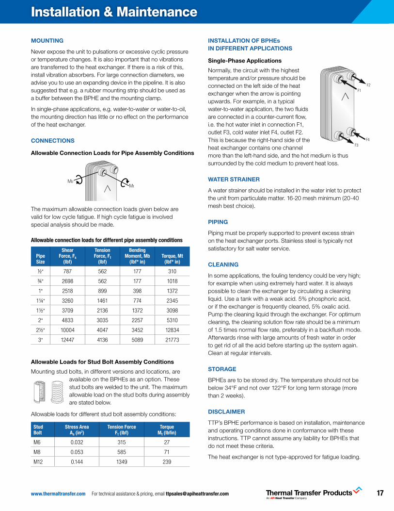
installation & maintenance
MOUNTING
Never expose the unit to pulsations or excessive cyclic pressure or temperature changes. It is also important that no vibrations are transferred to the heat exchanger. If there is a risk of this, install vibration absorbers. For large connection diameters, we advise you to use an expanding device in the pipeline. It is also suggested that e.g. a rubber mounting strip should be used as a buffer between the BPHE and the mounting clamp.
In single-phase applications, e.g. water-to-water or water-to-oil, the mounting direction has little or no effect on the performance of the heat exchanger.
CONNECTIONS
Allowable Connection Loads for Pipe Assembly Conditions
The maximum allowable connection loads given below are valid for low cycle fatigue. If high cycle fatigue is involved special analysis should be made.
allowable connection loads for different pipe assembly conditions
Pipe Size
Shear Force, Fs
(lbf)
Tension Force, Ft
(lbf)
Bending Moment, Mb
(lbf* in)Torque, Mt
(lbf* in)
½" 787 562 177 310
¾" 2698 562 177 1018
1" 2518 899 398 1372
1¼" 3260 1461 774 2345
1½" 3709 2136 1372 3098
2" 4833 3035 2257 5310
2½" 10004 4047 3452 12834
3" 12447 4136 5089 21773
Allowable Loads for Stud Bolt Assembly Conditions
Mounting stud bolts, in different versions and locations, are available on the BPHEs as an option. These stud bolts are welded to the unit. The maximum allowable load on the stud bolts during assembly are stated below.
Allowable loads for different stud bolt assembly conditions:
Stud Bolt
Stress area as (in2)
Tension Force Ft (lbf)
Torque Mt (lbfin)
M6 0.032 315 27
M8 0.053 585 71
M12 0.144 1349 239
INSTALLATION OF BPHEs IN DIFFERENT APPLICATIONS
Single-Phase Applications
Normally, the circuit with the highest temperature and/or pressure should be connected on the left side of the heat exchanger when the arrow is pointing upwards. For example, in a typical water-to-water application, the two fluids are connected in a counter-current flow, i.e. the hot water inlet in connection F1, outlet F3, cold water inlet F4, outlet F2. This is because the right-hand side of the heat exchanger contains one channel more than the left-hand side, and the hot medium is thus surrounded by the cold medium to prevent heat loss.
WATER STRAINER
A water strainer should be installed in the water inlet to protect the unit from particulate matter. 16-20 mesh minimum (20-40 mesh best choice).
PIPING
Piping must be properly supported to prevent excess strain on the heat exchanger ports. Stainless steel is typically not satisfactory for salt water service.
CLEANING
In some applications, the fouling tendency could be very high; for example when using extremely hard water. It is always possible to clean the exchanger by circulating a cleaning liquid. Use a tank with a weak acid. 5% phosphoric acid, or if the exchanger is frequently cleaned, 5% oxalic acid. Pump the cleaning liquid through the exchanger. For optimum cleaning, the cleaning solution flow rate should be a minimum of 1.5 times normal flow rate, preferably in a backflush mode. Afterwards rinse with large amounts of fresh water in order to get rid of all the acid before starting up the system again. Clean at regular intervals.
STORAGE
BPHEs are to be stored dry. The temperature should not be below 34°F and not over 122°F for long term storage (more than 2 weeks).
DISCLAIMER
TTP’s BPHE performance is based on installation, maintenance and operating conditions done in conformance with these instructions. TTP cannot assume any liability for BPHEs that do not meet these criteria.
The heat exchanger is not type-approved for fatigue loading.
F2F1
F3F4
MtMb
F2F1
F3F4
MtMb
F2F1
F3F4
MtMb
F2F1
F3F4
MtMb
F2F1
F3F4
MtMb
F2F1
F3F4
MtMb
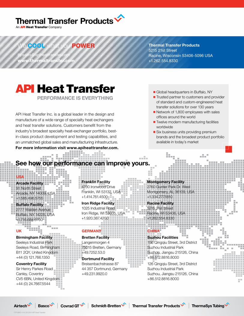
See how our performance can improve yours.
UK
Birmingham FacilitySeeleys Industrial ParkSeeleys Road, Birmingham B11 2QY, United Kingdom+44 (0) 121.766.1350
Coventry Facility Sir Henry Parkes Road Canley, Coventry CV5 6BN, United Kingdom+44 (0) 24.7667.5544
CHINA
Suzhou Facilities 156 Qingqiu Street, 3rd District Suzhou Industrial Park Suzhou, Jiangsu 215126, China +86.512.8816.8000
126 Qingqiu Street, 3rd District Suzhou Industrial Park Suzhou, Jiangsu 215126, China +86.512.8816.8000
GERMANy
Bretten FacilityLangenmorgen 475015 Bretten, Germany+49.7252.53.0
Dortmund FacilityBreisenbachstrasse 87 44 357 Dortmund, Germany+49.231.9920.0
USA
Arcade Facility91 North StreetArcade, NY 14009, USA+1.585.496.5755
Buffalo Facility 2777 Walden AvenueBuffalo, NY 14225, USA+1.716.684.6700
Franklin Facility 4700 Ironwood DriveFranklin, WI 53132, USA+1.414.761.4500
Iron Ridge Facility 1025 Industrial RoadIron Ridge, WI 53035, USA+1.920.387.4200
Montgomery Facility2760 Gunter Park Dr. WestMontgomery, AL 36109, USA+1.334.277.1810
Racine Facility5215 21st StreetRacine, WI 53406, USA+1.262.554.8330
TTP-BRO-1/14 | © 2014 API Heat Transfer
API Heat Transfer Inc. is a global leader in the design and manufacture of a wide range of specialty heat exchangers and heat transfer solutions. Customers benefit from the industry’s broadest specialty heat-exchanger portfolio, best- in-class product development and testing capabilities, and an unmatched global sales and manufacturing infrastructure. For more information visit www.apiheattransfer.com.
n Global headquarters in Buffalo, NYn Trusted partner to customers and provider
of standard and custom-engineered heat transfer solutions for over 130 years
n Network of 1,800 employees with sales offices around the world
n Twelve modern manufacturing facilities worldwide
n Six business units providing premium brands and the broadest product portfolio available in today’s market
Thermal Transfer Products5215 21st StreetRacine, Wisconsin 53406-5096 USA+1.262.554.8330
www.thermaltransfer.com
We COOL what you POWER