2013 residential appendices
TRANSCRIPT

RESIDENTIAL APPENDICES

2013 Residential Appendices RA1-2
Appendix RA1 - Special Case Residential Field Verification and Diagnostic Test Protocols
Residential Appendix RA1
Appendix RA1 - Special Case Residential Field Verification and Diagnostic Test Protocols Note: The HVAC Sizing procedures previously assigned to the 2008 version of RA1 have been moved to the 2013 ACM reference manual.
Table of Contents
Appendix RA1 – Special Case Residential Field Verification and Diagnostic Test Protocols .................... 2
RA1.1 Special Case Protocol Approval .......................................................................................................... 3
RA1.1.1 Special Case Refrigerant Charge Verification Protocol Approval .................................................... 3
RA1.2 Winter Setup for the Standard Charge Measurement Procedure ....................................................... 3
RA1.2.1 Purpose and Scope .......................................................................................................................... 3
RA1.2.2 Winter Setup for the Standard Charge Measurement Procedure .................................................... 4
RA1.2.3 Additional Requirements and Qualifications .................................................................................... 4

2013 Residential Appendices RA1-3
Appendix RA1 - Special Case Residential Field Verification and Diagnostic Test Protocols
RA1.1 Special Case Protocol Approval Field verification and diagnostic test protocols other than those described in Reference Residential Appendix RA3 are possible, and when field verification or diagnostic testing measurements can be reliably determined by methods, procedures or instrumentation other than those specified in Reference Residential Appendix RA3, such alternative protocols shall be allowed if approved by the Commission. The Commission may grant such approval after reviewing submittals from the applicant. Special Case Protocols that are approved by the Commission shall be published as an addendum to Reference Residential Appendix RA1.
RA1.1.1 Special Case Refrigerant Charge Verification Protocol Approval
The applicant for a special case refrigerant charge verification protocol shall provide information that specifies:
(a) the required instrumentation,
(b) the instrumentation accuracy,
(c) the parameters measured,
(d) the required calculations,
(e) the target values for system operating parameters for verification of optimum system operation,
(f) the allowable deviations from target values for system operating parameters,
(g) the requirements for reporting system faults.
Manufacturers that elect to utilize a special case protocol for compliance with refrigerant charge verification requirements in the Standards shall certify to the Energy Commission that use of the special case refrigerant charge verification protocol produces equipment performance at a sensible EER at AHRI Standard 210/240 standard rating conditions (80°F indoor dry-bulb, 67°F indoor wet-bulb, and 95°F outdoor dry-bulb) that deviates less than or equal to 5 percent from the sensible EER determined by laboratory testing at the AHRI Standard 210/240 standard rating conditions when the air conditioner is charged with the manufacturer's specified refrigerant charge determined by measurement of the weight of the specified refrigerant charge. The deviations from the manufacturer's target values of system operating parameters, that correspond to the maximum allowable 5 percent deviation in sensible EER shall be determined and reported to the Energy Commission by the manufacturer, and shall be utilized as the required compliance criteria for HERS Rater refrigerant charge verification. Deviations of system operating parameters from the manufacturer's target values for less than 5 percent deviation in sensible EER (tighter tolerances) may be specified by the manufacturer for use by the installing contractor.
Manufacturers using special case refrigerant charge verification protocols shall, upon request, provide comprehensive engineering specification documentation, installation and technical field service documentation, and user instructions documentation to installers and service personnel that utilize the procedure.
RA1.2 Winter Setup for the Standard Charge Verification Procedure
RA1.2.1 Purpose and Scope
The purpose of this procedure is to verify that residential split system air conditioners and heat pumps have the required refrigerant charge and that the metering device is working as designed. The procedures only apply to ducted split system central air-cooled air conditioners and ducted split system central air-source heat pumps for which the system manufacturer has specified that this procedure may be used to verify refrigerant charge.

2013 Residential Appendices RA1-4
Appendix RA1 - Special Case Residential Field Verification and Diagnostic Test Protocols
The Standard Charge Verification Procedure (Section RA3.2.2 of the Reference Residential Appendices) calls for the outdoor temperature to be within the manufacturer's specified range. When outdoor temperatures are below 70°F, the setup for the Standard Charge Verification Procedure must be modified in order to achieve the proper system pressure differential needed for the procedure. The Winter Setup for the Standard Charge Verification Procedure (Winter Charge Setup) allows both installers and HERS Raters to utilize the Standard Charge Verification Procedure of RA3.2.2 in the winter. Note that the Weigh-in Charging Procedure specified in Section RA3.2.3 may also be used only by the installer.
The Winter Charge Setup creates the right conditions at the unit being tested for outdoor temperatures above 37°F and below 71°F that allow the system to operate in the same range of pressure differences between the low side pressure and the high side pressure as occurs during warm outdoor temperatures.
The Winter Charge Setup is used only for units equipped with variable metering devices, which include Thermostatic Expansion Valves (TXV) and Electronic Expansion Valves (EXV) for which the manufacturer specifies subcooling as the means for determining the proper charge for the unit, including units equipped with micro-channel heat exchangers. The Winter Charge Setup achieves an appropriate high side - low side pressure differential to conduct the Standard Charge Verification Procedure, by restricting the airflow at the condenser fan outlet through the use of a Condenser Outlet Air Restrictor. Once this pressure differential is achieved, the Variable Metering Device Calculations are conducted in the same way as the variable metering device procedures described in Reference Residential Appendix RA 3.2.2.6.2. All other applicable requirements of Section RA3.2.2 remain the same and must also be completed when using the Winter Charge Setup,
Definition - Condenser Outlet Air Restrictor: A device which restricts the free area of the outlet from the condenser fan to reduce the air flow, but does not interfere with air entering the condenser coil. The amount of restriction shall be adjustable to allow the operator to vary the airflow to achieve the target refrigerant pressure difference.
RA1.2.2 Winter Setup for the Standard Charge Verification Procedure
(a) Install the condenser outlet air restrictor on the outlet from the condenser fan:
Position the restrictor so it does not interfere with the inlet airflow to the condenser. Start the air conditioner or heat pump in the cooling mode and restrict the outlet until the difference between the high side pressure and the low side pressure is between 160 psi and 220 psi for R-410A refrigerant and 100 to 145 psi for R-22 refrigerant. 160 psi ≤ (Phigh, – Plow ) ≤ 220 psi for R-410A refrigerant; 100 psi ≤ (Phigh, – Plow ) ≤ 145 psi for R-22 refrigerant
Allow the unit to stabilize for 15 minutes, watching the pressures to make sure the differential achieves and remains within 160 psi ≤ (Phigh, – Plow ) ≤ 220 psi for R-410A refrigerant
100 psi ≤ (Phigh, – Plow ) ≤ 145 psi for R-22 refrigerant
(b) Follow the test procedures specified in the Reference Residential Appendix, Section RA3.2.2.6.2, Variable Metering Device Calculations to determine compliance.
RA1.2.3 Additional Requirements and Qualifications
The Winter Charge Setup may only be used for equipment for which the air conditioning manufacturer approves the use of the Winter Charge Setup. Refer to the Energy Commissions website for the list of split system air conditioner units approved by the manufacturers to use the Winter Charge Setup. In addition to the requirements of Section RA1.2, manufacturers may issue additional instructions/clarification for the equipment and procedures required to be used to conduct the Winter Charge Setup. These additional instruction/clarifications shall also be available on the Energy Commission website: www.energy.ca.gov/title24/.

2013 Residential Appendices RA1-5
Appendix RA1 - Special Case Residential Field Verification and Diagnostic Test Protocols
Winter Charge Setup may be used for systems that use a target subcooling for refrigerant charge verification, including units equipped with micro-channel heat exchangers where the manufacturer specifies subcooling for measuring refrigerant charge.
Similar to the Standard Charge Verification Procedure for warm weather, the Winter Charge Setup may be used by the Installer and/or the HERS Rater.
The system shall comply with the minimum system airflow requirements specified in Reference Residential Appendix Section RA3.2.2.7.
Similar to the Standard Charge Verification Procedure for warm weather, the Winter Charge Setup requires that the return air dry bulb temperature must be maintained within the manufacturer's specification during the test, as specified in RA3.2.2. Suggestions for methods to accomplish warmer return air are posted on the Energy Commission website at the following link:
www.energy.ca.gov/title24/2008standards/changeout/documents/Refrigerant_Charge_Verification_Protocol.pdf
Similar to the Standard Charge Measurement Procedure for warm weather, the Winter Charge Setup procedure does not relieve the installing contractor from any obligations to follow manufacturers’ specifications. The procedures in Section RA1.2 are used to demonstrate compliance with Title 24, Part 6 requirements for refrigerant charge verification.

2013 Residential Appendices RA2-1
Appendix RA2 – Residential HERS Verification, Testing, and Documentation Procedures
Residential Appendix RA2
Appendix RA2 – Residential HERS Verification, Testing, and Documentation Procedures
Table of Contents
Appendix RA2 – Residential HERS Verification, Testing, and Documentation Procedures ....................... 1
RA2.1 California Home Energy Rating Systems ............................................................................................ 2
RA2.2 Measures that Require Field Verification and Diagnostic Testing ...................................................... 2
RA2.3 Documentation and Communication Requirements for HERS Verification Compliance .................... 4
RA2.3.1 Documentation Constraints, Registration, and Validation ............................................................... 5
RA2.3.2 Summary of Documentation and Communication Procedures ........................................................ 6
RA2.4 Summary of Responsibilities ............................................................................................................... 7
RA2.4.1 Builder .............................................................................................................................................. 7
RA2.4.2 HERS Provider and Rater ................................................................................................................ 7
RA2.4.3 Third Party Quality Control Program ................................................................................................ 8
RA2.4.4 Enforcement Agency ........................................................................................................................ 9
RA2.5 Installer Requirements - Certificate of Installation Documentation ..................................................... 9
RA2.5.1 Field Verification, Diagnostic Testing, and Certificate of Installation Registration ......................... 10
RA2.6 HERS Procedures – Verification, Testing, and Sampling ................................................................. 10
RA2.6.1 HERS Procedures - General Requirements .................................................................................. 10
RA2.6.2 HERS Procedures - Initial Model Field Verification and Diagnostic Testing .................................. 11
RA2.6.3 HERS Procedures – Group Sample Field Verification and Diagnostic Testing ............................. 11
RA2.6.4 HERS Procedures - Re-sampling, Full Testing and Corrective Action .......................................... 14
RA2.7 Third Party Quality Control Programs ............................................................................................... 16
RA2.8 Installer Requirements and HERS Procedures for Alterations ......................................................... 17

2013 Residential Appendices RA2-2
Appendix RA2 – Residential HERS Verification, Testing, and Documentation Procedures
RA2.1 California Home Energy Rating Systems Compliance for certain energy efficiency measures, as specified by the Commission, requires field verification and diagnostic testing of dwelling units by a certified Home Energy Rating System (HERS) Rater. The Commission approves HERS Providers, subject to the Commission’s HERS regulations, which appear in the California Code of Regulations, Title 20, Division 2, Chapter 4, Article 8, Sections 1670-1675. Approved HERS Providers are authorized to certify HERS Raters and are required to maintain quality control over HERS Rater field verification and diagnostic testing activities.
When the Certificate of Compliance documentation for a dwelling unit indicates that field verification and diagnostic testing of specific energy efficiency measures are required as a condition for complying with Title 24, Part 6, an approved HERS Provider and certified HERS Rater shall be used to conduct the field verification and diagnostic testing according to the applicable procedures in Appendix RA2. HERS Raters shall be considered special inspectors by enforcement agencies and shall demonstrate competence, to the satisfaction of the building official, for the visual inspections and diagnostic testing that they perform. Per California Code of Regulations, Title 20, Division 2, Chapter 4, Article 8, Section 1673(j)(2), “Providers and Raters shall be independent entities from the builder and from the subcontractor installer of energy efficiency improvements field verified or diagnostically tested.” An “Independent Entity means having no financial interest in, and not advocating or recommending the use of any product or service as a means of gaining increased business with, firms or persons specified in California Code of Regulations Title 20, Division 2, Chapter 4, Article 8, Sections 1671 and 1673(j).” Third Party Quality Control Programs approved by the Commission may serve some of the functions of HERS Raters for field verification purposes as specified in Section RA2.7.
The remainder of this Appendix RA2 describes the:
(a) Measures that require field verification or diagnostic testing;
(b) Requirements for documentation and communication for HERS verification compliance processes;
(c) Responsibilities assigned to each of the parties involved in the field verification and diagnostic testing process;
(d) Requirements for procedures for installing contractors and Certificate of Installation documentation;
(e) Requirements for HERS Rater field verification and diagnostic testing and documentation procedures;
(f) Requirements for sampling procedures for HERS verification compliance;
(g) Requirements for Third Party Quality Control Programs;
(h) Requirements for HERS verification compliance for alterations to existing dwellings.
RA2.2 Measures that Require Field Verification and Diagnostic Testing Table RA2-1 describes the measures that require installer certification and HERS Rater field verification and diagnostic testing, and identifies the protocol or test procedure in the Reference Residential Appendices that shall be used for completing installer and HERS Rater field verification and diagnostic testing.

2013 Residential Appendices RA2-3
Appendix RA2 – Residential HERS Verification, Testing, and Documentation Procedures
Table RA2-1 – Summary of Measures Requiring Field Verification and Diagnostic Testing Measure Title Description Procedure(s)
Duct Measures
Duct Sealing Component Packages require that space conditioning ducts be sealed. If sealed and tested ducts are claimed for compliance, field verification and diagnostic testing is required to verify that approved duct system materials are utilized, and that duct leakage meets the specified criteria.
RA3.1.4.3
Supply Duct Location, Surface Area and R-value
Compliance credit can be taken for improved supply duct location, surface area and R-value. Field verification is required to verify that the duct system was installed according to the design, including location, size and length of ducts, duct insulation R-value and installation of buried ducts.1 For buried ducts measures, Duct Sealing and High Quality Insulation Installation (QII) is required.
RA3.1.4.1
Verification of ducts located entirely in directly conditioned space, and Low Leakage Ducts in Conditioned Space
When the Standards specify use of the procedures in Section RA3.1.4.3.8 to determine if space conditioning system ducts are located entirely in directly conditioned space, the duct system location shall be verified by diagnostic testing. Compliance credit can be taken for verified duct systems with low air leakage to the outside when measured in accordance with Reference Residential Appendix Section RA3.1.4.3.8. Field Verification for ducts in conditioned space is required. Duct sealing is required.
RA3.1.4.3.8
Low Leakage Air-handling Units
Compliance credit can be taken for installation of a factory sealed air handling unit tested by the manufacturer and certified to the Commission to have met the requirements for a Low Leakage Air-Handling Unit. Field verification of the air handler’s model number is required. Duct Sealing is required.
RA3.1.4.3.9
Verification of Return Duct Design
Verification to confirm that the return duct design conform to the criteria given in TABLE 150.0-C or TABLEable 150.0-D.
RA3.1.4.4
Verification of Air Filter Device Design
Verification to confirm that the air filter devices conform to the requirements given in Standards Section 150.0(m)12.
RA3.1.4.5
Verification of Bypass Duct Prohibition
Verification to determine if system is zonally controlled, and confirm that bypass ducts are not used as required by Section 150.1(c)13.
RA3.1.4.6
Air Conditioning Measures
Improved Refrigerant Charge
Component Packages require in some climate zones that air-cooled air conditioners and air-source heat pumps be diagnostically tested in the field to verify that the system has the correct refrigerant charge. For the performance method, the Proposed Design is modeled with less efficiency if diagnostic testing and field verification is not performed. The system must also meet the prerequisite minimum System Airflow requirement.
RA3.2 RA1.2
Installation of Charge Indicator Display
Component Packages specify that a Charge Indicator Display can be installed as an alternative to refrigerant charge testing. The existence of a Charge Indicator Display has the same calculated benefit as refrigerant charge testing. Field verification is required.
RA3.4.2
Verified System Airflow When compliance requires verified system airflow greater than or equal to a specified criterion, field verification and diagnostic testing is required.
RA3.3
Air-handling Unit Fan Efficacy
When compliance requires verified fan efficacy (Watt/cfm) less than or equal to a specified criterion, field verification and diagnostic testing is required.
RA3.3
Verified Energy Efficiency Ratio (EER)
Compliance credit can be taken for increased EER by installation of specific air conditioner or heat pump models. Field verification is required.2
RA3.4.3 RA3.4.4.1
Verified Seasonal Energy Efficiency Ratio (SEER)
HERS Rater field verification of the SEER rating is required for some systems. RA3.4.3 RA3.4.4.1
Maximum Rated Total Cooling Capacity
The calculations for determining Maximum Rated Total Cooling Capacity need not be field verified, but the prerequisites to taking the credit –Minimum Cooling Coil Airflow, duct sealing, and Verified EER/SEER – must be field verified and diagnostically tested.
RA3.1.4.3, RA3.3, RA3.4.3 RA3.4.4.1
Evaporatively Cooled Condensers
Compliance credit can be taken for installation of evaporatively cooled condensers. Field verification of duct leakage is required. Field verification of refrigerant charge is required. Field verification of EER is required.
RA3.1.4.3, RA3.2 RA3.4.3. RA3.4.4.1

2013 Residential Appendices RA2-4
Appendix RA2 – Residential HERS Verification, Testing, and Documentation Procedures
Measure Title Description Procedure(s)
Ice Storage Air Conditioners
Compliance Credit can be taken for installation of distributed energy storage equipment. Field verification of duct sealing is required. Field verification of refrigerant charge is required.
RA3.1.4.3, RA3.2, RA3.4.3. RA3.4.4.1
Mechanical Ventilation Measures
Continuous Whole-Building Mechanical Ventilation Airflow
Measurement of whole-building mechanical ventilation is mandatory for newly constructed buildings.
RA3.7.4.1
Intermittent Whole-Building Mechanical Ventilation Airflow
Measurement of whole-building mechanical ventilation is mandatory for newly constructed buildings.
RA3.7.4.2
Building Envelope Measures
Building Envelope Air Leakage
Compliance credit can be taken for reduced building envelope air leakage. Field verification and diagnostic testing is required.
RA3.8
High Quality Insulation Installation (QII)
Compliance Software recognizes standard and improved envelope construction. Compliance credit can be taken for quality installation of insulation. Field verification is required.
RA3.5
Quality Insulation Installation for Spray Polyurethane Foam (SPF) Insulation
A HERS Rater shall verify the installation of SPF insulation whenever R-values other than the default R-value per inch are used for compliance.
RA3.5.6
Single Family Domestic Hot Water Measures
Verified Pipe Insulation Credit (PIC-H) Inspection to verify that all hot water piping in non-recirculating systems is insulated and
that corners and tees are fully insulated. No piping should be visible due to insulation voids with the exception of the last segment of piping that penetrate walls and delivers hot water to the sink, appliance, etc.
RA3.6.3.
Verified Parallel Piping (PP-H)
Inspection that requires that the measured length of piping between the water heater and single central manifold does not exceed five feet
RA3.6.4
Verified Compact Hot Water Distribution System (CHWDS-H)
Field verification to insure that the longest pipe run from any use point to the water heater serving that use point does not exceed a maximum length as Specified in RA 3.6.5.
RA3.6.5
Verified Point of USE (POU-H)
Inspection that all hot water fixtures in the dwelling unit, with the exception of the clothes washer, must be located within a restricted length (total piping length) based on pipe diameter from a water heater. To meet this requirement, most houses will require multiple water heaters
RA3.6.6
Demand Recirculation: Manual Control (RDRmc-H)
Inspection to verify that all recirculating hot water piping is insulated and that corners and tees are fully insulated. No piping should be visible due to insulation voids
RA3.6.7
Demand Recirculation: Sensor Control(RDRsc-H)
Inspection to verify that all recirculating hot water piping is insulated and that corners and tees are fully insulated. No piping should be visible due to insulation voids.
RA3.6.8
Multi Family Domestic Hot Water Heating Measures
Multiple Recirculation Loop Design for DHW Systems Serving Multiple Dwelling Units
Inspection that a central DHW system serving a building with more than eight dwelling units has at least two recirculation loops, each serving roughly the same number of dwelling units. These recirculation loops may the same water heating equipment or be connected to independent water heating equipment.
RA3.6.9
1. Note: Compliance credit for increased duct insulation R-value (not buried ducts) may be taken without field verification if the R-value is the same throughout the building, and for supply ducts located in crawlspaces and garages where all supply registers are either in the floor or within 2 feet of the floor. These two credits may be taken subject only to enforcement agency inspection. 2. Note: The requirement for verification of a high EER does not apply to equipment rated only with an EER.
RA2.3 Documentation and Communication Requirements for HERS Verification Compliance

2013 Residential Appendices RA2-5
Appendix RA2 – Residential HERS Verification, Testing, and Documentation Procedures
The building energy compliance features, HERS field verification requirements, and applicable special feature eligibility criteria shall be identified on a Certificate of Compliance that conforms to the requirements in Standards Sections 10-103(a)1 and 10-103(a)2. The builder or subcontractor shall submit all applicable Certificate of Installation documentation in conformance with the requirements in Standards Section 10-103(a)3 and the procedures described in RA2, and shall provide certification that the construction/installation complies with all applicable requirements on the Certificate of Compliance and complies with all applicable field verification and eligibility criteria. Field verification shall be performed by a HERS Rater and documented on applicable Certificate of Verification documentation that conforms to the requirements of Standards Section 10-103(a)5 and the procedures in RA2.
RA2.3.1 Documentation Constraints, Registration, and Verification
The performance compliance method allows for preparation of Certificate of Compliance documentation for multifamily buildings that precludes use of certain HERS verification compliance credits that would otherwise be available for compliance credit as described in Section RA2.3.1.1 below. Document registration is required for all dwelling units that utilize building energy features for which HERS verification is required as introduced in Section RA2.3.1.2 and described in the procedures in subsequent sections of RA2. Verification of electronic documentation is introduced in section RA2.3.1.3 and is applicable to many aspects of the documentation procedures described in subsequent sections of RA2.
RA2.3.1.1 Whole-Building Compliance Approach for Multifamily Buildings
For multi-family buildings, a single Certificate of Compliance may be prepared for the whole building, however dwelling unit-specific Certificates of Installation and dwelling unit-specific Certificates of Verification shall be required for each individual dwelling unit in the building. Thus, for the whole-building compliance approach in a multifamily building utilizing features that require HERS verification, the required energy compliance documentation for each dwelling unit shall consist of a copy of the whole-building Certificate of Compliance, the applicable dwelling unit-specific Certificates of Installation, and the applicable dwelling unit-specific Certificates of Verification.
When the whole-building compliance approach is utilized for a multifamily building, some energy efficiency measures that require HERS field verification shall not be used for compliance credit in performance compliance calculations. These measures require dwelling unit-specific information input to the compliance software, and dwelling unit-specific information that must be shown on the Certificate of Compliance, thus these measures cannot be properly documented using a whole-building Certificate of Compliance (which is not a dwelling unit-specific document type). The HERS measures that shall not be utilized for the multifamily whole-building compliance approach are:
(a) Buried Ducts credit
(b) Deeply Buried Ducts credit
(c) Reduced Supply Duct Surface Area credit
(d) Maximum Rated Total Cooling Capacity credit
(e) Building Envelope Sealing credit (blower door test)
All other measures that require HERS field verification and diagnostic testing are allowed for use with the multifamily whole-building compliance approach.
RA2.3.1.2 Document Registration
For all low-rise residential buildings for which compliance requires HERS field verification, all compliance documentation (Certificate of Compliance, Certificate of Installation, and Certificate of Verification) required for the dwelling unit shall be submitted for registration and retention to a HERS Provider data registry. When submittal of documentation to a HERS Provider data registry is required, the completed documents are referred to as registered documents, and the process of completing these documents by submitting information and certification signatures to the HERS Provider data registry is called registration. Refer to Reference Joint

2013 Residential Appendices RA2-6
Appendix RA2 – Residential HERS Verification, Testing, and Documentation Procedures
Appendix JA1 for the definitions for HERS Provider data registry, and for registered document. Additional specification for the document registration process is given in Reference Joint Appendix JA7.
RA2.3.1.3 Verification of Registered Documents
Printed paper copies or electronic copies of the completed, signed, registered Certificate of Compliance, Certificate of Installation, and Certificate of Verification documentation shall be allowed for use for required submittals to enforcement agencies, subject to verification that the information shown on the submitted document(s) conforms to the information shown on the current revision of the registered document(s) on file in the HERS Provider data registry for the applicable dwelling unit.
The HERS Provider shall make document verification services available via phone, internet, or utilization of digital technologies, to enable enforcement agency officials, builders, installation contractors, HERS Raters, and other authorized users of the HERS Provider data registry to verify that the information shown on submitted documentation is consistent with the information shown on the current revision of the registered document on file in the HERS Provider data registry for the applicable dwelling unit.
RA2.3.2 Summary of Documentation and Communication Procedures
The documentation and communication process for measures that require field verification and diagnostic testing is summarized below. The subsequent sections of this chapter contain additional information and requirements that apply to all situations; however the section on alterations, RA2.8, applies specifically to the differences in the requirements for alterations. Section RA2.7 applies specifically to the differences in the requirements for Third Party Quality Control Programs.
(a) A Certificate of Compliance shall be prepared for each dwelling unit or building that requires a building permit. The Certificate of Compliance information shall be submitted to the HERS Provider data registry, validated, and signed by the documentation author and the building’s designer or owner to register the documentation prior to submittal of the Certificate of Compliance to the enforcement agency for approval. The documentation author and the building designer or owner shall submit certification to the HERS Provider data registry electronically.
(b) The builder shall arrange for the services of a certified HERS Rater prior to installation of the measures, so that once the installation is complete the HERS Rater has ample time to complete the field verification and diagnostic testing without delaying final approval of the dwelling unit by the enforcement agency. The Builder shall make available to the HERS Rater a copy of the Certificate of Compliance that was approved/signed by the building designer or owner and submitted to the enforcement agency.
(c) The builder or subcontractor shall install the measure(s) that require field verification and diagnostic testing. When the installation is complete, the builder or subcontractor shall perform diagnostic testing on the installation using the applicable procedures specified in Reference Residential Appendix RA2.5, RA3, and RA1. If testing confirms compliance, the builder or subcontractor shall submit the required information and signatures electronically to the HERS Provider data registry to register the applicable Certificate(s) of Installation, then post a copy of the applicable registered Certificate(s) of Installation at the building site for review by the enforcement agency in conjunction with requests for final inspection for each dwelling unit.
(d) The HERS Rater shall confirm that registration of the Certificate(s) of Compliance and the applicable Certificate(s) of Installation has been completed for each dwelling unit that requires HERS verification. The HERS Rater shall complete the applicable field verification and diagnostic testing as specified in Section RA2.6. The HERS Rater shall submit the required field verification and diagnostic testing information and signatures electronically to the HERS Provider data registry to register the applicable Certificate of Verification documentation.
(e) The HERS Provider shall make available registered copies of the Certificate(s) of Verification to the HERS Rater, builder, enforcement agency and other authorized users of the HERS Provider data registry.

2013 Residential Appendices RA2-7
Appendix RA2 – Residential HERS Verification, Testing, and Documentation Procedures
(f) The enforcement agency shall not approve a dwelling unit until the enforcement agency has received the required registered Certificate(s) of Verification, posted at the building site for review in conjunction with requests for final inspection for the dwelling. The HERS Provider shall make document verification services available, to enforcement agencies, builders and contractors, HERS Raters, the Energy Commission, and other authorized users of the HERS Provider data registry. The HERS Provider shall ensure that the content and approval signatures for copies of submitted Certificate(s) of Compliance, Certificate(s) of Installation, and Certificate(s) Verification are retained per Title 20, Division 2, Chapter 4, Article 8, Section 1673(e).
RA2.4 Summary of Responsibilities Section RA2.4 summarizes responsibilities set forth in Appendix RA2 and organizes them by the responsible party. This section is not, however, a complete accounting of the responsibilities of the respective parties.
RA2.4.1 Builder
The builder shall make arrangements for submittal of the Certificate of Compliance information and certification signatures to the HERS Provider data registry for dwelling units with features that require HERS verification. The builder shall make arrangements for the services of a certified HERS Rater prior to installation of the features, so that once the installation is complete the HERS Rater has ample time to complete the field verification and diagnostic testing without delaying final approval of the building permit by the enforcement agency. The Builder shall make available to the HERS Rater a copy of the Certificate of Compliance that was approved/signed by the building designer or owner and submitted to the enforcement agency.
The builder or subcontractor responsible for the installation shall complete and sign all applicable Certificates of Installation to certify that the installation work meets the requirements for compliance credit shown on the Certificate of Compliance and that all applicable field verification and diagnostic test results reported on Certificates of Installation are accurate. The builder or subcontractor shall post a copy of all applicable Certificates of Installation at the construction site for review by the enforcement agency in conjunction with requests for final inspection for each dwelling unit. The builder or subcontractor shall also make available to the HERS Rater copies of all applicable Certificates of Installation.
If the builder utilizes group sampling for HERS verification compliance, the builder, builder’s authorized representative, or the HERS Rater shall identify the dwelling units to be included in the sample group for field verification and diagnostic testing. The HERS Rater, with no direction from the installer or builder, shall randomly select one dwelling unit from a sample group for field verification and diagnostic testing upon receiving the builder’s or builder representative’s request for HERS verification of that group.
The builder shall arrange for copies of all applicable registered Certificates of Verification to be posted at the building site for review by the enforcement agency in conjunction with requests for final inspection for each dwelling unit.
When re-sampling reveals a failure (see Section RA2.6.4), the builder is required to offer at no charge to all building owners for occupied dwelling units in the group to complete field verification, diagnostic testing and corrective action if necessary. Building owners may decline to have field verification and diagnostic testing and corrective action completed for the dwelling unit. The builder shall report the identifying location of any dwelling unit in which the building owner declines field verification and diagnostic testing and corrective action to the HERS Provider. The builder shall take corrective action as required in all unoccupied dwelling units in the group and in occupied dwelling units in the group where building owners have accepted field verification, diagnostic testing and corrective action.
The builder shall leave in the building, for the building owner at occupancy, copies of all compliance, operating, maintenance, and ventilation information specified in applicable sections of Title 24, Part 1, Section 10-103(b).
RA2.4.2 HERS Provider and Rater
The HERS Provider shall maintain a data registry with the capability to receive and store electronic data and image information provided by authorized users of the data registry sufficient to facilitate administration of all

2013 Residential Appendices RA2-8
Appendix RA2 – Residential HERS Verification, Testing, and Documentation Procedures
applicable document registration procedures and HERS compliance verification procedures as described in Reference Residential Appendix RA2 and Reference Joint Appendix JA7. Data registry capabilities include a secure web-based interface accessible by authorized users, and the ability to receive and process data transfer files generated by the Title 24 performance compliance software tools or other approved data input software. For sampling purposes, the HERS Provider shall maintain a list of the dwelling units in a group, the features that require Field Verification and Diagnostic Testing, the dwelling units selected for sample testing for each feature and the dwelling units that were not tested, the results of the sample testing, the dwelling units that were tested and verified as a result of re-sampling, and any corrective action taken.
For all dwelling units that require HERS verification for compliance, the HERS Provider shall retain records of all information and approval signatures for completed Certificates of Compliance, Certificates of Installation, and Certificates of Verification for a period of ten years per Title 20, Division 2, Chapter 4, Article 8, Section 1673(e).
The HERS Rater who provides field verification and diagnostic testing shall transmit the required test results and certification signatures to the HERS Provider data registry. Registered Certificates of Verification from the Provider shall be made available for the tested dwelling unit and each of the remaining untested dwelling units from a designated group for which compliance is verified based on the results of a sample test. The registered Certificates of Verification shall be made available to the HERS Rater, the builder, the enforcement agency, and to other authorized users of the HERS Provider data registry.
The HERS Rater shall produce a separate Certificate of Verification for each dwelling unit that meets the requirements for compliance. The registered Certificate of Verification shall have unique HERS Provider-designated identifiers for registration number and sample group number, and shall include lot location or address, building permit number, time and date stamp, Provider logo, water mark or official seal, and indicate if the dwelling unit has been tested or if it was an untested dwelling unit approved as part of sample group. The HERS Rater shall not submit a Certificate of Verification for a dwelling unit that does not have a completed Certificate of Installation submitted by the installer as required in Section RA2.5.
If field verification and diagnostic testing on a sampled dwelling unit identifies a failure to meet the requirements for compliance credit, the HERS Rater shall report to the HERS Provider, the builder, and the enforcement agency that re-sampling will be required.
If re-sampling identifies another failure, the HERS Rater shall report to the HERS Provider, the builder, and the enforcement agency that field verification and diagnostic testing will be required for all the untested dwelling units in the group. The report shall specify the identifying location of all dwelling units that shall be fully tested.
(a) The HERS Provider shall also report to the builder once diagnostic testing and field verification has shown that the failures have been corrected in all of the dwelling units except those for which the building owner has declined field verification, diagnostic testing, and corrective action. When field verification and diagnostic testing confirm that the requirements for compliance have been met, the HERS Provider shall make available the applicable registered Certificate(s) of Verification for each dwelling unit in the group.
The HERS Provider shall file a report with the enforcement agency if there has been a failure on a re-sample within a group, explaining all actions taken (including field verification, testing, corrective actions, offers to building owners for testing and corrective action, and building owner declines of such offers) to bring into compliance dwelling units for which full testing has been required.
RA2.4.3 Third Party Quality Control Program
An approved Third Party Quality Control Program shall:
(a) Provide training to participating program installing contractors, installing technicians, and specialty Third Party Quality Control Program subcontractors regarding compliance requirements for measures for which diagnostic testing and field verification is required,
(b) Collect data from participating installers for each installation completed for compliance credit,
(c) Complete data checking analysis to evaluate the validity and accuracy of the data to independently determine whether compliance has been achieved,

2013 Residential Appendices RA2-9
Appendix RA2 – Residential HERS Verification, Testing, and Documentation Procedures
(d) Provide direction to the installer to retest and correct problems when data checking determines that compliance has not been achieved,
(e) Require resubmission of data when retesting and correction is directed, and
(f) Maintain a database of all data submitted by participating program installing contractors, installing technicians, and specialty Third Party Quality Control Program subcontractors, and shall provide functionality that allows Energy Commission staff to query retained data or documents.
The HERS Provider shall arrange for the services of an independent HERS Rater to conduct independent field verifications of the installation work performed by the participating installing contractor and Third Party Quality Control Program, completing all of the responsibilities of a HERS Rater as specified in Appendix RA2 with the exception that sampling shall be completed for a group of up to thirty dwelling units.
RA2.4.4 Enforcement Agency
The enforcement agency at its discretion may require independent testing and field verification to be scheduled so that it can be completed in conjunction with the enforcement agency’s required inspections, or observe the field verification and diagnostic testing performed by builders, subcontractors or the certified HERS Rater in conjunction with the enforcement agency’s required inspections to corroborate the results documented on the Certificate(s) of Installation and on the Certificate(s) of Verification.
For dwelling units that have used a compliance alternative that requires field verification and diagnostic testing, the enforcement agency shall not approve a dwelling unit until the enforcement agency has received, in accordance with Title 24, Part 1 Section 10-103(a), Section 10-103(d) and the procedures in Appendix RA2, a registered copy of the Certificate of Compliance that has been completed and signed by the person responsible for the design; all applicable registered Certificates of Installation that have been completed and signed by the builder or subcontractor, and all applicable registered Certificates of Verification that have been completed and signed by the HERS Rater in conjunction with requests for final inspection for each dwelling unit. The HERS Provider shall make document verification services available to enforcement agencies, builders and contractors, HERS Raters, the Energy Commission, and other authorized users of the Provider data registry.
If necessary to avoid delay of approval of dwelling units completed when outside temperatures are below 55°F, the enforcement agency may approve compliance with the refrigerant charge verification requirements when installers have used the Weigh-in Charging Method described in Reference Residential Appendix RA3, Section RA3.2.3.1 and have not used the Section RA3.2.3.2 option for HERS verification compliance. This approval will be on the condition that installers submit to the enforcement agency a registered Certificate of Installation that includes a signed declaration indicating agreement to return to correct refrigerant charge if a HERS Rater determines at a later time when the outside temperature is 55°F or above, that correction is necessary. The HERS Provider shall track these projects to ensure a HERS Rater conducts the required refrigerant charge verification for all such systems. When the outdoor temperature is 55°F or above, the HERS Rater shall use the RA3.2.2 standard charge verification procedure, or a procedure approved by the HVAC system manufacturer and Energy Commission for the refrigerant charge verification. The HERS Rater shall report the diagnostic results on the applicable Certificate of Verification, and shall register the certificate with the HERS Provider. When refrigerant charge verification testing performed by the HERS Rater indicates adjustment to the charge is required, the HERS Provider shall notify the installer, and the builder or building owner that corrective action is required. The HERS Provider may also notify the enforcement agency that corrective action is required. All air-cooled air conditioners and air-source heat pumps that utilize the Weigh-In Method shall be verified by a HERS Rater using one of the applicable refrigerant charge verification procedures. Compliance with HERS verification requirements cannot utilize group sampling procedures when the installer utilized the Weigh-In Method.
RA2.5 Installer Requirements - Certificate of Installation Documentation Certificates of Installation are required when dwelling units utilize features, materials, components, or manufactured devices that are required for compliance with the Appliance Efficiency Regulations and Title 24, Part 6. Certificates of Installation shall indicate the installed features, materials, components, or manufactured devices are in conformance with the specifications listed on the Certificate of Compliance for the dwelling. The builder or the installing subcontractor eligible under Division 3 of the Business and Professions Code to accept

2013 Residential Appendices RA2-10
Appendix RA2 – Residential HERS Verification, Testing, and Documentation Procedures
responsibility for construction or installation, in the applicable classification for the scope of work, shall sign and submit Certificate of Installation documentation and post a copy of the Certificate(s) at the building site for review by the enforcement agency in conjunction with requests for final inspection for each dwelling unit.
When the dwelling unit does not require HERS field verification for compliance, the Certificates of Installation that are posted in the field for review by the enforcement agency at final inspection are not required to be registered certificates from a HERS Provider data registry, but shall conform to all other applicable requirements of 10-103(a)3. The remainder of Section RA2.5 describes the documentation procedures for Certificates of Installation for dwelling units that require HERS verification.
RA2.5.1 Field Verification, Diagnostic Testing, and Certificate of Installation Registration
For the features, materials, components, or manufactured devices that are listed on the Certificate of Compliance indicating HERS verification is required for compliance, the builder shall arrange for the services of a certified HERS Rater prior to installation of the measures so that once the installation is complete the HERS Rater will have ample time to complete the required field verification and diagnostic testing without delaying final approval of the dwelling unit by the enforcement agency.
For all low-rise residential buildings for which compliance requires HERS field verification and diagnostic testing, the Certificate(s) of Installation shall be signed and submitted to a HERS Provider data registry as specified in Standards Section 10-103(a)3 to certify conformance with Part 6. When Standards Section 10-103(a)3 requires document registration, all Certificates of Installation that are applicable to the dwelling unit shall be registered.
When the installation of a measure is complete, the builder or the builder’s subcontractor shall perform all required field verification and diagnostic testing of the installation(s) to confirm compliance with the Standards utilizing the applicable procedures specified in Reference Residential Appendix RA3 or RA1, and submit, or make arrangements for submittal of all required Certificate of Installation information to a HERS Provider data registry. Submittal of Certificate of Installation information to the HERS Provider data registry shall be done electronically.
HERS Raters or other authorized users of the HERS Provider data registry may provide documentation author support to facilitate the submittal of the Certificate of Installation information to the HERS Provider data registry on behalf of the builder or the builder’s subcontractor when such facilitation has been authorized by the builder or subcontractor. Documentation authors shall provide an electronic signature to certify the documentation is accurate and complete. The builder or subcontractor who is eligible under Division 3 of the Business and Professions Code to take responsibility for the construction or installation, or their authorized representative, shall provide an electronic signature to register the Certificate of Installation, to certify the information provided on the Certificate is true and correct, and confirm that the construction or installation complies with the requirements shown on the dwelling unit's Certificate of Compliance that was approved by the enforcement agency. The builder or subcontractor shall make available a copy of the registered Certificate of Installation to the HERS Rater, and post a copy of the registered Certificate of Installation at the building site for review by the enforcement agency in conjunction with requests for final inspection for each dwelling unit.
RA2.6 HERS Procedures – Verification, Testing, and Sampling At the builder’s option, HERS field verification and diagnostic testing (HERS verification) shall be completed either for each and every dwelling unit, or alternatively for a dwelling unit sample from a designated group of dwelling units in which the same measure(s) requiring HERS verification is installed in each dwelling unit in the group. If the builder elects to demonstrate compliance utilizing group sampling, all applicable procedures described in Sections RA2.6.2, RA2.6.3, and RA2.6.4 shall be followed.
RA2.6.1 HERS Procedures - General Requirements
The general requirements in RA2.6.1 are applicable to all dwelling units that require HERS verification for compliance, and shall be incorporated into procedures specified in Sections RA2.6.2, RA2.6.3, and RA2.6.4 whenever applicable.

2013 Residential Appendices RA2-11
Appendix RA2 – Residential HERS Verification, Testing, and Documentation Procedures
The builder or the builder's authorized representative shall make available to the HERS Rater the names and license numbers of the subcontractors responsible for the installations in the dwelling units that require HERS verification; and a copy of the registered Certificate of Compliance that was signed and submitted by the person responsible for the building design and was approved by the enforcement agency.
The builder, builder's authorized representative, or subcontractor shall make available to the HERS Rater a copy of the applicable registered Certificate(s) of Installation signed and submitted by the builder or subcontractors responsible for the construction or installation as described in Section RA2.5.
Prior to performing field verification and diagnostic testing, the HERS Rater shall verify that registration of all applicable Certificate of Compliance documentation, and registration of all applicable Certificate of Installation documentation has been completed for all dwelling units for which compliance requires HERS verification. The HERS Rater shall confirm the installer’s diagnostic test results and all other Certificate of Installation information indicates compliance consistent with the requirements given in the plans and specifications and registered Certificate of Compliance documents approved by the enforcement agency for the dwelling.
The HERS Rater shall perform all applicable field verification and diagnostic testing.
If the HERS Rater's field verification and diagnostic testing determines that the requirements for compliance are met, the HERS Rater shall submit, or make arrangements for submittal of the Certificate of Verification testing information to the HERS Provider data registry.
Authorized users of the HERS Provider data registry that are not certified HERS Raters may provide documentation author support to facilitate submittal of the Certificate of Verification information to the HERS Provider data registry on behalf of the HERS Rater when such facilitation has been authorized by the HERS Rater. Documentation authors shall provide an electronic signature to certify the documentation is accurate and complete.
The Certificate of Verification shall be signed by the HERS Rater who performed the field verification and diagnostic testing services to certify that the information provided on the Certificate is true and correct.
A completed signed registered copy of the Certificate of Verification shall be posted at the building site for review by the enforcement agency in conjunction with requests for final inspection for each dwelling unit.
The HERS Provider shall make document verification services available, to enforcement agencies, builders and contractors, HERS Raters, the Energy Commission, and other authorized users of the HERS Provider data registry.
RA2.6.2 HERS Procedures - Initial Model Field Verification and Diagnostic Testing
The HERS Rater shall diagnostically test and field verify the first dwelling unit of each model within a subdivision or multifamily housing development when the builder elects to demonstrate HERS verification compliance utilizing group sampling. To be considered the same model, dwelling units shall have the same basic floor plan layout, energy design, and compliance features as shown on the Certificate of Compliance. Variations in the basic floor plan layout, energy design, compliance features, zone floor area, or zone volume, that do not change the HERS features to be tested, the heating or cooling capacity of the HVAC unit(s), or the number of HVAC units specified for the dwelling units, shall not cause dwelling units to be considered a different model. For multi-family buildings, variations in exterior surface areas caused by location of dwelling units within the building shall not cause dwelling units to be considered a different model. This initial model testing allows the builder to identify and correct any potential construction flaws or practices in advance of the build out of each model. If field verification and diagnostic testing determines that the requirements for compliance are met, the HERS Rater shall transmit the test results to the HERS Provider data registry, whereupon the Provider shall make available a registered copy of the Certificate of Verification, to the HERS Rater, the builder, the enforcement agency, and other authorized users of the HERS Provider data registry.
RA2.6.3 HERS Procedures – Group Sample Field Verification and Diagnostic Testing
Descriptions for HERS verification compliance using group sampling, and details describing procedures for sampling of a “closed” group of up to seven dwellings, and for sampling of an “open” group of up to five dwellings are described in Section RA2.6.3.

2013 Residential Appendices RA2-12
Appendix RA2 – Residential HERS Verification, Testing, and Documentation Procedures
RA2.6.3.1 Designation of Groups
After the initial model field verification and diagnostic testing is completed as specified in RA2.6.2, the builder, or the builder’s authorized representative shall determine a sampling procedure to be used, and shall designate the dwelling units to include in the group of dwellings that require HERS verification. The maximum number of dwelling units allowed in a sample group may range from five, to seven, to thirty as described in Sections RA2.6.3.3, RA2.6.3.4, and RA2.7 respectively.
If multiple measures requiring HERS verification are installed, each dwelling unit in a designated group shall have the same measures requiring HERS verification as the other dwelling units in the designated group. If some dwelling units have installed a different set of measures requiring HERS verification, those dwelling units shall be in a separate group.
If the dwelling units in a designated group have multiple measures that require HERS verification, sample testing for individual measures may be conducted in any of the dwelling units in the group - it is not required that all of the sample tests for all of the individual measures be completed in the same dwelling unit. Individual measures shall be allowed to be included in a group regardless of whether compliance requires one sample test, or if compliance requires more than one sample test (up to100% sample test rate) be reported for such individual measures.
Dwelling units in a designated group shall all be located within the same enforcement agency jurisdiction and subdivision or multifamily housing development. Refer also to Section RA2.8 for requirements for sample groups applicable to alterations.
If dwelling units have central forced-air space conditioning equipment that introduces outside air into the conditioned space utilizing means that connect outside air ventilation ducts directly to the dwelling unit’s central forced air duct system (Central Fan-Integrated Ventilation System or CFI Ventilation System), the CFI ventilation technology shall be considered a separate measure for HERS verification sampling purposes, and dwellings with CFI ventilation systems shall be placed in separate groups from other dwelling units that do not utilize CFI ventilation technology.
RA2.6.3.2 Group Status - "Open" Groups and "Closed" Groups
Submittal of the Certificate of Installation information, for at least one dwelling, to the HERS Provider data registry, is required in order to “open” a new group. Additional dwellings may be entered into the registry, and included in an “open” group over a period of time subject to submittal of the Certificate of Installation information to the registry for each additional dwelling. However the group shall not remain “open” to receive additional dwellings for a period longer than six months from the earliest date shown on any Certificate of Installation for a dwelling included in a group. A group may be “closed” at any time after the group has been “opened” at the option of the builder or builder’s authorized representative, thus the size of a “closed” group may range from a minimum of one dwelling to a maximum of seven dwellings. When a group becomes classified as “closed”, no additional dwellings shall be added to the group.
RA2.6.3.3 Sampling of a “Closed” Group of Up to Seven Dwellings
The following criteria shall be met as prerequisite to attaining HERS verification compliance for the group:
(a) All of the dwelling units contained in the sample group have been identified. A maximum of seven dwellings are allowed to be included in a “closed” sample group for HERS compliance.
(b) Installation of all the measures that require HERS verification has been completed in all the dwellings that are entered in the group, and registration of the Certificates of Installation for all the dwellings entered in the group has been completed.
(c) The group has been classified as a “closed” group in the Provider data registry
(d) At the request of the builder or the builder’s authorized representative, a HERS Rater shall randomly select one dwelling unit from the “closed” sample group for field verification and diagnostic testing. If the dwelling unit meets the compliance requirements, this “tested” dwelling and also each of the other “not-tested” dwellings in the group shall receive a registered Certificate of Verification.

2013 Residential Appendices RA2-13
Appendix RA2 – Residential HERS Verification, Testing, and Documentation Procedures
RA2.6.3.4 Sampling of an “Open” Group of Up to Five Dwellings
The following criteria shall be met as prerequisite to attaining HERS verification compliance for the group:
(a) At least one dwelling unit from the sample group has been identified. A maximum of five dwellings are allowed to be included in an “open” sample group for HERS compliance.
(b) Installation of all the measures that require HERS verification shall be completed in all the dwellings that are entered in the group, and registration of the Certificates of Installation for all the dwellings entered in the group has been completed.
(c) At the request of the builder, or the builder’s authorized representative, a HERS Rater shall randomly select one dwelling unit from those currently entered into the “open” sample group for field verification and diagnostic testing. If the dwelling unit meets the compliance requirements, the “tested” dwelling and also each of the other “not tested” dwellings currently entered into the group shall receive a registered Certificate of Verification. If less than five dwelling units have been entered into the group, the group shall be allowed to remain “open” and eligible to receive additional dwelling units. Dwelling units entered into the “open” group subsequent to the compliant HERS verification of the “tested” dwelling shall also receive a registered Certificate of Verification as a “not tested” dwelling subject to receipt of the registered Certificate of Installation by the HERS Provider data registry for the dwelling. The group shall be “closed” when it reaches the limit of five dwellings or when the six month limit for “open” groups has been exceeded, or when the builder requests that the group be closed.
RA2.6.3.5 Additional Requirements Applicable to Group Sampling Procedures
The builder or the HERS Rater may request removal of untested dwelling units from a group by notifying the HERS Provider prior to selection of the dwelling sample that will be tested from an “open” or “closed” group and shall provide justification for the change. Removed dwelling units shall be field verified and diagnostically tested individually or shall be included in a subsequent group for sampling.
There are exceptions to the requirement to have completed Certificate of Installation data entered into the HERS Provider data registry prior to selection of the dwelling unit to be tested in a group. Some HERS measures require multiple verifications during the construction process. A sample group is not required to be closed before HERS field verification and diagnostic testing can begin for the following measures. For these measures the HERS Rater is allowed to randomly select the dwelling unit to be field verified from those that are at the proper stage of construction to enable the first of the multiple verifications to be completed.
(a) Quality Installation of Insulation measure requires inspection of the air barrier and inspection of the insulation behind tubs and showers at framing rough-in. Verification of the wall, floor and ceiling insulation must be completed prior to drywall installation. Attic insulation installation may require follow-up verification.
(b) Buried Ducts measure requires verification of the duct design prior to verification of the attic insulation.
(c) Duct Surface Area requires verification of the duct design prior to installation of the attic insulation.
The HERS Rater, with no direction from the installer or builder, shall randomly select one dwelling unit from a “closed” sample group for field verification and diagnostic testing upon receiving the builder’s or builder representative’s request for HERS verification of that group. Alternatively, the HERS Rater shall randomly select one dwelling unit from the dwellings currently entered into an “open” sample group upon receiving the builder’s or builder representative’s request for HERS verification of that group. The HERS Rater shall diagnostically test and field verify the selected dwelling unit. The HERS Rater shall enter the test and/or field verification results into the HERS Provider data registry regardless of whether the results indicate a pass or fail. If the test fails, then the failure must be entered into the Provider’s data registry even if the installer immediately corrects the problem. In addition, the procedures in Section RA2.6.4 shall be followed.
If field verification and diagnostic testing determines that the requirements for compliance are met, the HERS Rater shall enter the test results into the HERS Provider data registry. Whereupon the Provider shall make available to the HERS Rater, the builder, the enforcement agency, and other approved users of the HERS Provider data registry, a registered copy of the Certificate of Verification for the “tested” dwelling, and for all other “not tested” dwelling units entered in the group at the time of the sample test. The registered Certificate of

2013 Residential Appendices RA2-14
Appendix RA2 – Residential HERS Verification, Testing, and Documentation Procedures
Verification shall report the successful diagnostic testing results and conclusions regarding compliance for the tested dwelling unit. The registered Certificate of Verification shall also provide:
(a) Building permit number for the dwelling unit.
(b) Registration Number that conforms to the numbering convention specified in Reference Joint Appendix JA7.
(c) Group Number that conforms to the numbering convention specified in Reference Joint Appendix JA7.
(d) Time and date stamp of the Provider’s issuance of the registered Certificate of Verification.
(e) Provider’s logo, water mark, or official seal.
(f) Indication that the dwelling was a “tested” dwelling, or was a “not-tested” dwelling in a sample group.
Whenever the builder changes subcontractors who are responsible for a feature that is being diagnostically field verified and tested, the builder shall notify the HERS Rater of the subcontractor change, and terminate sampling for any affected groups. All dwelling units utilizing features that require HERS verification for compliance that were installed by previous subcontractors or were subject to verification and testing under the supervision of a previous HERS Provider, for which the builder does not have a completed Certificate of Verification, shall be individually tested or included in a separate group for sampling. Dwelling units with installations completed by new subcontractors shall be individually tested or shall be included in a new sampling group.
The HERS Rater shall not notify the builder when sample testing will occur prior to the completion of the work that is to be tested, or prior to registration of the Certificate of Installation.
The HERS Provider shall “close” any “open” group within 6 months after the earliest signature date shown on any Certificate of Installation for a dwelling entered in the group. When such group closure occurs, the HERS Provider shall notify the builder that the group has been “closed,“ and require that a sample dwelling shall be selected for field verification and diagnostic testing by a HERS Rater if field verification has not yet been conducted on a sample dwelling entered in the group.
RA2.6.4 HERS Procedures - Re-sampling, Full Testing and Corrective Action
“Re-sampling” refers to the procedure that requires testing of additional dwellings within a group when the initial selected sample dwelling from a group fails to comply with the HERS verification requirements.
When a failure is encountered during sample testing, the failure shall be entered into the HERS Provider data registry. Corrective action shall be taken on the failed dwelling unit and the dwelling unit shall be retested to verify that corrective action was successful. Corrective action and retesting on the dwelling unit shall be repeated until the testing indicates compliance and the successful compliance results have been entered into the HERS Provider data registry (or the dwelling unit complies using an alternative method). Whereupon, a registered Certificate of Verification for the dwelling shall be made available to the HERS Rater, the builder, the enforcement agency, and other authorized users of the HERS Provider data registry.
In addition, the HERS Rater shall conduct re-sampling to assess whether the first failure in the group is unique, or if the rest of the dwelling units in the group are likely to have similar failings.
RA2.6.4.1 Re-sampling procedures for a “closed” group of up to seven dwellings:
The HERS Rater shall randomly select for re-sampling one of the remaining untested dwelling units in the group for retesting of the feature that failed. If the failed dwelling was entered in a “closed” group, and the testing of the second randomly selected dwelling unit in the group confirms that the requirements for compliance credit are met on that unit, then the dwelling unit with the initial failure shall not be considered an indication of failure in the remaining untested dwelling units in the group. The HERS Rater shall transmit the re-sample test results to the HERS Provider registry, whereupon the Provider shall make available to the HERS Rater, the builder, the enforcement agency, and other authorized users of the HERS Provider data registry, a registered copy of the Certificate of Verification for the remaining dwelling units in the group including the dwelling unit in the re-sample.

2013 Residential Appendices RA2-15
Appendix RA2 – Residential HERS Verification, Testing, and Documentation Procedures
If field verification and diagnostic testing of the second sample results in a failure, the HERS Rater shall report the second failure to the HERS Provider, the builder, and the enforcement agency. All dwelling units in the group must thereafter be individually field verified and diagnostically tested to confirm compliance for the feature that failed to comply with re-sampling. In cases where corrective action would require destruction of building components, the builder may choose to reanalyze compliance and choose different measures that will achieve compliance. In this case a new Certificate of Compliance shall be completed and submitted to the HERS Provider, the HERS Rater, and the enforcement agency. Even with a new Certificate of Compliance, the dwelling unit must be individually field verified and diagnostically tested. Upon verification of compliance, the HERS Rater shall enter the test results into the HERS Provider data registry. Whereupon the Provider shall make available to the HERS Rater, the builder, the enforcement agency, and other authorized users of the HERS Provider data registry, a registered copy of the Certificate of Verification for each individual dwelling in the group.
RA2.6.4.2 Re-sampling procedures for an “open” group of up to five dwellings:
The HERS Rater shall randomly select for re-sampling one of the remaining untested dwelling units in the group for retesting of the feature that failed. If the failed dwelling was entered in an “open” group, and there are no other untested dwellings entered in the “open” group at the time of the failed HERS verification, subsequent dwellings entered into the “open” group shall not receive a Certificate of Verification until a second dwelling in the “open” group is tested and successfully complies. If the subsequent testing of the second dwelling unit in the group confirms that the requirements for compliance credit are met on that unit, then the dwelling unit with the initial failure shall not be considered an indication of failure in the untested dwelling units in the group. The HERS Rater shall transmit the compliant re-sample test results to the HERS Provider data registry, whereupon the Provider shall make available to the HERS Rater, the builder, the enforcement agency, and other authorized users of the HERS Provider data registry, a registered copy of the Certificate of Verification, for the re-sampled dwelling, and the remaining not yet tested dwelling units entered in the “open” group at the time of the re-sample test, and the group shall be allowed to remain open and eligible to receive additional dwelling units. Dwelling units entered into the “open” group of up to 5 dwellings following the successful HERS verification of the re-sampled dwelling shall receive a Certificate of Verification as a “not tested” dwelling subject to registration of the Certificate of Installation by the HERS Provider data registry for the dwelling.
If field verification and diagnostic testing of the second sample results in a failure, the HERS Rater shall report the second failure to the HERS Provider, the builder, and the enforcement agency, and the Provider shall require the “open” group to be “closed”. All remaining untested dwelling units entered in the group at the time of the re-sample must thereafter be individually field verified and diagnostically tested. In cases where corrective action would require destruction of building components, the builder may choose to reanalyze compliance and choose different measures that will achieve compliance. In this case, a new Certificate of Compliance shall be completed and submitted to the HERS Provider, the HERS Rater, and the enforcement agency. Even with a new Certificate of Compliance, the dwelling unit must be individually field verified and diagnostically tested. Upon verification of compliance, the HERS Rater shall enter the test results into the HERS Provider data registry. Whereupon the Provider shall make available to the HERS Rater, the builder, the enforcement agency, and other authorized users of the HERS Provider data registry, a registered copy of the Certificate of Verification for each individual dwelling in the group.
RA2.6.4.3 Corrective Action
Builders shall offer to provide the necessary field verification and diagnostic testing services and any necessary corrective action at no charge to building owners (for a definition of “building owner” and of other terms used, see Reference Joint Appendix JA1) in occupied dwelling units in the group. Builders shall report to the HERS Provider the identifying location of any dwelling unit in which the building owner or occupant declines field verification and diagnostic testing and corrective action. The HERS Provider shall verify that the builder has made this offer. If a building owner of a dwelling unit declines this offer, field verification, diagnostic testing, and corrective action will not be required for that dwelling unit and the dwelling unit will no longer be considered a part of the group. If a building owner accepts this offer, the builder shall take corrective action, and the HERS Rater shall conduct field verification and diagnostic testing to verify that problems have been corrected. Upon verification of compliance, the HERS Rater shall transmit the test results to the HERS Provider data registry.

2013 Residential Appendices RA2-16
Appendix RA2 – Residential HERS Verification, Testing, and Documentation Procedures
Whereupon the Provider shall make available to the HERS Rater, the builder, the enforcement agency, and other authorized users of the HERS Provider data registry, a registered copy of the Certificate of Verification for the dwelling unit.
The HERS Provider shall file a report with the enforcement agency explaining all actions taken (including field verification, diagnostic testing, corrective action, offers to building owners for testing and corrective action, and/or building owner declines of such offers) to bring into compliance dwelling units for which full testing has been required. If corrective action requires work not specifically exempted by the CMC or the CBC, the builder shall obtain a permit from the enforcement agency prior to commencement of any of the work.
Corrections to avoid reporting a failure to the HERS Provider data registry shall not be made to a sampled dwelling unit after the HERS Rater selects the sample dwelling unit. If it is evident that such corrections have been made to a sampled dwelling unit to avoid reporting a failure, field verification and diagnostic testing shall be required for 100 percent of the dwelling units in the group.
RA2.7 Third Party Quality Control Programs The Commission may approve Third Party Quality Control Programs that serve some of the functions of HERS Raters for field verification purposes but do not have the authority to sign compliance documentation as a HERS Rater. Third Party Quality Control Programs shall provide training to installers regarding compliance requirements for measures for which diagnostic testing and field verification is required. Third Party Quality Control Programs shall collect data from participating installers for each installation completed for compliance credit, provide data checking analysis to evaluate the validity and accuracy of the data to independently determine whether compliance has been achieved, provide direction to the installer to retest and correct problems when data checking determines that compliance has not been achieved, require resubmission of data when retesting and correction is directed, and maintain a database of all data submitted by installers and shall provide functionality that allows Energy Commission staff to query retained data or documents. The data that is collected by the Third Party Quality Control Program shall be more detailed than the data required for showing compliance with the Standards, shall provide an independent check on the validity and accuracy of the installer’s claim that compliance has been achieved, and shall not be alterable by the installer to indicate that compliance has been achieved when in fact compliance has not been achieved.
The HERS Provider shall arrange for the services of a HERS Rater to conduct independent field verification of the installation work performed by the participating Third Party Quality Control Program installing contractor. The HERS Rater shall complete all of the responsibilities of a HERS Rater as specified in Appendix RA2, with the exception that sampling procedures utilized shall be limited to sampling of a “closed” group as described in Section RA2.6.3. However, the sample tested shall be selected and field verified from within a group of up to thirty dwelling units. The HERS Rater shall be an independent entity from the Third Party Quality Control Program. If re-sampling is required, full testing and corrective action shall be completed as specified in Section RA2.6.4 with the exception that re-sampling shall be completed for a minimum of one out of every thirty dwelling units from the group. The Third Party Quality Control Program shall not impose restrictions on the HERS Rater or the HERS Provider that limit their independence, or the ability of the HERS Rater or the HERS Provider to properly perform their functions. For example, the Third Party Quality Control Program shall not impose restrictions on the HERS Rater’s use of equipment beyond those required by the Commission.
The Third Party Quality Control Program shall meet the requirements imposed on a HERS Rater specified in the Commission’s HERS Program regulations (California Code of Regulations, Title 20, Division 2, Chapter 4, Article 8, Sections 1670 -1675), including the requirement to be an independent entity from the builder, the HERS Rater that provides independent field verifications, and the subcontractor installer as specified by Section 1673(j). However, a Third Party Quality Control Program may have business relationships with installers participating in the program to advocate or promote the program and an installer’s participation in the program, and to advocate or promote products that the Third Party Quality Control Program sells to installers as part of the Program.
Prior to approval by the Commission, the Third Party Quality Control Program shall provide a detailed explanation to the Commission of 1) the data that is to be collected from the installers, 2) the data checking process that will be used to evaluate the validity and accuracy of the data, 3) the justification for why this data checking process will provide strong assurance that the installation actually complies, and 4) the format for the

2013 Residential Appendices RA2-17
Appendix RA2 – Residential HERS Verification, Testing, and Documentation Procedures
database that will be maintained and the functionality that will allow Energy Commission staff to query retained data or documents. The Third Party Quality Control Program may apply for a confidential designation of this information as specified in the Commission’s Administrative Regulations (California Code of Regulations, Title 20, Division 2, Chapter 7, Article 2, Section 2505). The Third Party Quality Control Program shall also provide a detailed explanation of the training that will be provided to installers, and the procedures that it will follow to complete independent field verifications.
The Third Party Quality Control Program certified installing contractor and the installing contractor’s responsible installing technicians shall be required to be trained in quality installation procedures; the requirements of this Appendix RA2; and any other applicable specialized Third Party Quality Control Program-specific procedures as a condition to participation in the program. The training requirements also apply to the installing contractor’s specialty subcontractors who provide Third Party Quality Control Program services. All installation verification and diagnostic work performed in the program shall be subject to the same quality assurance procedures as required by the Energy Commission’s HERS program regulations.
The Third Party Quality Control Program shall be considered for approval as part of the rating system of a HERS Provider, which is certified as specified in the Commission’s HERS Program regulations, Section 1674. A Third Party Quality Control Program can be added to the rating system through the recertification of a certified HERS Provider as specified by Title 20, Division 2, Chapter 4, Article 8, Section 1674(e).
RA2.8 Installer Requirements and HERS Procedures for Alterations This section on alterations describes the differences that apply to alterations. Otherwise the procedures and requirements detailed in previous sections of Appendix RA2 shall also apply to alterations. For alterations, building owners or their agents may carry out the actions that are assigned to builders in previous sections of AppendixRA2.
Applicable procedures for registration of compliance documents described in Appendix RA2 shall also apply to alterations.
When compliance for an alteration requires field verification and diagnostic testing, the building owner may choose for the field verification and diagnostic testing to be completed for the dwelling unit individually, or alternatively, as part of a designated sample group of dwelling units for which the same installing company has completed work that requires HERS verification for compliance.
When sampling is utilized for HERS verification compliance for alterations, the dwelling units in a designated sample group are not required to be located within the same enforcement agency jurisdiction. However, to enable the enforcement agency to schedule testing to accomplish the corroboration of field verification and diagnostic testing procedures performed by the building owner, subcontractors, or certified HERS Rater as described in Section RA2.4.4, the enforcement agency may require that a separate dwelling unit from the sample group that is located within its jurisdiction be tested.
The building owner or agent of the building owner shall submit, or make arrangements for submittal of the required Certificate of Compliance information to the HERS Provider data registry to complete the applicable Certificate of Compliance documentation in accordance with the requirements in Standards Section 10-103(a)1 and 10-103(a)2.
When the enforcement agency does not require building design plans to be submitted with the application for a building permit for an alteration, the applicable registered Certificate of Compliance documentation specified in 10-103(a)1 is not required to be approved by the enforcement agency prior to issuance of a building permit, but shall be approved by the enforcement agency prior to final inspection of the dwelling unit, and shall be made available to the enforcement agency for all applicable inspections as specified in Standards Section 10-103(a)2A.
HERS Raters or other authorized users of the HERS Provider data registry may provide documentation author support to facilitate the submittal of the required Certificate of Compliance information to the HERS Provider data registry on behalf of the building owner or agent of the building owner, when such facilitation has been authorized by the building owner or agent of the building owner. Documentation authors shall provide an electronic signature to certify the documentation is accurate and complete. The building owner or agent of the

2013 Residential Appendices RA2-18
Appendix RA2 – Residential HERS Verification, Testing, and Documentation Procedures
building owner who is eligible under Division 3 of the Business and Professions Code to take responsibility for the design specification for the alteration shall provide an electronic signature to register the Certificate of Compliance, to certify the information provided on the Certificate is true and correct, to certify conformance with Part 6, and shall submit the registered Certificate of Compliance to the enforcement agency for approval.
The building owner or agent shall make available to the HERS Rater a copy of the registered Certificate of Compliance approved by the enforcement agency.
The installer shall perform diagnostic testing and the procedures specified in Section RA2.5.
When the installation is complete, the person responsible for the performance of the installation shall complete the Certificate of Installation in accordance with the procedures specified in Section RA2.5.
The HERS Rater shall perform the applicable verification and diagnostic testing required for compliance following the procedures in Section RA2.6. If group sampling is utilized for compliance, the sampling procedures described in Section RA2.6.3 for sampling of a ”closed” group of up to seven dwelling units shall be used, requiring that all dwelling units within the group have been serviced by the same installing company. The installing company may request a group for sampling that is smaller than seven dwelling units. Whenever a HERS Rater for the group is changed, a new group shall be established.
Re-sampling, full testing, and corrective action shall be completed, if necessary, as specified by Section RA2.6.4.
The enforcement agency shall not approve the alteration until the enforcement agency has received a completed Certificate of Installation as specified in Section RA2.5, and a completed Certificate of Verification as specified in Section RA2.6.
Third Party Quality Control Programs, as specified in Section RA2.7, may also be used with alterations, and shall be limited to “closed” sample group sizes of thirty dwelling units or less.
When a Third Party Quality Control Program is used, the enforcement agency may approve compliance based on the Certificate of Installation, where data checking has indicated that the unit complies, on the condition that if the required HERS verification procedures determine that re-sampling, full testing, or corrective action is necessary, such work shall be completed.

2013 Residential Appendices RA2-1
Appendix RA2 – Residential HERS Verification, Testing, and Documentation Procedures
(This page left intentionally blank)

2013 Residential Appendices RA3-1
Appendix RA3 – Residential Field Verification and Diagnostic Test Protocols
Residential Appendix RA3
Appendix RA3 – Residential Field Verification and Diagnostic Test Protocols
Table of Contents
Appendix RA3 – Residential Field Verification and Diagnostic Test Protocols ........................................... 1
RA3.1 Field Verification and Diagnostic Testing of Air Distribution Systems ................................................ 3
RA3.1.1 Purpose and Scope .......................................................................................................................... 3
RA3.1.2 Instrumentation Specifications ......................................................................................................... 3
RA3.1.3 Diagnostic Apparatus ....................................................................................................................... 4
RA3.1.4 Verification and Diagnostic Procedures ........................................................................................... 4
RA3.2 Field Verification and Diagnostic Testing of Refrigerant Charge for Air Conditioners and Heat Pumps 12
RA3.2.1 Purpose and Scope ........................................................................................................................ 12
RA3.2.2 Standard Charge Verification Procedure ....................................................................................... 14
RA3.2.3 Weigh-In Charging Procedure ........................................................................................................ 23
RA3.3 Field Verification and Diagnostic Testing of Forced Air System Airflow Rate, Fan Watt Draw, and Determination of Fan Efficacy. ......................................................................................................................... 28
RA3.3.1 Instrumentation Specifications ....................................................................................................... 28
RA3.3.2 Apparatus ....................................................................................................................................... 29
RA3.3.3 Procedures ..................................................................................................................................... 31
RA3.4 Field Verification of Installed HVAC System Components and Devices .......................................... 34
RA3.4.1 Purpose and Scope ........................................................................................................................ 34
RA3.4.2 Charge Indicator Display (CID) Verification Procedure .................................................................. 34
RA3.4.3 Time Delay Relay Verification Procedure ...................................................................................... 35
RA3.4.4 HVAC System Verification Procedures ......................................................................................... 35
RA3.5 Quality Insulation Installation Procedures ......................................................................................... 36
RA3.5.1 Purpose and Scope ........................................................................................................................ 36
RA3.5.2 Definitions ....................................................................................................................................... 36
RA3.5.3 BATT AND BLANKET INSULATION ............................................................................................. 40
RA3.5.4 LOOSE FILL INSULATION ............................................................................................................ 46
RA3.5.5 RIGID BOARD INSULATION ......................................................................................................... 52

2013 Residential Appendices RA3-2
Appendix RA3 – Residential Field Verification and Diagnostic Test Protocols
RA3.5.6 SPRAY POLYURETHANE FOAM INSULATION .......................................................................... 56
RA3.5.7 STRUCTURAL INSULATED PANEL (SIP) .................................................................................... 64
RA3.5.8 INSULATED CONCRETE FORM (ICF) ......................................................................................... 68
RA3.6 Field Verification of Water Heating Systems ..................................................................................... 73
RA3.6.1 Purpose and Scope ........................................................................................................................ 73
RA3.6.2 HERS-Verified Pipe Insulation Requirements for all Hot Water Distribution Systems .................. 73
RA3.6.3 HERS-Verified Pipe Insulation Credit (PIC-H) ............................................................................... 73
RA3.6.4 HERS-Verified Central Parallel Piping (PP-H) ............................................................................... 73
RA3.6.5 HERS-Verified Compact Hot Water Distribution System (CHWDS-H) .......................................... 74
RA3.6.6 HERS-Verified Point of Use (POU-H) ............................................................................................ 75
RA3.6.7 HERS Verified Demand Recirculation; Manual Control (R-DRmc-H) ............................................ 75
RA3.6.8 HERS-Verified Demand Recirculation: Sensor Control (RDRsc-H) ............................................. 76
RA3.6.9 HERS-Multiple Recirculation Loop Design for DHW Systems Serving Multiple Dwelling Units .... 77
RA3.7 Field Verification and Diagnostic Testing of Mechanical Ventilation Systems .................................. 78
RA3.7.1 Purpose and Scope ........................................................................................................................ 78
RA3.7.2 Instrumentation Specifications ....................................................................................................... 78
RA3.7.3 Diagnostic Apparatus for Measurement of Ventilation System Airflow .......................................... 78
RA3.7.4 Procedures ..................................................................................................................................... 79
RA3.8 Field Verification and Diagnostic Testing of Building Air Leakage .................................................... 81
RA3.8.1 Purpose and Scope ........................................................................................................................ 81
RA3.8.2 On-Site Inspection Protocol ........................................................................................................... 81
RA3.8.3 Protocol for Preparing the Building Enclosure for Testing ............................................................. 81
RA3.8.4 Accuracy Levels for Enclosure Leakage Testing ........................................................................... 83
RA3.8.5 Installation of the Blower Door Air Tightness Testing System and Preliminary Recordings .......... 84
RA3.8.6 Procedure for Conducting a Single-Point Air Tightness Test ........................................................ 84
RA3.8.7 Procedure for Conducting a Multi-Point Air Tightness Test ........................................................... 86
RA3.8.8 Procedure for Conducting a Repeated Single-Point Test .............................................................. 87
RA3.8.9 Application Results ......................................................................................................................... 89
RA3.8.10 Other Leakage Metrics: ................................................................................................................ 89
RA3.8.11 Equipment Accuracy and Requirements ...................................................................................... 90
RA3.8.12 Air Leakage Reporting ................................................................................................................. 90

2013 Residential Appendices RA3-3
Appendix RA3 – Residential Field Verification and Diagnostic Test Protocols
RA3.1 Field Verification and Diagnostic Testing of Air Distribution Systems
RA3.1.1 Purpose and Scope
RA3.1 contains procedures for measuring the air leakage in forced air distribution systems as well as procedures for verifying supply duct location, supply duct surface area, supply duct R-value, return duct design, return grille design, and air filter installation.
RA3.1 applies to air distribution systems in both new and existing low-rise residential buildings.
RA3.1 provides required procedures for installers, HERS raters and others who need to perform field verification of air distribution systems.
Table RA3.1-1 is a summary of the tests and criteria included in RA3.1.
Table RA3.1-2 Provides compliance criteria for the duct leakage test protocols in Section RA3.1.4.3.
Table RA3.1-1 – Summary of Duct System Field Verification and Diagnostic Test Protocols Verification/Diagnostic Description Procedure
Supply Duct Location, Surface Area and R-value
Verify duct system was installed according to the specifications on the Certificate of Compliance or in accordance with an approved duct system design layout.
RA3.1.4.1
Verified Duct System Design Procedure for duct system design layout approval and field verification RA3.1.4.1.1
Duct Leakage Verify that duct leakage is less than or equal to the compliance criteria given in Table RA3.1-2.
RA3.1.4.3
Return Duct Design Verify compliance with the return duct and return grill sizing requirements of Table 150.0-C or Table 150.0-D).
RA3.1.4.4
Air Filter Device Design Verify compliance with the requirements in 150(m)12. RA3.1.4.5
Verification of Prescriptive Bypass Duct Requirements
Verification to confirm zonally controlled systems comply with the bypass duct requirements in 150.1(c)13
RA3.1.4.6
RA3.1.2 Instrumentation Specifications
The instrumentation for the air distribution diagnostic measurements shall conform to the following specifications:
RA3.1.2.1 Pressure Measurements
All pressure measurements shall be measured with measurement systems (i.e. sensor plus data acquisition system) having an accuracy equal to or better than ± 1% of pressure reading or ± 0.2 Pa. (0.0008 inches water) (whichever is greater). All pressure measurements within the duct system shall be made with static pressure probes such as Dwyer A303 or equivalent.
RA3.1.2.2 Duct Leakage Measurements
Duct leakage airflow rates during duct leakage testing shall be measured with a duct leakage airflow rate measurement apparatus that has a duct leakage airflow rate measurement accuracy equal to or better than ± 3 percent of reading or ± 1 cfm (whichever is greater).
RA3.1.2.3 Calibration
All instrumentation used for duct leakage diagnostic measurements shall be calibrated according to the manufacturer’s calibration procedure to conform to the accuracy requirement specified in Section RA3.1.2.

2013 Residential Appendices RA3-4
Appendix RA3 – Residential Field Verification and Diagnostic Test Protocols
RA3.1.3 Diagnostic Apparatus
RA3.1.3.1 Apparatus for Duct Pressurization and Leakage Flow Measurement
The apparatus for fan pressurization duct leakage measurements shall consist of a duct pressurization and flow measurement device meeting the specifications in Section RA3.1.2.
RA3.1.3.2 Apparatus for Duct Leakage to Outside Measurement
The apparatus for measuring duct leakage to outside shall include a fan that is capable of maintaining the pressure within the conditioned spaces in the house at 25 Pa (0.1 inches water) relative to the outdoors. The fan most commonly used for this purpose is known as a “blower door” and is typically installed within a temporary seal of an open exterior doorway.
RA3.1.3.3 Apparatus for Smoke-Test of Accessible-Duct Sealing (Existing Duct Systems)
The apparatus for determining leakage in and verifying sealing of all accessible leaks in existing duct systems provide means for introducing controllable amounts of non-toxic visual/theatrical smoke into the duct pressurization apparatus for identifying leaks in accessible portions of the duct system. The means for generating smoke shall have sufficient capacity to ensure that any accessible leaks will emit visibly identifiable smoke.
RA3.1.4 Verification and Diagnostic Procedures
This section describes the procedures used to verify compliance with the mandatory and performance compliance requirements for air distribution systems.
RA3.1.4.1 Diagnostic Supply Duct Location, Surface Area and R-value
The performance compliance calculations allow credit for duct systems that are designed to be in advantageous locations, that have reduced supply duct surface areas, and/or that provide higher R-values for portions of the system. This section specifies procedures for verification of duct systems for conformance with the requirements for the performance compliance credits. When indicated on the Certificate of Compliance, the Installer shall certify compliance with the applicable procedures in RA3.1.4.1 on a Certificate of Installation, and a HERS rater shall verify compliance on a Certificate of Verification.
RA3.1.4.1.1 Verified Duct System Design
An installed duct system meets the Verified Duct System Design compliance criteria if it is field verified by a HERS rater to be in conformance with a duct design layout that meets all applicable duct design and documentation requirements given in Section RA3.1.4.1.1. The duct design layout shall be approved by the enforcement agency.
RA3.1.4.1.1.1 Verified Duct System Design - Duct Design Layout
The duct system design shall be documented on the Duct Design Layout, a scaled layout drawing that identifies the location of the space conditioning equipment, all supply and return registers/grilles, the size, R-value, and location of each duct segment. The Duct Design Layout shall incorporate all other supply duct details reported on the registered Certificate of Compliance.
RA3.1.4.1.1.2 Verified Duct System Design - Compliance Criteria
The duct system design shall be based on an industry standard design methodology such as ACCA Manual D or an equivalent, and shall take into account: the available external static pressure from the air handler, the equivalent length or pressure drop of external devices, and the pressure drop of the duct runs accounting for size, type and configuration of the ducts and fittings. The duct system shall be designed to meet the required system airflow rate with the manufacturer-specified available external static pressure for the specified system

2013 Residential Appendices RA3-5
Appendix RA3 – Residential Field Verification and Diagnostic Test Protocols
air handler at that airflow. The duct system design shall include calculations that indicate the duct system will operate at equal to or greater than 0.0292 cfm/Btu (350 cfm/12000 Btu) in cooling speed (350 cfm per nominal ton of condensing unit cooling capacity specified by the manufacturer) or, if heating only, equal to or greater than 16.8 cfm per 1000 Btu/hr furnace nominal output specified by the manufacturer.
RA3.1.4.1.1.3 Verified Duct System Design - Duct Design Layout Approval
The Duct Design Layout shall be included with the building design plans and the registered Certificate of Compliance submitted to the enforcement agency in conjunction with the application for the building permit. A copy of the Duct Design Layout approved by the enforcement agency shall be posted or made available with the building permit(s) issued for the building, and shall be made available to the enforcement agency, installing contractor, and HERS rater for use during the installation work and for all applicable inspections.
RA3.1.4.1.1.4 Verified Duct System Design - Field Verification of Installation
The location of all supply and return registers shall be verified by inspection of the interior of the dwelling unit. The location of the space conditioning equipment and the size, R-value, and location of each duct segment shall be verified by observation in the spaces where they are located. Deviations from the approved Duct Design Layout shall not be allowed without a revised a Duct Design Layout approved by the enforcement agency.
RA3.1.4.1.2 Verification of 12 Linear Feet or Less of Duct Located Outside Of Conditioned Space
A visual inspection shall confirm space conditioning systems with air handlers located outside the conditioned space have 12 linear feet or less of duct located outside the conditioned space including air handler and plenum. If the space conditioning system has more than 12 feet of duct outside of conditioned space, the system does not pass.
RA3.1.4.1.3 Verification of Ducts Located In Conditioned Space
A visual inspection shall confirm space conditioning systems are located entirely in conditioned space. If any part of the space conditioning duct system is outside of conditioned space, the system does not pass.
RA3.1.4.1.4 Verification of Supply Duct Surface Area Reduction
Compliance with Verified Duct System Design procedures specified in RA3.1.4.1.1 are prerequisite for compliance with the Supply Duct Surface Area Reduction compliance credit. A visual inspection shall confirm the installed duct system layout conforms to the Duct Design Layout.
RA3.1.4.1.5 Verification of Buried Ducts on The Ceiling R-Value
Compliance with Verified Duct System Design procedures specified in RA3.1.4.1.1 is prerequisite for compliance with the Buried Ducts on the Ceiling compliance credit. A visual inspection shall confirm the installed duct system layout conforms to the Duct Design Layout. This procedure shall be carried out prior to covering the ducts with insulation.
Ducts designed to be buried shall be insulated to R4.2 or greater. In addition, ducts designed to be in contact with the ceiling shall be not more than 3.5 inches from the ceiling drywall. A sign shall be hung near the attic access that displays a warning: “Caution: Buried Ducts. Markers indicate location of buried ducts.” All ducts that will be completely buried shall have vertical markers that are visible after insulation installation, placed at least every 8 feet of duct length and at the beginning and end of each duct run.
RA3.1.4.1.6 Verification of Deeply Buried Ducts R-Value
Compliance with Verified Duct System Design procedures specified in RA3.1.4.1.1 is prerequisite for compliance with the Deeply Buried Ducts compliance credit. A visual inspection shall confirm the installed duct system layout conforms to the Duct Design Layout. This procedure shall be carried out prior to covering the ducts with insulation.

2013 Residential Appendices RA3-6
Appendix RA3 – Residential Field Verification and Diagnostic Test Protocols
Ducts designed to be buried shall be insulated to R4.2 or greater. In addition, ducts designed to be in contact with the ceiling shall be not more than 3.5 inches from the ceiling drywall. A sign shall be hung near the attic access that displays a warning: “Caution: Buried Ducts. Markers indicate location of buried ducts.” All ducts that will be completely buried shall have vertical markers that are visible after insulation installation, placed at least every 8 feet of duct length and at the beginning and end of each duct run.
RA3.1.4.2 Determining Air Handler Airflow for Calculation of Duct Leakage Rate Compliance Targets
For use in establishing the target duct leakage rate compliance criteria, the system air handler airflow shall be calculated using RA3.1.4.2.1, RA3.1.4.2.2, or RA3.1.4.2.3.
RA3.1.4.2.1 Default Air Handler Airflow
Default air handler airflow may be used only for homes where the duct system is being tested before the air conditioning and heating system is installed and the equipment specification is not known. For heating only systems the default air handler airflow shall be 0.5 CFM per ft² of Conditioned Floor Area.
RA3.1.4.2.2 Nominal Air Handler Airflow
For heating only systems the nominal air handler airflow shall be 21.7 CFM per kBtu/hr of rated heating output capacity. For systems with cooling, the nominal air handler airflow shall be 400 CFM per nominal ton of condensing unit cooling capacity as specified by the manufacturer or the heating only value, whichever is greater.
RA3.1.4.2.3 Measured System Airflow
The system airflow shall be as measured according to a procedure in Section RA3.3.3. The system airflow can be used as the air handler airflow for the purpose of establishing duct leakage percentage.
RA3.1.4.3 Diagnostic Duct Leakage
Diagnostic duct leakage measurement is used by installers and raters to verify that total leakage meets the criteria for any sealed duct system specified in the compliance documents. Diagnostic Duct Leakage from Fan Pressurization of Ducts (Section RA3.1.4.3.1) is the only procedure that may be used by a HERS rater to verify duct sealing in a new home. Table RA3.1-2 shows the leakage compliance criteria and test procedures that may be used to demonstrate compliance.

2013 Residential Appendices RA3-7
Appendix RA3 – Residential Field Verification and Diagnostic Test Protocols
Table RA3.1-2 – Duct Leakage Verification and Diagnostic Test Protocols and Compliance Criteria Case User Application Leakage Compliance Criteria
(% of Air Handler Airflow) Procedure(s)
Sealed and tested new duct systems in single family homes and townhomes
Installer Testing at Final HERS Rater Testing
6% RA3.1.4.3.1
Sealed and tested new duct systems in single family homes and townhomes
Installer Testing at Rough-in, Air Handling Unit Installed
6% Installer Inspection at Final
RA3.1.4.3.2 RA3.1.4.3.2.1 RA3.1.4.3.3
Sealed and tested new duct systems in single family homes and townhomes
Installer Testing at Rough-in, Air Handling Unit Not Installed
4% Installer Inspection at Final
RA3.1.4.3.2 RA3.1.4.3.2.2 RA3.1.4.3.3
Sealed and tested new duct systems in multi-family homes regardless of duct system location.
Installer Testing at Final HERS Rater Testing
12%Total Duct Leakage RA3.1.4.3.1
Sealed and tested new duct systems in multi-family homes regardless of duct system location.
Installer Testing at Final HERS Rater Testing
6% Leakage to Outside RA3.1.4.3.4
Verified Low Leakage Air Handler with Sealed and Tested Duct System Compliance Credit
Installer Testing at Final HERS Rater Testing
compliance target values 6% or less as specified on the Certificate of
Compliance
RA3.1.4.3.1 and RA3.1.4.3.9
Verification of ducts located entirely in directly conditioned space, and Low leakage ducts in conditioned space compliance credit.
Installed Testing HERS Rater Testing
25 CFM Leakage to Outside RA3.1.4.3.8
Sealed and tested altered existing duct systems
Installer Testing HERS Rater Testing
15% Total Duct Leakage RA3.1.4.3.1
Sealed and tested altered existing duct systems
Installer Testing HERS Rater Testing
10% Leakage to Outside RA3.1.4.3.4
Sealed and tested altered existing duct systems
Installer Testing and Inspection HERS Rater Testing and Verification
Fails Leakage Tests but All Accessible Ducts are Sealed
Inspection and Smoke Test with 100% Verification
RA3.1.4.3.5 RA3.1.4.3.6 RA3.1.4.3.7
RA3.1.4.3.1 Diagnostic Duct Leakage from Fan Pressurization of Ducts
The objective of this procedure is for an installer to determine or a rater to verify the total leakage of a new or altered duct system. The total duct leakage shall be determined by pressurizing the entire duct system to a positive pressure of 25 Pa (0.1 inches water) with respect to outside. The following procedure shall be used for the fan pressurization tests:
(a) Verify that the air handler, supply and return plenums and all the connectors, transition pieces, duct boots and registers are installed. The entire duct system shall be included in the total leakage test.
(b) For newly installed or altered ducts, verify that cloth backed rubber adhesive duct tape has not been used and if a platform or other building cavity used to house the air distribution system has been newly installed or altered, it contains a duct or is ducted with duct board or sheet metal.
(c) Seal all the supply registers and return grilles except for one large centrally located return grille or the air handler cabinet access panel.
(d) Attach the fan flowmeter device to the duct system at the unsealed return grille or the air handler cabinet access panel.
(e) Install a static pressure probe at a supply register located close to the air handler, or at the supply plenum.
(f) Adjust the fan flowmeter to produce a positive 25 Pa (0.1 inches water) pressure at the supply register or the supply plenum with respect to the outside or with respect to the building space with the entry door open to the outside.

2013 Residential Appendices RA3-8
Appendix RA3 – Residential Field Verification and Diagnostic Test Protocols
(g) Record the flow through the flowmeter; this is the leakage flow at 25 Pa (0.1 inches water).
(h) Divide the leakage flow by the total air handler airflow determined by the procedure in Section RA3.1.4.2 and convert to a percentage. If the leakage flow percentage is equal to or less than the compliance criterion from Table RA3.1-2 the system passes.
RA3.1.4.3.2 Diagnostic Duct Leakage at Rough-in Construction Stage
Installers may determine duct leakage in new construction by using diagnostic measurements at the rough-in building construction stage prior to installation of the interior finishing. When using this measurement technique, the installer shall complete additional inspection (as described in section RA3.1.4.3.3) of duct integrity after the finishing wall has been installed. In addition, after the finishing wall is installed, spaces between the register boots and the wallboard shall be sealed. Cloth backed rubber adhesive duct tapes shall not be used to seal the space between the register boot and the wall board.
The duct leakage measurement at rough-in construction stage shall be performed using a fan pressurization device. The duct leakage shall be determined by pressurizing both the supply and return ducts to 25 Pa (0.1 inches water). The following procedure (either RA3.1.4.3.2.1 or RA3.1.4.3.2.2) shall be used:
RA3.1.4.3.2.1 Ducts with the Air Handling Unit Installed and Connected:
For total leakage:
(a) Verify that supply and return plenums and all the collars, connectors, transition pieces, duct boots, and return boxes have been installed. If a platform or other building cavity is used to house portions of the air distribution system, it shall contain a duct, be lined with duct board or sheet metal, and all duct connectors and transition parts shall be installed and sealed. The platform, ducts, and connectors shall be included in the total leakage test. All joints shall be inspected to ensure that no cloth backed rubber adhesive duct tape is used.
(b) Seal all the supply duct boots and return boxes except for one return duct box.
(c) Attach the fan flowmeter device at the unsealed return duct box.
(d) Insert a static pressure probe at one of the sealed supply duct boots located close to the supply plenum or at the supply plenum.
(e) Adjust the fan flowmeter to maintain a positive 25 Pa (0.1 inches water) pressure in the duct system with respect to the outside, or with respect to the building space with the entry door open to the outside.
(f) Record the flow through the flowmeter; this is the leakage flow at 25 Pa (0.1 inches water).
(g) Divide the leakage flow by the total air handler airflow determined by the procedure in Section RA3.1.4.2 and convert to a percentage. If the leakage flow percentage is less than or equal to the compliance criterion from Table RA3.1-2 the system passes.
RA3.1.4.3.2.2 Ducts with Air Handling Unit Not Yet Installed:
For total leakage:
(a) Verify that supply and return plenums and all the collars, connectors, transition pieces, duct boots, and return boxes have been installed. If a platform or other building cavity is used to house portions of the air distribution system, it shall contain a duct, be lined with duct board or sheet metal, and all duct connectors and transition parts shall be installed and sealed. The platform, ducts and connectors shall be included in the total leakage test. All joints shall be inspected to ensure that no cloth backed rubber adhesive duct tape is used.
(b) Supply and return leaks may be tested separately, or the supply and return plenums may be connected together using suitable temporary air-tight means to facilitate testing the total system. If the supply and return systems are to be tested separately, the opening to the supply or return plenums shall be sealed to prevent leakage unless used as the point of attachment for the fan flowmeter.

2013 Residential Appendices RA3-9
Appendix RA3 – Residential Field Verification and Diagnostic Test Protocols
(c) Seal all the supply duct boots and/or return duct boxes except for a location where the fan flowmeter device will be attached.
(d) Attach the fan flowmeter device at the unsealed location..
(e) Insert a static pressure probe at one of the sealed supply duct boots, or return duct boxes, located at a point in the system close to the fan flowmeter.
(f) Adjust the fan flowmeter to produce a positive 25 Pa (0.1 inches water) pressure at the supply plenum with respect to the outside or with respect to the building space with the entry door open to the outside.
(g) Record the airflow through the flowmeter; this is the leakage flow at 25 Pa (0.1 inches water).
(h) If the supply and return ducts are tested separately, repeat items 4 through 6 with the flow meter attached to the unsealed return box and the static pressure probe in the return duct boxes, located at a point in the system close to the fan flowmeter, then add the two leakage rates together to get a total leakage flow.
(i) Divide the leakage flow by the total air handler airflow determined by the procedure in Section RA3.1.4.2 and convert to a percentage. If the leakage flow percentage is less than or equal to the compliance criterion from Table RA3.1-2 the system passes.
RA3.1.4.3.3 Installer Visual Inspection at Final Construction Stage
After installing the interior finishing wall and verifying that one of the above rough-in tests was completed, the following procedure shall be used:
(a) Remove at least one supply and one return register, and verify that the spaces between the register boot and the interior finishing wall are properly sealed.
(b) If the house rough-in duct leakage test was conducted without an air handler installed, inspect the connection points between the air handler and the supply and return plenums to verify that the connection points are properly sealed.
(c) Inspect all joints to ensure that no cloth backed rubber adhesive duct tape is used.
RA3.1.4.3.4 Duct Leakage to Outside from Fan Pressurization of Ducts
The objective of this test is to determine the amount of duct leakage to outside the air barrier for the conditioned space. This measurement is utilized to verify that duct systems are located entirely within conditioned space. The procedure is also utilized to provide an alternate leakage measurement for situations when it is likely that a portion of the total duct leakage is inside the air barrier for the conditioned space. The duct leakage to outside shall be determined by pressurizing the ducts and the conditioned space of the house to 25 Pa (0.1 inches water) with respect to outside. The following procedure shall be used for the fan pressurization test of leakage to outside:
(a) Seal all the supply registers and return grilles except for one large centrally located return grille or the air handler cabinet access panel.
(b) Attach the fan flowmeter device to the duct system at the unsealed return grille or the air handler cabinet access panel.
(c) Install a static pressure probe at the supply plenum.
(d) Attach a blower door to an external doorway.
(e) If any ducts are located in an unconditioned basement, all doors or accesses between the conditioned space and the basement shall be closed, and at least one operable door or window (if it exists) between the basement and outside shall be open during the test.
(f) If the ducts are located in a conditioned basement, any door between the basement and the remaining conditioned space shall be open, and any basement doors or windows to outside must be closed during the test.

2013 Residential Appendices RA3-10
Appendix RA3 – Residential Field Verification and Diagnostic Test Protocols
(g) Adjust the blower door fan to provide positive 25 Pa (0.1 inches of water) pressure in the conditioned space with respect to outside.
(h) Adjust the fan/flowmeter to maintain a zero pressure difference (plus or minus 0.5Pa (.002 inches water)) between the ducts and the conditioned space, and adjust the blower door fan to maintain a positive 25 Pa (0.1 inches of water) pressure in the conditioned space with respect to outside. This step may require several iterations.
(i) Record the flow through the flowmeter; this is the duct leakage flow to outside at 25 Pa (0.1 inches water). If the leakage flow is less than or equal to the applicable compliance criteria in Table RA3.1-2, the system passes.
(j) If required for compliance, divide the leakage flow by the system air handler airflow determined by the procedure in Section RA3.1.4.2, and convert to a percentage. If the leakage flow percentage is less than or equal to the criterion from Table 3.1-2 the system passes.
RA3.1.4.3.5 Sealing of All Accessible Leaks
For altered existing duct systems that are unable to pass either the Fan Pressurization of Ducts test (RA3.1.4.3.1), or the Duct Leakage to Outside test (RA3.1.4.3.4)), the objective of this test is to verify that all accessible leaks are sealed. The following procedure shall be used:
(a) Complete the leakage test specified in Section RA3.1.4.3.1 to measure the leakage before commencing duct sealing.
(b) Seal all accessible ducts.
(c) After sealing is complete, again use the procedure in RA3.1.4.3.1 to measure the leakage after duct sealing.
(d) Complete the Smoke Test as specified in RA3.1.4.3.6.
(e) Complete the Visual Inspection as specified in RA3.1.4.3.7.
RA3.1.4.3.6 Smoke-Test of Accessible-Duct Sealing
For altered existing ducts that fail the leakage tests, the objective of the smoke test is to confirm that all accessible leaks have been sealed. The following procedure shall be used:
(a) Inject either theatrical or other non-toxic smoke into a fan pressurization device that is maintaining a duct pressure difference of 25 Pa (0.1 inches water) relative to the duct surroundings, with all grilles and registers in the duct system sealed.
(b) Visually inspect all accessible portions of the duct system during smoke injection.
(c) The system shall pass the test if one of the following conditions is met:
1. No visible smoke exits the accessible portions of the duct system. 2. Smoke only emanates from the furnace cabinet which is gasketed and sealed by the manufacturer
and no visible smoke exits from the accessible portions of the duct system.
RA3.1.4.3.7 Visual Inspection of Accessible Duct Sealing
For altered existing ducts that fail the leakage tests, the objective of this inspection in conjunction with the smoke test (RA3.1.4.3.6) is to confirm that all accessible leaks have been sealed. Visually inspect to verify that the following locations have been sealed:
(a) Connections to plenums and other connections to the forced air unit
(b) Refrigerant line and other penetrations into the forced air unit
(c) Air handler door panel (do not use permanent sealing material, metal tape is acceptable)
(d) Register boots sealed to surrounding material

2013 Residential Appendices RA3-11
Appendix RA3 – Residential Field Verification and Diagnostic Test Protocols
(e) Connections between lengths of duct, as well as connections to takeoffs, wyes, tees, and splitter boxes.
RA3.1.4.3.8 Verification of Low Leakage Ducts in Conditioned Space Compliance Credit, and Ducts Located Entirely In Directly Conditioned Space
When ducts are located in conditioned space, additional performance compliance credit is available for low leakage ducts. If duct leakage to outside is equal to or less than 25 cfm when measured in accordance with Section RA3.1.4.3.4, the system passes. The dwelling must also be qualified to receive the credit for verified ducts in conditioned space as verified by visual inspection according to Section RA3.1.4.1.3.
When the Standards specify use of the procedures in Section RA3.1.4.3.8 to determine if space conditioning system ducts are located entirely in directly conditioned space, the duct system location shall be verified by diagnostic testing according to the following criterion: If duct leakage to outside is equal to or less than 25 cfm when measured in accordance with Section RA3.1.4.3.4, the system ducts shall be considered to be located entirely in directly conditioned space. Duct systems that do not meet this criterion shall not be considered to be located entirely in directly conditioned space.
RA3.1.4.3.9 Verification of Low Leakage Air-Handling Unit with Sealed and Tested Duct System
An additional performance compliance credit is available for verified low leakage ducts if a qualified low leakage air-handling unit is installed. The low leakage air-handling unit cabinet (furnace, or heat pump fan and inside coil) shall conform to the qualification requirements given in Reference Joint Appendix JA9, and shall be included in the list of low leakage air handling units published by the Energy Commission. The qualified air handler must be connected to a sealed and tested new duct system to receive the credit.
In order to comply with this credit, the duct system shall be verified to leak less than or equal to the leakage rate specified on the Certificate of Compliance using the methods in Section RA3.1.4.3.1, and the air handler manufacturer make and model number shall be verified to be a model certified to the Energy Commission as qualified for credit as a low leakage air handler.
RA3.1.4.4 Verification of Return Duct Design
Verification shall consist of a visual inspection to confirm that the duct design conforms to the criteria given in Table 150.0-C or Table 150.0-D.
RA3.1.4.5 Verification of Air Filter Device Design
Verification shall consist of a visual inspection to confirm that the air filter devices conform to the requirements given in Section 150.0(m)12.
RA3.1.4.6 Verification of Prescriptive Bypass Duct Requirements for Zonally Controlled Forced Air Systems
When a zonally controlled forced air system is installed, the following shall be verified to determine compliance as required by Standards Section 150.1(c)13:
(a) A visual inspection shall confirm that bypass ducts that deliver conditioned supply air directly to the space conditioning system return duct airflow are not used; or
(b) If the Certificate of Compliance indicates an allowance for use of a bypass duct, the system with the bypass duct shall conform to the specifications given on the Certificate of Compliance.
If the zonally controlled system meets one of these criteria, the system complies. Otherwise the system does not comply

2013 Residential Appendices RA3-12
Appendix RA3 – Residential Field Verification and Diagnostic Test Protocols
RA3.2 Field Verification and Diagnostic Testing of Refrigerant Charge for Air Conditioners and Heat Pumps
RA3.2.1 Purpose and Scope
(a) The procedures in Appendix RA3.2 are for use for residential air-cooled air conditioners and air-source heat pumps to verify the systems have the required refrigerant charge.
(b) For dwelling units with multiple air conditioners or heat pumps, the procedures shall be applied to each system separately.
(c) Appendix RA3.2 defines two procedures, the Standard Charge Verification Procedure in Section RA3.2.2 and the Weigh-in Charging procedure in Section RA3.2.3.
(d) Failure to follow the manufacturer’s installation and charging instructions may result in significant refrigeration system faults that may invalidate refrigerant charge and metering device verification results. The installer shall certify that he/she has conformed to the manufacturer’s instructions and specifications for charging the system prior to proceeding with the verification procedures in this appendix.
RA3.2.1.1 Scope of the Standard Charge Verification Procedure (RA3.2.2)
(a) The procedures in Section RA3.2.2 are applicable to ducted split system air-cooled air conditioners and ducted split system air-source heat pumps, and may be applicable to packaged air-cooled air conditioners and packaged air-source heat pumps.
(b) The procedures in Section RA3.2.2 require verification of the applicable minimum system airflow rate across the cooling coil when refrigerant charge is verified as specified in Section RA3.2.2.7.
(c) The procedures in Section RA3.2.2 require verification (for applicable systems) that the metering device is operating properly.
(d) The procedures in Section RA3.2.2 may be used when the outdoor air temperature is 55°F or above.
(e) When refrigerant charge verification is required for compliance, the applicable procedures in Section RA3.2.2 shall be used by the HVAC installer after installing a new HVAC system or after altering refrigerant-containing components in an existing HVAC system, and after charging the air conditioner or heat pump system in accordance with the manufacturer's instructions and specifications.
(f) The applicable procedures in Section RA3.2.2 shall always be used by the HERS Rater for verification of the system's refrigerant charge when HERS verification is required for compliance unless an applicable alternate procedure is available in Reference Residential Appendix RA1, or the Standards specify the Section RA3.2.3.2 procedure (observation of weigh-in) as mandatory for compliance, or as an available option for compliance and the HVAC installer elects to use the RA3.2.3.2 procedure for HERS verification.
(g) When the procedures in Section RA3.2.2.7.3 (alternative to compliance with minimum system airflow) are utilized for compliance, HERS verification compliance shall not use group sampling.
RA3.2.1.2 Scope of the Weigh-In Charging Procedure (RA3.2.3)
(a) The procedures in Section RA3.2.3 are applicable to air-cooled air conditioners or air-source heat pumps.
(b) The weigh-in charging procedure is an acceptable method for demonstrating compliance at any outdoor temperature.
(c) Use of the Section RA3.2.3 procedure does not exempt the system from compliance with all applicable minimum airflow verification requirements.

2013 Residential Appendices RA3-13
Appendix RA3 – Residential Field Verification and Diagnostic Test Protocols
(d) When the procedures in Section RA3.2.3 are utilized by the HVAC installer, HERS verification compliance shall not use group sampling.
(e) The procedures in Section RA3.2.3.1 may be used by the HVAC installer as an alternative to the Standard Charge Verification Procedure in RA3.2.2, or as an alternative to any applicable Special Case Refrigerant Charge Verification Protocol in Reference Residential Appendix RA1.
(f) The procedures in Section RA3.2.3.1 shall be used by HVAC installers when refrigerant charge verification is required for compliance when the outdoor air temperature is below 55°F, and there is no applicable special case refrigerant charge verification protocol in Reference Residential Appendix RA1 available for use with the system for outdoor temperatures below 55°F.
(g) The procedures in Section RA3.2.3.1 shall be used by HVAC installers when refrigerant charge verification is required for compliance when the standard charge verification procedure in RA3.2.2 is not applicable to the system that must demonstrate compliance, and there is no applicable alternative special case refrigerant charge verification protocol in Reference Residential Appendix RA1 available for use with the system.
(h) The procedures in Section RA3.2.3.1 shall not be utilized by HERS Raters for verification of refrigerant charge.
(i) The procedures in Section RA3.2.3.2 shall be utilized by HERS Raters for verification of refrigerant charge only when the Standards specify that the RA3.2.3.2 procedure shall be used for HERS verification compliance, otherwise only when the Standards specify the RA3.2.3.2 procedure is an available option, and the HVAC installer elects to use the RA3.2.3.2 procedure for HERS verification compliance.
2013 Residential Appendices RA3-14
Appendix RA3 – Residential Field Verification and Diagnostic Test Protocols
RA3.2.2 Standard Charge Verification Procedure
This section specifies the standard charge verification procedure. Under this procedure, the refrigerant charge is verified using the "superheat charging method" for systems with fixed metering devices, or the "subcooling charging method" for systems with thermostatic expansion valves (TXV) or electronic expansion valves (EXV).
The following sections describe the required instrumentation; required calibration for the instrumentation; required diagnostic measurements; and the required calculations to determine results that must be compared to the criteria in Table RA3.2-1 to determine compliance.
Refrigerant charge verification utilizing the procedures in Section RA3.2.2 requires compliance with a minimum airflow rate across the cooling coil at the time of charge verification, as defined in RA3.2.2.7.
Table RA3.2-1 summarizes the standard charge verification protocols and defines the corresponding compliance criteria that shall be used by system installers and HERS Raters.

2013 Residential Appendices RA3-15
Appendix RA3 – Residential Field Verification and Diagnostic Test Protocols
Table RA3.2-1 – Refrigerant Charge Verification Protocols and Compliance Criteria Case User Application Compliance Criteria
Procedure(s)
Standard Charge Verification Procedure - Fixed Metering Device Systems
Installer Testing at Final 55°F ≤ Outdoor Air Dry-bulb Temp ≤ 115°F
Return Air Dry-bulb Temp ≥ 70°F
Return Air Wet-bulb Temp ≤ 76°F
Superheat tolerance ±5°F of the specified target
RA3.2.2.6.1
Standard Charge Verification Procedure - Fixed Metering Device Systems
HERS Rater Testing 55°F ≤ Outdoor Air Dry-bulb Temp ≤ 115°F
Return Air Dry-bulb Temp ≥ 70°F
Return Air Wet-bulb Temp ≤ 76°F
Superheat tolerance ±8°F of the specified target
RA3.2.2.6.1
Standard Charge Verification Procedure - Variable Metering Device Systems
Installer Testing at Final 55°F ≤ Outdoor Air Dry-bulb Temp ≤ 120°F
Return Air Dry-bulb Temp ≥ 70°F
Subcooling tolerance ±3°F of the manufacturer-specified target1
Metering Device tolerance:
Superheat meets the Manufacturer's specifications or
4°F ≤ Superheat ≤ 25°F
RA3.2.2.6.2
Standard Charge Verification Procedure - Variable Metering Device Systems
HERS Rater Testing 55°F ≤ Outdoor Air Dry-bulb Temp ≤ 120°F
Return Air Dry-bulb Temp ≥ 70°F
Subcooling tolerance ±6°F of the manufacturer-specified target1 and
Subcooling ≥2°F
Metering Device tolerance: Superheat meets the Manufacturer's
specifications or 3°F ≤ Superheat ≤ 26°F
RA3.2.2.6.2
Note: 1. If a manufacturer-specified subcooling target value is not available or cannot be determined, the Executive Director may provide additional guidance for compliance.
The standard charge verification procedure detailed in this section shall be completed when the outdoor temperature is within the manufacturer's specified temperature range, or the outdoor temperature is 55°F or higher, after the HVAC installer has installed and charged the system in accordance with the manufacturer’s specifications. The return dry bulb temperature shall be maintained above 70°F during the test.
This procedure does not relieve the installing contractor from any obligation to conform to the manufacturers’ specifications for installation, refrigerant charge, or system operation. This procedure is used to determine compliance with Title 24, Part 6.

2013 Residential Appendices RA3-16
Appendix RA3 – Residential Field Verification and Diagnostic Test Protocols
RA3.2.2.1 Minimum Qualifications for this Procedure
Persons who use this procedure to demonstrate compliance with Title 24 Part 6 shall be qualified to perform the following:
(a) Obtain accurate system pressure and saturation temperature readings utilizing digital refrigeration gauges.
(b) Obtain accurate temperature readings utilizing a digital thermometer and temperature sensors.
(c) Check calibration of digital refrigerant gauges using a known reference pressure.
(d) Check calibration of digital thermometer and temperature sensors using a known reference temperature.
(e) Determine the required or best location for temperature measurements in duct systems and on refrigerant lines.
(f) Calculate the measured superheat and subcooling.
(g) Determine the required superheat, based on the conditions present at the time of the test.
(h) Determine if measured values are accurate.
RA3.2.2.2 Instrumentation Specifications
Instrumentation for the procedures described in this section shall conform to the following specifications:
RA3.2.2.2.1 Digital Temperature Measurement Specifications
Temperature measurements shall be made utilizing digital temperature measurement instrumentation (combined sensor plus device for data acquisition, processing and reporting) that shall have dual channel capability in Celsius or Fahrenheit and conform to the following specifications:
RA3.2.2.2.1.1 Dry-bulb Air Temperature Measurements
Air temperature measurements made of supply or return airflow and the outdoor air entering the condensing unit shall meet the following specifications:
(a) Accuracy: ± 2°F.
(b) Resolution: 0.2°F.
RA3.2.2.2.1.2 Wet-bulb Air Temperature Measurements Using Wetted Wick
Air temperature measurements made of return airflow using the wetted wick method shall use a temperature sensor and a clean cotton wick wetted with distilled water. Temperature measurements using this method shall meet the following specifications:
(a) Accuracy: ± 2°F.
(b) Resolution: 0.2°F.
RA3.2.2.2.1.3 Wet-bulb air Temperature Measurements Using Digital Hygrometer Device
Air temperature measurements made of return airflow using a digital hygrometer device shall have a probe that is a minimum of 3 inches in length, and be capable of measurements for both dry-bulb and wet-bulb temperature. Dry-bulb and wet-bulb temperature measurements made with digital hygrometer devices shall meet the following specifications:
(a) Accuracy: ± 2°F wet-bulb temperature; or a calculated wet-bulb temperature based on accuracies of ± 3% RH and ± 2.0 degree F Dry bulb temperature.
(b) Resolution: 0.2°F.

2013 Residential Appendices RA3-17
Appendix RA3 – Residential Field Verification and Diagnostic Test Protocols
RA3.2.2.2.1.4 Refrigerant Lines - Pipe Temperature Measurement
Temperature measurement of suction or liquid refrigerant lines using sensor mounting styles such as pipe-clamp sensors, Velcro strap-on, or an equivalent sensor device or sensor mounting method shall meet the following specifications:
(a) Accuracy: ± 2°F.
(b) Resolution: 0.2°F.
RA3.2.2.2.2 Temperature Sensor Specifications
RA3.2.2.2.2.1 Response Time Qualification Specification for Air Temperature Sensors
Measurements for verification of refrigerant charge require air temperature sensors that pass the following qualifying test:
(a) Using a test enclosure or test environment that is maintained at known dry bulb temperature T1,
(b) The temperature sensor subjected to the qualifying test shall be placed outside the test enclosure or test environment until its temperature has stabilized at a drybulb temperature T2,
(c) The absolute value of (T1 minus T2 ) shall be greater than 40ºF,
(d) The sensor shall have a response time that produces the accuracy specified in Section RA3.2.2.2.1 within 90 seconds of insertion into the test enclosure or test environment.
RA3.2.2.2.2.2 Response Time and Application Specification for Pipe Temperature Sensors
Measurements for verification of refrigerant charge require two (2) pipe temperature sensors that pass the following qualifying test:
(a) Using test pipes in six sizes (1/4” dia., 3/16” dia., 3/8” dia., 3/4” dia., 7/8” dia., 1 1/8” dia.) that are maintained at a known temperature T1 in a test enclosure or test environment that is maintained at a known dry-bulb temperature T2,
(b) The absolute value of (T1 minus T2 ) is greater than 40ºF.
(c) The temperature sensor subjected to the qualifying test shall be placed in the test enclosure or test environment until its temperature has is stabilized at T2.
(d) The sensor shall have a response time that produces the accuracy specified in Section RA3.2.2.2.1.4 within 90 seconds of application of the sensor to one of the test pipes.
(e) A sensor may be used for more than one pipe size if it passes the above test for each pipe size for which it is used.
RA3.2.2.2.3 Digital Refrigerant Gauge Specifications
Refrigerant pressure measurements shall be made utilizing digital measurement instrumentation. Measurements made with digital refrigerant pressure measurement devices shall meet the following specifications
(a) accuracy: ± 7.0 psi liquid line pressure
(b) accuracy: ± 3.5 psi suction pressure
As an alternative, two saturation pressure measurement sensors (SPMS) may be permanently installed by the equipment manufacturer, or in a manner and location approved by the equipment manufacturer for use for measuring the saturation pressure of the refrigerant in the evaporator coil and in the condenser coil. Refer to Reference Joint Appendix JA6.2 for additional specification for SPMS.

2013 Residential Appendices RA3-18
Appendix RA3 – Residential Field Verification and Diagnostic Test Protocols
RA3.2.2.3 Measurement Access Hole (MAH) Specification
When required for compliance by Standards Section 150.1(c)7Aia, or when return plenum measurements are necessary for compliance with refrigerant charge verification requirements, a 5/8 inch (16 mm) diameter hole shall be provided as shown in Figure RA3.2-1.
Return plenum temperature measurements shall be taken at the location specified in Figure RA3.2-1 when performing the procedures in RA3.2. The measurement access shall be sealed to prevent leakage after the measurements have been completed.
The hole location shown in Figure RA3.2-1 can be applied to any one of the four sides of the return plenum. The hole location shall be labeled "Title 24 – Return Plenum Measurement Access" in at least 12-point type.
For air-handling units with the return located entirely within conditioned space (such as when an up-flow air handler is mounted on a pedestal in a closet in the dwelling, or when the return grille is an integral part of the air-handling unit), the return plenum measurement access hole is not required, and in this case the return air temperature measurements shall be taken at the return grill when performing the procedures in RA3.2.
Systems that cannot conform to the specifications for the hole location shown in Figure RA3.2-1 shall not be required to have holes as described in Figure RA3.2-1; however if return plenum measurements are required for compliance, an alternate location that provides access for making an accurate return plenum measurement shall be used.
Figure RA3.2-1 Measurement Access Hole
RA3.2.2.4 Calibration
The accuracy of instrumentation shall be maintained using the following procedures. A sticker with the calibration check date shall be affixed to each instrument calibrated.
B
.75B
A.75A
Air Flow
Evaporator Coil
A = Return Plenum/Blower Compartment dimension parallel to airflow.
B = Return Plenum/Blower Compartment dimension perpendicular to airflow.
Title 24 Return Plenum Measurement
Access
5/8 inch Diameter Hole
Return Plenum/Blower Compartment
Supply Plenum/Coil Box

2013 Residential Appendices RA3-19
Appendix RA3 – Residential Field Verification and Diagnostic Test Protocols
RA3.2.2.4.1 Digital Thermometer and Temperature Sensor Field Calibration Procedure
Thermometers with their temperature sensors shall be calibrated monthly to ensure that they are reading accurate temperatures.
The following procedure shall be used to check thermometer/temperature sensor calibration:
(a) Fill an insulated cup (foam) with crushed ice from distilled water. The ice shall completely fill the cup. Add distilled water to fill the cup.
(b) Insert two sensors into the center of the ice bath and attach them to the digital thermometer.
(c) Let the temperatures stabilize. The temperatures shall be 32°F (plus or minus 1°F). If the temperature is off by more than 1°F make corrections according to the manufacturer’s instructions. Any sensors that are off by more than 2°F shall be replaced.
(d) Switch the sensors and ensure that the temperatures read on both channels are still within plus or minus 1°F of 32°F.
(e) Affix sticker with calibration check date onto sensor.
(f) Repeat the process for all sensors.
RA3.2.2.4.2 Digital Refrigerant Gauge Field Check Procedure
Refrigerant gauges shall be checked monthly to ensure that the gauges are reading the correct pressures and corresponding temperatures. The following procedure shall be used to check gauge calibration:
(a) Place a refrigerant cylinder in a stable temperature environment and let it acclimate for 4 hours minimum to stabilize to the ambient conditions.
(b) Attach a calibrated temperature sensor to the refrigerant cylinder using tape so that there is good contact between the cylinder and the temperature sensor.
(c) Insulate over the temperature sensor connection to the cylinder.
(d) Zero the low side and high side refrigerant gauges with all ports open to atmospheric pressure (no hoses attached).
(e) Re-install the hoses, attach the high side gauge to the refrigerant cylinder, and open the valves to measure the pressure in the refrigerant cylinder.
(f) Read the temperature of the sensor on the refrigerant cylinder.
(g) Using a pressure/temperature chart for the refrigerant, look up the pressure that corresponds to the temperature measured.
(h) If gauge does not read the correct pressure corresponding to the temperature, the gauge is out of calibration and needs to be recalibrated.
(i) Close the valve to the refrigerant cylinder, and bleed off a small amount of refrigerant to lower the high side pressure to give a corresponding temperature to between 45°F and 55°F.
(j) Open the valves between the high side gauge and low side gauge.
(k) If the two gauges corresponding refrigerant temperatures do not read within 1°F of each other, the low side gauge is out of calibration and needs to be recalibrated.
(l) Affix sticker with calibration check date onto refrigerant gauge.
RA3.2.2.4.3 Digital Hygrometer Calibration
Digital hygrometers shall be calibrated according to the manufacturer's recommended procedures. When the manufacturer certifies the calibration for a limited time, the digital hygrometer shall be recalibrated according to the manufacturers required procedure when the calibration period expires.

2013 Residential Appendices RA3-20
Appendix RA3 – Residential Field Verification and Diagnostic Test Protocols
RA3.2.2.5 Charge Verification Measurements
The following procedure shall be used to obtain measurements necessary to verify the required refrigerant charge.
(a) Follow the manufacturer’s directions and adhere to the manufacturer's limitations on indoor ambient air temperature (Tindoor air) and outdoor ambient air temperature (Toutdoor air) applicable to this procedure. Ensure that the return air dry bulb temperature remains equal to or greater than 70°F prior to and while performing the measurements.
(b) Connect the refrigerant gauges to the service ports, taking normal precautions to not introduce air into the system.
(c) Attach one pipe temperature sensor to the suction line near the suction line (low side) service valve and attach one pipe temperature sensor to the liquid line near the liquid line (high side) service valve. The sensors should be positioned to make good contact with the surface of the refrigerant line.
(d) Attach a temperature sensor to measure the condenser entering air dry-bulb temperature. The sensor shall be placed so that it records the average condenser air entering temperature and is shaded from direct sun.
(e) Insert a dry-bulb temperature sensor into the return plenum at the "Title 24 – Return Plenum Measurement Access" detailed in Section RA3.2.2.3.
(f) Be sure that all cabinet panels that affect airflow are in place before making measurements. The temperature sensors shall remain attached to the system until the final charge is determined.
(g) Operate the air conditioner in cooling mode for 15 minutes to allow the temperatures and pressures to stabilize before taking any measurements. While the system is stabilizing, proceed with setting up the remaining temperature sensors if used.
(h) If used, place the cotton wick wet-bulb temperature sensor in distilled water, and ensure it is saturated. Do not get the dry-bulb temperature sensors wet.
(i) If the system has a fixed metering device, at 12 minutes, insert a wet-bulb temperature sensor into the return plenum at the "Title 24 – Return Plenum Measurement Access" detailed in Section RA3.2.2.3.
(j) If the system has a fixed metering device, after the system has operated for 15 minutes, and when the return plenum wet-bulb temperature has stabilized, using the temperature sensor already in place, measure and record the return (evaporator entering) air wet-bulb temperature (Treturn, wb).
(k) Using the temperature sensor already in place, measure and record the return (evaporator entering) air dry-bulb temperature (Treturn, db).
(l) Using the refrigerant gauge or saturation pressure measurement sensor already attached, measure and record the suction line (low side) pressure, and record the refrigerant saturation temperature corresponding to the measured low side pressure (Tevaporator, sat).
(m) Using the refrigerant gauge or saturation pressure measurement sensor already attached, measure and record the liquid line (high side) pressure, and record the refrigerant saturation temperature corresponding to the measured high side pressure (Tcondenser, sat).
(n) Using the pipe temperature sensor already in place, measure and record the suction line temperature (Tsuction,).
(o) Using the pipe temperature sensor already in place, measure and record the liquid line temperature (Tliquid).
(p) Using the dry-bulb temperature sensor already in place, measure and record the condenser (entering) air dry-bulb temperature (Tcondenser, db).
The above measurements shall be used to verify the refrigerant charge as described in following sections.

2013 Residential Appendices RA3-21
Appendix RA3 – Residential Field Verification and Diagnostic Test Protocols
RA3.2.2.6 Refrigerant Charge and Metering Device Calculations
The following steps describe the calculations to determine if the system meets the required refrigerant charge and metering device function using the measurements determined in Section RA3.2.2.5. If a system fails, then remedial actions must be taken by the HVAC system installer. Be sure to run the air conditioner for 15 minutes after the final adjustments before taking any measurements.
RA3.2.2.6.1 Fixed Metering Device Calculations - Superheat Charging Method
The Superheat Charging Method is used only for systems equipped with fixed metering devices. These include capillary tubes and piston-type metering devices.
(a) Calculate Actual Superheat as the suction line temperature minus the evaporator saturation temperature.
Actual Superheat = Tsuction, – Tevaporator, sat.
(b) Determine and record the Target Superheat using Table RA3.2-2 or the manufacturer's superheat chart using the return air wet-bulb temperature (Treturn, wb) and condenser air dry-bulb temperature (Tcondenser, db).
(c) If a dash mark is read from Table RA3.2-2, the target superheat is less than 5°F. Note that a valid refrigerant charge verification test cannot be performed under these conditions. A severely undercharged unit will show over 9°F of superheat. However overcharged units cannot be detected from the superheat method under these conditions. The usual reason for a target superheat determination of less than 5°F is that outdoor conditions are too hot and the indoor conditions are too cool. One of the following is needed so a target superheat value can be obtained from Table RA3.2-2 either 1) turn on the space heating system and/or open the windows to warm up indoor temperature; or 2) retest at another time when conditions are different.
(d) Calculate the difference between actual superheat and target superheat (Actual Superheat - Target Superheat).
(e) In order to allow for inevitable differences in measurements, the Pass/Fail criteria are different for the Installer and the HERS Rater.
(f) For the Installer, if the difference is within the tolerance given as compliance criteria in Table RA3.2-1, then the system passes the required refrigerant charge criterion.
(g) For the HERS Rater inspecting the system, if the difference is within the criteria in Table RA3.2-1, then the system passes the required refrigerant charge criterion.
(h) For the Installer, if the system fails to meet the criteria, refrigerant needs to be added if the superheat is too high and refrigerant needs to be removed if it is too low. The installer needs to remain aware of other potential system faults. Adjust refrigerant charge and check the measurements as many times as necessary to pass the test. After the final adjustment has been made, allow the system to run 15 minutes before completing the final measurement procedure.
RA3.2.2.6.2 Variable Metering Device Calculations – Subcooling Charging Method
The Subcooling Charging Method is used for systems equipped with variable metering devices. These include Thermostatic Expansion Valves (TXV) and Electronic Expansion Valves (EXV). The amount of refrigerant is set based on the measured subcooling value, and the measured superheat value determines whether the metering device is working properly.
(a) Calculate Actual Subcooling as the condenser saturation temperature minus the liquid line temperature. Actual Subcooling = Tcondenser, sat – Tliquid.
(b) Determine the Target Subcooling specified by the manufacturer
(c) Calculate the deviation of the actual subcooling value from the target subcooling value. Subcooling Deviation = Actual Subcooling - Target Subcooling.

2013 Residential Appendices RA3-22
Appendix RA3 – Residential Field Verification and Diagnostic Test Protocols
In order to allow for inevitable differences in measurements, the Pass/Fail criteria are different for the Installer than for the HERS Rater.
(d) If the Subcooling Deviation is within the subcooling tolerance allowed by Table RA3.2-1, then the system complies with the subcooling criterion, otherwise the system does not comply.
(e) For the HVAC installer, if the system does not comply, and if the Actual Subcooling value is greater than the Target Subcooling value, the Installer shall remove refrigerant. If the Actual Subcooling value is less than the Target Subcooling value, the Installer shall add refrigerant. The Installer shall determine whether there are other system faults that may affect the validity of the refrigerant charge verification procedure, and make any needed system repairs or adjustments to clear system faults prior to completion of the refrigerant charge verification procedure. The Installer shall adjust the refrigerant charge and check the measurements as many times as necessary to pass the test. After the final adjustment has been made, the Installer shall allow the system to run 15 minutes before completing the final measurement procedure.
(f) Calculate Actual Superheat as the suction line temperature minus the evaporator saturation temperature. Actual Superheat = Tsuction, – Tevaporator, sat.
(g) If possible, determine the Superheat Range specified by the manufacturer.
(h) In order to allow for inevitable differences in measurements, the Pass/Fail criteria are different for the Installer than for the HERS Rater.
If the superheat is within the tolerance allowed by Table RA3.2-1, then the system complies with the metering device criterion, otherwise the system does not comply.
For the HVAC installer, if the system does not comply remedial actions must be undertaken to ensure the TXV or EXV is operating properly.
RA3.2.2.7 Minimum System Airflow Requirements
Compliance with the refrigerant charge verification procedures in Section RA3.2.2 requires that the system meet minimum system airflow criteria as specified in subsections RA3.2.2.7.1, RA3.2.2.7.2, or RA3.2.2.7.3.
RA3.2.2.7.1 Minimum System Airflow Requirements for New Systems
For newly constructed buildings, space-conditioning systems shall comply with the minimum system airflow requirement by demonstrating compliance with Standards Section 150.0(m)13.
RA3.2.2.7.2 Minimum System Airflow Requirements for Altered Systems
For altered space conditioning systems, the minimum system airflow requirement shall be verified by use of one of the system airflow rate measurements defined in Section RA3.3 to demonstrate a measured airflow rate equal to or greater than 300 cfm per nominal ton of condensing unit cooling capacity. If a system fails to meet this minimum airflow criterion, remedial actions shall be taken to ensure the system conforms to the minimum 300 cfm per ton airflow requirement.
RA3.2.2.7.3 Alternative to Compliance with Minimum System Airflow Requirements for Altered Systems
When an altered space conditioning system fails to demonstrate compliance with the required 300 cfm per nominal condensing unit ton minimum system airflow, the system shall perform the remedial actions listed in Section RA3.2.2.7.3.1. If these remedial actions fail to bring the system into compliance with the 300 cfm per nominal condensing unit ton airflow requirement, the installer shall complete the refrigerant charge verification utilizing the best airflow rate attainable. The system shall be considered in compliance if the installer certifies that the following corrective measures have been performed:
RA3.2.2.7.3.1 Remedial Actions
The installer shall attempt to correct non-compliant system airflow by performing the following remedial actions:

2013 Residential Appendices RA3-23
Appendix RA3 – Residential Field Verification and Diagnostic Test Protocols
(a) Check to determine that the air filter media is clean. If the air filter media is dirty, then replace it with clean filter media.
(b) Open all registers and dampers and remove any obstructions.
(c) Replace crushed, blocked or restricted ducts if possible.
(d) Check to determine that the evaporator coil is clean, or that there are no obstructions to airflow through the evaporator coil. If the evaporator coil is dirty or blocked with debris, if possible, clean the evaporator coil using a method approved by the manufacturer.
(e) Set the air handler fan to high speed for cooling, and ensure that the blower wheel and motor are operating properly, within manufacturers specifications.
(f) Check to determine whether the return duct system or return filter grille is sized too small for the installed system. If the return duct or return grille is sized too small, if possible, perform applicable alterations work on the return duct system or return grille in order to improve the system airflow rate.
When performing these remedial actions determines that there is a fault, a corrective action shall be performed if possible. In many cases, airflow can be improved by adding a return duct and filter grille, or enlarging the existing return duct or filter grille. Alteration of the return duct system is an alternative that shall be considered if applicable to the existing system, and if other remedial actions do not improve the airflow. Alteration of the return duct system to bring the system airflow rate into compliance is expected to be attainable for systems with ducts in an attic space with sufficient clearances for accommodating improvements to the return duct system.
RA3.2.2.7.3.2 Installer Compliance
For each of the listed remedial actions, the HVAC installer shall certify that the remedial action was performed, and indicate whether the action was completed successfully or was not completed successfully. When a remedial action was not completed successfully the installer shall indicate on the installation certificate the reason the action was not completed successfully.
RA3.2.2.7.3.3 HERS Rater Compliance
The HERS Rater shall review the information submitted on the installation certificate and perform follow-up communications with the HVAC installer or the homeowner. The system complies if the HERS Rater determines the remedial actions have been performed, and the information reported on the installation certificate is valid.
RA3.2.3 Weigh-In Charging Procedure
This section specifies the weigh-in charging procedure in which the weight of the required refrigerant charge is determined by using the manufacturer's specifications for a standard refrigerant charge weight and taking into account adjustment factors such as deviations in refrigerant line length and diameter. The calculated weight of refrigerant is then installed using a refrigerant scale. RA3.2.3 provides two procedures: Section RA3.2.3.1 shall be used by the HVAC installer when the weigh-in procedure is required by the Standards for compliance. Section RA3.2.3.2 shall be used by the HERS Rater when the Standards specify use of the procedure for compliance, or specify it as an optional procedure for compliance. The weigh-in charging procedure is an acceptable method for demonstrating compliance at any outdoor temperature, however if the weigh-in charging procedure is used, HERS verification of compliance cannot use group sampling.
HVAC installers shall use the weigh-in charging procedure in accordance with the space conditioning system manufacturer’s specifications.
RA3.2.3.1 HVAC Installer - Weigh-In Charging Procedure
Split system air conditioners are shipped from the factory charged with a standard amount of refrigerant as indicated on the nameplate. The manufacturer-supplied refrigerant charge is expected to be the correct amount for the system based on a standard liquid line length and diameter. It is the responsibility of the HVAC installer

2013 Residential Appendices RA3-24
Appendix RA3 – Residential Field Verification and Diagnostic Test Protocols
to ensure that the charge is correct for each air conditioner and to adjust the charge based on liquid line dimensions that deviate from the manufacturer's standard line specification.
RA3.2.3.1.1 Procedure Options
There shall be two options for compliance using the weigh-in charging procedure:
RA3.2.3.1.1.1 Weigh-in Charge Adjustment
This option is applicable to a new system or existing system when a new outdoor unit is installed (with factory charge in outdoor unit). The HVAC installer shall weigh in lineset and indoor coil charge adjustment after evacuation of lineset and indoor coil. The documentation shall include the calculated charge adjustment for the lineset.
RA3.2.3.1.1.2 Weigh-in Total Charge
This option is applicable to all systems. The installer shall weigh in the total system charge after refrigerant recovery and evacuation of the entire system. The total system charge includes the nameplate charge for the outdoor unit and any adjustment for the lineset dimensions and indoor coil in accordance with the manufacturer’s instructions. The documentation shall include the nameplate charge and the calculated lineset adjustment.
RA3.2.3.1.2 Minimum Qualifications for this Procedure
Persons who use this procedure to demonstrate compliance with Title 24, Part 6 shall be qualified to perform the following:
(a) Calculate the correct system charge based on the Manufacturer's standard charge and adjustments to the standard charge based on lineset dimensions and indoor coil.
(b) Obtain accurate refrigerant charge weight.
RA3.2.3.1.3 Instrumentation Specifications
Instrumentation for the procedures described in this section shall conform to the following specifications:
RA3.2.3.1.3.1 Refrigerant Scale
An electronic refrigerant scale having an accuracy equal to or better than ±0.5 oz or ± 0.5% of the measured value shall be used.
RA3.2.3.1.4 Calibration
The accuracy of instrumentation shall be maintained using the following procedures. A sticker with the calibration check date shall be affixed to each instrument calibrated.
RA3.2.3.1.4.1 Refrigerant Scale
Refrigerant scales shall be calibrated according to the manufacturer's recommended procedures. When the manufacturer certifies the calibration for a limited time, the refrigerant scale shall be recalibrated according to the manufacturers required procedure when the calibration period expires.
RA3.2.3.1.5 Weigh-in Procedure
The weigh-in procedure shall be performed in accordance with all manufacturer specifications to confirm:
(a) The system is braised with dry nitrogen in the lines and indoor coil.
(b) The system is evacuated to 500 microns or less and, when isolated, rises no more than 300 microns over five minutes.
(c) The lineset correction is calculated based on the length and diameter of the lineset.

2013 Residential Appendices RA3-25
Appendix RA3 – Residential Field Verification and Diagnostic Test Protocols
(d) The indoor coil correction to refrigerant weight is used if it is supplied by the manufacturer.
(e) The amount of charge calculated for the lineset correction (and indoor coil correction if available) is added or removed, or the total charge based on the lineset, indoor coil, and standard label charge is installed.
The HVAC Installer shall certify on the Certificate of Installation that the manufacturer's specifications for these procedures have been met.
RA3.2.3.2 HERS Rater - Observation of Weigh-In Charging Procedure
When the Standards indicate this procedure is required, or is an option for compliance, the HERS Rater shall coordinate with the HVAC Installer to observe the weigh-in charging procedure.
HERS Rater shall observe and confirm:
(a) The system is evacuated to 500 microns or less and, when isolated, rises no more than 300 microns over five minutes.
(b) The lineset correction is calculated based on the length and diameter of the lineset.
(c) The indoor coil correction to refrigerant weight is used if it is supplied by the manufacturer.
(d) The installer adds or removes the amount of charge calculated for the lineset correction or installs the total charge based on lineset, indoor coil, and standard label charge.

2013 Residential Appendices RA3-26
Appendix RA3 – Residential Field Verification and Diagnostic Test Protocols
Table RA3.2-2 Target Superheat (Suction Line Temperature - Evaporator Saturation Temperature)
Return Air Wet-Bulb Temperature (°F)
(T return, wb) 50 51 52 53 54 55 56 57 58 59 60 61 62 63 64 65 66 67 68 69 70 71 72 73 74 75 76
Con
dens
er A
ir D
ry-B
ulb
Tem
pera
ture
(°F)
(T
cond
ense
r, db
)
55 8.8 10.1 11.5 12.8 14.2 15.6 17.1 18.5 20.0 21.5 23.1 24.6 26.2 27.8 29.4 31.0 32.4 33.8 35.1 36.4 37.7 39.0 40.2 41.5 42.7 43.9 45.056 8.6 9.9 11.2 12.6 14.0 15.4 16.8 18.2 19.7 21.2 22.7 24.2 25.7 27.3 28.9 30.5 31.8 33.2 34.6 35.9 37.2 38.5 39.7 41.0 42.2 43.4 44.657 8.3 9.6 11.0 12.3 13.7 15.1 16.5 17.9 19.4 20.8 22.3 23.8 25.3 26.8 28.3 29.9 31.3 32.6 34.0 35.3 36.7 38.0 39.2 40.5 41.7 43.0 44.258 7.9 9.3 10.6 12.0 13.4 14.8 16.2 17.6 19.0 20.4 21.9 23.3 24.8 26.3 27.8 29.3 30.7 32.1 33.5 34.8 36.1 37.5 38.7 40.0 41.3 42.5 43.759 7.5 8.9 10.2 11.6 13.0 14.4 15.8 17.2 18.6 20.0 21.4 22.9 24.3 25.7 27.2 28.7 30.1 31.5 32.9 34.3 35.6 36.9 38.3 39.5 40.8 42.1 43.360 7.0 8.4 9.8 11.2 12.6 14.0 15.4 16.8 18.2 19.6 21.0 22.4 23.8 25.2 26.6 28.1 29.6 31.0 32.4 33.7 35.1 36.4 37.8 39.1 40.4 41.6 42.961 6.5 7.9 9.3 10.7 12.1 13.5 14.9 16.3 17.7 19.1 20.5 21.9 23.3 24.7 26.1 27.5 29.0 30.4 31.8 33.2 34.6 35.9 37.3 38.6 39.9 41.2 42.462 6.0 7.4 8.8 10.2 11.7 13.1 14.5 15.9 17.3 18.7 20.1 21.4 22.8 24.2 25.5 27.0 28.4 29.9 31.3 32.7 34.1 35.4 36.8 38.1 39.4 40.7 42.063 5.3 6.8 8.3 9.7 11.1 12.6 14.0 15.4 16.8 18.2 19.6 20.9 22.3 23.6 25.0 26.4 27.8 29.3 30.7 32.2 33.6 34.9 36.3 37.7 39.0 40.3 41.664 - 6.1 7.6 9.1 10.6 12.0 13.5 14.9 16.3 17.7 19.0 20.4 21.7 23.1 24.4 25.8 27.3 28.7 30.2 31.6 33.0 34.4 35.8 37.2 38.5 39.9 41.265 - 5.4 7.0 8.5 10.0 11.5 12.9 14.3 15.8 17.1 18.5 19.9 21.2 22.5 23.8 25.2 26.7 28.2 29.7 31.1 32.5 33.9 35.3 36.7 38.1 39.4 40.866 - 6.3 7.8 9.3 10.8 12.3 13.8 15.2 16.6 18.0 19.3 20.7 22.0 23.2 24.6 26.1 27.6 29.1 30.6 32.0 33.4 34.9 36.3 37.6 39.0 40.467 - - 5.5 7.1 8.7 10.2 11.7 13.2 14.6 16.0 17.4 18.8 20.1 21.4 22.7 24.1 25.6 27.1 28.6 30.1 31.5 33.0 34.4 35.8 37.2 38.6 39.968 - - - 6.3 8.0 9.5 11.1 12.6 14.0 15.5 16.8 18.2 19.5 20.8 22.1 23.5 25.0 26.5 28.0 29.5 31.0 32.5 33.9 35.3 36.8 38.1 39.569 - - - 5.5 7.2 8.8 10.4 11.9 13.4 14.8 16.3 17.6 19.0 20.3 21.5 22.9 24.4 26.0 27.5 29.0 30.5 32.0 33.4 34.9 36.3 37.7 39.170 - - - - 6.4 8.1 9.7 11.2 12.7 14.2 15.7 17.0 18.4 19.7 20.9 22.3 23.9 25.4 27.0 28.5 30.0 31.5 33.0 34.4 35.9 37.3 38.771 - - - - 5.6 7.3 8.9 10.5 12.1 13.6 15.0 16.4 17.8 19.1 20.3 21.7 23.3 24.9 26.4 28.0 29.5 31.0 32.5 34.0 35.4 36.9 38.372 - - - - - 6.4 8.1 9.8 11.4 12.9 14.4 15.8 17.2 18.5 19.7 21.2 22.8 24.3 25.9 27.4 29.0 30.5 32.0 33.5 35.0 36.5 37.973 - - - - - 5.6 7.3 9.0 10.7 12.2 13.7 15.2 16.6 17.9 19.2 20.6 22.2 23.8 25.4 26.9 28.5 30.0 31.5 33.1 34.6 36.0 37.574 - - - - - - 6.5 8.2 9.9 11.5 13.1 14.5 15.9 17.3 18.6 20.0 21.6 23.2 24.8 26.4 28.0 29.5 31.1 32.6 34.1 35.6 37.175 - - - - - - 5.6 7.4 9.2 10.8 12.4 13.9 15.3 16.7 18.0 19.4 21.1 22.7 24.3 25.9 27.5 29.1 30.6 32.2 33.7 35.2 36.776 - - - - - - - 6.6 8.4 10.1 11.7 13.2 14.7 16.1 17.4 18.9 20.5 22.1 23.8 25.4 27.0 28.6 30.1 31.7 33.3 34.8 36.377 - - - - - - - 5.7 7.5 9.3 11.0 12.5 14.0 15.4 16.8 18.3 20.0 21.6 23.2 24.9 26.5 28.1 29.7 31.3 32.8 34.4 36.078 - - - - - - - - 6.7 8.5 10.2 11.8 13.4 14.8 16.2 17.7 19.4 21.1 22.7 24.4 26.0 27.6 29.2 30.8 32.4 34.0 35.679 - - - - - - - - 5.9 7.7 9.5 11.1 12.7 14.2 15.6 17.1 18.8 20.5 22.2 23.8 25.5 27.1 28.8 30.4 32.0 33.6 35.280 - - - - - - - - - 6.9 8.7 10.4 12.0 13.5 15.0 16.6 18.3 20.0 21.7 23.3 25.0 26.7 28.3 29.9 31.6 33.2 34.881 - - - - - - - - - 6.0 7.9 9.7 11.3 12.9 14.3 16.0 17.7 19.4 21.1 22.8 24.5 26.2 27.9 29.5 31.2 32.8 34.482 - - - - - - - - - 5.2 7.1 8.9 10.6 12.2 13.7 15.4 17.2 18.9 20.6 22.3 24.0 25.7 27.4 29.1 30.7 32.4 34.083 - - - - - - - - - - 6.3 8.2 9.9 11.6 13.1 14.9 16.6 18.4 20.1 21.8 23.5 25.2 26.9 28.6 30.3 32.0 33.784 - - - - - - - - - - 5.5 7.4 9.2 10.9 12.5 14.3 16.1 17.8 19.6 21.3 23.0 24.8 26.5 28.2 29.9 31.6 33.385 - - - - - - - - - - - 6.6 8.5 10.3 11.9 13.7 15.5 17.3 19.0 20.8 22.6 24.3 26.0 27.8 29.5 31.2 32.986 - - - - - - - - - - - 5.8 7.8 9.6 11.3 13.2 15.0 16.7 18.5 20.3 22.1 23.8 25.6 27.3 29.1 30.8 32.687 - - - - - - - - - - - 5.0 7.0 8.9 10.6 12.6 14.4 16.2 18.0 19.8 21.6 23.4 25.1 26.9 28.7 30.4 32.288 - - - - - - - - - - - - 6.3 8.2 10.0 12.0 13.9 15.7 17.5 19.3 21.1 22.9 24.7 26.5 28.3 30.1 31.889 - - - - - - - - - - - - 5.5 7.5 9.4 11.5 13.3 15.1 17.0 18.8 20.6 22.4 24.3 26.1 27.9 29.7 31.5
Shaded area requires return plenum temperature of 70°F or higher.

2013 Residential Appendices RA3-27
Appendix RA3 – Residential Field Verification and Diagnostic Test Protocols
Table RA3.2-2 Target Superheat (Suction Line Temperature - Evaporator Saturation Temperature) Return Air Wet-Bulb Temperature (°F)
(T return, wb) 50 51 52 53 54 55 56 57 58 59 60 61 62 63 64 65 66 67 68 69 70 71 72 73 74 75 76
Con
dens
er A
ir D
ry-B
ulb
Tem
pera
ture
(°F)
(T
cond
ense
r, db
)
90 - - - - - - - - - - - - - 6.8 8.8 10.9 12.8 14.6 16.5 18.3 20.1 22.0 23.8 25.6 27.5 29.3 31.1
91 - - - - - - - - - - - - - 6.1 8.1 10.3 12.2 14.1 15.9 17.8 19.7 21.5 23.4 25.2 27.1 28.9 30.8
92 - - - - - - - - - - - - - 5.4 7.5 9.8 11.7 13.5 15.4 17.3 19.2 21.1 22.9 24.8 26.7 28.5 30.4
93 - - - - - - - - - - - - - - 6.8 9.2 11.1 13.0 14.9 16.8 18.7 20.6 22.5 24.4 26.3 28.2 30.1
94 - - - - - - - - - - - - - - 6.2 8.7 10.6 12.5 14.4 16.3 18.2 20.2 22.1 24.0 25.9 27.8 29.7
95 - - - - - - - - - - - - - - 5.6 8.1 10.0 12.0 13.9 15.8 17.8 19.7 21.6 23.6 25.5 27.4 29.4
96 - - - - - - - - - - - - - - - 7.5 9.5 11.4 13.4 15.3 17.3 19.2 21.2 23.2 25.1 27.1 29.0
97 - - - - - - - - - - - - - - - 7.0 8.9 10.9 12.9 14.9 16.8 18.8 20.8 22.7 24.7 26.7 28.7
98 - - - - - - - - - - - - - - - 6.4 8.4 10.4 12.4 14.4 16.4 18.3 20.3 22.3 24.3 26.3 28.3
99 - - - - - - - - - - - - - - - 5.8 7.9 9.9 11.9 13.9 15.9 17.9 19.9 21.9 24.0 26.0 28.0
100 - - - - - - - - - - - - - - - 5.3 7.3 9.3 11.4 13.4 15.4 17.5 19.5 21.5 23.6 25.6 27.7
101 - - - - - - - - - - - - - - - - 6.8 8.8 10.9 12.9 15.0 17.0 19.1 21.1 23.2 25.3 27.3
102 - - - - - - - - - - - - - - - - 6.2 8.3 10.4 12.4 14.5 16.6 18.6 20.7 22.8 24.9 27.0
103 - - - - - - - - - - - - - - - - 5.7 7.8 9.9 11.9 14.0 16.1 18.2 20.3 22.4 24.5 26.7
104 - - - - - - - - - - - - - - - - 5.2 7.2 9.3 11.5 13.6 15.7 17.8 19.9 22.1 24.2 26.3
105 - - - - - - - - - - - - - - - - - 6.7 8.8 11.0 13.1 15.2 17.4 19.5 21.7 23.8 26.0
106 - - - - - - - - - - - - - - - - - 6.2 8.3 10.5 12.6 14.8 17.0 19.1 21.3 23.5 25.7
107 - - - - - - - - - - - - - - - - - 5.7 7.9 10.0 12.2 14.4 16.6 18.7 21.0 23.2 25.4
108 - - - - - - - - - - - - - - - - - 5.2 7.4 9.5 11.7 13.9 16.1 18.4 20.6 22.8 25.1
109 - - - - - - - - - - - - - - - - - - 6.9 9.1 11.3 13.5 15.7 18.0 20.2 22.5 24.7
110 - - - - - - - - - - - - - - - - - - 6.4 8.6 10.8 13.1 15.3 17.6 19.9 22.1 24.4
111 - - - - - - - - - - - - - - - - - - 5.9 8.1 10.4 12.6 14.9 17.2 19.5 21.8 24.1
112 - - - - - - - - - - - - - - - - - - 5.4 7.6 9.9 12.2 14.5 16.8 19.1 21.5 23.8
113 - - - - - - - - - - - - - - - - - - - 7.2 9.5 11.8 14.1 16.4 18.8 21.1 23.5
114 - - - - - - - - - - - - - - - - - - - 6.7 9.0 11.4 13.7 16.1 18.4 20.8 23.2
115 - - - - - - - - - - - - - - - - - - - 6.2 8.6 10.9 13.3 15.7 18.1 20.5 22.9

2013 Residential Appendices RA3-28
Appendix RA3 – Residential Field Verification and Diagnostic Test Protocols
RA3.3 Field Verification and Diagnostic Testing of Forced Air System Airflow Rate, Fan Watt Draw, and Determination of Fan Efficacy.
RA3.3 contains procedures for:
(a) Verification of improved system airflow rate (cfm) in ducted split system and packaged space conditioning systems serving low-rise residential buildings.
(b) Verification of reduced fan power (Watt) draw achieved through improved air distribution system design, including more efficient motors and ducts that have less resistance to airflow.
(c) Determination of fan efficacy (Watt/cfm) utilizing simultaneous measurement of system Watt draw and airflow rate.
RA3.3.1 Instrumentation Specifications
The instrumentation for the diagnostic measurements shall conform to the following specifications:
RA3.3.1.1 Pressure Measurements
All pressure measurements shall be performed with measurement systems (i.e., sensor plus data acquisition system) having an accuracy of ± 1% of pressure reading or ± 0.2 Pa (.0008 inches water) (whichever is greater). All pressure measurements within the duct system shall be made with static pressure probes such as Dwyer A303 or equivalent.
When required for compliance with Standards Section 150.0(m)13A, or when supply plenum pressure measurements are used for plenum pressure matching or flow grid measurements, a 5/16 inch (8 mm) diameter hole for a static pressure probe (HSPP) or a permanently affixed static pressure probe (PSPP) shall be provided as shown in Figure RA3.3-1.
When supply plenum pressure measurements are used for plenum pressure matching or flow grid measurements, the supply plenum pressure measurement shall be taken at the supply plenum measurement access location as shown in Figure RA3.3-1.
The hole location shown in Figure RA3.3-1 can be applied to any one of the four sides of the coil box or supply plenum. The hole location shall be labeled "Title 24 – Supply Plenum Measurement Access" in at least 12-point type.
Systems that cannot conform to the specifications for the hole location shown in Figure RA3.3-1 shall not be required to have holes as described in Figure RA3.3-1; however if supply plenum pressure measurements are required for compliance, an alternate location that provides access for making an accurate supply plenum pressure measurement shall be used.
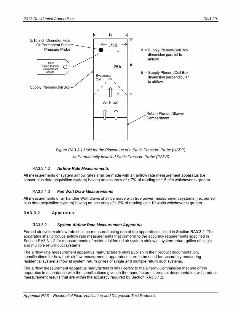
2013 Residential Appendices RA3-29
Appendix RA3 – Residential Field Verification and Diagnostic Test Protocols
Figure RA3.3-1 Hole for the Placement of a Static Pressure Probe (HSPP)
or Permanently Installed Static Pressure Probe (PSPP)
RA3.3.1.2 Airflow Rate Measurements
All measurements of system airflow rates shall be made with an airflow rate measurement apparatus (i.e., sensor plus data acquisition system) having an accuracy of ± 7% of reading or ± 5 cfm whichever is greater.
RA3.3.1.3 Fan Watt Draw Measurements
All measurements of air handler Watt draws shall be made with true power measurement systems (i.e., sensor plus data acquisition system) having an accuracy of ± 2% of reading or ± 10 watts whichever is greater.
RA3.3.2 Apparatus
RA3.3.2.1 System Airflow Rate Measurement Apparatus
Forced air system airflow rate shall be measured using one of the apparatuses listed in Section RA3.3.2. The apparatus shall produce airflow rate measurements that conform to the accuracy requirements specified in Section RA3.3.1.2 for measurements of residential forced air system airflow at system return grilles of single and multiple return duct systems.
The airflow rate measurement apparatus manufacturers shall publish in their product documentation, specifications for how their airflow measurement apparatuses are to be used for accurately measuring residential system airflow at system return grilles of single and multiple return duct systems.
The airflow measurement apparatus manufacturers shall certify to the Energy Commission that use of the apparatus in accordance with the specifications given in the manufacturer's product documentation will produce measurement results that are within the accuracy required by Section RA3.3.1.2.
B
A
Air Flow
Evaporator Coil
.75A
.75BA = Supply Plenum/Coil Box
dimension parallel to airflow.
B = Supply Plenum/Coil Box dimension perpendicular to airflow.
Return Plenum/Blower Compartment
Supply Plenum/Coil Box
Title 24 Supply Plenum Measurement
Access
5/16 inch Diameter HoleOr Permanent Static
Pressure Probe

2013 Residential Appendices RA3-30
Appendix RA3 – Residential Field Verification and Diagnostic Test Protocols
For the airflow measurement apparatuses that are certified to the Commission as meeting the accuracy required by Section RA3.3.1.2, the following information will be posted on the Energy Commission website, making the information available to all people involved in the airflow verification compliance process:
(a) The product manufacturers' model numbers for the airflow measurement apparatuses.
(b) The product manufacturers' product documentation that gives the specifications for use of the airflow measurement apparatuses to accurately measure residential system airflow at system return grilles of single and multiple return duct systems.
A manufacturer's certification to the Commission of the accuracy of the airflow measurement apparatus, and submittal to the Commission of the product documentation that specifies the proper use of the airflow measurement apparatus to produce accurate airflow rate measurements shall be prerequisites for allowing the manufacturer's airflow measurement apparatus to be used for conducting the system airflow verification procedures in Section RA3.3 for demonstrating compliance with Part 6.
RA3.3.2.1.1 Fan Flowmeter
The apparatus for measuring the system airflow rate shall consist of a duct pressurization and airflow measurement device (subsequently referred to as a fan flowmeter) that meets all applicable instrumentation specifications in Section RA3.3.1, and a static pressure measurement device that meets the specifications in Section RA3.3.1.1. The fan flowmeter shall be attached at the inlet to a return duct from the conditioned space. If the system is not a multi-zoned automatic dampered system, the fan flowmeter may be attached at the air handler blower compartment door as an alternative to placement at the inlet to a return duct from conditioned space. The fan flowmeter shall be attached at a point where all the airflow through the system will flow through it. When the air handler blower compartment door attachment alternative is used, an air barrier must be placed between the return duct system and the air handler inlet(s). All registers shall be in their normal operating condition. The static pressure probe shall be fixed to the supply plenum at the location specified in Section RA3.3.1.1 so that it is not moved during this test.
RA3.3.2.1.2 Flow Grid
The apparatus for measuring the system airflow rate shall consist of a flow measurement device (subsequently referred to as a flow grid) that meets all applicable instrumentation specifications in RA3.3.1 and a digital pressure measurement device that meets the specifications in Section RA3.3.1.1. The flow grid shall be attached at a point where all the fan airflow will flow through the flow grid. All registers shall be in their normal operating condition. The static pressure probe shall be fixed to the supply plenum at the location specified in Section RA3.3.1.1 so that it is not moved during this test.
RA3.3.2.1.3 Powered Flow Capture Hood
A powered and pressure balanced flow capture hood (subsequently referred to as a Powered Flow Hood1) that has the capability to balance the flow capture static pressure difference between the room and the flow capture hood enclosure to 0.0 ± 0.2 Pa (.0008 inches water) and meets the applicable instrumentation specifications in Section RA3.3.1 may be used to verify the system airflow rate at the return grille(s) if the powered flow hood has a flow capture area at least as large as the return grille in all dimensions. The fan adjustment needed to balance the flow capture static pressure difference between the room and the flow capture hood enclosure to 0.0 ± 0.2 Pa (.0008 inches water) shall be provided by either an automatic control or a manual control operated in accordance with the apparatus manufacturer's instructions specified in the manufacturer's product documentation. All supply registers shall be in their normal operating position. Measurement(s) shall be taken at the return grille(s).
1 Also known as "active" flow hood, or "fan assisted" flow hood.

2013 Residential Appendices RA3-31
Appendix RA3 – Residential Field Verification and Diagnostic Test Protocols
RA3.3.2.1.4 Traditional Flow Capture Hood
A traditional flow capture hood2 meeting the applicable instrumentation specifications in Section RA3.3.1 may be used to verify the system airflow rate at the return grille(s) if the device has a capture area at least as large as the return grille in all dimensions. All registers shall be in their normal operating position. Measurement(s) shall be taken at the return grille(s).
RA3.3.2.2 Air Handler Watt Draw Measurement Apparatus
The air handler watt draw shall be measured using one of the following apparatuses.
RA3.3.2.2.1 Portable Watt Meter
The apparatus for measuring the air handler watt draw shall consist of a wattmeter meeting the applicable instrumentation specifications in RA3.3.1. The measuring device shall be attached to measure the air handler fan watt draw. All registers and blower access panel(s) shall be in their normal operating condition.
RA3.3.2.2.2 Utility Revenue Meter
The apparatus for measuring the air handler watt draw shall consist of the utility revenue meter meeting the applicable instrumentation specifications in RA3.3.1 and a stopwatch that provides measurements in units of seconds. All registers and blower access panel(s) shall be in their normal operating condition.
RA3.3.2.2.3 Digital Utility Revenue Meter
The apparatus for measuring the air handler watt draw shall consist of the digital utility revenue meter meeting the applicable instrumentation specifications in RA3.3.1 that provides direct digital display of the Watt draw. All registers and blower access panel(s) shall be in their normal operating condition.
RA3.3.3 Procedures
RA3.3.3.1 System Airflow Rate Measurement Procedures
When required for compliance, the installed system's airflow shall be diagnostically tested using one of the methods specified in this section.
For systems utilizing an intentional ducted ventilation airflow from outside the conditioned space into the return system, the outside airflow may be included in the system airflow if that flow occurs in all operating modes of the HVAC system.
For multi-zone systems the airflow must be measured for each and every operating mode of the system. This must be accomplished without bypasses from the supply ductwork to the return ductwork. All airflow measurements shall be performed with the fan set at the speed used for air conditioning.
Diagnostic system airflow rate measurement values shall be converted to fan cfm/ton by dividing the measured system airflow rate (Qah) by the nominal tons of condensing unit cooling capacity for the air conditioner.
The measured airflow rate shall be expressed in cubic feet per minute of standard air (standard air has a density of 0.075 lb/ft³). When the airflow measurement is made at altitudes significantly different from sea level or at temperatures significantly different from 70°F, the airflow indicated on the device gauge may differ from the standard CFM by as much as 15 percent. Corrections from indicated to standard CFM shall be made using the procedure specified by the airflow measurement device manufacturer.
RA3.3.3.1.1 System Airflow Rate Measurement Using Plenum Pressure Matching and Fan Flowmeter
This system airflow measurement shall be performed using the following procedures:
2 also known as "non-powered" flow hood, "standard" flow hood, "commercially available" flow hood, or "passive" flow hood

2013 Residential Appendices RA3-32
Appendix RA3 – Residential Field Verification and Diagnostic Test Protocols
(a) If the fan flowmeter is to be connected to the air handler outside the conditioned space, then the door or access panel between the conditioned space and the air handler location shall be opened.
(b) With the system fan on at the maximum speed used in the installation (the cooling speed when air conditioning is present), measure the pressure difference (in Pa) between the supply plenum and the conditioned space (Psp). Psp is the target pressure to be maintained during the system airflow tests. Place the pressure probe in the Supply Pressure Measurement Location described in Section RA3.3.1.1. Adjust the probe to achieve the highest pressure and then firmly attach the probe to ensure that it does not move during the system airflow test.
(c) If the fan flowmeter is to be connected to the air handler at the access, block the return duct system from the plenum upstream of the air handler fan and the fan flowmeter. Filters are often located in an ideal location for this blockage.
(d) Attach the fan flowmeter to the duct system at the inlet to one return duct from the conditioned space with the grille and filter removed (if there is more than one system return grille, block off all return grilles other than the one used for this measurement. Alternatively the fan flowmeter may be placed at the air handler.
(e) Turn on the system fan and the fan flowmeter, adjust the fan flowmeter until the pressure between supply plenum and conditioned space matches Psp.
(f) Record the flow through the fan flowmeter (Qah, cfm) - this is the diagnostic system airflow. In some systems, system fan and fan flowmeter combinations may not be able to produce enough flow to reach Psp. In this case record the maximum flow (Qmax, cfm) and pressure (Pmax) between the supply plenum and the conditioned space. The following equation shall be used to correct measured system flow and pressure (Qmax and Pmax) to operating condition at operating pressure (Psp).
Equation RA3.3-1 Air Handler Flow Qah = Qmax x (Psp/Pmax) ^0.5
RA3.3.3.1.2 System Airflow Rate Measurement Using Flow Grid
The system airflow measurement shall be performed using the following procedures:
(a) With the system fan on at the maximum speed used in the installation (the cooling speed when air conditioning is present), measure the pressure difference (in Pa) between the supply plenum and the conditioned space (Psp). Place the pressure probe in the Supply Pressure Measurement Location described in Section RA3.3.1.1. Adjust the probe to achieve the highest pressure and then firmly attach the probe to ensure that it does not move during the system airflow test.
(b) The flow grid shall be attached at a point where all the system air flows through the flow grid. If there are multiple return grilles in the duct system, flow grids may be used to measure airflow at the return grilles, but only by installing a flow grid in each return grill and making simultaneous measurements of all return grill airflows.
(c) Re-measure the system operating pressure with the flow grid in place.
(d) Measure the airflow through the flow grid (Qgrid) and the test pressure (Ptest). If multiple flow grids are used Qgrid is the sum of the flows through each of the flow grids.
(e) The following equation for air handler flow shall be used to correct flow through the flow grid and pressure (Qgrid and Ptest) to operating condition at operating pressure (Psp).
Equation RA3.3-2 Air Handler Flow Qah = Qgrid x (Psp/Ptest) ^0.5
RA3.3.3.1.3 System Airflow Rate Measurement Using Powered Flow Capture Hood
The system airflow measurement shall be performed using the following procedures; all registers shall be fully open, and the air filter shall be installed. Turn on the system fan at the cooling speed and measure the airflow at the return grille(s) with a calibrated powered flow hood to determine the total system return airflow. Operation of the powered flow hood shall conform to the specifications in the manufacturer's product documentation. For

2013 Residential Appendices RA3-33
Appendix RA3 – Residential Field Verification and Diagnostic Test Protocols
multiple return systems, the total system return airflow (Qah, cfm) shall be the sum of the airflow measurements at each of the system's return grilles.
RA3.3.3.1.4 System Airflow Rate Measurement Using Traditional Flow Capture Hood
The system airflow measurement shall be performed using the following procedures; all registers shall be fully open, and the air filter shall be installed. Turn on the system fan at the cooling speed and measure the airflow at the return grille(s) with a calibrated traditional flow capture hood to determine the total system return airflow. For multiple return systems, the total system return airflow (Qah, cfm) shall be the sum of the airflow measurements at each of the system's return grilles.
RA3.3.3.2 Air Handler Fan Watt Draw Measurement Procedures
The diagnostic air handler watt draw shall be measured using one of the following methods:
RA3.3.3.2.1 Air Handler Watt Draw Measurement Using Portable Watt Meter
The air handler watt draw measurement shall be performed using the following procedures; all registers shall be fully open, and the air filter shall be installed. Turn on the system fan at the maximum speed used in the installation (usually the cooling speed when air conditioning is present; usually the cooling speed with outdoor air introduction if ventilation is provided through the return duct system) and measure the fan watt draw (Wfan).
RA3.3.3.2.2 Air Handler Watt Draw Measurement Using Utility Revenue Meter
The air handler watt draw measurement shall be performed using the following procedures; all registers shall be fully open, and the air filter shall be installed. Turn on the system fan at the maximum speed used in the installation (usually the cooling speed when air conditioning is present; usually the cooling speed with outdoor air introduction if ventilation is provided through the return duct system) and turn off every circuit breaker except the one exclusively serving the air handler. Record the Kh factor on the revenue meter, count the number of full revolutions of the meter wheel over a period exceeding 90 seconds. Record the number of revolutions (Nrev) and time period (trev, seconds). Compute the air handler watt draw (Wfan) using the following formula:
Equation RA3.3-3 Air Handler Fan Watt Draw Wfan = (Kh x Nrev x 3600) / trev
Return all circuit breakers to their original positions.
RA3.3.3.2.3 Air Handler Watt Draw Measurement Using Digital Utility Revenue Meter
The air handler watt draw measurement shall be performed using the following procedures; all registers shall be fully open, and the air filter shall be installed. Turn on the system fan at the maximum speed used in the installation (usually the cooling speed when air conditioning is present; usually the cooling speed with outdoor air introduction if ventilation is provided through the return duct system) and turn off every circuit breaker except the one exclusively serving the air handler. Read the Watt draw from the digital utility meter digital display. Return all circuit breakers to their original positions.
RA3.3.3.3 Determination of Forced Air System Fan Efficacy Demonstrating compliance with fan efficacy requirements requires simultaneous measurement of the system airflow rate using Section RA3.3.3.1 procedures and fan Watt draw using Section RA3.3.3.2 procedures. The results of the simultaneous airflow rate and fan Watt draw measurements are used for calculation of a value for the forced air system fan efficacy as follows:
(a) The measured value for fan Watt draw (Watt) shall be divided by the measured value for airflow rate (cfm) to determine the fan efficacy (Watt/cfm).

2013 Residential Appendices RA3-34
Appendix RA3 – Residential Field Verification and Diagnostic Test Protocols
RA3.3.3.4 Determining Compliance with Fan Efficacy or System Airflow Requirements
Compliance with the requirements for improved airflow or for improved fan efficacy both require simultaneous measurement of airflow and fan Watts. The simultaneous measurements shall be used to calculate the following values used to determine compliance:
RA3.3.3.4.1 Airflow Calculation (cfm/ton)
The measured value for airflow (cfm) shall be converted to cfm per ton by dividing the measured system airflow rate by the nominal tons of condensing unit cooling capacity for the air conditioner.
RA3.3.3.4.2 Fan Efficacy Calculation (Watt/cfm)
The measured value for fan Watt draw (Watt) shall be divided by the measured value for airflow rate (cfm) to determine the fan efficacy (Watt/cfm).
RA3.3.3.4.3 Compliance Criteria
In order to comply with either the fan efficacy requirement, or the system airflow requirement, the following criteria shall be met:
(a) The system airflow (cfm/ton) shall meet or exceed the system airflow compliance criteria specified in the Standards or on the Certificate of Compliance as applicable.
(b) The calculated value for fan efficacy (Watt/cfm) shall be equal to or less than the fan efficacy compliance criterion specified in the Standards or on the Certificate of Compliance as applicable, and
(c) Single zone air distribution systems with multi-speed compressor systems or variable speed compressor systems shall verify air flow (cfm/ton) and fan efficacy (Watt/cfm) for system operation in cooling mode at the maximum compressor speed and the maximum air handler fan speed.
(d) Zoned air distribution systems shall meet both the airflow (cfm/ton) and fan efficacy (Watt/cfm) criteria in every zonal control mode, except that multi-speed compressor systems or variable speed compressor systems shall only be required to verify air flow (cfm/ton) and fan efficacy (Watt/cfm) for system operation in cooling mode at maximum compressor capacity and maximum system fan speed and with all zones calling for conditioning.
RA3.4 Field Verification of Installed HVAC System Components and Devices
RA3.4.1 Purpose and Scope
The purpose of these procedures is to verify that residential space cooling systems and heat pumps have the required components to achieve the energy efficiency claimed in the compliance documents. The procedures apply when a Charge Indicator Display (CID) is specified for split system equipment, or when an EER or SEER higher than the default is claimed. For dwelling units with multiple systems, the procedures shall be applied to each system separately.
The installer shall certify on the Certificate of Installation that the components required for compliance have been installed.
RA3.4.2 Charge Indicator Display (CID) Verification Procedure
The CID verification procedure shall consist of visual inspection to confirm that the CID is installed on the system, and that the manufacturer has certified to the Energy Commission that the CID model meets the applicable requirements of Reference Joint Appendix JA6. In addition, the space conditioning system shall comply with the procedures specified in Sections RA3.4.2.1, or RA3.4.2.2, or RA3.4.2.3.

2013 Residential Appendices RA3-35
Appendix RA3 – Residential Field Verification and Diagnostic Test Protocols
RA3.4.2.1 Verification of installation of a CID with "self diagnostic reporting" functionality when outdoor air temperature is less than 55F
The space conditioning system installer shall use the weigh-in charging procedure in Section RA3.2.3.1 to comply with refrigerant charge requirements. HERS verification compliance for the refrigerant charge requirement shall be satisfied by visual inspection to confirm the system has a CID installed, and confirming the installed CID "self diagnostic reporting function" indicates CID sensors and internal processes are operating within the CID device's specified design parameters.
RA3.4.2.2 Verification of Installation of a CID that does not have "self diagnostic reporting" functionality when outdoor air temperature is less than 55F
The space conditioning system installer shall use the weigh-in charging procedure in Section RA3.2.3.1 to comply with the refrigerant charge requirements, and HERS verification compliance for the refrigerant charge requirement shall be delayed until a time when the outdoor air temperature is equal to or greater than 55F, at which time the procedure in RA3.4.2.3 shall be performed.
RA3.4.2.3 Verification of Installation of a CID when the outdoor air temperature is equal to or greater than 55F
When the outdoor air temperature is warmer than 55F, the space conditioning system installer shall use either the standard charge verification procedure or the weigh-in charging procedure to comply with the refrigerant charge requirement, and HERS verification compliance for the refrigerant charge requirement shall be validation of the CID installation when the outdoor air temperature is warm enough for the installed CID to perform a valid refrigerant charge test according to the CID manufacturer specification. The HERS Rater verification shall consist of operating the air conditioner in cooling mode for at least 15 minutes and performing a visual inspection to verify the CID reports the system is operating within acceptable parameters, or otherwise reports a system fault. If the CID reports that there is a system fault, the system does not comply with the refrigerant charge verification requirement.
RA3.4.3 Time Delay Relay Verification Procedure
When a system rating specification includes a time delay relay, the installation of the time delay relay shall be verified.
The procedure shall be:
(a) Turn the thermostat down until the compressor and indoor fan are both running.
(b) Turn the thermostat up so the compressor stops running.
(c) Verify that the indoor fan continues to run for at least 30 seconds.
RA3.4.4 HVAC System Verification Procedures
This section defines procedures for field verification of installed HVAC systems.
RA3.4.4.1 Rated Space Conditioning System Equipment Verification Procedure
When installation of specific matched system equipment is necessary for compliance with requirements for higher than minimum values for system EER or SEER, the installed system equipment shall be verified by a HERS Rater. The verification shall utilize certified rating data from the AHRI Directory of Certified Product Performance at http://www.ahridirectory.org or another directory of certified product performance ratings approved by the Energy Commission for determining compliance.
The procedure shall consist of visual verification of installation of the following system equipment components and confirmation that the installed equipment matches the equipment required to achieve the required SEER or EER rating:

2013 Residential Appendices RA3-36
Appendix RA3 – Residential Field Verification and Diagnostic Test Protocols
(a) The specified labeled make and model number of the outdoor unit.
(b) The specified labeled make and model number of the inside coil.
(c) The specified labeled make and model of the furnace or air handler when a specific furnace or air handler is necessary to achieve the SEER or EER rating,
(d) The specified metering device when a specific refrigerant metering device (such as a TXV or an EXV) is necessary to achieve the high efficiency rating.
(e) When a system rating specification includes a time delay relay, the installation of the time delay relay shall be verified according to the procedure in Section 3.4.3.
RA3.4.4.2 Reserved
RA3.5 Quality Insulation Installation Procedures
RA3.5.1 Purpose and Scope
RA3.5 is a procedure for verifying the quality of insulation installation and air leakage control used in low-rise residential buildings. This procedure is to be followed by the insulation installer and a qualified Home Energy Rating System (HERS) rater must verify its conformance for meeting the requirements of Sections 150.1(c), and 110.7(a) and (b) of the Standards.
The procedure applies to wood and metal construction of framed and non-framed envelope assemblies. Framed assemblies include wall stud cavities, roof/ceiling assemblies, and floors typically insulated with: (1) batts of mineral fiber and mineral wool; (2) loose-fill materials of mineral fiber, mineral wool, and cellulose; (3) spray polyurethane foam; and, (4) rigid board sheathing materials. Non-framed assemblies include wall, roof/ceiling, and floors constructed of structural insulated panels and insulated concrete forms.
Note 1: This procedure applies to the entire thermal envelope of the building. In many instances, residential homes will use several types of insulation material, even in the same framed assembly. Each insulation material and the integrity of air leakage control for the building's entire thermal envelope must be verified by the HERS rater for the home to comply with the Standards.
Note 2: Structural bracing, tie-downs, and framing of steel or specialized framing used to meet structural requirements of the California Building Code (CBC) are allowed. These areas shall be called out on the building plans with diagrams and/or specific design drawings indicating the R-value amount and fastening method to be used. All structural framing areas shall be insulated in a manner that resists thermal bridging from the outside to the inside of the assembly separating conditioned from unconditioned space. The insulation and air barrier integrity shall be verified by the HERS rater.
RA3.5.2 Definitions
Continuous Air Barrier
A combination of interconnected materials and assemblies joined and sealed together to provide a continuous barrier to air leakage through the building envelope separating conditioned from unconditioned space, or adjoining conditioned spaces of different occupancies or uses. An air barrier is required in all thermal envelope assemblies to limit air movement between unconditioned/outside spaces and conditioned/inside spaces and must meet one of the following:
1. Using individual materials that have an air permeance not exceeding 0.004cfm/ft2 under a pressure differential of 0.3in. w.g. (1.57psf) (0.02 L/s.m2 at 75 pa) when tested in accordance with ASTM E2178; or
2. Using assemblies of materials and components that have an average air leakage not to exceed 0.04 cfm/ft2 under a pressure differential of 0.3 in. w.g (1.57psf) (0.2 L/s.m2 at 75 pa)

2013 Residential Appendices RA3-37
Appendix RA3 – Residential Field Verification and Diagnostic Test Protocols
when tested in accordance with ASTM E2357, ASTM E1677, ASTM E1680 or ASTM E283; or
3. Testing the completed building and demonstrating that the air leakage rate of the building envelope does not exceed 0.40 cfm/ft2 at a pressure differential of 0.3 in w.g. (1.57 psf) (2.0 L/s.m2 at 75 pa) in accordance with ASTM E779 or an equivalent approved method.
Individual materials and assemblies of materials that can demonstrate compliance with the air barrier testing requirements must be installed according to the manufacturer's instructions and a HERS rater shall verify the integrity of the installation. Below are example materials meeting the air permeance testing performance levels of 1 above. Manufacturers of these and other product types must provide a specification or product data sheet showing compliance to the ASTM testing requirements to be considered as an air barrier.
-- Plywood – minimum 3/8 inch
-- Oriented strand board – minimum. 3/8 inches
-- Extruded polystyrene insulation board – minimum. ½ inch
-- Foil-back polyisocyanurate insulation board – minimum. ½ inch
-- Extruded polystyrene insulation board – minimum ½ inch
-- Foil backed urethane foam insulation (1 inch)
-- Closed cell spray polyurethane foam with a minimum density of 2.0 pcf and a minimum thickness of 2.0 inches
-- Open cell spray polyurethane foam with a minimum density of 0.4 to1.5 pcf and a minimum thickness of 5½ inches
-- Exterior or interior gypsum board - minimum 1/2 inch
-- Cement board - minimum 1/2 inch
-- Built up roofing membrane
-- Modified bituminous roof membrane
-- Particleboard-minimum1/2 inch
-- Fully adhered single-ply roof membrane
-- Portland cement/sand parge ,or gypsum plaster minimum 5/8 inch
-- Cast-in-place and precast concrete.
-- Fully grouted uninsulated and insulated concrete block masonry
-- Sheet steel or aluminum
Air-tight Limiting the passage of air either in or out of the building envelope.
Note: Thermal envelope assemblies (such as wall assemblies) shall be built to minimize air movement. Air movement brings unconditioned air and moisture through or into the assembly. For these procedures, air-tight shall be defined as an assembly or air barrier with all openings caulked, or sealed with minimally expansive foam, or taping/sealing of adjoining surfaces of air barrier materials and assemblies.
Compression Compacting of insulation in an assembly that results in elimination of the air pockets trapped in the material that gives the insulation its R-value per inch. Batt insulation should be “lofted” and loose-fill and spray foam material properly field applied to the manufacturer specified density to achieve its full R-value. Limited compression is allowed at plumbing, vents, and other obstructions and in cavities of non-standard framing. Compression of insulation in these situations by more than 50% is excessive and shall not be allowed.

2013 Residential Appendices RA3-38
Appendix RA3 – Residential Field Verification and Diagnostic Test Protocols
Delaminated Separation of the insulation's full thickness to facilitate it's installation around or between obstructions. Batt and blanket insulation are often split or delaminated to fit around electrical wires and plumbing runs through a wall cavity. The delamination must ensure that the full thickness of the insulation is installed between the obstruction and the finish material covering the framing. For example, an electrical wire located one-third of the distance from the front of the cavity should have batt insulation delaminated so that two-thirds of the batt is installed towards the outside wall surface and one-third is installed towards the inside wall surface from the wire.
Draft Stops
A material, device or construction installed to prevent the movement of air within open spaces of concealed areas of building components, such as crawl spaces, floor/ceiling assemblies, wall assemblies, roof/ceiling assemblies and attics.
Note: Draft stops are important components of the air barrier and shall be air-tight. Fire blocks constructed of porous insulation materials cannot serve as draft stops since they are not air tight.
Friction Fit A means of attaching insulation within the framed cavity without the use of mechanical fasteners such that the material's full thickness in all directions is sufficient to maintain its installation integrity. In standard framing dimensions of 2x4' and 2x6" @ 16" oc and 24" oc batt and blanket insulation materials have enough side-to-side frictional force to hold the insulation in place without any other means of attachment.
Note: Friction fitting of faced batt and blanket insulation, with or without an attachment flange, is allowed provided the insulation's installation integrity can be maintained.
Gaps Uninsulated areas at the edge of insulation where insulation is not in contact with framing members or other materials at the edge of the insulation. Gaps occur when insulation length and width is too short for the cavity. Gaps in insulation are avoidable and are not permitted.
Hard Covers Building materials, such as plywood or gypboard, which become part of the ceiling air barrier.
Note: Hard covers shall be installed above areas where there is a drop ceiling. For example, a home with 10ft ceilings may have an entry closet with a ceiling lowered to 8ft. In this case, a hard cover is installed at the 10ft level above the entry closet. Hard covers become part of the ceiling air barrier and shall be air-tight.
Inset Stapling A method of attaching faced batt or blanket insulation to wood framing. The flange of the insulation facing is pushed inside the face of the framing member and stapled as opposed to In windy areas installers often staple the flanges of faced batts to the sides of the stud in order to assure that the insulation remains in place until covered with drywall, particularly on the wall between the house and the garage where there isn't any exterior sheathing to help keep the insulation in place. The void created by the flange inset shall not extend more than two inches from the stud on each side.
Insulation Types--framed assemblies
There are four basic types of insulation, or insulation "systems", installed in residential buildings and their use varies based on the design and type of construction:
1. Batt and Blanket: Batt and blanket insulation is made of mineral fiber and mineral wool -- either processed fiberglass, rock or slag wool -- and is used to insulate below floors, above ceilings, below roofs, and within walls.
2. Loose-fill: Loose-fill insulation includes loose fibers or fiber pellets that are blown into building cavities or attics using special equipment. Loose-fill insulations typically are produced using mineral fiber, mineral wool, or cellulose. They are installed in walls, floors, attics and below roofs using a dry-pack process or a moist-spray technique, and may include a netting material.
3. Rigid Board: Rigid board insulation sheathing is made from fiberglass, expanded polystyrene (EPS), extruded polystyrene (XPS), polyisocyanurate, or polyurethane. This type of insulation is used for above roof decks, exterior walls, cathedral ceilings, basement walls, as perimeter insulation at concrete slab edges, and to insulate special framing situations such as window and door headers, and around metal seismic bracing. Rigid board insulation may also

2013 Residential Appendices RA3-39
Appendix RA3 – Residential Field Verification and Diagnostic Test Protocols
be integral to exterior siding materials.
4. Spray Polyurethane Foam (SPF): A two-part liquid foamed plastic (such as polyurethane or modified urethane) material formed by the reaction of an isocyanurate and a polyol that uses a blowing agent to develop a cellular structure when spray applied onto a substrate. SPF insulation is a two-component reactive system mixed at a spray gun or a single-component system that cures by exposure to humidity. The liquid is sprayed through a nozzle into wall, roof/ceiling, and floor cavities. SPF insulation can be formulated to have specific physical properties (i.e., density, compressive strength, fire resistance and R-value). There are two types of SPF insulation:
a. Low Density Open-Cell SPF (ocSPF) Insulation: A spray applied polyurethane foam insulation having an open cellular structure resulting in an installed nominal density of 0.4 to 1.5 pounds per cubic foot (pcf).
b. Medium Density Closed-Cell SPF (ccSPF) Insulation: A spray applied polyurethane foam insulation having a closed cellular structure resulting in an installed nominal density of greater than 1.5 to less than 2.5 pounds per cubic foot (pcf).
Insulation Types--non-framed assemblies
There are two basic types of insulation used and their use varies based on the design and type of construction:
1. Structural Insulated Panel (SIP): A composite building material consisting of an insulating layer of rigid polymer foam sandwiched between two layers of structural board. The board can be sheet metal, plywood, cement or oriented strand board (OSB) and the foam is either expanded polystyrene foam (EPS), extruded polystyrene foam (XPS) or polyurethane foam. SIPs combine several components of conventional building, such as studs and joists, insulation, vapor barrier and air barrier. They can be used for many different applications, such as exterior walls, roofs, floors, and foundation systems.
2. Insulated Concrete Form (ICF): A system of formwork for concrete that stays in place as permanent building insulation and is used for cast-in-place, reinforced above and below-grade concrete walls, floors, and roofs. ICFs are interlocking modular units that can be dry-stacked (without mortar) and filled with concrete as a single concrete masonry unit (CMU). ICFs lock together externally and have internal metal or plastic ties to hold the outer layer(s) of insulation to create a concrete form for the structural walls, roof/ceilings, or floors of a building. ICFs are manufactured from several materials including: expanded and extruded polystyrene foam, polyurethane foam, cement-bonded wood fiber, and cement-bonded polystyrene beads.
Minimally Expansive Foam Sealing Material
A single-component polyurethane foam system typically formulated in a handheld can or portable container to seal and fill construction gaps and crevasses, holes, and cracks without distorting adjacent framing. These materials are not used for insulation purposes, rather as agents for air sealing of gaps and crevasses that are too small to be insulated.
Net Free-Area
The net free-area of a vent cover is equal to the total vent opening less the interference to air flow caused by a screen or louver used for ventilation. Screened or louvered vent opening covers are typically marked by the manufacturer with the "net free-area." For example a 22.5 in. by 3.5 in. eave vent screen with a total area of 78.75 square inches may have a net free-area of only 45 square inches.
Voids & Air Spaces
An uninsulated space within an enclosed building assembly created where the assembly has been insulated by partial filling of the framed cavity. The partial fill results in an air space (void) between the insulation surface and the assembly’s exterior or interior layers which form the assembly’s air barrier.

2013 Residential Appendices RA3-40
Appendix RA3 – Residential Field Verification and Diagnostic Test Protocols
RA3.5.3 BATT AND BLANKET INSULATION
These procedures detail the installation and inspection protocols necessary to qualify for Quality Insulation Installation (QII) of batt and blanket insulation. These procedures must be field verified before the building construction permit is finalized in order to claim QII energy compliance.
These procedures are to be followed by the insulation installer and a qualified Home Energy Rating System (HERS) rater must verify its conformance to meet the requirements of Sections 150.1(c), and 110.7(a) and (b) of the Standards.
RA3.5.3.1 Thermal Specification
This insulation type is manufactured in different widths, lengths, and thicknesses and is available with or without a facing. Faced batts and blanket insulation material are also available with or without an attachment flange. Specific product R-values are readily available from the manufacturer for the specific materials being installed and the R-value of the product is marked on the face of the product (faced or unfaced material). The installed insulation must meet the R-value stated on the compliance documentation.
RA3.5.3.1.1 Requirements for Walls, Roof/Ceilings and Floors
(a) Materials shall comply with, and be installed in conformance with, all applicable building codes for building. California Building Code (including, but not limited to, California Electric Code Section 719) and installed to meet all applicable fire codes.
(b) Materials shall meet California Quality Standards for Insulating Material, Title 24, Part 12, Chapter 4, Article 3, listed in the California Department of Consumer Affairs Consumer Guide and Directory of Certified Insulating Materials.
(c) Materials shall comply with flame spread rating and smoke density requirements of Chapter 26 and Section 706 of the Title 24, Part 2: all installations with exposed facings must use fire retardant facings which have been tested and certified not to exceed a flame spread of 25 and a smoke development rating of 450. Insulation facings that do not touch a ceiling, wall, or floor surface, and faced batts on the undersides of roofs with an air space between the ceiling and facing are considered exposed applications.
(d) Materials shall be installed according to manufacturer specifications and instructions.
(e) Batt and blanket insulation shall be correctly sized to fit snugly at the sides and ends.
(f) Batt and blanket insulation shall be installed so that they will be in contact with the air barrier.
(g) Where necessary, batt and blanket insulation shall be cut to fit properly - there shall be no gaps, nor shall the insulation be doubled-over or compressed.
(h) When batt and blanket insulation are cut to fit a non-standard cavity, they shall be snuggly fitted to fill the cavity without excessive compression.
(i) Batt and blanket insulation shall be cut to butt-fit around wiring and plumbing, or be split (delaminated) so that one layer can fit behind the wiring or plumbing, and one layer fit in front.
(j) For batts and blanket insulation that is taller than the trusses, full-width batts shall be used so that they expand to touch each other over the trusses.
(k) Hard covers or draft stops shall be placed over all drop ceiling areas and interior wall cavities to keep insulation in place and stop air movement. If hard covers or draft stops are missing or incomplete, they shall be completed before insulation is installed.
(l) Required eave ventilation shall not be obstructed - the net free-ventilation area of the eave vent shall be maintained.
(m) Eave vent baffles shall be installed to prevent air movement under or into the batt.

2013 Residential Appendices RA3-41
Appendix RA3 – Residential Field Verification and Diagnostic Test Protocols
(n) Insulation shall cover all recessed lighting fixtures. If the fixtures are not rated for insulation cover (IC) and air tight, the fixtures shall be replaced.
All recessed light fixtures that penetrate the ceiling shall be listed for zero clearance insulation contact (IC), have a label that certifies it as airtight with leakage less than 2.0 cfm @ 75 Pa when tested to ASTM E283, and shall be sealed with a gasket or caulk between the light's housing and the ceiling.
RA3.5.3.1.2 R-value Measurement Equipment
The HERS rater shall verify the installed thickness of insulation in all assemblies and locations on walls, roof/ceilings, and floors, and to ensure that insulation levels and installation integrity meet the R-value specified on the Certificate of Compliance, and all other required compliance documentation.
RA3.5.3.1.3 Certificates
All provisions of Residential Appendix RA2 shall be met. An Insulation Certificate of Installation signed by the insulation installer shall be provided that states the installation is consistent with the plans and specifications for which the building permit was issued. The certificate shall also state the installing company name, insulation company and manufacturer's name and material identification, and the installed R-value. The insulation installer shall also complete the applicable sections of the Certificate of Installation form and attach a product specification or data sheet for every insulation material used.
RA3.5.3.1.4 Certificates and Availability
All provisions of Residential Appendix RA2 shall be met. The Insulation Certificate of Installation, with insulation material labels or specification/data sheets attached, signed by the insulation installer, shall be available on the building site for each of the HERS rater's verification inspections. Note: The HERS rater cannot verify compliance credit without these completed forms.
RA3.5.3.2 Wall Insulation
(a) Wall stud cavities shall be caulked or foamed to provide a substantially air-tight envelope to the outdoors, attic, garage and crawl space. All plumbing and wiring penetrations through the top and bottom plates and electrical boxes that penetrate the sheathing shall be sealed. All gaps in the air barrier shall be caulked, taped, or sealed with minimally expansive foam.
(b) Bottom plates of framed and non-framed assemblies shall be sealed to the ground subfloor or slab, and above ground subfloor.
(c) Insulation shall uniformly fill the cavity side-to-side, top-to-bottom, and front-to-back.
(d) Batt insulation shall fill the cavity by friction fitting, inset or face stapling of flanges of faced batts, or by other support methods as necessary.
(e) Batt and blanket insulation shall be installed to fill the cavity and be in contact with the sheathing on the back and the wallboard on the front - no gaps or voids.
(f) Batts with flanges that are inset stapled to the side of the stud must be flush with the face of the cavity (or protrude beyond) except for the portion that is less than two inches from the edge of the stud.
(g) Non-standard-width cavities shall be filled with insulation fitted into the space without excessive compression.
(h) Batt insulation shall be cut to butt-fit around wiring and plumbing, or be split (delaminated) so that one layer can fit behind the wiring or plumbing, and one layer fit in front.
RA3.5.3.2.1 Narrow-Framed Cavities
(a) Non-standard width cavities shall be filled with insulation to snuggly fit into the space, or with minimally expansive foam sealing material.

2013 Residential Appendices RA3-42
Appendix RA3 – Residential Field Verification and Diagnostic Test Protocols
(b) Narrow spaces less than 1 inch in width at windows and door jambs, shall be filled with minimally expansive foam sealing.
(c) Narrow spaces less than 2 inches in width, such as between studs at building corners, and at the intersection of interior partition walls to exterior walls, shall be filled with insulation snuggly fitted in the space, or with minimally expansive foam sealing.
RA3.5.3.2.2 Special Situations--Installation Prior to Exterior Sheathing or Lath
(a) Hard to access wall stud cavities, such as corner channels, wall intersections, and behind tub/shower enclosures shall be insulated to the proper R-value. In most cases this can only be completed prior to the installation of the tub/shower enclosure, the exterior sheathing, or the exterior stucco lath.
(b) An air barrier shall be installed on the inside of the exterior wall(s) directly adjacent to the tub/shower enclosure.
RA3.5.3.2.3 Special Situations--Obstructions
(a) Insulation shall be cut to fit around wiring and plumbing without compression.
(b) Insulation shall be placed between the sheathing and the rear of electrical boxes and phone boxes.
(c) In cold climates, where water pipes may freeze (such as Climate Zones 2, 11-14 and 16) pipes shall have at least 1/2 of the insulation between the water pipe and towards the outside surface of the exterior wall. If the pipe is closer to the exterior finish assembly layers, as much insulation as possible shall be placed between the pipe and the outside (without excessive compression), and remaining insulation shall be placed between the pipe and the interior assembly material.
RA3.5.3.2.4 Special Situations--Rim Joists
(a) All rim-joists shall be insulated to the same R-value as the adjacent walls.
(b) The insulation shall be installed without gaps, voids, or compression.
RA3.5.3.2.5 Special Situations--Kneewalls, Skylight Shafts, and Gable Ends
(a) Framing for kneewalls, skylight shafts and gable ends that separate conditioned from unconditioned space shall be insulated to meet or exceed the wall R-value specified on the Certificate of Compliance, and all other required compliance documentation.
(b) The insulation shall be installed without gaps and with minimal compression.
(c) For steel-framed kneewalls, skylight shafts, and gable ends, external surfaces of steel studs shall be covered with insulation unless otherwise specified on the Certificate of Compliance using correct U-factors from Joint Appendix JA4, Table 4.3.4 (or U-factors approved by the Commission Executive Director).
(d) The backside of air permeable insulation exposed to the unconditioned attic space shall be completely covered with rigid board insulation or an air barrier.
(e) The house side of the insulation shall be in contact with the drywall or other wall finish.
(f) The insulation shall be supported so that it will not fall down by either friction fitting to the framing, inset or face stapling of flanges, or using other support such as netting.
(g) Insulation for all kneewall and skylight shafts shall be completely enclosed by vertical and horizontal framing, including horizontal plates at top and bottom of the insulation.
(h) In unvented attics, where insulation is applied directly to the underside of the roof deck, kneewalls, skylight shafts, and gable ends shall be insulated to meet or exceed the wall R-value specified on the Certificate of Compliance, and all other required compliance documentation.

2013 Residential Appendices RA3-43
Appendix RA3 – Residential Field Verification and Diagnostic Test Protocols
RA3.5.3.2.6 Special Situations--HVAC/Plumbing Closet
Walls of interior closets for HVAC and/or water heating equipment, which require combustion air venting, shall be insulated to the same R-value as the exterior walls as specified in compliance documentation.
RA3.5.3.2.7 Special Situations--Double Walls and Framed Bump-Outs
(a) Insulation shall fill the entire cavity; or, an additional air barrier shall be installed inside the double wall or bump-out and in contact with the insulation so that the insulation fills the cavity formed with the additional air barrier.
(b) Entire double walls and framed bump-outs shall be air-tight.
RA3.5.3.2.8 Special Situations--Structural Bracing, Tie-downs, Steel Structural Framing
(a) Framing and bracing used for structural purposes shall be identified on plan documents with diagrams and/or design drawings.
(b) Insulation shall be installed in a manner that restricts thermal bridging through the structural framing assembly.
(c) Insulation shall be applied to fully enclose and/or adhere to all sides and ends of structural assembly framing that separate conditioned from unconditioned space.
(d) The structural portions of assemblies shall be air-tight.
RA3.5.3.2.9 Special Situations--Window and Door Headers
All window and door headers shall be insulated to a minimum of R-2 between the exterior face of the header and inside surface of the finish wall material.
RA3.5.3.3 Roof/Ceilings
(a) Batt and blanket insulation shall be correctly sized to fit snugly at the sides and ends.
(b) Batt and blanket insulation shall be installed to be in contact with the air barrier.
(c) Where necessary, batt and blanket insulation shall be cut to fit properly - there shall be no gaps, nor shall the insulation be doubled-over or compressed.
(d) When batt and blanket insulation are cut to fit a non-standard cavity, they shall be snuggly fitted to fill the cavity without compression.
(e) Batt and blanket insulation shall be cut to butt-fit around wiring and plumbing, or be split (delaminated) so that one layer can fit behind the wiring or plumbing, and one layer fit in front.
(f) Batt and blanket insulation that is thicker than truss depth shall be installed so that the insulation expands to touch adjoining cavity over each truss member.
(g) Hard covers or draft stops shall be placed over all drop ceiling areas and interior wall cavities to keep insulation in place and stop air movement. If hard covers or draft stops are missing or incomplete, they shall be completed before insulation is installed.
(h) Baffles shall be placed at eaves or soffit vents of vented attics to keep insulation from blocking eave ventilation and prevent air movement under the insulation. The required net free-ventilation shall be maintained.
(i) All recessed light fixtures that penetrate the ceiling shall be listed for zero clearance insulation contact (IC), have a label that certifies it as airtight with leakage less than 2.0 cfm @ 75 Pa when tested to ASTM E283, and shall be sealed with a gasket or caulk between the light's housing and the ceiling.
(j) Insulation shall cover all recessed lighting fixtures. Fixtures that are not rated for insulation cover (IC), and air-tight, shall be replaced.

2013 Residential Appendices RA3-44
Appendix RA3 – Residential Field Verification and Diagnostic Test Protocols
RA3.5.3.3.1 Special Situations--Enclosed Rafter Ceilings
(a) An air space shall be maintained between the insulation and roof sheathing per California Building Code, Sections 1203.2 and R806.3, or as specified by the local building department.
(b) Facings and insulation shall be kept away from combustion appliance flues in accordance with flue manufacturers' installation instructions or labels on the flue.
(c) Insulation installed in unvented rafter ceilings or to the underside of unvented roofs with an attic below shall have an R-value conforming to compliance documentation and the air barrier shall be uniform across the transition of roof to wall. The insulation shall be in contact with the air barrier.
RA3.5.3.3.2 Special Situations--Attics and Cathedral Ceilings
In unvented attics, where insulation is applied directly to the underside of the roof deck, all gable ends shall be insulated to the same R-value as the exterior walls as specified in the compliance documentation.
RA3.5.3.3.3 Special Situations--HVAC Platform
(a) Batt and blanket insulation shall be placed below any platform or cat-walk for HVAC equipment installation and access.
(b) Batt and blanket insulation shall be installed so that they will be in contact with the air barrier.
RA3.5.3.3.4 Special Situations--Attic Access
Permanently attach rigid board insulation or batt or blanket insulation with the appropriate R-value to the access door using adhesive or mechanical fastener. The bottom of the attic access shall be gasketed to prevent air leakage of conditioned air to the unconditioned attic.
RA3.5.3.4 Raised Floors
(a) Batt and blanket insulation shall be correctly sized to fit snugly at the sides and ends.
(b) Batt and blanket insulation shall be cut to fit properly without gaps. Insulation shall not be doubled-over or compressed.
(c) Batt and blanket insulation shall be in contact with the air barrier - usually the subfloor.
RA3.5.3.4.1 Homes with Floors Over Garage
(a) Batt and blanket insulation shall be correctly sized to fit snugly at the sides and ends, but not be so large as to buckle.
(b) Batt and blanket insulation shall be cut to fit properly without gaps. Insulation shall not be doubled-over or compressed.
(c) Batt and blanket insulation shall be in contact with the air barrier - usually the subfloor.
(d) On floors that are over garages, or where there is an air space between the insulation and the subfloor, the rim joist shall be insulated.
(e) Batt and blanket insulation shall be cut to butt-fit around wiring and plumbing, or be split (delaminated) so that one layer can fit behind the wiring or plumbing, and one layer fit in front.
(f) Faced batts or blankets shall be placed toward the living space and be in contact with the underside of the floor sheathing. Continuous support shall be provided to keep the facing in contact with the floor sheathing. The insulation shall be properly supported by stapling of flanges, netting or other method approved by the manufacturer for the product.
(g) Batt and blanket insulation shall be properly supported to avoid gaps, voids, and compression.

2013 Residential Appendices RA3-45
Appendix RA3 – Residential Field Verification and Diagnostic Test Protocols
RA3.5.3.4.2 Homes with Conditioned Space Over Garage
The floor over the garage shall be insulated with batt or blanket insulation against the subfloor of the conditioned space. The garage and the adjacent conditioned space (house) shall be insulated up to the subfloor. All rim and band joists adjoining conditioned space shall be air tight and insulated.
Figure RA3.5-1 Homes with Conditioned Space Over Garage – Batt and Blanket Insulation
RA3.5.3.4.3 Homes with No Conditioned Space Over Garage
The band joist where the garage transitions to an attic above conditioned space shall have an air barrier installed in contact with the edge of the attic insulation.
Figure RA3.5-2 Homes with No Conditioned Space Over Garage – Batt and Blanket Insulation
2013 Residential Appendices RA3-46
Appendix RA3 – Residential Field Verification and Diagnostic Test Protocols
RA3.5.4 LOOSE FILL INSULATION
These procedures detail the installation and inspection protocols necessary to qualify for Quality Insulation Installation (QII) of loose-fill insulation. These procedures must be field verified before the building construction permit is finalized in order to claim QII energy compliance.
These procedures are to be followed by the insulation installer and a qualified Home Energy System (HERS) rater must verify conformance to meet the requirements of Sections 150.1(c) and 110.7(a) and (b) of the Standards.
RA3.5.4.1 Thermal Specification
This insulation type is manufactured to be blown or sprayed into framed cavity walls, floors, and ceilings. It is installed with or without a net depending on the loose-fill type or in special installations where netting is required, such as below a roof deck or under floors. Its overall R-value is dependent on the installed density and installed thickness. Specific product R-values are readily available from the manufacturer for the specific materials being installed. R-value and coverage chart of the product is typically marked on the bag which the insulation was drawn from and from the manufacturer's product data sheet or product specification information. The installed insulation must meet the R-value stated on the compliance documentation.
RA3.5.4.1.1 Requirements for Walls, Roof/Ceilings and Floors
(a) Materials shall comply with, and be installed in conformance with, all applicable building codes for building. California Building Code (including, but not limited to, California Electric Code Section 719) and installed to meet all applicable fire codes.
(b) Materials shall meet California Quality Standards for Insulating Material, Title 24, Part 12, Chapter 4, Article 3, listed in the California Department of Consumer Affairs Consumer Guide and Directory of Certified Insulating Materials.
(c) Materials shall comply with flame spread rating and smoke density requirements of Chapter 26 and Section 706 of the Title 24, Part 2: all installations with exposed facings must use fire retardant facings which have been tested and certified not to exceed a flame spread of 25 and a smoke development rating of 450. Insulation facings that do not touch a ceiling, wall, or floor surface, and faced batts on the undersides of roofs with an air space between the ceiling and facing are considered exposed applications.
(d) Materials shall be installed according to manufacturer specifications and instructions.
(e) Hard covers or draft stops shall be placed over all drop ceiling areas and interior wall cavities to keep insulation in place and stop air movement. If hard covers or draft stops are missing or incomplete, they shall be completed before insulation is installed.
(f) Required eave ventilation shall not be obstructed - the net free-ventilation area of the eave vent shall be maintained.
(g) Eave vent baffles shall be installed to prevent air movement under or into the batt.
(h) Insulation shall cover all recessed lighting fixtures. If the fixtures are not rated for insulation cover (IC) and air tight, the fixtures shall be replaced.
(i) All recessed light fixtures that penetrate the ceiling shall be listed for zero clearance insulation contact (IC), have a label that certifies it as airtight with leakage less than 2.0 cfm @ 75 Pa when tested to ASTM E283, and shall be sealed with a gasket or caulk between the light's housing and the ceiling.
(j) Loose-fill insulation shall be must completely fill the framed cavity.
(k) Loose-fill insulation shall be installed so that they will be in contact with the air barrier.
(l) Hard covers or draft stops shall be placed over all drop ceiling areas and interior wall cavities to keep insulation in place and stop air movement. If hard covers or draft stops are missing or incomplete, they shall be completed before insulation is installed.

2013 Residential Appendices RA3-47
Appendix RA3 – Residential Field Verification and Diagnostic Test Protocols
(m) Required eave ventilation shall not be obstructed - the net free-ventilation area of the eave vent shall be maintained.
(n) Eave vent baffles shall be installed to prevent air movement under or into the batt.
(o) Insulation shall cover all recessed lighting fixtures. If the fixtures are not rated for insulation cover (IC) and air tight, the fixtures shall be replaced.
(p) All recessed light fixtures that penetrate the ceiling shall be listed for zero clearance insulation contact (IC), have a label that certifies it as airtight with leakage less than 2.0 cfm @ 75 Pa when tested to ASTM E283, and shall be sealed with a gasket or caulk between the light's housing and the ceiling.
RA3.5.4.1.2 R-value Measurement Equipment
The HERS rater shall measure the installed thickness and density of insulation in at least 6 random locations on walls, roof/ceilings and floors (i.e., 6 measurements per opaque surface type: wall, roof/ceiling or floor) to ensure minimum thickness levels and the installed density meets the R-value specified on the Certificate of Compliance, and all other required compliance documentation. For walls, measurement areas shall include low and high areas of the insulated assembly and the HERS rater shall verify density measurements are consistent with the manufacturer's coverage chart.
RA3.5.4.1.3 Certificates
(a) All provisions of Residential Appendix RA2 shall be met. An Insulation Certificate of Installation signed by the insulation installer shall be provided that states the installation is consistent with the plans and specifications for which the building permit was issued. The certificate shall also state the installing company name, insulation manufacturer's name and material identification, the installed R-value. The insulation installer shall complete the applicable sections of the Certificate of Installation form and attach a bag label or a manufacturer's coverage chart for every different type of loose-fill insulation material used.
(b) For loose-fill insulation, compliance information shall include the minimum installed weight-per-square-foot (or the minimum weight per cubic foot) consistent with the manufacturer's labeled installed-design-density for the desired R-value, and the number of inches required to achieve the desired R-value.
RA3.5.4.1.4 Certificates and Availability
All provisions of Residential Appendix RA2 shall be met. The Insulation Certificate of Installation, with insulation material bag labels or coverage charts attached, signed by the insulation installer, shall be available on the building site for each of the HERS rater's verification inspections. Note: The HERS rater cannot verify compliance credit without these completed forms.
RA3.5.4.2 Wall Insulation
(a) Wall stud cavities shall be caulked or foamed to provide a substantially air-tight envelope to the outdoors, attic, garage and crawl space. Special attention shall be paid to plumbing and wiring penetrations through the top plates, electrical boxes that penetrate the sheathing, and the sheathing seal to the bottom plate. All gaps in the air barrier shall be caulked, or sealed with expansive or minimally expansive foam.
(b) Bottom plates of framed and non-framed assemblies shall be sealed to the ground subfloor or slab, and above ground subfloor.
(c) Insulation shall uniformly fill the cavity side-to-side, top-to-bottom, and front-to-back.
(d) Loose fill insulation shall be installed to fill the cavity and be in contact with the sheathing on the back and the wallboard on the front - no gaps or voids.
(e) Loose fill wall insulation shall be installed to fit around wiring, plumbing, and other obstructions.
(f) Non-standard-width cavities shall be filled with insulation fitted into the space without excessive compression.

2013 Residential Appendices RA3-48
Appendix RA3 – Residential Field Verification and Diagnostic Test Protocols
(g) The installer shall certify on the Certificate of Installation forms that the manufacturer's minimum weight-per-square-foot requirement has been met.
RA3.5.4.2.1 Narrow-Framed Cavities
(a) Non-standard width cavities shall be filled with insulation to snuggly fit into the space, or with minimally expansive foam sealing material.
(b) Narrow spaces less than 1 inch in width at windows and door jambs, shall be filled with minimally expansive foam sealing.
(c) Narrow spaces less than 2 inches in width, such as between studs at building corners, and at the intersection of interior partition walls to exterior walls, shall be filled with insulation snuggly fitted in the space, or with minimally expansive foam sealing.
RA3.5.4.2.2 Special Situations--Installation Prior to Exterior Sheathing or Lath
(a) Hard to access wall stud cavities, such as; corner channels, wall intersections, and behind tub/shower enclosures shall be insulated to the proper R-value. In most cases this can only be completed prior to the installation of the tub/shower enclosure, the exterior sheathing, or the exterior stucco lath.
(b) An air barrier shall be installed on the inside of the exterior wall(s) directly adjacent to the tub/shower enclosure.
RA3.5.4.2.3 Special Situations--Obstructions
(a) Insulation shall completely fill around wiring and plumbing without compression.
(b) Insulation shall fill between the sheathing and the rear of electrical boxes and phone boxes.
(c) In cold climates, where water pipes may freeze (such as Climate Zones 2, 11-14 and 16) pipes shall have at least 1/2 of the insulation between the water pipe and towards the outside surface of the exterior wall. If the pipe is closer to the exterior finish assembly layers, as much insulation as possible shall be placed between the pipe and the outside (without excessive compression), and remaining insulation shall be placed between the pipe and the interior assembly material.
RA3.5.4.2.4 Special Situations--Rim Joists
(a) All rim-joists shall be insulated to the same R-value as the adjacent walls.
(b) The insulation shall be installed without gaps, voids, or excessive compression.
RA3.5.4.2.5 Special Situations--Kneewalls, Skylight Shafts, and Gable Ends
(a) Framing for kneewalls, skylight shafts and gable ends that separate conditioned from unconditioned space shall be insulated to meet or exceed the wall R-value specified on the Certificate of Compliance, and all other required compliance documentation.
(b) The insulation shall be installed without gaps and with minimal compression.
(c) For steel-framed kneewalls, skylight shafts, and gable ends, external surfaces of steel studs shall be covered with insulation unless otherwise specified on the Certificate of Compliance using correct U-factors from Joint Appendix JA4, Table 4.3.4 (or U-factors approved by the Commission Executive Director).
(d) The backside of air permeable insulation exposed to the unconditioned attic space shall be completely covered with rigid board insulation or an air barrier.
(e) The house side of the insulation shall be in contact with the drywall or other wall finish.
(f) The insulation shall be supported so that it will not fall down by using support such as netting.
(g) Insulation for all kneewall and skylight shafts shall be completely enclosed by vertical and horizontal framing, including horizontal plates at top and bottom of the insulation.

2013 Residential Appendices RA3-49
Appendix RA3 – Residential Field Verification and Diagnostic Test Protocols
(h) In unvented attics, where insulation is applied directly to the underside of the roof deck, kneewalls, skylight shafts, and gable ends shall be insulated to meet or exceed the wall R-value specified on the Certificate of Compliance, and all other required compliance documentation.
RA3.5.4.2.6 Special Situations--HVAC/Plumbing Closet
Walls of interior closets for HVAC and/or water heating equipment, which require combustion air venting, shall be insulated to the same R-value as the exterior walls as specified in compliance documentation.
RA3.5.4.2.7 Special Situations--Double Walls and Framed Bump-Outs
(a) Insulation shall fill the entire cavity; or, an additional air barrier shall be installed inside the double wall or bump-out and in contact with the insulation so that the insulation fills the cavity formed with the additional air barrier.
(b) Entire double walls and framed bump-outs shall be air-tight.
RA3.5.4.2.8 Special Situations--Structural Bracing, Tie-downs, Steel Structural Framing
(a) Framing and bracing used for structural purposes shall be identified on plan documents with diagrams and/or design drawings.
(b) Insulation shall be installed in a manner that restricts thermal bridging through the structural framing assembly.
(c) Insulation shall be applied to fully enclose and/or adhere to all sides and ends of structural assembly framing that separate conditioned from unconditioned space.
(d) The structural portions of assemblies shall be air-tight.
RA3.5.4.2.9 Special Situations--Window and Door Headers
All window and door headers shall be insulated to a minimum of R-2 between the exterior face of the header and inside surface of the finish wall material.
RA3.5.4.3 Roof/Ceilings
(a) Hard covers or draft stops shall be placed over all drop ceiling areas and interior wall cavities to keep insulation in place and stop air movement. If hard covers or draft stops are missing or incomplete, they shall be completed before insulation is installed or the entire drop area shall be filled with loose-fill insulation level with the rest of the attic.
(b) Baffles shall be placed at eaves or soffit vents of vented attics to keep insulation from blocking eave ventilation and prevent air movement under the insulation. The required net free-ventilation shall be maintained.
(c) Attic rulers appropriate to the material shall be installed and evenly distributed throughout the attic to verify depth: one ruler for every 250 square feet and clearly readable from the attic access. Attic rulers shall be scaled to read inches of insulation and the R-value installed.
(d) Insulation shall be applied underneath and on both sides of obstructions such as cross-bracing and wiring.
(e) Insulation shall be applied all the way to the outer edge of the wall top plate.
(f) All recessed light fixtures that penetrate the ceiling shall be listed for zero clearance insulation contact (IC), have a label that certifies it as airtight with leakage less than 2.0 cfm @ 75 Pa when tested to ASTM E283, and shall be sealed with a gasket or caulk between the light's housing and the ceiling.
(g) Insulation shall cover recessed lighting fixtures. Fixtures that are not rated for insulation cover (IC), and air tight, shall be replaced.
(h) Insulation shall be kept away from combustion appliance flues in accordance with flue manufacturer's installation instructions or labels on the flue.

2013 Residential Appendices RA3-50
Appendix RA3 – Residential Field Verification and Diagnostic Test Protocols
(i) Insulation shall be blown to a uniform thickness throughout the attic with all areas meeting or exceeding the insulation manufacturer's minimum requirements for depth and weight-per-square-foot.
(j) The installer shall certify on the Certificate of Installation forms that the manufacturer's minimum weight-per-square-foot requirement has been met.
(k) The HERS rater shall verify that the manufacturer's minimum weight-per-square-foot requirement has been met for attics insulated with loose-fill insulation. Verification shall be determined using the methods of the Insulation Contractor’s Association of America (ICAA) Technical Bulletin #17 or #33 except that only one sample shall be taken in the area that appears to have the least amount of insulation. The rater shall record the weight-per-square-foot of the sample on the Certificate of Verification.
(l) The HERS rater shall verify that the manufacturer’s minimum insulation thickness has been installed. For cellulose insulation, this verification shall take into account the time that has elapsed since the insulation was installed. At the time of installation, the insulation shall be greater than or equal to the manufacturer’s minimum initial insulation thickness. If the HERS rater does not verify the insulation thickness at the time of installation, and if the insulation has been in place less than seven days, the insulation thickness shall be greater than the manufacturer’s minimum required thickness to achieve the given R-value at the time of installation, less 1/2 inch to account for settling. If the insulation has been in place for seven days or more, the insulation thickness shall be greater than or equal to the manufacturer’s minimum required settled thickness to achieve the given R-value.
RA3.5.4.3.1 Special Situations--Enclosed Rafter Ceilings
(a) An air space shall be maintained between the insulation and roof sheathing per California Building Code Sections 1203.2 and R806.2, or as specified by the local building department.
(b) Insulation shall be kept away from combustion appliance flues in accordance with flue manufacturers' installation instructions or labels on the flue.
(c) Insulation installed in unvented rafter ceilings or to the underside of unvented roofs with an attic below shall have an R-value conforming to compliance documentation and the air barrier shall be uniform across the transition of roof to wall. The insulation shall be in contact with the air barrier.
RA3.5.4.3.2 Special Situations--Attics and Cathedral Ceilings
In unvented attics, where insulation is applied directly to the underside of the roof deck, all gable ends shall be insulated to the same R-value as the exterior walls as specified in the compliance documentation.
RA3.5.4.3.3 Special Situations--HVAC Platform
(a) Loose-fill insulation shall be placed below any platform or cat-walk for HVAC equipment installation and access.
(b) Loose-fill insulation shall be installed so that it will be in contact with the air barrier.
RA3.5.4.3.4 Special Situations--Attic Access
Permanently attach rigid board insulation or batt or blanket insulation with the appropriate R-value to the access door using adhesive or mechanical fastener. The bottom of the attic access shall be gasketed to prevent air leakage of conditioned air to the unconditioned attic.
RA3.5.4.4 Raised Floors
(a) Loose-fill insulation shall be in contact with the air barrier - usually the subfloor.
(b) Loose-fill insulation shall completely fill around wiring and plumbing.
(c) Loose-fill insulation shall be properly supported where necessary to avoid sagging, gaps, voids, and compression.

2013 Residential Appendices RA3-51
Appendix RA3 – Residential Field Verification and Diagnostic Test Protocols
RA3.5.4.4.1 Homes with Floors Over Garage
(a) Loose-fill insulation shall be in contact with the air barrier - usually the subfloor.
(b) On floors that are over garages, or where there is an air space between the insulation and the subfloor, the rim joist shall be insulated.
(c) Loose-fill insulation shall completely fill around wiring and plumbing.
(d) Loose-fill insulation shall be properly supported to avoid sagging, gaps, voids, and compression.
RA3.5.4.4.2 Homes with Conditioned Space Over Garage
The floor over the garage shall be insulated with fully supported loose-fill insulation against the subfloor of the conditioned space. The garage and the adjacent conditioned space (house) shall be insulated up to the subfloor. All rim and band joists adjoining conditioned space shall be air tight and insulated.
Figure RA3.5-3 Homes with Conditioned Space Over Garage – Loose Fill Insulation
RA3.5.4.4.3 Homes with No Conditioned Space Over Garage
The band joist where the garage transitions to an attic above conditioned space shall have an air barrier installed in contact with the edge of the attic insulation.
Figure RA3.5-4 Homes with No Conditioned Space over Garage – Loose Fill Insulation

2013 Residential Appendices RA3-52
Appendix RA3 – Residential Field Verification and Diagnostic Test Protocols
RA3.5.5 RIGID BOARD INSULATION
These procedures detail the installation and inspection protocols necessary to qualify for Quality Insulation Installation (QII) of rigid board insulation sheathing material. These procedures must be field verified before the building construction permit is finalized in order to claim QII energy compliance.
These procedures are to be followed by the insulation installer and a qualified Home Energy Rating System (HERS) rater must verify its conformance for meeting the requirements of Sections 150.1(c) and 110.7(a) and (b) of the Standards.
RA3.5.5.1 Thermal Specification
This insulation type is manufactured of different materials and is in sheet or board form. Rigid board insulation materials are typically used on the exterior side of framed wall assemblies and over the top of exterior roof decks. These products also may be used for special situations in rafter spaces of cathedral ceilings, floors, at floor rim joists, and within or on the outside of window and door headers. This insulation type may also be integral to exterior siding materials. Rigid board insulation material most often is used in conjunction with other insulation materials installed within the framed cavity. The R-value is dependent on the type of material and its thickness. Specific product R-values are readily available from the manufacturer for the specific materials being installed. R-value of the product is typically marked on the product. The installed insulation must meet the R-value stated on the compliance documentation.
RA3.5.5.1.1 Requirements for Walls, Ceilings and Floors
(a) Materials shall comply with, and be installed in conformance with, all applicable building codes for building. California Building Code (including, but not limited to, California Electric Code Section 719) and installed to meet all applicable fire codes.
(b) Materials shall meet California Quality Standards for Insulating Material, Title 24, Part 12, Chapter 4, Article 3, listed in the California Department of Consumer Affairs Consumer Guide and Directory of Certified Insulating Materials.
(c) Materials shall comply with flame spread rating and smoke density requirements of Chapter 26 and Section 706 of the Title 24, Part 2: all installations with exposed facings must use fire retardant facings which have been tested and certified not to exceed a flame spread of 25 and a smoke development rating of 450. Insulation facings that do not touch a ceiling, wall, or floor surface, and faced batts on the undersides of roofs with an air space between the ceiling and facing are considered exposed applications.
(d) Materials shall be installed according to manufacturer specifications and instructions.
(e) Rigid board insulation shall be attached according to the manufacturer's specifications.
(f) Rigid board insulation may be used as the air barrier provided it has been tested to conform to the air barrier performance conditions of the Standards.
(g) Hard covers or draft stops shall be placed over all drop ceiling areas and interior wall cavities to keep insulation in place and stop air movement. If hard covers or draft stops are missing or incomplete, they shall be completed before insulation is installed.
(h) Required eave ventilation shall not be obstructed - the net free-ventilation area of the eave vent shall be maintained.
(i) Eave vent baffles shall be installed to prevent air movement under or into the ceiling insulation.
(j) Insulation shall cover all recessed lighting fixtures. If the fixtures are not rated for insulation cover (IC) and air tight, the fixtures shall be replaced.
(k) All recessed light fixtures that penetrate the ceiling shall be listed for zero clearance insulation contact (IC), have a label that certifies it as airtight with leakage less than 2.0 cfm @ 75 Pa when tested to ASTM E283, and shall be sealed with a gasket or caulk between the light's housing and the ceiling.

2013 Residential Appendices RA3-53
Appendix RA3 – Residential Field Verification and Diagnostic Test Protocols
RA3.5.5.1.2 R-value Measurement Equipment
The HERS raters shall verify the installed thickness of insulation in all assemblies and locations on walls, roof/ceilings, and floors, and to ensure that insulation levels and installation integrity meet the R-value specified on the Certificate of Compliance, and all other required compliance documentation.
RA3.5.5.1.3 Certificates
All provisions of Residential Appendix RA2 shall be met. An Insulation Certificate of Installation signed by the insulation installer shall be provided that states the installation is consistent with the plans and specifications for which the building permit was issued. The certificate shall also state the installing company name, insulation manufacturer's name and material identification, and the installed R-value. The insulation installer shall also complete the applicable sections of the Certificate of Installation form and attach a product specification or data sheet for every insulation material used.
RA3.5.5.1.4 Certificates and Availability
All provisions of Residential Appendix RA2 shall be met. The Insulation Certificate of Installation, with insulation material labels or specification/data sheets attached, signed by the insulation installer, shall be available on the building site for each of the HERS rater's verification inspections. Note: The HERS rater cannot verify compliance credit without these completed forms.
RA3.5.5.2 Wall Insulation
(a) Wall stud cavities shall be caulked or foamed to provide a substantially air-tight envelope to the outdoors, attic, garage and crawl space. All plumbing and wiring penetrations through the top and bottom plates and electrical boxes that penetrate the sheathing shall be sealed. All gaps in the air barrier shall be caulked, or sealed with minimally expansive foam.
(b) Bottom plates of framed and non-framed assemblies shall be sealed to the ground subfloor or slab, and above ground subfloor.
(c) Installation shall uniformly fit across the plane of the wall and taping and/or caulking of all joints and seams of the insulation shall be maintained to be considered as the air barrier.
RA3.5.5.2.1 Narrow-Framed Cavities
(a) Non-standard with cavities shall be filled with insulation to snuggly fit into the space, or with minimally expansive foam sealing material.
(b) Narrow spaces less than 1 inch in width at windows and door jambs, shall be filled with minimally expansive foam sealing material.
(c) Narrow spaces less than 2 inches in width, such as between studs at building corners, and at the intersection of interior partition walls to exterior walls, shall be filled with insulation snuggly fitted in the space, or with minimally expansive foam sealing.
RA3.5.5.2.2 Special Situations--Installation Prior to Exterior Sheathing or Lath
(a) Hard to access wall stud cavities, such as corner channels, wall intersections, and behind tub/shower enclosures shall be insulated to the proper R-value. In most cases this can only be completed prior to the installation of the tub/shower enclosure, the exterior sheathing, or the exterior stucco lath.
(b) An air barrier shall be installed on the inside of the exterior wall(s) directly adjacent to the tub/shower enclosure.
RA3.5.5.2.3 Special Situations--Obstructions
(a) Penetrations and obstructions to the insulation shall be completely caulked and sealed.
(b) Insulation shall fill between the sheathing and the rear of electrical boxes and phone boxes.

2013 Residential Appendices RA3-54
Appendix RA3 – Residential Field Verification and Diagnostic Test Protocols
RA3.5.5.2.4 Special Situations--Rim Joists
(a) All rim-joists shall be insulated to the same R-value as the adjacent walls.
(b) The insulation shall be installed without gaps and voids.
RA3.5.5.2.5 Special Situations--Kneewalls, Skylight Shafts and Gable Ends
(a) Framing for kneewalls, skylight shafts and gable ends that separate conditioned from unconditioned space shall be insulated to meet or exceed the wall R-value specified on the Certificate of Compliance, and all other required compliance documentation.
(b) For steel-framed kneewalls, skylight shafts, and gable ends, external surfaces of steel studs shall be covered with insulation unless otherwise specified on the Certificate of Compliance using correct U-factors from Joint Appendix JA4, Table 4.3.4 (or U-factors approved by the Commission Executive Director).
(c) The backside of air permeable insulation exposed to the unconditioned attic space shall be completely covered with rigid board insulation or an air barrier.
RA3.5.5.2.6 Special Situations--HVAC/Plumbing Closet
Walls of interior closets for HVAC and/or water heating equipment, which require combustion air venting, shall be insulated to the same R-value as the exterior walls as specified in compliance documentation.
RA3.5.5.2.7 Special Situations--Double Walls and Framed Bump-Outs
(a) Insulation shall fill the entire cavity; or, an additional air barrier shall be installed inside the double wall or bump-out and in contact with the insulation so that the insulation fills the cavity formed with the additional air barrier.
(b) Entire double walls and framed bump-outs shall be air-tight.
RA3.5.5.2.8 Special Situations--Structural Bracing, Tie-downs, Steel Structural Framing
(a) Framing and bracing used for structural purposes shall be identified on plan documents with diagrams and/or design drawings.
(b) Insulation shall be installed in a manner that restricts thermal bridging through the structural framing assembly.
(c) Insulation shall be applied to fully enclose and/or adhere to all sides and ends of structural assembly framing that separate conditioned from unconditioned space.
(d) The structural portions of assemblies shall be air-tight.
RA3.5.5.2.9 Special Situations--Window and Door Headers
(e) All window and door headers shall be insulated to a minimum of R-2 between the exterior face of the header and inside surface of the finish wall material.
RA3.5.5.3 Roof/Ceilings
(a) Baffles shall be placed at eaves or soffit vents of vented attics to keep insulation from blocking eave ventilation and prevent air movement under the insulation. The required net free-ventilation shall be maintained.
(b) Hard covers or draft stops shall be placed over all drop ceiling areas and interior wall cavities to keep insulation in place and stop air movement. If hard covers or draft stops are missing or incomplete, they shall be completed before insulation is installed.
(c) Rigid board insulation installed above the roof deck shall be applied to the outer edge of the plane of the wall top plate.

2013 Residential Appendices RA3-55
Appendix RA3 – Residential Field Verification and Diagnostic Test Protocols
RA3.5.5.3.1 Special Situations--Enclosed Rafter Ceilings
(a) An air space shall be maintained between the insulation and roof sheathing per California Building Code Section 1203.2 and R806.2, or as specified by the local building department.
(b) Insulation installed in unvented rafter ceilings or to the underside of unvented roofs with an attic below shall have an R-value conforming to compliance documentation and the air barrier shall be uniform across the transition of roof to wall. The insulation shall be in contact with the air barrier.
RA3.5.5.3.2 Special Situations--Attics and Cathedral Ceilings
In unvented attics, where insulation is applied directly to the underside of the roof deck, all gable ends shall be insulated to the same R-value as the exterior walls as specified in the compliance documentation.
RA3.5.5.3.3 Special Situations--HVAC Platform
Insulation shall be placed below any platform or cat-walk for HVAC equipment installation and access.
RA3.5.5.3.4 Special Situations--Attic Access
Permanently attach rigid board insulation or batt or blanket insulation with the appropriate R-value to the access door using adhesive or mechanical fastener. The bottom of the attic access shall be gasketed to prevent air leakage of conditioned air to the unconditioned attic.
RA3.5.5.4 Raised Floors
Rigid board insulation shall be in contact with the air barrier - usually the subfloor.
RA3.5.5.4.1 Homes with Floors Over Garage
(a) Rigid board insulation shall be in contact with the air barrier - usually the subfloor.
(b) On floors that are over garages, or where there is an air space between the insulation and the subfloor, the rim joist shall be insulated.
RA3.5.5.4.2 Homes with Conditioned Space Over Garage
The floor over the garage shall be fully insulated with fully supported rigid board insulation against the subfloor of the conditioned space. The garage and the adjacent conditioned space (house) shall be insulated up to the subfloor. All rim and band joists adjoining conditioned space shall be air tight and insulated.
Figure RA3.5-5 Homes with Conditioned Space Over Garage – Rigid Board Insulation

2013 Residential Appendices RA3-56
Appendix RA3 – Residential Field Verification and Diagnostic Test Protocols
RA3.5.5.4.3 Homes with No Conditioned Space Over Garage
The band joist where the garage transitions to an attic above conditioned space shall have an air barrier installed in contact with the edge of the attic insulation.
Figure RA3.5-6 Homes with No Conditioned Space Over Garage – Rigid Board Insulation
RA3.5.6 SPRAY POLYURETHANE FOAM INSULATION
These procedures detail the installation and inspection protocols necessary to qualify for Quality Insulation Installation (QII) of spray polyurethane foam (SPF) insulation. These procedures must be field verified before the building construction permit is finalized in order to claim the QII energy compliance.
These procedures are to be followed by the insulation installer and a qualified Home Energy Rating System (HERS) rater must verify its conformance for meeting the requirements of Sections 150.1(c) and 110.7(a) and (b) of the Standards.
These procedures apply to two types of SPF used as building insulation: medium-density closed cell SPF (ccSPF) and low-density open cell SPF (ocSPF). Most often, the same procedures will apply to both ccSPF and ocSPF. However, in some construction situations the procedures will be different.
NOTE:
SPF insulation shall be field verified using these procedures whenever R-values other than the default R-value per inch are used for compliance (see "R-value" in sections RA3.5.6.1.1 and RA3.5.6.1.2 below).
RA3.5.6.1 Thermal Specification
RA3.5.6.1.1 ccSPF
A spray applied polyurethane foam insulation having a closed cellular structure resulting in an installed nominal density of 1.5 to less than 2.5 pounds per cubic foot (pcf).
R-value: The total R-value shall be calculated based on the nominal required thickness of the insulation multiplied by a thermal resistivity of 5.8 per inch. The R-value of ccSPF insulation shall meet or exceed the installed thickness specified in Table 3.5-1 below.
Alternatively, the total R-value may be calculated based on the thickness of insulation multiplied by the "tested R-value per inch" as listed in the Table of R-values or R-value Chart from the manufacturer's current ICC Evaluation Service Report (ESR) that shows compliance with Acceptance Criteria for Spray-Applied Foam Plastic Insulation--AC377. Based on this calculation, the overall assembly U-factor shall be determined by

2013 Residential Appendices RA3-57
Appendix RA3 – Residential Field Verification and Diagnostic Test Protocols
selecting the assembly type, framing configuration, and cavity insulation from the appropriate Reference Joint Appendix JA4 table or other approved method specified in Section JA4 of the Reference Appendices.
The R-value of the installed insulation shall be based on the verified thickness at an R-value of 5.8 per inch unless an ESR is provided with compliance documentation that verifies use of other values. Approved compliance software shall make appropriate adjustments to account for the R-value and U-factor effects of the ccSPF assembly.
Nominal Thickness: ccSPF sprayed into framed cavities or on flat surfaces will expand with variable thicknesses, visibly appearing as undulations on the surface of the insulation. The average thickness of the foam insulation must meet or exceed the required R-value. Depressions in the foam insulation’s surface shall not be greater than 1/2-inch of the required thickness at any given point of the surface area being insulated.
Filling of Framed Assemblies: ccSPF insulation is not required to fill the cavities of framed assemblies provided the installed thickness of insulation conforms to compliance documentation and that the bottom and top plates of vertical framing and both ends of horizontal framing, including band and rim joists, are sprayed to completely fill the cavity adjacent to and in contact with the framing to a distance of 2.0 inches away from the framing for ccSPF insulation, or filled to the thickness meeting ASTM testing as an air barrier.
Air Barrier: ccSPF installed as an air barrier shall be a minimum of 2.0 inches in thickness; alternatively, ccSPF insulation shall be installed at a thickness that meets an air permeance no greater than 0.02 L/s-m2 at 75 Pa pressure differential when tested in accordance to ASTM E2178 or ASTM E283.
RA3.5.6.1.2 Open Cell Spray Foam (ocSPF)
A spray applied polyurethane foam insulation having an open cellular structure resulting in an installed nominal density of 0.4 to less than 1.5 pounds per cubic foot (pcf).
R-value: The total R-value shall be calculated based on the nominal required thickness of the insulation multiplied by a thermal resistivity of 3.6 per inch. The R-value of ocSPF insulation shall meet or exceed the installed thickness specified in Table 3.5-1 below.
Alternatively, the total R-value may be calculated based on the thickness of insulation multiplied by the "tested R-value per inch" as listed in the Table of R-values or R-value Chart from the manufacturer's current International Code Council (ICC) Evaluation Service Report (ESR) that shows compliance with Acceptance Criteria for Spray-Applied Foam Plastic Insulation--AC377. Based on this calculation, the overall assembly U-factor shall be determined by selecting the assembly that matches the assembly type, framing configuration, and cavity insulation from the appropriate Reference Joint Appendix JA4 table or other approved method specified in Section JA4 of the Reference Appendices.
The R-value of the installed insulation shall be based on the verified thickness at an R-value of 3.6 per inch unless an ESR is provided with compliance documentation that verifies use of other values. Approved compliance software shall make appropriate adjustments to account for the R-value and U-factor effects of the ocSPF assembly.
Nominal Thickness: ocSPF sprayed into framed cavities or on flat surfaces will expand with variable thicknesses, visibly appearing as undulations on the surface of the insulation. The average thickness of the foam insulation must meet or exceed the required R-value. Depressions in the foam insulation surface shall not be greater than 1-inch of the required thickness provided these depressions do not exceed 10% of the surface area being insulated.
Filling of Framed Assemblies: ocSPF insulation shall completely fill cavities of 2x4 inch framing or less. Cavities greater than 2x4 inch framing dimensions may be filled to the thickness that meets the required R-value used for compliance provided that the bottom and top plates of vertical framing and both ends of horizontal framing, including band and rim joists, are sprayed to completely fill the cavity adjacent to and in contact with the framing to a distance of 5.5 inches away from the framing for ocSPF insulation, or filled to the thickness meeting ASTM testing as an air barrier.
Air Barrier: ocSPF installed as an air barrier shall be a minimum of 5.5 inches in thickness; alternatively, ocSPF insulation shall be installed at a thickness that meets an air permeance no greater than 0.02 L/s-m2 at 75 Pa pressure differential when tested in accordance to ASTM E2178 or ASTM E283.

2013 Residential Appendices RA3-58
Appendix RA3 – Residential Field Verification and Diagnostic Test Protocols
Table RA3.5-1: Required Thickness (inches) of SPF Insulation to Achieve Specified R-values Equivalent R-Values for SPF insulation 11 13 15 19 21 22 25 30 38
Required thickness of ccSPF insulation @ R5.8/inch 2.00 2.25 2.75 3.50 3.75 4.00 4.50 5.25 6.75
Required thickness of ocSPF insulation @ R3.6/inch 3.0 3.5 4.2 5.3 5.8 6.1 6.9 8.3 10.6
RA3.5.6.1.3 Requirements for Walls, Ceilings and Floors
(a) Materials shall comply with, and be installed in conformance with, all applicable building codes for building. California Building Code (including, but not limited to, California Electric Code Section 719) and installed to meet all applicable fire codes.
(b) Materials shall meet California Quality Standards for Insulating Material, Title 24, Part 12, Chapter 4, Article 3, listed in the California Department of Consumer Affairs Consumer Guide and Directory of Certified Insulating Materials.
(c) Materials shall comply with flame spread index and smoke developed index requirements of the CBC, Title 24, Part 2, Section 2603.5.4.
(d) The installer shall determine and the HERS rater shall verify that the manufacturer’s nominal insulation thickness has been installed and certified and that all requirements of the Certificate of Verification have been met.
(e) The installer shall determine and the HERS rater shall verify that insulation is in substantial contact with the assembly air barrier. When SPF insulation is being used to provide air barrier control, the SPF insulation must cover and be in contact with the entire surface of the framing, filling the cavity to a distance away from the framing specified in "Filling of Framed Assemblies" above.
(f) SPF insulation shall be applied by SPF applicators trained and experienced in the use and maintenance of high-pressure, plural-component equipment. SPF applicators shall be certified by the SPF insulation manufacturer for the application of SPF insulation systems.
(g) SPF insulation shall be spray-applied to fully adhere to assembly framing, floor and ceiling the joists, and other framing surfaces within the construction cavity. When multiple layers of SPF material are applied, each foam lift (i.e. spray application) shall have adhesion at substrate and foam interfaces. SPF insulation shall not exhibit areas that:
1. Have voids or gaps in the uniformity of the insulation
2. Are extremely soft or spongy
3. Show the presence of liquid
4. Have blistering between lifts
5. Show differences in coloration of adjacent foam layers
6. Indicate the presence of other materials between lifts
(h) SPF insulation shall be installed in conformance with the manufacturer’s specifications, recommendations and temperature/humidity limitations.
(i) Substrates to which SPF insulation is applied shall be secure and free of surface moisture, frost, grease, oils, dirt, dust or other contaminants that would adversely affect SPF adhesion.
(j) SPF insulation shall meet all provisions of the CBC Title 24, Parts 2 and 2.5. SPF shall be separated from occupied spaces by an approved thermal barrier, such as 0.5 inch gypsum wallboard or other approved material, or show equivalence through testing in accordance with CBC, Title 24, Part 2, Section 2603, and Part 2.5, Section R316.

2013 Residential Appendices RA3-59
Appendix RA3 – Residential Field Verification and Diagnostic Test Protocols
(k) All recessed light fixtures that penetrate the ceiling shall be listed for zero clearance insulation contact (IC), have a label that certifies it as airtight with leakage less than 2.0 cfm @ 75 Pa when tested to ASTM E283, and shall be sealed with a gasket or caulk between the light's housing and the ceiling.
(l) SPF insulation may be used as the air barrier provided it has been tested to conform to the air barrier performance conditions of the Standards.
(m) Hard covers or draft stops shall be placed over all drop ceiling areas and interior wall cavities to keep insulation in place and stop air movement. If hard covers or draft stops are missing or incomplete, they shall be completed before insulation is installed.
(n) Required eave ventilation shall not be obstructed - the net free-ventilation area of the eave vent shall be maintained.
(o) Eave vent baffles shall be installed to prevent air movement under or into the ceiling insulation.
(p) SPF shall not be applied directly to recessed lighting fixtures and left exposed. Recessed light fixtures insulated with SPF insulation shall be protected from ignition by a combination of one or more of the following methods: (1) be covered with a minimum of 1.5 inches of mineral fiber insulation, or (2) be enclosed in a box fabricated from 1/4 inch plywood, 18 gauge metal, 3/8inch hard board or gypboard. The exterior of the box may then be insulated with SPF provided: (1) the SPF insulation is covered with an approved ignition barrier coating tested and supported by an ICC Evaluation Services Report (ESR) or code compliance research report approved by the local agency; or (2) the exposed condition of the SPF insulation is supported by testing with an ICC ESR or research report approved by the local building department.
RA3.5.6.1.4 R-value Measurement Equipment
(a) The HERS rater shall measure the installed thickness of insulation in at least 6 random locations on walls, roof/ceilings and floors (i.e., 6 measurements per opaque surface type: wall, roof/ceiling or floor) to ensure minimum thickness levels necessary to meet the R-value specified on the Certificate of Compliance, and all other required compliance documentation. Measurement areas shall include low and high areas of the SPF insulated surface.
(b) Probes for inspection of installed thickness of SPF insulation. The insulation thickness shall be verified by using a probe, gauge or device capable of measuring the installed thickness of insulation. A pointed measurement probe or other gauge or device, capable of penetrating the full thickness of the insulation, shall be used having measurements marked by at least one-eighth inch increments. Insulation thickness measurement probes and gauges or devices shall be accurate to within ±1/8 inch and shall be designed and used in a manner to cause minimal damage to the insulation.
RA3.5.6.1.5 Certificates
All provisions of Residential Appendix RA2 shall be met. The Insulation Certificate of Installation shall be signed by the SPF applicator stating that the installation is consistent with the plans and specifications for which the building permit was issued shall be provided. The certificate shall also state the installing company name, insulation manufacturer's name and material identification, and that the labeled installed nominal thickness, and installed R-value for SPF insulation meets those specified in Section 3, Thermal Specification. The SPF applicator shall also attach a R-value chart or an ICC ESR showing compliance with AC377 for each SPF insulation material used.
RA3.5.6.1.6 Certificates and Availability
All provisions of Residential Appendix RA2 shall be met. All compliance documentation shall be completed, signed by the SPF applicator, and a measuring probe or similar device shall be available at the building site for the HERS rater's verification inspection. Note: The HERS rater shall not verify compliance credit without these completed forms.

2013 Residential Appendices RA3-60
Appendix RA3 – Residential Field Verification and Diagnostic Test Protocols
RA3.5.6.2 Wall Insulation
(a) SPF insulation shall be applied to provide an air-tight envelope to the outdoors and between adjoining cavity surfaces of conditioned and unconditioned space, such as the: attic, garage, and crawl space. Special attention shall be paid to plumbing and wiring penetrations through the top plates and bottom plate framing, and electrical boxes that penetrate the sheathing and the sheathing seal to the top and bottom plate framing.
(b) Bottom plates of framed and non-framed assemblies shall be sealed to the ground subfloor or slab, and above ground subfloor.
(c) SPF insulation installation shall uniformly cover the cavity side-to-side and end-to-end and shall be installed to cover and form an air barrier on the framing at the top, bottom and sides of each cavity.
NOTE:
Filling of Framed Assemblies: ccSPF insulation is not required to fill the cavities of framed assemblies provided the installed thickness of insulation conforms to compliance documentation and that the bottom and top plates of vertical framing and both ends of horizontal framing, including band and rim joists, are sprayed to completely fill the cavity adjacent to and in contact with the framing to a distance of 2.0 inches away from the framing for ocSPF insulation, or filled to the thickness meeting ASTM testing as an air barrier.
Filling of Framed Assemblies: ocSPF insulation shall completely fill cavities of 2x4 inch framing or less. Cavities greater than 2x4 inch framing dimensions may be filled to the thickness that meets the required R-value used for compliance provided that the bottom and top plates of vertical framing and both ends of horizontal framing, including band and rim joists, are sprayed to completely fill the cavity adjacent to and in contact with the framing to a distance of 5.5 inches away from the framing for ocSPF insulation, or filled to the thickness meeting ASTM testing as an air barrier.
Air Barrier: ccSPF installed as an air barrier shall be 2.0 inches in thickness. ocSPF installed as an air barrier shall be a minimum of 5.5 inches in thickness. Alternatively, ccSPF and ocSPF insulation shall be installed at a thickness that meets an air permeance no greater than 0.02 L/s-m2 at 75 Pa pressure differential when tested in accordance to ASTM E2178 or ASTM E283.
RA3.5.6.2.1 Narrow-Framed Cavities
(a) Non-standard width cavities shall be filled with SPF insulation at a depth consistent with the SPF thickness required to achieve the specified R-value.
(b) Narrow spaces less than 1 inch in width at windows and door jambs, shall be filled with minimally expansive foam sealing material or SPF insulation.
(c) Narrow spaces less than 2 inches in width, such as between studs at building corners and at the intersection of interior partition walls, shall be filled with insulation snuggly fitted into the space, with minimally expansive foam, or SPF insulation.
RA3.5.6.2.2 Special Situations--Installation Prior to Exterior Sheathing or Lath
(a) Hard to access wall stud cavities, such as corner channels, wall intersections, and behind tub/shower enclosures shall be insulated to the proper R-value. In most cases, this can only be completed prior to the installation of the tub/shower enclosure, the exterior sheathing, or the exterior stucco lath.
(b) An air barrier shall be installed on the inside of the exterior wall(s) directly adjacent to the tub/shower enclosure.
RA3.5.6.2.3 Special Situations--Obstructions
(a) SPF insulation shall be applied to fully seal around wiring and plumbing.
(b) SPF insulation shall be applied to fully seal between the sheathing and the rear of electrical boxes and telephone boxes.

2013 Residential Appendices RA3-61
Appendix RA3 – Residential Field Verification and Diagnostic Test Protocols
(c) In cold climates, where water pipes may freeze (Climate Zones 14 and 16), pipes shall have at least 2/3 of the insulation between the water pipe and the outside surface of the exterior wall. If the pipe is near the exterior finish assembly layers, as much insulation as possible shall be placed between the pipe and the exterior assembly material.
RA3.5.6.2.4 Special Situations--Rim Joists
(a) All rim-joists shall be insulated to the same R-Value as the adjacent walls.
(b) The insulation shall be installed without gaps.
RA3.5.6.2.5 Special Situations--Kneewalls, Skylight Shafts and Gable Ends
(a) Framing for kneewalls and skylight shafts that separate conditioned from unconditioned space shall be insulated to meet or exceed the wall R-value specified on the Certificate of Compliance, and all other required compliance documentation.
(b) Kneewalls within conditioned space do not need to be insulated.
(c) For steel-framed kneewalls, skylight shafts, and gable ends, external surfaces of steel studs shall be covered with insulation unless otherwise specified on the Certificate of Compliance using correct U-factors from Joint Appendix JA4, Table 4.3.4 (or U-factors approved by the Commission Executive Director).
(d) The backside of air permeable insulation exposed to the unconditioned attic space shall be completely covered with rigid board insulation or an air barrier.
(e) The house side of the insulation shall be in contact with the drywall or other wall finish.
(f) Insulation for all kneewall and skylight shafts shall be completely enclosed by vertical and horizontal framing, including horizontal plates at top and bottom of the insulation.
(g) In unvented attics, where SPF is applied directly to the underside of the roof deck, all kneewalls, skylight shafts, and gable ends shall be insulated to the same R-value as the exterior walls and as specified in the compliance documentation.
(h) SPF insulation shall be installed without gaps.
(i) SPF insulation shall be fully adhered and self-supporting so that it will remain in place.
NOTE:
Filling of Framed Assemblies: ccSPF insulation is not required to fill the cavities of framed assemblies provided the installed thickness of insulation conforms to compliance documentation and that the bottom and top plates of vertical framing and both ends of horizontal framing, including band and rim joists, are sprayed to completely fill the cavity adjacent to and in contact with the framing to a distance of 2.0 inches away from the framing for ocSPF insulation, or filled to the thickness meeting ASTM testing as an air barrier.
Filling of Framed Assemblies: ocSPF insulation shall completely fill cavities of 2x4 inch framing or less. Cavities greater than 2x4 inch framing dimensions may be filled to the thickness that meets the required R-value used for compliance provided that the bottom and top plates of vertical framing and both ends of horizontal framing, including band and rim joists, are sprayed to completely fill the cavity adjacent to and in contact with the framing to a distance of 5.5 inches away from the framing for ocSPF insulation, or filled to the thickness meeting ASTM testing as an air barrier.
Air Barrier: ccSPF installed as an air barrier shall be 2.0 inches in thickness. ocSPF installed as an air barrier shall be a minimum of 5.5 inches in thickness. Alternatively, ccSPF and ocSPF insulation shall be installed at a thickness that meets an air permeance no greater than 0.02 L/s-m2 at 75 Pa pressure differential when tested in accordance to ASTM E2178 or ASTM E283.
RA3.5.6.2.6 Special Situations--HVAC/Plumbing Closet
Walls of interior closets for HVAC and/or water heating equipment that require combustion air venting, shall be insulated to the same R-value as the exterior walls as specified in the compliance documentation.

2013 Residential Appendices RA3-62
Appendix RA3 – Residential Field Verification and Diagnostic Test Protocols
RA3.5.6.2.7 Special Situations--Double Walls and Framed Bump-Outs
(a) Insulation shall fill the entire cavity; or, an additional air barrier shall be installed inside the double wall or bump-out and in contact with the insulation so that the insulation fills the cavity formed with the additional air barrier.
(b) Entire double walls and framed bump-outs shall be air tight.
RA3.5.6.2.8 Special Situations--Structural Bracing, Tie-downs, Steel Structural Framing
(a) Framing and bracing used for structural purposes shall be identified on plan documents with diagrams and/or design drawings.
(b) Insulation shall be installed in a manner that restricts thermal bridging through the structural framing assembly.
(c) Insulation shall be applied to fully enclose and/or adhere to all sides and ends of structural assembly framing that separate conditioned from unconditioned space.
(d) The structural portions of assemblies shall be air-tight.
RA3.5.6.2.9 Special Situations--Window and Door Headers
All window and door headers shall be insulated to a minimum of R-2 between the exterior face of the header and inside surface of the finish wall material.
RA3.5.6.3 Roof/Ceilings
(a) SPF insulation shall be applied to fully adhere to the substrate of the ceiling or roof deck.
(b) SPF insulation shall be applied to fully adhere to the joist and other framing faces to form a complete air seal within the construction cavity.
(c) SPF insulation shall be spray-applied to fully adhere to and seal around wiring and plumbing.
(d) Hard covers shall be placed over all drop ceiling areas and interior wall cavities to keep insulation in place and stop air movement. If hard covers, they shall be in place before insulation is installed.
(e) In vented attics, required eave ventilation shall not be obstructed; the net free-ventilation area of the eave vent shall be maintained.
(f) In unvented attics where SPF is applied directly to the underside of the roof deck, all gable end areas shall be insulated to the same R-value as the walls and as specified on compliance documentation. It is not necessary to place hard covers over drop ceilings and interior wall cavities in this situation.
(g) All recessed light fixtures that penetrate the ceiling shall be listed for zero clearance insulation contact (IC), have a label that certifies it as airtight with leakage less than 2.0 cfm @ 75 Pa when tested to ASTM E283, and shall be sealed with a gasket or caulk between the light's housing and the ceiling.
(h) SPF insulation shall not be applied directly to recessed lighting fixtures. Recessed light fixtures must be either insulated with CBC approved materials (i.e., mineral fiber) or enclosed in a box fabricated from ½-inch plywood, 18 gauge sheet metal, 1/4-inch hard board, drywall or other approved materials. The exterior of the box may then be insulated with SPF. Fixtures that are not air tight and rated for insulation contact (IC) shall be removed and/or replaced.
(i) SPF insulation shall be kept away from combustion appliance flues in accordance with flue manufacturers' installation instructions or labels on the flue for clearance.
RA3.5.6.3.1 Special Situations--Enclosed Rafter Ceilings
SPF insulation installed in unvented rafter ceilings or to the underside of unvented roofs with an attic below shall have an R-value conforming to compliance documentation and the air barrier shall be uniform across the transition of roof to wall. The insulation shall be in contact with the air barrier.

2013 Residential Appendices RA3-63
Appendix RA3 – Residential Field Verification and Diagnostic Test Protocols
RA3.5.6.3.2 Special Situations--Attics and Cathedral Ceilings
(a) In attics where entry is made for the service of utilities, SPF shall be protected from ignition in accordance with CBC, Part 2, Section 2603, and Part 2.5, Section R316 or the SPF assembly must have been tested in accordance with ICC Evaluation Service Acceptance Criteria AC377.
(b) In unvented attics, where SPF is applied directly to the underside of the roof deck, all gable ends shall be insulated to the same R-value as the exterior walls and as specified in the compliance documentation.
RA3.5.6.3.3 Special Situations--HVAC Platform
A minimum of 3 inches of ccSPF insulation or 5.3 inches of ocSPF shall be placed below any platform or cat-walk access ways installed in vented attics for HVAC equipment or other needs. The overall assembly R-value shall meet the required R-values specified in the compliance documentation.
RA3.5.6.3.4 Special Situations--Attic Access
A minimum of 3 inches of ccSPF or 5.3 inches of ocSPF insulation shall be applied to the access door assuring good adhesion to the door surface. Alternatively, permanently attach rigid foam or batt insulation with adhesive or mechanical fastener. The overall assembly R-value shall meet the required values specified in the compliance documentation.
RA3.5.6.4 Raised Floors
(a) SPF insulation shall be spray-applied to fully adhere to the bottom side of the floor sheathing.
(b) SPF insulation shall uniformly cover the cavity side-to-side and end-to-end.
RA3.5.6.4.1 Homes with Floors Over Garage
(a) SPF insulation shall be spray-applied to fully adhere to the bottom side of the floor sheathing.
(b) SPF insulation installation shall uniformly cover the cavity side-to-side and end-to-end.
RA3.5.6.4.2 Homes with Conditioned Space Over Garage
The floor over the garage shall be insulated by spraying SPF insulation to fully adhere to the subfloor of the conditioned space. The garage and the adjacent conditioned space (house) shall be insulated up to the subfloor. SPF insulation shall cover any gaps between the header and the floor joist.
Figure RA3.5-7 Homes with Conditioned Space Over Garage – Spray Polyurethane Foam Insulation

2013 Residential Appendices RA3-64
Appendix RA3 – Residential Field Verification and Diagnostic Test Protocols
RA3.5.6.4.3 Homes with No Conditioned Space Over Garage
The band joist where the garage transitions to an attic above conditioned space shall have an air barrier installed in contact with the edge of the attic insulation.
Figure RA3.5-8 Homes with No Conditioned Space Over Garage – Spray Polyurethane Foam Insulation
RA3.5.7 STRUCTURAL INSULATED PANEL (SIP)
These procedures detail the installation and inspection protocols necessary to qualify for Quality Insulation Installation (QII) of Structural Insulated Panel (SIP) systems. These procedures must be field verified before the building construction permit is finalized in order to claim QII energy compliance.
These procedures are to be followed by the SIP installer and a qualified Home Energy Rating System (HERS) rater must verify its conformance for meeting the requirements of Sections 150.1(c) and 110.7(a) and (b) of the Standards.
RA3.5.7.1 Thermal Specification
This insulation type is a composite building material manufactured with an internal insulating layer of rigid insulation of sheet or board material, or from cured spray polyurethane foam insulation material. The internal insulation is sandwiched between two layers of structural board, usually referred to as a "panel." The result is "panelized" construction versus traditional framed construction. SIPs combine several components of conventional building, such as studs and joists, insulation, vapor retarder and air barrier. They can be used for different applications, such as exterior walls, roofs, and floors. Examples of common SIP sizes are panels ranging in length from 4x8 feet to 4x24 feet and having core thickness of 3 1/2 inches to 11 1/2 inches, depending on the manufacturer. Panels are typically cut at the manufacturing facility to precisely fit the building's design characteristics. Openings for windows and doors are cut into one or more panels, and often small chases are provided within the internal insulation for electrical wiring and plumbing.
SIPs can be used for the entire building envelope or for individual assemblies, such as for just walls or just floors. In these situations, the SIP system will used in conjunction with other traditional insulation materials installed within cavities of framed assemblies. The R-value of a SIP is dependent on the type of material used internally for insulation and the overall thickness of the panel. Specific product R-values are readily available from the manufacturer and for the specific materials being installed. The R-value of the product is typically marked on the product. The installed insulation must meet the R-value stated on the compliance documentation.

2013 Residential Appendices RA3-65
Appendix RA3 – Residential Field Verification and Diagnostic Test Protocols
RA3.5.7.1.1 Requirements for Walls, Ceilings and Floors
(a) Materials shall comply with, and be installed in conformance with, all applicable building codes for building. California Building Code (including, but not limited to, California Electric Code Section 719) and installed to meet all applicable fire codes.
(b) Materials shall meet California Quality Standards for Insulating Material, Title 24, Part 12, Chapter 4, Article 3, listed in the California Department of Consumer Affairs Consumer Guide and Directory of Certified Insulating Materials.
(c) Materials shall comply with flame spread rating and smoke density requirements of Chapter 26 and Section 706 of the Title 24, Part 2: all installations with exposed facings must use fire retardant facings which have been tested and certified not to exceed a flame spread of 25 and a smoke development rating of 450. Insulation facings that do not touch a ceiling, wall, or floor surface, and faced batts on the undersides of roofs with an air space between the ceiling and facing are considered exposed applications.
(d) Materials shall be installed according to manufacturer specifications and instructions.
(e) SIP systems are considered an air barrier; however extension of the air barrier shall be made across all interconnections of panels, at window and door openings, and at all adjoining surfaces of different panel areas (i.e., where SIP walls adjoin the floor and roof/ceiling).
(f) Hard covers or draft stops shall be placed over all drop ceiling areas and interior wall cavities to keep insulation in place and stop air movement if present (i.e., traditional framed attics). If hard covers or draft stops are missing or incomplete, they shall be completed before insulation is installed.
(g) In traditional framed attics, required eave ventilation shall not be obstructed for conventional attics - the net free-ventilation area of the eave vent shall be maintained. Eave vent baffles shall be installed to prevent air movement under or into the ceiling insulation of conventional attics.
(h) Insulation shall cover all recessed lighting fixtures. If the fixtures are not rated for insulation cover (IC) and air tight, the fixtures shall be replaced.
(i) All recessed light fixtures that penetrate the ceiling shall be listed for zero clearance insulation contact (IC), have a label that certifies it as airtight with leakage less than 2.0 cfm @ 75 Pa when tested to ASTM E283, and shall be sealed with a gasket or caulk between the light's housing and the ceiling.
RA3.5.7.1.2 R-value Measurement Equipment
The HERS raters shall verify the installed thickness of insulation in all SIP panels and locations on walls, roof/ceilings, and floors, and to ensure that insulation levels and installation integrity meet the R-value specified on the Certificate of Compliance, and all other required compliance documentation.
RA3.5.7.1.3 Certificates
All provisions of Residential Appendix RA2 shall be met. An Insulation Certificate of Installation signed by the installer shall be provided that states the installation is consistent with the plans and specifications for which the building permit was issued. The certificate shall also state the installing company name, SIP manufacturer's name and material identification, and the installed R-value. The SIP installer shall also complete the applicable sections of the Certificate of Installation form and attach a product specification or data sheet for every insulation material used.
RA3.5.7.1.4 Certificates and Availability
All provisions of Residential Appendix RA2 shall be met. The Insulation Certificate of Installation, with insulation material labels or specification/data sheets attached, signed by the SIP installer, shall be available on the building site for each of the HERS rater's verification inspections. Note: The HERS rater cannot verify compliance credit without these completed forms.

2013 Residential Appendices RA3-66
Appendix RA3 – Residential Field Verification and Diagnostic Test Protocols
RA3.5.7.2 Wall Insulation
(a) Connections of wall panels shall be sealed, caulked, foamed, or taped (i.e., SIP tape) to provide a substantially air-tight envelope to the outdoors, attic, garage and crawl space. All plumbing and wiring penetrations through the top and bottom of panels, and electrical boxes that penetrate the SIP sheathing shall be sealed. All gaps in the air barrier shall be caulked, or sealed with minimally expansive foam or taped (i.e., SIP tape).
(b) Bottom connections of wall panels shall be sealed to the ground subfloor or slab, and above ground subfloor.
(c) Insulation shall uniformly fit across the plane of the wall and taping (i.e., SIPs tape), caulking or sealing of all joints and seams of panel joints (i.e., spline connections) shall be maintained to be considered as the air barrier.
RA3.5.7.2.1 Special Situations--Obstructions
(a) Penetrations and obstructions to the SIP shall be completely caulked and sealed.
(b) Insulation shall fill between the sheathing and the rear of electrical boxes and phone boxes.
RA3.5.7.2.2 Special Situations--Rim Joists
(a) All rim-joists shall be insulated to the same R-value as the adjacent walls.
(b) The insulation shall be installed without gaps and voids.
RA3.5.7.2.3 Special Situations--Kneewalls, Skylight Shafts and Gable Ends
(a) Framing for kneewalls, skylight shafts and gable ends that separate conditioned from unconditioned space shall be insulated to meet or exceed the wall R-value specified on the Certificate of Compliance, and all other required compliance documentation.
(b) For steel-framed kneewalls, skylight shafts, and gable ends, external surfaces of steel studs shall be covered with insulation unless otherwise specified on the Certificate of Compliance using correct U-factors from Joint Appendix JA4, Table 4.3.4 (or U-factors approved by the Commission Executive Director).
(c) The backside of air permeable insulation exposed to the unconditioned attic space shall be completely covered with rigid board insulation or an air barrier.
RA3.5.7.2.4 Special Situations--HVAC/Plumbing Closet
(a) Walls of interior closets for HVAC and/or water heating equipment, which require combustion air venting, shall be insulated to the same R-value as the exterior walls as specified in compliance documentation.
RA3.5.7.2.5 Special Situations--Double Walls and Framed Bump-Outs
(a) Insulation shall fill the entire cavity; or, an additional air barrier shall be installed inside the double wall or bump-out and in contact with the insulation so that the insulation fills the cavity formed with the additional air barrier.
(b) Entire double walls and framed bump-outs shall be air tight.
RA3.5.7.2.6 Special Situations--Structural Bracing, Tie-downs, Steel Structural Framing
(a) Framing and bracing used for structural purposes shall be identified on plan documents with diagrams and/or design drawings.
(b) Insulation shall be installed in a manner that restricts thermal bridging through the structural framing assembly.
(c) Insulation shall be applied to fully enclose and/or adhere to all sides and ends of structural assembly framing.

2013 Residential Appendices RA3-67
Appendix RA3 – Residential Field Verification and Diagnostic Test Protocols
(d) The structural portions of assemblies shall be air-tight.
RA3.5.7.2.7 Special Situations--Window and Door Headers
All window and door headers shall be insulated to a minimum of R-2 between the exterior face of the header and inside surface of the finish wall material.
RA3.5.7.3 Roof/Ceilings
(a) Baffles shall be placed at eaves or soffit vents of vented attics to keep insulation from blocking eave ventilation and prevent air movement under the insulation. The required net free-ventilation shall be maintained.
(b) Hard covers or draft stops shall be placed over all drop ceiling areas and interior wall cavities to keep insulation in place and stop air movement. If hard covers or draft stops are missing or incomplete, they shall be completed before insulation is installed.
RA3.5.7.3.1 Special Situations--Attics and Cathedral Ceilings
(a) Insulation installed in unvented rafter ceilings or to the underside of unvented roofs with an attic below shall have an R-value conforming to compliance documentation and the air barrier shall be uniform across the transition of roof to wall. The insulation shall be in contact with the air barrier.
(b) In unvented attics, where SIPs are the insulated roof structure, all gable ends shall be insulated to the same R-value as the exterior walls as specified in the compliance documentation.
RA3.5.7.3.2 Special Situations--HVAC Platform
Insulation shall be placed below any platform or cat-walk for HVAC equipment installation and access.
RA3.5.7.3.3 Special Situations--Attic Access
Permanently attach rigid board insulation, batt or blanket insulation, or SIP with the appropriate R-value to the access door using adhesive or mechanical fastener. The bottom of the attic access shall be gasketed to prevent air leakage of conditioned air to the unconditioned attic.
RA3.5.7.4 Raised Floors
SIPs air barrier shall be maintain through use of SIP tape, or sealing and caulking between panels and at all spline joints.
RA3.5.7.4.1 Homes with Floors Over Garage
On floors that are over garages, the rim joist shall be insulated.
RA3.5.7.4.2 Homes with Conditioned Space Over Garage
The floor over the garage shall be insulated. The garage and the adjacent conditioned space (house) shall be insulated up to the subfloor. All rim and band joists adjoining conditioned space shall be air tight and insulated.

2013 Residential Appendices RA3-68
Appendix RA3 – Residential Field Verification and Diagnostic Test Protocols
Figure RA3.5-9 Homes with Conditioned Space Over Garage – Structural Insulated Panel (SIP)
RA3.5.7.4.3 Homes with No Conditioned Space Over Garage
The band joist where the garage transitions to an attic above conditioned space shall have an air barrier installed in contact with the edge of the attic insulation.
Figure RA3.5-10 Homes with No Conditioned Space Over Garage – Structural Insulated Panel (SIP)
RA3.5.8 INSULATED CONCRETE FORM (ICF)
These procedures detail the installation and inspection protocols necessary to qualify for Quality Insulation Installation (QII) of insulated concrete forms (ICFs). These procedures must be field verified before the building construction permit is finalized in order to claim QII energy compliance.
These procedures are to be followed by the insulation installer and a qualified Home Energy Rating System (HERS) rater must verify its conformance for meeting the requirements of Sections 150.1(c) and 110.7(a) and (b) of the Standards.
RA3.5.8.1 Thermal Specification
Conventional concrete and concrete masonry unit (CMU) walls, floors and roofs can be insulated on the inside, on the outside, or have insulation between two layers of concrete (i.e., sandwich panel walls/block walls). ICFs are typically single forming masonry blocks with insulation to improve the thermal resistance of the material.

2013 Residential Appendices RA3-69
Appendix RA3 – Residential Field Verification and Diagnostic Test Protocols
ICFs are manufactured in conventional CMU dimensions of 6 inch, 8 inch, 10 inch, and larger widths. Insulated concrete forms (ICFs) typically have a layer of insulation located: (1) within the inner core of the concrete masonry unit; or, (2) on one or all sides surrounding an inner core of concrete.
A similar type of insulated concrete form system is autoclaved aerated concrete (AAC) which has an air void matrix rather than sand and gravel commonly used in conventional concrete. The density range of AAC is 30 to 50 pounds per cubic foot (pcf) compared to conventional concrete used with ICFs with a density of approximately 80 to 140 pounds per cubic foot (pcf).
The R-value of ICFs is dependent on the type of insulation material used and its thickness. Insulation used within the inner core of ICFs can be: (1) poured-in-place vermiculite or perlite; (2) foamed-in-place spray polyurethane foam insulation material; or, (3) standard molded insulation inserts of rigid board insulation material. Insulation used to make up one or more of the outer layers of the ICF is a rigid board insulation material. Specific product R-values are readily available from the manufacturer for the specific materials being installed. R-value of the product is typically marked on the product. The installed insulation must meet the R-value stated on the compliance documentation.
RA3.5.8.1.1 Requirements for Walls, Ceilings and Floors
(a) Materials shall comply with, and be installed in conformance with, all applicable building codes for building. California Building Code (including, but not limited to, California Electric Code Section 719) and installed to meet all applicable fire codes.
(b) Materials shall meet California Quality Standards for Insulating Material, Title 24, Part 12, Chapter 4, Article 3, listed in the California Department of Consumer Affairs Consumer Guide and Directory of Certified Insulating Materials.
(c) Materials shall comply with flame spread rating and smoke density requirements of Chapter 26 and Section 706 of the Title 24, Part 2: all installations with exposed facings must use fire retardant facings which have been tested and certified not to exceed a flame spread of 25 and a smoke development rating of 450. Insulation facings that do not touch a ceiling, wall, or floor surface, and faced batts on the undersides of roofs with an air space between the ceiling and facing are considered exposed applications.
(d) Materials shall be installed according to manufacturer specifications and instructions.
(e) ICF systems are considered an air barrier; however extension of the air barrier shall be made across all interconnections of window and door openings, and at all adjoining surfaces of exterior envelope assemblies of different materials (i.e., where ICF walls adjoin framed floors and roof/ceilings).
(f) Hard covers or draft stops shall be placed over all drop ceiling areas and interior wall cavities to keep insulation in place and stop air movement if present (i.e., traditional framed attics). If hard covers or draft stops are missing or incomplete, they shall be completed before insulation is installed.
(g) In traditional framed attics, required eave ventilation shall not be obstructed for conventional attics - the net free-ventilation area of the eave vent shall be maintained. Eave vent baffles shall be installed to prevent air movement under or into the ceiling insulation of conventional attics.
(h) Insulation shall cover all recessed lighting fixtures. If the fixtures are not rated for insulation cover (IC) and air tight, the fixtures shall be replaced.
(i) All recessed light fixtures that penetrate the ceiling shall be listed for zero clearance insulation contact (IC), have a label that certifies it as airtight with leakage less than 2.0 cfm @ 75 Pa when tested to ASTM E283, and shall be sealed with a gasket or caulk between the light's housing and the ceiling.
RA3.5.8.1.2 R-value Measurement Equipment
The HERS raters shall verify the installed type and thickness of insulation in the ICF system being used for walls, roof/ceilings, and floors, and to ensure that insulation levels and installation integrity meet the R-value specified on the Certificate of Compliance, and all other required compliance documentation.

2013 Residential Appendices RA3-70
Appendix RA3 – Residential Field Verification and Diagnostic Test Protocols
RA3.5.8.1.3 Certificates
All provisions of Residential Appendix RA2 shall be met. An Insulation Certificate of Installation signed by the installer shall be provided that states the installation is consistent with the plans and specifications for which the building permit was issued. The certificate shall also state the installing company name, ICF manufacturer's name and material identification, and the installed R-value. The ICF installer shall also complete the applicable sections of the Certificate of Installation form and attach a product specification or data sheet for every insulation material used.
RA3.5.8.1.4 Certificates and Availability
All provisions of Residential Appendix RA2 shall be met. The Insulation Certificate of Installation, with insulation material labels or specification/data sheets attached, signed by the SIP installer, shall be available on the building site for each of the HERS rater's verification inspections. Note: The HERS rater cannot verify compliance credit without these completed forms.
RA3.5.8.2 Wall Insulation
(a) Connections of ICF walls shall be grouted and sealed meeting manufacturer's specifications. All plumbing and wiring penetrations through the top and bottom of the ICF, and electrical boxes that penetrate the plane of the ICF shall be sealed. All gaps between interconnecting envelope assemblies of different materials shall have air barrier caulked, or sealed with minimally expansive foam or taped.
(b) Bottom connections of ICFs shall be sealed to the ground subfloor or slab, and above ground subfloor.
(c) Insulation shall uniformly fit across the plane of the wall and taping, caulking or sealing of all joints and seams of the ICF shall be maintained to be considered as the air barrier.
RA3.5.8.2.1 Special Situations--Obstructions
(a) Penetrations and obstructions to the ICF shall be completely caulked and sealed.
(b) Insulation shall fill between the sheathing and the rear of electrical boxes and phone boxes.
RA3.5.8.2.2 Special Situations--Rim Joists
(a) All rim-joists shall be insulated to the same R-value as the adjacent walls.
(b) The insulation shall be installed without gaps and voids.
RA3.5.8.2.3 Special Situations--Kneewalls, Skylight Shafts and Gable Ends
(a) Framing for kneewalls, skylight shafts and gable ends that separate conditioned from unconditioned space shall be insulated to meet or exceed the wall R-value specified on the Certificate of Compliance, and all other required compliance documentation.
(b) For steel-framed kneewalls, skylight shafts, and gable ends, external surfaces of steel studs shall be covered with insulation unless otherwise specified on the Certificate of Compliance using correct U-factors from Joint Appendix JA4, Table 4.3.4 (or U-factors approved by the Commission Executive Director).
(c) The backside of air permeable insulation exposed to the unconditioned attic space shall be completely covered with rigid board insulation or an air barrier.
RA3.5.8.2.4 Special Situations--HVAC/Plumbing Closet
Walls of interior closets for HVAC and/or water heating equipment, which require combustion air venting, shall be insulated to the same R-value as the exterior walls as specified in compliance documentation.

2013 Residential Appendices RA3-71
Appendix RA3 – Residential Field Verification and Diagnostic Test Protocols
RA3.5.8.2.5 Special Situations--Double Walls and Framed Bump-Outs
(a) Insulation shall fill the entire cavity; or, an additional air barrier shall be installed inside the double wall or bump-out and in contact with the insulation so that the insulation fills the cavity formed with the additional air barrier.
(b) Entire double walls and framed bump-outs shall be air tight.
RA3.5.8.2.6 Special Situations--Structural Bracing, Tie-downs, Steel Structural Framing
(a) Framing and bracing used for structural purposes shall be identified on plan documents with diagrams and/or design drawings.
(b) Insulation shall be installed in a manner that restricts thermal bridging through the structural framing assembly.
(c) Insulation shall be applied to fully enclose and/or adhere to all sides and ends of structural assembly framing.
(d) The structural portions of assemblies shall be air-tight.
RA3.5.8.2.7 Special Situations--Window and Door Headers
All window and door headers shall be insulated to a minimum of R-2 between the exterior face of the header and inside surface of the finish wall material.
RA3.5.8.3 Roof/Ceilings
(a) Baffles shall be placed at eaves or soffit vents of vented attics to keep insulation from blocking eave ventilation and prevent air movement under the insulation. The required net free-ventilation shall be maintained.
(b) Hard covers or draft stops shall be placed over all drop ceiling areas and interior wall cavities to keep insulation in place and stop air movement. If hard covers or draft stops are missing or incomplete, they shall be completed before insulation is installed.
RA3.5.8.3.1 Special Situations--Attics and Cathedral Ceilings
(a) Insulation installed in unvented rafter ceilings or to the underside of unvented roofs with an attic below shall have an R-value conforming to compliance documentation and the air barrier shall be uniform across the transition of roof to wall. The insulation shall be in contact with the air barrier.
(b) In unvented attics, where ICFs are the insulated roof structure, all gable ends shall be insulated to the same R-value as the exterior walls as specified in the compliance documentation.
RA3.5.8.3.2 Special Situations--HVAC Platform
Insulation shall be placed below any platform or cat-walk for HVAC equipment installation and access.
RA3.5.8.3.3 Special Situations--Attic Access
Permanently attach rigid board insulation, batt or blanket insulation with the appropriate R-value to the access door using adhesive or mechanical fastener. The bottom of the attic access shall be gasketed to prevent air leakage of conditioned air to the unconditioned attic.
RA3.5.8.4 Raised Floors
The outer and inner face, and all joints of the ICF air barrier, shall be maintain through use of tape, or sealing and caulking as needed.

2013 Residential Appendices RA3-72
Appendix RA3 – Residential Field Verification and Diagnostic Test Protocols
RA3.5.8.4.1 Homes with Floors Over Garage
On floors that are over garages, the rim joist shall be insulated.
RA3.5.8.4.2 Homes with Conditioned Space Over Garage
The floor over the garage shall be insulated. The garage and the adjacent conditioned space (house) shall be insulated up to the subfloor. All rim and band joists adjoining conditioned space shall be air tight and insulated.
Figure RA3.5-11 Homes with Conditioned Space Over Garage – Insulated Concrete Form (ICF)
RA3.5.8.4.3 Homes with No Conditioned Space Over Garage
The band joist where the garage transitions to an attic above conditioned space shall have an air barrier installed in contact with the edge of the attic insulation.
Figure RA3.5-12 Homes with No Conditioned Space Over Garage – Insulated Concrete Form (ICF)

2013 Residential Appendices RA3-73
Appendix RA3 – Residential Field Verification and Diagnostic Test Protocols
RA3.6 Field Verification of Water Heating Systems
RA3.6.1 Purpose and Scope
Water Heating HERS field verification offers credits for improved performance in terms of “quality” pipe insulation installation, for the installation of field-verified hot water distribution systems that are more compact and therefore perform better than typical hot water distribution systems and for the installation of specific circulation strategies. The listed HERS measures can be completed on a sampling basis.
RA3.6.2 HERS-Verified Pipe Insulation Requirements for all Hot Water Distribution Systems
Hot water piping shall be installed in accordance with Proper Installation of Pipe Insulation and Insulated Pipes Below Grade, as applicable:
(a) Pipe insulation shall fit tightly to the pipe and all elbows and tees shall be fully insulated.
(b) No piping should be visible due to insulation voids with the exception of the last segment of piping that penetrates walls and delivers hot water to the sink, appliance, etc.
(c) Pipe insulation on the first five feet of hot and cold water piping from storage water heaters§150.0(j),
(d) Pipe insulation may be omitted where hot water distribution piping is buried within attic, crawlspace or wall insulation, as described below: In attics and crawlspaces the insulation shall completely surround the pipe with at least 1 inch of insulation and the pipe shall be completely covered with at least 4 inches of insulation further away from the conditioned space. In walls, the insulation must completely surround the pipe with at least 1 inch of insulation. If burial within the insulation does not meet these specifications, then this exception does not apply, and the section of pipe not meeting the specifications must be insulated as specified in §150.0(j).
(e) All underground hot water piping, all piping from the water heater to kitchen sinks and dishwashers and all non-recirculating hot water piping of 3/4" diameter or greater are mandatory measure as specified in §150.0(j).
1. In addition, all piping below grade must be installed in a waterproof and non-crushable casing or sleeve that allows for installation, removal and replacement of the enclosed pipe and insulation. The internal cross-section or diameter of the casing or sleeve shall be large enough to allow for insulation of the hot water piping. Piping below grade that serves any island sinks or other island fixtures or appliances may be insulated with 1/2 inch wall thickness insulation.
RA3.6.3 HERS-Verified Pipe Insulation Credit (PIC-H)
The visual inspection shall verify that all hot water piping is insulated. This credit can only be taken for trunk and branch hot water distribution systems. Specific installation requirements include:
1. Hot water piping from the water heater(s) to all fixtures and appliances shall be insulated based on the conductivity range in TABLE 120.3-A and the insulation level shall be selected from the fluid temperature range based on the thickness requirements in TABLE 120.3-A.
2. The HERS rater shall verify that all hot water piping is insulated in accordance with the provisions in RA3.6.2 HERS-Verified Pipe Insulation Requirements for all Hot Water Distribution Systems and RA4.4.3 Pipe Insulation Credit (PIC)
RA3.6.4 HERS-Verified Central Parallel Piping (PP-H)
This measure expands on the requirements for parallel piping systems that use one or more central manifolds with individual runs from the manifold to each point of use. Visual inspection shall verify that all supply lines of the parallel piping system meet the specific installation requirements listed below:
(a) The measured length of pipe from the water heater to each central manifold shall not exceed 5 feet (measured to the nearest half foot).

2013 Residential Appendices RA3-74
Appendix RA3 – Residential Field Verification and Diagnostic Test Protocols
(b) The hot water distribution system piping from the manifold to the fixtures and appliances must take the most direct path. For example, in a house with more than 1-story and the water heater in the garage, this requirement would exclude running hot water supply piping from the manifold to the attic, and then running the line back down to a first floor point of use.
1. The hot water distribution piping must be separated by at least two inches from any other hot water supply piping, and at least six inches from any cold water supply piping or the hot water supply piping must be insulated based on the conductivity range in TABLE 120.3-A and the insulation level shall be selected from the fluid temperature range based on the thickness requirements in TABLE 120.3-A.
(c) The HERS inspector shall also verify that other hot water piping is insulated and installed to meet the requirements of RA3.6.2.
RA3.6.5 HERS-Verified Compact Hot Water Distribution System (CHWDS-H)
To meet the Compact HWDS requirement, HERS field measurements shall verify that the longest measured pipe run length between a hot water use point and the water heater serving that use be no more than the distance specified in Table 3.6.4. Table 3.6.4 specifies the maximum pipe length as a function of Floor Area Served, where Floor Area Served is defined as the conditioned floor area divided by the number of installed water heaters.
TABLE 3.6.5
Floor Area Maximum Measured Water
Served (ft2) Heater To Use Point Distance (ft)
< 1000 28’
1001 – 1600 43’
1601 – 2200 53’
2201 – 2800 62’
>2800 68’
Verification shall include:
(a) Verify that floor area (ft2) of the building matches the conditioned floor area that was used in compliance documentation. (Note: Floor Areas Served equals the conditioned floor area divided by the number of installed water heaters).
(b) Measure length from water heater to the use point furthest from the water heater and determine if that value is equal to or less than listed in Table 3.6.4. Measurements shall be made to the nearest half foot.
(c) The hot water distribution system piping from the water heater(s) to the fixtures and appliances must take the most direct path. For example, in a house with more than 1-story and the water heater in the garage, this requirement would exclude running hot water supply piping from the manifold to the attic, and then running the line back down to a first floor point of use.
(d) The HERS inspector shall also verify that hot water piping is insulated and installed to meet the requirements of RA3.6.2.

2013 Residential Appendices RA3-75
Appendix RA3 – Residential Field Verification and Diagnostic Test Protocols
RA3.6.6 HERS-Verified Point of Use (POU-H)
This measure requires that all hot water fixtures in the dwelling unit, with the exception of a stand along tub, must use no more pipe length per run than defined in table 3.6.6. To meet this requirement most houses will require multiple water heaters.
Table 2.6.6
Size Nominal,
Inch
Length of Pipe (feet)
3/8” 15
1/2” 10
3/4” 5
Verification details for this measure include:
(a) Measurements shall be made to the nearest half foot.
(b) If a combination of piping is used in a single run then one half the allowed length of each size shall be the maximum installed length.
(c) The hot water distribution system piping from the water heater(s) to the fixtures and appliances must take the most direct path. For example, in a house with more than 1-story and the water heater in the garage, this requirement would exclude running hot water supply piping from the manifold to the attic, and then running the line back down to a first floor point of use.
(d) The HERS inspector shall also verify that hot water piping is insulated and installed to meet the requirements of RA3.6.2.
RA3.6.7 HERS Verified Demand Recirculation; Manual Control (R-DRmc-H)
Demand controlled recirculation systems shall operate “on-demand”, meaning that pump operation shall be initiated shortly prior to the hot water draw. The controls shall operate on the principal of shutting off the pump with a sensed rise in pipe temperature (Delta-T). For this HERS verification process, a manual switch is required.
Verification shall include:
(a) More than one circulation loop may be installed. Each loop shall have its own pump and controls.
(b) Verify that the pump, demand controls and thermo-sensor are present. Manual switches shall be located in the kitchen, all bathrooms, and any hot water use location that is at least 20 feet (measured along the hot water piping) from the water heater.
(c) Manual controlled systems may be activated by wired or wireless button mechanisms. Verify that manual controls have standby power of 1 watt or less.
(d) Verify that pump and control placement for the demand recirculation meets one of the following criteria.
1. When a dedicated return line has been installed the pump, controls and thermo-sensor are installed at the end of the supply portion of the recirculation loop (typically under a sink); or
2. The pump and controls are installed on the return line near the water heater and the thermo-sensor is installed in an accessible location as close to the end of the supply portion of the recirculation loop as possible (typically under a sink), or
3. When the cold water line is used as the return, the pump, demand controls and thermosensor shall be installed in an accessible location at the end of supply portion of the hot water distribution line (typically under a sink).

2013 Residential Appendices RA3-76
Appendix RA3 – Residential Field Verification and Diagnostic Test Protocols
(e) Verify that a check valve is installed in the recirculation loop to prevent unintentional circulation of the water (thermo-siphoning) and back flow when the system is not operating. This check valve may be included with the pump.
(f) The HERS inspector shall also verify that the supply portion of each circulation loop, the first five feet of branches off the loop and the dedicated return line are insulated based on the conductivity range in TABLE 120.3-A, the insulation level shall be selected from the fluid temperature range based on the thickness requirements in TABLE 120.3-A and the insulation shall be installed in accordance with RA3.6.2. Other hot water piping shall meet the requirements of §150.0(j) and be installed in accordance with RA3.6.2. Insulation is not required on the cold water line when it is used as the return.
(g) The hot water distribution system piping from the water heater(s) to the fixtures and appliances must take the most direct path. For example, in a house with more than 1-story and the water heater in the garage, this requirement would exclude running hot water supply piping from the water heater to the attic, and then running the line back down to a first floor point of use.
(h) Verify that manual controls initiate pump operation by pressing one of the manual controls and observing that the pump turns on and then shuts off in accordance with one of the two methods listed.
a. After the pump has been activated, the controls shall allow the pump to operate until the water temperature at the thermo-sensor rises not more than 10ºF ( 5.6 ºC ) above the initial temperature of the water in the pipe, or
b. The controls shall not allow the pump to operate when the temperature in the pipe exceeds 102ºF (38.9 ºC).
(i) Verify that the controls have a feature that limits pump operation to a maximum of 5 minutes following any activation. This is provided in the event that the normal means of shutting off the pump have failed.
(j) The manufacturer(s) of the recirculation pump and the controls shall provide installation and operation instructions that provide details of the operation of the pump and controls and such instructions shall be available at the jobsite for inspection.
RA3.6.8 HERS-Verified Demand Recirculation: Sensor Control (RDRsc-H)
Demand controlled recirculation systems shall operate “on-demand”, meaning that pump operation shall be initiated shortly prior to the hot water draw. The controls shall operate on the principal of shutting off the pump with a sensed rise in pipe temperature (Delta-T). For this HERS verification process a sensor control is used to activate the pump rather than a manual control.
Verification shall include:
(a) More than one circulation loop may be installed. Each loop shall have its own pump and controls.
(b) Verify that the pump, demand controls and thermo-sensor are present. Sensor controls shall be located in the kitchen, bathrooms, and any hot water use location that is at least 20 feet (measured along the hot water piping) from the water heater.
(c) Sensor controlled systems may be activated by wired or wireless mechanisms, including motion sensors, door switches and flow switches.
(d) Verify that sensors controls have standby power of 1 watt or less.
(e) Verify that pump and control placement for the demand recirculation meets one of the following criteria.
1. When a dedicated return line has been installed the pump, controls and thermo-sensor are installed at the end of the supply portion of the recirculation loop (typically under a sink); or
(f) The pump and controls is installed on the return line near the water heater and the thermo-sensor is installed in an accessible location as close to the end of the supply portion of the recirculation loop as possible (typically under a sink), or

2013 Residential Appendices RA3-77
Appendix RA3 – Residential Field Verification and Diagnostic Test Protocols
(g) When the cold water line is used as the return, the pump, demand controls and thermosensor shall be installed in an accessible location at the end of supply portion of the hot water distribution line (typically under a sink).
(h) Verify that a check valve is installed in the recirculation loop to prevent unintentional circulation of the water (thermo-siphoning) and back flow when the system is not operating. This check valve may be included with the pump.
(i) The hot water distribution system piping from the water heater(s) to the fixtures and appliances must take the most direct path. For example, in a house with more than 1-story and the water heater in the garage, this requirement would exclude running hot water supply piping from the water heater to the attic, and then running the line back down to a first floor point of use.
(j) The HERS inspector shall also verify that the supply portion of each circulation loop, the first five feet of branches off the loop and the dedicated return line are insulated based on the conductivity range in TABLE 120.3-A , the insulation level shall be selected from the fluid temperature range based on the thickness requirements in TABLE 120.3-A and the insulation shall be installed in accordance with RA3.6.2. Other hot water piping shall meet the requirements of §150.0(j) and be installed in accordance with RA3.6.2. Insulation is not required on the cold water line when it is used as the return.
(k) Verify that sensor controls initiate pump operation by activating one of the sensor controls and observing that the pump turns on and then shuts off in accordance with one of the two methods listed.
1. After the pump has been activated, the controls shall allow the pump to operate until the water temperature at the thermo-sensor rises not more than 10ºF ( 5.6 ºC ) above the initial temperature of the water in the pipe, or
2. The controls shall not allow the pump to operate when the temperature in the pipe exceeds 102ºF (38.9 ºC).
(l) Verify that the controls have a feature that limits pump operation to a maximum of 5 minutes following any activation. This is provided in the event that the normal means of shutting off the pump have failed.
(m) The manufacturer(s) of the recirculation pump and the controls shall provide installation and operation instructions that provide details of the operation of the pump and controls and such instructions shall be available at the jobsite for inspection.
RA3.6.9 HERS-Multiple Recirculation Loop Design for DHW Systems Serving Multiple Dwelling Units
The visual inspection shall verify that a central DHW system serving a building with more than eight dwelling units has at least two recirculation loops, each serving roughly the same number of dwelling. Unique building sections may have additional recirculation loops. These recirculation loops may be connected to the same water heating equipment or be connected to independent water heating equipment. The HERS inspector shall verify that:
(a) There are at least two recirculation loops each serving roughly the same number of dwelling units. Unique sections of the building may have separate loops. Ideally each loop will have its own pump and controls.
2013 Residential Appendices RA3-78
Appendix RA3 – Residential Field Verification and Diagnostic Test Protocols
RA3.7 Field Verification and Diagnostic Testing of Mechanical Ventilation Systems
RA3.7.1 Purpose and Scope
RA3.7 contains procedures for measuring the airflow in mechanical ventilation systems to confirm compliance with the requirements of ASHRAE 62.2.
RA3.7 is applicable to mechanical ventilation systems in low-rise residential buildings.
RA3.7 provides required procedures for installers, HERS raters and others who are required to perform field verification of mechanical ventilation systems for compliance with Part 6.
Table RA3.7-1 – Summary of Verification and Diagnostic procedures
Diagnostic Description Procedure
Whole-Building Mechanical Ventilation Airflow –
Continuous Operation
Verify that whole-building ventilation system complies with the airflow rate required by ASHRAE Standard 62.2.
RA7.4.1 Continuous Operation
Whole-Building Mechanical Ventilation Airflow –
Intermittent Operation
Verify that whole-building ventilation system complies with the airflow rate required by ASHRAE Standard 62.2.
RA7.4.2.Intermittent Operation
RA3.7.2 Instrumentation Specifications
The instrumentation for the air distribution diagnostic measurements shall conform to the following specifications:
RA3.7.2.1 Pressure Measurements
All pressure measurements shall be measured with measurement systems (i.e., sensor plus data acquisition system) having an accuracy equal to or better than ± 1% of pressure reading or ± 0.2 Pa (0.0008 inches water) (whichever is greater). All pressure measurements within the duct system shall be made with static pressure probes such as Dwyer A303 or equivalent.
RA3.7.2.2 Airflow Rate Measurements
All measurements of ventilation fan airflow rate shall be made with an airflow rate measurement apparatus (i.e., sensor plus data acquisition system) having an accuracy equal to or better than ± 10% of reading. The apparatus shall have an accuracy specification that is applicable to the airflow rates that must be verified utilizing the procedures in Section RA3.7.4.
RA3.7.2.3 Calibration
All instrumentation used for mechanical ventilation system airflow rate diagnostic measurements shall be calibrated according to the manufacturer’s calibration procedure to ensure the airflow measurement apparatus conforms to the accuracy requirement specified in Section RA3.7.2.2.
RA3.7.3 Diagnostic Apparatus for Measurement of Ventilation System Airflow
Ventilation system airflow rate shall be measured using one of the apparatuses listed in Section RA3.7.3. The apparatus shall produce airflow rate measurements that conform to the accuracy requirements specified in

2013 Residential Appendices RA3-79
Appendix RA3 – Residential Field Verification and Diagnostic Test Protocols
Section RA3.7.2 for measurements of residential mechanical ventilation system airflow at system grilles or registers for single or multiple branch ventilation duct systems.
The airflow rate measurement apparatus manufacturers shall publish in their product documentation, specifications for how their airflow measurement apparatuses are to be used for accurately measuring residential mechanical ventilation system airflow at system grilles or registers of single or multiple branch ventilation systems.
The airflow measurement apparatus manufacturers shall certify to the Energy Commission that use of the apparatus in accordance with the specifications given in the manufacturer's product documentation will produce measurement results that are within the accuracy required by Section RA3.7.2.2.
For the airflow measurement apparatuses that are certified to the Commission as meeting the accuracy required by Section RA3.7.2.2, the following information will be posted on the Energy Commission website, making the information available to all people involved in the airflow verification compliance process:
(a) The product manufacturers' model numbers for the airflow measurement apparatuses.
(b) The product manufacturers' product documentation that gives the specifications for use of the airflow measurement apparatuses to accurately measure residential mechanical ventilation system airflow at system grilles or registers of single or multiple branch ventilation systems.
A manufacturer's certification to the Commission of the accuracy of the airflow measurement apparatus, and submittal to the Commission of the product documentation that specifies the proper use of the airflow measurement apparatus to produce accurate airflow rate measurements shall be prerequisites for allowing the manufacturer's airflow measurement apparatus to be used for conducting the system airflow verification procedures in Section RA3.7 for demonstrating compliance with Part 6.
RA3.7.3.1 Residential Mechanical Exhaust Airflow Measurement Device
A flowmeter that meets the applicable instrument accuracy specifications in RA3.7.2 shall be used to measure the mechanical exhaust airflow.
RA3.7.3.2 Powered Flow Capture Hood Airflow Measurement Device
A powered and pressure balanced flow capture hood (subsequently referred to as a Powered Flow Hood3) that has the capability to balance the flow capture static pressure difference between the room and the flow capture hood enclosure to 0.0 ± 0.2 Pa (0.0008 inches water) and meets the applicable instrumentation specifications in Section RA3.7.2 may be used to verify the ventilation airflow rate if the powered flow hood has a flow capture area at least as large as the ventilation system register/grille in all dimensions. The fan adjustment needed to balance the flow capture static pressure difference between the room and the flow capture hood enclosure to 0.0 ± 0.2 Pa (0.0008 inches water) shall be provided by either an automatic control or a manual control operated in accordance with the apparatus manufacturer's instructions specified in the manufacturer's product documentation.
RA3.7.3.3 Traditional Flow Capture Hood
A traditional flow capture hood4 meeting the applicable instrumentation specifications in Section RA3.7.2 may be used to verify the ventilation system airflow rate if the non-powered flow hood has a capture area at least as large as the ventilation system register/grille in all dimensions.
RA3.7.4 Procedures
This section describes the procedures used to verify Mechanical ventilation system airflow.
3 Also known as "active" flow hood, or "fan assisted" flow hood.
4 Also known as “non-powered flow hood, "standard" flow hood, "commercially available" flow hood, or "passive" flow hood

2013 Residential Appendices RA3-80
Appendix RA3 – Residential Field Verification and Diagnostic Test Protocols
RA3.7.4.1 Whole-Building Mechanical Ventilation Airflow Rate Measurement - Continuous Operation
RA3.7.4.1.1 Exhaust Ventilation Systems
A flow measuring device that meets the applicable instrumentation requirements of Section RA3.7.2 shall be used. If the measured airflow is equal to or greater than the value for whole-building ventilation airflow rate required by Section 4 of ASHRAE Standard 62.2, the mechanical ventilation system complies with the requirement for whole-building mechanical ventilation airflow. If the measured airflow is less than the required whole-building ventilation airflow rate, the mechanical ventilation system does not comply, and corrective action shall be taken.
RA3.7.4.1.2 Supply Ventilation Systems
The Executive Director may approve supply mechanical ventilation systems, devices, or controls for use for compliance with the HERS Rater field verification and diagnostic testing requirement for whole-building mechanical ventilation airflow, subject to a manufacturer providing sufficient evidence to the Executive Director that the installed mechanical ventilation systems, devices, or controls will provide at least the minimum whole-building ventilation airflow required by ASHRAE Standard 62.2, and subject to consideration of the manufacturer's proposed field verification and diagnostic test protocol for these ventilation system(s).
Approved systems, devices, or controls, and field verification and diagnostic test protocols for Supply Ventilation Systems shall be listed in directories published by the Energy Commission.
RA3.7.4.2 Whole-Building Mechanical Ventilation Airflow Rate Measurement - Intermittent Operation
The Executive Director may approve intermittent mechanical ventilation systems, devices, or controls for use for compliance with the HERS Rater field verification and diagnostic testing requirement whole-building mechanical ventilation airflow, subject to a manufacturer providing sufficient evidence to the Executive Director that the installed mechanical ventilation systems, devices, or controls will provide at least the minimum whole-building ventilation airflow required by ASHRAE Standard 62.2, and subject to consideration of the manufacturer's proposed field verification and diagnostic test protocol for the ventilation system(s).
Approved systems, devices, or controls, and field verification and diagnostic test protocols for intermittent mechanical ventilation systems shall be listed in directories published by the Energy Commission.

2013 Residential Appendices RA3-81
Appendix RA3 – Residential Field Verification and Diagnostic Test Protocols
RA3.8 Field Verification and Diagnostic Testing of Building Air Leakage
RA3.8.1 Purpose and Scope
The purpose of this test procedure is to measure the air leakage rate through a building enclosure measured in cubic feet per minute at a 50 Pa pressure difference (CFM50). The measurement procedure described in this section is derived from Residential Energy Services Network's (RESNET) Mortgage Industry National Home Energy Rating Standards, Standard 800, which is based on ASTM E779 air tightness measurement protocols. This procedure requires the use of software consistent with ASTM E779. This test method is intended to produce a measure of the air tightness of a building envelope for determining the energy credit allowance for reduced building air leakage.
These procedures shall be used to verify the building air leakage rate before the building construction permit is finalized when an energy credit for reduced air leakage is being claimed on compliance documentation.
(a) The Home Energy Rating System (HERS) rater shall measure the building air leakage rate to ensure measured air leakage is less than or equal to the building air leakage rate stated on the Certificate of Compliance, and all other required compliance documentation. HERS verified building air leakage shall be documented on compliance forms.
(b) For purposes of this procedure Conditioned Space Boundary is defined as: building envelope
RA3.8.2 On-Site Inspection Protocol
There are three acceptable air leakage test procedures:
RA3.8.2.1 Single-Point Test:
Measuring air leakage one time at a single pressure difference as described in Section RA3.8.6.
RA3.8.2.2 Multi-Point Test:
Measuring air leakage at multiple induced pressures differences as described in Section RA3.8.7.
RA3.8.2.3 Repeated Single-Point Test:
This test is similar to the single-point test, but the test is done multiple times for improved accuracy and estimating uncertainty as described in Section RA3.8.8.
The building shall be tested by applying a negative pressure. Follow all manufacturers’ instructions for set up and operation of all equipment. If certain requirements of this standard cannot be met, then all deviations from the standard shall be recorded and reported.
Note: Use caution when deciding how and whether to test homes with potential airborne contaminants (e.g. fireplace ash, mold or asbestos) and refer to local, state and national protocols/standards for methods to deal with these and other contaminants.
RA3.8.3 Protocol for Preparing the Building Enclosure for Testing
RA3.8.3.1 Doors and Windows:
Doors and windows that are part of the conditioned space boundary shall be closed and latched.

2013 Residential Appendices RA3-82
Appendix RA3 – Residential Field Verification and Diagnostic Test Protocols
RA3.8.3.2 Attached Garages:
All exterior garage doors and windows shall be closed and latched unless the blower door is installed between the house and the garage, in which case the garage shall be opened to outside by opening at least one exterior garage door.
RA3.8.3.3 Crawlspaces:
If a crawlspace is inside the conditioned space boundary, interior access doors and hatches between the house and the crawlspace shall be opened and exterior crawlspace access doors, vents and hatches shall be closed. If a crawlspace is outside the conditioned space boundary, interior access doors and hatches shall be closed. For compliance testing purposes, crawl-space vents shall be open.
RA3.8.3.4 Attics:
If an attic is inside the conditioned space boundary, interior access doors and hatches between the house and the conditioned attic shall be opened; and attic exterior access doors and windows shall be closed. If an attic is outside the conditioned space boundary, interior access doors and hatches shall be closed and exterior access doors, dampers or vents shall be left in their as found position and their position during testing shall be recorded on the test report.
RA3.8.3.5 Interior Doors:
Interior doors shall be open within the Conditioned Space Boundary. See the definition of “Conditioned Space Boundary” for clarification.
RA3.8.3.6 Chimney Dampers and Combustion-Air Inlets on Solid Fuel Appliances:
Dampers shall be closed. Take precautions to prevent ashes or soot from entering the house during testing. Although the general intent of this standard is to test the building in its normal operating condition, it may be necessary to temporarily seal openings to avoid drawing soot or ashes into the house. Any temporary sealing shall be noted in the test report.
RA3.8.3.7 Combustion Appliance Flue Gas Vents:
Combustion appliance flue gas vents shall be left in their normal appliance-off condition.
RA3.8.3.8 Fans:
Any fan or appliance capable of inducing airflow across the building enclosure shall be turned off including, but not limited to, clothes dryers, attic fans, kitchen and bathroom exhaust fans, outdoor air ventilation fans, air handlers, and crawl space and attic ventilation fans. Continuously operating ventilation systems shall be turned off and the air openings sealed, preferably at the exterior terminations.
RA3.8.3.9 Non-Motorized Dampers Which Connect the Conditioned Space to the Exterior or to Unconditioned Spaces:
Dampers shall be left as found. If the damper will be forced open or closed by the induced test pressure, that fact shall be reported in the test report. Clothes dryer exhaust openings should not be sealed off even if there is no dryer attached but this fact should be noted in the test report.
RA3.8.3.10 Motorized Dampers Which Connect the Conditioned Space to the Exterior (or to Unconditioned Spaces):
The damper shall be placed in its closed position and shall not be further sealed.

2013 Residential Appendices RA3-83
Appendix RA3 – Residential Field Verification and Diagnostic Test Protocols
RA3.8.3.11 Undampered or Fixed-Damper Intentional Openings Between Conditioned Space and the Exterior or Unconditioned Spaces:
Undampered or fixed damper intentional openings between conditioned space and the exterior or unconditioned spaces shall be left open or fixed position; however, temporary blocking shall be removed. For example: fixed-dampered ducts supplying outdoor air for intermittent ventilation systems (including central-fan-integrated distribution systems) shall be left in their fixed-damper position. Exception: Undampered supply-air or exhaust-air openings of continuously operating mechanical ventilation systems shall be sealed (preferably seal at the exterior of enclosure) and ventilation fans shall be turned off as specified above.
RA3.8.3.12 Whole Building Fan Louvers/Shutters:
Whole building fan louvers/shutters shall be closed. If there is a seasonal cover, it shall be installed.
RA3.8.3.13 Evaporative Coolers:
The opening to the exterior shall be placed in its off condition. If there is a seasonal cover, it shall be installed.
RA3.8.3.14 Operable Window Trickle-Vents and Through-The-Wall Vents:
Operable window trickle vents and through-the-wall vents shall be closed and/or sealed.
RA3.8.3.15 Supply Registers and Return Grilles:
Supply registers and return grilles shall be left open and uncovered.
RA3.8.3.16 Plumbing Drains With P-Traps:
Plumbing drains with P-traps shall be sealed, or filled with water if empty.
RA3.8.3.17 Combustion Appliances:
Combustion appliances shall remain off during the test. Maintain the above conditions throughout the test. If during the test, induced pressures affect operable dampers, seasonal covers, etc., reestablish the set-up and consider reversing direction of fan flow.
After testing is complete, return the building to its as found conditions prior to the test. For example, make sure that any combustion appliance pilots that were on prior to testing remain lit after testing.
RA3.8.4 Accuracy Levels for Enclosure Leakage Testing
RA3.8.4.1 Standard Level of Accuracy:
Level of accuracy that produces test results that can be used in approved modeling software to determine performance compliance with the Standards.
RA3.8.4.2 Reduced Level of Accuracy:
During adverse testing conditions or in certain applications where testing time and costs are a factor, a test with a reduced level of accuracy may be used. Measurements made with a reduced level of accuracy may require surpassing the threshold value by an amount which will account for the added uncertainty as defined in the sections below. Software the uses test results with a reduced level of accuracy shall internally adjust the calculation in accordance with these procedures.

2013 Residential Appendices RA3-84
Appendix RA3 – Residential Field Verification and Diagnostic Test Protocols
RA3.8.5 Installation of the Blower Door Air Tightness Testing System and Preliminary Recordings
RA3.8.5.1
Install the blower door system in an exterior doorway or window that has unrestricted access to the building and no obstructions to airflow within five feet of the fan inlet and two feet of the fan outlet. Avoid installing the system in a doorway or window exposed to the wind.
RA3.8.5.2
It is permissible to use a doorway or window between the conditioned space and unconditioned space as long as the unconditioned space has an unrestricted air pathway to the outdoors. For example, an attached garage or porch can be used as the unconditioned space. In this case, be sure to open all exterior windows and doors of the unconditioned space to the outdoors.
RA3.8.5.3
Install the pressure gauge(s), fans and tubing connections according to the equipment manufacturer’s instructions.
RA3.8.5.4
Record the indoor and outdoor temperatures in degrees F to an accuracy of 5 degrees F.
RA3.8.5.5
Record the elevation of the building site within 1000 feet for buildings at elevations above 5000 feet above sea level.
RA3.8.5.6
For ACH50 (i.e., air changes per hour @ 50 Pa), record the building volume.
RA3.8.6 Procedure for Conducting a Single-Point Air Tightness Test
RA3.8.6.1
Choose and record a time averaging period of at least 10 seconds to be used for measuring pressures. With the blower door fan sealed and off, measure and record five (5), independent, average baseline building pressure readings with respect to outside to a resolution of 0.1 Pa.
RA3.8.6.2
Subtract the smallest baseline measurement from the largest recorded in Step RA3.8.6.1 and record this as the baseline range.
RA3.8.6.3
Air tightness tests with a baseline range less than 5.0 Pa, will be considered a Standard Level of Accuracy Test. Air tightness tests with a baseline range between 5.0 Pa - 10 Pa will be considered a Reduced Level of Accuracy Test and the results will be adjusted using Section RA3.8.4.2. A Single-Point test cannot be performed under this standard if the baseline range is greater than 10.0 Pa. Record the level of accuracy for

2013 Residential Appendices RA3-85
Appendix RA3 – Residential Field Verification and Diagnostic Test Protocols
the test as Standard or Reduced. The baseline test may be repeated employing a longer time averaging period in order to meet the desired level of accuracy.
RA3.8.6.4
Re-measure the baseline building pressure using the same time averaging period recorded in Section RA3.8.6.1 or use the average of the baseline pressures measured in Section RA3.8.6.1. This measurement is defined as the Pre-Test Baseline Building Pressure. If desired for greater accuracy, a longer time averaging period may be used. Record the Pre-Test Baseline Building Pressure.
RA3.8.6.5
Unseal the blower door fan. Turn on and adjust the fan to create an induced building pressure of approximately 50 Pa. Induced building pressure shall be defined as the (unadjusted) building pressure minus the pre-test baseline building pressure. If a 50 Pa induced building pressure cannot be achieved because the blower door fan does not have sufficient flow capacity, then achieve the highest induced building pressure possible with the equipment available.
RA3.8.6.6
A single-point test may only be performed if the maximum induced building pressure is at least 15 Pa and greater than four times the baseline pressure. If the maximum induced building pressure is less than 15 Pa, recheck that the house set up is correct and determine if any basic repairs are needed prior to further testing. A multi-point test may be attempted, or multiple fans may be used. If using multiple fans, follow the manufacturer’s instruction for measurement procedures.
RA3.8.6.7
Measure and record the unadjusted building pressure and nominal (not temperature and altitude corrected) fan flow using the same averaging period used in Section RA3.8.6.4. Record the unadjusted building pressure (with 0.1 Pa resolution), nominal fan flow (with 1 CFM resolution), fan configuration (i.e., rings, pressurization or depressurization, etc), fan and manometer models and serial numbers.
RA3.8.6.8
Turn off the fan.
RA3.8.6.9
If the equipment's pressure gauge has the capability to display the induced building pressure (i.e., “baseline adjustment” feature) and adjust the fan flow value to an induced building pressure of 50 Pa (i.e., “@50 Pa” feature), then follow the manometer manufacturer’s procedures for calculating the results of a single-point test and record the following values: induced building pressure, nominal CFM50, fan configuration, fan and manometer model and serial numbers. If needed calculate the following values:
(a) Induced Building Pressure = measured building pressure minus the Pre-Test Baseline Building Pressure
Note: If a “baseline adjustment” feature of the manometer was used, the induced building pressure is displayed on the pressure gauge.
(b) Nominal CFM50 = (50 / induced building pressure)0.65 x recorded fan flow
Note: If both a “baseline adjustment” feature and an “@50 Pa” feature were used, the nominal CFM50 is displayed directly on the pressure gauge.
If the altitude is above 5,000 feet or the difference between the inside and outside temperature is more than 30 degrees F, calculate the corrected CFM50 as defined below:

2013 Residential Appendices RA3-86
Appendix RA3 – Residential Field Verification and Diagnostic Test Protocols
(c) Corrected CFM50 = nominal CFM50 x altitude correction factor x temperature correction factor
Where: Altitude correction factor = 1 + .000006 x altitude. Note: altitude is in feet, temperature correction factors are listed in Tables RA3.8-2 and RA3.8-3.
RA3.8.7 Procedure for Conducting a Multi-Point Air Tightness Test
RA3.8.7.1
Equipment that can automatically perform a Multi-Point Test may be used to perform the steps below.
RA3.8.7.2
With the blower door fan sealed and off, measure and record the pre-test baseline building pressure reading with respect to outside. This measurement shall be taken over a time-averaging period of at least 10 seconds and shall have a resolution of 0.1 Pa. Record the pre-test baseline building pressure measurement.
RA3.8.7.3
Unseal the blower door fan. Turn on and adjust the fan to create an induced building pressure of approximately 60 Pa. If a 60 Pa induced building pressure cannot be achieved because the blower door fan does not have sufficient flow capacity, then adjust the fan to achieve the highest induced building pressure possible.
RA3.8.7.4
Measure the unadjusted building pressure (not baseline adjusted) and nominal fan flow (neither temperature nor altitude corrected) using the same time-averaging period used in Section RA3.8.7.2. Record the unadjusted building pressure (with 0.1 Pa resolution), nominal fan flow (with 1 CFM resolution), fan configuration, fan model and fan serial number. Assure that the fan is being operated according to the manufacturer’s instructions.
Note: Since both pre- and post-test baseline measurements are required, do not use any baseline-adjustment feature of the manometer. In addition, do not use an “@50 Pa” feature because the nominal fan flow shall be recorded.
RA3.8.7.5
Take and record a minimum of seven (7) additional unadjusted building pressure and nominal fan flow measurements at target induced pressures which are approximately equally-spaced between 60 Pa (or the highest achievable induced building pressure) and 15 Pa. In very leaky buildings, the low end of this range may be reduced to as little as 4 Pa plus the absolute value of the baseline pressure.
RA3.8.7.6
Turn off and seal the blower door fan.
RA3.8.7.7
Measure and record the post-test baseline building pressure reading with respect to outside. This measurement shall be taken over the same time-averaging period used in Section RA3.8.7.2 and shall have a resolution of 0.1 Pa. Record the post-test baseline building pressure measurement.

2013 Residential Appendices RA3-87
Appendix RA3 – Residential Field Verification and Diagnostic Test Protocols
RA3.8.7.8
Enter the recorded test values, temperatures and altitude into software that can perform the necessary calculations in accordance with ASTM E779-10, Section 9.
The software program shall calculate and report: corrected CFM50 and the percent uncertainty in the corrected CFM50, at the 95% confidence level, as defined in ASTM E779-10, Section 9.
Note: To avoid a higher percent uncertainty than desired, the HERS rater may choose a larger, time-averaging period and start over at Section RA3.8.7.2.
RA3.8.7.9
If the reported uncertainty in the corrected CFM50 is less than or equal to 10.0%, the air tightness test shall be classified as a Standard Level of Accuracy Test. If the reported uncertainty in the corrected CFM50 is greater than 10%, the air tightness test shall be classified as a Reduced Level of Accuracy Test and the results shall be adjusted using Section RA3.8. 12.
RA3.8.8 Procedure for Conducting a Repeated Single-Point Test
RA3.8.8.1
With the blower door fan sealed and off, measure and record the pre-test baseline building pressure reading with respect to outside. This measurement shall be taken over a time-averaging period of at least 10 seconds and shall have a resolution of 0.1 Pa. Record this value as the pre-test baseline building pressure measurement.
RA3.8.8.2
Unseal the blower door fan. Turn on and adjust the fan to create an induced building pressure of approximately 50 Pa. If a 50 Pa induced building pressure cannot be achieved because the blower door fan does not have sufficient flow capacity, then achieve the highest induced building pressure possible with the equipment available.
RA3.8.8.3
If during any single repeat of this test, the induced building pressure is less than 15 Pa, recheck that the house set up is correct and determine if any basic repairs are needed prior to further testing or modeling of the building. Following any repairs or changes to the set up, the test shall be restarted from the beginning. If at least 15 Pa cannot be reached every time, then use the procedures in Sections RA3.8.6 or RA3.8.7.
RA3.8.8.4
Measure and record the unadjusted building pressure and nominal (not temperature and altitude corrected) fan flow using the same time-averaging period used in Section RA3.8.7.2. Record the unadjusted building pressure (with 0.1 Pa resolution), nominal fan flow (with 1 CFM resolution), fan configuration (i.e., rings, pressurization or depressurization, etc), fan model and fan serial number.
Note: If the equipment's pressure gauge has the capability to display the induced building pressure (i.e. baseline adjustment feature) and the capability to adjust the fan flow value to an induced building pressure of 50 Pa (i.e. “@50 Pa” feature), then follow the manufacturer’s procedures for calculating the results of a Single-Point Test and record the following values: induced building pressure, nominal CFM50, fan configuration, fan model and fan serial number.
RA3.8.8.5
Turn off the fan.

2013 Residential Appendices RA3-88
Appendix RA3 – Residential Field Verification and Diagnostic Test Protocols
RA3.8.8.6
Calculate the following values:
(a) Induced Building Pressure = unadjusted building pressure (Pa) minus pre-test baseline building pressure (Pa).
Note: If a baseline adjustment feature was used, then the induced building pressure is displayed on the pressure gauge.
(b) Nominal CFM50 = (50 Pa / Induced building pressure)0.65 x nominal fan flow.
Note: If both a baseline adjustment feature and an “@50 Pa” feature were used, the nominal CFM50 is displayed directly on the pressure gauge.
RA3.8.8.7
Repeat Sections RA3.8.8.1 through RA3.8.8.7 until a minimum of 5 nominal CFM50 estimates have been recorded. The same fan configuration shall be used for each repeat.
RA3.8.8.8
Calculate the Average Nominal CFM50 by summing the individual nominal CFM50 readings and dividing by the number of readings.
RA3.8.8.9
If the altitude is above 5,000 feet or the difference between the inside and outside temperature is more than 30 degrees F, calculate the corrected CFM50 as defined below:
Average Corrected CFM50 = Average Nominal CFM50 x altitude correction factor x temperature correction factor
Where: Altitude correction factor = 1 + .000006 x altitude. Note: altitude is in feet, temperature correction factors are listed in Tables RA3.8-2 and RA3.8-3.
RA3.8.8.10
Estimate the precision uncertainty using one of the two following methods.
RA3.8.8.10.1
Standard Statistical Process – Use a calculator or computer to compute the Standard Deviation of the repeated Nominal CFM50 readings. Divide this Standard Deviation by the square root of the number of readings. Multiply the result by the t-statistic in Table RA3.8-1 corresponding to the number of readings taken. Convert this result to a percentage of the Average Nominal CFM50.
Table 3.8-1 Precision Uncertainty: Values of t-statistic Number of Readings t-statistic
5 2.78
6 2.57
7 2.45
8 2.37
9 2.31

2013 Residential Appendices RA3-89
Appendix RA3 – Residential Field Verification and Diagnostic Test Protocols
RA3.8.8.11
If a software program is used, it shall at minimum calculate and report:
(a) Average CFM50, corrected for altitude and temperature.
(b) Record the percent uncertainty of the measured CFM50 at the 95% confidence level, as calculated in Section RA8.8.9.
(c) ACH50 (air changes per hour @ 50 Pa) = (CFM50 x 60) / building volume (in cubic feet).
RA3.8.8.12
If the reported uncertainty of the CFM50 is less than or equal to 10.0%, then the air tightness test shall be classified as a Standard Level of Accuracy Test as defined in Section RA3.8.4.1. If the reported uncertainty in the CFM50 is greater than 10.0%, the air tightness test shall be classified as a Reduced Level of Accuracy Test as defined in Section RA3.8.4.2.
RA3.8.9 Application Results
RA3.8.9.1
Adjusting CFM50 for tests with a Reduced Level of Accuracy. When using results of a Reduced Level of Accuracy Test, an adjustment shall be used to improve the probability that the tested building meets the required performance threshold. The adjusted CFM50 in these situations is defined as:
Adjusted CFM50 = extending factor x corrected CFM50
Where:
For a single-point test at Reduced Level of Accuracy: extending factor = 1 + 0.1 x (50 / the induced pressure)
For a multi-point test at Reduce Level of Accuracy: extending factor = 1 + (% uncertainty / 100)
Adjusted CFM50 value shall be used when:
Determining whether a building meets an air tightness threshold as stated on compliance forms
Adjusted CFM50 value shall NOT be used when:
(a) Calculating the air tightness of a retrofit building
(b) Calculating an energy audit
(c) Assessing the air tightness of a group of buildings
RA3.8.10 Other Leakage Metrics:
ELA may be calculated by: ELA = 0.055 x CFM50
Where: ELA is in square inches
ACH50 = corrected CFM50 x 60 / building volume (in cubic feet)
Specific Leakage Area may be calculated by: SLA = 0.00694 x ELA/ building floor area (square feet)
Where: ELA is in square inches
Normalized Leakage Area may be calculated by: NLA = SLA x (S)0.3
Where: S is the number of stories above grade

2013 Residential Appendices RA3-90
Appendix RA3 – Residential Field Verification and Diagnostic Test Protocols
RA3.8.11 Equipment Accuracy and Requirements
Blower door fans used for building air leakage testing shall measure airflow (after making any necessary air density corrections) with an accuracy of +/- 5%. Pressure gauges shall measure pressure differences with a resolution of 0.1 Pa and have an accuracy of +/- 1% of reading or 0.5Pa, whichever is greater.
Blower door and associated pressure testing instruments shall be tested annually for calibration by the HERS Provider or HERS rater. The HERS Provider or HERS rater shall use a standard for field testing of calibration provided by the equipment manufacturer. Magnehelic Gauges cannot be field tested and shall be recalibrated by the Blower Door manufacturer annually. Fan and flow measuring systems for shall be regularly field checked for defects and maintained according to manufacturers' recommendations. The HERS Provider or HERS rater shall maintain a written log of the annual calibration check to verify all equipment accuracy for a period of three (3) years. These records shall be made available to the Commission.
RA3.8.12 Air Leakage Reporting
The HERS rater shall compare the measured air leakage rate determined by Section RA 3.8.8.12 or RA3.8.9 to the building air leakage rate specified on the Certificate of Compliance, and all other required compliance documentation. HERS verified building air leakage shall be documented on compliance forms.
Where: Measured air leakage rate = Adjusted CFM50

2013 Residential Appendices RA3-91
Appendix RA3 – Residential Field Verification and Diagnostic Test Protocols
Table RA3.8-2- Temperature Correction Factors for Pressurization Testing- Calculated according to ASTM E779-10
Inside Temperature (F)
50 55 60 65 70 75 80 85 90 Outside Temp (F) -20 1.062 1.072 1.081 1.090 1.099 1.108 1.117 1.127 1.136
-15 1.056 1.066 1.075 1.084 1.093 1.102 1.111 1.120 1.129
-10 1.051 1.060 1.069 1.078 1.087 1.096 1.105 1.114 1.123
-5 1.045 1.054 1.063 1.072 1.081 1.090 1.099 1.108 1.117
0 1.039 1.048 1.057 1.066 1.075 1.084 1.093 1.102 1.111
5 1.033 1.042 1.051 1.060 1.069 1.078 1.087 1.096 1.105
10 1.028 1.037 1.046 1.055 1.064 1.072 1.081 1.090 1.099
15 1.023 1.031 1.040 1.049 1.058 1.067 1.076 1.084 1.093
20 1.017 1.026 1.035 1.044 1.052 1.061 1.070 1.079 1.087
25 1.012 1.021 1.029 1.038 1.047 1.056 1.064 1.073 1.082
30 1.007 1.015 1.024 1.033 1.041 1.050 1.059 1.067 1.076
35 1.002 1.010 1.019 1.028 1.036 1.045 1.054 1.062 1.071
40 0.997 1.005 1.014 1.023 1.031 1.040 1.048 1.057 1.065
45 0.992 1.000 1.009 1.017 1.026 1.035 1.043 1.051 1.060
50 0.987 0.995 1.004 1.012 1.021 1.029 1.038 1.046 1.055
55 0.982 0.990 0.999 1.008 1.016 1.024 1.033 1.041 1.050
60 0.997 0.986 0.994 1.003 1.011 1.019 1.028 1.036 1.045
65 0.973 0.981 0.989 0.998 1.006 1.015 1.023 1.031 1.040
70 0.968 0.976 0.985 0.993 1.001 1.010 1.018 1.026 1.035
75 0.963 0.972 0.980 0.988 0.997 1.005 1.013 1.022 1.030
80 0.959 0.967 0.976 0.984 0.992 1.000 1.009 1.017 1.025
85 0.955 0.963 0.971 0.979 0.988 0.996 1.004 1.012 1.020
90 0.950 0.958 0.967 0.975 0.983 0.991 0.999 1.008 1.016
95 0.946 0.954 0.962 0.970 0.979 0.987 0.995 1.003 1.011
100 0.942 0.950 0.958 0.966 0.970 0.982 0.990 0.998 1.007
105 0.938 0.946 0.954 0.962 0.970 0.978 0.986 0.994 1.002
110 0.933 0.942 0.950 0.952 0.966 0.974 0.982 0.990 0.998

2013 Residential Appendices RA3-92
Appendix RA3 – Residential Field Verification and Diagnostic Test Protocols
Table RA3.8-3 Temperature Correction Factors for Depressurization Testing- Calculated according to ASTM E779-10
Inside Temperature (F)
50 55 60 65 70 75 80 85 90 Outside Temp (F) -20 0.865 0.861 0.857 0.853 0.849 0.845 0.841 0.837 0.833
-15 0.874 0.870 0.866 0.862 0.858 0.854 0.850 0.846 0.842
-10 0.883 0.879 0.874 0.870 0.866 0.862 0.858 0.854 0.850
-5 0.892 0.887 0.883 0.879 0.875 0.871 0.867 0.863 0.859
0 0.900 0.896 0.892 0.887 0.883 0.879 0.875 0.871 0.867
5 0.909 0.905 0.900 0.896 0.892 0.888 0.883 0.879 0.875
10 0.918 0.913 0.909 0.905 0.900 0.896 0.892 0.888 0.884
15 0.927 0.922 0.918 0.913 0.909 0.905 0.900 0.896 0.892
20 0.935 0.931 0.926 0.922 09.17 0.913 0.909 0.905 0.900
25 0.944 0.939 0.935 0.930 0.926 0.922 0.917 0.913 0.909
30 0.952 0.948 0.943 0.939 0.934 0.930 0.926 0.921 0.917
35 0.961 0.956 0.952 0.947 0.943 0.938 0.934 0.930 0.926
40 0.970 0.965 0.960 0.956 0.951 0.947 0.942 0.938 0.934
45 0.978 0.974 0.961 0.964 0.960 0.955 0.951 0.946 0.942
50 0.987 0.982 0.977 0.973 0.968 0.963 0.959 0.955 0.950
55 0.995 0.990 0.986 0.981 0.976 0.972 0.967 0.963 0.958
60 1.004 0.999 0.994 0.998 0.985 0.980 0.976 0.971 0.967
65 1.012 1.008 1.003 0.998 0.993 0.988 0.984 0.979 0.975
70 1.021 1.016 1.011 1.006 1.001 0.997 0.992 0.988 0.983
75 1.029 1.024 1.019 1.015 1.010 1.005 1.000 0.996 0.991
80 1.038 1.033 1.028 1.023 1.018 1.013 1.009 1.004 0.999
85 1.046 1.041 1.036 1.031 1.026 1.022 1.017 1.012 1.008
90 1.055 1.050 1.045 1.040 1.035 1.030 1.025 1.020 1.016
95 1.063 1.058 1.053 1.048 1.043 1.038 1.033 1.028 1.024
100 1.072 1.066 1.061 1.056 1.051 1.046 1.041 1.037 1.032
105 1.080 1.075 1.070 1.064 1.059 1.054 1.050 1.045 1.040
110 1.088 1.083 1.078 1.073 1.068 1.063 1.058 1.053 1.048

2013 Residential Appendices RA4-1
Appendix RA4 – Eligibility Criteria for Energy Efficiency Measures
Residential Appendix RA4
Appendix RA4 – Eligibility Criteria for Energy Efficiency Measures
Table of Contents
Appendix RA1 - Special Case Residential Field Verification and Diagnostic Test Protocols ..................... 2
RA1.1 Special Case Protocol Approval .......................................................................................................... 3
RA1.1.1 Special Case Refrigerant Charge Verification Protocol Approval .................................................... 3
RA1.2 Winter Setup for the Standard Charge Verification Procedure ........................................................... 3
RA1.2.1 Purpose and Scope .......................................................................................................................... 3
RA1.2.2 Winter Setup for the Standard Charge Verification Procedure ........................................................ 4
RA1.2.3 Additional Requirements and Qualifications .................................................................................... 4
Appendix RA2 – Residential HERS Verification, Testing, and Documentation Procedures ....................... 1
Appendix RA2 ........................................................................................................................................................ 1
RA2.1 California Home Energy Rating Systems ............................................................................................ 2
RA2.2 Measures that Require Field Verification and Diagnostic Testing ...................................................... 2
RA2.3 Documentation and Communication Requirements for HERS Verification Compliance .................... 4
RA2.3.1 Documentation Constraints, Registration, and Verification ............................................................. 5
RA2.3.2 Summary of Documentation and Communication Procedures ........................................................ 6
RA2.4 Summary of Responsibilities ............................................................................................................... 7
RA2.4.1 Builder .............................................................................................................................................. 7
RA2.4.2 HERS Provider and Rater ................................................................................................................ 7
RA2.4.3 Third Party Quality Control Program ................................................................................................ 8
RA2.4.4 Enforcement Agency ........................................................................................................................ 9
RA2.5 Installer Requirements - Certificate of Installation Documentation ..................................................... 9
RA2.5.1 Field Verification, Diagnostic Testing, and Certificate of Installation Registration ......................... 10
RA2.6 HERS Procedures – Verification, Testing, and Sampling ................................................................. 10
RA2.6.1 HERS Procedures - General Requirements .................................................................................. 10
RA2.6.2 HERS Procedures - Initial Model Field Verification and Diagnostic Testing .................................. 11
RA2.6.3 HERS Procedures – Group Sample Field Verification and Diagnostic Testing ............................. 11
RA2.6.4 HERS Procedures - Re-sampling, Full Testing and Corrective Action .......................................... 14
RA2.7 Third Party Quality Control Programs ............................................................................................... 16
RA2.8 Installer Requirements and HERS Procedures for Alterations ......................................................... 17
Appendix RA3 – Residential Field Verification and Diagnostic Test Protocols ........................................... 1

2013 Residential Appendices RA4-2
Appendix RA4 – Eligibility Criteria for Energy Efficiency Measures
Appendix RA3 ........................................................................................................................................................ 2
RA3.1 Field Verification and Diagnostic Testing of Air Distribution Systems ................................................. 3
RA3.1.1 Purpose and Scope .......................................................................................................................... 3
RA3.1.2 Instrumentation Specifications ......................................................................................................... 3
RA3.1.3 Diagnostic Apparatus ....................................................................................................................... 4
RA3.1.4 Verification and Diagnostic Procedures ...................................................................................... 4
RA3.2 Field Verification and Diagnostic Testing of Refrigerant Charge for Air Conditioners and Heat Pumps 12
RA3.2.1 Purpose and Scope ........................................................................................................................ 12
RA3.2.2 Standard Charge Verification Procedure ....................................................................................... 14
RA3.2.3 Weigh-In Charging Procedure ........................................................................................................ 23
RA3.3 Field Verification and Diagnostic Testing of Forced Air System Airflow Rate, Fan Watt Draw, and Determination of Fan Efficacy. ......................................................................................................................... 28
RA3.3.1 Instrumentation Specifications ....................................................................................................... 28
RA3.3.2 Apparatus ....................................................................................................................................... 29
RA3.3.3 Procedures ..................................................................................................................................... 31
RA3.4 Field Verification of Installed HVAC System Components and Devices ........................................... 34
RA3.4.1 Purpose and Scope ........................................................................................................................ 34
RA3.4.2 Charge Indicator Display (CID) Verification Procedure .................................................................. 34
RA3.4.3 Time Delay Relay Verification Procedure ...................................................................................... 35
RA3.4.4 HVAC System Verification Procedures .......................................................................................... 35
RA3.5 Quality Insulation Installation Procedures ......................................................................................... 36
RA3.5.1 Purpose and Scope ........................................................................................................................ 36
RA3.5.2 Definitions ....................................................................................................................................... 36
RA3.5.3 BATT AND BLANKET INSULATION ............................................................................................. 40
RA3.5.4 LOOSE FILL INSULATION ............................................................................................................ 46
RA3.5.5 RIGID BOARD INSULATION ......................................................................................................... 52
RA3.5.6 SPRAY POLYURETHANE FOAM INSULATION .......................................................................... 56
RA3.5.7 STRUCTURAL INSULATED PANEL (SIP) .................................................................................... 64
RA3.5.8 INSULATED CONCRETE FORM (ICF) ......................................................................................... 68
RA3.6 Field Verification of Water Heating Systems ..................................................................................... 73
RA3.6.1 Purpose and Scope ........................................................................................................................ 73
RA3.6.2 HERS-Verified Pipe Insulation Requirements for all Hot Water Distribution Systems .................. 73
RA3.6.3 HERS-Verified Pipe Insulation Credit (PIC-H) ............................................................................... 73
RA3.6.4 HERS-Verified Central Parallel Piping (PP-H) ............................................................................... 73
RA3.6.5 HERS-Verified Compact Hot Water Distribution System (CHWDS-H) .......................................... 74
RA3.6.6 HERS-Verified Point of Use (POU-H) ............................................................................................ 75
RA3.6.7 HERS Verified Demand Recirculation; Manual Control (R-DRmc-H) ............................................ 75

2013 Residential Appendices RA4-3
Appendix RA4 – Eligibility Criteria for Energy Efficiency Measures
RA3.6.8 HERS-Verified Demand Recirculation: Sensor Control (RDRsc-H) ............................................. 76
RA3.6.9 HERS-Multiple Recirculation Loop Design for DHW Systems Serving Multiple Dwelling Units .... 77
RA3.7 Field Verification and Diagnostic Testing of Mechanical Ventilation Systems .................................. 78
RA3.7.1 Purpose and Scope ........................................................................................................................ 78
RA3.7.2 Instrumentation Specifications ....................................................................................................... 78
RA3.7.3 Diagnostic Apparatus for Measurement of Ventilation System Airflow .......................................... 78
RA3.7.4 Procedures ..................................................................................................................................... 79
RA3.8 Field Verification and Diagnostic Testing of Building Air Leakage .................................................... 81
RA3.8.1 Purpose and Scope ........................................................................................................................ 81
RA3.8.2 On-Site Inspection Protocol ........................................................................................................... 81
RA3.8.3 Protocol for Preparing the Building Enclosure for Testing ............................................................. 81
RA3.8.4 Accuracy Levels for Enclosure Leakage Testing ........................................................................... 83
RA3.8.5 Installation of the Blower Door Air Tightness Testing System and Preliminary Recordings .......... 84
RA3.8.6 Procedure for Conducting a Single-Point Air Tightness Test ........................................................ 84
RA3.8.7 Procedure for Conducting a Multi-Point Air Tightness Test ........................................................... 86
RA3.8.8 Procedure for Conducting a Repeated Single-Point Test .............................................................. 87
RA3.8.9 Application Results ......................................................................................................................... 89
RA3.8.10 Other Leakage Metrics: ................................................................................................................ 89
RA3.8.11 Equipment Accuracy and Requirements ...................................................................................... 90
RA3.8.12 Air Leakage Reporting ................................................................................................................. 90
Appendix RA4 – Eligibility Criteria for Energy Efficiency Measures ............................................................. 1
Appendix RA4 ........................................................................................................................................................ 4
RA4.1 Purpose and Scope ............................................................................................................................. 4
RA4.2 This appendix contains the eligibility requirements which must be met when any of the following features are installed to achieve compliance with the residential building energy efficiency standards. Building Envelope Measures ............................................................................................................................. 4
RA4.2.1 Radiant Barriers ............................................................................................................................... 4
RA4.2.2 Fenestration Including Dynamic Glazing ......................................................................................... 5
RA4.3 HVAC Measures .................................................................................................................................. 7
RA4.3.1 Ice Storage Air Conditioner (ISAC) Systems ................................................................................... 7
RA4.3.2 Evaporatively-Cooled Condensing Units ......................................................................................... 8
RA4.3.3 Evaporative Cooling ......................................................................................................................... 9
RA4.4 Water Heating Measures ..................................................................................................................... 9
RA4.4.1 Proper Installation of Pipe Insulation................................................................................................ 9
RA4.4.2 The Standard Distribution System (STD) ....................................................................................... 10
RA4.4.3 Pipe Insulation Credit (PIC) ............................................................................................................ 10
RA4.4.4 Central Parallel Piping (PP) ........................................................................................................... 10
RA4.4.5 Reserved for future use .................................................................................................................. 11

2013 Residential Appendices RA4-4
Appendix RA4 – Eligibility Criteria for Energy Efficiency Measures
RA4.4.6 Reserved for future use .................................................................................................................. 11
RA4.4.7 Recirculation Systems .................................................................................................................... 11
RA4.4.8 Recirculation with non-demand controls (R-ND) ............................................................................ 11
RA4.4.9 Demand Recirculation; Manual Control (R-DRmc) ................................................................... 11
RA4.4.10 Demand Recirculation; Sensor Control (RDRsc) ......................................................................... 12
RA4.4.11 Multiple Dwelling Units: Recirculation Temperature Modulation Control ..................................... 13
RA4.4.12 Multiple Dwelling Units: Recirculation Continuous Monitoring Systems ...................................... 13
RA4.4.13 Multiple Dwelling Units: Demand Recirculation ........................................................................... 13
RA4.4.14 HERS-Verified Pipe Insulation Credit (PIC-H) ............................................................................. 14
RA4.4.15 HERS-Verified Parallel Piping (PP-H) .......................................................................................... 14
RA4.4.16 HERS-Verified Compact Hot Water Distribution System (CHWDS-H) ........................................ 14
RA4.4.17 HERS-Verified Point of Use (POU-H) .......................................................................................... 15
RA4.4.18 HERS-Verified Demand Recirculation: Manual Control (RDRmc-H) .......................................... 15
RA4.4.19 HERS-Verified Demand Recirculation: Sensor Control (RDRsc-H) ........................................... 15
RA4.4.20 HERS-Verified Multiple Recirculation Loops for DHW Systems Serving Multiple Dwelling Units 15
RA4.4.21 Solar Water Heating Systems ...................................................................................................... 15
RA4.5 Other Measures ................................................................................................................................. 16
RA4.5.1 Controlled Ventilation Crawlspace (CVC) ...................................................................................... 16
RA4.5.2 Sunspace ....................................................................................................................................... 17
RA4.5.3 Multiple Orientations Compliance .................................................................................................. 17
RA4.6 Solar Electric Systems....................................................................................................................... 17
RA4.6.1 Photovoltaic Systems ..................................................................................................................... 17
Appendix RA4
RA4.1 Purpose and Scope
RA4.2 This appendix contains the eligibility requirements which must be met when any of the following features are installed to achieve compliance with the residential building energy efficiency standards. Building Envelope Measures
RA4.2.1 Radiant Barriers
Radiant barriers shall meet specific eligibility and installation criteria to be modeled by any compliance software and receive energy credit for compliance with the Building Energy Efficiency Standards for low-rise residential buildings.
The emittance of the radiant barrier shall be less than or equal to 0.05 as tested in accordance with ASTM C1371 or ASTM E408.

2013 Residential Appendices RA4-5
Appendix RA4 – Eligibility Criteria for Energy Efficiency Measures
Installation shall conform to ASTM C1158 (Standard Practice for Installation and Use of Radiant Barrier Systems (RBS) in Building Construction), ASTM C727 (Standard Practice for Installation and Use of Reflective Insulation in Building Constructions), ASTM C1313 (Standard Specification for Sheet Radiant Barriers for Building Construction Applications), and ASTM C1224 (Standard Specification for Reflective Insulation for Building Applications), and the radiant barrier shall be securely installed in a permanent manner with the shiny side facing down toward the interior of the building (ceiling or attic floor). Moreover, radiant barriers shall be installed at the top chords of the roof truss/rafters in any of the following methods:
(a) Draped over the truss/rafter (the top chords) before the upper roof decking is installed.
(b) Spanning between the truss/rafters (top chords) and secured (stapled) to each side.
(c) Secured (stapled) to the bottom surface of the truss/rafter (top chord). A minimum air space shall be maintained between the top surface of the radiant barrier and roof decking of not less than 1.5 inches at the center of the truss/rafter span.
(d) Attached [laminated] directly to the underside of the roof decking. The radiant barrier shall be laminated and perforated by the manufacturer to allow moisture/vapor transfer through the roof deck.
(e) In addition, the radiant barrier shall be installed to cover all gable end walls and other vertical surfaces in the attic.
RA4.2.1.1 For Prescriptive Compliance: The attic shall be ventilated to:
(a) Provide a minimum free ventilation area of not less than one square foot of vent area for each 300 ft² of attic floor area.
(b) Provide no less than 30 percent upper vents.
(c) Ridge vents or gable end vents are recommended to achieve the best performance. The material should be cut to allow for full airflow to the venting.
(d) The product shall meet all requirements for California certified insulation materials [radiant barriers] of the Department of Consumer Affairs, Bureau of Home Furnishings and Thermal Insulation, as specified by CCR, Title 24, Part 12, Chapter 12-13, Standards for Insulating Material.
(e) The use of a radiant barrier shall be listed in the Special Features and Modeling Assumptions listings of the Certificate of Compliance and described in detail in the Residential ACM ManualConform to the radiant barrier manufacturer's instructions.
RA4.2.2 Fenestration Including Dynamic Glazing
For each manufactured fenestration products including dynamic glazing a temporary NFRC Label or a temporary Default Label will be attached to each fenestration product. The labels shall remain attached to the fenestration product until the building inspector verifies the efficiencies.
Before installation the installer or responsible party shall fill out the Installation Certificate form for the fenestration including dynamic glazing and verify the efficiencies (e.g. U-factor and SHGC) matches the Certificate of Compliance and the building plans. A copy of the Installation Certificate shall remain at the job site and a copy given to the building owner and the enforcement agency for their records.
RA4.2.2.1 Installer Shall Verify:
(a) Name of the manufacture, brand name, model matches building plans or energy compliance forms;
(b) That each manufactured fenestration product shall be provided with a temporary NFRC Label Certificate or a Default Label to identify the thermal performance (e.g. U-factor, and SHGC) of each fenestration product being installed.
(c) Identify the azimuth orientation in degrees or in cardinal orientation for each of the installed fenestration products and annotated on the Installation Certificate;

2013 Residential Appendices RA4-6
Appendix RA4 – Eligibility Criteria for Energy Efficiency Measures
(d) If no NFRC Label is included on the fenestration, then verify with the Responsible Person of the building construction or enforcement agency to ensure the fenestration product used actually meets or exceeds the energy specifications;
(e) For dynamic glazing; to ensure reliable proper control operation, the controls shall be installed and verified to meet manufactures operation specifications. A copy of the User Manual shall be provided to the building owner;
(f) The installer completes and signs the Declaration Statement on the Installation Certificate and signed copy of the Installation Certificate(s) shall remain at the job site; and
(g) A copy shall be given to the building owner and the enforcement agency for their records.
RA4.2.2.2 Window Film
These procedures detail the installation protocols necessary for window films. Each window film product to be installed is provided with a temporary NFRC Label on the box to identify the thermal performance efficiencies (e.g. U-factor, Solar Heat Gain Coefficient (SHGC), and Visible Transmittance (VT)). The labels shall be located at the job site for verification by the enforcement agency. In addition, the responsible person or the installer shall fill out the Installation Certificate and shall verify the thermal performance efficiencies of each window film to be installed matches the energy Certificate of Compliance documentation and the building plans orientation schedule. A copy of the Installation Certificates shall be given to the building owner and the enforcement agency for their records along with other window film information.
RA4.2.2.3 The Responsible Person or Installer Shall Verify Before Installation;
(a) Name of the manufacture, brand name, model matches building plans or energy compliance forms;
(b) From the building plans or energy compliance documentation identify the azimuth orientation in degrees or in cardinal orientation for each of the window film to be installed to ensure the correct window film type is installed in the appropriate orientation;
(c) Verify the temporary NFRC label on the box for each window film’s U-factor, Solar Heat Gain (SHGC) and Visible Transmittance (VT) matches the energy compliance documentation and building plans;
(d) List the NFRC Certified Product Directory (CPD) identification number provided on the label on the Installation Certificate form;
(e) If no NFRC Label is included on the box or identification of the window film, then verify with the Responsible Person of the building construction or enforcement agency to ensure the window film used actually meets or exceeds the energy specifications;
(f) Installation of window films shall follow the International Window Film Association (IWFA) Visual Quality Standards for Applied Window Film (dated May 15, 1999); and,
(g) After the installation, the installer completes and signs the Declaration Statement on the Installation Certificate.
RA4.2.2.4 Documentation at Occupancy
The following documentation shall be made available to the building owner at occupancy:
(a) Completed and signed Installation Certificate form(s);
(b) The IWFA Visual Quality Standards for Applied Window Film (dated May 15, 1999), a copy can be obtained through www.iwfa.com;
(c) A sample (8” by 10”) of the film installed with a copy of its Performance Specification Sheet attached; and
(d) A 10 or more year Warranty Certificate(s) shall be given to the building owner.

2013 Residential Appendices RA4-7
Appendix RA4 – Eligibility Criteria for Energy Efficiency Measures
RA4.3 HVAC Measures
RA4.3.1 Ice Storage Air Conditioner (ISAC) Systems
To ensure reliable energy savings and proper operation and control, the ISAC system shall conform to the eligibility criteria in section RA4.3.1. The eligibility criteria include compliance with third-party field verification of the ISAC’s model number by a certified HERS rater utilizing the system equipment verification procedure in Reference Residential Appendix RA3.4.4.2, and duct sealing as confirmed by field verification and diagnostic testing in accordance with the applicable requirements in Section RA3.1. Compliance with the eligibility requirements requires the installer to verify of the presence and proper operation of required controls.
The builder or installer shall provide a Certificate of Compliance that reports the use of an ISAC the system for determining performance standards compliance, that requires HERS verification of the system equipment, and duct sealing for compliance.
RA4.3.1.1 HERS Verification
The following shall be verified by a HERS rater and reported on a Certificate of Verification for the system:
(a) The model number of the installed unit is for a unit that the Energy Commission has approved for compliance credit and matches the model number used for compliance credit.
(b) The duct system has been sealed and tested in accordance with all applicable requirements in Reference Appendix RA3.1.
(c) For systems that require charging of the refrigerant lines either a Charge Indicatory Display (CID) or refrigerant change test shall be provided. The CID or refrigerant charge credit shall not be taken.
RA4.3.1.2 Eligibility Testing
The installing contractor shall complete the following eligibility testing and document the results on the applicable Certificate of Installation.
(a) Verify that building cooling is controlled by a standard indoor HVAC thermostat and not by factory-installed controls.
(b) Verify that ice making is not controlled by the thermostat.
(c) Verify that the water tank is filled to the proper level as specified by the manufacturer.
(d) Verify that the correct model number is installed as indicated in compliance documents (including ice melt start time). Certify the installed model number on the CF-1R form.
(e) Force the controls to indicate no demand for cooling, set the time to be within the nighttime period, and simulate that the tank is not full with ice. Verify that the system operates properly in the ice-making mode (i.e., it starts charging the tank and does not provide cooling to the building).
(f) Force the controls to indicate no demand for cooling, set the time to be within the nighttime period, and simulate the tank being full of ice. Verify that the system operates properly in the idle mode (i.e., the compressor is off, and no cooling is provided by the system).
(g) Force the controls to indicate a demand for cooling and set the time to be within the daytime period. Verify that the system operates properly in the ice melt mode (i.e., it starts discharging and that the compressor is off).
(h) Force the controls to indicate a demand for cooling and set the time to be within the morning shoulder time period. Verify that the system operates properly in the direct cooling mode (i.e., the system is providing cooling with the compressor).

2013 Residential Appendices RA4-8
Appendix RA4 – Eligibility Criteria for Energy Efficiency Measures
(i) Force the controls to indicate no cooling load, and set the time to be within the daytime period. Verify that the system operates properly in the idle mode (i.e., it does not provide cooling to the building and the compressor is off).
(j) Force the controls to indicate a demand for cooling and set the time to be within the nighttime period. Verify that the cooling is provided by the compressor.
RA4.3.2 Evaporatively-Cooled Condensing Units
To ensure reliable energy savings and proper operation and control, the evaportively-cooled condensing unit shall conform to the requirements in section RA4.3.2.
The HERS verifications and eligibility testing listed in sections RA4.3.2.1 and RA4.3.2.2 shall be completed, certified by the HVAC installer on the Certificate of Installation, and verified by a HERS Rater on the Certificate of Verification.
The builder or installer shall provide a Certificate of Compliance that reports the use of an evaporatively-cooled condensing unit for determining performance standards compliance, that requires HERS verification of the system equipment, duct sealing, and refrigerant charge for compliance as described in Section RA4.3.2.1.
RA4.3.2.1 HERS Verification
The following shall be verified by a HERS rater and reported on a Certificate of Verification for the system:
(a) EER at 95 o F dry bulb and 75 o F wet bulb temperature is listed with ARI (generally called EERa).
(b) EER at 82 o F dry bulb and 65 o F wet bulb temperature is submitted to ARI and published by the manufacturer in accordance with ARI guidelines (generally called EERb).
(c) Presence of TXV is verified, if the ARI certified EERs are based on equipment with TXVs.
(d) Ducts are tested and sealed in all installations of this equipment according to applicable requirements in Section RA3.1.
(e) Proper refrigerant charge or presence of Charge Indicator Display (CID) is verified if compliance credit is taken for this measure when TXVs are not installed.
RA4.3.2.2 Eligibility Testing Eligibility Testing
The installing contractor shall complete the following eligibility testing and document the results on the applicable Certificate of Installation.
(a) Verify that there is water in the water casing.
(b) Switch on the cooling system by setting the thermostat below the room temperature.
(c) Verify that the water pump starts running when the system is turned on.
(d) When the water pump is running, verify that all the condenser coils are wet.
(e) Verify that the high pressure trip for the compressor is set (per manufacturer’s specifications) at or below 300 psig for R22 Refrigerant and at or below the saturation pressure corresponding to a temperature of 1310 F for all other refrigerants.
(f) Turn off the water supply to the water casing, drain the water from the sump, and verify that the water pump and the compressor trip.
(g) Verify that the condenser coils have a corrosion resistant coating and that the water casing is made up of corrosion resistant material.
(h) Verify that the electrolytic protection is installed.
(i) Verify that a blow-down pump is installed for periodic blow-down to remove solids from the water casing.

2013 Residential Appendices RA4-9
Appendix RA4 – Eligibility Criteria for Energy Efficiency Measures
(j) Verify that the operation of this pump is automatic based on compressor run time or the conductivity of the water in the casing.
(k) Verify that the water casing is sloped downward towards the blow-down pump location to facilitate removal of solids.
(l) Drift eliminators must be installed to reduce the loss of water to less than 0.002% of the recirculated water (as per test method CTI-HBIK Std.140 or other approved procedure).
(m) Condensate water must be routed to the evaporative condenser sump, unless it is not practical i.e. the fan coil and condenser not separated by conditioned space.
(n) Condenser must have a certification from the manufacturer that water consumption is less than .15 gph per ton of capacity
(o) Water connection is made with tubing no large than ¼ inch diameter
(p) Overflow from the unit is not connected directly to the sewer drain ( son in the event of a water float failure an overflow condition can be more easily detected) or another means of determining an overflows condition is provided.
(q) The system has a backup solenoid water shutoff control or no spill sump.
RA4.3.3 Evaporative Cooling
Qualifying equipment is limited to either indirect-direct or indirect evaporative coolers. Direct evaporative coolers and indirect or indirect-direct evaporative coolers that do not meet the following eligibility criteria shall not be used.
RA4.3.3.1 Eligibility Testing
The installing contractor shall complete the following eligibility testing and document the results on the applicable Certificate of Installation.
(a) Eligible equipment shall be listed under Title 20 Appliance Standards. (b) The equipment manufacturer shall certify to the Commission that water use does not exceed 7.5
gallons per ton hour based on the Title 20 Appliance Standards testing criteria. (c) Equipment shall be permanently installed (no window or portable units). (d) Installation shall provide for automatic relief of supply air from the house with maximum air velocity
through the relief dampers not exceeding 800 fpm (at the Title 20 rated airflow). Pressure relief dampers and ductwork shall be distributed to provide adequate airflow through all habitable rooms. For installations with an attic, ceiling dampers shall be installed to relieve air into the attic, and then to outside through attic vents. For installations without an attic, sidewall relief dampers are acceptable.
(e) To minimize water consumption, bleed systems shall not be allowed. (f) A water quality management system (either “pump out” or conductivity sensor) is required. “Pump out”
systems can either be integral to the evaporative cooler or they can be accessories that operate on a timed interval. The time interval between dumps shall be set to a minimum of six hours of cooler operation. Longer intervals are encouraged if local water quality allows.
RA4.4 Water Heating Measures
RA4.4.1 Proper Installation of Pipe Insulation Unless otherwise stated, insulation must meet the requirements specified in §150.0(j). Pipe insulation shall fit tightly to the pipe and all elbows and tees shall be fully insulated. No piping should be visible due to insulation

2013 Residential Appendices RA4-10
Appendix RA4 – Eligibility Criteria for Energy Efficiency Measures
voids with the exception of the last segment of piping that penetrates walls and delivers hot water to the sink, appliance, etc. Mandatory measures include:
(a) The first five feet of hot and cold water piping from storage gas water heaters§150.0(j),
(b) All hot water piping of 3/4" diameter or greater shall be insulated as specified in §150.0(j).
(c) All piping from the water heater to kitchen sinks and dishwasher
(d) All underground hot water piping,
1. In addition, all piping below grade must be installed in a waterproof and non-crushable casing or sleeve that allows for installation, removal and replacement of the enclosed pipe and insulation. The internal cross-section or diameter of the casing or sleeve shall be large enough to allow for insulation of the hot water piping. Piping below grade that serves any island sinks or other island fixtures or appliances may be insulated with 1/2 inch wall thickness insulation.
(e) Pipe insulation may be omitted where hot water distribution piping is buried within attic, crawlspace or wall insulation, as described below: In attics and crawlspaces the insulation shall completely surround the pipe with at least 1 inch of insulation and the pipe shall be completely covered with at least 4 inches of insulation further away from the conditioned space. In walls, the insulation must completely surround the pipe with at least 1 inch of insulation. If burial within the insulation does not meet these specifications, then this exception does not apply, and the section of pipe not meeting the specifications must be insulated as specified in §150.0(j).
RA4.4.2 The Standard Distribution System (STD)
The Standard Distribution System design requires that hot water distribution piping meets the requirements of Proper Installation of Pipe Insulation R4.4.1.
RA4.4.3 Pipe Insulation Credit (PIC)
All piping in the hot water distribution system must be insulated from the water heater to each fixture or appliance. Insulation shall be installed in accordance with the provisions of Proper Installation of Pipe Insulation R4.4.1.
RA4.4.4 Central Parallel Piping (PP)
This hot water distribution system is comprised of one or more manifolds located relatively close to the water heater and pipes running from the manifold to individual fixtures and appliances. The manifolds may have valves for each pipe running from the manifold to individual fixtures and appliances. These valves must be readily accessible in accordance with the plumbing code. The measured length of pipe from the water heater each central manifold shall not exceed 15 feet (measured to the nearest half foot).
The hot water distribution system piping from the manifold to the fixtures and appliances must take the most direct path. For example, in a house with more than 1-story and the water heater in the garage, this requirement would exclude running hot water supply piping from the manifold to the attic, and then running the line back down to a first floor point of use
The hot water distribution piping must be separated by at least two inches from any other hot water supply piping, and at least six inches from any cold water supply piping or the hot water supply piping must be insulated based on the conductivity range in TABLE 120.3-A and the insulation level shall be selected from the fluid temperature range based on the thickness requirements in TABLE 120.3-A.
Other hot water piping shall be insulated to a level that meets the requirements of §150.0(j) and be installed in accordance with Proper Installation of Pipe Insulation R4.4.1.

2013 Residential Appendices RA4-11
Appendix RA4 – Eligibility Criteria for Energy Efficiency Measures
RA4.4.5 Reserved for future use
RA4.4.6 Reserved for future use
RA4.4.7 Recirculation Systems
RA4.4.7.1 Installation requirements for all recirculation systems
The supply portion of each circulation loop, the first five feet of branches off the loop and the dedicated return line are insulated based on the conductivity range in TABLE 120.3-A and the insulation level shall be selected from the fluid temperature range based on the thickness requirements in TABLE 120.3-A and the insulation shall be installed in accordance with Proper Installation of Pipe Insulation. Other hot water piping shall meet the requirements of §150.0(j) and be installed in accordance with Proper Installation of Pipe Insulation R4.4.1.
A check valve shall be installed in the recirculation loop to prevent unintentional circulation of the water (thermo-siphoning) and back flow when the system is not operating. This check valve may be included with the pump.
The hot water distribution system piping from the water heater(s) to the fixtures and appliances must take the most direct path. For example, in a house with more than 1-story and the water heater in the garage, this requirement would exclude running hot water supply piping from the water heater to the attic, and then running the line back down to a first floor point of use.
The manufacturer(s) of the recirculation pump and the controls shall provide installation and operation instructions that provide details of the operation of the pump and controls and such instructions shall be available at the jobsite for inspection.
RA4.4.8 Recirculation with non-demand controls (R-ND)
All recirculation controls with the exception of demand recirculation control systems fall under this category.
(a) More than one circulation loop may be installed. Each loop shall have its own pump and controls.
(b) The active control shall be either: timer, temperature, or time and temperature. Timers shall be set to less than 24 hours. The temperature sensor shall be connected to the piping and to the controls for the pump.
RA4.4.9 Demand Recirculation; Manual Control (R-DRmc)
Demand controlled recirculation systems shall operate “on-demand”, meaning that pump operation shall be initiated shortly prior to the hot water draw. The controls shall operate on the principal of shutting off the pump with a sensed rise in pipe temperature (Delta-T). For this measure a manual switch is used to activate the pump.
(a) More than one circulation loop may be installed. Each loop shall have its own pump and controls.
(b) Manual controls shall be located in the kitchen, bathrooms, and any hot water use location that is at least 20 feet (measured along the hot water piping) from the water heater.
(c) Manual controlled systems may be activated by wired or wireless mechanisms, Manual controls shall have standby power of 1 watt or less.
(d) Pump and demand control placement meets one of the following criteria.
1. When a dedicated return line has been installed the pump, demand controls and thermo-sensor are installed at the end of the supply portion of the recirculation loop (typically under a sink); or

2013 Residential Appendices RA4-12
Appendix RA4 – Eligibility Criteria for Energy Efficiency Measures
2. The pump and demand controls are installed on the return line near the water heater and the thermo-sensor is installed in an accessible location as close to the end of the supply portion of the recirculation loop as possible (typically under a sink), or
3. When the cold water line is used as the return, the pump, demand controls and thermo-sensor is installed in an accessible location at the end of supply portion of the hot water distribution line (typically under a sink).
(e) Insulation is not required on the cold water line when it is used as the return.
(f) Demand controls shall be able to shut off the pump in accordance with these three methods:
1. After the pump has been activated, the controls shall allow the pump to operate until the water temperature at the thermo-sensor rises not more than 10ºF ( 5.6 ºC ) above the initial temperature of the water in the pipe, or
2. The controls shall not allow the pump to operate when the temperature in the pipe exceeds 102ºF (38.9 ºC).
3. The controls shall limit pump operation to a maximum of 5 minutes following any activation. This is provided in the event that the normal means of shutting off the pump have failed.
RA4.4.10 Demand Recirculation; Sensor Control (RDRsc)
Demand controlled recirculation systems shall operate “on-demand”, meaning that pump operation shall be initiated shortly prior to the hot water draw. The controls shall operate on the principal of shutting off the pump with a sensed rise in pipe temperature (Delta-T). For this measure a sensor control is used to activate the pump rather than a manual control.
(a) More than one circulation loop may be installed. Each loop shall have its own pump and controls.
(b) Sensor controls shall be located in the kitchen, bathrooms, and any hot water use location that is at least 20 feet (measured along the hot water piping) from the water heater.
(c) Sensor controlled systems may be activated by wired or wireless mechanisms, including motion sensors, door switches and flow switches. Sensors controls shall have standby power of 1 watt or less.
(d) Pump and demand control placement meets one of the following criteria.
1. When a dedicated return line has been installed the pump, demand controls and thermo-sensor are installed at the end of the supply portion of the recirculation loop (typically under a sink); or
2. The pump and demand controls are installed on the return line near the water heater and the thermo-sensor is installed in an accessible location as close to the end of the supply portion of the recirculation loop as possible (typically under a sink), or
3. When the cold water line is used as the return, the pump, demand controls and thermo-sensor is installed in an accessible location at the end of supply portion of the hot water distribution line (typically under a sink).
(e) Insulation is not required on the cold water line when it is used as the return.
(f) Demand controls shall be able to shut off the pump in accordance with these three methods:
1. After the pump has been activated, the controls shall allow the pump to operate until the water temperature at the thermo-sensor rises not more than 10ºF ( 5.6 ºC ) above the initial temperature of the water in the pipe, or
2. The controls shall not allow the pump to operate when the temperature in the pipe exceeds 102ºF (38.9 ºC).
3. The controls shall limit pump operation to a maximum of 5 minutes following any activation. This is provided in the event that the normal means of shutting off the pump have failed.

2013 Residential Appendices RA4-13
Appendix RA4 – Eligibility Criteria for Energy Efficiency Measures
RA4.4.11 Multiple Dwelling Units: Recirculation Temperature Modulation Control
A recirculation temperature modulation control shall reduce the hot water supply temperature when hot water demand is determined to be low by the control system. The control system may use a fixed control schedule or dynamic control schedules based measurements of hot water demand. The daily hot water supply temperature reduction, which is defined as the sum of temperature reduction by the control in each hour within a 24-hour period, shall be more than 50 degrees Fahrenheit to qualify for the energy savings credit. Qualifying equipment shall be listed with the Commission.
Recirculation systems shall also meet the requirements of §110.3.
RA4.4.12 Multiple Dwelling Units: Recirculation Continuous Monitoring Systems
Systems that qualify as a recirculation continuous monitoring systems for domestic hot water systems serving multiple dwelling units shall record no less frequently than hourly measurements of key system operation parameters, including hot water supply temperatures, hot water return temperatures, and status of gas valve relays of water heating equipment. The continuous monitoring system shall automatically alert building operators of abnormalities identified from monitoring results. Qualifying equipment or services shall be listed with the Commission.
Recirculation systems shall also meet the requirements of §110.3.
RA4.4.13 Multiple Dwelling Units: Demand Recirculation
Demand controlled recirculation systems shall operate “on-demand”, meaning that pump operation shall be initiated shortly prior to, or by a hot water draw. The controls shall operate on the principal of shutting off the pump with a sensed rise in pipe temperature (Delta-T). For this measure sensor or manual controls may be used to activate the pump(s).
(a) Manual or sensor shall be installed and if powered, have standby power of 1 watt or less. Controls may be located in individual units or on the loop. Controls may be activated by wired or wireless mechanisms, including buttons, motion sensors, door switches and flow switches.
(b) Pump and control placement shall meet one of the following criteria:
1. When a dedicated return line has been installed the pump, controls and thermo-sensor are installed at the end of the supply portion of the recirculation loop; or
2. The pump and controls are installed on the dedicated return line near the water heater and the thermo-sensor is installed in an accessible location as close to the end of the supply portion of the recirculation loop as possible, or
3. When the cold water line is used as the return, the pump, demand controls and thermosensor shall be installed in an accessible location at the end of supply portion of the hot water distribution line (typically under a sink).
(c) Insulation is not required on the cold water line when it is used as the return.
(d) Demand controls shall be able to shut off the pump in accordance with these three methods:
1. After the pump has been activated, the controls shall allow the pump to operate until the water temperature at the thermo-sensor rises not more than 10ºF ( 5.6 ºC ) above the initial temperature of the water in the pipe, or
2. The controls shall not allow the pump to operate when the temperature in the pipe exceeds 102ºF (38.9 ºC).
3. The controls shall limit pump operation to a maximum of 10 minutes following any activation. This is provided in the event that the normal means of shutting off the pump have failed.
Recirculation systems shall also meet the requirements of §110.3.

2013 Residential Appendices RA4-14
Appendix RA4 – Eligibility Criteria for Energy Efficiency Measures
RA4.4.14 HERS-Verified Pipe Insulation Credit (PIC-H)
Consistent with the requirements of RA4.4.3, this measure requires a HERS inspection to verify that all hot water piping in non-recirculating systems is insulated correctly.
RA4.4.15 HERS-Verified Parallel Piping (PP-H)
Consistent with the requirements of RA4.4.4 this measure requires a HERS inspection to verify that the length of pipe between the water heater and each central manifold does not exceed 5 feet and to verify pipe insulation.
RA4.4.16 HERS-Verified Compact Hot Water Distribution System (CHWDS-H)
A HERS inspection is required in order to obtain this credit. To meet the Compact HWDS requirement, the longest measured pipe run length between a hot water use point and the water heater serving that use shall be no more than the distance specified in Table 4.4.5. This table specifies the maximum pipe length as a function of Floor Area Served, where Floor Area Served is defined as the conditioned floor area divided by the number of installed water heaters.
TABLE 4.4.5
Floor Area Maximum Measured Water
Served (ft2) Heater To Use Point Distance (ft)
< 1000 28’
1001 – 1600 43’
1601 – 2200 53’
2201 – 2800 62’
>2800 68’
Requirements include that:
(a) The floor area (ft2) of the building matches the conditioned floor area that was used in compliance documentation. (Note: Floor Areas Served equals the conditioned floor area divided by the number of installed water heaters).
(b) The length from the water heater to the furthest use point it serves shall be equal to or less than listed in Table 4.4.5. Measurements shall be made to the nearest half foot.
(c) The hot water distribution system piping from the water heater(s) to the fixtures and appliances must take the most direct path. For example, in a house with more than 1-story and the water heater in the garage, this requirement would exclude running hot water supply piping from the manifold to the attic, and then running the line back down to a first floor point of use.
(d) Hot water piping shall be insulated to a level that meets the requirements of §150.0(j) and be installed in accordance with Proper Installation of Pipe Insulation R4.4.1.

2013 Residential Appendices RA4-15
Appendix RA4 – Eligibility Criteria for Energy Efficiency Measures
RA4.4.17 HERS-Verified Point of Use (POU-H)
A HERS inspection is required in order to obtain this credit. This measure requires that all hot water fixtures in the dwelling unit, with the exception of a stand-alone tub must use no more pipe per run than defined in Table 4.4.6. To meet this requirement most houses will require multiple water heaters.
Table 4.4.17
(a) Measurements shall be made to the nearest half foot.
(b) If a combination of piping is used in a single run then one half the allowed length of each size is the maximum installed length.
(c) The hot water distribution system piping from the water heater(s) to the fixtures and appliances must take the most direct path. For example, in a house with more than 1-story and the water heater in the garage, this requirement would exclude running hot water supply piping from the manifold to the attic, and then running the line back down to a first floor point of use.
(d) Hot water piping shall be insulated to a level that meets the requirements of §150.0(j) and be installed in accordance with Proper Installation of Pipe Insulation R4.4.1.
RA4.4.18 HERS-Verified Demand Recirculation: Manual Control (RDRmc-H)
Consistent with the requirement of RA4.4.7.3, this measure includes a visual HERS inspection to verify that the demand pump, manual controls and thermo-sensor are present and operating properly
RA4.4.19 HERS-Verified Demand Recirculation: Sensor Control (RDRsc-H)
Consistent with the requirement of RA4.4.6.4 this measure includes a visual HERS inspection to verify that the demand pump, sensor controls and thermo-sensor are present and operating properly.
RA4.4.20 HERS-Verified Multiple Recirculation Loops for DHW Systems Serving Multiple Dwelling Units
Central DHW systems serving a building with more than eight dwelling units shall have at least two recirculation loops, each serving roughly the same number of dwelling units. Unique building sections may have additional recirculation loops. These recirculation loops may be connected to the same water heating equipment or be connected to independent water heating equipment. This credit may be taken in combination with recirculation system defined in RA 4.4.7.5 through RA 4.4.7.7.
RA4.4.21 Solar Water Heating Systems
Solar water-heating systems and/or collectors shall be certified and rated by the Solar Rating and Certification Corporation (SRCC) or by a testing agency approved by the Executive Director.
Size Nominal,
Inch
Length of Pipe (feet)
3/8” 15
1/2” 10
3/4” 5

2013 Residential Appendices RA4-16
Appendix RA4 – Eligibility Criteria for Energy Efficiency Measures
To use collectors with the SRCC OG-100 certification and rating, the installed system shall meet the following eligibility criteria:
(a) Include all of the features modeled and generated in the Commission approved solar savings fraction calculation.
(b) The collectors shall be installed according to manufacturer’s instructions.
(c) The collectors shall be located in a position that is not shaded by adjacent buildings or trees between 9:00 AM and 3:00 PM (solar time) on December 21.
To use a solar water-heating system with the SRCC OG-300 certification and rating, the installed system shall meet the following eligibility criteria:
(a) The collectors shall face within 35 degrees of south and be tilted at a slope of at least 3:12
(b) The system shall be installed in the exact configuration for which it was rated. The system shall have the same collectors, pumps, controls, storage tank and backup water heater fuel type as the rated condition.
(c) The system shall be installed according to manufacturer’s instructions.
(d) The collectors shall be located in a position that is not shaded by adjacent buildings or trees between 9:00 AM and 3:00 PM (solar time) on December 21.
RA4.5 Other Measures
RA4.5.1 Controlled Ventilation Crawlspace (CVC)
Drainage. Proper enforcement of site engineering and drainage, and emphasis on the importance of proper landscaping techniques in maintaining adequate site drainage, is critical.
Ground Water And Soils. Local ground water tables at maximum winter recharge elevation should be below the lowest excavated site foundation elevations. Sites that are well drained and that do not have surface water problems are generally good candidates for this stem-wall insulation strategy. However, the eligibility of this alternative insulating technique is entirely at the enforcement agency officials' discretion. Where disagreements exist, it is incumbent upon the applicant to provide sufficient proof that site drainage strategies (e.g., perimeter drainage techniques) will prevent potential problems.
Ventilation. All crawl space vents must have automatic vent dampers to receive this credit. Automatic vent dampers must be shown on the building plans and installed. The dampers should be temperature actuated to be fully closed at approximately 40°F and fully open at approximately 70°F. Cross ventilation consisting of the required vent area reasonably distributed between opposing foundation walls is required.
Foam Plastic Insulating Materials. Foam plastic insulating materials must be shown on the plans and installed when complying with the following requirements:
Fire Safety—CBC Section 719. Products shall be protected as specified. Certain products have been approved for exposed use in under floor areas by testing and/or listing.
Direct Earth Contact—Foam plastic insulation used for crawl-space insulation having direct earth contact shall be a closed cell water resistant material and meet the slab-edge insulation requirements for water absorption and water vapor transmission rate specified in the mandatory measures.
Vapor Retarder: A Class I or Class II vapor retarder shall be placed over the earth floor of the crawl space to reduce moisture entry and protect insulation from condensation, as specified in the exception to Section 150.0(d).

2013 Residential Appendices RA4-17
Appendix RA4 – Eligibility Criteria for Energy Efficiency Measures
RA4.5.2 Sunspace
The installation of a sunspace can be a very beneficial energy features in many parts of California. However, if orientation fenestration area or fenestration performance values are installed that to not match compliance documentation then the performance of a sunroom can have significant negative energy impacts. Another critical components of sunroom is ventilation. Sunrooms must have the ability to vent to the outside and to provide airflow to the rest of the house. If any of these components are not present in the actual installation the performance documentation should be reviewed carefully.
RA4.5.3 Multiple Orientations Compliance
When all orientations are used to document compliance as allowed under Section 150.1(c)4 EXCEPTION, the following guidelines shall be meet. Compliance for multi-family or subdivisions that is based upon multiple orientation the annual energy consumption for each specific design (including the reverse images of that design) must be calculated in each of the four cardinal orientations: true north, true east, true south and true west. With this option, a dwelling unit plan must be modeled using the identical combination of energy features and levels in each orientation, and must comply with the energy budget in each case. All of the orientation must either use the reversed plan or the original/standard to demonstrate compliance.
If the dwelling unit have unique designs or energy features the dwelling unit plan must be modeled using the worst-case condition for the energy features that the plan may contain (e.g. highest glazing percentage, least overhangs, largest wall surface area, and with exterior walls instead of party walls if applicable). See Reference Residential Appendix RA 2.6.1 for information that describes how to determine when a dwelling is considered to be a unique model. Each unique dwelling plan must also be modeled separately for each unique floor level. The option of modeling each individual dwelling unit, with its unique characteristics separately according to its actual orientation is always an acceptable alternative.
RA4.6 Solar Electric Systems
RA4.6.1 Photovoltaic Systems
When photovoltaic (PV) system performance is used in the performance compliance approach as specified in the Residential ACM Reference Manual, the PV system shall meet the eligibility criteria in (a) or (b).
(a) PV systems meeting all requirements of the NSHP Guidebook; or,
(b) PV systems meeting all of the following requirements:
1. The PV modules and inverter(s) meet the equipment eligibility requirements in the NSHP Guidebook.
2. The PV system nameplate DC power rating, measured under Standard Test Conditions, is no less than 2000 watts.
3. The PV array is installed at a slope no greater than 2.4 degrees from the horizontal (ratio of rise to run no greater than 0.5:12); or, the PV array is installed at a slope no greater than 30.3 degrees from the horizontal (ratio of rise to run no greater than 7:12) and with an orientation between 110 degrees and 270 degrees of true north.
4. The PV system is equipped with a system energy production meter that is integral to the inverter, a standalone system energy production meter, or an energy production monitoring system.
5. Any obstruction that projects above a PV array shall be located at least twice the distance, measured in the horizontal plane, of the height difference between the highest point of the obstruction and the horizontal projection of the nearest point of the PV array, measured in the vertical plane.

2013 Residential Appendices RA4-18
Appendix RA4 – Eligibility Criteria for Energy Efficiency Measures
6. Prior to occupancy of the building, the building inspector shall confirm that PV system is operational.

2013 Residential Appendices RA4-19
Appendix RA4 – Eligibility Criteria for Energy Efficiency Measures
(This page left intentionally blank)