2013 proposed changes to the international …
TRANSCRIPT
2013 PROPOSED CHANGES TO THE
INTERNATIONAL MECHANICAL/PLUMBING CODE
INTERNATIONAL MECHANICAL/PLUMBING CODE COMMITTEE
Shawn Strausbaugh - Chair Construction Plans Examiner Arlington County-Inspection Services Division Arlington, VA Miriam McGiver, PE – Vice Chair Senior Building Construction Engineer New York State Dept. of State Codes Division Albany, NY John W. Ainslie Rep: National Association of Home Builders President Ainslie Group Virginia Beach, VA David D. Blackwell Rep: National Association of Home Builders Mount Laurel, NJ Carl Chretien Rep: National Association of Home Builders President Chretien Construction Inc. Saco, ME Ernie Filippone Chief Plumbing/Mechanical Inspector City of Irving Irving, TX Ronald E. Holmes Rep: American Society of Plumbing Engineers Mid America Marketing Birmingham, AL W. Travis Lindsey, MCP Sr. Plans Examiner – Resident City of Scottsdale Mesa, AZ
Clarence L. Milligan, MCP Assistant Township Manager Upper Providence Township Oaks, PA Agustin Mujica Rep: National Association of Home Builders Co-Owner & Vice President of Operations Levitt Homes Corporation San Juan, Puerto Rico Matthew C. Rowland, CBO Superintendent of Neighborhood Services City of Arkansas City Arkansas City, KS Staff Secretariat: Fred Grable, PE Staff Engineer - Plumbing International Code Council 4051 West Flossmoor Country Club Hills, IL 60478 888/422-7233 x4359; Fax: 708/799-0320 [email protected] Gregg Gress Technical Staff International Code Council Chicago District Office 4051 W. Flossmoor Rd Country Club Hills, IL 60478 888-422-7233 x4343 Fax: 708-799-0320 [email protected]
ICC COMMITTEE ACTION HEARINGS ::: April, 2013 RM1
TENTATIVE ORDER OF DISCUSSION 2013 PROPOSED CHANGES TO THE
INTERNATIONAL RESIDENTIAL CODE – MECHANICAL The following is the tentative order in which the proposed changes to the code will be discussed at the public hearings. Proposed changes which impact the same subject have been grouped to permit consideration in consecutive changes. Proposed change numbers that are indented are those which are being heard out of numerical order. Indentation does not necessarily indicate that one change is related to another. Proposed changes may be grouped for purposes of discussion at the hearing at the discretion of the chair. Note that some IRC code change proposals may not be included on this list, as they are being heard by other committees. Please consult the Cross Index of Proposed Changes.
RB16-13 RB18-13 RB21-13 RB25-13 RB459 -13 RB100-13 RB461-13
RM1-13 RM2-13 RM3-13 RM4-13 RM5-13 RM6-13 RM7-13 RM8-13 RM9-13 RM10-13 RM11-13 RM12-13 RM13-13 RM14-13 RM15-13 RM16-13 RM17-13 RM18-13 RM19-13 RM20-13 RM21-13 RM22-13 RM23-13 RM24-13 RM25-13 RM26-13 RM27-13 RM28-13 RM29-13 RM30-13 RM31-13 RM32-13 RM33-13 RM34-13 RM35-13 RM36-13 RM37-13
RB101-13 RM38-13 RM39-13 RM40-13 RM41-13 RM42-13 RM43-13
RB97-13, Part II RM44-13 RM45-13 RM46-13 RM47-13 RM48-13 RM49-13 RM50-13 RM51-13 RM52-13 RM53-13 RM54-13 RM55-13 RM56-13 RM57-13 RM58-13 RM59-13 RM60-13 RM61-13 RM62-13 RM63-13 RM64-13 RM65-13 RM66-13 RM67-13 RM68-13 RM69-13 RM70-13 RM71-13 RM72-13 RM73-13 RM74-13 RM75-13 RM76-13
RB27-13 RB26-13
RM77-13
RM78-13 RM79-13 RM80-13 RM81-13 RM82-13 RM83-13 RM84-13 RM85-13 RM86-13 RM87-13 RM88-13 RM89-13 RM90-13 RM91-13 RM92-13 RM93-13 RM94-13 RM95-13 RM96-13 RM97-13 RM98-13
RB444-13, Part II RB445-13, Part II RB448-13, Part II
ICC COMMITTEE ACTION HEARINGS ::: April, 2013 RM2
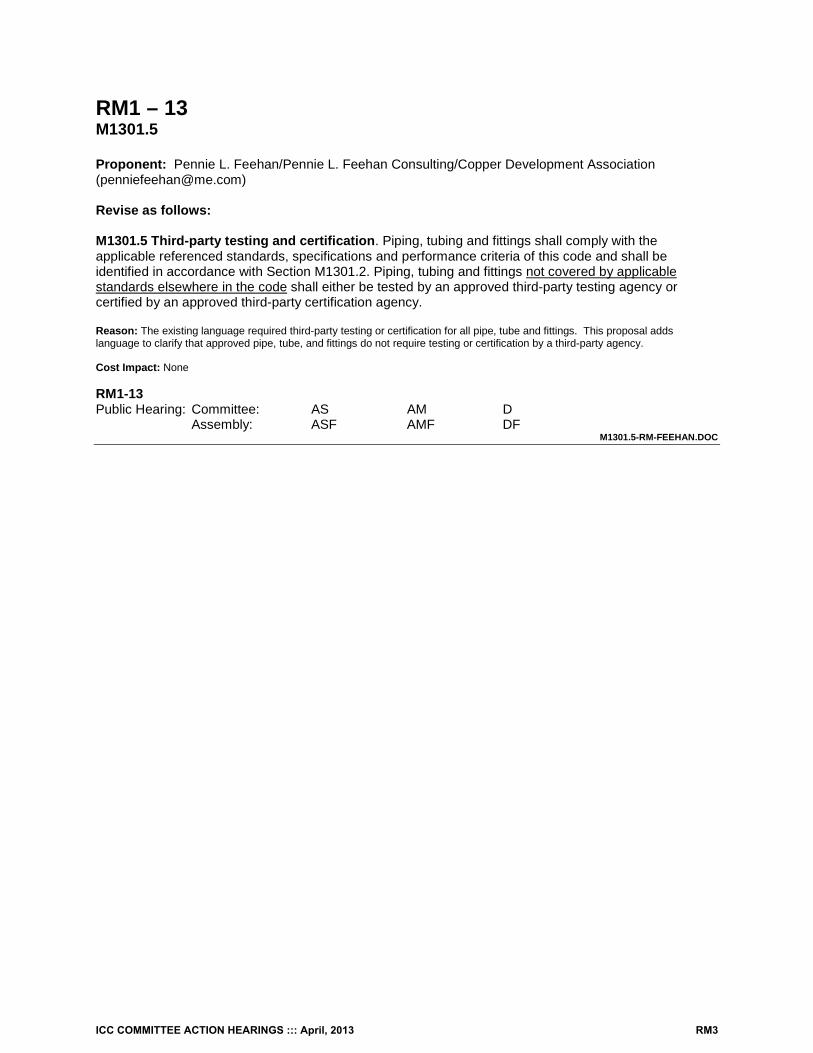
RM1 – 13 M1301.5 Proponent: Pennie L. Feehan/Pennie L. Feehan Consulting/Copper Development Association ([email protected]) Revise as follows: M1301.5 Third-party testing and certification. Piping, tubing and fittings shall comply with the applicable referenced standards, specifications and performance criteria of this code and shall be identified in accordance with Section M1301.2. Piping, tubing and fittings not covered by applicable standards elsewhere in the code shall either be tested by an approved third-party testing agency or certified by an approved third-party certification agency. Reason: The existing language required third-party testing or certification for all pipe, tube and fittings. This proposal adds language to clarify that approved pipe, tube, and fittings do not require testing or certification by a third-party agency. Cost Impact: None RM1-13 Public Hearing: Committee: AS AM D Assembly: ASF AMF DF
M1301.5-RM-FEEHAN.DOC
ICC COMMITTEE ACTION HEARINGS ::: April, 2013 RM3
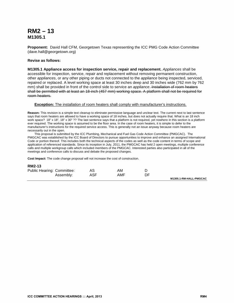
RM2 – 13 M1305.1 Proponent: David Hall CFM, Georgetown Texas representing the ICC PMG Code Action Committee ([email protected]) Revise as follows: M1305.1 Appliance access for inspection service, repair and replacement. Appliances shall be accessible for inspection, service, repair and replacement without removing permanent construction, other appliances, or any other piping or ducts not connected to the appliance being inspected, serviced, repaired or replaced. A level working space at least 30 inches deep and 30 inches wide (762 mm by 762 mm) shall be provided in front of the control side to service an appliance. Installation of room heaters shall be permitted with at least an 18-inch (457 mm) working space. A platform shall not be required for room heaters.
Exception: The installation of room heaters shall comply with manufacturer’s instructions. Reason: This revision is a simple text cleanup to eliminate permissive language and unclear text. The current next to last sentence says that room heaters are allowed to have a working space of 18 inches, but does not actually require that. What is an 18 inch work space? 18” x 18”, 18” x 30” ?? The last sentence says that a platform is not required, yet nowhere in this section is a platform ever required. The working space is assumed to be the floor area. In the case of room heaters, it is simple to defer to the manufacturer’s instructions for the required service access. This is generally not an issue anyway because room heaters are necessarily out in the open.
This proposal is submitted by the ICC Plumbing, Mechanical and Fuel Gas Code Action Committee (PMGCAC). The PMGCAC was established by the ICC Board of Directors to pursue opportunities to improve and enhance an assigned International Code or portion thereof. This includes both the technical aspects of the codes as well as the code content in terms of scope and application of referenced standards. Since its inception in July, 2011, the PMGCAC has held 2 open meetings, multiple conference calls and multiple workgroup calls which included members of the PMGCAC. Interested parties also participated in all of the meetings and conference calls to discuss and debate the proposed changes. Cost Impact: The code change proposal will not increase the cost of construction. RM2-13 Public Hearing: Committee: AS AM D Assembly: ASF AMF DF
M1305.1-RM-HALL-PMGCAC
ICC COMMITTEE ACTION HEARINGS ::: April, 2013 RM4
RM3 – 13 M1305.1.3.1 Proponent: David Hall CFM, Georgetown Texas representing the ICC PMG Code Action Committee ([email protected]) Revise as follows: M1305.1.3.1 Electrical requirements. A luminaire controlled by a switch located at the required passageway opening and a receptacle outlet shall be installed at or near the appliance location in accordance with Chapter 39. Exposed lamps shall be protected from damage by location or lamp guards. Reason: The typical lamp holder (fixture) used for attics and crawl spaces is a porcelain lamp holder with a naked incandescent lamp in it. It is often placed such that service personnel can impact it with their body, tools or materials. The result is broken glass, falling hot metal lamp filaments, possible lacerations, a shock hazard and sudden darkness to top it all off. The use of simple lamp cages/guards or locating the lamp holders out of harm’s way will protect service personnel, which is the intent of this entire code section.
This proposal is submitted by the ICC Plumbing, Mechanical and Fuel Gas Code Action Committee (PMGCAC). The PMGCAC was established by the ICC Board of Directors to pursue opportunities to improve and enhance an assigned International Code or portion thereof. This includes both the technical aspects of the codes as well as the code content in terms of scope and application of referenced standards. Since its inception in July, 2011, the PMGCAC has held 2 open meetings, multiple conference calls and multiple workgroup calls which included members of the PMGCAC. Interested parties also participated in all of the meetings and conference calls to discuss and debate the proposed changes. Cost Impact: The code change proposal will not increase the cost of construction. RM3-13 Public Hearing: Committee: AS AM D Assembly: ASF AMF DF
M1305.1.3.1-RM-HALL-PMGCAC
ICC COMMITTEE ACTION HEARINGS ::: April, 2013 RM5
RM4 – 13 M1305.1.4.3 Proponent: David Hall CFM, Georgetown Texas representing the ICC PMG Code Action Committee ([email protected]) Revise as follows: M1305.1.4.3 Electrical requirements. A luminaire controlled by a switch located at the required passageway opening and a receptacle outlet shall be installed at or near the appliance location in accordance with Chapter 39. Exposed lamps shall be protected from damage by location or lamp guards. Reason: The typical lamp holder (fixture) used for attics and crawl spaces is a porcelain lamp holder with a naked incandescent lamp in it. It is often placed such that service personnel can impact it with their body, tools or materials. The result is broken glass, falling hot metal lamp filaments, possible lacerations, a shock hazard and sudden darkness to top it all off. The use of simple lamp cages/guards or locating the lamp holders out of harm’s way will protect service personnel, which is the intent of this entire code section.
This proposal is submitted by the ICC Plumbing, Mechanical and Fuel Gas Code Action Committee (PMGCAC). The PMGCAC was established by the ICC Board of Directors to pursue opportunities to improve and enhance an assigned International Code or portion thereof. This includes both the technical aspects of the codes as well as the code content in terms of scope and application of referenced standards. Since its inception in July, 2011, the PMGCAC has held 2 open meetings, multiple conference calls and multiple workgroup calls which included members of the PMGCAC. Interested parties also participated in all of the meetings and conference calls to discuss and debate the proposed changes. Cost Impact: The code change proposal will not increase the cost of construction. RM4-13 Public Hearing: Committee: AS AM D Assembly: ASF AMF DF
M1305.1.4.3-RM-HALL-PMGCAC
ICC COMMITTEE ACTION HEARINGS ::: April, 2013 RM6
RM5 – 13 M1306.2, M1306.2.1, M1306.2.2 Proponent: Bob Eugene, representing UL LLC ([email protected]) Revise as follows: M1306.2 Clearance reduction. The reduction of required clearances to combustible assemblies or combustible materials shall be based on Section M1306.2.1 or Section M1306.2.2. M1306.2.1 Labeled assemblies. The allowable clearance shall be based on an approved reduced clearance protective assembly that is listed and labeled in accordance with UL 1618. M1306.2.2 Reduction table. M1306.2 Clearance Reduction. Reduction of clearances shall be in accordance with the appliance manufacturer’s instructions and Table M1306.2. Forms of protection with ventilated air space shall conform to the following requirements:
1. Not less than 1-inch (25 mm) air space shall be provided between the protection and combustible wall surface.
2. Air circulation shall be provided by having edges of the wall protection open at least 1 inch (25 mm).
3. If the wall protection is mounted on a single flat wall away from corners, air circulation shall be provided by having the bottom and top edges, or the side and top edges open at least 1 inch (25 mm).
4. Wall protection covering two walls in a corner shall be open at the bottom and top edges at least 1 inch (25 mm).
Reason: This provides an additional means of reduced clearances consistent with IMC 308.5. Cost Impact: None RM5-13 Public Hearing: Committee: AS AM D Assembly: ASF AMF DF
M1306.2-RM-EUGENE.DOC
ICC COMMITTEE ACTION HEARINGS ::: April, 2013 RM7
RM6 – 13 M1307.2, P2801.7 Proponent: Stephen Kerr, S.E., representing Josephson Werdowatz and Associates, Inc. Revise as follows: M1307.2 Anchorage of appliances. Appliances designed to be fixed in position shall be fastened or anchored in an approved manner. In Seismic Design Categories D0, D1 and D2, and in townhouses in Seismic Design Category C, water heaters shall be anchored or strapped to resist horizontal displacement caused by earthquake motion in accordance with one of the following:
1. Anchorage and strapping shall be designed to resist a horizontal force equal to one-third of the
operating weight of the water heater storage tank, acting in any horizontal direction. Strapping shall be at points within the upper one-third and lover one-third of the appliance’s vertical dimensions. At the lower point, the strapping shall maintain a minimum distance of 4 inches (102mm) above the controls.
2. The anchorage strapping shall be in accordance with the appliance manufacturer’s recommendations.
Revise as follows: P2801.7 Water heater seismic bracing. In Seismic Design Categories D0, D1 and D2 and in townhouses in Seismic Design Category C, water heaters shall be anchored or strapped in accordance with Section M1307.2.the upper one-third and in the lower one third of the appliance to resist a horizontal force equal to one-third of the operating weight of the water heater storage tank, acting in any horizontal direction, or in accordance with the appliance manufacturer’s recommendations. Reason: In the 2006 IRC water heater bracing was added to section P2801.7; however, section M1307.2 already addressed the anchorage of water heaters. The intent of this proposal is to condense the seismic bracing requirements to one location. The seismic requirements from both sections were combined and placed in section M1307.2 with a cross reference from P2801.7. Cost Impact: The proposal will not increase the cost of construction. RM6-13 Public Hearing: Committee: AS AM D Assembly: ASF AMF DF
M1307.2 #1-RM-KERR.DOC
ICC COMMITTEE ACTION HEARINGS ::: April, 2013 RM8
RM7 – 13 M1307.2, M2301.2, M2301.2.10 (New) Proponent: Stephen Kerr, S.E., Josephson Werdowatz and Associates, Inc., representing self Revise as follows: M1307.2 Anchorage of appliances. Appliances designed to be fixed in position shall be fastened or anchored in an approved manner. In Seismic Design Categories D1 and D2, water heaters and thermal storage units shall be anchored or strapped to resist horizontal displacement caused by earthquake motion. Strapping shall be at points within the upper one-third and lower one-third of the appliance’s vertical dimensions. At the lower point, the strapping shall maintain a minimum distance of 4 inches (102mm) above the controls. M2301.2 Installation. Installation of thermal solar energy systems shall comply with Sections M2301.2.1 through M2301.2.910. M2301.2.10 Thermal storage unit seismic bracing. In Seismic Design Categories D0, D1 and D2 and in townhouses in Seismic Design Category C, thermal storage units shall be anchored in accordance with Section M1307.2. Reason: Thermal storage tanks are similar in size and shape to water heaters, with typical residential tank sizes between 50 and 120 gallons. During past earthquakes, water storage tanks (water heaters and thermal storage tanks) have moved or tipped over if they were not securely anchored to adjacent walls or floors. This movement has resulted in water line leaks which can cause significant and costly property damage. The seismic bracing requirements for water heaters should be extended to these appliances. Cost Impact: The cost of construction will slightly increase for the installation of thermal storage tanks. RM7-13 Public Hearing: Committee: AS AM D Assembly: ASF AMF DF
M1307.2 #2-RM-KERR.DOC
ICC COMMITTEE ACTION HEARINGS ::: April, 2013 RM9
RM8 – 13 M1308.1, M1308.2.1 (New), M1308.2.2 (New), M1308.2.3 (New) Proponent: David Hall CFM, Georgetown Texas representing the ICC PMG Code Action Committee ([email protected]) Revise as follows: M1308.1 Protection against physical damage. In concealed locations where piping, other than cast iron or galvanized steel, is installed through holes or notches in studs, joists, rafters or similar members less than 1-1/2 inches (38 mm) from the nearest edge of the member, the pipe shall be protected by steel shield plates. Such shield plates shall have a thickness of not less than 0.0575 inch (1.463 mm) (No. 16 gage). Such plates shall cover the area of the pipe where the member is notched or bored and shall extend not less than 2 inches (51 mm) above sole plates and below top plates. Where piping will be concealed within light-frame construction assemblies, the piping shall be protected against penetration by fasteners in accordance with Sections M1308.2.1 through M1308.2.3.
Exception: Cast iron piping and galvanized steel piping shall not be required to be protected. Add new text as follows: M1308.2.1 Piping through bored holes or notches. Where piping is installed through holes or notches in framing members and the piping is located less than 1 ½ inches (38 mm) from the framing member face to which wall, ceiling or floor membranes will be attached, the pipe shall be protected by shield plates that cover the width of the pipe and the framing member and that extend 2 inches (51 mm) to each side of the framing member. Where the framing member that the piping passes through is a bottom plate, bottom track, top plate or top track, the shield plates shall cover the framing member and extend 2 inches (51 mm) above the bottom framing member and 2 inches (51 mm) below the top framing member. M1308.2.2 Piping in other locations. Where the piping is located within a framing member and is less than 1 ½ inches (38 mm) from the framing member face to which wall, ceiling or floor membranes will be attached, the piping shall be protected by shield plates that cover the width and length of the piping. Where the piping is located outside of a framing member and is located less than 1 ½ inches (38 mm) from the nearest edge of the face of the framing member to which the membrane will be attached, the piping shall be protected by shield plates that cover the width and length of the piping. M1308.2.3 Shield plates. Shield plates shall be of steel material having a thickness of not less than 0.0575 inch (1.463 mm) (No. 16 gage). Reason: This proposal was approved for the 2015 IFGC. This proposal provides clear requirements for where shield plates are needed. Section M1308.1 uses the term “light frame construction assemblies” to describe wall, floor and roof assembles that can be made up from either wood members or light frame, cold formed steel members.
Section M1308.2.1 covers applications where piping runs perpendicular to a framing member and passes through a bored hole or notch in the framing member. This text is nearly the same as what is currently in the IRC. If the piping is within 1 ½ inches of the face of the member where wall, ceiling or floor membranes will be attached, then the piping is required to be protected by a shield plate that covers the width of the piping by the width of the framing member plus 2 inches on either side of the framing member. Protection of the piping on either side of the framing member is needed because it is too easy for a membrane/fastener installer to miss the framing member’s fastening face or penetrate the member at an angle and hit the piping that is just outside of the framing member. Section M1308.2.1 also covers the application where piping runs perpendicular to and penetrates top and bottom plates, or top and bottom tracks. Protection of the piping above the bottom framing member (or below the top framing member) is needed because it is too easy for a membrane/fastener installer to miss the framing member’s fastening face or penetrate the member at an angle and hit the piping just outside of the framing member. The code fails to address the situation where piping is run within the C-channel of a metal stud or joist and it also fails to address piping run parallel to a framing member.
Section M1308.2.2 covers applications where the piping runs alongside of a framing member or in the case of a light frame, cold formed steel framing member, piping that runs parallel to the length of and within the framing member (in other words, within the channel section). If the piping is within 1 ½ inches of the face of the member where wall, ceiling or floor membranes will be attached, then the piping is required to be protected by a shield pate that covers the width of the piping by the length of piping that is within the 1 ½ inch proximity of the framing member’s fastening face. Piping that is located behind the fastening face of the member and within 1 ½ inches of the fastening face of the member obviously needs protection from fastener penetration. Piping that is
ICC COMMITTEE ACTION HEARINGS ::: April, 2013 RM10
located adjacent to and within 1 ½ inches of the fastening face of the member needs protection because it is too easy for a membrane/fastener installer to miss the framing member’s fastening face or penetrate the member at an angle and hit the piping that is just outside of the framing member. A similar requirement in Section E3802.1 applies to wiring run parallel to framing members.
The opposition to this proposal for the IPC was related to the requirement to protect the length of piping that is run parallel to a framing member and less than 1 ½ inches from the member face to which wall board will be screwed or nailed. The concern was expressed that it would be difficult to protect the pipe for its full length, making the assumption that the pipe ran from the bottom plate up through the top plate in walls. First of all, it is unlikely that an installer would install piping from plate to plate that close to the stud, since it would be nearly impossible to drill holes that close to the stud. Secondly, the obvious way to avoid installing protection for the pipe is to simply keep it at least 1 ½ inches away from the framing member. With a little planning, the installation of pipe protection could be easily avoided.
The PMGCAC was established by the ICC Board of Directors to pursue opportunities to improve and enhance an assigned International Code or portion thereof. This includes both the technical aspects of the codes as well as the code content in terms of scope and application of referenced standards. Since its inception in July, 2011, the PMGCAC has held 2 open meetings, multiple conference calls and multiple workgroup calls which included members of the PMGCAC. Interested parties also participated in all of the meetings and conference calls to discuss and debate the proposed changes. Cost Impact: The code change proposal will increase the cost of construction. RM8-13 Public Hearing: Committee: AS AM D Assembly: ASF AMF DF
M1308.1-RM-HALL-PMGCAC
ICC COMMITTEE ACTION HEARINGS ::: April, 2013 RM11
RM9 – 13 M1401.3 Proponent: Richard Grace, Fairfax County VA, representing The Virginia Plumbing and Mechanical Inspectors Association and the Virginia Building and Code Officials Association Revise as follows: M1401.3 Equipment/appliance Sizing. Heating and cooling equipment and appliances shall be sized in accordance with ACCA Manual S based on building loads calculated in accordance with ACCA Manual J or other approved heating and cooling calculation methodologies.
Exception: Heating and cooling equipment and appliances shall not be limited to the capacities determined in accordance with Manual S where any of the following conditions apply:
1. The specified equipment or appliance utilizes multi-stage technology or variable refrigerant flow technology and the loads calculated in accordance with Manual J fall within the range of the manufacturer’s published capacities for that equipment or appliance.
2. The specified equipment or appliance manufacturer’s published capacities cannot satisfy both the total and sensible heat gains calculated in accordance with Manual J and the manufacturer’s next larger standard size unit is specified.
3. The specified equipment or appliance is the lowest capacity unit available from the specified manufacturer.
Reason: Item 1 - Current technology is widely available that incorporates multi-stage or VRF systems for increased efficiency. Some of these appliances have such a wide span of functionality that they extend beyond the allowable requirements outlined in Manual S. However, this technology allows the appliance to operate between minimum and maximum capacities, based on loads imposed, thus eliminating the problems associated with single-stage, oversized appliances. Additionally, the appliance will operate efficiently during times where outdoor air temperatures exceed those used to calculate the loads in Manual J.
Item 2 - Often times, the appliance manufacturer’s published total and sensible capacities are at odds with the requirements of Manual S. There are many cases where the total capacity of the appliance will fall within the parameters of Manual S in relation to the calculated total gain, however the sensible capacity of the appliance may fall short of the calculated sensible gain, thus unable to provide efficient sensible cooling for the space. When the manufacturer’s next standard size larger is chosen to meet the sensible gain, the total capacity of the appliance may then exceed the requirements of Manual S. Choosing the larger appliance will enable a more efficient and effective system.
Item 3 - The current code language does not have provisions for sizing appliances for minimal dwelling unit or dwelling addition loads, other than forcing owners and contractors to change appliances to less desirable systems. For example; a 2 story townhouse, in climate zone 4, with 600 square feet per floor wants to utilize a two-zone system, or a separate heat pump system for each floor. A 1.5 ton unit per floor would exceed the requirements of Manual S, however a 1.5 ton unit could be the smallest available appliance made by the desired manufacturer. Current language would require a complete design change, such as utilizing a single appliance to serve the entire dwelling rather than the more desirable two-zone system, or requiring a system that utilizes electric baseboard heating and window-mounted air conditioning units. This is absurd, and an unfair to an owner that desires to reduce energy costs. Cost Impact: none RM9-13 Public Hearing: Committee: AS AM D Assembly: ASF AMF DF
M1401.3-RM-GRACE.DOC
ICC COMMITTEE ACTION HEARINGS ::: April, 2013 RM12
RM10 – 13 M1401.4 Proponent: Jay F. Rowland, J.F.R. Enterprises, Inc., representing self ([email protected]) Revise as follows: M1401.4 Exterior installations. Equipment installed outdoors shall be listed and labeled for outdoor installation. Supports and foundations shall prevent excessive vibration, settlement or movement of the equipment. Supports and foundations shall be remain level and conform to the manufacturer's installation instructions. Prefabricated supports placed on grade without excavation shall maintain ground contact around the support perimeter and resist erosion and settling. Soil shall be backfilled and secured to a depth of not less than 6 inches (152mm) under the support. Reason: “Other approved materials” (plastic and lightweight concrete pads) have seen continuous reduction of material/ribbing over the years as manufacturers lower costs and compete for market share. Plus, they want to make a lighter product that is friendly to installers. This suggested code change reminds manufacturers and installers that the equipment pads are expected to remain level over time, not just initial installation. Don’t “set it and forget it” unless it’s set correctly.
Take a look at homes in your neighborhood, and you will see that a large percentage of prefab equipment pads have been installed and maintained improperly. Too many pads have lost all soil under their downslope edges and are held in place largely by the weight of the unit and the line set. On the other hand, many pads have no clearance from grade.
Unfortunately, neither manufacturers nor techs have put enough focus on proper excavation of the soil, backfilling, placing rock around the pad, or other steps to resist erosion and settling (which will still occur to some degree even with a perfect install). We stop short of requiring strip footers tied into the pad from below. That’s the best way to stop erosion, but it adds a higher cost, and the manufacturers can come up with similar options.
Installation instructions have been insufficient to address these common issues. In fact, prefab pads as currently made (3” height, and many of 2” height) cannot meet code if the site is properly excavated. Excavation requires going below grade, and a 3” pad cannot then extend 3” above grade. With 3” pads, the best option is to provide protection for the soil under and around the pad. Some calculations by a registered engineer are attached as substantiation of the significance of erosion.
In a nutshell, ground contact/support and erosion control (protecting soil under and around the pad) determine the actual clearance from grade. Cost Impact: The code change proposal will not increase the cost of construction. As phrased, adding rock is an option. Rock would add a little material and labor cost, but also additional revenue. If you expressly require strip footing or a similar solution, then the cost of construction will increase. RM10-13 Public Hearing: Committee: AS AM D Assembly: ASF AMF DF
M1404-RM-ROWLAND.DOC
ICC COMMITTEE ACTION HEARINGS ::: April, 2013 RM13
RM11 – 13 M1403.1, M1601.1, Chapter 44 Proponent: David Hall CFM, Georgetown Texas representing the ICC PMG Code Action Committee ([email protected]) Revise as follows: M1403.1 Heat pumps. The minimum unobstructed total area of the outdoor and return air ducts or openings to a heat pump shall be not less than 6 square inches per 1,000 Btu/h (13 208 mm2/kW) output rating or as indicated by the conditions of listing of the heat pump. Electric heat pumps shall be conform to listed and labeled in accordance with UL 1995 or UL/CSA/ANCE 60335-2-40. M1601.1 Duct design. Duct systems serving heating, cooling and ventilation equipment shall be installed in accordance with the provisions of this section and ACCA Manual D, the appliance manufacturer’s installation instructions or other approved methods. Add new standard to Chapter 44 as follows: UL/CSA/ANCE 60335-2-40-2012 Household and Similar Electrical Appliances, Part 2-40: Particular
Requirements for Electrical Heat Pumps, Air-Conditioners and Dehumidifiers……..R1403.1.
Reason: With the exception of adding UL/CSA/ANCE 60335-2-40, this revised language was approved for the 2015 IMC. This is outdated legacy code language and is not consistent with current practice. It is up to the design professional, or the requirements from Manual D or the manufacturer of the appliances to determine minimum sizes of ducts and transfer openings, not the code. If these numbers where to be applied, then the code could be condoning an undersized system. There are too many variables and different situations for just one minimum to work for everything.
UL/CSA/ANCE 60335-2-40 Household and Similar Electrical Appliances, Part 2-40: Particular Requirements for Electrical Heat Pumps, Air-Conditioners and Dehumidifiers is a new harmonized standard which is an alternate to UL 1995. Cost Impact: None listed. Analysis: A review of the standard proposed for inclusion in the code, [UL/CSA/ANCE 60335-2-40-2012] with regard to the ICC criteria for referenced standards (Section 3.6 of CP#28) will be posted on the ICC website on or before April 1, 2013. RM11-13 Public Hearing: Committee: AS AM D Assembly: ASF AMF DF
M1403.1 #1-RM-HALL-PMGCAC
ICC COMMITTEE ACTION HEARINGS ::: April, 2013 RM14
RM12 – 13 M1403.1, M1601.1 Proponent: David Hall CFM, Georgetown Texas representing the ICC PMG Code Action Committee ([email protected]) Revise as follows: M1403.1 Heat pumps. The minimum unobstructed total area of the outdoor and return air ducts or openings to a heat pump shall be not less than 6 square inches per 1,000 Btu/h (13 208 mm2/kW) output rating or as indicated by the conditions of listing of the heat pump. Electric heat pumps shall be tested in accordance with UL 1995. M1601.1 Duct design. Duct systems serving heating, cooling and ventilation equipment shall be installed in accordance with the provisions of this section and ACCA Manual D, the appliance manufacturer’s installation instructions or other approved methods. Reason: This language deletion was approved for the 2015 IMC. This is outdated legacy code language and is not consistent with current practice. It is up to the design professional, or the requirements from Manual D or the manufacturer of the appliances to determine minimum sizes of ducts and transfer openings, not the code. If these numbers where to be applied, then the code could be condoning an undersized system. There are too many variables and different situations for just one minimum to work for everything. Cost Impact: None RM12-13 Public Hearing: Committee: AS AM D Assembly: ASF AMF DF
M1403.1 #2-RM-HALL-PMGCAC
ICC COMMITTEE ACTION HEARINGS ::: April, 2013 RM15
RM13 – 13 M1403.1, Chapter 44 Proponent: Bob Eugene, representing UL LLC. ([email protected]) Revise as follows: M1403.1 Heat pumps. The minimum unobstructed total area of the outside and return air ducts or openings to a heat pump shall be not less than 6 square inches per 1,000 Btu/h (13 208 mm2/kW) output rating or as indicated by the conditions of the listing of the heat pump. Electric heat pumps shall conform to UL 1995 or UL/CSA/ANCE 60335-2-40. Add new standard to Chapter 44 as follows: UL/CSA/ANCE 60335-2-40--2012 Reason: Through AHRI, manufactures requested that UL publish a harmonized IEC based 60335-2-40, to replace UL 1995 for equipment within the scope of 60335-2-40 rated 600 volts and less. UL60335-2-40 will be effective upon publication, however UL 1995 will not sunset for new equipment until November 2020 and existing equipment by 2022. UL/CSA/ANCE 60335-2-40 is a new tri-national standard that provides a comprehensive set of construction and performance requirements that are used to evaluate and list heat pumps. Cost Impact: None Analysis: A review of the standard proposed for inclusion in the code, [UL/CSA/ANCE 60335-2-40-2012] with regard to the ICC criteria for referenced standards (Section 3.6 of CP#28) will be posted on the ICC website on or before April 1, 2013. RM13-13 Public Hearing: Committee: AS AM D Assembly: ASF AMF DF
M1403.1-RM-EUGENE.DOC
ICC COMMITTEE ACTION HEARINGS ::: April, 2013 RM16
RM14 – 13 M1403.2 Proponent: Guy McMann, MCP, Jefferson County Colorado, representing Colorado Association of Plumbing and Mechanical Officials (CAPMO) ([email protected]) Delete as follows: M1403.2 Foundations and supports. Supports and foundations for the outdoor unit of a heat pump shall be raised at least 3 inches (76 mm) above the ground to permit free drainage of defrost water, and shall conform to the manufacturer's installation instructions. Reason: This subject is already covered in M-1305.1.4.1 and covers all appliances. There is no need to duplicate it here. Cost Impact: None RM14-13 Public Hearing: Committee: AS AM D Assembly: ASF AMF DF
M1403.2-RM-MCMANN.DOC
ICC COMMITTEE ACTION HEARINGS ::: April, 2013 RM17
RM15 – 13 M1410.1 Proponent: Bob Eugene, representing UL LLC ([email protected]) Revise as follows: M1410.1 General. Vented room heaters shall be tested in accordance with ASTM E 1509 for pellet-fuel burning, UL 896 for oil-fired or UL 1482 for solid fuel-fired and installed in accordance with their listing, the manufacturer’s installation instructions and the requirements of this code. Reason: Clarify application of ASTM E 1509. Cost Impact: None RM15-13 Public Hearing: Committee: AS AM D Assembly: ASF AMF DF
M1410.1-RM-EUGENE.DOC
ICC COMMITTEE ACTION HEARINGS ::: April, 2013 RM18
RM16 – 13 M1410.2 Proponent: Bob Eugene, UL LLC ([email protected]) Revise as follows: M1410.2 Floor mounting. Room heaters shall be installed on noncombustible floors or approved assemblies constructed of noncombustible materials that extend at least 18 inches (457 mm) beyond the appliance on all sides.
Exceptions:
1. Listed room heaters shall be installed on noncombustible floors, assemblies constructed of noncombustible materials or listed floor protectors listed and labeled in accordance with UL 1618. The with materials and dimensions shall be in accordance with the appliance manufacturer’s instructions.
2. Room heaters listed for installation on combustible floors without floor protection shall be installed in accordance with the appliance manufacturer’s instructions.
Reason: Add the referenced standard for listing of floor protectors. Cost Impact: None RM16-13 Public Hearing: Committee: AS AM D Assembly: ASF AMF DF
M1410.2-RM-EUGENE
ICC COMMITTEE ACTION HEARINGS ::: April, 2013 RM19
RM17 – 13 M1411.3.1 Proponent: Jay F. Rowland, J.F.R. Enterprises, Inc., representing self ([email protected]) Revise as follows: M1411.3.1 Auxiliary and secondary drain systems. In addition to the requirements of Section M1411.3, a secondary drain or auxiliary drain pan shall be required for each cooling or evaporator coil where damage to any building components will occur as a result of overflow from the equipment drain pan or stoppage in the condensate drain piping. Such piping shall maintain a minimum horizontal slope in the direction of discharge of not less than 1/8 unit vertical in 12 units horizontal (1-percent slope). Drain piping shall be a minimum of 3/4-inch (19 mm) nominal pipe size. One of the following methods shall be used:
1. An auxiliary drain pan with a separate drain shall be provided under the coils on which condensation will occur. The auxiliary pan drain shall discharge to a conspicuous point of disposal to alert occupants in the event of a stoppage of the primary drain. The pan shall have a minimum depth of 1.5 inches (38 mm), shall not be less than 3 inches (76 mm) larger than the unit or the coil dimensions in width and length and shall be constructed of corrosion-resistant material. Galvanized sheet steel pans shall have a minimum thickness of not less than 0.0236 inch (0.6010 mm) (No. 24 gage). Nonmetallic pans shall have a minimum thickness of not less than 0.0625 inch (1.6 mm). The auxiliary drain pan shall be equipped with a water-level detection device conforming to UL 508 that will shut off the equipment served prior to overflow of the pan.
2. A separate overflow drain line shall be connected to the primary drain pan provided with the
equipment. Such overflow drain shall discharge to a conspicuous point of disposal to alert occupants in the event of a stoppage of the primary drain. The overflow drain line shall connect to the drain pan at a higher level than the primary drain connection. A water-level detection device conforming to UL 508 shall be provided that will shut off the equipment served in the event that the primary drain is blocked. The device shall be installed in the primary drain line, the overflow drain line, or in the equipment-supplied drain pan, located at a point higher than the primary drain line connection and below the overflow rim of such pan.
3. An auxiliary drain pan without a separate drain line shall be provided under the coils on which condensate will occur. Such pan shall be equipped with a water-level detection device conforming to UL 508 that will shut off the equipment served prior to overflow of the pan. The pan shall be equipped with a fitting to allow for drainage. The auxiliary drain pan shall be constructed in accordance with Item 1 of this section.
4. A water-level detection device conforming to UL 508 shall be provided that will shut off the equipment served in the event that the primary drain is blocked. The device shall be installed in the primary drain line, the overflow drain line, or in the equipment-supplied drain pan, located at a point higher than the primary drain line connection and below the overflow rim of such pan.
Reason: This code change is requested in order to reduce confusion caused by the wording and to bring the code in line with traditional best procedures. The end result is building occupants saved from condensate catastrophes.
For decades, contractors have commonly installed three lines of protection against condensate overflow. Besides the drain line from the primary drain pan, they installed a secondary drain pan with a drain line and a float switch or similar device in the secondary drain pan. This practice is still common today, as evidenced by the strong tandem sales of shut-off devices along with secondary pans with holes pre-drilled.
The code body recognized this best practice with the opening paragraph that requires a secondary drain or auxiliary drain pan. However, the statement that “One of the following methods shall be used…” contradicts the opening statement and provides room for corners to be cut during installation.
ICC COMMITTEE ACTION HEARINGS ::: April, 2013 RM20
The code, as currently interpreted in some jurisdictions, allows the installer to drop one line of protection as a way of saving a little money in the short run. The current requirement is for the drain from the primary pan to be backed up by only one other option. If the secondary drain line clogs, and there is no shut-off device, then the building is damaged. If the shut-off fails, and there is no secondary drain, then the building is damaged. The risk of a secondary device failing is significant, so a tertiary device isn’t overkill. It is wise, and that seemed to be the intent of the code.
The code body should not assume that equipment is properly installed or maintained or, even if it is, that mechanical devices will always perform as desired. Especially over time, as all things perform less effectively as they age.
This code change uses existing language in a different arrangement (making methods 3 & 4 part of methods 1 & 2, respectively).
Note: We added the word “primary” to section 2 because some equipment is provided with both primary and secondary drain pans. Cost Impact: The code change proposal will not increase the cost of construction. At least this is true for the contractors who protect their customers and follow the traditional best practices. Alternatively, we would point out that the cost of keeping the third line of defense against condensate damage is much lower than the cost of re-construction after damage is done. Home insurance usually does not cover this type of flooding. Thank you for your consideration. RM17-13 Public Hearing: Committee: AS AM D Assembly: ASF AMF DF
M1411.3.1-#1-RM-ROWLAND.DOC
ICC COMMITTEE ACTION HEARINGS ::: April, 2013 RM21
RM18 – 13 M1411.3.1 Proponent: Jay F. Rowland, J.F.R. Enterprises, Inc., representing self ([email protected]) Revise as follows: M1411.3.1 Auxiliary and secondary drain systems. In addition to the requirements of Section M1411.3, a secondary drain or auxiliary drain pan shall be required for each cooling or evaporator coil where damage to any building components will occur as a result of overflow from the equipment drain pan or stoppage in the condensate drain piping. Such piping shall maintain a minimum horizontal slope in the direction of discharge of not less than 1/8 unit vertical in 12 units horizontal (1-percent slope). Drain piping shall be a minimum of 3/4-inch (19 mm) nominal pipe size. One of the following methods shall be used:
1. An auxiliary drain pan with a separate drain shall be installed under the coils on which condensation will occur. The auxiliary pan drain shall discharge to a conspicuous point of disposal to alert occupants in the event of a stoppage of the primary drain. The pan shall have a minimum depth of 1.5 inches (38 mm), shall not be less than 3 inches (76 mm) larger than the unit or the coil dimensions in width and length and shall be constructed of corrosion-resistant material. Galvanized sheet steel pans shall have a minimum thickness of not less than 0.0236-inch (0.6010 mm) (No. 24 Gage), shall have seamless corners, and the interior shall be coated with a waterproof material. Nonmetallic pans shall have a minimum thickness of not less than 0.0625 inch (1.6 mm).
2. A separate overflow drain line shall be connected to the drain pan installed with the equipment. This overflow drain shall discharge to a conspicuous point of disposal to alert occupants in the event of a stoppage of the primary drain. The overflow drain line shall connect to the drain pan at a higher level than the primary drain connection.
3. An auxiliary drain pan without a separate drain line shall be installed under the coils on which condensation will occur. This pan shall be equipped with a water level detection device conforming to UL 508 that will shut off the equipment served prior to overflow of the pan. The pan shall be equipped with a fitting to allow for drainage. The auxiliary drain pan shall be constructed in accordance with Item 1 of this section.
4. A water level detection device conforming to UL 508 shall be installed that will shut off the equipment served in the event that the primary drain is blocked. The device shall be installed in the primary drain line, the overflow drain line or the equipment-supplied drain pan, located at a point higher than the primary drain line connection and below the overflow rim of such pan.
Reason: This code change is proposed to address the quality of drain pans, which play an obviously key role in preventing damage due to condensate.
First, we suggest that drain pan corners be “seamless,” such as folded corners for metal pans. Notched corners that are later caulked, or perhaps welded, are prone to error.
More importantly, we suggest that drain pans essentially be rustproof. Resisting rust is not sufficient, because the drain pan is the one thing that should not rust through…and the technologies and products available today provide easy solutions. Polymer coatings, plastic pans, etc. have been used and proven for years. We’ve never seen a plastic pan rust through.
We stop short of saying that the entire pan must be rustproof, and focus only on the interior of the pan, because galvanized steel is so widely used. However, popularity does not justify its continued widespread use for this application. Whenever serious damage is caused to a building due to a rusted or leaky pan, it’s a pretty safe bet that the pan was galvanized steel.
Code officials should not assume that the homeowner will have their equipment (and pan) properly serviced by a professional. In that light, placing a galvanized pan above the homeowner’s ceiling is like placing a time bomb there. Besides the fact that pans rust even with proper and regular maintenance.
We believe this code change will increase the quality of construction and reflect well on the code. Cost Impact: The code change proposal will NOT increase the cost of construction.
For residential installations, plastic pans are readily available in standard sizes. Many areas of the country have already made the switch. For contractors who insist on galvanized pans, they may coat their pans before installation, rather than after they start to rust. This will save them from some pretty ugly customer calls.
ICC COMMITTEE ACTION HEARINGS ::: April, 2013 RM22
Damage from condensate overflow usually is not covered by the homeowner’s property insurance. Therefore, the potential savings to the homeowner is significant. Thank you for your consideration. RM18-13 Public Hearing: Committee: AS AM D Assembly: ASF AMF DF
M1411.3.1-#2-RM-ROWLAND.DOC
ICC COMMITTEE ACTION HEARINGS ::: April, 2013 RM23
RM19 – 13 M1411.3.2 Proponent: Michael Cudahy, Plastic Pipe and Fittings Association, representing Plastic Pipe and Fittings Association ([email protected]) Revise as follows: M1411.3.2 Drain pipe materials and sizes. Components of the condensate disposal system shall be ABS, cast iron, copper, cross-linked polyethylene, CPVC, galvanized steel, copper, polybutylene, PE-RT, polyethylene, ABS, CPVC, polypropylene or PVC, pipe or tubing. All components shall be selected for the pressure and temperature rating of the installation. Joints and connections shall be made in accordance with the applicable provisions of Chapter 30. Condensate waste and drain line size shall not be less than ¾-inch (19 mm) internal diameter and shall not decrease in size from the drain pan connection to the place of condensate disposal. Where the drain pipes from more than one unit are manifolded together for condensate drainage, the pipe or tubing shall be sized in accordance with an approved method. Reason: Delete PB material, as it is no longer available or used in this application, and add raised temperature polyethylene, and polypropylene materials that are available and could be used in this application. Also, alphabetize the list of names. Cost Impact: None RM19-13 Public Hearing: Committee: AS AM D Assembly: ASF AMF DF
M1411.3.2#1-RM-CUDAHY.DOC
ICC COMMITTEE ACTION HEARINGS ::: April, 2013 RM24
RM20 – 13 M1411.3.2 Proponent: Michael Cudahy, Plastic Pipe and Fittings Association, representing Plastic Pipe and Fittings Association ([email protected]) Revise as follows: M1411.3.2 Drain pipe materials and sizes. Components of the condensate disposal system shall be cast iron, galvanized steel, copper, polybutylene, polyethylene, ABS, CPVC or PVC pipe or tubing. All components shall be selected for the pressure and temperature rating of the installation. All components shall be selected for the pressure and temperature rating of the installation. Joints and connections shall be made in accordance with the applicable provisions of Chapter 30. Condensate waste and drain line size shall be not less than ¾-inch (19 mm) nominal internal diameter and shall not decrease in size from the drain pan connection to the place of condensate disposal. Where the drain pipes from more than one unit are manifolded together for condensate drainage, the pipe or tubing shall be sized in accordance with an approved method. Reason: This second proposal on this section would attempt to clarify that the pipe used is ¾” as a minimum, which seems to already be the field practice, and not ¾” ID pipe. There appeared to be some confusion on the application of the language in the field. Cost Impact: None RM20-13 Public Hearing: Committee: AS AM D Assembly: ASF AMF DF
M1411.3.2 #2-RM-CUDAHY.DOC
ICC COMMITTEE ACTION HEARINGS ::: April, 2013 RM25
RM21 – 13 M1411.3.3 (New) Proponents: David Hall CFM, Georgetown Texas representing the ICC PMG Code Action Committee ([email protected]); Andrew Scott Jones, President, A Better Deal Heating and Air Conditioning, Inc., a Texas Corporation, representing himself. Add new text as follows: M1411.3.3 Drain Line Maintenance. Condensate drain lines shall be configured to permit the clearing of blockages and performance of maintenance without requiring the drain line to be cut. Reason: (Hall-PMGCAC): This new language was approved for the 2015 IMC. Drain line stoppages in evaporative coils drain pan drain lines are unavoidable and common occurrences requiring clearing the drain line. Clearing these lines almost always involves cutting the drain line itself, causing water to leak into the attic, crawlspace, closet, etc. The cut must be repaired by reconnecting the drain line with a PVC coupling and solvent cement.
This process exposes the surrounding area to water leakage and spilling with the risk of damage and mold, as well as the extra time and effort of carrying extra equipment, parts and flammable solvent. The repair process takes extra time and costs the homeowner more money. (Jones): This language is identical to the language of M32-12 which was recently adopted in Portland, Oregon. We are advised by JB Engineering that this language will be in the IMC and IPC for 2015. There appears to be no reason not to accept this identical language in the IRC. Drain line stoppages in evaporative coils drain pan drain lines are unavoidable and common occurrences requiring clearing the drain line. Clearing these lines almost always involves cutting the drain line itself, causing water to leak into the attic or closet where the drain is located, possibly collected in a bucket or soaked up with rags or paper towels. Then the technician blows compressed air through the drain line in both directions from the cut. The cut must be repaired by resealing the drain line with a PVC coupling and solvent.
This process exposes the surrounding area to water leakage and spilling with the risk of damage, mold, spilling, as well as the extra time and effort of carrying extra equipment, parts and flammable solvent. The process takes extra time and costs the homeowner more money.
With a device that permits the introduction of compressed air or nitrogen directly into the drain system permitting clearing in both directions, there is no spillage of water, no cost for the couplings or solvent and no risk of water damage or mold. The entire process requires less than ten minutes.
Typically the cost of clearing a drain equipped with such a device is at least 50% less to the homeowner than the cost of clearing a blockage through the common method of cutting the pipe, attempting to collect the condensate water and repairing the cut in the drain line.
Each time a drain line is cleared though the cutting/repair process, the repair could be accomplished by installing a $15.00 line clearing device rather than a simple coupling. Drain lines can also be plumbed without installing a device at the time of installation.
Also, if clearing the drain lines were part of regular maintenance, line blockages could largely be prevented in the first place. Cost Impact: (Hall-PMGCAC): The code change will increase the cost of construction. (Jones): The code change will increase the cost of construction, totaling an estimated $15.00 per unit. RM21-13 Public Hearing: Committee: AS AM D Assembly: ASF AMF DF
M1411.3.3 (NEW)-RM-HALL-PMGCAC-JONES.DOC
ICC COMMITTEE ACTION HEARINGS ::: April, 2013 RM26
RM22 – 13 M1411.4 (New) Proponent: David Hall CFM, Georgetown Texas representing the ICC PMG Code Action Committee ([email protected]); Guy McMann, Jefferson County Co., representing Colorado Association of Plumbing and Mechanical Officials (CAPMO) ([email protected]) Add new text as follows: M1411.4 Condensate pumps. Condensate pumps located in uninhabitable spaces, such as attics and crawl spaces, shall be connected to the appliance or equipment served such that when the pump fails, the appliance or equipment will be prevented from operating. Pumps shall be installed in accordance with the manufacturer’s instructions. Reason: (Hall-PMGCAC): Most condensate pumps are factory equipped with float switch controls for this purpose. This new text simply requires the switch to be utilized. Spaces such as attics and crawls are out of sight and out of mind, therefore condensate overflow will not be noticed until damage occurs. The overflow kill switch will shut off the equipment that produces the condensate before water damage can occur. (McMann): This was approved in the Fuel Gas Code and the IMC. Pumps that are not connected in this fashion will permit the appliances to keep operating, spilling waste water where ever the appliance is located. When this condition continues over time, it could result in damage to building components or other property. This overflow condition may result in mold issues among other things. Most pump manufacturers already have this feature incorporated into the pump but the code does not require it to be connected. Damage as a result of not connecting this feature could prove to be very costly. This is not as much of a concern when appliances are readily accessible to occupants where leakage may be noticed in a timely manner. Cost Impact: None RM22-13 Public Hearing: Committee: AS AM D Assembly: ASF AMF DF
M1411.4 (NEW)-RM-HALL-PMGCAC-MCMANN.DOC
ICC COMMITTEE ACTION HEARINGS ::: April, 2013 RM27
RM23 – 13 M1411.6 (New) Proponent: Guy McMann, Jefferson County Colorado, representing Colorado Association of Plumbing and Mechanical Officials (CAPMO) Add text as follows: M1411.6 Location and protection of refrigerant piping. Refrigerant piping installed within 3 inches of the underside of roof decks shall be protected from damage caused by nails and other fasteners. Reason: In many instances piping has been punctured or damaged as a result of being located too close to roof decks, discharging into attics or ceiling spaces and posing health risks. Roofing or re-roofing operations are usually the case for this type of damage. This is very apparent in hail prone locations. Keeping the pipe away from the roof deck will prevent this from occurring reducing repair costs and yet still providing flexibility in the installation. Cost Impact: None RM23-13 Public Hearing: Committee: AS AM D Assembly: ASF AMF DF
M1411.6 (NEW)-RM-MCMANN.DOC
ICC COMMITTEE ACTION HEARINGS ::: April, 2013 RM28
RM24 – 13 1411.6 Proponent: John Arrigo, Brevard Cooling and Heating Inc., representing self Delete as follows: 1411.6 Locking access port caps. Refrigerant circuit access ports located outdoors shall be fitted with locking type tamper resistant caps or shall be otherwise secured to prevent unauthorized access. Reason: Locking caps do not properly lock onto the third port service valve on a heat pump condenser called a "true suction port" It has been our experience and others that the locking cap does not lock fully, posing major issues. Many of these caps can be twisted off by hand, without using the key. These caps appear to be seated, but with a twist off by hand means the gasket is not fully seating! All these caps will leak refrigerant into the air causing a major environmental concern and increased costs to homeowners. If the cap can be twisted off by hand then there is no need for a locking cap! How many caps are like this? The locking key of one brand uses a tire schrader remover to remove the cap. These can be picked up at any local store! Why not consider a brass cap that is locked down with a crescent wrench as a locking cap? With this economic impact it would be cheaper and safer to use the manufactures factory supplied caps that come with the condenser. How can these locking caps be EPA approved? Cost Impact: The code change will not increase cost of construction. RM24-13 Public Hearing: Committee: AS AM D Assembly: ASF AMF DF
M1411.6-RM-ARRIGO.DOC
ICC COMMITTEE ACTION HEARINGS ::: April, 2013 RM29
RM25 – 13 M1412.1, Chapter 44 Proponent: Bob Eugene, representing UL LLC.([email protected]) Revise as follows: M1412.1 Approval of equipment. Absorption systems shall be installed in accordance with the manufacturer’s installation instructions. Absorption equipment shall comply with UL 1995 or UL/CSA/ANCE 60335-2-40. . Add new standard to Chapter 44 as follows: UL/CSA/ANCE 60335-2-40--2012 Reason: Through AHRI, manufactures requested that UL publish a harmonized IEC based 60335-2-40, to replace UL 1995 for equipment within the scope of 60335-2-40 rated 600 volts and less. UL60335-2-40 will be effective upon publication, however UL 1995 will not sunset for new equipment until November 2020 and existing equipment by 2022. UL/CSA/ANCE 60335-2-40 is a new tri-national standard that provides a comprehensive set of construction and performance requirements that are used to evaluate and list absorption systems. Cost Impact: None Analysis: A review of the standard proposed for inclusion in the code, [UL/CSA/ANCE 60335-2-40--2012] with regard to the ICC criteria for referenced standards (Section 3.6 of CP#28) will be posted on the ICC website on or before April 1, 2013. RM25-13 Public Hearing: Committee: AS AM D Assembly: ASF AMF DF
M1412.1-RM-EUGENE.DOC
ICC COMMITTEE ACTION HEARINGS ::: April, 2013 RM30
RM26 – 13 M1413.1, Chapter 44 Proponent: Bob Eugene, representing UL LLC.([email protected]) Revise as follows: M1413.1 General. Evaporative cooling equipment and appliances shall comply with UL 1995 or UL/CSA/ANCE 60335-2-40 and shall be installed:
1. According to the manufacturer’s instructions. 2. On level platforms in accordance with Section M1305.1.4.1. 3. So that openings in exterior walls are flashed in accordance with Section R703.8. 4. So as to protect the potable water supply in accordance with Section P2902. 5. So that air intake opening locations are in accordance with Section R303.5.1.
Add new standard to Chapter 44 as follows: UL/CSA/ANCE 60335-2-40-2012 Reason: Through AHRI, manufactures requested that UL publish a harmonized IEC based 60335-2-40, to replace UL 1995 for equipment within the scope of 60335-2-40 rated 600 volts and less. UL60335-2-40 will be effective upon publication, however UL 1995 will not sunset for new equipment until November 2020 and existing equipment by 2022. UL/CSA/ANCE 60335-2-40 is a new tri-national standard that provides a comprehensive set of construction and performance requirements that are used to evaluate and list evaporative cooling equipment and appliances. Cost Impact: None Analysis: A review of the standard proposed for inclusion in the code, [UL/CSA/ANCE 60335-2-40-2012] with regard to the ICC criteria for referenced standards (Section 3.6 of CP#28) will be posted on the ICC website on or before April 1, 2013. RM26-13 Public Hearing: Committee: AS AM D Assembly: ASF AMF DF
M1413.1-RM-EUGENE.DOC
ICC COMMITTEE ACTION HEARINGS ::: April, 2013 RM31
RM27 – 13 M1501.2 (New) Proponent: Dan Buuck, representing National Association of Home Builders (NAHB) ([email protected]) Add text as follows: M1501.2 Transfer air. Air transferred from occupiable spaces, other than kitchens, bathrooms and toilet rooms, shall not be prohibited from serving as makeup air for exhaust systems. Transfer openings between spaces shall be of the same cross-sectional area as the free area of the makeup air openings. Where louvers and grilles are installed, the required size of openings shall be based on the net free area of each opening. Where the design and free area of louvers and grilles are not known, it shall be assumed that wood louvers have 25-percent free area and metal louvers and grilles have 75-percent free area. Reason: The IMC contains language allowing makeup air to be provided from areas other than the room where the exhaust system is located (transfer air). It is just as important to clarify the allowable use of transfer air for exhaust systems in the IRC as it is in the IMC. Without this provision, Section M1503.4 can be interpreted that the total amount of makeup air is required to be introduced in the direct vicinity of the exhaust. This is not required in commercial construction, and so the IRC should be brought into alignment with the IMC in this area. Most of the language is taken from existing sections of the code. They include: Transfer air: IMC Section 403; Transfer openings: Section M1602 Item 6; and Louvers and grilles: Section G2407.10. Cost Impact: The code change proposal will not increase the cost of construction. RM27-13 Public Hearing: Committee: AS AM D Assembly: ASF AMF DF
M1501.2-RM-BUUCK.DOC
ICC COMMITTEE ACTION HEARINGS ::: April, 2013 RM32
RM28 – 13 M1502.1 through M1502.5 Proponent: Guy McMann, Jefferson County Co., representing Colorado Association of Plumbing and Mechanical Officials (CAPMO) ([email protected]) Revise as follows:
SECTION M1502 CLOTHES DRYER EXHAUST
M1502.1 General. Clothes dryers shall be exhausted in accordance with the manufacturer's instructions and Section G2439. Delete without substitution: M1502.2 Independent exhaust systems. Dryer exhaust systems shall be independent of all other systems and shall convey the moisture to the outdoors.
Exception: This section shall not apply to listed and labeled condensing (ductless) clothes dryers. M1502.3 Duct termination. Exhaust ducts shall terminate on the outside of the building. Exhaust duct terminations shall be in accordance with the dryer manufacturer's installation instructions. If the manufacturer's instructions do not specify a termination location, the exhaust duct shall terminate not less than 3 feet (914 mm) in any direction from openings into buildings. Exhaust duct terminations shall be equipped with a backdraft damper. Screens shall not be installed at the duct termination. M1502.4 Dryer exhaust ducts. Dryer exhaust ducts shall conform to the requirements of Sections M1502.4.1 through M1502.4.6. M1502.4.1 Material and size. Exhaust ducts shall have a smooth interior finish and shall be constructed of metal having a minimum thickness of 0.0157 inches (0.3950 mm) (No. 28 gage) The duct size shall be 4 inches (102 mm) nominal in diameter. M1502.4.2 Duct installation. Exhaust ducts shall be supported at intervals not to exceed 12 feet (3658 mm) and secured in place. The insert end of the duct shall extend into the adjoining duct or fitting in the direction of airflow. Exhaust duct joints shall be sealed in accordance with Section M1601.4.1 and shall be mechanically fastened. Ducts shall not be joined with screws or similar fasteners that protrude more than 1/8 inch (3.2 mm) into the inside of the duct. M1502.4.3 Transition duct. Transition ducts used to connect the dryer to the exhaust duct system shall be a single length that is listed and labeled in accordance with UL 2158A. Transition ducts shall be a maximum of 8 feet (2438 mm) in length. Transition ducts shall not be concealed within construction. M1502.4.4 Duct length. The maximum allowable exhaust duct length shall be determined by one of the methods specified in Section M1502.4.4.1 or M1502.4.4.2. M1502.4.4.1 Specified length. The maximum length of the exhaust duct shall be 35 feet (10668 mm) from the connection to the transition duct from the dryer to the outlet terminal. Where fittings are used, the maximum length of the exhaust duct shall be reduced in accordance with Table M1502.4.4.1. The maximum length of the exhaust does not include the transition duct.
ICC COMMITTEE ACTION HEARINGS ::: April, 2013 RM33
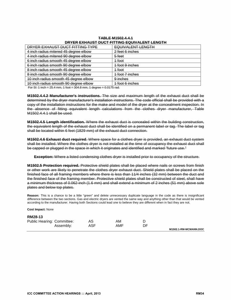
TABLE M1502.4.4.1 DRYER EXHAUST DUCT FITTING EQUIVALENT LENGTH
DRYER EXHAUST DUCT FITTING TYPE EQUIVALENT LENGTH 4 inch radius mitered 45 degree elbow 2 feet 6 inches 4 inch radius mitered 90 degree elbow 5 feet 6 inch radius smooth 45 degree elbow 1 foot 6 inch radius smooth 90 degree elbow 1 foot 9 inches 8 inch radius smooth 45 degree elbow 1 foot 8 inch radius smooth 90 degree elbow 1 foot 7 inches 10 inch radius smooth 45 degree elbow 9 inches 10 inch radius smooth 90 degree elbow 1 foot 6 inches For SI: 1 inch = 25.4 mm, 1 foot = 304.8 mm, 1 degree = 0.0175 rad. M1502.4.4.2 Manufacturer's instructions. The size and maximum length of the exhaust duct shall be determined by the dryer manufacturer's installation instructions. The code official shall be provided with a copy of the installation instructions for the make and model of the dryer at the concealment inspection. In the absence of fitting equivalent length calculations from the clothes dryer manufacturer, Table M1502.4.4.1 shall be used. M1502.4.5 Length identification. Where the exhaust duct is concealed within the building construction, the equivalent length of the exhaust duct shall be identified on a permanent label or tag. The label or tag shall be located within 6 feet (1829 mm) of the exhaust duct connection. M1502.4.6 Exhaust duct required. Where space for a clothes dryer is provided, an exhaust duct system shall be installed. Where the clothes dryer is not installed at the time of occupancy the exhaust duct shall be capped or plugged in the space in which it originates and identified and marked "future use."
Exception: Where a listed condensing clothes dryer is installed prior to occupancy of the structure. M1502.5 Protection required. Protective shield plates shall be placed where nails or screws from finish or other work are likely to penetrate the clothes dryer exhaust duct. Shield plates shall be placed on the finished face of all framing members where there is less than 11/4 inches (32 mm) between the duct and the finished face of the framing member. Protective shield plates shall be constructed of steel, shall have a minimum thickness of 0.062-inch (1.6 mm) and shall extend a minimum of 2 inches (51 mm) above sole plates and below top plates. Reason: This is a chance to be a little “green” and delete unnecessary duplicate language in the code as there is insignificant difference between the two sections. Gas and electric dryers are vented the same way and anything other than that would be vented according to the manufacturer. Having both Sections could lead one to believe they are different when in fact they are not. Cost Impact: None RM28-13 Public Hearing: Committee: AS AM D Assembly: ASF AMF DF
M1502.1-RM-MCMANN.DOC
ICC COMMITTEE ACTION HEARINGS ::: April, 2013 RM34
RM29 – 13 M1502.4.5 Proponent: David Hall CFM, Georgetown Texas representing the ICC PMG Code Action Committee ([email protected]); Richard Grace, Fairfax County Government, representing The Virginia Plumbing and Mechanical Inspectors Association, The Virginia Building Code Officials Association Revise as follows: M1502.4.5 Length identification. Where the exhaust duct equivalent length exceeds 35 feet is concealed within the building construction, the equivalent length of the exhaust duct shall be identified on a permanent label or tag. The label or tag shall be located within 6 feet (1829 mm) of the exhaust duct connection. Reason: (Hall-PMGCAC): This revised language was approved for the 2015 IMC. If the equivalent length does not exceed 35’, signage provides no benefit, whether or not the duct is concealed. It does not matter if the duct is concealed. The purpose of the signage is to notify the owners and installers that the dryer duct length is exceptional and any installed dryer must be compatible with that duct of exceptional length. Grace): If the equivalent length is code compliant, there is no need for extra signage. This puts the code official in a position of recording each installation in order to verify at time of final that the stated length is accurate. This is over the top for code officials and installers to keep track of in a world of increasing duties and fewer resources. It should not matter if the duct is concealed or not as this is a benefit for the building owner or user. Cost Impact: None. RM29-13 Public Hearing: Committee: AS AM D Assembly: ASF AMF DF
M1502.4.5-RM-HALL-PMGCAC-GRACE.DOC
ICC COMMITTEE ACTION HEARINGS ::: April, 2013 RM35
RM30 – 13 M1503.1, M1503.2 Proponent: David Hall CFM, Georgetown Texas representing the ICC PMG Code Action Committee ([email protected]) Revise as follows: M1503.1 General. Range hoods shall discharge to the outdoors through a single-wall duct. The duct serving the hood shall have a smooth interior surface, shall be air tight, shall be equipped with a back-draft damper, and shall be independent of all other exhaust systems. Ducts serving range hoods shall not terminate in an attic or crawl space or areas inside the building.
Exception: Where installed in accordance with the manufacturer's installation instructions, and where mechanical or natural ventilation is otherwise provided, listed and labeled ductless range hoods shall not be required to discharge to the outdoors.
M1503.2 Duct material. Single-wall Ducts serving range hoods shall be constructed of galvanized steel, stainless steel or copper.
Exception: Ducts for domestic kitchen cooking appliances equipped with down-draft exhaust systems shall be permitted to be constructed of schedule 40 PVC pipe and fittings provided that the installation complies with all of the following:
1. The duct is installed under a concrete slab poured on grade; and 2. The underfloor trench in which the duct is installed is completely backfilled with sand or
gravel; and 3. The PVC duct extends not more than 1 inch (25 mm) above the indoor concrete floor surface;
and 4. The PVC duct extends not more than 1 inch (25 mm) above grade outside of the building;
and 5. The PVC ducts are solvent cemented.
Reason: Stating “single- wall” is unnecessary and makes code users wonder if there is some hidden meaning or intent. It is assumed that the duct will be single-wall, but there is no technical reason to require only single-wall.
This proposal is submitted by the ICC Plumbing, Mechanical and Fuel Gas Code Action Committee (PMGCAC). The PMGCAC was established by the ICC Board of Directors to pursue opportunities to improve and enhance an assigned International Code or portion thereof. This includes both the technical aspects of the codes as well as the code content in terms of scope and application of referenced standards. Since its inception in July, 2011, the PMGCAC has held 2 open meetings, multiple conference calls and multiple workgroup calls which included members of the PMGCAC. Interested parties also participated in all of the meetings and conference calls to discuss and debate the proposed changes. Cost Impact: The code change proposal will not increase the cost of construction.
RM30-13 Public Hearing: Committee: AS AM D Assembly: ASF AMF DF
M1503.1-RM-HALL-PMGCAC
ICC COMMITTEE ACTION HEARINGS ::: April, 2013 RM36
RM31 – 13 Sections 202, M1503.4 Proponent: Mike Moore, P.E., Newport Ventures, representing Broan-NuTone ([email protected]) Add new definitions as follows: AIR, MAKEUP. Any combination of outdoor and transfer air intended to replace exhaust air and exfiltration AIR, OUTDOOR. Ambient air that enters a building through a ventilation system, through intentional openings for natural ventilation, or by infiltration. AIR, TRANSFER. Air moved from one indoor space to another INFILTRATION. Uncontrolled inward air leakage to conditioned spaces through unintentional openings in ceilings, floors, and walls from unconditioned spaces or the outdoors caused by pressure differences across these openings resulting from wind, indoor/outdoor temperature differences and imbalances between supply and exhaust airflow rates. EXFILTRATION. Uncontrolled outward air leakage from conditioned spaces through unintentional openings in ceilings, floors, and walls to unconditioned spaces or the outdoors caused by pressure differences across these openings resulting from wind, indoor/outdoor temperature differences and imbalances between supply and exhaust airflow rates. Revise text as follows: M1503.4 Makeup air required. Kitchen Eexhaust hood systems capable of exhausting in excess of 400 cubic feet per minute (0.19 m3/s) shall be provided with makeup air at a rate approximately equal to the exhaust air rate. Such makeup air systems shall be equipped with not less than one motorized damper a means of closure and that shall be automatically controlled to start and operate simultaneously with the exhaust system.
Exception: Intentional openings for makeup air are not required for kitchen exhaust systems capable of exhausting not greater than 600 cubic feet per minute provided that one of the following conditions is met:
1. Where the floor area within the air barrier of a dwelling unit is at least 1500 square feet, and where natural draft or mechanical draft space-or water-heating appliances are not located within the air barrier.
2. Where the floor area within the air barrier of a dwelling unit is at least 3000 square feet, and where natural draft space-or water-heating appliances are not located within the air barrier.
Reason: The language in 1503.4 is confusing and needs to be reworked. This proposal accomplishes the following. Detailed rationale follows the bullets.
1. Recognizes that makeup air (MUA) requirements are indifferent to the type of exhaust system (same MUA requirements should apply whether it’s a hood, down draft, through the wall vent, or any other type)
2. Clarifies where MUA comes from (transfer and outdoor air), and updates definitions to align with IMC 3. Clarifies what type of MUA system should be specified (at a minimum, one motorized, automatically controlled damper) 4. Provides an exception to relax the MUA requirements where the home is assumed to have sufficient natural infiltration to
minimize the chance of backdrafting for the combustion appliances within the air barrier. First, the current language only addresses exhaust hood systems, but the physics of back drafting are indifferent as to whether the exhaust system is a hood, a down draft, a through the wall vent, or any other type of exhaust system. So, the word “hood” is removed to reflect this fact.
Second, several definitions from the 2015 IMC are inserted clarify how the MUA system operates – things like where the MUA comes from, where the air must be introduced, etc. These definitions are also aligned with ASHRAE 62.
ICC COMMITTEE ACTION HEARINGS ::: April, 2013 RM37
Third, this change clarifies the minimum required component of a MUA system (at least one motorized damper). A motorized
damper is required because gravity dampers can malfunction at the low pressure differentials at which naturally vented appliances can potentially back draft (i.e., 3-5 Pascals based on info from BPI, CMHC, and CAN/CSA F326-M91; see references below). Malfunction can occur through improper balancing and slight restrictions in the damper caused by dirt, debris, or other matter.
Fourth, MUA should not be required where the home is deemed sufficiently leaky to minimize the chance of backdrafting for the combustion appliances within the air barrier. This exception assumes that mechanical draft combustion appliances can be operated safely to a pressure of -15 Pascals, and that direct vent appliances can be operated safely to a pressure of -50 Pascals. It also assumes that the home has a leakage of 3 ACH 50 and that there is good pressure distribution throughout the home. Ceiling height is assumed to be 8.5 ft. Equations used to estimate building leakage at the pressures of -15 Pa and -50 Pa were sourced from 2009 ASHRAE Fundamentals 16.15 (equations 41, 43 assuming a pressure exponent of 0.65).
References: • BPI (Building Performance Institute). Technical Standards for the Building Analyst Professional. http://www.bpi.org/Web%20Download/BPI%20Standards/Building%20Analyst%20Professional_2-28-05nNC-newCO.pdf • CAN/CSA F326-M91. Residential Mechanical Ventilation Systems, A National Standard of Canada. Reaffirmed 2010. • CMHC (Canada Mortgage Housing Corporation). Chimney Safety Tests Users Manual, Second Edition. January 12, 1988. http://publications.gc.ca/collections/collection_2011/schl-cmhc/nh18-1/NH18-1-61-1988-eng.pdf. • Minnesota Mechanical and Fuel Gas Code 1346.0501.501.3.2. https://www.revisor.mn.gov/rules/?id=1346.0501. • 2009 ASHRAE Handbook of Fundamentals. Cost Impact: This proposal has the potential to reduce the cost of construction by adding exceptions for MUA requirements when a dedicated MUA system is not needed. RM31-13 Public Hearing: Committee: AS AM D Assembly: ASF AMF DF
M1503.4#1-RM-MOORE.DOC
ICC COMMITTEE ACTION HEARINGS ::: April, 2013 RM38
RM32 – 13 Sections 202, M1503.4, M1508 (New) Proponent: Mike Moore, P.E., Newport Ventures, representing Broan-NuTone ([email protected]) Add new definitions as follows: AIR, MAKEUP. Any combination of outdoor and transfer air intended to replace exhaust air and exfiltration AIR, OUTDOOR. Ambient air that enters a building through a ventilation system, through intentional openings for natural ventilation, or by infiltration. AIR, TRANSFER. Air moved from one indoor space to another INFILTRATION. Uncontrolled inward air leakage to conditioned spaces through unintentional openings in ceilings, floors, and walls from unconditioned spaces or the outdoors caused by pressure differences across these openings resulting from wind, indoor/outdoor temperature differences and imbalances between supply and exhaust airflow rates. EXFILTRATION. Uncontrolled outward air leakage from conditioned spaces through unintentional openings in ceilings, floors, and walls to unconditioned spaces or the outdoors caused by pressure differences across these openings resulting from wind, indoor/outdoor temperature differences and imbalances between supply and exhaust airflow rates. Revise text as follows: M1503.4 Makeup air required. Kitchen Eexhaust hood systems capable of exhausting in excess of 400 600 cubic feet per minute (0.19 m3/s) shall be provided with makeup air at a rate approximately equal to the design exhaust air rate. Such makeup air systems shall be equipped with not less than one motorized damper a means of closure and that shall be automatically controlled to start and operate simultaneously with the exhaust system.
M1508 VENTING AND DEPRESSURIZATION
M1508.1 General. Dwelling units containing space-or water-heating combustion appliances shall comply with at least one of the following conditions:
1. Space-heating and water-heating combustion appliances located within the dwelling unit’s air barrier shall be of the direct-vent type.
2. Mechanical ventilation shall be provided in accordance with Section M1507. Makeup air shall be provided for each of the dwelling unit’s two largest exhaust systems, not including cooling fans intended to be operated only when windows or other air inlets are open. The makeup air shall be provided at a rate approximately equal to or greater than the design exhaust rate. Makeup air systems shall be equipped with not less than one motorized damper that shall be automatically controlled to operate simultaneously with the exhaust systems.
3. Space-heating and water-heating combustion appliances shall not be located within the dwelling unit’s air barrier.
4. Depressurization within the dwelling unit shall be within the limits specified by an approved test. Reason: As homes become tighter, there is greater potential for negative interaction between exhaust fans and combustion appliances within a dwelling unit’s air barrier. This proposed change is an attempt to provide a workable solution that will reduce the potential for back drafting of combustion appliances, while not compromising the functionality of exhaust fans that are needed to maintain acceptable indoor air quality. Simultaneously, tighter requirements for venting and depressurization allow for a loosening
ICC COMMITTEE ACTION HEARINGS ::: April, 2013 RM39
of requirements on makeup air. The rationale below is grouped according to the makeup air component of the proposal and the venting and depressurization components. Venting and Depressurization Rationale The proposed compliance paths are based on the following assumptions: #1: Direct vent appliances are not expected to be in danger of back drafting, so no additional steps are required. #2: Dwellings that use natural draft or mechanical draft appliances within the unit’s air barrier may comply under path 2 or path 4. Based on industry recommendations, the highest pressure differential that natural draft appliances should be exposed to is -5 Pascals. At -5 Pascals, a small, 1200 sqft dwelling unit with 8.5 foot ceilings and an infiltration rate of 3.0 ACH 50 will have about 110 cfm of outdoor air infiltration. Some of this infiltration may be required for combustion air. There are typically at least two exhaust appliances in a dwelling that exhaust over 100 cfm (e.g., clothes dryers at ~ 130 cfm and kitchen range hoods at a minimum of 100 cfm when operated intermittently), either one of which would need virtually all of the makeup air that can be provided naturally through building leakage when pressurized to -5 Pa. To minimize the chance of back drafting, it’s reasonable to require that these two largest exhaust appliances be provided with makeup air. This particular path does not guarantee that back drafting will never occur, but it improves the current code by reducing the potential for back drafting for most cases most of the time. #3: By removing combustion appliances from the dwelling unit’s air barrier, the opportunity for back drafting is also expected to be removed. #4: An AHJ may approve a test to demonstrate acceptable combustion safety. One example that is commonly done today is BPI’s combustion appliance zone test (CAZ). Approval of this or other tests for this purpose shall be at the discretion of the AHJ. Makeup Air (MUA) Rationale This proposal also includes new definitions to help clarify MUA (borrowed from the 2015 IMC), an increase in the cut-in target for kitchen exhaust system MUA from 400 to 600 cfm, and a clarification that at a minimum, kitchen MUA systems must use a motorized damper. The cut-in is increased to 600 for the following reasons:
• If following path 2, MUA will already be provided for the kitchen exhaust, regardless of its exhaust rate (assuming it will be one of the two largest exhaust fans)
• If following path 1 or 3, the opportunity for back drafting has been minimized by either specifying direct-vent appliances or completely removing combustion appliances from the air barrier.
• If following path 4, a test verifies that the operation of the kitchen exhaust does not negatively impact the operation of the combustion appliances.
Finally, the language in this section is clarified to require that kitchen exhaust MUA systems use at least one motorized damper. A motorized damper is required because gravity dampers can malfunction at the low pressure differentials at which naturally vented appliances can potentially back draft (i.e., 3-5 Pascals based on info from BPI, CMHC, and CAN/CSA F326-M91; see references below). Malfunction can occur through improper balancing and slight restrictions in the damper caused by dirt, debris, or other matter. Cost Impact: With multiple compliance paths and a loosening of the cut-in flow rate at which kitchen MUA is required, the cost of construction will not necessarily increase. For builders who are not currently designing for combustion safety, there could be an increase in costs. RM32-13 Public Hearing: Committee: AS AM D Assembly: ASF AMF DF
M1503.4 #2-RM-MOORE.DOC
ICC COMMITTEE ACTION HEARINGS ::: April, 2013 RM40
RM33– 13 M1503.4 Proponent: Dan Buuck, National Association of Home Builders (NAHB) ([email protected]) Revise as follows: M1503.4 Makeup air required. Exhaust hood systems capable of exhausting in excess of 400 600 cubic feet per minute (0.19 m3/s) shall be provided with makeup air at a rate approximately equal to the exhaust air rate. Such makeup air systems shall be equipped with a means of closure and shall be automatically controlled to start and operate simultaneously with the exhaust system. Reason: The threshold for makeup air was originally set at 400 cfm, because it was believed that most residential kitchen exhaust systems fall below that number. Many down-draft exhaust systems, however, are rated between 400 and 600 cfm, penalizing homeowners who prefer these systems by adding a lot of cost and complexity to their homes. Everyone can agree that there are certain ‘monster’ exhaust hoods (e.g. 1200 cfm) that need makeup air, but the current threshold is set too low. The PMG CAC supported this change for the IMC during the Group A Final Action Hearings. Cost Impact: The code change proposal will not increase the cost of construction. RM33-13 Public Hearing: Committee: AS AM D Assembly: ASF AMF DF
M1503.4-RM-BUUCK.DOC
ICC COMMITTEE ACTION HEARINGS ::: April, 2013 RM41
RM34 – 13 M1503.4 Proponent: Dan Buuck, National Association of Home Builders (NAHB); David Hall CFM, Georgetown Texas representing the ICC PMG Code Action Committee ([email protected]) Revise as follows: M1503.4 Makeup air required. Exhaust hood systems capable of exhausting in excess of 400 cubic feet per minute (0.19 m3/s) shall be mechanically or naturally provided with makeup air at a rate approximately equal to the exhaust air rate. Such makeup air systems shall be equipped with a not less than one damper. Each damper shall be a gravity damper or an electrically operated damper that automatically opens when the exhaust system operates means of closure and shall be automatically controlled to start and operate simultaneously with the exhaust system. Dampers shall be accessible for inspection, service, repair and replacement without removing permanent construction or any other ducts not connected to the damper being inspected, serviced, repaired or replaced. Reason: The first change adds the words ‘mechanically or naturally’. It is important to explicitly state that both mechanical ventilation (i.e. a fan) and natural ventilation (i.e. a passive opening) is allowed by this provision for the following reasons. First of all, It is not being interpreted the same in all jurisdictions. Secondly, there is no precedence for mechanical makeup air in the IRC. The second change deals with the type of damper that is allowed. The only reason to require a ‘means of closure’ to the makeup air system is to limit the amount of conditioned air that leaves the building when the exhaust is not running. Both electrically-operated and gravity dampers achieve this goal, and it is important to clarify that both are allowed. Again, it is not being interpreted the same in all jurisdictions. (Some are allowing gravity dampers, but not all.) Secondly, allowing a gravity damper is in keeping with similar applications within the IRC—nowhere are automatic (motorized) dampers required for makeup or ventilation air. Finally, a gravity damper has the added benefit of equalizing depressurization in the house for any other reason (e.g. bath fans and clothes dryers). The last sentence was taken and modified from Section M1305.1 on appliance access. It emphasizes that both types of dampers, gravity and motorized, require maintenance and may need to be replaced at some time. Cost Impact: The code change proposal will not increase the cost of construction. RM34-13 Public Hearing: Committee: AS AM D Assembly: ASF AMF DF
M1503.4-RM-BUUCK-HALL-PMGCAC
ICC COMMITTEE ACTION HEARINGS ::: April, 2013 RM42
RM35 – 13 M1503.4 Proponent: Guy McMann, MCP, Jefferson County Colorado, representing Colorado Association of Plumbing and Mechanical Officials (CAPMO) ([email protected]) Revise as follows: M1503.4 Makeup air required. Kitchen exhaust hood systems capable of exhausting in excess of 400 cubic feet per minute (0.19 m3/s) shall be mechanically or naturally provided with makeup air at a rate approximately equal to the exhaust air rate. Such Gravity or mechanical makeup air systems shall be equipped with a motorized means of closure and shall be automatically controlled to start and operate simultaneously with the exhaust system Reason: This proposal clarifies that the makeup air systems may be mechanical or gravity depending on the designer’s preferences. This also clarifies that in either case, a motorized damper will be required to ensure a positive means of closure. Striking the word “hood” captures downdraft equipment which could be construed as not being included. Cost Impact: None RM35-13 Public Hearing: Committee: AS AM D Assembly: ASF AMF DF
M1503.4-RM-MCMANN.DOC
ICC COMMITTEE ACTION HEARINGS ::: April, 2013 RM43
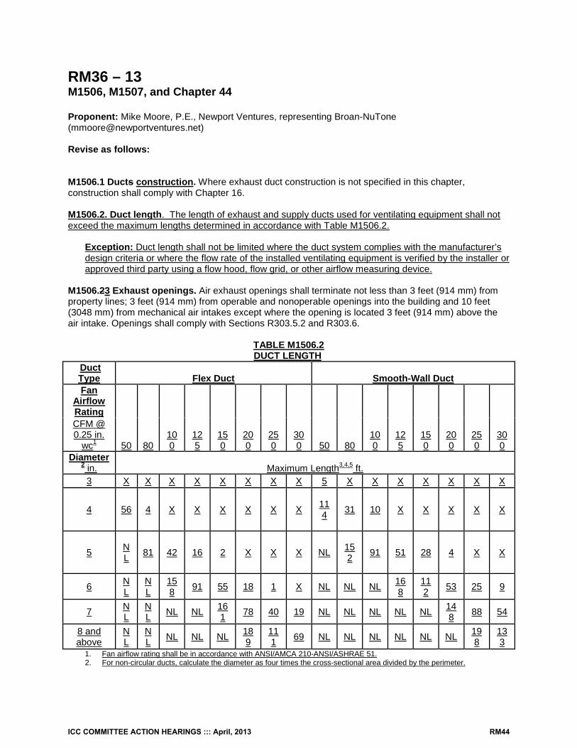
RM36 – 13 M1506, M1507, and Chapter 44 Proponent: Mike Moore, P.E., Newport Ventures, representing Broan-NuTone ([email protected]) Revise as follows: M1506.1 Ducts construction. Where exhaust duct construction is not specified in this chapter, construction shall comply with Chapter 16. M1506.2. Duct length. The length of exhaust and supply ducts used for ventilating equipment shall not exceed the maximum lengths determined in accordance with Table M1506.2.
Exception: Duct length shall not be limited where the duct system complies with the manufacturer’s design criteria or where the flow rate of the installed ventilating equipment is verified by the installer or approved third party using a flow hood, flow grid, or other airflow measuring device.
M1506.23 Exhaust openings. Air exhaust openings shall terminate not less than 3 feet (914 mm) from property lines; 3 feet (914 mm) from operable and nonoperable openings into the building and 10 feet (3048 mm) from mechanical air intakes except where the opening is located 3 feet (914 mm) above the air intake. Openings shall comply with Sections R303.5.2 and R303.6.
TABLE M1506.2 DUCT LENGTH
Duct Type Flex Duct Smooth-Wall Duct Fan
Airflow Rating
50 80 100
125
150
200
250
300 50 80
100
125
150
200
250
300
CFM @ 0.25 in.
wc1 Diameter
2 in. Maximum Length3,4,5 ft. 3 X X X X X X X X 5 X X X X X X X
4 56 4 X X X X X X 114 31 10 X X X X X
5 NL 81 42 16 2 X X X NL 15
2 91 51 28 4 X X
6 NL
NL
158 91 55 18 1 X NL NL NL 16
8 112 53 25 9
7 NL
NL NL NL 16
1 78 40 19 NL NL NL NL NL 148 88 54
8 and above
NL
NL NL NL NL 18
9 111 69 NL NL NL NL NL NL 19
8 133
1. Fan airflow rating shall be in accordance with ANSI/AMCA 210-ANSI/ASHRAE 51. 2. For non-circular ducts, calculate the diameter as four times the cross-sectional area divided by the perimeter.
ICC COMMITTEE ACTION HEARINGS ::: April, 2013 RM44
3. This table assumes that elbows are not used. Fifteen feet (5 m) of allowable duct length shall be deducted for each elbow installed in the duct run.
4. NL = no limit on duct length of this size. 5. X = not allowed, Any length of duct of this size with assumed turns and fittings will exceed the rated pressure drop.
M1507.1 General. Where local exhaust or whole-house mechanical ventilation is provided, the equipment shall be designed in accordance with this section. M1507.2 Flow Rate Verification. The flow rate for ventilating equipment shall be verified in accordance with ANSI/AMCA 210-ANSI/ASHRAE 51 or the flow rate shall be verified by the installer or approved third party using a flow hood, flow grid, or other airflow measuring device. Add new standard to Chapter 44 as follows: ANSI/AMCA 210-ANSI/ASHRAE 51-07, Laboratory Methods of Testing Fans for Aerodynamic Performance Rating. Reason: Section M1507 establishes the minimum design flow rates required for local exhaust and whole house mechanical ventilation (WHMV) fans. However, field tests of ventilating fans often show that actual flow rates fall short of design. Failure of fans to meet design rates can generally be attributed to one of two reasons: either the ductwork is poorly matched to the fan, or the fan’s actual airflow does not match its label (i.e., has not been verified via a standardized laboratory test). By providing a prescriptive duct sizing table, this proposal takes the guess work out of whether a fan should operate per the design rate. By requiring that either the fan flow rate be verified by the manufacturer in accordance with ANSI/AMCA 210-ANSI/ASHRAE 51 or be field verified by the installer or approved third party, this proposal provides a minimum level of quality assurance and control to the installation of ventilation fans.
The proposed table is taken directly from ASHRAE 62.2-2010, addendum F. Confirmation that a ventilation fan’s flow rate is in compliance with ANSI/AMCA 210-ANSI/ASHRAE 51 is as simple as looking for an HVI sticker in the fan housing. Ventilating fans exceeding the maximum CFM in Table M1506.2 would comply with Section M1506.2 by using the exception (i.e., installing ducts in accordance with the manufacturer’s design criteria or by field confirmation of the flow rate). Cost Impact: Incremental costs associated with this proposal are expected to be minimal to zero, since this proposal reflects the minimum design practice needed to ensure that installed rates match design rates. Analysis: A review of the standard proposed for inclusion in the code, [ANSI/AMCA 210-ANSI/ASHRAE 51-07] with regard to the ICC criteria for referenced standards (Section 3.6 of CP#28) will be posted on the ICC website on or before April 1, 2013. RM36-13 Public Hearing: Committee: AS AM D Assembly: ASF AMF DF
M1506.2 (NEW)-RM-MOORE.DOC
ICC COMMITTEE ACTION HEARINGS ::: April, 2013 RM45
RM37 – 13 202, M1506.2; R303.5, R303.5.1, R303.5.2 THIS IS A 2 PART CODE CHANGE. BOTH PARTS WILL BE HEARD BY THE IRC-PLUMBING AND MECHANICAL COMMITTEE AS 2 SEPARATE CODE CHANGES. SEE THE TENTATIVE HEARING ORDER FOR THIS COMMITTEE. Proponent: Mike Moore, P.E., Newport Ventures, representing Broan-NuTone ([email protected]) PART I - IRC MECHANICAL Add new definition as follows: ENVIRONMENTAL AIR. Air that is conveyed to or from occupied areas through ducts that are not part of the heating or air-conditioning system, such as ventilation for human usage, domestic kitchen range exhaust, bathroom exhaust and domestic clothes dryer exhaust. Revise text as follows: M1506.2 Exhaust openings. Air exhaust openings shall terminate not less than 3 feet (914 mm) from property lines; 3 feet (914 mm) from operable and nonoperable openings into the building and 10 feet (3048 mm) from mechanical air intakes except where the opening is located 3 feet (914 mm) above the air intake. Openings shall comply with Sections R303.5.2 and R303.6. PART II - IRC BUILDING R303.5 Opening location. Outdoor intake and exhaust openings shall be located in accordance with Sections R303.5.1 and R303.5.2. R303.5.1 Intake openings. Mechanical and gravity outdoor air intake openings shall be located a minimum of 10 feet (3048 mm) from any hazardous or noxious contaminant source, such as vents, chimneys, plumbing vents, streets, alleys, parking lots and loading docks, except as otherwise specified in this code. Where a source of contaminant source is located within 10 feet (3048 mm) of an intake opening, such opening shall be located not less than 3 feet (914 mm) below the contaminant source. For the purpose of this section, environmental air other than domestic clothes dryer exhaust the exhaust from dwelling unit toilet rooms, bathrooms and kitchens shall not be considered as hazardous or noxious. R303.5.2 Exhaust openings. Exhaust air shall not be directed onto walkways. Air exhaust openings shall terminate not less than: 3 feet (914 mm) from property lines; 3 feet (914 mm) from operable and nonoperable openings into the building; and 10 feet (3048 mm) from mechanical air intakes except where the exhaust opening is located not less than 3 feet (914 mm) above the air intake.
Exception: The minimum termination distances from the building’s operable openings, nonoperable openings, and mechanical air intakes shall not be required where the exhaust source is environmental air other than domestic clothes dryer exhaust.
Reason: The language on exhaust and intake openings is redundant and confusing in that it is spread throughout the code, and permits exhausts to be located near intakes but does not permit intakes to be located near exhausts. This change seeks to simplify the language, reorganize into one section, and ensure that the allowances for intakes are consistent with the allowances for exhaust. Improvements include the following:
1. Include exhaust from occupied areas among the list of non-hazardous exhaust. R303.5.1 states that exhaust from toilet rooms, bathrooms, and kitchens shall not be considered as hazardous. This list is not comprehensive, notably excluding exhaust from occupied areas like living rooms or bedrooms, which are likely to contain even less contaminants than exhaust from toilet rooms, bathrooms, and kitchens. To fix this, I’ve borrowed the definition of “Environmental Air” from
ICC COMMITTEE ACTION HEARINGS ::: April, 2013 RM46
the IMC and excluded clothes dryer exhaust and parking garage exhaust, since this section does not currently permit these.
2. Move the text of M1506.2 to R303.5.2, and reduce the text of M1506.2 to a reference. 3. Add an exception to R303.5.2 that aligns with the language in R303.5.1. To simplify, the code currently states that A can
be close to B, but B can’t be close to A, which doesn’t make sense. R303.5.1 specifically eliminates the minimum separation distance between intakes and exhaust terminations of toilet rooms, bathrooms, or kitchens. However, M1506.2 still states that all exhaust terminations must still observe minimum separation distances from intakes. Adding the exception to R303.5.2 brings consistency to these two sections.
Cost Impact: No impact. RM37-13 PART I - IRC MECHANICAL Public Hearing: Committee: AS AM D Assembly: ASF AMF DF PART II - IRC BUILDING Public Hearing: Committee: AS AM D Assembly: ASF AMF DF
M1506.2-RM-MOORE.DOC
ICC COMMITTEE ACTION HEARINGS ::: April, 2013 RM47
RM38 – 13 M1506.2 Proponent: Mike Winkler, Chair of the IRC Interpretations Committee, representing our committee Revise as follows: M1506.2 Exhaust openings. Location of exhaust outlets. Air Exhaust air openings outlets shall terminate not less than 3 feet (914mm) from property lines. Exhaust air outlets shall terminate not less than 3 feet from operable and non-operable openings that have the potential for allowing exhaust air back into the building, except where the exhaust air outlet is located not less 3 feet (914mm) above such openings. and Exhaust air outlets shall terminate not less than 10 feet (3048mm) from mechanical air intakes, except where the exhaust air outlet opening is located not less than 3 feet (914mm) above the mechanical air intake. Reason: The IRC interpretation committee is attempting to revise the language for two reasons. First, to have the title be consistent with the IMC and second, to clarify the intent. The IRC interpretation committee received a request for a formal interpretation and could not reach a consensus regarding what exactly the current text requires. A “non-operable” opening could be viewed as a fixed louver or as a fixed glass window panel. Neither can be operated but one will let air into the building and the other will not.
The text is also revised so that the terms “opening” and “exhaust air outlet” are used consistently throughout the section. The current text stated opening where it meant exhaust outlet near the end of the 1st sentence. The exhaust outlets are now clearly distinct from the “openings”, since “opening” in this context refers to air intake openings. The current text stated that exhaust openings had to be exactly 3 feet above the air intake, so, if it was 4 feet above, the allowance would not apply. The text was poorly formatted in a long run-on sentence which made it unclear if the exception for being 3 foot above applied only to the mechanical air intakes or if it also applied to other openings that could let exhaust back into the building. Breaking the run-on sentence into separate thoughts makes it perfectly clear that it applies in both cases. The proposed revisions mean to clarify what the interpretation committee believes to be the actual intent of this section, as well improve to readability of the text overall. Cost Impact: The code change proposal will not increase the cost of construction. RM38-13 Public Hearing: Committee: AS AM D Assembly: ASF AMF DF
M1506.2-RM-WINKLER.DOC
ICC COMMITTEE ACTION HEARINGS ::: April, 2013 RM48
RM39 – 13 M1506.3 (New) Proponent: David Hall CFM, Georgetown Texas representing the ICC PMG Code Action Committee ([email protected]) Add new text as follows: M1506.3 Exhaust fans. Exhaust fans shall not discharge through common ducts. Reason: Some installers attempt to join the outlets of two or more bathroom exhaust fans into a common discharge duct. This presents multiple problems including: 1) The common duct is typically undersized which prevents the fans from achieving their intended flow rate. 2) The backdraft dampers in such fans are not designed to be airtight or to prevent reverse flow from other fans. The result is that discharge from one fan is pushed back through any fan that is not operating. 3) The fan manufacturers provide no guidance for this nor do they recommend the practice. 4) The tees used for such arrangements often create flow resistance and direct the flow such that the air streams oppose each other. 5) If fans in different dwelling units were joined to a common duct, there would be direct communication between the two dwellings.
This proposal is submitted by the ICC Plumbing, Mechanical and Fuel Gas Code Action Committee (PMGCAC). The PMGCAC was established by the ICC Board of Directors to pursue opportunities to improve and enhance an assigned International Code or portion thereof. This includes both the technical aspects of the codes as well as the code content in terms of scope and application of referenced standards. Since its inception in July, 2011, the PMGCAC has held 2 open meetings, multiple conference calls and multiple workgroup calls which included members of the PMGCAC. Interested parties also participated in all of the meetings and conference calls to discuss and debate the proposed changes. Cost Impact: The code change proposal will not increase the cost of construction.
RM39-13 Public Hearing: Committee: AS AM D Assembly: ASF AMF DF
M1506.3 (NEW)-RM-HALL-PMGCAC
ICC COMMITTEE ACTION HEARINGS ::: April, 2013 RM49
RM40 – 13 M1507.3 Proponent: Mike Moore, P.E., Newport Ventures, representing Broan-NuTone ([email protected]) Add new text as follows: M1507.3 Sound Ratings. Ventilation fans shall have a sound performance in accordance with the following:
1. For whole-house or continuous ventilation fans: maximum of 1.0 sone. 2. For intermittent local exhaust fans: maximum of 3.0 sone.
Exceptions:
1. Fans having a maximum rated airflow exceeding 400 cfm. 2. HVAC air handlers and fans mounted with not less than 4 ft (1 m) of ductwork between
the fan and the intake grille. (Renumber subsequent sections.) Reason: Ventilation fans only work when they’re turned on, and the number one reason typically given by home owners for not turning on a ventilation fan is, “it’s too noisy”.1,2,3 As homes have become tighter, the use of whole house mechanical ventilation (WHMV) for maintaining acceptable indoor air quality and local exhaust fans to capture and expel pollutants at their source (esp. in bathrooms and kitchens) has become necessary. Installing a fan that will not be operated due to noise is a disservice to the homeowner, a liability to their health, and a risk to the home’s durability (can lead to excess condensation on windows, increased potential for mold and rot, etc.).
This proposed requirement mirrors that adopted by the state of California and ASHRAE 62.2. Maximum sone levels have been enforced by Washington State’s code since the late 1980s. The sone values proposed above have been widely accepted by the industry. A sone is linear measure of loudness, meaning that a three sone fan is three times as loud as a one sone fan. The Home Ventilating Institute describes the sone scale as follows:
• 0.5 sone: rustling leaves • 1.0 sone: refrigerator • 3.0 sone: typical office • 4.0 sone: typical television operating
For a fan which operates only occasionally (like a bath fan), a maximum sone level of 3.0 is considered acceptable. For a fan
which is designed to operate continuously (e.g., a WHMV fan), a maximum sone level of 1.0 is necessary to avoid occupants turning off the fan from noise irritation.
The overwhelming majority of intermittent exhaust fans listed in the HVI products directory achieve a sone rating of 3 or less, so this requirement weeds out only the worst performers and therefore should have little to no impact to builders when specifying HVI certified products. The 1.0 sone requirement for WHMV fans has been achieved by over 500 fans listed in the Home Ventilating Institute’s certified product directory (www.hvi.org). Further, the 1.0 sone requirement for WHMV fans can be viewed as a cost-saving measure. To find out why, see the cost impact section below. References:
1. Nagda, N. L., M. D. Koontz, R. C. Fortmann, and I. H. Billick (1989) "Prevalence, Use, and Effectiveness of Range-Exhaust Fans.ʺ Environment International 15(1-6): 615–620.
2. Parrott, K., J. Emmel, and J. Beamish (2003) “Use of Kitchen Ventilation: Impact on Indoor Air Quality.” In The Forum for Family and Consumer Issues, edited, North Carolina State University, Raleigh North Carolina.
3. Singer, B.C., W. W. Delp, and M. G. Apte (2011) Experimental Evaluation of Installed Cooking Exhaust Fan Performance. LBNL-4183E. Ernest Orlando Lawrence Berkeley National Laboratory, Berkeley, California.
4. Email communication with Don Stevens, Panasonic, dated 11/29/2012. Cost Impact: Whole house mechanical ventilation (WHMV) fans are required by IRC N1103.5.1 to have a minimum fan efficacy greater than or equal to minimum required for Energy Star fans, meaning that whole-house mechanical ventilation fans are likely to also be Energy Star rated. To achieve the Energy Star rating, a fan must have a noise rating less than or equal to 1.0 sone. So, a WHMV fan which meets the energy efficacy requirements of the IRC is also likely to have a sone rating of 1.0 or less; therefore, no additional costs are expected from this change. Supposing a jurisdiction does not adopt Chapter 11 of the IRC, a builder could theoretically install a WHMV fan that has a sone rating of 3 or higher. If he does, the homeowners are not likely to operate the fan
ICC COMMITTEE ACTION HEARINGS ::: April, 2013 RM50
due to unacceptable noise levels, and when they experience poor indoor air quality as a result, a call-back is the next step. The cost of a call-back far outweighs the incremental cost of a 1.0 sone WHMV fan, making the 1.0 sone WHMV fan a cost-savings measure for those builders who are not currently specifying them. RM40-13 Public Hearing: Committee: AS AM D Assembly: ASF AMF DF
M1507.3 (NEW)-RM-MOORE.DOC
ICC COMMITTEE ACTION HEARINGS ::: April, 2013 RM51
RM41 – 13 M1507.3.1 Proponent: Jerry Anderson, City of Overland Park, KS, representing self ([email protected]) Revise as follows:
M1507.3.1 System design. The whole-house ventilation system shall consist of one or more supply or exhaust fans, or a combination of such, and associated ducts and controls. Local exhaust or supply fans are permitted to serve as such a system. Systems designed to supply air shall supply outdoor air. Outdoor air ducts connected to the return side of an air handler shall be considered to provide supply ventilation.
Reason: The purpose of this code change is to make it clear that the airflow for mechanical ventilation systems designed to supply air shall take that air from the outdoors. The sentence being deleted is no longer necessary. It doesn’t matter how the outdoor air is distributed. What matters in this code section is that supply air comes from the outdoors. Cost Impact: No cost associated with this change. RM41-13 Public Hearing: Committee: AS AM D Assembly: ASF AMF DF
M1507.3.1-RM-ANDERSON.DOC
ICC COMMITTEE ACTION HEARINGS ::: April, 2013 RM52
RM42 – 13 M1507.3.2 Proponent: Jerry Anderson, representing the City of Overland Park, Kansas Revise as follows: M1507.3.2 System controls. The Whole-house mechanical ventilation systems designed for intermittent operation in accordance with Section M1507.3.3 shall utilize a 24 hour timer control capable of cycling the fan(s) on and off as needed. Whole-house mechanical ventilation systems shall be provided with controls that enable manual override.
Reason: The purpose of the code change is to require an automatic timer switch for those fans that are designed to be run intermittently. In the exception to Section M1507.3.3 the code allows for whole-house mechanical ventilation systems to be operated intermittently. The word “intermittently” can mean different things to different people. A local exhaust fan operated manually by a wall switch could easily be considered to be an intermittent fan system. I think that the code assumes that there will be some sort of automation built into intermittent systems. I don’t think that the code intends the systems to be manually operated. Therefore, I have inserted language which makes it clear that a manual switch is not allowed. Cost Impact: There would be a small cost associated with the timer switch, if they are not already being provide for. RM42-13 Public Hearing: Committee: AS AM D Assembly: ASF AMF DF
M1507.3.2-RM-ANDERSON.DOC
ICC COMMITTEE ACTION HEARINGS ::: April, 2013 RM53
RM43 – 13 M1507.3.3, Table M1507.3.3 (2) Proponent: Mike Moore, P.E., Newport Ventures, representing Broan-NuTone ([email protected]) Revise as follows: M1507.3.3 Mechanical ventilation rate. The whole house mechanical ventilation system shall provide outdoor air at a continuous rate of not less than that determined in accordance with Table M1507.3.3(1).
Exception: The whole-house mechanical ventilation system is permitted not required to operate intermittently continuously where the system has controls that enable operation for not less than 25-percent 1-hour of each 4-hour segment period. The average and the ventilation rate over the 4-hour period shall be at least that prescribed in Table M1507.3.3(1). is multiplied by the factor determined in accordance with Table M1507.3.3(2).
TABLE M1503.3.3(2)
INTERMITTENT WHOLE-HOUSE MECHANICAL VENTILATION RATE FACTORSa,b RUN-TIME PERCENTAGE IN EACH 4-HOUR SEGMENT 25% 33% 50% 66% 75% 100%
Factora 4 3 2 1.5 1.3 1.0 a. For ventilation system run time values between those given, the factors are permitted to be determined by interpolation. b. Extrapolation beyond the table is prohibited. Reason: This language simplifies this section and provides consistency with the 2015 IMC requirements for dwelling units. Cost Impact: No impact on cost. RM_-13 Public Hearing: Committee: AS AM D Assembly: ASF AMF DF
M1507.3.3-RM-MOORE.DOC
ICC COMMITTEE ACTION HEARINGS ::: April, 2013 RM54
RM44 – 13 M1508.1 (New) Proponent: Craig Conner, representing self Add text as follows: M1508.1 Venting and Depressurization. Gas-and oil-fired space- heating and gas-and oil-fired water- heating combustion appliances in new dwelling units shall comply with at least one of the following:
1. Space- heating and water-heating combustion appliances located within a dwelling unit’s air barrier shall be of the direct-vent type.
2. Space heating appliances and water heating appliances located within a dwelling unit’s air barrier shall be of the direct- vent or mechanical draft type. Mechanical ventilation shall be provided in accordance with Section M1507. Makeup air shall be provided for each of the dwelling unit’s three largest exhaust systems at a rate approximately equal to or greater than the design exhaust rate. Makeup air systems shall be equipped with not less than one gravity or motorized damper. Motorized dampers shall be automatically controlled to operate simultaneously with the exhaust systems.
3. Space-heating and water-heating combustion appliances shall not be located within a dwelling unit’s air barrier. For purposes of this option, appliances located in a mechanical room separated from the conditioned space by an air barrier shall be considered to be outside of a dwelling unit’s air barrier. Exceptions: The section shall not apply to:
1. Dwelling units with a tested air tightness of greater than 3 ACH50 2. Dwelling units having a tested depressurization that is within the limits specified by an
approved test. Reason: Backdrafting combustion appliances can lead to serious health consequences. The IECC and common practices are increasing the potential for backdrafting in homes. The IECC requires a building envelope tested to be 3 ACH50 or less in the middle and northern climate zones. This change is designed to greatly reduce the likelihood of backdrafting in those tight homes.
Back drafting is most likely to occur if three things are true- construction is airtight, exhaust-only ventilation is used, and atmospherically vented (natural draft) combustion appliances are in conditioned spaces. The IECC has both testing and prescriptive measures to increase envelope tightness and should routinely produce airtight construction. Mechanical ventilation is required for residences, with the least expensive form of mechanical ventilation being the exhaust-only ventilation fans already in common use. The energy code no longer encourages more efficient condensing furnaces by recognizing their high energy efficiency; thereby, removing some of the motivation for condensing furnaces. The trend towards large exhaust fans, such as kitchen hoods, also contributes to the problem. This combination is a recipe for back drafting problems.
The proposed change gives several options. These options prevent back drafting by eliminating at least one of major contributor; eliminating the natural draft (atmospherically vented) combustion appliances, eliminating the large exhaust-only ventilation, or taking the combustion outside the air barrier. An exception adds a depressurization test option, which tests for excessive depressurization levels in dwelling units. Cost Impact: The code change proposal will not increase the cost of construction. RM44-13 Public Hearing: Committee: AS AM D Assembly: ASF AMF DF
M1508 (NEW)-RM-CONNER.DOC
ICC COMMITTEE ACTION HEARINGS ::: April, 2013 RM55
RM45 – 13 M1601.1.1 Proponent: David Hall CFM, Georgetown Texas representing the ICC PMG Code Action Committee ([email protected]) Revise as follows: M1601.1.1 Above-ground duct systems. Above-ground duct systems shall conform to the following:
1. Equipment connected to duct systems shall be designed to limit discharge air temperature to a maximum of 250ºF (121ºC).
2. Factory-made air ducts shall be constructed of Class 0 or Class 1 materials as designated in Table M1601.1.1(1).
3. Fibrous duct construction shall conform to the SMACNA Fibrous Glass Duct Construction Standards or NAIMA Fibrous Glass Duct Construction Standards.
4. Minimum thickness of metal duct material shall be as listed in Table M1601.1.1(2). Galvanized steel shall conform to ASTM A 653. Metallic ducts shall be fabricated in accordance with SMACNA Duct Construction Standards Metal and Flexible.
5. Use of gypsum products to construct return air ducts or plenums is permitted, provided that the air temperature does not exceed 125°F (52°C) and exposed surfaces are not subject to condensation.
6. Duct systems shall be constructed of materials having a flame spread index not greater than 200.
7.6. Stud wall cavities and the spaces between solid floor joists to be used as air plenums shall comply with the following conditions: 7.1 6.1. These cavities or spaces shall not be used as a plenum for supply air. 7.2 6.2. These cavities or spaces shall not be part of required fire-resistance-rated assembly. 7.3 6.3. Stud wall cavities shall not convey air from more than one floor level. 7.4 6.4 Stud wall cavities and joist-space plenum shall be isolated from adjacent concealed
spaces by tight-fitting fire blocking in accordance with Section R602.8. 7.5 6.5. Stud wall cavities in the outside walls of building envelope assemblies shall not be
utilized as air plenums. Reason: Considering the subject of items #2 and #3, it is not apparent what item #6 is intended to address. Item #2 requires factory-made ducts to have a maximum flame spread index of 50, so why does item #6 state an index of 200 maximum?? Current section M1601.2 requires factory-made ducts to comply with UL 181, and UL 181 requires all ducts to have a maximum flame spread index of 50. If item #6 addresses factory-made ducts, then it conflicts with Item #2 and Section M1601.2. If item #6 was intended to address plastic ducts, it then begs the question as whether plastic ducts are allowed above ground in dwellings. An ICC formal interpretation on this exact question was issued and it states that plastic ducts are allowed above ground if they can meet class 0 or class 1, meaning that the maximum flame spread index could not exceed 50. With the broad definition of “duct systems” in the IRC, the purpose of item #6 is even more unclear. Item #6 is confusing and appears to be unnecessary because the code already addresses the various duct materials in other text.
This proposal is submitted by the ICC Plumbing, Mechanical and Fuel Gas Code Action Committee (PMGCAC). The PMGCAC was established by the ICC Board of Directors to pursue opportunities to improve and enhance an assigned International Code or portion thereof. This includes both the technical aspects of the codes as well as the code content in terms of scope and application of referenced standards. Since its inception in July, 2011, the PMGCAC has held 2 open meetings, multiple conference calls and multiple workgroup calls which included members of the PMGCAC. Interested parties also participated in all of the meetings and conference calls to discuss and debate the proposed changes. Cost Impact: The code change proposal will not increase the cost of construction.
RM45-13 Public Hearing: Committee: AS AM D Assembly: ASF AMF DF
M1601.1.1 #1-RM-HALL-PMGCAC
ICC COMMITTEE ACTION HEARINGS ::: April, 2013 RM56
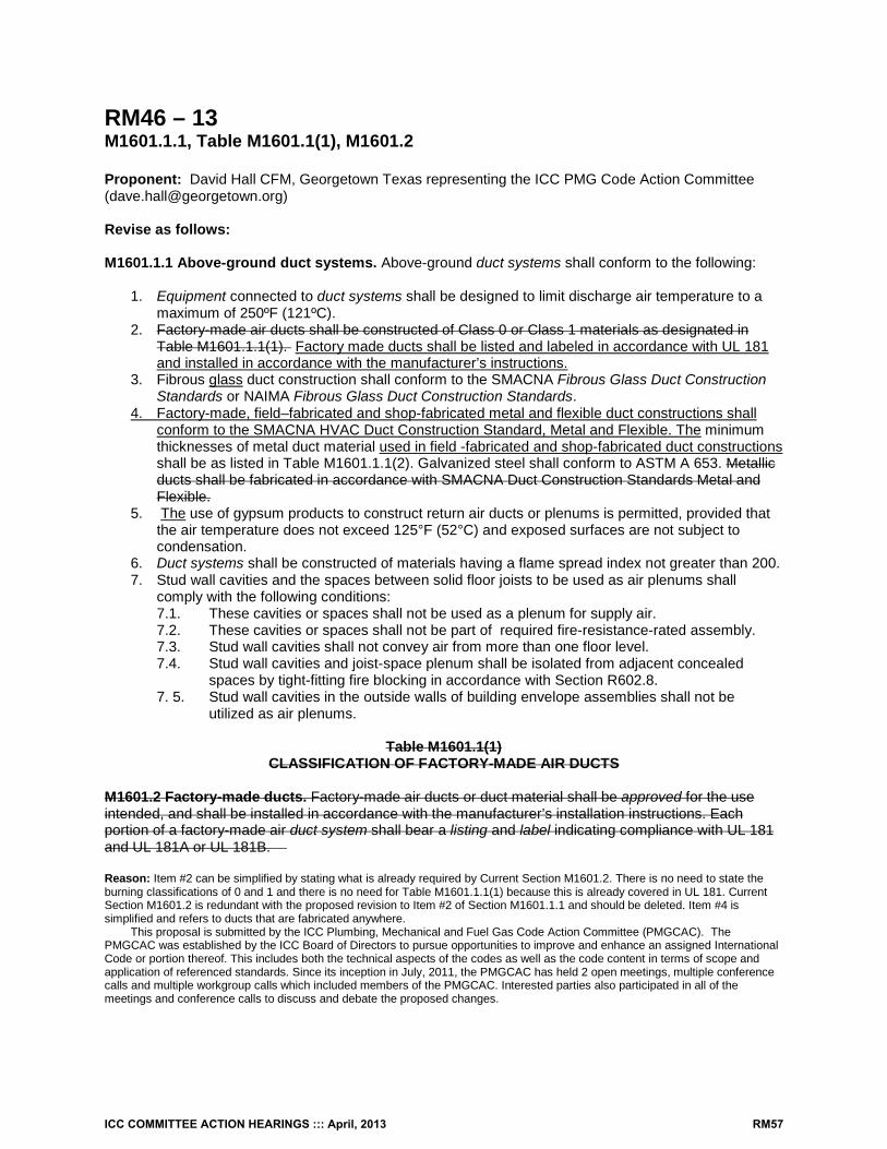
RM46 – 13 M1601.1.1, Table M1601.1(1), M1601.2 Proponent: David Hall CFM, Georgetown Texas representing the ICC PMG Code Action Committee ([email protected]) Revise as follows: M1601.1.1 Above-ground duct systems. Above-ground duct systems shall conform to the following:
1. Equipment connected to duct systems shall be designed to limit discharge air temperature to a maximum of 250ºF (121ºC).
2. Factory-made air ducts shall be constructed of Class 0 or Class 1 materials as designated in Table M1601.1.1(1). Factory made ducts shall be listed and labeled in accordance with UL 181 and installed in accordance with the manufacturer’s instructions.
3. Fibrous glass duct construction shall conform to the SMACNA Fibrous Glass Duct Construction Standards or NAIMA Fibrous Glass Duct Construction Standards.
4. Factory-made, field–fabricated and shop-fabricated metal and flexible duct constructions shall conform to the SMACNA HVAC Duct Construction Standard, Metal and Flexible. The minimum thicknesses of metal duct material used in field -fabricated and shop-fabricated duct constructions shall be as listed in Table M1601.1.1(2). Galvanized steel shall conform to ASTM A 653. Metallic ducts shall be fabricated in accordance with SMACNA Duct Construction Standards Metal and Flexible.
5. The use of gypsum products to construct return air ducts or plenums is permitted, provided that the air temperature does not exceed 125°F (52°C) and exposed surfaces are not subject to condensation.
6. Duct systems shall be constructed of materials having a flame spread index not greater than 200. 7. Stud wall cavities and the spaces between solid floor joists to be used as air plenums shall
comply with the following conditions: 7.1. These cavities or spaces shall not be used as a plenum for supply air. 7.2. These cavities or spaces shall not be part of required fire-resistance-rated assembly. 7.3. Stud wall cavities shall not convey air from more than one floor level. 7.4. Stud wall cavities and joist-space plenum shall be isolated from adjacent concealed
spaces by tight-fitting fire blocking in accordance with Section R602.8. 7. 5. Stud wall cavities in the outside walls of building envelope assemblies shall not be
utilized as air plenums.
Table M1601.1(1) CLASSIFICATION OF FACTORY-MADE AIR DUCTS
M1601.2 Factory-made ducts. Factory-made air ducts or duct material shall be approved for the use intended, and shall be installed in accordance with the manufacturer’s installation instructions. Each portion of a factory-made air duct system shall bear a listing and label indicating compliance with UL 181 and UL 181A or UL 181B. Reason: Item #2 can be simplified by stating what is already required by Current Section M1601.2. There is no need to state the burning classifications of 0 and 1 and there is no need for Table M1601.1.1(1) because this is already covered in UL 181. Current Section M1601.2 is redundant with the proposed revision to Item #2 of Section M1601.1.1 and should be deleted. Item #4 is simplified and refers to ducts that are fabricated anywhere.
This proposal is submitted by the ICC Plumbing, Mechanical and Fuel Gas Code Action Committee (PMGCAC). The PMGCAC was established by the ICC Board of Directors to pursue opportunities to improve and enhance an assigned International Code or portion thereof. This includes both the technical aspects of the codes as well as the code content in terms of scope and application of referenced standards. Since its inception in July, 2011, the PMGCAC has held 2 open meetings, multiple conference calls and multiple workgroup calls which included members of the PMGCAC. Interested parties also participated in all of the meetings and conference calls to discuss and debate the proposed changes.
ICC COMMITTEE ACTION HEARINGS ::: April, 2013 RM57
Cost Impact: The code change proposal will not increase the cost of construction.
RM46-13 Public Hearing: Committee: AS AM D Assembly: ASF AMF DF
M1601.1.1 #2-RM-HALL-PMGCAC
ICC COMMITTEE ACTION HEARINGS ::: April, 2013 RM58
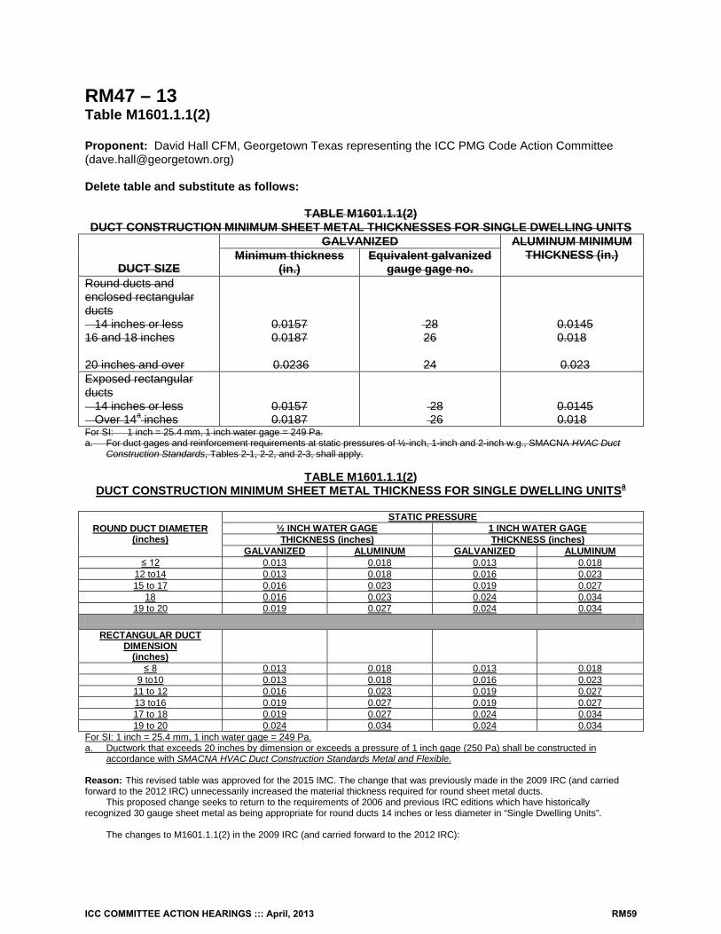
RM47 – 13 Table M1601.1.1(2) Proponent: David Hall CFM, Georgetown Texas representing the ICC PMG Code Action Committee ([email protected]) Delete table and substitute as follows:
TABLE M1601.1.1(2) DUCT CONSTRUCTION MINIMUM SHEET METAL THICKNESSES FOR SINGLE DWELLING UNITS
DUCT SIZE
GALVANIZED ALUMINUM MINIMUM THICKNESS (in.) Minimum thickness
(in.) Equivalent galvanized
gauge gage no. Round ducts and enclosed rectangular ducts 14 inches or less 16 and 18 inches 20 inches and over
0.0157 0.0187
0.0236
28 26
24
0.0145 0.018
0.023
Exposed rectangular ducts 14 inches or less Over 14a inches
0.0157 0.0187
28 26
0.0145 0.018
For SI: 1 inch = 25.4 mm, 1 inch water gage = 249 Pa. a. For duct gages and reinforcement requirements at static pressures of ½-inch, 1-inch and 2-inch w.g., SMACNA HVAC Duct
Construction Standards, Tables 2-1, 2-2, and 2-3, shall apply.
TABLE M1601.1.1(2) DUCT CONSTRUCTION MINIMUM SHEET METAL THICKNESS FOR SINGLE DWELLING UNITSa
ROUND DUCT DIAMETER (inches)
STATIC PRESSURE ½ INCH WATER GAGE 1 INCH WATER GAGE THICKNESS (inches) THICKNESS (inches)
GALVANIZED ALUMINUM GALVANIZED ALUMINUM ≤ 12 0.013 0.018 0.013 0.018
12 to14 0.013 0.018 0.016 0.023 15 to 17 0.016 0.023 0.019 0.027
18 0.016 0.023 0.024 0.034 19 to 20 0.019 0.027 0.024 0.034
RECTANGULAR DUCT
DIMENSION (inches)
≤ 8 0.013 0.018 0.013 0.018 9 to10 0.013 0.018 0.016 0.023
11 to 12 0.016 0.023 0.019 0.027 13 to16 0.019 0.027 0.019 0.027 17 to 18 0.019 0.027 0.024 0.034 19 to 20 0.024 0.034 0.024 0.034
For SI: 1 inch = 25.4 mm, 1 inch water gage = 249 Pa. a. Ductwork that exceeds 20 inches by dimension or exceeds a pressure of 1 inch gage (250 Pa) shall be constructed in
accordance with SMACNA HVAC Duct Construction Standards Metal and Flexible. Reason: This revised table was approved for the 2015 IMC. The change that was previously made in the 2009 IRC (and carried forward to the 2012 IRC) unnecessarily increased the material thickness required for round sheet metal ducts.
This proposed change seeks to return to the requirements of 2006 and previous IRC editions which have historically recognized 30 gauge sheet metal as being appropriate for round ducts 14 inches or less diameter in “Single Dwelling Units”.
The changes to M1601.1.1(2) in the 2009 IRC (and carried forward to the 2012 IRC):
ICC COMMITTEE ACTION HEARINGS ::: April, 2013 RM59
1. Increased cost for round sheet metal ducts 2. Did not improve safety 3. Did not improve energy performance
Cost Impact: This code change proposal will not increase the cost of construction. RM47-13 Public Hearing: Committee: AS AM D Assembly: ASF AMF DF
M1601.1.1(2)T #2-RM-HALL-PMGCAC
ICC COMMITTEE ACTION HEARINGS ::: April, 2013 RM60
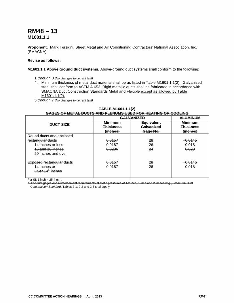
RM48 – 13 M1601.1.1 Proponent: Mark Terzigni, Sheet Metal and Air Conditioning Contractors’ National Association, Inc. (SMACNA) Revise as follows: M1601.1.1 Above ground duct systems. Above-ground duct systems shall conform to the following: 1 through 3 (No changes to current text)
4. Minimum thickness of metal duct material shall be as listed in Table M1601.1.1(2). Galvanized steel shall conform to ASTM A 653. Rigid metallic ducts shall be fabricated in accordance with SMACNA Duct Construction Standards Metal and Flexible except as allowed by Table M1601.1.1(2).
5 through 7 (No changes to current text)
TABLE M1601.1.1(2) GAGES OF METAL DUCTS AND PLENUMS USED FOR HEATING OR COOLING
DUCT SIZE
GALVANIZED ALUMINUM Minimum Thickness (inches)
Equivalent Galvanized Gage No.
Minimum Thickness (inches)
Round ducts and enclosed rectangular ducts
14 inches or less 16 and 18 inches 20 inches and over
Exposed rectangular ducts
14 inches or Over 14a inches
0.0157 0.0187 0.0236
0.0157 0.0187
28 26 24
28 26
0.0145 0.018 0.023
0.0145 0.018
For SI: 1 inch = 25.4 mm. a. For duct gages and reinforcement requirements at static pressures of 1/2 inch, 1 inch and 2 inches w.g., SMACNA Duct
Construction Standard, Tables 2-1; 2-2 and 2-3 shall apply.
ICC COMMITTEE ACTION HEARINGS ::: April, 2013 RM61
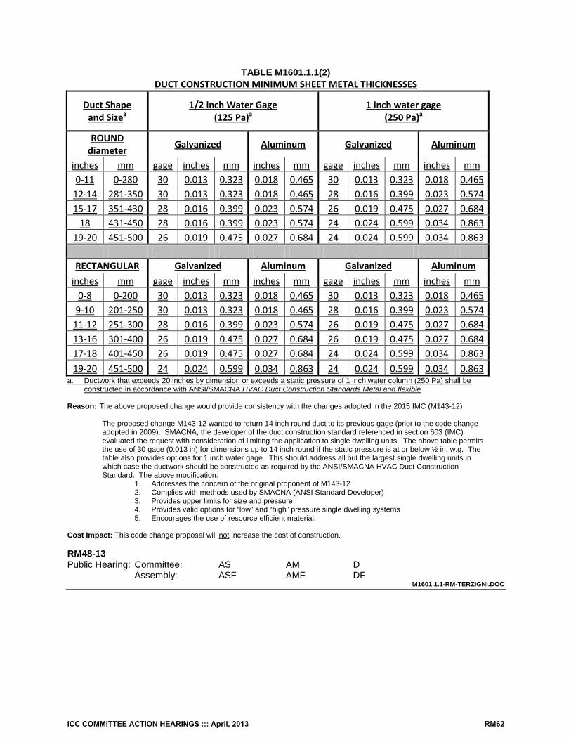
TABLE M1601.1.1(2) DUCT CONSTRUCTION MINIMUM SHEET METAL THICKNESSES
Duct Shape and Sizea
1/2 inch Water Gage (125 Pa)a
1 inch water gage (250 Pa)a
ROUND diameter Galvanized Aluminum Galvanized Aluminum
inches mm gage inches mm inches mm gage inches mm inches mm 0-11 0-280 30 0.013 0.323 0.018 0.465 30 0.013 0.323 0.018 0.465 12-14 281-350 30 0.013 0.323 0.018 0.465 28 0.016 0.399 0.023 0.574 15-17 351-430 28 0.016 0.399 0.023 0.574 26 0.019 0.475 0.027 0.684 18 431-450 28 0.016 0.399 0.023 0.574 24 0.024 0.599 0.034 0.863 19-20 451-500 26 0.019 0.475 0.027 0.684 24 0.024 0.599 0.034 0.863 RECTANGULAR Galvanized Aluminum Galvanized Aluminum inches mm gage inches mm inches mm gage inches mm inches mm 0-8 0-200 30 0.013 0.323 0.018 0.465 30 0.013 0.323 0.018 0.465 9-10 201-250 30 0.013 0.323 0.018 0.465 28 0.016 0.399 0.023 0.574 11-12 251-300 28 0.016 0.399 0.023 0.574 26 0.019 0.475 0.027 0.684 13-16 301-400 26 0.019 0.475 0.027 0.684 26 0.019 0.475 0.027 0.684 17-18 401-450 26 0.019 0.475 0.027 0.684 24 0.024 0.599 0.034 0.863 19-20 451-500 24 0.024 0.599 0.034 0.863 24 0.024 0.599 0.034 0.863 a. Ductwork that exceeds 20 inches by dimension or exceeds a static pressure of 1 inch water column (250 Pa) shall be
constructed in accordance with ANSI/SMACNA HVAC Duct Construction Standards Metal and flexible Reason: The above proposed change would provide consistency with the changes adopted in the 2015 IMC (M143-12)
The proposed change M143-12 wanted to return 14 inch round duct to its previous gage (prior to the code change adopted in 2009). SMACNA, the developer of the duct construction standard referenced in section 603 (IMC) evaluated the request with consideration of limiting the application to single dwelling units. The above table permits the use of 30 gage (0.013 in) for dimensions up to 14 inch round if the static pressure is at or below ½ in. w.g. The table also provides options for 1 inch water gage. This should address all but the largest single dwelling units in which case the ductwork should be constructed as required by the ANSI/SMACNA HVAC Duct Construction Standard. The above modification:
1. Addresses the concern of the original proponent of M143-12 2. Complies with methods used by SMACNA (ANSI Standard Developer) 3. Provides upper limits for size and pressure 4. Provides valid options for “low” and “high” pressure single dwelling systems 5. Encourages the use of resource efficient material.
Cost Impact: This code change proposal will not increase the cost of construction. RM48-13 Public Hearing: Committee: AS AM D Assembly: ASF AMF DF
M1601.1.1-RM-TERZIGNI.DOC
ICC COMMITTEE ACTION HEARINGS ::: April, 2013 RM62
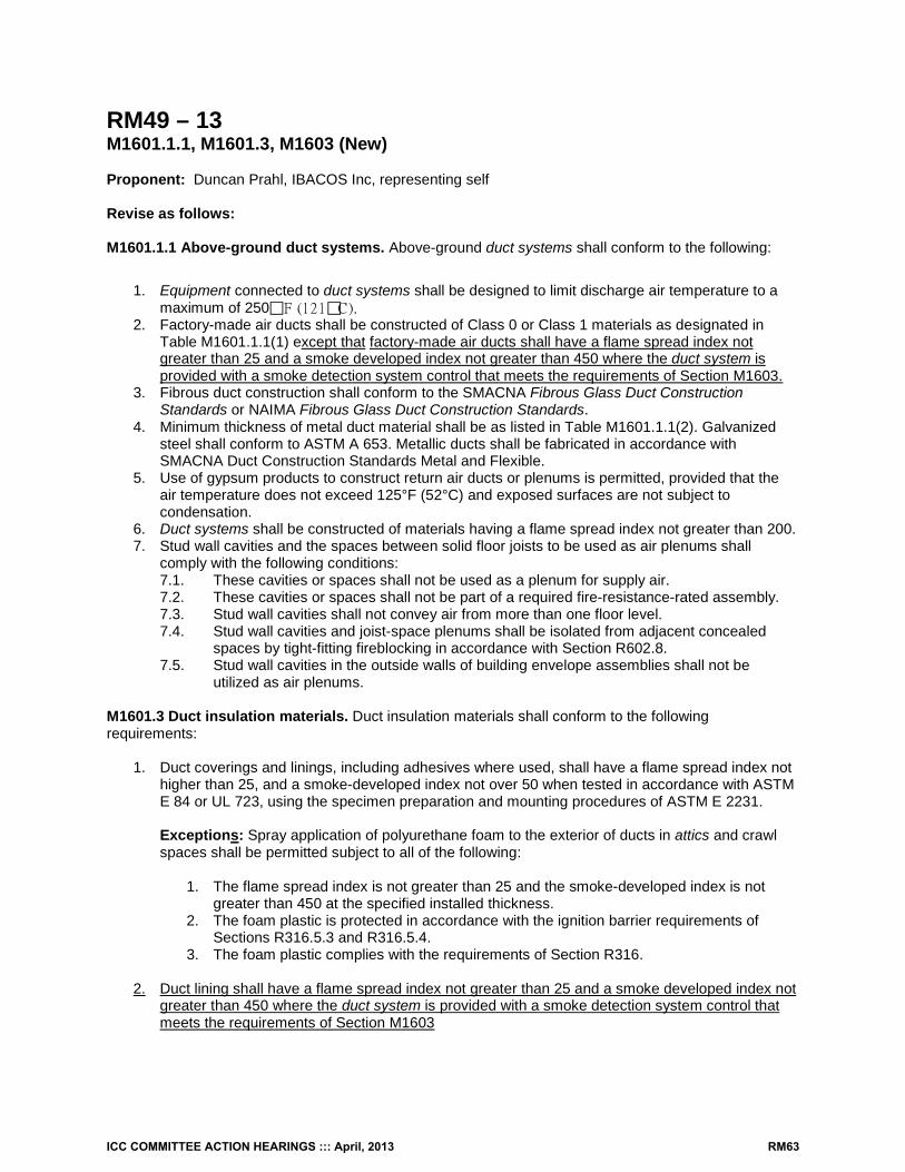
RM49 – 13 M1601.1.1, M1601.3, M1603 (New) Proponent: Duncan Prahl, IBACOS Inc, representing self Revise as follows: M1601.1.1 Above-ground duct systems. Above-ground duct systems shall conform to the following:
1. Equipment connected to duct systems shall be designed to limit discharge air temperature to a maximum of 250F (121C).
2. Factory-made air ducts shall be constructed of Class 0 or Class 1 materials as designated in Table M1601.1.1(1) except that factory-made air ducts shall have a flame spread index not greater than 25 and a smoke developed index not greater than 450 where the duct system is provided with a smoke detection system control that meets the requirements of Section M1603.
3. Fibrous duct construction shall conform to the SMACNA Fibrous Glass Duct Construction Standards or NAIMA Fibrous Glass Duct Construction Standards.
4. Minimum thickness of metal duct material shall be as listed in Table M1601.1.1(2). Galvanized steel shall conform to ASTM A 653. Metallic ducts shall be fabricated in accordance with SMACNA Duct Construction Standards Metal and Flexible.
5. Use of gypsum products to construct return air ducts or plenums is permitted, provided that the air temperature does not exceed 125°F (52°C) and exposed surfaces are not subject to condensation.
6. Duct systems shall be constructed of materials having a flame spread index not greater than 200. 7. Stud wall cavities and the spaces between solid floor joists to be used as air plenums shall
comply with the following conditions: 7.1. These cavities or spaces shall not be used as a plenum for supply air. 7.2. These cavities or spaces shall not be part of a required fire-resistance-rated assembly. 7.3. Stud wall cavities shall not convey air from more than one floor level. 7.4. Stud wall cavities and joist-space plenums shall be isolated from adjacent concealed
spaces by tight-fitting fireblocking in accordance with Section R602.8. 7.5. Stud wall cavities in the outside walls of building envelope assemblies shall not be
utilized as air plenums.
M1601.3 Duct insulation materials. Duct insulation materials shall conform to the following requirements:
1. Duct coverings and linings, including adhesives where used, shall have a flame spread index not higher than 25, and a smoke-developed index not over 50 when tested in accordance with ASTM E 84 or UL 723, using the specimen preparation and mounting procedures of ASTM E 2231.
Exceptions: Spray application of polyurethane foam to the exterior of ducts in attics and crawl spaces shall be permitted subject to all of the following:
1. The flame spread index is not greater than 25 and the smoke-developed index is not
greater than 450 at the specified installed thickness. 2. The foam plastic is protected in accordance with the ignition barrier requirements of
Sections R316.5.3 and R316.5.4. 3. The foam plastic complies with the requirements of Section R316.
2. Duct lining shall have a flame spread index not greater than 25 and a smoke developed index not
greater than 450 where the duct system is provided with a smoke detection system control that meets the requirements of Section M1603
ICC COMMITTEE ACTION HEARINGS ::: April, 2013 RM63
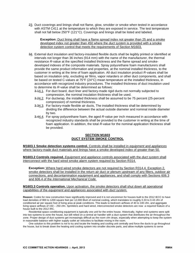
23. Duct coverings and linings shall not flame, glow, smolder or smoke when tested in accordance with ASTM C411 at the temperature to which they are exposed in service. The test temperature shall not fall below 250°F (121°C). Coverings and linings shall be listed and labeled.
Exception: Duct lining shall have a flame spread index not greater than 25 and a smoke developed index not greater than 450 where the duct system is provided with a smoke detection system control that meets the requirements of Section M1603.
34. External duct insulation and factory-insulated flexible ducts shall be legibly printed or identified at
intervals not longer than 36 inches (914 mm) with the name of the manufacturer, the thermal resistance R-value at the specified installed thickness and the flame spread and smoke-developed indexes of the composite materials. Spray polyurethane foam manufacturers shall provide the same product information and properties, at the nominal installed thickness, to the customer in writing at the time of foam application. All duct insulation product R-values shall be based on insulation only, excluding air films, vapor retarders or other duct components, and shall be based on tested C-values at 75°F (24°C) mean temperature at the installed thickness, in accordance with recognized industry procedures. The installed thickness of duct insulation used to determine its R-value shall be determined as follows: 3.14.1. For duct board, duct liner and factory-made rigid ducts not normally subjected to
compression, the nominal insulation thickness shall be used. 3.24.2. For ductwrap, the installed thickness shall be assumed to be 75 percent (25-percent
compression) of nominal thickness. 3.34.3. For factory-made flexible air ducts, The installed thickness shall be determined by
dividing the difference between the actual outside diameter and nominal inside diameter by two.
3.44.4. For spray polyurethane foam, the aged R-value per inch measured in accordance with recognized industry standards shall be provided to the customer in writing at the time of foam application. In addition, the total R-value for the nominal application thickness shall be provided.
SECTION M1603
DUCT SYSTEM SMOKE CONTROL
M1603.1 Smoke detection systems control. Controls shall be installed in equipment and appliances where factory-made duct materials and linings have a smoke developed index of greater than 50. M1603.2 Controls required. Equipment and appliance controls associated with the duct system shall interconnect with the hard wired smoke alarm system required by Section R314.
Exception: Where hard wired smoke detectors are not required by Section R314.4, Exception 2, smoke detectors shall be installed in the return air duct or plenum upstream of any filters, outdoor air connections, and decontamination equipment and appliances, and shall comply with Sections 606.3 and 606.4 of the International Mechanical Code.
M1603.3 Controls operation. Upon activation, the smoke detectors shall shut down all operational capabilities of the equipment and appliances associated with duct system. Reason: Codes for new construction have significantly improved and it is not uncommon for houses built to the 2012 IECC to have load densities of 900 to 1200 square feet per 12,000 Btuh of nominal cooling, which translates to roughly 0.33 to 0.44 cfm of conditioned air per square foot of living area at peak conditions. This leads to bedroom airflows of 40 to 100 cfm, and aggregate living space airflows of 150 – 250 cfm. Sprinklers and hard wired, interconnected smoke detectors are now a required feature of a house built to the 2012 IRC.
Residential space conditioning equipment is typically one unit for the entire house. Historically, higher end systems were split into two systems to zone the house, but still relied on a central air handler with a duct system that distributes the air throughout the zone. Proper design of duct systems get increasingly difficult as the room cfm drops, especially when attempting to keep the system in reasonable balance with higher supply outlet air velocities to facilitate mixing in the room.
One solution to this problem is not to try and locate the heating and cooling unit centrally and force the ducts to go throughout the house, but to break down the heating and cooling system into smaller discrete parts, and allow multiple systems to serve
ICC COMMITTEE ACTION HEARINGS ::: April, 2013 RM64
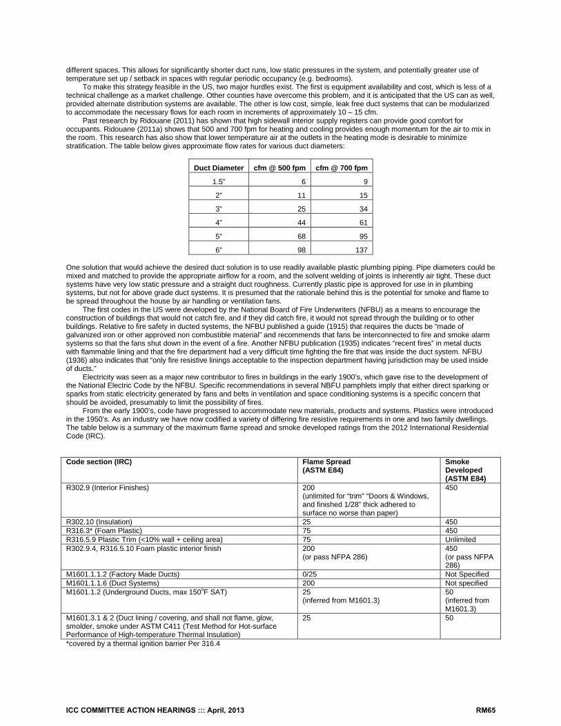
different spaces. This allows for significantly shorter duct runs, low static pressures in the system, and potentially greater use of temperature set up / setback in spaces with regular periodic occupancy (e.g. bedrooms).
To make this strategy feasible in the US, two major hurdles exist. The first is equipment availability and cost, which is less of a technical challenge as a market challenge. Other counties have overcome this problem, and it is anticipated that the US can as well, provided alternate distribution systems are available. The other is low cost, simple, leak free duct systems that can be modularized to accommodate the necessary flows for each room in increments of approximately 10 – 15 cfm.
Past research by Ridouane (2011) has shown that high sidewall interior supply registers can provide good comfort for occupants. Ridouane (2011a) shows that 500 and 700 fpm for heating and cooling provides enough momentum for the air to mix in the room. This research has also show that lower temperature air at the outlets in the heating mode is desirable to minimize stratification. The table below gives approximate flow rates for various duct diameters:
Duct Diameter cfm @ 500 fpm cfm @ 700 fpm
1.5” 6 9
2” 11 15
3” 25 34
4” 44 61
5” 68 95
6” 98 137 One solution that would achieve the desired duct solution is to use readily available plastic plumbing piping. Pipe diameters could be mixed and matched to provide the appropriate airflow for a room, and the solvent welding of joints is inherently air tight. These duct systems have very low static pressure and a straight duct roughness. Currently plastic pipe is approved for use in in plumbing systems, but not for above grade duct systems. It is presumed that the rationale behind this is the potential for smoke and flame to be spread throughout the house by air handling or ventilation fans.
The first codes in the US were developed by the National Board of Fire Underwriters (NFBU) as a means to encourage the construction of buildings that would not catch fire, and if they did catch fire, it would not spread through the building or to other buildings. Relative to fire safety in ducted systems, the NFBU published a guide (1915) that requires the ducts be “made of galvanized iron or other approved non combustible material” and recommends that fans be interconnected to fire and smoke alarm systems so that the fans shut down in the event of a fire. Another NFBU publication (1935) indicates “recent fires” in metal ducts with flammable lining and that the fire department had a very difficult time fighting the fire that was inside the duct system. NFBU (1936) also indicates that “only fire resistive linings acceptable to the inspection department having jurisdiction may be used inside of ducts.”
Electricity was seen as a major new contributor to fires in buildings in the early 1900’s, which gave rise to the development of the National Electric Code by the NFBU. Specific recommendations in several NBFU pamphlets imply that either direct sparking or sparks from static electricity generated by fans and belts in ventilation and space conditioning systems is a specific concern that should be avoided, presumably to limit the possibility of fires.
From the early 1900’s, code have progressed to accommodate new materials, products and systems. Plastics were introduced in the 1950’s. As an industry we have now codified a variety of differing fire resistive requirements in one and two family dwellings. The table below is a summary of the maximum flame spread and smoke developed ratings from the 2012 International Residential Code (IRC).
Code section (IRC) Flame Spread (ASTM E84)
Smoke Developed (ASTM E84)
R302.9 (Interior Finishes) 200 (unlimited for “trim” “Doors & Windows, and finished 1/28” thick adhered to surface no worse than paper)
450
R302.10 (Insulation) 25 450 R316.3* (Foam Plastic) 75 450 R316.5.9 Plastic Trim (<10% wall + ceiling area) 75 Unlimited R302.9.4, R316.5.10 Foam plastic interior finish 200
(or pass NFPA 286) 450 (or pass NFPA 286)
M1601.1.1.2 (Factory Made Ducts) 0/25 Not Specified M1601.1.1.6 (Duct Systems) 200 Not specified M1601.1.2 (Underground Ducts, max 150oF SAT) 25
(inferred from M1601.3) 50 (inferred from M1601.3)
M1601.3.1 & 2 (Duct lining / covering, and shall not flame, glow, smolder, smoke under ASTM C411 (Test Method for Hot-surface Performance of High-temperature Thermal Insulation)
25
50
*covered by a thermal ignition barrier Per 316.4
ICC COMMITTEE ACTION HEARINGS ::: April, 2013 RM65
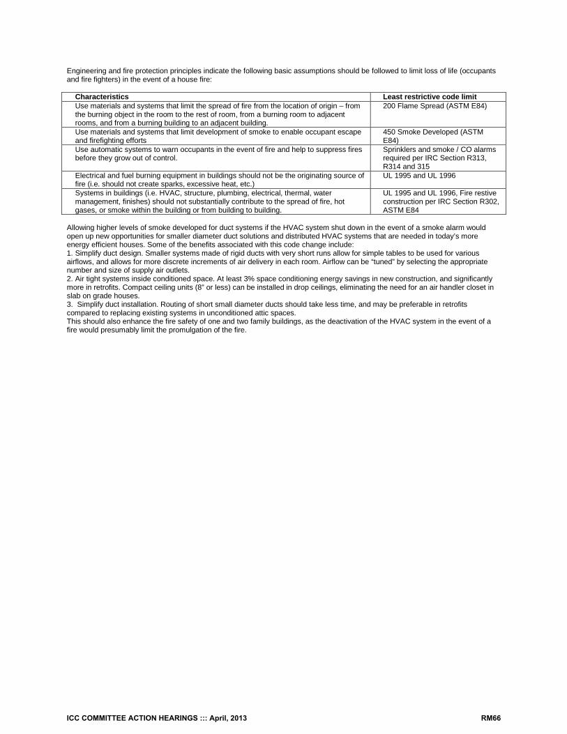
Engineering and fire protection principles indicate the following basic assumptions should be followed to limit loss of life (occupants and fire fighters) in the event of a house fire:
Characteristics Least restrictive code limit Use materials and systems that limit the spread of fire from the location of origin – from the burning object in the room to the rest of room, from a burning room to adjacent rooms, and from a burning building to an adjacent building.
200 Flame Spread (ASTM E84)
Use materials and systems that limit development of smoke to enable occupant escape and firefighting efforts
450 Smoke Developed (ASTM E84)
Use automatic systems to warn occupants in the event of fire and help to suppress fires before they grow out of control.
Sprinklers and smoke / CO alarms required per IRC Section R313, R314 and 315
Electrical and fuel burning equipment in buildings should not be the originating source of fire (i.e. should not create sparks, excessive heat, etc.)
UL 1995 and UL 1996
Systems in buildings (i.e. HVAC, structure, plumbing, electrical, thermal, water management, finishes) should not substantially contribute to the spread of fire, hot gases, or smoke within the building or from building to building.
UL 1995 and UL 1996, Fire restive construction per IRC Section R302, ASTM E84
Allowing higher levels of smoke developed for duct systems if the HVAC system shut down in the event of a smoke alarm would open up new opportunities for smaller diameter duct solutions and distributed HVAC systems that are needed in today’s more energy efficient houses. Some of the benefits associated with this code change include: 1. Simplify duct design. Smaller systems made of rigid ducts with very short runs allow for simple tables to be used for various airflows, and allows for more discrete increments of air delivery in each room. Airflow can be “tuned” by selecting the appropriate number and size of supply air outlets. 2. Air tight systems inside conditioned space. At least 3% space conditioning energy savings in new construction, and significantly more in retrofits. Compact ceiling units (8” or less) can be installed in drop ceilings, eliminating the need for an air handler closet in slab on grade houses. 3. Simplify duct installation. Routing of short small diameter ducts should take less time, and may be preferable in retrofits compared to replacing existing systems in unconditioned attic spaces. This should also enhance the fire safety of one and two family buildings, as the deactivation of the HVAC system in the event of a fire would presumably limit the promulgation of the fire.
ICC COMMITTEE ACTION HEARINGS ::: April, 2013 RM66
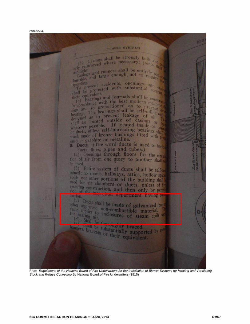
Citations:
From Regulations of the National Board of Fire Underwriters for the Installation of Blower Systems for Heating and Ventilating, Stock and Refuse Conveying By National Board of Fire Underwriters (1915)
ICC COMMITTEE ACTION HEARINGS ::: April, 2013 RM67
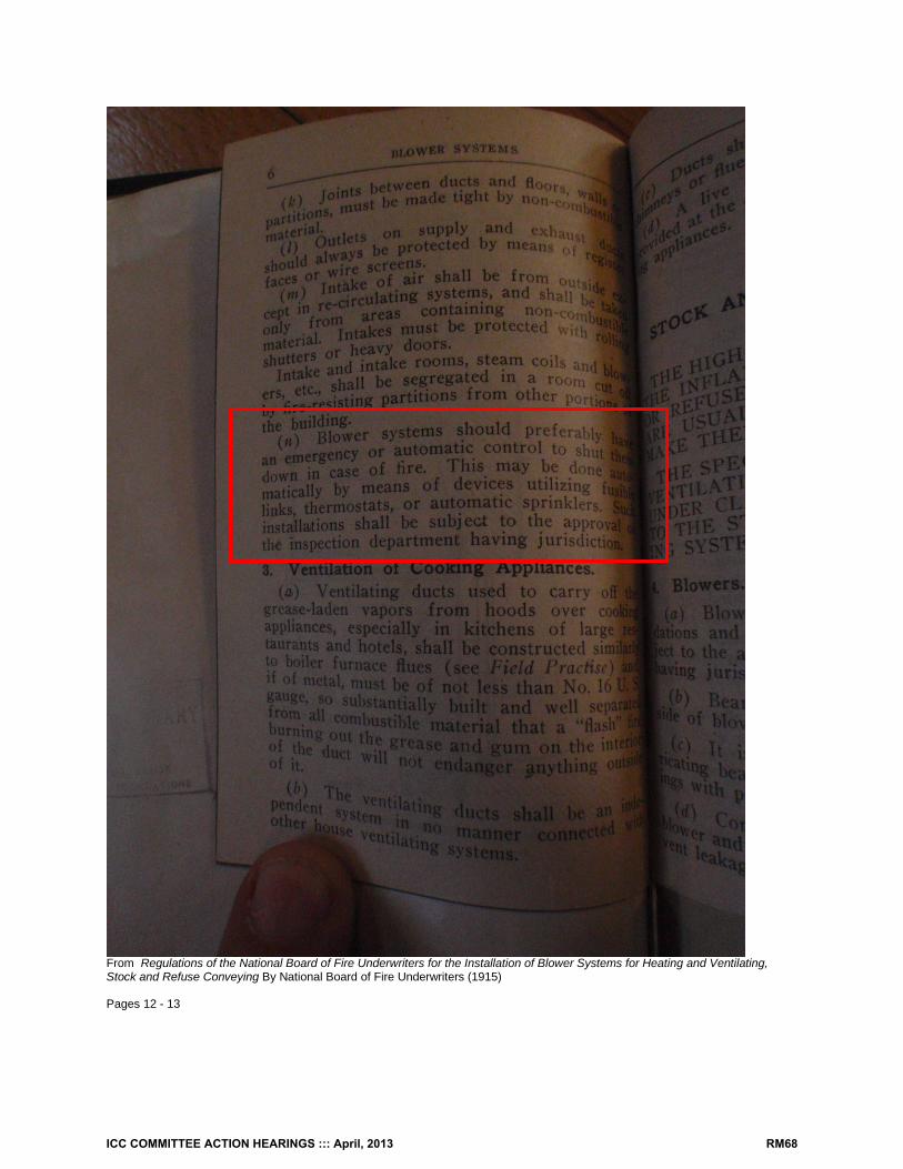
From Regulations of the National Board of Fire Underwriters for the Installation of Blower Systems for Heating and Ventilating, Stock and Refuse Conveying By National Board of Fire Underwriters (1915) Pages 12 - 13
ICC COMMITTEE ACTION HEARINGS ::: April, 2013 RM68
From Ventilating and Air Conditioning Systems Employing Ducts, New York; National Board of Fire Underwriters. (1935)
ICC COMMITTEE ACTION HEARINGS ::: April, 2013 RM69
From Ventilating and Air Conditioning Systems Employing Ducts, New York; National Board of Fire Underwriters. (1935)
ICC COMMITTEE ACTION HEARINGS ::: April, 2013 RM70
From Ventilating and Air Conditioning Systems Employing Ducts, New York; National Board of Fire Underwriters. (1935)
ICC COMMITTEE ACTION HEARINGS ::: April, 2013 RM71
From Ventilating and Air Conditioning Systems Employing Ducts, New York; National Board of Fire Underwriters. (1935)
ICC COMMITTEE ACTION HEARINGS ::: April, 2013 RM72
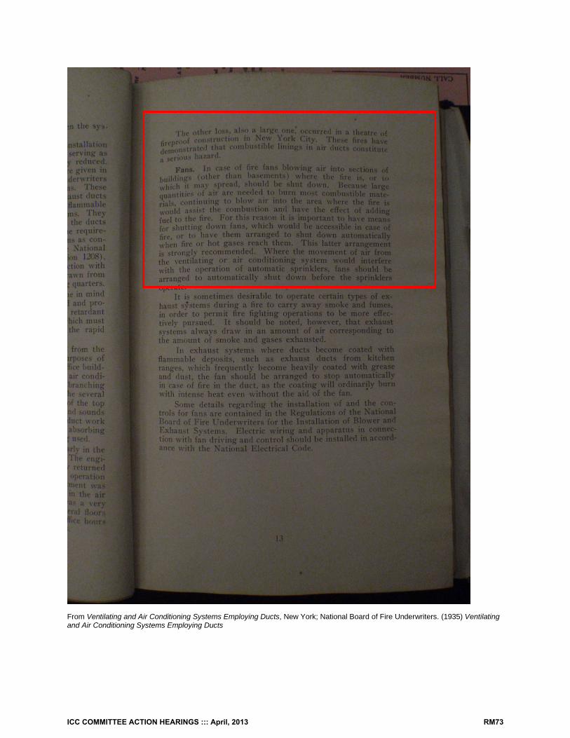
From Ventilating and Air Conditioning Systems Employing Ducts, New York; National Board of Fire Underwriters. (1935) Ventilating and Air Conditioning Systems Employing Ducts
ICC COMMITTEE ACTION HEARINGS ::: April, 2013 RM73
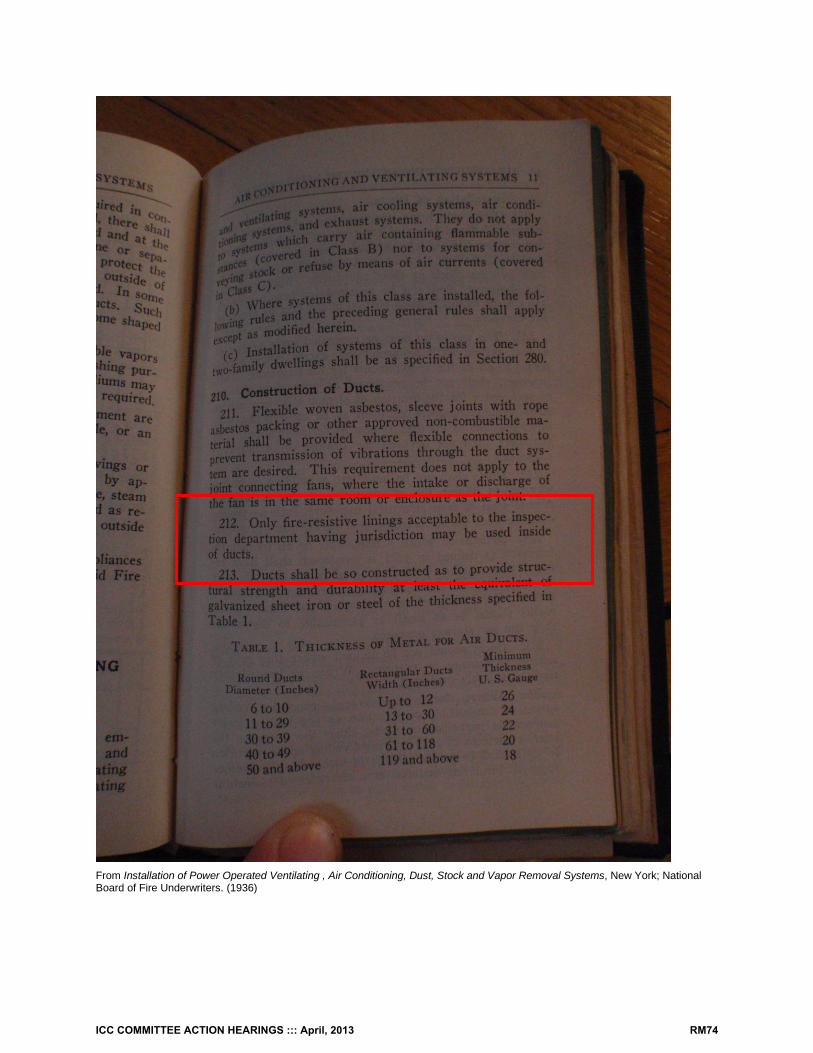
From Installation of Power Operated Ventilating , Air Conditioning, Dust, Stock and Vapor Removal Systems, New York; National Board of Fire Underwriters. (1936)
ICC COMMITTEE ACTION HEARINGS ::: April, 2013 RM74
Attached PDF files: Ridouane. El Hassan and Gawlik. Keith. Prediction of Air Mixing from High Sidewall Diffusers in Cooling Mode Preprint Presented at the ASHRAE Winter Conference Las Vegas, Nevada January 29 – February 2, 2011 Conference Paper NREL/CP-5500-49010 February 2011 Web address: www.nrel.gov/docs/fy11osti/49010.pdf, accessed 01/03/2012 Ridouane, El Hassan. Numerical Evaluation of Indoor Air Distribution in High Performance Homes Ph.D. National Renewable Energy Laboratory Residential Building Energy Efficiency Meeting 2010 July 21, 2010 Web address: http://apps1.eere.energy.gov/buildings/publications/pdfs/building_america/ns/b23_indoor_air_distr.pdf, accessed 01/03/2012
Cost Impact: The code change proposal will not increase the cost of construction. RM49-13 Public Hearing: Committee: AS AM D Assembly: ASF AMF DF
M1601.1.1-RM-PRAHL.DOC
ICC COMMITTEE ACTION HEARINGS ::: April, 2013 RM75
RM50 – 13 M1601.1.1 Proponent: Dustin McLehaney, Chesterfield County, VA, representing Va. Plumbing and Mechanical Inspectors Association (VPMIA) And Va. Building Code Officials Association (VBCOA) ([email protected]) Revise as follows: M1601.1.1 Above-ground duct systems. Above-ground duct systems shall conform to the following:
1. Equipment connected to duct systems shall be designed to limit discharge air temperature to a
maximum of 250ºF (121ºC). 2. Factory-made air ducts shall be constructed of Class 0 or Class 1 materials as designated in
Table M1601.1.1(1). 3. Fibrous duct construction shall conform to the SMACNA Fibrous Glass Duct Construction
Standards or NAIMA Fibrous Glass Duct Construction Standards . 4. Minimum thickness of metal duct material shall be as listed in Table M1601.1.1(2). Galvanized
steel shall conform to ASTM A 653. 5. Use of gypsum products to construct return air ducts or plenums is permitted, provided that the
air temperature does not exceed 125°F (52°C) and exposed surfaces are not subject to condensation.
6. Duct systems shall be constructed of materials having a flame spread index not greater than 200. 7. Stud wall cavities and the spaces between solid floor joists to be used as air plenums shall
comply with the following conditions: 7.1. These cavities or spaces shall not be used as a plenum for supply air. 7.2. These cavities or spaces shall not be part of a required fire-resistance-rated assembly. 7.3. Stud wall cavities shall not convey air from more than one floor level. 7.4. Stud wall cavities and joist-space plenums shall be isolated from adjacent concealed
spaces by tight-fitting fire blocking in accordance with Section R602.8. 7.5. Stud wall cavities in the outside walls of building envelope assemblies shall not be
utilized as air plenums. 7. Building framing cavities shall not be used as ducts or plenums.
Reason: IECC R403.2.3 and IRC N1103.2.3 prohibit the use of building cavities as ducts or plenums. This will ensure consistency between internal IRC sections and between the IRC and the IECC. Cost Impact: None RM50-13 Public Hearing: Committee: AS AM D Assembly: ASF AMF DF
M1601.1.1.1-RM-MCLEHANEY.DOC
ICC COMMITTEE ACTION HEARINGS ::: April, 2013 RM76
RM51 – 13 R202, M1601.3, Chapter 44 Proponent: Vickie Lovell, InterCode Incorporated, representing the Reflective Insulation Manufacturers Association International ([email protected]) Add new definition as follows:
SECTION R202 DEFINITIONS
REFLECTIVE DUCT INSULATION. A thermal insulation assembly consisting of one or more surfaces that have an emittance of 0.1 or less, and that bound an enclosed air space or spaces. Revise as follows:
SECTION M1601 DUCT CONSTRUCTION
M1601.3 Duct insulation materials. Duct insulation materials shall conform to the following requirements:
1. Duct coverings and linings, including adhesives where used, shall have a flame spread index not higher than 25, and a smoke-developed index not over 50 when tested in accordance with ASTM E 84 or UL 723, using the specimen preparation and mounting procedures of ASTM E 2231.
Exception: Spray application of polyurethane foam to the exterior of ducts in attics and crawl spaces shall be permitted subject to all of the following:
1. The flame spread index is not greater than 25 and the smoke-developed index is not greater than 450 at the specified installed thickness.
2. The foam plastic is protected in accordance with the ignition barrier requirements of Sections R316.5.3 and R316.5.4.
3. The foam plastic complies with the requirements of Section R316.
2. Duct coverings and linings shall not flame, glow, smolder or smoke when tested in accordance with ASTM C 411 at the temperature to which they are exposed in service. The test temperature shall not fall below 250°F (121°C). Coverings and linings shall be listed and labeled.
3. External reflective duct insulation shall be legibly printed or identified at intervals not greater than 36 inches (914 mm) with the name of the manufacturer, the product R-value at the specified installed thickness and the flame spread and smoke-developed indices. The installed thickness of the external duct insulation shall include the enclosed air space(s). The product R-value for external reflective duct insulation shall be determined in accordance with ASTM C1668.
43. External duct insulation and factory-insulated flexible ducts shall be legibly printed or identified at intervals not longer than 36 inches (914 mm) with the name of the manufacturer, the thermal resistance R-value at the specified installed thickness and the flame spread and smoke-developed indexes of the composite materials. Spray polyurethane foam manufacturers shall provide the same product information and properties, at the nominal installed thickness, to the customer in writing at the time of foam application. All non-reflective duct insulation product R-values shall be based on insulation only, excluding air films, vapor retarders or other duct components, and shall be based on tested C-values at 75°F (24°C) mean temperature at the installed thickness, in accordance with recognized industry procedures. The installed thickness of duct insulation used to determine its R-value shall be determined as follows: 4.1 3.1. For duct board, duct liner and factory-made rigid ducts not normally subjected to
compression, the nominal insulation thickness shall be used.
ICC COMMITTEE ACTION HEARINGS ::: April, 2013 RM77
4.2 3.2. For ductwrap, the installed thickness shall be assumed to be 75 percent (25-percent compression) of nominal thickness.
4.3 3.3. For factory-made flexible air ducts, the installed thickness shall be determined by dividing the difference between the actual outside diameter and nominal inside diameter by two.
4.4 3.4. For spray polyurethane foam, the aged R-value per inch measured in accordance with recognized industry standards shall be provided to the customer in writing at the time of foam application. In addition, the total R-value for the nominal application thickness shall be provided.
Add new standard to Chapter 44 as follows: ASTM C1668-12 Standard Specification for Externally Applied Reflective Insulation Systems on Rigid Duct in Heating, Ventilation, and Air Conditioning (HVAC) Systems Reason: The goal of this proposal is to define an existing commonly installed insulation that should be properly included in the ICC Codes. This proposal will provide clear requirements for a duct insulation that has been in the market for many years and has nationwide distribution and installation. This proposal includes the specific requirements for reflective duct insulation.
This proposal improves the codes by providing installers and officials with a clear path on the specifications that pertain to this product, the appropriate definitions and an ASTM reference.
Reflective duct insulation is a well-established type of material/system and it has an ASTM standard specification, namely ASTM C1668 Standard Specification for Externally Applied Reflective Insulation Systems on Rigid Duct in Heating, Ventilation, and Air Conditioning (HVAC) Systems. This standard can be viewed at: http://reflectixinc.com/literature/securedpdfs/C1668.pdf
It is the intent of this proposal to provide installers and officials with specific requirements and definitions as they pertain to reflective duct insulation products. Cost Impact: This proposal will not increase the cost of construction. Analysis: A review of the standard proposed for inclusion in the code, [ASTM C1668-12] with regard to the ICC criteria for referenced standards (Section 3.6 of CP#28) will be posted on the ICC website on or before April 1, 2013. RM51-13 Public Hearing: Committee: AS AM D Assembly: ASF AMF DF
M1601.3-RM-LOVELL.DOC
ICC COMMITTEE ACTION HEARINGS ::: April, 2013 RM78
RM52 – 13 M1601.4.1 Proponent: David Hall CFM, Georgetown Texas representing the ICC PMG Code Action Committee ([email protected]) Revise as follows: M1601.4.1 Joints, seams and connections. All longitudinal and transverse joints, seams and connections in metallic and nonmetallic ducts shall be constructed as specified in SMACNA HVAC Duct Construction Standards—Metal and Flexible and NAIMA Fibrous Glass Duct Construction Standards. All joints, longitudinal and transverse seams, and connections in ductwork shall be securely fastened and sealed with welds, gaskets, mastics (adhesives), mastic-plus-embedded-fabric systems, liquid sealants or tapes. Tapes and mastics used to seal fibrous glass ductwork shall be listed and labeled in accordance with UL 181A and shall be marked "181A-P" for pressure-sensitive tape, "181 A-M" for mastic or "181 A-H" for heat-sensitive tape. Closure systems Tapes and mastics used to seal metallic and flexible air ducts and flexible air connectors shall comply with UL 181B and shall be marked “181 B-FX” for pressure sensitive tape or “181 BM” for mastic. Duct connections to flanges of air distribution system equipment shall be sealed and mechanically fastened. Mechanical fasteners for use with flexible nonmetallic air ducts shall comply with UL 181B and shall be marked 181B-C. Crimp joints for round metallic ducts shall have a contact lap of not less than 1 inch (25.4 mm) and shall be mechanically fastened by means of not less than three sheet-metal screws or rivets equally spaced around the joint. Closure systems used to seal metal all ductwork shall be installed in accordance with the manufacturers’ instructions. Round metallic ducts shall be mechanically fastened by means of at least three sheet metal screws or rivets spaced equally around the joint. Unlisted duct tape shall not be permitted as a sealant on any duct.
Exceptions:
1. Spray polyurethane foam shall be permitted to be applied without additional joint seals. 2. Where a duct connection is made that is partially inaccessible, three screws or rivets shall be
equally spaced on the exposed portion of the joint so as to prevent a hinge effect. 3. Continuously welded and locking type longitudinal joints and seams in ducts operating at
static pressures less than 2 inches of water column (500 Pa) pressure classification shall not require additional closure systems.
Reason: This proposal simplifies this section by stating what is meant by “closure systems.” Tapes and mastics are addressed in UL181A. There is no closure system listed specifically for metal ducts, but it is appropriate to require sealing products used for metal ducts to be listed to UL181A because if the sealing product is good enough for fibrous glass ducts it is good enough for metal ducts. This is the case in the field, as fibrous glass duct tapes are commonly used with metal ducts. The manufacturer’s instructions should apply for all closure systems, not just those for metal ducts. The last sentence is unnecessary because this proposal requires all tapes to be listed, including those used with metal ducts.
This proposal is submitted by the ICC Plumbing, Mechanical and Fuel Gas Code Action Committee (PMGCAC). The PMGCAC was established by the ICC Board of Directors to pursue opportunities to improve and enhance an assigned International Code or portion thereof. This includes both the technical aspects of the codes as well as the code content in terms of scope and application of referenced standards. Since its inception in July, 2011, the PMGCAC has held 2 open meetings, multiple conference calls and multiple workgroup calls which included members of the PMGCAC. Interested parties also participated in all of the meetings and conference calls to discuss and debate the proposed changes. Cost Impact: The code change proposal will not increase the cost of construction. RM52-13 Public Hearing: Committee: AS AM D Assembly: ASF AMF DF
M1601.4#1-RM-HALL-PMGCAC.DOC
ICC COMMITTEE ACTION HEARINGS ::: April, 2013 RM79
RM53 – 13 M1601.4.1 Proponent: David Hall CFM, Georgetown Texas representing the ICC PMG Code Action Committee ([email protected]); Vickie Lovell, InterCode Inc., representing DuctMate Industries ([email protected]) Revise as follows: M1601.4.1 Joints, seams and connections. All longitudal and transverse joints, seams and connections in metallic and nonmetallic ducts shall be constructed as specified in SMACNA HVAC Duct Construction Standards—Metal and Flexible and NAIMA Fibrous Glass Duct Construction Standards. All joints, longitudinal and transverse seams, and connections in ductwork shall be securely fastened and sealed with welds, gaskets, mastics (adhesives), mastic-plus-embedded-fabric systems or tapes. Closure systems used to seal flexible air ducts and flexible air connectors shall comply with UL 181B and shall be marked “181 B-FX” for pressure sensitive tape or “181 BM” for mastic. Duct connections to flanges of air distribution system equipment shall be sealed and mechanically fastened. Mechanical fasteners for use with flexible nonmetallic air ducts shall comply with UL 181B and shall be marked 181B-C. Crimp joints for round metallic ducts shall have a contact lap of not less than 1 inch (25.4 mm) and shall be mechanically fastened by means of not less than three sheet-metal screws or rivets equally spaced around the joint. Closure systems used to seal metal ductwork shall be installed in accordance with the manufacturers’ instructions. Round metallic ducts shall be mechanically fastened by means of at least three sheet metal screws or rivets spaced equally around the joint. Unlisted duct tape shall not be permitted as a sealant on any duct.
Exceptions:
1. Spray polyurethane foam shall be permitted to be applied without additional joint seals. 2. Where a duct connection is made that is partially inaccessible, three screws or rivets shall be
equally spaced on the exposed portion of the joint so as to prevent a hinge effect. 3. Continuously welded and locking type longitudinal joints and seams in ducts operating at
static pressures less than 2 inches of water column (500 Pa) pressure classification shall not require additional closure systems. For ducts having a static pressure classification of less than 2 inches of water column (500Pa), additional closure systems shall not be required for continuously welded joints and seams and locking-type joints and seams of other than the snap-lock and button-lock types.
Reason: (Hall-PMGCAC): Unless sealant or a gasket is used, snap-lock and button-lock type seams will leak significantly. The current exception attempted to prevent unnecessary sealing for joints and seams that leak very little or not at all, but it went too far by including all locking type joints and seams. Some locking joints are leakproof such as mechanically folded seams used for spiral seam duct, but this cannot be said for all locking joints. This text was approved for the 2015 IMC.
This proposal is submitted by the ICC Plumbing, Mechanical and Fuel Gas Code Action Committee (PMGCAC). The PMGCAC was established by the ICC Board of Directors to pursue opportunities to improve and enhance an assigned International Code or portion thereof. This includes both the technical aspects of the codes as well as the code content in terms of scope and application of referenced standards. Since its inception in July, 2011, the PMGCAC has held 2 open meetings, multiple conference calls and multiple workgroup calls which included members of the PMGCAC. Interested parties also participated in all of the meetings and conference calls to discuss and debate the proposed changes. Lovell): This proposed text is derived from a revision to the International Mechanical Code that was proposed by the PMG Code Action Committee in M151-12 and was approved by the voting membership in Portland for the 2015 IMC. That reason statement is supplied below:
Unless sealant or a gasket is used, snap-lock and button-lock type seams will leak significantly. The current exception attempted to prevent unnecessary sealing for joints and seams that leak very little or not at all, but it went too far by including all locking type joints and seams. Some locking joints are leakproof such as mechanically folded seams used for spiral seam duct, but this cannot be said for all locking joints.
The identical proposal that was approved As Submitted in the Mechanical Code hearings in Portland is being submitted to the 2015 IECC residential requirements for consistency.
ICC COMMITTEE ACTION HEARINGS ::: April, 2013 RM80
Cost Impact: (Hall-PMGCAC): The code change proposal will not increase the cost of construction. (Lovell): This proposal reduces the cost of installation. RM53-13 Public Hearing: Committee: AS AM D Assembly: ASF AMF DF
M1601.4.1 #2-RM-HALL-LOVELL-PMGCAC
ICC COMMITTEE ACTION HEARINGS ::: April, 2013 RM81
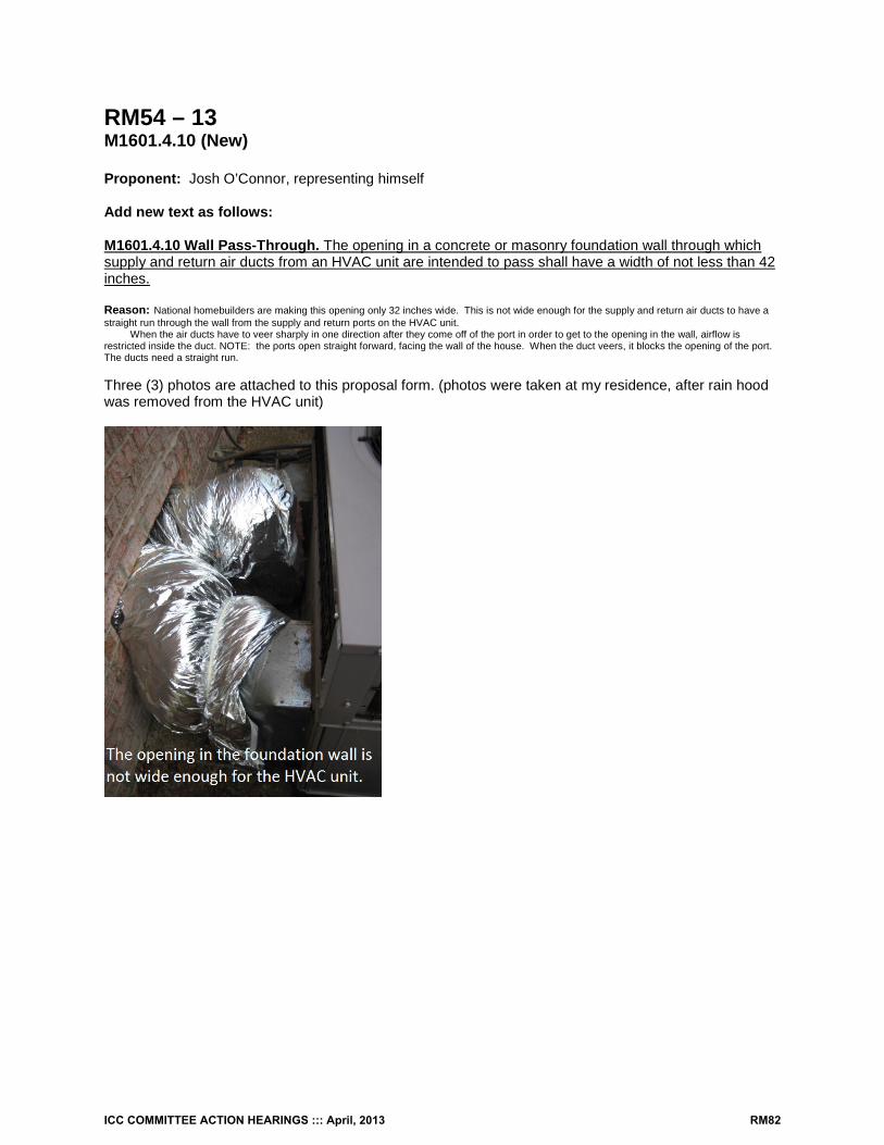
RM54 – 13 M1601.4.10 (New) Proponent: Josh O’Connor, representing himself Add new text as follows: M1601.4.10 Wall Pass-Through. The opening in a concrete or masonry foundation wall through which supply and return air ducts from an HVAC unit are intended to pass shall have a width of not less than 42 inches. Reason: National homebuilders are making this opening only 32 inches wide. This is not wide enough for the supply and return air ducts to have a straight run through the wall from the supply and return ports on the HVAC unit.
When the air ducts have to veer sharply in one direction after they come off of the port in order to get to the opening in the wall, airflow is restricted inside the duct. NOTE: the ports open straight forward, facing the wall of the house. When the duct veers, it blocks the opening of the port. The ducts need a straight run. Three (3) photos are attached to this proposal form. (photos were taken at my residence, after rain hood was removed from the HVAC unit)
ICC COMMITTEE ACTION HEARINGS ::: April, 2013 RM82
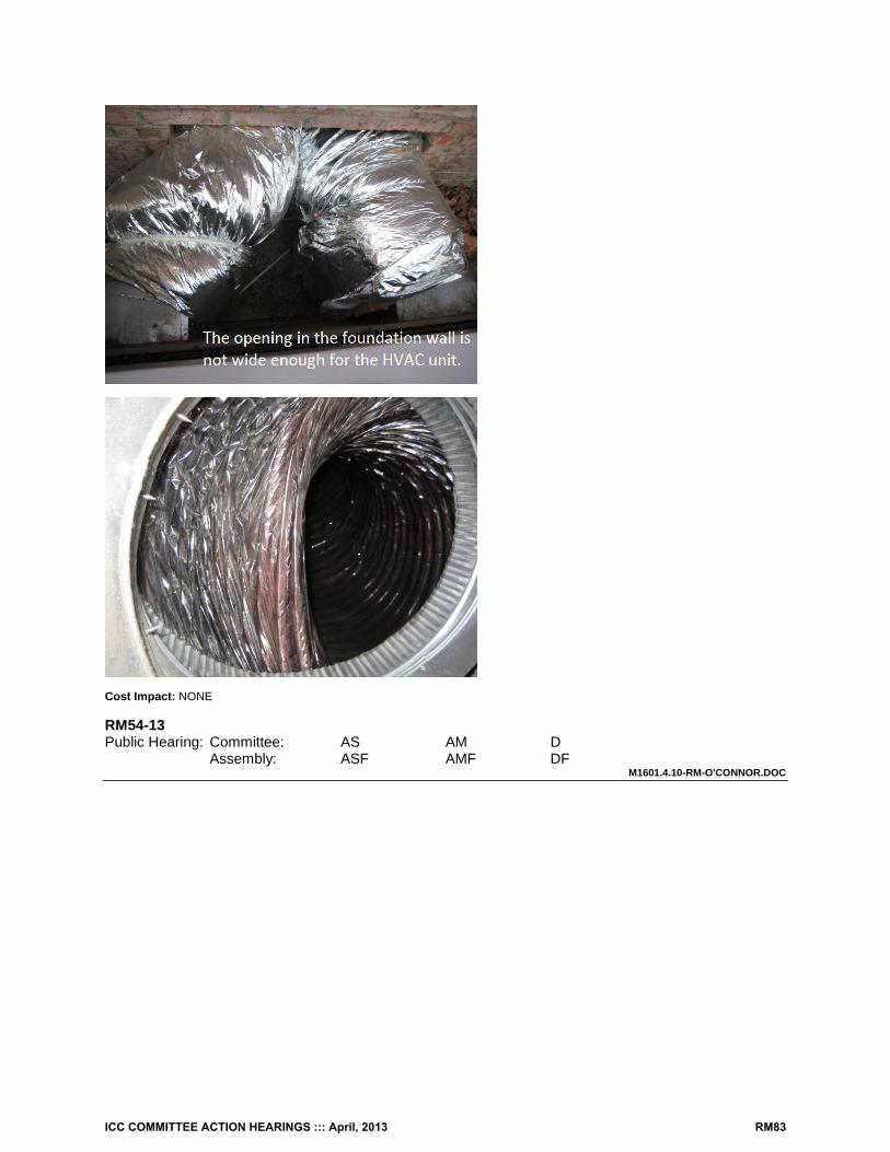
Cost Impact: NONE RM54-13 Public Hearing: Committee: AS AM D Assembly: ASF AMF DF
M1601.4.10-RM-O'CONNOR.DOC
ICC COMMITTEE ACTION HEARINGS ::: April, 2013 RM83
RM55 – 13 M1601.4.2 (New) Proponent: David Hall CFM, Georgetown Texas representing the ICC PMG Code Action Committee ([email protected]) Add new text as follows: M1601.4.2 Duct lap. Crimp joints for round and oval metal ducts shall be lapped not less than one inch and the male end of the duct shall extend into the adjoining duct in the direction of airflow. Reason: Section M1601.4.1 states the number of fasteners to be used for the fastening of metal ducts but is silent on the direction of the lap relative to airflow. The current code is also silent on oval ducts which are commonly installed in dwellings. The code should specifically state how much lap there must be for round and oval ducts prior to securing them as stated in Section M1601.4.1.
This proposal is submitted by the ICC Plumbing, Mechanical and Fuel Gas Code Action Committee (PMGCAC). The PMGCAC was established by the ICC Board of Directors to pursue opportunities to improve and enhance an assigned International Code or portion thereof. This includes both the technical aspects of the codes as well as the code content in terms of scope and application of referenced standards. Since its inception in July, 2011, the PMGCAC has held 2 open meetings, multiple conference calls and multiple workgroup calls which included members of the PMGCAC. Interested parties also participated in all of the meetings and conference calls to discuss and debate the proposed changes. Cost Impact: The code change proposal will not increase the cost of construction. . RM55-13 Public Hearing: Committee: AS AM D Assembly: ASF AMF DF
M1601.4.2 (NEW)-RM-HALL-PMGCAC
ICC COMMITTEE ACTION HEARINGS ::: April, 2013 RM84
RM56 – 13 M1601.4.3 Proponent: David Hall CFM, Georgetown Texas representing the ICC PMG Code Action Committee ([email protected]) Revise as follows: M1601.4.3 Support. Metal ducts shall be supported by 1/2-inch (13 mm) wide 18-gage metal straps or 12-gage galvanized wire at intervals not exceeding 10 feet (3048 mm) or other approved means. Nonmetallic ducts shall be supported in accordance with the manufacturer’s installation instructions. Ducts shall be supported in accordance with SMACNA HVAC Duct Construction Standards—Metal and Flexible. Reason: This section should just reference the SMACNA standards as opposed to specifying a support interval. The 10 foot interval requirement is too broad and is inappropriate for many sizes and types of ducts . Many ducts require closer supports. This text could be easily interpreted as allowing 10 feet maximum support intervals for all ducts. This section is not being enforced since nobody installs 18 gage metal straps to support residential ducts.
This proposal is submitted by the ICC Plumbing, Mechanical and Fuel Gas Code Action Committee (PMGCAC). The PMGCAC was established by the ICC Board of Directors to pursue opportunities to improve and enhance an assigned International Code or portion thereof. This includes both the technical aspects of the codes as well as the code content in terms of scope and application of referenced standards. Since its inception in July, 2011, the PMGCAC has held 2 open meetings, multiple conference calls and multiple workgroup calls which included members of the PMGCAC. Interested parties also participated in all of the meetings and conference calls to discuss and debate the proposed changes. Cost Impact: The code change proposal will increase the cost of construction. . RM56-13 Public Hearing: Committee: AS AM D Assembly: ASF AMF DF
M1601.4.3-RM-HALL-PMGCAC
ICC COMMITTEE ACTION HEARINGS ::: April, 2013 RM85
RM57 – 13 M1602 Proponent: Guy McMann MCP, Jefferson County Colorado representing Colorado Association of Plumbing and Mechanical Officials (CAPMO) Revise as follows: M1602.1 Return air Return air shall be taken from inside the dwelling . Dilution of return air with outdoor air shall be permitted. M1602.2 Prohibited sources. Outdoor and return air for a forced-air heating or cooling system shall not be taken from the following locations:
1. Closer than 10 feet (3048 mm) to an appliance vent outlet, a vent opening from a plumbing drainage system or the discharge outlet of an exhaust fan, unless the outlet is 3 feet (914 mm) above the outside air inlet.
2. Where flammable vapors are present; or where located less than 10 feet (3048 mm) above the surface of any abutting public way or driveway; or where located at grade level by a sidewalk, street, alley or driveway.
3. A room or space, the volume of which is less than 25 percent of the entire volume served by the system. Where connected by a permanent opening having an area sized in accordance with ACCA Manual D, adjoining rooms or spaces shall be considered as a single room or space for the purpose of determining the volume of the rooms or spaces.
Exception: The minimum volume requirement shall not apply where the amount of return air taken from a room or space is less than or equal to the amount of supply air delivered to the room or space.
4. A closet, bathroom, toilet room, kitchen, garage, mechanical room, boiler room, furnace room,
unconditioned attic or other dwelling unit .
Exception: Dedicated forced-air systems serving only a garage shall not be prohibited from obtaining return air from the garage.
5. A room or space containing a fuel-burning appliance where such room or space serves as the
sole source of return air.
Exceptions:
1. The fuel-burning appliance is a direct-vent appliance or an appliance not requiring a vent in accordance with Section M1801.1 or Chapter 24.
2. The room or space complies with the following requirements: 2.1. The return air shall be taken from a room or space having a volume exceeding 1
cubic foot for each 10 Btu/h (9.6 L/W) of combined input rating of all fuel-burning appliances therein.
2.2. The volume of supply air discharged back into the same space shall be approximately equal to the volume of return air taken from the space.
2.3. Return-air inlets shall not be located within 10 feet (3048 mm) of any appliance firebox or draft hood in the same room or space.
3. Rooms or spaces containing solid-fuel burning appliances , if return-air inlets are located not less than 10 feet (3048 mm) from the firebox of those appliances .
6. An unconditioned crawl space by means of direct connection to the return side of a forced air
system. Transfer openings in the crawl space enclosure shall not be prohibited.
ICC COMMITTEE ACTION HEARINGS ::: April, 2013 RM86
M1602.3 Inlet opening protection. Outdoor air inlets shall be covered with screens having openings that are not less than 1/4 inch (6.4 mm) and not greater than 1/2 inch (12.7 mm). M1602.1 Outdoor air openings. Outdoor intake openings shall be located in accordance with Section R303.4.1. Opening protection shall be in accordance with Section R303.5 M1602.2. Return air openings. Return air openings for heating, ventilation and air conditioning systems shall comply with all of the following:
1. Openings shall not be located less than 10 feet measured in any direction from an open combustion chamber or draft hood of another appliance located in the same room or space.
2. The amount of return air taken from any room or space shall be not greater than the flow rate of supply air delivered to such room or space.
3. Return and transfer openings shall be sized in accordance with the appliance or equipment manufacturers’ installation instructions, Manual D or the design of the registered design professional.
4. Return air shall not be taken from a closet, bathroom, toilet room, kitchen, garage, mechanical room, boiler room, furnace room or unconditioned attic. Exceptions:
1. Taking return air from a kitchen is not prohibited where such return air openings serve the
kitchen only, and are located not less than 10 feet from the cooking appliances. 2. Dedicated forced air systems serving only the garage shall not be prohibited from
obtaining return air from the garage. 5. Taking return air from a crawl space shall not be accomplished through a direct connection to the
return side of a forced air furnace. Transfer openings in the crawl space enclosure shall not be prohibited.
6. Return air from one dwelling unit shall not be discharged into another dwelling unit. Reason: This was approved by the IMC committee and will be published. This is an attempt to reorganize and delete language in this section that contains outdated legacy code language. This Section is much more complicated than it needs to be as the foremost concern regarding return air is to keep contaminants out of the openings and air stream. This section is long over-due for an overhaul the intent in which is to simplify the matter.
• Existing item 1 and 2 deal primarily with outdoor opening which can be referenced in R303.4.1. This Section is addressing
return air, not outdoor air. • Existing item 3 will literally prevent a return air opening in most bedrooms as they are usually less than 25% of the area served.
There is no technical justification for this benchmark. What significance would there be between 25% and 26% that will impact the return air system? There is no need for such an arbitrary benchmark. What’s really important is not to take too much air out of a room as noted in the new #3.
• The size of any transfer should be according to design, not arbitrary, outdated numbers as in the existing #3 • Language in existing #4 is revised. • Existing Item 5 and its exceptions have many problems and has been deleted in its entirety. It’s a tortured approach as it
attempts to describe a furnace in an enclosure with no return air duct along side a water heater all the while using the enclosure as a plenum utilizing louvered doors or openings to bring air back to the unit. This is not current practice and is prohibited. It calls for volume which is twice as much as current combustion requirements and is very difficult to explain the picture it attempts to deliver.
• M1602.3 has been deleted and reference made to R303.5 as the heading of this section is Return air, not inclusive of outdoor air.
All the usual requirements that can affect the quality and installation of return air openings are contained here as there are no new requirements. Cost Impact: None RM57-13 Public Hearing: Committee: AS AM D Assembly: ASF AMF DF
M1602.1-RM-MCMANN
ICC COMMITTEE ACTION HEARINGS ::: April, 2013 RM87
RM58 – 13 M1602.4 (New), M1602.4.1 (New) Proponent: Jeff Sonne, Florida Solar Energy Center, representing the Florida Solar Energy Center, ([email protected]) Add new text as follows: M1602.4 Balanced return air. Provisions shall be made to prevent unbalanced air flows and pressure differentials caused by restricted return air flow. Pressure differentials caused by air distribution systems across individually closed interior doors, where return air intakes are centrally located, shall be limited to 0.01 inch WC (2.5 pascals). Pressure differentials across fire walls and other partitions within ceiling space plenums shall be limited to 0.01 inch WC (2.5 pascals) by providing air duct pathways or air transfer pathways from the high pressure zone to the low pressure zone. M1602.4.1 Prescriptive alternatives. The following are alternatives to the requirements of Section M1602.4 and apply only to habitable rooms.
1. Transfer ducts or other transfer pathways shall be provided and shall have an area that is not less than 1½ times the cross sectional area of the supply duct or supply ducts serving the room or space. In addition, the room entry door shall have an unrestricted 1 inch (25.4 mm) or greater undercut.
2. Transfer grilles shall be provided and shall have an area of not less than 0.50 square inches for each 1 cfm of supply air. In addition, the room entry door shall have an unrestricted 1 inch (25.4 mm) or greater undercut.
Reason: Restricted return air affects building pressures and increases air infiltration which in turn increases energy use and can cause comfort, building durability, and health and safety issues. A similar balanced return air requirement is already in the Florida Building Code for these reasons.
Supporting publication: Cummings, J., C. Withers, "Balanced Return Air, Duct Airtightness, and Combustion/Dilution Air Code Compliance in 40 Central Florida Homes" Florida Solar Energy Center, FSEC-CR-1789-06, Nov. 29, 2006. (http://www.fsec.ucf.edu/en/publications/pdf/FSEC-CR-1789-06.pdf) Cost Impact: The code change proposal will increase the cost of construction. A Florida HVAC contractor indicates the extra material cost for a three bedroom home is $60 and 1.5 hours of labor. In his opinion, a very small price for the extra comfort and avoidance of problems. RM58-13 Public Hearing: Committee: AS AM D Assembly: ASF AMF DF
M1602.4 (NEW)-RM-SONNE.DOC
ICC COMMITTEE ACTION HEARINGS ::: April, 2013 RM88
RM59 – 13 M1804.4 (New) Proponent: David Hall CFM, Georgetown Texas representing the ICC PMG Code Action Committee ([email protected]) Add new text as follows: M1804.4 Door swing. Appliance and equipment vent terminals shall be located such that doors cannot swing within 12 inches (305 mm) horizontally of the vent terminals. Door stops or closures shall not be installed to obtain this clearance. Reason: This new language was approved for the 2015 IMC. Any appliance vent can be subject to damage as a result of a door swing even when the vent has been installed in accordance with the manufacturer’s instructions. Most manufacturers do not address proximity to doors on a different plane. Even if the door doesn’t come in contact with the vent terminal, the door could be left too close to the vent when the appliance is operating and possibly overheating the door and/or interfering with the operation of the vent terminal. Cost Impact: None RM59-13 Public Hearing: Committee: AS AM D Assembly: ASF AMF DF
M1804.4 (NEW)-RM-HALL-PMGCAC
ICC COMMITTEE ACTION HEARINGS ::: April, 2013 RM89
RM60 – 13 M1806 (New), M1805.4 through M1805.4.4 (New) Proponent: Guy McMann, Jefferson County Co. representing Colorado Association of Plumbing and Mechanical Officials (CAPMO) ([email protected]) Add new text as follows: 1805.4 Listing. Factory-built chimneys shall be listed and labeled and shall be installed and terminated in accordance with the manufacturer’s installation instructions. 1805.4.1 Solid fuel appliances. Factory-built chimneys installed in dwelling units with solid fuel-burning appliances shall comply with the Type HT requirements of UL 103 and shall be marked “Type HT” and “Residential Type and Building Heating Appliance Chimney.“
Exception: Chimneys for use with open combustion chamber fireplaces shall comply with the requirements of UL 103 and shall be marked “Residential Type and Building Heating Appliance Chimney.“
1805.4.2 Factory-built chimney offsets. Where a factory-built chimney assembly incorporates offsets, no part of the chimney shall be at an angle of more than 30 degrees (0.52 rad) from vertical at any point in the assembly and the chimney assembly shall not include more than four elbows. 1805.4.3 Support. Where factory-built chimneys are supported by structural members, such as joists and rafters, such members shall be designed to support the additional load. 1805.4.4 Medium-heat appliances. Factory-built chimneys for medium-heat appliances producing flue gases having a temperature above 1,000ºF (538ºC), measured at the entrance to the chimney, shall comply with UL 959. Reason: The title of this section includes Factory Built Chimneys but doesn’t really speak to the subject matter and is therefore incomplete. These requirements are extracted from the IMC and are applicable in dwellings. Inspectors need to have this information in hand to determine proper installations. Cost Impact: None RM60-13 Public Hearing: Committee: AS AM D Assembly: ASF AMF DF
M1805.4 (NEW)-RM-MCMANN.DOC
ICC COMMITTEE ACTION HEARINGS ::: April, 2013 RM90
RM61 – 13 M1901.3 Proponent: David Hall CFM, Georgetown Texas representing the ICC PMG Code Action Committee ([email protected]) Delete without substitution: M1901.3 Prohibited location. Cooking appliances designed, tested, listed and labeled for use in commercial occupancies shall not be installed within dwelling units or within any area where domestic cooking operations occur. Reason: Section M1901.3 is redundant with Section M1901.2 and there may be appliances that are listed for both domestic and commercial use and such appliances would be prohibited by current text. Current Section M1901.2 captures the entire intent and is all that is needed. The same deletion was approved for the 2015 IMC.
This proposal is submitted by the ICC Plumbing, Mechanical and Fuel Gas Code Action Committee (PMGCAC). The PMGCAC was established by the ICC Board of Directors to pursue opportunities to improve and enhance an assigned International Code or portion thereof. This includes both the technical aspects of the codes as well as the code content in terms of scope and application of referenced standards. Since its inception in July, 2011, the PMGCAC has held 2 open meetings, multiple conference calls and multiple workgroup calls which included members of the PMGCAC. Interested parties also participated in all of the meetings and conference calls to discuss and debate the proposed changes. Cost Impact: The code change proposal will not increase the cost of construction. RM61-13 Public Hearing: Committee: AS AM D Assembly: ASF AMF DF
M1901.3-RM-HALL-PMGCAC
ICC COMMITTEE ACTION HEARINGS ::: April, 2013 RM91
RM62 – 13 M2001.1 Proponent: David Hall CFM, Georgetown Texas representing the ICC PMG Code Action Committee ([email protected]) Revise as follows: M2001.1 Standards. Packaged oil-fired boilers and their control systems shall be listed and labeled in accordance with UL 726. Packaged electric boilers and their control systems shall be listed and labeled in accordance with UL 834. Solid-fuel-fired boilers shall be listed and labeled in accordance with UL 2523. Boilers shall be designed, and constructed and certified in accordance with the requirements of ASME CSD-1 and as applicable, the ASME Boiler and Pressure Vessel Code, Section I or IV. Controls and safety devices for boilers with fuel input ratings of 12,500,000 Btu/hr (3 663 388 watts) or less shall meet the requirements of ASME CSD-1. Gas fired boilers shall conform to the requirements listed in Chapter 24. Reason: This revised language was approved for the 2015 IMC. Current wording is not correct since ASME CSD-1 is not a construction standard. The proposed wording starts with the vessel construction requirements and continues with the acceptable standards for complete appliances. The proposed wording is no change from the intent of the previous wording.
This proposal is submitted by the ICC Plumbing, Mechanical and Fuel Gas Code Action Committee (PMGCAC). The PMGCAC was established by the ICC Board of Directors to pursue opportunities to improve and enhance an assigned International Code or portion thereof. This includes both the technical aspects of the codes as well as the code content in terms of scope and application of referenced standards. Since its inception in July, 2011, the PMGCAC has held 2 open meetings, multiple conference calls and multiple workgroup calls which included members of the PMGCAC. Interested parties also participated in all of the meetings and conference calls to discuss and debate the proposed changes. Cost Impact: The code change proposal will not increase the cost of construction. RM62-13 Public Hearing: Committee: AS AM D Assembly: ASF AMF DF
M2001.1-RM-HALL-PMGCAC
ICC COMMITTEE ACTION HEARINGS ::: April, 2013 RM92
RM63 – 13 M2002.5, M2002.6 (New) Proponent: David Hall CFM, Georgetown Texas representing the ICC PMG Code Action Committee ([email protected]) Revise as follows: M2002.5 Boiler low-water cutoff. All steam and hot water boilers shall be protected with a low-water cutoff control. The low-water cutoff shall automatically stop the combustion operation of the appliance when the water level drops below the lowest safe water level as established by the manufacturer.
Exception: A low-water cutoff is not required for coil-type and water-tube-type boilers that require forced circulation of water through the boiler and that are protected with a flow sensing control.
M2002.6 Operation. Low-water cutoff controls and flow sensing controls required by Section M2002.5 shall automatically stop the combustion operation of the appliance when the water level drops below the lowest safe water level as established by the manufacturer or when the water circulation flow is less than that required for safe operation of the appliance, respectively. Reason: There is no exception to Section M2002.5 for coil-type hot water supply boilers that require forced circulation and use flow switches to stop combustion when water flow is lost or reduced. Flow switches that monitor forced circulation through a water tube- or coil-type boiler provide the same function as a low-water cutoff and should be recognized as an alternative to a low-water cutoff. The recognition of flow sensing controls was approved for the 2015 IMC.
This proposal is submitted by the ICC Plumbing, Mechanical and Fuel Gas Code Action Committee (PMGCAC). The PMGCAC was established by the ICC Board of Directors to pursue opportunities to improve and enhance an assigned International Code or portion thereof. This includes both the technical aspects of the codes as well as the code content in terms of scope and application of referenced standards. Since its inception in July, 2011, the PMGCAC has held 2 open meetings, multiple conference calls and multiple workgroup calls which included members of the PMGCAC. Interested parties also participated in all of the meetings and conference calls to discuss and debate the proposed changes.
Cost Impact: The code change proposal will not increase the cost of construction. . RM63-13 Public Hearing: Committee: AS AM D Assembly: ASF AMF DF
M2002.5-RM-HALL-PMGCAC
ICC COMMITTEE ACTION HEARINGS ::: April, 2013 RM93
RM64 – 13 M2005.1 Proponent: Bob Eugene, representing UL LLC ([email protected]) Revise as follows: M2005.1 General. Water heaters shall be installed in accordance with Chapter 28, the manufacturer’s instructions and the requirements of this code. Water heaters installed in an attic shall comply with the requirements of Section M1305.1.3. Gas-fired water heaters shall comply with the requirements in Chapter 24. Domestic electric water heaters shall comply with UL 174. Oiled-fired water heaters shall comply with UL 732. Thermal solar water heaters shall comply with Chapter 23 and UL 174. Solid-fuel-fired water heaters shall comply with UL 2523. Reason: Chapter 28 provides specific additional details for the installation of water heaters. This also correlates with the reference found in P2801.2. Cost Impact: None RM64-13 Public Hearing: Committee: AS AM D Assembly: ASF AMF DF
M2005.1-RM-EUGENE.DOC
ICC COMMITTEE ACTION HEARINGS ::: April, 2013 RM94
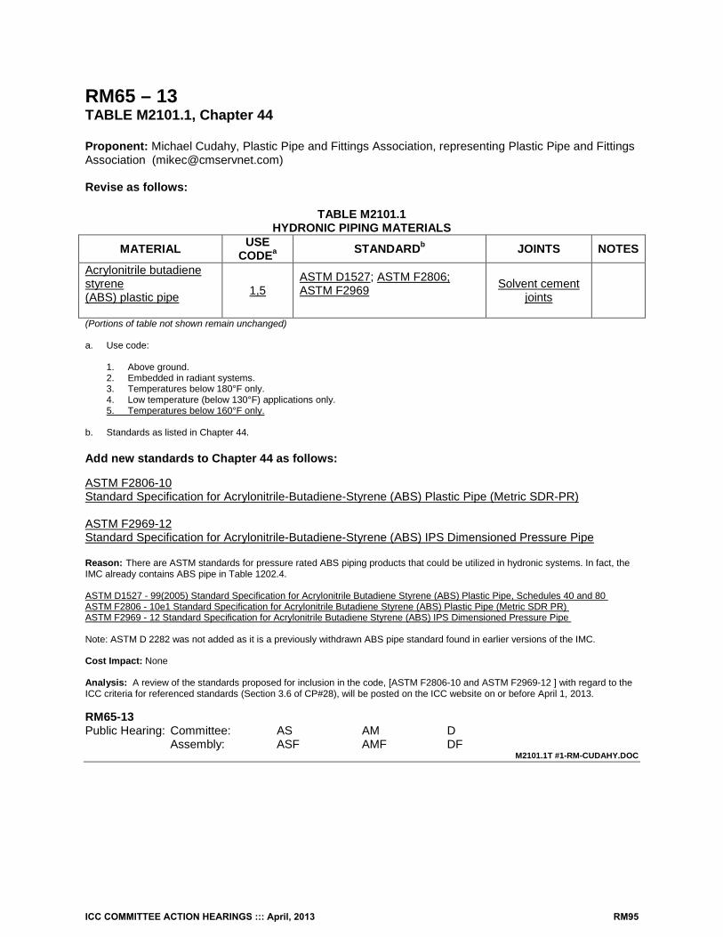
RM65 – 13 TABLE M2101.1, Chapter 44 Proponent: Michael Cudahy, Plastic Pipe and Fittings Association, representing Plastic Pipe and Fittings Association ([email protected]) Revise as follows:
TABLE M2101.1 HYDRONIC PIPING MATERIALS
MATERIAL USE CODEa STANDARDb JOINTS NOTES
Acrylonitrile butadiene styrene (ABS) plastic pipe
1,5 ASTM D1527; ASTM F2806; ASTM F2969
Solvent cement joints
(Portions of table not shown remain unchanged) a. Use code:
1. Above ground. 2. Embedded in radiant systems. 3. Temperatures below 180°F only. 4. Low temperature (below 130°F) applications only. 5. Temperatures below 160°F only.
b. Standards as listed in Chapter 44. Add new standards to Chapter 44 as follows: ASTM F2806-10 Standard Specification for Acrylonitrile-Butadiene-Styrene (ABS) Plastic Pipe (Metric SDR-PR) ASTM F2969-12 Standard Specification for Acrylonitrile-Butadiene-Styrene (ABS) IPS Dimensioned Pressure Pipe Reason: There are ASTM standards for pressure rated ABS piping products that could be utilized in hydronic systems. In fact, the IMC already contains ABS pipe in Table 1202.4. ASTM D1527 - 99(2005) Standard Specification for Acrylonitrile Butadiene Styrene (ABS) Plastic Pipe, Schedules 40 and 80 ASTM F2806 - 10e1 Standard Specification for Acrylonitrile Butadiene Styrene (ABS) Plastic Pipe (Metric SDR PR) ASTM F2969 - 12 Standard Specification for Acrylonitrile Butadiene Styrene (ABS) IPS Dimensioned Pressure Pipe Note: ASTM D 2282 was not added as it is a previously withdrawn ABS pipe standard found in earlier versions of the IMC. Cost Impact: None Analysis: A review of the standards proposed for inclusion in the code, [ASTM F2806-10 and ASTM F2969-12 ] with regard to the ICC criteria for referenced standards (Section 3.6 of CP#28), will be posted on the ICC website on or before April 1, 2013. RM65-13 Public Hearing: Committee: AS AM D Assembly: ASF AMF DF
M2101.1T #1-RM-CUDAHY.DOC
ICC COMMITTEE ACTION HEARINGS ::: April, 2013 RM95
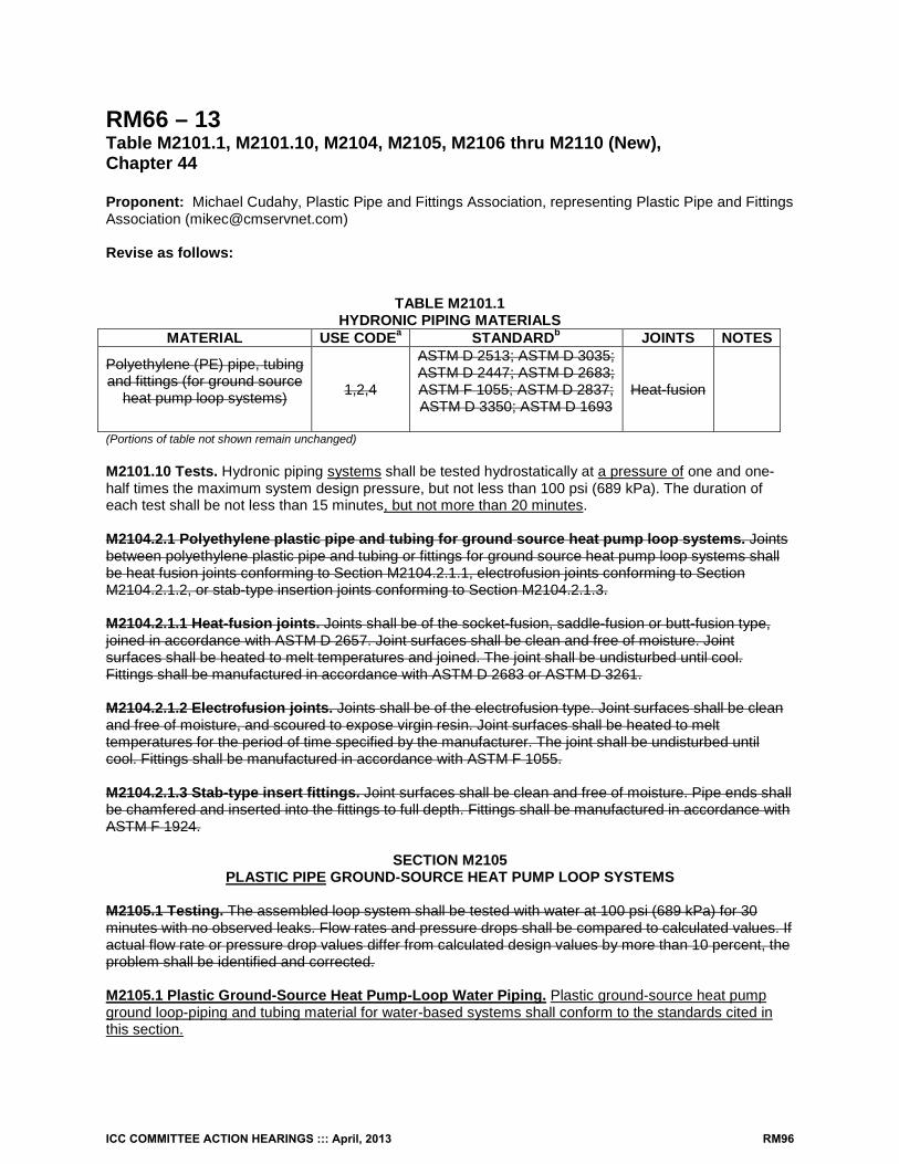
RM66 – 13 Table M2101.1, M2101.10, M2104, M2105, M2106 thru M2110 (New), Chapter 44 Proponent: Michael Cudahy, Plastic Pipe and Fittings Association, representing Plastic Pipe and Fittings Association ([email protected]) Revise as follows:
TABLE M2101.1 HYDRONIC PIPING MATERIALS
MATERIAL USE CODEa STANDARDb JOINTS NOTES
Polyethylene (PE) pipe, tubing and fittings (for ground source
heat pump loop systems)
1,2,4
ASTM D 2513; ASTM D 3035; ASTM D 2447; ASTM D 2683; ASTM F 1055; ASTM D 2837; ASTM D 3350; ASTM D 1693
Heat-fusion
(Portions of table not shown remain unchanged) M2101.10 Tests. Hydronic piping systems shall be tested hydrostatically at a pressure of one and one-half times the maximum system design pressure, but not less than 100 psi (689 kPa). The duration of each test shall be not less than 15 minutes, but not more than 20 minutes. M2104.2.1 Polyethylene plastic pipe and tubing for ground source heat pump loop systems. Joints between polyethylene plastic pipe and tubing or fittings for ground source heat pump loop systems shall be heat fusion joints conforming to Section M2104.2.1.1, electrofusion joints conforming to Section M2104.2.1.2, or stab-type insertion joints conforming to Section M2104.2.1.3. M2104.2.1.1 Heat-fusion joints. Joints shall be of the socket-fusion, saddle-fusion or butt-fusion type, joined in accordance with ASTM D 2657. Joint surfaces shall be clean and free of moisture. Joint surfaces shall be heated to melt temperatures and joined. The joint shall be undisturbed until cool. Fittings shall be manufactured in accordance with ASTM D 2683 or ASTM D 3261. M2104.2.1.2 Electrofusion joints. Joints shall be of the electrofusion type. Joint surfaces shall be clean and free of moisture, and scoured to expose virgin resin. Joint surfaces shall be heated to melt temperatures for the period of time specified by the manufacturer. The joint shall be undisturbed until cool. Fittings shall be manufactured in accordance with ASTM F 1055. M2104.2.1.3 Stab-type insert fittings. Joint surfaces shall be clean and free of moisture. Pipe ends shall be chamfered and inserted into the fittings to full depth. Fittings shall be manufactured in accordance with ASTM F 1924.
SECTION M2105 PLASTIC PIPE GROUND-SOURCE HEAT PUMP LOOP SYSTEMS
M2105.1 Testing. The assembled loop system shall be tested with water at 100 psi (689 kPa) for 30 minutes with no observed leaks. Flow rates and pressure drops shall be compared to calculated values. If actual flow rate or pressure drop values differ from calculated design values by more than 10 percent, the problem shall be identified and corrected. M2105.1 Plastic Ground-Source Heat Pump-Loop Water Piping. Plastic ground-source heat pump ground loop-piping and tubing material for water-based systems shall conform to the standards cited in this section.
ICC COMMITTEE ACTION HEARINGS ::: April, 2013 RM96
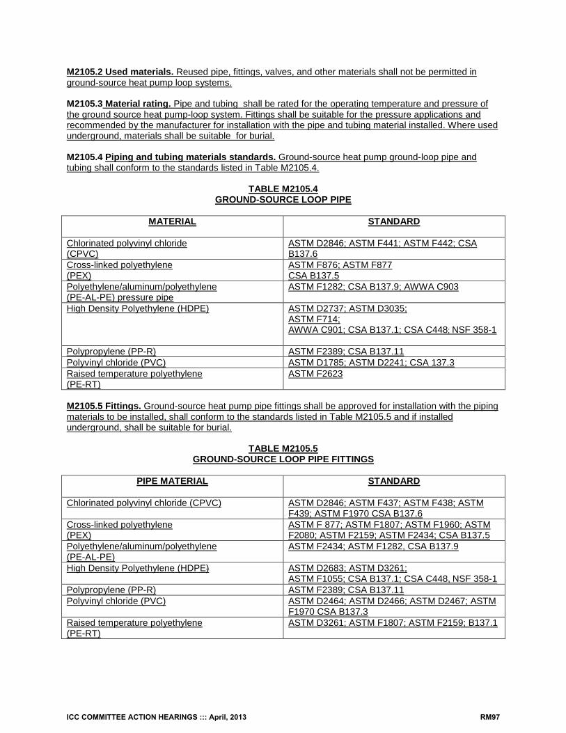
M2105.2 Used materials. Reused pipe, fittings, valves, and other materials shall not be permitted in ground-source heat pump loop systems. M2105.3 Material rating. Pipe and tubing shall be rated for the operating temperature and pressure of the ground source heat pump-loop system. Fittings shall be suitable for the pressure applications and recommended by the manufacturer for installation with the pipe and tubing material installed. Where used underground, materials shall be suitable for burial. M2105.4 Piping and tubing materials standards. Ground-source heat pump ground-loop pipe and tubing shall conform to the standards listed in Table M2105.4.
TABLE M2105.4
GROUND-SOURCE LOOP PIPE
MATERIAL STANDARD
Chlorinated polyvinyl chloride (CPVC)
ASTM D2846; ASTM F441; ASTM F442; CSA B137.6
Cross-linked polyethylene (PEX)
ASTM F876; ASTM F877 CSA B137.5
Polyethylene/aluminum/polyethylene (PE-AL-PE) pressure pipe
ASTM F1282; CSA B137.9; AWWA C903
High Density Polyethylene (HDPE) ASTM D2737; ASTM D3035; ASTM F714; AWWA C901; CSA B137.1; CSA C448; NSF 358-1
Polypropylene (PP-R) ASTM F2389; CSA B137.11 Polyvinyl chloride (PVC) ASTM D1785; ASTM D2241; CSA 137.3 Raised temperature polyethylene (PE-RT)
ASTM F2623
M2105.5 Fittings. Ground-source heat pump pipe fittings shall be approved for installation with the piping materials to be installed, shall conform to the standards listed in Table M2105.5 and if installed underground, shall be suitable for burial.
TABLE M2105.5 GROUND-SOURCE LOOP PIPE FITTINGS
PIPE MATERIAL STANDARD
Chlorinated polyvinyl chloride (CPVC) ASTM D2846; ASTM F437; ASTM F438; ASTM
F439; ASTM F1970 CSA B137.6 Cross-linked polyethylene (PEX)
ASTM F 877; ASTM F1807; ASTM F1960; ASTM F2080; ASTM F2159; ASTM F2434; CSA B137.5
Polyethylene/aluminum/polyethylene (PE-AL-PE)
ASTM F2434; ASTM F1282, CSA B137.9
High Density Polyethylene (HDPE) ASTM D2683; ASTM D3261; ASTM F1055; CSA B137.1; CSA C448, NSF 358-1
Polypropylene (PP-R) ASTM F2389; CSA B137.11 Polyvinyl chloride (PVC) ASTM D2464; ASTM D2466; ASTM D2467; ASTM
F1970 CSA B137.3 Raised temperature polyethylene (PE-RT)
ASTM D3261; ASTM F1807; ASTM F2159; B137.1
ICC COMMITTEE ACTION HEARINGS ::: April, 2013 RM97
SECTION M2106 JOINTS AND CONNECTIONS
M2106.1 Approval. Joints and connections shall be of an approved type. Joints and connections shall be tight for the pressure of the ground-source loop system. Joints used underground shall be approved for buried applications. M2106.1.1 Joints between different piping materials. Joints between different piping materials shall be made with approved transition fittings. M2106.2 Preparation of pipe ends. Pipe shall be cut square, reamed, and shall be free of burrs and obstructions. CPVC, PE, and PVC pipe shall be chamfered. Pipe ends shall have full-bore openings and shall not be undercut. M2106.3 Joint preparation and installation. Where required by Sections M2106.4 through M2106.6, the preparation and installation of mechanical and thermoplastic-welded joints shall comply with Sections M2106.3.1 and M2016.3.2. M2106.3.1 Mechanical joints. Mechanical joints shall be installed in accordance with the manufacturer’s instructions. M2106.3.2 Thermoplastic-welded joints. Joint surfaces for thermo plastic-welded joints shall be cleaned by an approved procedure. Joints shall be welded in accordance with the manufacturer’s instructions. M2106.4 CPVC plastic pipe. Joints between CPVC plastic pipe or fittings shall be solvent-cemented in accordance with Section P2905.9.1.2. Threaded joints between fittings and CPVC plastic pipe shall be in accordance with Section M2106.4.1. M1206.4.1 Threaded joints. Threads shall conform to ASME B1.20.1. Schedule 80 or heavier plastic pipe shall be threaded with dies specifically designed for plastic pipe. Thread lubricant, pipe-joint compound or tape shall be applied on the male threads only and shall be approved for application on the piping material. M2106.5 Cross-linked polyethylene (PEX) plastic tubing. Joints between cross-linked polyethylene plastic tubing and fittings shall comply with Sections M2106.5.1 and M2106.5.2. Mechanical joints shall comply with Section M2106.3.1. M2106.5.1 Compression-type fittings. Where compression- type fittings include inserts and ferrules or O-rings, the fittings shall be installed without omitting the inserts and ferrules or O-rings. M2106.5.2 Plastic-to-metal connections. Solder joints in a metal pipe shall not occur within 18 inches of a transition from such metal pipe to plastic pipe or tubing. M2106.6 Polyethylene plastic pipe and tubing for ground source heat pump loop systems. Joints between polyethylene plastic pipe and tubing or fittings for ground source heat pump loop systems shall be heat fusion joints complying with Section M2106.6.1, electrofusion joints complying with Section M2106.6.2, or stab-type insertion joints complying with Section M2106.6.3. M2106.6.1 Heat-fusion joints. Joints shall be of the socket-fusion, saddle-fusion or butt-fusion type, joined in accordance with ASTM D 2657. Joint surfaces shall be clean and free of moisture. Joint surfaces shall be heated to melt temperatures and joined. The joint shall be undisturbed until cool. Fittings shall be manufactured in accordance with ASTM D 2683 or ASTM D 3261.
M2106.6.2 Electrofusion joints. Joints shall be of the electrofusion type. Joint surfaces shall be clean and free of moisture, and scoured to expose virgin resin. Joint surfaces shall be heated to melt
ICC COMMITTEE ACTION HEARINGS ::: April, 2013 RM98
temperatures for the period of time specified by the manufacturer. The joint shall be undisturbed until cool. Fittings shall be manufactured in accordance with ASTM F 1055. M2106.6.3 Stab-type insert fittings. Joint surfaces shall be clean and free of moisture. Pipe ends shall be chamfered and inserted into the fittings to full depth. Fittings shall be manufactured in accordance with ASTM F 1924. M2106.7 Polypropylene (PP) plastic. Joints between PP plastic pipe and fittings shall comply with Sections M2106.7.1 and M2106.7.2. M2106.7.1 Heat-fusion joints. Heat-fusion joints for polypropylene (PP) pipe and tubing joints shall be installed with socket-type heat-fused polypropylene fittings, electrofusion polypropylene fittings or by butt fusion. Joint surfaces shall be clean and free from moisture. The joint shall be undisturbed until cool. Joints shall be made in accordance with ASTM F 2389. M2106.7.2 Mechanical and compression sleeve joints. Mechanical and compression sleeve joints shall be installed in accordance with the manufacturer’s instructions. M2106.8 Raised temperature polyethylene (PE-RT) plastic tubing. Joints between raised temperature polyethylene tubing and fittings shall complying with Sections M2016.8.1 and M2106.8.2. Mechanical joints shall comply with Section M2106.3.1. M2106.8.1 Compression-type fittings. Where compression-type fittings include inserts and ferrules or O-rings, the fittings shall be installed without omitting the inserts and ferrules or O-rings. M2106.8.2 PE-RT-to-metal connections. Solder joints in a metal pipe shall not occur within 18 inches (457 mm) of a transition from such metal pipe to PE-RT pipe. M2106.9 PVC plastic pipe. Joints between PVC plastic pipe or fittings shall be solvent-cemented in accordance with Section P2905.9.1.3. Threaded joints between fittings and PVC plastic pipe shall be in accordance with Section M2106.4.1.
SECTION M2107
VALVES M2107.1 Where required. Shutoff valves shall be installed in ground source-loop piping systems in the locations indicated in Sections M2107.1.1 through M2107.1.6. M2107.1.1 Heat exchangers. Shutoff valves shall be installed on the supply and return side of a heat exchanger.
Exception: Shutoff valves shall not be required where heat exchangers are integral with a boiler or are a component of a manufacturer’s boiler and heat exchanger packaged unit and are capable of being isolated from the hydronic system by the supply and return valves required by Section M2001.3.
M2107.1.2 Central systems. Shutoff valves shall be installed on the building supply and return of a central utility system. M2107.1.3 Pressure vessels. Shutoff valves shall be installed on the connection to any pressure vessel. M2107.1.4 Pressure-reducing valves. Shutoff valves shall be installed on both sides of a pressure-reducing valve.
ICC COMMITTEE ACTION HEARINGS ::: April, 2013 RM99
M2107.1.5 Equipment and appliances. Shutoff valves shall be installed on connections to mechanical equipment and appliances. This requirement does not apply to components of a ground-source loop system such as pumps, air separators, metering devices, and similar equipment. M2107.1.6 Expansion tanks. Shutoff valves shall be installed at connections to nondiaphragm-type expansion tanks. M2107.2 Reduced pressure. A pressure relief valve shall be installed on the low-pressure side of a hydronic piping system that has been reduced in pressure. The relief valve shall be set at the maximum pressure of the system design. The valve shall be installed in accordance with Section M2002.
SECTION M2108 PIPING INSTALLATION
M2108.1 General. Piping, valves, fittings, and connections shall be installed in accordance with the manufacturer’s instructions. M2108.3 Protection of potable water. Where ground-source heat pump ground loop systems have a connection to a potable water supply, the potable water system shall be protected from backflow in accordance with Section P2902. M2108.4 Pipe penetrations. Openings for pipe penetrations in walls, floors and ceilings shall be larger than the penetrating pipe. Openings through concrete or masonry building elements shall be sleeved. The annular space surrounding pipe penetrations shall be protected in accordance with Section P2606.1. M2108.5 Clearance from combustibles. A pipe in a ground source heat pump piping system having an exterior surface temperature exceeding 250°F (121°C) shall have a clearance of not less than 1 inch (25 mm) from combustible materials. M2108.6 Contact with building material. A ground-source heat pump ground-loop piping system shall not be in direct contact with building materials that cause the piping or fitting material to degrade or corrode, or that interfere with the operation of the system. M2108.7 Strains and stresses. Piping shall be installed so as to prevent detrimental strains and stresses in the pipe. Provisions shall be made to protect piping from damage resulting from expansion, contraction and structural settlement. Piping shall be installed so as to avoid structural stresses or strains within building components. M2108.7.1 Flood hazard. Piping located in a flood hazard area shall be capable of resisting hydrostatic and hydrodynamic loads and stresses, including the effects of buoyancy, during the occurrence of flooding to the design flood elevation. M2108.8 Pipe support. Pipe shall be supported in accordance with Section M2101.9. M2108.9 Velocities. Ground-source heat pump ground-loop systems shall be designed so that the flow velocities do not exceed the maximum flow velocity recommended by the pipe and fittings manufacturer. Flow velocities shall be controlled to reduce the possibility of water hammer. M2108.10 Labeling and Marking. Ground-source heat pump ground-loop system piping shall be marked with tape, metal tags or other methods where it enters a building. The marking shall indicate the following words: “GROUND SOURCE HEAT PUMP-LOOP SYSTEM”. The marking shall indicate any antifreeze used in the system by name and concentration. M2108.11 Chemical Compatibility. Antifreeze and other materials used in the system shall be chemically compatible with the pipe, tubing, fittings, and mechanical systems.
ICC COMMITTEE ACTION HEARINGS ::: April, 2013 RM100
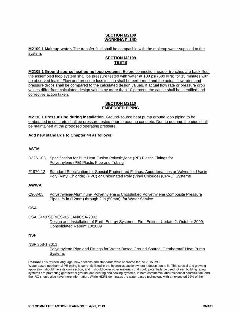
SECTION M2109 WORKING FLUID
M2109.1 Makeup water. The transfer fluid shall be compatible with the makeup water supplied to the system.
SECTION M2109 TESTS
M2109.1 Ground-source heat pump loop systems. Before connection header trenches are backfilled, the assembled loop system shall be pressure tested with water at 100 psi (689 kPa) for 15 minutes with no observed leaks. Flow and pressure loss testing shall be performed and the actual flow rates and pressure drops shall be compared to the calculated design values. If actual flow rate or pressure drop values differ from calculated design values by more than 10 percent, the cause shall be identified and corrective action taken.
SECTION M2110 EMBEDDED PIPING
M2110.1 Pressurizing during installation. Ground-source heat pump ground loop piping to be embedded in concrete shall be pressure tested prior to pouring concrete. During pouring, the pipe shall be maintained at the proposed operating pressure. Add new standards to Chapter 44 as follows: ASTM D3261-03 Specification for Butt Heat Fusion Polyethylene (PE) Plastic Fittings for
Polyethylene (PE) Plastic Pipe and Tubing F1970-12 Standard Specifcation for Special Engineered Fittings, Appurtenances or Valves for Use in
Poly (Vinyl Chloride) (PVC) or Chlorinated Poly (Vinyl Chloride) (CPVC) Systems AWWA C903-05 Polyethylene-Aluminum- Polyethylene & Crosslinked Polyethylene Composite Pressure
Pipes, ½ in (12mm) through 2 in (50mm), for Water Service CSA CSA C448 SERIES-02-CAN/CSA-2002
Design and Installation of Earth Energy Systems - First Edition; Update 2: October 2009; Consolidated Reprint 10/2009
NSF NSF 358-1 2011
Polyethylene Pipe and Fittings for Water-Based Ground-Source ‘Geothermal’ Heat Pump Systems
Reason: This revised language, new sections and standards were approved for the 2015 IMC. Water based geothermal PE piping is currently listed in the hydronics section where it doesn’t quite fit. This special and growing application should have its own section, and it should cover other materials that could potentially be used. Green building rating systems are promoting geothermal ground loop heating and cooling systems, in both commercial and residential construction, and the IRC should also have more information. While HDPE dominates the water based technology with an expected 95% of the
ICC COMMITTEE ACTION HEARINGS ::: April, 2013 RM101
systems, other piping materials can be utilized. Copper is used in direct expansion systems that do not run on water, but use refrigerants directly. The only minor modifications from the IMC language are in the following sections: M2108.1 General. Piping, valves, fittings, and connections shall be installed in accordance with the manufacturer’s instructions., as some were concerned by the language, “conditions of the approval. “ CSA B137.6, AWWA C903, and CSA B137.3 were added where appropriate to Table M2105.4 ASTM F1970 Standard Specification for Special Engineered Fittings, Appurtenances or valves for PVC and CPVC was added to table M2105.5. Cost Impact: None Analysis: A review of the standards proposed for inclusion in the code, [ASTM D3261-03, ASTM F1970-12; AWWA C903-05; CSA C448 Series-02-CAN/CSA-2002; NSF 358-1 2011] with regard to the ICC criteria for referenced standards (Section 3.6 of CP#28), will be posted on the ICC website on or before April 1, 2013. RM_-13 Public Hearing: Committee: AS AM D Assembly: ASF AMF DF
M2101.1T #2-RM-CUDAHY.DOC
ICC COMMITTEE ACTION HEARINGS ::: April, 2013 RM102
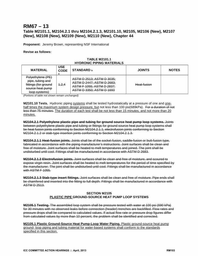
RM67 – 13 Table M2101.1, M2104.2.1 thru M2104.2.1.3, M2101.10, M2105, M2106 (New), M2107 (New), M2108 (New), M2109 (New), M2110 (New), Chapter 44 Proponent: Jeremy Brown, representing NSF International Revise as follows:
TABLE M2101.1 HYDRONIC PIPING MATERIALS
MATERIAL USE CODE a
STANDARD b JOINTS NOTES
Polyethylene (PE) pipe, tubing and
fittings (for ground source heat pump
loop systems)
1,2,4
ASTM D 2513; ASTM D 3035; ASTM D 2447; ASTM D 2683; ASTM F 1055; ASTM D 2837; ASTM D 3350; ASTM D 1693
Heat-fusion
(Portions of table not shown remain unchanged) M2101.10 Tests. Hydronic piping systems shall be tested hydrostatically at a pressure of one and one-half times the maximum system design pressure, but not less than 100 psi(689kPa). For a duration of not less than 75 minutes. The duration of each test shall be not less than 15 minutes, and not more than 20 minutes. M2104.2.1 Polyethylene plastic pipe and tubing for ground source heat pump loop systems. Joints between polyethylene plastic pipe and tubing or fittings for ground source heat pump loop systems shall be heat fusion joints conforming to Section M2104.2.1.1, electrofusion joints conforming to Section M2104.2.1.2 or stab-type insertion joints conforming to Section M2104.2.1.3. M2104.2.1.1 Heat-fusion joints. Joints shall be of the socket-fusion, saddle-fusion or butt-fusion type, fabricated in accordance with the piping manufacturer’s instructions. Joint surfaces shall be clean and free of moisture. Joint surfaces shall be heated to melt temperatures and joined. The joint shall be undisturbed until cool. Fittings shall be manufactured in accordance with ASTM D 2683. M2104.2.1.2 Electrofusion joints. Joint surfaces shall be clean and free of moisture, and scoured to expose virgin resin. Joint surfaces shall be heated to melt temperatures for the period of time specified by the manufacturer. The joint shall be undisturbed until cool. Fittings shall be manufactured in accordance with ASTM F 1055. M2104.2.1.3 Stab-type insert fittings. Joint surfaces shall be clean and free of moisture. Pipe ends shall be chamfered and inserted into the fitting to full depth. Fittings shall be manufactured in accordance with ASTM D 2513.
SECTION M2105 PLASTIC PIPE GROUND-SOURCE HEAT PUMP LOOP SYSTEMS
M2105.1 Testing. The assembled loop system shall be pressure tested with water at 100 psi (690 kPa) for 30 minutes with no observed leaks before connection (header) trenches are backfilled. Flow rates and pressure drops shall be compared to calculated values. If actual flow rate or pressure drop figures differ from calculated values by more than 10 percent, the problem shall be identified and corrected. M2105.1 Plastic Ground-Source Heat Pump-Loop Water Piping. Plastic ground-source heat pump ground- loop piping and tubing material for water-based systems shall conform to the standards specified in this section.
ICC COMMITTEE ACTION HEARINGS ::: April, 2013 RM103
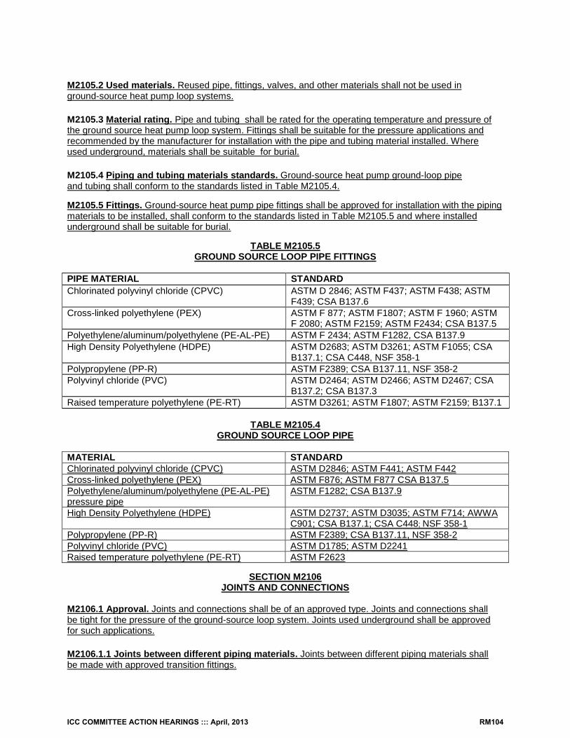
M2105.2 Used materials. Reused pipe, fittings, valves, and other materials shall not be used in ground-source heat pump loop systems. M2105.3 Material rating. Pipe and tubing shall be rated for the operating temperature and pressure of the ground source heat pump loop system. Fittings shall be suitable for the pressure applications and recommended by the manufacturer for installation with the pipe and tubing material installed. Where used underground, materials shall be suitable for burial. M2105.4 Piping and tubing materials standards. Ground-source heat pump ground-loop pipe and tubing shall conform to the standards listed in Table M2105.4. M2105.5 Fittings. Ground-source heat pump pipe fittings shall be approved for installation with the piping materials to be installed, shall conform to the standards listed in Table M2105.5 and where installed underground shall be suitable for burial.
TABLE M2105.5 GROUND SOURCE LOOP PIPE FITTINGS
PIPE MATERIAL STANDARD Chlorinated polyvinyl chloride (CPVC) ASTM D 2846; ASTM F437; ASTM F438; ASTM
F439; CSA B137.6 Cross-linked polyethylene (PEX) ASTM F 877; ASTM F1807; ASTM F 1960; ASTM
F 2080; ASTM F2159; ASTM F2434; CSA B137.5 Polyethylene/aluminum/polyethylene (PE-AL-PE) ASTM F 2434; ASTM F1282, CSA B137.9 High Density Polyethylene (HDPE) ASTM D2683; ASTM D3261; ASTM F1055; CSA
B137.1; CSA C448, NSF 358-1 Polypropylene (PP-R) ASTM F2389; CSA B137.11, NSF 358-2 Polyvinyl chloride (PVC) ASTM D2464; ASTM D2466; ASTM D2467; CSA
B137.2; CSA B137.3 Raised temperature polyethylene (PE-RT) ASTM D3261; ASTM F1807; ASTM F2159; B137.1
TABLE M2105.4
GROUND SOURCE LOOP PIPE
MATERIAL STANDARD Chlorinated polyvinyl chloride (CPVC) ASTM D2846; ASTM F441; ASTM F442 Cross-linked polyethylene (PEX) ASTM F876; ASTM F877 CSA B137.5 Polyethylene/aluminum/polyethylene (PE-AL-PE) pressure pipe
ASTM F1282; CSA B137.9
High Density Polyethylene (HDPE) ASTM D2737; ASTM D3035; ASTM F714; AWWA C901; CSA B137.1; CSA C448; NSF 358-1
Polypropylene (PP-R) ASTM F2389; CSA B137.11, NSF 358-2 Polyvinyl chloride (PVC) ASTM D1785; ASTM D2241 Raised temperature polyethylene (PE-RT) ASTM F2623
SECTION M2106 JOINTS AND CONNECTIONS
M2106.1 Approval. Joints and connections shall be of an approved type. Joints and connections shall be tight for the pressure of the ground-source loop system. Joints used underground shall be approved for such applications. M2106.1.1 Joints between different piping materials. Joints between different piping materials shall be made with approved transition fittings.
ICC COMMITTEE ACTION HEARINGS ::: April, 2013 RM104
M2106.2 Preparation of pipe ends. Pipe shall be cut square, reamed, and shall be free of burrs and obstructions. CPVC, PE, and PVC pipe shall be chamfered. Pipe ends shall have full-bore openings and shall not be undercut. M2106.3 Joint preparation and installation. Where required by Sections M2106.4 through M2106.6, the preparation and installation of mechanical and thermoplastic-welded joints shall comply with Sections M2106.3.1 and M2016.3.2. M2106.3.1 Mechanical joints. Mechanical joints shall be installed in accordance with the manufacturer’s instructions. M2106.3.2 Thermoplastic-welded joints. Joint surfaces for thermo plastic-welded joints shall be cleaned by an approved procedure. Joints shall be welded in accordance with the manufacturer’s instructions. M2106.4 CPVC plastic pipe. Joints between CPVC plastic pipe or fittings shall be solvent-cemented in accordance with Section P2905.9.1.2. Threaded joints between fittings and CPVC plastic pipe shall be in accordance with Section M2106.4.1. M1206.4.1 Threaded joints. Threads shall conform to ASME B1.20.1. The pipe shall be Schedule 80 or heavier and shall be threaded with dies specifically designed for plastic pipe. Thread lubricant, pipe-joint compound or tape shall be applied on the male threads only and shall be approved for application on the piping material. M2106.5 Cross-linked polyethylene (PEX) plastic tubing. Joints between cross-linked polyethylene plastic tubing and fittings shall comply with Sections M2106.5.1 and M2106.5.2. Mechanical joints shall comply with Section M2106.3.1. M2106.5.1 Compression-type fittings. Where compression-type fittings include inserts and ferrules or O-rings, the fittings shall be installed without omitting the inserts and ferrules or O-rings. M2106.5.2 Plastic-to-metal connections. Solder joints in a metal pipe shall not occur within 18 inches of a transition from such metal pipe to plastic pipe or tubing. M2106.6 Polyethylene plastic pipe and tubing for ground source heat pump loop systems. Joints between polyethylene plastic pipe and tubing or fittings for ground-source heat pump loop systems shall be heat fusion joints complying with Section M2106.6.1, electrofusion joints complying with Section M2106.6.2, or stab-type insertion joints complying with Section M2106.6.3. M2106.6.1 Heat-fusion joints. Joints shall be of the socket-fusion, saddle-fusion or butt-fusion type, and joined in accordance with ASTM D 2657. Joint surfaces shall be clean and free of moisture. Joint surfaces shall be heated to melt temperatures and joined. The joint shall be undisturbed until cool. Fittings shall be manufactured in accordance with ASTM D 2683 or ASTM D 3261. M2106.6.2 Electrofusion joints. Joints shall be of the electrofusion type. Joint surfaces shall be clean and free of moisture, and scoured to expose virgin resin. Joint surfaces shall be heated to melt temperatures for the period of time specified by the manufacturer. The joint shall be undisturbed until cool. Fittings shall be manufactured in accordance with ASTM F 1055. M2106.6.3 Stab-type insert fittings. Joint surfaces shall be clean and free of moisture. Pipe ends shall be chamfered and inserted into the fittings to full depth. Fittings shall be manufactured in accordance with ASTM F 1924. M2106.7 Polypropylene (PP) plastic. Joints between PP plastic pipe and fittings shall comply with Sections M2106.7.1 and M2106.7.2.
ICC COMMITTEE ACTION HEARINGS ::: April, 2013 RM105
M2106.7.1 Heat-fusion joints. Heat-fusion joints for polypropylene (PP) pipe and tubing joints shall be installed with socket-type heat-fused polypropylene fittings, electrofusion polypropylene fittings or by butt fusion. Joint surfaces shall be clean and free from moisture. The joint shall be undisturbed until cool. Joints shall be made in accordance with ASTM F 2389. M2106.7.2 Mechanical and compression sleeve joints. Mechanical and compression sleeve joints shall be installed in accordance with the manufacturer’s instructions. M2106.8 Raised temperature polyethylene (PE-RT) plastic tubing. Joints between raised temperature polyethylene tubing and fittings shall complying with Sections M2016.8.1 and M2106.8.2. Mechanical joints shall comply with Section M2106.3.1. M2106.8.1 Compression-type fittings. Where compression-type fittings include inserts and ferrules or O-rings, the fittings shall be installed without omitting the inserts and ferrules or O-rings. M2106.8.2 PE-RT-to-metal connections. Solder joints in a metal pipe shall not occur within 18 inches of a transition from such metal pipe to plastic pipe or tubing. M2106.9 PVC plastic pipe. Joints between PVC plastic pipe or fittings shall be solvent-cemented in accordance with Section P2905.9.1.3. Threaded joints between fittings and PVC plastic pipe shall be in accordance with Section M2106.4.1.
SECTION M2107 VALVES
M2107.1 Where required. Shutoff valves shall be installed in ground-source loop piping systems in the locations indicated in Sections M2107.1.1 through M2107.1.6. M2107.1.1 Heat exchangers. Shutoff valves shall be installed on the supply and return side of a heat exchanger.
Exception: Shutoff valves shall not be required where heat exchangers are integral with a boiler or are a component of a manufacturer’s boiler and heat exchanger packaged unit and are capable of being isolated from the hydronic system by the supply and return valves required by Section M2001.3.
M2107.1.2 Central systems. Shutoff valves shall be installed on the building supply and return of a central utility system. M2107.1.3 Pressure vessels. Shutoff valves shall be installed on the connection to any pressure vessel. M2107.1.4 Pressure-reducing valves. Shutoff valves shall be installed on both sides of a pressure-reducing valve. M2107.1.5 Equipment and appliances. Shutoff valves shall be installed on connections to mechanical equipment and appliances. This requirement does not apply to components of a ground-source loop system such as pumps, air separators, metering devices, and similar equipment. M2107.1.6 Expansion tanks. Shutoff valves shall be installed at connections to nondiaphragm-type expansion tanks. M2107.2 Reduced pressure. A pressure relief valve shall be installed on the low-pressure side of a hydronic piping system that has been reduced in pressure. The relief valve shall be set at the
ICC COMMITTEE ACTION HEARINGS ::: April, 2013 RM106
maximum pressure of the system design. The valve shall be installed in accordance with Section M2002.
SECTION M2108 PIPING INSTALLATION
M2108.1 General. Piping, valves, fittings, and connections shall be installed in accordance with the manufacturer’s instructions. M2108.3 Protection of potable water. Where ground-source heat pump ground-loop systems have a connection to a potable water supply, the potable water system shall be protected from backflow in accordance with Section P2902. M2108.4 Pipe penetrations. Openings for pipe penetrations in walls, floors and ceilings shall be larger than the penetrating pipe. Openings through concrete and masonry building elements shall be sleeved. The annular space surrounding pipe penetrations shall be protected in accordance with Section P2606.1. M2108.5 Clearance from combustibles. A pipe in a ground source heat pump piping system having an exterior surface temperature exceeding 250°F (121°C) shall have a clearance of not less than 1 inch (25 mm) from combustible materials. M2108.6 Contact with building material. A ground-source heat pump ground-loop piping system shall not be in direct contact with building materials that cause the piping or fitting material to degrade or corrode, or that interfere with the operation of the system. M2108.7 Strains and stresses. Piping shall be installed so as to prevent detrimental strains and stresses in the pipe. Provisions shall be made to protect piping from damage resulting from expansion, contraction and structural settlement. Piping shall be installed so as to avoid structural stresses or strains within building components. M2108.7.1 Flood hazard. Piping located in a flood hazard area shall be capable of resisting hydrostatic and hydrodynamic loads and stresses, including the effects of buoyancy, during the occurrence of flooding to the design flood elevation. M2108.8 Pipe support. Pipe shall be supported in accordance with Section M2101.9. M2108.9 Velocities. Ground-source heat pump ground-loop systems shall be designed so that the flow velocities do not exceed the maximum flow velocity recommended by the pipe and fittings manufacturer. Flow velocities shall be controlled to reduce the possibility of water hammer. M2108.10 Labeling and Marking. Ground-source heat pump ground-loop system piping shall be marked with tape, metal tags or other methods where it enters a building. The marking shall state the following words: “GROUND-SOURCE HEAT PUMP LOOP SYSTEM”. The marking shall indicate if antifreezes used in the system and shall indicate the chemicals by name and concentration. M2108.11 Chemical Compatibility. Antifreeze and other materials used in the system shall be chemically compatible with the pipe, tubing, fittings, and mechanical systems.
SECTION M2109 WORKING FLUID
M2109.1 Makeup water. The transfer fluid in ground-source heat pump systems shall be compatible with the makeup water supplied to the system.
ICC COMMITTEE ACTION HEARINGS ::: April, 2013 RM107
SECTION M2110 TESTS
M2109.1 Testing. Before connection header trenches are backfilled, the assembled loop system shall be pressure tested with water at 100 psi (689 kPa) for 15 minutes with no observed leaks. Flow and pressure loss testing shall be performed and the actual flow rates and pressure drops shall be compared to the calculated design values. If actual flow rate or pressure drop values differ from calculated design values by more than 10 percent, the cause shall be identified and corrective action taken.
SECTION M2111 EMBEDDED PIPING
M2110.1 Pressurizing during installation. Ground-source heat pump ground-loop piping to be embedded in concrete shall be pressure tested prior to pouring concrete. During pouring, the pipe shall be maintained at the proposed operating pressure. Add new standards to Chapter 44 as follows: ASTM ASTM D3261 -03 Specification for Butt Heat Fusion Polyethylene (PE) Plastic Fittings for Polyethylene (PE) Plastic Pipe and Tubing ASTM F1924-05 Standard Specification for Plastic Mechanical Fittings for Use on Outside Diameter Controlled Polyethylene Gas Distribution Pipe and Tubing CSA CSA C448 SERIES-02-CAN/CSA-2002 Design and Installation of Earth Energy Systems -First Edition; Update 2: October 2009; Consolidated Reprint 10/2009 NSF NSF 358-1 2011 Polyethylene Pipe and Fittings for Water-Based Ground-Source ‘Geothermal’ Heat Pump Systems NSF 358-2 2012 Polypropylene Pipe and Fittings for Water-Based Ground-Source ‘Geothermal’ Heat Pump Systems. Reason: This revised language, new sections and standards were approved for the 2015 IMC. A companion Code change has been submitted by PPFA. My only change to their proposal is to add one additional standard NSF 358-2, which at the time of submittal of this code change was not published yet. This standard is expected to be published in February 2013 and made available for free by contacting the proponent at [email protected] for consideration of this code change. Cost Impact: This will not increase the cost of construction. Analysis: A review of the standards proposed for inclusion in the code, [ASTM D3261-03, F1924-05; CSA C448 Series-02-CAN/CSA-2002; NSF 358-1 2011, and 358-2 2012] with regard to the ICC criteria for referenced standards (Section 3.6 of CP#28, will be posted on the ICC website on or before April 1, 2013. RM67-13 Public Hearing: Committee: AS AM D Assembly: ASF AMF DF
M2101.1T-RM-BROWN.DOC
ICC COMMITTEE ACTION HEARINGS ::: April, 2013 RM108
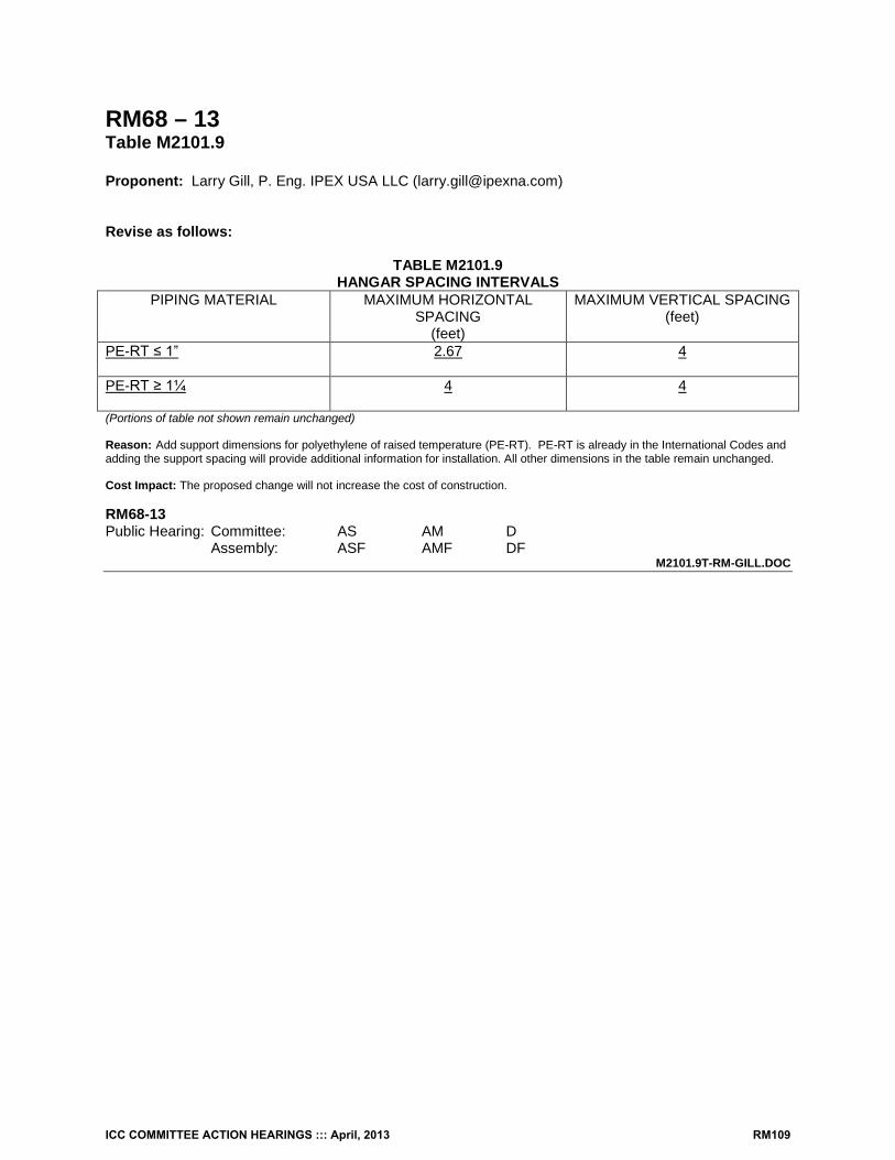
RM68 – 13 Table M2101.9 Proponent: Larry Gill, P. Eng. IPEX USA LLC ([email protected]) Revise as follows:
TABLE M2101.9 HANGAR SPACING INTERVALS
PIPING MATERIAL MAXIMUM HORIZONTAL SPACING
(feet)
MAXIMUM VERTICAL SPACING (feet)
PE-RT ≤ 1”
2.67 4
PE-RT ≥ 1¼
4 4
(Portions of table not shown remain unchanged) Reason: Add support dimensions for polyethylene of raised temperature (PE-RT). PE-RT is already in the International Codes and adding the support spacing will provide additional information for installation. All other dimensions in the table remain unchanged. Cost Impact: The proposed change will not increase the cost of construction. RM68-13 Public Hearing: Committee: AS AM D Assembly: ASF AMF DF
M2101.9T-RM-GILL.DOC
ICC COMMITTEE ACTION HEARINGS ::: April, 2013 RM109
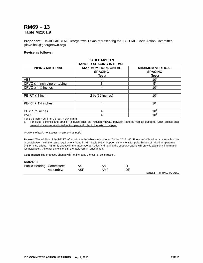
RM69 – 13 Table M2101.9 Proponent: David Hall CFM, Georgetown Texas representing the ICC PMG Code Action Committee ([email protected]) Revise as follows:
TABLE M2101.9 HANGER SPACING INTERVAL
PIPING MATERIAL MAXIMUM HORIZONTAL SPACING
(feet)
MAXIMUM VERTICAL SPACING
(feet) ABS 4 10a CPVC ≤ 1 inch pipe or tubing 3 5a CPVC ≥ 1 ¼ inches 4 10a PE-RT ≤ 1 inch
2 ⅔ (32 inches) 10a
PE-RT ≥ 1¼ inches
4 10a
PP ≥ 1 ¼ inches 4 10a PVC 4 10a For SI: 1 inch = 25.4 mm, 1 foot = 304.8 mm a. For sizes 2 inches and smaller, a guide shall be installed midway between required vertical supports. Such guides shall
prevent pipe movement in a direction perpendicular to the axis of the pipe. (Portions of table not shown remain unchanged.) Reason: The addition of the PE-RT information to the table was approved for the 2015 IMC. Footnote “a” is added to the table to be in coordination with the same requirement found in IMC Table 305.4. Support dimensions for polyethylene of raised temperature (PE-RT) are added. PE-RT is already in the International Codes and adding the support spacing will provide additional information for installation. All other dimensions in the table remain unchanged. Cost Impact: The proposed change will not increase the cost of construction. RM69-13 Public Hearing: Committee: AS AM D Assembly: ASF AMF DF
M2101.9T-RM-HALL-PMGCAC
ICC COMMITTEE ACTION HEARINGS ::: April, 2013 RM110
RM70 – 13 M2103.1 Proponent: Pennie L. Feehan, Pennie L. Feehan Consulting, representing Copper Development Association ([email protected]) Revise as follows: M2103.1 Piping materials. Piping for embedment in concrete or gypsum materials shall be standard-weight steel pipe, copper and copper alloy pipe and tubing, cross-linked polyethylene/aluminum/crosslinked polyethylene (PEX-AL-PEX) pressure pipe, chlorinated polyvinyl chloride (CPVC), polybutylene, cross-linked polyethylene (PEX) tubing or polypropylene (PP) with a minimum rating of 100 psi at 180°F (690 kPa at 82°C). Reason: Brass and Bronze are copper alloys and by adding copper alloys this proposal provides the appropriate terminology and correct information to the end user. Cost Impact: None RM70-13 Public Hearing: Committee: AS AM D Assembly: ASF AMF DF
M2103.1-RM-FEEHAN.DOC
ICC COMMITTEE ACTION HEARINGS ::: April, 2013 RM111
RM71 – 13 M2103.1 Proponent: Larry Gill, P. Eng. IPEX USA LLC ([email protected]) Revise as follows: M2103.1 Piping materials. Piping for embedment in concrete or gypsum materials shall be standard weight steel pipe, copper tubing, cross linked polyethylene aluminum polyethylene (PEX-AL-PEX) pressure pipe, chlorinated polyvinyl chloride (CPVC), polybutylene, cross-linked polyethylene (PEX) tubing, polyethylene of raised temperature (PE-RT) or polypropylene (PP) with a minimum rating of 100psi at 180°F (690kPa at 82°C). Reason: Add polyethylene of raised temperature (PE-RT) to the piping materials section. PE-RT meets all of the requirements of Chapter 21. Cost Impact: The proposed change will not increase the cost of construction. RM71-13 Public Hearing: Committee: AS AM D Assembly: ASF AMF DF
M2103.1-RM-GILL.DOC
ICC COMMITTEE ACTION HEARINGS ::: April, 2013 RM112
RM72 – 13 M2103.3, Chapter 44 Proponent: Pennie L. Feehan, Pennie L. Feehan Consulting, representing Copper Development Association ([email protected]) Revise as follows: M2103.3 Piping joints. Copper and copper alloys systems shall be soldered in accordance with ASTM B828. Fluxes for soldering shall be in accordance with ASTM B813 and shall become noncorrosive and non-toxic after soldering. Brazing fluxes shall be in accordance with AWS A5.31. Piping joints that are embedded shall be installed in accordance with the following requirements: Add new standard to Chapter 44 as follows: ANSI/AWS A5.31M/A5.31:2012 Specification for Fluxes for Brazing and Braze Welding Edition: 2nd Reason: Because hydronic systems are not potable system, inspectors and installers are not following the proper methods of installing copper pipe and tubing. Fluxes used for soldering copper tube and fittings must meet the requirements of ASTM B813. Cost Impact: None Analysis: A review of the standard proposed for inclusion in the code, [ANSI/AWS A5.31M/A5.31-2012] with regard to the ICC criteria for referenced standards (Section 3.6 of CP#28) will be posted on the ICC website on or before April 1, 2013. RM72-13 Public Hearing: Committee: AS AM D Assembly: ASF AMF DF
M2103.3-RM-FEEHAN.DOC
ICC COMMITTEE ACTION HEARINGS ::: April, 2013 RM113
RM73 – 13 M2103.3, Chapter 44 Proponent: Larry Gill, P. Eng. IPEX USA LLC ([email protected]) Revise as follows: M2103.3 Piping joints. Piping joints that are embedded shall be installed in accordance with the following requirements:
1. Steel pipe joints shall be welded. 2. Copper tubing shall be joined with brazing material having a melting point exceeding 1,000°F
(538°C). 3. Polybutylene pipe and tubing joints shall be installed with socket-type heat-fused polybutylene
fittings. 4. CPVC tubing shall be joined using solvent cement joints. 5. Polypropylene pipe and tubing joints shall be installed with socket-type heat-fused polypropylene
fittings. 6. Cross-linked polyethylene (PEX) tubing shall be joined using cold expansion, insert or
compression fittings. 7. Raised temperature polyethylene (PE-RT) tubing shall be joined using insert or compression
fittings.
TABLE M2101.1 HYDRONIC PIPING MATERIALS
MATERIAL USE CODEª STANDARDb JOINTS NOTES Raised Temperature Polyethylene (PE-RT)
1,2,3 ASTM F 2623 ASTM F 2769
Copper crimp/insert fitting stainless steel clamp, insert fittings
Raised Temperature Polyethylene (PE-RT) fittings
1,2,3 ASTM F1807 ASTM F2159 ASTM F2735 ASTM F2769 ASTM F2098
Copper crimp/insert fitting stainless steel clamp, insert fittings
Reason: Revise clause M2103.3 to include provisions for Raised Temperature Polyethylene (PE-RT) tubing. Revise Table M2101.1 to add PE-RT system standard ASTM F2769 (ASTM F2769 is a standard for hot and cold water tubing and distribution systems and includes provisions for tubing, fittings, valves and manifolds) for hydronic piping materials. Add the ASTM standards for fittings to be used with PE-RT. All of these standards are consensus based ASTM standards. Cost Impact: The proposed change will not increase the cost of construction. RM73-13 Public Hearing: Committee: AS AM D Assembly: ASF AMF DF
M2103.3-RM-GILL.DOC
ICC COMMITTEE ACTION HEARINGS ::: April, 2013 RM114
RM74 – 13 M2103.3 Proponent: David Hall CFM, Georgetown Texas representing the ICC PMG Code Action Committee ([email protected]) Revise as follows: M2103.3 Piping joints. Piping joints that are embedded shall be installed in accordance with the following requirements:
1. Steel pipe joints shall be welded. 2. Copper tubing shall be joined with by brazing complying with Section P3003.5.1. material having
a melting point exceeding 1,000°F (538°C). 3. Polybutylene pipe and tubing joints shall be installed with socket-type heat-fused polybutylene
fittings. 4. CPVC tubing shall be joined using solvent cement joints. 5. Polypropylene pipe and tubing joints shall be installed with socket-type heat-fused polypropylene
fittings. 6. Cross-linked polyethylene (PEX) tubing shall be joined using cold expansion, insert or
compression fittings. Reason: This revised language was approved for the 2015 IMC. The proposed language refers the end user to the appropriate code section with important language from the applicable standards. Cost Impact: This code change will not increase the cost of construction. RM74-13 Public Hearing: Committee: AS AM D Assembly: ASF AMF DF
M2103.3-RM-HALL-PMGCAC
ICC COMMITTEE ACTION HEARINGS ::: April, 2013 RM115
RM75 – 13 M2104.2, M2104.3 Proponent: Larry Gill, P.Eng. IPEX USA LLC Revise as follows: M2104.2 Piping Joints. Piping joints, other than those in Section M2103.3, that are embedded shall comply with the following requirements:
1. Cross-Linked Polyethylene (PEX) tubing shall be installed in accordance the manufacturer’s instructions.
2. Polyethylene tubing shall be installed with heat fusion joints. 3. Polypropylene (PP) shall be installed in accordance with the manufacturer’s instructions. 4. Raised temperature polyethylene (PE-RT) shall be installed in accordance with the
manufacturer’s instructions.
M2104.3 Raised temperature polyethylene (PE-RT) plastic tubing. Joints between raised temperature polyethylene tubing and fittings shall conform to Sections M2104.3.1, and M2104.3.2 and M2104.3.3. Mechanical joints shall be installed in accordance with the manufacturer’s instructions. M2104.3.1 Compression-type fittings. Where compression-type fittings include inserts and ferrules or O rings the fittings shall be installed without omitting such inserts and ferrules or O-rings. M2104.3.2 PE-RT to metal connections. Solder joints in a metal pipe shall not occur within 18 inches (457 mm) of a transition of such metal pipe to PE-RT pipe. M2104.3.3 PE-RT insert fittings. PE-RT insert fittings shall be installed in accordance with the manufacturer’s instructions. Reason: Add Polyethylene of Raised Temperature (PE-RT) to sections M2104.2 and M2104.3 to mandate that manufacturers instructions must be adhered to and that insert fittings must be installed in accordance with manufacturers instructions. Cost Impact: The proposed change will not increase the cost of construction. R75_-13 Public Hearing: Committee: AS AM D Assembly: ASF AMF DF
M2104.2-RM-GILL.doc
ICC COMMITTEE ACTION HEARINGS ::: April, 2013 RM116
RM76 – 13 M2202.1, Chapter 44 Proponent: Pennie L. Feehan, Pennie L. Feehan Consulting representing Copper Development Association ([email protected]) Revise as follows: M2202.1 Materials. Piping shall consist of steel pipe, copper and copper alloys pipe and tubing or steel tubing conforming to ASTM A539. Aluminum tubing shall not be used between the fuel-oil tank and the burner units. Add new standard to Chapter 44 as follows: ANSI/AWS A5.31M/A5.31:2012 Specification for Fluxes for Brazing and Braze Welding Edition: 2nd Reason: Because special piping systems are not potable system, inspectors and installers are not following the proper methods of installing copper pipe and tubing. Fluxes used for soldering copper tube and fittings must meet the requirements of ASTM B813. This proposal provides the appropriate terminology and correct information to the end user. Cost Impact: None Analysis: A review of the standard proposed for inclusion in the code, [ANSI/AWS A5.31M/A5.31-2012] with regard to the ICC criteria for referenced standards (Section 3.6 of CP#28) will be posted on the ICC website on or before April 1, 2013. RM76-13 Public Hearing: Committee: AS AM D Assembly: ASF AMF DF
M2202.1-RM-FEEHAN.DOC
ICC COMMITTEE ACTION HEARINGS ::: April, 2013 RM117
RM77 – 13 M2301.2.2 (New), M2301.2.2, M2301.2.2.2 (New), Chapter 44 Proponent: David Hall, Vice Chair, Plumbing/Mechanical/Gas Code Action Committee, ([email protected]) and Brenda A. Thompson, Clark County Building Department, Las Vegas NV, Chair, Sustainability, Energy & High Performance Code Action Committee ([email protected]) Revise as follows: M2301.2.2 Collectors and panels. Solar collectors and panels shall comply with Sections M2301.2.2.1 and M2301.2.2.2. M2301.2.2.1 M2301.2.2 Roof-mounted collectors. The roof shall be constructed to support the loads imposed by roof-mounted solar collectors. Roof-mounted solar collectors that serve as a roof covering shall conform to the requirements for roof coverings in Chapter 9 of this code. Where mounted on or above the roof coverings, the collectors and supporting structure shall be constructed of noncombustible materials or fire-retardant-treated wood equivalent to that required for the roof construction. M2301.2.2.2 Collector sensors. Collector sensor installation, sensor location and the protection of exposed sensor wires from ultraviolet light shall be in accordance with SRCC 300. Add new standard to Chapter 44 as follows: SRCC Solar Rating & Certification Corporation 400 High Point Drive, Suite 400 Cocoa, Florida 32926
SRCC 300-13 Standard 300 For Solar Water Heating Systems
Reason: This proposal is submitted by the ICC Plumbing, Mechanical and Fuel Gas Code Action Committee (PMGCAC) and the ICC Sustainability Energy and High Performance Code Action Committee (SEHPCAC). The PMGCAC and SEHPCAC were established by the ICC Board of Directors to pursue opportunities to improve and enhance assigned International Codes or portions thereof. This includes both the technical aspects of the codes as well as the code content in terms of scope and application of referenced standards. Since their inception in July, 2011, the PMGCAC and SEHPCAC have held multiple open meetings and conference calls and workgroup calls which included members of the PMGCAC and SEHPCAC. Interested parties also participated in all of the meetings and conference calls to discuss and debate the proposed changes.
This proposal revises existing Section M2301.2.2 into a parent section and two subsections. This was done in order to reference requirements related to collector sensors that are contained in SRCC 300. These collector sensor requirements are based on the manner in which the New York State Field Inspection Guidelines for Solar Heating Systems reference the SRCC standards.
Please note that the proponents have also submitted other proposals that are coordinated with this proposal. In the spirit of the IRC as a one stop code for one- and two-family dwellings and townhouses, these proposals enhance, update, clarify and improve the usability of the solar energy provisions of Chapter 23 of the IRC and make it truly comprehensive and much more direct and intuitive. This proposal, however, is intended to stand alone and is not contingent upon the success of other PMGCAC or SEHPCAC proposals. Cost Impact: Where solar systems are provided, this proposal may increase the cost of construction. Analysis: A review of the standard proposed for inclusion in the code, [SRCC 300-13] with regard to the ICC criteria for referenced standards (Section 3.6 of CP#28), will be posted on the ICC website on or before April 1, 2013. RM77-13 Public Hearing: Committee: AS AM D Assembly: ASF AMF DF
M2301.2.2 (NEW)-RM-HALL-THOMPSON-SEHPCAC.DOC
ICC COMMITTEE ACTION HEARINGS ::: April, 2013 RM118
RM78– 13 2301 (New) Proponent: David Hall, Vice Chair, Plumbing/Mechanical/Gas Code Action Committee, ([email protected]) and Brenda A. Thompson, Clark County Building Department, Las Vegas NV, Chair, Sustainability, Energy & High Performance Code Action Committee ([email protected]) Add new text as follows:
SECTION M2301
GENERAL M2301.1 General. This chapter provides for the design, construction, installation, alteration and repair of solar energy systems. Solar thermal systems shall comply with Section M2301 and Section 2302. Photovoltaic solar energy systems shall comply with Section 2301 and Section 2303. M2301.2 Ground mounted collectors, panels and modules. Ground mounted solar collectors, panels and modules shall be subject to the fire separation distance requirements of Section R302.1. Reason: This proposal is submitted by the ICC Plumbing, Mechanical and Fuel Gas Code Action Committee (PMGCAC) and the ICC Sustainability Energy and High Performance Code Action Committee (SEHPCAC). The PMGCAC and SEHPCAC were established by the ICC Board of Directors to pursue opportunities to improve and enhance assigned International Codes or portions thereof. This includes both the technical aspects of the codes as well as the code content in terms of scope and application of referenced standards. Since their inception in July, 2011, the PMGCAC and SEHPCAC have held multiple open meetings and conference calls and workgroup calls which included members of the PMGCAC and SEHPCAC. Interested parties also participated in all of the meetings and conference calls to discuss and debate the proposed changes.
Reasons for this proposal are as follows:
a. Proposed new Section M2301 creates general provisions which are applicable to both solar thermal and solar photovoltaic systems. Solar system designers and installers, as well as code enforcement officials, are often confused as to what is applicable to solar systems.
b. Proposed Section M2301.1 sets up a framework for Chapter 3 by requiring that both solar thermal and solar photovoltaic systems comply with the general requirements of proposed new Section M2301. In addition, solar thermal systems must comply with the existing requirements of the code for solar thermal systems, which this proposal renumbers as Section M2302, and solar photovoltaic systems must comply with the existing requirements of the code for solar photovoltaic systems, which this proposal renumbers as Section M2303.
c. Proposed Section M2301.2 ultimately requires that ground mounted solar collectors, panels and modules comply with the requirements of Section R302.1 for fire separation distance. The intent is that the code official use his judgment to require that the portions of ground mounted collectors and their supporting structure be regulated by those portions of Section R302.1 that regulate relatively similar attributes.
Please note that the proponents have also submitted other proposals that are coordinated with this proposal. In the spirit of the
IRC as a one stop code for one- and two-family dwellings and townhouses, these proposals enhance, update, clarify and improve the usability of the solar energy provisions of Chapter 23 of the IRC and make it truly comprehensive and much more direct and intuitive. This proposal, however, is intended to stand alone and is not contingent upon the success of other PMGCAC or SEHPCAC proposals. Cost Impact: Where ground mounted solar systems thermal systems are provided in close proximity to lot lines, this proposal may increase the cost of construction. RM78-13 Public Hearing: Committee: AS AM D Assembly: ASF AMF DF
M2301 (NEW)-RM-HALL-THOMPSON-SEPHCAC.DOC
ICC COMMITTEE ACTION HEARINGS ::: April, 2013 RM119
RM79 – 13 M2301.2 Proponents: David Hall, Vice Chair, Plumbing/Mechanical/Gas Code Action Committee, ([email protected]) and Brenda A. Thompson, Clark County Building Department, Las Vegas NV, Chair, Sustainability, Energy & High Performance Code Action Committee ([email protected]) Revise as follows: M2301.2 Design and installation. The design and installation of thermal solar energy systems shall comply with Sections M2301.2.1 through M2301.2.9. Reason: This proposal is submitted by the ICC Plumbing, Mechanical and Fuel Gas Code Action Committee (PMGCAC) and the ICC Sustainability Energy and High Performance Code Action Committee (SEHPCAC). The PMGCAC and SEHPCAC were established by the ICC Board of Directors to pursue opportunities to improve and enhance assigned International Codes or portions thereof. This includes both the technical aspects of the codes as well as the code content in terms of scope and application of referenced standards. Since their inception in July, 2011, the PMGCAC and SEHPCAC have held multiple open meetings and conference calls and workgroup calls which included members of the PMGCAC and SEHPCAC. Interested parties also participated in all of the meetings and conference calls to discuss and debate the proposed changes.
This proposal changes existing Section M2301.2 of the 2012 IRC. It is intended to stand alone and is not contingent upon the success of other proposals from the PMGCAC and SEHPCAC related to solar energy
This proposal clarifies that Section M2301.2 also applies to the design of solar energy systems and that this section and its subsections apply specifically to thermal solar energy systems (not photovoltaics).
Please note that the proponents have also submitted other proposals that are coordinated with this proposal. In the spirit of the IRC as a one stop code for one- and two-family dwellings and townhouses, these proposals update, clarify and improve the usability of the solar energy provisions of Chapter 23 of the IRC and make it truly comprehensive and much more direct and intuitive. Cost Impact: This proposal will not increase the cost of construction. RM79-13 Public Hearing: Committee: AS AM D Assembly: ASF AMF DF
M2301.2-RM-HALL-THOMPSON-SEHPCAC.DOC
ICC COMMITTEE ACTION HEARINGS ::: April, 2013 RM120
RM80 – 13 R202, M2301.2.2, M2301.2.7, M2302.2.1, M2302.2.2, M2301 (New) Proponent: David Hall, Vice Chair, Plumbing/Mechanical/Gas Code Action Committee, ([email protected]) and Brenda A. Thompson, Clark County Building Department, Las Vegas NV, Chair, Sustainability, Energy & High Performance Code Action Committee ([email protected]) Delete as follows: M2301.2.2 Roof-mounted collectors. The roof shall be constructed to support the loads imposed by roof-mounted solar collectors. Roof-mounted solar collectors that serve as a roof covering shall conform to the requirements for roof coverings in Chapter 9 of this code. Where mounted on or above the roof coverings, the collectors and supporting structure shall be constructed of noncombustible materials or fire-retardant-treated wood equivalent to that required for the roof construction. M2301.2.7 Roof and wall penetrations. Roof and wall penetrations shall be flashed and sealed in accordance with Chapter 9 of this code to prevent entry of water, rodents and insects. M2302.2.1 Roof-mounted panels and modules. Where photovoltaic panels and modules are installed on roofs, the roof shall be constructed to support the loads imposed by such modules. Roof-mounted photovoltaic panels and modules that serve as roof covering shall conform to the requirements for roof coverings in Chapter 9. Where mounted on or above the roof coverings, the photovoltaic panels and modules and supporting structure shall be constructed of noncombustible materials or fire retardant treated wood equivalent to that required for the roof construction. M2302.2.2 Roof and wall penetrations. Roof and wall penetrations shall be flashed and sealed in accordance with Chapter 9 to prevent entry of water, rodents and insects. Add new definitions as follows:
SECTION R202 DEFINITIONS
BUILDING INTEGRATED PHOTOVOLTAIC PRODUCT. A building product that incorporates photovoltaic modules and functions as a component of the building envelope. PHOTOVOLTAIC MODULE. A complete, environmentally protected unit consisting of solar cells, optics and other components, exclusive of tracking hardware, designed to generate DC power when exposed to sunlight. PHOTOVOLTAIC PANEL. A collection of modules mechanically fastened together, wired, and designed to provide a field-installable unit. PHOTOVOLTAIC PANEL SYSTEM. A system that incorporates discrete photovoltaic panels, that converts solar radiation into electricity, including rack support systems. PHOTOVOLTAIC SHINGLES. A roof covering resembling shingles that incorporates photovoltaic modules. SOLAR THERMAL COLLECTOR. A device that incorporates one or more solar thermal absorbers to absorb incident solar radiation, to convert it to thermal energy, and to transfer the thermal energy to a gas or liquid coming in contact with it.
ICC COMMITTEE ACTION HEARINGS ::: April, 2013 RM121
SOLAR THERMAL LOOP. The portion of the solar thermal system that transports a heated gas or liquid to a collector or storage. SOLAR THERMAL ABSORBER. A component of a solar collector for absorbing radiant energy and transferring that energy as heat into a fluid. SOLAR THERMAL PANEL. A solar thermal collector individually mounted or mounted to or within a frame, fastened, and designed to provide a field installable unit. SOLAR THERMAL PANEL SYSTEM. A system that incorporates discrete solar thermal panels that convert solar radiation into solar energy, including structural support systems such as frames or racks. SOLAR THERMAL SYSTEM. An assembly of components and subsystems that, in combination, convert solar radiant energy into thermal energy and transfer it to a gas or liquid passing through the system. The heated gas or liquid is then stored or used to provide hot water, space heating, or cooling. Add new text as follows:
SECTION M2301 GENERAL
M2301.1 General. This chapter provides for the design, construction, installation, alteration and repair of solar energy systems. Solar thermal systems shall comply with Sections M2301 and M2302. Photovoltaic solar energy systems shall comply with Sections M2301 and M2303. M2301.2 Solar energy equipment and appliances. Solar energy system equipment, appliances and components shall be used and installed in accordance with the manufacturer’s instructions and the provisions of this code. M2301.3 Solar energy system structural requirements. Structural requirements for solar energy systems shall be based upon the type, location and configuration of the system. M2301.3.1 Systems mounted directly to or above the roof covering. Rooftop solar thermal systems, solar thermal panel systems, and photovoltaic panel systems that are mounted above the roof covering shall be designed in accordance with the International Building Code to support the system and withstand applicable loads. The roof upon which these systems are installed shall be constructed to support the loads imposed by such systems in accordance with Chapter 8. Systems mounted directly to or above the roof covering shall be constructed of noncombustible materials or fire-retardant treated wood. M2301.3.2 Systems that serve as roof coverings. Where solar thermal systems, solar thermal panel systems, and building integrated photovoltaic systems including, photovoltaic shingles, serve as the roof covering, they shall conform to the requirements for roof coverings in Chapter 9. M2301.3.3 Ground mounted systems. Ground mounted solar thermal systems, solar thermal panel systems, and photovoltaic systems shall conform to Section R301. M2301.4 Corrosion prevention. Solar equipment and systems shall be designed to inhibit galvanic and other corrosion between dissimilar metals of solar collectors, panels, modules, supports, fasteners and metal roofs. Paints shall not be used as galvanic corrosion protection. M2301.5 Interference. Solar collectors, panels and modules shall not obstruct or interfere with the function or operation of access hatchways, roof access doorways, standpipe connections, expansion joints, skylights, operable windows, plumbing vents and mechanical equipment. M2301.6 Roof and wall penetrations. Roof and wall penetrations shall be flashed in accordance with Chapter 9, Section R703.8 and, where required, shall be sealed in accordance with Chapter 11.
ICC COMMITTEE ACTION HEARINGS ::: April, 2013 RM122
M2301.7 Rooftop mounted system fire classification. Rooftop mounted solar systems shall comply with Section 902.1. Reason: This proposal is submitted by the ICC Plumbing, Mechanical and Fuel Gas Code Action Committee (PMGCAC) and the ICC Sustainability Energy and High Performance Code Action Committee (SEHPCAC). The PMGCAC and SEHPCAC were established by the ICC Board of Directors to pursue opportunities to improve and enhance assigned International Codes or portions thereof. This includes both the technical aspects of the codes as well as the code content in terms of scope and application of referenced standards. Since their inception in July, 2011, the PMGCAC and SEHPCAC have held multiple open meetings and conference calls and workgroup calls which included members of the PMGCAC and SEHPCAC. Interested parties also participated in all of the meetings and conference calls to discuss and debate the proposed changes.
Reasons for this proposal are as follows:
a. Proposed new Section M2301 creates general provisions which are applicable to both solar thermal and solar photovoltaic systems. Solar system designers and installers, as well as code enforcement officials, are often confused as to what is applicable to solar systems.
b. Although it may appear at first glance that existing Sections M2301.2.2 and M2302.2.1 of the 2012 IRC, which address roof-mounted collectors, panels and modules, are being deleted, this proposal moves and clarifies those requirements in proposed new Sections M2301.3 through M2301.3.3.
c. Although it may appear at first glance that existing Sections M2302.2.2 and M2301.2.7 of the 2012 IRC, which address roof and wall penetrations, are being deleted, this proposal moves and clarifies those requirements in proposed new Section M2301.6. New Section M2301.6 also clarifies where the flashing as sealing requirements are located in the code.
d. The definitions for the following are based on definitions as they will appear in the 2015 IBC: photovoltaic panel, photovoltaic module, photovoltaic shingle, building integrated photovoltaic product and photovoltaic panel system.
e. Proposed Section M2301.2 is a modification of Section 1401.4 of the 2012 International Mechanical Code. f. Proposed Sections M2301.3 through M2301.3.3 provide requirements related to the structural implications of various
types of solar systems as related to the way in which they are mounted, supported and located. ICC ES AC428 and AC365 acceptance criteria may also be valuable in the approval of systems for compliance with this section, subject to the evaluation of the local building official.
g. Proposed Sections M2301.4, M2301.5 and M2301.6 are derived from the California Solar Permitting Guidebook. h. Existing Section M2302.2.2 is revised and renumbered/relocated to proposed Section M2301.6. i. Proposed Section M2301.7 is essentially a pointer that alerts manufacturers, designers and contractors to the fact
that Section 902.1 may have significant implications on solar systems. In cases where the building is located within 3 feet of lot lines, testing for fire classification is required for rooftop systems.
Please note that the proponents have also submitted other proposals that are coordinated with this proposal. In the spirit of the
IRC as a one stop code for one- and two-family dwellings and townhouses, these proposals enhance, update, clarify and improve the usability of the solar energy provisions of Chapter 23 of the IRC and make it truly comprehensive and much more direct and intuitive. This proposal, however, is intended to stand alone and is not contingent upon the success of other PMGCAC or SEHPCAC proposals. Cost Impact: Where solar systems are provided, this proposal may increase the cost of construction. RM80-13 Public Hearing: Committee: AS AM D Assembly: ASF AMF DF
M2301.2.2-RM-HALL-THOMPSON-SEHPCAC.DOC
ICC COMMITTEE ACTION HEARINGS ::: April, 2013 RM123
RM81 – 13 R202 & M2301.2.2 Proponent: John Smirnow and Joseph H. Cain P.E. representing Solar Energy Industries Association (SEIA) Add new definitions as follows: SOLAR THERMAL COLLECTOR. A device that absorbs incident solar radiation, converts it to thermal energy, and transfers thermal energy to a heat transfer medium. SOLAR THERMAL PANEL. A solar thermal collector mounted within a frame, and designed to provide a field installable unit. SOLAR THERMAL PANEL SYSTEM. A system that incorporates one or more solar thermal panels that convert incident solar radiation into thermal energy, including structural support systems such as frames or racks. Revise as follows: M2301.2.2 Roof-mounted collectors. Rooftop-mounted solar thermal panel systems shall be designed in accordance with the International Building Code to support the system and withstand applicable loads. The roof shall be constructed to support the loads imposed by roof-mounted solar collectors and rooftop-mounted solar thermal panel systems in accordance with Chapter 8 of this code or the International Building Code. Roof-mounted solar collectors that serve as a roof covering shall conform to the requirements for roof coverings in Chapter 9 of this code. Where mounted on or above the roof coverings, the collectors and supporting structure shall be constructed of noncombustible materials or fire-retardant-treated wood equivalent to that required for the roof construction. Reason: This code change proposal is the result of a consensus process established by the Solar Energy Industries Association’s (SEIA) Codes and Standards Working Group. Established in 1974, SEIA is the national trade association of the U.S. solar energy industry. As the voice of the industry, SEIA works with its member companies to make solar a mainstream and significant energy source by expanding markets, removing market barriers, strengthening the industry, and educating the public on the benefits of solar energy.
New definitions are added to provide clarity in requirements for photovoltaic systems. Sections are re-numbered for better flow. The sentence that references “roof mounted solar collectors that serve as a roof covering” is relocated into its own section and
revised to clarify the requirements for Building Integrated Photovoltaic (BIPV) systems. The sentence that references “noncombustible materials or fire-retardant treated wood” is deleted, as it is obsolete.
Photovoltaic panel systems are constructed entirely of noncombustible components, other than seals between the glass panels and frames.
The first sentence of M2302.3.1 clarifies the system of hardware that becomes the mounting system for rooftop-mounted photovoltaic panel systems must be qualified by methods found in the International Building Code. There are no applicable provisions found in the International Residential Code for these systems of mounting hardware. These mounting systems must be qualified by calculations or physical testing, as prescribed in the IBC. New definitions are needed to provide this clarity.
The second sentence of M2302.3.1 clarifies the roof system must be checked or designed to support the resultant loads imposed on it by the mounting system of the photovoltaic panel system. This check can be accomplished by using appropriate span tables in IRC Chapter 8, or by structural analysis according to IBC provisions.
A new section on wind load is added for guidance to appropriate codes and standards where wind design provisions are found. Effective Wind Area is defined in ASCE 7-10 Section 26.2. Effective Wind Area is also referenced in Footnote a of Table R301.2(2) of this code. Effective Wind Area used in design of photovoltaic systems must be consistent with the definition found in ASCE 7 in order to be compatible with the wind design calculation methods found in ASCE 7.
A new section on roof live load is added to clarify provisions already formalized in Final Action for the 2015 IBC, with some modifications as appropriate for one- and two-family dwellings. In one load case, roof live load need not be modeled in the area(s) of the roof covered by PV panels, as nobody will be walking on top of the panels or on the roof area covered by the panels. In another load case for new construction, the code-prescribed roof live load must be modeled as if the photovoltaic panels are not present.
The second sentence of M2302.3.1.2 clarifies that when checking the capacity of the roof structure for the added dead load of photovoltaic panel systems, it is not necessary to consider roof live load to be additive to PV system dead load. Roof live load need not be modeled in the areas covered by PV systems, as there will be no workers, equipment or materials on top of the PV panels nor beneath the PV panels. In these areas, roof live load is completely displaced by the presence of PV panels.
The third sentence of M2302.3.1.2 clarifies that displacement/removal of roof live load does not apply for those portions of the roof structure or structural members that are not covered by PV panels. The resultant structural model will include PV system dead
ICC COMMITTEE ACTION HEARINGS ::: April, 2013 RM124
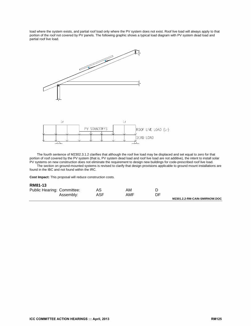
load where the system exists, and partial roof load only where the PV system does not exist. Roof live load will always apply to that portion of the roof not covered by PV panels. The following graphic shows a typical load diagram with PV system dead load and partial roof live load.
The fourth sentence of M2302.3.1.2 clarifies that although the roof live load may be displaced and set equal to zero for that
portion of roof covered by the PV system (that is, PV system dead load and roof live load are not additive), the intent to install solar PV systems on new construction does not eliminate the requirement to design new buildings for code-prescribed roof live load.
The section on ground-mounted systems is revised to clarify that design provisions applicable to ground mount installations are found in the IBC and not found within the IRC. Cost Impact: This proposal will reduce construction costs. RM81-13 Public Hearing: Committee: AS AM D Assembly: ASF AMF DF
M2301.2.2-RM-CAIN-SMIRNOW.DOC
ICC COMMITTEE ACTION HEARINGS ::: April, 2013 RM125
RM82 – 13 R202, M2301.2.3, Chapter 44 Proponents: David Hall, Vice Chair, Plumbing/Mechanical/Gas Code Action Committee, ([email protected]) and Brenda A. Thompson, Clark County Building Department, Las Vegas NV, Chair, Sustainability, Energy & High Performance Code Action Committee ([email protected]) Add new definitions as follows:
SECTION R202 DEFINITIONS
DIRECT SYSTEM. A solar thermal system in which the gas or liquid in the solar collector loop is not separated from the load. INDIRECT SYSTEM. A solar thermal system in which the gas or liquid in the solar collector loop circulates between the solar collector and a heat exchanger and such gas or liquid is not drained from the system or supplied to the load during normal operation. Revise as follows: M2301.2.3 Relief valves and system components. System components containing fluids shall be protected with temperature and pressure and temperature relief valves or pressure relief valves. Relief devices shall be installed in sections of the system so that a section cannot be valved off or isolated from a relief device. Direct systems and the potable water portion of indirect systems shall be equipped with a relief valve in accordance with Section P2803, For indirect systems, pressure relief valves in solar loops shall comply with SRCC 300. System components shall have a working pressure rating of not less than the setting of the pressure relief device. Add new standard to Chapter 44 as follows: SRCC Solar Rating & Certification Corporation 400 High Point Drive, Suite 400 Cocoa, Florida 32926 SRCC 300-13 Standard 300 For Solar Water Heating Systems Reason: This proposal is submitted by the ICC Plumbing, Mechanical and Fuel Gas Code Action Committee (PMGCAC) and the ICC Sustainability Energy and High Performance Code Action Committee (SEHPCAC). The PMGCAC and SEHPCAC were established by the ICC Board of Directors to pursue opportunities to improve and enhance assigned International Codes or portions thereof. This includes both the technical aspects of the codes as well as the code content in terms of scope and application of referenced standards. Since their inception in July, 2011, the PMGCAC and SEHPCAC have held multiple open meetings and conference calls and workgroup calls which included members of the PMGCAC and SEHPCAC. Interested parties also participated in all of the meetings and conference calls to discuss and debate the proposed changes.
This proposal revises existing Section M2301.2.3 or the 2012 IRC based on criteria in the New York State Field Inspection Guidelines for Solar Heating Systems. It clarifies when temperature and pressure relief valves or pressure relief valves are required and refers to Section P2803 and SRCC 300 for additional requirements. It also requires that system components have a pressure rating that is not less than that of the setting of the pressure relief device.
Please note that the proponents have also submitted other proposals that are coordinated with this proposal. In the spirit of the IRC as a one stop code for one- and two-family dwellings and townhouses, these proposals enhance, update, clarify and improve the usability of the solar energy provisions of Chapter 23 of the IRC and make it truly comprehensive and much more direct and intuitive. This proposal, however, is intended to stand alone and is not contingent upon the success of other PMGCAC or SEHPCAC proposals. Cost Impact: Where solar systems are provided, this proposal may increase the cost of construction.
ICC COMMITTEE ACTION HEARINGS ::: April, 2013 RM126
Analysis: A review of the standard proposed for inclusion in the code, [SRCC 300-13] with regard to the ICC criteria for referenced standards (Section 3.6 of CP#28), will be posted on the ICC website on or before April 1, 2013. RM82-13 Public Hearing: Committee: AS AM D Assembly: ASF AMF DF
M2301.2.3-RM-HALL-THOMPSON-SEPHCAC.DOC
ICC COMMITTEE ACTION HEARINGS ::: April, 2013 RM127
RM83 – 13 M2301.2.3 (New) Proponents: David Hall, Vice Chair, Plumbing/Mechanical/Gas Code Action Committee, ([email protected]) and Brenda A. Thompson, Clark County Building Department, Las Vegas NV, Chair, Sustainability, Energy & High Performance Code Action Committee ([email protected]) Add new text as follows: M2301.2.3 Plastic glazing. The use of plastic glazing in solar thermal collectors and panels shall be limited to those plastics meeting the requirements for light transmitting plastics in Chapter 26 of the International Building Code. Reason: This proposal is submitted by the ICC Plumbing, Mechanical and Fuel Gas Code Action Committee (PMGCAC) and the ICC Sustainability Energy and High Performance Code Action Committee (SEHPCAC). The PMGCAC and SEHPCAC were established by the ICC Board of Directors to pursue opportunities to improve and enhance assigned International Codes or portions thereof. This includes both the technical aspects of the codes as well as the code content in terms of scope and application of referenced standards. Since their inception in July, 2011, the PMGCAC and SEHPCAC have held multiple open meetings and conference calls and workgroup calls which included members of the PMGCAC and SEHPCAC. Interested parties also participated in all of the meetings and conference calls to discuss and debate the proposed changes.
Reasons for this proposal are as follows: The language in the proposed new section is similar to the exception to Section 1402.4, Roof-mounted collectors, of the 2012
International Mechanical Code. This language is necessary to properly address plastic solar collector covers, which are essentially prohibited by the 2012 IRC, but are not prohibited by 2012 International Mechanical Code.
Please note that the proponents have also submitted other proposals that are coordinated with this proposal. In the spirit of the IRC as a one stop code for one- and two-family dwellings and townhouses, these proposals enhance, update, clarify and improve the usability of the solar energy provisions of Chapter 23 of the IRC and make it truly comprehensive and much more direct and intuitive. This proposal, however, is intended to stand alone and is not contingent upon the success of other PMGCAC or SEHPCAC proposals. Cost Impact: Where solar systems are provided, this proposal may increase the cost of construction. RM83-13 Public Hearing: Committee: AS AM D Assembly: ASF AMF DF
M2301.2.3 (NEW)-RM-HALL-THOMPSON-SEHPCAC.DOC
ICC COMMITTEE ACTION HEARINGS ::: April, 2013 RM128
RM84 – 13 M2301.2.5 (New) Proponent: David Hall, Vice Chair, Plumbing/Mechanical/Gas Code Action Committee, ([email protected]) and Brenda A. Thompson, Clark County Building Department, Las Vegas NV, Chair, Sustainability, Energy & High Performance Code Action Committee ([email protected]) Add new text as follows: M2301.2.5 Piping insulation. Piping shall be insulated in accordance with the requirements of Chapter 11. Exterior insulation shall be protected from ultraviolet degradation. The entire solar loop shall be insulated. Where split-style insulation is used, the seam shall be sealed. Fittings shall be fully insulated.
Exceptions:
1. Those portions of the piping that are used to help prevent the system from overheating shall not be required to be insulated.
2. Those portions of piping that are exposed to solar radiation, made of the same material as the solar collector absorber plate and are covered in the same manner as the solar collector absorber, or that are used to collect additional solar energy shall not be required to be insulated
3. Piping in thermal solar systems using unglazed solar collectors to heat a swimming pool shall not be required to be insulated.
Reason: This proposal is submitted by the ICC Plumbing, Mechanical and Fuel Gas Code Action Committee (PMGCAC) and the ICC Sustainability Energy and High Performance Code Action Committee (SEHPCAC). The PMGCAC and SEHPCAC were established by the ICC Board of Directors to pursue opportunities to improve and enhance assigned International Codes or portions thereof. This includes both the technical aspects of the codes as well as the code content in terms of scope and application of referenced standards. Since their inception in July, 2011, the PMGCAC and SEHPCAC have held multiple open meetings and conference calls and workgroup calls which included members of the PMGCAC and SEHPCAC. Interested parties also participated in all of the meetings and conference calls to discuss and debate the proposed changes.
This proposal adds new requirements for piping insulation used in solar systems to the thermal solar provisions of the 2012 IRC. It is based on criteria in the New York State Field Inspection Guidelines for Solar (thermal) Heating Systems.
Please note that the proponents have also submitted other proposals that are coordinated with this proposal. In the spirit of the IRC as a one stop code for one- and two-family dwellings and townhouses, these proposals enhance, update, clarify and improve the usability of the solar energy provisions of Chapter 23 of the IRC and make it truly comprehensive and much more direct and intuitive. This proposal, however, is intended to stand alone and is not contingent upon the success of other PMGCAC or SEHPCAC proposals. Cost Impact: Where solar systems are provided, this proposal may increase the cost of construction. RM84-13 Public Hearing: Committee: AS AM D Assembly: ASF AMF DF
M2301.2.5 (NEW)-RM-HALL-THOMPSON-SEPHCAC.DOC
ICC COMMITTEE ACTION HEARINGS ::: April, 2013 RM129
RM85 – 13 Section R202, M2301.2.6, Chapter 44 Proponents: David Hall, Vice Chair, Plumbing/Mechanical/Gas Code Action Committee, ([email protected]) and Brenda A. Thompson, Clark County Building Department, Las Vegas NV, Chair, Sustainability, Energy & High Performance Code Action Committee ([email protected]) Add new definition as follows: DRAIN-BACK SYSTEM. A solar thermal system in which the fluid in the solar collector loop is drained from the collector into a holding tank under prescribed circumstances. Revise as follows: M2301.2.6 Expansion tanks. Expansion tanks in solar energy systems shall be installed in accordance with Section M2003 in closed fluid solar collector loops that contain pressurized heat transfer fluid. Where expansion tanks are used, the system shall be designed in accordance with SRCC 300 to provide an expansion tank that is sized to withstand the maximum operating pressure of the system.
Exception: Expansion tanks shall not be required in drain-back systems. Add new standard to Chapter 44 as follows: SRCC Solar Rating & Certification Corporation 400 High Point Drive, Suite 400 Cocoa, Florida 32926
SRCC 300-13 Standard 300 For Solar Water Heating Systems Reason: This proposal is submitted by the ICC Plumbing, Mechanical and Fuel Gas Code Action Committee (PMGCAC) and the ICC Sustainability Energy and High Performance Code Action Committee (SEHPCAC). The PMGCAC and SEHPCAC were established by the ICC Board of Directors to pursue opportunities to improve and enhance assigned International Codes or portions thereof. This includes both the technical aspects of the codes as well as the code content in terms of scope and application of referenced standards. Since their inception in July, 2011, the PMGCAC and SEHPCAC have held multiple open meetings and conference calls and workgroup calls which included members of the PMGCAC and SEHPCAC. Interested parties also participated in all of the meetings and conference calls to discuss and debate the proposed changes.
This proposal revises existing Section M2301.2.6 of the 2012 IRC based on criteria in the New York State Field Inspection Guidelines for Solar Heating Systems that reference SRCC 300 and are applicable to solar thermal systems.
Please note that the proponents have also submitted other proposals that are coordinated with this proposal. In the spirit of the IRC as a one stop code for one- and two-family dwellings and townhouses, these proposals enhance, update, clarify and improve the usability of the solar energy provisions of Chapter 23 of the IRC and make it truly comprehensive and much more direct and intuitive. This proposal, however, is intended to stand alone and is not contingent upon the success of other PMGCAC or SEHPCAC proposals. Cost Impact: Where solar systems are provided, this proposal may increase the cost of construction. Analysis: A review of the standard proposed for inclusion in the code, [SRCC 300-13] with regard to the ICC criteria for referenced standards (Section 3.6 of CP#28), will be posted on the ICC website on or before April 1, 2013. RM85-13 Public Hearing: Committee: AS AM D Assembly: ASF AMF DF
M2301.2.6-RM-HALL-THOMPSON-SEPHCAC.DOC
ICC COMMITTEE ACTION HEARINGS ::: April, 2013 RM130
RM86 – 13 M2301.2.6 (New), Chapter 44 Proponents: David Hall, Vice Chair, Plumbing/Mechanical/Gas Code Action Committee, ([email protected]) and Brenda A. Thompson, Clark County Building Department, Las Vegas NV, Chair, Sustainability, Energy & High Performance Code Action Committee ([email protected]) Add new text as follows: M2301.2.6 Storage tank sensors. Storage tank sensors shall comply with SRCC 300. Add new standard to Chapter 44 as follows: SRCC Solar Rating & Certification Corporation 400 High Point Drive, Suite 400 Cocoa, Florida 32926
SRCC 300-13 Standard 300 For Solar Water Heating Systems Reason: This proposal is submitted by the ICC Plumbing, Mechanical and Fuel Gas Code Action Committee (PMGCAC) and the ICC Sustainability Energy and High Performance Code Action Committee (SEHPCAC). The PMGCAC and SEHPCAC were established by the ICC Board of Directors to pursue opportunities to improve and enhance assigned International Codes or portions thereof. This includes both the technical aspects of the codes as well as the code content in terms of scope and application of referenced standards. Since their inception in July, 2011, the PMGCAC and SEHPCAC have held multiple open meetings and conference calls and workgroup calls which included members of the PMGCAC and SEHPCAC. Interested parties also participated in all of the meetings and conference calls to discuss and debate the proposed changes.
This proposal is based on criteria in the New York State Field Inspection Guidelines for Solar Heating Systems that are relative to storage tank sensors.
Please note that the proponents have also submitted other proposals that are coordinated with this proposal. In the spirit of the IRC as a one stop code for one- and two-family dwellings and townhouses, these proposals enhance, update, clarify and improve the usability of the solar energy provisions of Chapter 23 of the IRC and make it truly comprehensive and much more direct and intuitive. This proposal, however, is intended to stand alone and is not contingent upon the success of other PMGCAC or SEHPCAC proposals. Cost Impact: Where solar systems are provided, this proposal may increase the cost of construction Analysis: A review of the standard proposed for inclusion in the code, [SRCC 300-13] with regard to the ICC criteria for referenced standards (Section 3.6 of CP#28) will be posted on the ICC website on or before April 1, 2013. RM86-13 Public Hearing: Committee: AS AM D Assembly: ASF AMF DF
M2301.2.6 (NEW) #1-RM-HALL-THOMPSON-SEPHCAC.DOC
ICC COMMITTEE ACTION HEARINGS ::: April, 2013 RM131
RM87 – 13 M2301.2.6 (New), M2301.2.7 (New) Proponents: David Hall, Vice Chair, Plumbing/Mechanical/Gas Code Action Committee, ([email protected]) and Brenda A. Thompson, Clark County Building Department, Las Vegas NV, Chair, Sustainability, Energy & High Performance Code Action Committee ([email protected]) Add new text as follows: M2301.2.6 Mixing valves. Where heated water is discharged from a solar thermal system to a hot water distribution system, a thermostatic mixing valve complying with ASSE 1017 shall be installed to temper the water to a temperature of not greater than 140oF. Solar thermal systems supplying hot water for both space heating and domestic uses shall comply with Section P2802.2. A temperature indicating device shall be installed to indicate the temperature of the water discharged from the outlet of the mixing valve. The thermostatic mixing valve required by this section shall not be a substitute for water temperature limiting devices required by Chapter 27 for specific fixtures. M2301.2.7 Isolation valves. Isolation valves shall be provided on the cold water feed to the water heater. Isolation valves and associated piping shall be provided to bypass solar storage tanks where the system contains multiple storage tanks. Reason: This proposal is submitted by the ICC Plumbing, Mechanical and Fuel Gas Code Action Committee (PMGCAC) and the ICC Sustainability Energy and High Performance Code Action Committee (SEHPCAC). The PMGCAC and SEHPCAC were established by the ICC Board of Directors to pursue opportunities to improve and enhance assigned International Codes or portions thereof. This includes both the technical aspects of the codes as well as the code content in terms of scope and application of referenced standards. Since their inception in July, 2011, the PMGCAC and SEHPCAC have held multiple open meetings and conference calls and workgroup calls which included members of the PMGCAC and SEHPCAC. Interested parties also participated in all of the meetings and conference calls to discuss and debate the proposed changes.
These proposed new sections address mixing valves and isolation valves in solar thermal systems. They are based on Section P2803.3 of the 2012 IRC and criteria in the New York State Field Inspection Guidelines for Solar (thermal) Heating Systems.
Please note that the proponents have also submitted other proposals that are coordinated with this proposal. In the spirit of the IRC as a one stop code for one- and two-family dwellings and townhouses, these proposals enhance, update, clarify and improve the usability of the solar energy provisions of Chapter 23 of the IRC and make it truly comprehensive and much more direct and intuitive. This proposal, however, is intended to stand alone and is not contingent upon the success of other PMGCAC or SEHPCAC proposals. Cost Impact: Where solar systems are provided, this proposal may increase the cost of construction. RM87-13 Public Hearing: Committee: AS AM D Assembly: ASF AMF DF
M2301.2.6 (NEW) #2-RM-HALL-THOMPSON-SEPHCAC.DOC
ICC COMMITTEE ACTION HEARINGS ::: April, 2013 RM132
RM88 – 13 M2301.2.8 (New), M2301.2.9 (New), M2301.9.1, M2301.2.9.2 (New), Chapter 44 Proponents: David Hall, Vice Chair, Plumbing/Mechanical/Gas Code Action Committee, ([email protected]) and Brenda A. Thompson, Clark County Building Department, Las Vegas NV, Chair, Sustainability, Energy & High Performance Code Action Committee ([email protected]) Revise as follows: M2301.2.8 Description and warning labels. Solar thermal systems shall comply with description label and warning label requirements of Section M2301.2.9.2 and SRCC 300. M2301.2.9 Solar loop. Solar loops shall be in accordance with Sections M2301.2.8.1 and M2301.2.8.2. M2301.9.1 M2301.2.8 Solar loop isolation. Valves shall be installed to allow the solar collectors to be isolated from the remainder of the system. Each isolation valve shall be labeled with the open and closed position. M2301.2.9.2 Drain and fill valve labels and caps. Drain and fill valves shall be labeled with a description and warning that identifies the fluid in the solar loop and a warning that the fluid might be discharged at high temperature and pressure. Drain caps shall be installed at drain and fill valves. Add new standard to Chapter 44 as follows: SRCC Solar Rating & Certification Corporation 400 High Point Drive, Suite 400 Cocoa, Florida 32926
SRCC 300-13 Standard 300 For Solar Water Heating Systems Reason: This proposal is submitted by the ICC Plumbing, Mechanical and Fuel Gas Code Action Committee (PMGCAC) and the ICC Sustainability Energy and High Performance Code Action Committee (SEHPCAC). The PMGCAC and SEHPCAC were established by the ICC Board of Directors to pursue opportunities to improve and enhance assigned International Codes or portions thereof. This includes both the technical aspects of the codes as well as the code content in terms of scope and application of referenced standards. Since their inception in July, 2011, the PMGCAC and SEHPCAC have held multiple open meetings and conference calls and workgroup calls which included members of the PMGCAC and SEHPCAC. Interested parties also participated in all of the meetings and conference calls to discuss and debate the proposed changes.
This proposal expands existing Section M2301.2.8 of the 2012 IRC, which pertains to solar loops, and adds a new section to the solar thermal provisions of the IRC. These changes are based on criteria in the New York State Field Inspection Guidelines for Solar (thermal) Heating Systems.
Proposed new Section M2301.2.8 references SRCC 300 for label, sigh and marking requirements. (These are not listing and labeling requirements that require third party testing. These labels identify system components and provide safety warnings.
SRCC 300 Includes references to labeling requirements under:
6.1.1.2 Solar Systems Isolation 6.1.1.4 Auxiliary Water Heating Equipment 6.2.5 Freeze Protection 6.1.5.2 Control System Override 6.3.7 Fluid Safety Labeling 6.4.3 Tanks
SRCC 300 includes references to warning label requirements:
6.3.17 Heated Components (warning label) 6.6.7 Hazards (warning label)
Section M2309.1, former Section M2301.2.8, is revised to eliminate redundant labeling requirements with the SRCC 300 reference added in proposed new Section M2301.2.8.
ICC COMMITTEE ACTION HEARINGS ::: April, 2013 RM133
Proposed new Section M2301.9.2 specifically addresses drain and fill valve labels and caps. These changes are based on criteria in the New York State Field Inspection Guidelines for Solar (thermal) Heating Systems
and the manner in which it references SRCC 300. Please note that the proponents have also submitted other proposals that are coordinated with this proposal. In the spirit of the
IRC as a one stop code for one- and two-family dwellings and townhouses, these proposals enhance, update, clarify and improve the usability of the solar energy provisions of Chapter 23 of the IRC and make it truly comprehensive and much more direct and intuitive. This proposal, however, is intended to stand alone and is not contingent upon the success of other PMGCAC or SEHPCAC proposals. Cost Impact: Where solar systems are provided, this proposal may increase the cost of construction. Analysis: A review of the standard proposed for inclusion in the code, [SRCC 300-13] with regard to the ICC criteria for referenced standards (Section 3.6 of CP#28), will be posted on the ICC website on or before April 1, 2013. RM88-13 Public Hearing: Committee: AS AM D Assembly: ASF AMF DF
M2301.2.8 (NEW)-HALL-THOMPSON-SEHPCAC.DOC
ICC COMMITTEE ACTION HEARINGS ::: April, 2013 RM134
RM89 – 13 M2301.3.1, Chapter 44 Proponents: David Hall, Vice Chair, Plumbing/Mechanical/Gas Code Action Committee([email protected]) and Brenda A. Thompson, Clark County Building Department, Las Vegas NV, Chair, Sustainability, Energy & High Performance Code Action Committee ([email protected]) Revise as follows: M2301.3.1 Collectors and panels. Solar thermal collectors and panels shall be listed and labeled in accordance with SRCC 100 or SRCC 600. Collectors and panels shall be listed and labeled to show the manufacturer’s name, model number, serial number, collector weight, collector maximum allowable temperatures and pressures, and the type of heat transfer fluids that are compatible with the collector or panel. The label shall clarify that these specifications apply only to the collector or panel. Add new standards to Chapter 44 as follows: SRCC Solar Rating & Certification Corporation 400 High Point Drive, Suite 400 Cocoa, Florida 32926
SRCC 100-13 Standard 100 For Solar Collectors SRCC 600-13 Standard 600 For Solar Concentrating Collectors Reason: This proposal is submitted by the ICC Plumbing, Mechanical and Fuel Gas Code Action Committee (PMGCAC) and the ICC Sustainability Energy and High Performance Code Action Committee (SEHPCAC). The PMGCAC and SEHPCAC were established by the ICC Board of Directors to pursue opportunities to improve and enhance assigned International Codes or portions thereof. This includes both the technical aspects of the codes as well as the code content in terms of scope and application of referenced standards. Since their inception in July, 2011, the PMGCAC and SEHPCAC have held multiple open meetings and conference calls and workgroup calls which included members of the PMGCAC and SEHPCAC. Interested parties also participated in all of the meetings and conference calls to discuss and debate the proposed changes.
This proposal revises existing Section M2301.3.1 of the 2012 IRC to require that solar thermal system collectors and panels be listed and labeled in accordance with the requirements of SRCC 100 or SRCC 600.
These revisions are based on criteria in the New York State Field Inspection Guidelines for Solar Heating Systems and the manner in which it addresses the SRCC standards.
This proposal is intended to stand alone and is not contingent upon the success of other proposals from the PMGCAC and SEHPCAC related to solar energy,
Please note that the proponents have also submitted other proposals that are coordinated with this proposal. In the spirit of the IRC as a one stop code for one- and two-family dwellings and townhouses, these proposals enhance, update, clarify and improve the usability of the solar energy provisions of Chapter 23 of the IRC and make it truly comprehensive and much more direct and intuitive. Cost Impact: Where solar systems are provided, this proposal may increase the cost of construction. Analysis: A review of the standards proposed for inclusion in the code, [SRCC 100-13 and 600-13] with regard to the ICC criteria for referenced standards (Section 3.6 of CP#28), will be posted on the ICC website on or before April 1, 2013. RM89-13 Public Hearing: Committee: AS AM D Assembly: ASF AMF DF
M2301.3.1-RM-HALL-THOMPSON-SEHPCAC.DOC
ICC COMMITTEE ACTION HEARINGS ::: April, 2013 RM135
RM90 – 13 Section M2301.4, Chapter 44 Proponents: David Hall, Vice Chair, Plumbing/Mechanical/Gas Code Action Committee, ([email protected]) and Brenda A. Thompson, Clark County Building Department, Las Vegas NV, Chair, Sustainability, Energy & High Performance Code Action Committee ([email protected]) Revise as follows: M2301.4 Heat transfer gasses or liquids and heat exchangers. Prohibited heat transfer fluids. Flammable gases and liquids shall not be used as heat transfer fluids. Heat transfer gasses and liquids shall be rated to withstand the system’s maximum design temperature under operating conditions without degradation. Heat exchangers used in solar thermal systems shall comply with Section P2902.5.2 and SRCC 300. Add new standard to Chapter 44 as follows: SRCC Solar Rating & Certification Corporation 400 High Point Drive, Suite 400 Cocoa, Florida 32926
SRCC 300-13 Standard 300 For Solar Water Heating Systems Reason: This proposal is submitted by the ICC Plumbing, Mechanical and Fuel Gas Code Action Committee (PMGCAC) and the ICC Sustainability Energy and High Performance Code Action Committee (SEHPCAC). The PMGCAC and SEHPCAC were established by the ICC Board of Directors to pursue opportunities to improve and enhance assigned International Codes or portions thereof. This includes both the technical aspects of the codes as well as the code content in terms of scope and application of referenced standards. Since their inception in July, 2011, the PMGCAC and SEHPCAC have held multiple open meetings and conference calls and workgroup calls which included members of the PMGCAC and SEHPCAC. Interested parties also participated in all of the meetings and conference calls to discuss and debate the proposed changes.
This proposal revises existing Section M2301.4 of the 2012 IRC based on criteria in the New York State Field Inspection Guidelines for Solar (thermal) Heating Systems.
Please note that the proponents have also submitted other proposals that are coordinated with this proposal. In the spirit of the IRC as a one stop code for one- and two-family dwellings and townhouses, these proposals enhance, update, clarify and improve the usability of the solar energy provisions of Chapter 23 of the IRC and make it truly comprehensive and much more direct and intuitive. This proposal, however, is intended to stand alone and is not contingent upon the success of other PMGCAC or SEHPCAC proposals. Cost Impact: Where solar systems are provided, this proposal may increase the cost of construction. Analysis: A review of the standard proposed for inclusion in the code, [SRCC 300-13] with regard to the ICC criteria for referenced standards (Section 3.6 of CP#28), will be posted on the ICC website on or before April 1, 2013. RM90-13 Public Hearing: Committee: AS AM D Assembly: ASF AMF DF
M2301.4 #2-RM-HALL-THOMPSON-SEHPCAC.DOC
ICC COMMITTEE ACTION HEARINGS ::: April, 2013 RM136
RM91 – 13 M2301.4, Chapter 44 Proponents: David Hall, Vice Chair, Plumbing/Mechanical/Gas Code Action Committee, ([email protected]) and Brenda A. Thompson, Clark County Building Department, Las Vegas NV, Chair, Sustainability, Energy & High Performance Code Action Committee ([email protected]) Revise as follows: M2301.4 Prohibited Heat transfer fluids. Essentially toxic transfer fluids, ethylene glycol, flammable gases, and flammable liquids shall not be used as heat transfer fluids. Heat transfer fluids shall be in accordance with SRCC 300. The flash point of the heat transfer fluids utilized in solar thermal systems shall be not less than 50°F (28°C) above the design maximum non-operating or no-flow temperature attained by the fluid in the collector. Add new standard to Chapter 44 as follows: SRCC Solar Rating & Certification Corporation 400 High Point Drive, Suite 400 Cocoa, Florida 32926
SRCC 300-13 Standard 300 For Solar Water Heating Systems Reason: This proposal is submitted by the ICC Plumbing, Mechanical and Fuel Gas Code Action Committee (PMGCAC) and the ICC Sustainability Energy and High Performance Code Action Committee (SEHPCAC). The PMGCAC and SEHPCAC were established by the ICC Board of Directors to pursue opportunities to improve and enhance assigned International Codes or portions thereof. This includes both the technical aspects of the codes as well as the code content in terms of scope and application of referenced standards. Since their inception in July, 2011, the PMGCAC and SEHPCAC have held multiple open meetings and conference calls and workgroup calls which included members of the PMGCAC and SEHPCAC. Interested parties also participated in all of the meetings and conference calls to discuss and debate the proposed changes.
Reasons for this proposal are as follows: The first sentence of this proposal revises existing Section 2301.4 of the 2012 IRC to align with Section 1403, Heat Transfer Fluids, of the 2012 International Mechanical Code. It also specifically prohibits the use of ethylene glycol so as to eliminate any confusion regarding its use. The proposed new second sentence requires heat transfer fluids to be in accordance with SRCC 300. The proposed new last sentence limits the flash point of heat transfer fluids in solar thermal systems.
Please note that the proponents have also submitted other proposals that are coordinated with this proposal. In the spirit of the IRC as a one stop code for one- and two-family dwellings and townhouses, these proposals enhance, update, clarify and improve the usability of the solar energy provisions of Chapter 23 of the IRC and make it truly comprehensive and much more direct and intuitive. This proposal, however, is intended to stand alone and is not contingent upon the success of other PMGCAC or SEHPCAC proposals. Cost Impact: Where solar systems are provided, this proposal may increase the cost of construction. Analysis: A review of the standard proposed for inclusion in the code, [SRCC 300-13] with regard to the ICC criteria for referenced standards (Section 3.6 of CP#28), will be posted on the ICC website on or before April 1, 2013. RM91-13 Public Hearing: Committee: AS AM D Assembly: ASF AMF DF
M2301.4#1 RM-HALL-THOMPSON-SEHPCAC.DOC
ICC COMMITTEE ACTION HEARINGS ::: April, 2013 RM137
RM92 – 13 M2301.6 (New) Proponents: David Hall, Vice Chair, Plumbing/Mechanical/Gas Code Action Committee, ([email protected]) and Brenda A. Thompson, Clark County Building Department, Las Vegas NV, Chair, Sustainability, Energy & High Performance Code Action Committee ([email protected]) Add new text as follows: M2301.6 Filtering. Air provided to occupied spaces through rock or other dust-producing materials shall be filtered for particulates at the outlet of the heat storage system.
Exception: Filters shall not be required where air movement is by means of natural convection. Reason: This proposal is submitted by the ICC Plumbing, Mechanical and Fuel Gas Code Action Committee (PMGCAC) and the ICC Sustainability Energy and High Performance Code Action Committee (SEHPCAC). The PMGCAC and SEHPCAC were established by the ICC Board of Directors to pursue opportunities to improve and enhance assigned International Codes or portions thereof. This includes both the technical aspects of the codes as well as the code content in terms of scope and application of referenced standards. Since their inception in July, 2011, the PMGCAC and SEHPCAC have held multiple open meetings and conference calls and workgroup calls which included members of the PMGCAC and SEHPCAC. Interested parties also participated in all of the meetings and conference calls to discuss and debate the proposed changes.
Reasons for this proposal are as follows: This proposed new section is similar to Section 1402.7 of the 2012 International Mechanical Code. It requires filtering in order to remove dust and particulates from mechanically forced air that has passed through a thermal storage area containing materials such as, but not limited to, pebbles or rock. A filter is not required for passive systems because the air velocity is typically not sufficient to carry particulates. Furthermore, a filter in a passive system could greatly impede natural convective airflow.
Please note that the proponents have also submitted other proposals that are coordinated with this proposal. In the spirit of the IRC as a one stop code for one- and two-family dwellings and townhouses, these proposals enhance, update, clarify and improve the usability of the solar energy provisions of Chapter 23 of the IRC and make it truly comprehensive and much more direct and intuitive. This proposal, however, is intended to stand alone and is not contingent upon the success of other PMGCAC or SEHPCAC proposals. Cost Impact: Where rock based or dust-producing heat storage systems are provided, this proposal may increase the cost of construction. RM92-13 Public Hearing: Committee: AS AM D Assembly: ASF AMF DF
M2301.6 (NEW) #1-RM-HALL-THOMPSON-SEHPCAC.DOC
ICC COMMITTEE ACTION HEARINGS ::: April, 2013 RM138
RM93 – 13 M2301.6 (New), M2301.6.1 (New), M2301.6.2 (New), P2902.5.5 Proponents: David Hall, Vice Chair, Plumbing/Mechanical/Gas Code Action Committee, ([email protected]) and Brenda A. Thompson, Clark County Building Department, Las Vegas NV, Chair, Sustainability, Energy & High Performance Code Action Committee ([email protected]) Add new text as follows: M2301.6 Solar systems for heating potable water. Where a solar energy system heats potable water to supply a potable hot water distribution system, the solar energy system shall be in accordance with Sections M2301.6.1, M2301.6.2 and P2902.5.5. M2301.6.1 Indirect systems. Heat exchangers that are components of indirect heating systems shall comply with Section P2902.5.2.
M2301.6.2 Direct systems. Where potable water is directly heated, the pipe, fittings and valves between the solar collectors and the hot water storage tanks shall comply with NSF 61. Revise as follows: P2902.5.5 Solar systems. The potable water supply to a solar system shall be equipped with a backflow preventer with intermediate atmospheric vent complying with ASSE 1012 or a reduced pressure principle backflow preventer complying with ASSE 1013. Where chemicals are used, the potable water supply shall be protected by a reduced pressure principle backflow preventer. Where a potable water supply is connected to the solar collector circulation loop piping of an indirect solar water heating system and chemicals are not used in the circulation loop piping, a backflow preventer in accordance with ASSE 1012 shall be installed between the potable water system and the circulation loop piping. Where chemicals are used in the solar collector circulation loop piping, such backflow preventer shall be in accordance with ASSE 1013.
Exception: Where all solar system piping is a part of the potable water distribution system, in accordance with the requirements of the International Plumbing Code, and all components of the piping system are listed for potable water use, cross-connection protection measures shall not be required.
Reason: This proposal is submitted by the ICC Plumbing, Mechanical and Fuel Gas Code Action Committee (PMGCAC) and the ICC Sustainability Energy and High Performance Code Action Committee (SEHPCAC). The PMGCAC and SEHPCAC were established by the ICC Board of Directors to pursue opportunities to improve and enhance assigned International Codes or portions thereof. This includes both the technical aspects of the codes as well as the code content in terms of scope and application of referenced standards. Since their inception in July, 2011, the PMGCAC and SEHPCAC have held multiple open meetings and conference calls and workgroup calls which included members of the PMGCAC and SEHPCAC. Interested parties also participated in all of the meetings and conference calls to discuss and debate the proposed changes.
Reasons for this proposal are as follows: Chapter 23 should include Sections M2301.6, M2301.6.1 and M2301.6.2 in order to address specific requirements for solar energy systems where they are used to heat potable water for supply to a potable hot water distribution system. Section M2301.6.1 is a pointer to a section that covers heat exchangers in the plumbing code section of the IRC:
P2902.5.2 Heat exchangers. Heat exchangers using an essentially toxic transfer fluid shall be separated from the potable water by double-wall construction. An air gap open to the atmosphere shall be provided between the two walls. Heat exchangers utilizing an essentially nontoxic transfer fluid shall be permitted to be of single-wall construction.
This section would apply where potable water was indirectly heated by the solar energy system. Section M2301.6.2 requires NSF 61 compliance for pipe, fittings and valves in a system that directly heats potable water as this is the same requirement for pipe, fittings and valves that the plumbing code requires for the hot water distribution system.
Section P2902.5.5 is modified as the section has been unclear for many cycles. Some have interpreted the existing section to require a backflow preventer on the cold water supply to any water heater that has a solar energy water heating system connected to the water heater. This makes no sense for a system that directly heats the water for distribution to the potable hot water distribution system. The section is modified to make the language address where the backflow preventer is needed (only for connections to solar collector circulation loop piping of indirect heating systems).
Please note that the proponents have also submitted other proposals that are coordinated with this proposal. In the spirit of the IRC as a one stop code for one- and two-family dwellings and townhouses, these proposals enhance, update, clarify and improve
ICC COMMITTEE ACTION HEARINGS ::: April, 2013 RM139
the usability of the solar energy provisions of Chapter 23 of the IRC and make it truly comprehensive and much more direct and intuitive. This proposal, however, is intended to stand alone and is not contingent upon the success of other PMGCAC or SEHPCAC proposals. Cost Impact: Where solar water heating systems are provided, this proposal may increase the cost of construction. RM93-13 Public Hearing: Committee: AS AM D Assembly: ASF AMF DF
2301.6 (NEW) #2-RM-HALL-THOMPSON-SEPHCAC.DOC
ICC COMMITTEE ACTION HEARINGS ::: April, 2013 RM140
RM94 – 13 Sections M2302.2, M2302.2.3, M2302.5 (New), M2302.6 (New), M2302.7 (New),), M2302.6.1 (New), M2302.6.2 (New), M2302.6.3 (New), M2302.6.4 (New), M2302.6.5 (New) Proponents: David Hall, Vice Chair, Plumbing/Mechanical/Gas Code Action Committee, ([email protected]) and Brenda A. Thompson, Clark County Building Department, Las Vegas NV, Chair, Sustainability, Energy & High Performance Code Action Committee; Adolf Zubia, Chair, Fire Code Action Committee ([email protected]) Revise as follows: M2302.2 Requirements. The installation, inspection, maintenance, repair and replacement of photovoltaic systems and all system components shall comply with the manufacturer’s instructions, Sections M2302.2.1 through M2302.2.3 M2302.7 and NFPA 70. M2302.7 M2302.2.3 Ground-mounted photovoltaic panel systems and modules. Ground-mounted photovoltaic panel systems shall be installed in accordance with the manufacturer’s instructions. Fire separation distance requirements shall not apply to ground-mounted, free-standing photovoltaic arrays. A clear, brush-free area of 10 feet (3048 mm) shall be required for ground-mounted photovoltaic arrays. M2302.5 Size of solar photovoltaic array. Each photovoltaic array shall be not greater than 150 feet (45 720 mm) by 150 feet (45 720 mm). Multiple arrays shall be separated by a clear access pathway not less than 3-feet (914 mm) in width. M2302.6 Access and pathways. Roof access, pathways, and spacing requirements shall be provided in accordance with this section and Sections M2302.6.1 through M2302.6.5.
Exception: Detached garages and accessory structures to one- and two-family dwellings and townhouses such as parking shade structures, carports, solar trellises and similar structures.
M2302.6.1 Roof access points. Roof access points shall be located in areas where it will not be necessary to place ground ladders over openings such as windows or doors, and shall be located at strong points of building construction in locations where the access point does not conflict with overhead obstructions such as tree limbs, wires and signs. M2302.6.2 Hip roof layouts. Panels and modules installed on residential buildings with hip roof layouts shall be located in a manner that provides two clear access pathways not less than 3-feet (914 mm) in width from the eave to the ridge on each roof slope where panels and modules are located. The access pathways shall be located in areas where the building is capable of supporting the live load of fire fighters accessing the roof.
Exception: These requirements shall not apply to roofs with slopes of two units vertical in 12 units horizontal (2:12) or less.
M2302.6.3 Single ridge roofs. Panels and modules installed on buildings with a single ridge shall be located in a manner that provides two access pathways not less than 3 feet (914mm) in width from the eave to the ridge on each roof slope where panels and modules are located.
Exception: This requirement shall not apply to roofs with slopes of two units vertical in 12 units horizontal (2:12) or less.
ICC COMMITTEE ACTION HEARINGS ::: April, 2013 RM141
M2302.6.4 Roofs with hips and valleys. Panels and modules installed on buildings with roof hips and valleys shall not be located within 18 inches (457 mm) of a hip or a valley where panels or modules are placed on both sides of the hip or valley.
Exception: These requirements shall not apply to roofs with slopes of two units vertical in 12 units horizontal (2:12) or less.
M2302.6.5 Allowance for smoke ventilation operations. Panels and modules installed on buildings shall not be located within 3 feet (914 mm) of the ridge to allow for fire department smoke ventilation operations.
Exception: Where an alternative ventilation method approved by the building official has been provided or where the building official has determined that vertical ventilation techniques will not be employed.
Reason: This proposal is submitted by the ICC Plumbing, Mechanical and Fuel Gas Code Action Committee (PMGCAC), the ICC Sustainability Energy and High Performance Code Action Committee (SEHPCAC) and the ICC Fire Code Action Committee (FCAC). The PMGCAC, SEHPCAC and FCAC were established by the ICC Board of Directors to pursue opportunities to improve and enhance assigned International Codes or portions thereof. This includes both the technical aspects of the codes as well as the code content in terms of scope and application of referenced standards. The PMGCAC, SEHPCAC and FCAC have held multiple open meetings and conference calls and workgroup calls which included members of the PMGCAC, SEHPCAC and FCAC, respectively. Interested parties also participated in all of the meetings and conference calls to discuss and debate the proposed changes.
Reasons for this proposal are as follows: This proposal imports all of the criteria that is applicable to IRC buildings from Section 605.11 of the International Fire Code (Solar photovoltaic power systems) and its subsections.
This proposal does not address “electrical requirements,’ though it may require markings on some electrical components that are utilized a solar system. The only “electrical” requirement in Chapter 23 is the requirement to comply with NFPA 70 in existing Section M2302.1 of the 2012 IRC.
Please note that the proponents have also submitted other proposals that are coordinated with this proposal. In the spirit of the IRC as a one stop code for one- and two-family dwellings and townhouses, these proposals enhance, update, clarify and improve the usability of the solar energy provisions of Chapter 23 of the IRC and make it truly comprehensive and much more direct and intuitive. This proposal, however, is intended to stand alone and is not contingent upon the success of other PMGCAC or SEHPCAC proposals. Cost Impact: Where photovoltaic solar systems are provided, this proposal may increase the cost of construction. RM94-13 Public Hearing: Committee: AS AM D Assembly: ASF AMF DF
M2302.2-RM-HALL-THOMPSON-SEHPCAC.DOC
ICC COMMITTEE ACTION HEARINGS ::: April, 2013 RM142
RM95 – 13 M2302.2, M2302.2.1, M2302.2.2 thru M2302.2.2s.2.5 (New), M2302.2.2 thru M2302.4 Proponent: Adria Smith, Fountain Valley Fire Department, Representing the California Fire Chiefs Association; Kevin Reinertson, Division Chief, Representing the California State Fire Marshal’s Office ([email protected]) Revise as follows: M2302.2 Requirements. The installation, inspection, maintenance, repair and replacement of photovoltaic systems and all system components shall comply with the manufacturer’s instructions, Sections M2302.21 through M2302.2.3 M2302.2.7 and NFPA 70. M2302.2.1 Roof-mounted panels and modules. Where photovoltaic panels and modules are installed on roofs, the roof shall be constructed to support the loads imposed by such modules. Roof-mounted photovoltaic panels and modules that serve as roof covering shall conform to the requirements for roof coverings in Chapter 9. Where mounted on or above the roof coverings, the photovoltaic panels and modules and supporting structure shall be constructed of noncombustible materials or fire-retardant treated wood equivalent to that required for the roof construction.
Exception: Detached, nonhabitable structures including, but not limited to, parking shade structures, carports, solar trellises and similar structures shall not be subject to the requirements of this section.
M2302.2.2 Access and pathways. Roof access, pathways, and spacing requirements shall be provided in accordance with Sections M2302.2.2.1 through M2302.2.2.2.5. M2302.2.2.1 Roof access points. Roof access points shall be located in areas that do not require the placement of ground ladders over openings such as windows or doors, and located at strong points of building construction in locations where the access point does not conflict with overhead obstructions such as tree limbs, wires, or signs. M2302.2.2.2 Solar photovoltaic systems. Solar photovoltaic systems for shall comply with SectionsM2302.2.2.2.1 through M2302.2.2.2.5. M2302.2.2.2.1 Size of solar photovoltaic array. Each photovoltaic array shall be limited to 150 feet (45 720 mm) by 150 feet (45 720 mm). Multiple arrays shall be separated by a clear access pathway not less than 3 feet in width.
M2302.2.2.2.2 Hip roof layouts. Panels and modules installed on dwellings with hip roof layouts shall be located in a manner that provides a clear access pathway not less than 3 feet in width from the eave to the ridge on each roof slope where panels and modules are located. The access pathway shall be located at a structurally strong location on the building capable of supporting the live load of fire fighters accessing the roof.
Exception: These requirements shall not apply to roofs with slopes of two units vertical in 12 units horizontal (2:12) and less.
M2302.2.2.2.3 Single ridge roofs. Panels and modules installed on dwellings with a single ridge shall be located in a manner that provides two, 3-foot-wide (914 mm) access pathways from the eave to the ridge on each roof slope where panels or modules are located.
Exception: This requirement shall not apply to roofs with slopes of two units vertical in 12 units horizontal (2:12) and less.
M2302.2.2.2.4 Roofs with hips and valleys. Panels and modules installed on dwellings with roof hips or valleys shall be located not closer than 18 inches (457 mm) to a hip or valley where panels or modules
ICC COMMITTEE ACTION HEARINGS ::: April, 2013 RM143
are to be placed on both sides of a hip or valley. Where panels are to be located on one side only of a hip or valley that is of equal length, the 18 inch clearance does not apply.
Exception: These requirements shall not apply to roofs with slopes of two units vertical in 12 units horizontal (2:12) and less.
M2302.2.2.2.5 Allowance for smoke ventilation operations. Panels and modules installed on dwellings shall be located not less than 3 feet (914 mm) below the roof ridge to allow for fire department smoke ventilation operations.
Exception: Where an alternative ventilation method approved by the code official has been provided or where the code official has determined that vertical ventilation techniques will not be employed, clearance from the roof ridge is not required.
M2302.2.2M2302.2.3 Roof and wall penetrations. Roof and wall penetrations shall be flashed and sealed in accordance with Chapter 9 to prevent entry of water, rodents, and insects. M2302.2.3M2302.2.4 Ground-mounted panels and modules. Ground-mounted panels and modules shall be installed in accordance with Sections M2302.2.2 through M2302.2.3 and the manufacturer’s instructions. M2302.3M2302.2.5 Photovoltaic panels and modules. Photovoltaic panels and modules shall be listed and labeled in accordance with UL 1703. M2302.4M2302.2.6 Inverters. Inverters shall be listed and labeled in accordance with UL 1741. Systems connected to the utility grid shall use inverters listed for utility interaction. Reason: We propose to reproduce the applicable provisions of International Fire Code 605.11 into the International Residential Code to provide for uniform design and enforcement. Many jurisdictions currently provide enforcement of the solar photovoltaic power systems guidelines in International Fire Code Section 605.11, or other locally adopted provisions through the building department/official which typically do not enforce the International Fire Code. Furthermore, the intent to have these provisions reproduced into the International Residential Code is to afford local communities the ability to provide adequate enforcement without the reference to a different code or standard. (IFC 605.11.3.3 through 605.11.3.3.3 are not reproduced, such provisions are not applicable to one- and two-family dwellings or townhouses). Cost Impact: This proposal will not increase the cost of construction; these provisions are currently contained in the IFC. RM95-13 Public Hearing: Committee: AS AM D Assembly: ASF AMF DF
M2302.2-RM-SMITH-REINERTSON.DOC
ICC COMMITTEE ACTION HEARINGS ::: April, 2013 RM144
RM96 – 13 IFC 605.11.3.2; IRC M2302.2.2 through M2302.2.2.4 (New) Proponent: Michael E. Dell’Orfano, South Metro Fire Rescue Authority, representing Fire Marshal’s Association of Colorado ([email protected]) THIS IS A 2 PART CODE CHANGE. PART I WILL BE HEARD BY THE INTERNATIONAL FIRE CODE COMMITTEE; PART II WILL BE HEARD BY THE IRC-PLUMBING/MECHANICAL COMMITTEE. SEE THE TENTATIVE HEARING ORDERS FOR BOTH COMMITTEES. PART I – INTERNATIONAL FIRE CODE Revise as follows: IFC 605.11.3.2 Residential systems for one- and two-family dwellings. Access to residential systems for one- and two-family dwellings shall be provided in accordance with Sections 605.11.3.2.1 through 605.11.3.2.4.
Exception: These requirements shall not apply to structures designed and constructed in accordance with the International Residential Code.
PART II – IRC-MECHANICAL Add new text as follows: IRC M2302.2.2 Fire department access to roof-mounted panels and modules. Access to photovoltaic panels and modules installed on roofs shall be provided in accordance with Sections M2302.2.2.1 through M2302.2.2.4. IRC M2302.2.2.1 Residential buildings with hip roof layouts. Panels and modules installed on residential buildings with hip roof layouts shall be located in a manner that provides a clear access pathway not less 3 feet in width from the eave to the ridge on each roof slope where panels or modules are located. The access pathway shall be located at a structurally strong location on the building capable of supporting the live load of fire fighters accessing the roof.
Exception: These requirements shall not apply to roofs having slopes of two units vertical in 12 units horizontal (2:12) or less.
IRC M2302.2.2.2 Residential buildings with a single ridge. Panels and modules installed on residential buildings with a single ridge shall be located in a manner that provides not less than two access pathways not less than 3 feet in width from the eave to the ridge on each roof slope where panels or modules are located.
Exception: This requirement shall not apply to roofs having slopes of two units vertical in 12 units horizontal (2:12) or less.
IRC M2302.2.2.3 Residential buildings with roof hips and valleys. Panels and modules installed on residential buildings with roof hips or valleys shall be located not closer than 18 inches (457 mm) to a hip or valley where panels and modules are to be placed on both sides of a hip or valley. Where panels are to be located on only one side of a hip or valley that is of equal length, the 18 inch clearance does not apply.
Exception: These requirements shall not apply to roofs having slopes of two units vertical in 12 units horizontal (2:12) or less.
ICC COMMITTEE ACTION HEARINGS ::: April, 2013 RM145
IRC M2302.2.2.4 Residential building smoke ventilation. Panels and modules installed on residential buildings shall be located not higher than 3 feet (914 mm) below the ridge to allow for fire department smoke ventilation operations. Reason: According to the 2012 IFC Code and Commentary, the requirements of IFC Section 605.11.3.2 are considered construction requirements and, therefore, do not apply to structures built in accordance with the IRC. This has been the source of some confusion, so the exception to Section 605.11.3.2 is proposed to make its applicability clear. Additionally, this proposal adds the language of IFC Section 605.11.3.2 to the IRC so that those structures will also have photovoltaic systems installed with fire department ventilation practices in mind. These requirements are important for effective ventilation techniques as well as firefighter safety. Cost Impact: The code change proposal will not increase the cost of construction. It only places restrictions on the layout of the rooftop installations. RM96-13 PART I – INTERNATIONAL FIRE CODE Public Hearing: Committee: AS AM D Assembly: ASF AMF DF PART II – IRC-MECHANICAL CODE Public Hearing: Committee: AS AM D Assembly: ASF AMF DF
M2302.2.2 (NEW)-RM-DELL'ORFANO.DOC
ICC COMMITTEE ACTION HEARINGS ::: April, 2013 RM146
RM97 – 13 R202 & M2302 Proponents: John Smirnow and Joseph H. Cain P.E. representing Solar Energy Industries Association (SEIA) ([email protected]) THIS IS A 2 PART CODE CHANGE. PART I WILL BE HEARD BY IRC-PLUMBING/MECHANICAL COMMITTEE; PART II WILL BE HEARD BY IRC-RESIDENTIAL/BUILDING COMMITTEE. SEE THE TENTATIVE HEARING ORDERS FOR THESE COMMITTEES. PART I – IRC- MECHANICAL Add new definitions as follows: BUILDING INTEGRATED PHOTOVOLTAIC (BIPV) PRODUCT. A building product that incorporates photovoltaic modules and functions as a component of the building envelope. PHOTOVOLTAIC MODULE. A complete, environmentally protected unit consisting of solar cells, optics and other components, designed to generate DC power when exposed to sunlight. PHOTOVOLTAIC PANEL. A collection of modules mechanically fastened together, wired, and designed to provide a field-installable unit. PHOTOVOLTAIC PANEL SYSTEM. A system that incorporates discrete photovoltaic panels, that converts solar radiation into electricity, including rack support systems. Revise as follows: PHOTOVOLTAIC MODULES/SHINGLES. A roof covering composed of flat-plate photovoltaic modules fabricated into shingles. that resembles shingles and that incorporates photovoltaic modules. PART II – IRC- BUILDING Revise as follows:
SECTION M2302 PHOTOVOLTAIC SOLAR ENERGY SYSTEMS
M2302.1 General. This section provides for the design, construction, installation, alteration, and repair of photovoltaic equipment and systems. M2302.2 General Rrequirements. The installation, inspection, maintenance, repair and replacement of photovoltaic systems and all system components shall comply with the manufacturer’s instructions, Sections M2302.2.1 M2302.3 through M2302.2.3 M2302.8 and NFPA 70. M2302.2.1 M2302.3 Roof-mounted panels and modules photovoltaic panel systems. Rooftop-mounted photovoltaic panel systems shall be designed in accordance with this section. The roof shall be constructed to support the loads imposed by roof-mounted solar collectors. Roof-mounted solar collectors that serve as a roof covering shall conform to the requirements for roof coverings in Chapter 9 of this code. Where mounted on or above the roof coverings, the collectors and supporting structure shall be constructed of noncombustible materials or fire-retardant-treated wood equivalent to that required for the roof construction. M2302.3.1 Structural requirements. Rooftop-mounted photovoltaic panel systems shall be designed in accordance with the International Building Code to support the system and withstand applicable loads.
ICC COMMITTEE ACTION HEARINGS ::: April, 2013 RM147
The roof shall be constructed to support the loads imposed by rooftop-mounted photovoltaic panel systems in accordance with Chapter 8 of this code or the International Building Code. M2302.3.1.1 Wind load. Rooftop-mounted photovoltaic panel systems shall be designed for wind load in accordance with the International Building Code and ASCE 7, using an effective wind area in accordance with ASCE 7.
M2302.3.1.2 Roof live load. Roof structures that provide support for photovoltaic panel systems shall be designed for applicable roof live load. The design of roof structures need not include roof live load in the areas covered by photovoltaic panel systems. Portions of roof structures not covered by photovoltaic panels shall be designed for roof live load. Roof structures that provide support for photovoltaic panel systems shall be designed for live load LR for the load case when the photovoltaic panel system is not present. M2302.4 Building integrated photovoltaic systems. Building integrated photovoltaic systems that serve as roof coverings shall be designed and installed in accordance with Section R905.16. M2302.2.2 M2302.5 Roof and wall penetrations. Roof and wall penetrations shall be flashed and sealed in accordance with Chapter 9. to prevent entry of water, rodents, and insects. M2302.2.3 M2302.6 Ground-mounted panels and modules. photovoltaic panel systems. Ground-mounted panels and modules photovoltaic panel systems shall be designed in accordance with the International Building Code and installed in accordance with the manufacturer’s instructions. M2302.3 M2302.7 Photovoltaic panels and modules. Photovoltaic panels and modules shall be listed and labeled in accordance with UL 1703. M2302.4 M2302.8 Inverters. Inverters shall be listed and labeled in accordance with UL 1741. Systems connected to the utility grid shall use inverters listed for utility interaction. Reason: This code change proposal is the result of a consensus process established by the Solar Energy Industries Association’s (SEIA) Codes and Standards Working Group. Established in 1974, SEIA is the national trade association of the U.S. solar energy industry. As the voice of the industry, SEIA works with its member companies to make solar a mainstream and significant energy source by expanding markets, removing market barriers, strengthening the industry, and educating the public on the benefits of solar energy.
New definitions are added to provide clarity in requirements for photovoltaic systems. Sections are re-numbered for better flow.
The sentence that references “roof mounted solar collectors that serve as a roof covering” is relocated into its own section and revised to clarify the requirements for Building Integrated Photovoltaic (BIPV) systems.
The sentence that references “noncombustible materials or fire-retardant treated wood” is deleted, as it is obsolete. Photovoltaic panel systems are constructed entirely of noncombustible components, other than seals between the glass panels and frames.
The first sentence of M2302.3.1 clarifies the system of hardware that becomes the mounting system for rooftop-mounted photovoltaic panel systems must be qualified by methods found in the International Building Code. There are no applicable provisions found in the International Residential Code for these systems of mounting hardware. These mounting systems must be qualified by calculations or physical testing, as prescribed in the IBC. New definitions are needed to provide this clarity.
The second sentence of M2302.3.1 clarifies the roof system must be checked or designed to support the resultant loads imposed on it by the mounting system of the photovoltaic panel system. This check can be accomplished by using appropriate span tables in IRC Chapter 8, or by structural analysis according to IBC provisions.
A new section on wind load is added for guidance to appropriate codes and standards where wind design provisions are found. Effective Wind Area is defined in ASCE 7-10 Section 26.2. Effective Wind Area is also referenced in Footnote a of Table R301.2(2) of this code. Effective Wind Area used in design of photovoltaic systems must be consistent with the definition found in ASCE 7 in order to be compatible with the wind design calculation methods found in ASCE 7.
A new section on roof live load is added to clarify provisions already formalized in Final Action for the 2015 IBC, with some modifications as appropriate for one- and two-family dwellings. In one load case, roof live load need not be modeled in the area(s) of the roof covered by PV panels, as nobody will be walking on top of the panels or on the roof area covered by the panels. In another load case for new construction, the code-prescribed roof live load must be modeled as if the photovoltaic panels are not present.
The section on ground-mounted systems is revised to clarify that design provisions applicable to ground mount installations are found in the IBC and not found within the IRC.
ICC COMMITTEE ACTION HEARINGS ::: April, 2013 RM148
Cost Impact: This proposal will reduce construction costs. RM97-13 PART I – IRC-PLUMBING/MECHANICAL COMMITTEE Public Hearing: Committee: AS AM D Assembly: ASF AMF DF PART II – IRC-RESIDENTIAL/BUILDING COMMITTEE Public Hearing: Committee: AS AM D Assembly: ASF AMF DF
M2302.2-RM-CAIN-SMIRNOW.DOC
ICC COMMITTEE ACTION HEARINGS ::: April, 2013 RM149
RM98– 13 202, M2302, R902, R905, R908 (New) Proponent: Lorraine Ross, Intech Consulting Inc., representing The Dow Chemical Company THIS IS A 2 PART CODE CHANGE. PART I WILL BE HEARD BY THE IRC-PLUMBING/MECHANICAL COMMITTEE; PART II WILL BE HEARD BY THE IRC-RESIDENTIAL/BUILDING COMMITTEE. SEE THE TENTATIVE HEARING ORDERS FOR THESE COMMITTEES. PART I - IRC- MECHANICAL Add new definitions as follows:
SECTION 202 DEFINITIONS
BUILDING INTEGRATED PHOTOVOLTAIC PRODUCT. A building product that incorporates photovoltaic modules, and functions as a component of the building envelope. PHOTOVOLTAIC MODULE. A complete, environmentally protected unit consisting of solar cells, optics and other components, exclusive of a tracker, designed to generate DC power when exposed to sunlight. PHOTOVOLTAIC PANEL. A collection of photovoltaic modules mechanically fastened together, wired, and designed to provide a field-installable unit. PHOTOVOLTAIC PANEL SYSTEM. A system that incorporates discrete photovoltaic panels, that convert solar radiation into electricity, including rack support systems. Revise as follows:
PHOTOVOLTAIC MODULES/SHINGLES. A roof covering composed of flat-plate photovoltaic modules fabricated into resembles shingles and that incorporates photovoltaic modules.
CHAPTER 23 SOLAR THERMAL ENERGY SYSTEMS
Delete without substitution:
SECTION M2302 PHOTOVOLTAIC SOLAR ENERGY SYSTEMS
SECTION M2302
PHOTOVOLTAIC SOLAR ENERGY SYSTEMS M2302.1 General. This section provides for the design, construction,installation, alteration, and repair of photovoltaic equipment and systems. M2302.2 Requirements. The installation, inspection, maintenance,repair and replacement of photovoltaic systems and all system components shall comply with the manufacturer’s instructions, Sections M2302.2.1 through M2302.2.3 and NFPA 70. M2302.2.1 Roof-mounted panels and modules. Where photovoltaic panels and modules are installed on roofs, the roof shall be constructed to support the loads imposed by such modules. Roof-mounted photovoltaic panels and modules that serve as roof covering shall conform to the requirements for roof
ICC COMMITTEE ACTION HEARINGS ::: April, 2013 RM150
coverings in Chapter 9. Where mounted on or above the roof coverings, the photovoltaic panels and modules and supporting structure shall be constructed of noncombustible materials or fire-retardant treated wood equivalent to that required for the roof construction M2302.2.2 Roof and wall penetrations. Roof and wall penetrations shall be flashed and sealed in accordance with Chapter 9 to prevent entry of water, rodents, and insects. M2302.2.3 Ground-mounted panels and modules. Ground-mounted panels and modules shall be installed in accordance with the manufacturer’s instructions. M2302.3 Photovoltaic panels and modules. Photovoltaic panels and modules shall be listed and labeled in accordance with UL 1703. M2302.4 Inverters. Inverters shall be listed and labeled in accordance with UL 1741. Systems connected to the utility grid shall use inverters listed for utility interaction. PART II – IRC- BUILDING
SECTION R902 ROOF FIRE CLASSIFICATION
Revise as follows: R902.1 Roofing covering materials. Roofs shall be covered with materials as set forth in Sections R904 and R905. Class A, B or C roofing shall be installed in areas jurisdictions designated by law as requiring their use or where the edge of the roof is less than 3 feet (914 mm) from a lot line. Classes A, B and C roofing required by this section to be listed shall be tested in accordance with UL 790 or ASTM E 108.
Exceptions:
1. Class A roof assemblies include those with coverings of brick, masonry and exposed concrete roof deck.
2. Class A roof assemblies also include ferrous or copper shingles or sheets, metal sheets and shingles, clay or concrete roof tile, or slate installed on noncombustible decks.
3. Class A roof assemblies include minimum 16 oz/ft2 copper sheets installed over combustible decks.
R902.3 Building integrated photovoltaic product. Building integrated photovoltaic products installed as the roof covering shall be tested, listed and labeled for fire classification in accordance with Section R902.1. R902.4 Rooftop mounted photovoltaic panels and modules. Rooftop mounted photovoltaic panels and modules installed on or above the roof covering shall be tested, listed and identified with a fire classification in accordance with UL 1703. Class A, B or C photovoltaic panels and modules shall be installed in jurisdictions designated by law as requiring their use or where the edge of the roof is less than 3 feet (914 mm) from a lot line.
SECTION R905 REQUIREMENTS FOR ROOF COVERINGS
R905.16 Photovoltaic modules/shingles. The installation of photovoltaic modules/shingles shall comply with the provisions of this section. R905.16.1 Material standards. Photovoltaic modules/shingles shall be listed and labeled in accordance with UL 1703. R905.16.2 Attachment. Photovoltaic modules/shingles shall be attached in accordance with the manufacturer’s installation instructions.
ICC COMMITTEE ACTION HEARINGS ::: April, 2013 RM151
R905.16.3 Wind resistance. Photovoltaic modules/shingles shall be tested in accordance with procedures and acceptance criteria in ASTM D 3161. Photovoltaic modules/shingles shall comply with the classification requirements of Table R905.2.4.1(2) for the appropriate maximum basic wind speed. Photovoltaic modules/shingle packaging shall bear a label to indicate compliance with the procedures in ASTM D 3161 and the required classification from Table R905.2.4.1(2).
SECTION R908 ROOFTOP MOUNTED PHOTOVOLTAIC PANEL SYSTEMS
R908.1 General. The installation of photovoltaic panel systems that are mounted on or above the roof covering shall comply with the provisions of this code, the International Fire Code and NFPA 70. R908.1.1 Material standards. Photovoltaic panels and modules shall be listed and labeled in accordance with UL 1703. R908.1.2 Structural requirements. Rooftop mounted photovoltaic panel systems shall be designed to structurally support the system and withstand applicable loads in accordance with Chapter 3. The roof upon which these systems are installed shall be constructed to support the loads imposed by such systems in accordance with Chapter 8. R908.1.3 Installation. Rooftop mounted photovoltaic systems shall be installed in accordance with the manufacturer’s instructions. Roof penetrations shall be flashed and sealed in accordance with this chapter. Reason: Currently, provisions for solar energy systems are sprinkled throughout the International Residential Code. Furthermore, there are also significant gaps, many of which were debated and approved in the 2015 International Building Code development process. This proposed change consolidates and organizes these provisions, with necessary section revisions, and section additions, in an easily used format that also sets the stage for easy integration of code requirements for new solar energy technology and applications as they emerge in the market. The following is an explanation of each new and revised section pertinent to the newly proposed Section R324 Solar Energy Systems:
1. Chapter 2 New Definitions Section R202: Four definitions are added for BUILDING INTEGRATED PHOTOVOLTAIC (BIPV) PRODUCT, PHOTOVOLTAIC MODULE, PHOTOVOLTAIC PANEL and PHOTOVOLTAIC PANEL SYSTEM. All of these definitions are necessary and were approved for inclusion in the 2015 International Building Code.
2. Chapter 2 Revised Definition Section R202: A revised definition for PHOTOVOLTAIC SHINGLES is proposed, which was also approved for inclusion in the 2015 International Building Code.
3. Add new SECTION R324 SOLAR ENERGY SYSTEMS: Chapter 3 is entitled Building Planning and therefore is an appropriate place to list the general provisions for installation of solar energy systems on buildings within the scope of the International Residential Code. Newly proposed Section 324 contains general provisions for solar energy systems and then, with subsections, serves as pointers to specific code requirements for solar energy systems based on type and location. This section is based upon requirements generally found in Chapter 23 which this proposal also revises. See below for details.
Setting up this section will also allow easy inclusion for new solar energy system types and locations. For example, if there are building integrated photovoltaic wall systems, a new subsection can be created, with an appropriate reference to Chapter 7.
4. Revise Section R902 Roof Classification: This section has been renamed Fire Classification in order to clarify the subject of the section. Two new sections have been added to clearly identify the fire classification requirements for both building integrated photovoltaic products that serve as the roof covering and rooftop mounted photovoltaic panel systems. There is also a change to clarify Section 902.1, where the word “area” was changed to “jurisdiction” because there has been interpretation that the word “area” referred to is a place on the roof itself rather than a geographic area, such as the Urban Wildfire Interface Zone or other jurisdictional requirements for fire classified roofs. Section 902 is in place to prevent fire from spreading from rooftop to rooftop.
5. Revise Section R902.16 Photovoltaic Shingles: This section, along with the revised definition for photovoltaic shingles, has been editorially revised to match comparable changes approved in the 2015 International Building Code.
6. Add new section R908 ROOFTOP MOUNTED PHOTOVOLTAIC PANEL SYSTEMS: This new section outlines specific requirements for rooftop photovoltaic panel systems installed on or above roof coverings. As shown, material standards, structural requirements and installation details for these systems is detailed.
7. Revise CHAPTER 23 and delete Section M2302 PHOTOVOLTAIC SOLAR ENERGY SYSTEMS: Chapter 23 is renamed as SOLAR THERMAL ENERGY SYSTEMS which limits the chapter to solar thermal energy systems only as identified in newly proposed R324.
ICC COMMITTEE ACTION HEARINGS ::: April, 2013 RM152
8. Delete Section M2302 PHOTOVOLTAIC SOLAR ENERGY SYSTEMS: As shown in Item 7, Chapter 23 is limited to solar thermal energy systems only. Therefore, Section M2302 PHOTOVOLTAIC SOLAR ENERGY SYSTEMS is deleted. Photovoltaic energy systems are electrical in nature. Placing requirements for these systems in the Mechanical part of the code is illogical and was only added in the 2012 International Residential Code because there was no other available place. This proposal sets up a new section R324 in Chapter 3 Building Planning for all solar energy systems with pointers to the type of system that will be used on the building. Provisions for photovoltaic energy systems currently in Section M2302 have been moved as appropriate to the newly proposed R324 SOLAR ENERGY SYSTEMS.
Cost Impact: This code change does not increase the cost of construction. RM98-13 Public Hearing: Committee: AS AM D Assembly: ASF AMF DF
M2302-RM-ROSS.DOC
ICC COMMITTEE ACTION HEARINGS ::: April, 2013 RM153