2013-2_virtual module 4 submission_week 14
DESCRIPTION
Week 14 Module 4 Submission Virtual Environments University of MelbourneTRANSCRIPT

STEPHENYUEN
Semester 2/2013Group Number 3
Student Number 641050

MODULEONEIDEATION
PLAN
SECTION
rack opened
rack half opened
rack closed
rack opened
section line
rack half opened
rack closed
ELEVATION
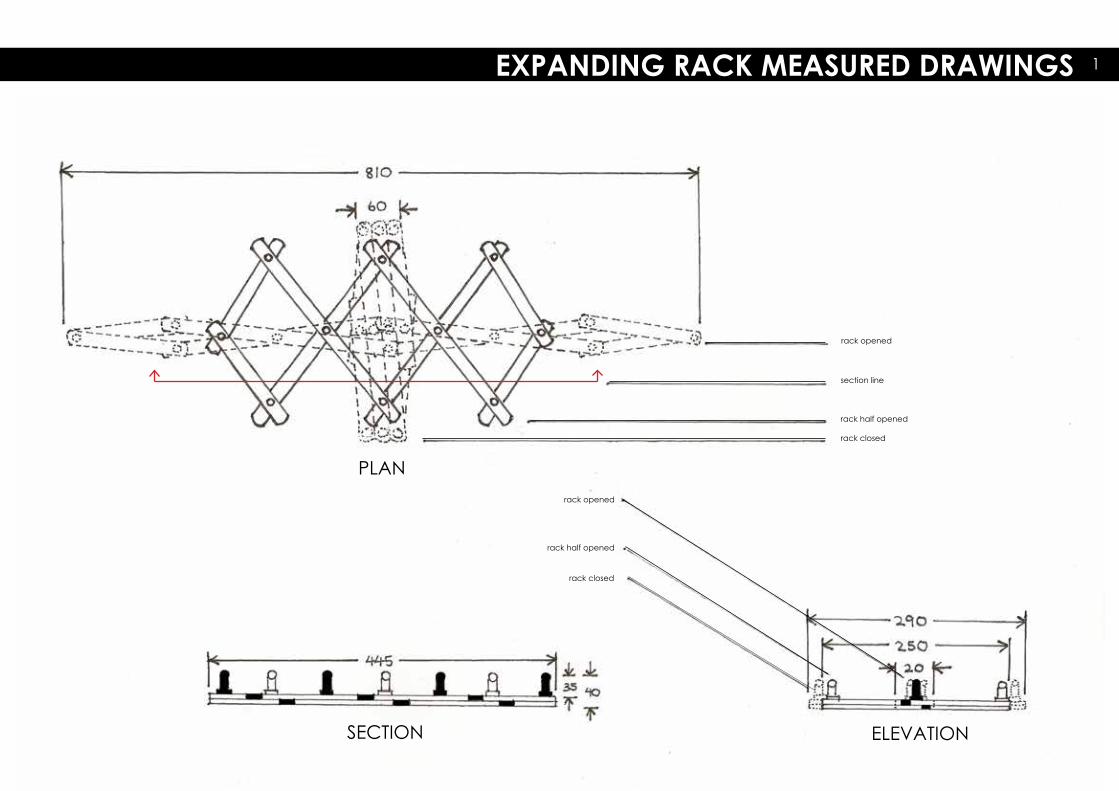
EXPANDING RACK MEASURED DRAWINGS 1

TOP VIEW
FRONT VIEW RIGHT VIEW
AXONOMETRIC VIEW
Heath, Heath and Jensen (2000, p. 7) state that “observation is a necessary part of creation”. Therefore, in order to create a piece inspired by the expanding rack, it has to be firstly observed and measured. Before modelling, I measured each part of the rack using a ruler and observed which planks overlap. In terms of producing
measured drawings onto the page, due to the rack’s symmetrical and reoccuring pattern, once I drew one section of the rack, it was merely amatter of reproducing the pattern. Projecting the object onto Rhino was another important step as representing its structure as a computer model assists in facilitating design and
analysis of its geometric properties (Cheng 2008). These measuring exercises allowed me tothoroughly interrogate the way in which theexpanding rack moves and the mechanismsbehind its expanding capabilities.
EXPANDING RACK RHINO MODEL2

SKETCH OF RACK MOVEMENT VIDEO CAPTURES OF RACK MOVEMENT
There is no one way to measure an object (Heath, Heath & Jensen 2000). Therefore, discovering
new methods in which to represent the object was both a creative and analytical exercise. One component that was of particular interest was the
rack’s ability to expand. Therefore, I wanted to illustrate the full range of movement. The sketch of
the way the rack moves was one such example. By overlapping the various components, it can
clearly outline the reoccuring and logical pattern in which the expanding rack unfolds. In
displaying its movement, a spectacular ability can be “measured” onto paper. Another method of “measuring” the expanding rack was producing
screen captures from filming the expansion of the rack. Heath, Heath and Jensen (2000) argue that photography can support the essential “feeling”
behind the object in focus. In my case,photography of the rack captures the geometric
transition of the rack from a vertically structured object to a singular horixontal structure.
MOVEMENT OF EXPANDING RACK 3

This developmental model was inspired by the folding andexpanding abilities of the expanding rack. Specifically, I wasinfluenced by the way the entire object is able to move by simply moving one of the arms.
Not only does this developmental model move by itself in a similar fashion to the expanding rack, it also creates similarpatterns along the edges of the prismatic shape thus emulating the expanding and folding abilities,
By constructing this developmental model, I really interrogated the way the rack is constructed. For example, I discovered that each arm of the rack acts like a pivot with multiple pivots acting along the same wire. Through this connectivity, the object is able to move in a uniform manner. What is most interesting is that this property does not change even if I extend this concept into a three dimensional volume.
MOVEMENT OF DEVELOPMENTAL MODEL
DEVELOPMENTAL MODEL4
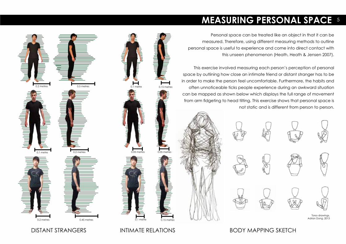
DISTANT STRANGERS
0.5 metres0.2 metres
0.2 metres0.1 metre
0.45 metres0.2 metres
0.15 metres0.1 metre
0.05 metres 0.05 metres
0.15 metres0.1 metre
INTIMATE RELATIONS BODY MAPPING SKETCH
Personal space can be treated like an object in that it can bemeasured. Therefore, using different measuring methods to outline
personal space is useful to experience and come into direct contact with this unseen phenomenon (Heath, Heath & Jensen 2007).
This exercise involved measuring each person’s perception of personal
space by outlining how close an intimate friend or distant stranger has to be in order to make the person feel uncomfortable. Furthermore, the habits and
often unnoticeable ticks people experience during an awkward situation can be mapped as shown below which displays the full range of movement from arm fidgeting to head tilting. This exercise shows that personal space is
not static and is different from person to person.
MEASURING PERSONAL SPACE 5
Torso drawings, Adrian Dong, 2013
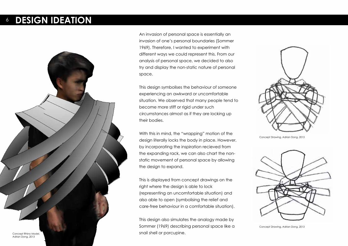
DESIGN IDEATIONAn invasion of personal space is essentially an invasion of one’s personal boundaries (Sommer 1969). Therefore, I wanted to experiment withdifferent ways we could represent this. From our analysis of personal space, we decided to also try and display the non-static nature of personal space.
This design symbolises the behaviour of someone experiencing an awkward or uncomfortablesituation. We observed that many people tend to become more stiff or rigid under suchcircumstances almost as if they are locking up their bodies.
With this in mind, the “wrapping” motion of the design literally locks the body in place. However, by incorporating the inspiration recieved from the expanding rack, we can also chart the non-static movement of personal space by allowing the design to expand.
This is displayed from concept drawings on the right where the design is able to lock(representing an uncomfortable situation) and also able to open (symbolising the relief and care-free behaviour in a comfortable situation).
This design also simulates the analogy made by Sommer (1969) describing personal space like a snail shell or porcupine.
6
Concept Rhino Model, Adrian Dong, 2013
Concept Drawing, Adrian Dong, 2013
Concept Drawing, Adrian Dong, 2013

This design is heavily influenced by theexpanding rack. In fact, as displayed in both
the Rhino model and concept drawings, it utilises similar expanding methods. This design
also considers the non-static nature ofpersonal space but focusing more on one’s
own perception of this phenomenon.
Therefore, this design enables the wearer to have full control on the piece’s opening and
closing mechanisms. Through this, itillustrates that personal boundaries are
different for each person depending on one’s own attitude (Sommer 1969).
Furthermore, this design conveys different emotions. In its closed state, it can represent
a feeling of rigidity as it “locks’ around the neck limiting ones movement. However, when
it is released and the design opens up, it can evoke either a sense of relief or evenaggression similar to the fight or flight
behaviour outlined by Sommer (1969).
This concept was chosen to be refined as it possessed potential in multiple areas including the expanding and folding capabilities similar
to the expanding rack, its symbolism of person-al space and its non-static nature as well as it
acting as a second skin on the wearer’s body.
7

MODULETWODESIGN

In order to refine ideas, we had to produce a prototype and discover what needed to be changed, removed or added.
It was decided that the most importantaspect required to be prototyped first was one of the arms that expanded from the neck brace.
One change made immediately was that the expanding connections would be made of string rather than another solid arm for two reasons: 1. The connections had to expand and contract on their own and 2. Adding a solid connection meant adding another layer within the arm which would make the hinge at the top too thick.
The first prototype was made by 1.00mm cardboard using the card cutter. However, the card was not thick or durable enough to withstand both the strength of the string when pulled, and gravity. The secondprototype was made of 3.00mm boxboard which was more durable but still lacked the rigid appearance I wanted in its folded state.
PROTOTYPE 8

PROTOTYPEThese prototypes began exploring the use of
3.00mm perspex as the material. Variousconnections were tested which simulated the connections between the arms and the neck
brace.
However, the weight of the material was too heavy for the design and even snapped some
of the connections.
Furthermore, using thread to join the arms for the expanding motion was too weak and easily
tangled.
With this added complexity, it was decided that the design was becoming too difficult to
produce. The question here is whether the design is developable. Pottmann et al. (2007) states that a developable surface is one that
can be mapped on a plane isometrically.However, because this design constitutes of more than one structure or surface it delves
deeper than this definition. Each component can be mapped onto Rhino. The difficulty lies in
pieceing each part together.
Therefore, we returned to the drawing board and re-interrogated the expanding rack.
9

Arm Movement Sketch, Adrian Dong, 2013
Rhino Model, Stefan Bjelosevic, 2013
Due to the overly complex nature of the design, it was decided that the focus should return to the expanding rack.
To decrease the weight, all but two arms wereremoved. Furthermore, rather than each armexpanding using the expanding rack mechanisms, each arm simulates an expanding rack itself and unfolds on its own with the control of the wearer.
The expanding and contracting nature of the designreflects the basic idea of the non-static nature ofpersonal space.
Range of Movement Sketch, Adrian Dong, 2013
skin in that it mimmicks the wearer’s movement which in turn is aphysical reflection of the individual’s personal space and how it changes.
DESIGN DEVELOPMENT 10
Concept Sketch, Adrian Dong, 2013
Furthermore, with this design, there is greater movement along the neck brace as itallows the wearer to lift the arms in addition to lowering them.
In essence, it becomes more like a second

Rhino Model, Stefan Bjelosevic, 2013
Hinge System, Adrian Dong, 2013
attention is the way an everyday object can be compressed into such a small volume and then expanded into a larger form automatically.
Although the design effect of Heatherwick’s Rolling Bridge is too complex to recreate, the idea of using movement as part of the design effect can be utilised in this design through the expanding capabilities of the expanding
rack.
Furthermore, with multiple expanding racks layered on top of another, it increases the design’s aesthetic appeal. Therefore, it truly creates a sense
of a second skin while still exploring the idea of personal space and how it is always changing.
This process is similar to the idea of abstraction where one workssystematically to create a solution that solves every critera and suits each
component (Scheurer & Stehling 2011).
Arm Sketch, Adrian Dong, 2013
The design was then refined further as we wanted to make it less like two expanding racks and more like a design which uses the expanding rack for visual effect. We returned to the brief and was inspired to make the design
more of a three dimensional volume encapsulating the wearer. This was achieved by adding another layer to each arm.
Therefore, in order to fulfil the brief and create a volume, extra layers wereadded which simulated the
developmental model made earlier.
Thomas Heatherwick’s Rolling Bridge utilises movement as a visual effect.
What captures the audience’s
DESIGN DEVELOPMENT11
Concept Sketch, Adrian Dong, 2013

This design was created for acontemporary art institution in the United States. It encompasses the ideas of being non-static and continuously evolving in a subtle way. This provides
insight to the idea of the perception of movement.
This installation was constructed using two-dimensional templates with flaps that overlap one another. This in turn forms a three dimensional shape. This is similar to our design where two-dimensional layers have been pieced together to form a volume that aims to convey the idea of a non-static entity.
The rippling appearance of the piece has influenced the way our design is percieved by the audience. Our visual effect depends on lighting refracting off the plastic of our second skin which would create patterns, silhouettes and a shimmering effect.
This is a pavilion that was created as a gathering space in Hong Kong. Thepavilion utilises asymmetrical andabstract forms to create a spatial effect that aims to draw in users.
It creates an illusion of movementespecially with varying sizes of the holes. This effect of the illusion ofmovement can be utilised to simulate the transforming capabilities of the expandable rack. The openings in the structure form an interesting pattern with shadows on the ground thatmirror the pavilion itself when sunlight hits the structure. This combination of light and “movement” can be applied to our design as the lighting effects reinforce the idea of personal space’s non-static nature.
The pavilion uses semi-transparentmaterials to allow light to both pass through and reflect which creates the various patterns on the floor. In turn, a transparent material can be usedto produce the second skin to create the spatial and visual effects.
SHELLSTARPAVILIONMATSYS
Shellstar Pavilion, MATSYS, 2012All photos: Lo, D 2012, Shellstar Pavilion, viewed 3 September 2013, <http://matsysdesign.com/2013/02/27/shellstar-pavilion/>
PRECEDENT STUDIES 12
Shellstar Pavilion, MATSYS, 2012
REEFLISA IWAMOTO & CRAIG SCOTT
Reef, Lisa Iwamoto & Craig Scott, 2007All photos: Iwamoto, L & Scott, C 2012, Reef, viewed 3 Sep-tember 2013, <http://www.moma.org/interactives/exhibitions/yap/2007_iwamotoscott#>
Reef, Lisa Iwamoto & Craig Scott, 2007 Reef, Lisa Iwamoto & Craig Scott, 2007Shellstar Pavilion, MATSYS, 2012

PROTOTYPEThis prototype aims to recreate one of the arms of the design.
It uses transparent 3.00mm perspex which is the material that is planned to be used for the final design. As influenced by The ShellstarPavilion by MATSYS, the plastic allows light to pass through or refract along the edges.
To simulate the expanding abilities of theexpanding rack, a suitable hinge system had to be used. The connections are a combination of nuts, bolts and rubber bands that are then further glued to hold them in place. Thisallows for fluid movement.
Various hole sizes for the nuts were tested prior to the construction of the prototype.
As displayed in the photographs, the arm acts as a second arm or skin of the user. It can move with the wearer and encompasses a large range of movement.
Creating this prototype moves us away from the question of whether or not the design is developable once printed from thecomputer (as questioned by Pottmann et al. (2007)), but rather what kind of pieces are required to be printed from Rhino to create the movable three dimensional volume.
13

MAMANLOUISE BOUGEOIS
These sculptures created by Louise Bougeois immitate the appearance of a spider. Constructed over 10 metres high, there are various versions placed around the world.
The interesting point to note from these structures are the varying sized legs of each portion of the spider leg. These legs can be thought of in the same rationale as the arms of our second skin in that they are all protruding from a central source. Furthermore, within one arm, there are different widths and lengths. This idea can be transported back to our design by altering various measurements of the arms which also illustrate the changing nature of personal space.
By doing so, the second skin structure can become more visually striking similar to the way Thomas Heatherwick captures the user’s attention in his projects such as the Rolling Bridge.
Maman, Louise Bougeois, 1999Photo: Pignel, C 2011, Maman, viewed 3 September 2013, <http://www.clisthene.org/le-musee-guggenheim-de-bilbao/bourgeois_maman4_2001/>
Maman, Louise Bougeois, 1999Photo: New America 2011, Maman, viewed 3 September 2013, <http://an-ewamerican.blogspot.com.au/2011_04_22_archive.html>
Maman, Louise Bougeois, 1999Photo: Villa, C 2011, Maman, viewed 3 September 2013, <http://designmeow.files.wordpress.com/2012/04/maman-louise-bourgeois-photo-catalina-villa-4.jpg>
PRECEDENT STUDY 14
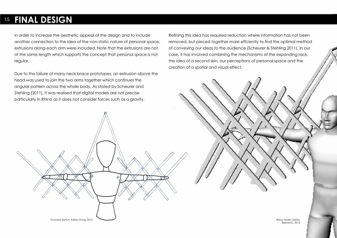
In order to increase the aesthetic appeal of the design and to include another connection to the idea of the non-static nature of personal space, extrusions along each arm were included. Note that the extrusions are not of the same length which supports the concept that personal space is not regular.
Due to the failure of many neck brace prototypes, an extrusion above the head was used to join the two arms together which continues theangular pattern across the whole body. As stated by Scheurer andStehling (2011), it was realised that digital models are not preciseparticularly in Rhino as it does not consider forces such as a gravity.
FINAL DESIGN15
Concept Sketch, Adrian Dong, 2013 Rhino Model, Stefan Bjelosevic, 2013
Refining this idea has required reduction where information has not been removed, but pieced together more effciently to find the optimal method of conveying our ideas to the audience (Scheurer & Stehling 2011). In our case, it has involved combining the mechanisms of the expanding rack, the idea of a second skin, our perceptions of personal space and the creation of a spatial and visual effect.

100
160
170250
330
3
500
12096
140 10
3
FINAL DESIGN MEASURED DRAWINGSCALE 1:5
1985
78816
Measured Drawings, Adrian Dong, 2013
PLAN
SECTION
ELEVATION

Assembly Drawing, Stefan Bjelosevic, 2013
Large bolts are placed on the upper two rows of holes, and providestructural support as well as support for the wearer. One end is secured with
bolts whilst the other is secured with an elastic band. The elastic band is then hardened with super glue. This allows the entire superstructure to maintain
some flexibility whilst still remaining sturdy.
Range of Movement Sketch, Adrian Dong, 2013
SECOND SKIN DESIGN DRAWINGS17
Scheurer and Stehling (2011) state that ideas are often mapped on a three dimensional scale before they are flattened to a two dimensional plane in order for the design to be printed and constructed. However, in the case of our design I think it has been the opposite.
Because of the complexity behind the mechanisms that allow the design to move, the second skin began on a two dimensional plane. Once the basic structure had been achieved, it was then altered to a volume. By approaching the project this way, it made preparing the design forfabrication more straight forward as it had already been considered as to how the design would be put together.
Smaller bolts secure the lower row of holes.They are designed to provide strength, whilst still allowing the wearer some
movement. They are attached on both sides of the arm.
This extended arm acts as a link to the other arm, but also provides support and stability.
Entire design is constructed from sturdy, transparent perspex plastic.

MODULETHREEFABRICATION

FABRICATION OF 2ND SKIN
Iwamoto (2009) states that with the rise of digital technology, there has been a greater
number of designers experimenting with different methods of fabrication. Having access
to the Fablab gave us the opportunity to use machinery that we never had access to
before and in line with Iwamato’s (2009) belief, such equipment is no longer reserved for
professional designers. Furthermore, with design heavily assisted by computer aided design
(CAD) and computer aided manufacturing (CAM), it has enabled greater detail and
precision in the fabrication process (Kolarevic 2003).
A greater variety of technology has also become more readily available. This includes CNC cutting, additive and subtractive fabrication and advanced assembly (eg. robotics)
(Kolarevic 2003). Kolarevic (2003) states that these techniques allow the designer to be more involved with the fabrication process due to the computer information being directly
processed for production. For this project, two sheets of transparent 3.00mm prespex was produced from laser cutting. It consisted of an array of plastic beams of various lengths as
displayed above. Nuts, bolts and rubber bands were also used to lock the joints in place.
A challenge was assemblying the design due to its size and weight. The succesful method involved laying out the first layer and then slowly building the second layer on top using the longer bolts. This process really simulates the “do-it-yourself attitude” described by Iwamoto
(2009, p. 4) as I was forced to think of different methods to piece the design together.
1.
2.
3.
18

Figure 4 illustrates one completed arm of the second skin. It folds very neatly similarly to the expanding rack even with the various extrusions.
We decided that to achieve the lighting effects, light sources had to be placed directly onto the second skin. Therefore, single LEDs were chosen to be used in order to produce the intended lighting effect in a subtle manner.
The lights were tested in a small dark room constructed of three sheets of cardboard (as displayed below). As can be seen, even small LEDs are powerful enough to produce the refractions within the plastic.
Masking tape was used to temporarily fix the LEDs onto the perspex while the wires were soldered together to the battery pack to form a circuit. Again, this sort of fabrication techniques are experimental which is aprocess that is becoming more popular among new designers in today’s digital age (Iwamoto 2009).
4.
5.
6.
19

Unfortunately, the single LEDs were too flimsy and difficult to work with as there seemed to be no method to cleanly fix the lights onto the design. Super glue was
to be used to attach the LEDs but through previous experimentation, it would leave a dirty smudge onto the transparent plastic.
The next option was to use LED chains which included adhesives on the back to easily fix the lights onto the design. A pattern was mapped onto the design.
Applying LEDs gave us the opportunity to combine multiple fabricationprocesses together to form almost a hybrid fabrication technique. This way of
innovative thinking is what is driving the digital revolution in today’s society Iwamoto 2009).
However, after discussions with both team members and tutors, it was decided that LED chains would cause the design to be less appealing visually and that the transparent nature of the perspex would be enough to create the lighting effects
from light sources set at a distance. Therefore, the final presentation will involve an external light source shining directly onto the second skin.
Thus, through this further experimentation, LED lights were removed from the design.
7.
8.
9.
20

10. 11. 12.
Due to the weight of the design, the second skin did not rest on the shoulders steadily orcomfortably. It needed an extra source ofsupport. Therefore, it was decided that elastic had to be sown onto four bolts to hold thesecond skin together.
White elastic was chosen so that it would not be easily seen by the audience. The length was measured and then cut from a roll of regular elastic.
White thread was then used to sew theelastic around the bolt. A fine needle was used to thread the string through the elastic.
Once the sewing was completed, any excess material both elastic and thread were trimmed to leave the design clean and well-crafted.
The elastic was strong enough to support the entire structure on the wearer’s shoulder.
This sort of alteration of the design supports the idea that design never ends and continues right up to the very end. However, the key is to not make designs too complex. Although Iwamoto (2009) talks about excessive complexity in relation to computer modelling, the same can be said for the fabrication process and to keep changes and additions to an essential minimum.
21

FINAL PRODUCT22
The final design in its closed phase as
well as various screen captures of how
the second skin is worn. It also
showcases its expansion ability.

VISUAL AND SPATIAL EFFECTS 23
Under different conditions, the second skin can produce a variety of visual effects. What remains constant though is the spatial effect. As can be seen in the photos taken during the 30 second choreography performance, through theassistance of two other people, the design can be drawn to its most extended form. This spatial effect illustrates the changing state of mind of personal space as it is invaded and vice versa. Another interesting aspect that was discovered was the design’s ability to extend not only sideways, but also in a forwards direction at a variety of angles. Not only does this increase the volumetricproperties of the design, it reinforces the idea of a second skin completely acting as a secondary layer to the body regardless of which direction the wearer moves.
In terms of visual effects, the reflections andrefractions produced along the plastic material is best seen on video as it captures the dynamicnature of the effect. However, even photos can give a decent representation of the shimmering effect produced by the design. As can be seen in the photos, certain portions of the second skinreflect an intense light. When the design is moved by the wearer, the light travels across the design as if illuminating an invisible coating around the wearer’s body. This effect symbolises two things: Firstly, the non-static behaviour of personal space and secondly, the conceptual nature of personal space being an unseen, psychologicalphenomenon that influences the physical lives of every human being. Thus, the design exists on the borderline between invisible and visible.
If worn in a darker room with a single light source,interesting silhouettes and patterns are produced. The black and white photos displayed provide arepresentation of some of the interesting effects the design can produce in a darker setting. Unlike the visual effects in a brighter room, the effects are projected around the wearer (eg. floors and walls) rather than on the design itself.

MODULEFOURREFLECTION
REFLECTION 24
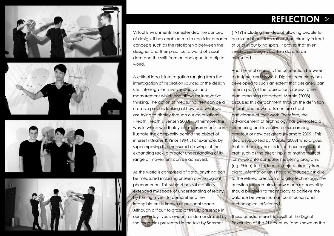
Virtual Environments has extended the concept of design. It has enabled me to consider broader concepts such as the relationship between the designer and their practice, a world of visual data and the shift from an analogue to a digital world.
A critical idea is interrogation ranging from the interrogation of inspiration sources or the design site. Interrogation involves analysis andmeasurement which also allows for innovative thinking. The action of measuring itself can be a creative process looking at how and what we are trying to display through our calculations (Heath, Heath & Jensen 2000). Furthermore, the way in which we display our measurements can illustrate the complexity behind the object of interest (Miralles & Pinos 1994). For example, by superimposing the measured drawings of the expanding rack, a greater understanding of its range of movement can be achieved.
As the world is comprised of data, anything can be measured including unseen psychological phenomenon. This subject has substantiallyextended my scope of understanding of reality by forcing myself to comprehend theintangible entity known as personal space.Although difficult to grasp at first, its presence in our everyday lives is evident as demonstrated by the examples presented in the text by Sommer
(1969) including the idea of allowing people to be closer at our sides rather than directly in front of us or in our blind spots. It proves that eveninvisible paradigms contain data to bemeasured.
Another vital aspect is the connection between a designer and his work. Digital technology has developed to such an extent that designers can remain part of the fabrication process rather than remaining detached. Marble (2008)discusses this detachment through the definition of craft and how craftsmen are directparticipants of their work. Therefore, theadvancement of technology has generated a pioneering and inventive culture amongamateur or new designers (Iwamoto 2009). This idea is supported by Marble (2008) who argues that technology has redefined our concept of craft such as the direct input of mathematical formulae onto computer modelling programs (eg. Rhino) to produce an object directly from digital information. This has also reduced risk due to the refined precision of digital technology. The question that remains is how much responsibility should be given to technology to achieve the balance between human contribution andtechnological efficiency?
These questions are the result of the DigitalRevolution of the 21st century (also known as the

REFLECTION25
Third Industrial Revolution). One aspect of this revolution has been the technological advancement offabrication techniques such as CNC cutting,subtractive and additive fabrication, and advanced assembly (Kolarevic 2003).
However, the other and perhaps more importantaspect of the revolution was the creation of a single network where designers are able to freelycommunicate and generate ideas collaboratively (Rifkin 2011). Rifkin (2011) provides the example of the monumental collection of data on an onlineencyclopaedia. What has not changed though is the continual transference of energy which has remained a part of design throughout history.
Therefore, Virtual Environments has delved beyonddesign and has provided an understanding of the energy that exists behind the design and fabrication processes. By viewing the world as a data matrix, the environment can be manipulated to achieveinnovation through design.
REFERENCES
Heath, A., Heath, D. & Jensen, A. (2000) 300 years of industrial design: function, form, technique, 1700-2000, Watson-Guptill, New York, Selected Extracts
Heatherwick, T. (March 2011) Thomas Heatherwick: Building the Seed Cathedral [Video file] retrieved from http://www.ted.com/talks/thomas_heatherwick.html
Iwamoto, L. (2009) Digital fabrications: architectural and material techniques, Princeton Architectural Press, New York, Selected Extracts
Kolarevic, B. (2003) “Digital Production” in Architecture in the Digital Age - Design and Manufacturing, Spon Press, London, pp. 30-54
Marble, S. (2008) ‘Imagining Risk’ in P. Bernstein, P. Deamer (eds), Building the Future: Recasting Labor in Architecture, Princeton Architectural Press, New York, pp. 38-42 Miralles, E. & Pinos, C. (1994) “How to lay out a croissant” El Croquis, 49/50, pp. 240-241
Pottmann, A., Asperl, H., Hofer, M. & Kilian, A. (eds) (2007) “Surfaces that can be built from paper” in Architectural Geometry, Bentley Institute Press, pp. 534-561
Rifkin, J. (2011) “Distributed Capitalism’ in The Third Industrial Revolution, Palgrave Macmillan, New York, pp. 107-126
Scheurer, F. & Stehling, H. (2011) “Lost in Parameter Space?” AD: Architectural Design, vol 81 pp. 70-79
Sommer, R. (1969) ‘Spatial invasion’ in Sommer, R., Personal space: the behavioral basis of design, Prentice-Hall, Englewood Cliffs, N. J., pp. 26-38