2012 w„rtsil„ technical journal - crasman
TRANSCRIPT

issue no.
012012Tw
enty
four
7.
WÄRTSILÄ TECHNICAL JOURNAL
[ WWW.WARTSILA.COM ]
Flexibility in dispatching Modelling power systems
15
21
ENERGY
MARINE
34
Smaller scale LNG deliveriesLogistics model can open new markets
Composite technologyWärtsilä solutions for seals and bearings
LNG conversions A viable option for environmental compliance
55
page04
COVER STORY
SMART POWER
GENERATION FOR
the oil and gas industry

DEAR READER
issue no. 01.2012 in detail
E-mail and feedback: [email protected]
2 in detail
Flexibility in power generation . . . . . . . . . . . . . . . . . . . . .4
GD power plant conversions . . . . . . . . . . . . . . . . . . . . . . .9
Forecasting power demand . . . . . . . . . . . . . . . . . . . . . . 15
Facilitating smaller-scale LNG availability . . . . . . . . 21
System support enhances use of renewables . . . . . 26
Ancillary services secure power supply quality . . . 31
New composite seal and bearing technology . . . . . 34
LLC offers additional levels of redundancy . . . . . . . 40
Blending on Board improves lubrication . . . . . . . . . . 47
LNG conversion for marine installations . . . . . . . . . . 55
Wärtsilä 32 has greater power output . . . . . . . . . . . . 61
Publisher: Wärtsilä Corporation, John Stenbergin ranta 2,
P.O. Box 196, FIN-00531 Helsinki, Finland | Editor-in-Chief: Marit Holmlund-Sund | Managing Editor and Editorial Office:
Tarja Vuorela | English editing: Tom Crockford, Crockford
Communications | Editorial team: Kärt Aavik, Stephane Debiastre,
Niklas Haga, Marit Holmlund-Sund, Tom Kreutzman, Dan Pettersson,
Marialuisa Viani, Virva Äimälä | Layout and production:
Otavamedia Ltd., Kynämies, Helsinki, Finland | Printed: May 2012
by PunaMusta, Joensuu, Finland ISSN 1797-0032 | Copyright ©
2012 Wärtsilä Corporation | Paper: cover Lumiart Silk 250 g/m²,
inside pages Berga Classic 115 g/m²
ENERGY
MARINE
Contents
The Wärtsilä-powered Antelope Station facility is providing grid stabilisation services in West Texas, one of the USA's premier wind farm locations (more on page 26).
THIS ISSUE OF IN DETAIL is also available on iPad as a Wärtsilä iPublication app from Apple's Appstore, as well as in a browsable web version at http://indetailmagazine.com/.
WÄRTSILÄ CONTINUES to strive to provide, both for land and
sea based applications, power and propulsion solutions that
are reliable, sustainable and affordable. For these are the
shared demands of power plant and ship owners throughout
the world, and a few of Wärtsilä's innovations to meet the
current and future needs of its customers can be seen in this
issue of In Detail.
SMART POWER GENERATION is an outstanding example of
this far-sighted vision in not only responding to the present
situation, but in anticipating the likely requirements of the
energy sector in the years ahead. As utilities everywhere
continue to add renewable power sources, such as wind and
solar, to their systems, they seek also ways of adjusting their
generating capacity to the inherent variability in supply
that these new sources create. Traditional, conventional
systems are not designed for responding to such rapid
variations, and Wärtsilä is a pioneer in providing an
economically sound and technically feasible alternative.
SIMILARLY, WÄRTSILÄ'S LEADING ROLE in developing
multi-fuel engine technology is paying dividends in reducing
operating costs and helping the environment. One clear
example is illustrated in the use of oilfield associated gas to
generate power instead of being flared into the atmosphere.
IN THE SHIPPING AND OFFSHORE MARKETS too, Wärtsilä's
advances in engine technology are enabling the emergence of
liquefied natural gas (LNG) as a viable marine fuel. Despite its
obvious advantages in cost and environmental sustainability,
LNG has for years been looked upon as being impractical
for use in fuelling marine engines. Wärtsilä has shown
the world that this is not the case at all. On the contrary,
thanks to the company’s innovative thinking and dedicated
development work, LNG may well become the marine fuel
of the future. Conversions to gas powered propulsion are,
therefore, likely to increase rapidly as we look ahead.
THESE LARGE-SCALE DEVELOPMENTS, and the many
smaller-scale innovations that are presented in this issue of
InDetail magazine, not only provide Wärtsilä with business
opportunities, they are also reason for every employee
across the globe to be justifiably proud. Above all, they offer
our customers solutions that are
absolutely in line with the need
to meet tightening cost budgets,
and to comply with increasingly
stringent environmental
legislation.
I wish you enjoyable reading,
Frank Donnelly President, Wärtsilä North America Contributing editor to this issue of In Detail
iPad
Web

WÄRTSILÄ TECHNICAL JOURNAL | WWW.WARTSILA.COM
in detail 3
WÄRTSILÄ LOW LOSS CONCEPTNew Wärtsilä platform supply vessel design with LLC achieves the highest possible
Environmental Regularity Number without increasing installed engine power. PAGE 40
Blending on Board concept aids lubrication
After extensive testing, Blending on Board to be installed on a Maersk Line container vessel.
Upgraded Wärtsilä 32 engine
The Wärtsilä VS 465 design vessel being built for Atlantic Offshore will feature the higher-output Wärtsilä 32.
Reduced gas flaring after GD conversion
Successful co-operation with PETROAMAZONAS enables electricity to be produced from associated gas at Eden Yuturi.
MORE ON PAGE 47RE
FE
RE
NC
ES
MORE ON PAGE 65MORE ON PAGE 11

4 in detail
[ ENERGY / IN DETAIL ]
[ EN
ER
GY
/ I
N D
ET
AIL
]
Fig. 1 – A pumping station on the Baku-Tbilisi-Ceyhan pipeline in Turkey. The pipeline, for which Wärtsilä has supplied engines, crosses several mountain ranges.
The oil and gas business is a multi-billion
dollar industry with a huge need for
prime movers – whether in the form of
combustion (reciprocating) engines or
combustion turbines (rotating machines) to
deliver electrical power or mechanical drive.
As oil and gas become more difficult
to recover and operators attempt to
extract more from existing wells, the
demand for investment in power
generation will continue to increase.
Smart Power Generation for the oil and gas industryAUTHOR: Junior Isles, Man in Black Media
The oil and gas industry has a tremendous need for prime movers that can provide electrical power or mechanical drive. With their high efficiency and fuel flexibility, combustion engines offer the most competitive solution.
The total investment in the upstream
segment is currently in the region of EUR
300 - 350 billion a year, a figure that is
expected to grow in the coming years.
The choice of whether to use rotating
or reciprocating machines is one that
operators need to consider carefully,
especially in the face of growing
environmental awareness and the need
for greater energy conservation.
Increasing energy demand continues to

WÄRTSILÄ TECHNICAL JOURNAL 01.2012
5in detail
drive oil and gas exploration in regions such
as the Middle East, Russia, the Caspian and
Latin America. Underground gas storage
projects, and the development of gas
transport and distribution in Europe and
the U.S., are also increasing demand for
investment. For example, the U.K. is
planning to build many new underground
storage facilities to increase its severely
limited storage capability.
Applications
The market for combustion engines in
the oil and gas business can be split into
three segments: power plants, pumping,
and compression.
Power generation: Power plants are often
needed to provide power; the location can
be at an oil or gas field, a refinery, or even
at a compression or pumping plant in cases
when the compressor or pump is driven
by an electrical motor.
Such power plants are much the same as
in the electric utility industry. One of the
key differences, however, is the available fuel
to drive the power plant. Fuels can range
from associated gas to crude oil, have
varying quality and quantity, and often
cannot be burned in turbines.
This is where Wärtsilä’s technology comes
into its own. Wärtsilä has engines that can
run on gas or virtually any liquid fuel. It has
gas engines capable of running on normal
pipeline gas; liquid fuel engines that can run
on crude oil, heavy fuel oil (HFO) or light fuel
oil (LFO); and dual-fuel (gas-diesel) engines
capable of burning gas of varying quality
and liquid fuel at the same time. Gas-diesel
(GD) technology, which is unique to Wärtsilä,
is particularly well suited for oil field power
plants where there can be changes over
time in the quality of the associated gas, as
well as in that of the crude oil produced.
With engines ranging in size from 1 MW
to 23 MW, Wärtsilä can build oil or gas fired
power plants ranging from 1 MW up to 500 MW.
The modular design of Wärtsilä’s solutions
means that plant size can be increased by
adding additional units as the operators’
needs change.
Pumping: The same engines used for
generating electricity can be used for driving
pumps. Wärtsilä has large engines suited for
big pipeline projects. It has supplied engines
to projects such as the BTC Pipeline (see side
story) in Turkey, and the OCP Pipeline
in Ecuador.
An advantage of the Wärtsilä technology
is that its engines can run on the crude oil in
the pipeline without any refining or treatment.
Compression: Gas compression is a big
market for combustion engines. Gas
compression is a business worth several
billion dollars a year globally.
Smaller 0.5 - 2 MW engines are used for
small gas distribution lines, as well as in
the shale gas market, which are typically
very small fields.
Larger engines are used for underground
gas storage projects. Indeed, reciprocating
technology is better suited than centrifugal
technology for the high pressures needed
for underground storage.
Currently, the pipeline compression
sector has a prevalence of turbines driving
centrifugal compressors. The turbines used
for this application are typically 5-10 MW
but can also be bigger.
However, using combustion engines to
drive centrifugal compressors offers huge
savings in fuel. The arrangement would see
a gas engine driving the compressor directly,
or a power plant supplying electricity to
electrically driven compressors. Although
the latter would be a more expensive solution,
it would increase flexibility. Using a gas
engine in place of a gas turbine also provides
much better fuel efficiency. Lifecycle studies
of real cases show that such a solution could
deliver fuel savings of more than
EUR 100 million over a 20-year period.
Better efficiency
The efficiency argument presents a strong
case when comparing combustion engines
with other technologies. When a lifecycle
cost evaluation is made, the fuel cost over
the lifetime of a plant is many times that
of the capital expenditure cost.
Historically, operators of power plants,
and compression or pumping stations,
have paid little attention to fuel efficiency
as the fuel is often provided free of charge
from the owners of the field. With free fuel
meaning low operating costs, the main
impact on profitability is capital investment
i.e. the cost of equipment. Operators have
therefore opted for the cheapest equipment,
which is usually not the most fuel-efficient.
But this is changing. As energy prices
continue to increase, efficiency is becoming
an important part of the evaluation process.
In order to save energy, reduce the
environmental impact and cost, energy
efficiency programmes are now common
in the production of oil and gas.
As a traditional industry, oil and gas
operators have a tendency to use technology
they are familiar with. This often means that
when issuing tenders, only turbine
technology is specified, despite their much
lower efficiency compared to combustion
engines.
Although some larger gas turbines can
demonstrate efficiencies of around 40
percent, the smaller turbines (around 10 MW)
typically used in many applications have
an efficiency of about 30 percent or less,
depending on operating conditions.
Efficiency decreases during part-load
operation, and there is a significant drop-
off in power as the ambient temperature
increases. Gas turbines also lose output
and several percentage points in efficiency
due to wear between overhauls.
By comparison, Wärtsilä’s gas and diesel
combustion engines have shaft efficiencies
of around 45-48 percent. Efficiency above
40 percent is maintained even at loads as

6 in detail
[ ENERGY / IN DETAIL ]
[ EN
ER
GY
/ I
N D
ET
AIL
]
low as 50 percent. Gas engines lose virtually
no efficiency over time, and liquid fuel
engines lose only about one percent between
overhauls of the fuel injection system.
Unlike combustion turbines, combustion
engines do not derate over time but
maintain full output during their lifetime.
Fuel flexibility
The ability to burn almost any liquid or
gas fuel in a Wärtsilä engine can help to
drastically reduce the cost of fuel, even from
a purely logistical standpoint.
The ability to run on a wide range of fuels
is why combustion engines are playing a
major role in the drive to reduce flaring.
Gas flaring is a practice that is coming
increasingly under the spotlight due to
environmental concerns and the need for
energy conservation.
In 2010, Wärtsilä became the first solution
provider to become a member of the Global
Gas Flaring Reduction Partnership (GGFR).
The GGFR was formed by the World Bank
in 2002 to support the efforts of oil producing
countries and companies to increase the use
of associated natural gas, and thus reduce
flaring and venting. It estimates that over
138 billion cubic meters (or 4.9 trillion cubic
feet) of natural gas is being flared and vented
annually.
This is equivalent to 25 percent of the
United States’ gas consumption, 30 percent
of the European Union’s gas consumption,
or 75 percent of Russia’s gas exports. The gas
flared yearly also represents more than
the combined gas consumption of Central
and South America.
At a gas price of about USD 4 per million
Gas engines: Wärtsilä gas engines are
suited to normal pipeline quality gas.
They are spark-ignited (SG) engines
that use the lean-burn Otto cycle.
In this process, the gas is mixed with air
before the inlet valves. During the intake
period, gas is also fed into a small pre-
chamber, where the gas mixture is rich
compared to the gas in the cylinder. At
the end of the compression phase the gas/
air mixture in the pre-chamber is ignited
by a spark plug. The flames from the
nozzle of the pre-chamber ignite the gas/
air mixture in the whole cylinder. After
the working phase, the cylinder is emptied
of exhaust and the process starts again.
Oil-fired engines: Wärtsilä liquid fuel
engines can run on crude, heavy fuel
oil (HFO) or light fuel oil (LFO). In the
diesel process, liquid fuel is injected into
the cylinder at high pressure by camshaft-
operated pumps. The fuel is ignited
instantly due to the high temperature
resulting from the compression.
Combustion takes place under constant
pressure with fuel injected into the cylinder
during combustion. After the working
phase, the exhaust gas valves open and
the cylinder is emptied of exhaust gases.
With the piston in its upper position, the
inlet valves open just before the exhaust
gas valves close, and the cylinder is filled
with air. In Wärtsilä engines the inlet
valves close just before the piston reaches
the bottom dead centre. This method,
Wärtsilä engine technology
Fig. 2 – Wärtsilä's gas-diesel technology offers the opportunity to reduce flaring of associated gases, thereby enabling fuel savings and a reduction in greenhouse gas emissions.
Btu, the value of the gas flared in oil fields
and refineries today is around USD 20
billion a year. This wasted associated gas
could produce 65 GW of electricity a year.
With Wärtsilä’s gas-diesel technology,
associated gas can be used for power
generation or gas re-injection at the oil field.
Its fuel sharing technology allows
the engines to cope with variations in gas
quantity and quality.
Reliability
Another key benefit of using combustion
engines is the high reliability they provide.
Oil and gas are highly valuable
commodities and any failure in, for example,
pump or compression equipment can have
serious financial consequences.
Operators, therefore, always install spare
or backup engines or turbines to ensure
there is no interruption in oil or gas
production.
There is a general perception that a
turbine is more reliable than an engine due
to its fewer moving parts. However, modern
WÄRTSILÄ TECHNICAL JOURNAL 01.2012
7in detail
medium speed engines have been proven to
provide reliability equal to that of turbines.
With the clear benefits of better
reliability, greater fuel flexibility and lower
operating costs, it is time for the oil and
gas industry to change its conservative
mindset and focus on using the more
efficient and environmentally friendly
solutions that combustion engines provide.
called “Miller timing”, reduces the work
of compression and the combustion
temperature, which results in higher
engine efficiency and lower emissions.
Dual-fuel engines: Fuel flexibility and
high efficiency are the main advantages
of the dual-fuel technology. They can
be characterised as “anything in, and
anything out”. They can run on crude
and other liquid fuels as well as gas of
varying quality, and can be used for
power generation, combined heat and
power, pumping or compression.
Wärtsilä dual-fuel engines are unique
because they have two different injection
systems. A micro pilot injection system
injects a very small amount of liquid
fuel when the engine is operating in
gas mode. The micro pilot system is of
the common rail type, which allows
for very small injection amounts.
This makes it possible to meet very
stringent emission regulations, which
would be impossible if a normal injection
system were used. A conventional injection
system is used when the engine is run on
liquid fuel. The engine transfers from gas
to fuel oil operation (LFO, HFO) at any
load instantaneously and automatically.
Because the gas is injected to the
engine at high pressure, the engine
is not sensitive to the methane
number or other gas components.
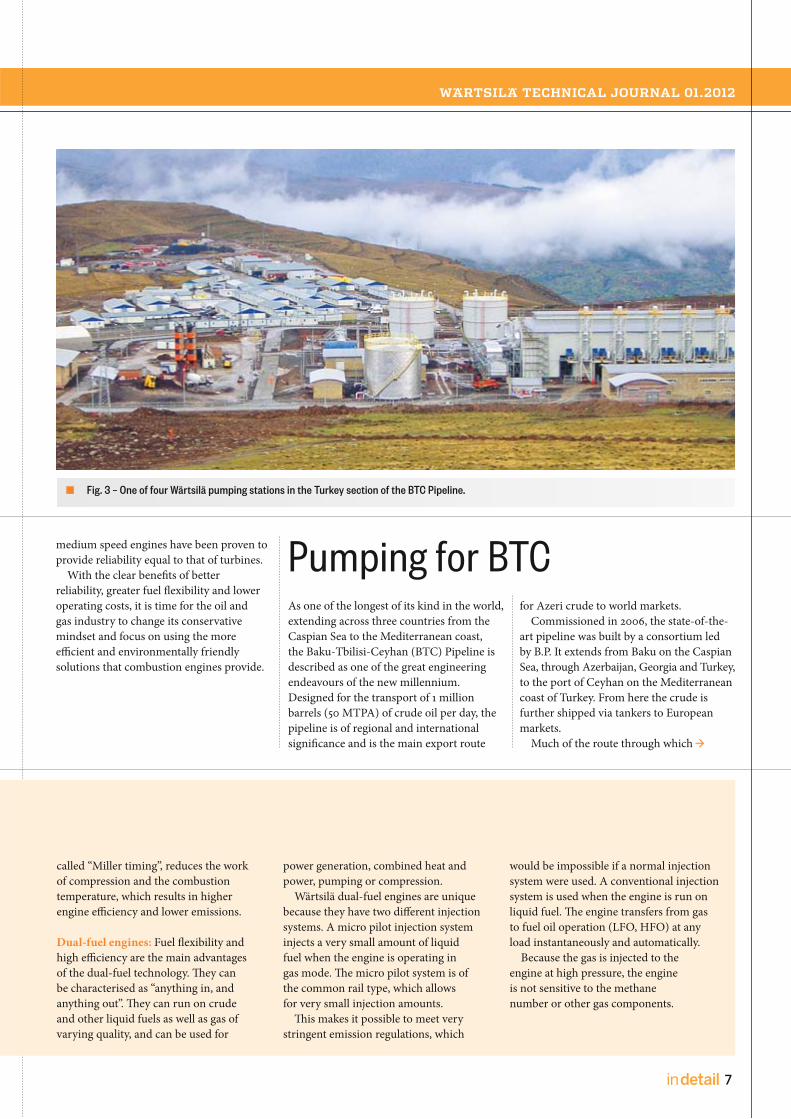
Fig. 3 – One of four Wärtsilä pumping stations in the Turkey section of the BTC Pipeline.
Pumping for BTCAs one of the longest of its kind in the world,
extending across three countries from the
Caspian Sea to the Mediterranean coast,
the Baku-Tbilisi-Ceyhan (BTC) Pipeline is
described as one of the great engineering
endeavours of the new millennium.
Designed for the transport of 1 million
barrels (50 MTPA) of crude oil per day, the
pipeline is of regional and international
significance and is the main export route
for Azeri crude to world markets.
Commissioned in 2006, the state-of-the-
art pipeline was built by a consortium led
by B.P. It extends from Baku on the Caspian
Sea, through Azerbaijan, Georgia and Turkey,
to the port of Ceyhan on the Mediterranean
coast of Turkey. From here the crude is
further shipped via tankers to European
markets.
Much of the route through which

8 in detail
[ ENERGY / IN DETAIL ]
[ EN
ER
GY
/ I
N D
ET
AIL
]
Fig. 4 – BTC pump station with five pump sets driven by Wärtsilä 34SG engines.
the pipeline passes is mountainous. From
the lesser Caucasus Mountains on the border
with Georgia, the pipeline heads west across
the Anatolian Plateau before crossing south
through the Taurus Mountains. At this point
it follows a steep descent to the Cukurova
plain on the north shore of the Gulf of
Iskenderun.
The Anatolian Plateau forms the
principal landform on the route. The terrain
comprises a number of broad plains at
elevations between 1500 m and 2000 m
above sea level, and upland mountains
rising to 3000 m. With a total length of
1769 km, the major portion (1076 km) of
the pipeline’s route is located in Turkey.
Pumping oil across such a vast distance
and high elevations called for the installation
of eight pumping stations – two in
Azerbaijan, two in Georgia and four
in Turkey.
The BP consortium awarded the entire
design and construction of the Turkish
section of the pipeline, including the
pumping stations, to BOTAS, the Turkish
Petroleum Pipeline Corporation.
In 2002, BOTAS awarded a contract to
Wärtsilä for the equipment for the four
stations in Turkey. The scope of the contract
covered the supply of nineteen 18-cylinder
Wärtsilä 34SG engines in V-configuration
with selective catalytic reduction (SCR)
systems, a starting air system, lube
oil systems for the engine, and for the
pump and gear box, cooling radiators,
auxiliary modules for heat exchangers
and filters, air intake ducts, exhaust gas
systems, and pump seal oil systems.
The BTC pump stations in Turkey,
installed along the pipeline from the Georgia
border down to the Ceyhan Marine Terminal,
are designated PT1, PT2, PT3 and PT4 and
are at elevations of 2140 m, 1720 m, 2028 m
and 1595 m, respectively above sea level.
The gas fired reciprocating engines offer
several significant benefits. Compared to
gas turbines, reciprocating engines have
the main advantage of retaining high
efficiency at high altitude. A reciprocating
engine has an efficiency of about 40 percent
compared to less than 30 percent for a gas
turbine driver. Gas turbines experience a
significant loss of power at higher altitudes
and are further handicapped by a steep drop
in efficiency at deviations from the design
point.
Following more than five years of
operation, BTC and Wärtsilä are considering
modernising the engine automation
system with the introduction of a torque
measurement system. This would allow the
engines to automatically adjust according
to the flow of oil in the pipeline.

WÄRTSILÄ TECHNICAL JOURNAL 01.2012
9in detail
Fig. 2 – Gas re-injection combined with power generation.
Fig. 1 – The Wärtsilä solution for re-injecting associated gas into the oil well. This maintains the pressure, enhances oil production, and can even be used as a means of storing gas for later use.
Wärtsilä s gas-diesel (GD) technology was introduced in 1987 with the Wärtsilä 32GD, the first gas engine in the Wärtsilä portfolio. This technology has been used mainly in offshore applications, but has later found applications in the power plant sector.
GD technology makes it possible to run
a power plant on either associated gas or
crude oil, where the gases could contain
heavy hydro-carbons, or heavy fuel oil to
provide the operator with fuel versatility
and security against gas supply disturbances.
The system accommodates daily/frequent
variations in gas quality and quantity.
GD- power plants
In power installations, the economic viability
of gas is becoming ever more apparent.
At the same time, emission issues related to
the use of liquid fuels are becoming more
complex. Not surprisingly, therefore, the
use of gas to generate power is rapidly
increasing, although in order to convert
older LFO /HFO operated installations to
natural gas, there needs to be a reliable
Gas-diesel conversions for power plant applicationsAUTHORS: Jyrki Anturaniemi, Project Proposal Manager, Project Proposals , S olut ion Management
Sergey Cheprasov, Project Manager, S ervices Projects Nor th America
Heikki Huhtala, Project Manager, S ervices Project Centre Finland

10 in detail
[ ENERGY / IN DETAIL ]
[ EN
ER
GY
/ I
N D
ET
AIL
]
supply of gas available. Nevertheless,
the conversion of a HFO plant to natural
gas offers several benefits that make this
upgrading feasible for many customers.
Currently, a conversion project can be
offered using most of the Wärtsilä 32,
Vasa 32 and Vasa 46 engines. Typically,
the two main drivers for fuel change are:
Reduced emissions and fees
Reduction of fuel costs.
The GD conversion concept
Wärtsilä's gas engine portfolio (GD, SG and
DF types) is well known, and if the current
total running hours are, for example, less
than 10,000 hours, a GD conversion is
feasible. In any case, the number of engine
parts that need to be changed is limited.
Diesel engines provide one of the best heat
rates, while GD engines in addition to this
also enable the use of most gas types
available on the market.
There are a number of factors to take into
account when considering a gas conversion.
The most logical place to start is to establish
whether or not the existing engines on site
can be converted, or if they should be
exchanged for new ones. Converting an
existing engine is usually economically more
feasible than installing a new one, especially
since a conversion basically brings the same
benefits as a new engine. For example, the
same warranty is granted as for a brand
new engine. Furthermore, there are also
savings to be made on maintenance costs
since the running hours are reset to zero
(0). However, with smaller installations,
e.g. below 10 MW, it would most likely be
more cost effective to install new engines.
The plant equipment required for
operating on gas can be divided into six
main areas:
Gas delivery
Gas compressor
Fig. 3 – W2W: The Waste To Wire schematic process.
Well
Water
Separator
Crude oil
Gas Pre
-co
od
er
Co
od
er
Tre
atm
en
t
Se
pa
rato
r
Co
mp
ress
ion
Ve
sse
l
Power Generation

WÄRTSILÄ TECHNICAL JOURNAL 01.2012
11in detail
High pressure gas
High gas pressure oil
Control
Electrical feed.
Each gas conversion is installation specific,
and requires a basic engineering evaluation
before a detailed offer and scope can be
given. The scope can encompass a turnkey
delivery that includes the installation and
commissioning of the plant. The plant’s gas
supply and gas line connection to the gas
delivery system is normally the
responsibility of the customer. The most
important benefits of such a conversion are
lower emissions, improved plant efficiency,
and the fact that all the work can be done
on site.
Currently there is an upsurge in demand
for gas conversion installations, based on an
increase in gas supply. In countries without
pipeline gas, liquefied natural gas (LNG)
offers a potential alternative solution.
Gas conversions are yet another example
of Wärtsilä´s ability to help owners and
operators throughout the lifecycle of their
investment, and the company can offer
a broad variety of possibilities to meet
each customer´s specific requirements.
Wärtsilä is also supporting its customers
in gas conversions by providing relevant
training courses on gas operation
Eden Yuturi Conversion Project
In 2008, PETROAMAZONAS EP (PAM), an
Ecuadorian state owned oil company,
initiated a mission named “Optimisation
Generation Electric- OGE” that they also
nominated as a Waste to Wire, or Well to
Wire (W2W) project.
During the crude oil extraction process,
crude oil, water, and associated gas
come to the surface, where they are then
separated at the production facilities (see
Fig. 4 – Associated gas supply characteristics.
Figure 3). Given the unstable condition
of the associated gas (both in terms of
composition and supply) it is usually
vented or flared. The World Bank-led
‘Global Gas Flaring Reduction Partnership’
estimates that globally this amounts to
approximately 150 billion cubic meters of
gas each year, causing some 400 million
tons of carbon dioxide emissions. That is
equivalent to 30 per cent of the European
Union’s total gas consumption. It is
important to point out that associated gas
is quite different to natural gas, in that
its composition and volumes change
significantly over time. If you add to this
the fact that the supply of associated gas
is extremely unstable (see Figure 3), it
becomes clear why in most cases the oil
companies prefer to simply vent or flare it.
In order to reduce gas flaring at the
Eden Yuturi site, PETROAMAZONAS EP and
Wärtsilä entered into a joint development

12 in detail
[ ENERGY / IN DETAIL ]
[ EN
ER
GY
/ I
N D
ET
AIL
]
agreement aimed at developing an integrated
"gas/crude" product, able to cope with the
dynamic condition of associated gas. In
line with the technological developments,
PAM and Wärtsilä jointly developed the
Clean Development Mechanism (CDM)
programme as a means to co-finance the
project. The objectives of the project are to
mitigate the environmental impact through
reducing the exhaust and noise emissions;
to develop and implement a flexible solution
that will adjust to the challenging conditions
of associated gas; and to replace the use of
diesel/crude oil for power generation by
utilizing the associated gas.
Technology
Thanks to Wärtsilä's multi-fuel technology,
associated gas can be converted to electricity
instead of being continuously flared into the
atmosphere. This technology offers a unique
degree of fuel flexibility, permitting the
engines to run on any combination of liquid
fuel and associated gas. This is essential for
oil and gas companies operating in
environments where the associated gas
volumes and composition are constantly
changing. This flexibility in the utilization of
associated gas serves to maximize power
production while, at the same time, reducing
greenhouse gas emissions.
Although the first phase of the project has
been completed, PAM and Wärtsilä are
already looking at taking the "energy
efficiency" concept to a next phase by
developing new state-of-the-art technological
features. The overall goal is to eliminate any
waste, thereby allowing PAM to reduce
the "carbon footprint" per barrel of crude
oil extracted.
The Project Outcome
The conversion of the Eden Yuturi power
plant from crude oil-fuelled to associated
gas-fuelled operation enabled PAM to
utilize associated gas that was being flared.
Four 18-cylinder Wärtsilä Vasa 32 low nox
gas (LNGD) engines in V-configuration
generating 20 - 24 MW power were
converted, and the hand-over to PAM took
place in November 2011. Every 1 million
cubic foot per day of flare gas optimised for
power generating represents approximately
160 barrels of crude oil per day. Thus,
PAM expects to save up to 640 barrels
thanks to the project. As PAM likes to say:
it increased the net crude oil production
by an average of one well without having
gone through the drilling process.
The PETROAMAZONAS EP and Wärtsilä
co-operation succeeded in developing an
"in-house" Ecuadorian Project Team and
Project Implementation Structure capable of
taking a project from an idea to commercial
operations. This has been duly recognized
by the government of Ecuador, which has
now decided that this vehicle should be used
to implement energy efficiency projects
throughout the country's petroleum sector.
Furthermore, technological solutions
were developed and implemented that
focused on mitigating the challenges of
quantity and quality fluctuations in the
delivery of associated gas. At the same
time, PAM’s power supply matrix was
re-engineered so that today more than
60 MW of capacity has been installed to
operate with associated gas. This will be
increased to 70 MW in phase three. The
other critical technical achievement of the
project has been the transformation of
isolated power generation systems towards a
distributed power system, by installing low
environmental impact underground cables.
Wärtsilä's multinational team can reflect
on a successfully implemented solution for
PAM. It has also created an international
benchmark for oil sector energy efficiency
and consequently, a business model that
focuses on long term sustainable prosperity.
Carbon Finance
The gas conversion is expected to save
over 1Mt of CO2 emissions over 10 years
by using previously flared gas for power
generation. In parallel with Wärtsilä's
delivery of the gas conversion project, the
Development and Financial Services group
at Wärtsilä assisted PAM in the successful
registration of the project under the UN’s
Clean Development Mechanism. During the
2 ½-year process Wärtsilä's carbon finance
experts guided the PAM CDM team in the
CDM registration process, and arranged
the sale of Certified Emission Reductions
from the project. The income from the
Certfied Emission Reductions provides
an ancillary income stream for PAM over
at least 10-years and was one of the key
elements in the investment decision.
Aksa Samsun conversion project
Aksa Enerji Uretim A.S, a part of Kazanci
Holding, is one of Wärtsilä’s biggest
customers in Turkey. This energy sector
company operates diesel and gas power
plants, wind farms, hydro-electric plants,
solar energy, biogas and landfills, as well
as distributing and selling electricity.
The company made an agreement with
Wärtsilä in early 2000 for the supply of a
120MW power plant, equipped with seven
18-cylinder Wärtsilä 46 engines, to the
Turkish city of Samsun on the Black Sea.
The Samsun region has industry, but is also
an agricultural area and the local authorities
pay considerable attention to environmental
impacts. The emission levels from the big
factories and power plants were, therefore,
of high concern already at that time and
the Wärtsilä power plant was equipped
with SCR and SOx scrubber systems.
With the tightening of Turkey’s
environmental legislation, the company
was anxious to convert the engines to
use more environmentally friendly fuel.
At the same time, however, it had to be
kept in mind that the rated output from
the engines could not suffer any losses.
Additionally, operating costs needed to be
Fig. 5–6 – Gas Flaring at Eden Yuturi before and after the GD conversion.

WÄRTSILÄ TECHNICAL JOURNAL 01.2012
13in detail
Fig. 7–8 – Aksa Samsun before and after the GD conversion.
reduced to make the plant’s operations more
economical. Since the engines were running
for only 5000 hours each, only minor
modifications to the engines were preferred.
Wärtsilä’s suggestion for the challenge was
a GD concept, which could cope with all
the requirements with improved engine
efficiency, yet still be able to provide not
only back up fuel flexibility with HFO and
LFO, but also natural gas/HFO fuel sharing.
As the undersea natural gas pipeline from
Russia already exists in the city of Samsun,
the set up was clear, and the GD concept
was proposed as a means of continuing the
plant’s operation under the tight emission
laws. The EEQ contract to convert six of the
power plant’s engines to GD operation was
signed in November 2009, and the project
team’s involvement began accordingly. The
seventh engine was relocated to Cyprus
by Aksa Enerji during the execution of the
GD conversion project in order to make
room for the first Wärtsilä 50SG engine.
Safety is the driving force
Safety is imperative when using high pressure
gas as a main fuel. The fuel oil system, gas
detection and automation system, and the
fire fighting system were designed according
to stringent safety regulations. Different
ratings and areas of Ex-zones were
determined, and even the access road to the
power house building had to be changed
due to the compressor house design and
location. Ex-proof components were
considered for all electrical and automation
parts, when located inside the Ex-zone.
A new gas feed arrangement with double
wall piping, a new HFO injection system, a
control oil system for 370 bar pressure, and
a new improved engine control were added
to the engine. Basically, therefore, very minor
modifications to the engine itself were
required.
For external systems, the conceptual
design was made through close co-operation
between Wärtsilä and Aksa Enerji A.S
Uretim. A ‘Safety Concept with a Cause &
Effect’ study was made by Wärtsilä and Aksa
Enerji based on the Wärtsilä GD concept and
local regulations, and this was used as a
design and execution guideline. The safety
concept emphasizes all the necessary aspects
and measures included in the GD power
plant concept to achieve an acceptable
safety level.
An optimal gas feed system based on
the local conditions was calculated and
designed by Wärtsilä experts together with
Aksa Enerji A.S Uretim’s gas department.

14 in detail
[ ENERGY / IN DETAIL ]
[ EN
ER
GY
/ I
N D
ET
AIL
]
The gas itself is good quality Russian
natural gas with high low heat value
(LHV), a low consistence of inert gases,
and high methane number (MN). Two high
pressure gas compressors supply the six
Wärtsilä 46GD engines via an engine wise
gas valve skid, which is also able to share
the load upon request from the Wärtsilä
plant control system. The gas feed piping
inside the power house is double walled
to enable proper ventilation for the safe
evacuation of any possible gas leaks. A
reliable, sufficient, and safe gas feed into
the engine is an important factor, but the
gas blow down and venting cannot be
overlooked. Because of maintenance or
other planning reasons, the gas flow must
be able to be led out (blow down) from the
system back to the gas grid. This must be a
safe and controllable operation. There is a
further need for emergency venting of the
gas flow into the atmosphere, which has
to be well planned so that it is activated in
accordance with the plant controls, etc.
A project specific gas valve skid was
tailored by the project team to achieve the
optimal reliability and performance for
operation with a very low, <2 bar, pressure
drop over the skid. The gas valve skids
were further located inside the gas tight
individual cabinet, which is continuously
ventilated and furnished with gas detection
equipment that issues a gas alarm in case
of any leak or malfunction of the skid.
Testing and commissioning took place
in autumn 2011, engine by engine, by the
Wärtsilä commissioning team assisted by
the Aksa Enerji team. Start up of the GD
engine is carried out using LFO or HFO,
and then ramped up to 25% to 30% on
fuel sharing mode prior to change over
to full gas operation with an HFO fuelled
pilot. After a few days tuning, the 17 MW
was reached with very good heat rate
figures. Furthermore, the key issue, the
exhaust gas emissions, were accepted by
the local authorities, who are continuously
monitoring the plant’s exhaust gas emissions
via engine wise emission sensors installed
on each exhaust gas stack. So, in other
words, the production of electricity can
continue with far lower levels of exhaust
gas emissions, while providing financial
benefits through lower operation costs. An
additional advantage is that HFO no. 4, or
even no. 6, can be used as a pilot fuel to
reduce the operational costs even more.
New automation
No conversion project is without a
challenge or a surprise of some kind. This
is especially true when something new
has to fit into an existing environment.
The engine and plant automation and
monitoring systems were renewed totally, so
old panels, sensors, etc were disconnected
and removed prior to assembly of
the new ones, which were also partly
interconnected to the existing systems. In
addition, considerable quantities of safety
equipment, including detectors, sensors,
limit switches, and so on, were installed
based on the required safety concept. Once
the dismantling and installation work
was finalised, the software needed to be
updated to the final revision, and once
again this was based on the safety concept
and the final setting of the equipment.
Overall, however, through close and
open co-operation with the customer, the
Wärtsilä organizations in Finland and
Turkey, and other stakeholders meant that
no major surprises occurred - even though
the project specific and tailored design
was developed during the project itself.
Fuel flexibility
Wärtsilä products are flexible and easily
adaptable for utilizing gas as a main fuel.
This makes the converting of power
plants to gas operation very interesting,
for example in terms of lower operation
costs, less exhaust gas emissions, fuel
flexibility, and short payback time. This
is especially important now when the
gas grids are expanding and emission
levels are being tightened globally. The
GD concept requires very few engine
modifications, and provides considerable
benefits with real fuel flexibility.
Fig. 9 – Pressure testing of the gas pipeline.

WÄRTSILÄ TECHNICAL JOURNAL 01.2012
15in detail
Fig. 1 – In a wind integration study for the Mid Western United States, the PLEXOS® simulations quantify the ability of Wärtsilä Power Plants to load follow against rapidly changing wind output.
The modelling of power systems AUTHOR: Kimi Arima, Advisor, Advisory S ervices, Marketing and Business Development
How does one quantify the value of flexibility? For this one would have to model an entire power system, insert flexible power generation, and observe the results. Wärtsilä has a tool that can do just this.
Dispatching
Dispatching could be concisely described
as the act of continuously optimising the
operation of the power system from one
minute to the next. In the context of a
developed and complex power system,
the responsibility for dispatching usually
resides with the system operator. To be
able to optimise the power system, the
system operator is continuously engaged
in three activities that define dispatching:
forecasting, planning, and controlling.
Forecasting is the task of finding out the
expected load demand and what generating
assets are available to meet that demand.
For traditional longer-term forecasting,
considerations include seasonal variations
in load demand, macro-level weather
patterns and their effect on demand, as
well as planned outages of large generating
units. Shorter term forecasting involves
daily load variations and, which is of
increasing importance in many systems,
the output of intermittent renewable power
generation. The result of forecasting is a
net load curve, that is, the forecasted load
demand less the forecasted output from
intermittent renewable power generation.
This is the part of demand that needs to be
met with dispatchable power generation,
i.e., generating units that can be started
and stopped as and when needed.

16 in detail
[ ENERGY / IN DETAIL ]
[ EN
ER
GY
/ I
N D
ET
AIL
]
Based on the forecast, the system operator
can plan which generating units will be
used to meet expected net load demand
at each point of the coming day. One
approach is to rank the units in the system
in ascending order of their marginal cost
of generation, known as a merit order.
Renewable sources come first, as they
have no fuel costs. These are followed by
nuclear and coal plants, which typically
have very low marginal operating costs,
notwithstanding the emission costs imposed
on coal plants in some countries. Next come
CCGTs, combustion engines, and OCGT
plants running on gas, while possible oil-
fired units come last, as their fuel costs
are the highest. Having planned which
generating units need to be running and at
which times, the system operator accounts
for start up times and ramp up rates to
see when each generating unit needs to be
started up. In case a generating unit has
to be started up twice during the day, the
minimum uptime and minimum downtime
also have to be taken into consideration.
Finally, contingencies, such as a
malfunction in a big generating unit, or a
forecasting error, also have to be accounted
for. Some generating units are needed to be
at the ready in case of an unexpected shift,
positive or negative, in net load demand.
Reserve requirements are system-specific,
and can be met with a combination of
spinning and non-spinning generating units.
In many countries, the planning phase
takes place on the market. Plant owners bid
their production onto the market, whereby
a merit order is established according to
bid prices. Reserves can also be organised
via separate market mechanisms.
In parallel with forecasting and planning,
continuous controlling is needed to keep
frequency stable throughout the grid, and
maintain stable voltage locally. Routine
control chiefly revolves around the dispatch
plan based on forecasts and the merit
order. If actual demand deviates from
the forecast too much or too quickly, for
whatever reason, reserves will be called
upon to regulate generation as needed.
The goal of dispatching is two-fold. The
first objective is to ensure security of supply.
In the short term, this is achieved mainly
by successful controlling of the system.
In the longer term, forecasting accuracy
needs to be maintained, and reserves
capable of meeting both the scale and speed
of unexpected variations are required.
45
40
35
30
25
20
15
10
5
0
GW
00 01 02 03 04 05 60 07 08 09 10 11 12 13 14 15 16 17 18 19 20 21 22 23Hour
Dispatchable
Wind
Solar
Fig. 2 – Net load curve, actual data in a Spanish power system. Notice the difference between the smooth curves of aggregate demand and the output of dispatchable power generation.

WÄRTSILÄ TECHNICAL JOURNAL 01.2012
17in detail
Fig. 3–4 – The generation curves in the graph to the left are the result of one hour resolution, whereas the actual generation data in the graph to the right shows generation on a 10 minute interval basis. The surge in wind output and subsequent rampdown of CCGT output between 6 and 7 am is almost invisible in the one hour resolution forecast.
50
40
30
20
10
0
Hour
GW
00 01 02 03 04 05 06 07 08 09 10 11 12 13 14 15 16 17 18 19 20 21 22 23
HYDRO-RoR
NUCLEAR
CCGT
WIND
OCGT
COAL
00 01 02 03 04 05 06 07 08 09 10 11 12 13 14 15 16 17 18 19 20 21 22 23
50
40
30
20
10
0
Hour
GW
HYDRO-RoR
NUCLEAR
CCGT
WIND
OCGT
COAL
The second objective of dispatching is to
minimise total system costs. The merit
order approach is an important tool here.
Quite a lot also depends on the accuracy
of forecasting – both long term and short
– as unneeded start-ups will inevitably
manifest themselves in the form of higher
operation and maintenance costs.
Emerging challenges in dispatching
Today, many system operators face
challenges due to the growing share of
intermittent power generation in their
systems. While well established and robust,
the traditional methods of dispatching
are ill equipped to cope with the demands
imposed by increasing levels of variability
in both generation and demand. As most
power systems have traditionally consisted
only of dispatchable power generation, the
conventional dispatching methods have not
been developed to account for variability
in generation, at least not on today’s scale.
There are numerous challenges regarding
power system dynamics that must be
overcome in the coming years if targets for
renewable power generation, and reductions
in emissions, are to be met. Firstly, the
variability of intermittent renewable power
generation has a magnifying effect on load
changes for dispatchable generation. The
smooth curves of aggregate load demand
hide behind them violent shifts in the net
load demand. These rapid shifts entail
more cyclic – i.e., start-ups, ramps – as well
as part-load operation for dispatchable
units, with obvious cost implications.
Secondly, traditional tools for system
and feasibility analysis do not take these
kinds of phenomena into account. Typically,
forecasts and models used for analysing and
optimising power systems are based on an
hourly resolution, i.e., load demand, and
the corresponding generation is considered
24 times in a day. This approach does
not reflect the stresses imposed on the
system by intermittent generation. Indeed,
when comparing the result of a dispatch
model with an hourly resolution to actual
grid data on a ten minute resolution, the
discrepancies can be striking (see Fig. 3-4).
The forecasting challenge is compounded
by the fact that, due to basic mathematics,
increasing forecast error is an inevitable
by-product of the increasing variability
in generation. Thus, either decisions
have to be made based on forecasts less
reliable than previously, or decisions are
made on the same level of reliability but
with less time for implementation.
Thirdly, the interplay of shortened
forecasting horizons and rapid shifts in net
load demand, combined with the relative
inflexibility of traditional dispatchable
power generation, leads to unit commitment
issues. Starting up a plant is costly, especially
if the wind picks up again and the start
up turns out to have been unnecessary.
Similarly, shutting down a plant is risky
since, due to minimum downtime, the
plant will not be able to help for some time
should the net load demand suddenly
increase. Due to inadequate flexibility, in
many systems the response to this issue
has been an increase in partial loading.
The fourth point is that the combined
effect of all the above challenges undermines
the cost objective of dispatching. Costs are
impacted by increased wear and tear due to
violent shifts in net load demand; even more
wear and tear due to unnecessary start-ups
as a result of decreased forecasting accuracy,
decreased total system efficiency and, thus,
increased fuel costs due to partial loading.
Finally, these challenges also have a
negative impact on emissions. Partial
loading, besides increasing fuel costs,
also increases the emissions per unit of
electricity generated. Moreover, modern
emissions reduction technologies don’t
operate at optimum levels in unstable
conditions. In other words, during
start-up, shutdown, and steep ramp,
emissions are invariably higher than
during stable operation at full load.
A tool for the job: PLEXOS®
PLEXOS® is electricity market and power
system modelling and simulation software
developed by Energy Exemplar, an
Australian software company (for more
information on PLEXOS®, visit their website
at www.energyexemplar.com). The main
reason for selecting PLEXOS® as the tool to
demonstrate the value of flexibility is its
accuracy or, as it is known in the context
of modelling, its resolution. As noted
above, the difference between one hour
and ten minute resolutions can be striking,
and PLEXOS® is capable of even higher
resolutions, if necessary. Consequently,

18 in detail
[ ENERGY / IN DETAIL ]
[ EN
ER
GY
/ I
N D
ET
AIL
]
Fig. 6 – PLEXOS® gives a wide range of output.
Fig. 5 – A PLEXOS® model requires vast amounts of quality data.
PLEXOS® is able to offer a very realistic and
accurate picture of, for instance, how a
proposed plant would actually operate as
part of the power system in the future.
In order to build even a rudimentary
model of a power system, immense amounts
of data are required (see Figure 5). It bears
mentioning that typical models with
one hour resolution do not incorporate
the dynamic features of the various
technologies present in the power system.
Nevertheless, on ten minute resolution
– as well as in real life – these properties
make all the difference. That is why our
models include start-up and shutdown
times, ramp rates, and minimum up
and down times for all technologies.
The amount of output available from
PLEXOS® is even more impressive than the
data required as input (see Figure 6). For the
purposes of this article, the most important
outputs are, firstly, the total generating costs
for the system, and then the running profile,
operational efficiency, and CO2 emissions
of each generating unit in the system.
Case study: Spain 2020
As of late 2011, Spain was already one of
the leading countries of the world with
respect to installed capacity of wind and
solar power. Nevertheless, the government
has set an ambitious agenda to more
than double renewable output by 2020.
Thus, we decided to see how the Spanish
system would cope with the challenges.
As it is important to analyse how the
system would cope with challenging
conditions, output from hydro reservoirs
was modelled according to the year 2005,
which was somewhat drier than average.
Furthermore, modelling was focused on
a week of the year that was identified as
having higher than average variability in
wind power output. This week was then
simulated using ten minute resolution
for two separate cases. The first case
constituted the Base Case, whereas for the
second case nine gigawatts of Flexicycle
capacity was added to the system.
In the Base Case, the effects of the
compound intermittency of wind and
solar are clearly visible (see Figure 7). After
satisfying the previous evening’s peak,
CCGT plants quickly shut down for the
night. As wind output increases in the early
morning, and especially after solar output
starts to grow around 6 am, the pumped
storage load climbs to over five gigawatts.
Due to the prohibitive start costs, it is
Plexos
Cost information
Consumable prices • Lube oil • Water • Etc.
Fuel prices Emission prices
Grid information
Transmission network • Lines (transfer capacity) • Nodes (generator / load points) • Interconnections
Market information
Market information • Market mechanisms • Real bid information for model verification
Reserves • Regulation up / down • Spinning • Non-spinning
Load and production profile library• Uncertainly (forecast error)
Load profiles • Load demand
Intermittent profiles• Wind• Solar
Power Plant profile library
Power Plants types • Coal • Nuclear • OCGT, CCGT • Etc.
Power Plants features• Efficiencies• Dynamic features• O&M costs• Etc.
Plexos
Power plants
Production by plant • Generation • Fuel offtake • Efficiencies • CO2 emissions • Loading factor • Etc.
Costs by plants • Generation • Emission • Operation & Maintenance • Start-up and shutdown • Etc.
Reserves • Provision of reserves • Etc.
Power system
Balance of system • Total generation • Load demand • Unserved energy • Dumped energy
Grid
Transmission system • Power flows • Losses total / per line • Bottlenecks (overloads), if any • Voltages
Energy market information
Energy • Prices • Marginal prices • Income by plant / company
Reserve marketinformation
Reserves • Reserve margin requirements • Prices • Provision by plant • Income by plant
Optimising total generating costs of the system with the
generation fleet

WÄRTSILÄ TECHNICAL JOURNAL 01.2012
19in detail
Fig. 8 – Base Case operating profile for a single day. Notice the sharp fluctuations in CCGT output and the heavy reliance on pumped storage hydro capacity.
Fig. 7 – Base Case distribution of capacities in the Spanish power system model for 2020 (RoR = run-of-river, R = reservoir, PS = pumped storage).
cheaper to run 5 GW of CCGTs on partial
load and use the excess electricity to run
pumped storage hydro plants in reverse,
than it would be to shut them down.
This has a considerable impact on
total system efficiency. The roundtrip
efficiency for a typical pumped storage
hydro plant is around 70%. Thus, running
a CCGT on partial load, i.e., with poor
efficiency, and then ‘recycling’ that
electricity through a pumped storage
facility yields very poor overall efficiency.
Consumption catches up with the
renewable output around 10 am, after which
fluctuations in renewable output are met
with a combination of CCGT and hydro
power. Between 5 and 6 pm, an increasing
number of CCGT plants are started up to
compensate for the decreasing solar output,
and then subsequently ramped up to meet
the evening peak. Reservoir hydro and
pumped storage hydro are also needed to
meet demand between 7 pm and midnight.
It is worth pointing out that, because
of their low efficiency as compared
to CCGTs, the nine gigawatts of OCGT
plants in the system remain completely
unused throughout the day.
Projected generation fleet in 2020: 119 GW
CCGT 25 GW
FLEXI-CYCLE™
OCGT3-9 GW
COAL8 GW
NUCLEAR7 GW
WIND35 GW
HYDRO-RoR4 GW
SOLAR12 GW
HYDRO-R13 GW
HYDRO-PS6 GW
45
40
35
30
25
20
15
10
5
0
GW
00 01 02 03 04 05 06 07 08 09 10 11 12 13 14 15 16 17 18 19 20 21 22 23
Hour
PUMP LOAD
HYDRO-RoR
NUCLEAR
COAL
CCGT
WIND
SOLAR HYDRO-R
HYDRO-PS

20 in detail
[ ENERGY / IN DETAIL ]
[ EN
ER
GY
/ I
N D
ET
AIL
]
Fig. 9 – Operating profile with 9 GW of Flexicycle™ added to the system. Notice the difference from the Base Case in CCGT and pumped storage profiles.
A dramatic change occurred when nine
gigawatts of Flexicycle capacity was added
to the system (see Figure 9). Immediately
noticeable is the generation profile from 6
am to 10 am. In the Base Case, CCGT plants
were kept running, despite the impact on
total system efficiency, as they were needed
for the evening peak, and it would have
been too expensive to shut them down
only to start them up again in the evening.
At 9 GW, however, the Flexicycle capacity
is capable of covering such a large share
of the evening peak that no additional
CCGTs plants are needed. Consequently,
CCGTs don’t need to be kept on minimum
stable load through the afternoon, and are
shut down instead. The remaining CCGTs
get to do what they do best, namely run
on full load throughout the evening.
During the afternoon, the benefits of
combustion engines are clearly visible.
Between 11 am and 5 pm, Flexicycle plants
cover four major peaks in net load demand,
ramping from below 1 GW to 5 GW and back
again in less than one hour. Moreover, due
to the negligible start cost and excellent part
load efficiency of the Flexicycle, the ramps
and starts had no impact on system level
costs. In fact, adding 9 GW of Flexicycle
reduced the system level costs by 4.3% as
compared to the Base Case, delivering
annual savings of USD 633 million.
As for the CCGTs, the addition of 9 GW
of Flexicycle decreased their generation
by 34%. For the CCGTs that remained in
use, however, the operating profiles were
considerably smoother, and the average
load increased from 87.5% to 90.6%. It
should be noted that the most impressive
increase was achieved with 6 GW of
Flexicycle, whereby the CCGT average load
rose to 93.9%. In other words, the addition
of Flexicycle enabled a more optimal
running profile for the other generating
units in the system, in this case CCGTs.
SUMMARY
The future impact of intermittency needs
to be analysed on a much finer resolution
than traditional methods are capable
of delivering. In addition to optimising
dispatch, tools such as PLEXOS® can be
used to analyse how our current power
systems should be improved to be better
able to respond to future challenges. In
doing so, valuable insight for strategic
decision-making can be accumulated.
By balancing rapid shifts in net load
demand and optimising the operating
profiles of other generating units in the
system, the addition of flexible capacity,
such as Flexicycle, to a power system can
help to mitigate many of the problems and
costs related to intermittency. In the future,
with further increases in variability likely,
such flexibility can have tremendous value.
And, with PLEXOS®, we can show it.
Flexicycle™The new Flexicycle solution combines the advantages of a flexible simple
cycle plant with the superb efficiency of a combined cycle plant.
The Flexicycle solution is based on combustion engines with heat recovery
and steam turbine for combined cycle operation. The plant is capable of instant
switching between the dynamic and fast simple cycle mode and the highly
efficient combined cycle mode, enabling competitive operation on the energy,
capacity & ancillary services markets.
45
40
35
30
25
20
15
10
5
0
GW
00 01 02 03 04 05 06 07 08 09 10 11 12 13 14 15 16 17 18 19 20 21 22 23
Hour
PUMP LOAD
HYDRO-RoR
NUCLEAR
COAL
CCGT
WIND
SOLARHYDRO-R
OCGT
FLEXICYCLE
HYDRO-PS

WÄRTSILÄ TECHNICAL JOURNAL 01.2012
21in detail
Gas is increasingly becoming the fuel of choice for thermal power plants. Many regions do not have access to natural gas via pipelines, but liquefied natural gas (LNG) can be transported cost efficiently from one part of the world to another.
The world’s economically recoverable
natural gas reserves have increased
substantially during recent years. This is
largely thanks to shale gas, and the advances
made in developing efficient methods
for extracting it. As a result, according to
industry experts, there are now reserves of
natural gas for more than 200 years. With
this abundance of gas, it seems likely that
gas prices will remain competitive over
the long term. Add to this the fact that
natural gas is the cleanest of all fossil fuels,
and its popularity is easy to understand.
Transporting LNG
Liquefied natural gas (LNG) is an obvious
way to transport gas where pipelines
are not available. The traditional way to
distribute LNG is to use dedicated ships that
are as large as possible. These large ships
transport LNG from major liquefaction
facilities located in a handful of places
around the world to the LNG import
facilities, which are not that numerous
either. Since many ships are not designed
to transport partial loads, these import
facilities need to have tanks large enough
Fig. 1 – The Bahrain Vision is a small scale LNG carrier with a capacity of 12,000 m3. It has been in service since November 2011.
Delivering LNG in smaller volumesAUTHOR: Sampo Suvisaari, General Manager, Power Plants, Central America and the Caribbean
Phot
o: C
ourt
esy
of I.
M. S
kaug
en. L
ocat
ion:
Bah
rain
.

22 in detail
[ ENERGY / IN DETAIL ]
[ EN
ER
GY
/ I
N D
ET
AIL
]
to receive the full cargo from an LNG ship.
While this large-scale approach
keeps transportation costs down, the
problem is that it creates limitations.
Firstly, the receiving terminals need to
be relatively large. A receiving terminal
of say, 160 000 cubic meters, requires a
very significant investment. For a power
plant having a 100 MW of capacity, this
160 000 m3 would represent about half
a year’s consumption, which is far too
much for an efficient use of capital.
The most common solution to this
problem has been to build LNG import
terminals only at locations where the
gas consumption is large enough, thus
completely ruling out smaller disconnected
locations, such as islands or small
countries. However, this is now changing.
Smaller-scale transportation
The transportation of LNG on a smaller
scale is already happening in several
places around the world, most typically
using trucks. LNG trucks are essentially
vehicles having a pressurised LNG tank.
These are offered by many manufacturers,
and come in different sizes. In some
countries even multi-unit trailers are used.
Unfortunately, this solves only regional
and not overseas transport requirements.
Another method is to use dedicated LNG
containers. This makes it possible to use
the same container for both marine and
road transport. The disadvantage is the
relatively small capacity possible, which
only makes sense for smaller power plants.
Using smaller vessels to transport LNG is
not yet common, but it is already happening.
Norway has been one of the early users
of small vessels for the distribution of
LNG, since the geography of the country
is attractive for marine transportation,
even in quantities as small as 1000 m3.
The Caribbean, on the other hand,
needs slightly larger scale transportation
capacity. Vessels of around 10,000 m3
are ideal for many locations, but such
vessels are not yet shuttling back and forth
from island to island. There needs to be
LNG sources that make LNG available for
smaller vessels, and in order for this to
happen, their business model needs to
take smaller scale vessels into account.
By trying to load smaller vessels from
the same loading bays as the larger ones,
valuable dock time would be utilized for a
smaller volume sale. LNG export terminals
Fig. 3 – Unloading an LNG truck can be a one man operation. The LNG tank in the truck is at a higher pressure than the recipient allowing LNG to flow from it without the need of any pumps. A clever, simple system.
Fig. 2 – LNG truck unloading at a small two-tank LNG storage facility.
Phot
o: C
ourt
esy
of T
ropi
gas,
Dom
inic
an R
epub
lic.
Phot
o: C
ourt
esy
of T
ropi
gas,
Dom
inic
an R
epub
lic.

WÄRTSILÄ TECHNICAL JOURNAL 01.2012
23in detail
need, therefore, to have additional loading
bays dedicated for these smaller vessels.
An analogy could be trains and trucks.
Trains are more cost efficient for cargo
transportation, but that does not mean
that trucks are not needed, or that they
are cost prohibitive. Both are essential
for a functioning transportation system.
In the same way, LNG needs to be
transported using both cost efficient large
vessels, as well as flexible 10,000 m3 small-
scale vessels that reach more places.
Hub and spoke concept
A natural solution for improving the
efficiency of transporting LNG on a smaller
scale is to use a hub. The hub can be a
new, or even an existing LNG terminal.
It can be land-based or floating. Smaller
vessels could make ‘milk runs’ to several
locations, or back and forth trips to a single
location, which would keep the distances
relatively short. The trips of the smaller
vessels are the spokes, hence the name ‘hub
and spoke’ for this distribution model.
At present this distribution model is not
yet applied in the Caribbean. Nevertheless,
due to the imminent widespread demand
for gas, it would be surprising if this
concept does not materialize within the
next few years. On the other hand, as
several new LNG export terminals have
been announced in the region, including
several terminals in the Gulf of Mexico
and one in Colombia, some of the export
terminals themselves may become regional
small-scale LNG distribution hubs.
Boil-off gas
Liquefied natural gas needs to be at a
very low temperature, approximately
-160 degrees Celsius. No matter how well
insulated the LNG tank is, the liquid will be
constantly producing boiling off gas, which
needs to be taken into account. Different
tanks handle boil-off gas in different ways.
Let us have a look at the different tank types:
Pressurised small-scale tanks
LNG can be stored in cylindrical metal tanks,
which are essentially spherical tanks that
are made longer. This is a geometrically
strong shape, and the tanks are made to
resist pressures of typically up to 8-10 bar
(116-145 psi). The benefit of having such
pressure resistance is that the boil-off gas,
which is inevitable no matter how good
the thermal insulation, can remain in the
tank. An increased amount of boil-off
gas will simply increase the pressure and
temperature inside the tank. The length
of time that this can be sustained depends
on the tank specifications, and on how
full the tank is. The less fuel there is, the
more space there is for boil-off gas. Some
manufacturers claim their tanks can stay
idle for three weeks and more without the
need for venting the boil-off gas. When the
excess pressure is controlled by releasing
gas through a control valve, the evaporation
inside the container lowers the temperature
and keeps the container in equilibrium.
The benefit of having a tank that can
withstand pressure is that the tank does
not need a reliquefication system at all.
The boil-off gas will be used in parallel
with the consumption of the LNG. As a
result, the tank arrangement is extremely
simple, having no compressors or rotating
equipment of any kind. It simply consists
of the tank, an emergency pressure relief
valve, regasification heat exchangers, and an
outgoing gas pressure stabilisation valve.
Pressurised small-scale LNG tanks come
in different sizes, ranging from very small
tanks for vehicular use, up to larger tanks of
several hundred cubic metres, and even up
to about 1000 m3 in capacity. Their size is
limited by transport constraints and weight.
For example, a tank of 1000 m3 is over
45 metres long and 6 metres in diameter.
Typically, many tanks are placed side by
side to get to the desired overall volume.
Even larger pressurised LNG tanks of
10,000 m3 and more do, however, exist.
The pressure resistance of the larger tanks
Phot
o: C
ourt
esy
of C
hart
Fer
ox a
nd G
asen
er. L
ocat
ion:
Øra
term
inal
in N
orw
ay.
Fig. 4 – A small scale LNG storage system can consist of a large number of prefabricated tanks. Ambient air evaporators seen in the back on the right side of the image.

24 in detail
[ ENERGY / IN DETAIL ]
[ EN
ER
GY
/ I
N D
ET
AIL
]
tends to be smaller, about 4.5 bar (65 psi),
as the weight and cost of the tank steel
would otherwise become cost prohibitive.
These larger pressurised tanks have so far
been used only on ships and barges, due to
transport limitations.
Atmospheric pressure tanks
Traditional large land-based LNG tanks are
designed for atmospheric pressure only.
These tanks are built on site over flat base
concrete foundations, and their tops have
such a large area (the diameter can be
over 60 metres) that even a small internal
pressure inside the tank would create a
strong upward force against them. These
tanks are not designed to withstand such
upward forces, and the pressure inside the
tank has to be maintained equal to the
outside atmospheric pressure. The only
way to ensure this is to have a system to
compensate for the boil-off gas, by
converting this gas back into liquid form via
a reliquefaction system.
A natural gas reliquefaction system has
to be sophisticated due to the cryogenic
temperatures that it needs to create, and
it is therefore an important cost element.
For this reason, atmospheric pressure tank
technology is typically selected for LNG
storage tanks larger than 30,000 m3, while
storage tanks smaller than 30,000 m3 are
built using several pressurised tanks.
Atmospheric pressure tanks can be built
in three different ways; single containment,
double containment and full containment.
Each type has its own advantages and
disadvantages, and selection is dependent
on the location.
Safer than LPG and oil fuels
Liquefied Petroleum Gas, or LPG as it is
known, has been used for a very long time
all around the world as domestic gas. It is
distributed in small bottles, or by trucks
to somewhat larger domestic tanks. The
concept is widely accepted. LPG is not
cryogenic and can be maintained in a liquid
state at normal ambient temperatures by
controlling the pressure.
When LNG and LPG are compared many
people will instintively think that LNG is
more dangerous, due to its cold nature. In
fact, LNG is less risky than common LPG.
LNG does not ignite easily, and in liquid
form does not ignite at all. It can only burn
within a narrow air-to-gas mix range.
Natural gas is also lighter than air, and will
dissipate in the atmosphere in case of a
leak. Should a leak occur, it will not leave
any greasy residues as oil spills do. All will
evaporate, which is a very desirable quality
for a fuel to be used in the Caribbean.
The worldwide safety track record of LNG
has been exemplary over the last fifty years
and more.
Floating or land-based?
A floating storage and regasification unit
(FSRU) is a ship or barge that is fitted with
LNG tanks and the required heat exchangers
(gasifiers) for converting the liquid to gas.
If the gas is used onshore, it is transported
to land by a gas pipeline, which has to be
at least partially flexible.
An FSRU may also be placed next to the
gas consumer, such as a gas power plant,
thereby avoiding the need for a submarine
gas pipeline. Instead, a submarine power
transmission line is all that is required.
Fig. 5 – Vertical LNG tanks at a factory in the Dominican Republic. Vertical tanks are used even in areas where hurricanes are common.
Phot
o: C
ourt
esy
of o
f Cha
rt F
erox
and
Gas
ener
. Loc
atio
n: S
anto
Dom
ingo
, Dom
inic
an R
epub
lic.

WÄRTSILÄ TECHNICAL JOURNAL 01.2012
25in detail
The question of whether to use floating
or land-based gas storage is largely
determined by the proposed site, and
the proposed marine conditions. Both
solutions have their distinct merits.
CONCLUSION
As the use of gas fuel increases throughout
the energy market, the entire infrastructure
for ensuring adequate supplies are available
to both large and small markets is in need
of rapid development. For fragmented
markets, such as the Caribbean islands,
transportation and storage issues are of
prime importance.
20000
18000
16000
14000
12000
10000
8000
6000
4000
2000
0
1 2 3 4 5 6 7 8 9 10 11 12 13 14 15 16 17 18 19 20
LN
G S
tora
ge
ca
pa
cit
y in
m3
Full load operation in days
50 MW
100 MW
LNG storage capacity (base load operation)
Fig. 6 – LNG is loaded into distribution trucks at the AES LNG import terminal in the Dominican Republic. The large 160,000 m
3 LNG tank in the background
is an atmospheric pressure tank with a reliquefaction system.
Fig. 7 – This chart shows the required net LNG storage capacity for 50 MW and 100 MW base load power plants and the respective number of days they can operate on full load. Some additional capacity may be needed for unloading flexibility.
Phot
o: C
ourt
esy
of T
ropi
gas.

26 in detail
[ ENERGY / IN DETAIL ]
[ EN
ER
GY
/ I
N D
ET
AIL
]
Power generation is changing, with coal fuelled plants being phased out and more ‘green’ sources being introduced. Antelope Station in Texas is one of the new breed of US power plants designed to cope with these changes.
With the increasing use of solar power
and wind generation, power plants such as
the Antelope Station facility are needed to
stabilize the system and to respond quickly,
reliably, and economically. These factors
give an advantage over the use of older, gas
turbine combined and simple cycle plants.
With many of the older, coal fuelled
power plants likely to be permanently closed
and new and ever more stringent emission
regulations being enacted, Wärtsilä's
combination of low heat rate and quick start
capability is becoming increasingly
important.
Already, several coal fuelled plants have
been mothballed, and experts estimate that
some 50,000 MWs of coal capacity will be
permanently shut down by the year 2020.
Until this coal capacity is replaced by either
modern GTCC technology or the Wärtsilä
FlexicycleTM
technology, plants such as
Antelope will be used to dispatch power
Fig. 1 – Antelope Station owned by Golden Spread Electric Cooperative (GSEC).
Providing fast wind following response
AUTHORS: Dennis Finn, Business Development Manager, Wär tsi lä Nor th America
Anna Jarowicz, Project Manager, Wär tsi lä Nor th America
Chauncet Thomas, Project Control ler, Wär tsi lä Nor th America

WÄRTSILÄ TECHNICAL JOURNAL 01.2012
27in detail
for an increasing number of hours.
Antelope Station is owned by Golden
Spread Electric Cooperative (GSEC), and
is located in windy and arid West Texas
(Figure 1). GSEC is a consumer-owned
public utility providing power to 16 member
distribution co-operatives that serve more
than 213,000 retail consumers.
West Texas is one of the premier wind
farm locations in the USA. The average wind
farm capability worldwide is in the 40%
range, but some in the West Texas area have
achieved 70% capability rates. Texas also has
a number of older coal fuelled power plants,
so the need for plants like Antelope Station
will continue. Quick-start generation works
well in meeting this type of electric
requirement, while such power plants are
also fuel efficient and use almost no water.
GSEC contracted for the Wärtsilä
equipment in November, 2009, and all
deliveries were completed by November,
2010. The EPC was contracted to The
Industrial Company (TIC), who in turn
entered into a joint venture with Zachary
Engineering for site engineering needs.
This same combination of TIC and Zachary
had previously performed the EPC for the
Plains End Two facility in Colorado.
All contractual dates were met, and
the Antelope Station plant began commercial
operations on June 25, 2011.
Antelope Station consists of eighteen
20-cylinder Wärtsilä 34SG generating sets in
V-configuration operating in simple cycle,
with a gross plant output of 168 MWs.
The major equipment supplied by Wärtsilä,
in addition to the gensets, includes the
medium voltage switchgear, radiators,
controls, and a selective catalytic reactor
(SCR) including an oxidation catalyst.
Due to the high 3350 feet (1020 meters)
elevation, the extreme ambient temperature
ranges from –100 F (-23 C) to +115
0 F (46 C)
locally, and the expectation to deliver full
power to the grid in less than five minutes,
some unique characteristics were included
in the design of the Antelope Station
facility. The high elevation and extremes
of temperature make it a challenge for any
power generating equipment to deliver
maximum output, particularly at the high
end of the temperature range. In order to
maximize the electrical output, GSEC
planned for two different cooling water
mixtures–one for high ambient temperatures,
and the other for low ambient conditions
where freeze protection is needed. This
option maximizes both the output and
the efficiency of the plant across the entire
temperature range. Antelope Station is the
only plant in the US with this capability.
Another unique characteristic is that the
control room is located away from the main
power house. This allows for easy expansion
of the control room and powerhouse, and
is a true modular concept for which
Wärtsilä is recognized.
Performance guarantees included the heat
rate, output, NOx emissions, PM emissions,
CO emissions, and VOC emissions. Another
Wärtsilä commitment was for the facility to
be able to achieve ramp up from shutdown
to full plant output in 5 minutes or less, with
the engine cooling water at 700C, and with
a fuel gas of methane number 80 or higher.
All Wärtsilä performance commitments,
including the 5 minute start-up, have been met.
Another performance characteristic that
is becoming very important is for the SCR
performance to be up to full guaranteed
effectiveness within 30 minutes of the
initiation of a plant start-up. Since many
local regulatory authorities presently have
a 30-minute window to meet emission air
permit limits, the environmental regulatory
agencies will likely reduce this time
Table 1 – Comparison of studies on new EPA regulations – Estimates of forced coal plant retirements.
StudyProjected coal capacity to retire or “at risk”
Criteria to identify coal capacity at risk
Models future revenues from energy and capacity
Models future cost of coal operations?
Distinguish merchant vs. regulated units?
Brattle, November 2010
50–65 GW by 2020
Regulated units: 15-year PV of cost > replacement power cost from a gas CC or CT; Merchant units: 15-year PV of cost > rev-enues from energy and capacity markets
Yes, based on dispatch against projected hourly prices
Yes, based on dispatch against projected hourly prices
Yes
NERC, October 2010
10–35 GW by 2018
Leveled cost @ 2008 CF > cost of re-placement power from a gas CC, or CT
NoNo projections except for future equipment costs
No
ICF, October 2010
75 GW by 2018 Unknown Unknown Unknown Unknown
Credit Suisse, September 2010
60 GWSize and existing controls No No No
ICF/INGAAA, May 2010
50 GW Age, efficiency and existing controls No No No
ICF/EEI, May 2010
25–60 GW by 2015
Cost of retrofitting coal plant compared to cost of new gas CC
Unknown Unknown Yes
Recent studies estimate 10–75 GW coal capacity at risk for retirement.

28 in detail
[ ENERGY / IN DETAIL ]
[ EN
ER
GY
/ I
N D
ET
AIL
]
Fig. 2 – A block of six engines are at full load output in five minutes or less after start-up.
Fig. 3 – Chart demonstrating full selective catalytic reduction (SCR) performance temperature in 25 minutes from cold start.

WÄRTSILÄ TECHNICAL JOURNAL 01.2012
29in detail
allowance for future air permits. At this site,
a 25-minute time span was achieved with
the 20-cylinder Wärtsilä 34SG generating
sets in V-configuration under the adverse
conditions of a “cold” plant, in that it had
been out of service for three days, and with
low engine exhaust flow because the engine
was loaded to minimum load (40% of full
load rating) rather than being immediately
loaded to full load. This elapsed time was
shorter when the genset was immediately
ramped to 100% load rather than holding
at the minimum load, with time spans of
about 20 minutes.
With its state-of-the-art design, Antelope
Station is well-equipped to meet the current,
as well as the potential, requirements of
power generation. As a US first, it has the
capability to generate full output for
all eighteen engines in less than five minutes,
to firm up wind farms. It meets the strict
emission standards within 30 minutes,
attains full output at extreme temperatures
and high elevation, and can be easily
expanded at any time.
The five minute start-up capability
provided by the Wärtsilä technology, offers
owners the ability to technically control
the stability of their grid system.
The technology also provides great
economic benefits because the US markets
are reducing the clearing time on the
procurement of electricity. Markets are
moving from one-hour ahead procurement,
to 15 minute increments and in the future
will reduce these increments even further.
This means that a plant with the ability to
start and be at full output in five minutes
allows the owner to examine the market,
start up, and sell a 15 minute block of
electricity if the market price is advantageous,
then shut down and wait for the next market
price spike. The Antelope Station facility is
located in the State of Texas where summers
are extremely hot, so commercial and
residential air conditioning loads can spike
very high. In addition, there is a large amount
of agricultural irrigation, which adds a heavy
electrical load to the grid. During the
summer of 2011 there were several days
when the market price, which averages about
USD 50/MWh, spiked to the Electric Reliability
Council of Texas (ERCOT) system imposed
allowable maximum of USD 3000/MWh.
Plants with very fast start capability
responded to these spikes and earned their
owners significant revenues and profits.
Other utilities in Texas have noted the
economic benefit of those plants capable of
Fig. 4 – The SCR units, exhaust silencers, and station transformers at Antelope Station.
achieving a 5 minute start-up, and are in
the process of evaluating adding this type
technology.
Additional benefits of Wärtsilä's
technology are derived from the area that
the US electric industry defines as auxiliary
services. These auxiliary services include up
and down regulating, which is the plant’s
output response to system load changes.
The ability of this technology to change
between the minimum and full load outputs
at a 20%/minute rate when on automatic
dispatch, is superior to that possible by
existing competing plants, and is equal to
the newest simple cycle competing
technologies. A second auxiliary service is
black start capability, meaning the ability
to restart a grid that has blacked out. It is
not to be confused with black starting the
Wärtsilä power plant itself, since this is
a pre-requisite to black starting the grid.
The ability to provide this black start
capability for very little additional power
plant cost makes the Wärtsilä technology a
winner for this auxiliary service. Two other
auxiliary services are ready reserve and
spinning reserve, which the Wärtsilä quick
start capability provides. In the USA, some
markets are changing their old definition of
“spinning reserve” as requiring the power
plant generator to be actually spinning, to a
new definition of being at full plant output
in a specific number of minutes, with 10
minutes being the most common time span.
There is a significant cost benefit to owners
who do not need to be sitting at their
minimum plant load, where the plant heat
rate is at its very highest, but who instead

30 in detail
[ ENERGY / IN DETAIL ]
[ EN
ER
GY
/ I
N D
ET
AIL
]
can be sitting with power plant shut down
and able to qualify as spinning reserve. The
significance of being able to provide these
auxiliary services is that the plant owner,
in more and more grid systems in the USA,
receives revenues for these services separate
from, and in addition to, the revenues
received for the production of electricity.
The Antelope Station, and the economic
benefits Antelope Station and other similar
new Wärtsilä plants provide, represents
the continuous technology improvement
and market understanding that has been
developed since the first “large” natural
gas (NG) power plant was sold in the USA,
namely the Plains End One facility. Plains
Fig. 6 – Inside the engine hall at Antelope Station. Fig. 7 – The tank farm, which includes lube oil tanks, urea tanks, and cooling water storage tanks.
Fig. 5 – Inside the engine hall at Antelope Station.
End One began commercial operations
in May, 2002 and was really intended as
a pure peaking plant. It was sold based
on price/heat rate/water consumption,
without recognition of the benefits provided
in the areas of quick start and auxiliary
services. Wärtsilä was fortunate that the
Plains End One plant serves the Public
Service Company of Colorado (PSCO) grid,
and that PSCO was initiating a very large
addition of wind power into their system
at about the time that the plant went into
commercial operation. The wind power
coming into the grid caused grid instability,
due to the lack of dispatchability of the
wind, and it was found that the Wärtsilä
Plain End One plant was uniquely capable
of responding to provide grid stability,
even with a 10 minute start. At this same
time, the deregulation of the US electricity
market resulted in the recognition that
auxiliary services, which previously had
been provided by the integrated utilities and
not separately identified or paid for, were
now a missing component of the systems.
This needed to be addressed technically
with revenue accruing to the provider of
these services. Beginning with Plains End
One, Wärtsilä has provided a series of
improved plants to address these issues,
with Golden Spread Electric Cooperative’s
Antelope Station being the most recent
to go into commercial operation.
In part because of the need to replace
the coal plants, which are steadily being
permanently shut down because of
environmental regulations, and also because
of the need to have grid stability with the
increasing use of wind and solar power, the
US market will continue to push natural gas
fuelled power plants toward quicker starting
capability, and lower heat rates at both full
and part loading. Furthermore, the new
plants will need the ability to operate at
least a portion of the power plant generators
in synchronous condensing mode to help
provide grid reactive power requirements.
At the same time, plants with larger output
than Wärtsilä has traditionally provided,
are still wanted. The future market will be
served by Wärtsilä with both the simple
cycle plants similar to Antelope Station,
and by the FlexicycleTM
combined cycle
technologies.

WÄRTSILÄ TECHNICAL JOURNAL 01.2012
31in detail
Fig. 1 – The frequency control of Wärtsilä 34SG engines is fulfilled according to regulations.
Ancillary services crucial for the Turkish gridAUTHOR: Daniel Nylund, Manager, Technology Development , Electr ical & Automation S ervices
High demands are placed on the control of power systems by volatile sources, such as wind and solar power. Changes need to be compensated by other power generation capacity, and ancillary services for securing quality are of increasing importance. Since September 2010, Turkey has been connected to the European grid, and has closely watched the evolvement of the European grid codes. Frequency and voltage control are now mandatory remunerable ancillary services in Turkey.
Ancillary services in the electricity supply
sector can be defined as the set of functions
related to the secure and reliable operation
of a power system. The functions may differ
from country to country, but typically
include:
Frequency control (primary control,
secondary control, tertiary control)
Voltage control
Black start and island operation capability.
Of these, frequency control (active power
control) and voltage control (reactive power
control) have lately taken precedence within
the Turkish power system. Power plants
that have an output exceeding 50 MW are
obliged to participate in primary frequency
control, while power plants of more than
100 MW can participate in secondary
frequency control, which is a commercial
Electricity cannot be stored in an economic way in large quantities. Therefore, the electrical power consumed should at all times equal the electrical power generated.
ancillary service. When it comes to
reactive power control, power plants with
an output of over 30 MW are affected.
Active power control
Active power control is designed to
re-establish the necessary equilibrium
between generation and demand in order to
maintain the frequency of the power system
within admissible bands. Active power
control includes primary, secondary and
tertiary frequency control, all operating
within different time frames.

32 in detail
[ ENERGY / IN DETAIL ]
[ EN
ER
GY
/ I
N D
ET
AIL
]
Fig. 3 – Primary frequency control curve.
Primary control(automatic)
Pprimary control
Psecondary control
f
Ptie lines
ftarget
Pscheduled tielines
Pscheduled
Ptertiary control
Pdispatched Pwanted Pproduced
fnominal
f–
+
+
+++
+
Secondary control(managed by TSO)
Tertiary control(managed by TSO &generation company)
Governor
GeneratorInterconnected
network
f
Load Frequency
Control
Fig. 4 – Reactive load limiter, technical characteristics.
Primary Frequency Control can be defined
as the automatic increase or decrease of the
output power of a generating unit due to
frequency deviations. Primary frequency
control actions are fast, being measured
in MW/seconds. A generator with Primary
Frequency Control will, under nominal
conditions, run at a slightly reduced output
in order to maintain a buffer of spare
capacity. It will then continually alter its
output on a second-to-second basis
according to the needs of the grid.
Secondary Frequency Control involves
centrally co-ordinated actions to return
frequency to its scheduled value. Secondary
frequency control actions are slower than
primary frequency control actions, and are
measured in MW/min. They are deployed
both during normal operations and after
primary frequency resources have arrested
frequency following major disturbances.
As long as the secondary reserve within
the system is not exhausted, the correct
behaviour of system frequency around the
nominal value is the result of the joint
operation of the primary and secondary
control functions.
Tertiary Frequency Control refers to
manual or automatic changes in the
dispatching and commitment of generating
units. This control is used to restore the
primary and secondary control reserves,
to manage congestion in the transmission
network, and to bring the frequency and
interchanges back to their target values.
It typically enters into action within 15
minutes after a disturbance. Tertiary reserve
is usually provided by non-spinning
generators that can be started and
connected to the grid within 15-20 minutes
after the order is sent.
Reactive Load Control
Reactive load control or voltage control, is
an ancillary service related to the provision
of reactive power to the transmission
network. System voltage levels are directly
related to the availability of reactive power.
If sufficient reactive power resources exist
in the areas where they are needed, system
voltages can be maintained in a reliable
manner. For this purpose, generators adjust
the injection or absorption of reactive
power. This maintains the voltage at the
point of connection to the transmission
grid within admissible bands around the
set point sent by the system operator.
Fig. 2 – Schematic representation of frequency regulation.
Sn= –25%
Pn= 100%
Pn= 30%
P/Sn
Q/Sn-0.2 0.0 0.2 0.4 0.6
1.0
0.8
0.6
0.4
0.2
Reactive load limiterTechnicalcharacteristics
f f
fG fGf0 f0
P (MW)
PGN Pset+ Q
Pset– Q
47.5 49.8 50–f0 50.0 50+f0 50.2 52.0
Pset
f(Hz)
Pset: Set value of unit output power f0: Frequency range where unit control system does not respond to frequency deviations (Dead band, Hz) Q: Primary Frequency Control Reserve Capacity fG: Amount of frequency deviation detected by the unit after dead band f: System frequency deviation amount

WÄRTSILÄ TECHNICAL JOURNAL 01.2012
33in detail
To receive compensation for this ancillary
service, a generation plant has to sign a
reactive power control agreement with
TEİAŞ, the Turkish transmission system
operator. Reactive power remuneration is
based on the lost income caused
by the active power reduction.
The challenge
To be able to provide these services, power
producers need to install additional control
and measurement equipment, and new
functionalities are needed in the automation
system. It is not only functionality for
providing the services that is needed, but
also extensive testing methods need to be
supported. Typically changes are needed in:
PLC software
Automatic Voltage Regulator (AVR)
Power Monitoring Unit (PMU)
WOIS (Wärtsilä Operators Interface System)
Engine speed/load controller.
Additional signals to/from the control
system are also needed for activating
and monitoring the performance of
the generating sets. The monitoring
infrastructure is to be supplied by the power
producer, according to specifications
provided by TEİAŞ. The verification tests
are to be conducted by an accredited
company, and the test results need to be
approved by TEİAŞ.
Since the regulation concerns newbuilds,
as well as existing power plants, Wärtsilä
has developed a solution that is offered to
all new and existing customers. During the
development phase, the work has involved
a large number of people. People from
Wärtsilä Power Plants and Services, both in
Finland and Turkey, have worked together
to create an offering and solution for the
customer. The first field tests were carried
out in September 2011 at Antalya Enerji,
a power plant with six 20-cylinder and
six 16-cylinder Wärtsilä 34SG engines in
V-configuration. The tests were completed
successfully, and the certificates were
issued on 28 September 2011. This was
the first power plant with reciprocating
engines to receive such certification.
Turkey, with about 40 existing Wärtsilä
power plant installations, is an important
market for Wärtsilä. The implementation
of the solution into all installations will be
a great challenge in terms of resources.
Fig. 5 – Tests verify the transfer of reactive power.
DEFINITIONS Overexcited operationLagging operation of the generator to provide reactive power to the grid.
Underexcited operation Leading operation of generator to draw reactive power from the grid.
CONCLUSIONS
The movement towards increased
integration of renewable power sources
in the grid can be seen around the world.
Wind and solar power are highly volatile
in their contribution of power to the grid.
This in turn causes very high demands
on the control of the power systems, and
changes in power generation need to be
quickly compensated by other sources. The
ancillary services for securing the quality
are, therefore, getting more and more
attention. Since September 2010, Turkey
has been connected to the European grid,
and has closely watched the evolvement of
the European grid codes. The grid codes
in Turkey match the European ones in
many aspects, and the Turkish grid is now
implementing items that eventually will
become legally binding also in Europe,
once the network codes are finalised. Grid
codes are getting increased focus all over the
world, but Turkey is, in many aspects, ahead
of the field as regards implementation.
With the solution developed for the
Turkish grid codes, Wärtsilä is in a very
good position to offer a solution to its
customers in those countries still awaiting
changes in the regulation. Even though the
requirements may differ from country to
country, the base solution can be adapted
to fulfil the local requirements.

34 in detail
[ MARINE / IN DETAIL ]
[ MA
RIN
E /
IN
DE
TA
IL ]
Wärtsilä is currently the only supplier able to provide composite technology for both seals and bearings. This technology has been used to enhance marine solutions by providing longer life, easier maintenance and overall added customer value.
Wärtsilä’s seals and bearings business has
always been focused on providing the
appropriate product for the relevant
application requirement. With the ever
increasing demand for higher performance,
high reliability and rapid availability,
the emphasis today is on the further
development of products and solutions
through the use of the latest technologies.
Whilst new and improved material
technology developments can be tailored
to meet the demanding conditions found
within the modern marine propulsion
industry, compliance with all the major
international classification societies is
also critical. Wärtsilä’s composite seal and
bearing technology not only opens up a
new path for the customer, it also provides
a fresh look as to what can be achieved
to meet future operational demands.
Fig. 1 – The Sealift Inc's HSV 2 Swift is fitted with Wärtsilä Jetguard Seal – WFS1R-P-LJ.
New composite seal and bearing technology for better performanceAUTHOR: Andy Ford, Product Manager, S eals and Bearings

WÄRTSILÄ TECHNICAL JOURNAL 01.2012
35in detail
Fig. 2 – The Wärtsilä Jetguard Seal – WFS1R-P-LJ for commercial new build and retrofit applications.
Fig. 3 – The Wärtsilä Enviroguard Seal - WFS1H-P-L for larger vessels in commercial applications.
Critical acquisitions
In order to comply with the vast range of
marine applications, Wärtsilä’s leading edge
global marine technology plays a key role
in the development and improvement of
its seals and bearings related products,
services and solutions. The strategic goal is
to ‘be recognised as the leading seals and
bearings solutions and services provider
in the marine industry’. The following
provides details of how this is achieved.
Wärtsilä has completed some major
acquisitions to aid its seals and bearings
business. These include Deep Sea Seals Ltd
and Japan Marine Technologies Ltd in 2003,
material technology and expertise from
Railko Marine in 2007, and most recently in
2011, Cedervall & Sons. These acquisitions
have added decades of experience and
comprehensive composite test equipment,
along with dedicated material scientists.
Wärtsilä relocated its
composites operations to a dedicated new
facility in Slough, England, and set about
the development of new, high-performance
materials for use in its evolving seals and
bearings portfolio.
New sealing solution launches in 2012
Wärtsilä Jetguard Seal -
waterjet sealing solutions
There are, of course, other water jet sealing
solutions available. However, based on
market feedback received, high quality is
essential, not only to aid extended time
between overhauls, but also to increase
overall in-service operational life. The new
Wärtsilä Jetguard Seal not only meets these
requirements, but is also streets ahead on
customer value.
The Wärtsilä Jetguard Seal design (Figure 2)
is based on the successful Maneguard seal
range. Comprehensive in-house testing has
proven its features by operating superbly
thoughout the arduous conditions that may
be encountered by water jets on shaft sizes
up to 410mm. To comply with high RPM and
possible negative water pressure differentials,
the water flush on the Wärtsilä Jetguard Seal
is directed effectively towards the seal
interfaces. The interfaces are made of Silicon
Carbide (SiC) to provide extended life, even
in abrasive laden waters. The seal has been
specifically designed with composite
components and offers a simple, lightweight,
corrosion free and cost effective solution.
Being a partially split design with an inflatable
seal, it also enables all wearing components
to be maintained without shaft removal.

36 in detail
[ MARINE / IN DETAIL ]
[ MA
RIN
E /
IN
DE
TA
IL ]
The Wärtsilä Jetguard Seal is now
specified as the first choice for the Wärtsilä
Midsize Waterjet range. Over the next four
years, it is expected that Wärtsilä jets alone
will account for some 300 new installations.
With an impressive fitted list for various
vessel types, the composite Wärtsilä Jetguard
Seal is likely to become and remain a leader
within the waterjet market.
The Sealift Inc's HSV-2 Swift, the wave-
piercing, aluminium-hulled, commercial
catamaran, is the most recent pilot vessel for
the Wärtsilä Jetguard Seal to date. The trials
have run very successfully under extreme
operating conditions.
Wärtsilä Enviroguard Seal
– water lubricated sterntube
(large size range) solutions
The new Wärtsilä Enviroguard Seal has
been specifically developed for the
commercial propulsion market to provide
a competitive high end product. Primarily
aimed at larger shaft sizes (Ø460-Ø820mm),
it is suitable for both open and closed water
sterntube system applications. As with
the Wärtsilä Jetguard Seal, the composite
material not only complies with long life/
reduced corrosion requirements, it is also
extremely easy to install due to its light
weight. In addition to the introduction
of composite housings, the new sealing
interface combination of advanced
composite running against phosphor bronze
has proven to be highly resistant to abrasive
conditions during in-house tests carried out
by the seals and bearings development team.
Highly abrasive water conditions were tested
for 1400 hours, using maximum pressure
and a maximum seal compression state (in
accordance with ‘Identification of levels and
composition of particulate contamination
in sea water samples by M.R.O. Hargreaves,
Tech Memo Nav Eng 1019 (M) (1983),
Royal Aircraft Establishment West
Drayton’). Results confirmed a perfect
trial with zero interface wear, the ability
to run up to 150 rpm (depending on shaft
size), and increased axial capability for
large shaft movements or the thermal
expansion of interfacing equipment. The
composite Wärtsilä Enviroguard Seal is
also equipped with an inflatable seal to
enable overhaul of the seal while afloat.
General features and benefits of Wärtsilä
composite seal technology include:
“Hard” sealing contact materials
(face and seat) are selected for their
suitability for a water lubricated
application where abrasives are
frequently present
Closing force at the face is generated by
an elastomeric element or helical springs.
Can accommodate large and
repeated shaft movements
The seal is “pressure balanced” so that
changing draft will automatically
adjust the closing force to an ideal value
Static Inflatable seal - activated to allow
maintenance of the seal without
dry docking
Composite material prevents galvanic
corrosion
Simple lightweight installation
No shaft / sleeve wear
Proven capability in aggressive
environments
Vibration-tolerant
Long lasting - 15 years +
In-house production method enables
quick turnaround.
Composite bearing solutions
Wärtsilä composite bearings cover both
oil and water lubricated applications. Since
2006, more than 1300 Wärtsilä composite
bearing installations have been carried out.
Wärtsilä’s seals and bearings development
team is constantly aiming to improve its
products and materials via ongoing testing
and validation trials. All of this is for one
goal; superior product performance that
meets the market need.
One such development is the new
composite bearing material, Envirosafe
- launched for pilots in 2011.
Envirosafe - water lubricated composite
bearing sterntube solution
Installing a water lubricated composite
bearing seal system not only eliminates the
environmental impact from the propulsion
shaft line, it also brings other benefits.
Composite materials are non-metallic and
have been specially designed to cope with
extreme operating conditions, such as high
loads, speeds, temperature fluctuations
Fig. 4 – The Wärtsilä Envirosafe Composite Bearing - WCS for commercial and military applications.

WÄRTSILÄ TECHNICAL JOURNAL 01.2012
37in detail
and dirty conditions. Depending on the
application and grade, composite materials
can operate dry, partially lubricated, or fully
lubricated in oil or water (even emulsified).
This is clearly demonstrated with Wärtsilä’s
new water lubricated propeller shaft
bearing solution. It fits both new build and
retrofit applications, and is particularly
suited to naval and other ocean going
vessels, as well as offshore installations.
The Envirosafe water lubricated bearing is
Property Envirosafe Polyester nylon laminate
Compressive Strength (MPa) ISO 604 (Radial) 120 180
Compressive Modulus (MPa) ISO 604 (Radial) 1400 4100
Swell (water @ ambient temp) RTM 307 0.2% 1.0%
Thermal expansion (x10-5 / oC) ASTM E-831 (Radial) 2.0 6.0
Maximum Operating Temperature (oC) 150 80
Table 1 – Material properties of Envirosafe vs. superseded material.
Fig. 5 – Hydrodynamic test results of the new material.
based upon Wärtsilä core technologies that
enable the thermosetting of cresylic resin
together with filament winding to produce
a material that runs on a water equivalent to
oil/white metal combination. Compared to
existing alternatives, the new material has
improved the stability and hydrodynamic
running capabilities. It already has class
approval for ABS, LR and DNV, and is
available in various split & un-split
configurations based on in-situ serviceability
requirements for both commercial and
military applications. Scopes of supply also
vary from raw billet through to fully
machined assemblies, including housings.
The material properties compared to
the former polyester/nylon laminated
material, can be seen in the table below:
Continued development, validation, and
testing has been carried out within Wärtsilä’s
comprehensive bearing test facility to
improve the Envirosafe material, and to
0.4
0.35
0.3
0.25
0.2
0.15
0.1
0.05
0
Co
eff
icie
nt
of f
ric
tio
n
-10 10 30 50 70 90 110 130 150
rpm
Test 1
Test 2
Test 3
Test 4
Envirosafe Bearing 6 bar bearing pressure, 2:1 L:D ratio bronze (LG4) shaft
Reducing coeff
Full hydrodynamic operation
Hydrodynamic operation begins
Quicker hydrodynamic operation after each test using the same bearing material
Improved operation after each test

38 in detail
[ MARINE / IN DETAIL ]
[ MA
RIN
E /
IN
DE
TA
IL ]
certify its performance advantages over
currently available bearings. Each trial
carried out has demonstrated excellent
performance, with hydrodynamic operation
and extremely low wear being achieved at
very low shaft speeds. During trials, four
separate tests were carried out starting from
a max of 200 rpm, and reducing for each
test. Figure 5 illustrates how improved
Fig. 6 – Envirosafe bearing wear after 1000 (of total 2000) hours in gritted seawater.
Fig. 7 – Envirosafe bearing wear and shaft wear test results after 2000 hrs.
hydrodynamic operation is achieved after
re-testing the same material in each case.
Wear testing
In order to compare the wear (and therefore
establish the life) of the new material against
those in current use, an arduous test
programme was undertaken on the Wärtsilä
test rig. The performance of various bearing
materials was analysed. The tests were
undertaken in highly abrasive (silica) loaded
sea water conditions against stainless steel.
As can be seen from the results shown in
Figure 6, initially the rubber material
performance was similar to that of the
polyester/nylon and Envirosafe composite.
However, over time the wear rate increased
rapidly resulting in the test on the rubber
0.60
0.50
0.40
0.30
0.20
0.10
0.00
We
ar
in m
m (D
TI)
0 200 400 600 800 1000 1200
Test duration in hours
Journal wear tests in simulated coastal seawater5 bar pressure - 50 rpm - stainless steel shafting
Previous material
Rubber
Envirosafe

WÄRTSILÄ TECHNICAL JOURNAL 01.2012
39in detail
material having to be terminated at around
850 hours.
The Envirosafe material exhibited a more
linear (steady state) wear result. The test in
this case was continued to 2000 hours.
The bearing was still capable of further
operation. It is worth noting that the new
bearing took almost four times as long to
reach the same wear down level as the
rubber bearing.
Figure 7 shows that the condition of the
shaft sleeve was not heavily worn. As the new
material is relatively harder than rubber, the
material does not allow abrasive particles to
embed in its surface, therefore maintaining
a hydrodynamic water film and greatly
increasing both bearing and shaft sleeve life.
Based upon the test work completed,
Envirosafe has demonstrated
Consistent and predictable
hydrodynamic performance improves
over time.
Potentially increased bearing service
life and longer docking cycles.
Improved wear in abrasive water
conditions when compared to
competitive materials
Fig. 8 – Wärtsilä composite bearing installations by operating segment.
Reduced shaft removal requirements.
Potential reduction in total ownership
costs.
Operational capability on multiple
shaft liner materials.
Lower thermal expansion than
predecessor material
(reduced by 3 times).
Good thermal stability (up to 150°C).
Lower swell factor (up to 5 times lower
than competitors).
Low risk (may be run dry).
Classification Society approvals from
major societies
Composite technology does not only exist
in water lubricated applications. The Wärtsilä
portfolio also includes Sternsafe and
Steersafe, specifically developed for oil
lubricated sterntubes and rudder bearing
systems with various lubricated
requirements.
The development programme undertaken
by Wärtsilä in utilizing modern technology
and new materials to improve seal and
bearing performance is ongoing. It mirrors
similar work going on throughout the
company’s R&D organisation to find ways
of increasing operational efficiency and
reducing costs for its customers, and is part
of the company’s overall policy of being
a total solutions provider to the marine
and offshore industries.
45%
8%8%
7%
7%
25%
Merchant
Cruise & FerrySpecial Vessel
Other
Navy
Offshore

40 in detail
[ MARINE / IN DETAIL ]
[ MA
RIN
E /
IN
DE
TA
IL ]
Wärtsilä has developed a platform supply vessel design which achieves the highest possible Environmental Regularity Number (ERN) score without increasing the installed engine power. Benefits for ship owners and operators include fuel savings and lower levels of emissions as a result of reduced losses in the vessel’s electrical system, improved dynamic positioning capability in both normal and failure scenarios, reduced weight and space requirements, and increased levels of safety for crew members.
To avoid the occurrence of rig impacts in
operations in the offshore sector, as well
as other similar incidents resulting from
loss of the propulsion power required to
maintain station, conventional marine
power-supply configurations in offshore
vessels equipped with dynamic positioning
(DP) systems consist of a split main
switchboard divided by bus tie breakers.
In the worst single failure condition,
shown in Figure 2 - failure of Bus A - two
out of the vessel’s four gensets have become
unavailable and power to all thrusters and
the propulsion system on the faulty side of
the main 690V switchboard has been lost.
Power for all systems connected to the 450V
and 230V switchboards on the faulty side
has also been lost.
Low Loss Concept – a unique solution
In Wärtsilä’s patented Low Loss
Concept (LLC) system (Figure 3), the
main switchboard is constructed with
four separate sections, each of which is
connected to the output of one genset.
Thrusters are connected to the four
switchboard sections in such a way that
each drive is fed by two gensets. Using this
Fig. 1 – The Wärtsilä VS PSV 485 MKIII design platform supply vessel features the Wärtsilä Low Loss Concept solution.
Wärtsilä LLC helps achieve highest possible ERN numberAUTHORS: Inge Skaar, Director, Project Development and Naval Architecture, Wär tsi lä Ship Design
Kjell Angeltveit, Global Discipl ine Leader Electr ic and Automation, Wär tsi lä Ship Design
Margareth Urheim, Naval Architect , Hydrodynamics, Wär tsi lä Ship Design

WÄRTSILÄ TECHNICAL JOURNAL 01.2012
41in detail
configuration, even if one main switchboard
section fails completely, the thrusters can be
driven using just a single supply. While this
feature makes the LLC solution unique, other
subsidiary and auxiliary systems installed
in the vessel have to be constructed in the
correct way, a Wärtsilä design speciality.
Even with the loss of one genset, the
sophisticated construction techniques
employed in LLC and Wärtsilä’s frequency
drive systems allow thrusters or other
propulsion systems to be driven while the
450 V or 230 V switchboard sections remain
available. A figure of 99 for the “d” element
in the vessel’s ERN is therefore possible. This
condition is shown in Figure 3. While engine
auxiliary systems are designed to meet the
demands for higher levels of redundancy, no
increase in the size of either gensets or
thrusters is required, and in some cases they
can even be smaller.
Achieving the same ERN with conventional technology
To achieve the same ERN number for worst
single failure in a conventional system, the
vessel’s two forward tunnel thrusters would
have to be more than doubled in size from
1000 kW to 2100 kW. Each of the four
gensets would also need to be approximately
40% larger, with outputs of 2440 kWe rather
than 1580 kWe. This configuration is
shown in Figure 4.
The need to increase genset output and
thruster size results in a heavier and more
expensive configuration, which is more
costly to operate. On the electrical side,
the additional power demand could mean
that a high-voltage system, rather than
Fig. 2 – Conventional switchboard failure.
1580
kWe
1580
kWe
1580
kWe
1580
kWe
Bus A
(port)
TT FWD 11000 KW
PROPULSION PS
2300KW
AZIMUTH FWD
880 KW
PROPULSION SB
2300KW
TT FWD 2 1000KW
Bus B
(STBD)
690kV / 60Hz
G1
MM
MM
M
G3G2 G4
One of the two main switchboard sections and two generators, TT FWD 1, PROPULSION PS and AZIMUTH FWD are unavailable in worst single failure.

42 in detail
[ MARINE / IN DETAIL ]
[ MA
RIN
E /
IN
DE
TA
IL ]
a low-voltage one, could be required.
As well as restricting access to the vessel’s
power plant - personnel with the training
required to operate such systems are hard to
find - other possible consequences of having
to install larger gensets and thrusters include
increased initial levels of investment,
increased operating costs, and the need
to provide more space for generating
equipment and power transformers.
Improved station-keeping capability
The Wärtsilä VS 485 PSV MKIII vessel
design features the Wärtsilä LLC solution
with the gensets and thrusters shown in
Figure 3, giving an ERN of 99,99,99,99.
If this vessel was equipped with the
conventional switchboard solution
shown in Figure 2, it would have an ERN
of 99,99,99,55. To achieve the highest-
possible ERN of 99,99,99,99 with a
conventional switchboard solution, the
gensets and thrusters would have to be
significantly larger and heavier, would
cost more and would occupy additional
space. This option is shown in Figure 4.
Although DNV’s ERN is one way of
defining a vessel’s ability to maintain
its station in different weather and sea
conditions, another way of doing this is
to use a DP capability plot. Three DP plots
are shown in Figure 5. The green envelope
represents the Wärtsilä LLC solution when
one switchboard has failed (Bus A1 out of
operation) as is shown in Figure 3. The blue
envelope in Figure 5 also represents the
Wärtsilä LLC solution, but in the case where
the most important thruster - the forward
tunnel thruster - has failed.
While both these failure cases result in
an ERN with 99 for the “d” element, i.e.
the highest possible result, the blue envelope
shows that losing the forward tunnel thruster
results in a lower DP capability than the
loss of one of the vessel’s four switchboards.
This means that for the Wärtsilä LLC
solution on this vessel, the worst single
failure condition (and the condition that
yields the fourth ERN number) involves
the loss of this propulsion device.
Wärtsilä LLC solutions offer many benefits
The red envelope in Figure 5 represents
the conventional switchboard solution
when one of the vessel’s switchboards has
failed (Bus A is out), with the loss of the
forward tunnel thruster, main propulsion
on the port side, and also the forward
azimuth thruster. The red envelope is also
a clear demonstration that DP capability
in the worst single failure condition in
a vessel equipped with a conventional
switchboard solution is much lower than
in a vessel equipped with the Wärtsilä
LLC solution, as this enables all thrusters
and gensets to remain available.
Fig. 3 – Switchboard failure with the Wärtsilä Low Loss Concept.
W9L20
1580 kWe
W9L20
1580 kWe
W9L20
1580 kWe
W9L20
1580 kWe
LLC Unit1600 kVA LLC Unit
1600 kVABus A1
690V/ 60Hz Bus Link
Bus A1
Bus A2 Bus A2
G G G G
TT FWD 1 1000kW
PROPULSION PS
2300kW FWD AZIMUTH
880kW
PROPULSION SB
2300kW
TT FWD 21000kW
M M
M
M M
One of the four main switchboard sections and one generator are unavailable in worst single failure. All thrust-ers and the remaining three generators are still available.

WÄRTSILÄ TECHNICAL JOURNAL 01.2012
43in detail
In addition to offering ship owners and
operators higher levels of redundancy and
safer operation, offshore service vessels
equipped with sophisticated Wärtsilä
LLC solutions are able to operate in harsh
conditions with less installed power. LLC
transformers add impedance to onboard
power distribution arrangements, and
short-circuit currents are therefore
reduced, thus improving safety levels.
Overall power levels also mean that
engines will be running at higher loads and
correspondingly higher levels of efficiency.
Vessels equipped with Wärtsilä LLC also
have increased operational flexibility as
gensets can be taken out of service, thereby
reducing accumulated running hours
and associated maintenance costs.
Fig. 4 – Conventional solution with larger generating sets and thrusters.
Fig. 5 – Alternative Dynamic Positioning (DP) plots.
LLC – Bus A1 out
– Wind [knots]
LLC – FWD Tunnel out
– Wind [knots]
Conv – Bus A out
– Wind [knots]
2440 kWe
Bus A
(port)
TT FWD 12100 KW
AZIMUTH FWD
880 KW
PROPULSION SB 2300KW
TT FWD 2 2100KW
PROPULSION PS 2300KW
Bus B
(STBD)
690kV / 60Hz
2440 kWe
2440 kWe
2440 kWe
Forward tunnel thrusters and all generators/engines for conventional solution must increase power to comply with same DP plot as for LLC in worst single failure.
G1
MM
MM
M
G3G2 G4

44 in detail
[ MARINE / IN DETAIL ]
[ MA
RIN
E /
IN
DE
TA
IL ]
Environmental Regularity Number (ERN)Defining a vessel’s ability to maintain its position
Developed in the 1970s by Det Norske
Veritas (DNV), the Environmental
Regularity Number (ERN, also ern) is
a theoretical way of defining a vessel’s
ability to maintain its position in different
weather and sea conditions. As only
lateral forces are involved - wind, waves
and current come in on the beam - the
calculations involved are relatively simple.
The ERN consists of four groups of
integers, each of which is stated by
DNV to reflect “the probable regularity
for keeping position in a defined area”.
The format of an ERN is a series of four
numbers ranging from 0 to 99. ERNs are
stated in shipping registers in the form
ern (a, b, c, d), in which a represents the
optimal use of all thrusters, b represents
the minimum effect of a single-thruster
failure, c represents the maximum
effect of a single-thruster failure, and
d represents the effect of the worst-
case single failure(s). In a guidance
note, DNV says: “The fourth number
d shall represent the case where stop
of the redundancy group resulting in
the largest reduction of position and
heading keeping has occurred. (106)”
In practical terms, a represents the
probability that a vessel will be able to
maintain a required position at a certain
location in the North Sea when all its
systems are fully operational, b indicates
the probability that it will be able to
maintain its desired position if the least-
effective thruster fails, c indicates the
probability that it will be able to maintain
position if the most-effective thruster
fails, and d indicates the probability
that it will be able to maintain position
in the worst-case single failure. The
highest possible ERN rating - a score of
99 for a, b, c and d - is 99.99.99.99.
Assumptions during calculation
ERN calculations assume that the forces
resulting from wind, waves and current
are coincident, with the magnitudes of
wind and waves being of equal probability
(103), and are intended to reflect a ‘worst-
case situation’. For monohulls, a guidance
note by DNV says this is normally when
the weather is on the vessel’s beam (104),
and the ERN is based on this situation
“regardless of the vessel’s ability to select
other headings in operation. (104)”
Current is assumed to have a
constant value of 0.75 m/s without
differentiation into wind-induced and
tidal components. ERNs are evaluated
at the incidence angle of forces causing
the maximum load on the vessel (104),
and for a balance of forces while the
vessel is maintaining both position and
heading (105). According to DNV: “Thus
there shall at the same time be a balance
of forces and a balance of moments,
i.e. including all moments generated
by the thrusters, and those caused by
environmental forces” (105). DNV also
states “The ERN shall be based upon the
thrust output that is under control, in
the most efficient control mode. (107)”
Note: The reference numbers above
are as given in Section 7 of the DNV
publication Rules for classification
of Ships, Part 6 Chapter 7, Dynamic
Positioning Systems, July 2011, including
amendments made in January 2012.
DET NORSKE VERITAS (DNV) is an
autonomous and independent foundation
with the objectives of safeguarding
life, property and the environment,
at sea and onshore. DNV undertakes
classification, certification, and other
verification and consultancy services
relating to quality of ships, offshore
units and installations, and onshore
industries worldwide, and carries out
research in relation to these functions.
Wärtsilä LLC is a fresh approach
to supplying power to the variable
frequency drives used in electric
propulsion systems in marine
applications. In addition to energy-
efficient power distribution, it offers
high levels of redundancy.
Featuring a transformerless design,
the benefits of LLC include superb
system availability. All power applications
between 5 MW and 70 MW are covered
in both the low-voltage and medium-
voltage versions, and LLC is particularly
effective in vessels such as OSVs, whose
operating profiles require variable speeds
and dynamic positioning capabilities.
Low-voltage LLC systems have already
been installed on approximately
100 vessels and medium-voltage
installations are in the pipeline.
The invention on which the Wärtsilä
LLC is based was made in 2003. The first
complete LLC system was delivered in
2004 and installed on the ‘Normand
Skipper’, a platform supply vessel. The
main patent for LLC was granted in
2006, and patents have subsequently
been obtained by Wärtsilä for both
the Quattro LLC design and for LLC
in medium-voltage applications.
Saving weight and offering higher levels of efficiency
Traditional solutions for electrical vessel
propulsion systems consist of two or
more propulsion units - a number
of generating sets and a drive system
consisting of a propulsion transformer, a
frequency converter for speed control,
and a propeller system. The transformers
in such systems are heavy and occupy
significant amounts of space, and
platform supply vessels of medium
size employ at least four propulsion
units, sometimes as many as seven.
LLC eliminates the need for propulsion
transformers by allowing genset power
to be applied directly to the frequency
The Wärtsilä

WÄRTSILÄ TECHNICAL JOURNAL 01.2012
45in detail
Low Loss Concept (LLC)converters used for speed control.
This approach means that system efficiency
is 2-4% higher than in traditional
transformer-based systems, in which each
propulsion unit consists of a propulsion
transformer, a frequency converter for
speed control and a thruster unit. In LLC,
current levels supplied to the frequency
converters from the switchboards are 10%
lower than in conventional solutions, and
the transformers required are also smaller
and lighter.
Low levels of total harmonic distortion, fuel savings and weight reductions
The LLC solution employs transformers
in which the main windings are phase
shifted by 30º to cancel the 5th and 7th
harmonic currents introduced into the
network by rectifying bridges. The bridges
are supplied from the two phase-shifted
sides of the LLC transformer, with each
side providing 50% of the required power.
An LC (tuned circuit) filter combined with
a filter winding in the LLC transformer
results in total harmonic distortion (THD)
of less than 5%, and the majority of the
harmonic currents pass through the
transformer, not through the generators.
This also means that LLC transformers
can be smaller and lighter than those
employed in conventional power-supply
configurations.
Lower electrical losses in the system result
in better fuel economy, thereby reducing
the overall levels of emissions, and the
need for auxiliary systems. Depending
on the type of vessel and its operational
profile, the reduction in electrical
losses can yield annual fuel savings of
between EUR 30,000 and EUR 100,000.
In traditional systems, the use of low-
voltage components is restricted to
applications with a maximum of around
10 MW installed propulsion power. By
using LLC, propulsion systems can be
designed for higher installed power using
low-voltage (690 V) components, reducing
equipment weight and saving valuable
space. In some applications, weight
reductions of 35-40% can be achieved.
A wider range of potential applications with Quattro LLC
Quattro LLC extends the range of
applications for the LLC concept. Four
LLC transformers connected in a ring
configuration maintain a constant
30º phase difference between the
electrical distribution bus bars.
While Quattro LLC was originally
designed for medium-voltage power
distribution, it extends the low-voltage
power range up to a total of 20 MW
propulsion power. Components for
low-voltage power distribution are
significantly cheaper than medium-
voltage components and crew training
is less costly. There is also a shortage
of personnel trained to operate
medium-voltage equipment.
With medium-voltage components
(6600 V), installed propulsion power
using traditional design configurations
can be in the range 30-40 MW. LLC
enables the use of standard medium-
voltage components in large vessels and
offshore platform applications equipped
with up to 70 MW of installed power.
Advantages of the Wärtsilä LLC concept
1. Reduced losses in the vessel’s electrical system (15-20%) result in fuel savings and lower levels of emissions.
2. Higher levels of availability when a major failure occurs increases thruster robustness.
3. Less-severe consequences in the worst single failure case mean that LLC solutions offers improved DP capability.
4. Increased operational flexibility and availability through a segregated, two-section switchboard and bus connections via buslinks.
5. Significant increase in levels of personnel safety because of the reduced likelihood of short circuits.
6. No inrush current at thruster start-up as the transformers are always energised.
7. Reduced weight and space requirements as the usual thruster transformers are not required.
8. Additional flexibility in vessel design as the LLC phase-shift transformers do not need to be located close to the electric drives
for which they provide power. They also feature secondary windings which can be used to supply some of the vessel’s auxiliary
power requirements.
9. More efficient power distribution in damage scenarios.

46 in detail
[ MARINE / IN DETAIL ]
[ MA
RIN
E /
IN
DE
TA
IL ]
SOURCE DOCUMENTS:
• Rules for classification of Ships, Part 6 Chapter 7, Dynamic Positioning Systems, July 2011, including amendments made in January 2012
(http://exchange.dnv.com/publishing/RulesShip/2012-01/ts607.pdf)
• Station Keeping Criteria for DP Vessels.pdf ( http://www.dynamic-positioning.com/dp2004/design_ubisch.pdf)
• Low Loss Concept Comparison Study 2010.pdf ( http://www.dynamic-positioning.com/dp2010/newapps_vankeep.pdf)
Assessing station-keeping capability in vessels with DP systems
Analysis procedure
Steps involved in analysing the station-keeping capability typically involve:
1. Defining the operating environment and vessel heading
2. Calculating the global surge, sway and yaw loads due to wind, waves and currents
3. Determining the required output of each installed thruster based on appropriate thruster allocation algorithms
4. Determining the available thrust from each thruster
5. Calculating the total available thrust and comparing this to the global environmental load. For the intact condition,
the global environmental load must be less than, or equal to, 80% of available thrust. For the damage condition,
the global environmental load must be less then 100% of the available thrust.
6. Repeating the above for different headings and/or operating environments.
Dynamic positioning (DP) systems are
designed to maintain vessel position
within an acceptable watch circle under
defined operating environments. In
practical terms, this means countering
mean environmental loads and
dampening out low-frequency surge and
sway motions, reducing the likelihood
of unplanned impacts with stationary
installations such as drilling rigs or
other offshore oil and gas facilities.
Vessel station-keeping characteristics
are usually presented using capability
plots - polar diagrams in which envelopes
depict a vessel’s ability to maintain its
position in a specific environment with
a particular combination of thrusters.
The grid on which the plots are
displayed indicates wind speed. The
speed of the current is usually fixed,
as is the relationship between wind
speed and wave height - wind speed
is the easiest parameter to measure.
Each plot depicts the vessel’s ability
to withstand wind speeds from
different headings, coupled with a
defined current and waves of height
determined by the wind speed. All
three environmental forces normally
act on the vessel in the same direction.
Calculations carried out to obtain each
capability plot include: the effect of wind
forces acting on the vessel; the effect of
wave drift forces and current drag forces;
and propeller, rudder and thruster
efficiencies in different directions.

WÄRTSILÄ TECHNICAL JOURNAL 01.2012
47in detail
Blending on Board (BOB) is a new concept developed by Maersk Fluid Technology Inc with whom Wärtsilä has a co-operation agreement for the joint marketing and sales of the system. BOB optimises the overall lubrication performance of large bore diesel engines. It also enhances operational flexibility and independency.
Traditional cylinder and engine lubrication
Two-stroke cross-head diesel engines
typically use at least two different oils
besides the fuel oil: the general system
oil, which serves as the lubricating and
cooling oil for engine components; the
special cylinder lubricating oil, which
lubricates the piston ring/cylinder liner
contact; and the servo oil, which in Wärtsilä
two-stroke engines is the system oil.
The cylinder lubricating oil is
specially formulated with additives
to fulfil three main purposes:
To create a sufficient oil film between
the running surfaces of the cylinder liner
and the piston rings to minimize friction
and wear of the components
To clean the piston, piston rings, and
cylinder liner from deposits, which is
achieved by the special detergency and
dispersancy properties of the additives
To prevent cold corrosion by
neutralizing the acidic species created
during engine operation. The main acid
to be neutralized is the sulphuric acid
produced from the sulphur content
of the fuel burnt in the engine.
Cylinder lubricating oil is injected into
the cylinder via the cylinder lubrication
system (on Wärtsilä two-stroke engines,
e.g. the CLU-3 or the Pulse Lubrication
System). The cylinder lubricating oil and
system oil are separated in two-stroke
cross-head engines by stuffing boxes.
The system oil usually remains for a long
time in the engine as it is consumed in only
relatively small quantities. During
Blending on Board – innovative engine lubrication management AUTHORS: Shamba Jumaine, Tribology Exper t 2-stroke, S ervices Del ivery Management
Markus Zehnder, Innovation Manager 2-stroke, S ervices S olution Management
Andreas Wiesmann, GM Innovation & Business Development , S ervices S olut ion Management
Phot
o: C
ourt
esy
of M
aers
k Li
ne.
Fig. 1 – The Maersk Line's container vessel EDITH MÆRSK with a 14-cylinder Wärtsilä RT-flex96C main engine will be fitted with Blending on Board in 2012.
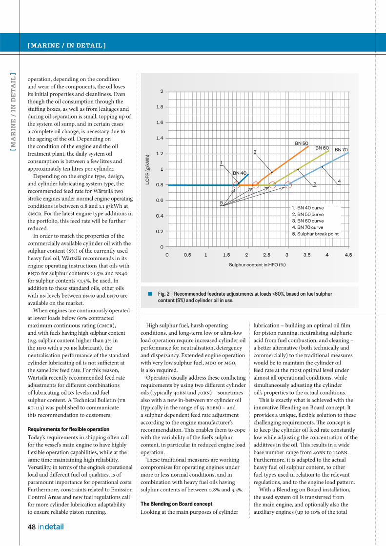
48 in detail
[ MARINE / IN DETAIL ]
[ MA
RIN
E /
IN
DE
TA
IL ]
High sulphur fuel, harsh operating
conditions, and long-term low or ultra-low
load operation require increased cylinder oil
performance for neutralisation, detergency
and dispersancy. Extended engine operation
with very low sulphur fuel, MDO or MGO,
is also required.
Operators usually address these conflicting
requirements by using two different cylinder
oils (typically 40BN and 70BN) – sometimes
also with a new in-between BN cylinder oil
(typically in the range of 55-60BN) – and
a sulphur dependent feed rate adjustment
according to the engine manufacturer’s
recommendation. This enables them to cope
with the variability of the fuel’s sulphur
content, in particular in reduced engine load
operation.
These traditional measures are working
compromises for operating engines under
more or less normal conditions, and in
combination with heavy fuel oils having
sulphur contents of between 0.8% and 3.5%.
The Blending on Board concept
Looking at the main purposes of cylinder
operation, depending on the condition
and wear of the components, the oil loses
its initial properties and cleanliness. Even
though the oil consumption through the
stuffing boxes, as well as from leakages and
during oil separation is small, topping up of
the system oil sump, and in certain cases
a complete oil change, is necessary due to
the ageing of the oil. Depending on
the condition of the engine and the oil
treatment plant, the daily system oil
consumption is between a few litres and
approximately ten litres per cylinder.
Depending on the engine type, design,
and cylinder lubricating system type, the
recommended feed rate for Wärtsilä two
stroke engines under normal engine operating
conditions is between 0.8 and 1.1 g/kWh at
CMCR. For the latest engine type additions in
the portfolio, this feed rate will be further
reduced.
In order to match the properties of the
commercially available cylinder oil with the
sulphur content (S%) of the currently used
heavy fuel oil, Wärtsilä recommends in its
engine operating instructions that oils with
BN70 for sulphur contents >1.5% and BN40
for sulphur contents <1.5%, be used. In
addition to these standard oils, other oils
with BN levels between BN40 and BN70 are
available on the market.
When engines are continuously operated
at lower loads below 60% contracted
maximum continuous rating (CMCR),
and with fuels having high sulphur content
(e.g. sulphur content higher than 3% in
the HFO with a 70 BN lubricant), the
neutralisation performance of the standard
cylinder lubricating oil is not sufficient at
the same low feed rate. For this reason,
Wärtsilä recently recommended feed rate
adjustments for different combinations
of lubricating oil BN levels and fuel
sulphur content. A Technical Bulletin (TB
RT-113) was published to communicate
this recommendation to customers.
Requirements for flexible operation
Today’s requirements in shipping often call
for the vessel’s main engine to have highly
flexible operation capabilities, while at the
same time maintaining high reliability.
Versatility, in terms of the engine’s operational
load and different fuel oil qualities, is of
paramount importance for operational costs.
Furthermore, constraints related to Emission
Control Areas and new fuel regulations call
for more cylinder lubrication adaptability
to ensure reliable piston running.
lubrication – building an optimal oil film
for piston running, neutralising sulphuric
acid from fuel combustion, and cleaning –
a better alternative (both technically and
commercially) to the traditional measures
would be to maintain the cylinder oil
feed rate at the most optimal level under
almost all operational conditions, while
simultaneously adjusting the cylinder
oil’s properties to the actual conditions.
This is exactly what is achieved with the
innovative Blending on Board concept. It
provides a unique, flexible solution to these
challenging requirements. The concept is
to keep the cylinder oil feed rate constantly
low while adjusting the concentration of the
additives in the oil. This results in a wide
base number range from 40BN to 120BN.
Furthermore, it is adapted to the actual
heavy fuel oil sulphur content, to other
fuel types used in relation to the relevant
regulations, and to the engine load pattern.
With a Blending on Board installation,
the used system oil is transferred from
the main engine, and optionally also the
auxiliary engines (up to 10% of the total
2
1.8
1.6
1.4
1.2
1
0.8
0.6
0.4
0.2
0
0 0.5 1 1.5 2 2.5 3 3.5 4 4.5
Sulphur content in HFO (%)
LO
FR
(g
/kW
h)
BN 40
1
5
2
34
BN 50BN 60 BN 70
1. BN 40 curve
2. BN 50 curve
3. BN 60 curve
4. BN 70 curve
5. Sulphur break point
Fig. 2 – Recommended feedrate adjustments at loads <60%, based on fuel sulphur content (S%) and cylinder oil in use.

WÄRTSILÄ TECHNICAL JOURNAL 01.2012
49in detail
used oil volume), and is then blended
with a specially formulated cylinder oil
additive. The result is customized cylinder
oil for each vessel’s specific operating
conditions, thus reducing a vessel’s lube
oil consumption by 10%-50%, depending
on the currently used feed rate. With the
now frequent transfer of system oil to the
blender, the vessel is able to replenish the
engine sump with fresh oil, without any
waste oil disposal, which results in a cleaner
engine and better engine performance.
Installing the Blending on Board system
The solution has been designed in a
modular way in order to allow easy
installation. The BOB system consists of
a blender with a blender control panel, and
an XRF analyzer (either with or without
the ability to detect cat fines).
The product names are:
SEA-Mate® Blender B3000
SEA-Mate® Analyzer M2000
(without cat fines detection)
SEA-Mate® Analyzer M3000
(with cat fines detection)
The system is compact enough to be
transported through a normal door. Some
modifications to the existing piping and
tank allocation are necessary, but no new
tank installations are required. The Blending
on Board system is ABS and Lloyds
Register approved.
The SEA-Mate® Blender is a compact,
robust, reliable and easy-to-use piece of
equipment, designed to fit an engine room’s
environment. It is connected to the “Used
System Oil Tank for BOB” and the “Additives
Tank” on one side, and the “Blended Cylinder
Oil Tank” and/or “Day Tank” on the other side.
The operator onboard enters the following
values on the screen of the blender control
panel:
The used system oil’s BN level – this can
be determined beforehand from
the Analyzer
The additive’s BN level – this needs to be
entered just once at the beginning, unless
a different additive product is purchased
at a later stage
The target BN level for the new batch of
blended cylinder oil – the value can be
determined from Blending on Board
instructions (and in the future will be
an integrated function in the blender
control panel)
The amount in tonnes for the new batch
of blended cylinder oil.
120
110
100
90
80
70
60
50
40
30
20
10
00.5 1 1.5 2 2.5 3 3.5 4 4.5
Ble
nd
ed
oil
BN
HFO S% content
Fig. 4 – Target BN levels for the blended cylinder oil for different fuel S%.
Fig. 3 – SEA-Mate® Blender B3000.
The cylinder lubricating oil is blended from used system oil and additives for achieving the required BN level and oil properties.
The product is based on a blender and an analyzer, which are installed onboard the vessel.
Some modifications to the existing piping and tank allocation will be necessary.

50 in detail
[ MARINE / IN DETAIL ]
[ MA
RIN
E /
IN
DE
TA
IL ]
After pushing the “Start” button, the blender
completes the required blending on its
own. Optionally, the operator can also
set the blender operation on automatic,
which will repeat the blending process with
the set values, once the blended cylinder
oil tank reaches a set minimum level.
The SEA-Mate® Blender B3000 is equipped
with all class-required features for safe
maritime operation.
The SEA-Mate® Analyzer is an integrated
part of the Blending on Board installation.
It is an advanced XRF technology based
analyzer that provides state-of-the-art
onboard or on site analysis capability for
lubricants and fuels. It also provides
the operator with a whole new level of
awareness and knowledge regarding the
importance of lubrication oil, engine
condition and monitoring. It is designed in
a robust way, gives the user clear on-screen
guidance and instructions, and provides
analysis results within only six minutes.
The analyzer is supplied together with
a bar-code reader and all required sample
bottles and bar-code labels for sampling
locations and bottles. This enables the easy
handling of sampling and provides unique
management for analysis data. The software
offers various possibilities for trending,
reporting, as well as data export.
The SEA-Mate® Analyzer is available
in two different versions. The SEA-Mate®
M2000 is designed for analyzing lubricants
and fuel sulphur only, while the SEA-Mate®
M3000 is intended for analyzing both
lubricants and fuels, and it includes the
detection and measurement of cat fines
in the fuel. Besides BN levels of lubricants,
various elements can be detected and
accurately measured in lubricants and fuels.
The XRF technology enables the detection
and measurement of total iron (Fe), which
makes the SEA-Mate® Analyzer a unique
tool, most especially in monitoring the
condition of the cylinder and piston
components, as it enables the detection
of both abrasive and corrosive wear.
The analyzers were tested in long field
tests, and measuring results from the SEA-
Mate® Analyzer were compared with results
from professional land-based laboratories
run from the same samples. The latter
comparison showed a very good correlation
(R2>0.95) between the laboratory results
and the SEA-Mate results.
Installation of the Blending on Board
system is relatively simple and can be done
without interrupting the vessel's commercial
operations. After installation of the SEA-Mate®
Fig. 6 – The principle of the Blending on Board system.
Fig. 5 – SEA-Mate® Analyzer M3000.

WÄRTSILÄ TECHNICAL JOURNAL 01.2012
51in detail
Blender and making the necessary piping
and tank adaptations, the total system is
commissioned by a senior engineer and
the crew is trained to use and operate
the blender and analyzer.
Co-operation with Maersk Fluid Technology
The Blending on Board concept and the
SEA-Mate® Blender and Analyzer products
were invented, designed and patented by
Maersk Fluid Technology (MFT), a subsidiary
of the A.P. Moeller-Maersk group. Both
the concept and the system products have,
within the past four years, been installed in
25 Maersk Line container vessels, of which
eleven have Wärtsilä two-stroke main engines.
After analyzing the technical feasibility
of the Blending on Board concept, and its
potential as a new flexible engine lubrication
management approach for the market,
Wärtsilä and MFT entered into a co-operation
agreement in the beginning of 2011 for
the joint marketing and sales of the system.
An extensive field testing and approval
process, for both the system capabilities and
the performance of various BN levels of
blended cylinder oils with different system
oils and additives, was also initiated.
Field test results
Wärtsilä followed the strict and demanding
product market introduction process
determined for oil applications. This
procedure was started by an independent
LOQUS laboratory analysis of the blended
cylinder oils, and a comparison of the
findings with the properties of commercially
available cylinder oil products. The
laboratory analysis was followed by
extensive field testing throughout 2011.
Various combinations of blended oils at
different BN levels, with different operational
loads and different fuel sulphur contents,
were tested and the condition of the piston
running components subsequently checked.
All tests were concluded successfully with
very positive impact on the engine operation
and cylinder lubrication costs. Different
cylinder oil additives from different oil
suppliers and many different operational
patterns were tested. These field test
activities have resulted in numerous
"Letters of No Objections" and the full
endorsement of the Blending on Board
concept and operation by Wärtsilä.
When operated in harsh conditions (high
sulphur content of the heavy fuel oil, low
engine load leading to lower temperatures,
high humidity in the scavenge air, etc.),
two-stroke engines are more prone to
corrosion attacking the cylinder liners and
piston rings.
To reduce the corrosion, Wärtsilä and
other engine designers recommend
increasing the cylinder lubrication oil feed
rate in order to increase the neutralisation
effect. Once the Blending on Board
equipment is in use on a vessel, the
reduction in corrosion can be achieved by
adjusting the BN of the lubricant, and not by
increasing the cylinder oil feed rate.
In one of the field tests, it was observed
that with the correct BN adjustment, and
the blended oil having a high BN level of 105,
the maximum corrosive wear was decreased
by 48%.
In addition to these effects, a fast recovery
of the engine's cleanliness was observed
after the introduction of Blending on Board
on a 9000 TEU container vessel with a
12-cylinder Wärtsilä RT-flex96C main engine.
The majority of the used system oil was
replenished with fresh system oil, and the
used oil was utilized for the blending of
the required cylinder oil. Thanks to the
Blending on Board process, the system oil
is regularly refreshed, thus keeping the system
oil in its optimal condition and the engine
components clean.
Furthermore, as regards engine
cleanliness, it was also observed that the
lifetime of the vital engine components, such
as bearings, hydraulic components in
the RT-flex system, piston crowns, etc, can
be prolonged as a result of running on fresh
system oil.
References for Blending on Board
Blending on Board has already been used
and extensively field tested for several years
on a total of 25 Maersk Line container
vessels. Based on the promising results as
described above, and the clear benefits as
summarized at the end of this article,
Maersk Line decided to rollout the concept
to another 26 vessels during 2012, all of
which are powered by Wärtsilä RT-flex96C
engines. Pilot installations for other ship
owners and a power plant are also in
the pipeline.
Wärtsilä engine lubrication management services
Along with the sole supply and installation
of the SEA-Mate® Blender and Analyzer
products, Wärtsilä is offering a variety
of services and lubrication management
concepts in order to meet the different
Fuel Sulphur Al + Si Fe Pb Cu V Ni Cr Zn Ca
M2000 X X X X X X X X X
M3000 X X X X X X X X X X
Detection range/
PPM100–60 K > 5 0–5 K
0– 1000
0– 1000
0– 1000
0– 1000
0– 1000
0– 10,000
100– 50,000
Table 1 – Detection capabilities and measurement accuracy of the SEA-Mate® Analyzers.

52 in detail
[ MARINE / IN DETAIL ]
[ MA
RIN
E /
IN
DE
TA
IL ]
Main Engine
Cylinder oil Day Tank
Cylinder oilstorage tank
(Former Cylinder oil storage tank)
BOB Additive storage tank
(Former Spare Cylinder oil tank)
BOB Base oil tank
Aux. EngineMain Engine Sump
Cylinder Oil Transfer Pump
Blending on Board unit
Fig. 7 – The layout and flow diagram of the Blending on Board system.
needs and requirements of vessel or plant
operators. Some examples include:
Analysis of an operator’s current engine
lubrication approach, performance,
consumption and overall costs, and
consulting for overall optimisation
measures
Analysis of the vessels’ piping and tank
arrangements, and the design of required
adaptations prior to the installation of
the Blending on Board equipment
Blending on Board installation,
commissioning, and crew training
Support for the technical management
in implementing the new Blending on
Board concept, including assistance in
finding the optimal cylinder lubrication
feed rate, and managing the overall
lubrication performance and costs
Analysis of trends and special findings,
and expert recommendations
Arranging the supply and supply
agreements for system oil and additives
“We consider SEA-Mate Blending on Board to be a ground breaking innovation, which will change the lubrication procedure for larger bore engines and bring significant cost savings for the operator. It will reduce cylinder oil consumption by up to 50% and reduce waste-oil volumes by up to 80%. Blending on Board will take ship-owners to the next level in terms of better engine operation, smarter lubrication management, and reducing the environmental footprint.”
"With the recent new Maersk Line BOB orders we hope to get the attention of others in shipping, as well as in other onshore industries,” says Jens Byrgesen, Managing Director of MFT, who along with technical manager, Henrik Weimar, is driving the product’s development and commercialization.
for smaller ship operators
Full engine lubrication performance
agreements, to provide continuous
optimisation of the overall lubrication
costs.
Flexible concepts
For full operational flexibility of a vessel,
Wärtsilä recommends the installation of
the complete Blending on Board system,
including the blender and analyzer.
Depending on the fleet's operating routes,
alternative concepts can be decided upon
in consultation with the customer. For
example, Wärtsilä can also provide on-the-
spot analyzing services for regular fuel and
lubricants in ports, if vessels are regularly
returning to the same port. Or, if vessels are
operated on short routes between two ports
and always bunkering the same quality
of fuel, a "blending ashore" service can be
set up by the operator or by Wärtsilä.

WÄRTSILÄ TECHNICAL JOURNAL 01.2012
53in detail
Summary of customer benefits
Technical benefits
Obtaining the optimal constant low
cylinder oil feed rate by variable BN
blending, matching the fuel sulphur
content
Just-in-time onboard production
of the correct, fit-for-purpose,
cylinder oil
Controlled cylinder liner and
rings wear during harsh operating
conditions, such as slow steaming
Engine “cleanliness” and reduction
of deposits (crankcase, liners, piston
rings, servo) due to the regular
replenishment of new system oil
in both the main and auxiliary engines
Reducing maintenance
and the need for oil separator
discharging
Reduced frictional losses with positive
effects on fuel oil consumption
Up to 1% improvement
Improved environmental footprint
due to reduced lube oil consumption
and the reduction of waste oil volumes
Lower harmful particulate
emissions and up to 80% less waste oil.
300
250
200
150
100
50
00 15 30 45 60 75
Load % CMCR
Fe
(pp
m)
–17%
–48%
BOB 79 BN BOB 105 BN
Total Iron content of piston underside drain oil during operation with BOB cylinder lubricant.
Fig. 8–9 – Condition without BOB. Fig. 10–11 – Condition with BOB installed.
Fig. 12 – During a field test on a 12-cylinder Wärtsilä RTA96C engine at different loads, the correct level of BN in the blended cylinder oil resulted in substantial reductions of corrosive wear.

54 in detail
[ MARINE / IN DETAIL ]
[ MA
RIN
E /
IN
DE
TA
IL ]
Estimated savings and payback times per year with Blending on Board:
For the below case calculation, the following parameters were used:
Engine type 7-cylinder Wärtsilä RT-flex96C
Yearly running hours 6000
Cylinder lubrication system (CLU3 or CLU4) CLU3
Average engine load 50%
Cost standard system oil (USD/t) 1550
Cost standard cylinder oil (USD/t) 2000
Cost additives (BP, XOM, PC) (USD/t) 3500
Cost fuel price (USD/t) 600
Areas of cost savingsApprox. savings in USD/year
Cumul. Savings in USD/year
Payback times in years
Annual savings from cost difference between standard cylinder oil and blended cylinder oil and from reduced feed rate (0.1 g/kWh assumed)
110,000130,000 < 2.5
Annual savings from reduced system oil losses through separator discharging, due to extended discharge intervals
20,000
Annual savings from reduced maintenance and spare parts costs due to better component condition and TBOs
50,000 180,000 < 2.0
Annual fuel savings of 0.5% due to impact of reduced friction and optimal viscosity coming from frequent replenishment of system oil and cleaner engine.
60,000 240,000 < 1.5
Commercial benefits
Producing blended cylinder oil from
used system oil plus additives results in
lower total costs compared to using
commercial cylinder oils
Re-cycling of used system oil, instead of
disposing of it, reduces overall lube oil
consumption and BN usage
Less separator discharges, thus additional
savings
Bunkering additives for a longer period
of operation creates operational flexibility,
as there is no need to buy commercial
cylinder oil in expensive ports. Improved
supply security by the sourcing of
system oil.
Payback time on investment is usually
within 2 years, depending on engine type
and operating conditions.
In addition to the overall Blending on
Board concept benefits, the SEA-Mate®
Analyzer provides the following benefits:
Early wear detection (liner scuffing) with
access to wear metal, cat fines (M3000)
and BN information
Supports the Blending on Board
process, feed rate optimisation and
TBO extensions
Analysis of HFO for cat fines and fuel
sulphur level (confirm HFO prior to
bunkering)
Supports the Blending on Board
process and operation of the fuel
treatment plant
Analysis results generated in 6 minutes
Quick support, reduced external oil
analysis costs
Analysis that includes all lubricated
systems (maneuvering systems,
ancillaries)
Quick support, and reduced
external oil analysis costs
Analysis of used lube oil and fuel oil
can be done onboard instead of using
laboratory services
Reduced external oil analysis costs
Ability to trace each sample point’s
history, and to forecast problems by
observing trends
Supporting professional
lubrication management
Ability to confirm lube and fuel separator
efficiency through cat fine measurements
(M3000)
Support for improved performance,
discharges and maintenance can
be carried out when needed
Measurement of key elements (Ca, V, Cr,
Fe, Ni, Cu, Zn, Pb, S). Cat fines detection
only with the Analyzer SEA-Mate® M3000
tests Si and Al down to 5ppm combined.
Cylinder oil feed rate reduced to a
minimum, thanks to the ability of
knowing the true iron wear in the
cylinder. The XRF analyzer allows
continuous monitoring of various engine
fluids, including the analysis of true Fe
content; both corrosive and abrasive
iron wear.
Example of a customer business case
Customer specific business case calculations can be made by providing the customer’s installation
and operational parameters. The following influencing parameters can be considered in the
calculations on a monthly basis: fuel sulphur level, engine load, current used cylinder oil BN,
current used cylinder oil feed rate, current price levels for system and cylinder oils:

WÄRTSILÄ TECHNICAL JOURNAL 01.2012
55in detail
New environmental regulations relating to operating within Emission Control Areas (ECAs) come into effect in 2015. The marine industry is actively seeking ways to comply. Converting to gas fuelled propulsion is an increasingly viable option.
There are a number of reasons why a gas
conversion makes sense, though customer
needs naturally vary. Such needs can be
everything from emphasizing the green
image of the company, to purely economic
reasons. However, in a majority of cases,
the main drivers for converting to gas are
the significant emission reductions,
the consequentially reduced fees, and
the reductions in fuel costs.
The year 2015 is rapidly approaching, and
with it the new emission reduction
requirements within Emission Control Areas
(ECAs). For shipowners and charterers
operating in these areas, there are mainly
three solutions available; low sulphur fuel
(MDF), SOx scrubbers, or liquid natural gas
(LNG).
The price of LNG at major import terminals
is today very cost competitive. Interest in
expanding the existing infrastructure is
vibrant, with investment proposals for small
scale LNG facilities being reported almost
daily. However, in order to build a solid
business case, the price of the fuel is the
most important parameter in the analysis.
Having an agreed LNG price level at an early
stage with a gas supplier, would remove
this uncertainty and significantly increase
the success probability of the project.
In practice, all vessels can be converted
where available space exists for the LNG tank.
Nevertheless, the prime target vessel types
can be listed as being; RoRo/RoPax, product/
chemical tankers, container vessels with LNG
containers, and bulkers.
Fig. 1 – The Bit Viking owned by Tarbit Shipping after becoming the world’s first merchant ship to undergo a LNG conversion.
LNG conversions for marine installationsAUTHORS: Sören Karlsson, General Manager, Ship Power Technology
Mathias Jansson, LNGPac Product Manager, Ship Power Technology
Jens Norrgård, General Manager, Project Proposals , S ervices
Jens Häggblom, Project Proposal Manager, S ervices

56 in detail
[ MARINE / IN DETAIL ]
[ MA
RIN
E /
IN
DE
TA
IL ]
LNG storage
A key factor for the success of a gas
conversion is finding sufficient space for
storing the gas onboard the vessel. Wärtsilä
has developed tools for calculating the
required dimensions and weights in order
to find an optimal solution. Conceptual, as
well as in depth, studies can be made based
on customer requests. For the Wärtsilä gas
engine portfolio, gas storage in the form of
LNG can be considered the most attractive
alternative due to the high energy density
of LNG and, therefore, the relative
compactness of the storage required.
Currently, LNG is also being developed for
use in road vehicles, with considerable
less installed power, and it can be
anticipated that LNG will increasingly
dominate the marine market.
Daily gas consumption can easily be
calculated based on the existing operating
profile. In order not to incur unnecessarily
high capital costs, the LNG storage tank
should be kept as small as possible and
instead more frequent bunkering intervals
should be considered. The existing liquid
fuel storage system would continue to work
as a backup system if necessary.
The LNG storage location can be freely
selected onboard the vessel, and either
vertical or horizontal tanks, on open deck or
below deck, can be selected. When storage
is above deck, the requirements set by the
classification societies are slightly lower.
Additionally, for the conversion, installation
on an open deck is very straightforward,
and some of the system ventilation
requirements can be circumvented.
The LNG storage tanks and any additional
steel structures may have an impact on
the vessel’s stability. These vessel stability
criteria, with new LNG tanks installed, can
be analysed in-house by Wärtsilä as part of
the initial feasibility study. For vessels with
a very high stability, the rolling behaviour
and crew comfort can even be improved.
Converted or new engines?
The second step in the process is to check
whether or not the existing engines onboard
can be converted, or if they should be
exchanged for new Wärtsilä dual-fuel
engines. Generally speaking, converting
an existing engine is recommended and is
economically more feasible than installing
new ones - especially when keeping in mind
that a conversion basically brings the same
benefits as new engines. For example, the
same warranty is granted as for a brand new
engine, in addition to which there are also
savings to be made on maintenance costs
since the running hours are reset. However,
with smaller generating sets, say below 2 MW,
it might be more cost effective to install
new engines.
At present a conversion can be offered for
basically all Wärtsilä 32, Vasa 32 and
Wärtsilä 46 engines.
Wärtsilä is actively considering
expanding its portfolio of conversions,
and in the future it may even be possible
to convert two-stroke engines.
If the existing engines aren’t suitable for
conversion, the only option is to replace
them with new ones. When doing this
one may need to replace the gearbox
and some of the auxiliary equipment as
well, should it prove that the capacity of
the existing equipment isn’t sufficient.
Unless it’s a question of replacing old
engines with new ones, a DF-conversion
will usually mean a lowering of the total
output onboard. If the utilisation of the
available power onboard is normally
in the lower range, this is in most cases
acceptable. In other cases it may prove to
be quite critical and has to be compensated
for in some way, like for instance,
omitting the use of shaft generators.
Another important consideration is,
of course, the age of the installation. A
DF-conversion is a fairly large investment,
and if the vessel is near the end of its
service life, there is a big risk that a
conversion would never pay itself back.
From vision to offer
Developing a LNG conversion solution, from
a vision to a completed project, will involve
a number of progressive steps. We have,
therefore, made a model of how to handle
the Proposal Management (see Figure 2).
MARINE LNG SALES PROJECT DEVELOPMENTStructure of offering (sales) process
RFP (Request for Proposal)
RFP from client
Leads / Opportunities developed with the client
Pre-study
Concept study from GA drawings and data provided by client
Budgetary proposal for equipment delivery.
Go / No Go decision
Pre-study follow up
Possible ship check
Possible update of budgetary proposal
Preliminary time schedule Go / No Go decision
Agreement on feasibility and basic design
Feasibility
Broad engineering, design work and report for determining feasibility
Engineering package for submittal to the flag authorities and class society for concept approval Go / No Go decision
Basic design
Build plan and schedule in cooperation with client
Engineering deliverables needed to secure a ship- yard contract
Turn key proposal preparation
Obtaining firm offer from selected ship- yard and other sub suppliers
Preparation of turn key proposal
Preparation of contract draft
Presentation of proposal
Submittal and presentation of detailed proposal and contract draft
Fig. 2 – Typical lead times for the major tasks in the sales process.
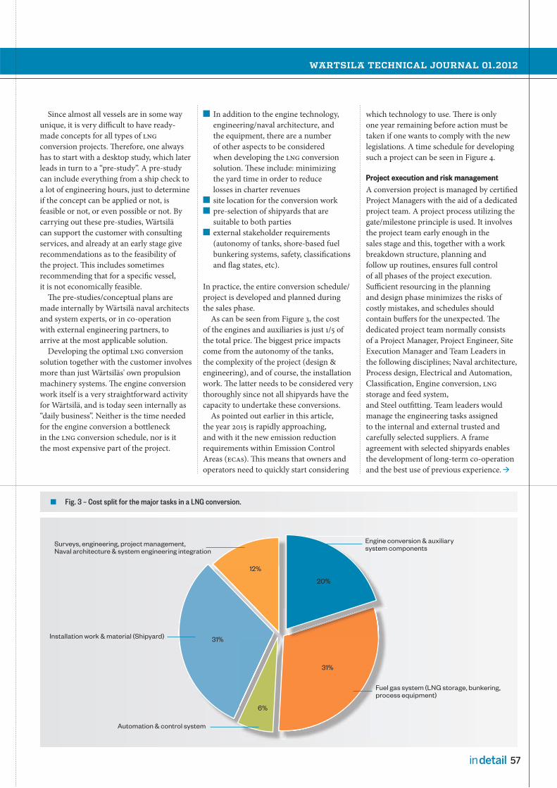
WÄRTSILÄ TECHNICAL JOURNAL 01.2012
57in detail
Since almost all vessels are in some way
unique, it is very difficult to have ready-
made concepts for all types of LNG
conversion projects. Therefore, one always
has to start with a desktop study, which later
leads in turn to a “pre-study”. A pre-study
can include everything from a ship check to
a lot of engineering hours, just to determine
if the concept can be applied or not, is
feasible or not, or even possible or not. By
carrying out these pre-studies, Wärtsilä
can support the customer with consulting
services, and already at an early stage give
recommendations as to the feasibility of
the project. This includes sometimes
recommending that for a specific vessel,
it is not economically feasible.
The pre-studies/conceptual plans are
made internally by Wärtsilä naval architects
and system experts, or in co-operation
with external engineering partners, to
arrive at the most applicable solution.
Developing the optimal LNG conversion
solution together with the customer involves
more than just Wärtsiläs' own propulsion
machinery systems. The engine conversion
work itself is a very straightforward activity
for Wärtsilä, and is today seen internally as
“daily business”. Neither is the time needed
for the engine conversion a bottleneck
in the LNG conversion schedule, nor is it
the most expensive part of the project.
In addition to the engine technology,
engineering/naval architecture, and
the equipment, there are a number
of other aspects to be considered
when developing the LNG conversion
solution. These include: minimizing
the yard time in order to reduce
losses in charter revenues
site location for the conversion work
pre-selection of shipyards that are
suitable to both parties
external stakeholder requirements
(autonomy of tanks, shore-based fuel
bunkering systems, safety, classifications
and flag states, etc).
In practice, the entire conversion schedule/
project is developed and planned during
the sales phase.
As can be seen from Figure 3, the cost
of the engines and auxiliaries is just 1/5 of
the total price. The biggest price impacts
come from the autonomy of the tanks,
the complexity of the project (design &
engineering), and of course, the installation
work. The latter needs to be considered very
thoroughly since not all shipyards have the
capacity to undertake these conversions.
As pointed out earlier in this article,
the year 2015 is rapidly approaching,
and with it the new emission reduction
requirements within Emission Control
Areas (ECAs). This means that owners and
operators need to quickly start considering
which technology to use. There is only
one year remaining before action must be
taken if one wants to comply with the new
legislations. A time schedule for developing
such a project can be seen in Figure 4.
Project execution and risk management
A conversion project is managed by certified
Project Managers with the aid of a dedicated
project team. A project process utilizing the
gate/milestone principle is used. It involves
the project team early enough in the
sales stage and this, together with a work
breakdown structure, planning and
follow up routines, ensures full control
of all phases of the project execution.
Sufficient resourcing in the planning
and design phase minimizes the risks of
costly mistakes, and schedules should
contain buffers for the unexpected. The
dedicated project team normally consists
of a Project Manager, Project Engineer, Site
Execution Manager and Team Leaders in
the following disciplines; Naval architecture,
Process design, Electrical and Automation,
Classification, Engine conversion, LNG
storage and feed system,
and Steel outfitting. Team leaders would
manage the engineering tasks assigned
to the internal and external trusted and
carefully selected suppliers. A frame
agreement with selected shipyards enables
the development of long-term co-operation
and the best use of previous experience.
Surveys, engineering, project management, Naval architecture & system engineering integration
Installation work & material (Shipyard)
Automation & control system
Engine conversion & auxiliary system components
Fuel gas system (LNG storage, bunkering, process equipment)
l system
Fuelproc
Enginesystem
12%
6%
20%
31%
31%
Fig. 3 – Cost split for the major tasks in a LNG conversion.

58 in detail
[ MARINE / IN DETAIL ]
[ MA
RIN
E /
IN
DE
TA
IL ]
2012 2013 2014 2015
Q1 Q2 Q3 Q4 Q1 Q2 Q3 Q4 Q1 Q2 Q3 Q4 Q1 Q2 Q3 Q4
Vision
RFP
Desktop study
Pre-study
Concept development
Contract negotiations
Signing of contract
Project lead time
Deadline Q1/2015
Fig. 4 – A typical project schedule, including a zoom of the actual conversion schedule.
Engineering, design, planning
Manufacturing
Piping, cabling, equipment installation, hull modifications
Engine conversion
Commissioning test run & sea trial
LNG conversion time schedule(Typical for a single main engine merchant vessel, starting from date of order)
0 5 10 15 20 25 30 35 40 45 50 55 60 65
Weeks
Duration

WÄRTSILÄ TECHNICAL JOURNAL 01.2012
59in detail
During the conversion, the most effective
work division between the yard and
Wärtsilä is that both parties focus on their
own key competence areas, and together
work towards finalising the conversion.
Interface handling between the different
parties is crucial for the success of a
conversion, due to the short lead time
involved. Therefore, detailed and defined
specifications and areas of responsibility are
the key to a successful engineering result. A
document management system that is open
and available for all involved engineering
parties enables revision handling and better
interface communications. Engineering
review meetings with subcontractors, the
yard and the customer, guarantees that no
additional change requests to the design
appear during the actual installation work
at the yard.
Laser scanning of the vital parts of the
vessel can be recommended if the added
values are seen as being crucial. Scanning of
the structure is dependent on the available
drawings and CAD models of the vessels.
The classification and quality assurance
of all engineering work and equipment
installed in a conversion is the responsibility
of the project team working closely with
the classification societies. Classification
requires a project specific Failure Mode and
Effects Analysis (FMEA). The HAZOP or FMEA
would be based on the already available
FMEAs of the engine and gas fuel feed
system. During the project execution, close
co-operation with the classification society
is crucial in order to ensure that all class
requirements are met and fulfilled as a result
of the conversion. The Wärtsilä project team
carries total responsibility for ensuring
that all equipment installed has the correct
quality assurance, material certificates,
and Non Destructive Testing (NDT).
Any required SOLAS update would be
the responsibility of the owner of the ship.
Training of the crew and ship owners, as
required by the classification society, can
be carried out by the training experts at
the Wärtsilä Land and Sea Academy.
The conversion work at the yard is
managed by the site manager, who is part
of the project team. Further to the actual
installing of all new equipment
commissioning, the quay and sea trials
of the vessel are the responsibility of
the site manager.
Tailoring a service agreement
After conversion, the propulsion train can
be operated as normal. However, Wärtsilä
can also offer improved reliability and
assistance based on the customer’s needs
and preferences. By teaming up as partners
at an early stage, maintenance schedules can
be jointly developed, which often results in:
Improved reliability and availability
- ‘what we can measure we can manage’.
Extended maintenance schedules,
but in a controllable way.
Optimisation of the maintenance
planning and execution - doing the
maintenance at the right time and place
to ensure economic benefits
(lifecycle management).
Reduced risk exposure for the customer.
Long term savings in Operation &
Maintenance costs due to improved
lifecycle costs.
Improved fuel consumption as an
additional plus from assuring optimal
running values.
As a reference, it can be mentioned that
the majority of the LNG carrier operators
with dual-fuel engines onboard have service
agreements with Wärtsilä to ensure improved
and stable revenue flows from their
investment.
Case study and references
Wärtsilä performed the first conversion of
a marine vessel from heavy fuel oil (HFO) to
liquefied natural gas (LNG) operation when
the MT Bit Viking was converted in 2011.
The total scope included the installation of
two 500 m3 LNG fuel storage tanks (LNGPac)
on the ship’s deck, converting the two
existing Wärtsilä 46 engines to Wärtsilä 50DF
engines, the installation of two LNG
Fig. 5 – LNG tanks and components required for a LNG conversion.
Complete
vessel conversion:
Engine conversion
LNG tank(s) and
foundation
LNG/NG double
walled piping
Gas detection
and fire suppression
Inert plant/N2 storage
and control air
Bunkering station(s)
Automation and
control system
Exhaust pipe gas
burst disc(s)

60 in detail
[ MARINE / IN DETAIL ]
[ MA
RIN
E /
IN
DE
TA
IL ]
bunkering stations, all the LNG and gas
piping onboard, updating the vessel’s
automation, and the gas detection system.
Furthermore, the classification documents
were updated as required. This included,
among other things, updating the stability
handbook and docking plane. The vessel
was handed back to the owner after
successful quay and sea trials.
The project started in the summer of 2010
with the signing of the project contract.
The engineering, procurement, and
manufacturing started immediately thereafter
and continued into the summer of 2011. The
conversion work was finalised in autumn of
2011, and the project was completed in
October 2011. The conversion of the engines
to DF operation was carried out in just six
weeks.
Since 2005, Wärtsilä has converted 40
diesel engines to dual-fuel engines in land
based power plants around the world.
A Wärtsilä 50DF engine has already
accumulated more than 40,000 operating
hours following a conversion. The Bit Viking
engine conversion was Wärtsilä's first marine
engine to be converted to dual-fuel operation.
CONCLUSIONS
The key driver in the increasing interest in
LNG as a marine fuel, on a global level, is
the increased focus on reducing emissions.
In whichever way the customer prefers to
address future trends regarding fuel prices
or emission abatement methods, Wärtsilä
can meet such needs for both new buildings
as well as gas conversions. A documented
way of working, and means of handling the
complex tasks and processes efficiently, have
been developed and are continuously being
improved. An already established track
record of completed turnkey conversion
projects is available, including the SOX
scrubber conversion of the Containership
VII vessel, and the LNG conversion of the
Bit Viking. The long-term commitment
to this strategy can be further exemplified
by the acquisition of Hamworthy to add
even greater strength to the company’s
environmental capabilities. The lead time
from idea to completion may require up
to one and a half years, and starting such
discussions in good time is essential if the
potential 2015 deadline is to be met.
Fig. 6 – Lifting of the LNG tanks aboard the Bit Viking during the conversion.

WÄRTSILÄ TECHNICAL JOURNAL 01.2012
61in detail
The Wärtsilä 32 engine is now available with improved performance. It features best-in-class power density and fuel economy across a broad operating range. Its rated power is 15 percent greater than before.
The upgraded Wärtsilä 32 is now available
in the 6, 8 and 9 cylinder in-line series,
and the 12 and 16 cylinder V series. It
produces 580 kW/ cylinder at 750 rpm,
while the total rated engine output
ranges between 3.5 and 9.3 MW.
Its excellent fuel flexibility allows the
Wärtsilä 32 to operate on heavy fuel oil
(HFO), light fuel oil (LFO) and liquid bio fuel
with a broad range of fuel viscosities, from
2.0 cSt up to 730 cSt HFO (at 50 °C/122 °F).
The engine is able to operate efficiently and
economically on low sulphur fuel oils
(<0.1% S), making it suitable for operation
in emission-controlled areas.
It fulfils the IMO Tier II regulations as set
out in Annex VI of MARPOL 73/7. It can also
be equipped with a Selective Catalytic
Reduction (SCR) catalyst, such as the
Wärtsilä Nitrogen Oxide Reducer (NOR).
This means that, already today, the engine
is IMO Tier III compliant.
Background
The cylinder output of the Wärtsilä 32 engine
has been increased six times since 1980. In
1980, the first 32 engine had 308 kW/ cylinder,
while the current version has 500 kW/
cylinder at 750 rpm.
For more than 30 years, Wärtsilä 32 bore
engines have been the preferred choice of
yards, operators and owners, with more
than 4000 engines having been delivered
to the marine market alone. It has a proven
track record in a wide range of vessel
applications, including as a main engine,
both direct mechanical drive as well as
diesel electric, and as an auxiliary engine.
It can be optimised for either constant
speed or along a combinatory curve.
In the merchant fleet, its’ typical
applications include use as the main engine
on different types of tankers and container
vessels. In the offshore sector, the reliability
of the Wärtsilä 32 has made it the most
popular medium-speed engine Fig. 1 – After the latest upgrade, the Wärtsilä 32 has the best performance in the market .
The Wärtsilä 32 engine – making the good even better AUTHORS: Asko Vakkila, Manager, Product Information
Mika Harjamäki, Product Manager, Wär tsi lä 32

62 in detail
[ MARINE / IN DETAIL ]
[ MA
RIN
E /
IN
DE
TA
IL ]
for offshore service vessels and drilling
vessels. Similarly, in the cruise and ferry
sector, the Wärtsilä 32 has proven to be
the most favoured engine of its size. In
auxiliary electric production, the Wärtsilä
32 is widely utilized in all vessel categories
where high auxiliary load is needed.
Project and schedule
The upgraded Wärtsilä 32 is based on the
same well-proven technology and design
principles as the current Wärtsilä 32 engines.
It is a turbo-charged 4-stroke diesel engine
with direct fuel injection and charge air
cooling. The cylinder bore is 320 mm and
the stroke is 400 mm.
Because the basic technology was already
in place, the project proceeded very rapidly.
Development began after official approval in
October 2009, and the first 6-cylinder proto
engine was started successfully at the Vaasa
factory’s test run cell in September 2010.
The project proceeded on schedule and
within the budget.
The Wärtsilä 32 pilot sales release took
place in November 2010 and the first
customer order was received in April 2011.
The Type- and Engine International Air
Pollution Prevention (EIAPP) tests with
classification societies were completed
by the end of September 2011.
Assembly of the first pilot engines began
during August and the testing was
completed at the Vaasa factory by the end
of October 2011. The Ship Power business
unit took delivery on 19 October 2011.
The project itself was closed in the end of
January 2012.
Design and development
It was clear from the start that the most
suitable way to improve the power density
and product cost ratios was to increase the
firing pressure. For this, it was necessary
to optimise the combustion and to utilize
the latest high efficiency turbo charging.
The firing pressure has been increased from
21 MPa to 23 MPa.
However, while increasing the firing
pressure, it was also necessary to ensure
that the engine’s proven reliability was
maintained and that the prospective
commonality with gas engines could be
ensured. This meant the redesign of several
smaller and bigger components. Great
attention has also been paid to the noise and
exhaust gas, both of which are important
environmental aspects.
Main components
The engine block is based on the proven
design of the established Wärtsilä 32, with
the cylinder head bolts’ thread size being
increased from M56 to M60. The bore for
the cylinder liner is increased to enable
the future usage of a gas engine´s cylinder
liner with larger cylinder bore (340 mm).
The camshaft bearing diameter has been
increased from 190 mm to 230 mm and
the centreline is moved 20 mm downwards
to give more space for better serviceability.
The cam profiles are new and performance
has been optimised.
The cylinder head casting is common to
that of the gas engines. The design has been
strengthened in many ways, for example
by improving the flame plate. Great
attention has also been paid to easing the
serviceability. The crankshaft has a new
strengthened design with thicker crank
webs. The engine covers have improved
noise reduction and are common with those
for gas engines. The connecting rod design
is the same three-piece design, known as
Fig. 2 – The proto engine being started in a test run in Vaasa, Finland.

WÄRTSILÄ TECHNICAL JOURNAL 01.2012
63in detail
the “marine-design”, as with the former
Wärtsilä 32, but the material has been
changed and is now harder than before.
The three-piece design reduces the
height required for piston overhauling.
A piston overhaul is possible without
touching the big-end bearing, while the
big-end bearing itself can be inspected
without removing the piston.
Fuel injection system
The conventional fuel injection system
has been upgraded with increased fuel
injection pressure and volume. The Wärtsilä
32 engine is designed for continuous
operation on HFO as well as LFO. A pre-
heated engine can be started directly on
HFO provided that the external fuel system
has the correct temperature and pressure.
Charge air and exhaust gas systems
Due to the increased charge air pressure
ratio and efficiency, a new version of
turbochargers has been introduced.
Both turbocharger types are connected
to the engine lubricating oil system. The
re-designed charge air cooling system
provides better engine performance
and commonality with gas engines.
The exhaust system will remain quite
the same as earlier, and the exhaust waste
gate/ by-pass system design is identical
with the one that is used in gas engines.
For offshore sector use, a design having a
charge air blocking device will be available.
The various changes to the charge
air system, as shown above, have led
to a new design for the insulation
box, heat- and noise coverings.
Fig. 4 – The fuel injection system in a hot-box (pump shelf).
Fig. 3 – Wärtsilä 32 cylinder head is now stronger and easier to service.

64 in detail
[ MARINE / IN DETAIL ]
[ MA
RIN
E /
IN
DE
TA
IL ]
Starting air system
The starting air system has also had several
new improvements due to the standard
installed slow turning system, a new main
starting valve, and the turning device. The
overall functional speed of the system
is faster. Great attention has been paid
to ease of assembly and thus also to the
serviceability, and last but not least, to a
strong commonality with gas engines.
Automation
The UNIC C2 engine control system is
used on the upgraded engine without
major changes. However, some of the
features that were optional earlier, are now
available as standard. These include:
engine slow turning
temperature monitoring systems for
cylinder liners and big end bearings.
The UNIC C2 automation system is an
embedded engine management system.
The system is specifically designed for
the demanding environment associated
with engines, thus the design pays special
attention to temperature and vibration
endurance. This allows the system to be
directly mounted on the engine, which
allows for a very compact design without
requiring the components to be mounted in
dispersed external cabinets or panels. It also
allows the engine to be delivered fully tested
at the factory. Thanks to the pre-tested
configuration, the engine or generating
set can be operational with a minimum of
commissioning and installation work.
The modular and standardized interface
provides the designer of the off-engine
automation systems with an easily re-usable
design. For example, it allows the conversion
of diesel engines to dual-fuel or common
rail with a minimum of modifications.
The critical parts of the UNIC system are
either redundant or very fault-tolerant to
guarantee high safety and availability in all
circumstances. In particular, parts like the
communication and power supply are fully
redundant to allow single failures without
interruptions to the engine’s operation.
Validation and performance
Testing of the Wärtsilä 32 started in
September 2010, when the fist proto 6-
cylinder in-line Wärtsilä 32 engine was
delivered from the factory. The official
start up of the engine was arranged
for the very next morning after the
engine was put in the test cell.
The engine was already performing
well with the first specification, and full
output was reached the same day as the
official start. The engine was moved to
the engine laboratory in October.
When testing began, the main focus
was on optimising engine performance
for constant speed applications. The target
was to have values for the performance
manual before the end of October. The
time schedule was tight but nevertheless,
the values were given to the product
engineering project team before the
deadline. The fuel consumption, emissions
and thermal load were according
to expectations. A load acceptance
optimisation test was also performed in
order to reach the 3-step loading target.
Testing continued until the beginning of
2011 with product validation tests, such as
vibration, stress, temperature and pressure
pulse measurements. To achieve extended
maintenance-free operation - and with it
maximized revenue-earning capability – it
is vital to get the best possible knowledge
about the components concerned.
After these optimisation and validation
tests, it was time to perform an endurance
Fig. 5 – The Wärtsilä 32 from the rear. Fig. 6 – The control system is the brain of the engine.

WÄRTSILÄ TECHNICAL JOURNAL 01.2012
65in detail
test on the Wärtsilä 32 engine.
The first 1000 hours endurance test
at an output of 580 kW/ cylinder was
completed just before midsummer in 2011.
Currently, the laboratory engine has
accumulated close to 2250 running hours,
with another 1500 more hours expected
before the end of 2012.
Based on these experiences, we can
proudly say that the Wärtsilä 32 engine
performs excellently, and is a world-class
performer amongst 32 bore size engines.
The target of developing the most powerful
engine in its class has been achieved.
Benefits to the customer
As already stated earlier, Wärtsilä 32 bore
engines have been the preferred choice of
yards, operators and owners since the 1980s.
As from 2012, the upgraded Wärtsilä 32
continues that tradition.
The main drivers for the design were
high power density, product costs and
commonality with gas engines. In simple
terms, this means more power with fewer
cylinders to overhaul.
The engine is designed for long periods
of maintenance-free operation and has
overhaul intervals of up to 24,000 hours
with low consumption of spares. This, and
the maintenance-friendly design, serves to
reduce downtime, promote scheduling, and
cut operating costs. Together with dynamic
maintenance planning and service
agreements, the overhaul interval time for
the Wärtsilä 32 can be extended even further,
thus minimizing maintenance costs and
maximizing the revenue-earning capability
of the vessel.
The Wärtsilä 32 has been designed to
operate reliably on a range of fuels, including
HFO, MDO and liquid bio fuels, and even with
the poorest quality of heavy fuel. In all cases
it has shown proven reliability, high power
density, and low fuel consumption over
a wide load range. Additionally, the high
degree of commonality with gas engines
makes future conversions to, for example,
dual-fuel very easy.
Constant development and the search for
improvement are central to Wärtsilä's
philosophy as a total solutions provider. In
making the Wärtsilä 32 engine even better
than it is already, this strategy is once again
emphasised. At the same time, Wärtsilä's
industry leading global support network
is being similarly enhanced and broadened
to ensure full lifecycle support for its
customers' installations.
REFERENCE: Bergen, Norway
The Wärtsilä 32 engine with extra power output is introduced
The VS 465 is equipped with the upgraded Wärtsilä 32 engine.
The Bergen Group's BMV shipyard in Norway is to build a Wärtsilä VS 465 design vessel for Atlantic Offshore, part of the Atlantic Maritime Group. Included in the order is the complete diesel electric propulsion system from Wärtsilä, comprising 6-cylinder in-line Wärtsilä 32 and 20 (two of each) generating sets, the electric and automation systems, the frequency drives, the gear and controllable pitch propeller, the tunnel thrusters, as well as a retractable thruster. This will be the first installation of the upgraded Wärtsilä 32 engine with its power output increased from 500 to 580 kW/cylinder. While the external dimensions remain unchanged, this represents a power increase of 15 percent over the earlier version of the
engine, which was originally introduced in the 1980s. The Wärtsilä 32 now covers a power range from 3 MW to 9.3 MW. In the VS 465 vessel, the needed cylinder output is 550 kW/cylinder at 720 rpm and the total rated output per engine is 3300 kW. The total rated mechanical output of the main diesel generating sets (2 x Wärtsilä 32) is 6600 kW.
The new ship will also feature Wärtsilä’s Low Loss Concept (LLC), a proven energy efficient and highly redundant power distribution system for electric propulsion applications. The combination of the higher engine output and LLC means that fuel consumption and exhaust gas emissions will be minimized.

Time
GW


90°W 45°W 0°
75°N
45°N
0°
45°S
45°E 90°E 135°E
WÄRTSILÄ NETWORK
...
in detailWÄRTSILÄ TECHNICAL JOURNAL | WWW.WARTSILA.COM
The information in this magazine contains, or may be deemed to contain “forward-looking statements”. These statements might relate to future events or our future financial performance, including, but not limited to, strategic plans, potential growth, planned operational changes, expected capital expenditures, future cash sources and requirements, liquidity and cost savings that involve known and unknown risks, uncertainties and other factors that may cause Wärtsilä Corporation’s or its businesses’ actual results, levels of activity, performance or achievements to be materially different from those expressed or implied by any forward-looking statements. In some cases, such forward-looking statements can be identified by terminology such as “may,” “will,” “could,” “would,” “should,” “expect,” “plan,” “anticipate,” “intend,” “believe,” “estimate,” “predict,” “potential,” or “continue,” or the negative of those terms or other comparable terminology. By their nature, forward-looking statements involve risks and uncertainties because they relate to events and depend on circumstances that may or may not occur in the future. Future results may vary from the results expressed in, or implied by, the following forward-looking statements, possibly to a material degree. All forward-looking statements made in this publication are based only on information presently available in relation to the articles contained in this magazine and may not be current any longer and Wärtsilä Corporation assumes no obligation to update any forward-looking statements. Nothing in this publication constitutes investment advice and this publication shall not constitute an offer to sell or the solicitation of an offer to buy any securities or otherwise to engage in any investment activity.