2012 cnt fuel cell
DESCRIPTION
CNTFUEL CellsTRANSCRIPT

Sd
SJa
b
c
d
e
f
a
AA
KMCPCG
1
nAcbocam
w[maatt
J
0d
Sensors and Actuators A 177 (2012) 30– 36
Contents lists available at SciVerse ScienceDirect
Sensors and Actuators A: Physical
journa l h o me pa ge: www.elsev ier .com/ locate /sna
tructural optimization of contact electrodes in microbial fuel cells for currentensity enhancements
hogo Inouea,f,∗, Erika A. Parrab,f, Adrienne Higaf, Yingqi Jiangf, Pengbo Wangc,f, Cullen R. Buied,f,ohn D. Coatese, Liwei Lin f
Microdevice Research & Development Department, TAIYO YUDEN CO., LTD., JapanDepartment of Organismic & Evolutionary Biology, Harvard University, USACollege of Engineering, China Agricultural University, ChinaDepartment of Mechanical Engineering, Massachusetts Institute of Technology, USADepartment of Plant and Microbial Biology, University of California at Berkeley, USABerkeley Sensor and Actuator Center, Department of Mechanical Engineering, University of California at Berkeley, USA
r t i c l e i n f o
rticle history:vailable online 22 September 2011
eywords:icrobial fuel cell
a b s t r a c t
More than 200% current density enhancement in miniaturized microbial fuel cells (MFCs) has been suc-cessfully demonstrated by optimizing the contact electrode structure using micro and nano features. Twofundamental issues are addressed in this work: (1) a methodology to enhance current/power density ofMFCs by changing micro and nano structural configurations of contact electrodes and (2) a study on the
urrent densityower densityarbon nanotubeeobacter sulfurreducens
effectiveness of charge transfer between living cells with organic nanowire-pili and micro/nano inter-facial electrodes. This paper details the fabrication and characterization processes of miniaturized MFCswith experimental results, and discusses the prospective power density of MFCs using micro/nano pro-cesses. Moreover, a hypothesis for the direct electron transport mechanism from living cells to electrodesis experimentally corroborated. As such, this work represents a step toward higher energy conversionefficiency as well as practical applications of MFCs.
. Introduction
Compact and highly efficient power sources are integral compo-ents for the completion of autonomous sensors and microsystems.
microbial fuel cell (MFC) is a promising candidate for electri-al energy harvesting from ubiquitous organic wastes [1]. Thereakdown of organic substances to retrieve energy is a naturallyccurring process in nature and the possibility to extract electri-al charges in the form of MFCs holds great potential in practicalpplications such as implantable medical sensors and long-termonitoring systems in remote locations.Recently, �L-scale MFCs fabricated with MEMS technologies
ere demonstrated using Geobacteraceae [2] and Shewanellaceae3] as the organic catalysts that break down reduced carbon
olecules during the metabolic process. Previously, our group haslso reported miniaturized MFCs which use baker’s yeasts [4,5]
nd Geobacter sulfurreducens [6] as the bio-catalysts. A photosyn-hetic electrochemical cell has also been presented that harnesseshe subcellular thylakoid photosystems isolated from spinach cells∗ Corresponding author at: 64, Nishiwaki, Ohkubo-cho, Akashi, Hyogo 674-8555,apan. Tel.: +81 78 937 1270; fax: +81 78 937 1271.
E-mail addresses: [email protected], [email protected] (S. Inoue).
924-4247/$ – see front matter © 2011 Elsevier B.V. All rights reserved.oi:10.1016/j.sna.2011.09.023
© 2011 Elsevier B.V. All rights reserved.
to convert light energy into electricity [7]. In general, electronswere extracted during these biological processes to provide elec-tricity. Electron mediators have been used to extract electrons andprotons from cells or sub-cellular components (to be referred toas “sub-cell” hereafter) in engineering fuel cell systems. Electronsare transported externally via a conducting electrode (anode), andprotons are transported through a proton-exchange-membrane(PEM) and reduce the oxidant in the cathode compartment. Theefficiencies of these MFCs are low due to many loss mechanisms,particularly during the electron transfer processes. Therefore, var-ious efforts have been conducted to reduce the energy losses inMFCs. One direction to improve the efficiencies is to modify theelectrode surfaces with nanostructures such as carbon nanotubes(CNTs). It has been demonstrated that anode electrodes with CNT-doped polyaniline improved the MFC performance [8] and Pt loadedCNTs electrodes increased the power density as high as 6-fold ascompared to graphite electrodes [9]. Carbon nanostructures onstainless steel mesh anodes have been shown to increase the powerdensity of MFC by a factor of 60 [10] and CNT powder added to theanode chamber have reduced the anodic resistance [11]. On the
other hand, power densities in MFCs are also dependent on theabsolute and relative size of their components. The anode to cath-ode surface area ratio can affect power output, where tripling thesurface area of the cathode increased power density by 22% [12].
S. Inoue et al. / Sensors and Actuators A 177 (2012) 30– 36 31
CO2
FuelH+
e-
Bacteriu m
H+
O2
H2O
e-
e- e-
Anode Cathode
Proton exchange membrane (PEM )
H2O
Air
CO2
Fuel
MetabolismMetabolism
(e.g. A cetate) (O2)
FAd
Fo[iscrsTwef
2
oibmtodfto
Ftc(d
ig. 1. Schematic diagram showing the operating principle of the microbial fuel cell.cetate (or other fuel) is fed into the anode chamber and bacteria are used to breakown this fuel during metabolism to produce electrical charges.
urthermore, it has been also demonstrated that the surface areaf both electrodes and the PEM in MFCs could affect power density13]. Our previous work [14,15] also studied and characterized thenfluences of sub-cell-to-electrode and cell-to-electrode contacttructures, respectively, to increase living sub-cell-to-electrode andell-to-electrode contact areas. These are possible approaches toeduce the loss of electron transfer by using micro- and nano-tructured electrodes and to improve the power density of MFCs.his paper details the structural optimization of contact electrodesith experimental characterization to demonstrate current density
nhancements with quantitative data to provide design guidelinesor future MFCs.
. Operation principle
Fig. 1 shows the schematic diagram of the operation principlef a MFC. In the anode compartment, organic fuel such as acetates fed into the system and microorganisms act as bio-catalysts toreak down the organic matter. Electrons generated during theetabolic process are transferred to the anode electrode via elec-
ron mediators [4,5]. Fig. 2 illustrates the basic operation principlef the MFC by using G. sulfurreducens as the catalyst. G. sulfurre-
ucens was chosen in this work because their pili have shown tounction like “organic nanowires” to directly transfer electrons tohe electrodes [16–18]. For our experiments, four different kindsf modified cell-to-electrode contact structures were fabricated asig. 2. The basic operating principle of an MFC using Geobacter sulfurreducens ashe bio-catalyst. The inset shows four different kinds of modified cell-to-electrodeontact structures: (A) flat, (B) hole, (C) channel, and (D) vertically aligned CNTsnot drawn to scale). Cell-to-electrode contact structures affect the current/powerensity of the MFCs.
Fig. 3. Fabrication processes of microelectrodes with holes and channels. Two kindsof silicon etching processes were used to make perpendicular and tapered sidewalls.
shown in Fig. 2: (A) flat surface as a reference, (B) surface withmicro-holes perpendicularly etched into the substrate, (C) surfacewith tapered micro-channels, and (D) vertically aligned carbonnanotube (CNT) arrays. These contact structures were used as thebasic tools to investigate the current density enhancements andeffectiveness of charge transfer between living cells with organicnanowire-pili and micro/nano interfacial electrodes, and to opti-mize the structural configurations of contact electrodes for currentdensity enhancements.
3. Fabrication
3.1. Micro electrodes
Micro electrodes with (A) flat surfaces, (B) surfaces with5 �m × 5 �m holes and (C) surfaces with 5-�m-wide, 3.6-�m-deep channels were fabricated. The fabrication processes of microelectrodes with holes and channels are shown in Fig. 3. After pat-terning photoresist, silicon substrates were etched. The hole-shapepatterns were made using DRIE processing, creating 8-�m-deepholes with sidewalls perpendicular to the top surface. Since themetal deposition process was done by the evaporation of Au/Cr(400/200 nm), the sidewalls were not completely covered, mak-ing only the 2-�m-wide gaps between the hole patterns active forcollecting the charge during MFC operation. The channel-shape pat-terns were fabricated using an isotropic plasma etching process.The plasma etching process was conducted for 5 min using SF6 andO2 with a flow rate of 9:1 applying the RF power of 100 W. Thefinal angle of the sidewalls was 55◦, this enabled the entire surface,including the channel sidewalls, to be covered with metal to collectcharges. Fig. 4a and b are SEM images of fabricated electrode struc-tures with (a) the hole-pattern and (b) channel-pattern surfaces,respectively. The right-hand images in Fig. 4 show a close-up ofthe electrode surface. G. sulfurreducens have a length of about 1 �mand a diameter of approximately 0.3 �m. Therefore, the dimensionsof fabricated holes and channels are large enough to accommo-date bacteria. The active metalized areas for the hole and channelpatterns are calculated. For the hole-shape patterns, only the gaparea between the hole-patterns was measured using the SEM imageshown on the right of Fig. 4a. For the channel-shape patterns, the
surface area was measured by considering the cross-section ofchannels as triangles with 2 �m gaps as shown by red lines on theright of Fig. 4b. Consequently, the active metalized areas for holeand channel patterns are calculated as 49% and 154%, respectively,of the flat reference surface area.
32 S. Inoue et al. / Sensors and Actuators A 177 (2012) 30– 36
F patteh
3
sfrsFwlcdpegpnC
Fs
ig. 4. SEM images of fabricated micro electrodes: (A) electrodes with hole-shapeigher magnification image of the electrode surface on the left.
.2. CNT electrode
CNT electrodes have been constructed on top of silicon sub-trates with vertically aligned, 10-�m-wide, 36-�m-tall CNTorests. The fabrication process is shown in Fig. 5 [19]. After evapo-ating an 80-nm-thick molybdenum layer on a thermally oxidizedilicon wafer, a lithography process was conducted as shown inig. 5a. Afterwards, Al and Fe layers of 10 nm and 5 nm, respectively,ere deposited in Fig. 5b and unwanted metals were removed by
ift-off as shown in Fig. 5c. In the CNT growth process, Fe acts as theatalyst for CNT growth. Fig. 5d shows the thermal chemical vaporeposition (CVD) process to grow the CNTs. The furnace was firsturged with hydrogen and then heated to 720 ◦C in a hydrogennvironment. Subsequently, the mixture of ethylene and hydro-en with a proportion of about 1:2.5 was flowed for 10 min. CNT
atterns were made within 3 mm × 3 mm area on flat molybde-um as illustrated in Fig. 5e. Fig. 6 shows SEM images of fabricatedNT electrodes in the top view (Fig. 6a) and cross-sectional viewig. 5. Fabrication processes of CNT electrodes. Vertically aligned CNT forests wereelectively synthesized on molybdenum conductive layer.
rns, (B) electrode with channel patterns. In (A) and (B), the figure on the right is a
(Fig. 6b). The height of the CNT electrode was measured as 36 �m.The 10-�m-wide gaps are large enough to accommodate bacteriabetween CNT walls. The external surface area of the electrode withCNT patterns was calculated by assuming CNT patterns as walls 10-�m-wide, 36-�m-tall with 10 �m gaps. The external surface areaof the electrode with CNT walls was 460% with respect to the flatsurface area. However, because there are flat molybdenum areassurrounding the CNT patterns as shown in Fig. 5e, the total effec-tive electrical conducting area in the anode chamber was calculatedto be 262% in comparison to the flat electrode area.
3.3. MFC assembly
Miniaturized MFCs were assembled as shown in Fig. 7. The sizeof the anode and cathode electrodes were 10 mm × 10 mm and bothelectrodes have a SiO2 ring structure to limit the active electrodearea to 3 mm × 3 mm as shown. The cathode used electrodes withflat surfaces, and the anode had electrodes with one of the variousmicro/nano-structured surfaces. Both anode and cathode chamberswere constructed by using polydimethylsiloxane (PDMS) and thevolume of the chamber was 4 mm × 5 mm × 2 mm (40 �L). Inlet andoutlet tubes were embedded in the PDMS layer to supply aqueoussolutions into the anode and cathode chambers. A 25-�m-thickPEM [20] was placed separating the electrodes in the middle of thedevice as shown and all components were sandwiched by usingmechanical clips. The total device thickness was about 5 mm.
4. Results
4.1. Reference MFC with flat electrodes
Before electrical measurements, the anode and cathode cham-
bers were filled with anolyte and catholyte, respectively. Theanolyte consisted solely of anaerobic minimal media lacking car-bon sources. The catholyte consisted of potassium ferricyanide athigh concentration (1 M) to minimize the probability of cathode
S. Inoue et al. / Sensors and Actuators A 177 (2012) 30– 36 33
Fig. 6. SEM images of vertically aligned CNT electrodes.
F ilt onc
la5clbmfa
Miseefwa[ftwdwapfor
ferent micro and nano structural configurations, the short circuitcurrent was monitored in each fabricated MFC. Since the currentproduction can fluctuate due to metabolic conditions and envi-ronmental factors, the batch to batch variability was mitigated by
0
100
200
300
400
765432100.0
0.1
0.2
0.3
0.4
Current (µA)
Vol
tage
(mV
)
Pow
er (µ
W)
(A) Flat electrode
Pmax=0.32 µW
Voc=390 mV
Isc=6.8 µA
V
A
Anode Cathod eMFC
Measurement circ uit
V
A
Anode Cathod eMFC
V
A
Anode Cathod eMFC
Measurement circ uit
ig. 7. (left) Schematic diagram of the micro MFC where contact electrodes were buoin for size comparison.
imited reactions. High concentration of ferricyanide might erodend damage gold electrodes and lower concentration such as0 mM might be more suitable for long-term operations. Both thehambers were filled using a vacuum assisted process from out-et tubing to completely remove bubbles in the chambers [21]. Theacterium, G. sulfurreducens, was initially cultured using anaerobicinimal media in a PIPES buffer with 10 mM acetate and 40 mM
umarate as electron acceptors at 30 ◦C. The bacteria were thendded to the anolyte just after initiating electrical measurements.
First, the current-voltage (polarization) response of a referenceFC with flat electrodes was measured. After G. sulfurreducens was
noculated to the anode chamber and the open circuit potential wastabilized, a polarization curve was acquired using a Gamry Refer-nce 600 Potentiostat as shown in Fig. 8. The resistance betweenlectrodes was lowered stepwise, pausing at each resistance settingor 5 min. The open circuit voltage Voc and short circuit current Isc
ere measured as 390 mV and 6.8 �A, respectively. The lower Voc
s compared to the values of 0.46–0.8 V as reported in other MFCs22,23] could stem from oxygen penetrating through the PDMS,erricyanide leakage through the PEM, or pH shifts in either elec-rolyte within the �L chambers. The maximum output power Pmax
as calculated as 0.32 �W at 25 k�-load, corresponding to a powerensity of 3.6 �W/cm2. This power density is reasonable comparedith the previous �L-sized MFCs which also used G. sulfurreducens
s the bio-catalysts (4.65–33 �W/cm2) [22]. Recently, much higher
ower density has been achieved in mL-scaled MFCs with G. sul-urreducens by using mixed communities [24] and a specific strainf G. sulfurreducens [25], to about 190 �W/cm2 and 390 �W/cm2,espectively.
a silicon chip of 10 mm × 10 mm. (right) A fully assembled MFC with a one-cent US
4.2. MFCs with micro/nano electrodes
To evaluate the performance enhancement of MFCs with dif-
Fig. 8. Measurement results of the current–voltage and current–power relationshipfrom a MFC using a flat-reference electrode. The inset shows the circuit connection incurrent–voltage measurements. The peak power was 0.32 �W at 25 k�-load, whichcorresponds to a power density of 3.6 �W/cm2.
34 S. Inoue et al. / Sensors and Actuators A 177 (2012) 30– 36
0
500
1000
1500
1086420
(A) Flat electrode(B) Hole-shape electrode
Time (Hour)
Cur
rent
(nA
)
60.3%
Bacteriainjection
Fig. 9. Measurement results of short circuit current on (B) a hole-shape electrode.Tta
sa
tcoefltfc1Mtdspr6e
rw
Ftta
0
500
1000
1086420
(A) Flat electrode
(D) CNT electrode
Time (Ho ur)
Cur
rent
(nA)
205%
Bacteriainjection
Background current
247%
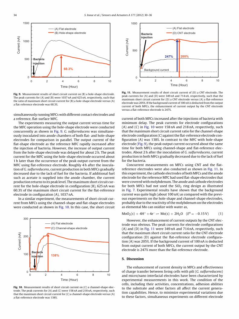
Fig. 11. Measurement results of short circuit current of (D) a CNT electrode. Thepeak currents for (A) and (D) were 349 nA and 714 nA, respectively, such that themaximum short circuit current for (D) a CNT electrode versus (A) a flat-reference
he peak currents for (A) and (B) were 1037 nA and 625 nA, respectively, such thathe ratio of maximum short circuit current for (B) a hole-shape electrode versus (A)
flat-reference electrode was 60.3%.
imultaneously running MFCs with different contact electrodes and reference, flat-surface MFC.
The experiments measuring the output current versus time forhe MFC operation using the hole-shape electrode were conductedoncurrently as shown in Fig. 9. G. sulfurreducens was simultane-usly inoculated into anode chambers of both flat- and hole-shapelectrodes for comparison in parallel. The output current of theat-shape electrode as the reference MFC rapidly increased afterhe injection of bacteria. However, the increase of output currentrom the hole-shape electrode was delayed for about 2 h. The peakurrent for the MFC using the hole-shape electrode occurred about
h later than the occurrence of the peak output current from theFC using flat-reference electrode. Roughly 4 h after the inocula-
ion of G. sulfurreducens, current production in both MFCs graduallyecreased due to the lack of fuel for the bacteria. If additional fueluch as acetate is supplied into the anode chamber, the currentroduction returns to its peak level. The maximum short circuit cur-ent for the hole-shape electrode in configuration (B), 625 nA was0.3% of the maximum short circuit current for the flat-referencelectrode in configuration (A), 1037 nA.
In a similar experiment, the measurements of short circuit cur-ent from MFCs using the channel-shape and flat-shape electrodesere conducted as shown in Fig. 10. In this case, the short circuit
0
100
200
300
1086420
(A) Flat electrode
(C) Channel-shape electrode
Time (Hour)
Cur
rent
(nA
)
138%Bacteriainjection
ig. 10. Measurement results of short circuit current on (C) a channel-shape elec-rode. The peak currents for (A) and (C) were 158 nA and 218 nA, respectively, suchhat the maximum short circuit current for (C) a channel-shape electrode versus (A)
flat-reference electrode was 138%.
electrode was 205%. If the background current of 100 nA is deducted from the outputcurrent of both MFCs, the enhancement of current output by the CNT electrodeversus a flat-reference electrode is 247%.
current of both MFCs increased after the injections of bacteria withminimum delay. The peak currents for electrode configurations(A) and (C) in Fig. 10 were 158 nA and 218 nA, respectively, suchthat the maximum short circuit current ratio for the channel-shapeelectrode configuration (C) against the flat-reference electrode con-figuration (A) was 138%. In contrast to the MFC with hole-shapeelectrode (Fig. 9), the peak output current occurred about the sametime for both MFCs using channel-shape and flat-reference elec-trodes. About 2 h after the inoculation of G. sulfurreducens, currentproduction in both MFCs gradually decreased due to the lack of fuelfor the bacteria.
Concurrent measurements on MFCs using CNT and the flat-reference electrodes were also conducted as shown in Fig. 11. Inthis experiment, the cathode electrodes of both MFCs and the anodeelectrode for the reference MFC had used flat-shape electrodes thatwere covered with molybdenum. The anode and cathode electrodesfor both MFCs had not used the SiO2 ring design as illustratedin Fig. 7. Experimental results have shown that the backgroundcurrent was quite high (about 100 nA) as compared with the previ-ous experiments on the hole-shape and channel-shape electrodes,probably due to the reactivity of the molybdenum on the electrodesas elemental Mo can oxidize with water as,
MoO2(s) + 4H+ + 4e− � Mo(s) + 2H2O (Eo = −0.15 V) (1)
However, the enhancement of current outputs by the CNT elec-trode was obvious. The peak currents for electrode configurations(A) and (D) in Fig. 11 were 349 nA and 714 nA, respectively, suchthat the maximum short circuit current ratio for the CNT electrodeconfiguration (D) against the flat-reference electrode configura-tion (A) was 205%. If the background current of 100 nA is deductedfrom output current of both MFCs, the current output by the CNTelectrode is 247% more than the flat-reference electrode.
5. Discussion
The enhancement of current density in MFCs and effectivenessof charge transfer between living cells with pili (G. sulfurreducens)and micro/nano interfacial electrodes have been characterized byexperimental measurements in this work. The condition of the
cells, including their activities, concentrations, adhesion abilitiesto the substrate and other factors all affect the current genera-tion capabilities. Hence, to minimize experimental variations dueto these factors, simultaneous experiments on different electrode
S. Inoue et al. / Sensors and Actuators A 177 (2012) 30– 36 35
Proportion
(D) CNTnot deducted
backgr ound current
(C) Channel
(B) Hole
(A) Flat electrode(Reference)
32100
1
2
3
Normalized su rface are a
Nor
mal
ized
max
imum
shor
t circ
uit c
urre
nt
(D) CNTdeduct ed
backg round curre nt
Fig. 12. Experimental results of MFCs showing maximum output current vs. cell-to-electrode contact area of various MFCs. The red circle for (D) CNT indicates thenormalized maximum short circuit current without deducting the background cur-rent and the blue square for (D) CNT indicates the normalized maximum short circuitcurrent after deducting the background current of 100 nA. The linear relationshipsupports the hypothesis that only bacteria attached to the electrode surface candpt
cbocttrofiesesatsmcmcctCeco
octcal[ptbotfw
Fig. 13. Schematic of bacteria fully filled into a CNT forest with the dimension
onate electrons and this is likely the key mechanism of charge transfer. (For inter-retation of the references to colour in this figure legend, the reader is referred tohe web version of this article.)
onfigurations were conducted. Nevertheless, the peak currentseing generated by the flat-electrode configuration (A) differed inur experiments likely due to the usage of cells under differentulturing periods. In spite of these differences, current ratios fromhe simultaneous experiments of different electrode configura-ions provide valuable insight. Fig. 12 summarizes the experimentalesults of maximum short circuit currents (normalized to currentutput of flat-reference electrode) from various MFCs with dif-erent electrode structures versus the calculated surface areas ofndividual corresponding electrodes (normalized to flat-referencelectrode). The spot (A) reflects the result of simultaneous mea-urement of two identical reference MFCs which have exactly samelectrode surface area, and the value is close to 1 as expected. Themall discrepancy from 1 indicates the possible experimental vari-bility in concurrent measurements. The rest of the data followshe expected linear relationship between the current and effectiveurface area. The red circle for (D) CNT indicates the normalizedaximum short circuit current without deducting the background
urrent and the blue square for (D) CNT indicates the normalizedaximum short circuit current after deducting the background
urrent of 100 nA in the same way as Fig. 11. Although the red cir-le for (D) CNT is slightly smaller than the expected value fromhe effective surface area of the electrode, the blue square for (D)NT nearly follows the linear relationship between the current andffective surface area. This result suggests that the backgroundurrent should be deducted for evaluating the enhanced currentutputs.
As no added electron mediator was added in the setup, the resultf the linear relationship supports the hypothesis that the mainharge transfer mechanism is from bacteria attaching to the elec-rode surface to donate electrons. The CNT electrodes improved theurrent density about 200% as the effective surface area increasedbout 200%. It has been reported, however, that CNTs have a cellu-ar toxicity that could lead to proliferation inhibition and cell death26,27]. In this work, the toxicity of CNTs has not been observedrobably because the run time was short (less than 10 h). For long-erm applications, the modifications of electrodes with CNTs maye necessary to reduce the cellular toxicity by coating with some
ther materials, such as polyaniline [8]. The CNT forests used inhis work were of high density, hence, via size exclusion, G. sul-urreducens could have penetrated in-between CNT walls but notithin CNT forests. One possible future direction is to synthesize
of 10 mm × 10 mm × 1 mm. The maximum output power is estimated as high as12 mW from the measured power density of 3.6 �W/cm2 (the diameter of bacteriais 0.3 �m).
CNT forests with larger gaps to accommodate a higher density ofbacteria. For example, if bacteria are fully filled into CNT forestswith the dimension of 10 mm × 10 mm × 1 mm as shown in Fig. 13,the maximum output power is roughly estimated as high as 12 mWfrom the measured power density of 3.6 �W/cm2 in Fig. 8 (thediameter of bacteria is 0.3 �m). This prospective power density isenough to for powering not only most autonomous microsystems,but also small portable electronics.
6. Conclusions
More than a 200% current density enhancement in miniatur-ized microbial fuel cells has been successfully demonstrated byoptimizing the contact electrode structure using micro and nanofeatures. The data demonstrates a linear relationship between thecurrent production and effective surface area of electrodes. Thisresult supports the hypothesis that the charge transfer mechanismis based on direct attachment of bacteria to the electrode surfacefor electron transport. We estimate that the volumetric power den-sity of MFCs using CNT forests with larger gaps could be as high as12 mW/100 mm3.
Acknowledgements
This work was performed at the University of California, Berke-ley during 2009–2010 when Shogo Inoue worked for FUJITSULABORATORIES LTD. The project was partially supported by theSustainable Products and Solutions Program at the University ofCalifornia, Berkeley and the University of California President’sPostdoctoral Fellowship (Cullen R. Buie).
References
[1] D.R. Bond, D.E. Holmes, L.M. Tender, D.R. Lovley, Electrode-reducing microor-ganisms that harvest energy from marine sediments, Science 295 (2002)483–485.
[2] S. Choi, H. Lee, Y. Yang, P. Parameswaran, C.I. Torres, B.E. Rittmann, J. Chae, A�L-scale micromachined microbial fuel cell having high power density, Lab.Chip 11 (2011) 1110–1117.
[3] Y. Chen, Y. Zhao, K. Qiu, J. Chu, R. Lu, M. Sun, X. Liu, G. Sheng, H. Yu, J. Chen, W. Li,G. Liu, Y. Tian, Y. Xiong, An Innovative miniature microbial fuel cell fabricatedusing photolithography, Biosens. Bioelectron. 26 (2011) 2841–2846.
[4] M. Chiao, K.B. Lam, L. Lin, Micromachined microbial fuel cells, in: Proc. IEEEMEMS Conference, Kyoto, 2003, pp. 383–386.
[5] M. Chiao, K.B. Lam, L. Lin, Micromachined microbial and photosynthetic fuelcells, J. Micromech. Microeng. 16 (2006) 2547–2553.
[6] E. Parra, L. Lin, Microbial fuel cell based on electrode-exoelectrogenic bacterialinterface, in: Proc. IEEE MEMS Conference, Sorrento, 2009, pp. 31–34.
[7] K.B. Lam, E. Johnson, L. Lin, A MEMS photosynthetic electrochemical cellpowered by sub-cellular plant photosystems, IEEE/ASME JMEMS 15 (2006)1243–1250.
[8] Y. Qiao, C.M. Li, S. Bao, Q. Bao, Carbon nanotube/polyaniline composite as anodematerial for microbial fuel cells, J. Power Sources 170 (2007) 79–84.

3 Actu
[
[
[
[
[
[
[
[
[
[
[[
[
[
[
[
6 S. Inoue et al. / Sensors and
[9] T. Sharma, A.L.M. Reddy, T.S. Chandra, S. Ramaprabhu, Development of carbonnanotubes and nanofluids based microbial fuel cell, Int. J. Hydrogen Energy 33(2008) 6749–6754.
10] J.L. Lamp, J.S. Guest, S. Naha, K.A. Radavich, N.G. Love, M.W. Ellis, I.K. Puri, Flamesynthesis of carbon nanostructures on stainless steel anodes for use in microbialfuel cells, J. Power Sources 196 (14) (2011) 5829–5834.
11] P. Liang, H. Wang, X. Xia, X. Huang, Y. Mo, X. Cao, M. Fan, Carbon nanotube pow-ders as electrode modifier to enhance the activity of anodic biofilm in microbialfuel cells, Biosens. Bioelectron. 26 (2011) 3000–3004.
12] S. Oh, B. Min, B.E. Logan, Cathode performance as a factor in electricity gener-ation in microbial fuel cells, Environ. Sci. Technol. 38 (2004) 4900–4904.
13] S. Oh, B.E. Logan, Proton exchange membrane and electrode surface areas asfactors that affect power generation in microbial fuel cells, Appl. Microbiol.Biotechnol. 70 (2006) 162–169.
14] K.B. Lam, E.F. Irwin, K.E. Healy, L. Lin, Bioelectroanalytic self-assembled thy-lakoids for micro power and sensing applications, Sens. Actuators B: Chem.117 (2006) 480–487.
15] S. Inoue, E.A. Parra, A. Higa, L. Lin, Cell-to-electrode contact structures for powerdensity enhancements in microbial fuel cells, in: Proc. IEEE MEMS Conference,Cancun, 2011, pp. 1297–1300.
16] G. Reguera, K.D. McCarthy, T. Mehta, J.S. Nicoll, M.T. Tuominen, D.R. Lovley,
Extracellular electron transfer via microbial nanowires, Nature 435 (2005)1098–1101.17] G. Reguera, K.P. Nevin, J.S. Nicoll, S.F. Covalla, T.L. Woodard, D.R. Lovley, Biofilmand nanowire production leads to increased current in Geobacter sulfurreducensfuel cells, Appl. Environ. Microbiol. 72 (2006) 7345–7348.
[
[
ators A 177 (2012) 30– 36
18] K.P. Nevin, B. Kim, R.H. Glaven, J.P. Johnson, T.L. Woodard, B.A. Methe, R.J. DiDo-nato, S.F. Covalla, A.E. Franks, A. Liu, D.R. Lovley, Anode biofilm transcriptomicsreveals outer surface components essential for high density current productionin Geobacter sulfurreducens fuel cells, PLoS One 4 (2009) 1–11.
19] Y.Q. Jiang, Q. Zhou, L. Lin, Planar MEMS supercapacitor using carbon nanotubeforests, in: Proc. IEEE MEMS Conference, Sorrento, 2009, pp. 587–590.
20] DuPontTM Nafion® PFSA membrane NR211(1 mil).21] Y.Q. Jiang, P. Wang, J. Zhang, W. Li, L. Lin, 3D supercapacitor using nickel electro-
plated vertical aligned carbon nanotube array electrode, in: Proc. IEEE MEMSConference, Hong Kong, 2010, pp. 1171–1174.
22] S. Choi, J. Chae, A series array of microliter-sized microbial fuel cell, in: Proc.IEEE MEMS Conference, Cancun, 2011, pp. 1289–1292.
23] D.R. Bond, D.R. Lovley, Electricity production by Geobacter sulfurreducensattached to electrodes, Appl. Environ. Microbiol. 69 (2003) 1548–1555.
24] K.P. Nevin, H. Richter, S.F. Covalla, J.P. Johnson, T.L. Woodard, A.L. Orloff, H. Jia,M. Zhang, D.R. Lovley, Power output and columbic efficiencies from biofilms ofGeobacter sulfurreducens comparable to mixed community microbial fuel cells,Environ. Microbiol. 10 (2008) 2505–2514.
25] H. Yi, K.P. Nevin, B. Kim, A.E. Franks, A. Klimes, L.M. Tender, D.R. Lovley, Selec-tion of a variant of Geobacter sulfurreducens with enhanced capacity for currentproduction in microbial fuel cells, Biosens. Bioelectron. 24 (2009) 3498–3503.
26] E. Flahaut, M.C. Durrieu, M. Remy-Zolghadri, R. Bareille, C.H. Baquey, Study ofthe cytotoxicity of CCVD carbon nanotubes, J. Mater. Sci. 41 (2006) 2411–2416.
27] A. Magrez, S. Kasas, V. Salicio, N. Pasquier, J.W. Seo, M. Celio, S. Catsicas, B.Schwaller, L. Forro, Cellular toxicity of carbon-based nanomaterials, Nano Lett.6 (2006) 1121–1125.