chassishyosung.co.nz/media/wysiwyg/dealer-login/service-man… · · 2012-12-11chassis front...
TRANSCRIPT
CHASSIS
FRONT WHEEL 6- 1
FRONT BRAKE 6- 7
FRONT FORK 6-14
STEERING 6-18
REAR WHEEL AND REAR BRAKE 6-22
CONTENTS
6

6-1 CHASSIS
①
Do not operate the front brake lever while dis-mounting the caliper.
CAUTION
REMOVAL AND DISASSEMBLY● Remove the front brake caliper by removing the
mounting bolts ①.
FRONT WHEEL

CHASSIS 6-2
● Remove the front axle nut.● Support the motocycle by jack or wooden block.● Remove the front wheel and speedometer gear box
by removing the front axle shaft.
● Remove the disc plate ① by removing the bolts.
● Remove the spacer ②.
①
②
③
Oil seal remover : 09913-50121
● Remove the oil seal ③ with the special tool.

6-3 CHASSIS
Wheel bearing remover : 09941-50111
Drive out the both bearing with the special tool in the fol-lowing procedures.● Insert the adapter into the bearing.● After inserting the wedge bar from the opposit side,
lock the wedge bar in the slit of the adapter.● Drive out the bearing by knocking the wedge bar.
The removed dust seal and bearing should bereplaced with new ones.
CAUTION
Wheel rim runout(Axle and Radial)
Service limit 3.0 mm
INSPECTIONWHEEL RIMMake sure that the wheel rim runout does not exceedthe service limit when checked as shown.An excessive runout is usually due to worn or loosewheel bearings and can be reduced by replacing thebearings. If bearing replacement fails to reduce therunout, replace the wheel.
TIREInspect the tires for wear and damage, and check thetire tread depth as shown. Replace a badly worn or dam-aged tire. A tire with its tread worn down to the limit(interms of tread depth)must be replaced.
Dial gauge(1/100 mm) : 09900-20606Magnetic stand : 09900-20701

CHASSIS 6-4
Right side Left side
Bearing(L)
Bearing(R) Spacer
Clearance Bearing(L)
S hS hA lv niaaell
3
I nduI ndu
M ulti-M ulti-purpurstrialstrial
posepose G reaseG rease
Tire depthservice limit
Front 1.6 mm
1.6 mmRear
TIRE PRESSURECold inflation
Normal riding
Solo riding Dual riding
kg/㎠
1.25
2.00
kPa
123
196
kg/㎠
1.75
2.25
kPa
172
221
Front
Rear
Check the tire pressure, and examine the value for evi-dence of air leakage.
REASSEMBLY AND REMOUNTINGReassemble and remount the front wheel in the reverseorder diassembly and removal, and also carry out thefollowing steps.
WHEEL BEARING● Apply SUPER GREASE“A”to the bearings before
installing.
● Install the wheel bearings by using the special tool.Super Grease“A”
Bearing installer set : 09924-84521
First install the wheel bearing for left side.
CAUTION

6-5 CHASSIS
①
②
�
�
Front brake disc bolt : 18 ~ 28 N∙m(1.8 ~ 2.8 kg∙m)
Oil seal installer : 09923-55131
OIL SEAL● Install the oil seal ① with the special tool.
● Install the spacer ②.
DISC PLATE● Install the disc plate and tighten them to the specified
torque.
SPEEDOMETER GEAR BOX● When installing the speedometer gear box, align the
two drive pawls � with the two recesses � of thewheel hub.

CHASSIS 6-6
�
�
After touching the speedometer gear box � tothe stopper �, tighten the axle shaft.
CAUTION
FRONT WHEEL● Tighten the front axle nut to the specified torque.
● Tighten the caliper mounting bolts to the specifiedtorque.
Front axle nut : 33 ~ 52 N∙m(3.3 ~ 5.2 kg∙m)
Front brake caliper mounting bolt : 18 ~ 28 N∙m(1.8 ~ 2.8 kg∙m)
6-7 CHASSIS
①
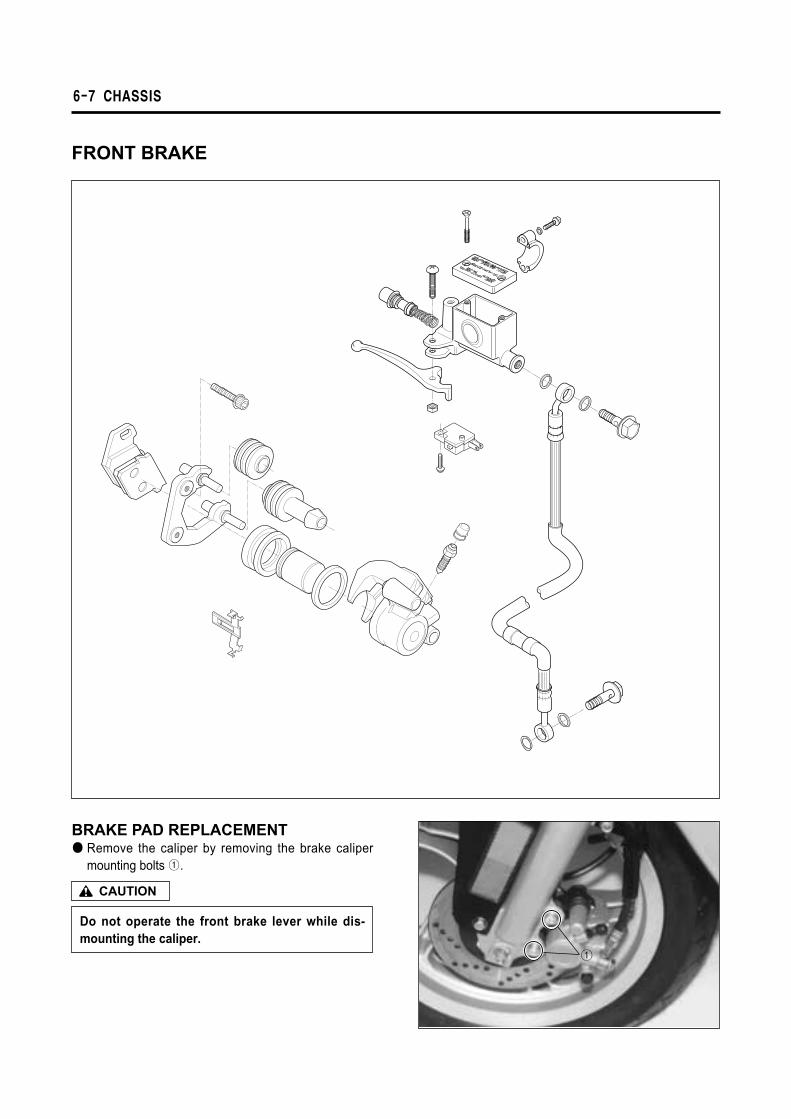
FRONT BRAKE
Do not operate the front brake lever while dis-mounting the caliper.
CAUTION
BRAKE PAD REPLACEMENT● Remove the caliper by removing the brake caliper
mounting bolts ①.

CHASSIS 6-8
①
③
②
④
⑤
Replace the brake pads as a set, otherwise brak-ing performance will be adversely affected.
CAUTION
● Reassemble it after remove the brake pads ①.
Never re-use the brake fluid left over from the lastservicing and stored long periods.
CAUTION
CALIPER REMOVAL AND DISASSEMBLY● Remove the brake hose ② and catch the brake fluid
in a suitable receptacle.● Remove the caliper mounting bolt ③.
● Remove the caliper.● Remove the brake pads.● Remove the pad holder ④.
● Remove the spring ⑤.
6-9 CHASSIS
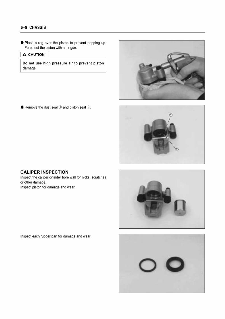
①
②
Do not use high pressure air to prevent pistondamage.
CAUTION
● Place a rag over the piston to prevent popping up.Force out the piston with a air gun.
● Remove the dust seal ① and piston seal ②.
CALIPER INSPECTIONInspect the caliper cylinder bore wall for nicks, scratchesor other damage.Inspect piston for damage and wear.
Inspect each rubber part for damage and wear.

CHASSIS 6-10
{{
①
②
CALIPER REASSEMBLYReassemble and remount the caliper in the reverseorder of removal and disassembly, and also carry out thefollowing steps.
Wash the caliper components with fresh brakefluid before reassembly. Never use cleaning sol-vent or gasoline to wash them. Apply brake fluidto the caliper bore and piston to be inserted intothe bore.
CAUTION
Silicone Grease
● Apply SILICONE GREASE to the caliper holder.
DISC PLATE REMOVAL AND DISASSEMBLY● Remove the front wheel.(Refer to page 6-2)● Remove the disc plate.(Refer to page 6-2)● Install the disc plate.(Refer to page 6-4)
SPECIFIED TORQUE
Item
①
②
N∙m
18 ~ 28
20 ~ 25
kg∙m
1.8 ~ 2.8
2.0 ~ 2.5
Bleed the air from brake fluid circuit afterreassembling caliper.(Refer to page 2-9)
WARNING
Disc thickness Service limit 3.5 mm
Micrometer(0 ~ 25mm) : 09900-20201
DISC PLATE INSPECTION● Check the disc for wear with a micrometer. Its thick-
ness can be checked with disc and wheel in place.Replace the disc if the thickness exceeds the servicelimit.

6-11 CHASSIS
● With the disc mounted on the wheel, check the discfor face runout with a dial gauge as shown. Replacethe disc if the runout exceeds the service limit.
MASTER CYLINDER REMOVAL AND DISASSEMBLY● Remove the handlebar cover.● Disconnect the front brake lamp switch lead wires.
Dial gauge(1/100 mm) : 09900-20606Magnetic stand : 09900-20701
Disc runout Service limit 0.3 mm
Completely wipe off any brake fluid adhering toany part of motorcycle. The fluid reacts chemical-ly with paint, plastics, rubber materials, etc.
CAUTION
● Place a cloth underneath the union bolt on the mastercylinder to catch spilled drops of brake fluid. Unscrewthe union bolt and disconnect the brake hose/mastercylinder joint.
● Remove the master cylinder.

CHASSIS 6-12
①
②
③
④
⑥
⑦ ⑤
}● Remove the brake lever ① and brake switch ②.
● Remove the dust boot ③.
● Remove the circlip ④ with the special tool.
● Remove the piston/primary cup with return spring ⑤.● Remove the reservoir cap ⑥ and diaphragm ⑦.● Drain brake fluid.
Snapring pliers : 09900-06108

6-13 CHASSIS
Boot
Circlip
Second cap
PistonPrimary cap
spring
Master cylinder
Upside
Handlebar
Clearance
MASTER CYLINDER INSPECTIONInspect the master cylinder bore for any scratches orother damage.Inspect the piston surface for scratches or other dam-age.Inspect the primary cup and dust boot for wear or dam-age.
MASTER CYLINDER REASSEMBLY ANDREMOUNTINGReassemble and remount the master cylinder in thereverse order of removal and disassembly, and alsocarry out the following steps.
Wash the master cylinder components with freshbrake fluid before reassembly. Never use clean-ing solvent or gasoline to wash them.Apply brake fluid to the cylinder bore and all theinternals to be inserted into the bore.
CAUTION
Bleed air after remounting the master cylinder.
CAUTION
● Reassemble and remount the master cylinder.(Referto page 6-11)
● When remounting the master cylinder on the handle-bar, first tighten the clamp bolt for upside.

CHASSIS 6-14
FRONT FORK
Do not operate the front brake lever while dis-mounting the caliper.
CAUTION
REMOVAL AND DISASSEMBLY● Remove the front leg shield.● Remove the front brake caliper by removing the
mounting bolts.

6-15 CHASSIS
②
①
③
● Remove the front axle nut.● Support the motorcycle by jack or wooden block.● Remove the front wheel by removing the front axle
shaft.
● Loosen the front fork bolt, then draw out the forkspring.
● Loosen the front fork lower clamp bolts.
● Invert the fork and stroke it several times to removethe oil.
● Hold the fork inverted for a few minutes.
● Remove the socket bolt ① with the hexagon wrench.● Seperate the fork pipe ② and pipe seat ③.

CHASSIS 6-16
①
②
● Remove the dust boot ① and stopper ring ②.
The oil seal removed should be replaced with anew oil seal.
CAUTION
Oil seal remover : 09913-50121
INSPECTION● Inspect pipe seat for wear and damage.
● Inspect fork pipe and bottom case sliding surfaces forany scuffing or flaws.
● Remove the oil seal by using the special tool.

6-17 CHASSIS
290.9
Up side
}}
Fork spring free length Standard 290.9 mm
FORK SPRING● Measure the fork spring free length.
REASSEMBLY AND REMOUNTINGReassemble and remount the fork in the reverse order ofremoval and disassembly, and also carry out the follow-ing steps.
FRONT FORK BOLT● Apply BOND “1215”and THREAD LOCK “1324”to
the fork bolt and tighten the bolt with specified torque.
CUSHION SPRING● When installing the front fork spring, the close end
should position upside.
Bond “1215”
Thread Lock “1324”
Front fork bolt : 35 ~ 55 Nㆍm(3.5 ~ 5.5 kgㆍm)
TELLUS # 37
50 cc(One side)
Fork oil type
Capacity
FORK OIL● For the fork oil, be sure to use a front fork oil whose
viscosity rating meets specification below.

CHASSIS 6-18
①②
③
⑦
⑥
⑤
④
STEERING
REMOVAL AND DISASSEMBLY● Remove the handlebar cover.● Remove the handlebar by removing the clamp bolt ①
and set bolt ②.
● Loosen the steering stem lock nut ③ with the specialtool.
● Remove the front fork assembly by removing the lockwasher ④, steering outer upper race ⑤ and dust seal⑥.
● Remove the steering outer lower race ⑦ with a chisel.
Clamp wrench : 09940-10122
Do not drop the steering stem steel balls.
CAUTION
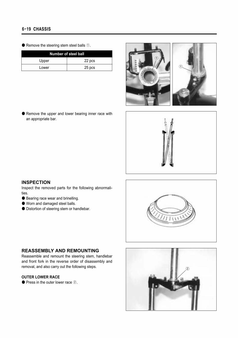
6-19 CHASSIS
①
①
②
● Remove the upper and lower bearing inner race withan appropriate bar.
INSPECTIONInspect the removed parts for the following abnormali-ties.● Bearing race wear and brinelling.● Worn and damaged steel balls.● Distortion of steering stem or handlebar.
REASSEMBLY AND REMOUNTINGReassemble and remount the steering stem, handlebarand front fork in the reverse order of disassembly andremoval, and also carry out the following steps.
OUTER LOWER RACE● Press in the outer lower race ②.
Number of steel ball
Upper
Lower
22 pcs
25 pcs
● Remove the steering stem steel balls ①.

CHASSIS 6-20
①
②
INNER RACE● Press in the upper and lower inner races with the spe-
cial tool.
STEEL BALL● Apply SUPER GREASE “A”when installing the
upper and lower steel balls.
Steering race installer : 09941-34513
Number of steel ball
Upper
Lower
22 pcs
25 pcs
Make sure that the steering turns smoothly andeasily, left to right.
CAUTION
STEERING OUTER UPPER RACE NUT● Tighten the steering outer upper race ① until resis-
tance is felt, then loosen it 1/8 ~ 1/4 turn.
Clamp wrench : 09940-10122
Steering stem lock nut : 60 ~ 100 Nㆍm(6.0 ~ 10.0 kgㆍm)
● Tighten the steering stem lock nut ② with the specialtool.
Super Grease “A”

6-21 CHASSIS
②
①
Handlebar set bolt : 22 ~ 28 Nㆍm(2.2 ~ 2.8 kgㆍm)Handlebar clamp bolt : 48 ~ 52 Nㆍm(4.8 ~ 5.2 kgㆍm)
● Install the handlebar and tighten the set bolt ① andclamp bolt ② to the specified torque.
● After install the front fork and steering stem, inspectthe following items.
∙Lift the front fork.∙Inspect play of the front fork as that grasp lower of
the front fork and shake it by the front and rear.∙By the handle turning the right or left, inspect
whether turning smoothly.∙Adjust the outer upper race, if the steering is comed
heavy and tight.● Bleed air of the front brake.(Refer to page 2-9)

CHASSIS 6-22
①
REAR WHEEL AND REAR BRAKE
REMOVAL AND DISASSEMBLY● Place the motorcycle on level ground.● Remove the muffler.(Refer to page 3-4)● Remove the rear wheel by removing the axle nut ①.

6-23 CHASSIS
Slit
Punch mark
�Front
�Front
Brake shoe lining for thickness Service limit 96 mm
BRAKE SHOEUsing a vernier calipers, measure the brake shoe out-side diameter at the place as shown in the photo. If themeasurement is less than the limit, replace the brakeshoe.
REASSEMBLY AND REMOUNTINGReassemble and remount the rear wheel and brake inthe reverse order of removal, and diassembly.
BRAKE CAM LEVER● When installing the brake cam lever, align the
punched mark of camshaft with the slit on cam lever.
REAR BRAKE SHOE● Apply SUPER GREASE “A”to the camshaft and pin
before installing the brake shoes.
WHEELRefer to page 6-3.TIRERefer to page 6-4.
Rear brake drum I.D Service limit 100.7 mm
INSPECTIONREAR BRAKE DRUMMeasure the brake drum I.D. to determine the extent ofwear and, if the limit is exceeded by the wear noted,replace the drum. The value of this limit is indicatedinside the drum.
Replace the brake shoe with a set, otherwisebraking performance will be adversely affected.
CAUTION
Brake cam lever bolt : 6 ~ 9 Nㆍm(0.6 ~ 0.9 kgㆍm)
Super Grease “A”
Be careful not to apply too much grease to thecamshaft and pin. If grease gets on the lining,brake effectiveness will be lost.
CAUTION

CHASSIS 6-24
REAR AXLE NUT● Tighten the rear axle nut to the specified torque.
Rear axle nut : 60 ~ 90 Nㆍm(6.0 ~ 9.0 kgㆍm)