2012 11-13 = sfc roundtable interference limits
TRANSCRIPT

Interference Limits PolicyAn Introduction
Silicon Flatirons Roundtable on Receivers, Interference & Regulatory Options
13 November 2012
Pierre de VriesSilicon Flatirons Center, UC Boulder
1
The Problem
2
Improve receiver interference tolerance
… without mandating receiver performance

The Problem (2)
• When can a receiver stop a neighbor transmitting at authorized levels inside that neighbor’s band?
3
Receiver Transmitter
Received signal strength
Frequency
□ Always□ Sometimes□ Never□ Don’t Know
Harmful Interference?
✓

Interference Limits: a Definition
• Explicit, up-front statement of the interference that a system needs to tolerate before it can bring a harmful interference claim
– A harm claim threshold NOT an attempt to characterize actual the interference environment
– It doesn’t attach to a receiver as such: a system = transmitter + receiver
• Every allocation’s interference limit will be a customized combination of signal strength, probability levels, etc.
field strength
frequencyBand to be allocated
px , pt
4
Percentage of locations and times where field strength cannot be exceeded
Field strength (all polarizations, any modulation, at specified height) above which receiving system can claim harmful interference
No protection beyond this point, i.e. receiving system has to tolerate any interfering signals

px , pt
Interference level chosen to reflect planned, not
current, conditions
Choosing Receiver Interference Limits
5
field strength
frequency
px , pt
Probability of resulting signal strength above
limit
Currentinterference
level
Band to be allocated
Receiver interference limit with probability of not being exceeded; chosen to accommodate current
and planned conditions
px , pt

Connecting interference limits to receiver performance
6
Interference Limit
rules
Specification:
Receiver performanceSpecification:
Transmitter performance
Specification:
Interference Protection
Ratios
Specification:
Transmitter deployment:
power, height, spacing, …
Design requirement:
RF interference to be
tolerated
Design input: Estimate of
expected RF interference
environment
Design requirement:
Desired signal
characteristics
Design requirement:
Quality of service
Design requirement:
Business case
Design requirement:
Cost constraints
Regulation:
Transmitters, receivers
Industry standards,
best practicesSystem Design
Process

Implementation
• Start with band boundaries where problems can be foreseen
• Use multi-stakeholder process to seek consensus, then move to NOI, rule-making as necessary
• FCC can ratchet up harm claim thresholds to drive or reflect improvement in system interference tolerance where market forces are insufficient
• Interference limits may not be sufficient in some cases, e.g. decoupled receivers, unlicensed devices, safety of life, sharing with government 7

Examples
A. Protect incumbent neighbor: cellular downlink
B. Protect incumbent receiver: TV
1. Single value (at contour)
2. Thresholds vary across service area
8

A. Protect incumbent neighbor: Cellular downlink
• For new allocation, to allow incumbent or anticipated cellular neighbor next door
• Choose harm claim threshold to allow operation of cellular downlink
– i.e. new allocation won’t be able to claim harmful interference given envisaged cellular operation
• Use modeled resulting field strengths for generic base station deployment as basis for thresholds
– In-block cellular field strength ≡ floor for adjacent-block harm claim threshold, and vice versa
9

Ofcom/Transfinite downlink simulation
10

Simulation parameters
• Ofcom commissioned Transfinite (2008) to compute the signal strengths of a variety of services that use the UHF band
• For an IMT-2000 downlink
– Frequency: 826 MHz
– Bandwidth: 3.84 MHz within 5 MHz (standard WCDMA channel bandwidth)
– Transmitter height 30 m; transmitter separation distance 1.86 km
– Total EIRP all users: 22.7 dBW
– Power attenuation at frequency offset of 5 MHz: 46.2 dB
– Baseline propagation model: ITU-R Rec. P.1546 version 1546-2, configured for 50% of time and a location variability standard deviation of 5.5 dB
– Simulation file: seven base stations in hexagonal cellular structure, 479 test point in central cell, aggregate pfd determined at height of 10 m
11

Example: Determining px for base stations
Source: Ofcom/Transfinite 2008. Modeled PFD of IMT-2000 base station population, 10 m altitude
PFD at 10 m doesn’t exceed -42 dB(W/m2) per MHz
(+104 dB(μV/m) per MHz)at more than 5% of
locations
5%
-42
PFD at 10 m doesn’t exceed -60 dB(W/m2) per MHz
at more than 50% of locations
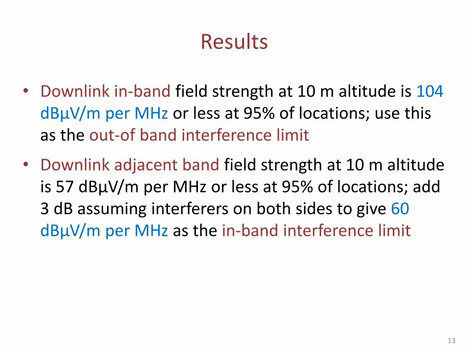
Results
• Downlink in-band field strength at 10 m altitude is 104 dBμV/m per MHz or less at 95% of locations; use this as the out-of band interference limit
• Downlink adjacent band field strength at 10 m altitude is 57 dBμV/m per MHz or less at 95% of locations; add 3 dB assuming interferers on both sides to give 60 dBμV/m per MHz as the in-band interference limit
13

Cellular-inspired Interference Limitfield strengthdBμV/m per MHz
FrequencyMHz
NTE at >5% of locations, >50% of time; observed at 10 meter altitude
60
104
§15.209 limit: 54 dBμV/m per MHz at 3 meters
14
Cellular DL in this blockInterference limit for operator in this block

B. Protect incumbent: TV receivers
• Approach
– Assume desired signal strength D and adjacent channel protection ratio D/U
– Calculate max undesired signal strength U from requirementU ≤ D – D/U
• Options
1. Single harm claim threshold using Part 73 D/U ratios and desired signal at service contour
2. Location-dependent threshold: Use interference thresholds and measurement protocol defined in 47 CFR 73.616 (e)(1) and OET 69 to define interference limits that vary with grid cell across service area
15

Option 1. Part 73, at contour only
• Single harm claim threshold using Part 73 D/U ratios and desired signal at service contour
– Part 73: field strength at the NLSC is 41 - 20 log[615/(channel mid-freq)] dBu/6MHz.
• To simplify, assume we’re looking at 615 MHz, so D = 41 dBu/6MHz.
– Part 37.616: the {-1, 0, +1} channel D/Us are {-28, +23, -26} dB
• So harm claim thresholds U = D – D/U = {69, 18, 67} dBu/6MHz:
– “An end user cannot claim harmful interference unless their receiver can operate satisfactorily for U = {69, 18, 67} dBu/6MHz given D = 41 dBu/6MHz”
16

Option 1: Notes
• Doesn’t meet interference limit paradigm of harm claim threshold defined probabilistically across license area
– Provides no guidance to the regulator or adjacent licensees about the maximum allowed signal that could be delivered by a neighbor when D > 41, i.e. inside the contour, closer to the transmitter.
• FCC could use branding program to label receivers that meet this criterion
• Who’s entitled to protection: service (broadcaster) or receiver (consumer)?
17

2. Part 73 applied across service area
• A TV licensee may not may not claim harmful interference unless the interfering signal exceeds the thresholds set in Part 73.616
– Calculate desired field strength D using Longley-Rice in each 2x2 km grid cell, following OET Bulletin 69
– Use D/U ratios for co- and first-adjacent channels in Part 73.616 (e)(1) to calculate D for each cell
– Apply F(50,10) undesired signal test
18

Part 73.616 (e)(1)
“. . . The threshold levels at which interference is considered to occur are:
(i) For co-channel stations, the D/U ratio is 15 dB.
This value is only valid at locations where the signal-to-noise ratio is 28 dB or greater.
At the edge of the noise-limited service area, where the signal-to-noise (S/N) ratio is 16 dB, this value is 23 dB.
At locations where the S/N ratio is greater than 16 dB but less than 28 dB, D/U values are computed from the following formula:
D/U = 15 10log10*1.0/(1.0−10−x/10)+ , where x = S/N-15.19 (minimum signal to noise ratio)
(ii) For interference from a lower first-adjacent channel, the D/U ratio is −28 dB.
(iii) For interference from an upper first-adjacent channel, the D/U ratio is −26 dB.”
19

Part 73-inspired harm claim thresholds
• Within each reference cell with calculated median desired signal strength D, a receiver may not claim harmful interference unless the interfering signal exceeds {D+28, D+26} dBu/(6 MHz) on the {-1, +1} channels at more than 50% of locations, more than 10% of the time.
• Within each reference cell with a calculated median desired signal strength D, a receiver may not claim harmful interference unless the interfering signal exceeds the following values in dBu/(6 MHz)
D = 41.6 - Ka: 18.6 - Ka
41.6 - Ka >= D < 53.6 - Ka: D - Ka - 15+10log10[1.0/(1.0 -10^{-x/10})], where x = D + Ka - 40.8, Ka = dipole factor
D >= 53.6 - Ka: 38.6 - Ka
… on licensed channel at more than 50% of locations, more than 10% of the time.
20

Option 2: Notes
• Using just Part 73 and OET 69 results in a limited (incomplete?) interference limit policy
• Extending scope will require balancing transmitter and receiver interests: starting point for negotiation.
– Part 73.116 only protects the first-adjacent channels
• adding more protected channels would be desirable for receivers
– D/U in rules don’t reflect current state of the art
• reflecting more negative D/U for larger values of D, as ATSC A/74 does, would be desirable for adjacent transmitters operating near the TV tower
21

For discussion
22
• Cellular– modeling approaches
– Near/far: femto vs. macrocell in adjacent blocks
• TV– Compare/contrast options
– Negotiating between cellular and TV
• Harder cases– Different duty cycles: radar vs. comms
– Different wave forms

Resources
Executive summary: http://sdrv.ms/ReceiverLimits
TPRC Paper: http://ssrn.com/abstract=2018080, slide deck at http://bit.ly/TPRC2012InterferenceLimits
23

Backup
24

Why Bother?
• FCC TAC (2011) listed 9+ cases where receiver performance was a significant issue limiting the regulator’s ability to allocate spectrum for new services
– 800 MHz Public safety vs. Nextel, SiriusXM vs. WCS, AWS-1 vs. AWS-3, TV whitespace, LightSquared vs. GPS, etc.
• Impact
– Gains foregone when new services cannot be deployed
• Innovation, investment, consumer welfare, competition, …
– Unused 20 MHz AWS-3 band @ 50 cents/MHz.POP = $3 bn at auction, x10 (?) for consumer surplus
– LightSquared claimed surplus of $120 bn, FAA claimed impact of $70 billion on aviation
25

Solutions: The transmit/receive trade-off
Receiver Transmitter
Received signal strength
Frequency
After poor receiver filtering
Received signal strength
Frequency
After Tx power reduction & poor receiver filtering
(1) Reduce Tx signal
After better receiver filtering
(2) Improve Rx filters

Enforcement: What’s interfering signal strength?
27
←5 km→Verification area,observe on 100m grid
For each measurement point in a verification area, observe over time; fraction that exceed E must be < px
Verification time window, observe every 100 ms
For every verification window,fraction of observations that exceed E should be < pt
60 sec

Additional Measures
• Receiver interference limits: necessary but not always sufficient
• What if users aren’t trusted to deploy receivers that function “satisfactorily” given the limits?
– Decoupled receivers: sold and operated independently of licensee
– Unlicensed devices: no license required
– In bands shared with Feds, perhaps even licensees...
• So: add device performance requirements
– Self-certification
• warranty-of-fitness, self-certification to individual or industry standard
– Mandated performance
• front-end selectivity, mandated industry standard
28

Alternative approaches
29
Service on other side of block boundary LicensedDecoupled receivers in licensed
service; unlicensed devices
Similar service type, no change
envisaged
Nothing beyond customary
transmitter rulesHarm claim thresholds
Different service across boundary, but
occupancy matches interference limitsHarm claim thresholds
Harm claim thresholds, perhaps
self-certification
Currently low intensity use across
boundary, but change to more intensive
service planned
Harm claim thresholdsSelf-certification, perhaps
receiver mandates
Performance-critical servicesSelf-certification, perhaps
receiver mandates
Perhaps self-certification,
probably receiver mandates

Comparison with Interference Temperature
• Interference temperature is like saying anybody can come into your yard when you’re having a party, as long as they don’t increase the noise above a given level.
• Interference limits are rules that say how loud the noise in the neighbor’s yard can be before you can call the cops.
30
Interference Temperature Receiver Interference Limits
Focus on in-band, co-channel operationFocus on solving out-of-band, cross-allocation interference
Designed to facilitate and encourage second party, co-channel operation
Does not grant second party rights in a primary licensee’s frequency block
Aims to create additional operating rights Adjunct to existing definition of operating rights
Needs to be measured at all locations at all timesOnly needs to be measured when concern that limit is being exceeded
Deterministic values Probabilistic

Benefits of Interference Limits• User value
– Regulator delegates system design decisions, e.g. Tx vs. Rx performance
– Reduces business risk
• Receivers: guarantee of no interference from future allocations
• Transmitters: no harmful interference claims from poor receivers
• Both: better estimate of deployment costs from knowing interference risks
– Increases economic efficiency: adjust Tx and Rx rights by negotiation to reach social welfare optimum
• Regulatory value
– Allows technology-neutral rules
– Allows future repurposing of quiet bands
– Facilitates dynamic sharing by automatic calculation of permissions
• Increase usage by clarifying responsibility for mitigating H.I.
31

Pros and Cons of Interference Limits
Pro Con
Parameters are technology- and service-neutral (though parameters choice encodes assumptions)
Compliance validation requires modeling and/or measurement, with assumptions about propagation models and/or sample statistics
Delegates system implementation choices to operators and manufacturers, thus provides flexibility
Probabilistic metric makes it hard to apportion blame if multiple transmitters combine to exceed reception interference limit
Can ratchet up receiver performance indirectly by increasing limit. Ratchet is technology-independent since it specifies operating environment, not receiver performance
Short list of parameters may omit a key parameter that is vital to the effective management of a particular case
Easier to adjust interference limits across assignment boundaries to reach social welfare optimum than renegotiating device performance standards
Doesn’t capture nuances of harmful interference mechanisms, e.g. different impact of different modulations
Uniformity of approach in all cases makes rulemaking easier and more predictable
Interference limits attached to a transmitter license are insufficient when receivers are not controlled by a licensee, e.g. decoupled receivers and unlicensed