2011|2012elektrosistem.co.rs/proizvodi/katalozi/weid_pcb.pdf · catalogue 2011/2012 omnimate –...
TRANSCRIPT

2
OM
NIM
AT
E –
Dev
ice
conn
ecti
vity
and
ele
ctro
nics
ho
usin
gs
Cat
alo
gu
e 2
011/
2012
OMNIMATE – Device connectivity and electronics housingsCatalogue
2011 |2012
Order number:1250030000/04/2011/SMMD
www.weidmueller.com
ArgentinaAustraliaAustriaAzerbaijan BahrainBelarusBelgiumBosnia andHerzegovinaBrazilBulgariaCanadaChileChinaColombiaCosta RicaCroatiaCzech RepublicDenmarkEcuadorEgyptEstoniaFinlandFranceGermanyGreat BritainGreeceHong KongHungaryIcelandIndia
IndonesiaIranIrelandIsraelItalyJapanJordanKazakhstanKoreaKuwaitLatviaLebanonLithuaniaLuxembourgMacedoniaMalaysiaMaltaMexicoMoldovaNetherlandsNew ZealandNorwayOmanPakistan PeruPhilippinesPolandPortugalQatarRomaniaRussia
Saudi ArabiaSerbiaSingaporeSlovakiaSloveniaSouth AfricaSpainSwedenSwitzerlandTaiwanThailandTunisiaTurkeyUkraineUnited ArabEmiratesUnited StatesUruguayUzbekistanVenezuelaVietnam
Weidmüller is a leading international provider of solutionsfor electrical connectivity, transmission and conditioningof power, signal and data in industrial environments.
The company with headquarters in Detmold/Germanydevelops, produces and sells products in the field ofelectrical connectivity and electronics all over the world.Via a network of application specialists Weidmüller offersengineering services and develops application specificsolutions.
The complete product and service portfolio consistentlyassures both Weidmüller and its customers ofcompetitive advantages and an increase in value.
2CA
TA
LOG
UE

PCB terminals
PCB connectors
Automation DeviceSignal or power electronics
Stud terminalsFieldPower®
Fieldbus distributors
Heavy-duty connectors
PCB connectors
Switches
Modular Terminal Blocks
SIGNAL
Enclosures and accessories
Passive sensor-actuator-interfaces and cables
Media converter
IE-LINE plug-in connectors
Terminal rail outlet
JACKPAC®
IP68
Cable glands
IE-LINEConnection components
IP68
IE-LINEConnection components
FrontCom® MicroService interface
Active sensor-actuator-interfaces
JACKPAC
plug-in connectors
Tools and identification systems
Power supplies
Surge protection
POWER
DATA
Product Portfolio
Weidmüller is a leading international provider of solutions for electrical connectivity, transmission and conditioning of power, signal and data in industrial environments. The company with headquarters in Detmold/Germany develops, produces and sells products in the field of electrical connectivity and electronics all over the world.www.power-signal-data.com
All the catalogues at a glanceOrder No.
Catalog 1 Modular Terminal Blocks 5661400000
Catalog 2 PCB Terminals, PCB Connectors and Housings for Electronics 1250030000
Catalog 3 RockStar® – Heavy Duty Connectors 5664240000 Catalog 4.1 Electronics – Analogue Signal Conditioning 1203510000 Catalog 4.2 Electronics – Relays and Optos 1282330000 Catalog 4.3 Electronics – Power Supplies 1158070000Catalog 4.4 Electronics – Surge protection 1271290000
Order No. Catalog 4.5 Electronics –
Interface units and PLC solutions 1252080000
Catalog 5 Enclosures and Cable Glands 5661920000 Catalog 6 Tools 1161520000 Catalog 7 Identification systems 1125590000 Catalog 8 Sensor Actuator Interface 1235620000 Catalog 9 Industrial Ethernet 1274570000
Product information
FieldPower® – decentralised power distribution 1229860000
MarkersPrinterSoftwareCutting tools Stripping tools Crimping tools More tools
Electronics housings
Signal converters
Opto modules Relay modules
Interface Units Surge protection for Instrumentation & Control equipment
Cabinet

I
W
X
OMNIMATE – Device connectivity and electronics housings
Introduction
OMNIMATE Signal PCB Terminals
PCB Connectors
Accessories
OMNIMATE PowerPCB Terminals
PCB Connectors
Through Panel Terminals
Accessories
OMNIMATE Housing
Housings for Electronics
Accessories
Appendix Technical appendix
Index Search according to type or order number, Addresses worldwide
OMNIMATE – Device connectivity and electronics housings2
A
B
C
D
E
F
G
H
I
J
Co
nten
ts
CA
TA
LOG
UE

II
OMNIMATE Signal – Overview
Product overview
PCB Terminals
Chapter B Clamping yoke screw connectionLS, LM, LP and LL
TOP screw connectionTOP1.5 and TOP4GS
Leaf spring screw connectionPS and PM
Explanation B.2 B.2 B.2Quick selection B.6 B.6 B.6Technical data B.8 B.44 B.52
PCB Terminals
Chapter B PUSH IN spring connectionLSF-SMT
Tension clamp connectionLMZF and LMZF multi-level
Explanation B.2 B.2Quick selection B.6 B.6Technical data B.56 B.90

III
Product overview
PCB Connectors
Chapter C 2-row, Pitch 3.50 mmSeries B2L / S2L 3.50
Pitch 3.50 mmSeries BL / SL 3.50
Pitch 3.81 mmSeries BC / SC 3.81
Connection up to 1.00 mm² / AWG 16 up to 1.50 mm² / AWG 14 up to 1.50 mm² / AWG 16Explanation C.2 C.20 C.60Quick selection C.4 C.24 C.64Technical data C.6 C.26 C.66
OMNIMATE Signal – Accessories
Chapter D Accessories
Technical data from D.2
PCB Connectors
Chapter C Pitch 5.00 mmSeries BL / SL 5.00
Pitch 5.08 mmSeries BL / SL 5.08
Pitch 5.00 mmSeries RSV
Connection up to 4.00 mm² / AWG 12 up to 4.00 mm² / AWG 12 up to 2.50 mm² / AWG 12Explanation C.120 C.120 C.240Quick selection C.132 C.162 C.242Technical data C.134 C.166 C.244

IV
OMNIMATE Power – Overview
Product overview
PCB Terminals
Chapter E Clamping yoke screw connectionLU, LUP, LX and LXXX
Connection up to 50 mm² / AWG 1Explanation E.2Quick selection E.4Technical data E.6
PCB Connectors
Chapter F Pitch 7.62 - 10.16 mmSeries IT
Pitch 7.62 mmSeries BL / SL HP
Pitch 7.62 mmSeries BV / SV HP
Connection up to 16.00 mm² / AWG 6 up to 4.00 mm² / AWG 12 up to 6.00 mm² / AWG 10Explanation F.2 F.24 F.44Quick selection F.6 F.26 F.48Technical data F.8 F.28 F.50
PCB Connectors
Chapter F Pitch 10.16 mmSeries BU /SU HP
Connection up to 16.00 mm² / AWG 6Explanation F.106Quick selection F.108Technical data F.110

V
Product overview
OMNIMATE Power – Accessories
Chapter H Accessories
Technical data from H.2
Through Panel Terminals
Chapter G Series WGK
Connection up to 95 mm² / AWG 4/0Explanation G.2Technical data G.4
VI
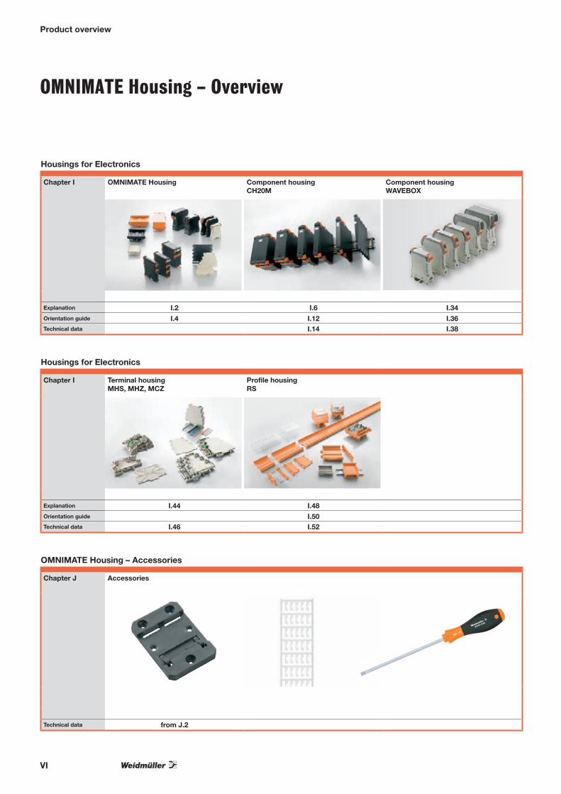
OMNIMATE Housing – Overview
Product overview
Housings for Electronics
Chapter I OMNIMATE Housing Component housingCH20M
Component housingWAVEBOX
Explanation I.2 I.6 I.34Orientation guide I.4 I.12 I.36Technical data I.14 I.38
Housings for Electronics
Chapter I Terminal housing MHS, MHZ, MCZ
Profile housing RS
Explanation I.44 I.48Orientation guide I.50Technical data I.46 I.52
OMNIMATE Housing – Accessories
Chapter J Accessories
Technical data from J.2

Intr
od
ucti
on
A
A.1
Contents
Introduction
Introduction OMNIMATE – Device connectivity and electronics housings Products, service and support A.2
Intr
od
ucti
on
A
A.2
OMNIMATE – Device connectivity and electronics housingsProducts, service and support
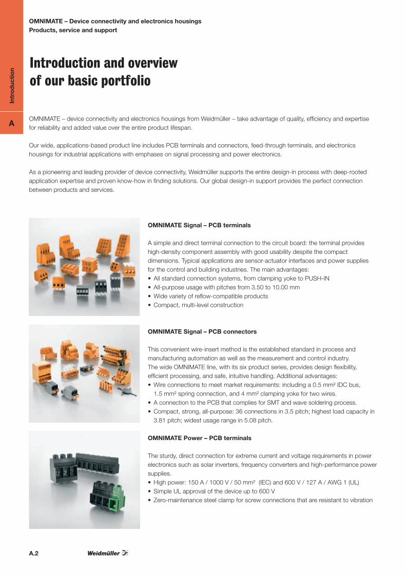
Introduction and overview of our basic portfolio
OMNIMATE Signal – PCB terminals
A simple and direct terminal connection to the circuit board: the terminal provides high-density component assembly with good usability despite the compact dimensions. Typical applications are sensor-actuator interfaces and power supplies for the control and building industries. The main advantages:• All standard connection systems, from clamping yoke to PUSH-IN• All-purpose usage with pitches from 3.50 to 10.00 mm• Wide variety of reflow-compatible products• Compact, multi-level construction
OMNIMATE Power – PCB terminals
The sturdy, direct connection for extreme current and voltage requirements in power electronics such as solar inverters, frequency converters and high-performance power supplies.• High power: 150 A / 1000 V / 50 mm² (IEC) and 600 V / 127 A / AWG 1 (UL)• Simple UL approval of the device up to 600 V• Zero-maintenance steel clamp for screw connections that are resistant to vibration
OMNIMATE Signal – PCB connectors
This convenient wire-insert method is the established standard in process and manufacturing automation as well as the measurement and control industry. The wide OMNIMATE line, with its six product series, provides design flexibility, efficient processing, and safe, intuitive handling. Additional advantages:• Wire connections to meet market requirements: including a 0.5 mm² IDC bus,
1.5 mm² spring connection, and 4 mm² clamping yoke for two wires. • A connection to the PCB that complies for SMT and wave soldering process.• Compact, strong, all-purpose: 36 connections in 3.5 pitch; highest load capacity in
3.81 pitch; widest usage range in 5.08 pitch.
OMNIMATE – device connectivity and electronics housings from Weidmüller – take advantage of quality, efficiency and expertise for reliability and added value over the entire product lifespan.
Our wide, applications-based product line includes PCB terminals and connectors, feed-through terminals, and electronics housings for industrial applications with emphases on signal processing and power electronics.
As a pioneering and leading provider of device connectivity, Weidmüller supports the entire design-in process with deep-rooted application expertise and proven know-how in finding solutions. Our global design-in support provides the perfect connection between products and services.

Intr
od
ucti
on
A
A.3
OMNIMATE – Device connectivity and electronics housingsProducts, service and support
OMNIMATE Power – PCB connectors
The pluggable connection method for modern drive systems and high-power electronics such as motor starters, inverters, servo drives and frequency converters. OMNIMATE Power sets the new standard – with increased safety and innovative solutions such as the pluggable shield, integrated signal contacts and one-handed operation.• Applications-based scalability: ranging from the compact 4 mm² connection for
29 A, to the sturdy 16 mm² connection for 50 kVA (IEC).• Unlimited usage up to 600V (UL) or 1000 V (IEC)
OMNIMATE Power – WGK through panel terminals
The logical expansion of the portfolio to include direct through panel connectors for device panels. Excellent for applications such as EMC filters, discrete-built inverters for drive systems and encapsulated devices. A wide variety of applications made possible with:• Wide power range for currents from 32 to 232 A and wire cross-sections from
4 to 95 mm² (AWG 4/0)• Various types of connections: solder connection, cable-lug-stud connection, and
clamping yoke screw connection.• Shapes for accommodating horizontal or vertical wire outlets
OMNIMATE Housing – Electronics housings
The perfect platform for form and function: Weidmüller‘s electronics housings provide a state-of-the-art platform for applications such as I/O sliced-design terminals, interface units, signal conditioners and power supplies. The portfolio covers all applications in the electrical cabinet, for example • Component housing like the modular CH20M system for an individual design,
efficient SMT processing and innovative use - scalable from 6 to 67 mm• Profile cases for special designs and small batches with 6 widths in variable or
modular configurations.
Individual services
The services described here are a perfect supplement to the basic portfolio – simple and quick to configure and tailor-made for your individual requirements. You can benefit from our decades of experience and innovative technologies.
Intr
od
ucti
on
A
A.4
OMNIMATE – Device connectivity and electronics housingsProducts, service and support
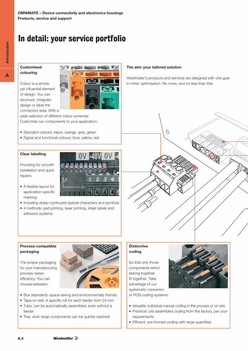
The aim: your tailored solution
Weidmüller‘s products and services are designed with one goal in mind: optimisation. No more, and no less than this.
Customised colouring
Colour is a simple yet influential element of design. You can structure, integrate, design or label the connection area. With a wide selection of different colour schemes Customise our components to your application:
• Standard colours: black, orange, grey, green• Signal and functional colours: blue, yellow, red
Clear labelling
Providing for smooth installation and quick repairs:
• A flexible layout for application-specific marking
• Including sharp-contoured special characters and symbols• 4 methods: pad printing, laser printing, inkjet labels and
adhesive systems
Distinctive coding
So that only those components which belong together fit together: Take advantage of our systematic connector or PCB coding systems:
• Versatile: individual manual coding in the process or on-site• Practical: pre-assembled coding from the factory, per your
requirements• Efficient: pre-formed coding with large quantities
Process-compatible packaging
The proper packaging for your manufacturing process raises efficiency. You can choose between:
• Box (standard): space saving and environmentally friendly• Tape on reel: A specific roll for each feeder from 24 mm• Tube: can be automatically assembled, even without a
feeder• Tray: even large components can be quickly reached
In detail: your service portfolio

Intr
od
ucti
on
A
A.5
OMNIMATE – Device connectivity and electronics housingsProducts, service and support
Application-oriented contact platings
Specify the proper contact platings – based on the electrical parameters and dependent on:
• Environmental conditions such as moisture level• Mechanical factors such as vibration• Application characteristics such as the number of plugging
cycles• Thermal influences such as temperature values and cycles
Selective assembly
Extend the clearance and creepage distances with a check box – partial assembly is simple and:
• Space saving: smaller dimensions than a large pitch • Efficient: different voltage ranges in one component• Economical: possible to use lower performance classes
Weidmüller‘s design-in partnership – more than just contacts.
• More design freedom, clearer differentiation, greater degree of innovation
• Less overhead, less compromises, a shorter time to market• Consistently reliable, maintenance-free, secure connections
The result: satisfied customers, greater success.
Pin lengths optimised for the process
Choose the ideal pin length based on engineering requirements and process parameters, including:
• Circuit board construction: thickness, assembly type• Assembly process: manual or automatic• Soldering process: wave or reflow soldering
Application-specific development
Seamlessly proceeding with your custom configuration: In addition to our technical and production expertise, Weidmüller‘s principle of ”pro-active design-in“ ensures that your solution will always be integrated into your project and application.
http://galaxy.weidmueller.com

Intr
od
ucti
on
A
A.6
OMNIMATE – Device connectivity and electronics housingsProducts, service and support
Six simple steps to reach your goal with twice the efficiency: your customised solution with service plus support.
Take advantage of our service and support combination for optimising your design-in process – from the specification stage to component integration.
Product specification Component selection Solution configuration
SERV
ICES
SUPP
ORT
Support from the start: the basic selection
Competent support all the way from selection to certification. This includes:• on-line internet help• with complete engineering data• working with a competent representativeThe start is simple – use the product configuration program at http://catalog.weidmueller.com to select from our basic products.
Your options to upgrade: the complete accessory portfolio
Supplement your basic components with additional functions:• The basis: your requirements• The advantage: integrated accessories• The result: applications-based functional
assemblies – and also completely pre-assembled sets when needed.
Just about everything else you‘ll need.
Freedom of design: our versatile services portfolio
Selection with your application in mind. Your choice of:• Design: housing colour and labelling• Function: contacts, coding, etc.• Construction: pin length, assembly • Process: packaging and processing
(solder process, connection method, etc.)To the point: integration through configuration.
All just one click away: the basic configuration
Rated data: pre-specified.Basic components: just selected. Characteristics: will now be configured:• Pole count: specified with a click• Solder pin length: easy to modify• Colour: displayed realistically• Contact surfaces: completely galvanised• Packaging: fully automated
Check it off and go: detailed configuration
Select and check it – finely tuned to ensure safe handling in the field: • Coding: for safe assignments • Assembly: with doubled pitch spacing• Labelling: clearly identifiedOptions: printing method, printing colour and orientation (alignment) of the print/symbols.
Your starting point: our comprehensive standard portfolio
The market standard for quality, efficiency and innovation – this is our contribution towards your success The result:• Better planning certainty with our
applications-based basic portfolio• Speedier integration with our custom
connection solutions • Customised modifications

Intr
od
ucti
on
A
A.7
OMNIMATE – Device connectivity and electronics housingsProducts, service and support
Solution verification Adapting to the application Solution integration
The basis for decision: the TARGET-balance
From concept, via model to the prototype: supplement our CAD support and verify your design with our prototype service. This includes:• A reference prototype from stock• Configurable prototype if needed• Fast prototyping for individualistsEnsuring that the solutions fits.
Tailor made: with individual development
Do you need more than just the standard plus configuration? Together we develop a solution based on your particular requirements. Our tailor-made solutions benefit from our decades of experience, innovative technologies, and modern processes (such as fast prototyping). It will fit like a glove.
The result: an exact solution
You can use our service for a configuration or a modification, including:• Innovative solutions• Shorter project duration• More efficient manufacturing processesTake advantage of applications-based functionality and quality – so that your customers, and not your products, return.
Convenient availability: the product database
Your data pool for construction, verification and documentation: with the relevant data sheets, drawings, 3-D models and more – in all standard formats – directly linked to the product during your search or configuration. For viewing, printing, downloading or e-mail.
Helping with words and deeds: proactive design-in
A reliable, helpful staff: on-line resources plus ”Human Resources“, i.e. a web assistant and your personal contact. You benefit from: • constructive team work • excellent application competence • A consistent solutions-oriented approach
Open-ended support: a partnership. Powered by Weidmüller
We‘re not satisfied until you are. Our commitment does not stop after the delivery. We support you:• from the market launch• to special customer requests and
we stay by your side to solve your problems.
http://galaxy.weidmueller.com

Intr
od
ucti
on
A
A.8
OMNIMATE – Device connectivity and electronics housingsProducts, service and support
Connection system
Clamping yoke screw connection
The clamping-yoke connection is the most used screw connection in the world. Steel clamping-yokes made of using a stamping and bending process guarantee a vibration proof clamp connection. When the screw on the clamp is tightened, there is a counter effect in the clamping yoke‘s threaded area which prevents the connection accidentally loosening. As the screw thread is on an inclined plane, there is a force gain created and a very high clamping force is achieved. Weidmüller uses hardened steel with optimal corrosion protection for stability and security and copper alloys in the contact area for good electrical conductivity.
Customer benefits:
• The screw connection guarantees a globally accepted, vibration proof and maintenance free connection.
• A large conductor clamping area is covered.• The ”Wire Ready“ technology ensures that the terminal points
are fully open at delivery, even after being transported world-wide
• The ”Wire Guard“ protection mechanism prevents accidental insertion of the wire underneath the clamping area which can be dangerous, it protects against hidden faulty contacts
• The flat clamping yoke also enables the clamping of very small cross-section wires
Field of application:
The standard connection for applications in industrial environments with the highest requirements for reliability even under harsh conditions.
PUSH IN spring connection
The PUSH IN spring connection with direct plug-in technology allows the fastest wiring process: the stripped or prepared wire is simply pushed into the terminal point as far as it will go and the connection is finished. Operating the release lever is only required with very standard wire or to release the connection. The stainless steel spring ensures a high contact force between wire and the tinned copper busbar. A stainless steel cage enclosure prevents subsidence in the contact area. To prevent any drop in clamping force plastic parts were deliberately not used.
Customer benefits:
• Fast, tool-less wire connection with direct insertion technology• The stainless steel spring results in a vibration-resistant
connection• Higher resistance to wire pull-out than in a tension clamp
system• Constant conductor clamping force independent of the
operator• Operator error is reduced using a colour-coded and intuitive
actuator• Wire feed and the operation are aligned in the same direction
which permits a compact equipment design
Field of application:
The default choice for operation in the field, it permits speedy wiring and, combined with its small size, its intuitive use is also advantageous even in environments with severe vibration.

Intr
od
ucti
on
A
A.9
TOP screw connection terminal with Pull-Effect
In the traditional case, the screw is always at a right angle to the conductor outlet direction, the TOP connection however, allows wire insertion and the screw orientation in the same direction. The TOP connection produces the greatest possible packing density in the terminal area. The ”pull effect“ ensures that the connected wire is pulled in to the clamping point producing a secure contact.
Customer benefits:
• The “pull effect” pulls the wire into the terminal point. Problems with clearance and creepage distances are avoided.
• Wire feed and the operation are aligned in the same direction which permits a compact equipment design
• The minimum installation height results in an extremely high packing density
Field of application:
Housing design or installation requirements such as PCB slots, that do not allow a right angled screw operation for reasons of space
Tension clamp connection
The pre-tensioned tension clamp is made from high quality rust and acid resistant steel, pulls the wire against the galvanised copper busbar, this results in a permanent and vibration resistant connection. The spring can be opened with a screwdriver. The wire is fed through the wire guide into the spring cage. When the screwdriver is removed, the wire is clamped. The surface-treated busbar ensures low contact resistance and a high resistance to corrosion.
Customer benefits:
• Constant conductor clamping force independent of the operator
• Wide-spread connection technology• Simple operation using a screwdriver or the integrated
release lever
Field of application:
Fast wiring with a constant clamping force, even in environments with severe vibration.
OMNIMATE – Device connectivity and electronics housingsProducts, service and support
Intr
od
ucti
on
A
A.10
OMNIMATE – Device connectivity and electronics housingsProducts, service and support
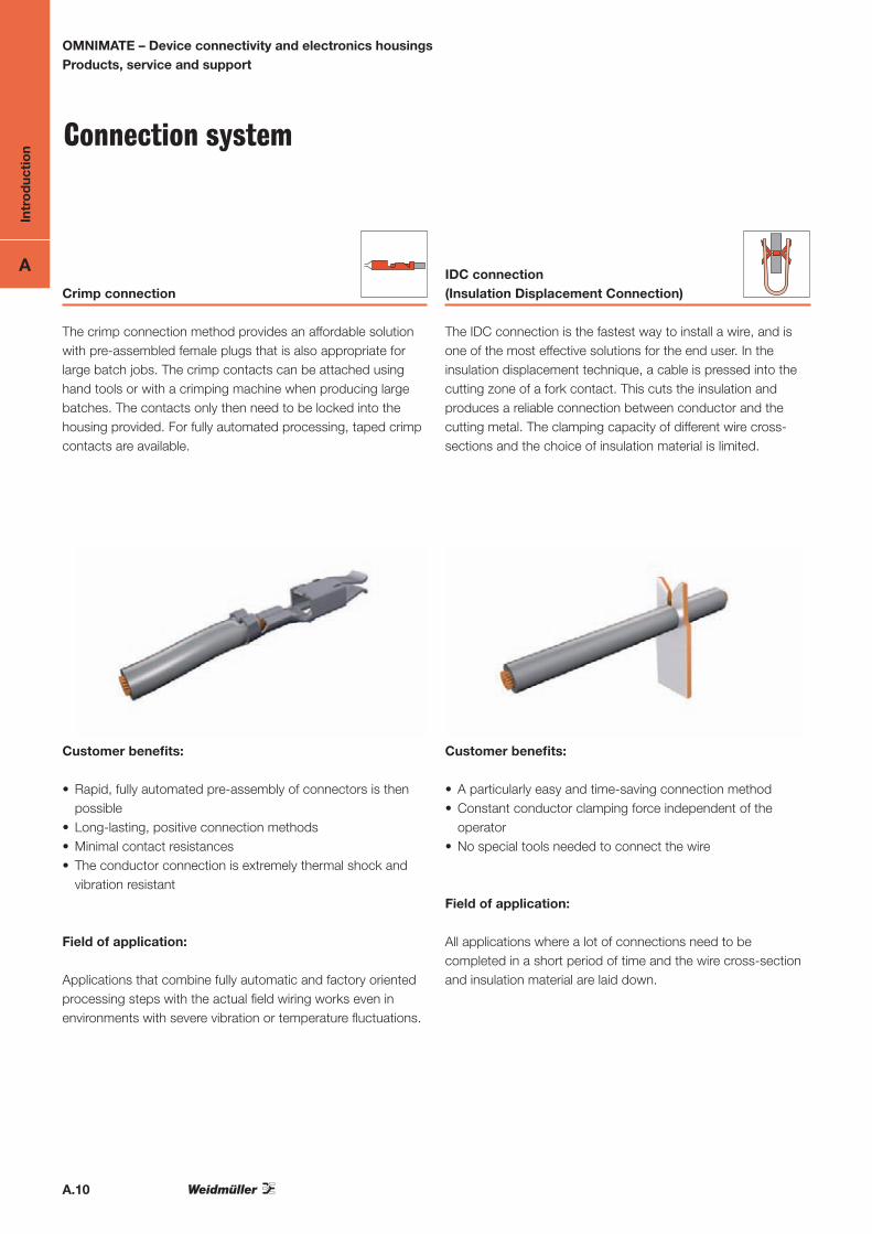
Connection system
Crimp connection
The crimp connection method provides an affordable solution with pre-assembled female plugs that is also appropriate for large batch jobs. The crimp contacts can be attached using hand tools or with a crimping machine when producing large batches. The contacts only then need to be locked into the housing provided. For fully automated processing, taped crimp contacts are available.
Customer benefits:
• Rapid, fully automated pre-assembly of connectors is then possible
• Long-lasting, positive connection methods• Minimal contact resistances • The conductor connection is extremely thermal shock and
vibration resistant
Field of application:
Applications that combine fully automatic and factory oriented processing steps with the actual field wiring works even in environments with severe vibration or temperature fluctuations.
IDC connection (Insulation Displacement Connection)
The IDC connection is the fastest way to install a wire, and is one of the most effective solutions for the end user. In the insulation displacement technique, a cable is pressed into the cutting zone of a fork contact. This cuts the insulation and produces a reliable connection between conductor and the cutting metal. The clamping capacity of different wire cross-sections and the choice of insulation material is limited.
Customer benefits:
• A particularly easy and time-saving connection method• Constant conductor clamping force independent of the
operator• No special tools needed to connect the wire
Field of application:
All applications where a lot of connections need to be completed in a short period of time and the wire cross-section and insulation material are laid down.
Intr
od
ucti
on
A
A.11
OMNIMATE – Device connectivity and electronics housingsProducts, service and support
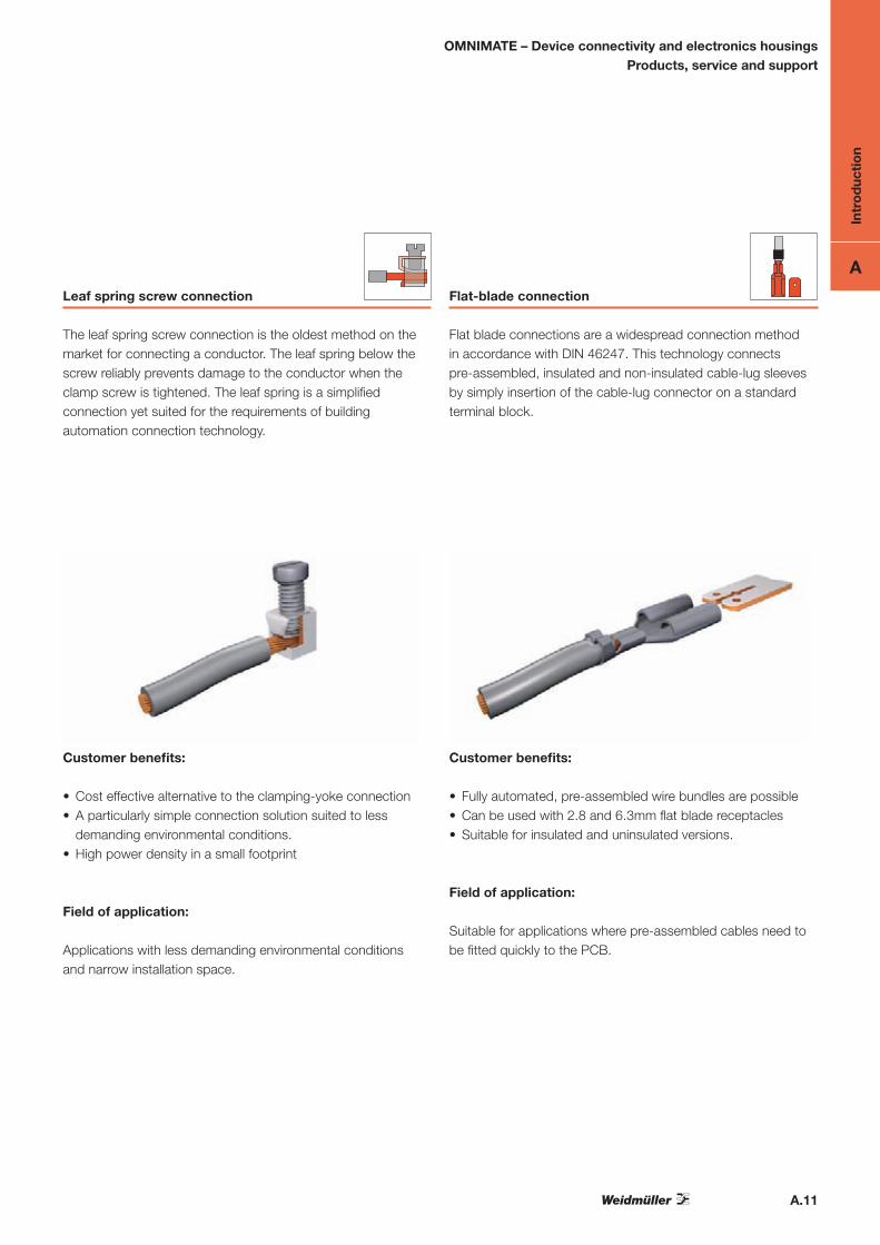
Leaf spring screw connection
The leaf spring screw connection is the oldest method on the market for connecting a conductor. The leaf spring below the screw reliably prevents damage to the conductor when the clamp screw is tightened. The leaf spring is a simplified connection yet suited for the requirements of building automation connection technology.
Customer benefits:
• Cost effective alternative to the clamping-yoke connection • A particularly simple connection solution suited to less
demanding environmental conditions.• High power density in a small footprint
Field of application:
Applications with less demanding environmental conditions and narrow installation space.
Flat-blade connection
Flat blade connections are a widespread connection method in accordance with DIN 46247. This technology connects pre-assembled, insulated and non-insulated cable-lug sleeves by simply insertion of the cable-lug connector on a standard terminal block.
Customer benefits:
• Fully automated, pre-assembled wire bundles are possible• Can be used with 2.8 and 6.3mm flat blade receptacles • Suitable for insulated and uninsulated versions.
Field of application:
Suitable for applications where pre-assembled cables need to be fitted quickly to the PCB.

Intr
od
ucti
on
A
A.12
OMNIMATE – Device connectivity and electronics housingsProducts, service and support
Flange option
O G B F / FI LF/LFI/FLF RF MF/MSF
Open ClosedDovetail
for B-Block
Flange
with nut
Flange
with nut
Clip-on flange
without nut (for
release latch)
Middle flange
with/
without nut
Attachment to the PCB No No
using
accessories
with nut
optional
screwSolder pin Solder pin
Solder pin
(partial)
Att
achm
ent
to t
he r
ail
Male connectors
Socket blocks
OM
NIM
AT
E S
igna
l and
Po
wer
G
Clo
sed
No
BD
ovet
ail
for
B-B
lock
abou
t bol
t-on
acce
ssor
ies
Fem
ale
plu
g
Mal
e p
lug
F
Flan
ge
Scr
ew
FIIn
vert
ed
flang
e
Nut
LH
Rel
ease
leve
r
No
LR
Rel
ease
latc
h
Tack
OM
NIM
AT
E P
ow
er
F
Flan
ge
Lock
ing
clas
p
FI/S
FI
Inve
rted
flan
ge
Sna
p ho
ok /
with
scr
ew
MF/
MSF
Mid
dle
flang
e
Sna
p ho
ok /
with
scr
ew
= recommended
= possible to a limited extent