2011 supplies moulding - onsitecatalog.com · introduction welcome to this second edition of the...
TRANSCRIPT

Moulding Supplies2011
www.mouldpro.com
Cat. Version 2011/1
Moulding Supplies
2011
Cat. Version 2011/1
Mouldpro Cover 2011 FINAL.indd 1 31/1/11 21:28:42

IntroductIonWelcome to this second edition of the MOULDPRO catalogue full of products dedicated to the Plastic Injection Moulding Industry. MOULDPRO is committed to supplying high quality products at competitive prices. By listening to your ideas you will notice that we have added many new and innovative products that compli-ment our first catalogue. MOULDPRO offers a comprehensive range of pro-ducts for injection moulding professionals, inclu-ding mould sprays, consumables, water couplings, specialist tools and accessories which are available through our network of carefully selected distri-butors who can offer you expert knowledge and share our commitment to customer service.
MOULDPRO is a new name – but, brings together many years of experience in the plastics industry – Our strategy is to bring you the high quality produ-cts that you need when you need them – offering good value for money and through our Internatio-nal distribution network we are able to offer a true global presence to the plastics industry. We hope that you will find a suitable product for your application in this catalogue and look forward to your feedback, as your satisfaction is our incen-tive to improve ourselves a little everyday.

1 Mould Cooling & Flow
2 Consumables
3 Heaters & Temperature Control
4 Material Handling
5 End of Arm Tooling
6 End of Barrel
7 Tools & Accessories
8 Machine Accessories
9 Lifting
contEntS
4
01. Mould coolIng & Flow
Couplers
Hoses
Ball Valves
Manifolds
Regulators
Flow Indicator
Pressure Test Unit
PTFE Tape
De-Scaling
Sealants

5
S Series A D L L1 SW VPE20 20K6V 20K6 6 18 46 17 10
20K10V 20K10 10 18 51 22 1030 30K10V 30K10 10 24 64 22 10
30K13V 30K13 13 24 66,5 25 1050 50K19V 50K19 19 32 89 32 5
S Series A D L L1 SW VPE20 20K6V-S 20K6-S 6 18 54 17 10
20K10V-S 20K10-S 10 18 59 22 1030 30K10V-S 30K10-S 10 24 73 22 10
30K13V-S 30K13-S 13 24 76 25 10
S Series A D L L1 SW VPE20 20K6V/90 20K6/90 6 18 40 19 10
20K10V/90 20K10/90 10 18 40 22 1030 30K10/90V 30K10/90 10 24 56 22 10
30K13/90V 30K13/90 13 24 56 28,5 1050 50K19V/90 50K19/90 19 32 77 32 5
S Series A D L L1 SW VPE20 20K10V/90-S 20K10/90-S 10 18 52,5 22 1030 30K10V/90-S 30K10/90-S 10 24 68,5 22 10
30K13V/90-S 30K13/90-S 13 24 68,5 28,5 10
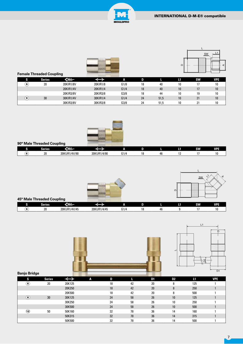
INTERNATIONAL D-M-E® compatible
Straight Coupling
Safe-Lock™ Safety coupling
Safe-Lock™ Safety coupling
90° Coupling

6
S Series A D L L1 SW VPE20 20K6V/45 20K6/45 6 18 55,5 19 10
20K10V/45 20K10/45 10 18 55,5 22 1030 30K10/45V 30K10/45 10 24 71 22 10
30K13/45V 30K13/45 13 24 75 25 1050 50K19/45V 50K19/45 19 32 77 30 5
S Series A D L L1 SW VPE20 20K10V/45-S 20K10/45-S 10 18 51,5 22 1030 30K10V/45-S 30K10/45-S 10 24 65,5 22 10
30K13V/45-S 30K13/45-S 13 24 65,5 25 10
S Series A D L L1 SW VPE20 20KUR1/4V 20KUR1/4 G1/4 18 47 9 17 10
20KUR3/8V 20KUR3/8 G3/8 18 47 9 19 1030 30KUR1/4V 30KUR1/4 G1/4 24 56,5 9 22 10
30KUR3/8V 30KUR3/8 G3/8 24 56,5 9 22 1030KUR1/2V 30KUR1/2 G1/2 24 59,5 12 22 10
50 50KUR1/2V 50KUR1/2 G1/2 32 73 12 30 1050KUR3/4V 50KUR3/4 G3/4 32 77 16 30 5
S Series A D L L1 SW VPE20 20KUR1/4V-S 20KUR1/4-S G1/4 18 51,5 9 17 10
20KUR3/8V-S 20KUR3/8-S G3/8 18 51,5 9 19 1030 30KUR1/4V-S 30KUR1/4-S G1/4 24 67 9 22 10
30KUR3/8V-S 30KUR3/8-S G3/8 24 67 9 22 1030KUR1/2V-S 30KUR1/2-S G1/2 24 70 12 22 10
INTERNATIONAL D-M-E® compatible
45° Coupling
Male Threaded Coupling
Safe-Lock™ Safety coupling
Safe-Lock™ Safety coupling
7
INTERNATIONAL D-M-E® compatible
S Series A D L L1 SW VPE20 20KIR1/8V 20KIR1/8 G1/8 18 40 10 17 10
20KIR1/4V 20KIR1/4 G1/4 18 40 10 17 1020KIR3/8V 20KIR3/8 G3/8 18 44 10 19 10
30 30KIR1/4V 30KIR1/4 G1/4 24 51,5 10 21 1030KIR3/8V 30KIR3/8 G3/8 24 51,5 10 21 10
S Series A D L L1 SW VPE20 20KUR1/4V/90 20KUR1/4/90 G1/4 18 46 12 17 10
S Series A D L D1 D2 L1 VPE20 20K125 18 42 20 8 125 1
20K250 18 42 20 8 250 120K500 18 42 20 8 500 1
30 30K125 24 58 26 10 125 130K250 24 58 26 10 250 130K500 24 58 26 10 500 1
50 50K160 32 78 36 14 160 150K315 32 78 36 14 315 150K500 32 78 36 14 500 1
S Series A D L L1 SW VPE20 20KUR1/4V/45 20KUR1/4/45 G1/4 18 46 9 17 10
Female Threaded Coupling
90° Male Threaded Coupling
45° Male Threaded Coupling
Banjo Bridge

8
S Series A D L L1 SW VPE20 20N100 R1/8 9,5 100 9 11 10
20N150 R1/8 9,5 150 9 11 1020N250 R1/8 9,5 250 9 11 10
30 30N150 R1/4 13,5 150 12 15 1030N250 R1/4 13,5 250 12 15 10
S Series A D L L1 SW VPE20 20NM10 M10x1 9,5 23 8 13 25
20NR1/8 R1/8 9,5 24 9 13 2520NR1/4 R1/4 9,5 29 12 16 25
20NR1/4V R1/4 9,5 29 14 16 2520NR3/8 R3/8 9,5 30 12 19 25
30 30NR1/4V 30NR1/4 R1/4 13,5 34 12 16 2530NR3/8V 30NR3/8 R3/8 13,5 34 12 19 25
30NR1/2 R1/2 13,5 39 17 24 2550 50NR1/2 R1/2 20 44 17 22 10
50NR3/4 R3/4 20 45 19 29 10
S Series A D L L1 SW VPE20 20NR1/8/100 G1/8 9,5 100 60 11 10
20NR1/4/100 G1/4 9,5 100 60 14 1030 30NR1/4/100 G1/4 13,5 100 60 14 10
30NR3/8/100 G3/8 13,5 100 60 17 10
INTERNATIONAL D-M-E® compatible
Male Plug
Adjustable Plug
Extended Plug

9
S Series A D L L1 SW VPE20 20N10 10 9,5 39 22 2530 30N13 13 13,5 41 21 2550 50N19 19 20 91 46 10
Part No. Series S200V 20300V 30500V 50
S Series A D L L1 SW VPE20 20NR1/8I G1/8 9,5 28 11 13 25
20NR1/4I G1/4 9,5 32 13 16 2520NR3/8I G3/8 9,5 34 13 19 25
30 30NR1/4I G1/4 13,5 37 13 16 2530NR3/8I G3/8 13,5 39 13 19 25
S Series A D L L1 L2 SW VPE20 20NM10/90 M10x1 9,5 27 9 28,5 11 25
20NR1/8/90 R1/8 9,5 27 9 28,5 11 2520NR1/4/90 R1/4 9,5 27 9 28,5 11 25
30 30NR1/4/90 R1/4 13,5 34 9 32 15 2530NR3/8/90 R3/8 13,5 34 9 32 15 25
INTERNATIONAL D-M-E® compatible
Replacement Seals Viton +200° C
90° Male Plug
Hosetail Plug
Female Plug
10
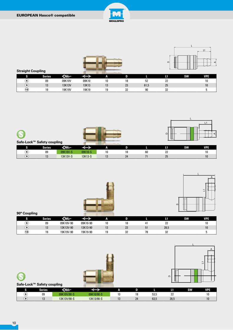
S Series A D L L1 SW VPE09 09K10V 09K10 10 18 52 22 1013 13K13V 13K13 13 23 61,5 25 1019 19K19V 19K19 19 32 90 32 5
S Series A D L L1 SW VPE09 09K10V-S 09K10-S 10 18 60 22 1013 13K13V-S 13K13-S 13 24 71 25 10
S Series A D L L1 SW VPE09 09K10V-90 09K10-90 10 18 41 22 1013 13K13V-90 13K13-90 13 23 51 28,5 1019 19K19V-90 19K19-90 19 32 78 32 5
1L
S Series A D L L1 SW VPE09 09K10V/90-S 09K10/90-S 10 18 53,5 22 1013 13K13V/90-S 13K13/90-S 13 24 63,5 28,5 10
EUROPEAN Hasco® compatible
Safe-Lock™ Safety coupling
Safe-Lock™ Safety coupling
Straight Coupling
90° Coupling

11
S Series A D L L1 SW VPE09 09K10V/45-S 09K10/45-S 10 18 60 22 1013 13K13V/45-S 13K13/45-S 13 24 60,5 25 10
S Series A D L L1 SW VPE09 09KUM14V 09KUM14 M14x1,5 18 48 9 17 10
09KUR1/4V 09KUR1/4 G1/4 18 48 9 17 1009KUR3/8V 09KUR3/8 G3/8 18 48 9 19 10
13 13KUM16V 13KUM16 M16x1,5 23 51,5 9 22 1013KUR1/4V 13KUR1/4 G1/4 23 51,5 9 22 1013KUR3/8V 13KUR3/8 G3/8 23 51,5 9 22 1013KUR1/2V 13KUR1/2 G1/2 23 54,5 12 22 10
19 19KUM24V 19KUM24 M24x1,5 32 78 16 30 519KUR1/2V 19KUR1/2 G1/2 32 74 12 30 519KUR3/4V 19KUR3/4 G3/4 32 78 16 30 5
S Series A D L L1 SW VPE09 09K10V-45 09K10-45 10 18 41 22 1013 13K13V-45 13K13-45 13 23 51 25 1019 19K19V-45 19K19-45 19 32 78 30 5
EUROPEAN Hasco® compatible
Safe-Lock™ Safety coupling
45° Coupling
Male Threaded Coupling

12
S Series A D L L1 SW VPE09 09KM14/90V 09KM14/90 M14x1,5 18 47 12 17 10
09KR1/4/90V 09KR1/4/90 G1/4 18 47 12 17 10
13 13KUM16V/90 13KM16/90 M16x1,5 23 53,5 12 22 10
19 19KUM24V/90 19KUM24/90 M24x1,5 32 80 18 30 5
S Series A D L L1 SW VPE09 09KM14/45V 09KM14/45 M14x1,5 18 47 9 17 10
09KR1/4/90V 09KR1/4/90 G1/4 18 47 9 17 1013 13KUM16V/45 13KUM16/45 M16x1,5 23 53,5 9 22 1019 19KUM24V/45 19KUM24/45 M24x1,5 32 80 18 30 5
L
D A
L1
S Series A D L L1 SW VPE09 09KIR1/4V 09KIR1/4 G1/4 18 41 10 17 10
09KIR3/8V 09KIR3/8 G3/8 18 45 10 19 1013 13KIR1/4V 13KIR1/4 G1/4 23 46,5 10 21 10
13KIR3/8V 13KIR3/8 G3/8 23 46,5 10 21 1013KIM16V 13KIM16 M16x1,5 23 46,5 10 21 10
S Series A D L L1 SW VPE09 09KUM14V-S 09KUM14-S M14x1,5 18 52,5 9 17 10
09KUR1/4V-S 09KUR1/4-S G1/4 18 52,5 9 17 1009KUR3/8V-S 09KUR3/8-S G3/8 18 52,5 9 19 10
13 13KUM16V-S 13KUM16-S M16x1,5 24 62 9 22 1013KUR1/4V-S 13KUR1/4-S G1/4 24 62 9 22 1013KUR3/8V-S 13KUR3/8-S G3/8 24 62 9 22 1013KUR1/2V-S 13KUR1/2-S G1/2 24 65 12 22 10
EUROPEAN Hasco® compatible
Safe-Lock™ Safety coupling
Female Threaded Coupling
90° Male Threaded Coupling
45° Male Threaded Coupling

13
Description: * Nickle plated
S Series D L D1 D2 L1 PE09 09K125 18 43 20 8 125 1
09K250 18 43 20 8 250 109K500 18 43 20 8 500 1
13 13K125 23 53 26 10 125 113K250 23 53 26 10 250 113K500 23 53 26 10 500 1
19 19K160 32 80 36 14 160 119K315 32 80 36 14 315 119K500 32 80 36 14 500 1
S Series A D L L1 SW VPE09 09NM8 M8x0,75 9 24 7 11 25
09NM10 M10x1 9 24 7 11 2509NR1/8* G1/8 9 24 7 11 2509NM12 M12x1,5 9 27 10 14 2509NM14 M14x1,5 9 26 9 15 25
09NM14V M14x1,5 9 29 12 15 2509NR1/4* G1/4 9 26 9 15 25
09NR1/4V* G1/4 9 29 12 15 2509NR3/8* G3/8 9 30 10 17 25
13 13NR1/8* G1/8 13,5 25 8 14 2513NM14 M14x1,5 13,5 26 9 15 2513NR1/4* G1/4 13,5 26 9 15 25
13NR1/4V* G1/4 13,5 31 12 15 2513NR3/8* G3/8 13,5 26 9 17 25
13NR3/8V* G3/8 13,5 30 12 17 2513NM16 M16x1,5 13,5 26 9 17 25
13NM16V M16x1,5 13,5 30 12 17 2519 19NM24V 19NM24 M24x1,5 19 51 16 27 10
19NR1/2* G1/2 19 47 12 22 1019NR3/4V* 19NR3/4* G3/4 19 51 16 27 10
EUROPEAN Hasco® compatible
Banjo Bridge
Male Plug

14
S Series A D L L1 SW VPE09 09NM8SS M8x0,75 9 24 7 11 25
09NM10SS M10x1 9 24 7 11 2509NR1/8SS G1/8 9 24 7 11 2509NR1/4SS G1/4 9 26 9 15 25
13 13NR1/4SS G1/4 13,5 26 9 15 2513NR3/8SS G3/8 13,5 26 9 17 25
S Series A D L L1 SW VPE09 09NR1/8/100 G1/8 9 100 60 11 10
09NR1/4/100 G1/4 9 100 60 14 1013 13NR1/4/100 G1/4 13,5 100 60 14 10
13NR3/8/100 G3/8 13,5 100 60 19 10
S Series A D L L1 SW VPE09 09N63 8 9 63 42 9 10
09N100 8 9 100 79 9 1009N120 10 9 120 100 11 1009N240 10 9 240 220 11 1009N360 10 9 360 340 11 10
13 13N150 14 13,5 150 125 15 1013N300 14 13,5 300 275 15 1013N450 14 13,5 450 425 15 10
19 19N500 21 19 500 465 22 519N800 21 19 800 765 22 5
EUROPEAN Hasco® compatible
Male Plug - Stainless Steel
Adjustable Plug
Extended Plug

15
Description: * Nickle plated
S Series A D L L1 L2 SW VPE09 09NM8/90 M8x0,75 9 27 9 28,5 11 25
09NM10/90 M10x1 9 27 9 28,5 11 2509NR1/8/90* R1/8 9 27 9 28,5 11 2509NR1/4/90* R1/4 9 27 9 28,5 11 25
13 13NM14/90 M14x1,5 13,5 34 11 32 15 2513NR1/4/90* R1/4 13,5 34 11 32 15 2513NR3/8/90* R3/8 13,5 34 11 32 15 25
19 19NM24/90 M24x1,5 19 47 16 54 24 519NR1/2/90* R1/2 19 47 16 54 24 5
S Series A D L L1 VPE09 09N10 10 9 38 22 2513 13N10 10 13,5 41 25 25
13N13 13 13,5 41 25 2519 19N13 13 19 61 32 5
19N19 19 19 61 32 5
S Series A D L L1 SW VPE09 09NR1/8I G1/8 9 24 7 11 25
09NR1/4I G1/4 9 27 8 16 2513 13NR1/4I G1/4 13,5 33 8 16 25
EUROPEAN Hasco® compatible
90° Male Plug
Hosetail Plug
Female Plug
16
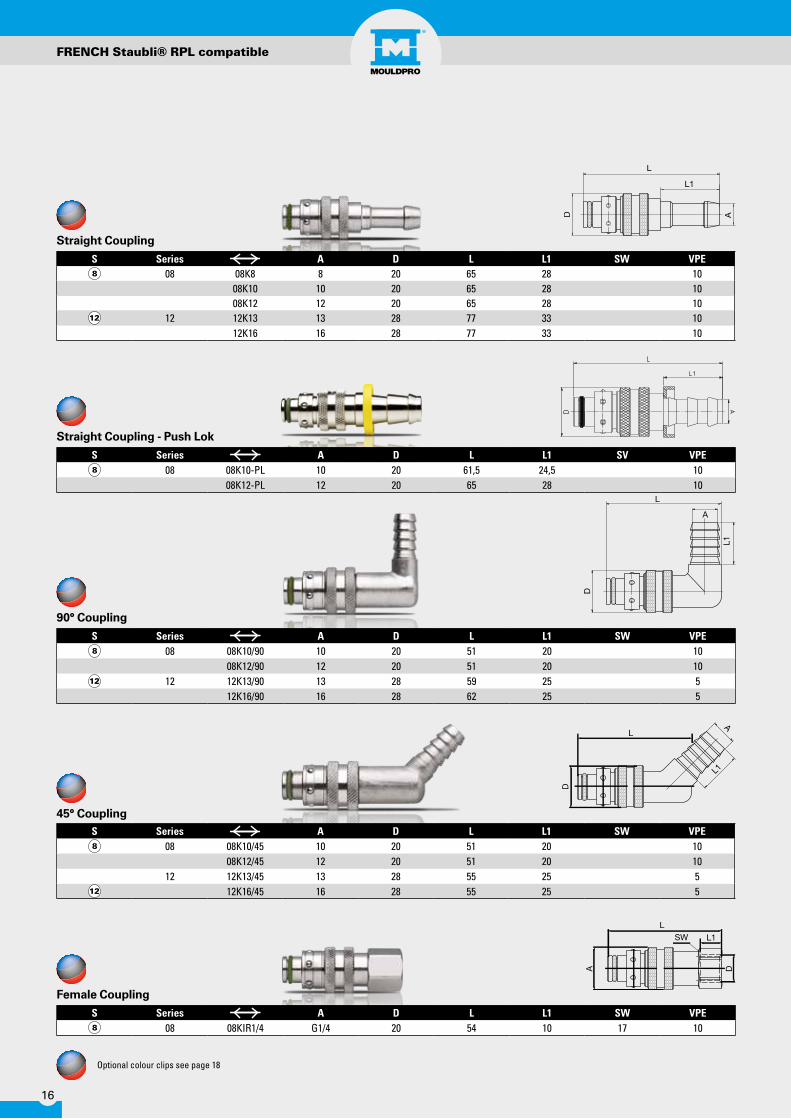
S Series A D L L1 SW VPE08 08K8 8 20 65 28 10
08K10 10 20 65 28 1008K12 12 20 65 28 10
12 12K13 13 28 77 33 1012K16 16 28 77 33 10
S Series A D L L1 SW VPE08 08K10/90 10 20 51 20 10
08K12/90 12 20 51 20 1012 12K13/90 13 28 59 25 5
12K16/90 16 28 62 25 5
S Series A D L L1 SW VPE08 08K10/45 10 20 51 20 10
08K12/45 12 20 51 20 1012 12K13/45 13 28 55 25 5
12K16/45 16 28 55 25 5
S Series A D L L1 SV VPE08 08K10-PL 10 20 61,5 24,5 10
08K12-PL 12 20 65 28 10
FRENCH Staubli® RPL compatible
Optional colour clips see page 18
S Series A D L L1 SW VPE08 08KIR1/4 G1/4 20 54 10 17 10
Straight Coupling
Straight Coupling - Push Lok
90° Coupling
45° Coupling
Female Coupling

17
S Series A D L L1 L2 SW VPE08 08NR1/8/90 R1/8 22 34 11 33 10
08NR1/4/90 R1/4 22 37 13 33 1008NR3/8/90 R3/8 22 37 13 33 10
Optional colour clips see page 18
S Series A D L L1 SW VPE08 08NM10 M10x1 21 32 10 6 25
08NR1/8 G1/8 21 32 10 6 2508NR1/4 G1/4 21 33 12 8 2508NR3/8 G3/8 21 24 13 8 25
12 12NR3/8 G3/8 32 41 13 10 1012NR1/2 G1/2 32 44 16 14 1012NR3/4 G3/4 32 32 19 14 10
S Series A D L L1 SW VPE08 08NR1/8I G1/8 21 35 10 6 10
08NR1/4I G1/4 21 40 14 8 1012 12NR3/8I G3/8 32 49 14 12 10
12NR1/2I G1/2 32 50 14 12 10
FRENCH Staubli® RPL compatible
S Series A D L L1 L2 SW VPE08 08NR1/8/45 R1/8 22 33 10,5 10
08NR1/4/45 R1/408NR3/8/45 R3/8 22 35 13 10
Male Plug
Female Plug
90° Plug
45° Plug

18
Series Part No. Colour VPEColour Clip for couplers/ für Kupplungen/pour coupleurs 08 08KR 10Colour Clip for couplers/ für Kupplungen/pour coupleurs 08KB 10Colour Clip for couplers/ für Kupplungen/pour coupleurs 08KS 10Colour Clip for couplers/ für Kupplungen/pour coupleurs 12 12KR 10Colour Clip for couplers/ für Kupplungen/pour coupleurs 12KB 10Colour Clip for couplers/ für Kupplungen/pour coupleurs 12KS 10
Series Part No. Colour VPEColour Clip for connectors/ für Stecknippel /pour abouts 08 08NR 10Colour Clip for connectors/ für Stecknippel /pour abouts 08NB 10Colour Clip for connectors/ für Stecknippel /pour abouts 08NS 10Colour Clip for connectors/ für Stecknippel /pour abouts 12 12NR 10Colour Clip for connectors/ für Stecknippel /pour abouts 12NB 10Colour Clip for connectors/ für Stecknippel /pour abouts 12NS 10
S Series A D L L1 SW VPE08 08NR1/8/50 G1/8 21 50 28 6 10
08NR1/8/100 G1/8 21 100 60 6 1008NR1/8/150 G1/8 21 150 60 6 1008NR1/4/50 G1/4 21 50 28 8 1008NR1/4/100 G1/4 21 100 60 8 1008NR1/4/150 G1/4 21 150 60 8 1008NR1/4/200 G1/4 21 200 60 8 10
FRENCH Staubli® RPL compatible
Part No. Series S08V 8
12V 12
Replacement Seals Viton +200° C
Extended Plug
Coupling Colour Tags
Plug Colour Tags
19
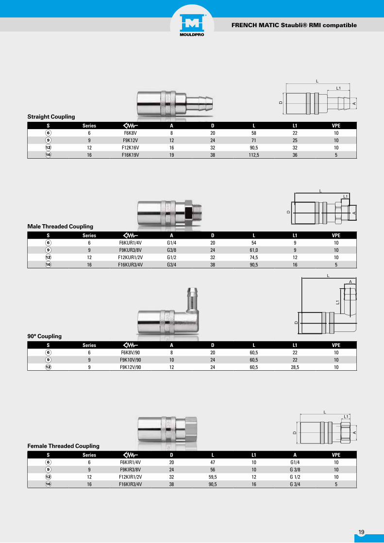
S Series A D L L1 VPE6 F6K8V 8 20 58 22 109 F9K12V 12 24 71 25 1012 F12K16V 16 32 90,5 32 1016 F16K19V 19 38 112,5 36 5
S Series A D L L1 VPE6 F6KUR1/4V G1/4 20 54 9 109 F9KUR3/8V G3/8 24 61,0 9 1012 F12KUR1/2V G1/2 32 74,5 12 1016 F16KUR3/4V G3/4 38 90,5 16 5
S Series A D L L1 VPE6 F6K8V/90 8 20 60,5 22 109 F9K10V/90 10 24 60,5 22 109 F9K12V/90 12 24 60,5 28,5 10
S Series D L L1 A VPE6 F6KIR1/4V 20 47 10 G1/4 109 F9KIR3/8V 24 56 10 G 3/8 1012 F12KIR1/2V 32 59,5 12 G 1/2 1016 F16KIR3/4V 38 90,5 16 G 3/4 5
FRENCH MATIC Staubli® RMI compatible
Straight Coupling
Male Threaded Coupling
90° Coupling
Female Threaded Coupling

20
S Series A D L L1 SW VPE6 F6NR1/8V G1/8 9,4 45 7 17 109 F9NR1/4V G 1/4 13,8 49 9 19 10
F9NR3/8V G 3/8 13,8 47 9 24 10F9NR1/2V G 1/2 13,8 50 12 27 10
12 F12NR3/8V G 3/8 17,8 61 9 24 10F12NR1/2V G 1/2 17,8 62 12 27 10F12NR3/4V G 3/4 17,8 64 16 34 10
16 F16NR3/4V G 3/4 22,4 81 16 34 5F16NR1/1V G 1 22,4 84 19 41 5
S Series A D L L1 SW VPE6 F6NR1/8 G1/8 10 30 9 5 109 F9NR1/4 R 1/4 BSPT 13,8 35 12 8 10
F9NR3/8 R 3/8 BSPT 13,8 35 12 8 1012 F12NR3/8 R 3/8 BSPT 17,8 40 12 10 10
S Series A D L L1 SW VPE12 F12NR1/2 R 1/2 BSPT 17,8 42 17 22 1016 F16NR3/4 R 3/4 BSPT 22,4 59 19 27 10
S Series A D L L1 SW VPE9 F9NR1/2V-S G 1/2 13,8 37 12 22 1012 F12NR3/4V-S G 3/4 17,8 46 16 27 1016 F16NR1/1V-S G 1 22,4 58 20 32 10
FRENCH MATIC Staubli® RMI compatible
Valed Plug
Male Plug with Innner Hex
Male Plug Taper Thread
Valved Plug Short Model

21
S Series A D L L1 SW VPE9 F9NR1/2 G 1/2 BSP 13,8 37 12 22 1012 F12NR3/4 G 3/4 BSP 17,8 46 16 27 10
S Series A D L L1 SW VPE6 F6NR1/4I G1/4 9,4 34 11 17 109 F9NR3/8I G 3/8 13,8 37 10 22 1012 F12NR1/2I G 1/2 17,8 45 12 27 1016 F16NR3/4I G 3/4 22,4 58 16 32 5
S Series A D L L1 SW VPE6 F6NR1/8VI G1/8 9,4 47 7 17 109 F9NR1/4VI G 1/4 13,8 46 10 19 10
F9NR3/8VI G 3/8 13,8 48 10 22 1016 16NR3/4VI G 3/4 22,4 80,5 16 32 5
FRENCH MATIC Staubli® RMI compatible
Male Plug
Female Plug
Female Plug Valved

22
Material EPDM
Material EPDM
Material NBR
°C+150°C
°C
°C
+164°C
+100°C
Part No. D1 D L Colour Pressure VPEN10S 10 16,5 50 m max. 15 bar 1N13S 13 21 50 m max. 15 bar 1
HOSES
Part No. D1 D L Colour Pressure VPEG10B 10 16,5 50 m Max 15 bar 1G10R 10 16,5 50 m Max 15 bar 1G10S 10 16,5 50 m Max 15 bar 1G13B 13 21 50 m Max 15 bar 1G13R 13 21 50 m Max 15 bar 1G13S 13 21 50 m Max 15 bar 1G19B 19 27 30 m Max 15 bar 1G19R 19 27 30 m Max 15 bar 1G19S 19 27 30 m Max 15 bar 1
Part No. D1 D L Colour Pressure VPEE10B 10 16,5 50 m max. 15 bar 1E10R 10 16,5 50 m max. 15 bar 1E10S 10 16,5 50 m max. 15 bar 1E13B 13 21 50 m max. 15 bar 1E13R 13 21 50 m max. 15 bar 1E13S 13 21 50 m max. 15 bar 1E19B 19 27 30 m max. 15 bar 1E19R 19 27 30 m max. 15 bar 1E19S 19 27 30 m max. 15 bar 1

23
Description: Stainless Steel Braided
Description: Stainless Steel Braided
Part No. D1 D L Colour Pressure VPEP10T 10 16 30 m max. 15 bar 1P10B 10 16 30 m max. 15 bar 1P10R 10 16 30 m max. 15 bar 1P13T 13 21 30 m max. 15 bar 1P13B 13 21 30 m max. 15 bar 1P13R 13 21 30 m max. 15 bar 1P19T 19 27 30 m max. 15 bar 1P19B 19 27 30 m max. 15 bar 1P19R 19 27 30 m max. 15 bar 1
Material PVC
Material SILICONE
Material FKM
°C °C °CWater Oil Temperature max.
°C
°C
+60°C
+170°C
°C+200°C
°C
Part No. D1 D L Colour Pressure VPES10 10 15 25 m max. 15 bar 1
S10B 10 15 25 m max. 15 bar 1S10R 10 15 25 m max. 15 bar 1S13 13 19 25 m max. 15 bar 1
S13B 13 19 25 m max. 15 bar 1S13R 13 19 25 m max. 15 bar 1
HOSES
Part No. D1 D L Colour Pressure VPEV10 10 15 25 m max. 15 bar 1V13 13 19 25 m max. 15 bar 1

24
PTFE Hose assemblies
Part No. A L Hose IDT10300R1/4 1/4 BSPP 300 10T10600R1/4 600T10800R1/4 800
T101000R1/4 1000T101250R1/4 1250T101500R1/4 1500T102000R1/4 2000T10300M14 M14X1,5 300 10T10600M14 600T10800M14 800
T101000M14 1000T101250M14 1250T101500M14 1500T102000M14 2000T13300M16 M16X1,5 300 10T13600M16 600T13800M16 800
T131000M16 1000T131250M16 1250T131500M16 1500T132000M16 2000T13300R3/8 3/8 BSPP 300 13T13600R3/8 600T13800R3/8 800
T131000R3/8 1000T131250R3/8 1250T131500R3/8 1500T132000R3/8 2000
Description: Super Flex convoluted inner tube/ Stainless steel braidedMax 20 Bar pressure
HOSES
°C+260°C
°C
Part No. D VPEX100 10-36 1
Hand Crimper

25
HOSE CLAMPS
Part No. D d VPE Hose Ref.C10/15 15 10 100 S10C10/16 16 10 100 V10/P10C10/17 17 10 100 G10/E10C13/19 19 13 100 S13/V13/P13C13/22 22 13 100 G13/E13C29/19 29 19 50 G19/E19
Description: Ferrules made of Stainless Steel. Offers perfect and safe connections.
Part No. D d VPEK8 9-12 8 50
K10 10-17 10 50K13 12-22 13 50K19 22-32 19 50
Two-ear clip
Description: Two-ear clips is an economical solution for simple hose assemblies. The two ears give the clip extra grip and help to maintain constant pressure around the hose. Two-ear clips offer great versatility in simple hose assemblies.Material: St 34 steel : Finish Silver-white Cr3 Zinc-Plated
Part No. ø - ID L VPE HOSE RefEAR15 13-15 7 100 S10/V10EAR17 14-17 7 100 P10EAR18 15-18 7,5 100 E10/G10EAR20 17-20 7,5 100 S13/V13/P13EAR23 20-23 8,5 100 E13/G13EAR27 23-27 8,5 100 P19EAR28 25-28 9 100 E19/G19
Part No. A/FSD01 7
Description: Flexlible screwdriver for hose clips7 mm. A/F
Flexible hose clip screwdriver
Ferrule
Hose Clamps

26
FITTINgS
Part No. A D L SWMH02/04 1/8" 1/4" 34 10MH02/06 1/8" 3/8" 34 12MH04/04 1/4" 1/4" 37 14MH04/06 1/4" 3/8" 37 14MH04/08 1/4" 1/2" 37 14MH06/06 3/8" 3/8" 37 17MH06/08 3/8" 1/2" 37 17MH06/10 3/8" 5/8" 40 17MH06/12 3/8" 3/4" 44 21MH08/06 1/2" 3/8" 40,5 21MH08/08 1/2" 1/2" 40,5 21MH08/12 1/2" 3/4" 46,5 21MH08/16 1/2" 1" 50 27MH12/06 3/4" 3/8" 42 27MH12/08 3/4" 1/2" 42 27MH12/12 3/4" 3/4" 48 27MH12/16 3/4" 1" 50,5 27MH16/08 1" 1/2" 45,5 34MH16/12 1" 3/4" 54 34
Hose connector with Taper Thread BSPT
Part No. A D L L1 SW VPEM10M8 M8x0,75 10 33,5 7 11 25
M10M10 M10x1 10 33,5 7 11 25M10R1/8 1/8“ BSP 10 33 7 14 25M10R1/4 1/4“ BSP 10 35 9 17 25M13M12 M12x1,5 13 40 9 15 25M13R1/4 1/4“ BSP 13 42 9 17 25M13M14 M14x1,5 13 43 10 17 10M13M16 M16x1,5 13 40 9 17 10M13R3/8 3/8“ BSP 13 42 9 19 25M19M24 M24x1,5 19 56 16 27 10M19R1/2 1/2“ BSP 19 54 12 24 10M19R3/4 3/4“ BSP 19 60 16 32 10
Parallel Thread
Part No. Side Pincer Front Pincer VPEPS01 • • 1
Description: Suitable for Ear ClampsCan be used either front or side access
Side Pincer

27
FITTINgS
Part No. A D L L1 SW VPEF10R1/8 1/8“ BSP 10 33 8 14 25F10R1/4 1/4“ BSP 10 33 8 17 25F10M14 M14x1,5 10 32 10 17 10F13R1/4 1/4“ BSP 13 39 8 17 25F13M16 M16x1,5 13 40 10,5 22 10F13R3/8 3/8“ BSP 13 40 8 19 25
Part No. A D L L1 SW VPECM14 M14x1,5 9 39,5 22 17 10CR1/4 G 1/4 9 39,5 22 17 10CM16 M16x1,5 13 39 25 22 10CR3/8 G 3/8 13 39 25 22 10CR1/2 G 1/2 13 45 25 24 10CM24 M24x1,5 19 52 32 30 10CR3/4 G 3/4 19 52 32 32 10
Part No. D D1 d L SW VPEC120/10 10 10 6 120 11 10C240/10 10 10 8 240 11 10C150/13 13 14 9 150 15 10C300/13 13 14 9 300 15 10
Female Hose Connector
Swivel Hose Connector
Extended Connector

28
FITTINgS
Part No. A A1 L L1 L2 SW VPEZM14 M14x1,5 M14x1,5 23 9 9 17 10
ZM14-R1/4 M14x1,5 G 1/4 23 9 9 17 10ZR1/4 G 1/4 G 1/4 23 9 9 17 10ZM16 M16x1,5 M16x1,5 23 9 9 19 10
ZM16-R3/8 M16x1,5 G 3/8 23 9 9 19 10ZR3/8 G 3/8 G 3/8 23 9 9 19 10
ZR1/2-M14 G 1/2 M14x1,5 27 12 9 22 10ZR1/2-M16 G 1/2 M16x1,5 27 12 9 22 10
ZR1/2 G 1/2 G 1/2 30 12 12 22 10ZM24-R1/2 M24x1,5 G 1/2 36 16 12 27 10
ZR3/4 G 3/4 G 3/4 40 16 16 27 10ZR3/4-M24 G 3/4 M24x1,5 40 16 16 27 10
Parallel Thread
Part No. A A1 L SWEC02/02 1/8" 1/8" 23 10EC04/04 1/4" 1/4" 29 14EC06/06 3/8" 3/8" 29 17EC08/08 1/2" 1/2" 35 21EC12/12 3/4" 3/4" 37 27EC16/16 1" 1" 43 34EC20/20 1.1/4" 1.1/4" 46 42
Taper thread BSPT
Part No. A D L L1 L2 SW VPEV10M8 M8x0,75 10 27 9 33,5 11 25V10M10 M10x1 10 27 9 28,5 11 25V10R1/8 1/8“ BSP 10 27 9 28,5 11 25V10R1/4 1/4“ BSP 10 34 11 40 15 25V13R1/4 1/4“ BSP 13 34 11 40 15 25V13M14 M14x1,5 13 34 11 40 15 10V13R3/8 3/8“ BSP 13 35 12 42 17 25V19M24 M24x1,5 19 47 16 58,5 24 10V19R1/2 1/2“ BSP 19 47 16 58,5 24 10
Description: Nickle plated
90° Hose Connector
29
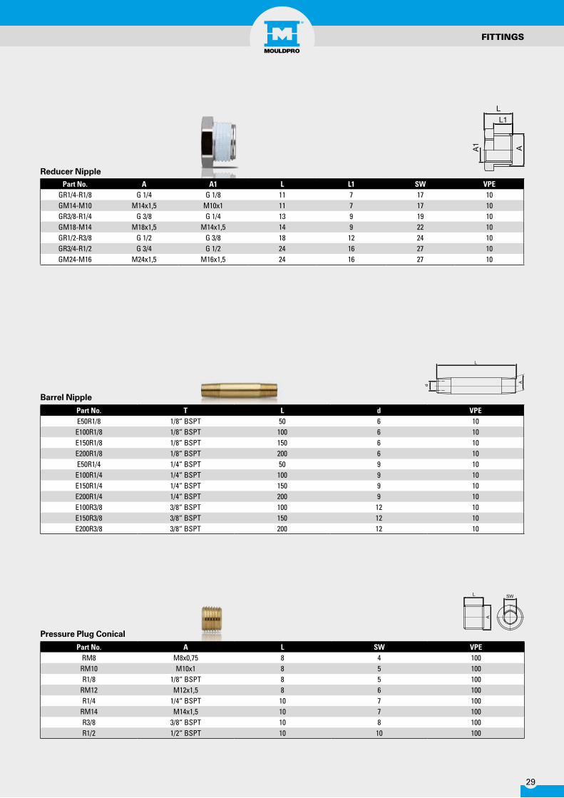
Part No. T L d VPEE50R1/8 1/8“ BSPT 50 6 10
E100R1/8 1/8“ BSPT 100 6 10E150R1/8 1/8“ BSPT 150 6 10E200R1/8 1/8“ BSPT 200 6 10E50R1/4 1/4“ BSPT 50 9 10
E100R1/4 1/4“ BSPT 100 9 10E150R1/4 1/4“ BSPT 150 9 10E200R1/4 1/4“ BSPT 200 9 10E100R3/8 3/8“ BSPT 100 12 10E150R3/8 3/8“ BSPT 150 12 10E200R3/8 3/8“ BSPT 200 12 10
FITTINgS
Part No. A A1 L L1 SW VPEGR1/4-R1/8 G 1/4 G 1/8 11 7 17 10GM14-M10 M14x1,5 M10x1 11 7 17 10GR3/8-R1/4 G 3/8 G 1/4 13 9 19 10GM18-M14 M18x1,5 M14x1,5 14 9 22 10GR1/2-R3/8 G 1/2 G 3/8 18 12 24 10GR3/4-R1/2 G 3/4 G 1/2 24 16 27 10GM24-M16 M24x1,5 M16x1,5 24 16 27 10
Part No. A L SW VPERM8 M8x0,75 8 4 100RM10 M10x1 8 5 100R1/8 1/8“ BSPT 8 5 100
RM12 M12x1,5 8 6 100R1/4 1/4“ BSPT 10 7 100
RM14 M14x1,5 10 7 100R3/8 3/8“ BSPT 10 8 100R1/2 1/2“ BSPT 10 10 100
Pressure Plug Conical
Reducer Nipple
Barrel Nipple

30
Part No. A D L L1 VPES6 M3 6 11,5 3,5 100S8 M4 8 11,5 3,5 100
S10-1 M6 10 14 4 100S12 M6 12 14 4 100S16 M8 16 16 4 100
FITTINgS
Part No. A D L L1 SW VPEDM10 M10x1 14 11 8 5 25DR1/8 G 1/8 14 11 8 5 25DM12 M12x1,5 17 15 12 6 25DR1/4 G 1/4 18 15 12 6 25DM14 M14x1,5 19 15 12 6 25DR3/8 G 3/8 22 15 12 8 25DR1/2 G 1/2 26 18 14 10 25
Pressure Plug Cylindrical
Part No. A L SW VPERM8C M8x0,75 8 4 100
RM10C M10x1 8 5 100R1/8C 1/8“ BSP 8 5 100
RM12C M12x1,5 8 6 100R1/4C 1/4“ BSP 10 7 100
RM14C M14x1,5 10 7 100R3/8C 3/8“ BSP 10 8 100R1/2C 1/2“ BSP 10 10 100
Hex Plug
Channel Plug
Part No. d1 LengthKN105-6 6 10KN105-8 8 10
KN105-10 10 10KN105-12 11 10
DescriptionMaterial: BrassO-ring Viton
Channel Plug

31
BALL VALVES
Part No. SizeVLMF04 1/4"VLMF06 3/8"VLMF08 1/2"VLMF12 3/4"VLMF16 1"
DescriptionMaximum working pressure 32 BarWorking temperature -20°C to + 150°C
Part No. SizeVM04 1/4"VM06 3/8"VM08 1/2"
DescriptionMaximum working pressure 32 BarWorking temperature -20°C to + 150°C
Male/female ball valve
Female/female ball valve
Mini ball valve
Part No. SizeVL04 1/4"VL06 3/8"VL08 1/2"VL12 3/4"VL16 1"VL20 1-1/4"VL24 1-1/2"
DescriptionMaximum working pressure 40 BarWorking temperature -20°C to + 100°C

32
MANIFOLDS
Part No. Colour Ports A (BSPP) A2 (BSPP) L2 L3 L1 d1 d2 N LIM3-4-C-4-1/4-P-R 4 1/4” 3/4” 57,2 38,1 38,1 4,5 8 31 190,5IM3-4-C-4-1/4-P-B 4 1/4” 3/4” 57,2 38,1 38,1 4,5 8 31 190,5IM3-6-C-6-1/4-P-R 6 1/4” 3/4” 57,2 38,1 38,1 4,5 8 31 266,7IM3-6-C-6-1/4-P-B 6 1/4” 3/4” 57,2 38,1 38,1 4,5 8 31 266,7IM3-8-C-8-1/4-P-R 8 1/4” 3/4” 57,2 38,1 38,1 4,5 8 31 342,9IM3-8-C-8-1/4-P-B 8 1/4” 3/4” 57,2 38,1 38,1 4,5 8 31 342,9
DescriptionRugged Low Cost DesignAnodized Aluminium in Blue or Red for easy identification of Flow and ReturnQuick Mould ChangeEliminates Piping ErrorsShorter Hose Lengths minimise pressure drops and reduces clutterMaximum Unresticted Flow Rates PossibleStandard or Custom Designs Available
Part No. Colour Ports A (BSPP) A2 (BSPP) L2 L3 L1 d1 d2 N LIM4-6-C-4-1/4-P-R 4 1/4" 1" 63,5 38,1 38,1 7 10,5 40,6 190,5IM4-6-C-4-1/4-P-B 4 1/4" 1" 63,5 38,1 38,1 7 10,5 40,6 190,5IM4-6-C-4-3/8-P-R 4 3/8" 1" 63,5 38,1 50,8 7 10,5 40,6 228,6IM4-6-C-4-3/8-P-B 4 3/8" 1" 63,5 38,1 50,8 7 10,5 40,6 228,6IM4-9-C-6-1/4-P-R 6 1/4" 1" 63,5 38,1 38,1 7 10,5 40,6 266,7IM4-9-C-6-1/4-P-B 6 1/4" 1" 63,5 38,1 38,1 7 10,5 40,6 266,7IM4-9-C-6-3/8-P-R 6 3/8" 1" 63,5 38,1 50,8 7 10,5 40,6 330,2IM4-9-C-6-3/8-P-B 6 3/8" 1" 63,5 38,1 50,8 7 10,5 40,6 330,2IM4-11-C-8-1/4-P-R 8 1/4" 1" 63,5 38,1 38,1 7 10,5 40,6 342,9IM4-11-C-8-1/4-P-B 8 1/4" 1" 63,5 38,1 38,1 7 10,5 40,6 342,9IM4-11-C-8-3/8-P-R 8 3/8" 1" 63,5 38,1 50,8 7 10,5 40,6 431,8IM4-11-C-8-3/8-P-B 8 3/8" 1" 63,5 38,1 50,8 7 10,5 40,6 431,8
DescriptionRugged Low Cost DesignAnodized Aluminium in Blue or Red for easy identification of Flow and ReturnQuick Mould ChangeEliminates Piping ErrorsShorter Hose Lengths minimise pressure drops and reduces clutterMaximum Unresticted Flow Rates PossibleStandard or Custom Designs Available
3/4” Inline anodized Manifold
1” Inline anodized Manifold
L
A
L2L2
L1
A2 A2
L3
d2
d1
N
L
A
L2L2
L1
A2 A2
L3
d2
d1
N

33
MANIFOLDS
1-1/2” Inline anodized Manifold
Part No. Colour Ports A (BSPP) A2 (BSPP) L2 L3 L1 d1 d2 N LIM6-10-C-4-1/2-P-R 4 1/2" 1-1/2" 76,2 50,8 50,8 7 10,5 57 254,0IM6-10-C-4-1/2-P-B 4 1/2" 1-1/2" 76,2 50,8 50,8 7 10,5 57 254,0IM6-14-C-6-1/2-P-R 6 1/2" 1-1/2" 76,2 50,8 50,8 7 10,5 57 355,6IM6-14-C-6-1/2-P-B 6 1/2" 1-1/2" 76,2 50,8 50,8 7 10,5 57 355,6IM6-18-C-8-1/2-P-R 8 1/2" 1-1/2" 76,2 50,8 50,8 7 10,5 57 457,2IM6-18-C-8-1/2-P-B 8 1/2" 1-1/2" 76,2 50,8 50,8 7 10,5 57 457,2
DescriptionRugged Low Cost DesignAnodized Aluminium in Blue or Red for easy identification of Flow and ReturnQuick Mould ChangeEliminates Piping ErrorsShorter Hose Lengths minimise pressure drops and reduces clutterMaximum Unresticted Flow Rates PossibleStandard or Custom Designs Available
L
A
L2L2
L1
A2 A2
L3
d2
d1
N
Part No. A D L L1 SW VPEDR3/4 G3/4" 32 21 16 12 1DR1 G1" 40 22,5 16 17 1
DR1-1/2 G1-1/2" 55 22,5 16 24 1
Blanking Plugs

34
FLOW REgULATOR/INDICATOR
Waterflow Regulator
Use: The CFV impeller flow indicators are generally used to monitor the correct flowing and circulation of a fluid into a pipeline. They are ideal for cooling and heating circuits, water treatment, and plastics processing equipment.
Note:Flow rates refer to a vertical mounting with fluid inlet upwards.
Specifications: Body Nickle-plated brassImpeller Red HostaformGlass PirexSeals NBRMax temperature 90°C
Part No.Flow Rate H²O LPM
Length Ø mm Thread AF Max Pressure(bar)Min Max
CFV1BN 1 10 59 25 1/4” 19 10CFV2BN 2 20 71 30 3/8” 24 8CFV3BN 3 30 71 30 1/2” 24 8CFV4BN 4 40 106 47 3/4” 40 5CFV5BN 6 60 106 47 1” 40 5
Flow Indicator
Part No. Water flow Main Connections inlet / oulet Max.Temp. Zones Zone Connection Dimension A
MPR02R 0-18 lpm R 3/4" 95ºC 2 R 3/8" 125MPR04R 0-18 lpm R 3/4" 95ºC 4 R 3/8" 230MPR06R 0-18 lpm R 3/4" 95ºC 6 R 3/8" 335MPR08R 0-18 lpm R 3/4" 95ºC 8 R 3/8" 440MPR10R 0-18 lpm R 3/4" 95ºC 10 R 3/8" 545MPR12R 0-18 lpm R 3/4" 95ºC 12 R 3/8" 635
DescriptionWater flow regulators are ideal for regulating the flow rate of water passing through them as well as the water outlet temperature.The high quality construction and design make the unit one of the most competitive.
Technical characteristics that makes the flow regulator different from its competitors:
• The tube is made of Polyamide (standard).• Inferior and superior bodies are made of PA 6 with 30% fibre glass.• Brass regulating taps.• Thermometers (standard).• Stainless steel interior tie-rods.• Vitrilic rubber o-rings (hardness: 70 SHA).• Brass inlet and outlet valves inserted in the body.
54R3/
4R
3/4
OU
TLET
INLE
T
R3/
4R
3/4
OU
TLET
INLE
T
A
37

35
DE-SCALINg
Part No. Tank Capacity Flow Rate Reverse system Fittings HPDP15M 15 l. 48 l/min. Manual 1/2" 0,2DP15A 15 l. 40 l/min Automatic 1/2" 0,17DP30M 24 l. 90 l/min. Manual 1/2" 0,45DP30A 24 l. 91 l/min. Automatic 1/2" 0,45
DescriptionUse for clearing blocked or badly corroded heating and cooling circuits on Injection Moulding Machines and Moulds. Even when not blocked a relatively thin layer of scale or corrosion can act as an insulator and have a huge impact on the efficiency of your circuit. Simply fill up the pump with the descaling fluid, connect the pump to the inlet and outlet of the circuit and turn on the pump. Regular reversal of flow direction, either manual or automatic, speeds up operation and assists in dislodging any solid matter present in pipework and cooling circuits.
By using the pump together with the recommended range of descaling fluids to remove both rust and limescale deposits. The descaling fluid contains a colour change indicator to monitor performance; the translucent tank means that the user can see when the red colour runs clear and is no longer effective. Use the neutralising fluid to create a pH neutral fluid which can be easily disposed of.
• Compact and Portable • Safe and Easy to Use • Maintenance Free • Integral tank for safety and convenience • Translucent Tank to monitor cleaning fluid performance • Descaling fluid safely contained at all time • Flow reversing (manual or automatic) • Full range of cleaning products available
Part No. KG Type Description
RL10 10 Remover Liquid Descaling solution, powerful reaction for heating and cooling systems in: Copper and Steel
RL10P 10 Remover Plus Liquid Descaling solution, (non-fuming), degreasing action for heating and cooling systems in: Copper and Steel
RP10 10 Remover plus Powder Descaling powder(corrosion inhibitor-non fuming) for heating ad cooling systems in: Copper - Steel - Stainless Steel - Aluminium - Brass - Tin - Light Alloys
NP10 10 NeutralizerNeutralizing powder to remove residual activity. Post-descaling treatment in heating
and cooling systems. Also suitable to neutralize used descaling agents, allowing discharge to drain
De-scaling PumpWith flow reverser Automatic Reverser Manual Reverser
De-scaling Solution

36
Pressure test unit
PTFE Tape
Thread Locker
Part No. Pressure (BAR) WeightMP-60 0-60 5,5 kg.
DescriptionPressure test unit - for easy leakage test of Mould circuitsSupplied with connecting hose and water tank
Part No. Size LengthTEF 12 mm. 12 m
DescriptionExcellent for sealing all thread sizesTemperature range: up to 230°C
Part No. Size Max Thread Temperature range77 50 ml. < M80 -50°C - +150°C
DescriptionAnaerobic Thread locker for permanent sealing of metal threaded fittings Single component, liquid adhesive that cures hard in the absence of air or oxygen Maximum Thread Size: M80 Disassembly strength: HighTemperature range: -50°C - +150°CBreakaway torque: 32 NmPack sizes: 50ml
TEST UNIT/SEALANTS

37
Pipe Sealant
Pipe Sealant
Adhesive
Part No. Size Max Thread Temperature range542 50 ml. < 3/4" -50°C - +150°C
DescriptionAnaerobic thread sealant for fine metal threaded fittings, especially hydraulic pipes Single component, liquid adhesive that cures hard in the absence of air or oxygen Maximum pipe size: 3/4”Disassembly strength: Medium Temperature range: -50°C - +150°C Breakaway torque: 15 NmPack sizes: 50ml
Part No. Size Max Thread Temperature range577 50 ml. < 3" -50°C - +150°C
577-2 250 ml. < 3" -50°C - +150°C
DescriptionGeneral purpose anaerobic thread sealant for all coarse metal threadsSingle component, liquid adhesive that cures hard in the absence of air or oxygenMaximum Pipe Size: 3”Disassembly strength: MediumTemperature range: -50°C - +150°CBreakaway torque: 11 NmPack sizes: 50ml, 250ml
Part No. Size Temperature range401 20 gr. 80 ° C
DescriptionInstant general purpose adhesive - universal, low viscosityFixture time: 3 – 10 sec.Colour: transparent Temperature range: -40 °C to +80 °CPack sizes: 20g
SEALANT AND ADHESIVE

38
02.conSuMablES
Mould Sprays
Nano Mould Coating
Purging Compound
39
MOULD SPRAyS
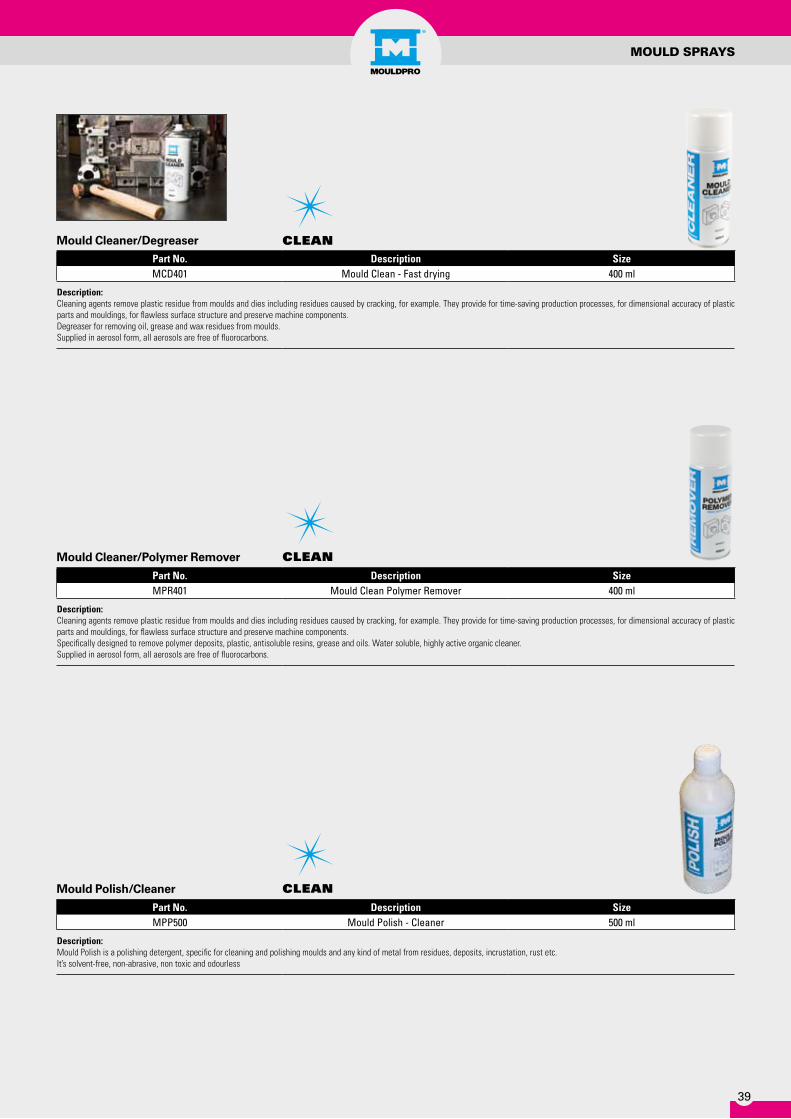
Part No. Description SizeMCD401 Mould Clean - Fast drying 400 ml
Description: Cleaning agents remove plastic residue from moulds and dies including residues caused by cracking, for example. They provide for time-saving production processes, for dimensional accuracy of plastic parts and mouldings, for flawless surface structure and preserve machine components.Degreaser for removing oil, grease and wax residues from moulds.Supplied in aerosol form, all aerosols are free of fluorocarbons.
Mould Cleaner/Degreaser clEan
clEan
clEan
Part No. Description SizeMPR401 Mould Clean Polymer Remover 400 ml
Description: Cleaning agents remove plastic residue from moulds and dies including residues caused by cracking, for example. They provide for time-saving production processes, for dimensional accuracy of plastic parts and mouldings, for flawless surface structure and preserve machine components.Specifically designed to remove polymer deposits, plastic, antisoluble resins, grease and oils. Water soluble, highly active organic cleaner.Supplied in aerosol form, all aerosols are free of fluorocarbons.
Part No. Description SizeMPP500 Mould Polish - Cleaner 500 ml
Description: Mould Polish is a polishing detergent, specific for cleaning and polishing moulds and any kind of metal from residues, deposits, incrustation, rust etc. It’s solvent-free, non-abrasive, non toxic and odourless
Mould Cleaner/Polymer Remover
Mould Polish/Cleaner

40
MOULD SPRAyS
Description: Withstands temperatures up to 540°C • Hydrophobic and oleophobic, yet vapor permeable • Transparent film thickness of 100-200nm • Low coefficient of friction • Designed to resist most common chemical cleaners • Offers corrosion protection • Can be used on all tool steel and aluminum surfaces • Can be used to release all thermoplastic, thermoset, and rubber materials • Non-Toxic
Notes:: Each kit comes standard with:• Pre-mixed Coating in dropper bottle• Bottle of remover• 2-micro fiber applicator swabs• 2-applicator cloth
Release Plastic Parts from Moulds for up to 500.000 CyclesReduce cycle times Improve fill and packImprove surface finish by elminating resin drag and stretch
Standard TypePart No. SizeHC-5ml 5ml Kit
FDA ApprovedPart No. SizeHCF-5ml 5ml Kit
NanoMoldcoating®
rElEaSE
Part No. Description SizeMRN401 Mould Release Silicone free 400 ml
Description: Universal Release Agent on a base of Synthetic Oils.A high quality proven release agent that ensures trouble freemoulding, saves time, shortens cycles times, reduces scrap and is gentle on dies and moulds.Suitable for thermoplastic or thermoset moulding.
Mould Release, Silicon Free rElEaSE

41
Part No. Description SizeMLF500 Ejector Pin Grease 0,5 kg
Description:Non-soiling lubricants that keep moving parts running smoothly and prevent damage due to breakage and seizing. For Slides and Ejector Pins. Thin-film lubrication, Food Grade, long term action, good protection from corrosion.Operating Temperature - upto 270°C
Food Grade Lubricant
Part No. Description SizeMEL401 Ejector Pin Lubricant 400 ml
Description:Heavy duty clear lubricant for ejector pins and other close tolerance mould parts. Extremely tenacious, clear non-staining film which withstands extreme pressure and friction. Operational to 120°C Supplied in Aerosol cans
Ejector Pin Lubricant
MOULDSPRAyS
Part No. Description SizeMPG401 Mould Protect Green 400 mlMPG501 Mould Protect Green 5 litre
Description: Anticorrosion agents provide dismantled die, moulds and parts with long-term protection against corrosions. This ensures that your mould is always ready for use, maintaining value and efficiency.It is not neccesary to remove the protective film prior to use. This agent does not creep.
Mould Protect, Green ProtEct
ProtEct
Part No. Description SizeMPW401 Mould Protect Clear 400 mlMPW501 Mould Protect Clear 5 litre
Description: Anticorrosion agents provide dismantled die, moulds and parts with long-term protection against corrosions. This ensures that your mould is always ready for use, maintaining value and efficiency.It is not neccesary to remove the protective film prior to use. This agent does not creep.
Mould Protect, Clear
lubrIcatE
lubrIcatE

42
PURgINg COMPOUND
Inje
ctio
n M
ould
ing
Blo
w M
ould
ing
Pass
filte
r
Hot
runn
er s
uita
ble
NSF
regi
stre
red
Poly
olefi
ns
PS SAN
, AB
S, A
SA
PVC
PTFE
, PVD
F
PMM
A
POM
PA6,
PA
66, P
A61
0, P
A11
, PA
12
PC, P
C/A
BS
PET,
PB
T
PPO
, PEE
K, P
PS, P
ES, P
SU, L
CP
CA, C
AB
, CP
TPU
, TPE
Tem
pera
ture
rang
e >3
00°C
Tem
pera
ture
rang
e 18
0-30
0°C
Part No. SizeMC200 MasterClean 20 Kg. • • • • • • • • • • • • •MC100 MasterClean 20 Kg. • • • • • • • •MP1X MultiPurge 1 kg. • • • • • • • • • • • • • • • • • • •MP5X MultiPurge 5 Kg. • • • • • • • • • • • • • • • • • • •MP10X MultiPurge 10 Kg. • • • • • • • • • • • • • • • • • • •MP20X MultiPurge 20 Kg. • • • • • • • • • • • • • • • • • • •
Description: Ready to use CompoundsSafe and fast cleaning of screws, cylinders and nozzles.
• Highly recommended Medium recommended Suitable
Purging Compound
A range of purging compounds suitable for Injection Moulding / Blow Moulding and Extrusion – see the table below to choose the correct product for your application.
MasterCleanReady-to-use granular purging compound for the cleaning of screws, cylinders, machine nozzles and hot runners.
Features• Quick Colour Changes • Quick Material Changes • Effective removal of Carbon (Black Spots)• Effective Shut Down Medium for Heat
Sensitive Materials
Benefits• Easy to Use – Follow the simple Instruc-
tions• Reduced Downtime – Fast and Effective
Operation means faster changeovers• Non Abrasive – Our purging compound
is a high grade polymer with additives containing no abrasives
• Clean – A high quality product that gene-rates No Smoke, Vapour or Odours during operation.
• Economical – Only a small amount of pur-ging compound is required this combined with Fast and Effective Operation means lower downtime and increases productivity.
• Food Grade – NSF Approved
MultiPurge *NEW*A New Purging Concentrate which can be mixed with virgin material making it suitable for use with ALL types of polymers (olefins and styrene’s).
Multipurge is an extremely economical pro-duct which is mixed at a low percentage with the base material and can then be proces-sed through the machine using the normal parameters.

43
03.HEatErS & tEMPEraturE control
Nozzle Heaters
Thermocouples
Infrared Thermometer
44
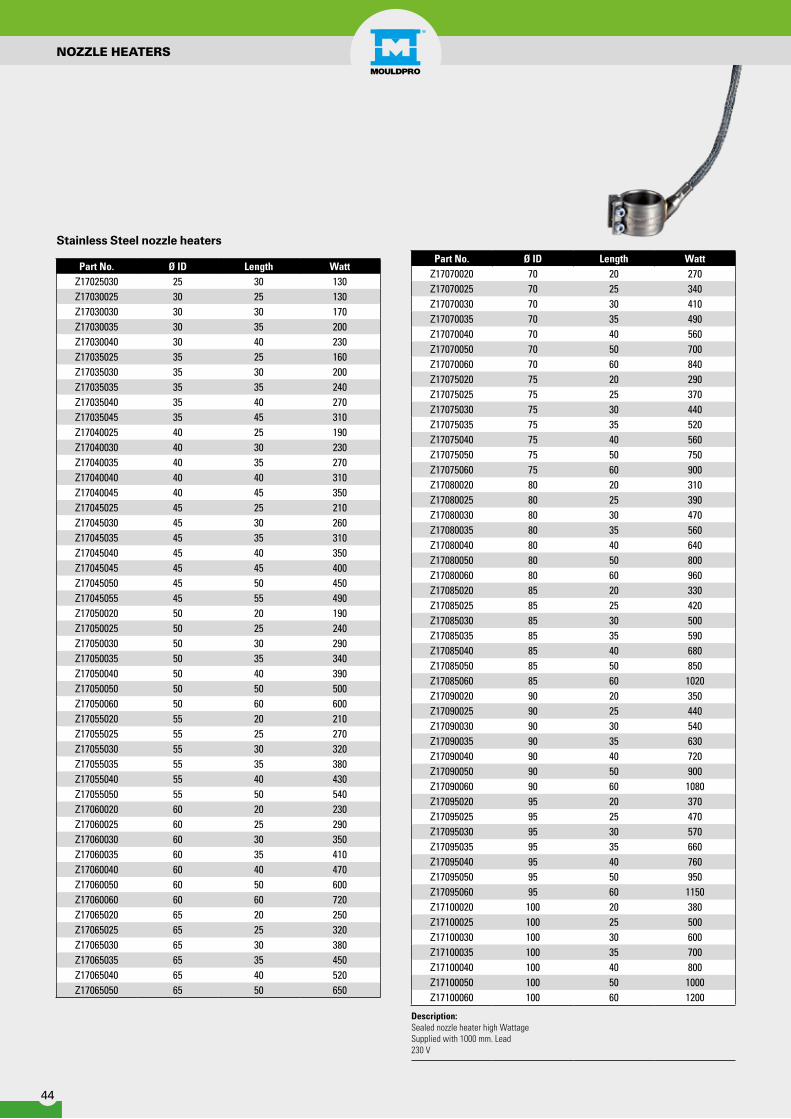
Part No. Ø ID Length WattZ17025030 25 30 130Z17030025 30 25 130Z17030030 30 30 170Z17030035 30 35 200Z17030040 30 40 230Z17035025 35 25 160Z17035030 35 30 200Z17035035 35 35 240Z17035040 35 40 270Z17035045 35 45 310Z17040025 40 25 190Z17040030 40 30 230Z17040035 40 35 270Z17040040 40 40 310Z17040045 40 45 350Z17045025 45 25 210Z17045030 45 30 260Z17045035 45 35 310Z17045040 45 40 350Z17045045 45 45 400Z17045050 45 50 450Z17045055 45 55 490Z17050020 50 20 190Z17050025 50 25 240Z17050030 50 30 290Z17050035 50 35 340Z17050040 50 40 390Z17050050 50 50 500Z17050060 50 60 600Z17055020 55 20 210Z17055025 55 25 270Z17055030 55 30 320Z17055035 55 35 380Z17055040 55 40 430Z17055050 55 50 540Z17060020 60 20 230Z17060025 60 25 290Z17060030 60 30 350Z17060035 60 35 410Z17060040 60 40 470Z17060050 60 50 600Z17060060 60 60 720Z17065020 65 20 250Z17065025 65 25 320Z17065030 65 30 380Z17065035 65 35 450Z17065040 65 40 520Z17065050 65 50 650
Part No. Ø ID Length WattZ17070020 70 20 270Z17070025 70 25 340Z17070030 70 30 410Z17070035 70 35 490Z17070040 70 40 560Z17070050 70 50 700Z17070060 70 60 840Z17075020 75 20 290Z17075025 75 25 370Z17075030 75 30 440Z17075035 75 35 520Z17075040 75 40 560Z17075050 75 50 750Z17075060 75 60 900Z17080020 80 20 310Z17080025 80 25 390Z17080030 80 30 470Z17080035 80 35 560Z17080040 80 40 640Z17080050 80 50 800Z17080060 80 60 960Z17085020 85 20 330Z17085025 85 25 420Z17085030 85 30 500Z17085035 85 35 590Z17085040 85 40 680Z17085050 85 50 850Z17085060 85 60 1020Z17090020 90 20 350Z17090025 90 25 440Z17090030 90 30 540Z17090035 90 35 630Z17090040 90 40 720Z17090050 90 50 900Z17090060 90 60 1080Z17095020 95 20 370Z17095025 95 25 470Z17095030 95 30 570Z17095035 95 35 660Z17095040 95 40 760Z17095050 95 50 950Z17095060 95 60 1150Z17100020 100 20 380Z17100025 100 25 500Z17100030 100 30 600Z17100035 100 35 700Z17100040 100 40 800Z17100050 100 50 1000Z17100060 100 60 1200
Description:Sealed nozzle heater high WattageSupplied with 1000 mm. Lead230 V
Stainless Steel nozzle heaters
NOzzLE HEATERS
45
NOzzLE HEATERS
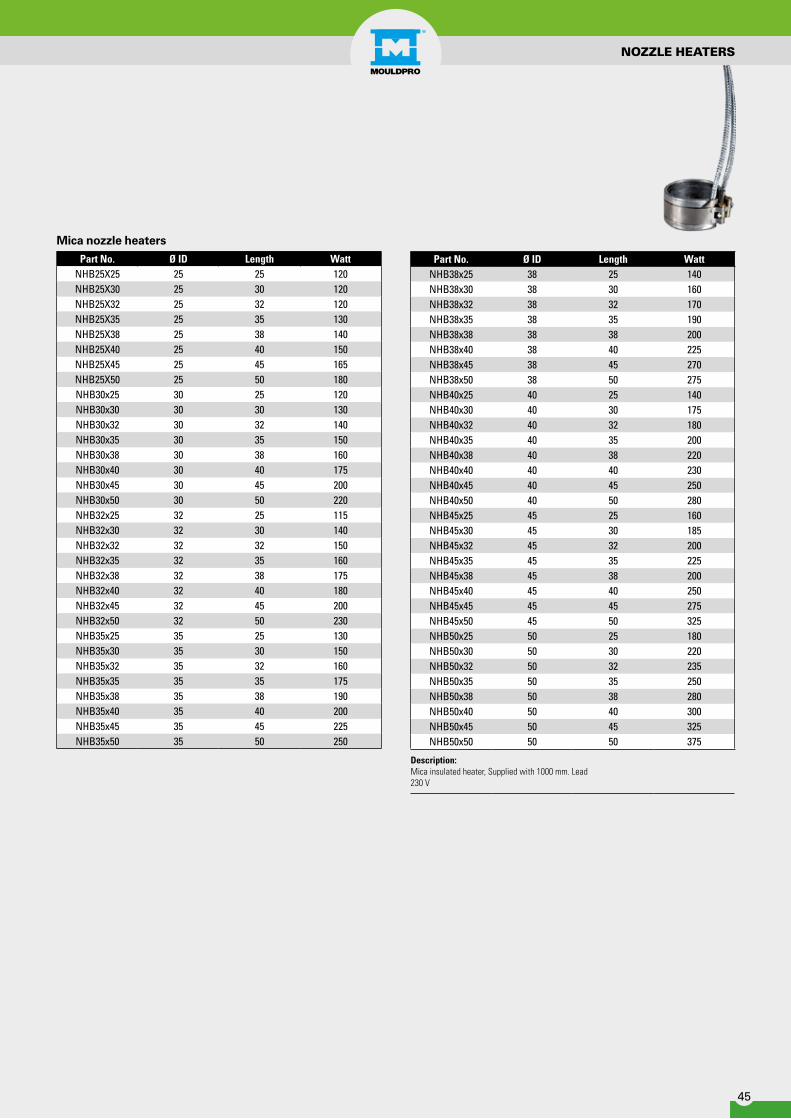
Part No. Ø ID Length WattNHB25X25 25 25 120NHB25X30 25 30 120NHB25X32 25 32 120NHB25X35 25 35 130NHB25X38 25 38 140NHB25X40 25 40 150NHB25X45 25 45 165NHB25X50 25 50 180NHB30x25 30 25 120NHB30x30 30 30 130NHB30x32 30 32 140NHB30x35 30 35 150NHB30x38 30 38 160NHB30x40 30 40 175NHB30x45 30 45 200NHB30x50 30 50 220NHB32x25 32 25 115NHB32x30 32 30 140NHB32x32 32 32 150NHB32x35 32 35 160NHB32x38 32 38 175NHB32x40 32 40 180NHB32x45 32 45 200NHB32x50 32 50 230NHB35x25 35 25 130NHB35x30 35 30 150NHB35x32 35 32 160NHB35x35 35 35 175NHB35x38 35 38 190NHB35x40 35 40 200NHB35x45 35 45 225NHB35x50 35 50 250
Mica nozzle heaters
Part No. Ø ID Length WattNHB38x25 38 25 140NHB38x30 38 30 160NHB38x32 38 32 170NHB38x35 38 35 190NHB38x38 38 38 200NHB38x40 38 40 225NHB38x45 38 45 270NHB38x50 38 50 275NHB40x25 40 25 140NHB40x30 40 30 175NHB40x32 40 32 180NHB40x35 40 35 200NHB40x38 40 38 220NHB40x40 40 40 230NHB40x45 40 45 250NHB40x50 40 50 280NHB45x25 45 25 160NHB45x30 45 30 185NHB45x32 45 32 200NHB45x35 45 35 225NHB45x38 45 38 200NHB45x40 45 40 250NHB45x45 45 45 275NHB45x50 45 50 325NHB50x25 50 25 180NHB50x30 50 30 220NHB50x32 50 32 235NHB50x35 50 35 250NHB50x38 50 38 280NHB50x40 50 40 300NHB50x45 50 45 325NHB50x50 50 50 375
Description:Mica insulated heater, Supplied with 1000 mm. Lead230 V
46
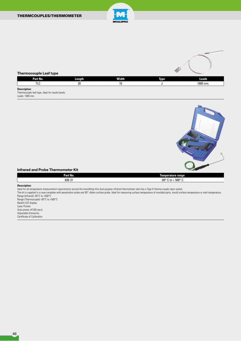
Part No. Length Width Type LeadsTLC 20 10 J 1000 mm.
Description: Thermocouple leaf type, ideal for nozzle bands. Leads: 1000 mm.
Part No. Temperature range826-31 -60° C to + 500° C
Description: Ideal for all temperature measurement requirements around the mouldshop this dual purpose infrared thermometer also has a Type K thermo-couple input socket.The kit is supplied in a case complete with penetration probe and 90° ribbon surface probe. Ideal for measuring surface temperature of moulded parts, mould surface temperature or melt temperature.Range (Infrared) -60°C to +500°CRange (Thermocouple) -60°C to +500°CBacklit LCD displayLaser PointerAuto power off (60 secs)Adjustable EmissivityCertificate of Calibration
Thermocouple Leaf type
Infrared and Probe Thermometer Kit
THERMCOUPLES/THERMOMETER
47
04.MatErIal HandlIng
Loader Hoses
Hopper Magnets
Material Scoops

48
LOADER HOSES
Part No. Internal Diameter Ø (mm) UOMPUP38 38mm 30mPUP40 40mm 30mPUP45 45mm 30mPUP50 50mm 30mPUP60 60mm 30m
Description: Anti-Static Polyurethane hose reinforced with rigid PVC spiral helix and copper wireInside surface perfectly smooth, outside corrugatedExcellent flexibilityHigh abrasion resistanceOperating temperature -20ºC to +80ºC30m Coil
Part No. Internal Diameter Ø (mm) UOMPURH38 38mm 10mPURH40 40mm 10mPURH45 45mm 10mPURH50 50mm 10mPURH60 60mm 10m
Description: Polyurethane hose reinforced with a copper covered steel helixVery high resistance to abrasionsExcellent flexibilitySmooth Bore Operating temperature -40ºC to +80ºC10m Coil
PU Hose/PVC Helix
PU Hose/Steel Helix
Part No. Internal Diameter Ø (mm) UOMPAPVC19 19mm 30mPAPVC25 25mm 30mPAPVC31 31mm 30mPAPVC38 38mm 30mPAPVC50 50mm 30mPAPVC64 64mm 30mPAPVC75 75mm 30m
Description: Clear PVC Hose with a steel spiral helixExcellent FlexibilityInside & Outside SmoothOperating Temperature -10ºC to +60ºC30m Coil
PVC Hose

49
SILICON DRyER HOSE / WIRE CLIP SCREW
Part No. Hose I/D (mm) UOMSIL132 32mm 4mSIL138 38mm 4mSIL141 41mm 4mSIL151 51mm 4mSIL160 60mm 4mSIL170 70mm 4m
Description: Coated glass fabric - Single PlyOperating Temperature -60ºC to +250ºC4 Metre Length
Silicon Dryer Hose
Part No. Size range mm.03030200 33-3703030218 35,5-4003030226 38,5-4303030234 41-4603030242 43,5-4903030250 46,5-5303030269 50,5-5603030277 53,5-6003030285 56,5-6403030293 60-6803030306 64-72
Description: Wire: Steel wire B-UNI 3823Screw: 6.6 grade steel Cr3 zinc-plated
This clip was specially designed for use with hoses incorporating an outer helix.It is generally used when installing ventilation ducting.The double-wire construction of this clip means that it sits comfortably on either side of the helixand can then be clamped down firmly thanks to the screw-tightening system.
Wire Clip with ScrewIdeal for Loader hoses with outer helix.

50
HOPPER MAgNET / SCOOP
Part No. Size2885 1.9ltr
Description: 1.9Ltr Material ScoopIdeal for scooping granules and tipping into material hoppers
Material Scoop
Part No. Size DiameterD150 150mm.D200 200mm.D250 250mm.D300 300mm.
Description: Separation Magnets, Stainless Steel encased. Place direct in the Hopper to separate metal from polymers and avoid damage of nozzle and hotrunners etc.
Hopper magnets
51
05.End oF arM toolIng
Flat Vacuum Cups
Bellow Vacuum Cups

52
Vacuum Cup Fitting Retaining Ring Complete
Part No. ØD H H1 Part No. ØA B C E Part No. ØN ØO P Part No.F20S
0,5 mm 22 8 17,5
F250 16 14,5 M5 G1/8" R.011 14 9,7 1,8
FC20SF20N FC20NF25S
1,0 mm 28 9 19FC25S
F25N FC25NF30S
1,5mm 32 10 19FC30S
F30N FC30NF40S
2,0 mm 42 13 21 F251 21 15G1/8" Ø15
R.012 20 13 2,5FC40S
F40N FC40NF50S
3,0 mm 53 17,5 27 F252 28 18 R.013 26 19 3,2FC50S
F50N FC50N
Material Selection:Silicone = SNBR = NEx. F20S (Silicone)Ex. F20N (NBR)
Flat Vacuum Cups Ø 22 – 52 mmWith cleats for better stability
H1
AB
EC
N
O
P
D
H
Vacuum Cup Fitting Complete
Part No. ØD Ø D1 H H1 H2 Part no. ØA B C Ø E Ø F SW Part No.F75S
2,0 mm 75 G1/8" 14 20 17 F138 60 12 G1/8" 15 50 14FC75S
F75N FC75NF110S
5,0 mm 110G1/2"
19 2632
F139 85 13 G1/2" 30 74 30FC110S
F110N FC110NF150S
5,0 mm 150 25 32 F140 120 14 G1/2" 30 74 30FC150S
F150N FC150N
Material Selection:Silicone = SNBR = NEx. F75S (Silicone)Ex. F75N (NBR)
Flat Vacuum Cups Ø 75 - Ø 150For irregular surfaces and higher lifting forces
EFA
B
C
D1
H1
D
H
D
FLAT VACUUM CUPS
53
BELLOW VACUUM CUPS
Vacuum Cup Fitting Retaining Ring Complete
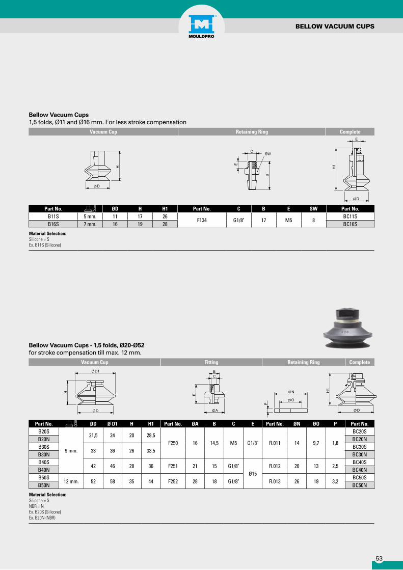
Part No. ØD Ø D1 H H1 Part No. ØA B C E Part No. ØN ØO P Part No.B20S
9 mm.
21,5 24 20 28,5F250 16 14,5 M5 G1/8" R.011 14 9,7 1,8
BC20SB20N BC20NB30S
33 36 26 33,5BC30S
B30N BC30NB40S
42 46 28 36 F251 21 15 G1/8"Ø15
R.012 20 13 2,5BC40S
B40N BC40NB50S
12 mm. 52 58 35 44 F252 28 18 G1/8" R.013 26 19 3,2BC50S
B50N BC50N
Material Selection:Silicone = SNBR = NEx. B20S (Silicone) Ex. B20N (NBR)
Bellow Vacuum Cups - 1,5 folds, Ø20-Ø52for stroke compensation till max. 12 mm.
N
O
P
A
B
EC
D
H1
D
H
D1
Vacuum Cup Retaining Ring Complete
Part No. ØD H H1 Part No. C B E SW Part No.B11S 5 mm. 11 17 26
F134 G1/8" 17 M5 8BC11S
B16S 7 mm. 16 19 28 BC16S
Material Selection:Silicone = SEx. B11S (Silicone)
Bellow Vacuum Cups1,5 folds, Ø11 and Ø16 mm. For less stroke compensation
D
H
C
E
B
SW
E
H1
D
54
BELLOW VACUUM CUPS
Vacuum Cup Retaining Ring Complete
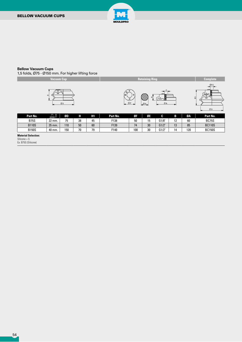
Part No. ØD H H1 Part No. ØF ØE C B ØA Part No.B75S 22 mm. 75 38 45 F138 50 15 G1/8" 12 60 BC75SB110S 35 mm. 110 50 60 F139 74 30 G1/2" 13 85 BC110SB150S 40 mm. 150 70 79 F140 100 30 G1/2" 14 120 BC150S
Material Selection:Silicone = SEx. B75S (Silicone)
Bellow Vacuum Cups1,5 folds, Ø75 - Ø150 mm. For higher lifting force
D
H1
D1
E A
B
C
FD
H

55
06.End oF barrEl
Screw Tip Assemblies
Tip Spanner
Replacement Nozzle Tips
Hot Tip Sprue Cleaner

56
Part No. DiameterSTA-18 18mmSTA-20 20mmSTA-22 22mmSTA-25 25mmSTA-27 27mmSTA-28 28mmSTA-30 30mmSTA-32 32mmSTA-33 33mmSTA-35 35mmSTA-37 37mmSTA-38 38mmSTA-40 40mmSTA-42 42mmSTA-43 43mmSTA-45 45mmSTA-47 47mmSTA-48 48mmSTA-50 50mmSTA-52 52mmSTA-55 55mmSTA-60 60mmSTA-62 62mmSTA-65 65mm
Screw Tip Assembly
SCREW TIPS/SPANNER
Part No. DiameterSTA-67 67mmSTA-70 70mmSTA-72 72mmSTA-75 75mmSTA-78 78mmSTA-80 80mmSTA-85 85mmSTA-90 90mmSTA-95 95mm
STA-100 100mmSTA-105 105mmSTA-110 110mmSTA-120 120mmSTA-125 125mmSTA-130 130mmSTA-135 135mmSTA-140 140mmSTA-150 150mmSTA-155 155mmSTA-160 160mmSTA-170 170mmSTA-180 180mmSTA-190 190mmSTA-200 200mm
Description: For all popular makes of moulding machineComplete nitrided screw tip assembly including Screw Tip, Check Ring and Pressure Ring.Please advise machine make / model / tonnage and screw size when ordering
Part No. Screw tip Size123894 Max 75 mm
Description: Tip spanner, ideal for fast and safe Screw tip replacement. Adjustable for Screw Tips up to 75mm, 3, 4, 5 Flute. Foam Grip
Screw Tip Spanner

57
Removable Nozzle Tips
Type Length Part No. Radius Options Orifice Options (mm)
General Purpose
38mm GP1
FLAT12,7mm15mm19mm35mm
90°60°45°
1,52,5345
5,56,58
9,5
70mm GP295mm GP3
127mm GP4
Nylon Reverse Taper
38mm NRT170mm NRT295mm NRT3
127mm NRT4
Full Taper ABS
38mm FT170mm X95mm X
127mm X
REMOVABLE NOzzLE TIPS
Description:Removable Nozzle Tips, Fully hardened tool steel, Polished Radius and BoreStandard Thread 7/8” UNF 38mm long.
Hot Tip Sprue Cleaner
Part No. Watt Temp. Range PowerPS6-5 200 350° C 230V.
• 3 Copper Tips included• Flexible Arm• 2,5 meter cord• Heats up in 10 seconds”
DescriptionThe Hot Tip Sprue Cleaner is a quick heating flexible tool for melting thermoplastics from plugged sprues and nozzles. When you squeeze the trigger the powerful heater immediately (10seconds) heats the tip to 350° C.

58
07.toolS & accESSorIES
gate cutters
Hose clip Screwdriver
Safe Mould Tools
gloves
Deburring tools
Diamond paste
Brushes
59
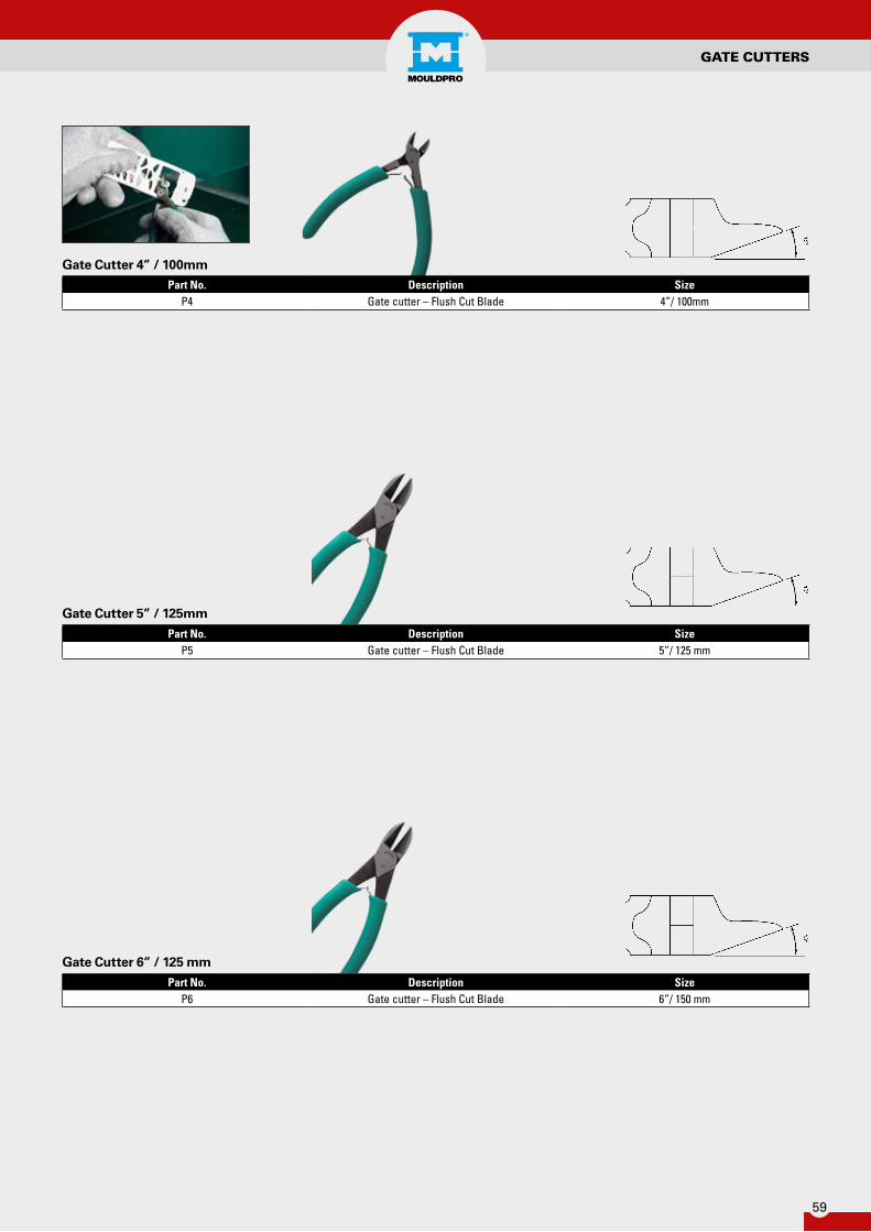
Part No. Description SizeP4 Gate cutter – Flush Cut Blade 4”/ 100mm
Part No. Description SizeP5 Gate cutter – Flush Cut Blade 5”/ 125 mm
Part No. Description SizeP6 Gate cutter – Flush Cut Blade 6”/ 150 mm
Gate Cutter 4” / 100mm
Gate Cutter 5” / 125mm
Gate Cutter 6” / 125 mm
gATE CUTTERS
60
gATE CUTTERS/CERAMIC KNIVES
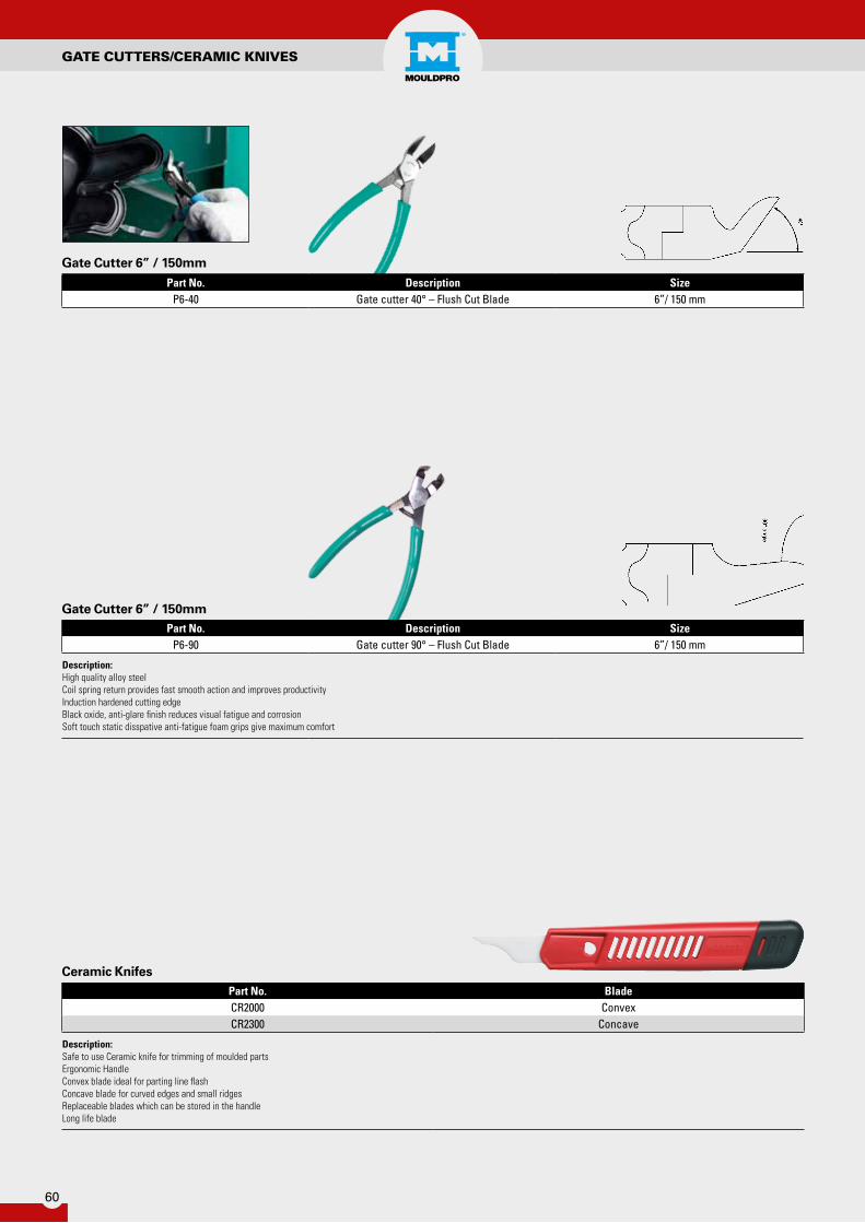
Part No. Description SizeP6-40 Gate cutter 40° – Flush Cut Blade 6”/ 150 mm
Part No. Description SizeP6-90 Gate cutter 90° – Flush Cut Blade 6”/ 150 mm
Description: High quality alloy steelCoil spring return provides fast smooth action and improves productivityInduction hardened cutting edgeBlack oxide, anti-glare finish reduces visual fatigue and corrosionSoft touch static disspative anti-fatigue foam grips give maximum comfort
Gate Cutter 6” / 150mm
Gate Cutter 6” / 150mm
Part No. BladeCR2000 ConvexCR2300 Concave
Description: Safe to use Ceramic knife for trimming of moulded partsErgonomic HandleConvex blade ideal for parting line flashConcave blade for curved edges and small ridgesReplaceable blades which can be stored in the handleLong life blade
Ceramic Knifes

61
Part No. Description SizeBC9 60° Needle Nose 9”/ 230 mm
Bronze Plier
Part No. Description SizeBC6 60° Needle Nose 6”/ 150 mm
Bronze Plier
DE-BURRINg/BRONzE PLIERS
Part No. Blade UOME02000 Plastic Edge Off EachBS1010 Replacement Blades PK 10
Description: Light Duty tool for fine de-flashing and deburring. Plastic handle Removable S10 bladeHeavy Duty 3.2mm ShankHandy Pocket Clip
De-Burring Tool

62
BRONzE PLIER
Part No. Description SizeBL9 Straight Needle Nose 9”/ 230 mm
Bronze Plier
Part No. Description SizeBD6 Side Cutter 6”/ 150 mm
Description: High quality Bronze Pliers, reduce risk of damaging the mould
Bronze Plier
Part No. Description SizeBL6 Straight Needle Nose 6”/ 150 mm
Bronze Plier

63
Part No. SizeWG08/R8 MULTI
Description: Ideal for handling hot machine parts
Leather Gloves
Part No. Description Size704-31 Knock out Bar ø 8705-31 Replacement Bar ø 8
Description:The Plast Speer is a simple but effective tool that combines a tough steel rod with threaded brass replaceable tips that prevent damage to the mould surfaceThe quickly replaced threaded brass tip ensures that the rod never gets too short or wears out and minimises the risk of burningThe steel rod never wears out and the end will not ’mushroom’ like a solid brass rod- Steel Rod has an anti rust finish- Steel Rod has 10mm Flat for simple removal of used tips- Brass Tip is machined to fine point- Supplied complete with one replacement tipSteel Rod: 13mm dia. / 420mm lengthBrass Tip: 8mm dia. / 105mm length
Part No. Description LengthBRT5 5mm Diameter 350mm
BRT5/90 5mm Diameter / 90 Degree 350mmBRT8 8mm Diameter 400mmBRTK Kit Comprising BRT5 / BRT5/90 / BRT8
Description:A range of brass hand tools manufactured from high grade brass for safely working on mould tools without damaging the mould surface; ideal for removing frozen sprues or stuck parts.The tips are supplied blunt and may be shaped to suit specific requirements.
Knock Out Bar
Brass Tools
TOOLS & ACCESSORIES

64
COPPER MALLET/POLISHINg EqUIPMENT
Diamond paste
Part No. Micron SizeMPD1 1 5 gr.MPD3 3 5 gr.MPD6 6 5 gr.MPD8 8 5 gr.
MPD14 14 5 gr.MPD25 25 5 gr.
Description: High contration diamond paste for speed polish and repair of moulds.Use with felt, or wood sticks or points
Copper and Rawhide Mallet
Part No. Size Ø Weight LengthTHO208 A 25 mm 355 g 230 mmTHO210 1 32 mm 710 g 270 mmTHO212 2 38 mm 1070 g 305 mmTHO214 3 44 mm 1600 g 305 mmTHO216 4 50 mm 2380 g 355 mm
Description: Malleable-iron head fitted with one face of pure copper, the other highly compressed buffalo rawhide.Wooden Handle
Handpads
Part No. Size Grade Colour UOMNHP021 155x225 mm. Fine Green 10 pcs.NHP006 155x225 mm. Very Fine Maroon 10 pcs.NHP008 155x225 mm. Ultra Fine Light Grey 10 pcs.
Description: A range of general purpose handpads designed for cleaning and finishing applications
Copper GauzePart No. Width Length
CG30 130 30m.
Description: Knitted Copper, Reversible Soft Copper perfect for cleaning Screws etc.

65
Part No. D L d1FIL612C 6 12 3
FIL1012C 10 12 3FIL1219C 12 19 3FIL1632C 16 32 3FIL1932C 19 32 6FIL3238C 32 38 6
Part No. D L d1FIL616K 6 16 3
FIL1012K 10 12 3FIL1219K 12 19 3FIL1625K 16 25 3FIL1925K 19 25 6
Part No. d1 d2 LFIL66100 6 6 100
FIL1010150 10 10 150
Felt bobs Cylindrical
Felt bobs Cone shape
Felt Sticks Hardened
FELT POLISHINg TOOLS

66
BRUSHES
Small Bore Cleaning Brush (Brass/Nylon)300mm Long (100mm Brush) with loop handle
Condenser Brush
Part No. Brass Part No. Nylon Diameter Brush Length Total lengthSB3 SN3 3 100 300SB4 SN4 4 100 300SB5 SN5 5 100 300SB6 SN6 6 100 300SB8 SN8 8 100 300
SB10 SN10 10 100 300SB12 SN12 12 100 300SB15 SN15 15 100 300SB20 SN20 20 100 300SB25 SN25 25 100 300
Part No. Brass Part No. Nylon Diameter mm Thread Brush Length Total LengthCBB6 CBN6 6 M6 80 115CBB8 CBN8 8 M6 80 115
CBB10 CBN10 10 M6 80 115CBB12 CBN12 12 M6 80 115CBB14 CBN14 14 M6 80 115CBB16 CBN16 16 M6 80 115CBB18 CBN18 18 M6 80 115CBB20 CBN20 20 M6 80 115
Description: Single Spiral Brush with thread ideal for cleaning inside bores.

67
BRUSHES
Handles and Extensions
Barrel Cleaning Brushes
Part No. Thread Type LengthHC1000 M6 Handle 1000 mm.EC1000 M6 Extension 1000 mm.HB1000 W 1/2" Handle 1000 mm.EB1000 W 1/2" Extension 1000 mm.
Part No. Diameter mm Diameter Inch Thread Brush Length Total LengthBC30 30 1-1/4" W 1/2" 100 160BC35 35 1-1/4" W 1/2" 100 160BC40 40 1-1/2" W 1/2" 100 160BC44 44 1-1/4" W 1/2" 100 160BC50 50 2" W 1/2" 100 160BC57 57 2-1/4" W 1/2" 100 160BC63 63 2-1/2" W 1/2" 100 160BC69 69 2-3/4" W 1/2" 100 160BC75 75 3" W 1/2" 100 160BC82 82 3-1/4" W 1/2" 100 160BC88 88 3-3/8" W 1/2" 100 160BC94 94 3-5/8" W 1/2" 100 160BC101 101 4” W 1/2" 100 160BC125 125 5” W 1/2" 100 160BC150* 150 6” W 1/2" 100 160BC200* 200 8” W 1/2" 100 160
Description: * Single Spiral Heavy Duty Double Spiral Steel Brush ideal for cleaning Barrel Cylinders of Injection Moulding Machines.

68
08.MacHInE accESSorIES
Moulds Screens
Mould Align
Mould Clamping
Machine Mounts
69
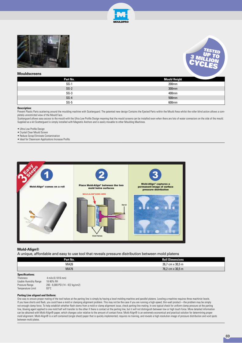
Part No. Mould HeightSG-1 200mmSG-2 300mmSG-3 400mmSG-4 500mmSG-5 600mm
Description: Prevent Plastic Parts scattering around the moulding machine with Scatterguard. The patented new design Contains the Ejected Parts within the Mould Area whilst the roller blind action allows a com-pletely unrestricted view of the Mould Face.Scatterguard allows easy access to the mould with the Ultra Low Profile Design meaning that the mould screens can be installed even when there are lots of water connectors on the side of the mould.Supplied as a kit Scatterguard is simply installed with Magnetic Anchors and is easily movable to other Moulding Machines.
• Ultra Low Profile Design• Crystal Clear Mould Screen• Reduce Scrap Eliminate Contamination• Ideal for Cleanroom Applications Increase Profits
Part No. Roll DimensionsMA26 26,7 cm x 30,5 mMA76 76,2 cm x 30,5 m
Specifications:Thickness 4 mils (0.1016 mm)Usable Humidity Range 10-90% RHPressure Range 200 - 6,000 PSI (14 - 422 kg/cm2)Temperature Limit 93°C
Parting Line aligned and Uniform:One way to ensure proper mating of the tool halves at the parting line is simply by having a level molding machine and parallel platens. Leveling a machine requires three machinist levels. If you have shorts and flash, you could have a mold or clamping alignment problem. This may not be the case if you are running a high-speed, thin-wall product—the problem may be simply not enough clamp force. To help establish whether flash stems from a mold or clamp alignment issue, check parting-line mating. In one typical check for uniform clamp pressure at the parting line, blueing agent applied to one mold half will transfer to the other if there is contact at the parting line, but it will not distinguish between low or high touch force. More detailed information can be obtained with Mold-Align® paper, which changes color relative to the amount of contact force. Mold-Align® is an extremely economical and practical solution for determining propermold alignment. Mold-Align® is a self contained (single sheet) paper that is quickly implemented, requires no training, and reveals a high resolution image of pressure distribution and void spotsbetween mold plates.
Mouldscreens
Mold-Align®A unique, affordable and easy to use tool that reveals pressure distribution between mold platens

70
Part No. Nut DIN6314 B1xL D A B2 E1 E21330-11x80 10 11x80 M10 15 30 15 301330-14x100 12+14 14x100 M12 20 40 21 401330-14x125 12+14 14x125 M12 20 40 21 501330-18x125 16+18 18x125 M16 25 50 26 451330-18x160 16+18 18x160 M16 25 50 26 651330-22x160 20+22 22x160 M20 30 60 30 601330-22x200 20+22 22x200 M20 30 60 30 801330-26x160 24+28 26x160 M24 30 70 35 601330-26x200 24+28 26x200 M24 35 70 35 801330-26x250 24+28 26x250 M24 35 70 35 1001330-26x315 24+28 26x315 M24 40 70 35 1301330-33x315 36+42 33x315 M24 50 80 45 1301330-43x400 42 43x400 M24 60 100 100 150
Part No. Thread Size LengthKP-M6 M6 3mmKP-M8 M8 4mm
KP-M10 M10 4mmKP-M12 M12 5mmKP-M14 M14 6mmKP-M16 M16 6mmKP-M18 M18 6mmKP-M20 M20 6mmKP-M22 M22 8mmKP-M24 M24 8mmKP-M30 M30 10mm
Description: Ideal for Mould Clamping
Straight Clamp with support hole(supplied without adjusting screw)
Thick Washer

71
MOULD CLAMPINg
Part No. Size E M R S6330B-6 M6 11,5 9 9 106330B-8 M8 15 12 12 136330B-10 M10 19,6 15 15 176330B-12 M12 21,9 18 17 196330B-14 M14 25,4 21 20 226330B-16 M16 27,7 24 22 246330B-18 M18 31,2 27 24 276330B-20 M20 34,6 30 27 306330B-22 M22 36,9 33 30 326330B-24 M24 41,5 36 32 366330B-30 M30 53,1 45 41 466330B-36 M36 63,5 54 50 55
Description: Hexagon Nut DIN 6330BMaterial: Ck45 DINHardness: 30-32 HRCBlack Coating
Hexagon Nut
Part No. M L D K1490-10x42 M10 42 30 81490-12x50 M12 50 36 101490-12x95 M12 95 36 101490-16x62 M16 62 45 131490-16x97 M16 97 45 13
1490-16x117 M16 117 45 131490-20x62 M20 62 50 131490-20x97 M20 97 50 13
1490-20x117 M20 117 50 131490-24x81 M24 81 50 14
1490-24x116 M24 116 50 14
Description: Material: Ck45 DIN Black Coating
Adjusting Screw
72
6379-6x32 M 6x 32 9 166379-6x40 M 6x 40 9 206379-6x50 M 6x 50 9 306379-6x63 M 6x 63 9 406379-6x80 M 6x 80 9 506379-8x40 M 8x 40 11 206379-8x63 M 8x 63 11 406379-8x80 M 8x 80 11 50
6379-8x100 M 8x100 11 636379-8x125 M 8x125 11 756379-8x160 M 8x160 11 1006379-10x50 M10x 50 13 256379-10x80 M10x 80 13 50
6379-10x100 M10x100 13 756379-10x125 M10x125 13 756379-10x160 M10x160 13 1006379-10x200 M10x200 13 1256379-12x50 M12x 50 15 256379-12x63 M12x 63 15 326379-12x80 M12x 80 15 50
6379-12x100 M12x100 15 636379-12x125 M12x125 15 756379-12x160 M12x160 15 1006379-12x200 M12x200 15 1256379-14x63 M14x 63 17 326379-14x80 M14x80 17 50
6379-14x100 M14x100 17 636379-14x125 M14x125 17 756379-14x160 M14x160 17 1006379-14x200 M14x200 17 1256379-14x250 M14x250 17 1606379-16x63 M16x 63 19 326379-16x80 M16x 80 19 50
6379-16x100 M16x100 19 636379-16x125 M16x125 19 756379-16x160 M16x160 19 1006379-16x200 M16x200 19 1256379-16x250 M16x250 19 1606379-16x315 M16x315 19 1806379-16x500 M16x500 19 3156379-18x80 M18x 80 23 50
6379-18x125 M18x125 23 756379-18x160 M18x160 23 1006379-18x200 M18x200 23 1256379-18x250 M18x250 23 1506379-18x315 M18x315 23 1806379-20x80 M20x 80 27 32
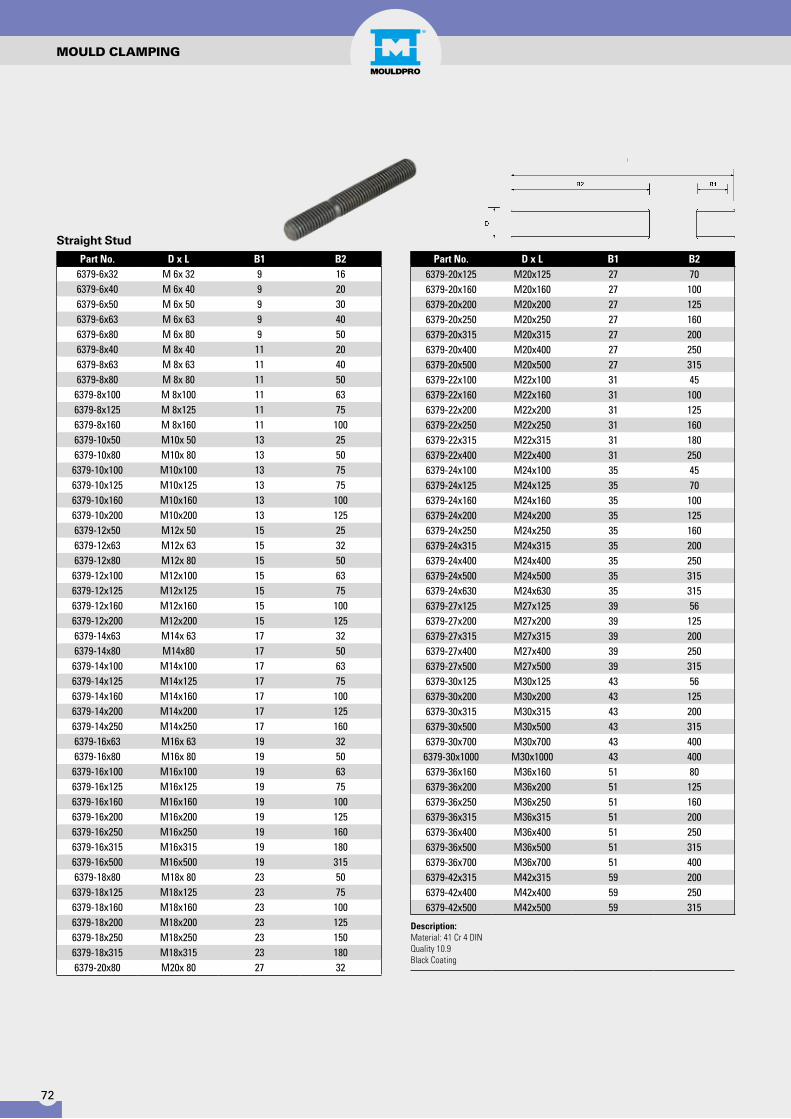
Straight Stud
6379-20x125 M20x125 27 706379-20x160 M20x160 27 1006379-20x200 M20x200 27 1256379-20x250 M20x250 27 1606379-20x315 M20x315 27 2006379-20x400 M20x400 27 2506379-20x500 M20x500 27 3156379-22x100 M22x100 31 456379-22x160 M22x160 31 1006379-22x200 M22x200 31 1256379-22x250 M22x250 31 1606379-22x315 M22x315 31 1806379-22x400 M22x400 31 2506379-24x100 M24x100 35 456379-24x125 M24x125 35 706379-24x160 M24x160 35 1006379-24x200 M24x200 35 1256379-24x250 M24x250 35 1606379-24x315 M24x315 35 2006379-24x400 M24x400 35 2506379-24x500 M24x500 35 3156379-24x630 M24x630 35 3156379-27x125 M27x125 39 566379-27x200 M27x200 39 1256379-27x315 M27x315 39 2006379-27x400 M27x400 39 2506379-27x500 M27x500 39 3156379-30x125 M30x125 43 566379-30x200 M30x200 43 1256379-30x315 M30x315 43 2006379-30x500 M30x500 43 3156379-30x700 M30x700 43 400
6379-30x1000 M30x1000 43 4006379-36x160 M36x160 51 806379-36x200 M36x200 51 1256379-36x250 M36x250 51 1606379-36x315 M36x315 51 2006379-36x400 M36x400 51 2506379-36x500 M36x500 51 3156379-36x700 M36x700 51 4006379-42x315 M42x315 59 2006379-42x400 M42x400 59 2506379-42x500 M42x500 59 315
Description:Material: 41 Cr 4 DIN Quality 10.9 Black Coating
Part No. D x L B1 B2 Part No. D x L B1 B2
MOULD CLAMPINg

73
MOULD CLAMPINg
Part No. D x Nut A E H K508-6x8 M 6x 8 7,7 13 10 6
508-8x10 M 8x10 9,7 15 12 6508-8x12 M 8x12* 11,7 18 14 7508-10x12 M10x12 11,7 18 14 7508-8x14 M 8x14* 13,7 22 16 8508-10x14 M10x14* 13,7 22 16 8508-12x14 M12x14 13,7 22 16 8508-8x16 M 8x16* 15,7 25 18 9508-10x16 M10x16* 15,7 25 18 9508-12x16 M12x16* 15,7 25 18 9508-14x16 M14x16* 15,7 25 18 9508-8x18 M 8x18* 17,7 28 20 10508-10x18 M10x18* 17,7 28 20 10508-12x18 M12x18* 17,7 28 20 10508-14x18 M14x18* 17,7 28 20 10508-16x18 M16x18 17,7 28 20 10508-16x20 M16x20* 19,7 32 24 12508-18x20 M18x20* 19,7 32 24 12508-16x22 M16x22* 21,7 35 28 14508-18x22 M18x22* 21,7 35 28 14508-20x22 M20x22 21,7 35 28 14508-16x24 M16x24* 23,7 40 32 16508-20x24 M20x24* 23,7 40 32 16508-22x24 M22x24* 23,7 40 32 16508-16x28 M16x28* 27,7 44 36 18508-20x28 M20x28* 27,7 44 36 18508-22x28 M22x28* 27,7 44 36 18508-24x28 M24x28 27,7 44 36 18508-24x36 M24x36* 35,6 54 44 22508-30x36 M30x36 35,6 54 44 22
* Old standard 1928
Description: T-Clamp DIN 508 Material: Ck45 DIN Hardness: 30-32 HRC Black Coating
T - Clamp

74
MACHINE MOUNTS
Part No. Diameter Load (kg) Adjusting Screw HeightSMM01 80mm 200kg M12x1.25x120 38-50mmSMM02 120mm 400kg M16x1.5x120 46-59mmSMM03 160mm 1000kg M20x1.5x170 53-68mmSMM04 160mm 2500kg M20x1.5x170 54-69mmSMM05 200mm 3800kg M20x1.5x170 56-71mm
Description:Up to 15 mm. Of AdjustmentGalvanised Steel FinishSupplied Complete with Adjusting Screw
Part No. Diameter Load (kg) Thread HeightHDM01 50mm 150kg M10x1.5 21-30mmHDM02 80mm 500kg M12x1.75 32-44mmHDM03 120mm 1200kg M16x2.0 39-55mmHDM04 160mm 3000kg M20x1.5 39-55mmHDM05 200mm 4000kg M20x1.5 55-75mmHDM06 230mm 5000kg M20x1.5 55-75mmHDM07 230mm 5000kg M24x1.5 55-75mmHDM08 320mm 12000kg M24x1.5 70-100mm
Description:Designed to provide effective vertical and horizontal shock absorbtion, vibration isolation and damping as well as easy and precise leveling of injection moulding machinery.Premium QualityHigh CapacityUp to 30mm of AdjustmentOil and Chemical ResistanceBright Zinc Plated Steel Finish
Part No. Thread Length Spanner mmH1008 M10x1.5 80mm 17 A/FH1210 M12x1.75 100mm 19 A/FH1610 M16x2.0 100mm 24 A/FH1615 M16x2.0 150mm 24 A/FH2015F M20x1.5 150mm 30 A/FH2018F M20x1.5 180mm 30 A/FH2415F M24x1.5 150mm 36 A/FH2418F M24x1.5 180mm 36 A/F
Standard Machine MountsSupplied with Adjusting Screws
Heavy Duty Machine MountsSupplied without Adjusting Screws
Hex Head Adjusting Screw

75
09.lIFtIng
Eyebolts & Shackles
Round Slings

76
EyEBOLTS/SWIVEL EyEBOLTS
Part No. d l D d2 L WLLEBGM8 M8 13 36 20 36 140kg
EBGM10 M10 17 45 25 45 230kgEBGM12 M12 20 54 30 53 340kgEBGM16 M16 27 63 35 62 700kgEBGM20 M20 30 72 40 71 1200kgEBGM24 M24 36 90 50 90 1800kgEBGM30 M30 45 108 60 109 3600kgEBGM36 M36 54 126 70 128 5100kgEBGM42 M42 63 144 80 147 7000kgEBGM48 M48 68 160 90 168 8600kgEBGM56 M56 78 184 110 187 11500kg
Lifting Eyebolts - Nickel Plated DIN 508
Swivel Eyebolts
Part No. WLL Safety factor Diameter L1 N.m X S A B C D WeightSEB M 16 1,6 TO 5 M 16 (x2) 27 50 35 8 38 45 90 78 0,8 KgSEB M 20 2,5 TO 5 M 20 (x2,5) 30 100 35 8 38 45 90 78 0,8 KgSEB M 24 4 TO 5 M 24 (x3) 36 160 50 14 58 70 134 115 2,6 KgSEB M 30 6,3 TO 5 M 30 (x3,5) 45 250 50 14 58 70 134 115 2,7 KgSEB M 36 10 TO 5 M 36 (x4) 54 320 70 14 88 94 190 166 8 KgSEB M 42 12,5 TO 5 M 42 (x4,5) 63 400 70 14 88 94 190 166 8,1 KgSEB M 48 15 TO 4 M 48 (x5) 68 600 70 19 88 94 190 166 9 Kg
90°
360°
M - 6 gUNC - 2 A
M - 6 HUNC - 2 B

77
SHACKLES
Double Swivel Ring
Part No. WLL Safety factor Diameter Ø P L1 N.m S1 S2 A B C D E F G WeightDSR M 4* 0,05 TO 5 M4 (x0,7) 15 2 3 33 30 30 38 27 14 53 0,3 KgDSR M 5* 0,075 TO 5 M5 (x0,8) 15 3 4 33 30 30 38 27 14 53 0,3 KgDSR M 6* 0,1 TO 5 M6 (x1) 15 4 5 33 30 30 38 27 14 53 0,3 KgDSR M 8 0,3 TO 5 M8 (x1,25) 14 6 8 16 33 30 30 38 27 14 53 0,3 Kg
DSR M 10 0,6 TO 5 M10 (x1,50) 17 10 8 16 33 30 30 38 27 14 53 0,3 KgDSR M 12 1 TO 5 M12 (x1,75) 21 15 8 16 33 30 30 38 27 14 53 0,3 Kg
DSR M 14* 1,3 TO 5 M14 (x2) 23 30 8 20 45 42 45 54 38 17 76 0,9 KgDSR M 16 1,6 TO 5 M16 (x2) 27 50 8 20 45 42 45 54 38 17 76 0,9 Kg
DSR M 18* 2 TO 5 M18 (x2,5) 27 70 8 20 45 42 45 54 38 17 76 0,9 KgDSR M 20 2,5 TO 5 M20 (x2,5) 30 100 8 20 45 42 45 54 38 17 76 0,9 Kg
DSR M 22* 3 TO 5 M22 (x2,5) 33 120 14 24 62 55 60 83 55 25 117 2,6 KgDSR M 24 4 TO 5 M24 (x3) 36 160 14 24 62 55 60 83 55 25 117 2,6 Kg
DSR M 27* 5 TO 5 M27 (x3) 40 200 14 24 62 55 60 83 55 25 117 2,7 KgDSR M 30 6,3 TO 5 M30 (x3,5) 45 250 14 24 62 55 60 83 55 25 117 2,7 Kg
Description:Double Swivel RingDouble articulation allows it to line up perfectly with the slingTwo ways of tightening: either by open-ended spanner or by Allen keyFrom M8 to M30 as standard; for loads from 0.3 t to 6.3 t
>180°
90°
360°>
M - 6 gUNC - 2 A
M - 6 HUNC - 2 B
Double Swivel Shackle
Part No. WLL Safety factor Diameter L1 N.m S A B C D E F G WeightDSS M 30 7,3 TO 5 M30 (x3,5) 45 250 19 61 31 70 104 73 145 29 5,5 KgDSS M 33* 8 TO 5 M33 (x3,5) 50 250 19 61 31 70 104 73 145 29 5,5 KgDSS M 36 10 TO 5 M36 (x4) 54 320 19 61 31 70 104 73 145 29 5,5 Kg
DSS M 36x3* 10 TO 5 M36 (x3) 54 320 19 61 31 70 104 73 145 29 5,5 KgDSS M 39* 10 TO 5 M39 (x4) 58 320 19 61 31 70 104 73 145 29 5,7 KgDSS M 42 12,5 TO 5 M42 (x4,5) 63 400 19 61 31 70 104 73 145 29 5,8 Kg
DSS M 42x3* 12,5 TO 5 M42 (x3) 63 400 19 61 31 70 104 73 145 29 5,8 KgDSS M 45* 15 TO 4 M45 (x4,5) 63 400 19 61 31 70 104 73 145 29 5,7 KgDSS M 48 20 TO 4 M48 (x5) 68 600 19 79 38 90 125 91 184 33 11 Kg
DSS M 48x3* 20 TO 4 M48 (x3) 68 600 19 79 38 90 125 91 184 33 11 KgDSS M 48x4* 20 TO 4 M48 (x4) 68 600 19 79 38 90 125 91 184 33 11 Kg
DSS M 52* 20 TO 4 M52 (x5) 68 600 19 79 38 90 125 91 184 33 11,2 KgDSS M 56 25 TO 4 M56 (x5,5) 78 600 19 79 38 90 125 91 184 33 11,3 Kg
DSS M 56x4* 25 TO 4 M56 (x4) 78 600 19 79 38 90 125 91 184 33 11,4 KgDSS M 64 32,1 TO 4 M64 (x6) 90 600 19 79 38 95 125 91 184 33 12,2 Kg
DSS M 64x4* 32,1 TO 4 M64 (x4) 90 600 19 79 38 95 125 91 184 33 12,2 Kg
Description:Double Swivel RingDouble articulation allows it to line up perfectly with the slingTwo ways of tightening: either by open-ended spanner or by Allen keyFrom M8 to M30 as standard; for loads from 0.3 t to 6.3 t
360°
90°
360°
M - 6 gUNC - 2 A
M - 6 HUNC - 2 B
78
SWIVEL EyEBOLTS AND SLINgS
Round Slings
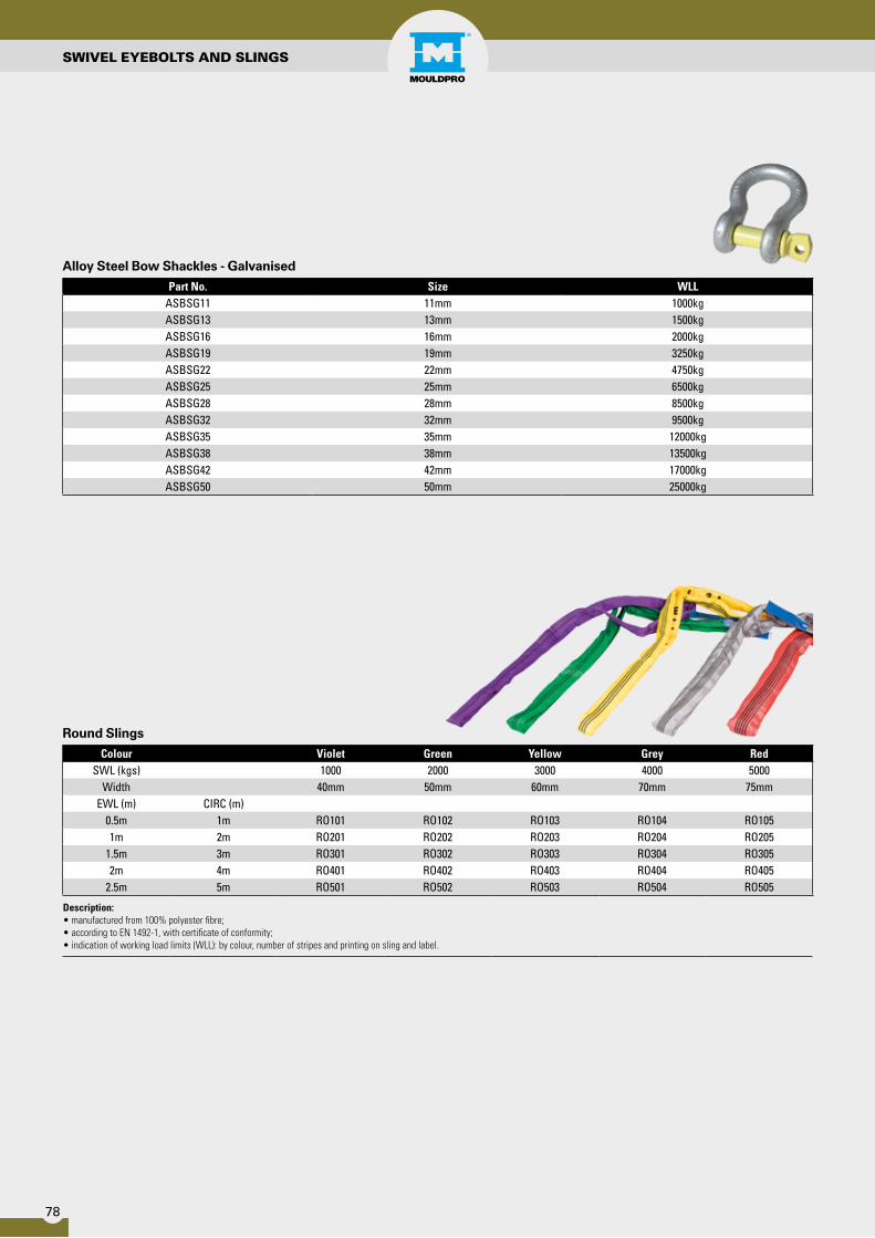
Colour Violet Green Yellow Grey RedSWL (kgs) 1000 2000 3000 4000 5000
Width 40mm 50mm 60mm 70mm 75mmEWL (m) CIRC (m)
0.5m 1m RO101 RO102 RO103 RO104 RO1051m 2m RO201 RO202 RO203 RO204 RO205
1.5m 3m RO301 RO302 RO303 RO304 RO3052m 4m RO401 RO402 RO403 RO404 RO405
2.5m 5m RO501 RO502 RO503 RO504 RO505
Description:• manufactured from 100% polyester fibre;• according to EN 1492-1, with certificate of conformity;• indication of working load limits (WLL): by colour, number of stripes and printing on sling and label.
Part No. Size WLLASBSG11 11mm 1000kgASBSG13 13mm 1500kgASBSG16 16mm 2000kgASBSG19 19mm 3250kgASBSG22 22mm 4750kgASBSG25 25mm 6500kgASBSG28 28mm 8500kgASBSG32 32mm 9500kgASBSG35 35mm 12000kgASBSG38 38mm 13500kgASBSG42 42mm 17000kgASBSG50 50mm 25000kg
Alloy Steel Bow Shackles - Galvanised


Distributor
MOULDPRO A/SBaltorpbakken 10
DK-2750 Ballerup Denmarkwww.mouldpro.com
Phone: + 45 7020 3131 · Fax: + 45 7020 3151