2011 dvm_installation guide
TRANSCRIPT

7/24/2019 2011 DVM_Installation Guide
http://slidepdf.com/reader/full/2011-dvminstallation-guide 1/137

7/24/2019 2011 DVM_Installation Guide
http://slidepdf.com/reader/full/2011-dvminstallation-guide 2/137
Contents
1. General installation Guide
1. Introduction ······································································· 4
2. Product Outline·································································· 53. DVM design process ························································· 7
4. Installation process & Guideline ········································· 8
5. Installation Procedure ························································ 9
2. Preparation for installation
1. Checking the Installation Site ·········································· 252. Product handling ····························································· 29
3. Materials and Tools ························································· 39
3. Guideline for each installation process
1. Sleeve work ····································································· 47
2. Insert work and support work ·········································· 49
3. Concealed Box work ······················································· 51
4. Refrigerant pipe construction ·········································· 52
5. Refrigerant pipe flushing ·················································· 71
6. Drainpipe Work ································································ 73
7. Insulation work ································································ 82
8. Gas leak test ···································································· 84
9. Vacuum drying ································································· 86
10. Charging Refrigerant······················································ 88

7/24/2019 2011 DVM_Installation Guide
http://slidepdf.com/reader/full/2011-dvminstallation-guide 3/137
4. Indoor Units installation
1. Ceiling Cassette Type (1WAY/2WAY/4WAY) ························ 90
2. Duct Type (Slim/MSP)······················································ 963. Ceiling ··········································································· 106
4. Console ········································································· 109
5. Wall-mounted Type ······················································· 111
5. Outdoor Units installation
1. Safety Information ························································ 114
2. Preparing the Installation ················································ 115
3. Selecting Proper Location for Installation ······················· 117
4. Space Requirements ······················································ 118
5. Base Mount Construction ··············································· 120
6. Drain Pipe Installation ····················································· 123
7. Exhaust Duct Installation ················································ 124
8. Installing the Outdoor Unit Harsh Environments ············· 125
9. Louver Installation ·························································· 127
10. Electrical Wiring Work ··················································· 128
11. Pump-Down Operation ················································· 133
12. Pump-Out Procedure ··················································· 134
13. Setting the Option Switches & Function Keys ·············· 135
14. Completing the Installation and Commissioning ··········· 136

7/24/2019 2011 DVM_Installation Guide
http://slidepdf.com/reader/full/2011-dvminstallation-guide 4/137
1. General installation Guide
4
1. Introduction The diagram below illustrates overall configuration of the refrigerant piping for installing a system airconditioner. Multiple outdoor units with variable capacity control are installed in a location with good
air ventilation for cooling and heating and a vibration-proof rubber mat is installed in the bottom of theoutdoor unit to prevent vibration from being transferred to the building. The refrigerant pipe and thecommunication cable from the outdoor unit penetrate the outer wall of the building before reachingthe inner area of the building. When penetrating the outer wall of the building, sleeves should be usedto prevent air leakage and support water proofing. The refrigerant pipes and electrical wiring works forthe indoor unit should be finished by fixing the indoor unit in a level or perpendicular location. In therefrigerant pipe works, you should pay attention to installation of insulation materials as well as branchpipes and its slope. You should also make efforts to remove all alien substances from the inner area ofthe pipe. To apply an air conditioning system for the building, you must first design the overall air conditioningsystem and select components such as outdoor units and indoor units and refer to the constructiondesign diagram in order to prepare a diagram for installing an air conditioning system. System air
conditioner installation vendors should refer to the provided construction diagram when preparing adiagram for installation and purchasing components.

7/24/2019 2011 DVM_Installation Guide
http://slidepdf.com/reader/full/2011-dvminstallation-guide 5/137
Installation guide
5
2. Product Outline
2-1. Outdoor UnitsSamsung provides you the perfectly optimized cooling and heating system with its latest and mostinnovative technology. World’s largest capacity will provide you the powerful performance all year long,no matter how hot or how cold. Furthermore, Samsung’s outdoor units barely make any noise orvibration during operations, and they are perfect for residential and commercial buildings, Always stayrefreshed with Samsung system air conditioner.
1) DVM PLUS III, DVM PLUS III HR
DVM PLUS III, DVM PLUS III HR is a module multi-system air conditioner that has the world'slargest capacity(8~64HP) with the application of a DVI (Digital Vapor Injection) compressor, and
can connect up to a maximum of 64 indoor units.
• The world's largest capacity.- Compact combinations (8~64 hp) : combinations with the models requiring the smallest
installation space- High combinations (16~56 hp) : combinations with highly efficient models
• The highest COP levels in the industry• The smallest instal lat ion space requirement in the world•
The highest heating capacity and COP in low temperature condition (-10°c)• Possible to connect up to 64 indoor units• Digital unit module

7/24/2019 2011 DVM_Installation Guide
http://slidepdf.com/reader/full/2011-dvminstallation-guide 6/137
1. General installation Guide
6
2-2. Indoor Units
Samsung indoor units are not only equipped with high performing functions, but they are also
beautifully designed to enlighten your space. Different types of indoor units will be more than enoughto satisfy needs of your space and yourself. Only Samsung’s beautiful indoor units will provide you theconditioned air that you can enjoy.

7/24/2019 2011 DVM_Installation Guide
http://slidepdf.com/reader/full/2011-dvminstallation-guide 7/137
Installation guide
7
3. DVM design processDVM is a variable multi air conditioner that modulates its performance by different conditions such as
design temperature, indoor and outdoor unit combination rates, heating operation rates, piping length,and level difference. It is important to select the appropriate design condition to the load of each room.
• Design temperature• Calculate cooling and heating loads• Power supply, piping length and level difference
• Consider design temperature conditions to selectlarger indoor types than actual load.
• Determine outdoor units by the sum of the capacityof preliminary selected indoor units: At this time,decide how much combination ratio to permit.
• Calculate actual capacity ofoutdoor units consideringdesign temperature, indoor andoutdoor unit combination ratio,piping length, level difference,heating operation rates, etc.
• Calculate actual capacity of each indoorunit based on the calculated outdoorcapacity.
• If Indoor units’ actual capacity is lower than the load,reselect ones with a larger capacity. Depending ondesigners’ own discretion.
• If there is no indoor unit with a larger capacity, addanother indoor unit.

7/24/2019 2011 DVM_Installation Guide
http://slidepdf.com/reader/full/2011-dvminstallation-guide 8/137
1. General installation Guide
8
4. Installation process & GuidelineStriking a balance between System Installation & General Construction Work.
.
Note: 1. Work scope should be thoroughly clarified. (This applies particularly to work relating tothe connection of control wiring, fitting of remote controller and central control panel,boundary work on areas such as connection of drain piping and humidification supplypiping, inspection and foundation)
2. Keep a constant check on the progress of the construction work to avoid deviationsfrom the air conditioning work schedule.
3. For sleeve and insert work the positions of ceiling girders should be confirmed andsleeve and insert requirement, hole diameters, positioning and numbers decided. Thisis particularly important in the case of sleeves for drain piping.

7/24/2019 2011 DVM_Installation Guide
http://slidepdf.com/reader/full/2011-dvminstallation-guide 9/137
Installation guide
9
5. Installation Procedure
5-1. Procedure
Note The above list indicates the order in which the individual work operations are normally
carried out but this order may be varied according to the local conditions.

7/24/2019 2011 DVM_Installation Guide
http://slidepdf.com/reader/full/2011-dvminstallation-guide 10/137
1. General installation Guide
10
5-2. Step by Step Installation Procedure
1) Refrigerant piping
(1) Pre-estimation with the drawing
Picture
Work Description Things to do Check point
Measure the actualconstructiondrawing.
Check what and howmuch you prepare forinstallation.
Fully familiarize with the diagramto prevent problems whileworking on the site.
(2) Straightening the refrigerant pipe
Picture
Work Description Things to do Check point
Straighten therefrigerant pipe.
Considering the job sitecondition, measure theaccurate length to cut.
- Remove sharp object orsomething that can causedeformation of the pipe inadvance.
- Do not apply excessive forcefor straightening the pipe.
(3) Marking
Picture
Work Description Things to do Check point
Accurate markingof the length.
Consider the diagram andthe actual site conditionwhen marking it.
Compare the marked area withthe diagram accurately.
(4) Cutter (cutting)
Picture
Work Description Things to do Check point
Use a coppercutter to cut it.
- Use proper Size & Quality
Cutting tool
- Do not apply excessive
force.
(Prevent deformation of the
pipe.)
While cutting the copper pipe,check for deformation of thepipe.

7/24/2019 2011 DVM_Installation Guide
http://slidepdf.com/reader/full/2011-dvminstallation-guide 11/137
Installation guide
11
(5) Pipe cutting
Picture
Work Description Things to do Check point
Cut the pipe.Prevent foreignsubstances fromentering the pipe.
- Check if foreign substancesare removed from the pipe.
(If foreign substances arefound, it can causeperformance degradation andmalfunctions.)
(6) Removing burr
Picture
Work Description Things to do Check point
Removing burr
- Remove burrs so thatthe cut side of the pipeis smooth.
- Remove burr in adownward direction tokeep foreignsubstances fromentering the pipe.
Check for burr residuals in thepipe.
(7) Taping
Picture
Work Description Things to do Check point
Taping Tape the pipe to keepforeign substances fromentering the pipe.
Check if taping is done firmly.
(8) Ready for piping works
Picture
Work Description Things to do Check point
Work completed.Store it in a safe place toprevent damage.
Store the pipe in a safe placenot affected by other works.Remove all other substancesfrom surroundings.

7/24/2019 2011 DVM_Installation Guide
http://slidepdf.com/reader/full/2011-dvminstallation-guide 12/137
1. General installation Guide
12
(9) Anchor works
Picture
Work Description Things to do Check point
Refer to theapprovedconstructiondiagram whenmarking the indoorunit installationlocations and makea hole for anchorinstallation.
Familiarize with theconstruction diagram.
- Accurate locationmarking
- Prevent scattering.
- Use a reel wire support.
- Safeguard against fallingaccidents.
(10) Full threads bolt and C-channel fixing
Picture
Work Description Things to do Check point
Fixing the fullthreads bolt andthe c-channel.
Prevent twisting of thepipe.Do not damage theinsulation materials.
Check for pipe damage.Check interferences.Obey the separation of thechannels. (1.2 to 1.5 meter)
2) Refrigerant pipe construction (branch pipe works)
(1) Preparing a branch pipe
Picture
Work Description Things to do Check point
Preparing abranch pipe.
Prepare a branch pipe. Check for damage in thebranch pipes.
(2) Connecting the branch pipes
Picture
Work Description Things to do Check point
Connecting thebranch pipes.
When making aconnection, do not applyexcessive force that mightdamage the pipe.
Check the connection.
Use Branch kit for the pipeconnection.
(Damage and exterior testson the branch pipes.)

7/24/2019 2011 DVM_Installation Guide
http://slidepdf.com/reader/full/2011-dvminstallation-guide 13/137
Installation guide
13
(3) Brazing the branch pipes
Picture
Work Description Things to do Check point
Brazing thebranch pipe.
- Nitrogen substitutedbrazing works on thebranch pipe to preventgeneration of foreignsubstance/oxide
- Check for adequatepressure (0.01 to0.1kg/cm
2 )
Check the pressure and entryof nitrogen.
3) Refrigerant pipe works (air tightness works)
(1) Entry of nitrogen
Picture
Work Description Things to do Check point
Entry of nitrogen.
Inject nitrogen tothe pipe to testleakages.
Inject nitrogen at theproper pressure.
1st: 10kg/cm
2
2nd
: 41kg/cm2
In the presence of themanager, check air tightness.Fill out the check forms.
(2) Finishing the end of the pipe
Picture
Work Description
Things to do Check point
Wrap the end ofthe pipe beforeconnecting theequipment, sothat nitrogenwon’t escape.
Sufficient brazing on theend of the pipe.
Visual inspection
(3) Pressure gauge attached
Picture
Work Description Things to do Check point
Mark the 1st and
2nd
pressure tosee if it leaks.
1st: 10kg/cm
2
2nd
: 28kg/cm2 look at the
scale.
Check for leakages.

7/24/2019 2011 DVM_Installation Guide
http://slidepdf.com/reader/full/2011-dvminstallation-guide 14/137
1. General installation Guide
14
(4) Insulation of the branch pipe
Picture
Work Description Things to do Check point
Insulate the pipe ifthere is nonitrogen leakage.
Check for leakages. Check for leakages.
(5) Insulation of the branch pipe
Picture
Work Description Things to do Check point
Insulation of thebranch pipe
Dense fill up to preventmissing insulation materialand swelling.
Check the insulationcondition.
(6) Slope adjustment of the branch pipe
Picture
Work Description Things to do Check point
Check thelevelness of thepipe.
Do not exceed thelevelness limit of 15degrees.
Check the levelness condition.
4) Drainpipe construction
(1) Inserting insulation materials
Picture
Work Description Things to do Check point
Insert theinsulationmaterials into thePVC pipe.
Do not damage theinsulation materials.
- Check for damage in theinsulation materials.
- Check for damage in thepipe.

7/24/2019 2011 DVM_Installation Guide
http://slidepdf.com/reader/full/2011-dvminstallation-guide 15/137
Installation guide
15
(2) Mounting the drainpipe
Picture
Work Description Things to do Check point
Fix the drainpipein the channel orhanger.
A group of two personshould work on the pipe(not using excessiveforce).
Check the channel/hangerfixing intervals (1.5m orless)
(3) Checking the drain slope
Picture
Work Description Things to do Check point
Checking thegradients.
Obtain good slope tofacilitate smoothdrainage of thecondensed water.(1/100)
Check the slope.
(4) Pipe connection
Picture
Work Description Things to do Check point
Connect thepipes, checkingthoroughly if thereis leakage on it
Apply sufficient bond tothe pipe.
- Do not install in thewinter season.
(5) Pipe connection and socket works on the indoor unit side
Picture
Work Description Things to do Check point
Use the drainpipecomponents forthe indoor unitside.
Check the height andmaintain the drain slopewhile do the drain pipework
Check the height.

7/24/2019 2011 DVM_Installation Guide
http://slidepdf.com/reader/full/2011-dvminstallation-guide 16/137
1. General installation Guide
16
(6) Pipe work on the indoor unit side
Picture
Work Description Things to do Check point
Pipe work on theindoor unit side.
Secure a slope (1/100) Check the slope.
(7) Air vent installation
Picture
Work Description Things to do Check point
Install a vent tofacilitate smoothdrainage of water.
Install one unit at theend of the equipment.
Check vents installation.
(8) Water containing test
Picture
Work Description Things to do Check point
Pour the water inthe highest point totest it.
Check the pipe slope.If there is a problem,readjust the slope.
Check the slope and testwater leakage.
(9) Connecting the vertical pipe
Picture
Work Description Things to do Check point
If there is noproblem in theabove items,connect the verticalpipe.
- Secure bondingworks.
- Insulation works
Must check the pipe pit’sinner area before finishingthe wall.

7/24/2019 2011 DVM_Installation Guide
http://slidepdf.com/reader/full/2011-dvminstallation-guide 17/137
Installation guide
17
5) Power communication works
(1) Power cable pipe works
Picture
Work Description Things to do Check point
Place a powercable pipe in thecorrect location.
Use Standard qualitymaterials.
Check for bending of thepipe.
(2) Inserting cables
Picture
Work Description Things to do Check point
Insert the standardpowercommunicationcable in the pipe.
Be careful not todamage the cable whileinserting it.
Check the cable condition.
6) Indoor unit installation
(1) Location determination
Picture
Work Description Things to do Check point
Select an accuratelocation (check thediagram and on-sitemeasurement)
Fully familiarize with thediagram and markaccurate locations.Select a location with alaser point.
Check if it is in accordancewith the diagram.
(2). Fastener / Anchor Bolt
Picture
Work Description Things to do Check point
Anchor works onaccurate points.
- Anchor drilling
- Full threads boltsmounting
Check the condition of thefull thread bolts.

7/24/2019 2011 DVM_Installation Guide
http://slidepdf.com/reader/full/2011-dvminstallation-guide 18/137
1. General installation Guide
18
(3) Connecting the equipment
Picture
Work Description Things to do Check point
Mounting anindoor unit.
A group of two workson the indoor unit.
Check for levelness of theindoor unit and damage tothe indoor unit.
(4) Inserting a vibration-proof rubber mat
Picture
Work Description Things to do Check point
Insert a vibrationproof rubber matbetween the boltand the indoor unitto prevent transfersof the vibration.
Do not allow thevibration proof rubbermat to be inclinedtoward either side. Donot omit any of them.
Check the insertion conditionof the vibration proof rubbermat.
(5) Check the horizontal height
Picture
Work Description Things to do Check point
Adjust thehorizontal height.
Check if the indoor unitis horizontally flat?
Considering the ceilingfinishing line, check yourinstallation.
(6) Installation completed
Picture
Work Description Things to do Check point
- - -

7/24/2019 2011 DVM_Installation Guide
http://slidepdf.com/reader/full/2011-dvminstallation-guide 19/137
Installation guide
19
(7) Connecting the power communication cables
Picture
Work Description Things to do Check point
Connect thepowercommunicationcable to the indoorunit.
Use a ring terminal tomake a connection.
Check if the ring terminal isused.
(8) Drain insulation
Picture
Work Description Things to do Check point
Pipe insulationworks.
Do not damage theinsulation materials.
Check the insulationmaterials and drainageslope.
(9) Wrapping indoor unit
Picture
Work Description Things to do Check point
Indoor unitwrapping.
Wrap the indoor unitwith polythene toavoid any dust, due toother work progress inthe vicinity.
Check the indoor unitwrapping status.
7) Outdoor unit installation(1) Vibration-proof board installation
Picture
Work Description Things to do Check point
Mount the outdoormachine in thecorrect location byreferring to thediagram.
- Acquire levelness ofthe vibration proofboard.
- Accuratemeasurement andsafe mounting.
Check if it is in accordancewith the diagram. Checkthe levelness.

7/24/2019 2011 DVM_Installation Guide
http://slidepdf.com/reader/full/2011-dvminstallation-guide 20/137
1. General installation Guide
20
(2) Conveying the outdoor unit
Picture
Work Description Things to do Check point
Checking theoutdoor unit.
A group of four movethe outdoor unit(22HP)
Check for damages in theoutdoor unit.
(3) Mounting the vibration-proof board
Picture
Work Description Things to do Check point
Mounting thevibration-proofboard.
Install it in the upperarea.
- Do not change thelocation of the vibration-proof board.
- Check the location in thediagram once again.
(4) Connecting the vibration-proof board
Picture
Work Description Things to do Check point
Connect theoutdoor unit to thevibration-proofboard.
Bolting of the vibration-proof board.
Check bolt installation andthe final levelness.
(5) Completed installation of outdoor units
Picture
Work Description Things to do Check point
Completedinstallation
Reinforce the outdoorunit.
Check for reinforcement.

7/24/2019 2011 DVM_Installation Guide
http://slidepdf.com/reader/full/2011-dvminstallation-guide 21/137
Installation guide
21
(6) Connecting the outdoor unit’s pipes
Picture
Work Description Things to do Check point
Connecting theoutdoor unit’spipe.
Connect the pipe tothe outdoor unit andperform insulation.
Check the insulationof the outdoor unit.
(7) Vacuum works
Picture
Work Description Things to do Check point
Create vacuuminside the pipe.
Connect a vacuumpump to the servicevalve of the outdoorunit and create vacuumall (Discharge, Suction& Oil) line.
Check the vacuumcondition.
(8) Checking the vacuum gauge
Picture
Work Description Things to do Check point
Check thevacuum gaugecondition.
Continue the vacuum.Check the normal vacuumgauge.
8) Refrigerant charging
(1) Refrigerant calculation
Picture
Work Description Things to do Check point
Accurately calculatethe amount ofrefrigerant.
-Estimate the accurateamount of refrigerant fromthe diagram.

7/24/2019 2011 DVM_Installation Guide
http://slidepdf.com/reader/full/2011-dvminstallation-guide 22/137
1. General installation Guide
22
(2) Refrigerant injection
Picture
Work Description Things to do Check point
Refrigerantinjection
- Accurate refrigerantinjection
- Keep the Gascylinder verticallydownward duringcharging.
Estimate the adequateamount of refrigerant.
(3) Completed injection of refrigerant
Picture
Work Description Things to do Check point
Completedinjection ofrefrigerant
Check if the amount ofinjection is accurate.
Check the adequateamount.
9) Decoration Panel installation (other than the reference floor)
(1) Check the levelness of the indoor unit
Picture
Work Description Things to do Check point
Maintain adistance betweenthe ceiling andthe indoor unit.
Use a paper pattern tomaintain an adequateseparation (adjust theheight of the indoorunit).
Check the levelness of theindoor unit.

7/24/2019 2011 DVM_Installation Guide
http://slidepdf.com/reader/full/2011-dvminstallation-guide 23/137
Installation guide
23
(2) Panel installation
Picture
Work Description Things to do Check point
Panel installation
- Do not apply excessiveforce.
- Use a clean glove.
- Check if the exterior is dirty.
- Check for damage.
(3) Finish
Picture
Work Description Things to do Check point
EndCheck the levelness andany blade damage.
Check for twisting and testthe entire unit.
10) Test operation
(1) Indoor unit address setting
Picture
Work Description Things to do Check point
Assign a uniquenumber to theindoor unit.
Assign an accurateaddress to it.
Check the address of theindoor unit.
(2) Outdoor unit address setting
Picture
Work Description Things to do Check point
Assign a uniquenumber to theoutdoor unit.
Assign an accurateaddress to it.
Check the address to theoutdoor unit.

7/24/2019 2011 DVM_Installation Guide
http://slidepdf.com/reader/full/2011-dvminstallation-guide 24/137
1. General installation Guide
24
(3) Connecting a interface module
Picture
Work Description Things to do Check point
Connect ainterface moduleto the outdoorunit.
Assign an accurateinterface modulenumber.
Check the interfacemodule number.
(4) Connecting a interface module to S-net
Picture
Work Description Things to do Check point
Connecting the S-net program tothe interfacemodule.
Make a correct cableconnection.
Check the condition of thelaptop.
(5) S-net connection
Picture
Work Description Things to do Check point
Connecting theS-net terminal tothe outdoor unitPCB.
Check for normalcondition. If abnormal,inject refrigerant andrequest services.
Check for normal condition.

7/24/2019 2011 DVM_Installation Guide
http://slidepdf.com/reader/full/2011-dvminstallation-guide 25/137
Installation guide
25
1. Checking the Installation Site
Item Pre-check checkpoint Handling methods and
guideline Picture
Noisevibration
- Is the place affected by noisesor vibration at all?
- Is the outdoor unit close to aresidential area?
- Is the bottom of the outdoorunit affected by vibration?
※ Necessary to install a
soundproof wall to preventnoise transfer to houses.-Use a gallery for soundproofwall constructions.
Claims for noises
Weight- The foundation of outdoor unitis strong enough to withstandthe weight of the outdoor unit?
※ In renewal case, onsider theweight of the outdoor unit andreview the columns and the
beams for construction.Need to consider the
weight.
Outdoorunit base
- Which type of base is themost appropriate ?
- Base area size: 1.5 times thefloor.
- Total height: 150mm↑
Wooden palette installationprohibited.
Outdoorunit base
- Is the outdoor unit placed on aflower garden or soil?(Including the foundation.)
※ In case of soil sands, theground can get deformedduring rain. So make the basewith concrete pads or Hbeams.
Ground base
Aircirculation
I
- Is the outdoor unit installed ina disclosed area?※ Need to determine whether
to use a discharge duct.
※ CFD (Computational FluidDynamics) simulation is
available upon request to HQ
Need to improve the air ventstructure.
Aircirculation
II
- Is there any blockageWithin 2 meters from thedischarge plane of the upperarea?
※ Need to use a discharge duct.
- Is there any blockagewithin 1.5 meters from the
discharge plane of the frontarea?
※ Need to install in a gallery.
2. Pre aration for installation

7/24/2019 2011 DVM_Installation Guide
http://slidepdf.com/reader/full/2011-dvminstallation-guide 26/137
2. Preparation for installation
26
Item Pre-check checkpoint Handling methods and
guideline Picture
Louver- Louver specification issuggested ?
- Louver angle should be less than20°
- Opening rate of more than 80%.- Select a louver with a smooth
cross section.(Do not use a rainwaterprevention louver.)
Topdischarge
unit
- Can you clear 500mm(20inch)or more from the front of theoutdoor unit and300mm(12inch) or more fromthe rear?[Tray and interfering pipesincluded.]
- Can you access the outdoorunit?
To secure service area
Sidedischarge
unit
-Is the service space available?
※ 2 level stacking not allowed.- Possible when the metal frame isused. Height of 300mm(12inch),side of 100mm(4inch)
- Can you have more than1500mm(60inch) in front ofthe outdoor unit?
※ When the front and the rear are
face to face, secure the minimumdistance of 3000mm between
outdoor units.
2-level stacking prohibited.
Corrosionin the
outdoorunit
- Is the outdoor unit locatedclose to a bathroom/ kitchenvent/cooling tower or air vent?
※ Corrosion in the outdoor unit andthe pipe may possibly causerefrigerant leakage- Select other location where it isfree from salty wind andintoxicating gas
- Is the installation locationclose to a beach or hotspring?
- All units are concentrated in aspecific area on a rooftop orin a gallery? Installation near toxic gas
source is prohibited.
Outdoorunit
installation
- All units are concentrated in aspecific area on a rooftop orin a gallery?
※ Check the CFD simulation.- Request to HQ’s.
Where units stand close toeach other, it possibly lacks
sufficient air circulation

7/24/2019 2011 DVM_Installation Guide
http://slidepdf.com/reader/full/2011-dvminstallation-guide 27/137
Installation guide
27
Item
Pre-check checkpoint
Handling methods and
guideline
Picture
Ceilingfinishing
- What is the finishing material forceiling?
- If the ceiling is made of plaster
boards, secure an inspection hole.- If the ceiling is made of ceiling tile,then no need to install aninspection hole.
- Is the ceiling sunken?
※ Need space at least
500mm(20inch) away from theequipment to sunken part of.
Inspection
hole
- Can you secure an inspectionhole for interior finishing?
- Did you check the work scopeof access hole installation?
- Did you notify the access holesize of the duct type indoor unitin advance?
※ Access hole is necessary for
Duct type indoor unit, ERV, MCUand distribution kit.
- Check the inspection holesize for each product.
-
Installationspace
-Is the installation space for theindoor unit sufficient?
※ Conform to the installation guideof product slope and drainpump’s pumping limit.
- Drain incline (1/100)- Drain pumping height should beless than 750mm(30inch) from thebottom of the indoor unit.
-
Installationheight
- Is the 4way indoor unit installedwithin 3.5 m(11.5ft) from theground?
※ If the ceiling height exceeds
3.5m, then be sure to adopt HighCeiling Kit for 4way cassette
Inefficient or poor sensiblecooling/heating
Verticalpiping
- Did you review the path for thevertical pipe?
※ Not allowed to install it in the EPSroom or high voltage room.
-
Horizontal
piping
- Check maximum horizontal
piping length from the 1
st
branch.
※ Avoid to install the brazed joints
and branch pipe in the room. -
Maximumverticalheight
- Maximum vertical heightbetween indoor and outdoorunit is 50/40* below?Maximum vertical heightbetween indoor units is 15mbelow?
* As an outdoor unit is located in alower position than indoor unit, leveldifference is 40m.
-

7/24/2019 2011 DVM_Installation Guide
http://slidepdf.com/reader/full/2011-dvminstallation-guide 28/137
2. Preparation for installation
28
Item Pre-check checkpoint Handling methods and
guideline Picture
Drain
- Any drain pipes wronglyconnected with other pipescarrying bad odors?
※ Do not join rainwater pipes and
sewage water pipes.If unavoidable, then join thembelow the first floor to preventreverse flows into the indoor unit.
-
Installationlocation
- Is the location of the MCU, orEEV proper?
※ If installed near human residencesuch as living rooms or indoor, itcan generate noise.
※ Do not install it in a fire fighting
zone.
-
Electricityspecification
- Electricity specification iscorrectly delivered? Amperage-carrying capacity isfairly enough for the units?
※ In case of 3 phase/380V/50Hz,
Clarify whether it is 3 or 4 linetype.
- Ring terminals are to be sized inaccordance with electricityspecification. Again, indoor unit powerconsumption to be considered.
- Need to check the additional specof the indoor power.
-
Circuitbreaker
- Circuit breakers and wires areproperly sized? Not based onoperating current, but on start-up current
※ Criteria for selecting a circuitbreaker.
- Must install a leakage breaker(ELCB) in the indoor unit’s powersystem.
- Install a leakage breaker (ELCB) foran individual or group of outdoorunits.
MCCB ELB

7/24/2019 2011 DVM_Installation Guide
http://slidepdf.com/reader/full/2011-dvminstallation-guide 29/137
Installation guide
29
2. Product handling
Problem analysis
Product is falling down due to rough or careless handlingof the product during unloading process.
Consequence
It will cause the product damage/deformation and mayalso cause motor fixation kit to fall off.
Such consequences will interrupt normal operation ofthe product and lead to noise generation.Furthermore, severe damages to the electrical partsmay cause performance decrease and even seriousaccident which may involve personal injury.
Standard procedure
Product is future property of our clients. We must takesteps to protect the product while during loading,unloading and transporting process in order to preventdamage and operational/functional problem.
Proper method
When moving the indoor units, you must form a group of2 people to move the indoor units together. Move theindoor units slowly with extra care and lift it down gently. You should never drop the indoor units from higherground or handle them roughly.

7/24/2019 2011 DVM_Installation Guide
http://slidepdf.com/reader/full/2011-dvminstallation-guide 30/137
2. Preparation for installation
30
Problem analysis
A chassis of outdoor unit is bent and a heat exchanger ofthe condenser is damaged due to inappropriatetransportation method.
Consequence
When moving the product, you must lift up and down theproduct gently. When the product is scratched, product
will corrode or get rust. If the heat exchanger of thecondenser gets damaged, it will cause deterioratingperformance and even make a leakage from the pipe.
Standard procedure
Since the product is valuable, you must take extra carewhen moving it. You must protect the product fromexterior or structure damage.
Proper method
When moving with crane :1) To prevent the surface damage or scratch while
moving the product, put 1.5mm thick cloth or othersoft material between the product and rope.
2) Use 4 wire ropesFrom the figure on the left, A > 1.5m

7/24/2019 2011 DVM_Installation Guide
http://slidepdf.com/reader/full/2011-dvminstallation-guide 31/137
Installation guide
31
Problem analysis
Product is left alone in the open site. If the ground getswet with water after rain or due to other reasons, it willcause bad effect on the product.
Consequence
If the indoor unit products gets soaked, water willdamage the packaging first and then it may get into theindoor unit and damage the electrical parts.
Such damage may cause critical safety trouble.
Standard procedure
When handling the product in the site, you must storethem properly. Do not put the product on the ground. You must use some sort of a support, with certainheight, underneath the product to prevent the productfrom getting soaked in water in case of water floods.
Proper method
Utilize a support with at least 200mm(8inch) highabove the ground and put the product on top ofthose supporting structure.

7/24/2019 2011 DVM_Installation Guide
http://slidepdf.com/reader/full/2011-dvminstallation-guide 32/137
2. Preparation for installation
32
Problem analysis
Pile of indoor units in the site is too high and some of theproducts are even piled up vertically.
Consequence
Pile may fall down and cause personal injury.
Indoor units lying on the bottom of the pile may getdamaged due to weight.
Standard procedure
Pile cannot be over 6rows and exceed 2m(6.5ft)in height. You cannot pile them vertically either.
Proper method
1. Do not pile the indoor units too high.- When the product is lighter than 50kg, pile cannot beover 6 rows.
- When the product is heavier than 50kg, pile cannotbe over 3 rows.
2. Height of the pile cannot exceed 2m(6.5ft) and youmust put the warning signboard around the pile.

7/24/2019 2011 DVM_Installation Guide
http://slidepdf.com/reader/full/2011-dvminstallation-guide 33/137
Installation guide
33
Problem analysis
Indoor units are stored vertically. Not only that, it is lefton the ground and the ground is full of water.
Consequence
Pile may fall down and cause personal injury.Indoor units lying on the bottom of the pile may getdamaged due to weight.
If the indoor units get soaked, water will damage thepackaging first and then it may get into the indoor unit anddamage the electrical parts
Standard procedure
Store the indoor units horizontally. Do not leave themvertically.
Proper method
Store the indoor units horizontally (or horizontally piledup) with the supporting structure at least 200mm(8inch)high underneath the product.
7/24/2019 2011 DVM_Installation Guide
http://slidepdf.com/reader/full/2011-dvminstallation-guide 34/137
2. Preparation for installation
34
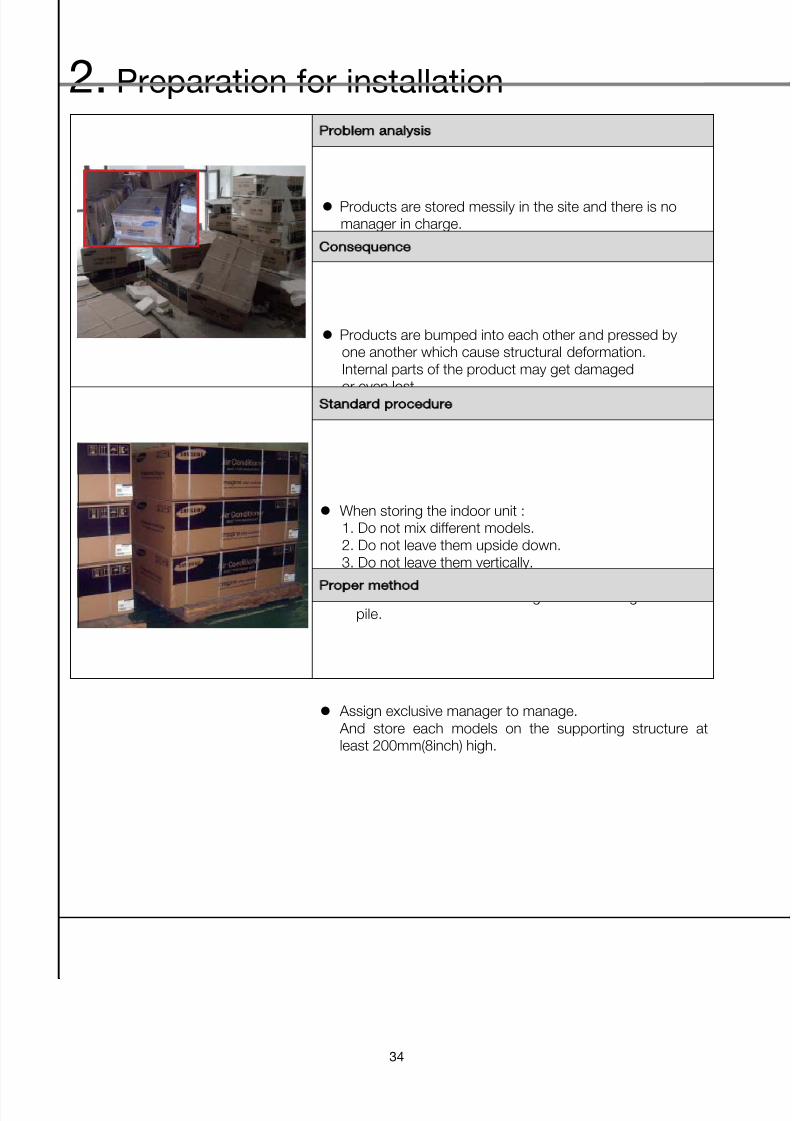
Problem analysis
Products are stored messily in the site and there is nomanager in charge.
Consequence
Products are bumped into each other and pressed byone another which cause structural deformation.Internal parts of the product may get damaged
or even lost.
Standard procedure
When storing the indoor unit :1. Do not mix different models.2. Do not leave them upside down.3. Do not leave them vertically.4. Do not tilt the indoor units.5. Do not exceed standard height when storing them in
pile.
Proper method
Assign exclusive manager to manage. And store each models on the supporting structure atleast 200mm(8inch) high.

7/24/2019 2011 DVM_Installation Guide
http://slidepdf.com/reader/full/2011-dvminstallation-guide 35/137
Installation guide
35
Problem analysis
Inappropriate product management caused outerpackaging damage.
Consequence
After damage to the outer packaging of indoor unit, dustand other foreign substances entered to the product.Furthermore, you may lose <Installation manual>, <Usermanual>, drainpipe or other parts needed forinstallation.
Standard procedure
Strictly regulate the package removal before installingthe indoor units. Manage and keep all the related partsand manuals thoroughly.
Proper method
After indoor units arrive in the site, do not remove thepackage until it is being installed. When removing thepackage upon the installation of the product, keep themanuals separately and use other accessories(such as drainpipe) properly. Take extra care to prevent from losing them.

7/24/2019 2011 DVM_Installation Guide
http://slidepdf.com/reader/full/2011-dvminstallation-guide 36/137
2. Preparation for installation
36
Problem analysis
Dust, foreign substances, rain water, industrial water anddew got inside of the indoor unit. Because it was left withall the packaging removed while installation was put onhold.
Consequence
Dust and other foreign substances will get inside andcause pipe blockage or other malfunctions.
Standard procedure
After indoor unit arrives in the site, do not remove thepackaging until it is being installed. If the installation wasstopped or put on hold for any reasons, wrap the indoorunits for protection.
Proper method
Protect the indoor unit by wrapping it.

7/24/2019 2011 DVM_Installation Guide
http://slidepdf.com/reader/full/2011-dvminstallation-guide 37/137
Installation guide
37
Problem analysis
Indoor unit, which is still in the middle of the installationprocess, is hanging on the ceiling without any protection.
Consequence
Indoor unit was hanging on the ceiling without anyProtection which allows dust and other foreign
substances to enter and cause malfunction.
Standard procedure
Wrap the indoor unit with vinyl
Proper method
Wrap the indoor unit with vinyl if the installation is still inprocess to prevent dust, foreign substances and waterfrom entering.

7/24/2019 2011 DVM_Installation Guide
http://slidepdf.com/reader/full/2011-dvminstallation-guide 38/137
2. Preparation for installation
38
Problem analysis
Safety net is not installed on 4-way cassette indoor unit.
Consequence
Safety of client and service agent can be at risk.
Standard procedure
Install the safety net for safety reasons.
Proper method
Make sure safety net is installed and let the customerknow that they must not remove them for their ownsafety.

7/24/2019 2011 DVM_Installation Guide
http://slidepdf.com/reader/full/2011-dvminstallation-guide 39/137
Installation guide
39
3. Materials and Tools
Problem analysis
R410a refrigerant system has relatively high pressure.If material does not meet the pressure-proof standards,then it may cause copper pipe explosion.
Consequence
Intensity and material specification doesn’t meet factoryrequirement and this could lead to explosion while usingthe product which could even bring personal injury.
Standard procedure
Installation material requirementMaterial : phosphorous deoxidized copper, purple
copper pipe Analysis result shows that chemical component shouldmeet the below condition (KSD 1651)Cu ≥ 99.90% ; P : 0.015%~0.040%Mechanical properties need to meet KSD 5301
Proper method
Selecting copper pipeC1220T-O(JIS) : Soft typeC1220T-1/2H(JIS) : Semi-hard type

7/24/2019 2011 DVM_Installation Guide
http://slidepdf.com/reader/full/2011-dvminstallation-guide 40/137
2. Preparation for installation
40
Problem analysis
Layer of carbon, rust and dirty foreign substances werefound on the outer surface of the copper pipe.Pipes must not have any scratches, indents or stainsetc.
Consequence
Such defects decrease the strength of the pipe whichmay result in explosion or leakage.
Standard procedure
You must select clean and dry copper pipe.Check inside of the pipe for any dust, water, indents orany signs of damage.
Proper method
Select a copper pipe according to the standards.

7/24/2019 2011 DVM_Installation Guide
http://slidepdf.com/reader/full/2011-dvminstallation-guide 41/137
Installation guide
41
Problem analysis
Due to inappropriate protection management of theinternal/external surface of the copper, large amount ofoxidation, dust and foreign substances were seen.
Consequence
R410a refrigerant is very sensitive with foreignsubstances : Mineral oil and compress oil will not solvewith each other due to different chemical characteristics. Therefore, wax type materials may clog the hole ofEEV or oil filters.
Standard procedure
Check if it is clean enough.Foreign substances in the copper pipe < 30mg/10m
R410a copper pipe must be kept clean until it isinstalled.
Proper method
Select the clean copper pipes and make sure no dust orforeign substances get into the pipe when you keep them.If the copper pipes are stored for a long period of time,clean them(blow Nitrogen) before installation to removeundesired material from inside of the pipe

7/24/2019 2011 DVM_Installation Guide
http://slidepdf.com/reader/full/2011-dvminstallation-guide 42/137
2. Preparation for installation
42
Problem analysis
After purchasing the pipe, it was not kept properly sodust, foreign substances, water and industrial water gotinside of the pipe. Also pipe was left on the ground andpeople just walked on them.
Consequence
Water or foreign substances within the pipe will causeblockage that can lead to product malfunction orperformance decrease.
Standard procedure
When storing the pipe, use cover or tape to block theentrance and do not leave them on the ground but keepthem on the supporting structure with at least 30mm inheight.
Proper method
Strictly follow the standards.

7/24/2019 2011 DVM_Installation Guide
http://slidepdf.com/reader/full/2011-dvminstallation-guide 43/137
Installation guide
43
Problem analysis
Thickness of the pipe does not meet the standards.
Consequence
Strength and the duration of the pipe will decreasewhich may cause breakup. Especially, R410a is a highpressure gas. Pipe with less thickness will have lessstrength, which may cause the pipe breakup.
Standard procedure
Required thickness – Soft typeOuter diameter(mm) Min. Thickness(mm)
Ø6.35 0.8Ø9.52 0.8Ø12.70 0.8Ø15.88 1.0
Required thickness – Semi hard type
Outer diameter(mm) Min. Thickness(mm)Ø19.05 0.9Ø22.23 0.9Ø25.40 1.0Ø28.58 1.1Ø31.75 1.1Ø38.10 1.35Ø44.45 1.6Ø50.80 2.0
Proper method
Select the pipe according to above specification

7/24/2019 2011 DVM_Installation Guide
http://slidepdf.com/reader/full/2011-dvminstallation-guide 44/137
2. Preparation for installation
44
Problem analysis
Selecting ø22.23 copper pipe, and 10mm insulation asshown in the picture.
Consequence
Low insulation effect cause large energy consumption anddecrease in system performance.
Condensation will easily form and leakage may occur
when performing heating operation in regions with hightemperature and humidity.
Standard procedure
Insulation material and quality must meet the minimumstandard thickness requirements.
Good installation will prevent condensation andguarantee air conditioning performance.
Proper method
Follow the below specification strictly and aware of theMinimum thickness requirements.
Pipe size [mm]Minimum thickness of insulation [mm]
PE foam EPDM foamØ6.35~19.05 13 10
Ø22.23~31.75 19 13Ø38.10 25 19Ø44.45~ 32 25
The thickness of insulation must be increased in case ofhigh humid conditions (over than 27°C and RH 80%) likebelow place
- Tropical / Subtropical regions or equivalent with thisregion
- The region where problems due to high temperatureand humidity are expected
- Restaurant, hot spring, sauna, basement, seaside
- Ceiling inside with high humidity due to weak ventilation

7/24/2019 2011 DVM_Installation Guide
http://slidepdf.com/reader/full/2011-dvminstallation-guide 45/137
Installation guide
45
Problem analysis
Regular vacuum pump was used in vacuum operation.
Consequence
If the power of the vacuum pump cuts off unexpectedlythen the oil gets back to the refrigerant system due topressure difference.
Standard procedure
Use the vacuum pump which is 100% dedicated forR410a system with stop valve.
Proper method
Purchase and use the vacuum pump with the stop valve.

7/24/2019 2011 DVM_Installation Guide
http://slidepdf.com/reader/full/2011-dvminstallation-guide 46/137
2. Preparation for installation
46
Problem analysis
R22 gauge was used in R410a system.
Consequence
If you use R22 gauge, remaining oil inside can generatewax type material which definitely badly affect POE oil ofR410a system, possibly clogging refrigerant passage or
causing compressor failure.
Standard procedure
Never utilize R22 gauge for R410a system to preventthe mineral oil from flowing in to the R410a system.
Use the measuring instruments that meets the standardrequirement.High pressure side : -0.1 ~ 5.3MPaLow pressure side : -0.1 ~ 3.8MPa
Proper method
Install in accordance with the standards.

7/24/2019 2011 DVM_Installation Guide
http://slidepdf.com/reader/full/2011-dvminstallation-guide 47/137
Installation guide
47
1. Sleeve work
1-1. Positioning of the pipe holes
1) The drilling holes for the drain piping should be positioned such that the pipes have a downwardgradient. (The gradient must be at least 1/100. The thickness of the insulation materials must alsobe taken into consideration.)
2) The diameter of the drilling holes for the refrigerant piping should include allowance for thethickness of the insulation materials.
3) Attention should be paid to the construction of the beam themselves since there are sometimesparts of the beam which cannot be used to accommodate drilling holes.
1-2. Selection of sleeve
1) Sleeve work should be performed to make a space for passing pipe and wire through the wall orground under construction
2) Use of shielded transmission cable is recommended to avoid the problem of electrical noise
3) Depending on the selected product or the installation environment, if the insulation material’s
thickness is subject to change, then additional calculations are necessary.Sleeve diameter [mm] = (Liquid pipe diameter+ insulation material thickness x2) + (Gas pipediameter + insulation material thickness x2) +20
4) Maintain a minimum separation of 10mm between the pipes to facilitate smooth air flows.
(To prevent dew forming)
3. Guideline for each installation process

7/24/2019 2011 DVM_Installation Guide
http://slidepdf.com/reader/full/2011-dvminstallation-guide 48/137
3. Guideline for each installation process
48
Selection of the refrigerant pipe sleeve’s diameter (a)
ClassificationLiquid pipe diameter(mm)
6.35 9.52 12.7 15.88 19.05 22.22Gas pipediameter
(mm)
Gas pipe diameter +Insulation (based on 19t)
Insulation(Based on 9t)
Insulation(Based on 13t)
24.35 27.52 38.7 41.88 45.05 48.22
6.35 32.35 77 80 91 94 97 101
9.52 47.52 92 95 106 109 113 116
12.7 50.7 95 98 109 113 116 119
15.88 53.88 98 101 113 116 119 122
19.05 57.05 101 105 116 119 122 125
22.22 60.22 105 108 119 122 125 128
25.4 63.4 108 111 122 125 128 13228.58 66.58 111 114 125 128 132 135
31.75 69.75 114 117 128 132 135 138
38.1 76.1 120 124 135 138 141 144
44.45 82.45 127 130 141 144 148 151
※ If the insulation material’s thickness is subject to change depending on the installation location,
you must reselect a new sleeve pipe diameter.

7/24/2019 2011 DVM_Installation Guide
http://slidepdf.com/reader/full/2011-dvminstallation-guide 49/137
Installation guide
49
2. Insert work and support work
2-1. Insert work
Example : Drilling holes in a reinforced concrete beam
Full thread bolt works

7/24/2019 2011 DVM_Installation Guide
http://slidepdf.com/reader/full/2011-dvminstallation-guide 50/137
3. Guideline for each installation process
50
2-2. Support work
1) Installation guideline for a vertical piping
▶ Down-stopper fixing guide
Height Fixing interval Remarks
1 lowerFix a pipe every
5m(16.5ft)
If there is a pit,fix a pipe at each
floor
2Higher than
15m
Install a downstopper every3floor or every
15m height
Pipe must befixed at every 5m
※ How to fix a pipe
- Utilize “U” shape volt or circular band on the insulation of the pipe
Fixing with a circular band Fixing with a Down-stopper
2) Down-stopper installation
① Attaching the Down-stopper ② Brazing work ③ Assembly of wall contact part
to the vertical pipe
⑤ Finished sample ④ Insulating a pipe Assembled sample
Attaching the down stopper to the
vertical pipe
Heat uniformly until a base metalbecome cherry red in color than
apply a filter metal
Tightly wrap the insulation with a
finishing tape

7/24/2019 2011 DVM_Installation Guide
http://slidepdf.com/reader/full/2011-dvminstallation-guide 51/137
Installation guide
51
3. Concealed Box work
3-1. Concealed Box work
1) Objectives
- The concealed box aims at enhancing the interior inside the building by burying the drains,the copper pipes, the insulation materials, and the wires in the earlier phase, when you need toinstall an indoor unit
2) Functions
(1) Buried in the wall on the pipe installation site and connecting the pipes, the drains and the wires.
(2) Copper pipe protection, enhancing the exterior.
(3) Mounting a pressure gauge to check the air tightness at any time.
Concealed box Buried box connection board

7/24/2019 2011 DVM_Installation Guide
http://slidepdf.com/reader/full/2011-dvminstallation-guide 52/137
3. Guideline for each installation process
52
4. Refrigerant pipe construction
4-1. Drawing review1) Compare the actual site with the drawing. When installing the refrigerant pipes, check interferences
and the requirements for each pipe diameter size/length/quantity ahead of time.
Temper grade and minimum thickness of the refrigerant pipe
Outer diameter Minimum thickness Temper grade
6.35 0.7
C1220T-O
9.52 0.7
12.70 0.8
15.88 1.0
19.05 0.9
C1220T-1/2HOr
C1220T-H
22.23 0.9
25.40 1.0
28.58 1.1
31.75 1.1
38.10 1.35
44.45 1.6
50.80 2.0
(1) Soft or hard pipes (Annealed, Drawn temper)
Make sure to use C1220T-1/2H(Semi-hard) pipe for more than ∮19.05mm.
In case of using C1220T-O (soft) pipe for ∮19.05mm, pipe may be broken,
which can result in an inur .
Cautions

7/24/2019 2011 DVM_Installation Guide
http://slidepdf.com/reader/full/2011-dvminstallation-guide 53/137
Installation guide
53
2) Preparing a pipe
(1) On the drawing, check the pipe diameter/length and the insulation material’s thickness andlength. Prepare some margins for the dimension shown in the drawing (to give elastic tensions),Use a special cutter to cut the pipes.
3) Check the quantities of the branch pipe/header and the outdoor unit’s branch pipes.(1) Additionally purchased items
Type Model Total capacity
Y-joint
MXJ-YA1509* 15.0kW below
MXJ-YA2512* 15.0~40.6kW
MXJ-YA2812* 40.6~46.4 kW
MXJ-YA2815* 46.4~69.6 kW
MXJ-YA3119* 69.6~98.6 kW
MXJ-YA3819* 98.6~139.2 kW
MXJ-YA4422* 139.2 kW and over
Y-joint
(Only for DVM plus Ⅲ HR module)
MXJ-YA1500* 23.2kW and belowMXJ-YA2500* 23.2~69.6 kW
MXJ-YA3100* 69.6~139.2 kW
MXJ-YA3800* 139.2 kW and over
Header Joint
MXJ-HA2512* 46.4kW and below(For 4 rooms)
MXJ-HA3115* 69.6kW(For 8 rooms)
MXJ-HA3819* 69.6kW and over (For 8 rooms)
Outdoor JointMXJ-T3819* 48HP and below
MXJ-T4422* 50HP and over
Outdoor Joint
(Only for DVM plus Ⅲ HR module)
MXJ-T3100* 48HP and below
MXJ-T3800* 50HP and over

7/24/2019 2011 DVM_Installation Guide
http://slidepdf.com/reader/full/2011-dvminstallation-guide 54/137
3. Guideline for each installation process
54
4-2. Pipe Cutting
1) Burring
- When performing burring works, point the pipe face downward to prevent entry of burr.
2) Taping
– To prevent entry of moisture or dust, seal off the pipe completely.

7/24/2019 2011 DVM_Installation Guide
http://slidepdf.com/reader/full/2011-dvminstallation-guide 55/137
Installation guide
55
Covering is an extremely important operation as it prevents water, dirt or dust from getting
inside the pipes.
Moisture inside the pipes was a constant source of trouble in the past. Theutmost care is required to nip this problem in the bud.
The end of each pieces of pipe must be covered. “Pinching” is the most effective method but“taping” is an simple alternative which may be used according to the work area and term of work.
Location Term of Work Covering Method
Outdoors1 months or more Pinching
Less than 1 months Pinching or taping
Indoors Irrelevant Pinching or taping
① Pinching method The end of the copper pipe is squeezed together and the gap brazed.
② Taping method The end of the copper pipe is covered with PVC tape (vinyl tape).
<Taping method>
Particular care should be taken during the following operations:When passing copper pipe through a penetration hole (Dirt easily gets into the pipe).When copper pipe is located outside (Rainwater gets in)(Special care is needed when the pipes are standing vertically outside)
7/24/2019 2011 DVM_Installation Guide
http://slidepdf.com/reader/full/2011-dvminstallation-guide 56/137
3. Guideline for each installation process
56
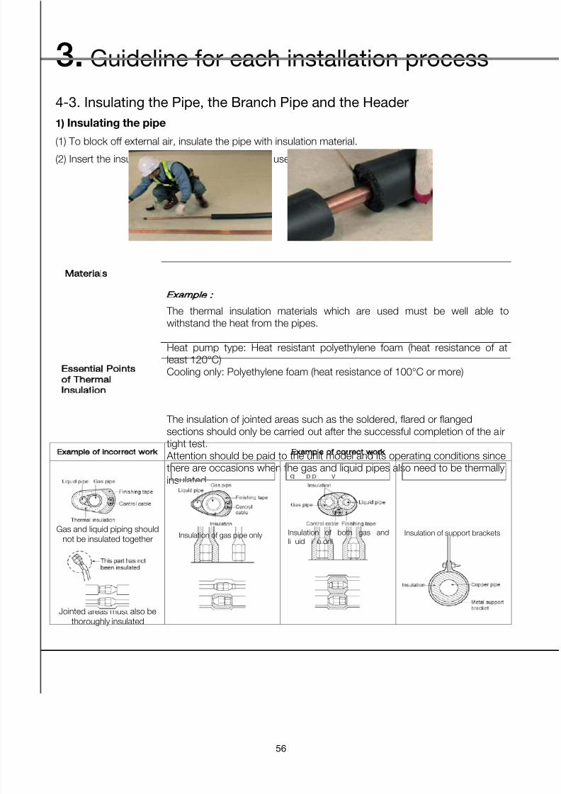
4-3. Insulating the Pipe, the Branch Pipe and the Header
1) Insulating the pipe
(1) To block off external air, insulate the pipe with insulation material.
(2) Insert the insulation material into the pipe and use a special EPDM glue to finish it.
Materials
The thermal insulation materials which are used must be well able towithstand the heat from the pipes.Example :
Heat pump type: Heat resistant polyethylene foam (heat resistance of atleast 120°C)Cooling only: Polyethylene foam (heat resistance of 100°C or more)
Essential Points
of Thermal
Insulation
The insulation of jointed areas such as the soldered, flared or flangedsections should only be carried out after the successful completion of the airtight test. Attention should be paid to the unit model and its operating conditions sincethere are occasions when the gas and liquid pipes also need to be thermallyinsulated.
Example of incorrect work Example of correct work
Gas and liquid piping shouldnot be insulated together
Jointed areas must also bethoroughly insulated
Insulation of gas pipe only Insulation of both gas andli uid i e onl
Insulation of support brackets

7/24/2019 2011 DVM_Installation Guide
http://slidepdf.com/reader/full/2011-dvminstallation-guide 57/137
Installation guide
57
▶ Important points
① The thickness of the thermal insulation material must be determined in the light of the pipesizes. Pipe size in. (mm) Thickness of insulation material
Pipe size in(mm) Thickness of insulation material
1/4~1 (6.4mm~25.4mm) 1/2 or more (12.5mm or more)
② It will be necessary to increase the values in the above table for top floors or where conditionsare hot and humid. (Refer to Installation manual "6-5 Pipe insulation" for more detail)
③ Where a customer supplies his own specifications then these must be adhered to.
④ Where it is anticipated that the air conditioning unit will be operated at external airtemperatures of 10°C or less then thermal insulation will also be required for the liquid pipes.
Heat Recovery
Series
Suction, Discharge Gas piping, liquid piping must be insulated.Example of thermal insulation work.
3 piping section (between outdoor unit and MCU unit) 2 piping section (between MCU unit and indoor unit)
If you think that the humidity around the cooling piping might exceed 86°Fand RH80%, reinforce the insulation on the cooling piping (at least 13/16"thick). Condensation might form on the surface of the insulation.
2) Insulating the refrigerant pipe
(1) Insulating the refrigerant You must check if there is a gas leak before completing all the installation process.Use EPDM insulation which meets the following condition.
Item Unit Standard
Density g/cm3 0.048~0.096
Dimension change route by heat % -5 or less
Water absorption rate g/cm3 0.005 or less
Thermal conductivity kcal/m·h·˚C 0.032 or less
Moisture transpiration factor ng/(m²·s·Pa) 15 or less
Moisture transpiration grade g/(m²·24h) 15 or less
Formaldehyde dispersion mg/L -
Oxygen rate % 25 or less

7/24/2019 2011 DVM_Installation Guide
http://slidepdf.com/reader/full/2011-dvminstallation-guide 58/137
3. Guideline for each installation process
58
(2) Selecting the insulation of the refrigerant pipeInsulate the gas side and liquid side pipe referring to the thickness according to the pipe size. The thickness according to the pipe size is calculated at the indoor temperature of 27°C and
humidity of 80%. If installing in an unfavorable conditions from it, use thicker one.
Pipe size (mm)
Minimum thickness
of insulation (mm) Remarks
PE foam EPDM foam
ø6.35~19.05 13 10 If you install the pipeunderground, at the seaside,a spa or on the lake, use thickerone according tothe pipe size.
ø22.23~31.75 19 13
ø38.10 25 19
- 32 25
(3) Insulating the refrigerant pipe
Be sure to insulate the refrigerant pipe, joints and connections with class ‘o’ material.If you insulate the pipes, the condensed water does not fall from the pipes and the capacity
of the air conditioner is improved.Check if there are any insulation cracks on the bent pipe.
Pipe insulation Pipe insulation after insulating EEV kit
• Insulation of the gas and liquid pipes can bein contact with each other but they shouldnot be pressing each other.
• When contacting the gas side and liquid sidepipe, use thicker insulation.
• When installing the gas side and liquid sidepipes, leave 10mm of space.
• When contacting the gas side and liquid sidepipe, use thicker insulation.
Insulating the refrigerant pipe
• Install the insulation not to be get wider anduse the adhesives on the connection part of itto prevent moisture entering.
• Wind the refrigerant pipe with insulation tape ifit is exposed to outside sunlight.
• Install the refrigerant pipe respecting that theinsulation does not get thinner on the bent part
or hanger of pipe.
Cautions

7/24/2019 2011 DVM_Installation Guide
http://slidepdf.com/reader/full/2011-dvminstallation-guide 59/137
Installation guide
59
(4) Insulating the branch joint
Y-joint liquid side of the outdoor unit
Attach the insulation provided with a branch joint to the insulation purchased individually
without a gap. Wrap the connected part with an insulation (purchased in the market) of athickness of at least 10mm.Use an insulation that should be able to handle the interior temperature over 120°C.Wrap the branch joint with an insulation of a thickness of at least 10mm.
Header joint
Fasten the header joint using a cable tie and cover the connected part.Insulate the header joint and the brazed part and wrap the connected part with an adhesive
insulation tape to prevent it from defrosting.Before starting the insulation work on joints(brazed part), ensure that the e)pressure test is
done (no leakage)
.
Fix the header joint after insulating it.

7/24/2019 2011 DVM_Installation Guide
http://slidepdf.com/reader/full/2011-dvminstallation-guide 60/137
3. Guideline for each installation process
60
4-4. Mounting the Pipe, the Branch Pipe and the Header
1) Mounting the insulated pipes.
– The liquid/gas pipes should be mounted at the different position horizontally in order not tointerfere with each other.
2) Install a hanger before and behind the branch pipe.- Install a hanger before and behind the branch pipe.

7/24/2019 2011 DVM_Installation Guide
http://slidepdf.com/reader/full/2011-dvminstallation-guide 61/137
Installation guide
61
3) When installing the branch pipe, pay attention to the following cautionary items.
Model
Name
MXJ-HA2512 MXJ-HA3115 MXJ-HA3819
Liquid side
Gas side
Insulation(Liquid side/Gas side)
Socket
LiquidSide
Gas side
Horizontallyinstalled
Verticallyinstalled
Install the Y-joint within ±15° on
the horizontal or on the vertical.

7/24/2019 2011 DVM_Installation Guide
http://slidepdf.com/reader/full/2011-dvminstallation-guide 62/137
3. Guideline for each installation process
62
Header joint
① Select the reducer fitted on the diameter of the pipe.
② Braze the pipes ends with caps if the number of connected indoor unit is fewer than header joint ports.
< Liquid side > < Gas side >
• When using A~J type of header joint, connect the header joint tothe pipe with provided reducer.
• When using K~Z type of header joint, connect the header joint tothe pipe by cutting the provided reducer properly.
• Connect the header joint in order respecting the number of the indoor unit.• Connect the indoor unit as the highest capacity comes first.
③ Install the header joint horizontally.
- Install the header joint horizontally so that it is not facing down.
< Liquid side > < Gas side >
Incorrect installation of Y-joint and header joint cause poor oil and refrigerant distribution
between indoor units.It may decrease the system’s performance or cause compressor failure.
Note
Cautions

7/24/2019 2011 DVM_Installation Guide
http://slidepdf.com/reader/full/2011-dvminstallation-guide 63/137
Installation guide
63
4) Installing the branch joints
Outdoor joint
Installation of outdoor joint
Use the attached reducer properly according to the selected pipe size.
<Liquied pipe >
<Gas pipe, High pressure gas pipe>
• When using A~J type of Outdoor joint, connect the Outdoor joint to the pipe with
provided reducer.
• When using K~Z type of Outdoor joint, connect the Outdoor joint to the pipe by
cutting provided reducer properly.
Note

7/24/2019 2011 DVM_Installation Guide
http://slidepdf.com/reader/full/2011-dvminstallation-guide 64/137
3. Guideline for each installation process
64
4-5. Connecting the Pipe/Branch Pipe
1) Reducer mounting
- When connecting the pipes/branch pipes, you need a reducer to compensate for the diameterdifferences. The following specs are applied.
Y-Joint
Model
Name MXJ-YA1509
MXJ-YA2212
MXJ-YA2512
MXJ-YA2815
MXJ-YA3119
MXJ-YA3819
Liquid side
Gas side
Insulation
(Liquid side/Gas
side)
Socket
Liquid
Side
Gas side
2) Reducer mounting methods
- If the pipe is inserted deep into the reducer, it can cause refrigerant noises, so be careful.

7/24/2019 2011 DVM_Installation Guide
http://slidepdf.com/reader/full/2011-dvminstallation-guide 65/137
Installation guide
65
4-6. Installing the Branch Pipe for the Outdoor Unit
1) Connecting the outdoor unit pipe
Heat Pump
Connection from front side
Connection from bottom at the
left/right side Working process
Workingprocess
• First, remove the cover from unit.• Separate the knock-out hole to use. If
the hole is open, small animals suchas squirrels and rats may get into theunit through the hole and the unit maybe damaged.
• Fix the pipe cover of bottom side andfix the pipe cover of upper sidethereafter.
• Separate the knock-out hole at thebottom side of the unit and install thepipe.
• After installing and insulating the pipe,close up the remaining gap. If the gapis remain open, small animals such asrats and squirrels may get inside theunit and cause damage to the unit.
Single
Installation
Combinationinstallation
7/24/2019 2011 DVM_Installation Guide
http://slidepdf.com/reader/full/2011-dvminstallation-guide 66/137
3. Guideline for each installation process
66
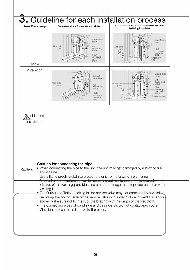
Heat Recovery
Connection from front side
Connection from bottom at the
left/right side
Single
Installation
Combination
installation
Caution for connecting the pipe
• When connecting the pipe to the unit, the unit may get damaged by a brazing fireand a flame.Use a flame proofing cloth to protect the unit from a brazing fire or flame. Ambient air temperature sensor for detecting outside temperature is located on theleft side of the welding part. Make sure not to damage the temperature sensor when
welding it.• The O-ring and Teflon packing inside service valve may get damaged by a welding
fire. Wrap the bottom side of the service valve with a wet cloth and weld it as shownabove. Make sure not to interrupt the brazing with the drops of the wet cloth.
• The connecting pipes of liquid side and gas side should not contact each other. Vibration may cause a damage to the pipes.
Cautions

7/24/2019 2011 DVM_Installation Guide
http://slidepdf.com/reader/full/2011-dvminstallation-guide 67/137
Installation guide
67
2) Piping works among outdoor units
The additional branch joints are needed for module installation of the outdoor units.When outdoor units are installed in module, there is no designation of outdoor unit’s locationaccording to capacity. The connected piping should be positioned at the same or lower level with pipe cover hole.
Cautions Correct piping work Wrong piping work
The refrigerantpiping should bethe same level orlower thanconnecting position
of piping to outdoorunits.
Piping work shouldbe run with sidedirection for betteruniform distributionof refrigerant and oillike next diagram.
Outdoor joint kitsshould be installedin a horizontaldirection even it is alow pressure pipe.
When the pipinglength betweenoutdoor and branch joints is 2m ormore, a vertical traphas to be installedlike right diagram.

7/24/2019 2011 DVM_Installation Guide
http://slidepdf.com/reader/full/2011-dvminstallation-guide 68/137
3. Guideline for each installation process
68
4-7. Brazing
1) Nitrogen substituted welding
(1) Perform nitrogen substituted brazing works.
Brazing the pipe
Make sure that there is no moisture inside the pipe.Make sure that there are no foreign materials and impurities in the pipe.Make sure that there is no leak.Make sure to follow the instruction when brazing the pipe.
The use of Nitrogen gas
① Use Nitrogen gas when brazing the pipes as shown
in the picture.②
If you do not use Nitrogen gas when brazing the
pipes, oxide may form inside the pipe. It can causethe damage of the compressor, valves.
③ Adjust the flow rate of the Nitrogen gas with a
pressure regulator to maintain 0.05m3/h or less.
Direction of the pipe when brazing
Performing the brazing of the pipe should be headed downward or horizontally.
Note Avoid brazing the pipe upward.
Nitrogen substitution for prevention of copper pipe corrosions

7/24/2019 2011 DVM_Installation Guide
http://slidepdf.com/reader/full/2011-dvminstallation-guide 69/137
Installation guide
69
2) Comparison with a case without nitrogen substitution
With Nitrogen substitution Without Nitrogen substitution
3) Be cautious for pipe-to-pipe brazing works
Brazing work should be carried out either downwards or sideways. An upward direction should be avoided.
CAUTION
1. Generally expending pipe brazing is performed with pan-coil type copper pipe, andsocket blazing is performed with straight copper pipe.
2. Do not perform flare part brazing or butt-brazing.3. Brazing should be performed on welding table.4. No dust should enter in the pipe while brazing.
5. Distance of copper pipe support spacing is within 1~2m.6. The copper pipe should not be secured directly by metal brackets.

7/24/2019 2011 DVM_Installation Guide
http://slidepdf.com/reader/full/2011-dvminstallation-guide 70/137
3. Guideline for each installation process
70
4-8. Nitrogen Pressurization Test
1) Leakage test
Perform individual finishing of the liquid/gas pipe or connect the liquid/gas pipes for pinching andbrazing.
Air tightness test
Nitrogen pressurization, 4MPa
No change in the gauge for 24 hours 41kgf/cm2(4.1Mpa)pressure maintained
Maintains 4Mpa for 24 hours. If no leakage, then pressure down to 1MPa.
Maintain 1Mpa until connecting the outdoor/indoor units. Prevent corrosion in the copper pipes.
Maintain a pressure of 10kgf/cm2 (1Mpa)

7/24/2019 2011 DVM_Installation Guide
http://slidepdf.com/reader/full/2011-dvminstallation-guide 71/137
Installation guide
71
5. Refrigerant pipe flushing
[3 major effects]
(1) Removal of oxidation bubbles formed inside copper pipes when “nitrogen replacement isinsufficient” during brazing work
(2) Removal of extraneous material and moisture from pipes when covering has been insufficient(3) Check connection in pipes linking outdoor and indoor units (Both liquid and gas pipes)
[Example of procedure]
(1) Set pressure regulator on nitrogen cylinder.∗ The gas used must be nitrogen.
(There is a danger of condensation if fleon or carbon dioxide are used and oxygen carries therisk of explosions.)
(2) Connect the charge hose from the pressure regulator to the service port on the liquid pipe sideof the outdoor unit.
(3) Fit blanking plugs to all indoor units (B) other than unit A.
(4) Open the main valve on the nitrogen cylinder and set the pressure regulator to 72 psi.
Flushing is a method of cleaning extraneous matter out of pipes using pressurized gas.

7/24/2019 2011 DVM_Installation Guide
http://slidepdf.com/reader/full/2011-dvminstallation-guide 72/137
3. Guideline for each installation process
72
(5) Check that the nitrogen is passing through the unit A liquid pipe.
(6) Flushing.
① Block the end of the pipe with the insulation of your hand.↓
② When the gas pressure becomes too great to contain remove insulation quickly. (First flush)↓
③ Block the end of the pipe with insulation again.↓
(Carry out second flushing)
(The nature and amount of the extraneous material inside the pipe can be checked during flushingby placing a rag lightly over the end of the pipe. In the unlikely case that even a small quantity of
moisture is found then the inside of the pipe should be dried out thoroughly.)
Action:
① Flush the inside of the pipe with nitrogen gas. (Until such time as the moisture disappears.)
② Carry out a thorough vacuum drying operation. (See page 34)
- Close the main valve on the nitrogen cylinder.
-Repeat the above operation for unit B.
-When the liquid pipe operations have been completed then do the same with the gas pipes.

7/24/2019 2011 DVM_Installation Guide
http://slidepdf.com/reader/full/2011-dvminstallation-guide 73/137
Installation guide
73
6. Drainpipe Work
6-1. Diagram Review
1) On the diagram check the locations of the horizontal, branch and vertical pipes.
(1) What is a horizontal pipe?
It is a drainpipe where the drainpipes from the indoor unit are merged.
(2) What is a branch pipe?
It is a drainpipe from an indoor unit to a horizontal pipe..
(3) What is a vertical pipe?
It is a vertical drainpipe that a horizontal pipe is connected for drain purpose.

7/24/2019 2011 DVM_Installation Guide
http://slidepdf.com/reader/full/2011-dvminstallation-guide 74/137
3. Guideline for each installation process
74
2) On the diagram, check the location of the hanger for the drainpipe.
(1) Due to the weight of the drainpipe and the condensed water, it can cause bending. The hangers
should be separated by 1 to 1.5 meters.
3) Check the drainpipe diameter (horizontal, branch, vertical pipe) on the diagram.
4) Review installation of a horizontal pipe first.
Install a branch pipe after installing an indoor unit. (Since the drainpipe location and directioncould be changed.)

7/24/2019 2011 DVM_Installation Guide
http://slidepdf.com/reader/full/2011-dvminstallation-guide 75/137
Installation guide
75
6-2. Drainpipe Cutting and Insulation
1) Cut the drainpipe as its dimension and size are shown in the diagram.
Use a specialized cutter for drainpipe
2) Use a special cutter for the PVC pipes. A PVC pipe cutter is shown in the following.
(PVC pipe cutter photo)
3) Insulate the drainpipe that is cut. (Thickness of 5~10T, attach a photo of inserted
insulation materials)
Inserting the drainpipe insulation material
(1) The drainpipe insulation materials should be non-flammable.
(2) Recommended insulation thickness is 5~10T and select the desirable insulation thicknessaccording to the humidity/temperature of the ceiling.

7/24/2019 2011 DVM_Installation Guide
http://slidepdf.com/reader/full/2011-dvminstallation-guide 76/137
3. Guideline for each installation process
76
6-3. Mounting the Drainpipes
1) Mount a horizontal pipe in the hanger.
Cutting and mounting the drainpipe
2) Perform 1/100 slope works on the horizontal pipe in the direction of the vertical
pipe. (Discharge the condensed water.)
Checking the slope 1/100 or more downward slope

7/24/2019 2011 DVM_Installation Guide
http://slidepdf.com/reader/full/2011-dvminstallation-guide 77/137
Installation guide
77
6-4. Connecting the Drainpipe
1) At the area where the branch pipe is connected to the horizontal pipe, use a T-
joint to make connections between the horizontal pipe & branch pipe.
2) A T-joint should be faced upward.
Precaution: T-joints should not be connected horizontally.
3) When you connect the horizontal pipe to the vertical pipe, do not make horizontal
connections.
Because the condensed water flowing from the upper area of the vertical pipe can back-flow intothe horizontal pipe.
No horizontal connection from the horizontal pipe to the vertical pipe

7/24/2019 2011 DVM_Installation Guide
http://slidepdf.com/reader/full/2011-dvminstallation-guide 78/137
3. Guideline for each installation process
78
4) Branch pipe (indoor unit – horizontal pipe) construction method
(1) Indoor unit with a drain pump
① The pipe coming from the indoor unit should have a trap to prevent reverse flows.
② The max height from the indoor unit’s drainpipe exit to the trap ranges from 300 to 550mm.
③ In the upper area of the trap (max height of the drainpipe), install an air vent to prevent thecondensed water’s back flows into the drainpipe caused by an increase in the pressure inthe drainpipe.
④ The end of the air-vent should form a T or 7 shape to prevent entry of dust or foreignsubstances.
Check for leakages after 24 hours. Installing the air-vent
⑤

7/24/2019 2011 DVM_Installation Guide
http://slidepdf.com/reader/full/2011-dvminstallation-guide 79/137
Installation guide
79
(2) Indoor unit without a drain pump
① Form a reverse flow prevention P or U-trap on the pipe coming from the indoor unit.
P-Trap, U-Trap pipe photo inserted here.
② An air-vent should be installed on the indoor unit side and located higher than the drainpipeheight.
③ Or, install an air vent on the vertical pipe.

7/24/2019 2011 DVM_Installation Guide
http://slidepdf.com/reader/full/2011-dvminstallation-guide 80/137
3. Guideline for each installation process
80
6-5. Drainpipe Combination and Bonding
1) Apply PVC glue to the joint area and wait for one to two minutes before combining them.
6-6. Drainpipe Water Soaking Test
1) Pour the water through the uppermost drainpipe or an air vent to check if the waterflows smoothly. After that, for twenty-four hours, perform water soaking test to testleakages. In this test, the amount of water injection should be same as the amount ofwater discharge.
2) In the winter, use anti-freezing liquid instead of water.
3) If the water discharge is not smooth, recheck the tilt of the drainpipe.
Drain water soaking test
Check for leakages after 24 hours
Check for leakages after 24 hours.

7/24/2019 2011 DVM_Installation Guide
http://slidepdf.com/reader/full/2011-dvminstallation-guide 81/137
Installation guide
81
6-7. Insulation Material Finishing
1) In a water soaking test, if there is no leakage, then insulate the bonded areas.
Insulating bonded/joint area of Drainpipe
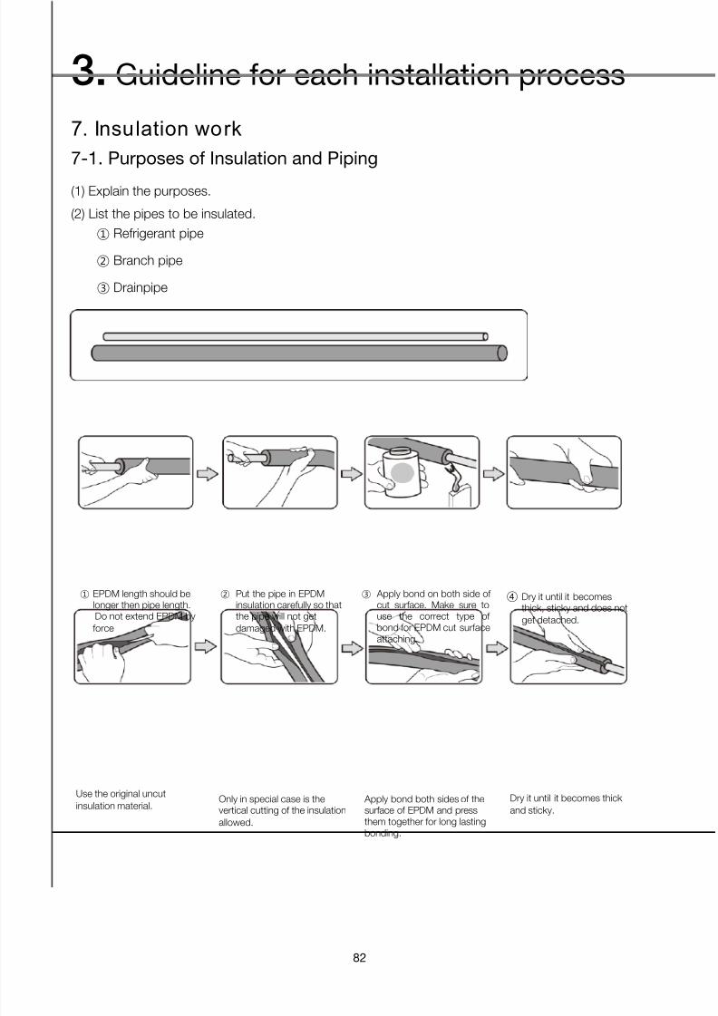
7/24/2019 2011 DVM_Installation Guide
http://slidepdf.com/reader/full/2011-dvminstallation-guide 82/137
3. Guideline for each installation process
82
7. Insulation work
7-1. Purposes of Insulation and Piping
(1) Explain the purposes.
(2) List the pipes to be insulated.
① Refrigerant pipe
② Branch pipe
③ Drainpipe
7-2. Insulation Method (Procedure)
① Operational steps
② Bending vertical side of insulation
① EPDM length should belonger then pipe length.Do not extend EPDM byforce
② Put the pipe in EPDMinsulation carefully so thatthe pipe will not getdamaged with EPDM.
③ Apply bond on both side ofcut surface. Make sure touse the correct type ofbond for EPDM cut surfaceattaching.
④
Dry it until it becomesthick, sticky and does notget detached.
Use the original uncut
insulation material. Only in special case is thevertical cutting of the insulation
allowed.
Apply bond both sides of thesurface of EPDM and pressthem together for long lastingbonding.
Dry it until it becomes thick
and sticky.

7/24/2019 2011 DVM_Installation Guide
http://slidepdf.com/reader/full/2011-dvminstallation-guide 83/137
Installation guide
83
③ ‘L’ Fitting connection part insulation
① Insertion type: general insulation method② Partitioning: Vertical insertion type
③ Elbow & edge area insulation methods
All of the fitting connecting partsshould be insulated.Bring face to face the each endof EPDM on fitting connectionpart.
Make fitting cover to fit theEPDM insulation. Fitting covershould be overlapped with
insulation min 1inch(2.5m).
Bond the both cutting sides offitting cover.

7/24/2019 2011 DVM_Installation Guide
http://slidepdf.com/reader/full/2011-dvminstallation-guide 84/137
3. Guideline for each installation process
84
8. Gas leak test
8-1. Purposes
1) Leakage test step
(1) 1st leakage test: After installing the pipe and the branch pipe, use Nitrogen at 4Mpa for testing. →
Maintain 1Mpa.
(2) 2nd leakage test: After connecting the pipe to the outdoor/indoor unit, use Nitrogen at 4Mpa for
testing.
2) Detect leakages that can occur while connecting the pipe to the outdoor/indoor units.
3) 1
st
leakage test is completed, so now proceed with the 2
nd
leakage test.

7/24/2019 2011 DVM_Installation Guide
http://slidepdf.com/reader/full/2011-dvminstallation-guide 85/137
Installation guide
85
8-2. Procedures (HR Module Installation Standard)
1) Before starting
(1) Check if all the service valves are closed (liquid, gas, high pressure gas, Oil Equalizing pipes).
(2) When using a nitrogen charging container, install pressure control regulator.
(3) R410a gauge manifold – minimum 4 units, manifold hoses – five units or more.
2) The following pipes should pass a leakage test.
(1) Liquid pipe
(2) Gas pipe
(3) High-pressure gas pipe
(4) Oil Equalizing pipe
3) Connect the prepared two manifold gauges and five hoses as shown below and
connect to each service valve.
(1) If due to the shortage of manifold gauge, you can’t test all the equal oil pipes at the same time,
then first test the three main pipes and perform final tests.
4 ) Pressure up the inner area of the pipe to 4.1MPa for a leakage test and maintain
the pressure for 24 hours.
5) If there is no leakage for 24 hours, then depressurize to 1Mpa and maintain the
pressure. The reason is to prevent corrosion in the pipes.

7/24/2019 2011 DVM_Installation Guide
http://slidepdf.com/reader/full/2011-dvminstallation-guide 86/137
3. Guideline for each installation process
86
9. Vacuum drying
9-1. Purposes
Using vacuum drying, the moisture inside the product or pipe can be evaporated.
9-2. Procedure (HR Modulation Installation Standard)
1) Before starting
(1) Check if the second air tight test (outdoor unit, MCU, indoor unit pipes are all connected.).
(2) After the second air tight test, check if the pressure is down to 1Mpa and check if there is anyleakage of nitrogen gas.
(3) Minimum two sets of R410a gauge manifolds, five or more manifold hoses, more than one vacuum
pump.(4) Power up the indoor/outdoor unit. In case of HR, if the power is not on, then all the valves inside
the MCU are closed. So the vacuum may not be achieved by using the S/V of the outdoor unit.
2) Connect the gauge manifold to achieve a vacuum for the following pipes.
(1) Liquid pipe
(2) Gas pipe
(3) High-pressure gas pipe
(4) Oil Equalizing pipe
(If the manifold can’t achieve a perfect vacuum, then purge it with refrigerants.)
3 ) Connect the prepared two manifold gauges and five hoses as shown below and
connect to each service valve.

7/24/2019 2011 DVM_Installation Guide
http://slidepdf.com/reader/full/2011-dvminstallation-guide 87/137
Installation guide
87
(1) Connect a hose to the liquid/gas/high pressure gas pipes and make the vacuum with a vacuumpump.
(2) The equal oil pipe has gas type of refrigerants. Purge oxygen inside the equal oil pipe.
(3) Compare the external temperature with the temperature below. Keep the vacuum until the gaugepressure reaches the value in the below table. (For more than 2-and–a-half hours)
Boiling point
of water(℃)
Gauge pressure
mmHg Pa Torr
40 -705 7333 55
30 -724 4800 36
26.7 -735 3333 25
24.4 -738 3066 22
22.2 -740 2668 20
20.6 -742 240 1817.8 -745 2000 15
15.0 -747 1733 13
11.7 -750 1333 10
7.2 -752 1066 8
0 -755 667 5
Have been achieved in the vacuum drying operation
(4) After making the vacuum, check if the gauge pressure has changed. If no change is found, thenmove to the additional refrigerant charging phase.

7/24/2019 2011 DVM_Installation Guide
http://slidepdf.com/reader/full/2011-dvminstallation-guide 88/137
3. Guideline for each installation process
88
10. Charging Refrigerant
10-1. Purposes
Add an additional amount of refrigerant for the installed pipe length to guarantee product performanceand reliability.
The additional amount of refrigerant varies depending on the product, the liquid pipe diameter and soon, so you must check the installation manual before proceeding.
10-2. Procedures (HR Module Installation Standards)
1) Before starting
(1) Check the necessary amount of additional refrigerant injection depending on the liquid pipe
diameter.
(2) Check the liquid pipe length for the system.
(3) Based on the above value, calculate the additional amount of refrigerant.
(4) Prepare an electronic scale and refrigerants.
2) As shown below, prepare a gauge manifold, a refrigerant box and an electronic scale.

7/24/2019 2011 DVM_Installation Guide
http://slidepdf.com/reader/full/2011-dvminstallation-guide 89/137
Installation guide
89
(1) Connect a refrigerant box to the manifold gauge.
(2) Since oxygen exists in the hose between the gauge manifold and the refrigerant box, open therefrigerant box valve to purge oxygen from the hose.
(3) Place the refrigerant box on top of the electronic scale.
(4) If it is a commercial product (sales with 11kg), then turn the refrigerant box upside down to place iton top of the electronic scale. If the refrigerant box type is chargeable (multiple use), then you don’tneed to turn it upside down as long as the gauge manifold is connected to the liquid valve of therefrigerant box. If not connected, then turn it upside down before placing it on the electronic scale.
The reason is because you want to injectliquid
refrigerants.
3) Inject the amount of refrigerant calculated above.
(1) Open the gauge manifold and check the amount of refrigerant injection.(2) If entire refrigerant flows in smoothly, then turn off the valve and separate the gauge manifold from
the system.
(3) If the pipe is too long and entire refrigerant can’t be injected, then perform cooling operation togradually inject the refrigerant.

7/24/2019 2011 DVM_Installation Guide
http://slidepdf.com/reader/full/2011-dvminstallation-guide 90/137
4. Indoor Units installation
90
1. Ceiling Cassette Type (1WAY/2WAY/4WAY)
1-1. Installation Standard
- The installation location and direction of the indoor unit should be determined based on therelationship with various other processes such as the refrigerant pipe, the drainpipe and thepower/communication cables and they should meet various requirements for other facilities
(firefighting facilities etc.).

7/24/2019 2011 DVM_Installation Guide
http://slidepdf.com/reader/full/2011-dvminstallation-guide 91/137
Installation guide
91
(1) Fire fighting detector(1.5m) and beam projector(2m) need to be away from indoor unit.
At least 1.5m away from indoor unit. Avoid installation in the direction of discharge
(2) 4-way indoor unit height limited
< High Ceiling Kit, front/rear >
※ If the height limit is exceeded, Cooling/heating performance may deteriorate
- High Ceiling Kit makes it possible to install indoor unit at the high ceiling condition up to 5.2mheight
(3) Separately install power cables, communication cables and refrigerant pipes
- Fix the power/communication cable on the top part of the full thread bolts (which is used to fix thepipe hanger) and make sure to keep distance from the pipe.

7/24/2019 2011 DVM_Installation Guide
http://slidepdf.com/reader/full/2011-dvminstallation-guide 92/137
4. Indoor Units installation
92
(4) Y terminals are to be used in connection with wired remote controller
<Terminal not used> <Y terminal used>
- If connected without a terminal, they are likely to make contact with the power cable and damagethe PCB.
(5) Indoor unit’s ring terminal connection
<Terminal not used/Y terminal used> <Ring terminal used>
- Ring terminal should be used for power line connection
(6) Inspection hole installation
- If the ceiling is made of plaster boards, depending on the internal ceiling height, install aninspection hole.
(If the ceiling is made of separable single sheet textile, no additional inspection hole is required.)
(Inspection hole basic size: 450X450)

7/24/2019 2011 DVM_Installation Guide
http://slidepdf.com/reader/full/2011-dvminstallation-guide 93/137
Installation guide
93
(7) Decoration panel installation
(8) Drain installation
① The drainpipe should be installed within 100mm from the flexible hose, lift up from 100mm to
550mm and lift down 20mm or more.
② Install horizontal drainpipe with a slope of 1/100 or more and fix it by hanger space of 1~1.5m.
③ Install the air vent in the horizontal drainpipe to prevent water flow back to the indoor unit.
- You may not need to install it if there were proper slope in the horizontal drainpipe.
④ The flexible hose should not be installed upward position, it may cause water flow back to the
indoor unit.⑤ Install U-trap at the end of the drainpipe to prevent a nasty smell to reach the indoor unit.

7/24/2019 2011 DVM_Installation Guide
http://slidepdf.com/reader/full/2011-dvminstallation-guide 94/137
4. Indoor Units installation
94
① Install main air vent at the front of the farthest indoor unit from the main drain when installed
indoor units are more than 3.
② You may need to install individual air vent to prevent water flow back at the top of each indoor
unit drainpipe.
AIR-VENT interval of 10m~15m. Drainpipe hanger fixed within 1~1.5m.
If the interval is more than 1~1.5m, bending of the PVC pipe can cause poor water drainage.

7/24/2019 2011 DVM_Installation Guide
http://slidepdf.com/reader/full/2011-dvminstallation-guide 95/137
Installation guide
95
1-2. Installation Steps
Sleeve work should be performed to make a space for passing pipe and wire through the wall orground under construction.
① Place the pattern sheet on the ceiling at the spot where you wantto install the indoor unit. Since the diagram is made of paper, it may shrink or stretch
slightly due to temperature or humidity. For this reason, beforedrilling the holes maintain the correct dimensions between themarkings.
② Insert bolt anchors, use existing ceiling supports or construct a
suitable support as shown in figure.
③ Install the suspension bolts depending on the ceiling type.
※ Ensure that the ceiling is strong enough to support the weight
of the indoor unit. Before hanging the unit, test the strength ofeach attached suspension bolt.
If the length of suspension bolt is more than 1.5m, it is requiredto prevent vibration.
④ Screw eight nuts to the suspension bolts making space for
hanging the indoor unit.※ You must install the suspension bolts more than four when
installing the indoor unit.
⑤ Check the level of the indoor unit by using a leveler. A tilt of the
indoor unit may cause malfunction of a built-in float switch andwater leaks.
⑥ Adjust the height of the indoor unit by using the gauge of
dimensions. You should adjust the gauge of dimensions and the pattern
sheet to fit the cutting dimensions of ceiling. Make sure that the indoor unit is installed at a level if the indoor
unit slants too much, there can be water leaks.
⑦ Tighten the upper part nuts
⑧ Remove the gauge of dimensions after installing the indoor unit.

7/24/2019 2011 DVM_Installation Guide
http://slidepdf.com/reader/full/2011-dvminstallation-guide 96/137
4. Indoor Units installation
96
2. Duct Type (Slim/MSP)
Type
Slim Duct
MSP Duct
Product
Model AVXDSH022/028/036/040/045
/056/071/090/112/140** AVXDUH056/071/090/
112/128/140**
2-1. Installation Standard
2-2. Selecting the Installation
(1) There must be no obstacles near the air inlet and outlet.
(2) Install the indoor unit on a ceiling that can support its weight.
(3) Maintain sufficient clearance around the indoor unit.(4) Make sure that the water dripping from the drain hose runs away correctly and safely.
(5) The indoor unit must be installed in such a way, that they are out of public access.
(Not touchable by the users)
(6) After connecting a chamber, insulate the connection part between the indoor unit and the
chamber with t10 or thicker insulation.
Otherwise, there can be air leak or dew from the connection part.
(7) Rigid wall without vibration.
(8) Where it is not exposed to direct sunshine.
(9) Where the air filter can be removed and cleaned easily.

7/24/2019 2011 DVM_Installation Guide
http://slidepdf.com/reader/full/2011-dvminstallation-guide 97/137
Installation guide
97
2-3. Space Requirements for Indoor Unit
1) If the ceiling is separable to single sheets like textile, then no need to install an inspection
hole. 2) If the ceiling is not separable like plaster board:
Depending on the distance between the product bottom and the ceiling top, install holes as follows.
(1) 500 mm or more from the product bottom to the ceiling top: Only install inspection hole B (PBAinspection)
(2) 500 mm or less from the product bottom to the ceiling top: Install inspection holes A, B (2)
Type Model Name
Product size (mm)
Inspection hole A
(mm)
Inspection hole
B (mm)
D W H D W+100 D
C
Slim
Duct
AVXDSH022/028/036* 600 900 199 600 1000 600
500
AVXDSH040/045/056/071* 600 1100 199 600 1200 600
AVXDS090/112/128/140* 690 1300 295 690 1400 690
MSP
Duct
AVXDUH056/071/090/112* 480 900/1150 260/320 480 1250 480
AVXDUH128/140* 650 1200 360 650 1300 650

7/24/2019 2011 DVM_Installation Guide
http://slidepdf.com/reader/full/2011-dvminstallation-guide 98/137
4. Indoor Units installation
98
2-4. Indoor Units Installation
1) Place the pattern sheet on the ceiling at the spot where you want to install the
indoor unit.
2) Insert bolt anchors, use existing ceiling supports or construct a suitable support
as shown in figure.
3) Install the suspension bolts depending on the 3 the ceiling type.
4) Screw eight nuts to the suspension bolts making space for hanging the indoor
unit.
5) Hang the indoor unit to the suspension bolts between two nuts.
(1) Small: The opposite side of the drainpipe is 3 mm higher than the drain side.
(2) Large: The opposite side of the drainpipe is 5 mm higher than the drain side.
6) If the ceiling bottom is likely to generate vibration due to indoor unit installation,
then install an additional spring mount when installing the ceiling base bolts.
7) Screw the nuts to suspend the unit.
8) Adjust level of the unit by using measurement plate for all 4 sides.
9) Installation of cupper pipe
(1) On delivery, the indoor unit is loaded with inert gas.unscrew the pinch pipe at the end of each refrigerant pipe.
(2) Connect the Refrigerant Pipe of units.
(3) In order to detect basic refrigerant leaks, before recreating the vacuum and re-circulating the
R410A, it’s responsiblility of installer to pressurize the whole system with nitrogen (using a
pressure regulator) at a pressure above 4.1MPa (gauge).

7/24/2019 2011 DVM_Installation Guide
http://slidepdf.com/reader/full/2011-dvminstallation-guide 99/137
Installation guide
99
10) Install drainpipe and drain hose.
(1) Using a flexible hose clamp, fix the flexible hose.
(2) Without the drain pump
MSP Duct
Slim Duct
Clamp

7/24/2019 2011 DVM_Installation Guide
http://slidepdf.com/reader/full/2011-dvminstallation-guide 100/137
4. Indoor Units installation
100
(3) With the drain pump
11) Power and communication cable connection
Use Y-type terminal for the Communication Connection (Outdoor to Indoor unit /Indoor to Indoor unit) & for Wired remote connection.
Use Ring Type terminal for the power connection to the indoor unit.
Indoor unit Indoor unit Indoor unit

7/24/2019 2011 DVM_Installation Guide
http://slidepdf.com/reader/full/2011-dvminstallation-guide 101/137
Installation guide
101
2-5. Precaution with Duct type
1) The suction side should have at least the same cross sectional area as thedischarge side. (1.2 times or higher recommended)
2) Diffuser suction/discharge wind speed(->wind velocity) : 3 m/s or less
3) Duct’s curvature radius should be greater than the circular duct diameter
→ wind(-> airflow rate), noises problems
4) Design and construction pursuant to the duct design pressure standard
5) Use of a suction/discharge chamber containing soundproofing materials
→ To minimize the air flow noise, attach a suction/discharge chamber with built-in soundproofingmaterials.
6) When the duct suction hole is located on the ceiling, consider the performance
and noise levels.
→ Foreign substances can clog the filter.
7) Obey the standard for fixing a duct.
- Spiral 2.5m (0.5t), Flexible Duct fixed within 1.0m.
- To prevent damage to flexible duct by the hanger band, insert a saddle or use a flexible ducthanger (band).
8) Obey the duct insulation handling rules.
- Air supply (SA) duct should be insulated.
- Suction unit (RA) duct should be insulated according to the on-site condition.
9) Duct’s suction (diffuser/product) should have a filter attached to it.

7/24/2019 2011 DVM_Installation Guide
http://slidepdf.com/reader/full/2011-dvminstallation-guide 102/137
4. Indoor Units installation
102
2-6. Drain Pump Installation Process
1) Slim Duct (AVXDSH**)_Drain pump(MDP-E075S**1)(1) Please, Separate the cabinet of the indoor unite.
(2) Separate the cabinet base of the indoor unit and fix it with the drain pump.
(3) Connect the drain pump and the flexible hose pump.
(4) Connect the flexible hose to the flexible hose pump.
Cabinet Base
Ceiling
Cabinet base

7/24/2019 2011 DVM_Installation Guide
http://slidepdf.com/reader/full/2011-dvminstallation-guide 103/137
Installation guide
103
(5) Connect the float switch of the drain pump(Yellow) and power supply unit(Black) to the PCB
of the indoor unit.
(6) Adjust K4 DIP switch(SW03) to the "OFF" position.
(7) Check water leakage of the drain hose port and the drainpipe after completing installation
2) Slim Duct (AVXDSH** 01)_ Drain pump(MDP-E075S**3)
(1) Release the two screws on the control box and separate the cover and the cabinet side.
(2) Remove the terminal and install the Drain Pump. Using screws, fix the drain pump case.
(3) Connect the drain pump wire. (Yellow terminal.) (Float Switch is a black terminal.)
(4) On the PCB, turn OFF the DIAL-UP SWITCH K4 corresponding to SW05.

7/24/2019 2011 DVM_Installation Guide
http://slidepdf.com/reader/full/2011-dvminstallation-guide 104/137
4. Indoor Units installation
104
(5) Tie the drain pump wire and install the control box case.
3) MSP Duct (AVXDUH**)_ Drain pump(MDP-M075S***)
(1) Remove the Control Cover
(2) Remove the wire from PCB. Then remove the Control Box
(3) Remove the part as seen in the picture. Assemble the Drain Kit and drain socket.

7/24/2019 2011 DVM_Installation Guide
http://slidepdf.com/reader/full/2011-dvminstallation-guide 105/137
Installation guide
105
(4) After connecting the Drain Hose with the Drain Socket ,Assemble the Drain Pump
(5) Insert the flexible hose into the drain socket until it clicks.
(6) Connect the cable to the electrical component box as shown at the figure
Adjust K4 DIP switch(SW05) to the “OFF” position.

7/24/2019 2011 DVM_Installation Guide
http://slidepdf.com/reader/full/2011-dvminstallation-guide 106/137
4. Indoor Units installation
106
3. Ceiling
3-1. Space Requirements for Indoor Unit
Type
Under Ceiling
Floor Standing
Installation
3-2. Indoor Units Installation
1) Ceiling Installation
(1) Select pipe directions.
When the directions are selected, drill 4''(100mm, for pipe and cables) and 1-5/8''
(40mm, for drain hose) diameter holes on the wall
(2) Drill holes for anchor bolts according to the distance and mount them.
(3) Install the unit onto the ceiling. Be sure to arrange the drain hose so that it is leveled lower than the
drain hose connecting port of the indoor unit.
50mm
50mm
300mm300mm
AVXTF**

7/24/2019 2011 DVM_Installation Guide
http://slidepdf.com/reader/full/2011-dvminstallation-guide 107/137
Installation guide
107
(4) If installing on dropped ceiling, install threaded rod onto anchor bolt-(expansion bolt) to long
enough to suspend the unit right below the dropped ceiling and the install the unit suspending on
the threaded rod.
2) Floor Installation
(1) Select pipe directions.
When the directions are selected, drill 4''(100mm, for pipe and cables) and 1-5/8''(40mm, for drain hose) diameter holes on the wall
(2) Install the hanging plate according to the distance and mount it.
(3) Install the unit and be sure to arrange the drain hose so that it is leveled lower than the drain hose
connecting port of the indoor unit.

7/24/2019 2011 DVM_Installation Guide
http://slidepdf.com/reader/full/2011-dvminstallation-guide 108/137
4. Indoor Units installation
108
3) EEV Kits Installation
(1) Check dimension and installation location.
(2) Check installation place.
(3) Connect the “IN” refrigerant pipe to the outdoor unit.
(4) Connect the “OUT” refrigerant pipe to each indoor unit(A, B and C)
(5) Insulate the connection piping. A joint part of pipe needs double thickness of insulation.
(6)The EEV kit has to be installed that the user has no access to it. (built-in type)
4) Drain Hose Installation
Care must be taken when installing the drain hose for the indoor unit to ensure that any condensationwater is correctly drained outside. When passing the drain hose through the hole drilled in the wall,check that none of the following situations occur
The drain pipe can be extended by connecting as following figure.

7/24/2019 2011 DVM_Installation Guide
http://slidepdf.com/reader/full/2011-dvminstallation-guide 109/137
Installation guide
109
4. Console
4-1. Space Requirements for Indoor Unit
4-2. Indoor Units Installation
(1) When you install the indoor with side-pipe connection, please make space more than300mm from the wall
(2) When you install the indoor at the inclined floor, please lean the set toward the drain hoseand pipe connection to prevent water overflowing.
(3) The body front should be opened to connect pipes
Please release the 4 screws of body front and then pull it out from the bottom of the set.
(4) Make a hole on the wall.
AVXTJ**

7/24/2019 2011 DVM_Installation Guide
http://slidepdf.com/reader/full/2011-dvminstallation-guide 110/137
4. Indoor Units installation
110
(5) The pipes & cable should be gone through the bottom back hole.
(6) Please remove 6 items when set is installed.
(7) Drain Hose Installation
6-Ways to connect Drain Hose and Pipe

7/24/2019 2011 DVM_Installation Guide
http://slidepdf.com/reader/full/2011-dvminstallation-guide 111/137
Installation guide
111
5. Wall-mounted Type
5-1. Installation Standard
1) Overview

7/24/2019 2011 DVM_Installation Guide
http://slidepdf.com/reader/full/2011-dvminstallation-guide 112/137
4. Indoor Units installation
112
<MB>
<Vivace>
<Neo-Forte>
Before fixing the installation plate to the wall or window frame, you must determine the position of the
3-1/8”(80mm) hole through which the cable, pipe and hose pass to connect the indoor unit to theoutdoor unit.
When facing the wall, the pipe and cable can be connected from the:
● Right ● Left ● Underside (right) ● Rear (right or left)
① Determine the position of the pipe and drain hose hole as seen in the picture and drill the
hole with an inner diameter of 3-1/8”(80mm) so that it slants slightly downwards.
② If you fix the indoor unit to a... Follow step(s)...
Wall 3.
Window frame 4 to 6.
③
Fix the installation plate to the wall giving attention to the weight of the indoor unit.
â If you mount the plate to a concrete wall with anchor bolts, the anchor bolts must not project
more than 20mm.
④ Determine the positions of the wooden uprights to be attached to the window frame.5.
Attach the wooden uprights to the window frame giving attention to the weight of the indoor
unit.
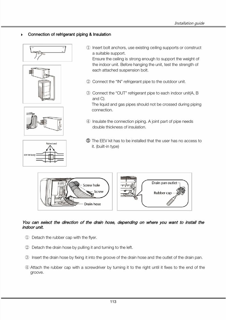
7/24/2019 2011 DVM_Installation Guide
http://slidepdf.com/reader/full/2011-dvminstallation-guide 113/137
Installation guide
113
Connection of refrigerant piping Insulation
① Insert bolt anchors, use existing ceiling supports or construct
a suitable support.
Ensure the ceiling is strong enough to support the weight of
the indoor unit. Before hanging the unit, test the strength of
each attached suspension bolt.
② Connect the “IN” refrigerant pipe to the outdoor unit.
③ Connect the “OUT” refrigerant pipe to each indoor unit(A, B
and C).
The liquid and gas pipes should not be crossed during piping
connection.
④ Insulate the connection piping. A joint part of pipe needs
double thickness of insulation.
The EEV kit has to be installed that the user has no access to
it. (built-in type)
You can select the direction of the drain hose depending on where you wa nt to install the
indoor unit.
① Detach the rubber cap with the flyer.
② Detach the drain hose by pulling it and turning to the left.
③ Insert the drain hose by fixing it into the groove of the drain hose and the outlet of the drain pan.
④ Attach the rubber cap with a screwdriver by turning it to the right until it fixes to the end of thegroove.

7/24/2019 2011 DVM_Installation Guide
http://slidepdf.com/reader/full/2011-dvminstallation-guide 114/137
5. Outdoor Units installation
114
1. Safety Information
1) Caution Signs(1) Make sure of a earthing.
① Do not connect the earth wire to the gas pipe, water pipe, lighting rod or telephone wire. If
earthing is incomplete, electric shock or fire may occur.
(2) Do not connect the heater to the outdoor unit and do not install altered duct as you please.
① The capacity may reduce, electric shock or fire may occur.
(3) Make sure that the condensed water dripping from the drain hose runs out properly and insulatethe drainpipe so that frost does not generate.
① Household goods may get wet if the drainpipe is not properly installed.
(4) Install the indoor unit away from lighting apparatus using the ballast.
① If you use the wireless remote control, it may not operate normally.
(5) Do not install the air conditioner in following places.
① The place where there is mineral oil or arsenic acid.
② Those parts may get damaged due to burned resin.
③ The efficiency of the heat exchanger may reduce or the air conditioner may be out of order.
④ The place where corrosive gas such as sulfurous acid gas generates from the vent pipe or airoutlet.
⑤ The copper pipe or connection pipe may corrode and refrigerant may leak.
⑥ The place where there is a machine that generates electromagnetic waves.
⑦ The air conditioner may not operate normally due to control system.
⑧ The place where there is a danger of existing combustible gas, thinner or gasoline is handled.
⑨ The place where carbon fiber or flammable dust is.
⑩ The place where like spa and shore.
(6) Install the power cable and communication cable of the indoor and outdoor unit at least 1.5maway from the electric appliances and install it at least 2m away from the cable from the lightningrod.
① Noise may heard depending on the electric wave though the cables.

7/24/2019 2011 DVM_Installation Guide
http://slidepdf.com/reader/full/2011-dvminstallation-guide 115/137
Installation guide
115
(7) Install the outdoor unit within the angle of 25~55˚ depending on the building height as belowtable.
Building height
Protective angle
Remarks
Below 20m 55°
Below 40m 35°
Below 60m 25°
2. Preparing the Installation
1) Moving the Outdoor Unit
(1) When moving with a crane or straps.
① Fasten the wire rope as seen in the picture.
A. To protect damage or scratches, insert a piece of cloth between the outdoor unit and thewire rope.
(2) When moving with a fork lift.
① Insert the fork into the bottom of the outdoor unit carefully.② Be careful that the fork does not damage the outdoor unit.

7/24/2019 2011 DVM_Installation Guide
http://slidepdf.com/reader/full/2011-dvminstallation-guide 116/137
5. Outdoor Units installation
116
2) Detaching Fasteners
① Open the bottom cabinet with screw driver.
② Detach nut washer, washer and stopper nut from compressors with a tool.
③ Refasten the nut washer only.

7/24/2019 2011 DVM_Installation Guide
http://slidepdf.com/reader/full/2011-dvminstallation-guide 117/137
Installation guide
117
3. Selecting Proper Location for Installation
1) Caution
(1) Install the indoor unit away from any interfering sources such as radio, computer, stereo equipment
and also select the place where the electrical wiring work can be possible.
① Especially keep the unit at least 3m away from the electrical equipment in an area
electromagnetic waves generated and install the protection tube to protect the main power
cable and communication cable.
② Make sure that there is no equipment electromagnetic waves generate. If not, malfunction of
the control system may occur due to the effect of the electromagnetic wave. (For example: The
remote control sensor of the indoor unit may not be received well of electronic lighting style
fluorescent lamps, such as fluorescent lamps are in the same space when using a remotecontrol.)
(2) Make sure to install the outdoor unit in a safe place where snowfall will not be obstructed. The
frame should be installed in a place where the air inlet and heat exchanger of the unit are not
buried in the snow.
(3) Ventilation system will be better installed for the case of the refrigerant leakage in a closed room
even if R410A is nonpoisonous and noninflammable refrigerant.
(4) Install the railing around the outdoor unit to prevent falling when the unit is installed at high place of
roof on the building.
(5) Avoid installing the units in places such as an exhaust pipe and ventilating opening exposed to
corrosive gas, oxides of sulfur, ammonia gas or sulfur gas herbicides.(Corroding copper pipes or soldered parts may result in refrigerant leakage.)
2) Caution for MCU
(1) Make sure to install MCU when using HR products.
(2) When you select the location to install MCU, the location is far away from indoor rooms becausethe refrigerant running of MCU may create noise.
3) Caution for Seashore
(1) Install the outdoor unit like a place where the product can beprotected from a direct sea breeze.
(2) If you cannot help installing the outdoor unit by the seashore,
construct a protection wall around the outdoor unit to protect the
sea breeze.
( Protection wall size : 150% larger than outdoor unit size)
(Min. 700mm distance for air circulation from the protection wall)

7/24/2019 2011 DVM_Installation Guide
http://slidepdf.com/reader/full/2011-dvminstallation-guide 118/137
5. Outdoor Units installation
118
4. Space Requirements
1) Single Installation
2) Group Installation

7/24/2019 2011 DVM_Installation Guide
http://slidepdf.com/reader/full/2011-dvminstallation-guide 119/137
Installation guide
119
3) Recommended Case
(1) At least 200mm(8inch) of space between the outdoor units is needed for service area and heat
radiation.
(2) When the product is installed in the site near the sea, wind-proof cover must be installedadditionally, considering effects from typhoon and seasonal wind. Anti-corrosion type must beselected. (Special coating must be applied.)
(3) All the ventilation systems, which are installed outdoors, should be apart from the outdoor unit. Incase they cannot be apart, the direction of the ventilation should be opposite direction to theoutdoor unit.

7/24/2019 2011 DVM_Installation Guide
http://slidepdf.com/reader/full/2011-dvminstallation-guide 120/137
5. Outdoor Units installation
120
5. Base Mount Construction
1) Base Mount Construction
2) Outdoor Unit Installation
3) Outdoor Unit Base Mount and Anchor Bolt Position
Heat Pump
RVXVHT080/100/120 RVXVHT140/160
Heat Recovery
RVXVRT080/100/120 RVXVRT140/160
A
880 1200
B
738 1058

7/24/2019 2011 DVM_Installation Guide
http://slidepdf.com/reader/full/2011-dvminstallation-guide 121/137
Installation guide
121
4) Anchor Specifications
Size
Diameter of
drill bit(a)
Anchor
length(b)
Sleeve
length(c)
Insert depth
Fastening
torque
Φ10 14mm 75mm 40mm 50mm 30N·m
5) Caution
(1) When tightening the anchor bolt.
Tighten the rubber washer to prevent the outdoor unit bolt connection part from corroding.
(2) When connecting the pipes.
① Check the strength of the roof to install the outdoor unit and make sure to have a waterprooffloor of the roof.
② Make sure that a proper drainage system has been put in place around the outdoor unit.
③ To protect the internal components of the outdoor unit, secure the pipe work entrance to theunit.

7/24/2019 2011 DVM_Installation Guide
http://slidepdf.com/reader/full/2011-dvminstallation-guide 122/137
5. Outdoor Units installation
122
6) Recommended Case
(1) Construct a concrete foundation in accordance with the standards for the site where outdoor unit
is being installed.
① H-beam: over 200mm
② Area of the concrete foundation must be 1.5 times larger than the outdoor unit.
③ Concrete foundation shouldn’t be slanted and condensed water needs to flow away withoutany stagnation
(2) After placing the outdoor unit on the basic foundation, fix the outdoor unit with the anchorbolt(M12).
(3) Install the anti-vibration pad between the outdoor unit, H-beam and the concrete foundation.
(t = over 20mm)

7/24/2019 2011 DVM_Installation Guide
http://slidepdf.com/reader/full/2011-dvminstallation-guide 123/137
Installation guide
123
6. Drain Pipe Installation
1) Installing the Drainpipe
(1) Insert the provided drain plug at the 2 sides of the bottom of the unit and then connect thedrainpipe.
(2) Install the drainpipe at the rear side of the unit to get a sufficient space for repairs and service.
2) When Installing Single Outdoor Unit
3) When Installing Multiple Outdoor Unit
4) Caution
(1) Do not install a trap on the pipe. And, install the drainpipe horizontally with a slope of 1/50 or more.
(2) Insulate the drainpipe and drain plug with insulation over 10t.
(3) Install heating device to the drainpipe to prevent it from being frozen. Install the safety equipmentfor a heating appliance.

7/24/2019 2011 DVM_Installation Guide
http://slidepdf.com/reader/full/2011-dvminstallation-guide 124/137
5. Outdoor Units installation
124
7. Exhaust Duct Installation
1) Installing Duct for Horizontal Exhaust Duct
2) Recommended Case
[Before] [After]

7/24/2019 2011 DVM_Installation Guide
http://slidepdf.com/reader/full/2011-dvminstallation-guide 125/137
Installation guide
125
8. Installing the Outdoor Unit Harsh Environments
1) General Instructions
(1) In abnormally harsh environments such as cold and/or windy areas, sufficient countermeasures toguard against excessive wind and snow should be taken to ensure the unit’s correct operation.
(2) Snow-proof duct (field supply) should be fitted to the unit and direct exposure to the wind shouldbe avoided as much as possible.
(3) When the unit is expected to operate in heating mode in condition under -10℃, in snowy area, in
environments subject to strong winds or rain, install air inlet and outlet ducting as shown below.
Caution
a. The frame/foundation should be higher than expected snowfall.
b. When installing on a roof subject to strong wind, countermeasures must be taken toprevent the unit from being overturned.
c. Any lack of strength may cause unit to fall down, resulting in a personal injury.
Installation example.
- When the product is installed in the site near the sea, wind-proof cover must be installedadditionally, considering effects from typhoon and seasonal wind. Anti-corrosion type must beselected. (Special coating must be applied)

7/24/2019 2011 DVM_Installation Guide
http://slidepdf.com/reader/full/2011-dvminstallation-guide 126/137
5. Outdoor Units installation
126
2) Dimensional Drawing of Snow-proof Duct
(1) Small Chassis
(2) Large Chassis

7/24/2019 2011 DVM_Installation Guide
http://slidepdf.com/reader/full/2011-dvminstallation-guide 127/137
Installation guide
127
9. Louver Installation
1) Requirements of Louver installation
(1) Opening rate: 80% and more.
(2) Louver angle(Blade Slope): 20° and less.
(3) Louver shape: Don’t use drainable blade type.
Good
Bad
(4) Air velocity of inlet side: 2.0m/s and less.

7/24/2019 2011 DVM_Installation Guide
http://slidepdf.com/reader/full/2011-dvminstallation-guide 128/137
5. Outdoor Units installation
128
10. Electrical Wiring Work
1) General Instructions
(1) All wiring, components and materials to be procured on the site must comply with the applicable
local and national codes.
(2) Be sure to comply with the specifications of the circuit breaker and power cable in installation
manual.
2) Power Supply and Communication Cable Configuration

7/24/2019 2011 DVM_Installation Guide
http://slidepdf.com/reader/full/2011-dvminstallation-guide 129/137
Installation guide
129
3) Circuit Breaker Installation
(1) 3 phase 4 wires
① Case 1
② Case 2
(2) 3 phase 3 wires and 1 phase 2 wires
① Case 1
② Case 2

7/24/2019 2011 DVM_Installation Guide
http://slidepdf.com/reader/full/2011-dvminstallation-guide 130/137
5. Outdoor Units installation
130
4) Wiring Diagram
(1) CO/HP Model
(2) HR Model
※ If the communication cable between indoor and outdoor units and the communication cable
among outdoor units are crossed, communication isn’t available.

7/24/2019 2011 DVM_Installation Guide
http://slidepdf.com/reader/full/2011-dvminstallation-guide 131/137
Installation guide
131
5) Connecting the power terminal
(1) Use solderless ring terminal to connect cable and terminal block.
Good Bad
(2) Install the cable according to a blueprint.
(3) Install the wire box, with uncovered insulation tube, to the product.
(4) During the installation in the site, make sure the wires and pipes do not contact each other
because the vibration of compressor and high temperature pipe can make damage to wiring.

7/24/2019 2011 DVM_Installation Guide
http://slidepdf.com/reader/full/2011-dvminstallation-guide 132/137
5. Outdoor Units installation
132
6) Power Cable Arrangement
(1) Make sure all wiring should not contact with piping line during the field wiring work. If not, the
vibration of compressor and high temperature pipe can make damage to wiring
Good
Bad
7) Circuit Breaker Installation
(1) Install a circuit breaker. For safety and maintenance, we strongly recommend that MCCB and ELB
and(or ELCB alone) have to be installed every outdoor unit.
(2) Every system must be installed individual MCCB and ELB and the specification must meet the
requirements.
Good
Bad

7/24/2019 2011 DVM_Installation Guide
http://slidepdf.com/reader/full/2011-dvminstallation-guide 133/137
Installation guide
133
11. Pump-Down Operation
1) General Instructions(1) Pump-down operation is to gather the refrigerant into outdoor unit.
(2) If system is under extremely low pressure, compressor will be damaged. When low pressure go
down 2kgf/ ㎠ or below, close the service valve quickly.
2) Procedure of Pump down operation
Close Liquid SVC Valve ose as a ve o u n
Single Installation Group Installation
Press “K2” button 3 timesfor pump down operation
Push “K4” button 4 times for
checking low pressure *1)
*1) “40 32”
- “4” means low pressure view mode
- “0 32” means low pressure is 3.2kgf/㎠g
If low pressure ≤
2kgf/㎠
Comp. On
Close Gas SVC Valve
(of Main Unit)
Press “K2” button 2 times
or “K3” button 1 time
for the end of pump down operation
Press “K2” button 3 timesfor pump down operation
Wait 20~30minutes
Comp. On
Close Liquid SVC Valve of Sub Unit
Close Liquid SVC Valve of Main Unit

7/24/2019 2011 DVM_Installation Guide
http://slidepdf.com/reader/full/2011-dvminstallation-guide 134/137
5. Outdoor Units installation
134
12. Pump-Out Procedure
1) General Instructions
(1) Pump-out is the name of operation which pumps out the refrigerant from outdoor unit.
(2) Pump out operation can be put into operation with more than 2 outdoor units installed.
(3) If system is under extremely low pressure, compressor will be damaged. When low pressure go
down 2kgf/ ㎠ or below, close the service valve quickly.
2) Procedure of Pump down operation
Close Liquid SVC Valve ofoutdoor unit to carry out pump
out operation
roup ns a a on
Press “K1” button for assigning
the outdoor unit *1)
Push “K4” button 4 times for
checking low pressure
*1) Press 1 time Main Outdoor unit
2 times Sub 1 Outdoor unit
3 times Sub 2 Outdoor unit
4 times Sub 3 Outdoor unit
If low pressure ≤
2kgf/㎠
Comp. On
Close Gas SVC Valve ofoperating outdoor unit
Press “K2” button 2 times
or “K3” button 1 time
for the end of pump out operation

7/24/2019 2011 DVM_Installation Guide
http://slidepdf.com/reader/full/2011-dvminstallation-guide 135/137
Installation guide
135
13. Setting the Option Switches & Function Keys
1) General Instruction
(1) Refer to the installation manual for details.
(2) Functions are activated by PCB of “Main unit” only.
2) Check List
Contents
Check
Outdoor Unit
The number of connected indoor unit
Outdoor unit address
The number of connected MCU (HR model only)
EEV Kit Indoor unit address
MCU
Indoor unit’s activating switch setting
Indoor unit address
MCU address
Indoor Unit Indoor unit address (Main, RMC)

7/24/2019 2011 DVM_Installation Guide
http://slidepdf.com/reader/full/2011-dvminstallation-guide 136/137
5. Outdoor Units installation
136
14. Completing the Installation and Commissioning
1) Check List
Contents
Check
Are the outdoor and indoor unit fixed securely?
Is the place well-ventilated and ensures space for service?
Is total number of connecting indoor units in the allowable range?
Are the length and the difference between the refrigerant pipes within theallowable range?
Is the ref. and drain properly insulated?
Have you completed the gas leak and drain test?
Is the wiring route correct?
Have you performed the earth work to the outdoor unit?
Are wiring specifications according to the installation manual and nationalstandards?
Is the length of the wire is in the limited range?
Have you completed the drain test?
Are the addresses of the indoor and outdoor units properly set?
Is the switch setting of the indoor units for centralized control properly made?
Have you written the installation check card?

7/24/2019 2011 DVM_Installation Guide
http://slidepdf.com/reader/full/2011-dvminstallation-guide 137/137
Installation guide