2011 buchanan lecture-cold war legacy design costruction and performance of a land_based radioactive...
TRANSCRIPT

8/11/2019 2011 Buchanan Lecture-Cold War Legacy Design Costruction and Performance of a Land_Based Radioactive Waste Disposal Facility-Bonaparte
http://slidepdf.com/reader/full/2011-buchanan-lecture-cold-war-legacy-design-costruction-and-performance-of 1/56
TThhee NNiinneetteeeenntthh SSppeenncceerr BBuucchhaannaann L Leeccttuurree
FFrriiddaayy NNoo v v eemm b beerr 1111tthh,,
22001111 CCoolllleeggee SSttaattiioonn HHiillttoonn CCoolllleeggee SSttaattiioonn,, TTee x xaass,, UUSS A A
hhttttpp:: / / / / cceepprrooffss..ttaammuu..eedduu / / b brriiaauudd / / b buucchhaannaann..hhttmm
CCoolldd W W aarr L Leeggaaccyy –– DDeessiiggnn,, CCoonnssttrruuccttiioonn,, aanndd PPeerrffoorrmmaannccee ooff aa
L Laanndd--BBaasseedd RRaaddiiooaaccttii v v ee W W aassttee DDiissppoossaall FFaacciilliittyy
RReeiinnffoorrcceedd SSooiill TTeecchhnnoollooggyy:: FFrroomm EE x xppeerriimmeennttaall ttoo tthhee
FFaammiilliiaarr
T T h h e e 2 2 0 0 1 1 0 0 K K a a r r l l T T e e r r z z a a g g h h i i L L e e c c t t u u r r e e BByy PPrrooff.. RRoo b beerrtt DD.. HHoollttzz

8/11/2019 2011 Buchanan Lecture-Cold War Legacy Design Costruction and Performance of a Land_Based Radioactive Waste Disposal Facility-Bonaparte
http://slidepdf.com/reader/full/2011-buchanan-lecture-cold-war-legacy-design-costruction-and-performance-of 2/56
Table of Contents
Spencer J. Buchanan 2
Donors 4
Spencer J. Buchanan Lecture Series 7 Agenda 8
Prof. Robert D. Holtz 9
Prof. Robert D. Holtz“Reinforced Soil Technology: From Experimental to the Familiar”
10
Dr. Rudolph Bonaparte 27
Dr. Rudolph Bonaparte“Cold War Legacy – Design, Construction, and Performance of a Land-
Based Radioactive Waste Disposal Facility”
28
Pledge Information
1
8/11/2019 2011 Buchanan Lecture-Cold War Legacy Design Costruction and Performance of a Land_Based Radioactive Waste Disposal Facility-Bonaparte
http://slidepdf.com/reader/full/2011-buchanan-lecture-cold-war-legacy-design-costruction-and-performance-of 3/56
SPENCER J. BUCHANAN
Spencer J. Buchanan, Sr. was born in 1904 in Yoakum, Texas. He graduated fromTexas A&M University with a degree in Civil Engineering in 1926, and earned graduateand professional degrees from the Massachusetts Institute of Technology and Texas A&MUniversity.
He held the rank of Brigadier General in the U.S. Army Reserve, (Ret.), andorganized the 420th Engineer Brigade in Bryan-College Station, which was the only suchunit in the Southwest when it was created. During World War II, he served the U.S. ArmyCorps of Engineers as an airfield engineer in both the U.S. and throughout the islands of thePacific Combat Theater. Later, he served as a pavement consultant to the U.S. Air Forceand during the Korean War he served in this capacity at numerous forward airfields in thecombat zone. He held numerous military decorations including the Silver Star. He wasfounder and Chief of the Soil Mechanics Division of the U.S. Army Waterways ExperimentStation in 1932, and also served as Chief of the Soil Mechanics Branch of the MississippiRiver Commission, both being Vicksburg, Mississippi.
2

8/11/2019 2011 Buchanan Lecture-Cold War Legacy Design Costruction and Performance of a Land_Based Radioactive Waste Disposal Facility-Bonaparte
http://slidepdf.com/reader/full/2011-buchanan-lecture-cold-war-legacy-design-costruction-and-performance-of 4/56
He was the founder and president of Spencer J. Buchanan & Associates, Inc.,
Consulting Engineers, and Soil Mechanics Incorporated in Bryan, Texas. These firms wereinvolved in numerous major international projects, including twenty-five RAF-USAFairfields in England. They also conducted Air Force funded evaluation of all U.S. AirTraining Command airfields in this country. His firm also did foundation investigations fordowntown expressway systems in Milwaukee, Wisconsin, St. Paul, Minnesota; LakeCharles, Louisiana; Dayton, Ohio, and on Interstate Highways across Louisiana. Mr.Buchanan did consulting work for the Exxon Corporation, Dow Chemical Company,
Conoco, Monsanto, and others.
Professor Buchanan was active in the Bryan Rotary Club, Sigma Alpha EpsilonFraternity, Tau Beta Pi, Phi Kappa Phi, Chi Epsilon, served as faculty advisor to the StudentChapter of the American Society of Civil Engineers, and was a Fellow of the Society of American Military Engineers. In 1979 he received the award for Outstanding Service fromthe American Society of Civil Engineers.
Professor Buchanan was a participant in every International Conference on Soil Mechanics and Foundation Engineering since 1936. He served as a general chairman ofthe International Research and Engineering Conferences on Expansive Clay Soils at Texas A&M University, which were held in 1965 and 1969.
Spencer J. Buchanan, Sr., was considered a world leader in geotechnical
engineering, a Distinguished Texas A&M Professor, and one of the founders of the BryanBoy’s Club. He died on February 4, 1982, at the age of 78, in a Houston hospital after anillness, which lasted several months.
3

8/11/2019 2011 Buchanan Lecture-Cold War Legacy Design Costruction and Performance of a Land_Based Radioactive Waste Disposal Facility-Bonaparte
http://slidepdf.com/reader/full/2011-buchanan-lecture-cold-war-legacy-design-costruction-and-performance-of 5/56
The Spencer J. Buchanan ’26 Chair in Civil Engineering
The College of Engineering and the Department of Civil Engineering gratefully recognize thegenerosity of the following individuals, corporations, foundations, and organizations for their part in
helping to establish the Spencer J. Buchanan ’26 Professorship in Civil Engineering. Created in 1992 tohonor a world leader in soil mechanics and foundation engineering, as well as a distinguished Texas A&M University professor, the Buchanan Professorship supports a wide range of enriched educationalactivities in civil and geotechnical engineering. In 2002, this professorship became the Spencer J.Buchanan ’26 Chair in Civil Engineering.
Donors
Founding Donor
C.Darrow Hooper ‘53
Benefactors ( 5,000+)
Flatt Partners, LmtdMr. Spencer J. Buchanan, Jr. '53
ETTL Engineers and Consultants, Inc.East Texas Testing Laboratory, Inc.
Patrons ( 1,000- 4,999)
Dionel E. Aviles ‘53
Aviles Engineering Corporation
Willy F. Bohlmann, Jr. ‘50Mark W. Buchanan
The Dow Chemical Company Foundation
George D. Cozart ’74Wayne A. Dunlap ‘52
Douglas E. Flatt ‘53
Perry G. Hector ‘54
James D. Murff ‘70
Donald R. Ray ‘68
Spencer J. Buchanan Associates, Inc.L. Anthony Wolfskill ’53
Jose M. Roesset
Kenneth H. StokoeRudolph Bonaparte
Br. Gen. John C.B. Elliott
Robert S. Patton ‘61
4

8/11/2019 2011 Buchanan Lecture-Cold War Legacy Design Costruction and Performance of a Land_Based Radioactive Waste Disposal Facility-Bonaparte
http://slidepdf.com/reader/full/2011-buchanan-lecture-cold-war-legacy-design-costruction-and-performance-of 6/56
Members ( 100- 499)
Adams Consulting Engineers, Inc.
Demetrios A. Armenakis ‘58
Eli F. Baker ‘47B.E. Beecroft ‘51
Fred J. Benson ‘36
G.R. Birdwell Corporation, Inc.Craig C. Brown ‘75
Donald N. Brown ‘43
Ronald C. Catchings ‘65Ralph W. Clement ‘57
Coastal Bend Engineering Association John W.Cooper III ‘46
George W. Cox ‘35Mr. and Mrs. Harry M. Coyle
Murray A. Crutcher ‘74
Enterprise EngineersDodd Geotechnical Engineering
Donald D. Dunlap ‘58
Edmond L. Faust ‘47David T. Finley ‘82
Charles B. Foster, Jr. ‘38
Benjamin D. Franklin ‘57Thomas E. Frazier ‘77
William F. Gibson ‘59Cosmo F. Guido ‘44
Joe G. Hanover ‘40
John L. Hermon ‘63William and Mary HollandW. Ronald Hudson ‘54
W.R. Hudson Engineering
Homer A. Hunter ‘25Iyllis Lee Hutchin
Mr. & Mrs. Walter J. Hutchin ‘47
Mary Kay Jackson ‘83
Hubert O. Johnson, Jr. ‘41
Lt. Col. William T. Johnson, Jr. ‘50
Homer C. Keeter, Jr. ‘47Richard W. Kistner ‘65
Charles M. Kitchell, Jr. ‘51
Mr. & Mrs. Donald KlinzingAndrew & Bobbie Layman
Mr. & Mrs. W.A. Leaterhman, Jr.
F. Lane Lynch ‘60Charles McGinnis ‘49
Jes D. McIver ‘51Charles B. McKerall, Jr. ‘50
Morrison-Knudsen Co.,Inc.Jack R. Nickel ‘68
Roy E. Olson
Nicholas Paraska ‘47Daniel E. Pickett ‘63
Pickett-Jacobs Consultants, Inc.
Richard C. Pierce ‘51Robert J. Province ‘60
David B. Richardson ‘76
David E. Roberts ‘61Walter E. Ruff ‘46
Weldon Jerrell Sartor ‘58Charles S. Skillman, Jr. ‘52
Soil Drilling Services
Louis L. Stuart, Jr. ‘52Ronald G. Tolson, Jr. ‘60Hershel G. Truelove ‘52
Mr. & Mrs. Thurman Wathen
Ronald D. Wells ‘70Andrew L. Williams, Jr. ‘50
Dr. & Mrs. James T.P. Yao
Associates ( 25- 99)
5

8/11/2019 2011 Buchanan Lecture-Cold War Legacy Design Costruction and Performance of a Land_Based Radioactive Waste Disposal Facility-Bonaparte
http://slidepdf.com/reader/full/2011-buchanan-lecture-cold-war-legacy-design-costruction-and-performance-of 7/56
Lawrence & Margaret CecilHoward T. Chang ‘42
Mrs. Lucille Hearon Chipley
Caroline R. Crompton
Mr. & Mrs. Joseph R. Compton
Robert J. Creel ‘53Robert E. Crosser ‘49
O. Dexter DabbsGuy & Mary Bell Davis
Robert & Stephanie Donaho
Mr. Charles A. DrabekStanley A. Duitscher ‘55
Mr. & Mrs. Nelson D. Durst
George H. Ewing ‘46
Edmond & Virginia FaustFirst City National Bank of Bryan
Neil E. Fisher ‘75
Peter C. Forster ‘63Mr. & Mrs. Albert R. Frankson
Maj. Gen Guy & Margaret Goddard
John E. Goin ‘68Mr. & Mrs. Dick B. Granger
Howard J. Guba ‘63
James & Doris HanniganScott W. Holman III ‘80
Lee R. Howard ‘52Mrs. Jack Howell
Col. Robert & Carolyn Hughes
William V. Jacobs ‘73Ronald S. Jary ‘65Mr. Shoudong Jiang ‘01
Richard & Earlene G. Jones
William M. Wolf, Jr. ‘65John S. Yankey III ‘66
H.T. Youens, Sr.
William K. Zickler ‘83
Ronald P. Zunker ‘62
Mr. & Mrs. Charles A LawlerMrs. John M. Lawrence, Jr.
Mr. & Mrs. Yan Feng Li
Jack & Lucille Newby
Lockwood, Andrews, & Newman, Inc.
Robert & Marilyn LyttonLinwood E. Lufkin ‘63
W.T. McDonaldJames & Maria McPhail
Mr. & Mrs. Clifford A. Miller
Minann, Inc.Mr. & Mrs. J. Louis Odle
Leo Odom
Mr. & Mrs. Bookman Peters
Charles W. Pressley, Jr. ‘47Mr. & Mrs. D.T. Rainey
Maj. Gen. & Mrs. Andy Rollins and J. Jack Rollins
Mr. & Mrs. J.D. Rollins, Jr.Mr. & Mrs. John M. Rollins
Allen D. Rooke, Jr. ‘46
Paul D. Rushing ‘60S.K. Engineering
Schrickel, Rollins & Associates, Inc.
William & Mildred H. ShullMilbourn L. Smith
Southwestern LaboratoriesMr. & Mrs. Homer C. Spear
Robert F. Stiles ‘79
Mr. & Mrs. Robert L. Thiele, Jr.W. J. & Mary Lea TurnbullMr. & Mrs. John R. Tushek
Edward Varlea ‘88
Constance H. WakefieldTroy & Marion Wakefield
Mr. & Mrs. Allister M. Waldrop
Kenneth C. Walker ‘78
Robert R. Werner ‘57
Every effort was made to ensure the accuracy of this list. If you feel there is an error, please contact the
E D Off 979 845 5113 A f
6

8/11/2019 2011 Buchanan Lecture-Cold War Legacy Design Costruction and Performance of a Land_Based Radioactive Waste Disposal Facility-Bonaparte
http://slidepdf.com/reader/full/2011-buchanan-lecture-cold-war-legacy-design-costruction-and-performance-of 8/56
Spencer J Buchanan Lecture Series
1993 Ralph B. Peck “The Coming of Age of Soil Mechanics: 1920 - 1970”
1994 G. Geoffrey Meyerhof “Evolution of Safety Factors and Geotechnical Limit State Design”
1995 James K. Mitchell “The Role of Soil Mechanics in Environmental Geotechnics”
1996 Delwyn G. Fredlund “The Emergence of Unsaturated Soil Mechanics”
1997 T. William Lambe “The Selection of Soil Strength for a Stability Analysis”
1998 John B. Burland “The Enigma of the Leaning Tower of Pisa”
1999 J. Michael Duncan “Factors of Safety and Reliability in Geotechnical Engineering”
2000 Harry G. Poulos “Foundation Settlement Analysis – Practice Versus Research”
2001 Robert D. Holtz “Geosynthetics for Soil Reinforcement”
2002 Arnold Aronowitz “World Trade Center: Construction, Destruction, and Reconstruction”
2003 Eduardo Alonso “Exploring the Limits of Unsaturated Soil Mechanics: the Behavior ofCoarse Granular Soils and Rockfill”
2004 Raymond J. Krizek “Slurries in Geotechnical Engineering”
2005 Tom D. O’Rourke “Soil-Structure Interaction Under Extreme Loading Conditions”
2006 Cylde N. Baker “In Situ Testing, Soil-Structure Interaction, and Cost Effective FoundationDesign”
2007 Ricardo Dobry “Pile response to Liquefaction and Lateral Spreading: Field Observations
and Current Research”
2008 Kenneth Stokoe "The Increasing Role of Seismic Measurements in GeotechnicalEngineering"
2009 Jose M. Roesset “Some Applications of Soil Dynamics”
2010 Kenji Ishihara “Forensic Diagnosis for Site-Specific Ground Conditions in Deep
Excavations of Subway Constructions”
2011 Rudolph Bonaparte “Cold War Legacy – Design, Construction, and Performance of a Land-
Based Radioactive Waste Disposal Facility”
7

8/11/2019 2011 Buchanan Lecture-Cold War Legacy Design Costruction and Performance of a Land_Based Radioactive Waste Disposal Facility-Bonaparte
http://slidepdf.com/reader/full/2011-buchanan-lecture-cold-war-legacy-design-costruction-and-performance-of 9/56
AGENDA
The Nineteenth Spencer J. Buchanan LectureFriday, November 11th, 2011
College Station Hilton
2:00 p.m. Introduction by Jean-Louis Briaud
2:15 p.m. Introduction of Robert D. Holtz by Stacey Tucker
2:20 p.m. “Reinforced Soil Technology: From Experimental to the Familiar”The 2010 Terzaghi Lecture by Robert D. Holtz
3:20 p.m. Introduction of Rudolph Bonaparte by Jean-Louis Briaud
3:25 p.m. “Cold War Legacy – Design, Construction, and Performance of a Land-Based Radioactive Waste Disposal Facility”The 2010 Buchanan Lecture by Rudolph Bonaparte
4:25 p.m. Discussion
4:40 p.m. Closure with Philip Buchanan
5:00 p.m. Photos followed by a reception at the home of Jean-Louis andJanet Briaud.
8

8/11/2019 2011 Buchanan Lecture-Cold War Legacy Design Costruction and Performance of a Land_Based Radioactive Waste Disposal Facility-Bonaparte
http://slidepdf.com/reader/full/2011-buchanan-lecture-cold-war-legacy-design-costruction-and-performance-of 10/56
Robert D. Holtz, PhD, PE, D.GE
Robert D. Holtz, PhD, PE, D.GE, is Professor Emeritus of Civil Engineering at the University of Washington inSeattle. He has degrees in civil engineering from Minnesota and Northwestern, and he participated in theSpecial Program in Soil Mechanics at Harvard under Professor A. Casagrande. Before coming to the UW in1988, he was on the faculty at Purdue and Cal State-Sacramento. In addition to experience with theCalifornia Dept. of Water Resources, Swedish Geotechnical Institute, and NRC-Canada, he has worked as aconsulting engineer in Chicago, Paris, France, and Milano, Italy. His research and publications are mostly ongeosynthetics, foundations, soil improvement, soil properties, and instrumentation, and his research has beensponsored by NSF, FHWA, US Air Force, Indiana Dept of Highways, Washington State Dept ofTransportation, Washington Technology Center, ADSC, US Dept. of Energy, and several private companies.Professor Holtz is author, co-author, or editor of 23 books and book chapters, including Introduction toGeotechnical Engineering , 2nd Edition (with W. D. Kovacs and T.C. Sheahan, 2011). He is also author or co-author of more than 270 technical papers, discussions, reviews, and major reports.
Professor Holtz is a Fellow, Life, and Distinguished Member of ASCE, was President of the Geo-Institute of ASCE in 2000-01, and currently serves as International Secretary for the Geo-Institute. He is a MemberEmeritus of TRB Committee on Soil and Rock Properties, a Past President of North American GeosyntheticsSociety; and a member of several other professional and technical organizations. Bob is a registered engineerin California and Indiana, and he is a Diplomate of the Academy of Geo-Professionals.
Professor Holtz has taught numerous short courses and given many presentations at seminars andconferences, both in the U.S. and abroad. He was the Cross-Canada and the 38th Ardaman Lecturers in1999, the 9th Spencer J. Buchanan Lecturer (2001), and he held the J. S. Braun/Braun Intertec VisitingProfessorship at the University of Minnesota in 2002. He gave the 8th R. L. Schiffman ‘44 Lecture (2003),the 3rd G. A. Leonards Lecturer in 2005, the Stanley D. Wilson Memorial Lecturer in 2007, and in 2008, hepresented the H. R. Berg and the Lymon C. Reese Lectures. In 2009, he gave the Osterberg Geomechanics
Lecture, and in 2010, he was the 46th Karl Terzaghi Lecturer. He also has given the Terzaghi Lecture in
9

8/11/2019 2011 Buchanan Lecture-Cold War Legacy Design Costruction and Performance of a Land_Based Radioactive Waste Disposal Facility-Bonaparte
http://slidepdf.com/reader/full/2011-buchanan-lecture-cold-war-legacy-design-costruction-and-performance-of 11/56
GEOSYNTHETIC REINFORCED SOIL:FROM THE EXPERIMENTAL TO THE FAMILIAR
46th
Terzaghi Lecture
R. D. Holtz, PhD, PE, D.GE
Professor EmeritusUniversity of Washington
Seattle, Washington USA
ABSTRACT
The lecture begins with a historical review of reinforced soil technology, from the ancients, the
developments by H. Vidal and K. Lee on Terre Armée and Reinforced Earth, the early uses ofgeosynthetics for soil reinforcement in France (Bidim), Sweden (Wager and Broms), and the
USA (USFS, FHWA, J. R. Bell, T. A. Haliburton, B. R. Christopher and others). The
advantages and basic behavior of geosynthetic reinforced soil (GRS) are presented along with anoverview of current design procedures, and with reference to UW analytical research results.
Practical suggestions are given for dealing with creep, pullout, and backfill drainage.
Geosynthetic properties and then discussed, again with reference to UW research results.Although GRS is quite a mature development, a few technical and professional issues remain;
primarily, too many failures of these structures occur. Reasons for these failures and some
suggestions as to what the profession can do about them are presented. The lecture ends withseveral examples of successful applications of GRS and reinforced soil technology.
10
11

8/11/2019 2011 Buchanan Lecture-Cold War Legacy Design Costruction and Performance of a Land_Based Radioactive Waste Disposal Facility-Bonaparte
http://slidepdf.com/reader/full/2011-buchanan-lecture-cold-war-legacy-design-costruction-and-performance-of 12/56
GEOSYNTHETIC REINFORCED SOIL:FROM THE EXPERIMENTAL TO
THE FAMILIAR
46th Terzaghi Lecture
GEOSYNTHETIC REINFORCED SOIL:GEOSYNTHETIC REINFORCED SOIL:FROM THE EXPERIMENTAL TOFROM THE EXPERIMENTAL TO
THE FAMILIARTHE FAMILIAR
46th Terzaghi Lecture
R. D. Holtz, PhD, PE, D.GE
Professor Emeritus
University of Washington
Seattle, Washington USA
Kjellman paper drain installation,Halmsjön, Sweden, 1946 or 47?
Two previous Terzaghi Lectures
on Geosynthetics:
R. M. Koerner(1996)
Geomembranes:
properties and
behavior
J.-P. Giroud
(2008)
Geotextile and
granular filters
My two geosynthetics heroes…
Geosynthetics in Civil Engineering…
• From the experimental to accepted practice- Waste containment- Canal and pond liners- Drainage and erosion control- Construction- Transportation- Geotechnical
• “Geosynthetics - THE most important development in Civil
Engineering practice in the 20th Century.”(J.-P. Giroud, 2008 Terzaghi Lecture)
• The first new civil engineering material in more than 100 yr…
• Other examples…
My plan:
1. Introduction
2. Reinforced soil—a historical perspective
Some examples from nature andthe ancients:
Birds’ nests
11
12

8/11/2019 2011 Buchanan Lecture-Cold War Legacy Design Costruction and Performance of a Land_Based Radioactive Waste Disposal Facility-Bonaparte
http://slidepdf.com/reader/full/2011-buchanan-lecture-cold-war-legacy-design-costruction-and-performance-of 13/56
Ziggurat of Aquar-Quf, near Bagdad
~ 1500 BC
Now 45 m high (originally ~ 87 m) Dr. J.-P. Giroud at Aquar-Quf circa 1980
Great Wall of China
Western wall
How I got into soil reinforcing and geosynthetics:
Experience in Sweden, 1970-1975
Oleg Wager(1915-1992)
The inventor
Bengt Broms(1925 - )
Boss & collaborator
Alvängen, Sweden 1966
12
13

8/11/2019 2011 Buchanan Lecture-Cold War Legacy Design Costruction and Performance of a Land_Based Radioactive Waste Disposal Facility-Bonaparte
http://slidepdf.com/reader/full/2011-buchanan-lecture-cold-war-legacy-design-costruction-and-performance-of 14/56
SGI, 1972-1973
Holtz and Broms (1977)Conf on Fabrics… Paris
slope
(two sands)
SGI, 1974KTH, 1975
Holtz & Broms
(1978) Symp. on
Soil Reinf.,
Sydney
Henri Vidal
(1924 - 2008)
1966
Autoroute A53,
Nice-Menton,France (1967-8)
Terre Armée, near Paris, 1976
13
14

8/11/2019 2011 Buchanan Lecture-Cold War Legacy Design Costruction and Performance of a Land_Based Radioactive Waste Disposal Facility-Bonaparte
http://slidepdf.com/reader/full/2011-buchanan-lecture-cold-war-legacy-design-costruction-and-performance-of 15/56
LCPC, PARIS, 1976
KTH, 1975
First RECo wall
in the US, 1972:SR39, Angles
Natl Forest, S.
Calif.
Ken Lee’s work at UCLA
--Two NSF projects, 1970-1975
(1931-1978)
15

8/11/2019 2011 Buchanan Lecture-Cold War Legacy Design Costruction and Performance of a Land_Based Radioactive Waste Disposal Facility-Bonaparte
http://slidepdf.com/reader/full/2011-buchanan-lecture-cold-war-legacy-design-costruction-and-performance-of 16/56
… and walls with geosynthetics in 1971-77
1. Bidim wall in France, 1971-1972,reinforced with a polyester needlepunchednonwoven, 300 g/m2
Puig & Blivet (1973)Bull. liaison Labo.
Cent. P. et Ch.
2. USFS walls in Oregon andWashington, 1972-1975
USFS: J. Steward, J. Mohney, B. Vandre
OSU: Prof. J. R. Bell
Dick Bell
Siskiyou NF,
S. Oregon
Siskiyou NF, S. OregonOlympic NF, Washington
Siskiyou NF,
S. Oregon
Interim Report: FHWA/RD-80/021 (1980)Draft final report, 1982 (neverpublished by FHWA)
FHWA geosynthetics courses (~1978 - )
• Started by Al Haliburton, Okla St. U.
• Second contract BRC & RDH
Cover of Christopher and Holtz (1983) Geotextile Engineering Manual , FHWA,FHWA-TS-86/203, 1044 pp.
16

8/11/2019 2011 Buchanan Lecture-Cold War Legacy Design Costruction and Performance of a Land_Based Radioactive Waste Disposal Facility-Bonaparte
http://slidepdf.com/reader/full/2011-buchanan-lecture-cold-war-legacy-design-costruction-and-performance-of 17/56
My plan:
1. Introduction
2. Reinforced soil—a historical perspective
3. Advantages and basic behavior of GRS
4. Design
5. Properties
6. Things we need still need to know and do—technical and professional issues
7. Successful examples
8. Final remarks
Advantages…
1. Cost:
Other advantages besides cost…
2. Flexibility
• Settlement tolerance ( ¢¢ foundations)
• Easy to change alignment, grade
• Seismic stability
3. Simple, rapid construction
4. Attractive facing systems including“green” facings
Advantages (cont.)
5. Steeper slopes – – Cohesive >2:1Cohesive >2:1
– – Granular > angle of reposeGranular > angle of repose
6. Increased safety
For the same calculated FS, lower probability offailure (reliability greater) for a reinforced steeperslope than an unreinforced flatter slope
(Cheng & Christopher, 1991).
Why do we still design/construct unreinforced
soil slopes?
Basic behavior…
17

8/11/2019 2011 Buchanan Lecture-Cold War Legacy Design Costruction and Performance of a Land_Based Radioactive Waste Disposal Facility-Bonaparte
http://slidepdf.com/reader/full/2011-buchanan-lecture-cold-war-legacy-design-costruction-and-performance-of 18/56
Bob Barrett,Colorado
• Stress at face of wall/steep slope v small
• Therefore, face is only “local”… just
necessary to hold soil between layers
– not necessary to be structural, heavy,clunky (…unless the Sv is large.)
– Japanese experience with EQs?
Conclusions…
Fundamental studies on Texsol (1988-92)Kim Wargo-Levine and Shaun Stauffer, UW
My plan:
1. Introduction
2. Reinforced soil—a historical perspective
3. Advantages and behavior of GRS
4. Design
5. Properties
6. Things we need still need to know and do—technical and professional issues
7. Successful examples
8. Final remarks
DesignBackground (historical-traditional approaches)
• GRS walls: Combination of conventional EP theory (Rankine)and Terre Armée
Design…
• Koerner : Our design approaches dependon traditional geotech designs for slopes
18
8/11/2019 2011 Buchanan Lecture-Cold War Legacy Design Costruction and Performance of a Land_Based Radioactive Waste Disposal Facility-Bonaparte
http://slidepdf.com/reader/full/2011-buchanan-lecture-cold-war-legacy-design-costruction-and-performance-of 19/56
Prentice-HallBiTech Publishers,Richmond, BC
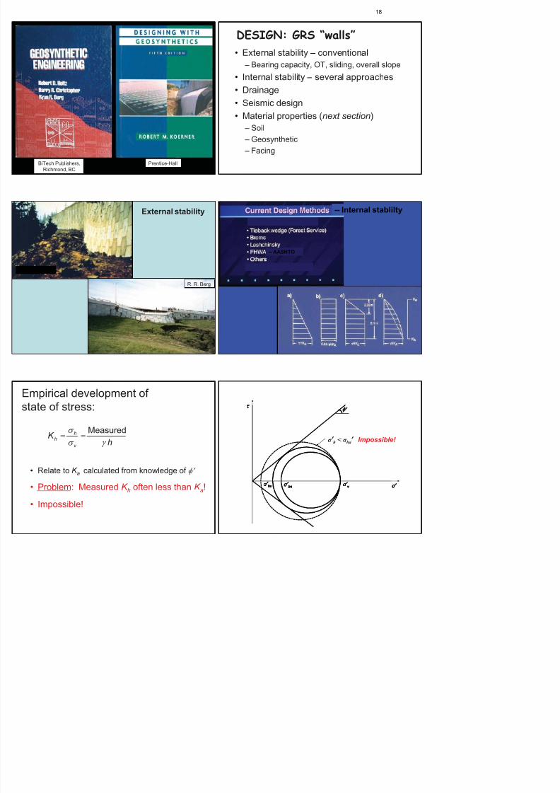
DESIGN: GRS “walls”
• External stability – conventional
– Bearing capacity, OT, sliding, overall slope
• Internal stability – several approaches• Drainage
• Seismic design
• Material properties (next section)
– Soil
– Geosynthetic
– Facing
Roseburg, Ore.
R. R. Berg
External stability -- Internal stablilty
-- AASHTO
Empirical development ofstate of stress:
Measured
19

8/11/2019 2011 Buchanan Lecture-Cold War Legacy Design Costruction and Performance of a Land_Based Radioactive Waste Disposal Facility-Bonaparte
http://slidepdf.com/reader/full/2011-buchanan-lecture-cold-war-legacy-design-costruction-and-performance-of 20/56
Field meas vs. theory? Why is K h << K a??
• Properties
– MFEs curved, so >> higher at low h or c
– TRIAX << PS
– At field densities, high
• Rankine theory violated by presence of reinforcement(Boyle, 1995, PhD thesis, UW)
• Apparent cohesion – “…a little c goes a long way!!” …but always there??
• Field meas ??
– Interpretation problems – Anomalies
– etc etc..
Design: GRS slopes…
Combination of classical slope stability analyses
+ “tieback” forces
Holtz & Kovacs (1981)
Consider
• how granular slopes actually fail
• how stability analyses are performed.
Start w/ a sand at itsangle of repose andthen increase theslope angle…
38
Sand
f 35
How much reinforcement is
needed for stability??
f 35
1
2 26
How much reinforcement is
needed for stability??
What happens if it fails?
Richard Jewell and the pullout paradox…
• Sliding wedge
– One plane
– Bilinear
• Circular arc
• Log spiral
GRS slopes:Design approaches and procedures
• Murray
• Schneider & Holtz
• Leshchinsky et al.
• Jewell
• Schmertmann et al.
• Verduin & Holtz• Others?
For stability analyses, several commercial andgovt-developed programs have subroutines for GRS
• PCSTABL4 • New Janbu
UW Research on GRS Walls:Analytical (FLAC)
1. Wei-Feng Lee (PhD) -- Analysis of GRS walls;d l ki t l i
20

8/11/2019 2011 Buchanan Lecture-Cold War Legacy Design Costruction and Performance of a Land_Based Radioactive Waste Disposal Facility-Bonaparte
http://slidepdf.com/reader/full/2011-buchanan-lecture-cold-war-legacy-design-costruction-and-performance-of 21/56
1. Wei Lee (PhD) -- Analysis of GRS walls; developworking stress analysis
• Model calibrated with field/lab data (Rainier Ave. wall)
• PS & modulus @ low c correct dilation angle
• Class A predictions of three RMC test walls; ~ good
agreement
Conclusion: Both external and internal performancecan be reproduced, IF :
• Correct material properties
• Boundary conditions correctly simulated
0
0.5
1
1.5
2
2.5
3
3.5
4
0 20 40 60 80 100 120Face Deflection (mm)
H e i g h t o f W a l l ( m )
Predicted-
50kPa
Measured-
50kPa
Predicted-
70kPa
Measured-
70kPa
Predicted-
115kPa
Measured-
115kPa
0.0
2.0
4.0
6.0
8.0
0 500 1000 1500 2000 2500 3000
Distance fromwall face ( mm)
S t r a i n ( % )
Layer2- Model RMC3Measured
0.0
2.0
4.0
6.0
8.0
0 500 1000 1500 2000 2500 3000
Distance fromwall face (mm)
S t r a i n ( % )
Layer3- Model RMC3
Measured
0.0
2.0
4.0
6.0
8.0
0 500 1000 1500 2000 2500 3000
Distance fromw all face (mm)
S t r a i n ( % )
Layer4- Model RMC3
Measured
Wall Deflection – Wall 1
Reinforcement Strain - Wall 3(50 kPa surcharge)
W.-F Lee (2000) PhD Thesis UW
2. Fazee Saidin (PhD) -- back analysis of aninstrumented full scale GRS wall with poor drainingbackfill on soft soil
• Instrumented 6 m LTRC wall
• Numerical simulation (FLAC) of GRS wall on soft foundation
• considered settlement, infiltration, compaction, etc., effects
FLAC (Version 5.00)
LEGEND
24-Aug-06 8:41 step 4120521Flow Time 1.0200E+07 -4.698E+00<x< 1.749E+01
-1.216E+01<y< 1.004E+01
Y-displacementcontours
-2.00E-01 -1.75E-01 -1.50E-01 -1.25E-01 -1.00E-01
-7.50E-02 -5.00E-02
-2.50E-02 0.00E+00
Contour interval= 2.50E-02Boundaryplot
0 5E 0
Cableplot -1.000
-0.600
-0.200
0.200
0.600
(*10^1)
-0.200 0.200 0.600 1.000 1.400(*10^1)
JOBTITLE :LOUISIANAWALLSECTION 1with consolidation
Universityof WashingtonSeattle
Gravelbase layer
-0.25
-0.20
-0.15
-0.10
-0.05
0.00
0 2 4 6 8 10 12 14
Distance from the facing (m)
S e t t l e m e n t ( m )
3.2 m(c alculated)
3.2 m(measured)
5.5 m(c alculated)
5.5 m(measured)
-0.25
-0.20
-0.15
-0.10
-0.05
0.00
0 2 4 6 8 10 12 14
Distance from the facing (m)
S e t t l e m e n t ( m )
3.2 m(c alculated)
3.2 m(measured)
5.5 m(c alculated)
5.5 m(measured)
F. Saidin (1997) PhD Thesis, UW
Some results--settlements
Design recommendations
• Traditional design methods OK for GRSwalls on soft foundations
R i f d b l if
21

8/11/2019 2011 Buchanan Lecture-Cold War Legacy Design Costruction and Performance of a Land_Based Radioactive Waste Disposal Facility-Bonaparte
http://slidepdf.com/reader/full/2011-buchanan-lecture-cold-war-legacy-design-costruction-and-performance-of 22/56
Sandri (2005) NAGS-GRI19
Other approaches to design:
• Composite material approach – UC Davis 1970s
– Lee et al. (2007) Proceedings of Geosyn. 2007
• K-Stiffness method – Empirical – many case histories
– Independent of reinforcing material
– More accurate estimate of reinforcement loads
– Step-by-step design procedures developed with alimit states design approach consistent withcurrent design codes (i.e., LRFD)
Allen, Bathurst, Holtz, Lee, and Walters(2003) CGJ and (2004) JGGE
So, what to do for design of GRS ?If you want to use traditional LE methods…
1. Use correct soil properties: h + PS (not so easy)
– not many PS devices available
– hard to conduct triax/PS tests at low confining pressures
– Use correct dilatancy (…important if want to do
advanced modeling, e.g., with FLAC…and you want the correct answer!)
2. For internal stability of steep GRS slopes, design as…..well, a
very steep slope.
As slope angle increases more or stronger reinforcing – Use SN or tieback programs…w/ adjustments for geometry and
properties of reinforcement (??)
– See Pockoski & Duncan (2000) “Comparison of Computer Programs for
Reinforced Slopes,” Center for Geotech Practice & Research, Va Tech
Traditional LE methods (cont.)3. Use thin layers of weaker reinforcing -- ¢¢, and
better face control4. Pullout? Not a problem—based on our research at
SGI, KTH (described earlier) – Geosynthetic will rupture before it pulls out
– If a problem, easily taken care of in design
5. …and don’t forget:
Drainage! Drainage! Drainage!
John Paulson
_________________
Also, try K-Stiffness Method*
*Let us know how it works
My plan:
1. Introduction
2. Reinforced soil—a historical perspective
Material PropertiesMaterial Properties
SoilsSoils
22

8/11/2019 2011 Buchanan Lecture-Cold War Legacy Design Costruction and Performance of a Land_Based Radioactive Waste Disposal Facility-Bonaparte
http://slidepdf.com/reader/full/2011-buchanan-lecture-cold-war-legacy-design-costruction-and-performance-of 23/56
Soil Properties:Soil Properties:
As usual…
• Use clean granular backfill
• ReCo/FHWA specs
• Foundation/slope
Terzaghi (1943)
Theoretical Soil Mechanics
Drainage,drainage,
drainage!
This is a DESIGN and
CONSTRUCTION issue.
Material Properties (cont.)Material Properties (cont.)
GEOSYNTHETIC PROPERTIES:GEOSYNTHETIC PROPERTIES:
Tensile strengthTensile strength
Soil Soil -- geosynthetic friction geosynthetic friction
CreepCreep (?)(?)
Durability Durability Installation damage Installation damage
CRITERIA or PARAMETER PROPERTY*
1. Design requirements:
Mechanical
Tensile strength/modulus Wide width strength/modulus
Seam strength Wide width strength
Tension creep Tension creep
Soil-geosynthetic friction Soil-geosynthetic friction angle (?)
Hydraulic
Piping resistance Apparent opening size
Permeability Permeability/permittivity
2. Constructability Requirements:
Tensile strength
Puncture resistance
Tear resistance
Grab strength
Puncture resistance
Trapezoidal tear strength
3. Durability :
UV stability (if exposed)Chemical and biological (if reqd)
UV resistance
Chemical and biological resistance
* All have ASTMstandard tests.
2. Geosynthetic properties:
UW Research on GRS Walls (1991 – 2007)
• Analytical (FLAC) -- already summarized
• Experimental
– Stanley R Boyle (PhD) – In-isolation and in-
Rainier Avenue wall
I-90, Seattle
Designer: Tony Allen
23
8/11/2019 2011 Buchanan Lecture-Cold War Legacy Design Costruction and Performance of a Land_Based Radioactive Waste Disposal Facility-Bonaparte
http://slidepdf.com/reader/full/2011-buchanan-lecture-cold-war-legacy-design-costruction-and-performance-of 24/56
Allen, Christopher & Holtz (1992)
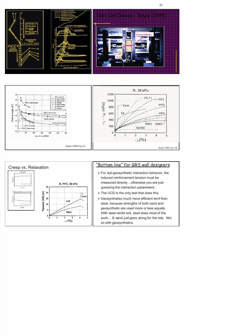
Unit Cell Device – Boyle (1995)
Geosynthetic
Soil
Boyle (1995) Fig. 6.5Boyle (1995) Fig. 6.9b
Creep vs. Relaxation“Bottom line” for GRS wall designers
For soil-geosynthetic interaction behavior, the
induced reinforcement tension must be
measured directly otherwise you are just
24

8/11/2019 2011 Buchanan Lecture-Cold War Legacy Design Costruction and Performance of a Land_Based Radioactive Waste Disposal Facility-Bonaparte
http://slidepdf.com/reader/full/2011-buchanan-lecture-cold-war-legacy-design-costruction-and-performance-of 25/56
“Bottom line” for GRS wall designers...
Creep of GRS “walls” not really a problem at working
stresses. When loading stops, GRS deforms as the
geosynthetic relaxes. The GRS system is atequilibrium and no longer moves.
Also shown by field measurements of real GRS walls
[Rainier Ave wall; Norway steep slope (Fannin and
Herman, 1990; Fannin, 2001)].
If you still think creep is a problem:
Isochronous load vs.strain curves --Geogrid (after McGown)
Unconfined creep test
In-soil creep rate??
= 114 yr 120 yr
• See Bob Koerner, Grace Hsuan, and Scott Thornton• Use Isochronous load vs. strain curves and time-
temperature superposition; stepped isothermal
method (SIM) Analysis -- ASTM D 6992
• Use BS 8006 (10 000 hr data 120 yr)
• Jon Fannin: BS8006 procedure and AASHTO with
RF CR same T al !
• Finer grained backfills???? ( Avoid if possible…)
If you still think creep is a problem:
My plan:
1. Introduction
2. Reinforced soil—a historical perspective
Things we need still need to know and do:1. Technical
GRS is quite mature... but we could use:
• A simpler (“poor-man’s”) PS device with
Thi d till d t k d d
25

8/11/2019 2011 Buchanan Lecture-Cold War Legacy Design Costruction and Performance of a Land_Based Radioactive Waste Disposal Facility-Bonaparte
http://slidepdf.com/reader/full/2011-buchanan-lecture-cold-war-legacy-design-costruction-and-performance-of 26/56
Things we need still need to know and do:2. Professional issues
1. Too many failures! Most due to• Poor quality backfill• Poor drainage; saturated backfill• Construction problems• Inadequate global or external stability• Unexpected surcharges• …and…
2. Disconnect between wall designer, geotech ofrecord, and site civil
…complicated by wall designs supplied bymaterials suppliers and distributors
Things we need still need to know and do:2. Professional (cont.)
3. Other problems• Lack of proper inspection
• No control of construction by designer
• Economic pressures
• “Value engineered” or “contractor supplied” designs, withno $$ for checking alternates by competent professionals
• Poor training for workers
Question: Is liability avoided by use of vendor-supplieddesigns?
– If not, then why give away billable design hours?
Fixing problems always more expensive than properinspection and control by the designer…
Things we need still need to know and do:
2. Professional (cont.)4. Jurisdictions that require a GRS “wall”
design to be stamped by a registeredstructural engineer (who usually knowsnothing about soil reinforcing andgeosynthetics, and only a little about soils anddrainage issues…and they are not responsible
for construction inspection).
The result? Too many failures! Costly,
potentially tragic, and not acceptable!
• How to fix this current state of affairs?G-I? ASFE? IGS? ISSMGE?
Us as individuals?
• Many of these issues are not unique to GRS
• But they threaten a wonderful technology
…and a wonderful profession
Outline1. Intro
2. Acknowledgements
26

8/11/2019 2011 Buchanan Lecture-Cold War Legacy Design Costruction and Performance of a Land_Based Radioactive Waste Disposal Facility-Bonaparte
http://slidepdf.com/reader/full/2011-buchanan-lecture-cold-war-legacy-design-costruction-and-performance-of 27/56
Colorado – Bob Barrett
Austin, Texas
Tijuana, Mexico
Colorado
Taiwan
R d l h B Ph D P E NAE
27

8/11/2019 2011 Buchanan Lecture-Cold War Legacy Design Costruction and Performance of a Land_Based Radioactive Waste Disposal Facility-Bonaparte
http://slidepdf.com/reader/full/2011-buchanan-lecture-cold-war-legacy-design-costruction-and-performance-of 28/56
Rudolph Bonaparte, Ph.D., P.E., NAE
Rudolph (Rudy) Bonaparte received a B.S. in civil engineering from the University of Texas at Austin
(1977) and an M.S. (1978), and Ph.D. (1981) in geotechnical engineering from the University of California,
Berkeley, where he studied as a National Science Foundation Graduate Research Fellow. For the past
25 years, he has been a Principal at Geosyntec Consultants, Inc., serving as President and CEO for the
past 15 years. Geosyntec is an employee-owned 800-person consulting and engineering firm practicing
in the environmental, geotechnical, water resources, and structural engineering disciplines.
Dr. Bonaparte has focused his professional engineering practice in the areas of geotechnical and
geoenvironmental engineering; geological hazard evaluation and mitigation; and solid, hazardous, and
low-level radioactive waste disposal facility design, permitting, and performance evaluation. He is the
author or co-author of more than 50 peer-reviewed technical papers, several book chapters, and six
major reports published by the U.S. Environmental Protection Agency, Federal Highway Administration,
and U.S. Navy on topics related to his practice specialties. He has served on the editorial boards of the ASCE Journal of Geotechnical and Geoenvironmental Engineering , the journal Geosynthetics
International , and the on-line International Journal of Geoengineering Case Histories . He is a registered
professional engineer in 17 states, a Diplomate of the ASCE Geo-Institute Academy of Geo-
Professionals, and a Board Certified Environmental Engineer by the American Academy of
Environmental Engineers. In 2002, he served on the Board of Governors of the ASCE Geo-Institute.
Dr. Bonaparte was elected to the U.S. National Academy of Engineering (NAE) in 2007. In 2006 he was
elected to the U.T. Austin CAEE Academy of Distinguished Alumni and in 2004 he was selected as
Engineer of the Year by the Georgia Alliance of Professional Engineering Societies. He is co-recipient of
th 2000 J J C M d l f ASCE th 1994 IGS A d f th I t ti l G th ti
The Nineteenth Spencer J Buchanan Lecture
28

8/11/2019 2011 Buchanan Lecture-Cold War Legacy Design Costruction and Performance of a Land_Based Radioactive Waste Disposal Facility-Bonaparte
http://slidepdf.com/reader/full/2011-buchanan-lecture-cold-war-legacy-design-costruction-and-performance-of 29/56
The Nineteenth Spencer J. Buchanan LectureTexas A&M University
November 11, 2011
COLD WAR LEGACY - DESIGN, CONSTRUCTION, AND PERFORMANCE OF A
LAND-BASED RADIOACTIVE WASTE DISPOSAL FACILITY
by
Rudolph Bonaparte,1
John F. Beech, Leslie M. Griffin, and David K. Phillips,2
Beth A. Gross, Brandon Klenzendorf, and Lindsay O’Leary3
ABSTRACT
A mixed low-level radioactive waste (LLRW) and Resource Conservation and Recovery Act (RCRA) waste on-site disposal facility
(OSDF) was constructed as part of the remediation of the U.S. Department of Energy Feed Material Production Center in Fernald,
Ohio. The 56-acre OSDF is fully constructed, filled with waste, and closed. Post-closure monitoring is ongoing. This paper presents
the design, construction, and performance of the OSDF. Waste acceptance criteria and waste placement requirements are described.
Results from three sets of pre-design field and laboratory investigations are summarized. Currently available performance data for the
OSDF’s leachate collection system and leakage detection system are reported. Post-closure monitoring activities are briefly described.The value of this case study is in providing a detailed framework for the conceptual and detailed design of land-based disposal
facilities for mixed LLRW and RCRA waste.
INTRODUCTION
This paper describes the background to, and design,construction, and performance of, a mixed low-level
radioactive waste (LLRW) and Resource Conservation and
Recovery Act (RCRA) waste on-site disposal facility (OSDF)
at the U.S. Department of Energy (DOE) former Feed Material
Production Center (FMPC) in Fernald, Ohio. The main focus
of the paper relates to the approach developed by the authors
to design the OSDF to achieve the DOE design life criterion of
“1,000 years, to the extent reasonable and in any case for 200
years.” Conventional RCRA land disposal facilities for both
municipal and hazardous wastes typically consider a design
life in the range of 50 to 100 years. The paper also highlights
field and laboratory studies conducted in support of design,
construction of the facility, and information generated to date
on facility performance
OSDF background information, and OSDF performance data
that have become available since preparation of the 2008
paper.
HISTORICAL PERSPECTIVE
The U.S. government established the Atomic Energy
Commission (AEC) in 1946 shortly after the end of World
War II. The AEC was given responsibility by Congress for
the peaceful development of atomic energy and also for
developing the country’s nuclear weapons arsenal, taking over
these responsibilities from the wartime Manhattan Project.
From 1946 through 1991, development of America’s nuclear
arsenal was conducted against the backdrop of the “Cold
War”, the political, military, and economic competition and
conflict between the “communist world”, led by the Soviet
Union, and the “western world”, led by the U.S. A few of the
key events of the Cold War and the years in which they
Table 1 Select dates in the Cold War between western
FERNALD SITE AND OSDF BACKGROUND
29

8/11/2019 2011 Buchanan Lecture-Cold War Legacy Design Costruction and Performance of a Land_Based Radioactive Waste Disposal Facility-Bonaparte
http://slidepdf.com/reader/full/2011-buchanan-lecture-cold-war-legacy-design-costruction-and-performance-of 30/56
Table 1. Select dates in the Cold War between western
and communist countries, 1946-1991.
Through the AEC, and then DOE starting in 1977, the country
developed 21 major facilities in 13 states, plus a number of
smaller facilities, to perform research, production, assembly,
and testing related to the U.S. nuclear weapons arsenal. This
group of facilities became known as America’s “nuclearweapons complex”. Table 2 summarizes information about
the major facilities in the complex. The facility that is the
subject of this paper is the Fernald FMPC, discussed below.
Table 2. Major facilities in Cold War U.S. nuclear
weapons complex.
(www.em.doe.gov/pdfs/pubpdfs/linklegacy.aspx)
Step Process Major Sites1 Uranium Mining,
Milling, andRefining
Fernald, Middlesex, WeldonSprings, Oak Ridge,Portsmouth, Paducah, uranium
mining and milling sites
2 Isotope Separation Oak Ridge, Paducah,Portsmouth, Savannah River
3 Fuel and TargetFabrication
Savannah River, Fernald,Ashtabula, Hanford, Oak Ridge
4 Reactor Operations Hanford, Savannah River
5 ChemicalSeparations
Hanford, Savannah River, Idaho NEL
6 WeaponsComponentFabrication
Rocky Flats, Hanford, LosAlamos, Oak Ridge, Mound,Savannah River
7 Weaponsi
Pantex, Oak Ridge, Mound,i i ll di
FERNALD SITE AND OSDF BACKGROUND
INFORMATION
The DOE FMPC was located on a 1,050-acre site in Fernald,
Ohio, approximately 18 miles northwest of downtown
Cincinnati. From 1951 to 1989, the facility was used for the
processing of uranium ore to produce uranium intermediate products (i.e., uranium trioxide [UO3] and uranium
tetrafluoride [UF4]) and high-purity uranium metal (99.3%
U238 and 0.7% U235) for shipment to other sites in the nuclear
weapons complex where the intermediate products and high-
purity metals were further processed to produce nuclear
weapons. Figure 1 shows uranium ore being unloaded at the
Fernald site. Figure 2 shows several of the operating plants at
the site where uranium ore was processed to produce uranium
intermediate products. Some of these intermediate products
were sent to the DOE Paducah (Kentucky) gaseous diffusion
plant for enrichment to produce weapons-grade uranium (i.e.,
uranium highly enriched in the fissile U235 isotope). One of
the principal high-purity metal products produced at Fernald
was machined-metal uranium fuel cores (Figure 3). These
fuel cores were shipped to nuclear reactors at the DOE
Savannah River and Hanford sites for neutron bombardment
to produce weapons-grade plutonium (Pu239). During itsoperating life, the Fernald facility delivered to other facilities
within the DOE complex approximately 190,000 tons of high-
purity machined uranium metal products, and 38,000 tons of
intermediate products, primarily uranium trioxide and uranium
tetrafluoride. Employment at the plant peaked in 1956 at
nearly 2,900 employees, and at the time of shutdown, the
facility contained more than 220 buildings.
Year Event
1946 Churchill “Iron Curtain”
1947 Marshall Plan
1948 Berlin Blockade and Airlift
1950 Korean War
1961 Bay of Pigs, Berlin Wall
1962 Cuban Missile Crisis
1963 Kennedy “Ich bin ein Berliner”
1968 Soviets Crush Czechoslovakian Revolt
1972 Nixon-Brezhnev Détente
1982 Poland Solidarity
1986-1988 Reagan-Gorbachev Meetings/Treaties
1987 Reagan “Mr. Gorbachev, tear down that wall”
1990 Germany Reunited
1991 Soviet Union Dissolved
Table 3. Major remediation and restoration projects
30
8/11/2019 2011 Buchanan Lecture-Cold War Legacy Design Costruction and Performance of a Land_Based Radioactive Waste Disposal Facility-Bonaparte
http://slidepdf.com/reader/full/2011-buchanan-lecture-cold-war-legacy-design-costruction-and-performance-of 31/56
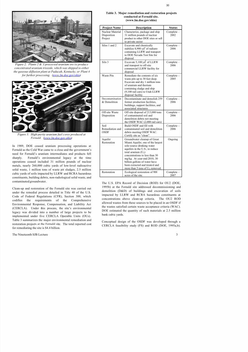
Figure 2. Plants 2 & 3 processed uranium ore to produce
concentrated uranium trioxide, which was shipped to eitherthe gaseous diffusion plant at Paducah, Kentucky, or Plant 4
for further processing. ( www.lm.doe.gov/ohio )
Figure 3. High-purity uranium fuel cores produced at
Fernald. ( www.lm.doe.gov.ohio )
In 1989, DOE ceased uranium processing operations at
Fernald as the Cold War came to a close and the government’s
need for Fernald’s uranium intermediates and products fell
sharply. Fernald’s environmental legacy at the time
operations ceased included 31 million pounds of nuclear
metals, nearly 260,000 cubic yards of low-level radioactive
solid waste, 1 million tons of waste pit sludges, 2.5 millioncubic yards of soils impacted by LLRW and RCRA hazardous
constituents, building debris, non-radiological solid waste, and
contaminated groundwater.
Clean-up and restoration of the Fernald site was carried out
Table 3. Major remediation and restoration projects
conducted at Fernald site.
(www.lm.doe.gov/ohio)
Project Name Description Status
Nuclear Material
DispositionProject
Characterize, package and ship
31 million pounds of nuclear product to other DOE sites or sellto private sector
Complete –
2002
Silos 1 and 2 Excavate and chemicallystabilize 8,900 yd3 of radium-containing LLRW and transportto DOE Nevada Test Site fordisposal
Complete –2006
Silo 3 Excavate 5,100 yd of LLRWand transport to off-site
commercial LLRW facility fordisposal
Complete –2006
Waste Pits Remediate the contents of sixwaste pits up to 30 feet deep.Excavate and dry 1 million tonsof uranium and thorium
containing sludge and ship(9,100 rail cars) to Utah LLRWdisposal facility
Complete –2005
Decontamination
& Demolition
Decontaminate and demolish 259
former production facilities, buildings, support facilities, andassociated structures
Complete –
2006
Off-site WasteDisposition
Off-site disposal of 213,000 tonsof contaminated soil anddemolition debris not meetingthe OSDF WAC (2,000 rail cars)
Complete –2006
SoilRemediation andOSDF
Build OSDF and fill withcontaminated soil and demolitiondebris meeting OSDF WAC.
Certify site as “clean”.
Complete –2006
AquiferRestoration
Groundwater cleanup of GreatMiami Aquifer, one of the largestsole-source drinking wateraquifers in the U.S., to reducetotal uranium (UT)concentrations to less than 30mg/kg. At year-end 2010, 30
billion gallons of water have been extracted and treated andmore than 5 tons of UT removed.
Ongoing
Restoration Ecological restoration of 900acres of the site.
Complete –2007
The U.S. EPA Record of Decision (ROD) for OU2 (DOE,
1995b) at the Fernald site addressed decommissioning and
demolition (D&D) of buildings and excavation of soils

8/11/2019 2011 Buchanan Lecture-Cold War Legacy Design Costruction and Performance of a Land_Based Radioactive Waste Disposal Facility-Bonaparte
http://slidepdf.com/reader/full/2011-buchanan-lecture-cold-war-legacy-design-costruction-and-performance-of 32/56
TABLE 4. Geotechnical characteristics of soil units Note: Information summarized from Parsons, 1995.
32

8/11/2019 2011 Buchanan Lecture-Cold War Legacy Design Costruction and Performance of a Land_Based Radioactive Waste Disposal Facility-Bonaparte
http://slidepdf.com/reader/full/2011-buchanan-lecture-cold-war-legacy-design-costruction-and-performance-of 33/56
underlying OSDF.
Unit and Description
Liquid Limit/
Plasticity
Index (ranges)
Gravel/Sand/
Silt/Clay
(%)
Brown Till:Predominantly siltylow-plasticity clay (CL),with pockets of high
plasticity clay (CH) and
silt (MH), pockets ofclayey sand (SC),contains scatteredgravel (k=1 ! 10
-8 –
6 ! 10-6
cm/s).
21 – 50/
7 – 32
0 – 20/1 – 40/
30 – 60/20 – 60
Gray Till:Predominantly sandylean clay (CL) withlenses and pockets ofsand (SW), and clayeysand (SC), containsscattered gravel(k=1 ! 10
-8 – 3 ! 10
-8
cm/s).
19 – 33/5 – 7
0 – 31/1 – 39/
28 – 79/18 – 58
Great Miami Aquifer:Sand and gravelmixtures, very stiff tohard.
NP
0 – 35/57 – 91/4 – 10/0 – 3
Hydraulic conductivity (k) values for till soils obtained for
Shelby tube samples tested in accordance with ASTM D 5084.
Radiological fate and transport modeling performed as part of
the FS resulted in a requirement that at least 12 ft. of
undisturbed gray till be left in place below the OSDF tofunction as both a hydraulic barrier and geochemical barrier to
potential downward migration of radiological waste
constituents. The gray till was not penetrated in construction
of the OSDF, thereby meeting this requirement (Figure 8).
WASTE CHARACTERISTICS
Materials disposed in the OSDF consist of about 85 percent
soil and soil-like materials (SLMs) excavated as part of the
remediation of the Fernald site and about 15 percent building
demolition debris, structural members, mass concrete,
decommissioned equipment, lime sludge, coal flyash,
municipal solid waste, asbestos waste, and small quantities of
other materials.
OSDF waste acceptance criteria (WAC) for radiological and
hazardous constituents in soil are given in Table 5. Thesecriteria were established during the FS through fate and
transport modeling of leaching and leakage scenarios from the
OSDF to groundwater. If waste materials at the Fernald site
exceeded any of these criteria, the waste could not be placed
in the OSDF.
33

8/11/2019 2011 Buchanan Lecture-Cold War Legacy Design Costruction and Performance of a Land_Based Radioactive Waste Disposal Facility-Bonaparte
http://slidepdf.com/reader/full/2011-buchanan-lecture-cold-war-legacy-design-costruction-and-performance-of 34/56
TABLE 5. OSDF radiological and hazardous constituent
waste acceptance criteria for soil.
Constituents of Concern
(COCs)
Maximum
Concentrations
Radionuclides:
1 Neptunium-237 3.12 ! 10 pCi/g
2 Strontium-90 5.67 ! 10 pCi/g 3 Technetium-99 29.1 pCi/g
4 Uranium-238 346 pCi/g
5 Total Uranium 1,030 mg/kg
Inorganics:
6 Boron 1.04 ! 10 mg/kg
7 Mercury 5.66 ! 10 mg/kg
Organics:
8 Bromodichloromethane 9.03 ! 10-
mg/kg 9 Carbazole 7.27 ! 10 mg/kg
10 Alpha-chlordane 2.89 mg/kg
11 Bis(2-chloroisopropyl)ether 2.44 ! 10-2
mg/kg
12 Chloroethane 3.92 ! 10 mg/kg
13 1 1-Dichloroethene 11 4 mg/kg
The OSDF also had a large number of physical WAC,
including for example:
•
concrete structural members could not be more than 10 ft.long nor more than 18 in. thick and 4 ft. wide;
• reinforcing bars protruding from concrete debris were cut
to within 12 in. of the concrete;
• metal structural members could not be more than 10 ft.
long nor more than 18 in. thick and 10 ft. wide;
•
building rubble, HVAC components, electricalequipment, and mechanical equipment needed to be size
reduced to less than 18 in. thick;
• process piping with a diameter larger than 12 in. was split
in half; and
•
all equipment was drained of oil and other liquids prior todisposal.
In addition to the physical WAC given above, soil and SLMs
brought to the OSDF had to have moisture contents thatallowed the materials to be compacted to required levels using
standard soil compaction equipment and procedures. As
necessary, soil and SLMs were dried by disking and air
drying, or by blending with drier soil.
Figure 8. OSDF north-south cross section. Vertical exaggeration = 10x
SLM finer than 1 in. particle size. These impacted materials
bl i d d il i i
be placed and compacted, were filled with flowable sand or
i k if f C i l d
34

8/11/2019 2011 Buchanan Lecture-Cold War Legacy Design Costruction and Performance of a Land_Based Radioactive Waste Disposal Facility-Bonaparte
http://slidepdf.com/reader/full/2011-buchanan-lecture-cold-war-legacy-design-costruction-and-performance-of 35/56
were compactable using standard soil compaction equipment.
Category 1 material was placed in 12 to 15 in. loose lifts and
compacted to a minimum standard Proctor (ASTM D 698)
relative compaction (SPRC) of 90 percent using Caterpillar
815 or 825 soil compactors.
Category 2 impacted materials were materials that could be
transported, placed, spread, and compacted en masse. These
materials could be spread in loose lifts of 21 in. ±3 in. thick
and were compacted using a Caterpillar 826 landfill
compactor or approved similar equipment. Examples of
Category 2 materials include broken-up concrete foundations
and impacted soil mixed with broken-up concrete. This
category also included general building rubble and debris of
irregularly shaped metals and other components of the
superstructure or substructure with a maximum length of 10 ft.
and a maximum thickness of 18 in. Category 2 material was
placed at designated grid locations in areas with lateral
dimensions not exceeding 100 ft. Each compacted lift of
Category 2 material was covered with at least 4 ft. of Category
1 material. Placement of Category 2 material is shown in
Figure 9.
Figure 9. Typical grid system for placement of impacted
material, with Category 2 material being placed in the center
of the photograph. Placards were used to identify the grids to
facilitate placement and construction documentation. Cell stormwater catchment area is also visible in upper-center
portion of photograph.
Category 3 impacted materials were materials that had to be
individually handled and placed in the OSDF, and that were
quick set grout. Lifts of Category 3 material were separated
vertically by at least 4 ft. of compacted Category 1 material.
Category 4 impacted materials were high in organic content
and/or prone to decomposition. Examples of these materials are
municipal solid wastes from an on-site solid waste landfill, andgreen waste from clearing, stripping, and grubbing operations
around the Fernald facility. Category 4 material was placed at
designated grid points in loose thicknesses of not more than 18
in. and lateral dimensions of not more than 100 ft. This material
was compacted with the landfill compactor or large dozer. Not
more than two lifts of Category 4 material could be placed at a
grid location. Subsequent grid locations were not allowed to be
placed in the vertical space above previously-placed Category 4
grids.
Category 5 impacted materials were materials that require
special handling due to their specific nature. Examples of these
materials include double-bagged asbestos, piping with asbestos
containing material, and sludges. Each of these materials had
customized placement procedures.
A 3-ft. thick “select layer” of compacted Category 1 soil was
placed on top of the liner system to protect the liner during
placement of other categories of waste. Similarly, a 3-ft. thick
soil “select layer” was placed above the OSDF waste mass just
prior to cover system installation for the purpose of protecting
the cover system. These select layers are shown in Figures 11
and 14. The select layer above the liner system was
compacted lightly so as to not damage the liner system (i.e., to
about 85 percent SPRC). Select impacted material below the
cover system was compacted to 90 percent SPRC.
The overall philosophy for waste placement within the
envelope of the select layers was to create a relatively
homogenous mass at a large scale by the controlled placement
of heterogeneous materials at a smaller scale. This was
achieved by using impacted soil and SLMs to form the overall
matrix of the waste mass and distributing heterogeneous
materials such as structural members, dismantled machinery,
and double-bagged asbestos at discrete grid locations both
laterally and vertically throughout the soil/SLM matrix.
As part of the design, short-term and long-term settlements
were estimated for the OSDF foundation and the OSDF waste
mass To obtain these estimates the waste mass was modeled
compression of the impacted materials and settlement of the
f d ti M i t t l ttl t f th t
Conceptual Design Approach
35

8/11/2019 2011 Buchanan Lecture-Cold War Legacy Design Costruction and Performance of a Land_Based Radioactive Waste Disposal Facility-Bonaparte
http://slidepdf.com/reader/full/2011-buchanan-lecture-cold-war-legacy-design-costruction-and-performance-of 36/56
foundation. Maximum total settlements of the cover system
are estimated to be about 3.5 ft. Calculated differential
settlements for both the liner system and cover system resulted
in acceptable post-settlement grades and geosynthetic
tensions, with adequate factors of safety.
OSDF DESIGN
Functional Requirements
Table 6 presents select OSDF functional requirements (i.e.,
essentially performance and design criteria) developed by
DOE that derive from relevant federal and state regulations,
from siting criteria, and from engineering designconsiderations. The design approach used for the OSDF was
developed to achieve these functional requirements.
TABLE 6. Select functional requirements for Fernald
OSDF.
Functional Requirements
Location (exclusions) •
within 200 ft. laterally of stream, lake, or wetland• within 15 ft. vertically of the uppermost aquifer• within a regulatory floodplain• within an area of potential subsidence• within 200 ft. laterally of a Holocene fault
Layout • locate on east side of site, between main facility and power
transmission lines• achieve capacity of 2.5 million bank cubic yards
(ultimately 2.95 million in place cubic yards)•
maximum height should be less than 70 ft. above originalground (visual impact)• final cover system slopes must be between 5 and 25
percent• liner system must overlie at least 12 ft. thickness of
undisturbed gray till• LCS drainage slope must be at least 2 percent
Engineering • design life of 1,000 years to the extent reasonably
achievable, and, in any case, at least 200 years• long-term static slope stability factors of safety (FS) must
exceed 1.5• pseudo-static FS for 2,300-year recurrence interval
earthquake must exceed 1.0• double-liner system with secondary composite liner must
be installed beneath waste• secondary liner must include 3-ft. thick CCL with
maximum hydraulic conductivity of 1 ! 10-7 cm/s overlain
The function of the OSDF is to isolate impacted material from
the environment “for up to 1,000 years to the extent
reasonably achievable, and, in any case, for 200 years.” This
performance criterion was adopted by DOE from 40 CFR
§192.02(a) which provides minimum federal disposal criteriafor uranium and thorium mill tailings. The design was also
developed using the radiation protection goal of DOE Order
5400.5, which requires application of “As Low As Reasonably
Achievable (ALARA)” principles to activities involving the
excavation, transportation, and disposal of LLRW (DOE,
1989). These criteria were achieved in design by addressing
five potential mechanisms for OSDF performance failure:
internal hydrologic control – provide leachate containmentand collection within the OSDF to prevent OSDF leachate
from entering the environment;
external hydrologic control – provide resistance to external
hydrologic impacts, including infiltration through the cover
system and damage by surface-water runon and runoff;
geotechnical stability – provide adequate OSDF slope and
foundation stability during construction, filling, closure, and
post-closure, including conditions associated with potential
long recurrence-interval earthquake events;
erosional stability – provide resistance to erosion of OSDF
soil layers to achieve minimal erosional impacts throughout
the performance period; and
biointrusion resistance – provide resistance to OSDF intrusion
by plant roots and burrowing animals.
Appendix A summarizes the way in which specific design
elements were used to address the potential for OSDF
performance failure.
The OSDF design approach incorporated the following
additional measures to satisfy the performance period:
Natural (i.e., geological) materials were used in preference to
manufactured (i.e., geosynthetic) materials for certain
functions (e.g., internal drainage layers).
Relatively thick compacted-clay liners (CCLs) were
incorporated into the design of both the liner and cover
Rowe, 2005) indicate that at an ambient ground temperature of
about 55°F (12°C) the design life for buried HDPE
collection system (LCS) and leakage detection system (LDS)
are maintained as necessary as is the cover system The cover
36

8/11/2019 2011 Buchanan Lecture-Cold War Legacy Design Costruction and Performance of a Land_Based Radioactive Waste Disposal Facility-Bonaparte
http://slidepdf.com/reader/full/2011-buchanan-lecture-cold-war-legacy-design-costruction-and-performance-of 37/56
about 55 F (12 C), the design life for buried HDPE
geomembranes will be on the order of 1,000 years.
Regulations required the HDPE geomembrane to be at least 60
mil thick. However, the design specified that the
geomembrane be at least 80 mil thick as another measure to
increase the service life of this material. The rationale for thethicker material is that the primary degradation processes for
HDPE geomembrane involve polymer chain oxidation that
starts at the surface and works inward. In the event of surface
oxidation, a thicker material will retain its properties longer
than a thinner material, all other factors being the same. The
specifications also required the HDPE formulation to contain
2 to 3 percent antioxidant-containing carbon black (ASTM D
1603) and to have a minimum environmental stress crack
resistance (ESCR) of 500 hours when tested in accordance
with the notched constant tensile load (NCTL) method of
ASTM D 5397. In 1995, HDPE geomembrane specifications
typically required ESCR of 100 to 200 hours; the more
stringent specification for the OSDF provides a material with
better aging potential and less potential for long-term brittle
rupture under stress.
All hydraulic barriers in the liner and cover systems (primaryliner, secondary liner, and cover barrier layer) were designed
as soil-geosynthetic composite barriers in preference to single
component barrier layers. Composite barriers provide
superior hydraulic containment compared to single-component
barriers (Giroud and Bonaparte 1989a, b). The individual
components of composite barriers also help to protect the
other component. For example, CCLs provide good bedding
layers for geomembranes and geomembranes help to prevent
desiccation cracking of CCLs after installation.
For design, the OSDF performance period was divided into
three operating timeframes.
Initial Period. The initial period extends from construction
until the end of the 30-year post-closure monitoring period
described in the OSDF ROD [DOE, 1995b]. During this
period, leachate generation rates are predicted to decrease
from a design value at the start of cell filling of 1,150 gallons
per acre of lined area per day (gpad) to only 0.002 gpad at the
end of the post-closure period (Geosyntec, 1997b). These
values are based on a mean annual precipitation of 40 in. and
they were estimated using the U.S. EPA computer model
are maintained as necessary, as is the cover system. The cover
system is planted with a variety of native prairie grasses that
require periodic mowing and baling to simulate periodic grass
fires. This periodic mowing will also prevent the growth of
trees on the cover system during this period.
Final Period. The final period does not occur for at least 200
years, and possibly up to 1,000 years, after final closure of the
OSDF. During this period, natural earth components of the
liner and final cover systems continue to be functional. It is
assumed that, at some point in time, the HDPE geomembrane
and other geosynthetic components of the liner and cover
systems begin to degrade and progressively lose functionality.
Responsibility for maintenance and stewardship for the OSDFrests in perpetuity with the U.S. government. The OSDF
design allows government decision makers at the time of the
final period to select an appropriate continuing management
strategy for the facility. Potential strategies include:
Ending Maintenance. Any small amount of leachate
generated by the OSDF (due to infiltration through the
degraded OSDF cover system) will be allowed to migrate
through the degraded liner system into the brown and gray till
that underlies the OSDF. In this case, the LCS and LDS drain
pipes from each cell will be sealed by grouting or other
appropriate measures. Based on the studies performed for the
OU2 FS [DOE, 1995a], this final period management
approach will be protective of groundwater quality in the
underlying Great Miami aquifer.
Continuing Maintenance. The cover system and LCS andLDS drain pipes will be maintained. While no leachate is
expected under this scenario, any LCS or LDS drainage will
be collected and transported off-site for treatment, or
discharged to a natural treatment system, such as a wetland
area established at or near the site, the selected treatment
approach will depend on the quality and quantity of the
draining liquids.
Reconstruction/Rehabilitation. The cover system and LCSand LDS drain pipes will be reconstructed/rehabilitated using
the most appropriate technologies available at that time, or
other improvements will be made to the facility based on
technologies that have emerged since OSDF construction.
37

8/11/2019 2011 Buchanan Lecture-Cold War Legacy Design Costruction and Performance of a Land_Based Radioactive Waste Disposal Facility-Bonaparte
http://slidepdf.com/reader/full/2011-buchanan-lecture-cold-war-legacy-design-costruction-and-performance-of 38/56
herringbone pattern at a 2 percent slope to drain leachate by
gravity to the west side of the cell. This grading configuration
was designed to follow the pre-construction natural grades in
the project area, thereby limiting foundation excavation
requirements. Maximum excavation depth for the OSDF was
15 ft. at the northeast corner of Cell 1, but the average
excavation depth was only a few feet. This configuration
allows the LCS and LDS drainage pipes to exit the cell at or
near the original ground surface elevation. While the basegrading plan for each cell is similar, the elevations of the
grades step down from Cell 1 to Cell 8, again to follow pre-
construction natural grades in the project area, thereby limiting
cut and fill volumes.
Figure 11 shows the liner system configuration for the OSDF.
The double-composite liner system is constructed of a
combination of hydraulic barrier layers, drainage layers, and
filter and cushion geotextiles. Gravel was specified for theLCS and LDS drainage layers in preference to geosynthetics
due to design life considerations. The gravel had a maximum
particle size of 0.75 in. and less than 2 percent fines (Figure
12). Durability considerations also drove selection of the
HDPE geomembranes The durability characteristics of the
Figure 11. OSDF double-composite liner system: A =
primary liner system; B = secondary liner system; C =
leachate removal pipe (perforated in cell and solid, double-
Figure 10. OSDF east-west cross section.
(6.6-in. outside diameter pipes having a standard dimension
ratio (SDR) of 11, meaning the pipe wall thickness is 0.6 in.).
(Figure 13), rather than the one pipe that is customarily used
in landfill applications.
38

8/11/2019 2011 Buchanan Lecture-Cold War Legacy Design Costruction and Performance of a Land_Based Radioactive Waste Disposal Facility-Bonaparte
http://slidepdf.com/reader/full/2011-buchanan-lecture-cold-war-legacy-design-costruction-and-performance-of 39/56
ratio (SDR) of 11, meaning the pipe wall thickness is 0.6 in.).
In consideration of the OSDF design life, all LCS/LDS pipes
gravity drain from the cells to a double-walled collection
forcemain located in valve houses outside each cell (Figure
10). Gravity drainage was judged to be a more reliable long-
term liquids removal strategy than one using submersible pumps and sideslope riser pipes. This LCS/LDS drainage
strategy did necessitate penetration of the LCS and LDS pipes
through the liner system at the location of the downgradient
perimeter berm. As part of the design, special measures were
developed for sealing the liner system to the penetrating pipes.
This detail is described subsequently. Each LCS/LDS valve
house was designed to contain cleanout connections on the
LCS and LDS removal lines.
Figure 12. Placement of the LCS and LDS gravel drainage
layers included the use of dump trucks operating on a 3-ft
thick access road constructed from gravel and low-ground
pressure dozers to spread the gravel.
Redundant features were incorporated in the liner systemdesign, including a second, back-up LCS liquid removal pipe
in landfill applications.
One unique aspect of the OSDF design is management of
precipitation that falls on an active cell. Standard practice for
MSW landfills is to cover the waste with daily or intermediate
cover (soil or tarps) and direct the collected precipitation awayfrom the landfill as clean storm water. For the OSDF, all
precipitation that fell on an active cell, until at least two layers
of the final compacted clay cap were in place, had to be
collected and treated. To achieve this, a stormwater catchment
area was placed in the southwest corner of each cell.
Collection began immediately after the placement of the
protective soil layer because impacted soil could be used for
this layer. The catchment area was located directly over the
leachate collection layer at the low end of each cell. The
collected impacted storm water drained out the bottom of the
catchment area into the LCS and was managed as leachate.
The catchment area was sized to contain run-off from a 25-
year, 24-hour storm event. As discussed in the performance
section of this paper, this stormwater catchment system may
have contributed to unexpectedly high leachate generation
rates in the OSDF.
Figure 14 shows the configuration of the final cover system.
Final cover slopes are 6 horizontal:1 vertical (6H:1V) on the
sides of the OSDF and 6 percent on the top deck.
Construction of the CCL in the final cover system is shown in
Figure 15. The final cover side slope inclination is flatter than
for most MSW landfills and was chosen based on the results
of slope stability and erosion gullying analyses to achieve the
functional requirements described previously. To maintain the
long-term functionality of the final cover system, the biointrusion layer is designed to arrest plant root and/or
burrowing animal intrusion. Placement of the biointrusion
layer is shown in Figure 16.
39
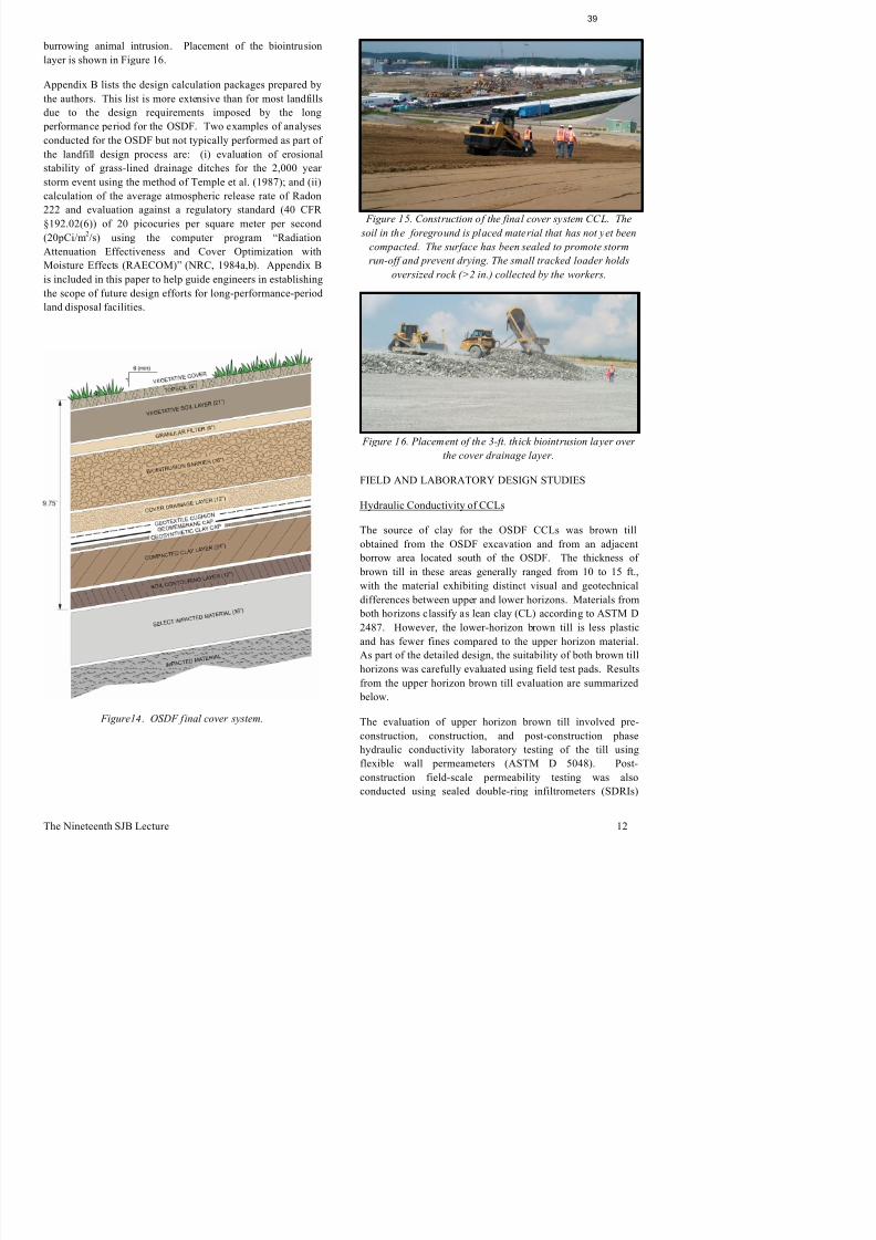
8/11/2019 2011 Buchanan Lecture-Cold War Legacy Design Costruction and Performance of a Land_Based Radioactive Waste Disposal Facility-Bonaparte
http://slidepdf.com/reader/full/2011-buchanan-lecture-cold-war-legacy-design-costruction-and-performance-of 40/56
y g
Appendix B lists the design calculation packages prepared by
the authors. This list is more extensive than for most landfills
due to the design requirements imposed by the long
performance period for the OSDF. Two examples of analysesconducted for the OSDF but not typically performed as part of
the landfill design process are: (i) evaluation of erosional
stability of grass-lined drainage ditches for the 2,000 year
storm event using the method of Temple et al. (1987); and (ii)
calculation of the average atmospheric release rate of Radon
222 and evaluation against a regulatory standard (40 CFR
§192.02(6)) of 20 picocuries per square meter per second
(20pCi/m2/s) using the computer program “Radiation
Attenuation Effectiveness and Cover Optimization with
Moisture Effects (RAECOM)” (NRC, 1984a,b). Appendix B
is included in this paper to help guide engineers in establishing
the scope of future design efforts for long-performance-period
land disposal facilities.
Figure 15. Construction of the final cover system CCL. The
soil in the foreground is placed material that has not yet been
compacted. The surface has been sealed to promote stormrun-off and prevent drying. The small tracked loader holds
oversized rock (>2 in.) collected by the workers.
Figure 16. Placement of the 3-ft. thick biointrusion layer over
the cover drainage layer.
FIELD AND LABORATORY DESIGN STUDIES
Hydraulic Conductivity of CCLs
The source of clay for the OSDF CCLs was brown till
obtained from the OSDF excavation and from an adjacent
borrow area located south of the OSDF. The thickness of
brown till in these areas generally ranged from 10 to 15 ft.,
with the material exhibiting distinct visual and geotechnical
differences between upper and lower horizons. Materials from both horizons classify as lean clay (CL) according to ASTM D
2487. However, the lower-horizon brown till is less plastic
and has fewer fines compared to the upper horizon material.
As part of the detailed design, the suitability of both brown till
horizons was carefully evaluated using field test pads. Results
(ASTM D 5903). Pre-construction laboratory tests were used
to design the field test pad program. The SDRI tests were
of the test pad were obtained at the end of test pad
construction and samples from the tubes were extruded in the
40

8/11/2019 2011 Buchanan Lecture-Cold War Legacy Design Costruction and Performance of a Land_Based Radioactive Waste Disposal Facility-Bonaparte
http://slidepdf.com/reader/full/2011-buchanan-lecture-cold-war-legacy-design-costruction-and-performance-of 41/56
used to assess field construction methods and to establish the
acceptable permeability zone (APZ) for OSDF CCL
construction. The construction and post-construction
laboratory tests were performed to evaluate the quality of thin-
walled tube samples for use in QC/QA during OSDF CCLconstruction. The APZ was defined as those combinations of
compaction moisture content and dry unit weight producing a
CCL with a hydraulic conductivity not greater than 1 ! 10-7
cm/s. The test pad (Figure 17) had six compacted lifts, a
nominal compacted thickness of 3 ft., and three lanes, with
each lane about 14.3 ft. wide (equal to the full pass width of a
Caterpillar 815B padfoot compactor) and 50 ft. long
(excluding end ramps).
Figure 17. Plan view of test pad for upper horizon brown till
(design of test pad for lower horizon brown till was identical).
For the test pad, the target compaction moisture content was
the same for all three lanes at 2 percentage points +/- 1
laboratory and evaluated for hydraulic conductivity in flexible
wall permeameters. The field testing program included
moisture content, dry unit weight, and field hydraulic
conductivity as measured using SDRIs. Two SDRI tests were
performed. For each, a test was performed on the lane with 4compaction passes and a test was performed on a lane with 7
compaction passes. Figure 18 shows an idealization of the
SDRI set-up and Figure 19 shows one of the SDRI tests in
progress. The duration of the SDRI tests was 26 days. At the
conclusion of each test, four thin-walled tube samples were
obtained from within each of the SDRI inner ring areas. Two
of the tubes were used to obtain samples for post-construction
laboratory hydraulic conductivity testing in flexible wall
permeameters, and two were used for interval moisture
content testing to evaluate the advancement of the wetting
front.
Figure 18. Sealed double-ring infiltrometer test set-up.
Figure 19. Sealed double-ring infiltrometer test in progress.
As can be seen in Table 7 stabilized SDRI hydraulic
saturation line to the left, a moisture content equal to 3
percentage points wet of the standard Proctor optimum Moisture
C
Dry
D i
Degree of
S i
Hydraulic
Conductivity
( fi i
Figure
ID N
41

8/11/2019 2011 Buchanan Lecture-Cold War Legacy Design Costruction and Performance of a Land_Based Radioactive Waste Disposal Facility-Bonaparte
http://slidepdf.com/reader/full/2011-buchanan-lecture-cold-war-legacy-design-costruction-and-performance-of 42/56
moisture content to the right, and the 95 percent SPRC at the
bottom.
Figure 20. Acceptable permeability zone for upper horizon
brown till.
TABLE 7. Summary of laboratory and field hydraulic
conductivity test results for upper horizon brown till.
Moisture
Content
(percent)
Dry
Density
(pcf)
Degree of
Saturation
(percent)
Hydraulic
Conductivity
(confining
stress=2 psi)
(cm/s)(3)
Figure
ID No.
(1)
Pre-Construction) - Laboratory Results
16.7 106.3 76.1 5.2 ! 10-
1
17.0 110.9 87.2 6.4 ! 10-
2
18 4 108 3 88 2 8 4 ! 10-
3
Content
(percent)
Density
(pcf)
Saturation
(percent)
(confining
stress=2 psi)
(cm/s)(3)
ID No.
(1)
Construction Phase - Laboratory Results
19.0 111.5 99.6 9.8 ! 10- 25
20.5 107.3 95.8 1.5 ! 10-
26
20.1 110.2 101.2 5.3 ! 10-
29
19.6 108.3 94.0 1.7 ! 10-
30
Post-Construction - Laboratory Results
20.6 106.9 95.3 5.1 ! 10-
27
19.1 109.5 94.5 1.3 ! 10-
28
19.6 109.1 95.9 2.3 ! 10-
31
20.9 105.8 94.1 9.4 ! 10-
32
Notes:
1. Figure ID No. refers to Figure 20.
2. Upper horizon brown till composite sample: LL=43,
PL=20, PI=23; 74% passing #200 sieve; specific
gravity=2.72.
3. Pre-construction laboratory results obtained with flexible
wall falling-head permeameter tests (ASTM D 5084)
using laboratory compacted samples. Construction and post-construction laboratory results obtained using same
tests and thin-wall tube samples obtained from field test pad.
Compatibility of Liner System with Leachate
As part of the detailed design, a literature-based durability
evaluation was undertaken for the geomembrane and soil
components of the liner system. Based on this “desk top”
evaluation, it was concluded that additional data were needed
on the potential for OSDF leachate to affect the properties ofHDPE geomembranes. A leachate-geomembrane
compatibility testing program was developed to fill this data
gap. Five different commercial 80-mil thick HDPE
geomembranes from the four major U.S. manufacturers in
1995 were evaluated using U.S. EPA Method 9090,
“Compatibility Test for Waste and Membrane Liners.” This
method involves submersion of geomembrane samples in test
leachate at 23°C (73°F) and 50°C (122°F) for 120 days.Specimens of the various samples are retrieved at 30, 60, 90,
and 120 days and evaluated against controls for changes in
physical, mechanical, and chemical properties. A detailed
presentation of the leachate-geomembrane compatibility
testing program is contained in Geosyntec (1997c). A brief
TABLE 8. Comparison of OSDF test leachate to Fernald
perched groundwater wells and OSDF modeling results.
performance. The FTIR results did not reveal any indication
of surface oxidation of the geomembranes due to exposure to
h l h ll fi f h b d
42

8/11/2019 2011 Buchanan Lecture-Cold War Legacy Design Costruction and Performance of a Land_Based Radioactive Waste Disposal Facility-Bonaparte
http://slidepdf.com/reader/full/2011-buchanan-lecture-cold-war-legacy-design-costruction-and-performance-of 43/56
Radionuclide
Clarifier Pit
Perched
Groundwater
Concentrations
Modeled
Concentrations
OSDF Test
Leachate
Concentrations
Technetium-
9915.8–6130 56.6 64262
Uranium-234 0.001–25000 – 220000
Uranium-
235/2360.2–2490 – 29000
Uranium-238 0.3–39000 2240 240000
Uranium,
total0.4–436000 6670 582000
Neptunium-
237 0.626(3)
18.6 0.14
Strontium-90 1.01–7.68 37.9 0.33
Notes:
1. Analyses were performed on unfiltered samples.2. All results are in picoCuries per liter (pCi/L) except total
uranium which is in micrograms per liter ("g/L).
3. Neptunium-237 was detected in only one sample.
Radionuclides in the test leachate included alpha, beta, andgamma emitters at significant concentrations. Total uranium
(alpha, gamma) concentrations in the test leachate exceeded
500 mg/L. In Table 8, it can be seen that the concentration of
total uranium in the test leachate exceeds the range of
concentrations in the modeled leachate by almost two orders
of magnitude. Concentrations of neptunium-237 and
strontium-90 in the test leachate are about two orders of
magnitude less than in the modeled leachate. However, basedon the decay frequencies and energies of the various
radionuclides, the test leachate has a radiological activity for
alpha, beta, and gamma emitters about two orders of
magnitude higher than that of the modeled leachate.
Test data interpretation methodology is described in
Geosyntec (1997c) and included statistical comparisons of
means and standard deviations, temporal and temperature
trends, and consistency of trends between related properties.Typical results for stress at yield and for burst strength are
shown in Figures 21 and 22, respectively. The test results
showed negligible to only very minor changes in properties of
the exposed samples compared to the control samples for
mass thickness dimensions specific gravity extractables
the test leachate. All five of the HDPE geomembranes tested
were qualified for use based on radiological compatibility. It
is interesting to note, however, that only four of the five
geomembranes qualified based on the ESCR criterion of 500
hours (ASTM D 5397).
Figure 21. Effect of leachate exposure on HDPE
geomembrane stress at yield.
Figure 22. Effect of leachate exposure on HDPE geomembrane burst strength.
Soil-Geosynthetic Interface Strength and GCL Internal
Strength Shear Testing Program
used to construct the CCLs, and several different internally-
reinforced GCLs. Interface shear test samples were first
k d f k d ti t f 43 d
shear strengths obtained for all of the materials and interfaces
evaluated for the OSDF design. These large-displacement
i t l h t th t d th d i f il
43

8/11/2019 2011 Buchanan Lecture-Cold War Legacy Design Costruction and Performance of a Land_Based Radioactive Waste Disposal Facility-Bonaparte
http://slidepdf.com/reader/full/2011-buchanan-lecture-cold-war-legacy-design-costruction-and-performance-of 44/56
soaked for one week under a seating stress of 43 pounds per
square foot (psf), then consolidated for 48 hours at normal
stresses of 720, 2,900, and 6,500 psf, and then sheared under
the consolidation stress at rates of 0.04 in./minute and 0.004
in./minute. The lowest normal stress (720 psf) used in the test program represents the approximate normal stress acting on
the geomembrane in the final cover system. The higher two
normal stresses used in the program (2,900 and 6,500 psf)
represent those acting on the liner system. The faster shearing
rate represents the default ASTM rate. The slower shearing
rate was selected based on previous testing that had shown
close agreement between test results at this rate and even
slower rate tests designed to achieve fully-drained porewater
conditions. Interestingly, on the basis of seven side by side
sets of tests conducted on this project, peak textured
geomembrane-GCL interface shear strengths were 2 percent
higher at the slower shear rate of 0.004 in./minute compared to
the results at 0.04 in./minute. The slower rate large-
displacement interface shear strengths were on average 6
percent higher than at the ASTM default rate. Several
individual test differences were larger than these averages.
Fresh GCL, geomembrane, and soil specimens were used for
each consolidation stress and shear rate (i.e., no multi-stage
testing). Peak and large-displacement (2 in.) shear resistance
versus displacement parameters were calculated for each test.
Results from the interface tests were used to establish the
conditions (e.g., CCL moisture content and dry unit weight)
under which constructed interfaces would produce shear
strengths meeting or exceeding the interface shear strengths
used to establish the design. This process was conducted forliner system and cover system interfaces under short-term,
interim, and long-term conditions considering both static and
seismic loading. Figure 23 presents test results for the
textured geomembrane to GCL (woven geotextile) interface
for peak conditions and long-term static loading. The design
failure envelope shown in this figure was developed prior to
the interface testing program by using conservative literature
values for interface strength. Using this envelope, a minimumlong-term static slope stability factor of safety (FS) of 1.9 was
calculated. This FS exceeds the project functional
requirement of a minimum peak FS of 1.5. As can been seen
in the figure, the measured interface strengths exceed the
design failure envelope indicating a true long-term static FS
internal shear strengths meet or exceed the design failure
envelope.
Figure 23. Design and measured peak GCL/geomembrane
interface shear strengths, OSDF final configuration.
Notes: Geomembrane I = 80 mil HDPE with spray-applied
texture; Geomembrane II = 80 mil HDPE with blown-film
texture; and GCL woven geotextile against geomembrane in
all tests.
Figure 24. Design and measured large-displacement GCL
internal shear strengths, OSDF final configuration.
CONSTRUCTION
As already noted, the Fernald OSDF was constructedsequentially as eight contiguous cells. Construction of the
first cell (Cell 1) began in May 1997 and closure of the last
cell (Cell 8) was completed in October 2006. The sequence of
activity for each cell essentially involved excavation of topsoil
and brown till to the design base grades; construction of
designated final grades; placement of another 3-ft. thick select
layer and soil contouring layer on top of the Category 1
through 5 waste; installation of the final cover system; topsoil
At the start of construction for Cell 1, brown till was
excavated, and tested for compliance with specifications. As
had been learned in the test pad program the brown till
44

8/11/2019 2011 Buchanan Lecture-Cold War Legacy Design Costruction and Performance of a Land_Based Radioactive Waste Disposal Facility-Bonaparte
http://slidepdf.com/reader/full/2011-buchanan-lecture-cold-war-legacy-design-costruction-and-performance-of 45/56
through 5 waste; installation of the final cover system; topsoil
seeding; and construction of final stormwater management
controls. Contract documents for this work included the
construction plans and specifications and a variety of support
plans, including: Construction Quality Assurance Plan,Impacted Material Placement Plan, Borrow Area Management
and Restoration Plan, Surface Water Management and Erosion
Control Plan, Cultural Resource Unexpected Discovery Plan,
Systems Plan (including leachate management, utilities, site
security, haul roads, decontamination facilities, and
emergency spill response), Groundwater Monitoring Plan, Air
Monitoring Plan, and Post-Closure Care and Inspection Plan.
The OSDF was designed to be constructed from conventionalmaterials used in liner and final cover systems for waste
containment facilities. These materials have established
installation procedures, which provided a level of confidence
in the ability to construct the OSDF to meet the functional
requirements identified in Table 6. Even so, efforts were
made throughout the project to improve the construction
process. Several of the lessons learned and improvements
made during construction are outlined below.
A critical aspect of the project was to always provide
constructed disposal capacity in time to prevent delays in
overall site remediation. During the nine year active life of
the OSDF, cell construction and cell closure occurred
concurrently with impacted material placement. The preferred
construction season in Ohio starts in late April to early May
and continues until mid-November. A full season was
required to construct the multiple layers of a cell’s liner orfinal cover system. Key to maintaining the construction
schedule was the advanced procurement and processing of
materials, including the necessary QC/QA testing. The
procedure used for procurement of geosynthetics and
processing site soils is described below. Early testing was also
used for the granular material used for the various drainage
layers and the biointrusion layer. These procedures were
developed based lessons learned during the first year of
construction.
Geosynthetics (i.e., geomembrane, GCL, and geotextile) were
procured during the winter months preceding the start of the
construction season. This was done to avoid delays that could
had been learned in the test pad program, the brown till
contained significant amounts of oversized material (> 2 in.).
The contractor’s initial plan was to remove oversize particles
by hand. Hand picking was found to be very time consuming
and slowed productivity. This experience led to the decisionto pre-screen the material in the borrow area. Ultimately, soil
processing for a phase of construction was conducted well in
advance of the start of that phase. The processed soil was
stockpiled in 5,000 to 10,000 cubic yard lots, and the required
QC/QA testing was conducted during the processing
operation. This allowed all conformance testing to be
completed prior to the start of construction. Once test results
demonstrated a stockpile met the CCL specification
requirements, it was labeled as suitable for such. Soils not
meeting the specification were reserved for other on-site uses.
Pre-processing and early QC/QA testing of materials was a
key factor in achieving construction schedule milestones.
As noted previously, a critical component of the design
involved the creation of a watertight seal for the three LCS
and LDS pipe penetrations through the liner system of each
cell. Recognizing the importance of the penetrations, a special penetration box, prefabricated from HDPE flat stock, was
developed. A detail of the penetration box is shown in Figure
25 and an actual box prior to installation is shown in Figure
26.
Figure 25. Detail of the penetration box used at LCS and LDS
pipe penetrations.
Installation of the penetration box presented several challenges
due to the detailed sequencing required for pipe installation
outside the cell, earthwork, and CCL construction,
geosynthetics installation and pipe installation inside the cell
is difficult to cut an opening in the geomembrane panel and
align it with the edge of the box. Thus, the geomembrane
installer was allowed the option of welding a geomembrane
through 8, it was conducted over the entire primary liner
surface. The ELLS was conducted on the exposed primary
geomembrane surface prior to placement of the geotextile
45
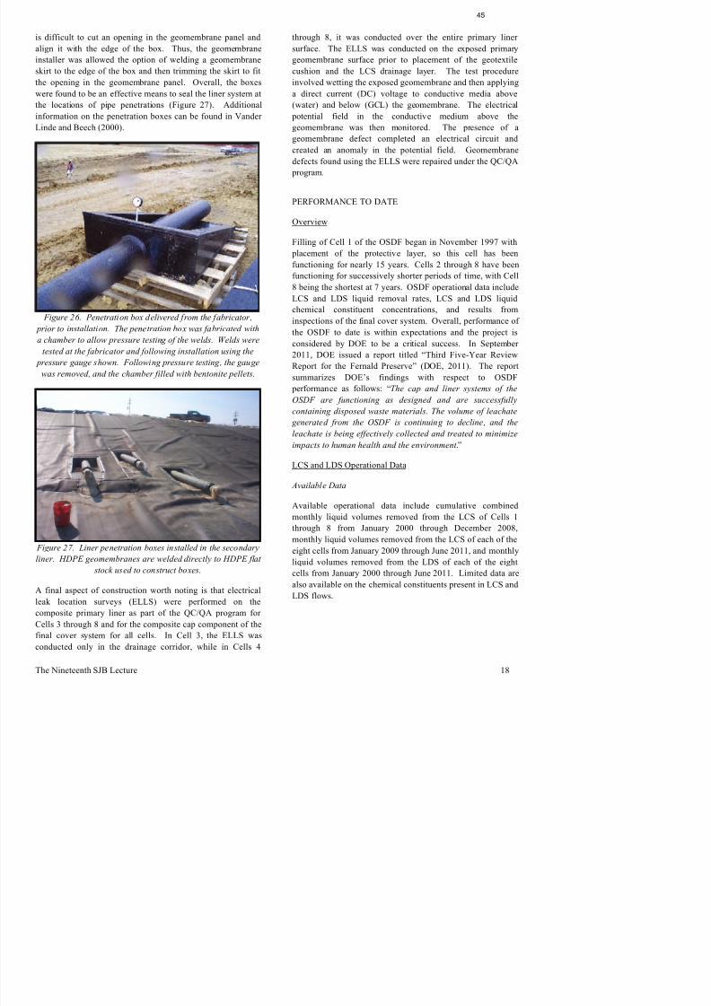
8/11/2019 2011 Buchanan Lecture-Cold War Legacy Design Costruction and Performance of a Land_Based Radioactive Waste Disposal Facility-Bonaparte
http://slidepdf.com/reader/full/2011-buchanan-lecture-cold-war-legacy-design-costruction-and-performance-of 46/56
installer was allowed the option of welding a geomembrane
skirt to the edge of the box and then trimming the skirt to fit
the opening in the geomembrane panel. Overall, the boxes
were found to be an effective means to seal the liner system at
the locations of pipe penetrations (Figure 27). Additionalinformation on the penetration boxes can be found in Vander
Linde and Beech (2000).
Figure 26. Penetration box delivered from the fabricator,
prior to installation. The penetration box was fabricated with
a chamber to allow pressure testing of the welds. Welds were
tested at the fabricator and following installation using the
pressure gauge shown. Following pressure testing, the gauge
was removed, and the chamber filled with bentonite pellets.
Fi 27 Li i b i ll d i h d
geomembrane surface prior to placement of the geotextile
cushion and the LCS drainage layer. The test procedure
involved wetting the exposed geomembrane and then applying
a direct current (DC) voltage to conductive media above
(water) and below (GCL) the geomembrane. The electrical potential field in the conductive medium above the
geomembrane was then monitored. The presence of a
geomembrane defect completed an electrical circuit and
created an anomaly in the potential field. Geomembrane
defects found using the ELLS were repaired under the QC/QA
program.
PERFORMANCE TO DATE
Overview
Filling of Cell 1 of the OSDF began in November 1997 with
placement of the protective layer, so this cell has been
functioning for nearly 15 years. Cells 2 through 8 have been
functioning for successively shorter periods of time, with Cell
8 being the shortest at 7 years. OSDF operational data include
LCS and LDS liquid removal rates, LCS and LDS liquidchemical constituent concentrations, and results from
inspections of the final cover system. Overall, performance of
the OSDF to date is within expectations and the project is
considered by DOE to be a critical success. In September
2011, DOE issued a report titled “Third Five-Year Review
Report for the Fernald Preserve” (DOE, 2011). The report
summarizes DOE’s findings with respect to OSDF
performance as follows: “The cap and liner systems of the
OSDF are functioning as designed and are successfully
containing disposed waste materials. The volume of leachate
generated from the OSDF is continuing to decline, and the
leachate is being effectively collected and treated to minimize
impacts to human health and the environment.”
LCS and LDS Operational Data
Available Data
Available operational data include cumulative combined
monthly liquid volumes removed from the LCS of Cells 1
through 8 from January 2000 through December 2008,
monthly liquid volumes removed from the LCS of each of the
LCS Flow Rates
Leachate generation rates in a typical landfill cell are expected
associated with the occurrence of rainfall events and the
operational status of the various OSDF cells at any point in
time. The very low and high “peakiness” of the measured
46

8/11/2019 2011 Buchanan Lecture-Cold War Legacy Design Costruction and Performance of a Land_Based Radioactive Waste Disposal Facility-Bonaparte
http://slidepdf.com/reader/full/2011-buchanan-lecture-cold-war-legacy-design-costruction-and-performance-of 47/56
to be highest at the start of cell operations (initial stage),
decrease somewhat as the cell is filled (operational stage), and
then decrease still further after cell closure. During the first
few months after the start of waste disposal in a cell (initialstage), there is not sufficient covered waste in the cell to create
grades that can produce runoff and much of the rain that falls
into the cell percolates quickly into the cell LCS. To the extent
rainfall occurs during this period, it will rapidly find its way to
the LCS sump. LCS flow rates during this stage usually
respond quickly to rainfall events. As the cell is progressively
filled with waste (operational stage), some of the incident
rainfall may fall onto covered waste slopes and become
runoff. Some of the rainfall is also absorbed by the significantamount of waste now in the cell and only percolates slowly to
the LCS, if at all. As a consequence, LCS flow rates decrease
during the operational stage compared to the initial stage.
After the cell has been closed with a final cover system,
infiltration of rainwater into the waste is greatly reduced,
resulting in a substantial reduction in LCS flow rates. In
addition to rainwater, other sources of water may contribute to
the production of leachate. As discussed below, anotherimportant source of water in the OSDF was water used for the
suppression of dust during OSDF construction and operations.
LCS flow rates measured for the OSDF from January 2000
through June 2011 are shown in Figure 28 along with
calculated LCS flow rates developed in 1995 during design of
the OSDF. The primary sources of water contributing to
leachate generation in the OSDF have been precipitation and
water used to suppress dust generation during cell operations.The volume of dust suppression water was very significant for
this facility as DOE had strict air quality criteria related to
airborne particulates and radionuclides. The significance of
the dust suppression activities is evidenced by the fact that in
2006, 10.6 million gallons of precipitation fell onto the active
cells of the OSDF while 25.9 million gallons of dust
suppression water were applied in that same year.
Figure 28 was developed by taking the total flow collected
from the LCS for the entire facility and dividing it by the lined
area of the cells that were constructed and contained waste
(active and closed) at the time of the flow measurement. From
Figure 28, it can be seen that the OSDF LCS flow rate was
time. The very low and high peakiness of the measured
LCS flow rates was also affected by the operating schedule for
the leachate transmission system that conveyed leachate from
the OSDF, through the valve houses, to the on-site advanced
wastewater treatment plant.
Figure 28. Measured and design monthly-average LCS flow
rates for OSDF, January 2000 to June 2011.
The measured OSDF LCS flow rates can be compared to the
original design estimates made in 1995 using the U.S. EPA
HELP model. The estimated average annual leachate
generation rates obtained using the HELP model were 1,150
(gpad) for a cell in the initial stage (10 ft thickness of waste),
700 gpad for a cell at the operational stage (30 ft. thickness ofwaste plus soil cover), less than 1 gpad shortly after closure,
and 0.002 gpad at the end of the post-closure period. For the
HELP analysis design estimates reported in Figure 28, for
each month, an area-weighted summation was made of the
HELP-calculated flow rates based on the status of each cell
(i.e., initial stage, intermediate stage, or post closure). From
Figure 28, it can be seen that the leachate generation rates
calculated using actual LCS flow data are significantly higher
than the original design estimates based on the HELP model.
Two project-specific factors have been identified that likely
account for the differences between the design estimates and
actual leachate generation rates: (i) the presence of the
impacted stormwater catchment area in each cell (previously
data for 73 municipal solid waste (MSW) landfill cells and 32
hazardous waste (HW) landfill cells. The LCS data are
evaluated in several ways including as a function of average
rainwater) that infiltrates the LDS during construction and
drains after the start of facility operation (construction water),
water expelled from the LDS during waste placement as a
47

8/11/2019 2011 Buchanan Lecture-Cold War Legacy Design Costruction and Performance of a Land_Based Radioactive Waste Disposal Facility-Bonaparte
http://slidepdf.com/reader/full/2011-buchanan-lecture-cold-war-legacy-design-costruction-and-performance-of 48/56
y g g
annual precipitation. The historical average annual
precipitation in the Fernald vicinity is approximately 40 in.
This rainfall average is closest to the northeast (NE) and
southeast (SE) facility categories in the database. The averageLCS flow rates in the database for the MSW cells in the NE
and SE during the operational stage were 378 and 314 gpad,
respectively, and for the HW cells, 576 and 524 gpad
respectively. These average LCS flow rate results from the
database are somewhat lower than the design values calculated
in 1995 for the OSDF project using the HELP model, and
significantly lower than the measured OSDF intermediate
stage LCS flow rates.
Leachate generation rates after OSDF closure are compared to
rates for other closed landfills in the U.S. EPA database, cited
above, in Figure 29, taken from Bonaparte et al. (2002). This
figure includes data for 11 MSW and 22 HW cells from the
database, plus the 8 OSDF cells. The OSDF data are for 2009,
2010, and the first half of 2011. From the figure, it can be seen
that the post-closure LCS flow rates for the OSDF are
consistent across cells, on the order of 10 gpad, and, so far, notshowing a decreasing trend during the post-closure period.
Figure 29. Average LCS flow rates (gpad) after closure foreleven MSW cells (shown as blue circles), 22 HW cells (shown
as green squares), and the 8 OSDF cells at Fernald (shown as
red diamonds). The OSDF data are for 2009, 2010, and the
first half of 2011. The MSW and HW data are from Bonaparte
et al. (2002).
p g p
result of LDS compression under the weight of the impacted
material (compression water), and infiltration of groundwater
perched in the brown till that finds a pathway through the
secondary composite liner (infiltration water). Gross et al.(1990) provides a detailed discussion of each of these potential
sources along with methods to estimate liquid quantities from
each source given site conditions and facility design details.
At the start of cell operation, much of the LDS flow is often
attributable to construction water. Continuing flow in the
LDS after the construction water has fully drained can be due
to one or several of the sources in Figure 30. Site-specific
analyses using the methods described in Gross et al., coupled
with comparisons of the chemical compositions of the LDS
and LCS flows, allow evaluation of the most likely source(s)
for the LDS flows.
Figure 30. Potential sources of LDS liquids (modified from
Bonaparte and Gross, 1990).
As an illustration of OSDF LDS performance, measured LDS
flow rates for Cell 4 from December 2002, after the cell was
just placed into service, to June 2011, approximately six years
after Cell 4 was closed (April 2005), are shown in Figure 31.
LDS flow rates ranged up to 5 gpad during cell operation then
decreased after the cell was closed. Flow rates are currently
stabilized at less than 0.1 gpad. Figure 31 also shows
measured LCS flow rates for Cell 4 since February 2009.
(LCS flow rates before this time were only available on a
cumulative basis for all cells.) Cell 4 LDS flows since
eight LDSs are producing very low flows, indicating effective
performance of the composite primary liner in all cells.
addition, more limited data are available for a few other
chemical constituents. Average uranium concentrations in the
LCS flows have ranged from approximately 50 to 180 "g/L,
48

8/11/2019 2011 Buchanan Lecture-Cold War Legacy Design Costruction and Performance of a Land_Based Radioactive Waste Disposal Facility-Bonaparte
http://slidepdf.com/reader/full/2011-buchanan-lecture-cold-war-legacy-design-costruction-and-performance-of 49/56
Figure 31. Measured monthly-average LCS and LDS flow
rates for OSDF Cell 4, December 2002 to June 2011.
Figure 32. Monthly-average post-closure LDS flow rates for
the eight OSDF cells.
The measured OSDF LDS flow rates can also be compared to
average LDS flow rates reported in the U.S. EPA database in
Bonaparte et al. (2002). The comparison is made for
operating landfills with geomembrane/GCL composite
primary liners (i.e., the OSDF primary liner). The database
indicates the following typical monthly-average values for
MSW and HW landfills: up to about 30 gpad during the initial
stage, less than 1 gpad during the operational stage, and less
than 0.2 gpad after closure. Inspection of Figure 31 shows
more than three orders of magnitude lower than the
concentration of total uranium in the OSDF test leachate used
for the liner system compatibility test program (Table 8).
Similarly, technetium-99 concentrations in OSDF leachate(typical concentration on order of 10 pCi/L) are three orders of
magnitude lower than the concentration of this parameter in
the test leachate. The much lower radiological activity of the
actual OSDF leachate to the test leachate brings a degree of
conservatism to the interpretation of the results of the
leachate-geomembrane chemical compatibility testing
program described earlier in this paper.
Average total uranium concentrations in the LDS flows fromthe eight ODF cells have been consistent, ranging from 11 to
24 "g/L. LDS uranium concentrations for individual cells
were 3 to 9 times lower than the LCS uranium concentrations
for the same cells. Figure 33, taken from Powell et al. (2011),
shows an example uranium-sodium bivariate plot for the LCS,
LDS, and horizontal till well (HTW, located in the till beneath
the OSDF liner system) liquids for an individual OSDF cell.
The data in Figure 33 indicate that the LCS and LDS flows forthe OSDF cell have distinctly different chemical fingerprints
and the water draining from the cell LDS is not principally
leachate. The very low levels of uranium found in the LDS
may be indicative of several possible sources, including minor
amounts of primary liner leakage, site background
contributions, and/or infiltration of perched groundwater. If
the source is primary liner leakage, the bivariate plot suggests
that the leachate is being diluted by non-leachate sources at a
ratio of 3:1 to 5:1, meaning that only a fraction of the very lowflows from the LDS for the subject cell could potentially be
due to primary liner leakage.
Apparent Leachate Collection Efficiency
2006 shortly after the closure of Cells 7 and 8. While the LCS
flows quickly dropped after closure, the LDS flows responded
more slowly resulting in a temporary drop in ALCE.
49

8/11/2019 2011 Buchanan Lecture-Cold War Legacy Design Costruction and Performance of a Land_Based Radioactive Waste Disposal Facility-Bonaparte
http://slidepdf.com/reader/full/2011-buchanan-lecture-cold-war-legacy-design-costruction-and-performance-of 50/56
To further evaluate the OSDF LCS and LDS flow data,
apparent leachate collection efficiencies, ALCE (percent),
were calculated for the LCS/composite primary liner
(Bonaparte et al., 1996):
ALCE = (1 – LDS Flow Volume/LCS Flow Volume) !
100 (Equation 1)
The cumulative LCS and LDS flow volumes for the entire
facility, and the calculated OSDF facility ALCE, are plotted in
Figure 34.
Figure 34. Cumulative volume of liquid removed from the
LCS and LDS of cells 1 through 8 and calculated facility
ALCE, January 2000 to June 2011.
The calculated ALCE for the OSDF for the period from
January 2000 to June 2011 is 99.8 percent, which is consistent
with efficiencies for composite liners reported by Bonaparte et
al. (2002), and is indicative of a very high level of leachate
containment and collection by, respectively, the composite
primary liner and LCS. This means that the LDS has produced only 0.2 percent of the flow of the LCS. The true
hydraulic efficiency of the composite primary liner in
containing leachate is actually higher than this apparent value
because, as discussed above, it has been shown through the
bivariate plots that the LDS liquids are not principally
However, over time the ALCE values again increased to
greater than 99 percent.
Cover System Erosion and Maintenance
The final cover system for the OSDF is inspected quarterly for
erosion rills/channels, depressions, cracks, ponded water,
seepage, vegetation coverage, presence of woody vegetation,
evidence of biointrusion, and evidence of vehicle traffic. The
final cover system was designed with a maximum calculated
erosion rate of 4.3 tons/acre/year, based on the Modified
Universal Soil Loss Equation (MUSLE). If erosion occurs at
this maximum calculated rate, the thickness of the topsoil andvegetative soil layer of the final cover system will be reduced
from 27 in. to 22 in. after 200 years, and to 3.5 in. after 1,000
years. Design calculations were also performed to evaluate the
potential for rills and gullies to form in the final cover system
during the 2,000-year storm event. Analyses conducted using
the Temple (Temple et al., 1987), Horton/NRC (NRC, 1990),
and permissibly velocity (NRC, 1990) methods indicated that
the formation of rills and gullies would not occur during the
design storm as long as the final cover system was vegetated
with a well-established stand of native grasses. Further, in the
event that erosion of cover soils did occur, the biointrusion
barrier was designed to resist erosion in the 2000-year storm
and probable maximum precipitation (PMP). The Stephenson
(Abt et al., 1988) and Hartung and Scheuerlein (1970)
methods were used to evaluate the stability of the biointrusion
barrier under these design storm events. The analyses indicate
that the biointrusion barrier layer would stop the advancementof gullies in the 2,000 year storm, although this scenario is not
expected given the analysis results for the vegetation and
topsoil layer described above.
Based on a review of quarterly inspection checklists, relatively
modest levels of final cover system maintenance and repair
have been required since OSDF closure. These include repair
of erosion rills, repair of small mammal (e.g., mole to
groundhog) burrows, management of non-native and noxious plant species, removal of rocks that surface as topsoil settles,
and other general site maintenance (e.g., perimeter fence
repair and litter removal). Since the start of 2007, 70 rills
have been noted in quarterly inspection reports, some
The initiation of rilling today is primarily associated with
mammal burrows.
Animal burrows have occurred in the final cover system of
50

8/11/2019 2011 Buchanan Lecture-Cold War Legacy Design Costruction and Performance of a Land_Based Radioactive Waste Disposal Facility-Bonaparte
http://slidepdf.com/reader/full/2011-buchanan-lecture-cold-war-legacy-design-costruction-and-performance-of 51/56
Animal burrows have occurred in the final cover system of
every cell, have been documented each year in the final cover
system of at least three of the eight OSDF cells, and have been
found more frequently during winter months. Burrow holes
are repaired by backfilling, re-seeding, mulching, and
applying temporary irrigation. Due to the continuing presence
of animal burrows, the biointrusion barrier component of the
final cover system has proven integral to preventing vertical
migration of the burrow holes.
From transects conducted on the final cover system, all cells
have had at least 90% vegetative cover with at least 50%
native species since 2010. Due to the progressive increase invegetative coverage and growth since OSDF closure (Figure
35), erosion issues due to exposure of bare or poorly vegetated
topsoil have largely been eliminated. Conversely, the
frequency of undesired vegetation, such as woody materials,
shrubs, and thistle, has increased. Current maintenance
procedures require removal of these species at the root level,
backfilling the root holes, and re-seeding. Additionally, spot
applications of herbicides are routinely applied to control non-
native species and noxious weeds.
Cell 1 (East Face, Sept 2007)
Cell 1 (East Face, Sept 2011)
Fig. 35. East face of Cell 1 showing the progressive increase
in cover vegetation from
September 2007 (A) to September 2011 (B).
ACKNOWLEDGEMENTS
The S. M. Stoller Corporation holds a contract with the DOE
Description/Functional Requirements” (draft), Fernald, OH,
October 1995.
Geosyntec “Design Criteria Package On Site Disposal
51

8/11/2019 2011 Buchanan Lecture-Cold War Legacy Design Costruction and Performance of a Land_Based Radioactive Waste Disposal Facility-Bonaparte
http://slidepdf.com/reader/full/2011-buchanan-lecture-cold-war-legacy-design-costruction-and-performance-of 52/56
The S. M. Stoller Corporation holds a contract with the DOE
Office of Legacy Management which includes environmental
monitoring and reporting at Fernald. Data and inspection
results collected by Stoller can be found at
www.lm.doe.gov/Fernald/. The views expressed in this paper
are those of the authors and do not necessarily represent those
of either DOE or the United States.
REFERENCES
Abt, S.R., Wittler, R.J., Ruff, J.F., LaGrone, D.L., Khattak,
M.S., Nelson, J.D., Hinkle, N.E., and Lee, D.W.,
“ Development of Riprap Design Criteria by Riprap Testing In
Flumes: Phase II – Followup Investigations”, NUREG/CR-
4651-V2 ORNL/TM-10100/V2, U.S. Nuclear Regulatory
Commission, Washington, D.C., September 1988, 84p. (plus
appendices).
Bonaparte, R. and Gross, B.A., “Field Behavior of Double-
Liner Systems,” Proceedings of the Symposium on Waste
Containment Systems, ASCE Geotechnical Special Publication
No. 26, San Francisco, 1990, pp. 52-83.
Bonaparte, R. “Long-Term Performance of Landfills,”
Proceedings of the ASCE Specialty Conference
Geoenvironment 2000, ASCE Geotechnical Special
Publication No. 46, Vol. 1, 1995, pp. 515-553.
Bonaparte, R., Beech, J.F., Griffin, L.M., Phillips, D.,
Kumthekar, U., and Reising, J., “Design and Performance of a
Low-Level Radioactive Waste Disposal Facility,”
Proceedings, 6 th International Conference on Case Histories
in Geotechnical Engineering , Washington, D.C., August 2008,
22p.
Bonaparte, R., Koerner, R.M., and Daniel, D.E., Assessment
and Recommendations for Improving the Performance of
Waste Containment Systems, research report published by the
U.S. Environmental Protection Agency, National RiskManagement Research Laboratory, EPA/600/R-02/099,
December 2002.
Bonaparte, R., Othman, M.A., Rad, N.R., Swan, R.H., and
Vander Linde D L “Evaluation of Various Aspects of GCL
Geosyntec, Design Criteria Package, On-Site Disposal
Facility, Rev. 0,” prepared for U.S. DOE Fernald
Environmental Management Project, Fernald, Ohio, 1997a.
Geosyntec, “ Final Design Calculation Package, On-Site
Disposal Facility, Rev. 0,” prepared for U.S. DOE Fernald
Environmental Management Project, Fernald, Ohio, 1997b.
Geosyntec, “ Leachate/Liner Compatibility Study Final Report,
On-Site Disposal Facility, Rev. C ,” prepared for U.S. DOE
Fernald Environmental Management Project, Fernald, Ohio,
1997c.
Giroud, J.P. and Bonaparte, R., “Leakage Through Liners
Constructed with Geomembranes. Part I: Geomembrane
Liners,” Geotextiles and Geomembranes, Vol. 8, No. 1, 1989,
pp. 27-67.
Giroud, J.P. and Bonaparte, R., “Leakage Through Liners
Constructed with Geomembranes. Part II: Composite
Liners,” Geotextiles and Geomembranes, Vol. 8, No. 2, 1989,
pp. 77-111.
Gross, B.A., Bonaparte, R., and Giroud, J.P., “Evaluation of
Flow from Landfill Leakage Detection Layers,” Proceedings,
Fourth International Conference on Geotextiles,
Geomembranes and Related Products, Vol. 2, The Hague,
May 1990, pp. 481-486.
Hartung, F. and Scheulerlein, H., “Design of Overflow
Rockfill Dams”, Proceedings of the Tenth InternationalConference on Large Dams, June 1970.
Koerner, R.M., Lord, A.E., and Hsuan, Y.H., “Arrhenius
Modelling to Predict Geosynthetic Degradation,” Geotextiles
and Geomembranes, Vol. 11, No. 2, 1992, pp. 151-184.
Parsons, “Geotechnical Investigation Report, On-Site Disposal
Facility, Operable Unit 2,” prepared for Fernald
Environmental Management Project, Fernald, Ohio, 1995.
Powell, J.P., Abitz, R.J., Broberg, K.A., Hertel, W.A., and
Johnston, F., “Status and Performance of the On-Site Disposal
Facility Fernald Preserve, Cincinnati, Ohio,” Waste
Management 2011 Conference Phoenix AZ March 2011
U.S. Department of Energy (DOE), “Uranium Mill Tailings
Remedial Action Project, Technical Approach Document,
Revision II,” UMTRA-DOE/AL 050425.0002, DOE UMTRA
Project Office Albuquerque New Mexico December 1989
52

8/11/2019 2011 Buchanan Lecture-Cold War Legacy Design Costruction and Performance of a Land_Based Radioactive Waste Disposal Facility-Bonaparte
http://slidepdf.com/reader/full/2011-buchanan-lecture-cold-war-legacy-design-costruction-and-performance-of 53/56
Project Office, Albuquerque, New Mexico, December 1989.
U.S. Department of Energy (DOE), “ Final Feasibility Study
Report for Operable Unit 2,” Fernald Environmental
Management Project, DOE Fernald Area Office, Fernald, OH,
1995a.
U.S. Department of Energy (DOE), “ Final Record of Decision
for Remedial Actions at Operable Unit 2,” Fernald
Environmental Management Project, DOE Fernald Area
Office, Fernald, OH, 1995b.
U.S. Department of Energy (DOE), “ Pre-Design Investigationand Site Selection Report for the On-Site Disposal Facility,”
Fernald Environmental Management Project, DOE Fernald
Area Office, Fernald, OH 1995c.
U.S. Department of Energy (DOE), “ Post-Closure Care and
Inspection Plan,” Fernald Closure Project, DOE 20100-PL-
010, Revision 4, 2006.
U.S. Department of Energy (DOE), “Third Five-Year Review Report for the Fernald Preserve,” LMS/FER/SO7045, Office
of Legacy Management, 2011.
U.S. Nuclear Regulatory Commission (NRC), “ Radon
Attenuation Effectiveness and Cover Optimization with
Moisture Effects (RAECOM),” Computer Program prepared by
Rogers and Associates Engineering, Salt Lake City, Utah, for
the U.S. Nuclear Regulatory Commission, Washington, D.C.,
1984a.
U.S. Nuclear Regulatory Commission (NRC), “ Radon
Attenuation Handbook for Uranium Mill Tailings Cover
System,” NUREG/CR-3533, prepared by Rogers and
Associates Engineering, Salt Lake City, Utah, for the U.S.
Nuclear Regulatory Commission, Washington, D.C., 1984b.
U.S. Nuclear Regulatory Commission (NRC), Staff Technical
Position: “Design of Erosion Protection Covers forStabilization of Uranium Mill Tailings Sites,” 1990.
Vander Linde, D.L., and Beech, J.F., “Innovative
Geomembrane Liner Penetration for Long-Term Waste
Containment ” Proceedings Waste Tech 2000 Orlando
Appendix A. Design strategy to achieve OSDF performance criteria.
Potential Pathways for OSDF Performance Degradation
53

8/11/2019 2011 Buchanan Lecture-Cold War Legacy Design Costruction and Performance of a Land_Based Radioactive Waste Disposal Facility-Bonaparte
http://slidepdf.com/reader/full/2011-buchanan-lecture-cold-war-legacy-design-costruction-and-performance-of 54/56
The Nineteenth SJB Lecture 26
Internal
Hydrologic ControlExternal Hydrologic Control
Geotechnical
StabilityResistance to Erosion
Resistance to
Biointrusion
D E S I G N F E A T U R E T O P R E V E N T P E R F O R M A N C E
D E G R A D
A T I O N
• Double composite liner
system to achieveleachate collection
efficiency (LCE) > 99.9%
and to provide LCE
system performance
monitoring
• Thick HDPE
geomembrane liner (80
mil) used to maximize
service life
• Thick compacted clay
liner (3 ft.) remainsfunctional through final
period
• Leachate collection and
leak detection systems
drain by gravity and are
maintainable
• Geochemical attenuation
provided by 3 ft. o f
compacted clay liner, two
geosynthetic clay liners,
and at least 12 ft. of in-
situ native gray till
• Facility designed to prevent
uplift under extreme perched water conditions
• Site designed to prevent
stormwater runon to the
OSDF under 2,000-year ,
24-hour storm event
• Facility sited or constructed
out of 2,000-year floodplain
• Multi-component soil and
geosynthetic cover used to
minimize infiltration into
the OSDF
• Thick HDPE geomembrane
cap (60 mil) used to
maximize service life
• Thick compacted clay cap
(2 ft.) remains functional
through final period
• Primarily above-ground
facility allows visual
monitoring and maintenance
• Located on stable
glacial tillfoundation
• Final slopes
designed for
stability (6H:1V)
• No permanent
seismic deformation
under 2,400 year
design seismic event
• Impacted material
placed and
compacted in stable
configuration
• Construction
materials selected to
enhance stability
(e.g., textured
geomembrane)
• Facility geometry mimics
local stable geomorphiclandforms
• Cover system has smooth
transitions between top
slopes and side slopes;
corners are rounded
• Cover system slopes
designed to be gentle to
limit runoff velocity
(6H:1V)
• Cover system slopes
designed to resist gully
initiation under design
storm conditions
• Predicted sheet erosion
over 1,000 years is less
than topsoil thickness
• Biointrusion barrier
beneath final cover
system blocks potential
depth of erosion or
gullying
• Biointrusion
barrier designed toimpede plant root
and animal
intrusion
• Primarily above-
ground facility
allows visual
monitoring and
maintenance
• Access to site
limited and
institutionalcontrols
implemented
Appendix B. OSDF design calculations.
1. INTRODUCTION 6.2.3 Geotextile Cushion 9.4.1 LDS Pipe Flow 11.4 Cover Frost Penetration 14.8 Construction Haul Road
54

8/11/2019 2011 Buchanan Lecture-Cold War Legacy Design Costruction and Performance of a Land_Based Radioactive Waste Disposal Facility-Bonaparte
http://slidepdf.com/reader/full/2011-buchanan-lecture-cold-war-legacy-design-costruction-and-performance-of 55/56
The Nineteenth SJB Lecture 27
1.1 Design Parameter Summary1.2 Computer Program
Validation
1.3 Select Technical References1.4 Geotechnical Data
2. OSDF LAYOUT2.1 Required Volume2.2 Capacity Verification
2.3 Earthwork Required Volume
3. GEOTECHNICAL – STATIC
SLOPE STABILITY3.1 OSDF Foundation3.2 Liner System
3.3 Impacted MaterialConfigurations
3.3.1 Interim
3.3.2 Final3.4 Intercell Berm
3.5 Final Cover System3.6 Access Corridor3.7 Borrow Area Cut Slopes
4. GEOTECHNICAL – SEISMICSLOPE STABILITY4.1 Hazard Assessment
4.2 Site Response Analysis4.3 Performance Analysis
4.3.1 Pseudo-Static
Stability4.3.2 Deformation
Analysis
5. GEOTECHNICAL –
SETTLEMENT5.1 Foundation Settlement5.2 Localized Impacted Material
Settlement
5.3 Overall Impacted MaterialSettlement
6. LINER SYSTEM6.1 Hydrostatic Uplift6.2 Liner Geosynthetics
Selection6.2.1 Geosynthetic Clay
Liner6.2.2 Geomembrane Liner
6.2.4 GeosyntheticSelection toPreclude Tension
6.3 Liner Frost Protection
7. LEACHATE MANAGEMENT-LEACHATE GENERATION7.1 Calculated Rates
7.1.1 During Filling
7.1.2 After Closure7.2 Required Cell Storage
8. LEACHATE MANAGEMENT -LEACHATE COLLECTIONSYSTEM
8.1 Maximum Head in LCS8.1.1 Maximum Head in
LCS Drainage
Layer8.1.2 Maximum Head in
LCS DrainageCorridor
8.2 Geotextile Filter Design8.2.1 Geotextile Filtration
8.2.2 GeotextileBiological CloggingPotential
8.3 LCS Pipe Design8.3.1 LCS Pipe Flow
Capacity
8.3.2 LCS PipePerforation Sizing
8.3.3 LCS Pipe Structural
Stability
9. LEACHATE MANAGEMENT –LEAK DETECTION SYSTEM9.1 Migration through Primary
Liner
9.2 Maximum Head in LDS9.2.1 Maximum Head in
LDS Drainage
Layer9.2.2 Maximum Head in
LDS Drainage
Corridor9.3 Time of Travel in LDS9.4 LDS Pipe Design
Capacity9.4.2 LDS Pipe
Perforation Sizing
9.4.3 LDS Pipe StructuralStability
9.5 Action Leakage Rate
10. LEACHATE MANAGEMENT -LEACHATE TRANSMISSION
SYSTEM10.1 Permanent LTS Gravity Line
Design
10.1.1 LTS Gravity LineFlow Capacity
10.1.2 LTS Gravity Line
Structural Stability10.1.3 LTS Gravity Line
Frost Protection
10.2 Temporary Gravity LineDesign
10.2.1 Temporary GravityLine Flow Capacity
10.3 LCS and LDS ManholeDesign
10.3.1 LCS and LDSManhole Uplift
10.3.2 LCS and LDS
Manhole StructuralDesign
10.4 Permanent Lift Station
10.4.1 Permanent LiftStation StorageVolume
10.4.2 Permanent LiftStation Manhole
Uplift10.4.3 Permanent LiftStation StructuralDesign
10.5 Permanent LTS PipeHydrograph
11. FINAL COVER SYSTEM11.1 Temporary Erosion Mat
Design
11.2 Vegetation Design11.3 Cover System Erosion
Resistance
Depth11.5 Granular Filter Layer Design11.6 Biointrusion Barrier Design
11.7 Drainage Layer Design11.7.1 Cover System
Water Balance11.7.2 Cover Drainage
Layer MaximumHead
11.8 Cover GeosyntheticsSelection11.8.1 Geotextile Cushion
11.8.2 Geomembrane Cap11.8.3 Geosynthetic Clay
Cap
12. SURFACE WATERMANAGEMENT DURING OSDF
CONSTUCTION/FILLING/CLOSURE
12.1 Stormwater Runon/Runoffand Drainage ControlStructures
12.2 OSDF Sediment Basins
13. SURFACE WATERMANAGEMENT AFTER OSDF
CLOSURE13.1 Stormwater Runon/Runoff
and Drainage Control
Structures13.1.1 Northern Area13.1.2 Eastern Area
13.1.3 Southern Are13.1.4 Western Area
13.2 Drainage Control StructureErosion Resistance
14. SUPPORT FACILITIES
14.1 Electrical Power Demand14.2 Potable Water Demand14.3 Sanitary Wastewater
Discharge14.4 Construction Water Demand14.5 Decontamination Facility
Water Demand14.6 Decontamination Facility14.7 Construction Admin. Area
Surfacing
14.9 Leachate TransmissionSystem Access Corridor
15. BORROW AREA15.1 Borrow Area Required
Volume15.2 Borrow Area Capacity
Verification15.3 Borrow Area Water Demand
15.4 Stormwater Runoff Routing15.5 Borrow Area Sediment
Basin
16. IMPACTED MATERIALSMANAGEMENT
16.1 Haul Road Design16.2 Impacted Runoff from Haul
Road
16.3 OSDF Methane Generation16.4 OSDF Radon 222 Release
17. HORIZONTAL MONITORINGWELL17.1 Differential Settlement and
Tensile Strain17.2 Structural Stability
55

8/11/2019 2011 Buchanan Lecture-Cold War Legacy Design Costruction and Performance of a Land_Based Radioactive Waste Disposal Facility-Bonaparte
http://slidepdf.com/reader/full/2011-buchanan-lecture-cold-war-legacy-design-costruction-and-performance-of 56/56
T e x a s A & M F o u n d a t i o n Spencer J. Buchanan ’26 Chair in Civil Engineering
PLEDGE INFORMATION
My personal pledge: $ Payment Schedule
My matching gift company will contribute:Name of company:
$Year 1 $ Year 4 $
Year 2 $ Year 5 $
Total Commitment: $ Year 3 $
DONOR INFORMATION (Please Print)
Name Class Year
Address
Email Phone
PAYMENT INFORMATION
EnclosedContribution:$
Please make checks payable to TEXAS A&M UNIVERSITY.On the memo line, indicate: Buchanan Chair (074227)
Return to: Texas A&M Foundation401 George Bush DriveCollege Station, TX 77840-2811
Contact: Jay Roberts ‘05Phone 979-845-5113 Fax: 979-862-8572Email: [email protected]