2011 almt catalog
DESCRIPTION
ALMT Diamond ProductsTRANSCRIPT
A Sumitomo Company
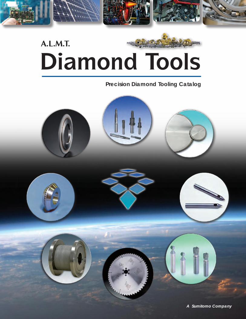
Precision Diamond Tooling Catalog
1
Grinding ToolsP28Easy Wheel
Grinding ToolsP29,30MB Spark
Grinding ToolsP31,32DPG Wheel
Grinding ToolsP13,14RESIACE
Grinding ToolsP15,16Flute Max
Grinding ToolsP17,18CBM Bond Wheel
DresserP41,42Rotary Dresser Option
DresserP36~Rotary Dresser
Cutting ToolsP53UPC Nano Groove
Cutting ToolsP54UPC Nano Endmill
Cutting ToolsP54UPC Nano Profile
Cutting ToolsP61,62PCD Reamer
Cutting ToolsP65PCD Reamer
Cutting ToolsP66PCD Endmill
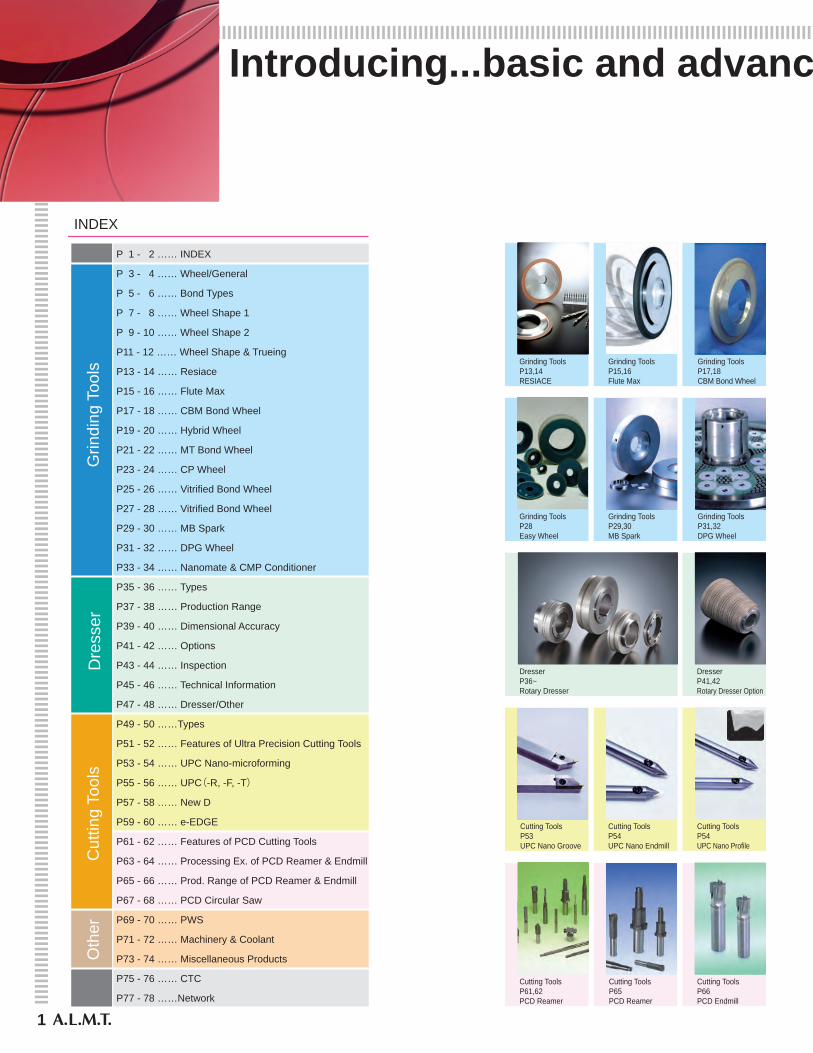
INDEX
P 1 - 2 …… INDEX
P 3 - 4 …… Wheel/General
P 5 - 6 …… Bond Types
P 7 - 8 …… Wheel Shape 1
P 9 - 10 …… Wheel Shape 2
P11 - 12 …… Wheel Shape & Trueing
P13 - 14 …… Resiace
P15 - 16 …… Flute Max
P17 - 18 …… CBM Bond Wheel
P19 - 20 …… Hybrid Wheel
P21 - 22 …… MT Bond Wheel
P23 - 24 …… CP Wheel
P25 - 26 …… Vitrified Bond Wheel
P27 - 28 …… Vitrified Bond Wheel
P29 - 30 …… MB Spark
P31 - 32 …… DPG Wheel
P33 - 34 …… Nanomate & CMP Conditioner
P35 - 36 …… Types
P37 - 38 …… Production Range
P39 - 40 …… Dimensional Accuracy
P41 - 42 …… Options
P43 - 44 …… Inspection
P45 - 46 …… Technical Information
P47 - 48 …… Dresser/Other
P49 - 50 ……Types
P51 - 52 …… Features of Ultra Precision Cutting Tools
P53 - 54 …… UPC Nano-microforming
P55 - 56 …… UPC(-R, -F, -T)
P57 - 58 …… New D
P59 - 60 …… e-EDGE
P61 - 62 …… Features of PCD Cutting Tools
P63 - 64 …… Processing Ex. of PCD Reamer & Endmill
P65 - 66 …… Prod. Range of PCD Reamer & Endmill
P67 - 68 …… PCD Circular Saw
P69 - 70 …… PWS
P71 - 72 …… Machinery & Coolant
P73 - 74 …… Miscellaneous Products
P75 - 76 …… CTC
P77 - 78 ……Network
Grin
ding
Too
lsD
ress
erC
uttin
g To
ols
Oth
erIntroducing...basic and advanc
2
Grinding ToolsP33Nanomate
Grinding ToolsP33Nanomate
Grinding ToolsP34CMP Conditioner
Grinding ToolsP19,20Hybrid Wheel
Grinding ToolsP21,22MT Bond Wheel
Grinding ToolsP23,24CP Wheel
Grinding ToolsP25Vitrified Bond Wheel
Grinding ToolsP26Vitrified Bond Wheel
Grinding ToolsP27Vitrified Bond Wheel
DressersP47One Circle (Straight)
DressersP47One Circle (Cup)
DressersP48Crown Dresser
DressersP48CVD Ace Dresser
DressersP48Disc Dresser
Grinding ToolsP34CMP Conditioner
Cutting ToolsP55UPC-R
Cutting ToolsP56UPC-F
切削ツールP55UPC-R
Cutting ToolsP56UPC-T
Cutting ToolsP57,58New D
Cutting ToolsP59,60e-EDGE
Cutting ToolsP67,68PCD Circular Saw
Misc. ItemsP69,70PWS-R
Misc. ItemsP69,70PWS-E
Misc. ItemsP71CPG Tool Grinder
Misc. ItemsP72Brake Dresser
Misc. ItemsP73 Internal Grinding PinP74 Diamond File
Misc. ItemsP72ODIUP (Coolant)
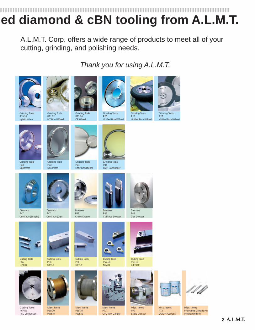
Introducing...basic and advanced diamond & cBN tooling from A.L.M.T.A.L.M.T. Corp. offers a wide range of products to meet all of your cutting, grinding, and polishing needs.
Thank you for using A.L.M.T.
Wheel Figure
Diamond Tools
3
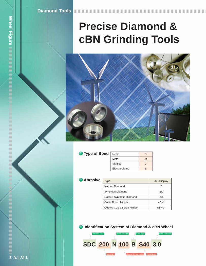
Precise Diamond &cBN Grinding Tools
Resin
Metal
Vitrified
Electro-plated
B
M
V
E
Type of Bond
Type
Natural Diamond
Synthetic Diamond
Coated Synthetic Diamond
Cubic Boron Nitride
Coated Cubic Boron Nitride
JIS Display
D
SD
SDC
cBN*
cBNC*
Abrasive
Identification System of Diamond & cBN WheelAbrasive Type Bond Strength Bond Type
Bond NameAbrasive ConcentrationMesh Size
SDC 200 N 100 B S40 3.0
Bond Thickness
4
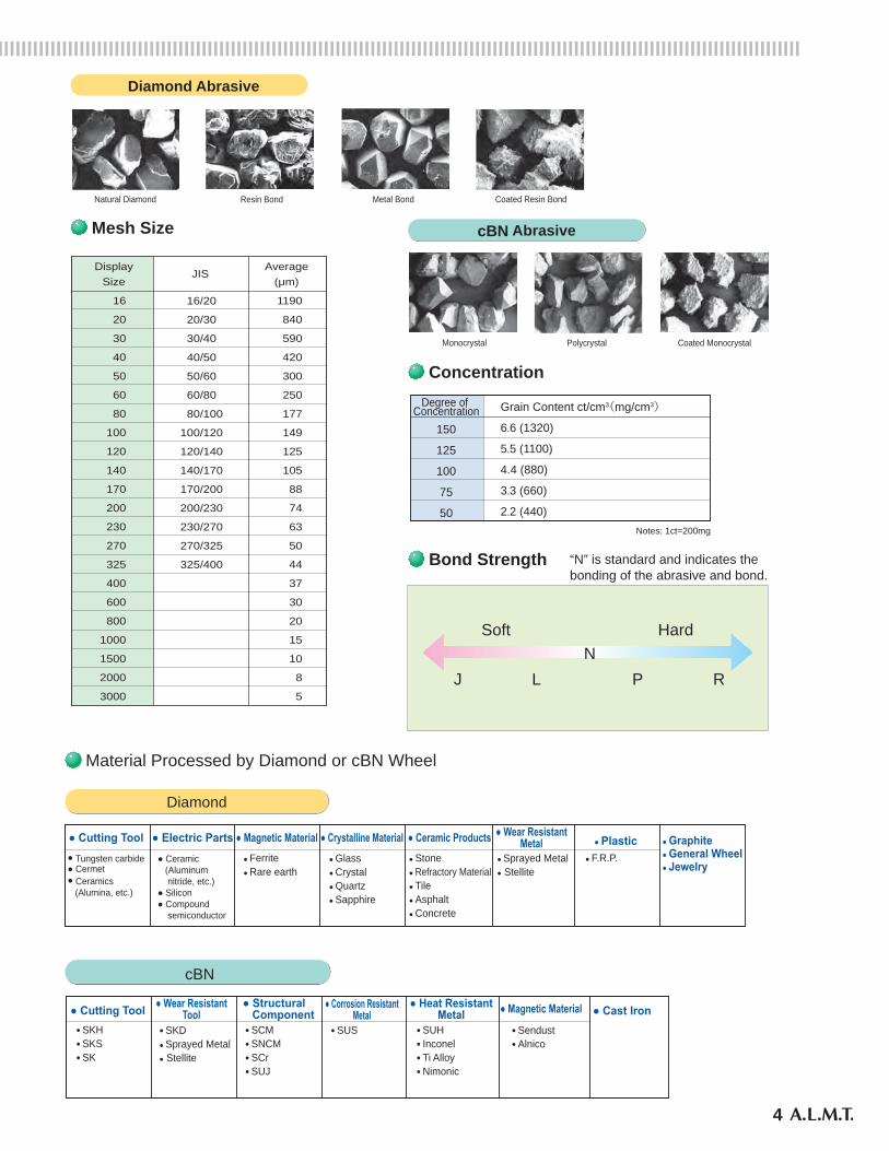
Natural Diamond Resin Bond Metal Bond Coated Resin Bond
Diamond Abrasive
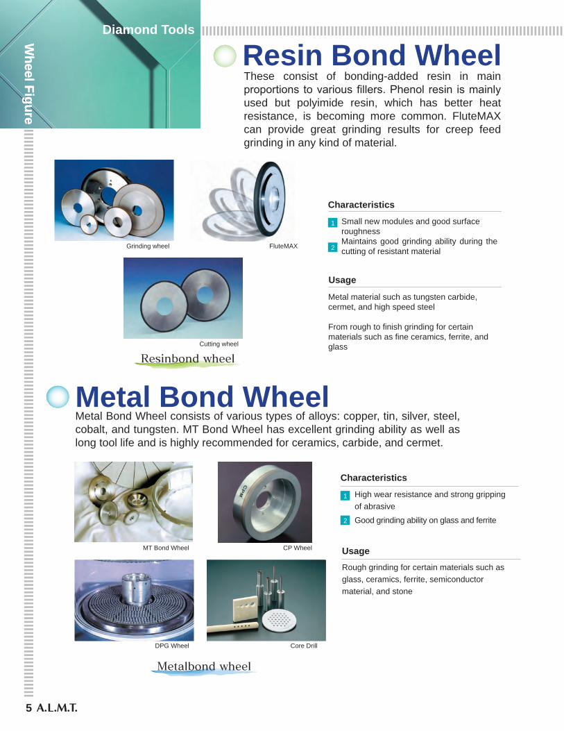
Polycrystal Coated MonocrystalMonocrystal
cBN Abrasive
16
20
30
40
50
60
80
100
120
140
170
200
230
270
325
400
600
800
1000
1500
2000
3000
DisplaySize
1190
840
590
420
300
250
177
149
125
105
88
74
63
50
44
37
30
20
15
10
8
5
Average(μm)
16/20
20/30
30/40
40/50
50/60
60/80
80/100
100/120
120/140
140/170
170/200
200/230
230/270
270/325
325/400
JIS
Mesh Size
Degree of Concentration
150
125
100
75
50
Grain Content ct/cm3(mg/cm3)
6.6 (1320)
5.5 (1100)
4.4 (880)
3.3 (660)
2.2 (440)Notes: 1ct=200mg
Concentration
“N” is standard and indicates thebonding of the abrasive and bond.
P RJ L
Soft HardN
Bond Strength
Material Processed by Diamond or cBN Wheel
Diamond
● Cutting Tool● Tungsten carbide● Cermet● Ceramics (Alumina, etc.)
● Ceramic (Aluminum nitride, etc.)● Silicon● Compound semiconductor
● Ferrite● Rare earth
● Glass● Crystal● Quartz● Sapphire
● Stone● Refractory Material● Tile● Asphalt● Concrete
● Sprayed Metal● Stellite
● F.R.P.
● Electric Parts ● Magnetic Material ● Crystalline Material ● Ceramic Products ● Wear ResistantMetal ● Plastic ● Graphite
● General Wheel● Jewelry
cBN
● SKD● Sprayed Metal● Stellite
● SCM● SNCM● SCr● SUJ
● SUS ● SUH● Inconel● Ti Alloy● Nimonic
● Sendust● Alnico
● Cutting Tool● SKH● SKS● SK
● Wear ResistantTool
● Structural Component
● Corrosion ResistantMetal
● Heat ResistantMetal ● Cast Iron● Magnetic Material
5
Wheel Figure
Diamond Tools
Wheel Figure
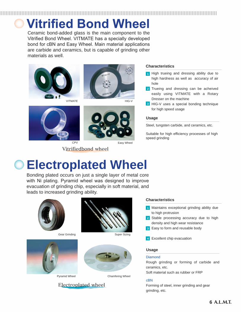
Resin Bond WheelThese consist of bonding-added resin in main proportions to various fillers. Phenol resin is mainly used but polyimide resin, which has better heat resistance, is becoming more common. FluteMAX can provide great grinding results for creep feed grinding in any kind of material.
Grinding wheel FluteMAX
Cutting wheel
Small new modules and good surface roughnessMaintains good grinding ability during the cutting of resistant material
Characteristics
1
2
Usage
Metal material such as tungsten carbide, cermet, and high speed steel
From rough to finish grinding for certain materials such as fine ceramics, ferrite, and glass
Metal Bond WheelMetal Bond Wheel consists of various types of alloys: copper, tin, silver, steel, cobalt, and tungsten. MT Bond Wheel has excellent grinding ability as well as long tool life and is highly recommended for ceramics, carbide, and cermet.
MT Bond Wheel CP Wheel
DPG Wheel Core Drill
UsageRough grinding for certain materials such as glass, ceramics, ferrite, semiconductor material, and stone
Profiling of tungsten carbide
High wear resistance and strong gripping of abrasive
Good grinding ability on glass and ferrite
Characteristics
1
2
UsageRough grinding for certain materials such as glass, ceramics, ferrite, semiconductor material, and stone
Profiling of tungsten carbide
High wear resistance and strong gripping of abrasive
Good grinding ability on glass and ferrite
Characteristics
1
2
6
Vitrified Bond Wheel
VITMATE HIG-V
CPV Easy Wheel
Ceramic bond-added glass is the main component to the Vitrified Bond Wheel. VITMATE has a specially developed bond for cBN and Easy Wheel. Main material applications are carbide and ceramics, but is capable of grinding other materials as well.
Gear Grinding Super Sizing
Pyramid Wheel Chamfering Wheel
High trueing and dressing ability due to high hardness as well as accuracy of air holeTrueing and dressing can be acheived easily using VITMATE with a Rotary Dresser on the machineHIG-V uses a special bonding technique for high speed usage
Characteristics
1
2
3
Usage
Steel, tungsten carbide, and ceramics, etc.
Suitable for high efficiency processes of high speed grinding
Electroplated WheelBonding plated occurs on just a single layer of metal core with Ni plating. Pyramid wheel was designed to improve evacuation of grinding chip, especially in soft material, and leads to increased grinding ability.
Usage
DiamondRough grinding or forming of carbide and ceramics, etc.Soft material such as rubber or FRP
cBNForming of steel, inner grinding and gear grinding, etc.
Maintains exceptional grinding ability due to high protrusionStable processing accuracy due to high density and high wear resistanceEasy to form and reusable body
Excellent chip evacuation
Characteristics
1
2
3
4
7
Wheel Figure
Diamond Tools
Wheel Figure
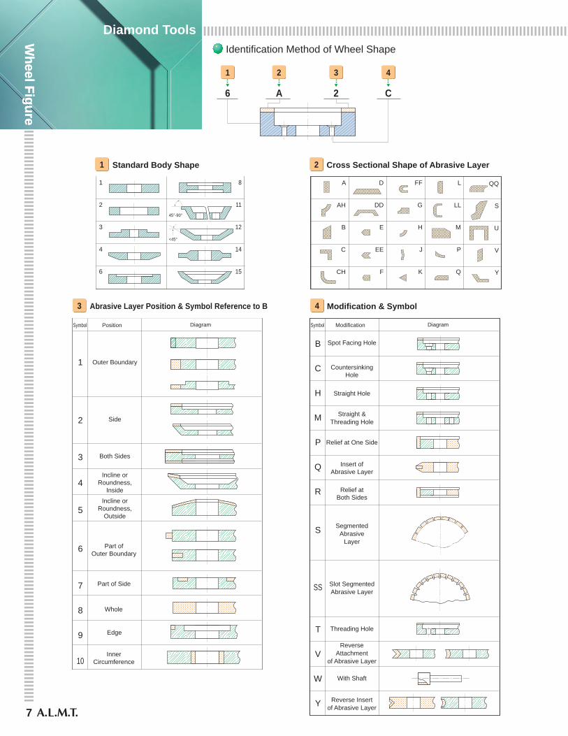
Identification Method of Wheel Shape
1 Standard Body Shape
1
2
3
4
6
8
11
12
14
15
45°-90°
<45°
2 Cross Sectional Shape of Abrasive Layer
A
AH
B
C
CH
D
DD
E
EE
F
FF
G
H
J
K
L
LL
M
P
Q
S
U
V
Y
1
6
2
A
3
2
4
C
3 Abrasive Layer Position & Symbol Reference to Body
1
2
3
4
5
6
7
8
9
10
Symbol Position Diagram
Outer Boundary
Side
Both Sides
Part ofOuter Boundary
Part of Side
Incline orRoundness,
Inside
Incline orRoundness,
Outside
Whole
Edge
InnerCircumference
4 Modification & Symbol
B
C
H
M
P
Q
R
S
SS
T
V
W
Y
Symbol Modification Diagram
Spot Facing Hole
CountersinkingHole
Straight Hole
Straight &Threading Hole
Relief at One Side
SegmentedAbrasive
Layer
Slot SegmentedAbrasive Layer
Threading Hole
Insert ofAbrasive Layer
Relief atBoth Sides
ReverseAttachment
of Abrasive Layer
Reverse Insertof Abrasive Layer
With Shaft
8
D
X
DX
DX
DX
DD1
X 45°
45°
20
D
TT
U
R
R
R
R
TT
VT V
H
H
H
H
H
H
H
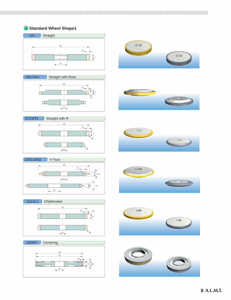
Straight1A1
Straight with Boss3A1/14A1
Straight with R1F1/1FF1
V Face1EE1/1E6Q
Chipbreaker1Q1/1L1
Centering1DD6Y
Standard Wheel Shape1
X
TU
9
Wheel Figure
Diamond Tools
Wheel Figure
D
X
D
X
D
W
X
T
H
DX
TH
T
H
H
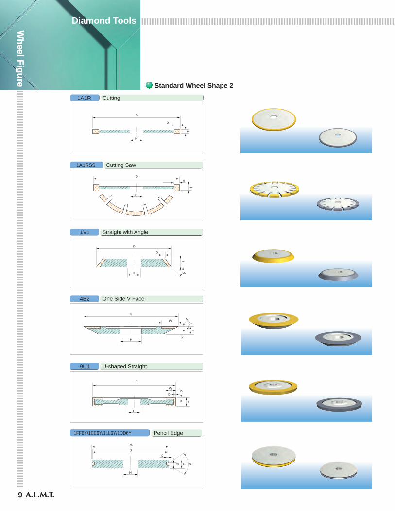
Cutting1A1R
Cutting Saw1A1RSS
Straight with Angle1V1
One Side V Face4B2
U-shaped Straight9U1
Pencil Edge1FF6Y/1EE6Y/1LL6Y/1DD6Y
Standard Wheel Shape 2
DD1
X
H
U
V
TV
D
W
X
X
H
TVT
D
X
D
X
D
W
X
T
H
DX
T
HT
H
H
Cutting1A1R
Cutting Saw1A1RSS
Straight with Angle1V1
One Side V Face4B2
U-shaped Straight9U1
Pencil Edge1FF6Y/1EE6Y/1LL6Y/1DD6Y
Standard Wheel Shape 2
DD1
X
H
U
V
TV
D
W
X
X
H
TVT

10
Standard Wheel Shape 3
Plain Cup6A2
Flair Cup11A2/11B2
Corner Cup6A9/11V9
Wedge-shaped Segment Cup11V2S
Core Drill3A2
Curve Generator3F2
D
W
TH
H
X
D
W
T
X
H
X
D
W
T
X
BL
X
D
W
DW X
DW
X
DWX
DW
X
DW
H
D
W
T
S
X
45°
Standard Wheel Shape 3
Plain Cup6A2
Flair Cup11A2/11B2
Corner Cup6A9/11V9
Wedge-shaped Segment Cup11V2S
Core Drill3A2
Curve Generator3F2
D
W
TH
H
X
D
W
T
X
H
X
D
W
T
X
BL
X
D
W
DW X
DW
X
DWX
DW
X
DW
H
D
W
T
S
X
45°
11
Wheel Figure
Diamond Tools
Wheel Figure Standard Wheel Shape 4
Segment Cup6A2S
L-shaped Flair Cup11C9/11Y9
Dish12A2
Both Side Cup9A3
Chamfering3V2T
Internal with ShankW
Set with Core Drill (3A2)
D
W
L
X
H
D
T
X
L
T
Y
X
D
W
H
D
W
T
X
H
D
WT
X
H
DW
T
X
45゜
X
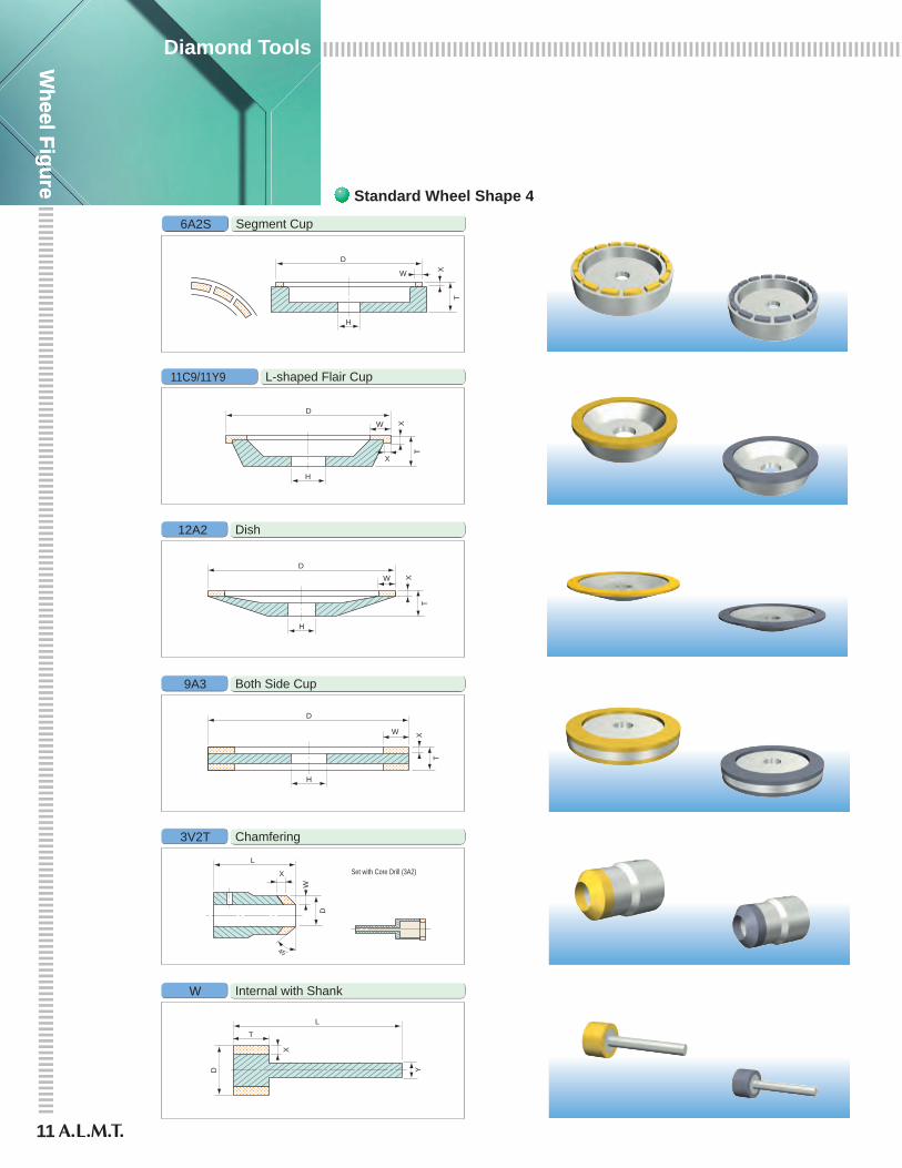
Standard Wheel Shape 4
Segment Cup6A2S
L-shaped Flair Cup11C9/11Y9
Dish12A2
Both Side Cup9A3
Chamfering3V2T
Internal with ShankW
Set with Core Drill (3A2)
D
W
L
X
H
D
T
X
L
T
Y
X
D
W
H
D
W
T
XH
D
W
T
X
H
DW
T
X
45゜
X
12
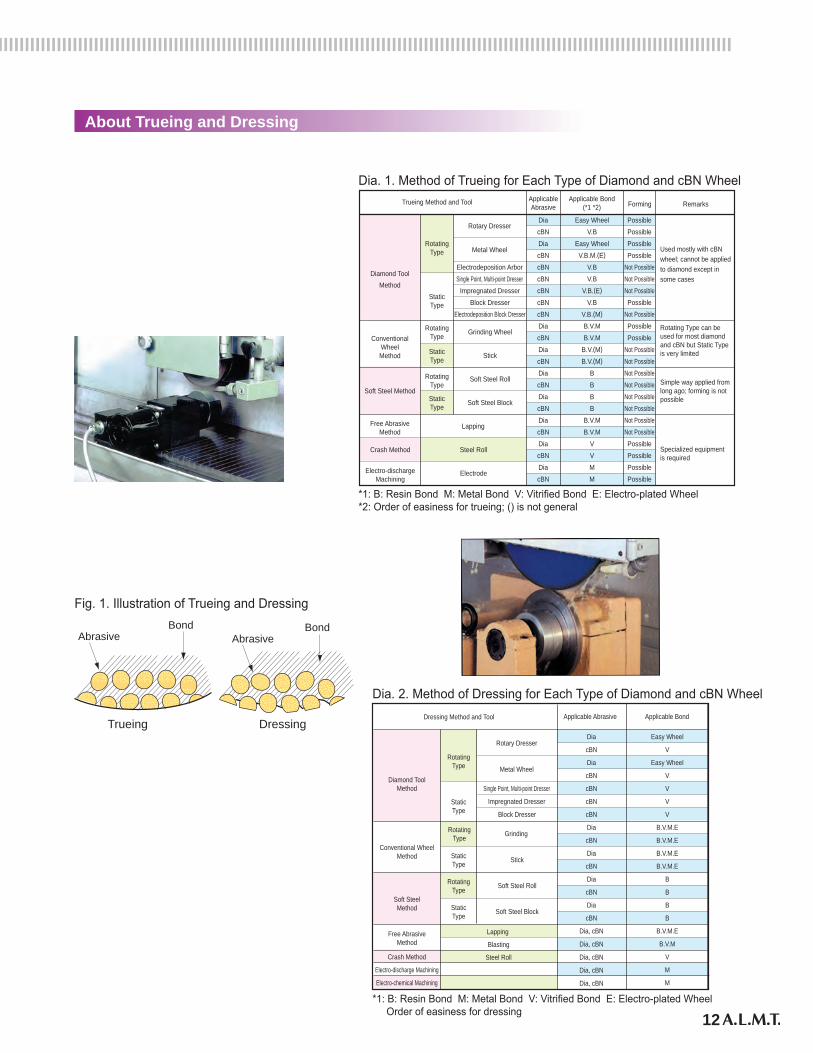
About Trueing and Dressing
ApplicableAbrasive Forming Remarks
Applicable Bond(*1 *2)
Trueing Method and Tool
DiacBNDiacBNcBNElectrodeposition Arbor
Metal Wheel
Rotary Dresser
Single Point, Multi-point DresserDiamond Tool
MethodcBNcBNcBNcBN
Impregnated DresserBlock Dresser
Electrodeposition Block DresserDiacBNDiacBNDiacBNDiacBNDiacBNDiacBNDiacBN
Easy WheelV.B
Easy WheelV.B.M.(E)
V.BV.B
V.B.(E)
V.BV.B.(M)
B.V.MB.V.M
B.V.(M)
B.V.(M)
BBBB
B.V.MB.V.M
VVMM
PossiblePossiblePossiblePossible
Not PossibleNot PossibleNot PossiblePossible
Not PossiblePossiblePossible
Not PossibleNot PossibleNot PossibleNot PossibleNot PossibleNot PossibleNot PossibleNot PossiblePossiblePossiblePossiblePossible
Used mostly with cBNwheel; cannot be appliedto diamond except insome cases
Rotating Type can beused for most diamondand cBN but Static Typeis very limited
Simple way applied fromlong ago; forming is notpossible
Specialized equipmentis required
RotatingType
StaticType
RotatingType
StaticType
RotatingType
StaticType
ConventionalWheelMethod
Soft Steel Method
Grinding Wheel
Stick
Soft Steel Roll
Soft Steel Block
Lapping
Steel Roll
Electrode
Free AbrasiveMethod
Crash Method
Electro-dischargeMachining
Trueing Dressing
AbrasiveBond
AbrasiveBond
Fig. 1. Illustration of Trueing and Dressing
Dia. 1. Method of Trueing for Each Type of Diamond and cBN Wheel
Applicable Abrasive Applicable BondDressing Method and Tool
Dia
cBN
Dia
cBN
cBNSingle Point, Multi-point Dresser
Metal Wheel
Rotary Dresser
Impregnated Dresser
Diamond ToolMethod
cBN
cBN
Dia
cBN
Block Dresser
Grinding RotatingType
Dia
cBN
Dia
cBN
Dia
cBN
Dia, cBN
Dia, cBN
Dia, cBN
Dia, cBN
Dia, cBN
Crash Method
Electro-discharge Machining
Electro-chemical Machining
Easy Wheel
V
Easy Wheel
V
V
V
V
B.V.M.E
B.V.M.E
B.V.M.E
B.V.M.E
B
B
B
B
B.V.M.E
B.V.M
V
M
M
RotatingType
StaticType
StaticType
RotatingType
StaticType
Conventional WheelMethod
Soft SteelMethod
Stick
Soft Steel Roll
Soft Steel Block
Lapping
Blasting
Steel Roll
Free AbrasiveMethod
Dia. 2. Method of Dressing for Each Type of Diamond and cBN Wheel
*1: B: Resin Bond M: Metal Bond V: Vitrified Bond E: Electro-plated Wheel*2: Order of easiness for trueing; () is not general
*1: B: Resin Bond M: Metal Bond V: Vitrified Bond E: Electro-plated Wheel Order of easiness for dressing
Grinding Resin Bond Wheel
13
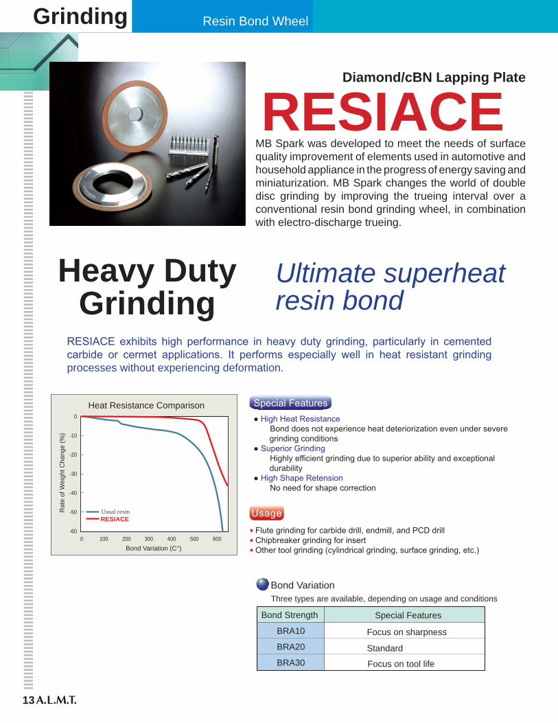
MB Spark was developed to meet the needs of surface quality improvement of elements used in automotive and household appliance in the progress of energy saving and miniaturization. MB Spark changes the world of double disc grinding by improving the trueing interval over a conventional resin bond grinding wheel, in combination with electro-discharge trueing.
RESIACEDiamond/cBN Lapping Plate
Heavy DutyGrinding
Ultimate superheatresin bond
RESIACE exhibits high performance in heavy duty grinding, particularly in cemented carbide or cermet applications. It performs especially well in heat resistant grinding processes without experiencing deformation.
0
-10
-20
-30
-40
-50
-600 100 200 300 400 500 600
Bond Variation (C°)
Rat
e of
Wei
ght C
hang
e (%
)
Heat Resistance Comparison
Usual resinRESIACE
● High Heat Resistance Bond does not experience heat deteriorization even under severe grinding conditions● Superior Grinding Highly efficient grinding due to superior ability and exceptional durability● High Shape Retension No need for shape correction
Special Features
● Flute grinding for carbide drill, endmill, and PCD drill● Chipbreaker grinding for insert● Other tool grinding (cylindrical grinding, surface grinding, etc.)
Usage
Bond Strength
BRA10
BRA20
BRA30
Special Features
Focus on sharpness
Standard
Focus on tool life
Three types are available, depending on usage and conditionsBond Variation
RESIACE
14
Grinding Ability Wear Amount
: SDC140N100BRA30: SDC140-100B (Current resin bond)
60
50
40
30
20
10
00 1000 2000 3000 4000
Cumulative Amount of Material Removed (mm3/mm)
Grin
ding
(N/m
m)
Shift of Grinding Resistance: SDC140N100BRA30 (RESIACE): SDC140-100B (Current resin bond)
80
70
60
50
40
30
20
10
00 1000 2000 3000 4000
The Cumulative Amount of Material Removed (mm3/mm)
Rad
ius
of W
heel
Wea
r Rat
e (μ
m)
Shift of Wheel Wear Amount
Outlined : Normal direction Solid : Tangential direction
(RESIACE)
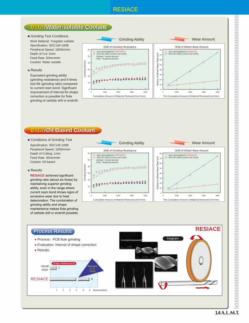
Data /Water-soluble Coolant
Work Material: Tungsten carbideSpecification: SDC140-100BPeripheral Speed: 1600m/minDepth of Cut: 2mmFeed Rate: 50mm/minCoolant: Water soluble
■ Grinding Test Conditions
■ ResultsEquivalent grinding ability (grinding resistance) and 6 times tool life (grinding ratio) compared to current resin bond. Significant improvement of interval for shape correction is possible for flute grinding of carbide drill or endmill.
Data /Oil Based Coolant
Specification: SDC140-100BPeripheral Speed: 1600m/minDepth of Cutting: 1mmFeed Rate: 30mm/minCoolant: Oil based
■ Conditions of Grinding Test
■ ResultsRESIACE achieved significant grinding ratio (about six times) by maintaining superior grinding ability, even in the range where current resin bond shows signs of excessive wear due to heat deterioration. The combination of grinding ability and shape maintenence makes flute grinding of carbide drill or endmill possible.
Grinding Ability Wear Amount
: SDC140N100BRA30: SDC140-100B (Current resin bond)
60
50
40
30
20
10
00 1000 2000 3000 4000
Cumulative Amount of Material Removed (mm3/mm)
Grin
ding
(N/m
m)
Shift of Grinding Resistance: SDC140N100BRA30 (RESIACE): SDC140-100B (Current resin bond)
80
70
60
50
40
30
20
10
00 1000 2000 3000 4000
The Cumulative Amount of Material Removed (mm3/mm)
Rad
ius
of W
heel
Wea
r Rat
e (μ
m)
Shift of Wheel Wear Amount
Outlined : Normal direction Solid : Tangential direction
(RESIACE)
Diagram● Process: PCB flute grinding● Evaluation: Interval of shape correction● Results:
Usualresin
1 2 3 4 5 6 (Exponentiation)
1
6
RESIACE
RESIACE
Shape MaintenanceReached
4 ~6Times
PPPPPPrPrPrPrPrPrProcococococococesesesesesesessssssss RRRRRReReReReReReResususususususultltltltltltltltltltltltsssssssProcess Results

Grinding
15
Resin Bond Wheel
FluteMAX applies super heat resistant resin with a special filler to achieve both superior cutting ability and long tool life. Suitable for grooving applications such as endmills, drills, reamers, and creep feed grinding for various other tools.
Special
Features
● Super heat resistant resin helps to reduce deterioration under very high temperatures.● Excellent cutting ability and shape retention even for heavy load grinding such as creep feed grinding.● High feed rate and long dressing interval compared to conventional items which leads to high efficiency and cost reduction.
● ResultsGrinding force of conventional bond suddenlyincreased and was interrupted due to burn,while the FluteMAX kept low grinding forceand maintained cutting ability.
● Comparison to Conventional Bond for Creep Feed Grinding of Carbide
60
50
40
30
20
10
020 4 6 8 10 12 14 16 18 20 22
×100
Conventional
Cumulative Stock Removal (mm3/mm)
Nor
mal
Dire
ctio
n G
rindi
ng F
orce
(N/m
m)
Wheel SpeedSpeed for Work MaterialD.O.C.
V=1,600m/minF=80mm/mina=0.5mm/pass
cemented carbide
SDC140-100B
Work Material
Wheel Specification
■ Working Conditions
BondWheel
Bond Line Up
Tool Life
Long
Grinding Ability Good
CBM-P
CBM-L
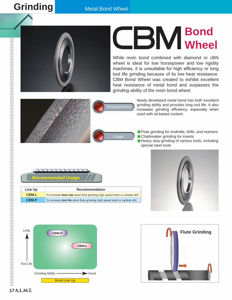
Line Up CBM-L CBM-P
RecommendationTo increase feed rate when flute grinding high speed steel or carbide drill
To increase tool life when flute grinding high speed steel or carbide drill
While resin bond combined with diamond or cBN wheel is ideal for low horsepower and low rigidity machines, it is unsuitable for high efficiency or long tool life grinding because of its low heat resistance. CBM Bond Wheel was created to exhibit excellent heat resistance of metal bond and surpasses the grinding ability of the resin bond wheel.
Grinding
Characteristics
Usage
Newly developed metal bond has both excellent grinding ability and provides long tool life. It also increases grinding efficiency, especially when used with oil-based coolant.
•Flute grinding for endmills, drills, and reamers•Chipbreaker grinding for inserts• Heavy duty grinding of various tools, including special steel tools
Recommended Usage
17
Flute Grinding
Metal Bond Wheel
1251007550
Grin
ding
Res
ista
nce
N
/mm
→
0
20
40
60
80
100
120
140
160
Feed Rate mm/min →
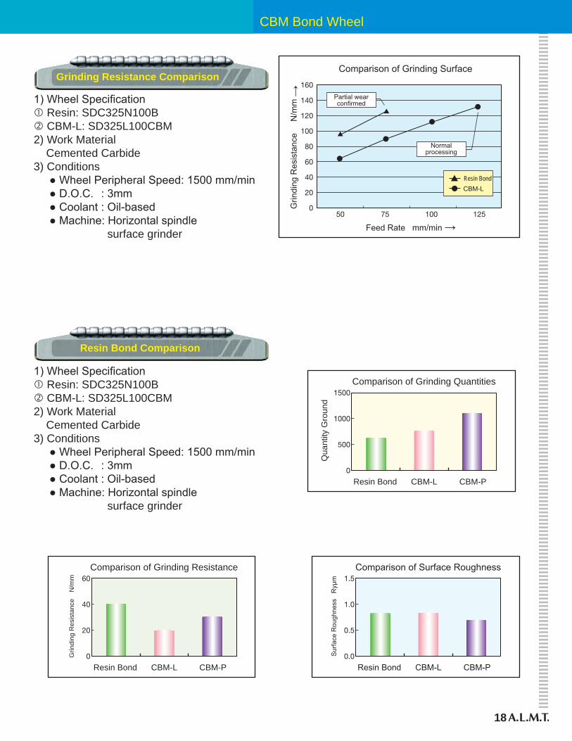
Comparison of Grinding Surface
Partial wearconfirmed
Normalprocessing
▲ Resin Bond● CBM-L
18
Grinding Resistance Comparison
1) Wheel Specification� Resin: SDC325N100B� CBM-L: SD325L100CBM2) Work Material Cemented Carbide3) Conditions ● Wheel Peripheral Speed: 1500 mm/min ● D.O.C. : 3mm ● Coolant : Oil-based ● Machine: Horizontal spindle surface grinder
0
500
1000
1500
Qua
ntity
Gro
und
Resin Bond CBM-L
Comparison of Grinding Quantities
CBM-P
0.0
0.5
1.0
1.5
Sur
face
Rou
ghne
ss
Ryμ
m
Resin Bond CBM-L
Comparison of Surface Roughness
CBM-P0
20
40
60
Grin
ding
Res
ista
nce
N/m
m
Resin Bond CBM-L
Comparison of Grinding Resistance
CBM-P
Resin Bond Comparison
1) Wheel Specification� Resin: SDC325N100B� CBM-L: SD325L100CBM2) Work Material Cemented Carbide3) Conditions ● Wheel Peripheral Speed: 1500 mm/min ● D.O.C. : 3mm ● Coolant : Oil-based ● Machine: Horizontal spindle surface grinder
CBM Bond Wheel
Grinding Metal & Resin Bond Wheel
19
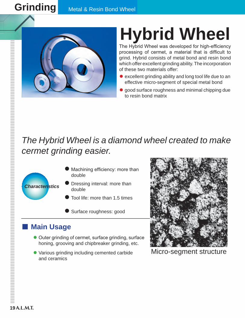
The Hybrid Wheel was developed for high-efficiency processing of cermet, a material that is difficult to grind. Hybrid consists of metal bond and resin bond which offer excellent grinding ability. The incorporation of these two materials offer:
Hybrid Wheel
The Hybrid Wheel is a diamond wheel created to make cermet grinding easier.
• excellent grinding ability and long tool life due to an effective micro-segment of special metal bond
• good surface roughness and minimal chipping due to resin bond matrix
Characteristics
• Machining efficiency: more than double
• Dressing interval: more than double
• Tool life: more than 1.5 times
• Surface roughness: good
Main Usage• Outer grinding of cermet, surface grinding, surface
honing, grooving and chipbreaker grinding, etc.
• Various grinding including cemented carbide and ceramics
Micro-segment structure
Hybrid Wheel
20
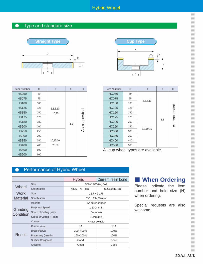
Type and standard size
D
H
X
T
D
H
X
T
W
HC050HC075HC100HC125HC150HC175HC200HC250HC300HC350HC400HC500
50
75
100
125
150
175
200
250
300
350
400
500
Item Number D T X H
3,5,8,10
5,8,10,15
3,5
HS050HS075HS100HS125HS150HS175HS180HS200HS250HS300HS350HS400HS500HS600
50
75
100
125
150
175
180
200
250
300
350
400
500
600
Item Number D T X H
3,5,8,10,
15,20
10,15,20,
25,30
3,5
As
requ
este
d
As
requ
este
d
All cup wheel types are available.
● Performance of Hybrid Wheel
350×12W×6×, 6A2
12.7 × 3.175
TIC-TIN Cermet
TA outer grinder
1,600m/min
3mm/min
40mm/min
Water soluble
9A
300~400%
150~200%
Good
Good
10A
100%
100%
Good
Good
#325-75-HB SDC325R75BWheelWork
Material
GrindingCondition
Result
Hybrid Current resin bondSize
Specification
Size
Specification
Machine
Peripheral Speed
Speed of Cutting (side)
Speed of Cutting (R part)
Coolant
Current Value
Dress Interval
Processing Quantity
Surface Roughness
Chipping
When OrderingPlease indicate the item number and hole size (H) when ordering.
Special requests are also welcome.
Straight Type Cup Type
Grinding Metal Bond Wheel
21
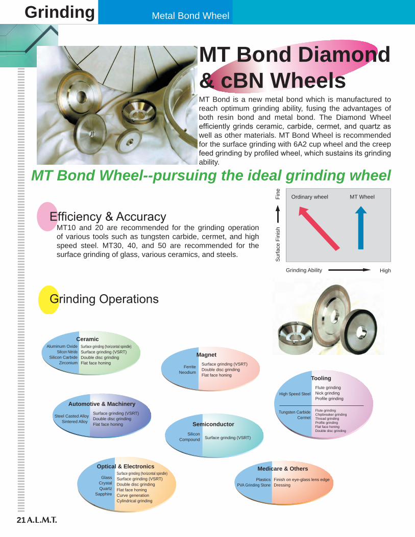
MT Bond Diamond& cBN WheelsMT Bond is a new metal bond which is manufactured to reach optimum grinding ability, fusing the advantages of both resin bond and metal bond. The Diamond Wheel efficiently grinds ceramic, carbide, cermet, and quartz as well as other materials. MT Bond Wheel is recommended for the surface grinding with 6A2 cup wheel and the creep feed grinding by profiled wheel, which sustains its grinding ability.
MT Bond Wheel--pursuing the ideal grinding wheel
Sur
face
Fin
ish
Fine
Grinding Ability High
MT WheelOrdinary wheel
Tungsten CarbideCermet
ToolingFlute grindingNick grindingProfile grinding
Flute grindingChipbreaker grindingThread grindingProfile grindingFlat face honingDouble disc grinding
GlassCrystalQuartz
Sapphire
Optical & Electronics
Aluminum OxideSilicon Nitride
Silicon CarbideZirconium
CeramicSurface grinding (horizontal spindle)Surface grinding (VSRT)Double disc grindingFlat face honing
Steel Casted AlloySintered Alloy
Automotive & Machinery
PlasticsPVA Grinding Stone
Medicare & Others
Finish on eye-glass lens edgeDressing
SiliconCompound
Semiconductor
Surface grinding (VSRT)
FerriteNeodium
Magnet
Surface grinding (VSRT)Double disc grindingFlat face honing
Surface grinding (horizontal spindle)Surface grinding (VSRT)Double disc grindingFlat face honingCurve generationCylindrical grinding
Surface grinding (VSRT)Double disc grindingFlat face honing
High Speed Steel
Efficiency & Accuracy
Grinding Operations
MT10 and 20 are recommended for the grinding operation of various tools such as tungsten carbide, cermet, and high speed steel. MT30, 40, and 50 are recommended for the surface grinding of glass, various ceramics, and steels.
MT Bond Wheel
22
Straight Style Cup Style
Type
1A1
3A1
14A1
D
50
75
100
150
200
250
2~30
3~30
3,5,7
300
400
T X H
As specified
Grit Size
60
3,000
~
25
125
~
Concentration
6A2
11A2
12A2
11B2
6A9
6A2S
D
50
75
100
125
150
175
200
250
300
350
400
500
600
W X
3,5,10
H
60
3,000
25
125
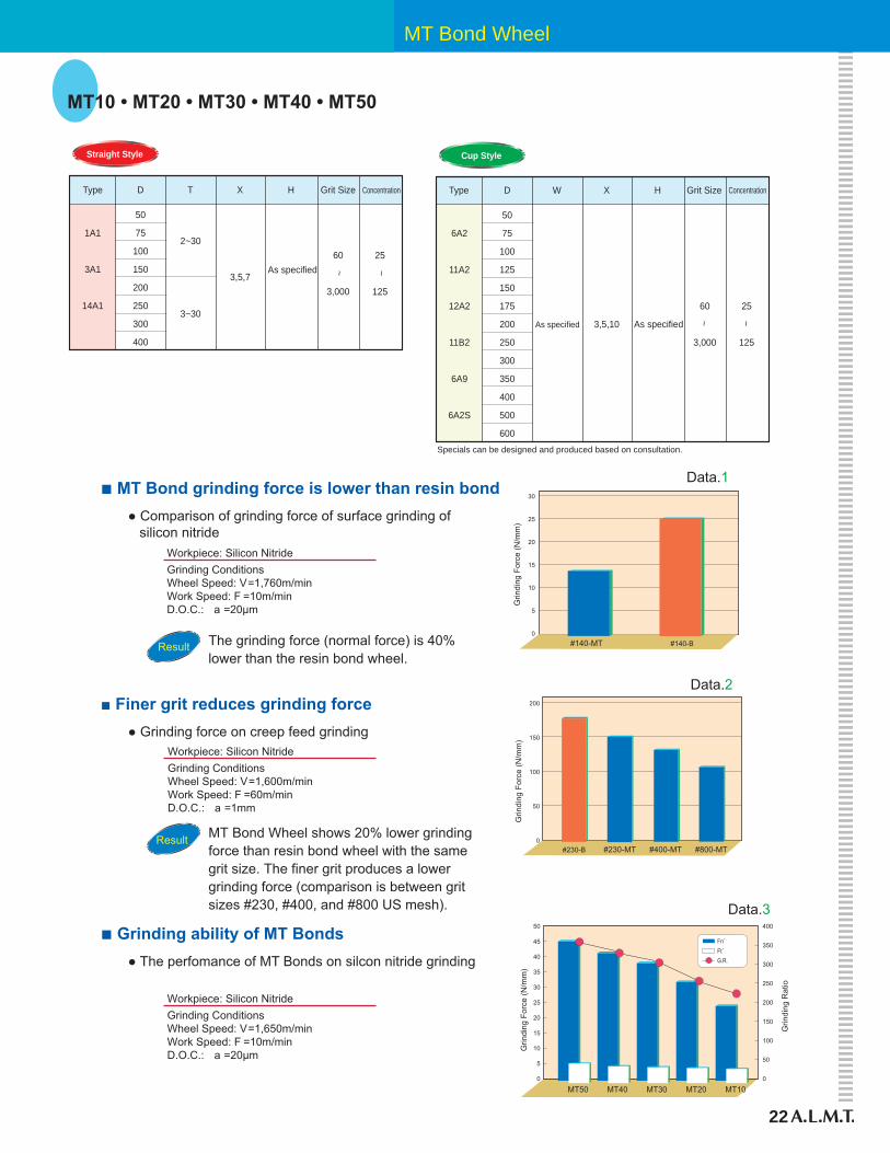
MT10 • MT20 • MT30 • MT40 • MT50
Specials can be designed and produced based on consultation.
Type Grit Size Concentration
As specified As specified ~ ~
● Comparison of grinding force of surface grinding of silicon nitride
Data.1
0
5
10
15
20
#140-MT #140-B
25
30
Grin
ding
For
ce (N
/mm
)
Workpiece: Silicon NitrideGrinding Conditions Wheel Speed: V=1,760m/minWork Speed: F =10m/minD.O.C.: a =20μm
Result The grinding force (normal force) is 40%lower than the resin bond wheel.
Data.2
0
50
100
150
200
#230-B #230-MT #400-MT #800-MT
Grin
ding
For
ce (N
/mm
)
■ MT Bond grinding force is lower than resin bond
● Grinding force on creep feed grinding
MT Bond Wheel shows 20% lower grindingforce than resin bond wheel with the samegrit size. The finer grit produces a lowergrinding force (comparison is between gritsizes #230, #400, and #800 US mesh).
■ Finer grit reduces grinding force
● The perfomance of MT Bonds on silcon nitride grinding
■ Grinding ability of MT Bonds
Workpiece: Silicon Nitride Grinding Conditions Wheel Speed: V=1,600m/minWork Speed: F =60m/minD.O.C.: a =1mm
Workpiece: Silicon Nitride Grinding Conditions Wheel Speed: V=1,650m/minWork Speed: F =10m/minD.O.C.: a =20μm
Data.3
0
Grin
ding
For
ce (N
/mm
)
Grin
ding
Rat
io
5
10
15
20
25
30
35
40
45
50 400
350
300
250
200
150
100
50
0
MT50 MT40 MT30 MT20 MT10
Fn´Ft´G.R.
Result
Grinding Vit & Metal Bond Wheel
23
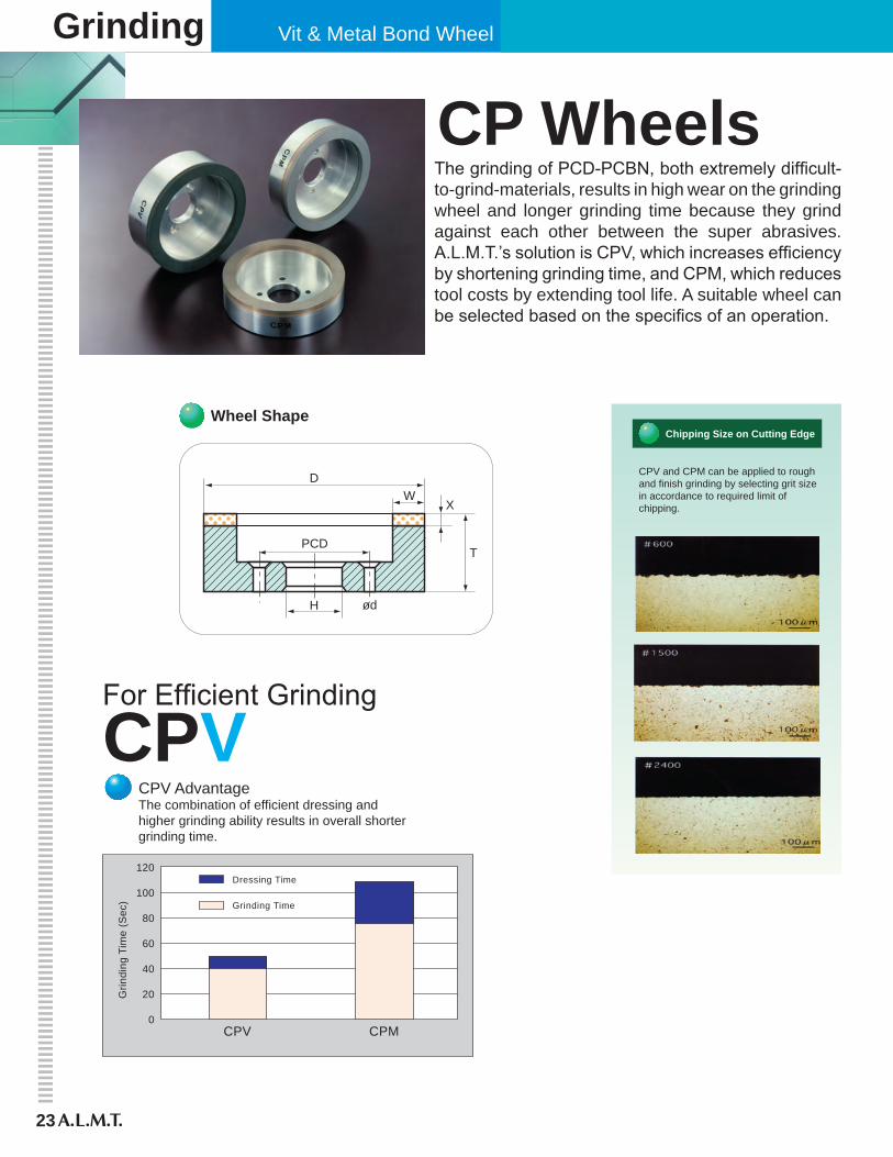
CPV AdvantageThe combination of efficient dressing andhigher grinding ability results in overall shorter grinding time.
CPV and CPM can be applied to roughand finish grinding by selecting grit sizein accordance to required limit ofchipping.
Chipping Size on Cutting Edge
0CPV CPM
20
40
60
80
100
120
Grin
ding
Tim
e (S
ec)
Dressing Time
Grinding Time
CPV AdvantageThe combination of efficient dressing andhigher grinding ability results in overall shorter grinding time.
CPV and CPM can be applied to roughand finish grinding by selecting grit sizein accordance to required limit ofchipping.
Chipping Size on Cutting Edge
CP WheelsThe grinding of PCD-PCBN, both extremely difficult-to-grind-materials, results in high wear on the grinding wheel and longer grinding time because they grind against each other between the super abrasives. A.L.M.T.’s solution is CPV, which increases efficiency by shortening grinding time, and CPM, which reduces tool costs by extending tool life. A suitable wheel can be selected based on the specifics of an operation.
Wheel Shape
DW
X
T
ød
PCD
H
CPVFor Efficient Grinding
CP Wheel
24
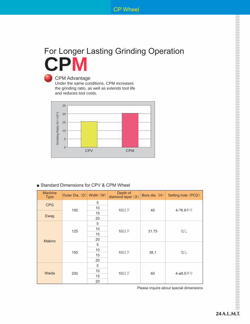
CPM AdvantageUnder the same conditions, CPM increasesthe grinding ratio, as well as extends tool lifeand reduces tool costs.
0
5
10
15
20
25
CPV CPM
Grin
ding
Rat
io G
r(×1
0-3)
CPMFor Longer Lasting Grinding Operation
Width (W)
5101520510152051015205101520
Depth ofdiamond layer (X)Bore dia. (H) Setting hole (PCD)Outer Dia. (D)
150
125
150
200
10以下
10以下
10以下
10以下
40
31.75
38.1
60
4-?6.8キリ
なし
なし
4-ø8.5キリ
MachineType
CPG
Makino
Waida
Ewag
■ Standard Dimensions for CPV & CPM Wheel
Please inquire about special dimensions

Grinding Vitrified Bond Wheel
25
VITMATEFeatures
Applications
High accuracy and efficiency grinding with VX bond for longer wheel life and exceptional grindability
Multiple combinations of porosity and bond grades for a wide range of applications
Controllable dressing ability for required surface roughness and grinding speed
High holding power with cBN grain
Industries: Automotive, bearing, household appliances, tools, machinery, gears, mold & dieWork piece: Cam, crank shaft, injection needle, rocker arm, compressor, bearing, ball screw, motor
Running ConditionsO.D.ThicknessWidthSpec.
ø3~750mm3~300mm2~15mmcBN(#60~#2000)
2 times dressing interval for compressor componentData1.
Piece & Material: Compressor component, SCM415(HRC62)Stock Removal: O.D. = 0.28 End Face = 0.15mm
Roughness
Grinding time
Dressing interval
Wheel life
5.0μmRmax
40sec
400 pcs.
70,000 pcs.
3.2μmRmax
30sec
800 pcs.
140,000 pcs.
56% improved
25% improved
Operating rate increased
Wheel life extended
O.D.Grinding
End Face Grinding ■ Application Example 1. Machine : Angular grinder 2. Wheel :350D-22U BN120N175VX5 3. Dresser :Diamond rotary dresser SD40M 4. Conditions : Peripheral speed = 80m/s Work rotation = 320 rpm Stock allowance = O.D. 0.28mm End Face 0.15mm Coolant emulsion = 5%
■ ResultsVITMATEConventional Efficiency
VITMATE & UNIMATE
26
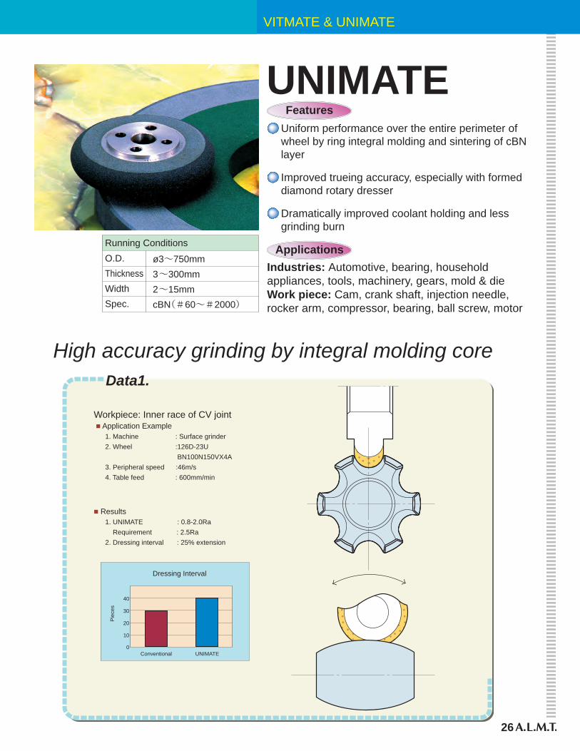
UNIMATEFeatures
Applications
Uniform performance over the entire perimeter of wheel by ring integral molding and sintering of cBN layer
Dramatically improved coolant holding and less grinding burn
Improved trueing accuracy, especially with formed diamond rotary dresser
Industries: Automotive, bearing, household appliances, tools, machinery, gears, mold & dieWork piece: Cam, crank shaft, injection needle, rocker arm, compressor, bearing, ball screw, motor
Running ConditionsO.D.ThicknessWidthSpec.
ø3~750mm3~300mm2~15mmcBN(#60~#2000)
High accuracy grinding by integral molding coreData1.
0
10
20
30
40
Conventional UNIMATE
Dressing Interval
Pie
ces
■ Application Example 1. Machine : Surface grinder 2. Wheel :126D-23U BN100N150VX4A 3. Peripheral speed :46m/s 4. Table feed : 600mm/min
■ Results 1. UNIMATE : 0.8-2.0Ra Requirement : 2.5Ra 2. Dressing interval : 25% extension
Workpiece: Inner race of CV joint
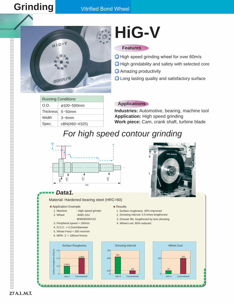
Data1.Material: Hardened bearing steel (HRC=60)
■ Application Example 1. Machine : High speed grinder 2. Wheel :400D-10U BN60M200VX2 3. Peripheral speed = 160m/s 4. D.O.C. = 0.2mm/diameter 5. Wheel Feed = 300 mm/min 6. MRR: Z’ = 180mm3/mm/s
■ Results 1. Surface roughness: 40% improved 2. Dressing interval: 5.5 times lengthened 3. Dresser life: lengthened by less dressing 4. Wheel cost: 80% reduced
0
1.0
1.4
1.0μm
1.4μm
1.8
Conventional
Surface Roughness
Sur
face
Rou
ghne
ss (R
zμm
)
0
500550
100
750
100
Dressing Interval
0
100
20
100
Wheel Cost
HiG-V ConventionalHiG-V ConventionalHiG-V
Grinding Vitrified Bond Wheel
27
HiG-VFeatures
High speed grinding wheel for over 60m/s
Amazing productivityLong lasting quality and satisfactory surface
High grindability and safety with selected core
ApplicationsIndustries: Automotive, bearing, machine toolApplication: High speed grindingWork piece: Cam, crank shaft, turbine blade
Running Conditions
ø100~500mm5~50mm3~6mmcBN(#60~#325)
O.D.ThicknessWidthSpec.
200
ø60 ø45
ø37
ø35
For high speed contour grinding
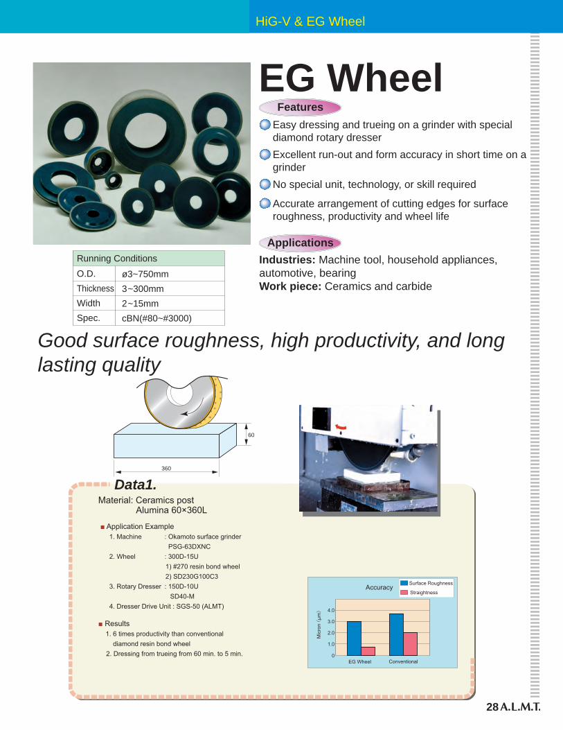
HiG-V & EG Wheel
28
360
60
Data1.
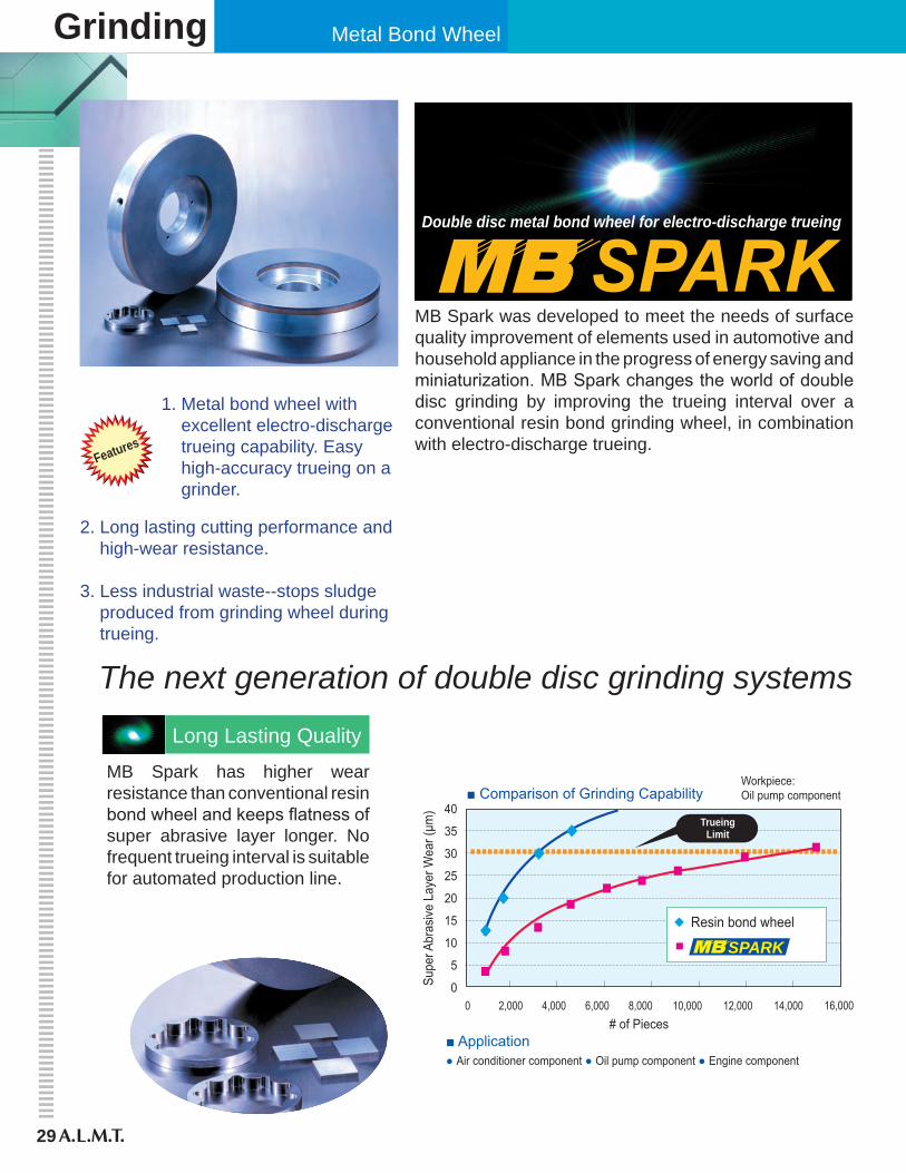
0
1.0
2.0
3.0
4.0
EG Wheel Conventional
Accuracy
Mic
ron (
μm)
Surface Roughness
Straightness
Material: Ceramics post Alumina 60×360L
■ Application Example 1. Machine : Okamoto surface grinder PSG-63DXNC 2. Wheel : 300D-15U 1) #270 resin bond wheel 2) SD230G100C3 3. Rotary Dresser : 150D-10U SD40-M 4. Dresser Drive Unit : SGS-50 (ALMT)
■ Results 1. 6 times productivity than conventional diamond resin bond wheel 2. Dressing from trueing from 60 min. to 5 min.
EG WheelFeatures
Applications
Easy dressing and trueing on a grinder with special diamond rotary dresser
No special unit, technology, or skill required
Excellent run-out and form accuracy in short time on a grinder
Industries: Machine tool, household appliances, automotive, bearingWork piece: Ceramics and carbide
Accurate arrangement of cutting edges for surface roughness, productivity and wheel life
Good surface roughness, high productivity, and long lasting quality
Running Conditions
ø3~750mm3~300mm2~15mmcBN(#80~#3000)
O.D.ThicknessWidthSpec.
Grinding Metal Bond Wheel
29
Double disc metal bond wheel for electro-discharge trueing
MB Spark was developed to meet the needs of surface quality improvement of elements used in automotive and household appliance in the progress of energy saving and miniaturization. MB Spark changes the world of double disc grinding by improving the trueing interval over a conventional resin bond grinding wheel, in combination with electro-discharge trueing.
Features
1. Metal bond wheel with excellent electro-discharge trueing capability. Easy high-accuracy trueing on a grinder.
The next generation of double disc grinding systems
2. Long lasting cutting performance and high-wear resistance.
3. Less industrial waste--stops sludge produced from grinding wheel during trueing.
Long Lasting Quality
MB Spark has higher wear resistance than conventional resin bond wheel and keeps flatness of super abrasive layer longer. No frequent trueing interval is suitable for automated production line.
■ Application● Air conditioner component ● Oil pump component ● Engine component
■ Comparison of Grinding Capability
00 2,000 4,000 6,000 8,000 10,000 12,000 14,000 16,000
5
10
15
20
25
30
35
40
Workpiece:Oil pump component
# of Pieces
Supe
r Abr
asive
Lay
er W
ear (
μm)
Resin bond wheel
TrueingLimit
SPARK
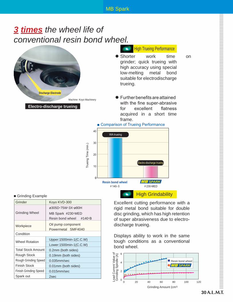
MB Spark
30
3 times the wheel life of conventional resin bond wheel.
Electro-discharge trueing
Machine: Koyo Machinery
Discharge Electrode
High Trueing Performance
• Shorter work time on grinder; quick trueing with high accuracy using special low-melting metal bond suitable for electrodischarge trueing.
• Further benefits are attained with the fine super-abrasive for excellent flatness acquired in a short time frame.
■ Comparison of Trueing Performance
True
ing
Tim
e (m
in.)
Resin bond wheel#140-B #230-MED
WA trueing
Electro-discharge trueing10
20
30
40
SPARK
Grinder
Grinding Wheel
Workpiece
Condition
Wheel Rotation
Total Stock Amount Rough StockRough Grinding SpeedFinish StockFinish Grinding SpeedSpark out
■ Grinding ExampleKoyo KVD-300
ø305D-75W-3X-ø80H
MB Spark #230-MEDResin bond wheel #140-B
Oil pump componentPowermetal SMF4040
Upper:1500min-1(C.C.W)Lower:1500min-1(C.C.W)0.2mm (both sides)0.19mm (both sides)0.035mm/sec0.01mm (both sides)0.015mm/sec2sec
High Grindability
Excellent cutting performance with a rigid metal bond suitable for double disc grinding, which has high retention of super abrasiveness due to electro-discharge trueing.
Displays ability to work in the same tough conditions as a conventional bond wheel.
Grinding Amount (cm3)
Load
Cur
rent
Val
ue o
fG
rindi
ng S
pind
le (A
)
00
2
4
6
20 40 60 80 100 120
Resin bond wheel
SPARK
Grinding Vit & Metal Bond Wheel
31
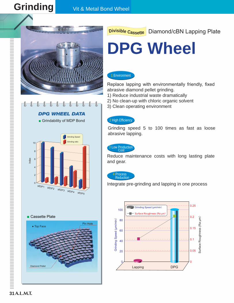
■ Grindability of MDP Bond
0
2
4
6
8
10
MDP1 MDP2 MDP3 MDP4 MDP5
Inde
x
Grinding Speed
Grinding ratio
■ Cassette Plate
● Top Face
Diamond Pellet
Pin Hole
DPG WheelDivisible Cassette Diamond/cBN Lapping Plate
4 Process Reduction
3 Low Production Cost
2 High Efficiency
1 Environment
Replace lapping with environmentally friendly, fixed abrasive diamond pellet grinding.1) Reduce industrial waste dramatically2) No clean-up with chloric organic solvent3) Clean operating environment
4 Process Reduction
3 Low Production Cost
2 High Efficiency
1 Environment
Grinding speed 5 to 100 times as fast as loose abrasive lapping.
4 Process Reduction
3 Low Production Cost
2 High Efficiency
1 Environment
Reduce maintenance costs with long lasting plate and gear.
4 Process Reduction
3 Low Production Cost
2 High Efficiency
1 Environment
Integrate pre-grinding and lapping in one process
Grin
ding
Spe
ed (μ
m/m
in)
Sur
face
Rou
ghne
ss (R
a μm)
Lapping DPG0
0.05
0.1
0.15
0.2
0.25
0
20
40
60
80
100Grinding Speed (μm/min)
Surface Roughness (Ra μm)

DPG Wheel
32
Workpiece: Alumina ø80-5T-ø70HWheel Specs: 9B SD400-MDP4 ● Conditions 1)Top Plate: 7min-1
2) Bottom Plate: 20min-1
3) Sun Gear: 9min-1
4) Internal Gear: 7min-1
5) Grinding Pressure: 15KPa 6) Coolant: ODIAP (2%)
Metal bond wheelMDP Series (rough grinding)
Example application
0
2
4
6
8
10
12
14
16
Lapping DPG
Grin
ding
Spe
ed (μ
m/m
in)
15 times
0
0.5
1
1.5
2
2.5
Lapping DPG
TTV(
μm) Equal
Workpiece: Tool Steel ø20-3TWheel Specs: 9B SD2000-VDP3 ● Conditions 1)Top Plate: 50min-1
2) Bottom Plate: 50min-1
3) Sun Gear: 10min-1
4) Interal Gear: 0min-1
5) Grinding Pressure: 200KPa 6) Coolant: ODIAP (2%)
Vitrified Bond WheelVDP Series (finish grinding)
Superior Fine Grain
0
10
20
30
40
50
60
70
Lapping DPG
Grin
ding
Spe
ed(μm
/min
)
60 times
0
0.1
0.2
0.3
0.4
0.5
0.6
Lapping DPG
Flat
ness
(μm
) Equal
■ No detaching base plate ■ Divisible cassette fixed on base plate ■ Short dressing time (9B = 20 minutes, less than 2 hours for 16B)
■ Divisible cassette designed for pellet layout ■ Seams never interfere with the density of pellet distribution
■ Coolant pool on clamp face
� Easy change of plate
� Pellet pattern keeps high grinding accuracy
� Free layout of coolant hole for top plate
Size Max. Dia. Min. Dia.
299
389
380
650
637
1058
950
1022
1127
1260
1355
1592
1864
117
213
148
384
218
360
274
346
270
294
458
554
660
4B
5B
6B
6B/9B
9B
12B
13B
15B
16B
18B
20B
24B
28B
*Special sizes also available
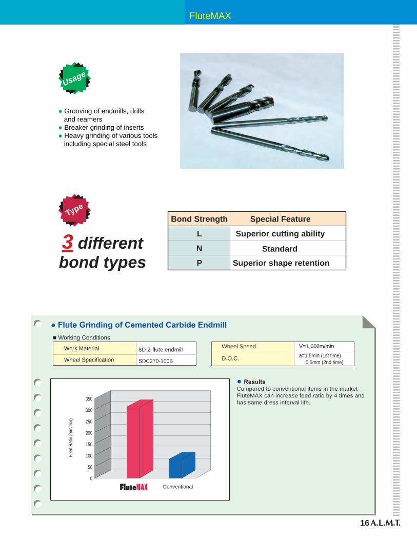
FluteMAX
16
Usage
● ResultsCompared to conventional items in the marketFluteMAX can increase feed ratio by 4 times andhas same dress interval life.
● Flute Grinding of Cemented Carbide Endmill
Wheel Speed
D.O.C.
V=1,600m/min
a=1.5mm (1st time) 0.5mm (2nd time)
8D 2-flute endmill
SDC270-100B
Work Material
Wheel Specification
■ Working Conditions
Conventional
Feed
Rat
io (m
m/m
in)
0
50
100
150
200
250
300
350
Type
● Grooving of endmills, drills and reamers● Breaker grinding of inserts● Heavy grinding of various tools including special steel tools
Bond Strength
L
N
P
Special Feature
Superior cutting ability
StandardSuperior shape retention
3 differentbond types
Grinding
33
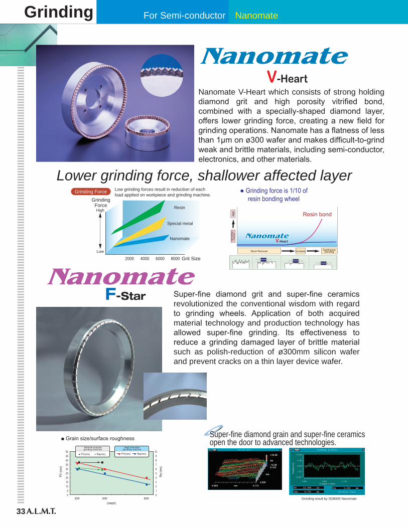
For Semi-conductor Nanomate
Nanomate V-Heart which consists of strong holding diamond grit and high porosity vitrified bond, combined with a specially-shaped diamond layer, offers lower grinding force, creating a new field for grinding operations. Nanomate has a flatness of less than 1µm on ø300 wafer and makes difficult-to-grind weak and brittle materials, including semi-conductor, electronics, and other materials.
Lower grinding force, shallower affected layer
ナノメイト特殊メタル
レジン
GrindingForce
Grit Size
High
Low
2000 4000 6000 8000
Resin
Special metal
Nanomate
Grinding Force Low grinding forces result in reduction of eachload applied on workpiece and grinding machine.
● Grinding force is 1/10 ofresin bonding wheel
V-Heart
Stock Removal Increase ContinuousGrinding
Grindin
gF
orc
eH
igh Resin bond
V-Heart
F-Star Super-fine diamond grit and super-fine ceramics revolutionized the conventional wisdom with regard to grinding wheels. Application of both acquired material technology and production technology has allowed super-fine grinding. Its effectiveness to reduce a grinding damaged layer of brittle material such as polish-reduction of ø300mm silicon wafer and prevent cracks on a thin layer device wafer.
Grinding result by SD8000 Nanomate
Super-fine diamond grain and super-fine ceramicsopen the door to advanced technologies.■ Grain size/surface roughness
03000
PV (n
m)
(mesh)
Ra (n
m)
5000 8000
5101520253035404550
0123456789
10General purposegrinding machine
High precisiongrinding machine
● PV(nm) ● Ra(nm) ■ Ra(nm)■ PV(nm)
34
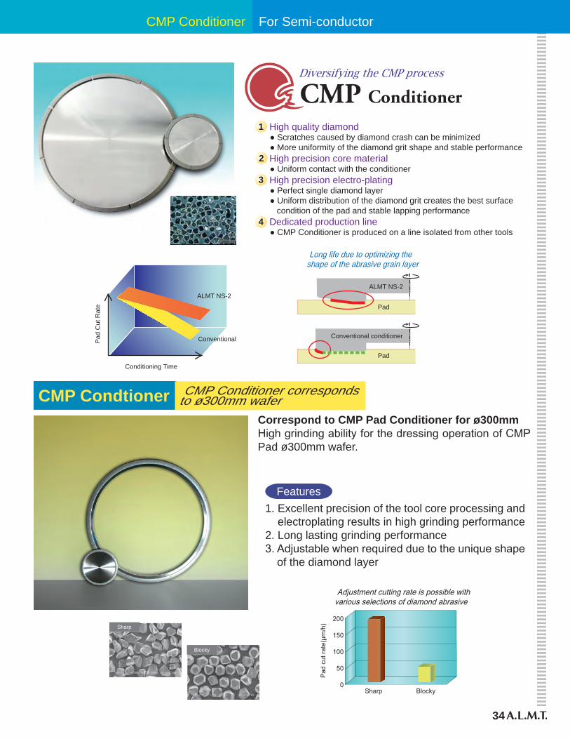
For Semi-conductorCMP Conditioner
Diversifying the CMP process
High quality diamond ● Scratches caused by diamond crash can be minimized ● More uniformity of the diamond grit shape and stable performance High precision core material ● Uniform contact with the conditioner High precision electro-plating ● Perfect single diamond layer ● Uniform distribution of the diamond grit creates the best surface condition of the pad and stable lapping performance Dedicated production line ● CMP Conditioner is produced on a line isolated from other tools
1
2
3
4
Pad
Pad
ALMT NS-2
Conventional conditioner
Long life due to optimizing theshape of the abrasive grain layer
Pad
Cut
Rat
e
Conditioning Time
Conventional
ALMT NS-2
Sharp
Pad
cut
rate
(μm
/h)
Blocky
Adjustment cutting rate is possible withvarious selections of diamond abrasive
0
50
100
150
200
Blocky
Sharp
Correspond to CMP Pad Conditioner for ø300mmHigh grinding ability for the dressing operation of CMP Pad ø300mm wafer.
Features1. Excellent precision of the tool core processing and
electroplating results in high grinding performance2. Long lasting grinding performance3. Adjustable when required due to the unique shape
of the diamond layer
CMP Conditioner correspondsto ø300mm waferCMP Condtioner
35
Rotary D
ressers
Diamond Tools
Rotary DressersSuper-fine diamond grit and super-fine ceramics revolutionized the conventional wisdom with regard to grinding wheels. Application of both acquired material technology and production technology has allowed super-fine grinding. Its effectiveness to reduce a grinding damaged layer of brittle material such as polish-reduction of ø300mm silicon wafer and prevent cracks on a thin layer device wafer.
36
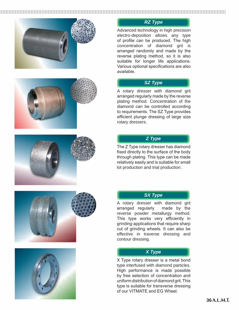
RZ Type
SZ Type
Z Type
SX Type
X Type
Advanced technology in high precision electro-deposition allows any type of profile can be produced. The high concentration of diamond grit is arranged randomly and made by the reverse plating method, so it is also suitable for longer life applications. Various optional specifications are also available.
RZ Type
SZ Type
Z Type
SX Type
X Type
A rotary dresser with diamond grit arranged regularly made by the reverse plating method. Concentration of the diamond can be controlled according to requirements. The SZ Type provides efficient plunge dressing of large size rotary dressers.
RZ Type
SZ Type
Z Type
SX Type
X Type
The Z Type rotary dresser has diamond fixed directly to the surface of the body through plating. This type can be made relatively easily and is suitable for small lot production and trial production.
RZ Type
SZ Type
Z Type
SX Type
X TypeA rotary dresser with diamond grit arranged regularly made by the reverse powder metallurgy method. This type works very efficiently in grinding applications that require sharp cut of grinding wheels. It can also be effective in traverse dressing and contour dressing.
RZ Type
SZ Type
Z Type
SX Type
X TypeX Type rotary dresser is a metal bond type interfused with diamond particles. High performance is made possible by free selection of concentration and uniform distribution of diamond grit. This type is suitable for transverse dressing of our VITMATE and EG Wheel.
37
Rotary D
ressers
Diamond Tools
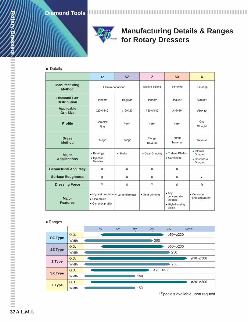
Manufacturing Details & Ranges for Rotary Dressers
■ Details
ManufacturingMethod
Diamond GritDistribution
ApplicableGrit Size
Profile
DressMethod
MajorApplications
Geometrical Accuracy
Surface Roughness
Dressing Force
RZ
Electro-deposition
Random
#20~#140
Complex
Fine
● Bearings
● Injection Needles
○
Plunge
Z
Electro-plating
● Gear Grinding
Random
Form
Plunge
Traverse
○
○
○
#30~#140
SZ
Regular
#16~#20
Plunge
Form
○
○
● Shafts
Form
SX
Sintering
Regular
#16~20
Plunge
Traverse
○
○
● Turbine Blades
● Camshafts
X
● Internal Grinding
● Centerless Grinding
Random
Traverse
MajorFeatures
● Highest precision
● Fine profile
● Complex profile
● Gear grinding● Large diameter ● Any concentration settable
● High dressing ability
● Consistant dressing ability
#30~80
Cup
Straight
-
Sintering
�
ø20~ø300
ø20~ø180
ø10~ø300
ø50~ø230
■ Ranges
RZ TypeO.D.
SZ Type
Z Type
SX Type
X Type
Width
O.D.
Width
O.D.
Width
O.D.
Width
O.D.
Width
50 100 150 200 250 300mm
200
250
250
150
150
ø50~ø230
*Specials available upon request
38
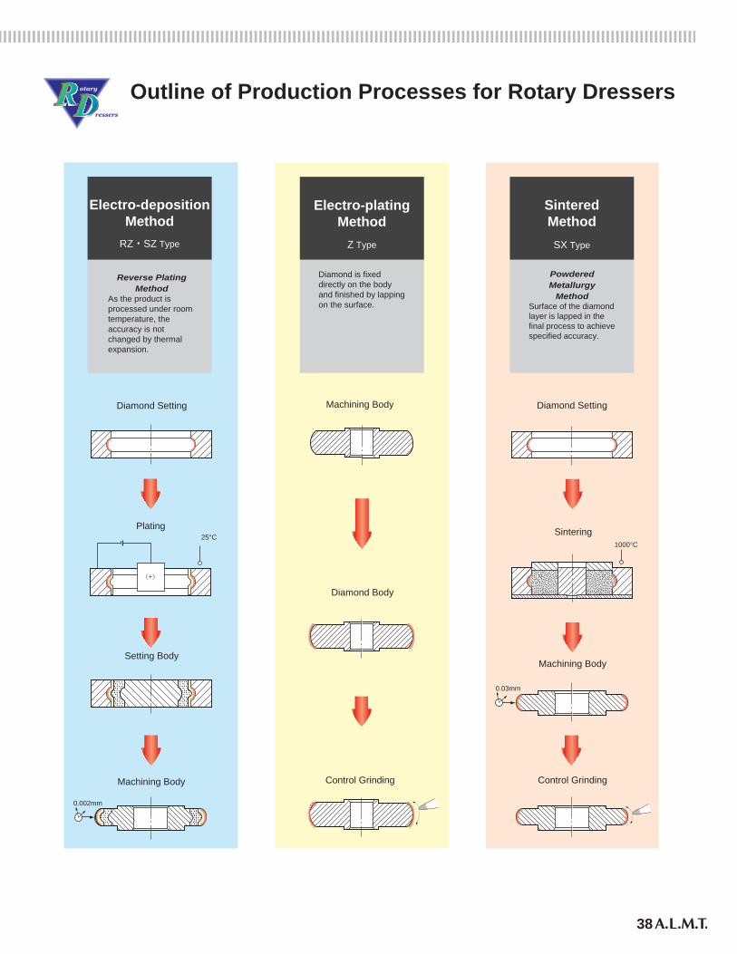
Outline of Production Processes for Rotary Dressers
Reverse Plating Method
As the product is processed under room temperature, the accuracy is not changed by thermal expansion.
Electro-depositionMethod
RZ・SZ Type
Diamond Setting
Plating25°C
(+)
Setting Body
Machining Body
0.002mm
Diamond is fixed directly on the body and finished by lapping on the surface.
Electro-platingMethod
Z Type
Diamond Body
Control Grinding
Machining Body
Powdered Metallurgy
MethodSurface of the diamond layer is lapped in the final process to achieve specified accuracy.
SinteredMethod
SX Type
Machining Body
0.03mm
Diamond Setting
Sintering1000°C
Control Grinding
39
Rotary D
ressers
Diamond Tools
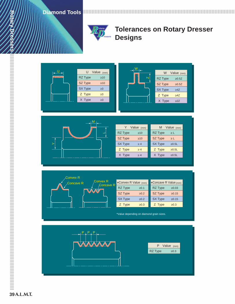
Tolerances on Rotary Dresser Designs
RZ Type ≥10
U Value
SZ Type ≥10
SX Type ≥3
Z Type ≥3
X Type ≥3
U (mm)
RZ Type
W Value
SZ Type ≥0.5Z
SX Type ≥4Z
Z Type ≥4Z
X Type ≥2Z
(mm)
≥0.5Z
RZ Type
Y Value
SZ Type ≥10
SX Type ≥ 4
Z Type ≥ 4
X Type ≥ 4
(mm)
≥10 RZ Type
M Value
SZ Type ≥ L
SX Type ≥0.5L
Z Type ≥0.5L
X Type ≥0.5L
(mm)
≥ L
RZ Type*Convex R Value
SZ Type ≥0.2
SX Type ≥0.2
Z Type ≥0.3
(mm)
≥0.1 RZ Type*Concave R Value
SZ Type ≥0.15
SX Type ≥0.15
Z Type ≥0.3
(mm)
≥0.03
RZ Type
P Value (mm)
≥0.3
W
Z
M
Y
L
Concave R Convex RConcave R
Convex R
P P P
*Value depending on diamond grain sizes.
40
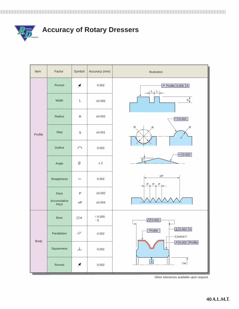
Accuracy of Rotary Dressers
Other tolerances available upon request
Runout 0.002
Width ±0.005L
Radius ±0.002R
Step ±0.001S
Outline 0.002
Angle ± 2́
Straightness 0.002
Pitch
AccumulativePitch
±0.002P
±0.004nP
Parallelism 0.002
Bore +0.005-0
H
Squareness 0.002
Runout 0.002
Profile
Body
0.002
Item Factor Symbol Accuracy (mm) Illustration
S
L L
A0.005Profile
RR R
0.002
P P P
nP
Profile
H
Control
0.002
Profile
0.002
A
A
0.002
41
Rotary D
ressers
Diamond Tools
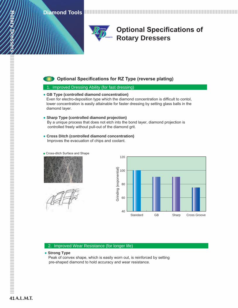
Optional Specifications of Rotary Dressers
1. Improved Dressing Ability (for fast dressing)
2. Improved Wear Resistance (for longer life)
● GB Type (controlled diamond concentration) Even for electro-deposition type which the diamond concentration is difficult to contol, lower concentration is easily attainable for faster dressing by setting glass balls in the diamond layer.
● Sharp Type (controlled diamond projection) By a unique process that does not etch into the bond layer, diamond projection is controlled freely without pull-out of the diamond grit.
● Cross Ditch (controlled diamond concentration) Improves the evacuation of chips and coolant.
Optional Specifications for RZ Type (reverse plating)
■ Cross-ditch Surface and Shape
40Standard SharpGB
60
80
100
120
Cross Groove
Grin
ding
(exp
onen
tial)
● Strong Type Peak of convex shape, which is easily worn out, is reinforced by setting pre-shaped diamond to hold accuracy and wear resistance.
42
3. For Improving Wear Resistance
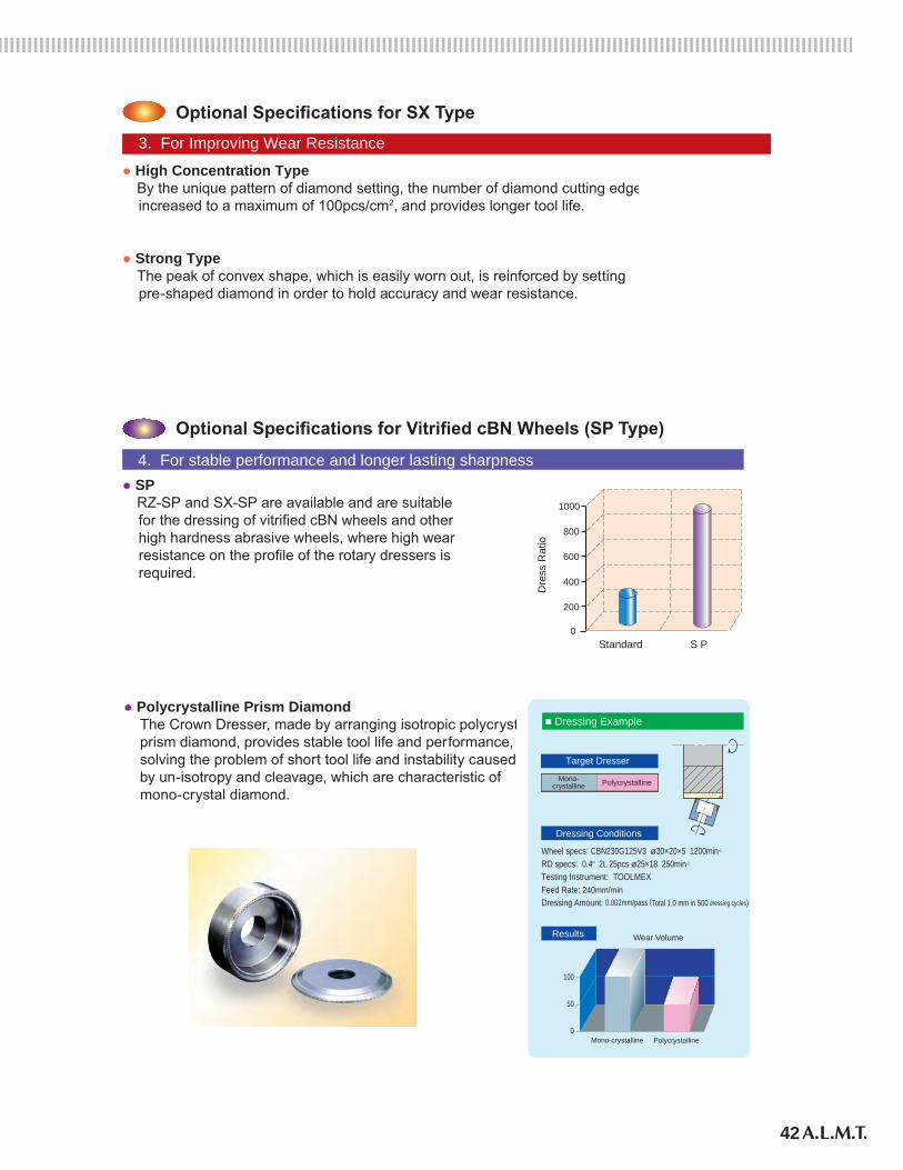
Optional Specifications for SX Type
● High Concentration Type By the unique pattern of diamond setting, the number of diamond cutting edges is increased to a maximum of 100pcs/cm2, and provides longer tool life.
● Strong Type The peak of convex shape, which is easily worn out, is reinforced by setting pre-shaped diamond in order to hold accuracy and wear resistance.
Optional Specifications for Vitrified cBN Wheels (SP Type)
4. For stable performance and longer lasting sharpness● SP RZ-SP and SX-SP are available and are suitable for the dressing of vitrified cBN wheels and other high hardness abrasive wheels, where high wear resistance on the profile of the rotary dressers is required.
0
200
400
600
800
1000
Standard S P
Dre
ss R
atio
● Polycrystalline Prism Diamond The Crown Dresser, made by arranging isotropic polycrystaline prism diamond, provides stable tool life and performance, solving the problem of short tool life and instability caused by un-isotropy and cleavage, which are characteristic of mono-crystal diamond.
Target Dresser
Wheel specs: CBN230G125V3 ø30×20×5 1200min-1
RD specs: 0.4 2L 25pcs ø25×18 250min-1
Testing Instrument: TOOLMEXFeed Rate: 240mm/minDressing Amount: 0.002mm/pass (Total 1.0 mm in 500 dressing cycles)
Results
Dressing Conditions
100
50
0
Mono-crystalline Polycrystalline
Wear Volume
Mono-crystalline
■ Dressing Example
Polycrystalline
43
Rotary D
ressers
Diamond Tools
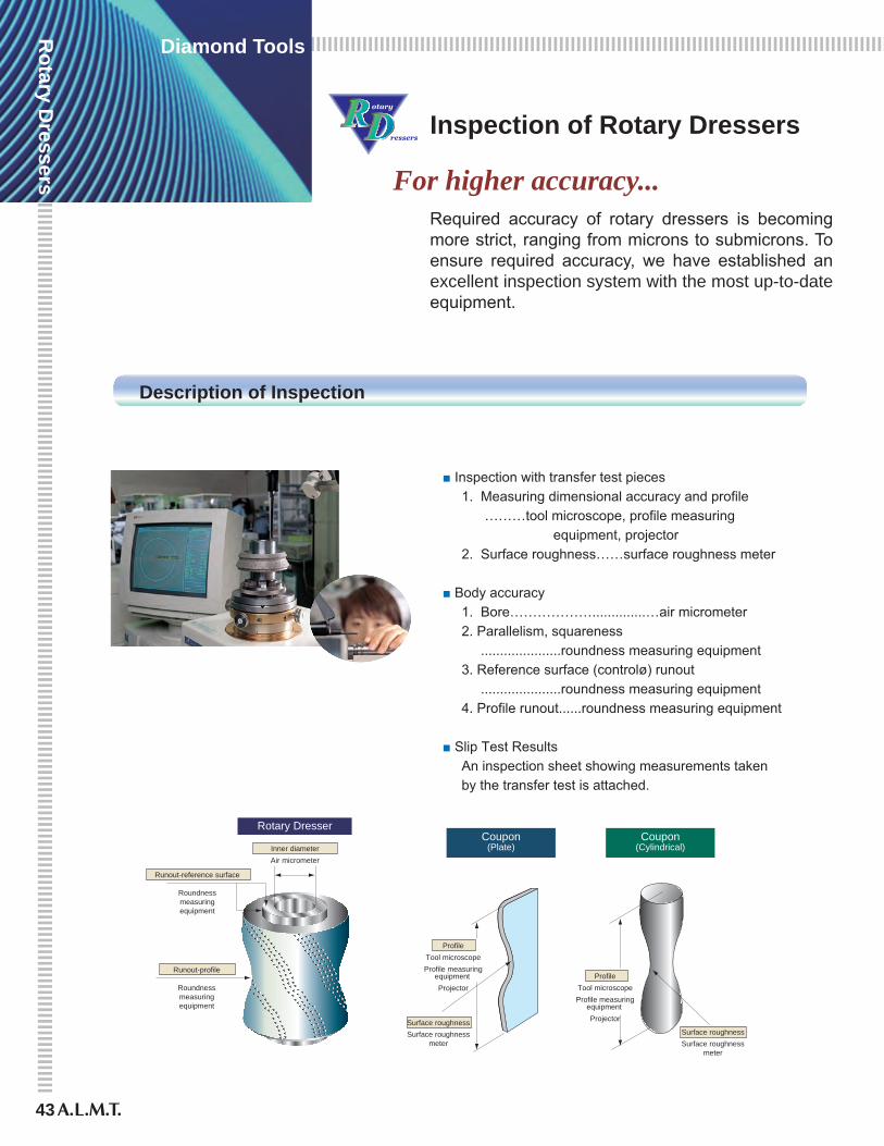
Inspection of Rotary Dressers
For higher accuracy...Required accuracy of rotary dressers is becoming more strict, ranging from microns to submicrons. To ensure required accuracy, we have established an excellent inspection system with the most up-to-date equipment.
Description of Inspection
■ Inspection with transfer test pieces 1. Measuring dimensional accuracy and profile ………tool microscope, profile measuring equipment, projector 2. Surface roughness……surface roughness meter
■ Body accuracy 1. Bore………………..............…air micrometer 2. Parallelism, squareness .....................roundness measuring equipment 3. Reference surface (controlø) runout .....................roundness measuring equipment 4. Profile runout......roundness measuring equipment
■ Slip Test Results An inspection sheet showing measurements taken by the transfer test is attached.
Coupon(Plate)
Coupon(Cylindrical)
Rotary Dresser
Runout-reference surface
Roundnessmeasuringequipment
Runout-profile
Roundnessmeasuringequipment
ProfileTool microscopeProfile measuring
equipment Projector
ProfileTool microscopeProfile measuring
equipment ProjectorSurface roughness
Surface roughnessmeter
Inner diameterAir micrometer
Surface roughnessSurface roughness
meter
44
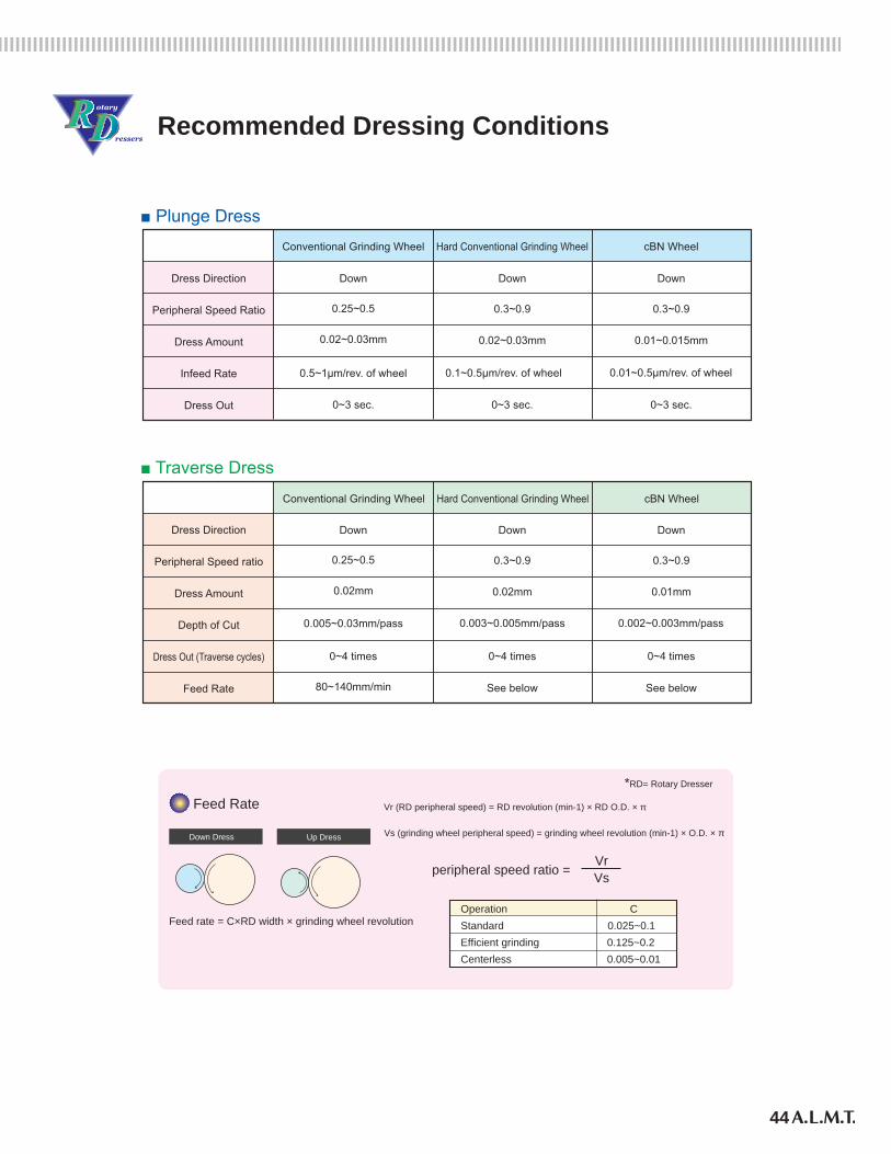
Recommended Dressing Conditions
■ Plunge Dress
Dress Direction
Peripheral Speed Ratio
Dress Amount
Infeed Rate
Dress Out
Conventional Grinding Wheel
Down
0.25~0.5
0.02~0.03mm
0.5~1μm/rev. of wheel
0~3 sec.
Hard Conventional Grinding Wheel
Down
0.3~0.9
0.02~0.03mm
0.1~0.5μm/rev. of wheel
0~3 sec.
cBN Wheel
Down
0.3~0.9
0.01~0.015mm
0~3 sec.
■ Traverse Dress
Dress Direction
Peripheral Speed ratio
Dress Amount
Depth of Cut
Dress Out (Traverse cycles)
Feed Rate
0.25~0.5
0.02mm
0.005~0.03mm/pass
0~4 times
0.3~0.9
0.02mm
0.003~0.005mm/pass
0~4 times
0.3~0.9
0.01mm
0.002~0.003mm/pass
0~4 times
80~140mm/min See below See below
0.01~0.5μm/rev. of wheel
Conventional Grinding Wheel Hard Conventional Grinding Wheel cBN Wheel
Down Down Down
Down Dress Up Dress
Vr (RD peripheral speed) = RD revolution (min-1) × RD O.D. × π
Vs (grinding wheel peripheral speed) = grinding wheel revolution (min-1) × O.D. × π
peripheral speed ratio = Vr Vs
Feed rate = C×RD width × grinding wheel revolution
Feed Rate
Operation CStandard 0.025~0.1Efficient grinding 0.125~0.2Centerless 0.005~0.01
*RD= Rotary Dresser
45
Rotary D
ressers
Diamond Tools
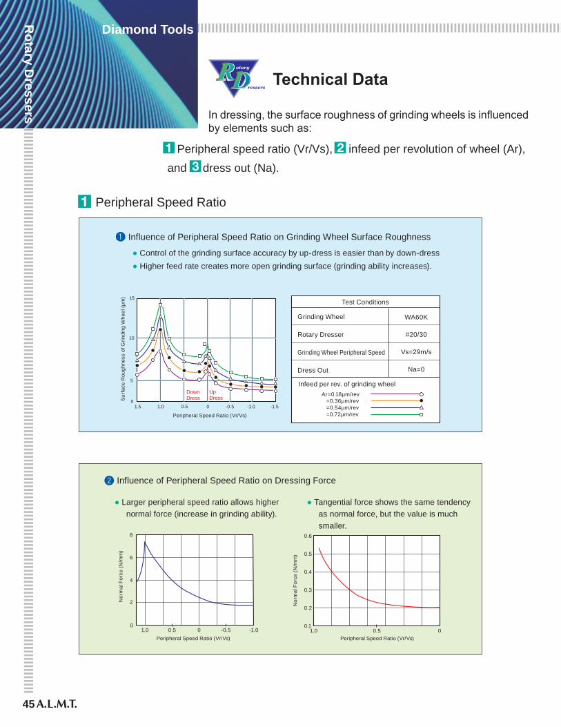
Technical Data
In dressing, the surface roughness of grinding wheels is influenced by elements such as:
Peripheral speed ratio (Vr/Vs), infeed per revolution of wheel (Ar), and dress out (Na).
I Influence of Peripheral Speed Ratio on Grinding Wheel Surface Roughness
15
10
5
01.5 1.0 0.5 0 -0.5 -1.0 -1.5
Peripheral Speed Ratio (Vr/Vs)
Sur
face
Rou
ghne
ss o
f Grin
ding
Whe
el (μ
m)
DownDress
UpDress
WA60K
#20/30
Vs=29m/s
Na=0
Test Conditions
Grinding Wheel
Rotary Dresser
Grinding Wheel Peripheral Speed
Dress Out
● Control of the grinding surface accuracy by up-dress is easier than by down-dress● Higher feed rate creates more open grinding surface (grinding ability increases).
Peripheral Speed Ratio
Infeed per rev. of grinding wheelAr=0.18μm/rev =0.36μm/rev =0.54μm/rev =0.72μm/rev
Influence of Peripheral Speed Ratio on Dressing Force
Peripheral Speed Ratio (Vr/Vs)Peripheral Speed Ratio (Vr/Vs)
Nor
mal
For
ce (N
/mm
)
0.11.0 0.5 0
0.2
0.3
0.4
0.5
0.6
Nor
mal
For
ce (N
/mm
)
01.0 0.5 -0.5 -1.00
2
4
6
8
● Larger peripheral speed ratio allows higher normal force (increase in grinding ability).
● Tangential force shows the same tendency as normal force, but the value is much smaller.
46
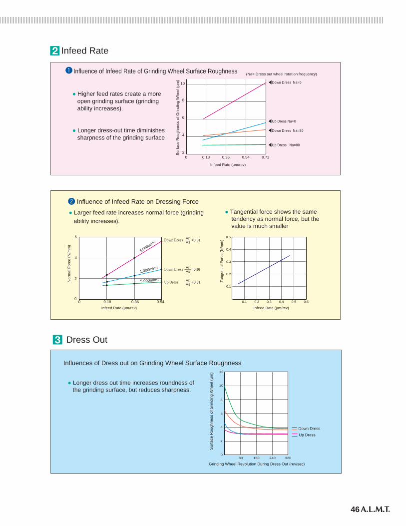
Influence of Infeed Rate of Grinding Wheel Surface Roughness
0 0.18 0.36 0.54 0.72
4
2
6
8
10
● Higher feed rates create a more open grinding surface (grinding ability increases).
● Longer dress-out time diminishes sharpness of the grinding surface
(Na= Dress out wheel rotation frequency)
Infeed Rate
Infeed Rate (μm/rev)
Sur
face
Rou
ghne
ss o
f Grin
ding
Whe
el (μ
m) Down Dress Na=0
Up Dress Na=0
Down Dress Na=80
Up Dress Na=80
0.1
0.1 0.2 0.3 0.4 0.5 0.6
0.2
0.3
0.4
0.5
Influence of Infeed Rate on Dressing Force
● Larger feed rate increases normal force (grinding ability increases).
● Tangential force shows the same tendency as normal force, but the value is much smaller
Nor
mal
For
ce (N
/mm
)
Tang
entia
l For
ce (N
/mm
)
5,000min-1
1,000min-1
5,000min-1
0 0.18 0.36 0.540
2
4
6
Infeed Rate (μm/rev) Infeed Rate (μm/rev)
VsVrDown Dress =0.81
VsVrDown Dress =0.16
VsVrUp Dress =0.81
12
10
8
6
4
2
080 150 240 320
Grinding Wheel Revolution During Dress Out (rev/sec)
Sur
face
Rou
ghne
ss o
f Grin
ding
Whe
el (μ
m)
Down DressUp Dress
Influences of Dress out on Grinding Wheel Surface Roughness
● Longer dress out time increases roundness of the grinding surface, but reduces sharpness.
Dress Out
Grinding Rotary Dresser
47
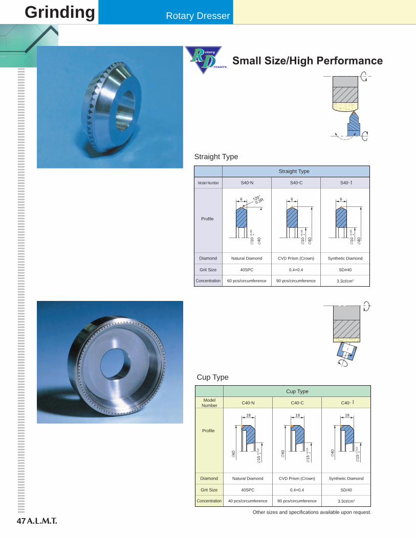
Small Size/High Performance
Straight Type
Straight Type
S40-N S40-C S40- Model Number
Profile
Natural Diamond CVD Prism (Crown) Synthetic DiamondDiamond
40SPC 0.4×0.4 SD#40Grit Size
60 pcs/circumference 90 pcs/circumference 3.3ct/cm3Concentration
6
40
10
+0.0
05 0
6
40
10
+0.0
05 0
6
40
10
+0.0
05 0
Cup Type
Cup Type
C40-N C40-C C40- ModelNumber
Profile
Natural Diamond CVD Prism (Crown) Synthetic DiamondDiamond
40SPC 0.4×0.4 SD/40Grit Size
40 pcs/circumference 90 pcs/circumference 3.3ct/cm3Concentration
1818
40
15
+0.0
18 0
18
Other sizes and specifications available upon request.
15
+0.0
18 0
15
+0.0
18 0
40
40
Crown Dresser
48
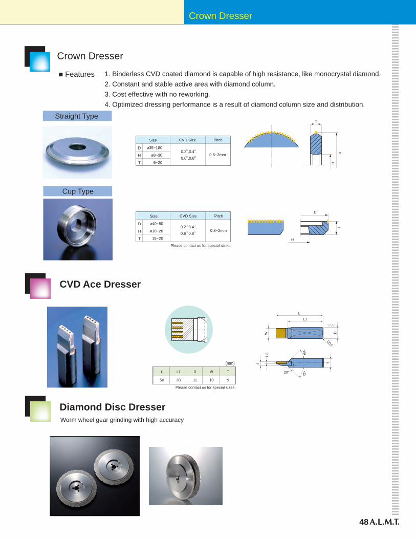
Please contact us for special sizes.
L
50
L1
38
D
11
W
10
T
9
CO.5
LL1
W D
1.8
4 T
20°
45°
45L
(mm)
CVD Ace Dresser
Diamond Disc DresserWorm wheel gear grinding with high accuracy
Crown Dresser
Straight Type
Cup Type
0.8~2mm
D
H
T
0.2□,0.4□,
0.6□,0.8□
ø35~180
ø8~30
6~20
Size CVD Size Pitch
D
H
T
T
D
H
0.2□,0.4□,
0.6□,0.8□ 0.8~2mm
D
H
T
ø40~80
ø10~20
15~20
1. Binderless CVD coated diamond is capable of high resistance, like monocrystal diamond.2. Constant and stable active area with diamond column.3. Cost effective with no reworking.4. Optimized dressing performance is a result of diamond column size and distribution.
■ Features
Size CVD Size Pitch
Please contact us for special sizes.
49
Monocrystal
Diamond Tools
Precision Cutting Tools
50
Monocrystal
Diamond Tools
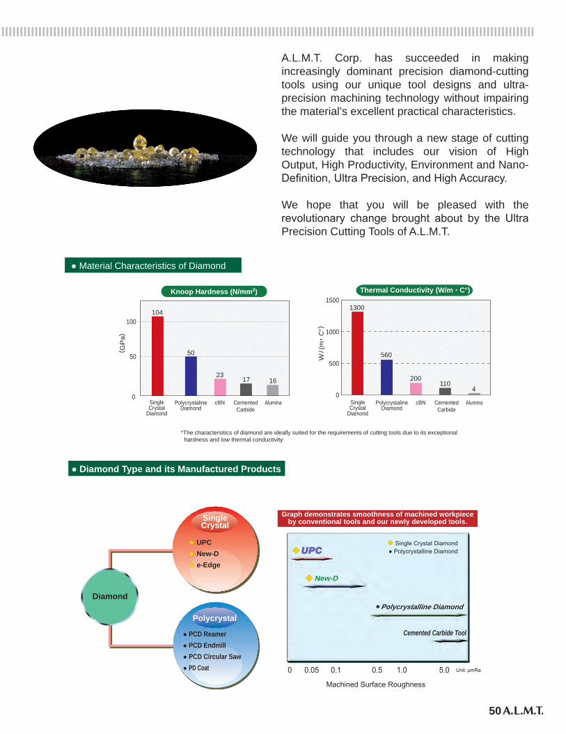
A.L.M.T. Corp. has succeeded in making increasingly dominant precision diamond-cutting tools using our unique tool designs and ultra-precision machining technology without impairing the material’s excellent practical characteristics.
We will guide you through a new stage of cutting technology that includes our vision of High Output, High Productivity, Environment and Nano-Definition, Ultra Precision, and High Accuracy.
We hope that you will be pleased with the revolutionary change brought about by the Ultra Precision Cutting Tools of A.L.M.T.
*The charactersitics of diamond are ideally suited for the requirements of cutting tools due to its exceptional hardness and low thermal conductivity
40
500
1000
15001300
560
200110
4
● Material Characteristics of Diamond
SingleCrystal
Diamond
PolycrystalineDiamond
cBN CementedCarbide
Alumina0
50
100
( GP
a)
W/(
m・C
°)104
50
2317 16
Knoop Hardness (N/mm2) Thermal Conductivity (W/m . C°)
SingleCrystal
Diamond
PolycrystalineDiamond
cBN CementedCarbide
Alumina
0 0.05 0.1 0.5 1.0 5.0 Unit: μmRa
Graph demonstrates smoothness of machined workpieceby conventional tools and our newly developed tools.
Polycrystalline Diamond
New-D
◆� Single Crystal Diamond
◆
●
● Polycrystalline Diamond
Machined Surface Roughness
Diamond
� UPC� New-D� e-Edge
SingleCrystal
Polycrystal
● PCD Reamer● PCD Endmill● PCD Circular Saw● PD Coat
● Diamond Type and its Manufactured Products
Cemented Carbide Tool
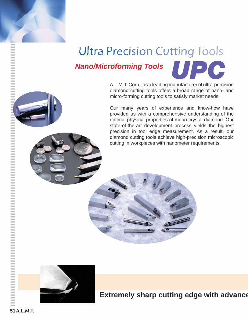
A.L.M.T. Corp., as a leading manufacturer of ultra-precision diamond cutting tools offers a broad range of nano- and micro-forming cutting tools to satisfy market needs.
Our many years of experience and know-how have provided us with a comprehensive understanding of the optimal physical properties of mono-crystal diamond. Our state-of-the-art development process yields the highest precision in tool edge measurement. As a result, our diamond cutting tools achieve high-precision microscopic cutting in workpieces with nanometer requirements.
Extremely sharp cutting edge with advanced UPC cutting tools
Nano/Microforming Tools
51
52
500nm
Cutting edge shape
a
a
22 a
41 a
a
22 a
42 a
22 a
122 a
43 a
(100) (110) (111)
a a
Anisotropy of the atomic distance
Waviness44.5nm
Manu. No.Window Angle 90°00′Corner Radius 0.052mmCorner Height 4.120mm
250nm
250nm
125nm
125nm
22°30′ 0 22°30′45°45°
Width of 15μm tip of Nano endmill
100μm
Mea
surin
g Te
chno
logy
Use
d fo
r Dia
mon
d Se
lect
ion
Polis
hing
and
Mea
surin
g Te
chno
logy
Nano
-cut
ting
and
Mic
ro-c
uttin
g Te
chno
logy
Diamond Lattice Model
X-ray photography ofsingle crystal diamond
Sharply polishedmonocrystal diamond Extremely fine chips measured
down to nanometer dimensions
Polished surface shown in the same magnfication
4μm
Molds surface by microforming
Contour inspection sheet
Extremely sharp cutting edge with advanced UPC cutting tools
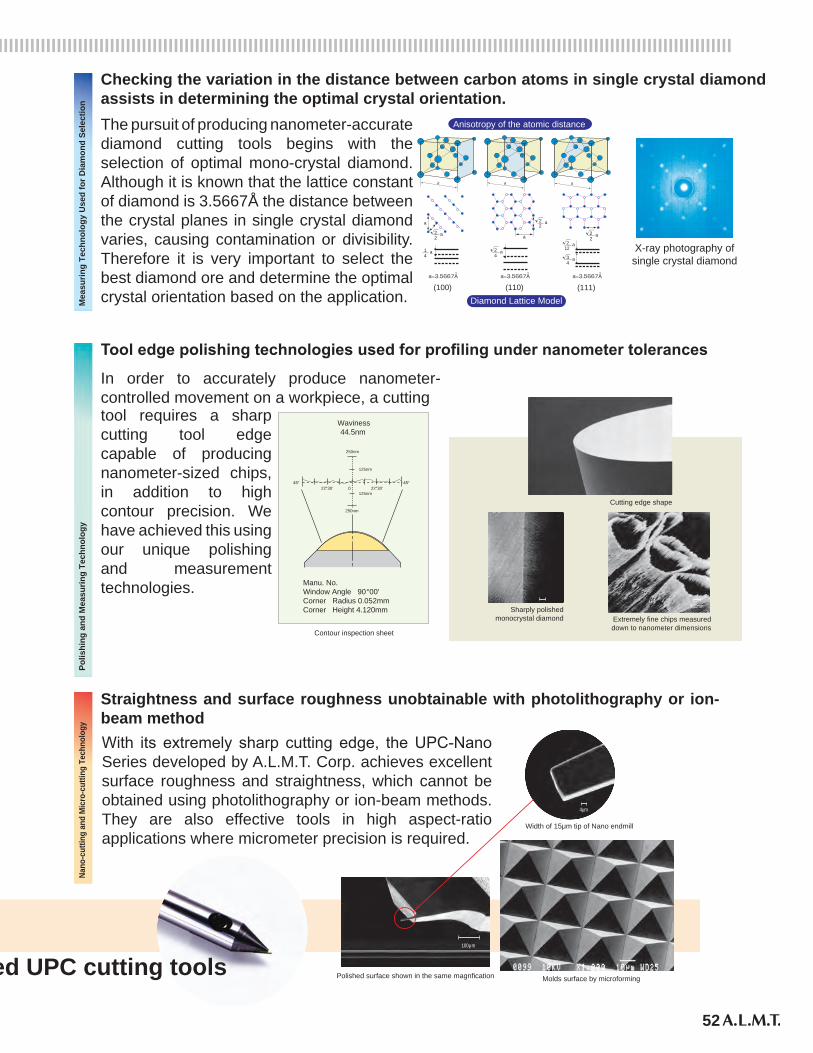
Checking the variation in the distance between carbon atoms in single crystal diamond assists in determining the optimal crystal orientation.The pursuit of producing nanometer-accurate diamond cutting tools begins with the selection of optimal mono-crystal diamond. Although it is known that the lattice constant of diamond is 3.5667Å the distance between the crystal planes in single crystal diamond varies, causing contamination or divisibility. Therefore it is very important to select the best diamond ore and determine the optimal crystal orientation based on the application.
Tool edge polishing technologies used for profiling under nanometer tolerances
In order to accurately produce nanometer-controlled movement on a workpiece, a cuttingtool requires a sharp cutting tool edge capable of producing nanometer-sized chips, in addition to high contour precision. We have achieved this using our unique polishing and measurement technologies.
Straightness and surface roughness unobtainable with photolithography or ion-beam methodWith its extremely sharp cutting edge, the UPC-Nano Series developed by A.L.M.T. Corp. achieves excellent surface roughness and straightness, which cannot be obtained using photolithography or ion-beam methods. They are also effective tools in high aspect-ratio applications where micrometer precision is required.
53
Cutting Nano Microforming
Nano/Microforming Tools
Straightness and surface roughness unobtainable with photolithography or ion-beam method
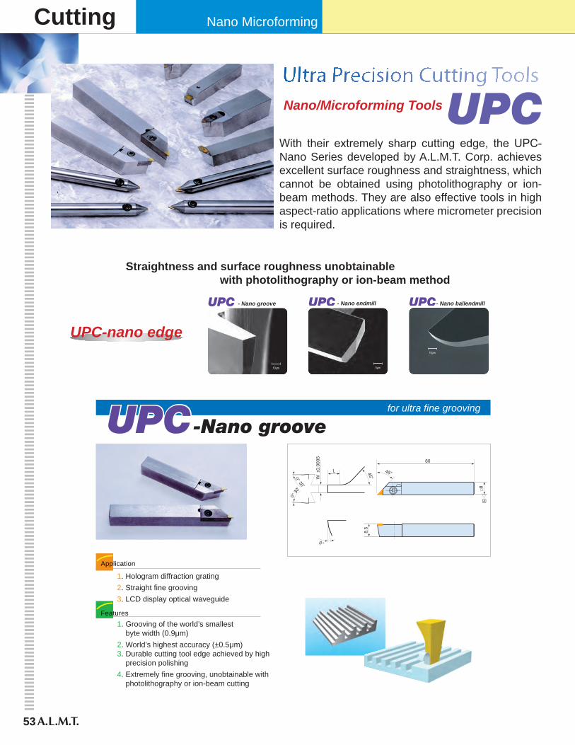
With their extremely sharp cutting edge, the UPC-Nano Series developed by A.L.M.T. Corp. achieves excellent surface roughness and straightness, which cannot be obtained using photolithography or ion-beam methods. They are also effective tools in high aspect-ratio applications where micrometer precision is required.
10μm 5μm
10μm
for ultra fine grooving
1. Hologram diffraction grating2. Straight fine grooving3. LCD display optical waveguide
1. Grooving of the world’s smallest byte width (0.9μm)2. World’s highest accuracy (±0.5μm)3. Durable cutting tool edge achieved by high precision polishing4. Extremely fine grooving, unobtainable with photolithography or ion-beam cutting
Application
Features
45°
60
8.5
L
W ±
0.00
05
45°0° 30 ,
0° 3
0,
□8
□A
°
- Nano groove - Nano endmill - Nano ballendmill
UPC-nano edge
54
UPC
Square type
45°
50
165 G
(0.5)
(1)
ø6
øA ±
0.01
B
0°± 1
°
Detail drawing the blade (100/1)
°
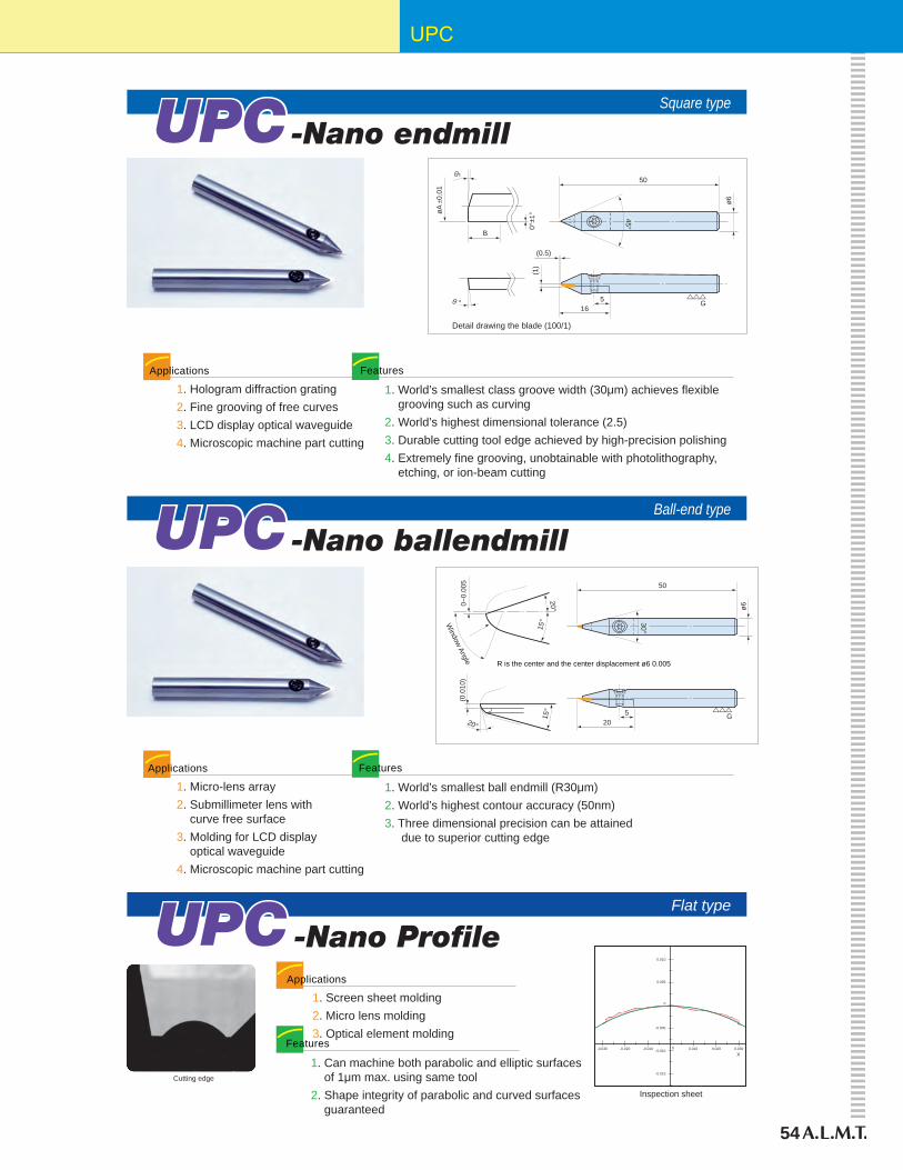
1. World’s smallest class groove width (30μm) achieves flexible grooving such as curving2. World’s highest dimensional tolerance (2.5)3. Durable cutting tool edge achieved by high-precision polishing4. Extremely fine grooving, unobtainable with photolithography, etching, or ion-beam cutting
1. Hologram diffraction grating2. Fine grooving of free curves3. LCD display optical waveguide4. Microscopic machine part cutting
FeaturesApplications
Ball-end type
ø6
(0.0
10)
15°
20°
30°
205 G
50
0~0.
005
20°
15°W
indow Angle R is the center and the center displacement ø6 0.005
1. World’s smallest ball endmill (R30μm)2. World’s highest contour accuracy (50nm)3. Three dimensional precision can be attained due to superior cutting edge
1. Micro-lens array2. Submillimeter lens with curve free surface3. Molding for LCD display optical waveguide4. Microscopic machine part cutting
FeaturesApplications
Flat type
Cutting edge
0.010
0.005
0
-0.005
-0.015
-0.010 0.0100-0.010-0.020-0.030
X0.0300.020
Inspection sheet
1. Can machine both parabolic and elliptic surfaces of 1μm max. using same tool2. Shape integrity of parabolic and curved surfaces guaranteed
1. Screen sheet molding2. Micro lens molding3. Optical element molding
Features
Applications
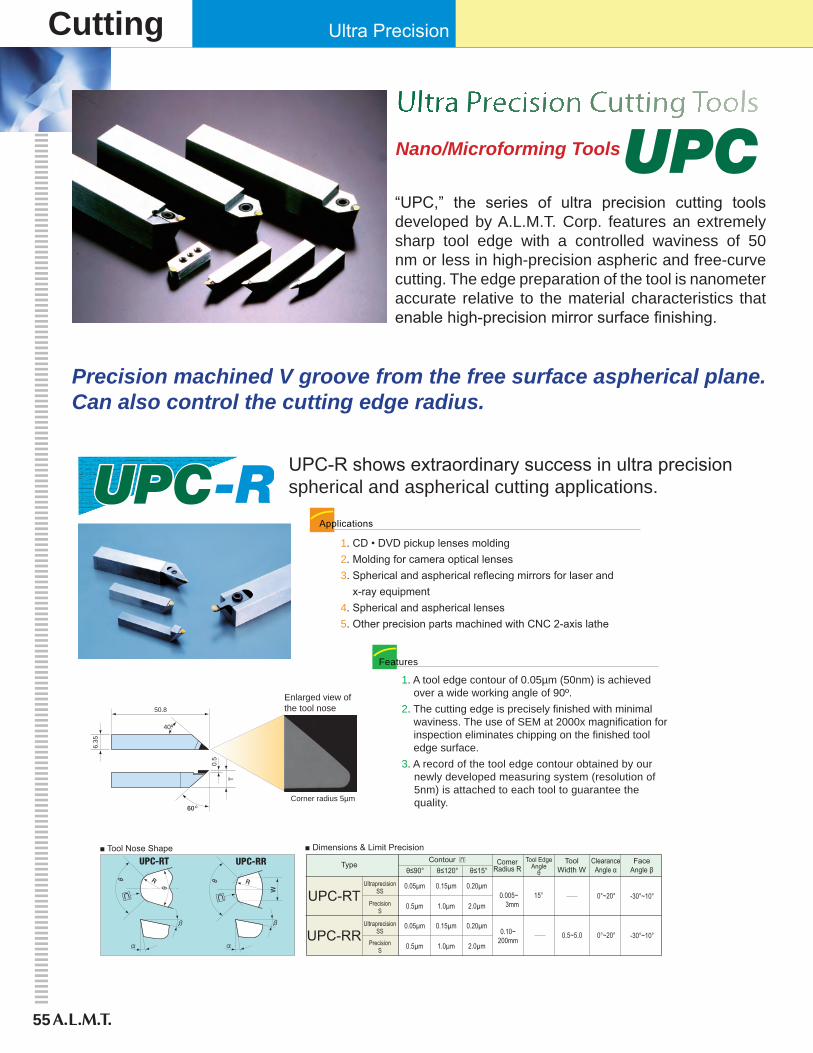
55
Cutting Ultra Precision
Nano/Microforming Tools
“UPC,” the series of ultra precision cutting tools developed by A.L.M.T. Corp. features an extremely sharp tool edge with a controlled waviness of 50 nm or less in high-precision aspheric and free-curve cutting. The edge preparation of the tool is nanometer accurate relative to the material characteristics that enable high-precision mirror surface finishing.
Precision machined V groove from the free surface aspherical plane.Can also control the cutting edge radius.
UPC-R shows extraordinary success in ultra precision spherical and aspherical cutting applications.
1. CD • DVD pickup lenses molding2. Molding for camera optical lenses3. Spherical and aspherical reflecing mirrors for laser and x-ray equipment4. Spherical and aspherical lenses5. Other precision parts machined with CNC 2-axis lathe
Applications
1. A tool edge contour of 0.05µm (50nm) is achieved over a wide working angle of 90º.2. The cutting edge is precisely finished with minimal waviness. The use of SEM at 2000x magnification for inspection eliminates chipping on the finished tool edge surface.3. A record of the tool edge contour obtained by our newly developed measuring system (resolution of 5nm) is attached to each tool to guarantee the quality.
Features
0.5
6.35
T
50.8
Corner radius 5µm
40º
Enlarged view ofthe tool nose
º
ToolWidth W
FaceAngle β
ClearanceAngle α
Tool EdgeAngle
θCorner
Radius RContour
Typeθ≤90° θ≤15°θ≤120°
UltraprecisionSS
PrecisionS
UltraprecisionSS
PrecisionS
UPC-RT
UPC-RR
0.05μm 0.15μm 0.20μm0.005~ 3mm0.5μm 1.0μm 2.0μm
0.05μm 0.15μm 0.20μm
0.5μm 1.0μm 2.0μm
15° 0°~20° -30°~10°
0.10~200mm
0°~20°0.5~5.0 -30°~10°
■ Tool Nose Shape ■ Dimensions & Limit Precision
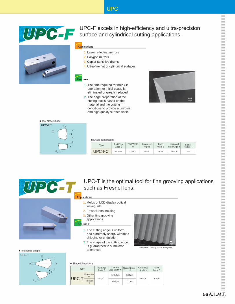
56
UPC
UPC-F excels in high-efficiency and ultra-precision surface and cylindrical cutting applications.
100μm
1. Laser reflecting mirrors2. Polygon mirrors3. Copier sensitive drums4. Ultra-fine flat or cylindrical surfaces
Applications
1. The time required for break-in operation for initial usage is eliminated or greatly reduced.2. The edge preparation of the cutting tool is based on the material and the cutting conditions to provide a uniform and high quality surface finish.
Features
W
UPC-FC
Tool WidthW
FaceAngle β
HorizontalFace Angle Y
ClearanceAngle α
Tool EdgeAngle θ
CornerRadius R
Type
UPC-FC 0°~15°-5°~0°0°~5°45°~80° 1.0~4.0
■ Tool Nose Shape
■ Shape Dimensions
Molds of LCD display optical waveguide
UPC-T
10μm
1. Molds of LCD display optical waveguide2. Fresnel lens molding3. Other fine grooving applications
■ Tool Nose Shape
■ Shape Dimensions
1. The cutting edge is uniform and extremely sharp, without c chipping or undulation2. The shape of the cutting edge is guaranteed to submicron tolerances
Features
LeadingEdge Width W
FaceAngle β
ClearanceAngle α
Tool EdgeAngle θ
Type
UPC-T -5°~10°0°~15°0.05μm
min20°min0.2μm
0.1μmmin2μm
Straightness □
UltraprecisionSS
PrecisionS
Applications
UPC-T is the optimal tool for fine grooving applications such as Fresnel lens.
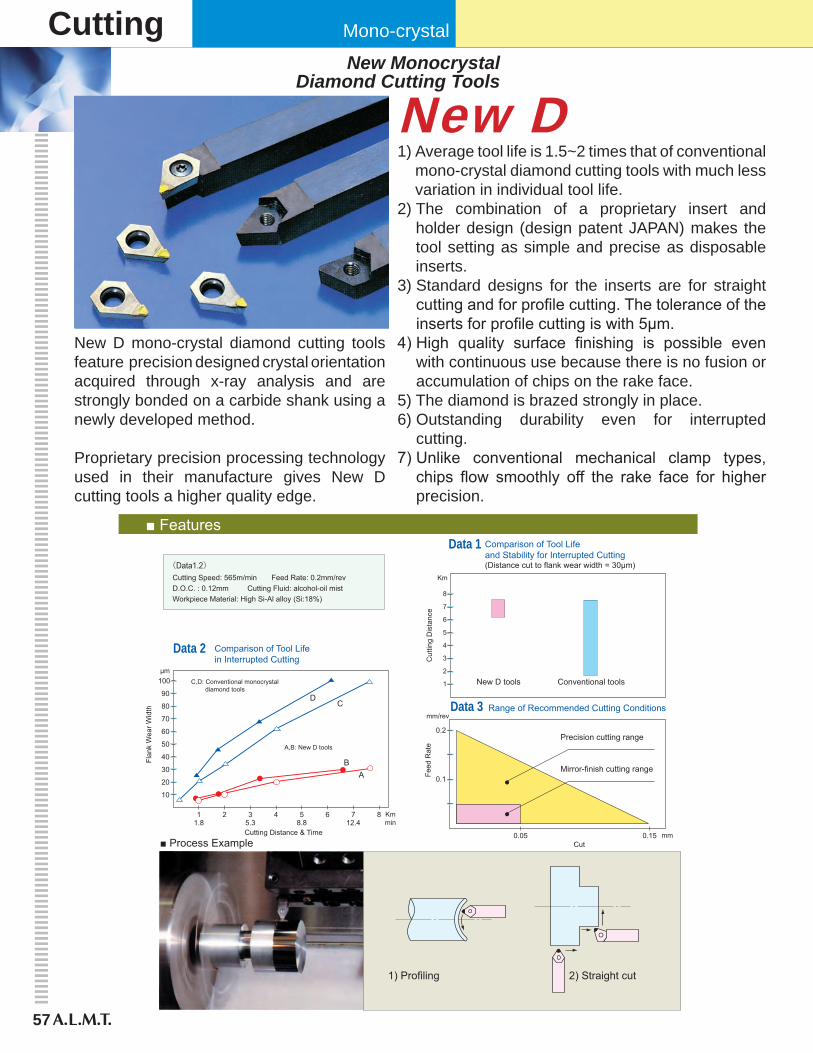
57
Cutting Mono-crystal
New DNew Monocrystal
Diamond Cutting Tools
New D mono-crystal diamond cutting tools feature precision designed crystal orientation acquired through x-ray analysis and are strongly bonded on a carbide shank using a newly developed method.
Proprietary precision processing technology used in their manufacture gives New D cutting tools a higher quality edge.
■ Features Data 1 Comparison of Tool Life
and Stability for Interrupted Cutting(Distance cut to flank wear width = 30µm)
Data 2 Comparison of Tool Lifein Interrupted Cutting
Data 3 Range of Recommended Cutting Conditions
(Data1.2)Cutting Speed: 565m/min Feed Rate: 0.2mm/revD.O.C. : 0.12mm Cutting Fluid: alcohol-oil mistWorkpiece Material: High Si-Al alloy (Si:18%)
8
7
6
5
4
3
2
1
Cut
ting
Dis
tanc
e
New D tools Conventional tools
Km
10
20
30
40
50
60
70
80
90
100
Flan
k W
ear W
idth
A,B: New D tools
C,D: Conventional monocrystal diamond tools
μm
A
DC
B
11.8
2 35.3
4 58.8
6 712.4
8 Kmmin
Cutting Distance & Time
0.1
0.2
Feed
Rat
e
mm/rev
0.05 0.15 mmCut
Precision cutting range
Mirror-finish cutting range
■ Process Example
1) Profiling 2) Straight cut
1) Average tool life is 1.5~2 times that of conventional mono-crystal diamond cutting tools with much less variation in individual tool life.
2) The combination of a proprietary insert and holder design (design patent JAPAN) makes the tool setting as simple and precise as disposable inserts.
3) Standard designs for the inserts are for straight cutting and for profile cutting. The tolerance of the inserts for profile cutting is with 5µm.
4) High quality surface finishing is possible even with continuous use because there is no fusion or accumulation of chips on the rake face.
5) The diamond is brazed strongly in place.6) Outstanding durability even for interrupted
cutting.7) Unlike conventional mechanical clamp types,
chips flow smoothly off the rake face for higher precision.
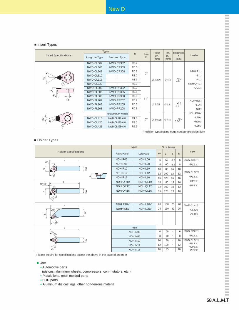
58
New D
NDH-R1□ -L1□ -N1□
NDH-QR1□ -QL1□
NDH-RO□ -LO□ -NO□
NDH-R20V -L20V -R25V -L25V
Insert Specifications
■ Insert Types
Types
NWD-CL302NWD-CL305NWD-CL308NWD-CL310NWD-CL316NWD-CL320NWD-PL302NWD-PL305NWD-PL308NWD-PL202NWD-PL205NWD-PL208
NWD-CL416NWD-CL420NWD-CL425
NWD-CP302NWD-CP305NWD-CP308
---
NWD-PP302NWD-PP305NWD-PP308NWD-PP202NWD-PP205NWD-PP208
NWD-CL416-AWNWD-CL420-AWNWD-CL425-AW
R0.2R0.5R0.8R1.0R1.6R2.0R0.2R0.5R0.8R0.2R0.5R0.8
R1.6R2.0R2.5
Long Life Type Precision Type R Relief
øA(mm)
I.H.øB
(mm)
Thicknessh
(mm)Holder
9.525 4.4 +0.2 4-0
6.35
9.525
2.8
4.4
Precision type/cutting edge contour precision 5μm
Holder Specifications
■ Holder Types
NWD-PP2□□ -PL2□□
NWD-CL3□□
-PL3□□
-CP3□□
-PP3□□
NWD-CL416
-CL420
-CL425
NWD-PP2□□
-PL2□□
NWD-CL3□□ -PL3□□ -CP3□□ -PP3□□
Size (mm)Types
NDH-R06NDH-R08
NDH-R10NDH-R12NDH-R16NDH-QR10NDH-QR12NDH-QR16
NDH-R20VNDH-R25V
NDH-N06NDH-N08NDH-N10NDH-N12NDH-N16
Free
NDH-L06NDH-L08
NDH-L10NDH-L12NDH-L16NDH-QL10NDH-QL12NDH-QL16
NDH-L20VNDH-L25V
6
8
10
12
16
10
12
16
20
25
6
8
10
12
16
50
60
80
100
125
80
100
125
150
150
50
60
80
100
125
6.5
8.5
10
12
1613
15
19
25
32
6
8
10
12
16
10
12
16
20
25
6
8
10
12
16
Right Hand Left HandInsert
W L S h
h
L
S
17° 30°
107° 30°
□ W
L
S
100°
45°
□ W
L
62° 30°
62° 30°
□ W
-
-
-
-
-
+0.23-0
+0.25.5-0R
A
35°
R
A
55°
h
B
for aluminum wheels
Please inquire for specifications except the above in the case of an order
■ Use ● Automotive parts (pistons, aluminum wheels, compressors, commutators, etc.) ● Plastic lens, resin molded parts ● HDD parts ● Aluminum die castings, other non-ferrous material
□ WS
L
95°
30°
I.C.

59
Cutting Mono-crystal
1) Low cost/high performance2) Special holder for HDD aluminum die cast part and in stock3) Special inserts for existing holders4) Sharp cutting and very good cutting heat diffusibility
* Please use the new Di-Byte mirror finish
● Electro equipment HDD parts (hub, bracket) copy parts (drum, sleeve, plastic)
● Automobile component Motor parts, transmission parts, air compressor, and other high Si content aluminum parts
● Non-ferrous material Any PCD application
Material: HDD part (A383)Machine: CNC latheTool: / PCD cutting tool Rake: 0° Clearance: 7°Condition: Vt: 480m/min F: 0.04mm/rev Stock Removal: 0.05mmCriteria: Burr Roughness: 0.8Ra
■ Cost Comparison
Mono-crystal diamond cutting tool provides high performance at a low cost
Tool Life
0
10,000
# of
Par
ts
PCD
20,00020,000 pieces
4,000 pieces
Cost Per Part (New)
PCDNewD
6.4
1.0
1.9
Pric
e In
dex
1.0
2.0
3.0
4.0
5.0
6.0
0
0.5
1.0
PCD
0.4
1.0
Cos
t Ind
ex
CPP (after 20,000 cuts)
e-EDGE e-EDGE e-EDGE
e-EDGE
Features
Application
e-EDGE New D
To meet customers’ demands for low cost and green operation, we introduce the New D e-EDGE for multi-purpose mono-crystal cutting tool for aluminum.
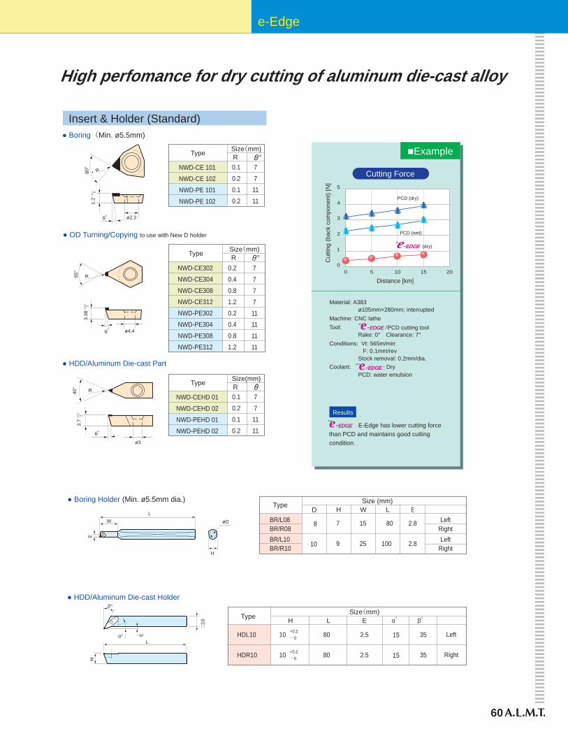
60
e-Edge
High perfomance for dry cutting of aluminum die-cast alloy
Results
Material: A383 ø105mm×280mm; interrupted Machine: CNC latheTool: Rake: 0° Clearance: 7°Conditions: Vt: 565m/min F: 0.1mm/rev Stock removal: 0.2mm/dia.Coolant: e-EDGE : Dry PCD: water emulsion
Insert & Holder (Standard)
● Boring Holder (Min. ø5.5mm dia.)
■Example
e-EDGE E-Edge has lower cutting forcethan PCD and maintains good cuttingcondition.
0 5 10 15 200
1
4
3
2
5
Cut
ting
(bac
k co
mpo
nent
) [N
]
Distance [km]
PCD (dry)
PCD (wet)
TypeEH W L
Size (mm)
BR/L08BR/R08BR/L10BR/R10
7
9
15
25
80
100
2.8
2.8
(dry)
L
H
W
E
● HDD/Aluminum Die-cast Holder
HDL10
HDR10
10
10
Type
+0.2-0
+0.2-0
2.5
2.5
80
80
Left
Right
35
35
15
15
H L ESize(mm)
α゜ β゜
Eα°
□10
H
L
β°
e-EDGENew D
e-EDGE /PCD cutting toolNew D
New D
New D
Cutting Force
D
8
10
LeftRightLeft
Right
øD
● OD Turning/Copying to use with New D holder
NWD-CE302
NWD-CE304
NWD-CE308
NWD-CE312
NWD-PE302
NWD-PE304
NWD-PE308
NWD-PE312
0.2
0.4
0.8
1.2
0.2
0.4
0.8
1.2
7
7
7
7
11
11
11
11
Type
● HDD/Aluminum Die-cast Part
NWD-CEHD 01
NWD-CEHD 02
NWD-PEHD 01
NWD-PEHD 02
0.1
0.2
0.1
0.2
7
7
11
11
Size(mm)R °
Type Size(mm)R ゜R40
°
ø3
R
3.38
+0.
2
3.7+
0.2 0
ø4.4
55°
0
● Boring (Min. ø5.5mm)
NWD-CE 101
NWD-CE 102
NWD-PE 101
NWD-PE 102
0.1
0.2
0.1
0.2
7
7
11
11
Type Size(mm)R °
ø2.3
R80°
1.2+
0.1 0
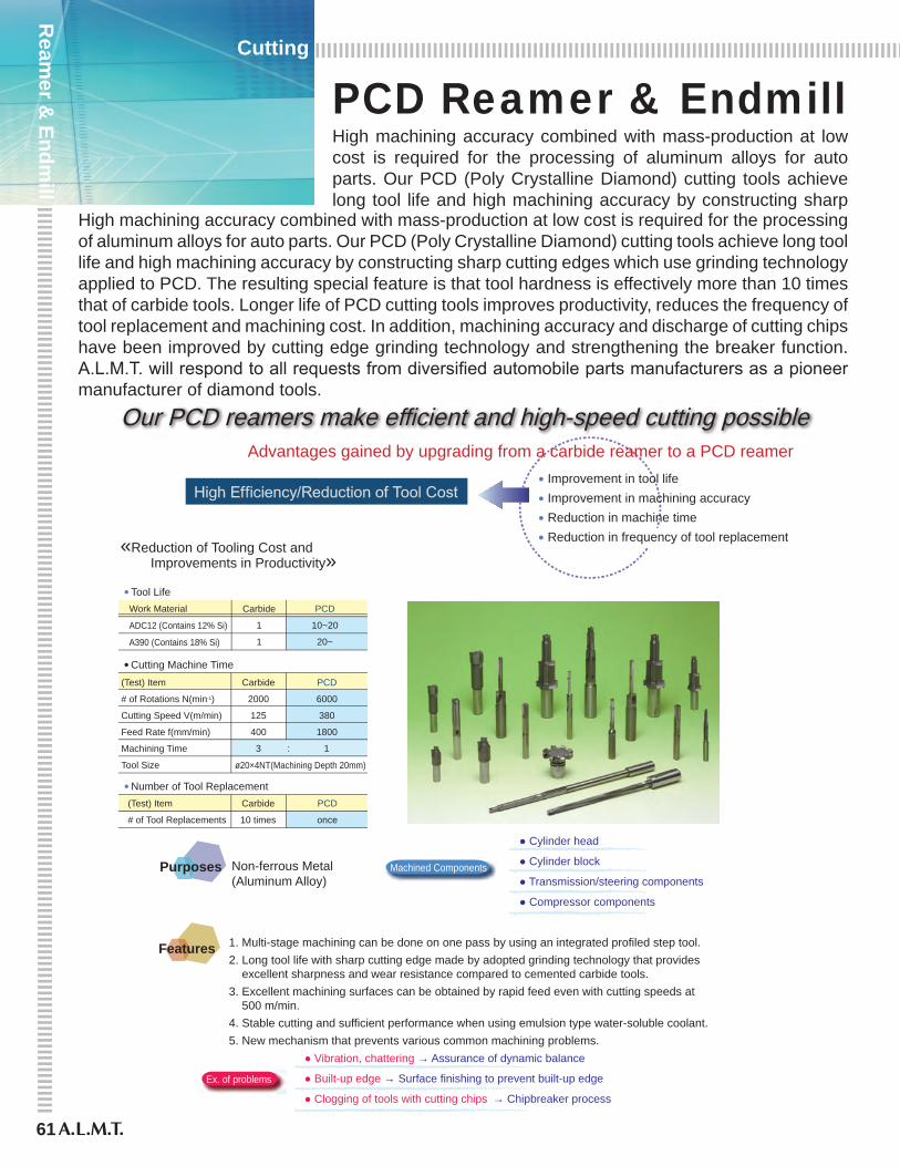
61
Ream
er & Endm
ill
Cutting
PCD Reamer & EndmillHigh machining accuracy combined with mass-production at low cost is required for the processing of aluminum alloys for auto parts. Our PCD (Poly Crystalline Diamond) cutting tools achieve long tool life and high machining accuracy by constructing sharp
High machining accuracy combined with mass-production at low cost is required for the processing of aluminum alloys for auto parts. Our PCD (Poly Crystalline Diamond) cutting tools achieve long tool life and high machining accuracy by constructing sharp cutting edges which use grinding technology applied to PCD. The resulting special feature is that tool hardness is effectively more than 10 times that of carbide tools. Longer life of PCD cutting tools improves productivity, reduces the frequency of tool replacement and machining cost. In addition, machining accuracy and discharge of cutting chips have been improved by cutting edge grinding technology and strengthening the breaker function. A.L.M.T. will respond to all requests from diversified automobile parts manufacturers as a pioneer manufacturer of diamond tools.
Work Material
ADC12 (Contains 12% Si)
A390 (Contains 18% Si)
Carbide
2000
125
400
Carbide
1
1
PCD
10~20
20~
PCD
6000
380
1800
(Test) Item
# of Tool Replacements
Carbide
10 times
PCD
once
3 : 1
ø20×4NT(Machining Depth 20mm)
● Cutting Machine Time
● Number of Tool Replacement
(Test) Item
# of Rotations N(min-1)
Cutting Speed V(m/min)
Feed Rate f(mm/min)
Machining Time
Tool Size
«Reduction of Tooling Cost and Improvements in Productivity»
Our PCD reamers make efficient and high-speed cutting possible
● Tool Life
Advantages gained by upgrading from a carbide reamer to a PCD reamer● Improvement in tool life● Improvement in machining accuracy● Reduction in machine time● Reduction in frequency of tool replacement
Non-ferrous Metal(Aluminum Alloy)
● Cylinder head
● Cylinder block
● Transmission/steering components
● Compressor components
Features
Purposes
● Vibration, chattering → Assurance of dynamic balance
● Built-up edge → Surface finishing to prevent built-up edge
● Clogging of tools with cutting chips → Chipbreaker process
1. Multi-stage machining can be done on one pass by using an integrated profiled step tool. 2. Long tool life with sharp cutting edge made by adopted grinding technology that provides excellent sharpness and wear resistance compared to cemented carbide tools. 3. Excellent machining surfaces can be obtained by rapid feed even with cutting speeds at 500 m/min. 4. Stable cutting and sufficient performance when using emulsion type water-soluble coolant. 5. New mechanism that prevents various common machining problems.
Ex. of problems
Machined Components
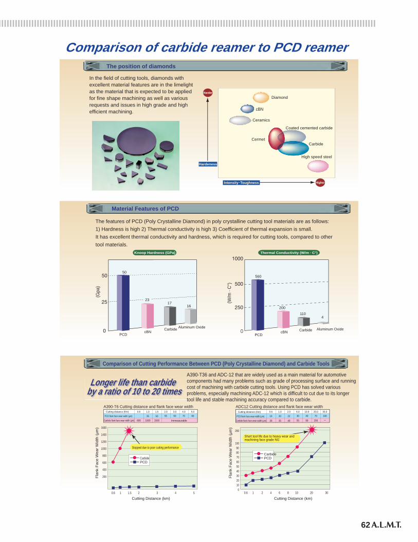
62
Ream
er & Endm
ill
Cutting
In the field of cutting tools, diamonds withexcellent material features are in the limelightas the material that is expected to be appliedfor fine shape machining as well as variousrequests and issues in high grade and highefficient machining.
Diamond
cBN
Ceramics
Coated cemented carbide
Carbide
High speed steel
Cermet
Harder
Higher
Hardeness
Intensity・Toughness
The position of diamonds
(W/m
· C°
)
560
200110
4
Knoop Hardness (GPa) Thermal Conductivity (W/m · C°)
The features of PCD (Poly Crystalline Diamond) in poly crystalline cutting tool materials are as follows:1) Hardness is high 2) Thermal conductivity is high 3) Coefficient of thermal expansion is small.It has excellent thermal conductivity and hardness, which is required for cutting tools, compared to othertool materials.
(Gpa
)
17
cBN cBNCarbide Carbide
Aluminum Oxide Aluminum OxidePCD PCD
Material Features of PCD
50
16
Longer life than carbide by a ratio of 10 to 20 times
Comparison of Cutting Performance Between PCD (Poly Crystalline Diamond) and Carbide Tools
A390-T6 Cutting distance and flank face wear width
60035
100050
1500 Immeasurable
55 60 70 80
A390-T36 and ADC-12 that are widely used as a main material for automotivecomponents had many problems such as grade of processing surface and runningcost of machining with carbide cutting tools. Using PCD has solved variousproblems, especially machining ADC-12 which is difficult to cut due to its longertool life and stable machining accuracy compared to carbide.
Cutting Distance (km)
Flan
k Fa
ce W
ear W
idth
(μm
) 1600
1400
1200
1000
800
600
400
200
0.6 1 1.5 2 3 4 5
Stopped due to poor cutting performance
CarbidePCD
Cutting Distance (km)
Flan
k Fa
ce W
ear W
idth
(μm
)
200
9080
100
70605040302010
00.6 1 2 4 6 8 10 20 30
Short tool life due to heavy wear andmachining face grade NG
CarbidePCD
0.6 1.0 1.5 2.0 3.0 4.0 5.0
ADC12 Cutting distance and flank face wear width
PCD flank face wear width (μm)
Cutting distance (Km)
Carbide flank face wear width (μm)10 20 22 30 40 70 100
30 35 40 55 90 200 ー
0.6 1.0 2.0 6.0 10.0 20.0 30.0
23
Comparison of carbide reamer to PCD reamer
PCD flank face wear width (μm)
Cutting distance (Km)
Carbide flank face wear width (μm)
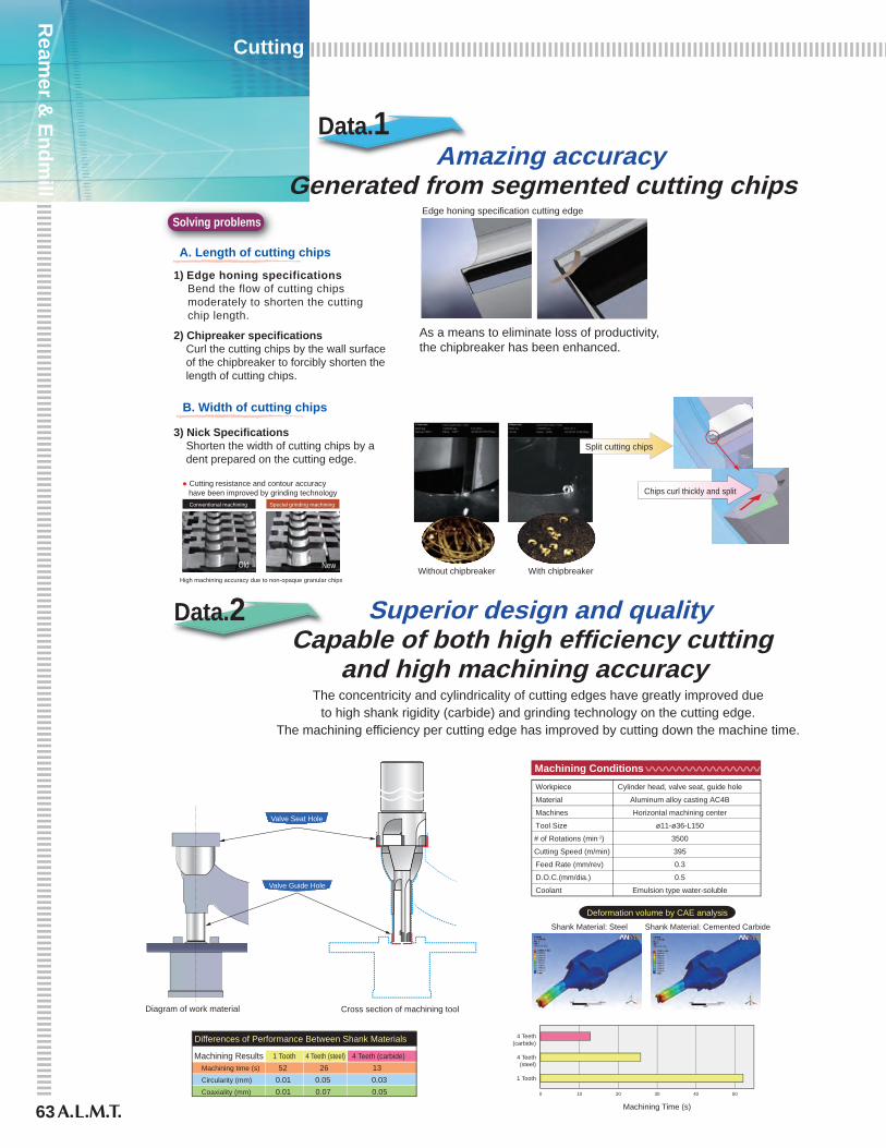
63
Ream
er & Endm
ill
Cutting
1 Tooth 4 Teeth (steel) 4 Teeth (carbide)Machining time (s) 52 26 13Circularity (mm) 0.01 0.05 0.03Coaxiality (mm) 0.01 0.07 0.05
Data.1
Data.2
As a means to eliminate loss of productivity,the chipbreaker has been enhanced.
The concentricity and cylindricality of cutting edges have greatly improved dueto high shank rigidity (carbide) and grinding technology on the cutting edge.
The machining efficiency per cutting edge has improved by cutting down the machine time.
Amazing accuracyGenerated from segmented cutting chips
Workpiece Cylinder head, valve seat, guide hole
Material Aluminum alloy casting AC4B
Machines Horizontal machining center
Tool Size ø11-ø36-L150
# of Rotations (min-1) 3500
Cutting Speed (m/min) 395
Feed Rate (mm/rev) 0.3
D.O.C.(mm/dia.) 0.5
Coolant Emulsion type water-soluble
Machining Conditions
Deformation volume by CAE analysisShank Material: Cemented CarbideShank Material: Steel
Machining Results
1 Tooth
4 Teeth(steel)
4 Teeth(carbide)
0 10 20 30 40 50
Machining Time (s)
Special grinding machiningConventional machining
NewOld ブレーカー有りブレーカー無し
High machining accuracy due to non-opaque granular chips
Chips curl thickly and split● Cutting resistance and contour accuracy have been improved by grinding technology
Edge honing specification cutting edge
1) Edge honing specifications Bend the flow of cutting chips moderately to shorten the cutting chip length.
2) Chipreaker specifications Curl the cutting chips by the wall surface of the chipbreaker to forcibly shorten the length of cutting chips.
3) Nick Specifications Shorten the width of cutting chips by a dent prepared on the cutting edge.
Solving problems
Differences of Performance Between Shank Materials
Diagram of work material Cross section of machining tool
Valve Seat Hole
Valve Guide Hole
A. Length of cutting chips
Split cutting chips
B. Width of cutting chips
Without chipbreaker With chipbreaker
Superior design and qualityCapable of both high efficiency cutting
and high machining accuracy

64
Ream
er & Endm
ill
Cutting
Intake & exhaust valve guide hole finishing
Valve seat and guide hole
HLA (Hydraulic Lash) adjuster hole finishing
Valve seat and guide hole finishing
The issues such as concentricity and cylindricality are solved by high shank rigidityand high cutting edge accuracy.
Intake & exhaust valve guide hole finishing
Concentricity and cylindricality of the cutting edge are controlled by its high accuracyand the self-guide effect is enhanced in order to respond to long overhang and bending.Moreover, the discharge amount of chips by the guide hole shape and coolant design.As a result, it can machine 10 times the number of holes compared to cementedcarbide to improve productivity.
Hydraulic lash adjuster hole finishing
The issues such as chip removal and cylindricality are solved by the designthat responded to thin-walled & blind hole machining portions.
■ Valve seat and guide hole finishing specifications
Machine: Horizontal machining center
MachiningConditions
6,0000.48
2,8800.6
Emulsion type water-soluble
■ Hydraulic lash adjuster hole finishing specifications
MachiningConditions
5,0000.34
1,5400.5
Emulsion type water-soluble
■ Intake & exhaust valve guide hole finishing specifications
■ Machining Results
Machine: Horizontal machining center
MachiningConditions
# of Rotations (min-1)Feed Rate (mm/rev)Feed Speed (mm/min)D.O.C. (mm/dia)Coolant
3,2500.1
3250.1
Emulsion type water-soluble
Cutting ToolCarbide
Our PCD tool
Tool Life(# machined holes)
1,200 1 1 — —
12,000 3 0.8 10μm 3μm/10,000 hole
Machining Application
# of Rotations (min-1)Feed Rate (mm/rev)Feed Speed (mm/min)D.O.C. (mm/dia)Coolant
Machine: Horizontal machining center
# of Rotations (min-1)Feed Rate (mm/rev)Feed Speed (mm/min)D.O.C. (mm/dia)Coolant
Ratioof prices
Ratioof costs Coaxiality Inner diameter change volume
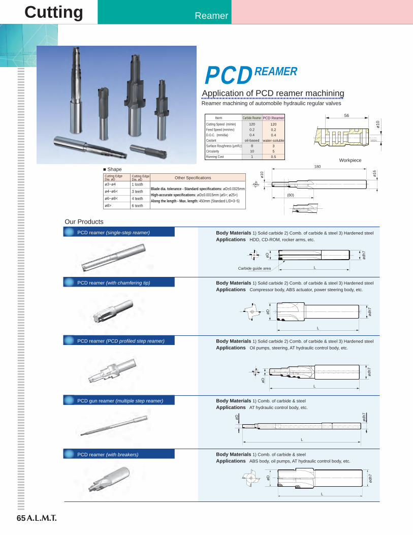
65
Cutting Reamer
Carbide guide areaøD
ø10
ø10
ø16
L
ødh7
øD
L
ødh7
PCD reamer (with chamfering tip)
PCD reamer (PCD profiled step reamer)
PCD gun reamer (multiple step reamer)
PCD reamer (with breakers)
PCD reamer (single-step reamer)
øD
L
ødh7
øD
øD
L
ødh7
ødh7
L
Body Materials 1) Solid carbide 2) Comb. of carbide & steel 3) Hardened steelApplications HDD, CD-ROM, rocker arms, etc.
Body Materials 1) Solid carbide 2) Comb. of carbide & steel 3) Hardened steelApplications Compressor body, ABS actuator, power steering body, etc.
Body Materials 1) Solid carbide 2) Comb. of carbide & steel 3) Hardened steelApplications Oil pumps, steering, AT hydraulic control body, etc.
Body Materials 1) Comb. of carbide & steelApplications AT hydraulic control body, etc.
Body Materials 1) Comb. of carbide & steelApplications ABS body, oil pumps, AT hydraulic control body, etc.
Our Products
Cutting EdgeDia. øDø3~ø4
ø4~ø6<
ø6~ø8<
ø8>
Cutting EdgeDia. øD1 tooth
3 teeth
4 teeth
6 teeth
Blade dia. tolerance - Standard specifications: øD±0.0025mmHigh-accurate specifications: øD±0.0015mm (ø5>; ø25>)Along the length - Max. length: 450mm (Standard L/D=3~5)
Other Specifications
■ Shape
Reamer machining of automobile hydraulic regular valvesApplication of PCD reamer machining
Carbide Reamer
1200.20.4
oil-based8101
PCD Reamer
1200.20.4
water-soluble35
0.5
Cutting Speed (m/min)Feed Speed (mm/rev)D.O.C. (mm/dia)CoolantSurface Roughness (μmRz)CircularityRunning Cost
Item
180
56
(80)
PCDREAMER
Workpiece
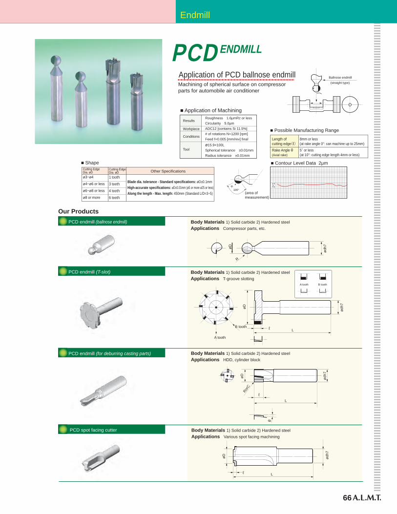
66
Endmill
PCDENDMILL
PCD endmill (ballnose endmill)
PCD endmill (T-slot)
PCD endmill (for deburring casting parts)
PCD spot facing cutter
Our Products
Blade dia. tolerance - Standard specifications: øD±0.1mmHigh-accurate specifications: øD±0.01mm (ø5 or more ø25 or less)Along the length - Max. length: 450mm (Standard L/D=3~5)
Other Specifications
■ Shape
Length ofcutting edge(ℓ)Rake Angle θ(Axial rake)
8mm or less(at rake angle 0°: can machine up to 25mm)5° or less(at 10°: cutting edge length 4mm or less)
■ Possible Manufacturing Range
øD
R
ødh7
Body Materials 1) Solid carbide 2) Hardened steelApplications Compressor parts, etc.
(area ofmeasurement)
100°
Results
Workpiece
Conditions
Tool
Roughness 1.6μmRz or lessCircularity 5.0μmADC12 [contains Si 11.5%]# of rotations N=1200 [rpm]Feed f=0.005 [mm/rev] final
ø15.9×100LSpherical tolerance ±0.01mmRadius tolerance ±0.01mm
■ Application of Machining
Ballnose endmill
(straight type)
ødh7
øD
L
Body Materials 1) Solid carbide 2) Hardened steelApplications Various spot facing machining
ℓ
B tooth
A tooth
øD
L
ødh7
Body Materials 1) Solid carbide 2) Hardened steelApplications T-groove slotting
B toothA tooth
ℓ
øD
L
ødh7
RorC
Body Materials 1) Solid carbide 2) Hardened steelApplications HDD, cylinder block
θ
ℓ
Machining of spherical surface on compressorparts for automobile air conditioner
Application of PCD ballnose endmill
■ Contour Level Data 2μmCutting EdgeDia. øDø3~ø4
ø4~ø6 or less
ø6~ø8 or less
ø8 or more
Cutting EdgeDia. øD1 tooth
3 teeth
4 teeth
6 teeth
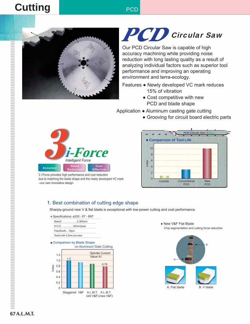
67
Cutting PCD
NoiseReduction
CostEffective
Sharply-ground new V & flat blade is exceptional with low-power cutting and cost performance
Speed ………………2,365rpm
D.O.C. ………… 30mm/pass
Feed/tooth…19μm
Tested with 0.2mm pre-wear
0
2
4
6
8
10
Carbide ConventionalPCD
NewPCD
Inde
x
Spindle CurrentValue(A)
1.0
0
0.2
0.4
0.6
0.8
1.0
1.2
0.78
V&FStaggered A.L.M.T.(old V&F)
A.L.M.T.(new V&F)
■ Comparison by Blade Shape on Aluminum Gate Cutting
■ Comparison of Tool Life
● Specifications: ø250 - 6T - 8NT
i-ForcePCD Circular Saw 3i-Force
Intelligent Force
● New V&F Flat BladeChip segmentation and cutting force reduction
B. V blade
B
A. Flat blade
A
1. Best combination of cutting edge shape
Our PCD Circular Saw is capable of high accuracy machining while providing noise reduction with long lasting quality as a result of analyzing individual factors such as superior tool performance and improving an operating environment and terra-ecology.Features ● Newly developed VC mark reduces 15% of vibration ● Cost competitive with new PCD and blade shape
Application ● Aluminum casting gate cutting ● Grooving for circuit board electric parts
3 i-Force provides high performance and cost reductiondue to matching the blade shape and the newly developed VC mark--our own innovative design.
Circular Saw
Accuracy
Inde
x

68
Circular Saw
Z
Y
X
105
100
95
90
85
80
75
Noi
se V
alue
(dB
)
No Mark OldVC Mark
NewVC Mark
101
85
92
New VC mark was developed by using 3-dimensional CAE analysis and a testmodel trial.New VC mark suppresses cutting vibration max. 15% and provides a comfortableoperationg environment.
Waved form chart shows damping effect by type. Newly developed VC mark provides high accracy cutting while reducingchipping of cutting edge.
NoMark
OldVC Mark
NewVC Mark
→ Time
Am
plitu
de
2. Damping effect by newly developed VC markDATADATA
Max. principle stress (with slit)
Max. principle stress (without slit)
1) Release internal stains and reduce side run-out2) Dissipate cutting heat and protect tip brazing
Prevent deformation and tip elimination by cutting heat
Thinner cutters are required for chips and power reduction according to Green Procurement on ISO14000s.Special attention to detail has resulted in the succesful development ofthe slit, which reduces stress and cuts heat.
3. 2 effects by unique slit shape
DATA
■ Comparison of Dampened Wave
→
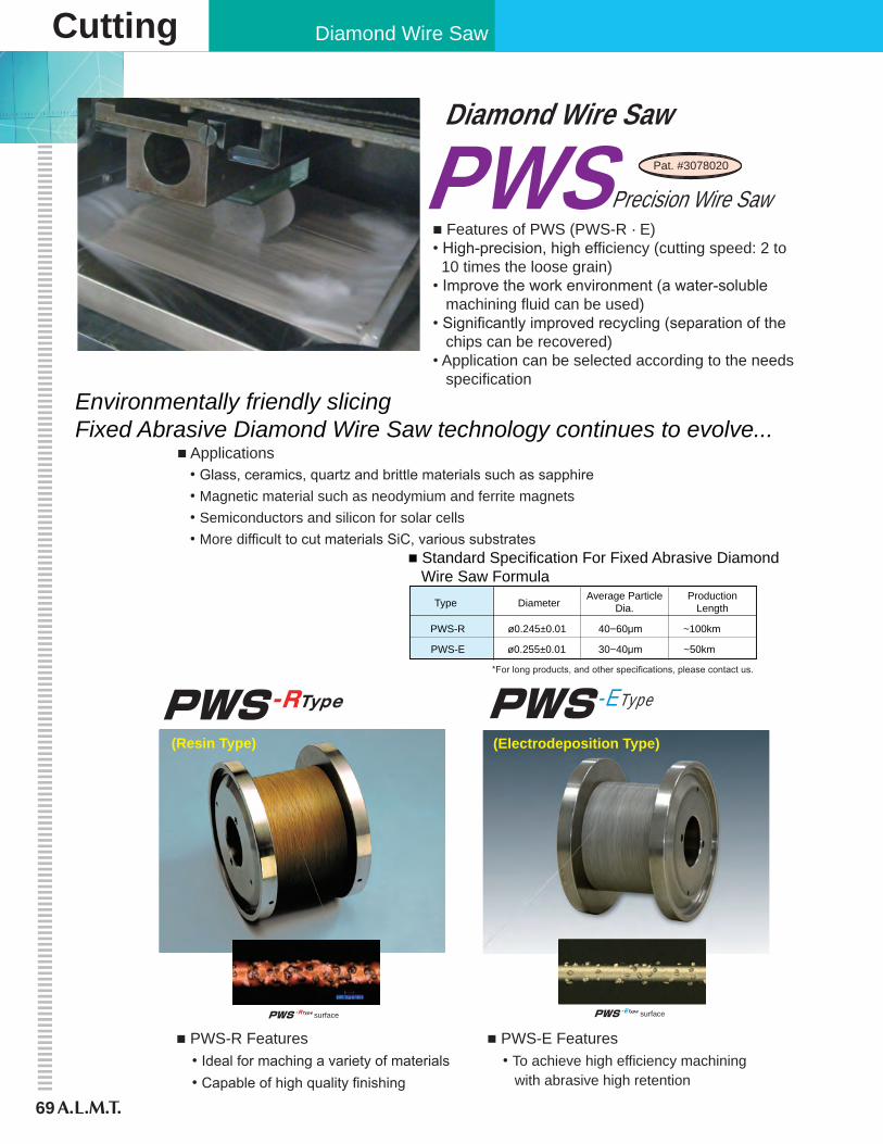
69
Cutting Diamond Wire Saw
-RType -EType
-EType surface
(Electrodeposition Type)
-RType surface
(Resin Type)
Diamond Wire SawPat. #3078020PWSPrecision Wire Saw
■ Standard Specification For Fixed Abrasive Diamond Wire Saw Formula
Type DiameterAverage Particle
Dia.Production
Length
PWS-R ø0.245±0.01 40−60μm ~100km
PWS-E ø0.255±0.01 30−40μm ~50km
■ Features of PWS (PWS-R · E)• High-precision, high efficiency (cutting speed: 2 to 10 times the loose grain) • Improve the work environment (a water-soluble machining fluid can be used)• Significantly improved recycling (separation of the chips can be recovered) • Application can be selected according to the needs specification
■ Applications• Glass, ceramics, quartz and brittle materials such as sapphire • Magnetic material such as neodymium and ferrite magnets • Semiconductors and silicon for solar cells • More difficult to cut materials SiC, various substrates
■ PWS-R Features• Ideal for maching a variety of materials• Capable of high quality finishing
■ PWS-E Features• To achieve high efficiency machining with abrasive high retention
*For long products, and other specifications, please contact us.
Environmentally friendly slicingFixed Abrasive Diamond Wire Saw technology continues to evolve...
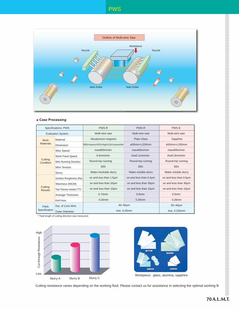
70
PWS
Workpiece: glass, alumina, sapphire
High
Low
Cut
-thro
ugh
Res
ista
nce
Slurry A Slurry CSlurry B
WorkpieceNozzleNozzle
Outline of Multi-wire Saw
Main Roller Main Roller
Evaluation System
Specifications: PWS PWS-R PWS-R PWS-E
Multi-wire saw Multi-wire saw Multi-wire saw
WorkMaterials
CuttingCondition
Cutting Results
■ Case Processing
* Total length of cutting direction was measured.
Material
Dimension
Wire Speed
Work Feed Speed
Wire Running Direction
Wire Tension
Slurry
Surface Roughness (Ra)
Waviness (WCM)
Total Thickness Variation(TTV)
Average Thickness
Kerf-loss
Dia. of Core Wire
Outer Diameter
PWSSpecification
Plate Glass
ø50mm×L200mm
max400m/min
Ave0.1mm/min
Round-trip running
35N
Water-soluble slurry
on and less than 0.4μm
on and less than 30μm
on and less than 10μm
0.6mm
0.26mm
40−60μm
Ave. 0.25mm
Neodymium magnets
W(50×4columns)×H(25×4high)×L(50×2columns)mm
max800m/min
0.6mm/min
Round-trip running
30N
Water-insoluble slurry
on and less than 1.5μm
on and less than 20μm
on and less than 10μm
0.74mm
0.26mm
Sapphire
ø50mm×L200mm
max400m/min
Ave0.3mm/min
Round-trip running
35N
Water-soluble slurry
on and less than 0.5μm
on and less than 30μm
on and less than 10μm
0.6mm
0.26mm
30−40μm
Ave. 0.255mm
Cutting resistance varies depending on the working fluid. Please contact us for assistance in selecting the optimal working fluid.

71
CPG
& O
DIU
P
Other Products
High Operativity and High Output
■ Specifications● ø150mm projector● Constant feed unit● Coolant unit● Holder (QC-21)
● CPG-310Linear scale (min. 1µm)
● CPG-200Ball screw and length measuring encoder
■ Options Special power-up units for CPG Series
Angle measuring encoder(min. 1 min.)
Paper filler type
■ Accessories
Special jigs for CPG series
● Brake trueing unit BT-2 ● 3-D vise ● On machine dressing CT-1(CPG-310)
● Jig for radius grinding ● Jig for negative land
● Jig for cylindrical grinding● Holders
1) Incomparable rigidityPrecise angler bearing for grinding spindleand pivot
2) Excellent grind accuracySuper rigid grinding spindle for sharp cutting edge grinding
3) Highly efficient operationQuick cutting edge angle and relief angle with oscillating location adjustment of wheel with workpiece sight. Leaning mechanics with centering grinding point and highly precise projector for high efficiency operating environment.
■ Features
For Carbide Tool GrindingCPG Series Compact Tool Grinders
・
● Basic grinder for low volume production● X20 projector for centering and profiling
● Constant feed and handwheel operated oscillating width control.
● X20 projector for centering and profiling.
Depth Feed Digital Meter Angle Digital Meter Coolant Tank
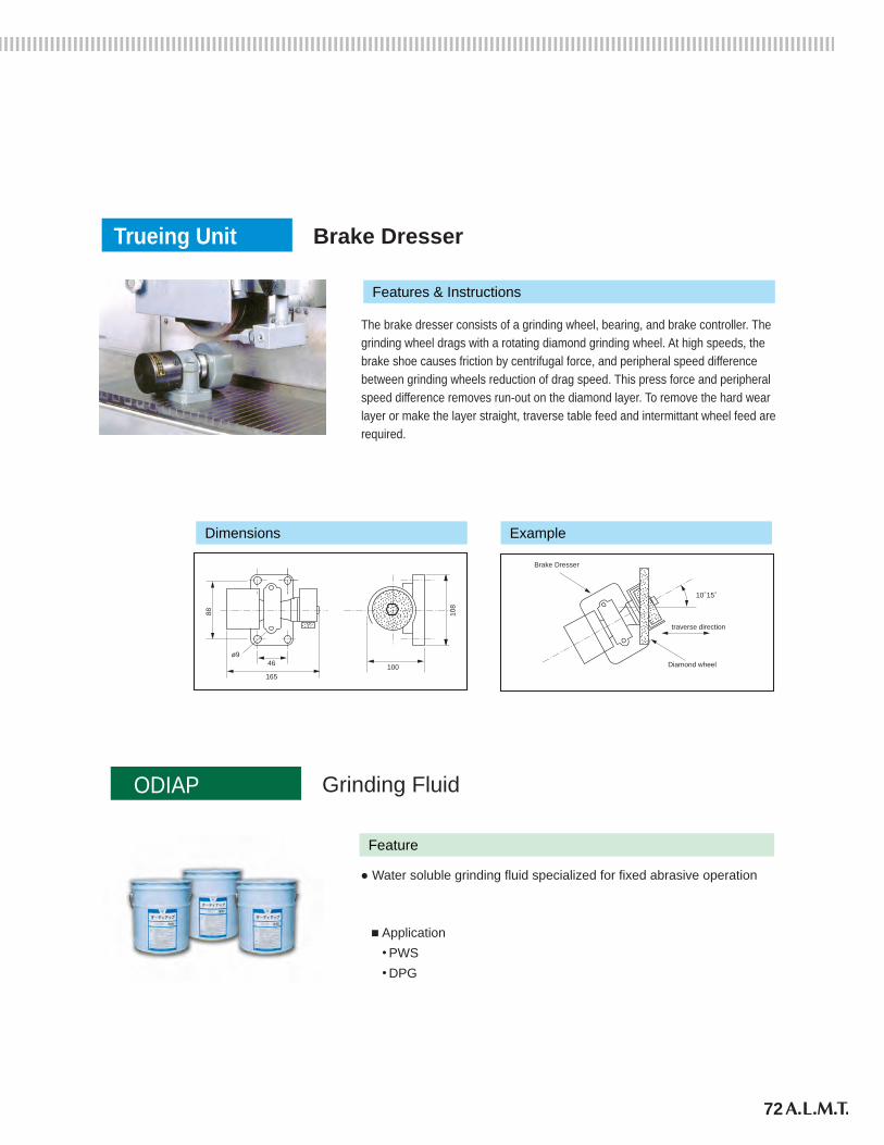
72
Brake DresserTrueing Unit
Grinding Fluid
The brake dresser consists of a grinding wheel, bearing, and brake controller. Thegrinding wheel drags with a rotating diamond grinding wheel. At high speeds, thebrake shoe causes friction by centrifugal force, and peripheral speed differencebetween grinding wheels reduction of drag speed. This press force and peripheralspeed difference removes run-out on the diamond layer. To remove the hard wearlayer or make the layer straight, traverse table feed and intermittant wheel feed arerequired.
Dimensions Example
Features & Instructions
ø9
88
46
165100
traverse direction
Diamond wheel
Brake Dresser
108
10°15°
ODIAP
● Water soluble grinding fluid specialized for fixed abrasive operation
Feature
■ Application ● PWS ● DPG
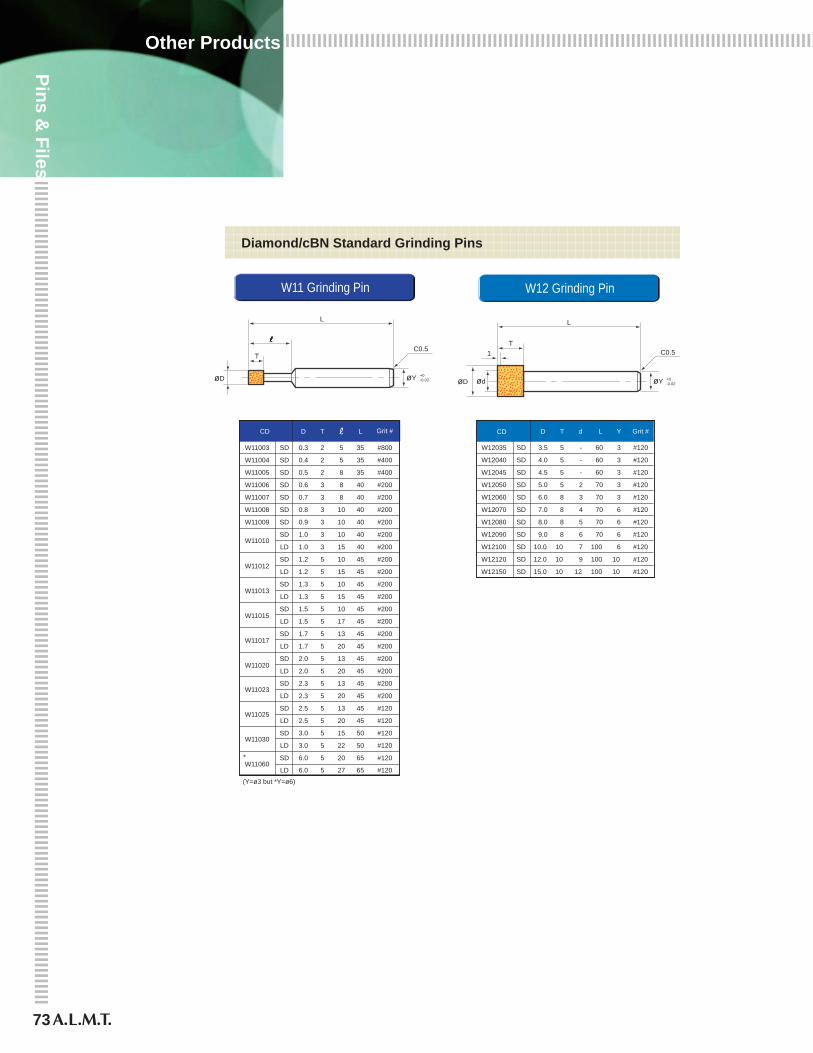
73
Pins & Files
Other Products
CD D T Yd Grit #
W12035 SD 3.5 5 - 3 #120
W12040 SD 4.0 5 - 3 #120
W12045 SD 4.5 5 - 3 #120
W12050 SD 5.0 5 2 3 #120
W12060 SD 6.0 8 3 3 #120
W12070 SD 7.0 8 4 6 #120
W12080 SD 8.0 8 5 6 #120
W12090 SD 9.0 8 6 6 #120
W12100 SD 10.0 10 7 6 #120
W12120 SD 12.0 10 9 10 #120
W12150 SD 15.0 10 12
L
60
60
60
70
70
70
70
70
100
100
100 10 #120
CD D T L Grit #
W11003 SD 0.3 2 5 35 #800
W11004 SD 0.4 2 5 35 #400
W11005 SD 0.5 2 8 35 #400
W11006 SD 0.6 3 8 40 #200
W11007 SD 0.7 3 8 40 #200
W11008 SD 0.8 3 10 40 #200
W11009 SD 0.9 3 10 40 #200
W11010SD 1.0 3 10 40 #200
LD 1.0 3 15 40 #200
W11012SD 1.2 5 10 45 #200
LD 1.2 5 15 45 #200
W11013SD 1.3 5 10 45 #200
LD 1.3 5 15 45 #200
W11015SD 1.5 5 10 45 #200
LD 1.5 5 17 45 #200
W11017SD 1.7 5 13 45 #200
LD 1.7 5 20 45 #200
W11020SD 2.0 5 13 45 #200
LD 2.0 5 20 45 #200
W11023SD 2.3 5 13 45 #200
LD 2.3 5 20 45 #200
W11025SD 2.5 5 13 45 #120
LD 2.5 5 20 45 #120
W11030SD 3.0 5 15 50 #120
LD 3.0 5 22 50 #120
LD 6.0 5 27 65 #120W11060
SD 6.0 5 20 65 #120*
W11 Grinding Pin W12 Grinding Pin
Diamond/cBN Standard Grinding Pins
L
C0.5T
+0-0.02øY
L
C0.5T
1
+0-0.02øDøD ød øY
(Y=ø3 but *Y=ø6)
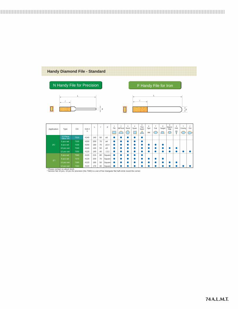
74
CD Grit #G
L
#140 140 50
7320 #200 200 70
7330 #200 180 70
7340 #140 140 50
7350 #120 140 40
7360 #120 215 80
7370 #120 200 70
7380 #120 185 50
7390 #120 170 40
Type
5 pcs set
8 pcs set
10 pcs set
12 pcs set
5 pcs set
8 pcs set
10 pcs set
12 pcs set
Application
(N)
(F)
d
ø3
ø4
ø3.4
ø3
□2.2
Square
Square
Square
Square
1Flat
2Half Round
3Round
4Square
5Three
Square6
Taper7
Oval8
Swaged9
BalanceEdge
XKnife
YCrossing
Z Clam
N Handy File for Precision F Handy File for Iron
Handy Diamond File - Standard
L
d
L
d
731010 Piecevalue set
* Please contact us about stock. * Service Set 10 pcs, 10 pcs for precision (No.7340) is a set of five triangular flat half-circle round the corner.

The application field of diamond and cBN tools is very wideand diversified, and the demand on the tools is also severe and wide-ranged in accuracy, efficiency, tool life, and environmentalconcerns. In order to meet demands, A.L.M.T. Corp. establishedthe Customer Technical Center as a solution center to assist andsupport customers. The CTC is composed of three sections: 1) platform, 2) process evaluation, including measurement and inspection, and 3) presentation and meeting room.
CTC supports our customers’ engineering development
Platform
ProcessingPresentation & MeetingRoom
Realizing customer satisfaction
The products and technologies developed by A.L.M.T. Corp. are illustrated (left).There are 4 sectors: Cutting, Grinding, Polishing, and Forming. New and flexiblesolutions to diversified requests, plus information to make conclusions regardingfuture related issues.
The issues at hand are: environment, increase in productivity, cost reduction,number of requests that require quality improvement, and discussion andtechnical issues; problem solving is a measure of success.
Leading-edge processing can only be achieved with up-to-date machines.In this sector, the leading machines installed are classified into three groups:1) high efficiency processing, 2) wire slicing with bonded wire saw, and3) precision processing. In each grouping, tools and work to be processed aretried and evaluated on the spot with installed measurement equipment.
Operation and Evaluation
Lay out technologies in four themes
Shape a theme through verification and discovery
Order trialevaluation
TechnicalconsultationReport
trialresult
Quotefortrial
operatrion
Tool &techniques
info
Customer
Products and technologiesdeveloped from basictechnologies
Exploring new technologies
From Inquiry to Report
Platform
Technical database though production and measurement
75
Information
CTC
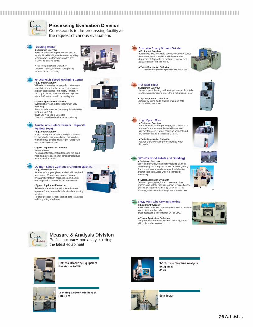
76
Processing Evaluation DivisionCorresponds to the processing facility atthe request of various evaluations
NC High Speed Cylindrical Grinding Machine ■ Equipment OverviewUltrafast NC's largest cylindrical wheel with peripheralspeed up to 160m/sec. as a grinder. Plunge offerrous material at high peripheral speed, Kontariswitching conduct the search, can be evaluated.
■ Typical Application EvaluationHigh peripheral speed and cylindrical grinding toimprove efficiency on iron-based materials processingwork test For the purpose of reducing the high peripheral speedand the grinding wheel wear.
Vertical High Speed Machining Center ■ Equipment OverviewWith axial core cooling, its unique lubrication underrace lubrication hollow ball screw cooling systemand high-speed spindle, high rigidity 50m/min. inthe body structure, high capacity due to high feedrate of 0.6G has achieved a processing rate.
■ Typical Application Evaluation CVD tool life evaluation tests in aluminum alloymachining New composite materials processing characterizationusing test tools PSL*CVD: Chemical Vapor Deposition(Diamond coated by chemical vapor synthesis)
Grinding Center■ Equipment Overview Based on the machining center manufacturedby Hitachi Seiki VK55; was developed by addingsearch capabilities to machining is the bestmachine for grinding center.
■ Typical Applications EvaluationCeramics, carbide, hardened steel grinding,complex action processing
HighEfficiency
Precision Slicer ■ Equipment OverviewUltra-precision air bearings with static pressure on the spindle,small and accurate feeding makes this a high precision slicer.
■ Typical Application Evaluation Ceramics by slicing blade, stacked evaluation tests,such as slicing condenser
Precision Rotary Surface Grinder■ Equipment OverviewBuilt-in motor type air spindle is precisie with water-cooledheat to enable smooth rotation with little vibrationdisplacement. Applied to the evaluation process, suchas a silicon wafer with fine wheel.
■ Typical Application Evaluation ・Silicon wafer processing such as fine wheel test.
Double-axis Surface Grinder - Opposite(Vertical Type)■ Equipment OverviewTo pass through the axis of the workpiece betweenthe two wheels facing up and down by immediatevertical surface grinding. Has a highly rigid spindleheld by the prismatic slide.
■ Typical Applications EvaluationFerrous sintered Processing of mechanical parts such as two-sided machining castings efficiency, dimensional surfaceaccuracy evaluation test
Measure & Analysis DivisionProfile, accuracy, and analysis usingthe latest equipment
3-D Surface Structure AnalysisEquipmentZYGO
Flatness Measuring Equipment Flat Master 200XR
Scanning Electron MicroscopeEDX-SEM Spin Tester
PWS Multi-wire Sawing Machine■ Equipment OverviewFixed abrasive diamond wire saw (PWS) using a multi-wire.A machine for cutting only. Does not require a loose grain as well as DPG.
■ Typical Application Evaluation Sapphire, multi-processing efficiency in cutting, such assilicon, flat trial evaluation.
TVG9
DPG (Diamond Pellets and Grinding) ■ Equipment OverviewBased on technology developed by lapping, diamondpellets rigidity that is required for fixed abrasive grinding.The process by wrapping loose grain, fixed abrasivegreener can be evaluated when it is changed toprocessing.
■ Typical Application Evaluation Ceramics, quartz, glass, in the conventional planarprocessing of metallic materials to move to high-efficiencygrinding process by DPG from lap when processingefficiency, reach the surface roughness evaluation test
High Speed Slicer ■ Equipment OverviewEquipped with a discharge trueing system, ideally on amachine Tsuru can swing. Evaluated by automaticalignment to speed. S wheel adopts an air spindle andlow-vibration spindle thermal displacement. ■ Typical Application Evaluation Adapted to the evaluation process such as waferthin blade.
HighEfficiency
HighEfficiency
HighEfficiency
HighPrecision
HighPrecision
HighPrecision
GreenMachining
GreenMachining
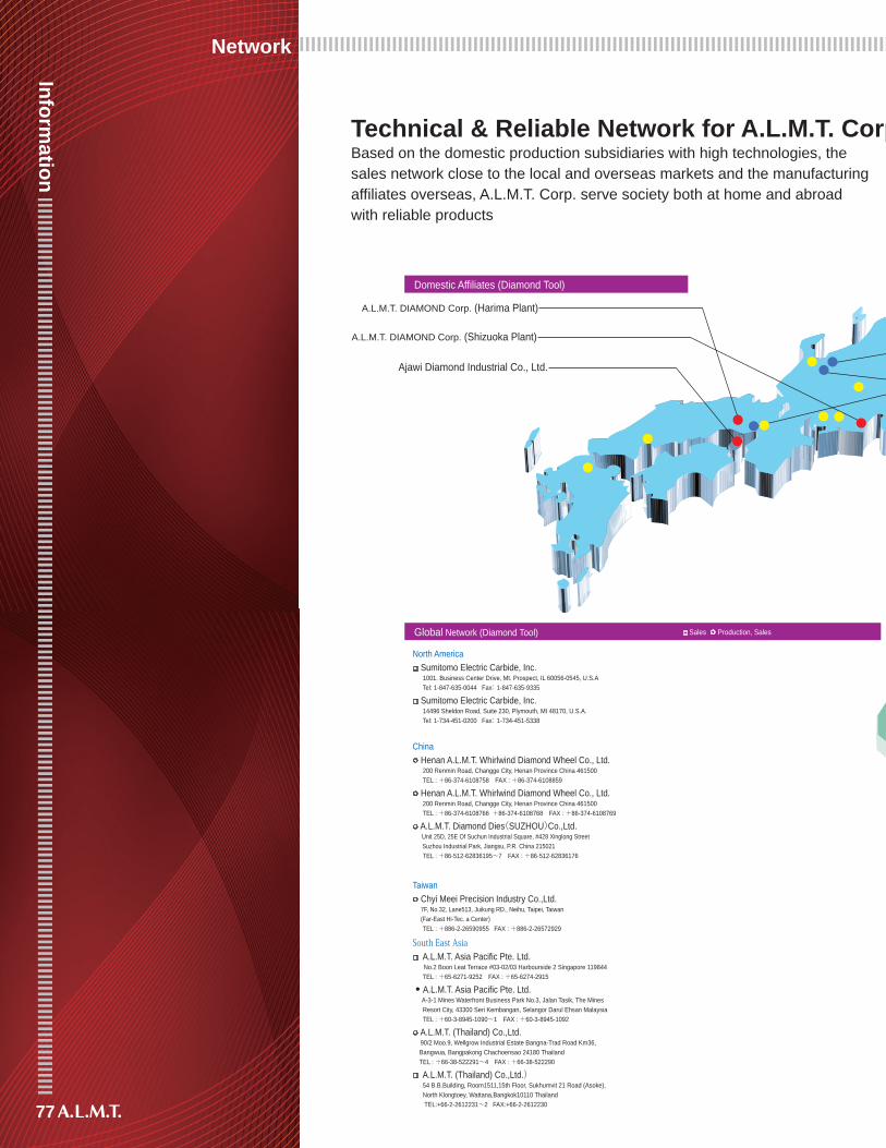
77
Information
Network
A.L.M.T. DIAMOND Corp. (Harima Plant)
A.L.M.T. DIAMOND Corp. (Shizuoka Plant)
Ajawi Diamond Industrial Co., Ltd.
A.L.M.T. TECH Inc. (Sakata Plant) A.L.M.T. TECH Inc. (Toyama Plant)
A.L.M.T. TECH Inc. (Itami Plant)
A.L.M.T. TUNGSTEN Corp. (Toyama Plant)
Based on the domestic production subsidiaries with high technologies, thesales network close to the local and overseas markets and the manufacturing affiliates overseas, A.L.M.T. Corp. serve society both at home and abroadwith reliable products
Global Network (Diamond Tool)
Domestic Affiliates (Diamond Tool) Domestic Affiliates (Functional Material)
North America Sumitomo Electric Carbide, Inc.
1001. Business Center Drive, Mt. Prospect, IL 60056-0545, U.S.A Tel: 1-847-635-0044 Fax: 1-847-635-9335
Sumitomo Electric Carbide, Inc. 14496 Sheldon Road, Suite 230, Plymouth, MI 48170, U.S.A. Tel: 1-734-451-0200 Fax: 1-734-451-5338
China Henan A.L.M.T. Whirlwind Diamond Wheel Co., Ltd.
200 Renmin Road, Changge City, Henan Province China 461500 TEL : +86-374-6108758 FAX : +86-374-6108859
Henan A.L.M.T. Whirlwind Diamond Wheel Co., Ltd. 200 Renmin Road, Changge City, Henan Province China 461500 TEL : +86-374-6108766 +86-374-6108768 FAX : +86-374-6108769
A.L.M.T. Diamond Dies(SUZHOU)Co.,Ltd. Unit 25D, 25E Of Suchun Industrial Square, #428 Xinglong Street Suzhou Industrial Park, Jiangsu, P.R. China 215021 TEL : +86-512-62836195~7 FAX : +86-512-62836176
Taiwan Chyi Meei Precision Industry Co.,Ltd.
7F, No.32, Lane513, Juikung RD., Neihu, Taipei, Taiwan (Far-East Hi-Tec. a Center) TEL : +886-2-26590955 FAX : +886-2-26572929
South East Asia A.L.M.T. Asia Pacific Pte. Ltd. No.2 Boon Leat Terrace #03-02/03 Harbourside 2 Singapore 119844 TEL : +65-6271-9252 FAX : +65-6274-2915
● A.L.M.T. Asia Pacific Pte. Ltd. A-3-1 Mines Waterfront Business Park No.3, Jalan Tasik, The Mines Resort City, 43300 Seri Kembangan, Selangor Darul Ehsan Malaysia TEL : +60-3-8945-1090~1 FAX : +60-3-8945-1092
A.L.M.T. (Thailand) Co.,Ltd. 90/2 Moo.9, Wellgrow Industrial Estate Bangna-Trad Road Km36, Bangwua, Bangpakong Chachoensao 24180 Thailand TEL : +66-38-522291~4 FAX : +66-38-522290
A.L.M.T. (Thailand) Co.,Ltd.) 54 B.B.Building, Room1511,15th Floor, Sukhumvit 21 Road (Asoke), North Klongtoey, Wattana,Bangkok10110 Thailand TEL:+66-2-2612231~2 FAX:+66-2-2612230
Global Network (Functional Material)
Europe Sumitomo Electric Hartmetall GmbH
Siemensring 84, D-47877 Willich, Germany Tel: 49-2154-49920 Fax:49-2154-41072 North America
Sumitomo Electric U.S.A.,INC. 21221 S. Western Avenue, Suite 200 Torrance,California 90501, U.S.A. Tel: 1-310-782-0227 Fax: 1-310-782-0211
China Chengdu Liang Hong Molybdenum Co., Ltd.
No.198 Nanjing Road, Chengdu Economic And Technological Development Zone, Longquanyi District, Chengdu, China TEL : +86-28-88432459 FAX : +86-28-88432456
1-11-11, Shiba, Minato-ku, Tokyo, 105-0014TEL: +81-3-5418-1801 FAX: +81-3-5418-1810URL http://www.allied-material.co.jp/
LaboratoriesDevelopment and Design Department1-1-1, Koyakita, Itami City, Hyogo 664-0016(within Itami Plant of Sumitomo Electric Industries,Ltd. Corporation)
Materials Research Department2, Iwase-Koshi-machi, Toyama City, Toyama 931-8543TEL: +81-76-437-1951 FAX: +81-76-438-9033
Tools Research Department1816-174, Kotaka-Kuroishi, Kato City, Hyogo 679-0221TEL: +81-795-48-1778 FAX: +81-795-48-1779
Sales DepartmentsFunctional Materials Group1-11-11, Shiba, Minato-ku, Tokyo, 105-0014TEL: +81-3-5418-1805 FAX: +81-3-5418-1811
Diamond Tool Group1-11-11, Shiba, Minato-ku, Tokyo, 105-0014TEL: +81-3-5418-1809 FAX: +81-3-5418-1811
Head Office
Sales ○ Production, Sales
Sales ○ Production, Sales
Technical & Reliable Network for A.L.M.T. Corp.
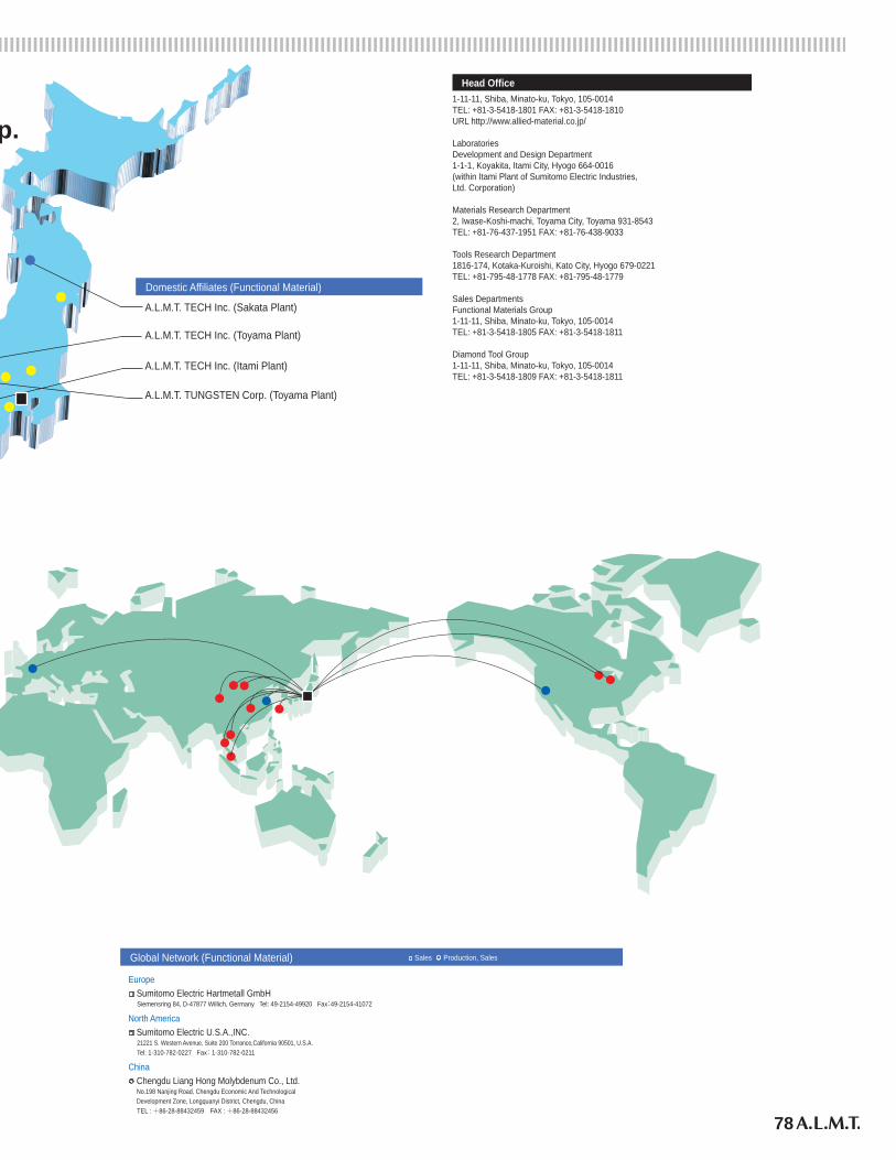
78
A.L.M.T. DIAMOND Corp. (Harima Plant)
A.L.M.T. DIAMOND Corp. (Shizuoka Plant)
Ajawi Diamond Industrial Co., Ltd.
A.L.M.T. TECH Inc. (Sakata Plant) A.L.M.T. TECH Inc. (Toyama Plant)
A.L.M.T. TECH Inc. (Itami Plant)
A.L.M.T. TUNGSTEN Corp. (Toyama Plant)
Based on the domestic production subsidiaries with high technologies, thesales network close to the local and overseas markets and the manufacturing affiliates overseas, A.L.M.T. Corp. serve society both at home and abroadwith reliable products
Global Network (Diamond Tool)
Domestic Affiliates (Diamond Tool) Domestic Affiliates (Functional Material)
North America Sumitomo Electric Carbide, Inc.
1001. Business Center Drive, Mt. Prospect, IL 60056-0545, U.S.A Tel: 1-847-635-0044 Fax: 1-847-635-9335
Sumitomo Electric Carbide, Inc. 14496 Sheldon Road, Suite 230, Plymouth, MI 48170, U.S.A. Tel: 1-734-451-0200 Fax: 1-734-451-5338
China Henan A.L.M.T. Whirlwind Diamond Wheel Co., Ltd.
200 Renmin Road, Changge City, Henan Province China 461500 TEL : +86-374-6108758 FAX : +86-374-6108859
Henan A.L.M.T. Whirlwind Diamond Wheel Co., Ltd. 200 Renmin Road, Changge City, Henan Province China 461500 TEL : +86-374-6108766 +86-374-6108768 FAX : +86-374-6108769
A.L.M.T. Diamond Dies(SUZHOU)Co.,Ltd. Unit 25D, 25E Of Suchun Industrial Square, #428 Xinglong Street Suzhou Industrial Park, Jiangsu, P.R. China 215021 TEL : +86-512-62836195~7 FAX : +86-512-62836176
Taiwan Chyi Meei Precision Industry Co.,Ltd.
7F, No.32, Lane513, Juikung RD., Neihu, Taipei, Taiwan (Far-East Hi-Tec. a Center) TEL : +886-2-26590955 FAX : +886-2-26572929
South East Asia A.L.M.T. Asia Pacific Pte. Ltd. No.2 Boon Leat Terrace #03-02/03 Harbourside 2 Singapore 119844 TEL : +65-6271-9252 FAX : +65-6274-2915
● A.L.M.T. Asia Pacific Pte. Ltd. A-3-1 Mines Waterfront Business Park No.3, Jalan Tasik, The Mines Resort City, 43300 Seri Kembangan, Selangor Darul Ehsan Malaysia TEL : +60-3-8945-1090~1 FAX : +60-3-8945-1092
A.L.M.T. (Thailand) Co.,Ltd. 90/2 Moo.9, Wellgrow Industrial Estate Bangna-Trad Road Km36, Bangwua, Bangpakong Chachoensao 24180 Thailand TEL : +66-38-522291~4 FAX : +66-38-522290
A.L.M.T. (Thailand) Co.,Ltd.) 54 B.B.Building, Room1511,15th Floor, Sukhumvit 21 Road (Asoke), North Klongtoey, Wattana,Bangkok10110 Thailand TEL:+66-2-2612231~2 FAX:+66-2-2612230
Global Network (Functional Material)
Europe Sumitomo Electric Hartmetall GmbH
Siemensring 84, D-47877 Willich, Germany Tel: 49-2154-49920 Fax:49-2154-41072 North America
Sumitomo Electric U.S.A.,INC. 21221 S. Western Avenue, Suite 200 Torrance,California 90501, U.S.A. Tel: 1-310-782-0227 Fax: 1-310-782-0211
China Chengdu Liang Hong Molybdenum Co., Ltd.
No.198 Nanjing Road, Chengdu Economic And Technological Development Zone, Longquanyi District, Chengdu, China TEL : +86-28-88432459 FAX : +86-28-88432456
1-11-11, Shiba, Minato-ku, Tokyo, 105-0014TEL: +81-3-5418-1801 FAX: +81-3-5418-1810URL http://www.allied-material.co.jp/
LaboratoriesDevelopment and Design Department1-1-1, Koyakita, Itami City, Hyogo 664-0016(within Itami Plant of Sumitomo Electric Industries,Ltd. Corporation)
Materials Research Department2, Iwase-Koshi-machi, Toyama City, Toyama 931-8543TEL: +81-76-437-1951 FAX: +81-76-438-9033
Tools Research Department1816-174, Kotaka-Kuroishi, Kato City, Hyogo 679-0221TEL: +81-795-48-1778 FAX: +81-795-48-1779
Sales DepartmentsFunctional Materials Group1-11-11, Shiba, Minato-ku, Tokyo, 105-0014TEL: +81-3-5418-1805 FAX: +81-3-5418-1811
Diamond Tool Group1-11-11, Shiba, Minato-ku, Tokyo, 105-0014TEL: +81-3-5418-1809 FAX: +81-3-5418-1811
Head Office
Sales ○ Production, Sales
Sales ○ Production, Sales
Technical & Reliable Network for A.L.M.T. Corp.
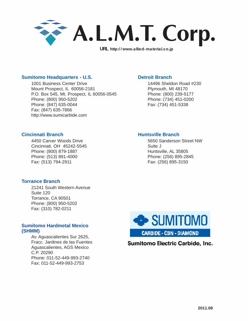
Huntsville Branch5650 Sanderson Street NWSuite JHuntsville, AL 35805Phone: (256) 895-2845Fax: (256) 895-3150
Torrance Branch21241 South Western AvenueSuite 120Torrance, CA 90501Phone: (800) 950-5202Fax: (310) 782-0211
Sumitomo Headquarters - U.S. Detroit Branch14496 Sheldon Road #230Plymouth, MI 48170Phone: (800) 239-5177Phone: (734) 451-0200Fax: (734) 451-5338
1001 Business Center DriveMount Prospect, IL 60056-2181P.O. Box 545, Mt. Prospect, IL 60056-0545Phone: (800) 950-5202Phone: (847) 635-0044Fax: (847) 635-7866http://www.sumicarbide.com
Cincinnati Branch4450 Carver Woods DriveCincinnati, OH 45242-5545Phone: (800) 879-1887Phone: (513) 891-4000Fax: (513) 794-2911
Sumitomo Hardmetal Mexico (SHMM)
Av. Aguascalientes Sur 2625,Fracc. Jardines de las FuentesAguascalientes, AGS MexicoC.P. 20290Phone: 011-52-449-993-2740 Fax: 011-52-449-993-2753
URL http://www.allied-material.co.jp
2011.08