2010112616578681
DESCRIPTION
2010112616578681TRANSCRIPT

HauserEndress
SF 206F/00/enrelease 09.97version 1
MicrowaveLevel MeasurementMicropilot FMR 130/131
Trouble Shooting
Micropilot Trouble Shooting
2 Endress+Hauser Maulburg
SF206F/00/en/09.97/1
1. Up-load FMR 130/1312. Error check V9H0
Constant error code? yes
yes
yes
yes
yesyes
yes
yes
yes
yes
yes
yes yes
no
no
no
no
no nono
nein
no
no no
Preventive action 1Installation ok?
Preventive action 2Tank mapping ok?
Check for previouserrors V9H1/V9H2
Error E 641 showingup sporadically?
see 3.1Page 12
see 2.1Page 10
see 2.2Page 11
Compare measuredvalue with actual level
Compare measuredvalue with actual level
Indicated level toolow?
Indicated level toolow?
Indicated level toohigh?
Indicated level toohigh?
Level indicationunstable?
level indicationunstable?
Typically close toantenna?
Constantdeviation?
see 3.4page 18
see 3.9page 26
see 3.5page 20
see 3.3page 16
see 3.3page 16
see 3.2page 13
see 3.8page 25
see 3.6page 22
see 3.7page 24
Typically only at endof measuring range?
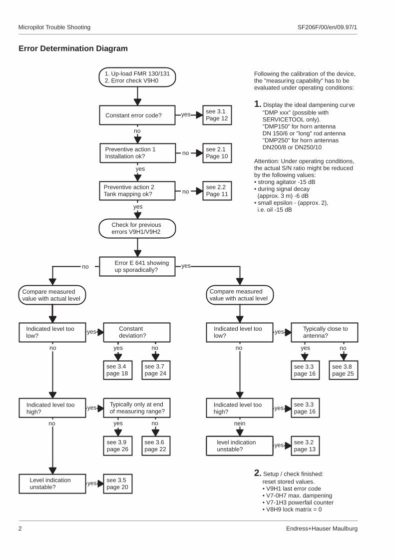
Error Determination Diagram
Following the calibration of the device,the "measuring capability" has to beevaluated under operating conditions:
Display the ideal dampening curve"DMP xxx" (possible withSERVICETOOL only)."DMP150" for horn antennaDN 150/6 or "long" rod antenna"DMP250" for horn antennasDN200/8 or DN250/10
Attention: Under operating conditions,the actual S/N ratio might be reducedby the following values:• strong agitator -15 dB• during signal decay
(approx. 3 m) -6 dB• small epsilon - (approx. 2),
i.e. oil -15 dB
1.
2. Setup / check finished:reset stored values.• V9H1 last error code• V7-0H7 max. dampening• V7-1H3 powerfail counter• V8H9 lock matrix = 0

SF206F/00/en/09.97/1 Micropilot Trouble Shooting
Endress+Hauser Maulburg 3
Contents
Page
1. Introduction . . . . . . . . . . . . . . . . 4
1.1 Information regarding additional documentation . . . . . . 4
1.2 Preface and security advise . . . . . . . . . . . 5
1.3 Connection of PC with FMR . . . . . . . . . . . 6
1.4 Upload and download of device data . . . . . . . . . 7
1.5 Envelope curve - explanation . . . . . . . . . . . 8
1.6 Envelope curve - display with various software . . . . . . 9
2. "Preventive measures". . . . . . . . . . . . . 10
2.1 Correct installation . . . . . . . . . . . . . . 10
2.2 Suppression of false echoes . . . . . . . . . . . 11
3. Error determination by symptoms. . . . . . . . . . 12
3.1 Error messages / error codes . . . . . . . . . . . 12
3.2 Signal cannot be evaluated, error E 641 (example 1) . . . . 13
3.3 Signal cannot be evaluated, error E 641 (example 2) . . . . 16
3.4 Incorrect measured value, indication constantly too low. . . . 18
3.5 Incorrect level indication (up to 35 cm) . . . . . . . . 20
3.6 Unstable indication (example 1) . . . . . . . . . 22
3.7 Unstable indication (example 2) . . . . . . . . . 24
3.8 Unstable indication (example 3) . . . . . . . . . 25
3.9 Unstable indication (example 4) . . . . . . . . . 26

Micropilot Trouble Shooting
4 Endress+Hauser Maulburg
1.1 Information regarding additional documentation
This brochure is meant as a suppor t tool for the commissioning of a microwave levelmeasurement and the diagnosis of problems occuring during the production process.
The problems and solutions described represent a collection of experiences and do notclaim to be complete.
Explanations of technical terms (like FAC, TDT, FEF ...) as well as their function and setupcan be found in the service info "Micropilot FMR 130, user information".
Additional instrument specific infos and hints for repair, exchange of modules, spare partsetc. is documented in the service info "Level measurement device FMR 130".
Instructions for installation, commissioning and operation are part of the operating manualBA 108F/00.
SF206F/00/en/09.97/1
1. Introduction

SF206F/00/en/09.97/1 Micropilot Trouble Shooting
Endress+Hauser Maulburg 5
1.2 Preface and security advice
The Micropilot FMR 13x is a Smart Field Transmitter for continuous level measurement, workingaccording to the microwave pulse time of flight principle. The working frequency of 5.8 GHz(6.3 for USA) is within the frequency band officially accepted industr ial applications. Theemitted low energy impulse of 1µW allows the use of this unit in non-metallic and openand is absolutely harmless for man and creature.
It has to be installed according to the respective national guidelines, if it is used in hazardouslocations. The device is available with various approvals.
A Micropilot FMR 130/131 must only be repaired and serviced by specialistsapproved by E+H. The corresponding service infos, all relevant guidelines,legal restrictions and approvals must be observed.
This brochure is meant as a suppor t tool for the user and maintenance staff in case of a failure.Please observe:
• Make sure that your specialists are well trained.
• Observe all safety regulations.
• The electronic compartment of the Micropilot provides ignition protectionclass Ex d, i.e. it must not be opened when powered.After switching off the power, a waiting period of 30 minutes has to be allowed.
forvessels
device versions
Horn antennaFMR 130
Process separation flangeFMR 130
Rod antennaFMR 131

SF206F/00/en/09.97/1Micropilot Trouble Shooting
Endress+Hauser Maulburg6
1.3 Connection of PC with FMR
service-connector
Depending on the available features of a measuring line, the technician can use thefollowing devices and software:
• Laptop, Notebook or Desktop (System DOS)
• E+H-software- Service-Tool, Order No. see Service-Interface- Commutool, Order No. 015 789 - 0000- Commuwin II, Order No. FXS 113 - _ _- Operating Monitor
Commutec, Order No. 014 880 - 0000- Fieldmanager, Order No. 942 135 - 0000
• Interface between Micropilot and Computer- Interface FXA 675, Order No. 942 194 - 2000- Interface ZA 672, Order No. 919 058 - 1040- Silometer FMX 770, Order No. 942 160 - 0041- Commubox FXA 191, Order No. 942 337 - 0000- Commubox FXA 192, Order No. 209 227 - 0000- Service-Interface FMR, Order No. 016 154 - 0000- RS485-Phoenix-Adapter, Order No. 016 398 - 0000
The following drawings show possible combinations of connections to a PC and therequired software which allow the display of the envelope curve of a signal.
Connection with Service-Interface FMU/FMR
RS232
RS232
4 ... 20 mAactive/passiveINTENSOR-Protocol
4 ... 20 mAactive/passive/communication
FXA 191
Connection with Intensor-Protocol and Commubox FXA 191
Servicetool
Commutool
Commuwin
Commutec User Progr.
Fieldmanager
Servicetool
Commutool
Commuwin
Commutec User Progr.
Fieldmanager
Servicetool
Commutool
Commuwin
Commutec User Prog.
Fieldmanager
Sof
twar
e-ve
rsio
n (m
in.)
Sof
twar
e-ve
rsio
n (m
in.)
Sof
twar
e-ve
rsio
n (m
in.)
Env
elop
ecu
rve
- di
spla
yE
nvel
ope
curv
e -
disp
lay
Env
elop
ecu
rve
- di
spla
y
Env
elop
ecu
rve
- st
orag
eE
nvel
ope
curv
e -
stor
age
Env
elop
ecu
rve
- st
orag
e
Up-
Dow
nloa
dU
p-D
ownl
oad
Up-
Dow
nloa
d
availablesoftware
availablesoftware
availablesoftware
•The corresponding communicationprotocol has to be selected at theCommubox with a switch.
• The input circuit is intrinsically safe.
• If the micropilot is installed in an ex-zone, a fire permit is requiredfor the connection of the service interface.
• Input and output of the service interface are galvanically separated
• Power is supplied by the PCvia the RS232 interface.
3.0 X X X X
1.3 X X X
1.41 X X 1.41
RS232
4 ... 20 mAactive/passiveHART-Protocol
FXA 191
Connection with HART-Protocol and Commubox FXA 191
• The corresponding communicationprotocol has to be selected at theCommubox with a switch.
• The input circuit is intrinsically safe. • Power is supplied by the PCvia the RS232 Interface.
Software,Hardware
sele
ctiv
eD
ownl
oad
TD
Tse
lect
ive
Dow
nloa
dT
DT
*
*
*Only one envelope curve can be stored.
*Only one envelope curve can be stored.
sele
ctiv
eD
ownl
oad
TD
T

Micropilot Trouble Shooting
7Endress+Hauser Maulburg
SF206F/00/en/09.97/1
RS232
FXA 192
RS485-Phoenix-Adapter
E+H-Rackbus
Rackbus
Rackbus
Rackbus
RS232
RS232
RS232
4 ... 20 mAactive/passive
4 ... 20 mApassive
4 ... 20 mApassive
4 ... 20 mAactive/passive
Connection with Interface FXA 675 and ZA 672 using RS485-Protocol
Connection with Silometer FMX 770 and ZA 672 using INTENSOR-Protocol
Connection with power supply FXN 671 and ZA 672 using INTENSOR-Protocol
Connection with Commubox FXA 192 or RS485-Phoenix-Adapter using RS485-Protocol
RS485-Protocol
RS485-Protocol
FXA 675
FMX 770
FXN 671
ZA 672
ZA 672
ZA 672
Intensor-Protocol
Intensor-Protocol
• Connection only possible with passive current output.
• Connection only possible with passive current output.
Servicetool
Commutool
Commuwin
Commutec User Prog.
Fieldmanager
Sof
twar
e-ve
rsio
n (m
in.)
Sof
twar
e-ve
rsio
n (m
in.)
Sof
twar
e-ve
rsio
n (m
in.)
Sof
twar
e-ve
rsio
n (m
in.)
Env
elop
ecu
rve
- di
spla
yE
nvel
ope
curv
e -
disp
lay
Env
elop
ecu
rve
- di
spla
yE
nvel
ope
curv
e -
disp
lay
Env
elop
ecu
rve
- st
orag
eE
nvel
ope
curv
e -
stor
age
Env
elop
ecu
rve
- st
orag
eE
nvel
ope
curv
e -
stor
age
Up-
Dow
nloa
dU
p-D
ownl
oad
Up-
Dow
nloa
dU
p-D
ownl
oad
availablesoftware
availablesoftware
availablesoftware
availablesoftware
1.3 X X X
1.4 X
1.4 X
1.2 X X X
1.2 X X X
3.0 X X
3.0 X X X
5.2 X X X
5.2 X X
5.2 X X
1.3 X X X5.2 X X
1.2 X X X
sele
ctiv
eD
ownl
oad
TD
Tse
lect
ive
Dow
nloa
dT
DT
sele
ctiv
eD
ownl
oad
TD
Tse
lect
ive
Dow
nloa
dT
DT
*
*
*Only one envelope curve can be stored.
*Only one envelope curve can be stored.
(Fieldmanager onlywith Phoenix-Adapter)
(Commuwin IIonly with FXA 192)
Servicetool
Commutool
Commuwin
Commutec User Prog.
Fieldmanager
Servicetool
Commutool
Commuwin
Commutec User Prog.
Fieldmanager
Servicetool
Commutool
Commuwin
Commutec User Prog.
Fieldmanager
1.4 Upload and Download of device data
UploadAll operating and service programs feature an upload function. In addition to all matrix-data, thefactory TDT and the customer TDT are transfered. Depending on the protocol used, the uploadmay take several minutes.
DownloadThe different service programs (see above) allow a "selective" download. The choice is to onlysend the matrix data or all upload data to the FMR 13x.
Download to an identical device, eg in case of a memory loss or an inadvertantly overwriting."Selective" download in case of a change of device or copy of the matrix to different devices.This funtion is not suppor ted by all programs (eg. Commuwin II).
••

SF206F/00/en/09.97/1Micropilot Trouble Shooting
Endress+Hauser Maulburg8
1.5 Envelope curve - explanation
The Micropilot FMR 13x level measurement transmitter operates on the principle of pulsedradar. The carrier frequency is 5.8 GHz. The length of pulses created by the microwave moduleis 0.8 ns with a repetition frequency of 3.6 MHz. Short microwave pulses are emitted bythe antenna (horn or rod antenna), reflected from the surface of the material and then receivedby the antenna again. The distance to the surface of the material is proportional to the run timeof the microwave pulse.
The electromagnetic waves require between approx. 5 ns and 240 ns to cover this distance,depending on its length. The reflected signal is enlarged, using a sampling technique so thatthe signal is shown in the range of approx. 0.3 ms to 20 ms. The signal then has a carr ierfrequency of approx. 70 kHz.
The envelope curve created is demodulated, amplified and finally digitised in amicroprocessor.
A Laptop or PC, special E+H Software and the corresponding hardware are required toevaluate the envelope curve. For all possible combinations please see chapter "Connection of aPC to a measuring line FMR...".
The measuring signal within the envelope curve shows in chronological order the sendingpulse, the electrical decay and several echoes caused by installations inside the tank. Themaximum measuring time is depending on the longest distance. After this time, thenext cycle starts with a new sending pulse.
approx.
for evaluation
measuring
Distance sensor / level =velocity of light (km/s) x run time (ns)
2
Sending pulse withdecay time
False echo from installed items
False echoes from agitator blade
False echo from installed items
Level echo
run time
Example of a tank with stylized envelope curve
Measuringprinciple
Generating anenvelope curve

Micropilot Trouble Shooting
9Endress+Hauser Maulburg
1.6 Envelope curve - display with various software
The envelope curves shown below were stored at the same measuring situation, but withdifferent programs. The discrepancies are caused by the dynamic of the measuring signal.
Commutool requires the signal to be passed on from the 2-wire with Intensor-Protocolvia a Silometer FMX 770 or a power supply FXN 671 and a gateway ZA 672 to a PC.Therefore, the recording of an envelope curve will be slower than if the software service tool isused which directly utilizes the RS-232 protocol.
cable
SF206F/00/en/09.97/1
Envelope curve recordedwith Commutool V1.2
Envelope curve recordedwith Service Tool V3.04
false echo
workingecho
1. crosswindow suppression (V3H2)
Sendingpulse
displayof FAC
ringing edgeelectrical decay
Composition ofenvelope curve2. cross
measured distance (V0H8)

Micropilot Trouble Shooting
10 Endress+Hauser Maulburg
2.1 The correct installation
For a microwave level measurement special conditions have to be considered in order toguarantee a correct time of flight measurement. First requirement for a proper measurementis the correct installation of the Micropilot in the tank. Most incorrect measurements base on anecho signal being too weak due to false installation.
SF206F/00/en/09.97/1
Micropilot mountedon a nozzle
Object inside thesignal cone createsfalse echoes
The microwaves should have direct accessto the surface of the product.• Any object inside the signal cone creates an
echo. The closer the object, the stronger theecho will be.
• Strong echoes which cannot be avoided bychosing a different installation positioninterfere with the measurement and have tobe suppressed during the basic calibration.
Type 150/6" 200/8" 250/10"
angle 23° 19° 15°α
Beam angle of the horn antenna
> 30 cm tank wall tank walltank wall
Positioning of the Micropiloton the tank
Turning of flange and Micro-pilot. Stop pins parallel totank wall, optimumpolarisation.
Turning of flange and Micro-pilot. Stop pins in 90° angleto tank wall, test thispolarisation.
stop pins stop pins
Positioning,Polarisation
Installationof instrument
stop pin
h
The horn antenna should project a min. of1..2 cm out of the nozzle into the tank.
min.
Positioning ofantenna use spring washer for
plated flange
min. diamaterfor non-platedflange 78 mm
beam angle23°
h
l
100 %
Length of rod antenna max. nozzle heightl = 285 mml = 445 mm
h = 100 mmh = 200 mm
If feasible, use "long" rod antenna..
100 %
2. "Preventive Measures"
α

SF206F/00/en/09.97/1 Micropilot Trouble Shooting
Endress+Hauser Maulburg 11
2.2 Suppression of false echoes
A long nozzle with welding seams or improper edges leads to "nozzle prob lems". Windowmeasurements from outside through the tank with condensate at the window or humid /wet differences in the medium (epsilon-leap), items installed in the tank and mixing rotors , allthese disturbances create diffuse reflections . Thus, interference echos can be evaluated, if theiramplitude exceeds the amplitude of the echo caused the medium.
forming
by
The envelope curve represents an echo "picture" of the inside of the tank including allinstalled items and the medium. In order to suppress undesired disturbing echoes , a secondcurve, the TDT, overlays the actual envelope curve at a "distance" of 2-3 dB. This particularTDT preferably should be recorded in an empty tank (see in the operatingmanual BA 108F/00).
Only significant echoes will exceed this TDT and be evaluated. For the quantitative deter-mination of the echo the height of the peak is expressed as a damping (dB). For softwareversions up to 1.5, generally 10 % of the entered value are deducted. Furthermore, the"µ-factor" in V3H3 and the offset in V3H9 to be taken into consideration. By entering"111" in field V9H5, the factory-TDT will be reactivated.
description
have
TDT
TDTTime Dependent Threshold
FAC
FACFloating Average Curve
The FAC is similar to the TDT. Contrary to the TDT, the FAC automatically adjusts to thechanging disturbing echoes, created i.e. by build up and turbulances. The FAC onlysuppresses small disturbing echoes, all signals below this line are ignored. The echo signalwith the largest FAC distance is evaluated, provided no first echo factor is activated (servicematrix V7-2H1).
The FAC not only is recorded once, but gets calculated out of every envelope curve. Due to thispermanent calcuation, the time for each measuring cycle is increased by approx. 0.5 sec.
Level echo above the TDT
echo with the largestFAC distance
[dB]
[dB]

Micropilot Trouble Shooting
12 Endress+Hauser Maulburg
SF206F/00/en/09.97/1
3.1 Error messages, error codes
Coded error messages are displayed in field V9H0 of the operating matrix. In addition, for diagnosis the two last errors arestored in field V9H1 and V9H2. Attention: Before changing the electronics, perform a reset, eventually store and re-loadthe matrix.
Error codes
E 102 communication not yet W wait, after 1 min. check connection to UNIFACEestablished (UNIFACE)
E 106 download is active A wait until download is finished
E 111 RAM 1 faulty A exchange electronics (see Service-Info FMR 13x)
E 112 RAM 2 faulty A exchange electronics (see Service-Info FMR 13x)
E 113 EPROM faulty A exchange electronics (see Service-Info FMR 13x)
E 114 EEPROM faulty A exchange electronics (see Service-Info FMR 13x)
E 121 no calibration values for A perform D/A-calibration in service level; field V7-3H8 and V7-3H9current output (required after each change of electronics)
E 124 no calibration values for A re-determine z-distance, necessary after each change of eitherz-distance electronics or antenna (see Service-Info FMR 130, change of
antenna).
E 231 no sensor signal A up to software V1.4: incorrect TDT, delete factory- TDT and re-record.Software V1.5 + up: perform reset 333 (matrixfield V9H5)In case of hardware error, exchange electronics, (perform D/A-calibrationand enter new z-distance).
E 233 control of voltage for logarithm A hardware error, exchange electronics (perform D/A-calibration andstage not ok enter new z-distance).
E 501 no type of antenna selected W Enter type of antenna in service level field V7-5H1 (0=default)
E 511 factory-TDT not recorded W After each exchange of electronics, the TDT has to be recorded again(
E 512 ready for recording the TDT W Enter 4 or 5 in position V3H0 (
E 602 error in linearisation W Correct table, see operating manual BA108F/00.
E 613 simulation mode or optimation W Switch off simulation mode, matrixfield V8H0 = 0(V8H0 = 7 oder 8)
E 621 FMR 13x is stopped for service W During the recording of envelope curves via a service tool, thepurposes measuring speed is reduced. If no service tool is connected, enter a
"0" at position V7-1H5.
E 641 no usable signal A/W Echo is too weak; optimise sensor position (see chapter 2.1); recordenvelope curve (see chapter "PC connection") and optimiseparametration. Eventual electronic or HF incoupling faulty.
E 643 blocking distance almost reached A/W Check setting of safety distance in V8H7
E 651 dirty antenna. A/W Clean antenna. For software 2.0 + up, this error message has beendeleted.
(see also Service-Info FMR 130, chapter "exchange of antenna horn").
see also Service-Info FMR 130, chapter "exchange of antenna horn").
see Service-Info FMR 130, chapter "exchangeof antenna horn").
alarm/error = Awarning = W Diagnosis and solution
3. Error determination by symptoms

SF206F/00/en/09.97/1 Micropilot Trouble Shooting
Endress+Hauser Maulburg 13
3.2 Signal cannot be evaluated, error E641 (example 1)
Stair-like steps during operation
The line recorder shows stair-like steps, error message in matrix field V9H0 = E 641(signal cannot be evaluated)
Symptom
20 mA
4 mA
110%
-10%
current outputon HOLD
DiagnosisThe signal peak is barely visible on the evelope curve shown below. The reading of thesignal noise ratio in matrix field V7H3 is lower than the necessary S/N (indication in thisfield only if the service level is locked). The minimum S/N factor is entered in theservice level in matrix field V7-0H9.
error: level echo< 5 dB above FAC
Probable causeThe Micropilot is installed close to the tank (as close as 0.5 m from the wall), but notoptimally positioned. Depending on the positioning, an optimum signal can be achieved dueto the special emission characteristics of the microwave.
Relevant for the interpretation of the signal is a compar ison of the actual S/N factor(matrix field V7-0H8 on the service level) with the minimum S/N factor (V7-0H9). Thedefault value of the minimum S/N factor is 5 dB.
wall
[dB]

Micropilot Trouble Shooting
14 Endress+Hauser Maulburg
Error E641solution 1
error E641solution 2
SF206F/00/en/09.97/1
tankwall stop pins
should beparallel totank wall
turnflange Loosen and turn flange together with
Micropilot's housing until the stoppins are parallel to the tank wall.
•
••
•
Activate operating mode "optimising" by entering "8" in matrix field V8H0.Condition: V0H8 actually shows the correct distance to the level (no E641).
Choose matrix field V9H6 "sensor optimising".
While turning flange plus micropilot on the tank, watch indication in matrix fieldV9H6. Goal is to minimize this reading. Important: Value in field V0H8 should notchange significantly.
After optimizing, the Micropilot has to be fixed in this position and operating mode "level" inmatrix field V8H0 = 0 has to be selected.
slowly
As an alternative, the sensor position can be by maximizing the S/N factor.
Turn flange until stop pins are parallel to tank wall (see above).
Turn flange, until S/N factor in matrix field V7H3 (V 1.5) resp. V7H1 (software 2.0) showshighest reading. The service matrix has to be locked in order to show any indication(V8H9 333 or 5621).
If the envelope curve of the signal can be checked with a Service-Tool or Commutool etc,the Micropilot should be adjusted to the optimum echo resp. the weakest disturbance echo.
After optimizing, fasten the Micropilot in this position to the flange .
optimized
••
•
•
≠ ≠
error E641probable cause 2
The antenna of the Micropilot is too small.The size of the horn antenna determines the measuring range of the instrument.
If possible, attach a larger antenna horn to the Micropilot.However, consider that a larger antenna might not fit into the tank.
If the nozzle is too small, a larger antenna can be mounted from inside through a manhole .
If the nozzle is too small for a larger sensor, an antenna extension, TYP FAR 10 can beused (see also BA 108F/090).
•
••
small antenna horne.g.100/4"
larger antenna horne.g.150/6"does not fit into thenozzle in this example
larger antenna horn withextension
solution

SF206F/00/en/09.97/1 Micropilot Trouble Shooting
Endress+Hauser Maulburg 15
The Micropilot is mounted above a baffle, thus the material surfface is very turbulent. Dueto the diffuse reflexion of the microwave, the signal is very weak.
Error E641Probable cause 3
SolutionChange location of Micropilot.
A change of location can also be useful if theMicropilot is mounted above another sourceof disturbance (level limit probe or otherinstallations) or above the filling stream.

Micropilot Trouble Shooting
16 Endress+Hauser Maulburg
3.3 Signal cannot be evaluated, error E641 (example 2)
Loss of signal in almost full tank or at long measuring distances
With an almost filled tank, a "step" on the line recorder . The S/N factoris too small at full tank, no signal can be . Matrixfield V9H0 showserror code E 641 (no usable signal)
showsevaluated
SF206F/00/en/09.97/1
Symptom
20 mA
4 mA
FAC
Echo
The distance to the FAC is only approx. 3 dBbut should be > 5dB.
e.g. 1m
Probable cause The FAC is activated (V3H0 = 1 or 3). The arithmetic average of the FAC istoo high, thus the correct level echo does not exceed the FAC enough to beevaluated (S/N-factor must be > 5 dB).
Solution 1
Window suppression
Attention:
If there is sufficiant distance between the flange andthe maximum level, a window suppression can beperformed in this range. Enter distance [m] fromsensor in field V3H2, (see operating manualBA 108F/00).
If the level reaches the suppression range,a wrong measurement may result (please see V8H6and H7).A1
A2FAC
The starting point of the FAC is generally positioned on theenvelope curve at the beginning of a measuring cycle (point A1).Based on this position, the average value for the FAC is calcula-ted. This point is in the area of the sensor "ringing" and, therefore,the calculated value is still very high. If a level echo is close tothis area, it might be "covered" by the FAC. If the starting point ofthe measuring cycle is positioned at A2 (by means of a windowsuppression, hatched area), the FAC is positioned lower and thelevel echo might be clearly above the FAC.
» 6 dB
Current output on "HOLD"< 100%

SF206F/00/en/09.97/1 Micropilot Trouble Shooting
Endress+Hauser Maulburg 17
Solution 2
Solution 3
Suppression of false echo
TDT
false echo
1. Record a partial TDT. Enter 5 in matrix field V3H0. AlarmLED flashes and matrix field V9H0 indicates code E512(ready for recording TDT).
2. Empty tank to lowest possible level. Switch agitator on ifinstalled. Enter distance (m) to actual level in matrixfield V3H1.Wait approx. 1.5 min until TDT is recorded, then enter"2" in matrix field V3H0 (TDT on).
The TDT is now positioned above the false echo, thus thefalse echo is suppressed.With increasing level, the level echo rises towards 100 %but remains above the TDT and is properly evaluated.Hint: In case of an incorrect reset in field V9H5 thecustomer TDT can be deleted!
Use of larger antenna
α = 15°
α = 18°
α = 23°
5 m
10 m
15 m
20 m
25 m
30 m
35 m
0 44 88
Ran
ge
DN / ANSI100 mm / 4"150 mm / 6"200 mm / 8"250 mm / 10"
α30°23°18°15°
The beam area of the horn antenna deter-mines the measuring distance. The increasedfocusing of the electromagnetic field by largerantenna horns results in a higher echoamplitude.
At -3 dB (50%) of the maximum of the beamarea the sides are defined, resulting in thevarious beam angles.
The table shows various beam anglesdepending on the size of the antenna.
With a wider beam area, i.e. smaller antennas,the signal disappears in the noise indistances. Thus, it is always advantageous touse a larger antenna.
(hints how to change an antenna -see page 14)
shorter
beam areas of horn antennas
The 100 mm antenna isnot designed for free spacemeasurements.
corresponds to the long rodantenna, 445 mm, at the FMR 131
horn antenna FMR 130
*
*

Micropilot Trouble Shooting
18 Endress+Hauser Maulburg
SF206F/00/en/09.97/1
3.4 Incorrect measured value, indication constantly too low
20 mA
4 mA
V +
H - E
H8
V03.50
Endress+Hauser
3.20 m
0.30 m value too low
Symptom The level indication is too low by several cm (max. 30 cm) resp. the measured distancein matrix field V0H8 is too high by the same amount.
Effect The offset remains constant for the complete level range.
The speed of the Microwave pulse inside the extension part is lower than inside the free tank,thus a constant run time error occurs.
In order to compensate this error, an offset value is calculated from the extension's geometricaldata (diameter and length) and entered into field V3H9 (eventual the matrix has to beunlocked: V8H9 = 333, 130 or 5621).
An antenna extension is used.
matrix
Probable cause
length L1 of antenna extension [mm]
100 200 300 400
-0.0508 -0.1016 -0.1524 -0.2032
-0.034 -0.068 -0.102 -0.136
Ø d1[mm]
40
46
L1 d1
Calculation of offset:
offset [m] = -0.508 x L1 [m] for Ø 40 mmoffset [m] = -0.340 x L1 [m] for Ø 46 mm
The calculated value has to be entered as avalue in field V3H9.The table shows offset values for the most commonantenna extensions.
negative
insidediameter
Solution

Correct microfactor
Caution:
Practical determination:
Calculation of microfactor ( = Ø tube [mm]; d < 30 mm !)
The value of the theoretical microfactor is entered in matrix field V3H3 (value < 1).
This calculation is only valid for metal stilling wells or bypasses, not for metallizedglass tubes. Microwaves would enter the glass, thus reducing the speed further. Dueto this reason, the microfactor cannot be calculated.
As an alternative, the microfactor can be determined by a manual level measurement.
MF = 1 - (917.5 : d ) d√ 2
even
SF206F/00/en/09.97/1 Micropilot Trouble Shooting
Endress+Hauser Maulburg 19
Probable causeThe measuring point is in a stilling well or bypass.The speed of the microwave pulse inside the pipe is lower than inside the free tank. Therun time error is increasing with increasing distances.measuring
MF =actual level [m]
displayed level in V0H8 [m]
stilling well
During a manual level measurement, the largest possible distance should be used. Thedetermined microfactor is entered in matrix field V3H3 (value always < 1).
bypass
Solution

Micropilot Trouble Shooting
20 Endress+Hauser Maulburg
SF206F/00/en/09.97/1
3.5 Incorrect level indication (up to 35 cm difference)
Symptom For certain reproducible levels the echo impulse is deformed. It is gettingwider, shows two peaks ("camel humps") and the indicationup to 35 cm.
varies
This envelope curve shows the first maximum being evaluated. Theevaluation is correct, until . . .
. . . the first maximum is getting flat. Then, the 2nd maximum isevaluated.
Reason Multiple reflexions• The Micropilot is mounted in the center of the tank lid.• It is a narrow tank..• Only the short horn antenna (100 mm) is used.• The material surface inside the tank is smooth and .• There is oil on water.• Medium with low dielectric constant and tank with metallic flat
bottom or stilling well.
All these factors lead to multiple reflexions, usually several factorsapply simultaneously.
level
up to 35 cm

SF206F/00/en/09.97/1 Micropilot Trouble Shooting
Endress+Hauser Maulburg 21
Software settings
• First echo factor,
• Envelope curve smoothing,
• Ramp parameter,
Change of installation location or of size of horn antenna
•
•
evaluates the first reflection, it createsa peak (see envelope curves shown on previous page).
the smoothing of the envelope curve is setin service matrix field V7-2H6 (default = factor 4).By disabling this smoothing (enter 0) all peaks in the envelope curve remain
or
the peaks get "rounded" by a strong smoothing (enter 4...6 in field V7-2H6). Thus, the chanceof evaluating a false echo is reduced. However, the S/N factor can become too small andthe signal gets lost.
moves the evaluation to the rising ramp of an echo signal. The measuredvalue moves down the signal ramp by the dB-value entered in service matrix (field V7-1H8).However, once half of the S/N factor (field V7-0H8) has been reached, the parameter switchesto 0 dB.
Do not mount Micropilot in the center of the tank, closer to the side.
Use the largest possible horn antenna, eventually mount a larger antenna from theinside of the tank by using an extension through the nozzle (see operating manualBA 108F/00.)
provided
but
Solution 1
Solution 2
For a flat wide echo, no defined maximumcan be recognised.
eg. 3 dB
With a ramp parameter (in this case3 dB), the measuring uncertaintybecomes smaller due to the steeperramp.The evaluation moves on the risingflank by the value entered in fieldV7-1H8.
envelope curve without smoothing envelope curve with smoothingThe amplitude of the signal is reduced.
In case of problems with these software settings or if no solution canbe found, please inform E+H service!

Micropilot Trouble Shooting
22 Endress+Hauser Maulburg
SF206F/00/en/09.97/1
3.6 Unstable indication (example 1)
Variations towards "full" or constantly higher value
The indication varies towards "full tank".Symptom
20 mA
4 mA
3.50 m
5.00 m
0 m
V V V+ + +
H H H- - -E E E
H H H9
V0
V3.50 5.00 3.50
Endress+ Endress+ Endress+Hauser Hauser Hauser
Probable cause Disturbances close to or in antenna
build up in antenna (irrelevantif outside of the antenna)
installations or edges in the upperpart of the tank
build up
installations
Solution 1
Solution 2
If the distance between flange and max. level is sufficiant, suppress this range (windowsuppression). Enter distance (m) between flange and level in matrix field V3H2.
If level reaches the suppressed range, risk of erratic measurement. (See safetyregulations in operating manual BA 108F/00.)
Suppress false echoes: record a partial TDT.
empty tank to lowest possible levelif agitator exists, switch it on resp. position agitator blade manually underneath antenna.Matrix field V8H9 = enter 130 (unlock matrix)Matrix field V3H0 = enter 5 (record par tial TDT, error LED flashes, error E512 is shown)Matrix field V3H1 = enter ... m (distance [m] to level), wait approx. 1.5 min. until recordingfinished. The distance entered is automatically reduced 10 %. Ignore error indicationwhen using the service software.Matrix field V3H0 = enter 2 or 3 ("TDT on" or "FAC and TDT on")
Attention:
•••••
•
by
edge
9 9V0 0

SF206F/00/en/09.97/1 Micropilot Trouble Shooting
Endress+Hauser Maulburg 23
Probable cause 2No smoothing of envelope curve selected (V7-2H6 = 0)
Envelope curve shows narrow small false echoes
Solution 1Activate envelope curve smoothing:••
•
Suppression of false echoes: recording of partial TDT•••••
•
Unlock service level in matrix field V8H9, enter "333" or "5621".Enter smoothing factor between 2...4 in matrix field V7-2H6 of service level..Envelope curve should now be smoothened to the point that the actual level echo can beclearly detected.Lock service level by entering 130 in matrix field V8H9.
empty tank to lowest possible levelif agitator exists, switch it on.Matrixfeld V8H9 = enter 130 (unlock matrix)Matrixfeld V3H0 = enter 5 eingeben (record par tial TDT, error LED flashes,error E512 is shown)Matrixfeld V3H1 = enter ... m (distance [m] to level, wait approx.1.5 min. until recording isfinished. The entered distance is automatically reduced by 10 %. Ignore error indication whenusing the service software.Matrixfeld V3H0 = enter 2 or 3 ("TDT on" or "FAC and TDT on")
Solution 2
false echo level echofunction ofsmoothingsee page 21

Micropilot Trouble Shooting
24 Endress+Hauser Maulburg
SF206F/00/en/09.97/1
3.7 Unstable indication (example 2)
Indication changes towards "empty"
Symptom Indication changes significantly "empty tank", there are erratic "empty" readings.towards
20 mA
4 mA
3.50 m
5.00 m
0 m
V V V+ + +
H H H- - -E E E
H H H9 9 9
V0 0 0
V V3.50 0.00 3.50
Endress+ Endress+ Endress+Hauser Hauser Hauser
Probable cause Multiple relexions•••
totally calm medium surfaceusually occurs at levels above 50 %due to a very good reflection at medium and shaped cover (dome ceiling) multiplereflexions occur depending on actual level
spherical
level echodoublereflection
Solution Increase first echo factor••
•
unlock service level in matrix field V8H9, enter "333" or "5621".Increase the actual first echo factor in service level matrix field V7-2H1 (i.e. to 30 [dB]) (theactual value depends on the operating mode selected in V0H3).Lock service level in matrix field V8H9 (enter 130).

SF206F/00/en/09.97/1 Micropilot Trouble Shooting
Endress+Hauser Maulburg 25
3.8 Instable Indication (example 3)
Indication changes towards "empty"
Indication significantly changes "empty tank", there are erratic"empty" readings. Sporadically, error message E 641 appears (no usablesignal).
towards Symptom
20 mA
4 mA
3.50 m
5.00 m
0 m
V V V+ + +
H H H- - -E E E
H H H9 9 9
V0 0 0
V V3.50 0.00 3.50
Endress+ Endress+ Endress+Hauser Hauser Hauser
Probable cause••
Strong turbulences on mediumAntenna is too small and / or ends already in nozzle
Due to the turbulences on medium surface, signal changes significantly.Weak but detectable multiple reflexions are evaluated.
surface
antenna hornends alreadyin nozzle
mount largerantenna horn
install antennahorn withantenna extension
antenna horntoo small
SolutionMount a larger antenna:
•••••
•
If nozzle is too narrow, mount a larger antenna horn with an antenna extension from insidethe tank.
empty tank to lowest levelif agitator exists, switch it on.Matrix field V8H9 = enter 130 (unlock matrix)Matrix field V3H0 = enter 5 (record TDT, error LED flashes, error E512 is shown)Matrix field V3H1 = enter ... m (distance [m] to level, wait approx. 1.5 min. until recordingis finished. The distance is automatically reduced 10 %. Ignore error indication whenusing the service software.Matrix field V3H0 = enter 2 or 3 ("TDT on" or "FAC and TDT on")
partial
by

Micropilot Trouble Shooting
26 Endress+Hauser Maulburg
SF206F/00/en/09.97/1
3.9 Unstable Indication (example 4)
Permanently changing level indication, especially when tank empty
Symptom Erratic readings (different level indications) at empty tank.
20 mA
4 mA
5.00 m
0 m
Probable cause Multiple reflexions
Moving false signals, i.e. caused by interferences with changing location.These signals cannot be suppressed by means of the TDT.Despite the good S/N-ratio of the real level signal, these false reflections might be evaluated(first echo factor is active).
Solution 1. Switch on FAC (matrix V3H1 = 1)
2. Determine S/N-factor of false reflections by envelope curve recording and evaluation.
3. Increase minimum S/N-ratio (in service matrix V7-0H9), so that the false reflections are notdetected anymore by the first echo factor. Increase, for example, the S/N-ratio by +3dBand check measurement again.
15%
28%
0%8%
57%
16%
8%
45%
levelechomultiple reflections