2010-04 pwi april newsletter
DESCRIPTION
2010-04 PWI April NewsletterTRANSCRIPT
The Permanent Way Institution South Australian Section Incorporated
GPO Box 318
Belair SA 5052
NEWSLETTER FOR APRIL 2010
Next Meeting – 8th April 2010
The next meeting of the PWI SA Section will be held on Thursday 8th April 2010. This joint meeting with the RTSA will be a site visit to inspect the various:
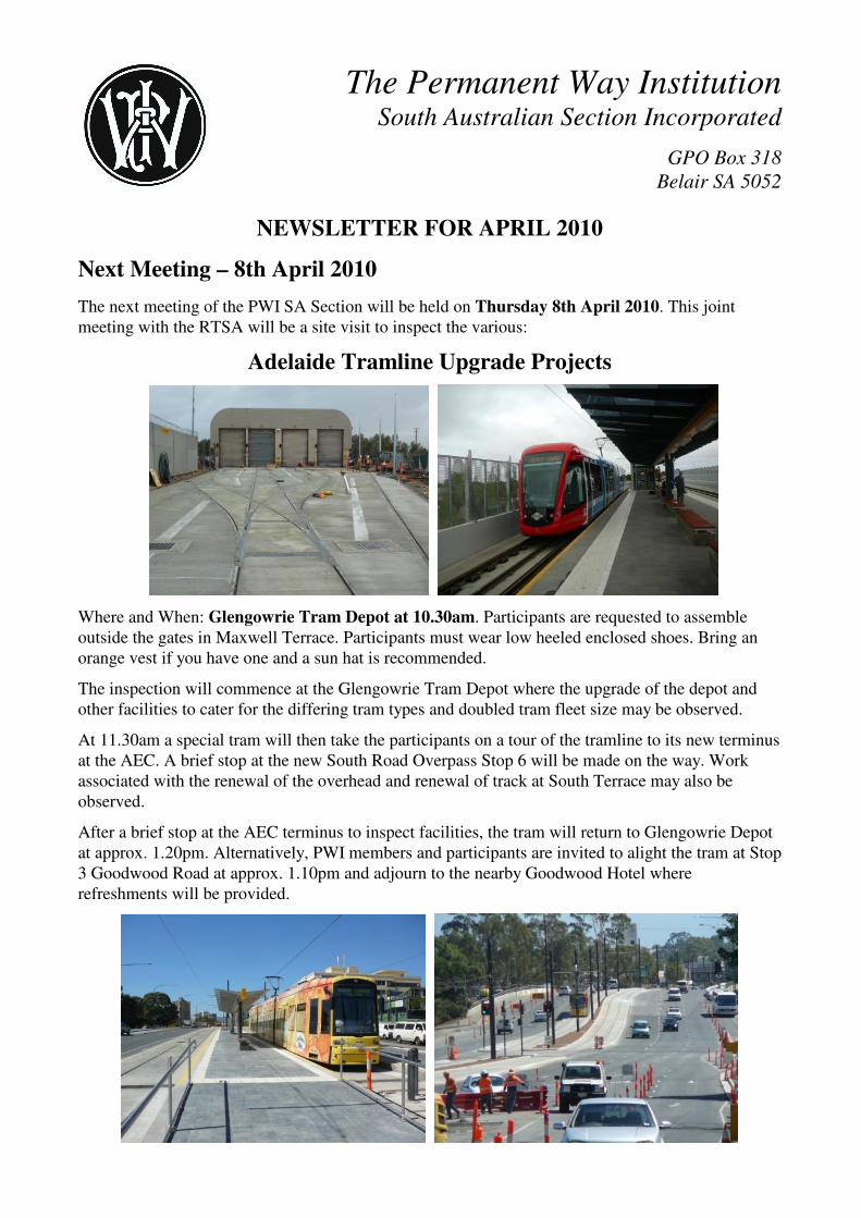
Adelaide Tramline Upgrade Projects
Where and When: Glengowrie Tram Depot at 10.30am. Participants are requested to assemble outside the gates in Maxwell Terrace. Participants must wear low heeled enclosed shoes. Bring an orange vest if you have one and a sun hat is recommended.
The inspection will commence at the Glengowrie Tram Depot where the upgrade of the depot and other facilities to cater for the differing tram types and doubled tram fleet size may be observed.
At 11.30am a special tram will then take the participants on a tour of the tramline to its new terminus at the AEC. A brief stop at the new South Road Overpass Stop 6 will be made on the way. Work associated with the renewal of the overhead and renewal of track at South Terrace may also be observed.
After a brief stop at the AEC terminus to inspect facilities, the tram will return to Glengowrie Depot at approx. 1.20pm. Alternatively, PWI members and participants are invited to alight the tram at Stop 3 Goodwood Road at approx. 1.10pm and adjourn to the nearby Goodwood Hotel where refreshments will be provided.
PWI SA Section Newsletter April 2010 – Page 2 of 31
LAST MEETING
The last meeting was held 4th February 2010. At this meeting Max Shuard and Stephen Townsend gave a presentation about the STORE 2009 Asia Metro System. Max described the tour while Stephen talked about the learnings. A paper based on their talk follows.
STORE 2009 - Asia Metro Systems Max Shuard & Stephen Townsend
Description of STORE 2009
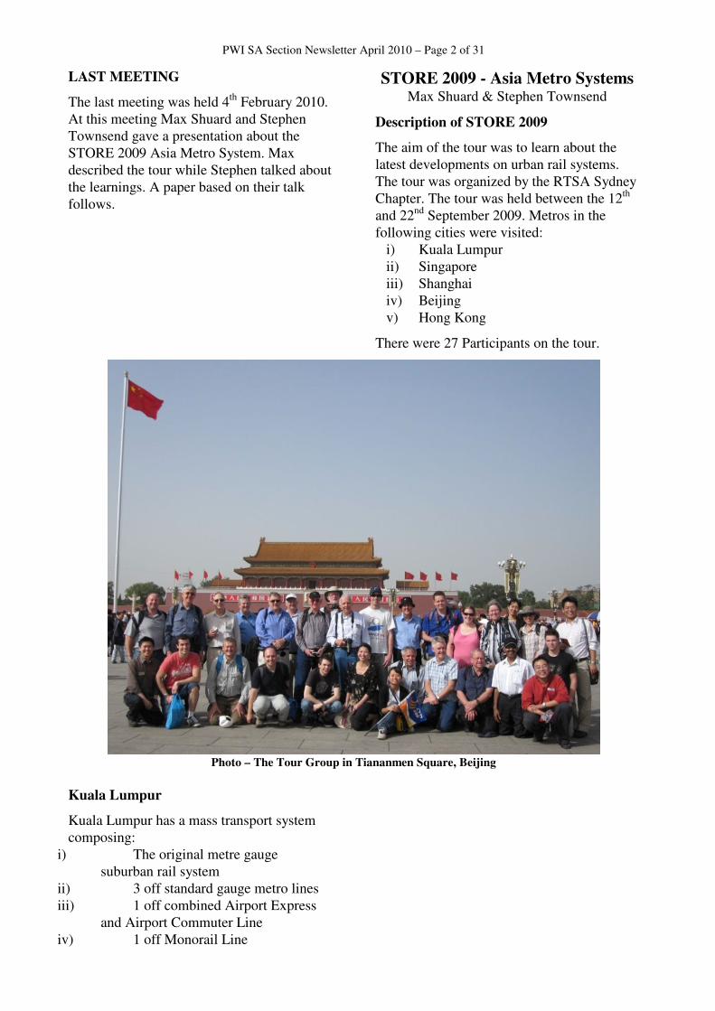
The aim of the tour was to learn about the latest developments on urban rail systems. The tour was organized by the RTSA Sydney Chapter. The tour was held between the 12th and 22nd September 2009. Metros in the following cities were visited:
i) Kuala Lumpur ii) Singapore iii) Shanghai iv) Beijing v) Hong Kong
There were 27 Participants on the tour.
Photo – The Tour Group in Tiananmen Square, Beijing
Kuala Lumpur
Kuala Lumpur has a mass transport system composing:
i) The original metre gauge suburban rail system
ii) 3 off standard gauge metro lines iii) 1 off combined Airport Express
and Airport Commuter Line iv) 1 off Monorail Line

PWI SA Section Newsletter April 2010 – Page 3 of 31
Figure – Kuala Lumpur Rail Network
The standard gauge and monorail lines were constructed and operated separately by private enterprise. With the except of the airport line all have been taken over by Government. They are still run as separate entities but integration of the system is being implemented (ticketing and interchanges). Full integration of the systems is not possible due to the differing designs that have been built.
Photo – Kuala Lumpur showing Various Lines
Left – Airport Express, Centre – Metre Gauge Lines, Right – Kelana Jaya Line
Sentral to Titiwangsa Monorail
The Sentral to Titiwangsa Monorail opened 2003. It has a route length of 8.6km with 11 off elevated stations.
Photo – KL Monorail
The system is operated by 2 car sets with a total capacity of 214 passengers (48 seated). A project to increase the set size to 4 cars is currently underway. The average speed along the line is 30km/hr. The service is operated at a frequency of approximately 4 to 5 minutes. The route capacity is approximately 3416 per hour per direction. The end to end journey time is approximately 20 minutes.
The monorail is elevated for its entire length with the track located on pre-stressed concrete girders, each designed for its individual location. Turnouts (or their monorail equivalent) are achieved by the use of a segmented steel monorail girder that can moved laterally to join the fixed sections of different tracks. The turnouts take approximately 7 seconds to move from one track to the other.
Photo – Monorail Turnout at KL Sentral Terminus
(Turnout at mid-point of movement)
The monorail vehicles are 21.6m long by 3 m wide and are composed of two articulated cars. The cars run on rubber tyres, which are used both for support, traction and guidance. Power is 750 V DC and is supplied by a third rail located to the side of the monorail.
The maximum operational grade is 6% and the minimum curvature is 50m radius. The maximum speed is 55km/hr.
KL Rapid
KL Rapid operates two lines, the Putra to Kelana Jaya Line and the Ampang to Sri Petaling Line.
PWI SA Section Newsletter April 2010 – Page 4 of 31
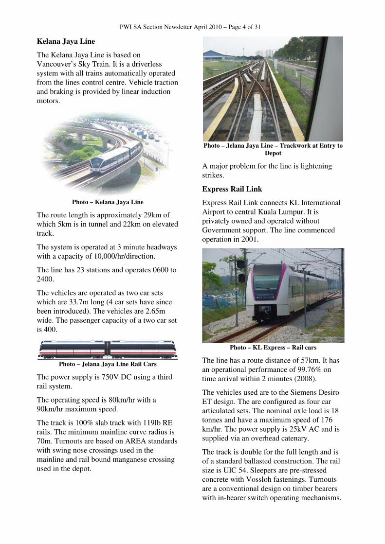
Kelana Jaya Line
The Kelana Jaya Line is based on Vancouver’s Sky Train. It is a driverless system with all trains automatically operated from the lines control centre. Vehicle traction and braking is provided by linear induction motors.
Photo – Kelana Jaya Line
The route length is approximately 29km of which 5km is in tunnel and 22km on elevated track.
The system is operated at 3 minute headways with a capacity of 10,000/hr/direction.
The line has 23 stations and operates 0600 to 2400.
The vehicles are operated as two car sets which are 33.7m long (4 car sets have since been introduced). The vehicles are 2.65m wide. The passenger capacity of a two car set is 400.
Photo – Jelana Jaya Line Rail Cars
The power supply is 750V DC using a third rail system.
The operating speed is 80km/hr with a 90km/hr maximum speed.
The track is 100% slab track with 119lb RE rails. The minimum mainline curve radius is 70m. Turnouts are based on AREA standards with swing nose crossings used in the mainline and rail bound manganese crossing used in the depot.
Photo – Jelana Jaya Line – Trackwork at Entry to
Depot
A major problem for the line is lightening strikes.
Express Rail Link
Express Rail Link connects KL International Airport to central Kuala Lumpur. It is privately owned and operated without Government support. The line commenced operation in 2001.
Photo – KL Express – Rail cars
The line has a route distance of 57km. It has an operational performance of 99.76% on time arrival within 2 minutes (2008).
The vehicles used are to the Siemens Desiro ET design. The are configured as four car articulated sets. The nominal axle load is 18 tonnes and have a maximum speed of 176 km/hr. The power supply is 25kV AC and is supplied via an overhead catenary.
The track is double for the full length and is of a standard ballasted construction. The rail size is UIC 54. Sleepers are pre-stressed concrete with Vossloh fastenings. Turnouts are a conventional design on timber bearers with in-bearer switch operating mechanisms.
PWI SA Section Newsletter April 2010 – Page 5 of 31
Aspects of the Operations and Signaling system are:
i) Multi-Aspect Signals ii) Train Management System
with continuous automatic train protection
iii) Simplified bi-directional capability
iv) Train protection provided by axle counters
v) Minimum possible Headway – 2 minutes
vi) Telecoms – digital transmission SCADA
vii) Communications – PA, CCTV, Radio
Singapore
Land Transport Authority
The Land Transport Authority is responsible for the planning and delivery of the Singapore transport system. These responsibilities include:
Land Transport Master Plan
The Land Transport Master Plan envisages an expenditure of $S540 Billion over the next 10 to 15 years with the aims to increase Public Transport usage from 52% to 70% and to provide a congestion free road system. It is this latter aim that drives the public transport usage target in order to remove unnecessary road transport demand by making public transport viable and convenient.
Public Transport Operations
Public transport is provided by two companies under contract to the Land Transport Authority. The companies are SMRT and SBS Transit. The companies may operate rail, bus and taxi systems.
Electronic Fare Ticketing System
Singapore has a fully operational contactless electronic fare ticketing system. Fares are determined by the length of the journey using a tag on, tag off system.
Singapore’s population is approximately 4.2M of which approximately 2.5M use public transport daily requiring a daily
transport task of 5M rides and 3.5M Journeys.
95% of journeys are completed within 45 minutes.
The average fare is $S0.90. This is highly affordable as it represents <8% of the disposable income of the bottom 10% of income earners ($S1000/month).
Public transportation operational costs are 100% self funded from fares.
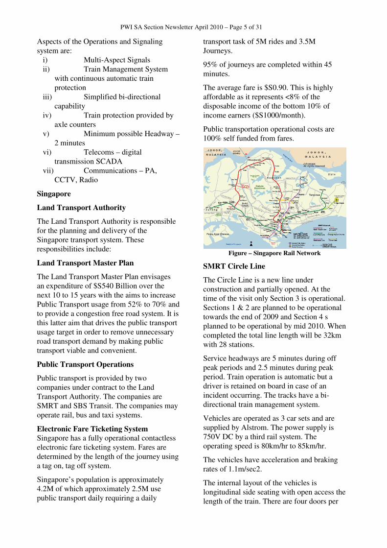
Figure – Singapore Rail Network
SMRT Circle Line
The Circle Line is a new line under construction and partially opened. At the time of the visit only Section 3 is operational. Sections 1 & 2 are planned to be operational towards the end of 2009 and Section 4 s planned to be operational by mid 2010. When completed the total line length will be 32km with 28 stations.
Service headways are 5 minutes during off peak periods and 2.5 minutes during peak period. Train operation is automatic but a driver is retained on board in case of an incident occurring. The tracks have a bi-directional train management system.
Vehicles are operated as 3 car sets and are supplied by Alstrom. The power supply is 750V DC by a third rail system. The operating speed is 80km/hr to 85km/hr.
The vehicles have acceleration and braking rates of 1.1m/sec2.
The internal layout of the vehicles is longitudinal side seating with open access the length of the train. There are four doors per
PWI SA Section Newsletter April 2010 – Page 6 of 31
side to provide rapid boarding and alighting and an escape door is provided at each end.
SMRT Kym Chuan Depot
This depot cost approx. $S400M and was opened in 2006. The depot services trains operating on the Circle Line.
Photo – Maintenance Hall – Kym Chuan Depot
The depot provides servicing, maintenance and stabling facilities for a total of 72 off 3 car train sets. The depot provides track and tunnel maintenance equipment storage and stabling. The Circle Line control centre is also located at the depot. Except for some office space, the depot is located entirely underground.
Changi Airport Commuter
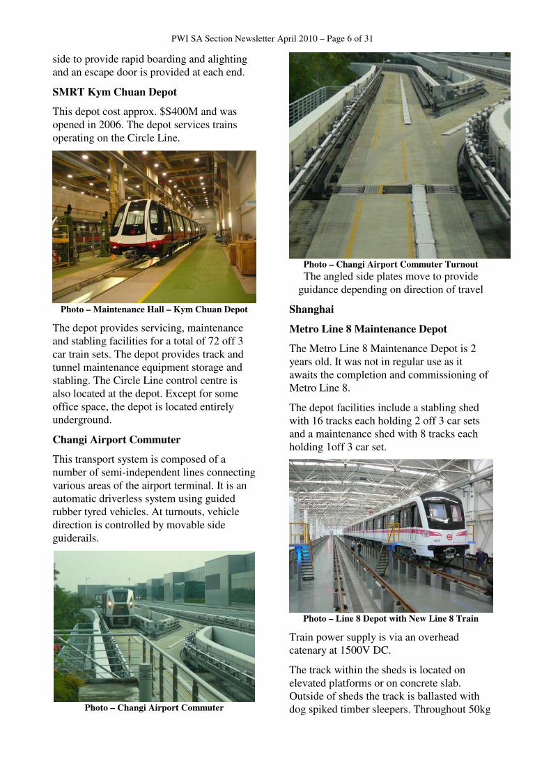
This transport system is composed of a number of semi-independent lines connecting various areas of the airport terminal. It is an automatic driverless system using guided rubber tyred vehicles. At turnouts, vehicle direction is controlled by movable side guiderails.
Photo – Changi Airport Commuter
Photo – Changi Airport Commuter Turnout
The angled side plates move to provide guidance depending on direction of travel
Shanghai
Metro Line 8 Maintenance Depot
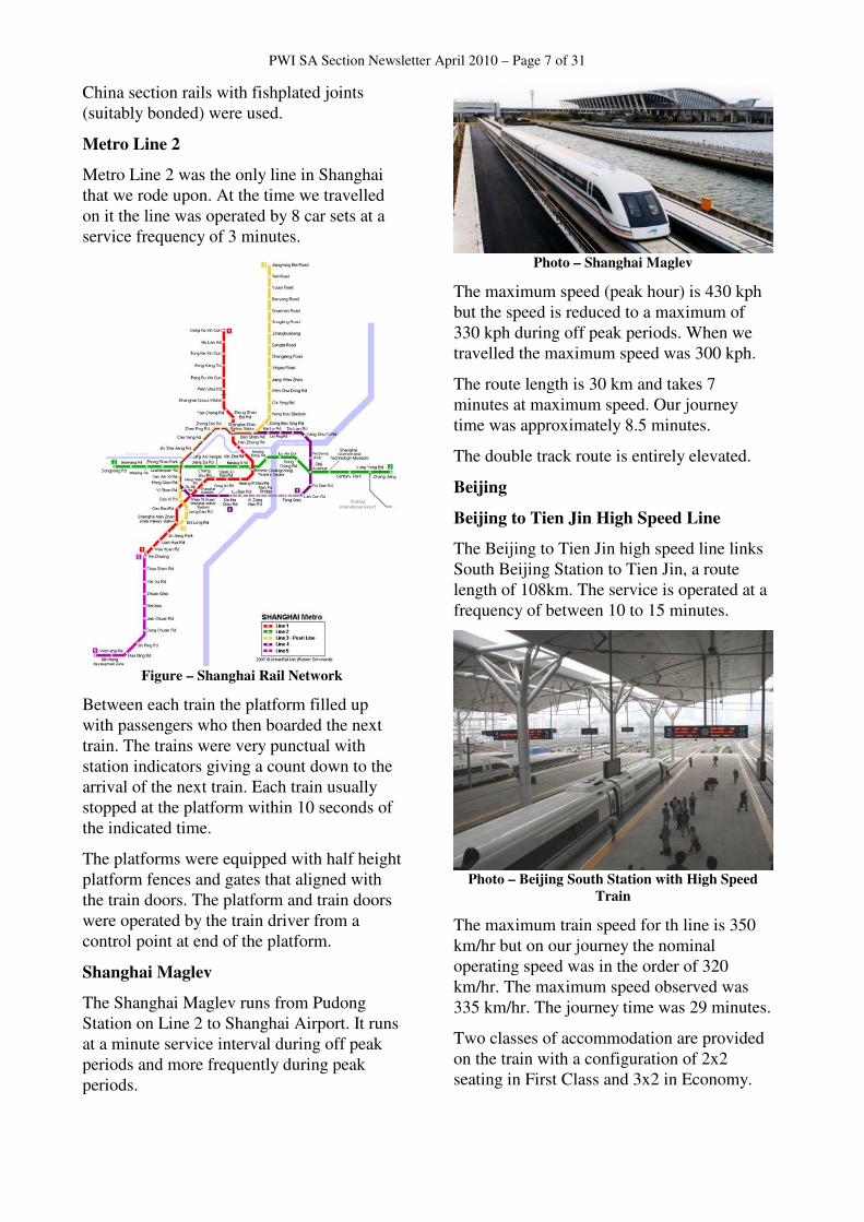
The Metro Line 8 Maintenance Depot is 2 years old. It was not in regular use as it awaits the completion and commissioning of Metro Line 8.
The depot facilities include a stabling shed with 16 tracks each holding 2 off 3 car sets and a maintenance shed with 8 tracks each holding 1off 3 car set.
Photo – Line 8 Depot with New Line 8 Train
Train power supply is via an overhead catenary at 1500V DC.
The track within the sheds is located on elevated platforms or on concrete slab. Outside of sheds the track is ballasted with dog spiked timber sleepers. Throughout 50kg
PWI SA Section Newsletter April 2010 – Page 7 of 31
China section rails with fishplated joints (suitably bonded) were used.
Metro Line 2
Metro Line 2 was the only line in Shanghai that we rode upon. At the time we travelled on it the line was operated by 8 car sets at a service frequency of 3 minutes.
Figure – Shanghai Rail Network
Between each train the platform filled up with passengers who then boarded the next train. The trains were very punctual with station indicators giving a count down to the arrival of the next train. Each train usually stopped at the platform within 10 seconds of the indicated time.
The platforms were equipped with half height platform fences and gates that aligned with the train doors. The platform and train doors were operated by the train driver from a control point at end of the platform.
Shanghai Maglev
The Shanghai Maglev runs from Pudong Station on Line 2 to Shanghai Airport. It runs at a minute service interval during off peak periods and more frequently during peak periods.
Photo – Shanghai Maglev
The maximum speed (peak hour) is 430 kph but the speed is reduced to a maximum of 330 kph during off peak periods. When we travelled the maximum speed was 300 kph.
The route length is 30 km and takes 7 minutes at maximum speed. Our journey time was approximately 8.5 minutes.
The double track route is entirely elevated.
Beijing
Beijing to Tien Jin High Speed Line
The Beijing to Tien Jin high speed line links South Beijing Station to Tien Jin, a route length of 108km. The service is operated at a frequency of between 10 to 15 minutes.
Photo – Beijing South Station with High Speed
Train
The maximum train speed for th line is 350 km/hr but on our journey the nominal operating speed was in the order of 320 km/hr. The maximum speed observed was 335 km/hr. The journey time was 29 minutes.
Two classes of accommodation are provided on the train with a configuration of 2x2 seating in First Class and 3x2 in Economy.
PWI SA Section Newsletter April 2010 – Page 8 of 31
Remarkably, the line appeared quite conventional with wheel on rail technology and standard overhead power supply.
Photo – Beijing to Tien Jin High Speed Trackwork
The vehicles for the high speed line are based on German ICE Train Sets. They are powered by a 25KV AC overhead and are designed for a maximum of 360 km/hr.
Photo – High Speed Train Approaching Tien Jin
Station
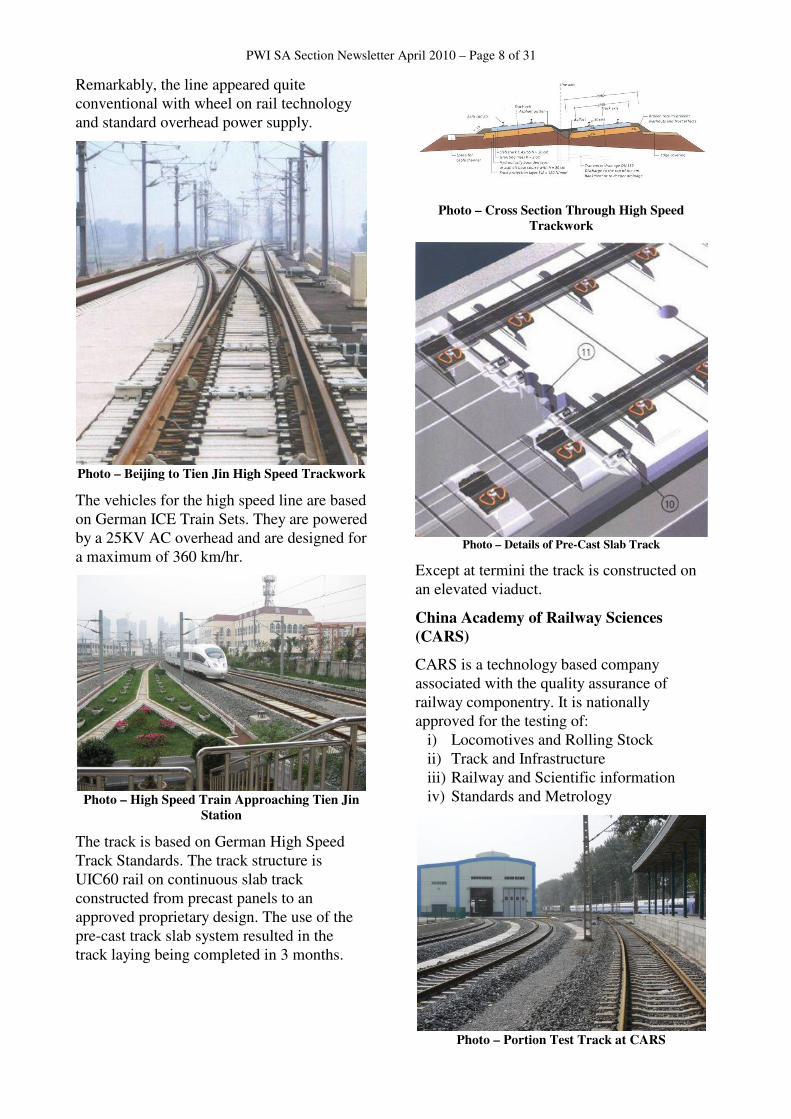
The track is based on German High Speed Track Standards. The track structure is UIC60 rail on continuous slab track constructed from precast panels to an approved proprietary design. The use of the pre-cast track slab system resulted in the track laying being completed in 3 months.
Photo – Cross Section Through High Speed
Trackwork
Photo – Details of Pre-Cast Slab Track
Except at termini the track is constructed on an elevated viaduct.
China Academy of Railway Sciences
(CARS)
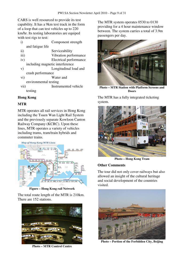
CARS is a technology based company associated with the quality assurance of railway componentry. It is nationally approved for the testing of:
i) Locomotives and Rolling Stock ii) Track and Infrastructure iii) Railway and Scientific information iv) Standards and Metrology
Photo – Portion Test Track at CARS
PWI SA Section Newsletter April 2010 – Page 9 of 31
CARS is well resourced to provide its test capability. It has a 9km test track in the form of a loop that can test vehicles up to 220 km/hr. Its testing laboratories are equiped with test rigs to test:
i) Component strength and fatigue life
ii) Serviceability iii) Vibration performance iv) Electrical performance
including magnetic interference v) Longitudinal load and
crash performance vi) Water and
environmental testing vii) Instrumented vehicle
testing
Hong Kong
MTR
MTR operates all rail services in Hong Kong including the Tsuen Wan Light Rail System and the previously separate Kowloon Canton Railway Company (KCRC). Upon these lines, MTR operates a variety of vehicles including trams, tram/train hybrids and commuter trains.
Figure – Hong Kong rail Network
The total route length of the MTR is 210km. There are 152 stations.
Photo – MTR Control Centre
The MTR system operates 0530 to 0130 providing for a 4 hour maintenance window between. The system carries a total of 3.9m passengers per day.
Photo – MTR Station with Platform Screens and
Doors
The MTR has a fully integrated ticketing system.
Photo – Hong Kong Tram
Other Comments
The tour did not only cover railways but also allowed an insight of the cultural heritage and social development of the countries visited.
Photo – Portion of the Forbidden City, Beijing
PWI SA Section Newsletter April 2010 – Page 10 of 31
Photo – China National Rail Museum
Max Shuard with Chairman Mao’s Locomotive
Photo – Max Shuard on the Great Wall
Observations and Learnings
Plan Ahead
Master planning of public transport systems should be based on long term horizons. Singapore has Land Transport Planning and Management horizons of 30 to 40 years. Most other cities appear to have similar planning horizons.
Design for the 30 Minute Rule
The 30 minute rule is a broad rule of thumb that says for a commuter type journey, most commuters generally accept a journey time on the system of up to 30 minutes. All systems observed, even though quite different in configuration or purpose, appeared to be designed to meet the 30 Minute Rule. In each case this was achieved by a suitable combination of:
i) Train speed ii) Station spacing iii) Route length
Examples of how the 30 minute rule was achieved are:
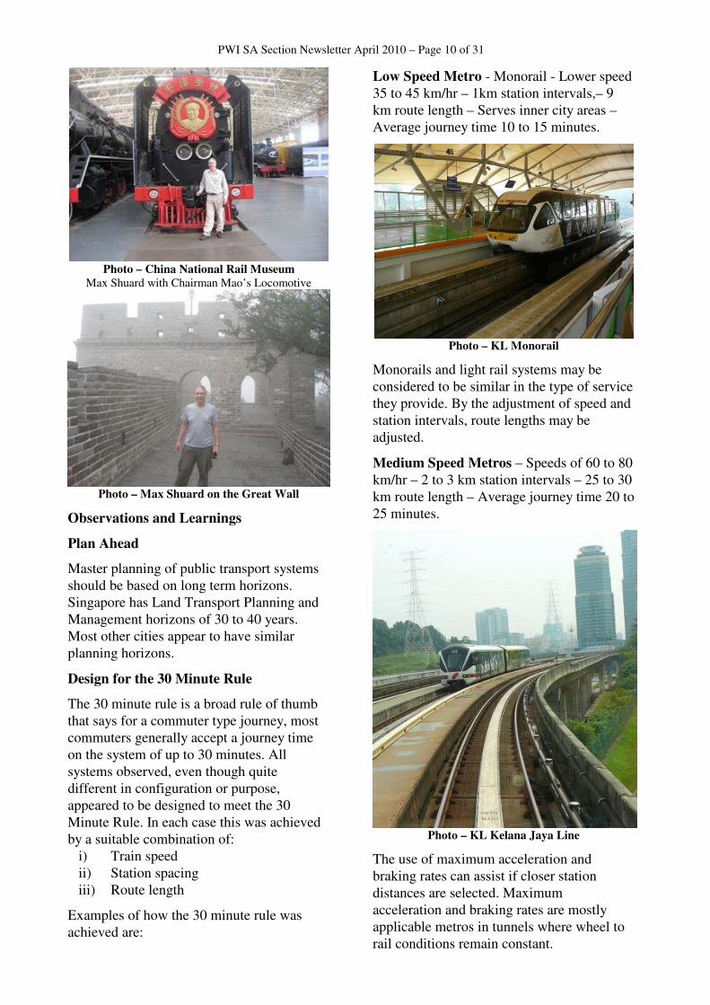
Low Speed Metro - Monorail - Lower speed 35 to 45 km/hr – 1km station intervals,– 9 km route length – Serves inner city areas – Average journey time 10 to 15 minutes.
Photo – KL Monorail
Monorails and light rail systems may be considered to be similar in the type of service they provide. By the adjustment of speed and station intervals, route lengths may be adjusted.
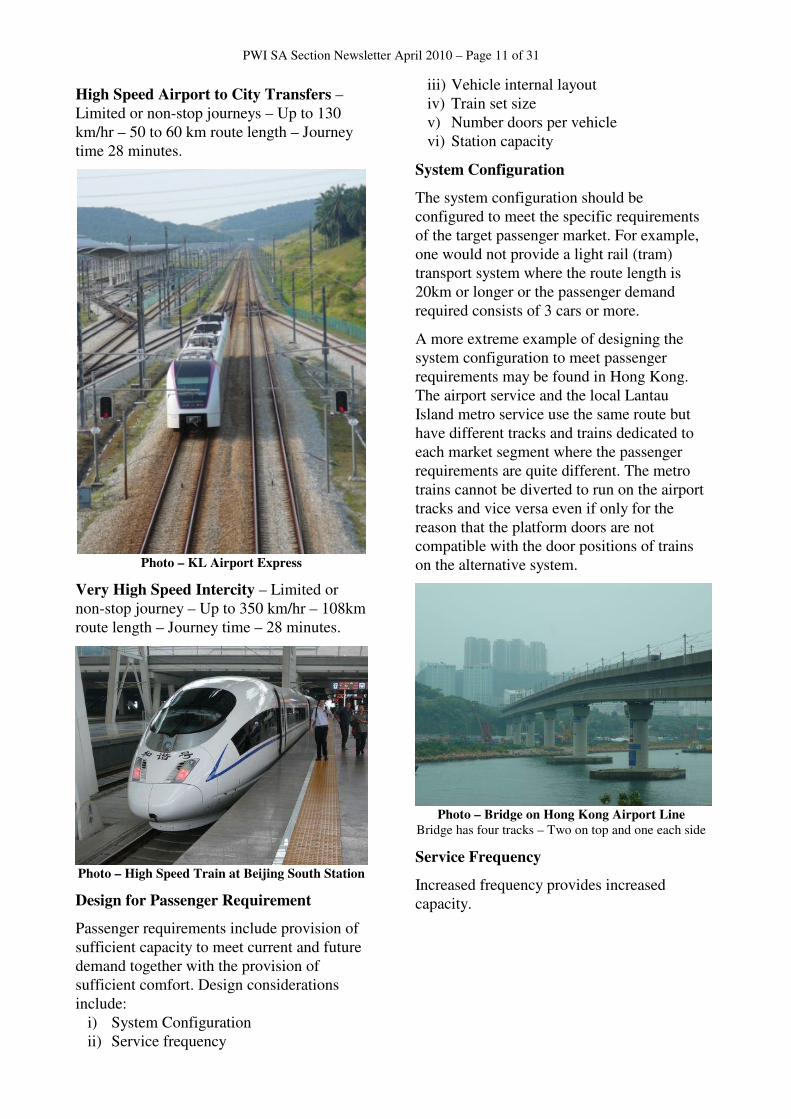
Medium Speed Metros – Speeds of 60 to 80 km/hr – 2 to 3 km station intervals – 25 to 30 km route length – Average journey time 20 to 25 minutes.
Photo – KL Kelana Jaya Line
The use of maximum acceleration and braking rates can assist if closer station distances are selected. Maximum acceleration and braking rates are mostly applicable metros in tunnels where wheel to rail conditions remain constant.
PWI SA Section Newsletter April 2010 – Page 11 of 31
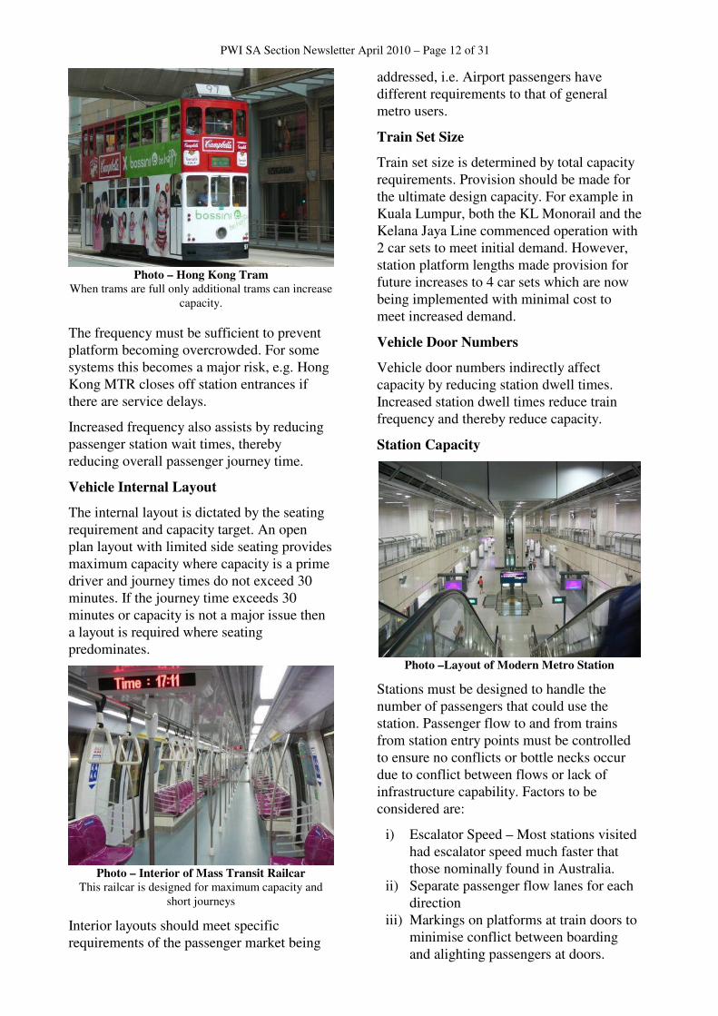
High Speed Airport to City Transfers – Limited or non-stop journeys – Up to 130 km/hr – 50 to 60 km route length – Journey time 28 minutes.
Photo – KL Airport Express
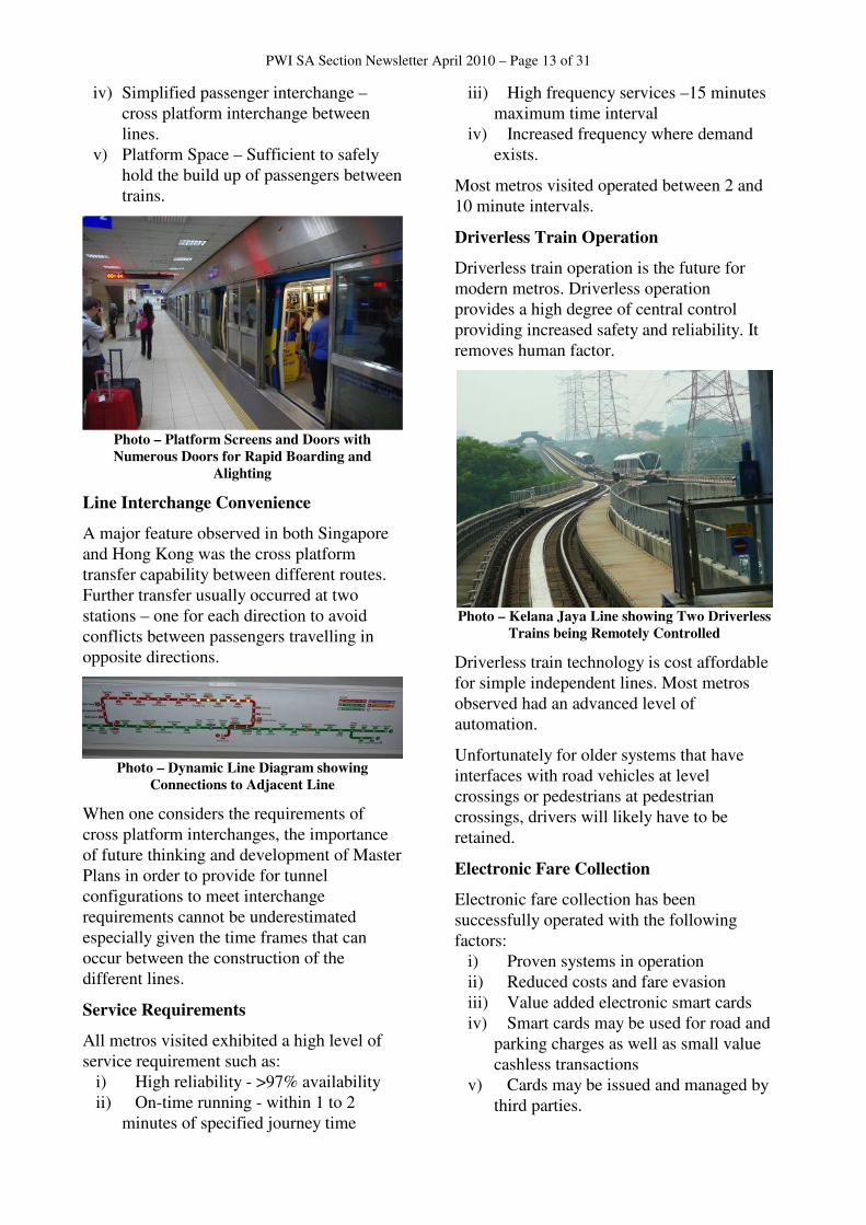
Very High Speed Intercity – Limited or non-stop journey – Up to 350 km/hr – 108km route length – Journey time – 28 minutes.
Photo – High Speed Train at Beijing South Station
Design for Passenger Requirement
Passenger requirements include provision of sufficient capacity to meet current and future demand together with the provision of sufficient comfort. Design considerations include:
i) System Configuration ii) Service frequency
iii) Vehicle internal layout iv) Train set size v) Number doors per vehicle vi) Station capacity
System Configuration
The system configuration should be configured to meet the specific requirements of the target passenger market. For example, one would not provide a light rail (tram) transport system where the route length is 20km or longer or the passenger demand required consists of 3 cars or more.
A more extreme example of designing the system configuration to meet passenger requirements may be found in Hong Kong. The airport service and the local Lantau Island metro service use the same route but have different tracks and trains dedicated to each market segment where the passenger requirements are quite different. The metro trains cannot be diverted to run on the airport tracks and vice versa even if only for the reason that the platform doors are not compatible with the door positions of trains on the alternative system.
Photo – Bridge on Hong Kong Airport Line
Bridge has four tracks – Two on top and one each side
Service Frequency
Increased frequency provides increased capacity.
PWI SA Section Newsletter April 2010 – Page 12 of 31
Photo – Hong Kong Tram
When trams are full only additional trams can increase capacity.
The frequency must be sufficient to prevent platform becoming overcrowded. For some systems this becomes a major risk, e.g. Hong Kong MTR closes off station entrances if there are service delays.
Increased frequency also assists by reducing passenger station wait times, thereby reducing overall passenger journey time.
Vehicle Internal Layout
The internal layout is dictated by the seating requirement and capacity target. An open plan layout with limited side seating provides maximum capacity where capacity is a prime driver and journey times do not exceed 30 minutes. If the journey time exceeds 30 minutes or capacity is not a major issue then a layout is required where seating predominates.
Photo – Interior of Mass Transit Railcar
This railcar is designed for maximum capacity and short journeys
Interior layouts should meet specific requirements of the passenger market being
addressed, i.e. Airport passengers have different requirements to that of general metro users.
Train Set Size
Train set size is determined by total capacity requirements. Provision should be made for the ultimate design capacity. For example in Kuala Lumpur, both the KL Monorail and the Kelana Jaya Line commenced operation with 2 car sets to meet initial demand. However, station platform lengths made provision for future increases to 4 car sets which are now being implemented with minimal cost to meet increased demand.
Vehicle Door Numbers
Vehicle door numbers indirectly affect capacity by reducing station dwell times. Increased station dwell times reduce train frequency and thereby reduce capacity.
Station Capacity
Photo –Layout of Modern Metro Station
Stations must be designed to handle the number of passengers that could use the station. Passenger flow to and from trains from station entry points must be controlled to ensure no conflicts or bottle necks occur due to conflict between flows or lack of infrastructure capability. Factors to be considered are:
i) Escalator Speed – Most stations visited had escalator speed much faster that those nominally found in Australia.
ii) Separate passenger flow lanes for each direction
iii) Markings on platforms at train doors to minimise conflict between boarding and alighting passengers at doors.
PWI SA Section Newsletter April 2010 – Page 13 of 31
iv) Simplified passenger interchange – cross platform interchange between lines.
v) Platform Space – Sufficient to safely hold the build up of passengers between trains.
Photo – Platform Screens and Doors with
Numerous Doors for Rapid Boarding and
Alighting
Line Interchange Convenience
A major feature observed in both Singapore and Hong Kong was the cross platform transfer capability between different routes. Further transfer usually occurred at two stations – one for each direction to avoid conflicts between passengers travelling in opposite directions.
Photo – Dynamic Line Diagram showing
Connections to Adjacent Line
When one considers the requirements of cross platform interchanges, the importance of future thinking and development of Master Plans in order to provide for tunnel configurations to meet interchange requirements cannot be underestimated especially given the time frames that can occur between the construction of the different lines.
Service Requirements
All metros visited exhibited a high level of service requirement such as:
i) High reliability - >97% availability ii) On-time running - within 1 to 2
minutes of specified journey time
iii) High frequency services –15 minutes maximum time interval
iv) Increased frequency where demand exists.
Most metros visited operated between 2 and 10 minute intervals.
Driverless Train Operation
Driverless train operation is the future for modern metros. Driverless operation provides a high degree of central control providing increased safety and reliability. It removes human factor.
Photo – Kelana Jaya Line showing Two Driverless
Trains being Remotely Controlled
Driverless train technology is cost affordable for simple independent lines. Most metros observed had an advanced level of automation.
Unfortunately for older systems that have interfaces with road vehicles at level crossings or pedestrians at pedestrian crossings, drivers will likely have to be retained.
Electronic Fare Collection
Electronic fare collection has been successfully operated with the following factors:
i) Proven systems in operation ii) Reduced costs and fare evasion iii) Value added electronic smart cards iv) Smart cards may be used for road and
parking charges as well as small value cashless transactions
v) Cards may be issued and managed by third parties.
PWI SA Section Newsletter April 2010 – Page 14 of 31
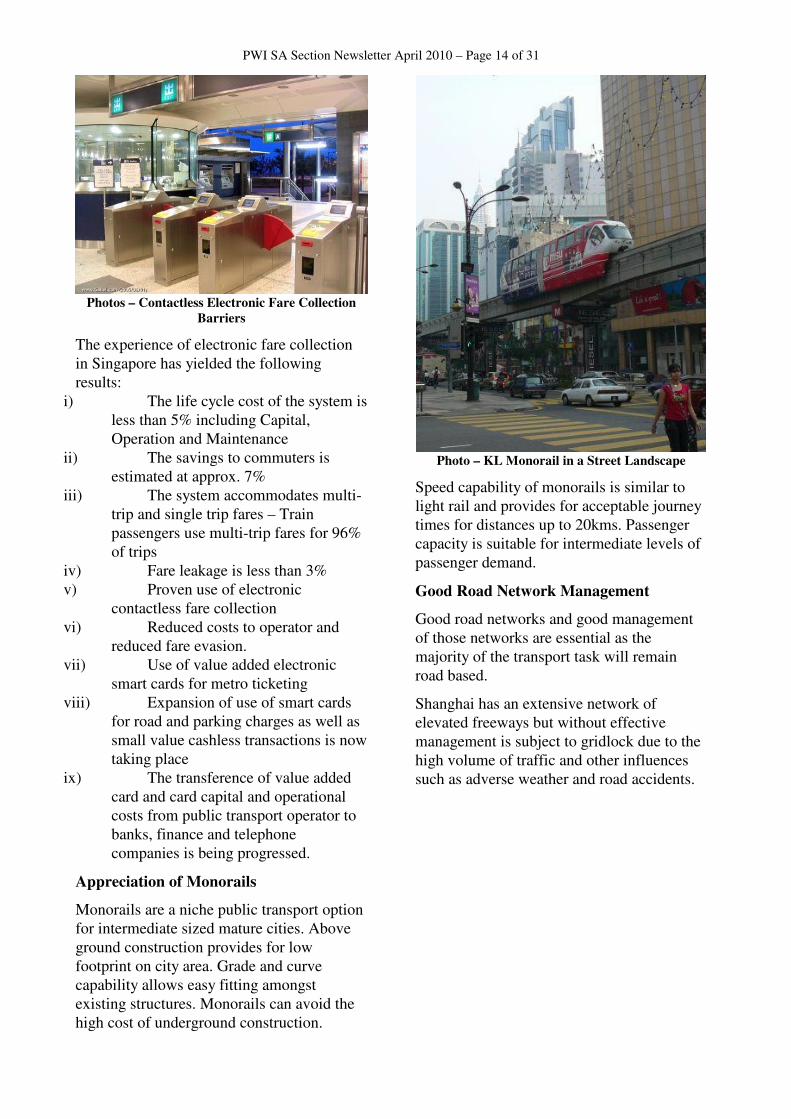
Photos – Contactless Electronic Fare Collection
Barriers
The experience of electronic fare collection in Singapore has yielded the following results:
i) The life cycle cost of the system is less than 5% including Capital, Operation and Maintenance
ii) The savings to commuters is estimated at approx. 7%
iii) The system accommodates multi-trip and single trip fares – Train passengers use multi-trip fares for 96% of trips
iv) Fare leakage is less than 3% v) Proven use of electronic
contactless fare collection vi) Reduced costs to operator and
reduced fare evasion. vii) Use of value added electronic
smart cards for metro ticketing viii) Expansion of use of smart cards
for road and parking charges as well as small value cashless transactions is now taking place
ix) The transference of value added card and card capital and operational costs from public transport operator to banks, finance and telephone companies is being progressed.
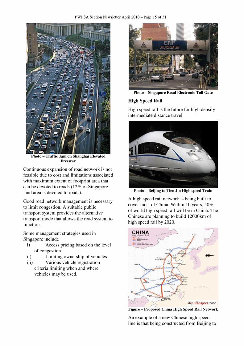
Appreciation of Monorails
Monorails are a niche public transport option for intermediate sized mature cities. Above ground construction provides for low footprint on city area. Grade and curve capability allows easy fitting amongst existing structures. Monorails can avoid the high cost of underground construction.
Photo – KL Monorail in a Street Landscape
Speed capability of monorails is similar to light rail and provides for acceptable journey times for distances up to 20kms. Passenger capacity is suitable for intermediate levels of passenger demand.
Good Road Network Management
Good road networks and good management of those networks are essential as the majority of the transport task will remain road based.
Shanghai has an extensive network of elevated freeways but without effective management is subject to gridlock due to the high volume of traffic and other influences such as adverse weather and road accidents.
PWI SA Section Newsletter April 2010 – Page 15 of 31
Photo – Traffic Jam on Shanghai Elevated
Freeway
Continuous expansion of road network is not feasible due to cost and limitations associated with maximum extent of footprint area that can be devoted to roads (12% of Singapore land area is devoted to roads).
Good road network management is necessary to limit congestion. A suitable public transport system provides the alternative transport mode that allows the road system to function.
Some management strategies used in Singapore include
i) Access pricing based on the level of congestion
ii) Limiting ownership of vehicles iii) Various vehicle registration
criteria limiting when and where vehicles may be used.
Photo – Singapore Road Electronic Toll Gate
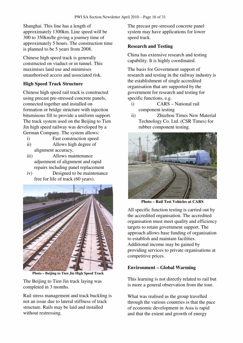
High Speed Rail
High speed rail is the future for high density intermediate distance travel.
Photo – Beijing to Tien Jin High speed Train
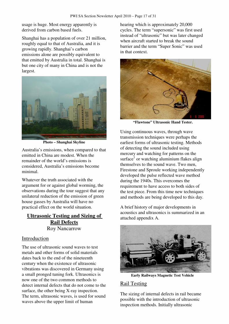
A high speed rail network is being built to cover most of China. Within 10 years, 50% of world high speed rail will be in China. The Chinese are planning to build 12000km of high speed rail by 2020.
Figure – Proposed China High Speed Rail Network
An example of a new Chinese high speed line is that being constructed from Beijing to
PWI SA Section Newsletter April 2010 – Page 16 of 31
Shanghai. This line has a length of approximately 1300km. Line speed will be 300 to 350km/hr giving a journey time of approximately 5 hours. The construction time is planned to be 5 years from 2008.
Chinese high speed track is generally constructed on viaduct or in tunnel. This maximises land use and minimises unauthorised access and associated risk.
High Speed Track Structure
Chinese high speed rail track is constructed using precast pre-stressed concrete panels, connected together and installed on formation or bridge structure with injection bituminous fill to provide a uniform support. The track system used on the Beijing to Tien Jin high speed railway was developed by a German Company. The system allows:
i) Fast construction speed ii) Allows high degree of
alignment accuracy, iii) Allows maintenance
adjustment of alignment and rapid repairs including panel replacement
iv) Designed to be maintenance free for life of track (60 years).
Photo – Beijing to Tien Jin High Speed Track
The Beijing to Tien Jin track laying was completed in 3 months.
Rail stress management and track buckling is not an issue due to lateral stiffness of track structure. Rails may be laid and installed without restressing.
The precast pre-stressed concrete panel system may have applications for lower speed track.
Research and Testing
China has extensive research and testing capability. It is highly coordinated.
The basis for Government support of research and testing in the railway industry is the establishment of single accredited organisation that are supported by the government for research and testing for specific functions, e.g.
i) CARS – National rail component testing
ii) Zhuzhou Times New Material Technology Co. Ltd. (CSR Times) for rubber component testing.
Photo – Rail Test Vehicles at CARS
All specific function testing is carried out by the accredited organisation. The accredited organisation must meet quality and efficiency targets to retain government support. The approach allows base funding of organisation to establish and maintain facilities. Additional income may be gained by providing services to private organisations at competitive prices.
Environment – Global Warming
This learning is not directly related to rail but is more a general observation from the tour. What was realised as the group travelled through the various countries is that the pace of economic development in Asia is rapid and that the extent and growth of energy
PWI SA Section Newsletter April 2010 – Page 17 of 31
usage is huge. Most energy apparently is derived from carbon based fuels.
Shanghai has a population of over 21 million, roughly equal to that of Australia, and it is growing rapidly. Shanghai’s carbon emissions alone are possibly equivalent to that emitted by Australia in total. Shanghai is but one city of many in China and is not the largest.
Photo – Shanghai Skyline
Australia’s emissions, when compared to that emitted in China are modest. When the remainder of the world’s emissions is considered, Australia’s emissions become minimal.
Whatever the truth associated with the argument for or against global worming, the observations during the tour suggest that any unilateral reduction of the emission of green house gasses by Australia will have no practical effect on the world situation.
Ultrasonic Testing and Sizing of
Rail Defects
Roy Nancarrow
Introduction
The use of ultrasonic sound waves to test metals and other forms of solid materials dates back to the end of the nineteenth century when the existence of ultrasonic vibrations was discovered in Germany using a small pronged tuning fork. Ultrasonics is now one of the two common methods to detect internal defects that do not come to the surface, the other being X-ray inspection. The term, ultrasonic waves, is used for sound waves above the upper limit of human
hearing which is approximately 20,000 cycles. The term “supersonic” was first used instead of “ultrasonic” but was later changed when aircraft started to break the sound barrier and the term “Super Sonic” was used in that context.
“Flawtone” Ultrasonic Hand Tester.
Using continuous waves, through wave transmission techniques were perhaps the earliest forms of ultrasonic testing. Methods of detecting the sound included using mercury and watching for patterns on the surface1 or watching aluminium flakes align themselves to the sound wave. Two men, Firestone and Sproule working independently developed the pulse reflected wave method during the 1940s. This overcomes the requirement to have access to both sides of the test piece. From this time new techniques and methods are being developed to this day.
A brief history of major developments in acoustics and ultrasonics is summarized in an attached appendix A.
Early Railways Magnetic Test Vehicle
Rail Testing
The sizing of internal defects in rail became possible with the introduction of ultrasonic inspection methods. Initially ultrasonic
PWI SA Section Newsletter April 2010 – Page 18 of 31
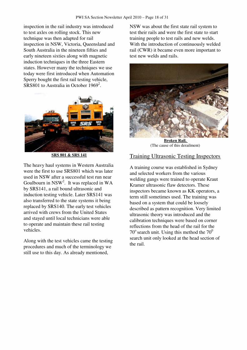
inspection in the rail industry was introduced to test axles on rolling stock. This new technique was then adapted for rail inspection in NSW, Victoria, Queensland and South Australia in the nineteen fifties and early nineteen sixties along with magnetic induction techniques in the three Eastern states. However many the techniques we use today were first introduced when Automation Sperry bought the first rail testing vehicle, SRS801 to Australia in October 19692.
SRS 801 & SRS 141
The heavy haul systems in Western Australia were the first to use SRS801 which was later used in NSW after a successful test run near Goulbourn in NSW2. It was replaced in WA by SRS141, a rail bound ultrasonic and induction testing vehicle. Later SRS141 was also transferred to the state systems it being replaced by SRS140. The early test vehicles arrived with crews from the United States and stayed until local technicians were able to operate and maintain these rail testing vehicles.
Along with the test vehicles came the testing procedures and much of the terminology we still use to this day. As already mentioned,
NSW was about the first state rail system to test their rails and were the first state to start training people to test rails and new welds. With the introduction of continuously welded rail (CWR) it became even more important to test new welds and rails.
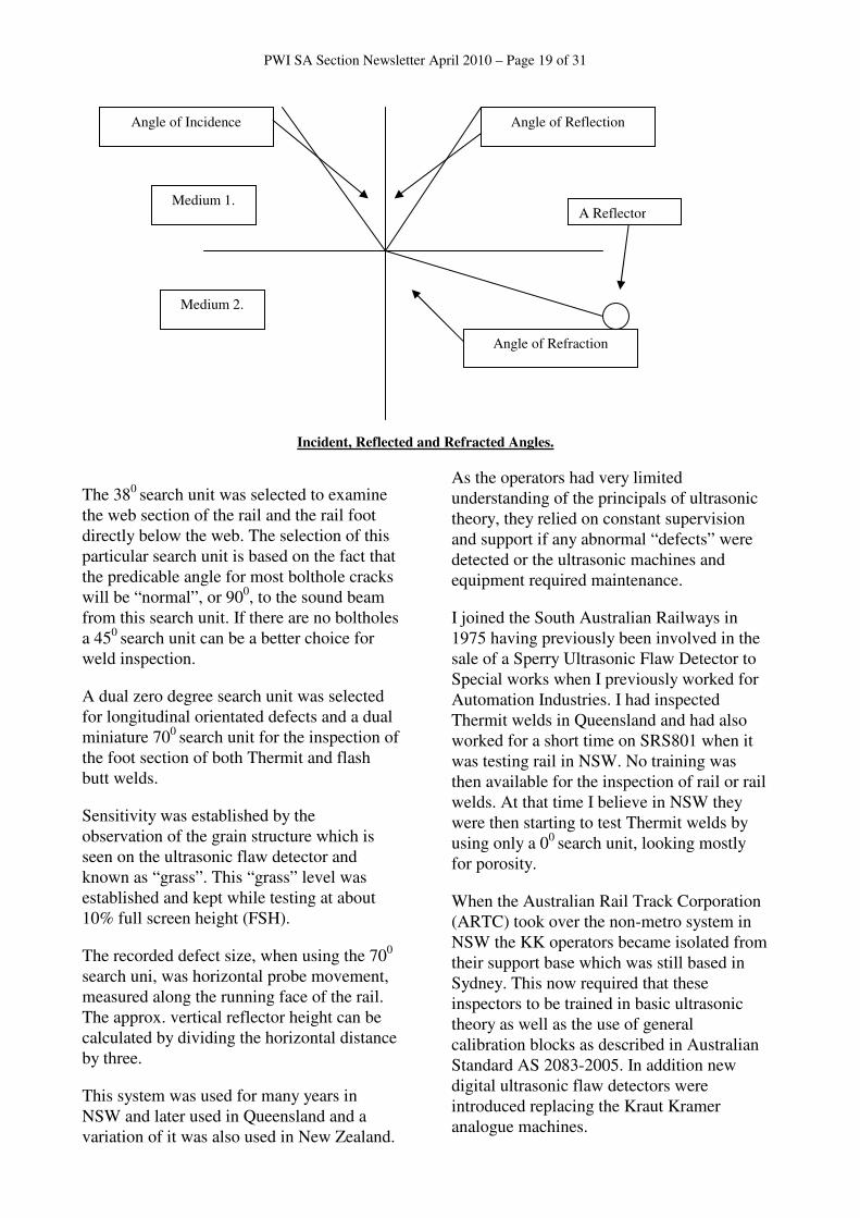
Broken Rail.
(The cause of this derailment)
Training Ultrasonic Testing Inspectors
A training course was established in Sydney and selected workers from the various welding gangs were trained to operate Kraut Kramer ultrasonic flaw detectors. These inspectors became known as KK operators, a term still sometimes used. The training was based on a system that could be loosely described as pattern recognition. Very limited ultrasonic theory was introduced and the calibration techniques were based on corner reflections from the head of the rail for the 70o search unit. Using this method the 700
search unit only looked at the head section of the rail.
PWI SA Section Newsletter April 2010 – Page 19 of 31
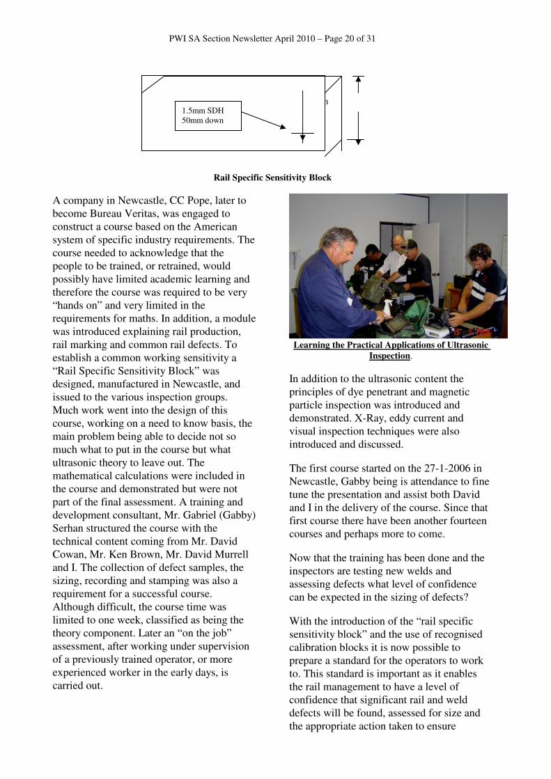
Incident, Reflected and Refracted Angles.
The 380 search unit was selected to examine the web section of the rail and the rail foot directly below the web. The selection of this particular search unit is based on the fact that the predicable angle for most bolthole cracks will be “normal”, or 900, to the sound beam from this search unit. If there are no boltholes a 450 search unit can be a better choice for weld inspection.
A dual zero degree search unit was selected for longitudinal orientated defects and a dual miniature 700 search unit for the inspection of the foot section of both Thermit and flash butt welds.
Sensitivity was established by the observation of the grain structure which is seen on the ultrasonic flaw detector and known as “grass”. This “grass” level was established and kept while testing at about 10% full screen height (FSH).
The recorded defect size, when using the 700
search uni, was horizontal probe movement, measured along the running face of the rail. The approx. vertical reflector height can be calculated by dividing the horizontal distance by three.
This system was used for many years in NSW and later used in Queensland and a variation of it was also used in New Zealand.
As the operators had very limited understanding of the principals of ultrasonic theory, they relied on constant supervision and support if any abnormal “defects” were detected or the ultrasonic machines and equipment required maintenance.
I joined the South Australian Railways in 1975 having previously been involved in the sale of a Sperry Ultrasonic Flaw Detector to Special works when I previously worked for Automation Industries. I had inspected Thermit welds in Queensland and had also worked for a short time on SRS801 when it was testing rail in NSW. No training was then available for the inspection of rail or rail welds. At that time I believe in NSW they were then starting to test Thermit welds by using only a 00 search unit, looking mostly for porosity.
When the Australian Rail Track Corporation (ARTC) took over the non-metro system in NSW the KK operators became isolated from their support base which was still based in Sydney. This now required that these inspectors to be trained in basic ultrasonic theory as well as the use of general calibration blocks as described in Australian Standard AS 2083-2005. In addition new digital ultrasonic flaw detectors were introduced replacing the Kraut Kramer analogue machines.
Angle of Incidence Angle of Reflection
Angle of Refraction
Medium 1.
Medium 2.
A Reflector
PWI SA Section Newsletter April 2010 – Page 20 of 31
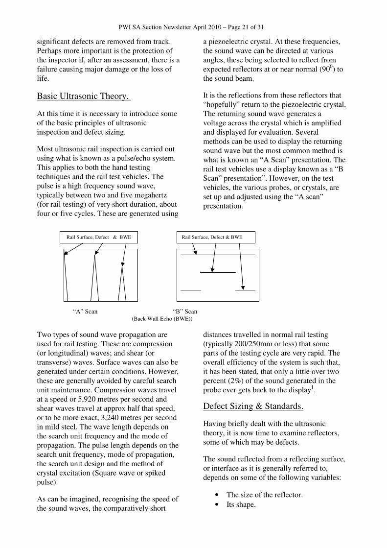
75mm
Rail Specific Sensitivity Block
A company in Newcastle, CC Pope, later to become Bureau Veritas, was engaged to construct a course based on the American system of specific industry requirements. The course needed to acknowledge that the people to be trained, or retrained, would possibly have limited academic learning and therefore the course was required to be very “hands on” and very limited in the requirements for maths. In addition, a module was introduced explaining rail production, rail marking and common rail defects. To establish a common working sensitivity a “Rail Specific Sensitivity Block” was designed, manufactured in Newcastle, and issued to the various inspection groups. Much work went into the design of this course, working on a need to know basis, the main problem being able to decide not so much what to put in the course but what ultrasonic theory to leave out. The mathematical calculations were included in the course and demonstrated but were not part of the final assessment. A training and development consultant, Mr. Gabriel (Gabby) Serhan structured the course with the technical content coming from Mr. David Cowan, Mr. Ken Brown, Mr. David Murrell and I. The collection of defect samples, the sizing, recording and stamping was also a requirement for a successful course. Although difficult, the course time was limited to one week, classified as being the theory component. Later an “on the job” assessment, after working under supervision of a previously trained operator, or more experienced worker in the early days, is carried out.
Learning the Practical Applications of Ultrasonic
Inspection.
In addition to the ultrasonic content the principles of dye penetrant and magnetic particle inspection was introduced and demonstrated. X-Ray, eddy current and visual inspection techniques were also introduced and discussed.
The first course started on the 27-1-2006 in Newcastle, Gabby being is attendance to fine tune the presentation and assist both David and I in the delivery of the course. Since that first course there have been another fourteen courses and perhaps more to come.
Now that the training has been done and the inspectors are testing new welds and assessing defects what level of confidence can be expected in the sizing of defects?
With the introduction of the “rail specific sensitivity block” and the use of recognised calibration blocks it is now possible to prepare a standard for the operators to work to. This standard is important as it enables the rail management to have a level of confidence that significant rail and weld defects will be found, assessed for size and the appropriate action taken to ensure
1.5mm SDH 50mm down
PWI SA Section Newsletter April 2010 – Page 21 of 31
significant defects are removed from track. Perhaps more important is the protection of the inspector if, after an assessment, there is a failure causing major damage or the loss of life.
Basic Ultrasonic Theory.
At this time it is necessary to introduce some of the basic principles of ultrasonic inspection and defect sizing.
Most ultrasonic rail inspection is carried out using what is known as a pulse/echo system. This applies to both the hand testing techniques and the rail test vehicles. The pulse is a high frequency sound wave, typically between two and five megahertz (for rail testing) of very short duration, about four or five cycles. These are generated using
a piezoelectric crystal. At these frequencies, the sound wave can be directed at various angles, these being selected to reflect from expected reflectors at or near normal (900) to the sound beam.
It is the reflections from these reflectors that “hopefully” return to the piezoelectric crystal. The returning sound wave generates a voltage across the crystal which is amplified and displayed for evaluation. Several methods can be used to display the returning sound wave but the most common method is what is known an “A Scan” presentation. The rail test vehicles use a display known as a “B Scan” presentation”. However, on the test vehicles, the various probes, or crystals, are set up and adjusted using the “A scan” presentation.
“A” Scan “B” Scan (Back Wall Echo (BWE))
Two types of sound wave propagation are used for rail testing. These are compression (or longitudinal) waves; and shear (or transverse) waves. Surface waves can also be generated under certain conditions. However, these are generally avoided by careful search unit maintenance. Compression waves travel at a speed or 5,920 metres per second and shear waves travel at approx half that speed, or to be more exact, 3,240 metres per second in mild steel. The wave length depends on the search unit frequency and the mode of propagation. The pulse length depends on the search unit frequency, mode of propagation, the search unit design and the method of crystal excitation (Square wave or spiked pulse).
As can be imagined, recognising the speed of the sound waves, the comparatively short
distances travelled in normal rail testing (typically 200/250mm or less) that some parts of the testing cycle are very rapid. The overall efficiency of the system is such that, it has been stated, that only a little over two percent (2%) of the sound generated in the probe ever gets back to the display1.
Defect Sizing & Standards.
Having briefly dealt with the ultrasonic theory, it is now time to examine reflectors, some of which may be defects.
The sound reflected from a reflecting surface, or interface as it is generally referred to, depends on some of the following variables:
• The size of the reflector.
• Its shape.
Rail Surface, Defect & BWE Rail Surface, Defect & BWE
PWI SA Section Newsletter April 2010 – Page 22 of 31
• The angle of the reflector to the ultrasonic wave.
• The reflecting surface profile.
• The surface condition of the rail.
• The shape of the rail surface compared to the shape of the sole on the search unit.
• The sound beam distance to (and from) the reflector.
• The grain structure of the parent material. (sound is scatted & absorbed; termed attenuation)
• The sound frequency being used.
• The dead zone, near zone & far zone of a particular search unit.
• Search unit damping & processing of the sound wave
• The rail temperature.
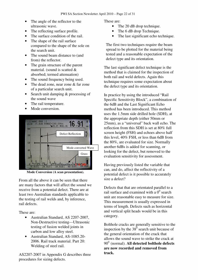
• Mode conversion.
Mode Conversion (A scan presentation).
From all the above it can be seen that there are many factors that will affect the sound we receive from a potential defect. There are at least two Australian standards applicable to the testing of rail welds and, by inference, rail defects.
These are:
• Australian Standard, AS 2207-2007, Non-Destructive testing—Ultrasonic testing of fusion welded joints in carbon and low alloy steel.
• Australian Standard, AS-1085.20-2006. Rail track material. Part 20: Welding of steel rail.
AS2207-2007 in Appendix G describes three procedures for sizing defects.
These are:
• The 20 dB drop technique.
• The 6 dB drop Technique.
• The last significant echo technique.
The first two techniques require the beam spread to be plotted for the material being tested and a reasonable expectation of the defect type and its orientation.
The last significant defect technique is the method that is claimed for the inspection of both rail and weld defects. Again this technique requires some expectation about the defect type and its orientation.
In practice by using the introduced “Rail Specific Sensitivity Block”, a combination of the 6dB and the Last Significant Echo method has been introduced. This method uses the 1.5mm side drilled hole (SDH), at the appropriate depth (either 50mm or 25mm), as a “universal” back wall echo. The reflection from this SDH is set at 80% full screen height (FSH) and echoes above half this level, 40% FSH, or less than 6dB from the 80%, are evaluated for size. Normally another 6dBs is added for scanning, or looking for the defect, but removed to the evaluation sensitivity for assessment.
Having previously listed the variable that can, and do, affect the reflectivity of a potential defect is it possible to accurately size a defect?
Defects that that are orientated parallel to a rail surface and examined with a 00 search unit are reasonable easy to measure for size. This measurement is usually expressed in terms of length. Defects such as horizontal and vertical split heads would be in this category.
Bolthole cracks are generally sensitive to the inspection by the 380 search unit because of the general orientation of the crack that allows the sound wave to strike the crack at
900 (normal). All detected bolthole defects
are now recorded and removed from
track.
Mode converted Wave
Defect Reflection
Grass
PWI SA Section Newsletter April 2010 – Page 23 of 31
Transverse vertical defects are far more difficult to size. By using the 700 search unit the best theoretical angle to strike the reflectors interface is 200 off the normal angle. AS-2207-2007 (page 10) states:
“1. Incident angles greater than 200 to the major expected reflector should not be used.”
As we are bound by Snell’s Law and critical angles, 700 is the best practical angle that can be used.
Fortunately many of the apparently negative aspects of the reflecting surfaces do assist in detecting and assisting in sizing defects.
Surfaced that are not mirror smooth tend to defuse (scatter) the sound beam thereby assisting in their detection.
Fatigue defects in rails and rail welds are seldom vertical, their orientation being dependant to the “more loaded” direction of traffic. They can be up to about 200 off the vertical making them ideal for detection with the 700 search unit, at least from one direction.
The use of the lower frequency search units, 2 MHz, (larger beam spread) assists in the detection of defects. Higher frequency search units, 5 MHz, may be better for sizing defects in some circumstances but are seldom used in the rail industry for this purpose.
A high level of accuracy when testing some defects is difficult. During the continuous testing of rail very limited time is allowed to carry out the test. The angles selected by the rail industry, 700, 380 (or 450) & 00 search units, does limit the angular response that may be achievable from some defects that are present in the rail or weld. This also applies to the test vehicle that has only one pass with the search units in a fixed position to detect a reflector.
Additional Techniques.
Advances in technology have improved some techniques and introduced some new methods that may be of some use for testing rail in the future.
Many new digital ultrasonic machines are now equipped with a digital generated form of Distance Amplitude Correction (DAC) and Time Variable Gain (TVG), also known as Time-corrected Gain. This technology allows for equal size reflectors at various depths to be displayed at a uniform height (TVG) or generates a curve to indicate the presence of equal size reflectors (DAC). Some older analogue machines were also equipped with this facility however it was difficult to use.
A system known as Phased Array Probe Technology is another interesting concept. This system allows the “steering” of the ultrasonic sound beam rather than having a number of fixed angle search unit. The display for this system is a form of “B” scan presentation.
Summary.
Years ago I introduced the phrase
“Ultrasonics doesn’t find defects, it finds
reflectors and some of these reflectors may
be defects”. Having previously listed a number of variables that will have an effect on the outcome of any ultrasonic test it can be seen that it is difficult to be precise when sizing some defects. It is however possible to
state, in general terms, whether a defect
reflection is small, medium or large, these categories being determined to some extent by the rail engineers or empirical knowledge. If some defects are to be left in track it is an advantage to record, in numerical terms the result of the ultrasonic test. This enables later inspections to determine if the defect is growing and may establish a time frame for
its removal, not necessarily based on the
apparent size of the defect.
Much progress has been made in the processing of the ultrasonic reflector in terms of processing speed, presentation and the recording of rail examinations. New techniques are being developed to enable the identification of various defects and comparisons made to defects of a similar type and size found on previous rail tests. An Australian company, Rail Test International
PWI SA Section Newsletter April 2010 – Page 24 of 31
(RTI) using modern communications, where available, allow for remote assessment of what the test vehicle has detected while the test is in progress and can, if necessary, alter the testing parameters of the test vehicle at that time.
In spite of all these advances, the basic
physics of introducing the sound into the
rail and the receiving of the reflection is
still the same. Hand testing or test vehicles
still need the sound to return (or reflect) to
identify and size defects.
References:
1. J. C. Drury, “Ultrasonic Flaw Detection for Technicians 3rd Edition”. 2. David Barnett, “History of Non-Destructive Testing in Australia”.
Appendix A.
The major developments in Acoustics and Ultrasonics are summarized below :
1822 Colladen used underwater bell to calculate the speed of sound in waters of Lake Geneva. 1830 Savart developed large, toothed wheel to generate very high frequencies. 1842 Magnetostrictive effect discovered by Joule. 1845 Stokes investigated effect of viscosity on attenuation. 1860 Tyndall developed the sensitive flame to detect high frequency waves. 1866 Kundt used dust figures in a tube to measure sound velocity. 1876 Galton invented the ultrasonic whistle. 1877 Rayleigh's "Theory of Sound" laid foundation for modern acoustics. 1880 Curie brothers discovered the piezoelectric effect. 1890 Koenig, studying audibility limits, produced vibrations up to 90,000 Hz. 1903 Lebedev and coworkers developed complete ultrasonic system to study absorption of waves. 1912 Sinking of Titanic led to proposals on use of acoustic waves to detect icebergs. 1912 Richardson files first patent for an underwater echo ranging sonar. 1914 Fessenden built first working sonar system in the United States which could detect icebergs two miles away. 1915 Langevin originated modern science of ultrasonics through work on the"Hydrophone" for submarine detection. 1921 Cady discovered the quartz stabilized
oscillator. 1922 Hartmann developed the air-jet ultrasonic generator. 1925 Pierce developed the ultrasonic interferometer. 1926 Boyle and Lehmann discovered the effect of bubbles and cavitation in liquids by ultrasound. 1927 Wood and Loomis described effects of intense ultrasound. 1928 Pierce developed the magnetostrictive transducer. 1928 Herzfeld and Rice developed molecular theory for dispersion and absorption of sound in gases. 1928 Sokolov proposed use of ultrasound for flaw detection. 1930 Debye and Sears and Lucas and Biquard discover diffraction of light by ultrasound. 1930 Harvey reported on the physical, chemical, and biological effects of ultrasound in macromolecules, microorganisms and cells. 1931 Mulhauser obtained a patent for using two ultrasonic transducers to detect flaws in solids. 1937 Sokolov invented an ultrasonic image tube. 1938 Pierce and Griffin detect the ultrasonic cries of bats. 1939 Pohlman investigated the therapeutic uses of ultrasonics. 1940 Firestone, in the United States and Sproule, in Britain, discovered ultrasonic pulse-echo metal-flaw detection. 1940 Sonar extensively developed and used to detect submarines.
9140 Flaw detecting device and measuring instrument 1941 "Reflectoscopes" extensively developed for non-destructive metal testing. 1942 Dussik brothers made first attempt at medical imaging with ultrasound. 1943 Resonance inspection method. 1944 Lynn and Putnam successfully used ultrasound waves to destroy brain tissue of animals. 1945 Newer piezoelectric ceramics such as barium titanate discovered. 1945 Supersonic reflectoscope, an instrument for inspecting the interior of solid parts by means of sound waves. 1945 Start of the development of power ultrasonic processes. 1948 Start of extensive study of ultrasonic medical imaging in the United States and Japan. 1954 Jaffe discovered the new piezoelectric ceramics lead titanate-zirconate.
Referenced in part from: Karl F. Graff, A History of Ultrasonics, in Physical Acoustics, Volume XV (Academic Press, New York, 1982), and Course notes, "An Introduction to Ultrasonics" by Peter B. Nagy, Department of Aerospace Engineering & Engineering Mechanics, University
PWI SA Section Newsletter April 2010 – Page 25 of 31
of Cincinnati, 2001, and "Assessing the Risks for Modern Diagnostic Ultrasound Imaging" by William D. O’Brien, Jr., Bioacoustics Research Laboratory, Department of Electrical and Computer Engineering, University of Illinois, 1997.
Adelaide Rail Upgrade Status
New Trams – The last of the 6 Citidis trams was delivered in the second week of February. All are now in service.
Glengowrie Tram Depot Upgrade – New trackwork at the rear of the depot to accommodate the additional trams is progressing and is expected to be operational early April. Trackwork renewal at the front of the depot will then be carried out in stages to minimise disruption to tram services. Alterations within the tram barn to allow maintenance of the various types of trams and the provision of an automatic tram wash and a separate paint booth will also be progressed over the next few months.
A new operations building will be constructed later this year.
South Road Tram Overpass – This project is rapidly approaching completion with the platform being reopened on Monday 15 March and the shared pathway being opened on the 19th March.
Tramline Extension to AEC – The trackwork for the tramline extension was completed and handed over for operations on Sunday 7 March. Formal extension of tram services to the AEC occurred on the 22nd March.
Station Upgrades – The upgrade of selected stations commenced on 18 January with the closure of the Hallet Cove Station. The upgrade of Hallett Cove Station will include:
i) An architecturally designed canopy shelter
ii) A platform realignment (to reduce height and distance gaps between platform and trains)
iii) Installation of access ramps and handrails
iv) Improved lighting and Closed Circuit Television (CCTV) security systems
v) Improved walking and cycling links with the stations
vi) Enhanced landscaping vii) Provision of additional car parking at
the stations Following the completion of the upgrade to Hallet Cove Station it is proposed to upgrade Hallett Cove Beach Station in a similar manner.
Port Adelaide Viaduct Upgrade – This project is progressing rapidly. New prestressed concrete beams have replaced the majority of the transom decks.
Steelwork repair and painting of the station viaduct and Commercial Road sections is nearing completion. Lipson Street Bridge painting and steelwork repair has been completed.
Work to upgrade the station platforms has started as has the laying of new track from the Adelaide end.
The Outer Harbor Line is planned to reopen on the 2nd May.
Rail Car Depot Relocation – The main buildings for the new Dry Creek Rail Car Depot are progressing. Installation of the depot trackwork has commenced. Completion and handover of the depot is planned for August/September this year.
Membership
Life Members
Life Membership is awarded to members who have provided outstanding support and contribution to the PWI. Our current Life Members are John Adams and Stephen Townsend.
Corporate Membership
Our Corporate Members for 2010 are:
i) Pandrol Australia
ii) John Holland
iii) OneSteel
iv) Transfield Services
v) TransAdelaide
vi) ARTC
vii) Southern Quarries
PWI SA Section Newsletter April 2010 – Page 26 of 31
viii) Phoenix Project Management
ix) Momentum Rail
Personal Membership
Personal Membership of the PWI SA Section is available to any person who is involved or interested in the rail industry.
For any non-members reading this Newsletter, we encouraged you to join. The cost is not great, we believe that the PWI provides valuable support to those in the rail industry and membership is a statement of support for both the PWI and the rail industry.
Personal membership application forms may be obtained from the Secretary.
Trackwork Achievement Award
The Trackwork Achievement Award is made on projects that involve or are associated with track or related infrastructure. It is disappointing to report that in 2009 no submissions were received.
The award this year comprises the retention of the Bert Rex Shield for one year and a cheque for the sum of $500.00.
The Trackwork Achievement Award is proudly sponsored by:
The PWI South Australian Section
acknowledges and thanks Rex-Lok for their continued support with this award.
OneSteel Safety Award
The OneSteel Safety Award shall be awarded by the PWI South Australian Section for commendable achievement and/or initiative in the field of occupational health, safety and welfare in relation to the Permanent Way of an operating railway.
It is disappointing to report that in 2009 no submissions were received. The award comprises a suitably engraved plaque and a cheque for the sum of $500.00.
The PWI South Australian Section
acknowledges and thanks OneSteel for their continued support with this award.
Articles and Papers for the PWI
Newsletter
Members and readers are encouraged to submit articles and papers on activities and technical issues related to the permanent way and railways in general.
Letters to the Editor
None received but letters from members would be most welcome.
British Railway Track and Track
Compendium
The “British Railway Track” book is currently being revised and the Seventh Edition will be published in future as a series of volumes, each to be purchased separately. The following volumes are currently available:
Volume 1 Design Part 3 – Bull Head Rail Volume 4 - Plain Line Maintenance Volume 5 – Switch and Crossing
Maintenance. Volume 9 – Track Terminology
Copies of the 6th Edition are still be available from the UK.
For further details as to how to obtain any of these books, please contact the Secretary.
2010 Membership Fees
Membership Fees for the 2010 Financial Year became due on the 1st November 2009.
Membership Fees for the 2010 Financial Year remain the same as last year and are:
Personal Member – City Location $25.00
Per. Member – Country Location $10.00
Corporate Member $500.00
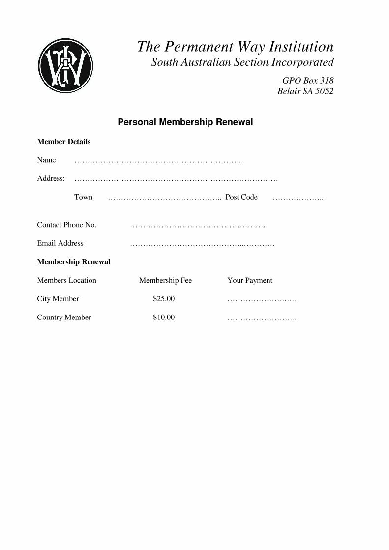
Membership renewal forms have been sent out separately by the Treasurer. Please return promptly with your payment. If you have misplaced the renewal notice, a membership renewal for is attached to the Newsletter.
PWI SA Section Newsletter April 2010 – Page 27 of 31
City Members are those residing in the Adelaide metropolitan area and Country Members are those residing outside the Adelaide metropolitan area.
Members are reminded that members become non-financial if Membership Fees are overdue by more than 6 months (i.e. 1st May) and that membership is automatically terminated if Fees are overdue by more than 18 months.
It is the member’s responsibility to advise the Secretary of any change of address or other contact details.
PWI 2010 Journals
Orders for 2010 Journals are now closed. Orders for 2011 Journals may be placed from November 2010. The Part 1 2010 Journal has now been received and sent to those members who have ordered them. The main articles in the Journal are:
i) A Mobile Flashbutt Welding Perspective on the Stirling-Alloa-Kincardine Project – John Oates gives an overview of the
processes and requirements of the Mobile Flashbutt Welder currently owned and maintained by Babcock Rail and explains how the Stirling-Alloa-Kincardine Project benefited from its use.
ii) Solving the Capacity Challenges – Chris Parker reports on the seminar organised by the PWI on behalf of the Railway Engineers Forum held 29th October 2009.
iii) Mechanical Marvels – Phil Kirkland describes the recent and highly successful mechanised maintenance campaign for the Tyne and Wear Metro.
iv) Newport Area Signalling Renewal Severn Tunnel Junction Remodelling – Jeremy Reece outlines some of the complexities of the NASR project and explains how the remodelling of the track at Severn Tunnel Junction has been planned. He also looks in some detail at the NR60 S&C being installed in this project.
v) An Innovative Transition Structure – Dermot Kelly and Alan Whiteland describe how an innovative and cost effective solution was designed and delivered for transitions on to and off a slab track system.
PWI SA Section Newsletter April 2010 – Page 28 of 31
Contact with PWI South Australian Section Inc.
Should members wish to contact the PWI SA Section for any reason, please contact the Secretary - Stephen Townsend on 0400 135 481 during working hours or, if more convenient, any of the Committee members.
Contact details for the 20010 Committee are as follows:
Position Name Phone No. Email Address Chairman Harry Olsen 8344 0151 [email protected] Secretary Stephen Townsend 0400 135 481 [email protected] Treasurer Neil Orange 8217 4331 [email protected] Programme Director Stuart Glynn 8343 5524 [email protected] Committee Members Roger Wyatt 8344 6939 [email protected] Matthew Hart 8217 4260 [email protected] Roderick Taylor John Dring 8294 0384 [email protected]
Vice President John Adams 8295 5640 [email protected]
Notice of Committee Meeting
Committee members please note that the next Committee Meeting will be held on: Tuesday 6th April 2010,
at TransAdelaide, 71 Richmond Road, Mile End commencing at 4.30 pm.
Notice
This Newsletter is published by the PWI South Australian Section Inc. All correspondence, corrections or queries relating to the Newsletter should be address to the Secretary, PWI South Australian Section Inc., GPO Box 318,
Belair, SA 5052.
Disclaimer
Any statement or opinion in this document is offered in good faith based upon information supplied. However, no responsibility or liability is accepted by the Permanent Way Institution, South Australian Section Inc., or its members for or in respect of any statement or opinion in this document, irrespective of how or whether that
statement or opinion may be relied or acted upon.
The Permanent Way Institution South Australian Section Incorporated
GPO Box 318
Belair SA 5052
Personal Membership Renewal
Member Details
Name ………………………………………………………. Address: …………………………………………………………………… Town …………………………………….. Post Code ……………….. Contact Phone No. ……………………………………………. Email Address ……………………………………..…………
Membership Renewal
Members Location Membership Fee Your Payment City Member $25.00 ………………….….. Country Member $10.00 ……………………...
The Permanent Way Institution South Australian Section Incorporated
PO Box 318
Belair SA 5052
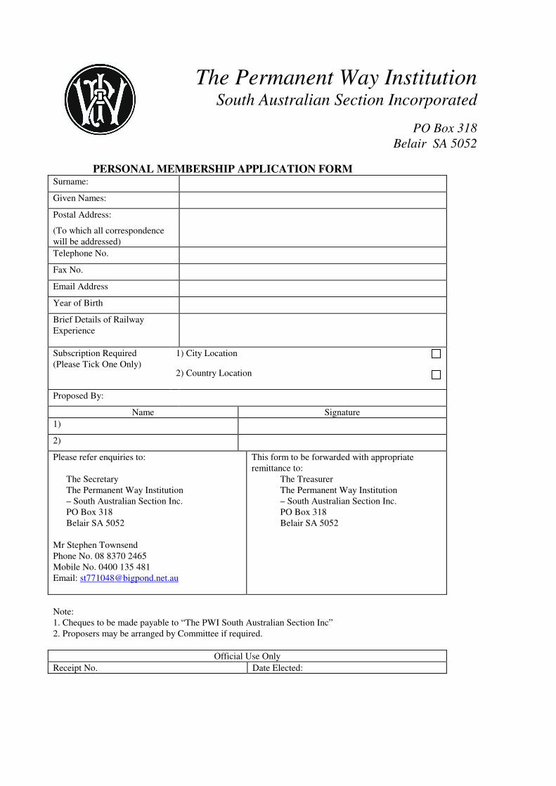
PERSONAL MEMBERSHIP APPLICATION FORM Surname:
Given Names:
Postal Address:
(To which all correspondence will be addressed)
Telephone No.
Fax No.
Email Address
Year of Birth
Brief Details of Railway Experience
Subscription Required (Please Tick One Only)
1) City Location
2) Country Location
Proposed By:
Name Signature
1)
2)
Please refer enquiries to:
The Secretary The Permanent Way Institution – South Australian Section Inc. PO Box 318 Belair SA 5052
Mr Stephen Townsend Phone No. 08 8370 2465 Mobile No. 0400 135 481 Email: [email protected]
This form to be forwarded with appropriate remittance to:
The Treasurer The Permanent Way Institution – South Australian Section Inc. PO Box 318 Belair SA 5052
Note: 1. Cheques to be made payable to “The PWI South Australian Section Inc” 2. Proposers may be arranged by Committee if required.
Official Use Only
Receipt No. Date Elected:
The Permanent Way Institution South Australian Section Incorporated
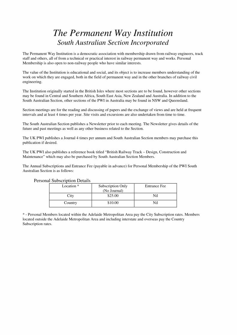
The Permanent Way Institution is a democratic association with membership drawn from railway engineers, track staff and others, all of from a technical or practical interest in railway permanent way and works. Personal Membership is also open to non-railway people who have similar interests. The value of the Institution is educational and social, and its object is to increase members understanding of the work on which they are engaged, both in the field of permanent way and in the other branches of railway civil engineering. The Institution originally started in the British Isles where most sections are to be found, however other sections may be found in Central and Southern Africa, South East Asia, New Zealand and Australia. In addition to the South Australian Section, other sections of the PWI in Australia may be found in NSW and Queensland. Section meetings are for the reading and discussing of papers and the exchange of views and are held at frequent intervals and at least 4 times per year. Site visits and excursions are also undertaken from time to time. The South Australian Section publishes a Newsletter prior to each meeting. The Newsletter gives details of the future and past meetings as well as any other business related to the Section. The UK PWI publishes a Journal 4 times per annum and South Australian Section members may purchase this publication if desired. The UK PWI also publishes a reference book titled “British Railway Track – Design, Construction and Maintenance” which may also be purchased by South Australian Section Members. The Annual Subscriptions and Entrance Fee (payable in advance) for Personal Membership of the PWI South Australian Section is as follows:
Personal Subscription Details Location * Subscription Only
(No Journal) Entrance Fee
City $25.00 Nil
Country $10.00 Nil
* - Personal Members located within the Adelaide Metropolitan Area pay the City Subscription rates. Members located outside the Adelaide Metropolitan Area and including interstate and overseas pay the Country Subscription rates.