2009 - idaho state tax commission - idaho.gov
TRANSCRIPT

Progress In Electromagnetics Research, Vol. 130, 347–368, 2012
SYSTEM-ON-CHIP 36.8 GHz RADIOMETER FOR SPACE-BASED OBSERVATION OF SOLAR FLARES: FEASIBIL-ITY STUDY IN 0.25 µm SiGe BiCMOS TECHNOLOGY
L. Aluigi1, L. Roselli1, S. M. White2, and F. Alimenti1, *
1Department of Electronic and Information Engineering (DIEI),University of Perugia, Via Duranti 93, Perugia 06125, Italy2Space Vehicles Directorate, AFRL, Kirtland AFB 87117, USA
Abstract—This paper deals with a feasibility study for a System-on-Chip (SoC) mm-wave radiometer devoted to space-based observationof solar flares and operating in the Ka-band. The radiometer has beendesigned in 250 nm SiGe BiCMOS process. The circuit integrates athree stages differential LNA with 37.2 dB gain and 4.8 dB noise figureat 36.8 GHz and a differential square-law detector based on HBTs,featuring a 96 mV/µW responsivity. The full radiometer achieves,potentially, a NETD of 0.1 K for 1 s integration time in Dicke mode.This work represents the first study of such an integrated instrumentfor Ka-band space-based observation of solar flares.
1. INTRODUCTION
The Sun is currently running through its maximum, the phase of mostintense activity which occurs once every 11 years. During this period,it erupts violently, emitting solar flares or throwing out coronal massejections (CMEs) consisting of billions of tons of charged particles.These events can trigger geomagnetic storms on Earth that could poseextraordinary risk to our critical systems and even our way of life [1].
As the human infrastructure has greatly expanded and grownmore complex, now more than ever, it is important to study andinvestigate the events as solar flares in order to prevent possible risksassociated with massive geomagnetic storms.
Millimeter-wave (mm-wave) radiometers are commonly employedin ground- and space-based scientific experiments ranging fromthe observation of the Earth’s atmosphere, forest-fire detection
Received 11 June 2012, Accepted 20 July 2012, Scheduled 17 August 2012* Corresponding author: Federico Alimenti ([email protected]).
348 Aluigi et al.
and oceanographic studies, to radio-astronomic experiments suchas the measurement of the Cosmic Microwave Background [2–4].Space agencies are showing a great interest in the development ofminiaturized instruments in such a way as to meet the missionconstraints imposed by the adoption on micro- and nano-satellites [5].Millimeter-wave receiver front-ends for radiometric imaging are underdevelopment mainly exploiting CMOS SiGe BiCMOS or GaAsPHEMT processes [6–8]. However, the cited designs are only focusedon ground-based applications such as imaging for security scannersand material analysis. In parallel, several mm-wave square-law powerdetectors have been published, showing that the integration of thisfundamental building block is possible either with SiGe BiCMOS [9, 10]or with CMOS [11]. As a consequence of the high scientific andindustrial interest around the passive mm-wave imaging, the first SoCmm-wave passive receiver on silicon has been published at the endof the year 2010 [12]. This integrated circuit is based on a 65 nmCMOS technology and exploits a direct amplification receiver. Theradiometer is equipped with an on-chip square-law detector and withan input Dicke switch for the receiver calibration.
The previous survey of the state-of-the-art shows that, until today,the design of a mm-wave radiometer for space-based applicationsexploiting a single silicon chip, is a completely original idea. Indeed allthe cited prototypes are not suited for space mainly because they donot use space-qualified processes. The space-qualification of a 250 nmSiGe BiCMOS technology, however, is currently under development bya European foundry, the IHP at Frankfurt-Oder, Germany [13].
In this paper, two very innovative concepts will be developed.First it will be shown that solar flares could be detected and measuredin the mm-wave frequency range from a space-based platform [14].This methodology has never been attempted before, and allowsus to reach a sensitivity much higher than that of conventionalground-based experiments. Second, it will be demonstrated that theabove observations could be carried-out with a novel instrument: asilicon System-on-Chip (SoC) mm-wave radiometer. Working withSoC instruments will significantly reduce weight, size and powerconsumption, all variables of extreme importance in space applications.In addition, the SoC implementation will allow unprecedentedinstrumental performance. One of the major technological challengesin the realization of millimeter-wave radiometers, in-fact, is the long-term stability of the receiver parameters such as, for example, thegain and the noise figure. High parametric stability can be achievedby maintaining at constant temperature a single chip of few squaremillimeters (the one containing the radiometer) with a remarkable

Progress In Electromagnetics Research, Vol. 130, 2012 349
save of power consumption. This latter aspect can also solve manyproblems related to operational conditions of the satellites, as hugetemperature variations occur during the transition from night to dayalong the orbital progression and significant thermal gradients withinthe satellite itself.
The feasibility study will be carried-out starting from thecharacteristics of solar flares (solar flare flux density) and will bedeveloped by describing the miniaturized instrument at both system-and transistor-levels. The paper is organized as follows. The scientificbackground of solar flares observation is given in Section 2. Section 3describes the system design details. Section 4 illustrates the building-blocks design details, while Section 5 discusses the simulated resultsfor the designed radiometer.
2. SCIENTIFIC BACKGROUND
Solar flares are a sudden release of a great amount of energy stored ashigh magnetic fields in solar active regions. Lasting minutes to hours,they are sources of radiation and particles. The magnetic energy israpidly converted into thermal, kinetic and mechanical energies andthe consequence is that the local plasma is heated to several tens ofmillions degrees, while particles are accelerated up to high energies.Flares are unique for the diversity of emission mechanism they exhibitand the broad range of wavelengths at which they radiate: from radio-wave, millimeter-wave, soft and hard-X rays, up to γ-rays with energiesreaching 1Gev [15, 16].
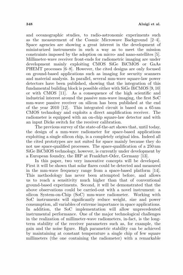
Millimeter-wave observations are the most sensitive tool to studythe highest energy (i.e., > 1Mev) electrons accelerated in solarflares [17]. Fig. 1 shows the effect of MeV-energy electrons on theradio spectrum of a solar flare. The solid line is the calculated spectrumemitted by electrons in a power-law distribution of energy with spectralindex −3.6, extending from 20 keV to 20 MeV in a constant magneticfield of 600 G. The dashed curve, instead, is the spectrum emittedby the same electron energy distribution but extending only from 20to 300 keV. When the MeV-energy electrons are absent, emission atmillimeter wavelengths is reduced by orders of magnitude whereasmicrowave emission is not greatly changed. At low frequencies discreteharmonics are seen in the model due to the unrealistic assumption ofa homogeneous magnetic field in the corona.
The experimental derivation of the above graph is of paramounthelp to improve existing particle acceleration models, the latterconstrained by limited ground based observations [18]. Dedicatedobservations of solar flares at millimeter-waves are needed to obtain
350 Aluigi et al.
Figure 1. The effect of MeV-energy electrons on the radio spectrumof a solar flare. Only the non-thermal gyrosynchrotron radiationmechanism is considered in these simulations. The source (i.e., theflare) has a size of 3 arcseconds by 10 arcseconds on the sky, witha thickness of 1 arcsecond. These source dimensions are typical ofsmall-sized flares.
the peak frequency and the high frequency slope of radio spectra [19],both of which are crucial to infer the energy distribution of relativisticelectrons. These observations are important also to study energytransport in the corona and in the lower solar atmosphere during theextended phase of solar bursts.
Large flares in the 30–40 GHz band are often optically thick andthus of limited use for quantitative work. The present discussion,however, concerns on a 36.8 GHz radiometer for three reasons.First, a miniaturized SoC instrument can be realized with presenttechnologies [13]. Second, assuming a space-based operation of thisinstrument, an unprecedented sensitivity limit can be reached, allowingfor the detection of weak events. Third, the same methodology couldbe applied to the 90–100 GHz band as soon as space-qualified siliconSoC will be ready for that. This means, in particular, the availabilityof Low-Noise Amplifiers (LNA) operating at these frequencies.
During solar flares, large scale magnetic field structures can bedestabilized and be propelled into the interplanetary medium, alongwith the large masses they contain, to form the CMEs. It is nowrecognized that CMEs are the principal drivers for the Space Weatherand the near-Earth conditions [17]. Although the above phenomenaare well documented by the available observations, they raise questionsthat are still unsolved. In particular, measurements from SOHOobservations [20] showed a strong relationship between helioseismologyand flares: global oscillations of our Star seem to be strongly correlatedwith solar flares. Moreover, it would also be important to understand

Progress In Electromagnetics Research, Vol. 130, 2012 351
what physical process stands behind the heating of the solar corona.
2.1. Limitations of Ground Based Measurements
Ground based measurements are available 17, 35 and 80 GHz [21].To improve the quantitative study of flares at these frequencies,instruments with high detection probability are needed. This can beachieved with: a good sensitivity; a large Field of View (FoV), fulldisk capability being optimal; a high time-on-target; and a high timeresolution, the latter to capture fast time structures. From this pointof view it can be noted that ground-based single-dish observationsat millimeter wavelengths are limited by fluctuations in atmosphericopacity. As a consequence the sensitivity is met by reducing the FoVto a portion of the solar disk. On the other hand full disk capabilityis possible with nulling interferometers, such as the Nobeyama 80 GHzinstrument [21], but the practical sensitivity is limited because thedishes must be small. In any case the maximum time-on-targetachievable at ground is limited to about eight hours per day in goodweather conditions.
The list of solar flares that have been detected at millimeterwavelengths from the ground remains small for two very good reasons:firstly, except in the largest events, millimeter emission has a spectrumthat falls as frequency increases, limiting flux levels; and secondly,observations from the ground are limited by atmospheric opacityfluctuations which typically impose a detection threshold well abovethe instrumental noise level.
2.2. Solar Flares Spectral Flux Density
The emission captured by a radio telescope is measured in terms ofthe intensity If , which is the power received per square meter and persolid angle unit within a bandwidth of one Hz [22]. Integrating If overthe solid angle Ωs subtended by the emitting radio source we get aquantity, Sf called the spectral flux density:
Sf =∫∫
ΩS
If · dΩ (1)
In solar radio astronomy Sf is expressed in solar flux units (acronym:sfu), 1 sfu being equal to 10−22 W · m−2Hz−1. The Sun is a quitestrong radio source, being a few orders of magnitude stronger that thebrightest non-solar radio source in the microwave.
The spectral flux density of the Sun Ssf can be imagined as
composed by two contributions: the first related to the quiet Sun SQSf

352 Aluigi et al.
and the second due to the radiation mechanism involved in flares SFf .
SSf (t) = SQS
f (t)+SFf (t) ≈ SQS
f +SFf (t) (2)
The contribution associated to the quiet Sun is characterized byslow temporal variations. Measurements carried-out from an Earthlocation are primarily influenced by the relative distance between theEarth and the Sun. Such a distance is continuously varying with theorbital position of the Earth and thus has a periodicity of one year.Once corrected for this effect, the measurements show an even slowerperiodicity associated with the 11-years solar cycle. The contributiondue to flares, instead, evolves very quickly in time, the typical durationof a flare event being around 10 minutes. Because of this great time-scale difference, the quiet Sun spectral flux density can be considered asa constant during a flare event, leading to the approximation of Eq. (2).As a consequence, the flare contribution can be separated from thetotal spectral flux density by extracting the only flux variations abovethe quiet Sun background. The latter can be estimated with a rathersimple formula [14]:
SQSf =
2πkTSρ2S
c20
f2 (3)
where k = 1.38 × 10⁻²³ J/K is the Boltzmann’s constant, c0 =3 × 10⁸ m/s is the speed of light in a vacuum, f is the frequency ofanalysis, ρs is the angular radius of the Sun (equal to 16’ or π/675radians if seen from Earth) and TS is the brightness temperature ofthe Sun, which has been estimated at various frequencies by severalauthors [23].
Assuming from [23] the value of TS = 7800 K, we evaluated Eq. (3)at 36.8 GHz. We obtained that the quiet Sun background is about2204 sfu while one can be interested in studying small amplitude flares,in the order of 10 sfu.
The instrument we propose in the next sections, i.e., a 36.8GHzdirect detection radiometer, is designed to reach a sensitivity morethan an order of magnitude better than those reached by ground basedinstruments. By combining the improved sensitivity with very-highon-target time coverage, it should result in a large increase in eventdetections and correspondingly a much more complete picture of themillimeter wave characteristics of flares. The radiometric range shall bebetween 0 sfu and 10000 sfu and the radiometric resolution shall be less-or-equal than 2 sfu for 1 s integration time in at least 100 s time scale.From the flare list obtained at Nobeyama radio-observatory [24] in lastyears, however, fluxes over 10000 sfu at 35 GHz occur in roughly 10–20events per solar cycle (i.e., each 11 years). Furthermore there were a

Progress In Electromagnetics Research, Vol. 130, 2012 353
few events between 100000 and 200000 sfu (very large flares) at 35 GHzin each of the last 2 cycles. This means that the proposed space-basedradiometer should have some gain adjustment mechanism in order tocorrectly measure large flares without compromise the instrumentalsensitivity during normal operation (observation of small flares).
3. INSTRUMENT ARCHITECTURE
The schematic of the 36.8 GHz receiver is shown in Fig. 2. It isbased on a direct detection architecture. The chip proposed in thispaper contains the millimeter-wave radiometer module. It consists ofa square-law detector preceded by a low-noise amplifier and followed bya low-frequency integrator. Although the back-end is not considered inthe present study, it must be noted that one of the main advantage ofsilicon electronics is the possibility to integrate the mm-wave receivertogether with the signal conditioning and processing electronics, A/Dand even with the CPU.
The antenna module will be constituted by a single parabolic dishand by a circular corrugated feed-horn placed in the focal point of
Figure 2. Schematic of the millimeter-wave radiometer module.The radiometer works in the Ka-band frequency range, centered at36.8GHz. A direct amplification architecture is assumed.

354 Aluigi et al.
the dish. An offset configuration will be used in order to avoid theobstruction and scattering of the feed system. This will result inimproved antenna efficiency and cross-polarization performances. Themain antenna will be placed within the satellite envelope, in such a wayas to reduce for temperature variations [14]. The circular corrugatedhorn will be connected to the receiver input by means of a waveguideadapter.
Alternative antenna configurations could be based on the quasi-optical approach as suggested in [25]. In this way a dielectric lensantenna can be combined with elementary planar radiators (like themicrostrip patch) working as antenna feeds.
The antenna noise temperature TA can be evaluated in terms ofsystem parameters by using the following formula [26]:
TA ≈ π
1.13
(ρS
Θh
)2
TS (4)
where Θh is the half power beam width of the antenna and ρs theangular radius of the Sun. The formula (4) means that the antennatemperature can be obtained as the brightness temperature of thesource multiplied by the filling factor, i.e., the portion of the antennasolid angle filled by the source itself. If we consider the values given inTable 1 for the quiet sun we obtain, at 36.8 GHz, a value of TQS
A equalto 1542 K.
The parabolic dish size can be estimated from the half-power beamwidth as in [27, p. 40]. For 1 degree at 36.8 GHz one obtains a diameterin the order of 60 cm. The SoC mmw radiometer module boosts thereceived signal directly at 36.8GHz. In addition the band pass filteringand the detection is carried-out directly at the operating frequency.Once detected, the signal will be adjusted in level exploiting low-driftinstrumentation amplifiers and then passed to the back-end module.
The receiver gain is determined by selecting a suitable power levelPD at the square-law detector input:
PD= k (TA + TR) BG (5)
where B and G are the pre-detection bandwidth and gain respectively,while TR is the receiver noise temperature. Assuming the linearity, the
Table 1. Antenna noise temperature.
TS [K] ρs [arcmin] D [cm] Θh [arcmin] TQSA [K]
7800 16 60 60 1542

Progress In Electromagnetics Research, Vol. 130, 2012 355
voltage at the detector output will be:
VD = RPD (6)
R being the detector responsivity, expressed in V/W. Combining (6)with (5), the antenna noise temperature can be related with the outputradiometer voltage:
VD = kBGR (TA + TR) (7)
Such a relationship is an important link between the quantity to bemeasured, TA, and the quantity effectively treated, VD. In particularkBGR plays the role of a temperature-to-voltage conversion constant,TA is the wanted signal while TR constitute the radiometric offset.
4. CIRCUIT DESIGN
The feasibility study is now carried-out at transistor level. A 250 nmSiGe BiCMOS technology, developed at the IHP foundry, is exploitedfor the circuits design. This process allows for 3 metal layers andthick metals option on M4 and M5. The last metallization level has athickness of 3µm and is well suited to the production of spiral inductorswith good quality factor and planar transmission lines. The processprovides a series of npn-HBT transistors characterized by ft = 180 GHzand fmax = 220 GHz. The open-base breakdown voltage BVCEO is1.9V. In addition there are n-MOS and p-MOS transistors, Schottkydiodes and MIM capacitors. Because of the high input frequency,it was not possible to obtain the required sub-nH inductances fromthe inductors available in the design-kit library. Thanks to the useof an automatic procedure purposely developed [28], we were ableto easily generate a custom inductors library in the required rangeof values. This means that, in the following circuit designs all theintegrated inductors and transformers have been considered with theirrigorous electromagnetic models. In particular Q-factors and self-resonant frequencies have been accurately described.
4.1. Square Law Power Detector
The schematic of the designed HBTs detector is shown in Fig. 3. It isa full differential architecture composed by coupled common emittertransistors forming the detector and by a dummy detector in perfectlayout symmetry. The dummy detector provides an output referencevoltage for the main detector output to be used with a differentialpost-amplifier. The transistors dimensions and their quiescent pointare selected in such a way to optimize the performances.

356 Aluigi et al.
The HBTs are biased through a resistive network and the signalis applied differentially to the bases of Q1,2. The DC output voltageis taken at the common collector point. Assuming a sinusoidal inputsignal with frequency f and amplitude Vi, the DC output voltage canbe approximated by [29]:
V DCOUT ≈ IDCRv
V 2i
V 2T
(8)
where IDC is the DC bias current in each branch and VT the thermalvoltage.
The standard detector figure of merit is the Noise-EquivalentPower (NEP). For a given bandwidth, it is given by the detector outputrms noise voltage vRMS
n divided by its responsivity R, e.g.,
NEPD =vRMSn
R=
vRMSn
∂V DCOUT/∂PRF
IN
=vRMSn
V DCOUT/PRF
IN
(9)
where the last equality is valid only when the input signal is smallenough, and the transistors can be linearized around the operatingpoint. NEPD is expressed in W/
√Hz.
For the simulations of responsivity and NEP we used theHarmonic Balance solver in ADS, assuming a noise measurement bandof 1 Hz [30]. Fig. 4 shows the results at 36.8GHz and −32 dBm inputpower. In these conditions the detector responsivity is 96 mV/µW,while its NEP is 4.3 pW/
√Hz at 10 kHz. Table 2 summarizes the
obtained values for the output noise and NEP. The circuit consumes3.75mW from 2.5V. Note that the detector in Fig. 3, althoughindependently developed, is similar to that in [10]. Furthermore,considering the scaling in both frequency and technology, also thesimulated performances are comparable.
Note that the 1/f noise behavior reported in Fig. 4(b) is wellapproximated by:
vRMSn (f) =
kf√f
+ kw (10)
Table 2. Simulated output noise and NEP for the detector at−32 dBm input power.
Post DetectionFrequency [Hz]
Output Noise[µV/
√Hz]
NEP @ 36.8 GHz[pW/
√Hz]
10000 0.42 4.31000 0.79 8.2100 2 20.3

Progress In Electromagnetics Research, Vol. 130, 2012 357
Figure 3. Schematic of the HBTs differential detector. The circuitparameters are: Ae1 = Ae2 = Ae3 = Ae4 = 0.3µm2, Ae5 = 0.15 µm2,L = 350 pH, C1 = 38 fF, C2 = 0.75 pF, Cb = 1 pF, Rv = 3.67 kΩ,Rbias = 10 kΩ, Rb = 1kΩ.
(a) (b)
Figure 4. Simulated results for the HBTs differential detector.(a) Responsivity and NEP versus frequency at −32 dBm input powerand 10 kHz post detection frequency. (b) Output noise versus post-detection frequency at 36.8 GHz input frequency.
where vRMSn (f) is the rms voltage spectral density expressed in
V/√
Hz, kf = 1.4× 10⁻⁵ V and kw = 3.4× 10⁻⁷ V/√
Hz.
4.2. Low-noise Amplifier (LNA)
The differential LNA is shown in Fig. 5. It employs three stages,i.e., a first single-ended cascode stage followed by two differentialcascode stages. The cascode topology allows for good stability and

358 Aluigi et al.
(a) (b)
Figure 5. (a) Schematic of the LNA bias circuit. The circuitparameters are: A3, 1 = A4, 1 = 0.15µm2, A3, 2 = A4, 2 = A3, 3 =A4, 3 = 0.3µm2, R1 = 0.9 kΩ, R2 = 0.4 kΩ, R3 = 0.24 kΩ,RT, 1 → ∞, RT, 2 → ∞, RT, 3 = 0.25 kΩ, Rbb2, 1 = 6.2 kΩ,Rbb2, 2 = Rbb2, 3 = 3.1 kΩ. (b) Complete LNA schematic. The circuitparameters are: A1 = A2 = 1.51µm2, C1 = 1 pF, Rbb1 = 620Ω,Cin = 0.29 pF, Lin = 200 pH, Le1 = 100 pH, Ct = 54 fF, TR is a 1 : 2step-up transformer with K = 0.52 and M = 110 pH, Cint1 = 46 fF,Lm2 = 250 pH, Cint2 = 440 fF, Lm3 = 250 pH, Cout=45 fF.
excellent reverse isolation, which is especially important in direct-detection architectures. The first stage is optimized for low-noiseoperation, therefore the transistors are biased around minimum NFcurrent density. The other stages are optimized for high-gain, thereforethe transistors are biased at the maximum fT current density [31].
For simultaneous noise and input power matching, we used a well-known LNA design procedure that takes advantage of the scalabilityof the devices. The transistor size (emitter length, le with a givenemitter width) is chosen for the optimal noise resistance ROPT to be50Ω at the optimal current density. Then, the degeneration inductor(LE) increases the input resistance (RIN ) to 50 Ω. Finally the baseinductor LIN matches the input reactance XIN . The inter-stagematching network is designed for maximum power transfer. To havebetter tolerance robustness against process variations, we employed LCladders.
Since radiometers for space applications need a very stable gainwith respect to temperature, the base bias circuits are designed tocompensate for the temperature variations of the LNA. The task of

Progress In Electromagnetics Research, Vol. 130, 2012 359
(a) (b)
(c)
Figure 6. Circuit simulations of the LNA: (a) scattering parameters;(b) normalized gain variations versus physical temperature at36.8GHz; (c) noise figure and noise equivalent temperature.
the bias networks is to slightly vary the quiescent current as a functionof temperature in order to keep the gain constant. To this purposewe designed a modified cascode current mirror as bias circuitry. Weused a resistor with a negative temperature coefficient (Rt in Fig. 5),available in the selected BiCMOS process. Rt tends to cancel theemitter current increase, due to local temperature rise, bypassing toground the additional base current which must be present to supplythis extra emitter current [32].
The simulated S21, S11 and S22 of the amplifier are shown inFig. 6(a). At 36.8 GHz the conversion gain is 37.2 dB and the NF is4.8 dB. The S11 is < −40 dB and the S22 is < −39 dB around the centerfrequency. The power consumption is 75mW.
As mentioned above, the amplifier has also been optimized forgain stability over temperature changes, as shown in Fig. 6(b). Thisresult is obtained accounting for the temperature drift of all transistorsand resistors in the circuit. The gain stability is within 0.2 dB from

360 Aluigi et al.
10C to 60C. To the authors’ best knowledge this is the first time thattemperature compensation techniques are applied to stabilize the gainvariations of a silicon radiometer. Fig. 6(c) shows the simulated NFand the corresponding equivalent noise temperature.
5. RADIOMETER RESOLUTION AND CALIBRATION
The resolution of a millimeter-wave radiometer is defined as the stan-dard deviation ∆T of the measured antenna noise temperature [33, 34].The resolution formula is:
∆T = α(TA + TR)
√1
Bτ+
[NEPD
k(TA + TR)BG√
2τ
]2
+(4G
G
)2
(11)
where TA is the antenna noise temperature, TR the receiver equivalentnoise temperature, B the pre-detection bandwidth, G the receiver’sgain, τ the integration time, k the Boltzmann constant, ∆G/G the gainstability of the radiometer, and α a factor equal to 1 for total-powerradiometers and equal to 2 for Dicke radiometers. The importanceof this expression is that it establishes a link between the standarddeviation of the measured data and the main instrument parameters.TR can be related to the receiver noise figure FR by:
TR = (FR − 1)T0 (12)
T0 = 290 K being the standard IEEE temperature at which the noisefigure is defined. In order to convert a resolution ∆T expressed interms of antenna noise temperature into a resolution ∆Sf given insolar flux units, the approach proposed in [27] is used:
4Sf =SQS
f
TQSA
4T (13)
When the antenna is pointed toward the solar center, SQSf and TA can
be approximated by Eqs. (3) and (4) respectively. Inserting Eq. (11)into (13) one obtains:
4Sf =αSQSf
(1+
TR
TQSA
)√√√√√ 1Bτ
+
NEPD
k(TQS
A +TR
)BG
√2τ
2
+(4G
G
)2
(14)In order to estimate the radiometer resolution ∆Sf starting from
the simulated circuit performances, two different cases are considered.In the first case a Dicke calibration circuit is assumed. To this purpose

Progress In Electromagnetics Research, Vol. 130, 2012 361
the radiometer input is periodically switched between the antenna attemperature TQS
A and a black-body (or a reference noise source) attemperature T1. At the same time the detector output is multiplied by±1 in synchronism with the receiver input switching (lock-in amplifier).If the switching frequency fm is sufficiently high (fm À 1/2τ) andT1 ∼ TQS
A (same order of magnitude) the gain fluctuations ∆G/G canbe neglected in (14) and the resolution obtained as [4]:
4Sf= 2SQSf
(1+
TR
TQSA
)√√√√√ 1Bτ
+
NEPD(fm)
k(TQS
A +TR
)BG
√2τ
2
(15)
The main advantage of the Dicke configuration is that the 1/fnoise spectrum at the detector output is modulated around ±fm
(and its harmonics). As a consequence the noise contribution withinthe integrator bandwidth is significantly reduced. This effect isapproximated in (15) by considering the detector NFPD at fm. Themain disadvantage, instead, is that the scene is observed for only halfof the operating time. Thus, the resolution of a Dicke radiometer isonly half of that shown by an ideal radiometer (with the same B andτ parameters). This is accounted for in Eq. (15) assuming α = 2.
A total power radiometer (TPR) architecture can be used tocircumvent this problem and will be considered as the second case-of-study. In order to determine the detector NEPD, however, somefurther considerations are needed. The starting point is an historicalwork by Hersman and Poe [33], where the low-frequency behavior of aTPR instrument is studied in depth. In particular the TPR is modeledalong with the calibration process. This process consists of periodicallyswitching the receiver input on two loads at different temperatures,namely T1 and T2 with T1 < TA < T2. In this way the unknownreceiver gain constant (kBGR) and its equivalent noise temperature(TR) can be determined and then used, in the time interval betweentwo calibrations, to relate the output voltage to the input antenna noisetemperature, as in Eq. (7). One of the main conclusions reported in [33]is that the combined action of such a calibration process and of theradiometer integrator is equivalent to a low-frequency band-pass filter.The frequency response of this filter depends on both the calibrationperiod tc and the integration time τ and can approximated by:
|H(f)|2= 0 f < fL
2 fL < f < fH
0 f > fH
(16)
where fL ≈ 1/2tc, fH ≈ 1/2τ , τ ¿ tc. In particular (16) neglectsthe frequency roll-off below fL and above fH since these follow the

362 Aluigi et al.
1/f2 law. Furthermore assume that the same integration time τis used during calibration and during measurement phases. Theoutput detector noise voltage can be computed by solving the followingintegral:
4v2n =
∫ ∞
0v2n (f) · |H (f)|2df = 2
∫ fH
fL
(k2
f
f+ k2
w
)df
= 2k2w (fH − fL) + 2k2
f lnfH
fL(17)
Observing now that fH − fL ≈ fH , fL ≈ 1/2tc, and fH ≈ 1/2τ onegets:
vRMSn =
√4v2 ≈ kw√
τ+ kf
√2ln
(tcτ
)(18)
This detector noise voltage can thus be associated to an equivalentuncertainty ∆TD of the input antenna noise temperature:
RkB4TD =kw√
τ+ kf
√2ln
(tcτ
)(19)
thus:
4TD =kw√
τ+ kf
√2ln
(tcτ
)
R
1kB
=NEPTPR
D
kB√
2τ(20)
where NEPTPRD is the detector noise equivalent power in the case of a
TPR architecture:
NEPTPRD =
√2kw + 2kf
√τ ln
(tcτ
)
R(21)
The consequence of (21) is that the resolution of a TPR canbe rigorously computed exploiting (14) with α = 1 and withNEPD = NEPTPR
D .The developed models (15) and (14), (21) can now be used to
investigate the radiometer performances in the case of Dicke and total-power architectures. To this purpose the system parameters reportedin Table 3 are considered.
These parameters are in agreement with the previous discussionabout the observed source (i.e., the Sun) and the proposed circuitry(i.e., the transistor-level simulations). In particular a 0.7 dB loss hasbeen considered between the antenna and the SoC front-end to accountfor the presence of the calibration circuitry. As a result the receivernoise figure (FR) has been increased of 0.7 dB with respect to the

Progress In Electromagnetics Research, Vol. 130, 2012 363
Table 3. System parameters.
f
[GHz]
SQSf
[sfu]
T QSA
[K]
FR
[dB]
TR
[K]
B
[GHz]
G
[dB]
τ
[s]
kf
[V]
kW
[V/√
Hz]
∆G/G
[ppm]
36.8 2204 1542 5.5 740 2 36.5 0.01–1 1.4× 10⁻⁵ 3.4× 10⁻⁷ 100
Figure 7. Radiometer resolution in sfu versus the integration time.An ideal radiometer is compared with a Dicke architecture (fm =1kHz, T1 ≈ TQS
A ) and with TPR instrument (tc = 100 s).
simulated value at 36.8 GHz. Similarly the pre-detection gain G isdecreased by 0.7 dB.
The simulated radiometer resolution in sfu is shown in Fig. 7for both the Dicke and the TPR architectures. In the Dicke case aswitching frequency fm = 1 kHz is considered along with a referencetemperature T1 ≈ TQS
A . For the TPR architecture, instead, the twoloads calibration is repeated with a period tc = 100 s, while a gainstability ∆G/G = 100 ppm is assumed. Note that such a 100 ppmvalue is ten times larger than that is presently considered the state-of-the-art [35]. Finally the two above cases are compared with an idealradiometer, the resolution of which is given by (14) for α = 1 andNEPD = ∆G/G = 0.
From the analysis of Fig. 7 emerges that the detector noise hasa significant impact on the resolution for the TPR architecture. Thisnoise limits the instrument resolution to about 4 sfu with τ = 1 s,a value slightly higher that what is required for the observation ofsmall flares. A more favorable situation, however, is obtained with theadoption of the Dicke configuration. In this case the resolution is well

364 Aluigi et al.
Table 4. SoC radiometer performances for TA = TQSA = 1542 K.
∆Sf [sfu] ∆T [K]TPR architecture
(tc = 100 s, ∆G/G = 100 ppm)5.4 to 3.6
(τ = 0.01–1 s)3.8 to 2.5
(τ = 0.01–1 s)Dicke architecture
(fm = 1 kHz)1.6 to 0.16
(τ = 0.01–1 s)1.1 to 0.1
(τ = 0.01–1 s)
below the 2 sfu limit for τ between 10 ms and 1 s. Such a resolutionmakes it possible the detection of small flares and, with τ = 10 ms,also of fast time structures in the flares behavior. The achievable SoCradiometer performances are summarized in Table 4, according to thesimulation study discussed throughout the paper.
6. CONCLUSION
This paper shows, for the first time, that the detection of solar flares,with unprecedented resolution and accuracy, can be effectively carried-out by means of a space-based experiment exploiting silicon SoC (i.e.,ultra-miniaturized) mm-wave radiometers. To this purpose a study ofthe mm-wave emission of the Sun (also in the presence of a flare) hasbeen combined with a transistor-level modeling of the main radiometerbuilding blocks (power detector and LNAs). In particular the 250 nmSiGe BiCMOS technology from the IHP foundry has been consideredas the case of study, this because the space qualification of the SG25H1process is currently under development.
The designed SoC radiometer integrates a 3-stages LNA with afully differential square-law power detector. The LNA features a 37 dBgain and a 4.8 dB noise figure at 36.8 GHz, whereas the pre-detectionbandwidth is close to 2 GHz. Furthermore the LNA gain variationswith respect to physical temperature have been significantly reduced byproposing, for the first time, a temperature compensated bias circuitry.The detector is characterized by a 96 mV/µW responsivity at −32 dBminput level and by a NEP ≈ 8.2 pW/
√kHz at 1 kHz frequency offset.
The radiometer resolution has been finally simulated accountingfor both the Sun characteristics and the developed transistor-levelmodels. It has been shown that the resolution is strictly related tothe adopted calibration strategy and two cases-of-study have beenconsidered, namely: the Dicke and the total-power architectures.From these simulations emerge that, a resolution better than 1.6 sfuis possible for an integration time of 10 ms if the Dicke approach is

Progress In Electromagnetics Research, Vol. 130, 2012 365
adopted.This means that the proposed SoC radiometer will be able to
detect small flares (about ten times smaller than that are commonlydetected with ground-based apparatuses) and to eventually reveal thepresence of fast time structures. Until today, a SoC radiometer forthe space-based detection of solar flares has never been proposed.This approach allows, in perspective, a number of innovations (on-chip calibration circuitry, thermal stabilization, system on-chip videoamplifier, on-chip A/D converter integrated with the receiver, etc.)that will revolutionize the field of mm-wave radiometry for space-basedapplications.
ACKNOWLEDGMENT
The authors are grateful to Agilent Technologies for the Universitylicense donation at University of Perugia and IHP for the access to theprocess design kit.
REFERENCES
1. Kappenman, J., “A perfect storm of planetary proportions,” IEEESpectrum, Vol. 49, No. 2, 26–31, 2012.
2. Aja, B., E. Artal, L. De La Fuente, J. P. Pascual, A. Mediavilla,N. Roddis, D. Kettle, W. F. Winder, L. P. Cara, andP. De Paco, “Very low-noise differential radiometer at 30GHz forthe PLANCK LFI,” IEEE Trans. MTT, Vol. 53, No. 6, 2050–2062,2005.
3. Bonafoni, S., F. Alimenti, G. Angelucci, and G. Tasselli,“Microwave radiometry imaging for forest fire detection: Asimulation study,” Progress In Electromegnetic Research, Vol. 112,77–92, 2011.
4. Joardar, S., S. Bhattacharyya, A. B. Bhattacharyya, andC. R. Datta, “Radio astronomy and super-synthesis: A survey,”Progress In Electromagnetic Research B, Vol. 22, 73–102, 2010.
5. Aluigi, L., F. Alimenti, and L. Roselli, “Fully integratedmillimeter-wave radiometers: Development level and perspec-tives,” Proceedings of the IEEE RAWCON, 1–4, New Orleans,LA, 2010.
6. May, J. W. and G. M. Rebeiz, “Design and characterization ofW-band SiGe RFICs for passive millimeter-wave imaging,” IEEETrans. MTT, Vol. 58, No. 5, 1420–1430, 2010.
366 Aluigi et al.
7. Zito, D. and A. Fonte, “Dual-input pseudo-switch RF low noiseamplifier,” IEEE Transaction on Circuit ans Systems-II: ExpressBrief, Vol. 57, No. 9, 661–665, 2010.
8. Yang, M.-H., F.-H. Guan, J. Xu, X. Shi, and X.-W. Sun, “Signalmodel analysis of a 35GHz alternating current direct detectionreceiver,” Progress In Electromagnetic Research, Vol. 88, 275–287,2008.
9. Rassel, R. M., J. B. Johnson, B. A. Orner, S. K. Reynolds,M. E. Dahlstrom, J. S. Rascoe, A. J. Joseph, B. P. Gaucher,J. S. Dunn, and S. A. Onge, “Schottky barrier diodes formillimeter wave SiGe BiCMOS applications,” Proceedings of IEEEBCTM, 1–4, Monterey, CA, 2006.
10. Dacquay, E., A. Tomkins, K. H. K. Yau, E. Laskin, P. Chevalier,A. Chantre, B. Sautreuil, and S. P. Voinigescu, “D-band totalpower radiometer performance optimization in an SiGe HBTtechnology,” IEEE Trans. MTT, Vol. 60, No. 3, 813–826, 2012.
11. Alimenti, F., S. Leone, G. Tasselli, V. Palazzari, and D. Zito, “IFamplifier section in 90 nm CMOS technology for SoC microwaveradiometers,” IEEE MWCL, Vol. 19, No. 11, 731–733, 2009.
12. Tomkins, A., P. Garcia, and S. P. Voinigescu, “A passive W-bandimaging receiver in 65-nm bulk CMOS,” IEEE JSSC, Vol. 45,No. 10, 1981–1991, 2010.
13. Microelectronics for Aerospace, Innovations for High Performancemicroelectronics (IHP) Frankfurt Oder, Germany. Available:http://www.ihp-microelectronics.com/en/solutions/aerospace.ht-ml.
14. Berrilli, F., A. Bigazzi, L. Roselli, P. Sabatini, M. Velli,F. Alimenti, F. Cavallini, V. Greco, P. F. Moretti, S. Orsini,M. Romoli, and S. M. White, “The ADAHELI solar mission:Investigating the structure of Sun’s lower atmosphere,” Advancesin Space Research, Vol. 45, No. 10, 1191–1202, 2010.
15. Raulin, J. P., S. M. White, M. R. Kundu, A. V. R. Silva, andK. Shibasaki, “Multiple components in the millimeter emission ofa solar flare,” Astrophysical Journal, Vol. 522, No. 1, 547–558,1999.
16. Luthi, T., “Solar flares at millimeter and submillimeterwavelengths instrumental techniques and observations,” Ph.D.Dissertation, University of Bern, Bern, Switzerland, Apr. 2004.
17. Raulin, J. P. and A. A. Pacini, “Solar radio emission,” Advancesin Space Research, Vol. 35, No. 5, 739–754, 2005.
18. Miller, J. A., P. J. Cargill, A. G. Emslie, G. D. Holman,

Progress In Electromagnetics Research, Vol. 130, 2012 367
B. R. Dennis, T. N. La-Rosa, R. M. Winglee, S. G. Benka,and S. Tsuneta, “Critical issues for understanding particleacceleration in impulsive solar flare,” Journal of GeophysicalResearch, Vol. 102, No. A7, 14631–14659, 1997.
19. De Castro, C. G. G., P. Kaufmann, and J. P. Raulin, “Recentresults on solar activity at sub-millimeter wavelengths,” Advancesin Space Research, Vol. 35, No. 10, 1769–1773, 2005.
20. Karoff, C. and H. Kjeldsen, “Evidence that solar flares drive theglobal oscillations in the sun,” The Astrophysical Journal Letters,No. 678, L73–L76, 2008.
21. Nakajima, H., H. Sekiguchi, M. Sawa, K. Kai, S. Kawashima,T. Kosugi, N. Shibuya, N. Shinohara, and Y. Shiomi, “Theradiometer and polarimeter at 80, 35 and 17 GHz for solarobservations at Nobeyama,” Publ. of the Astronomic Society ofJapan, Vol. 37, 163–170, 1985.
22. Kraus, J. D., Radio Astronomy, McGraw-Hill, New York, 1966.23. Solar radio astronomy at Metsahovi, Metsahovi Ra-
dio Observatory, Finland, 2008, Available: http://kurp-www.hut.fi/sun/metsahoviaurinko.shtml.
24. NoRP, the Nobeyama Radio Polarimeter, Nobeyama RadioObservatory, Japan, 2008, Available: http://solar.nro.nao.ac.jp.
25. Kim, W. G., N.-W. Moon, J.-M. Kang, and Y.-H. Kim, “Lossmeasuring of large aperture quasi-optics for w-band imagingradiometer system,” Progress In Electromagnetic Research,Vol. 125, 295–309, 2012.
26. Alimenti, F, V. Palazzari, A. Battistini, L. Roselli, S. M. White,M. Velli, A. Bigazzi, and F. Berrilli, “MIOS: The ADAHELImillimeter-wave instrument for the observation of the sun,” 5thESA Workshop on Millimetre Wave Technology and Applications,Noordwijk, NL, 2009.
27. Luthi, T. “Nulling interferometer zur Beobachtung vonSonneneruptionen bei 90 GHz,” Master Thesis, University of Bern,Bern, Switzerland, 1999.
28. Aluigi, L., F. Alimenti, and L. Roselli, “Automatic design and 3Delectromagnetic simulation of sub-nH spiral inductors,” PIERSProceedings, 1719–1722, Marrakesh, Morocco, Mar. 20–23, 2011.
29. Zheng, L., L. Gilreath, V. Jain, and P. Heydari, “Design andanalysis of a W-Band detector in 0.18-µm SiGe BiCMOS,” IEEESiRF, 196–199, New Orleans, LA, 2010.
30. Giambuzzi, G., “Progetto di un rilevatore di Potenza in tecnologiaSiGe BiCMOS per applicazioni radiometriche a 31.4 GHz,” Master

368 Aluigi et al.
Thesis, University of Perugia, Perugia, Italy, 2011.31. Aluigi, L., F. Alimenti, and L. Roselli, “Design of a Ka-band LNA
for SoC space-based millimeter-wave radiometers,” IEEE MTT-SIMWS, Barcelona, Spain, 2011.
32. Navon, D. H., “Technique for thermal stabilization of transistors,”IEEE Transactions on Electron Devices, Vol. 20, No. 10, 907–909,1973.
33. Hersman, M. H. and G. A. Poe, “Sensitivity of the total powerradiometer with periodic absolute calibration,” IEEE Trans.MTT, Vol. 29, No. 1, 32–40, 1981.
34. Lynch, J. J., H. P. Moyer, J. H. Schaffner, Y. Royter, M. Sokolich,B. Hughes, Y. J. Yoon, and J. N. Schulman, “Passive millimeter-wave imaging module with preamplified zero-bias detection,”IEEE Trans. MTT, Vol. 56, No. 7, 1592–1600, 2008.
35. Tanner, A. B., “A high stability ka-band radiometer fortropospheric water vapor measurements,” IEEE AerospaceConference, 1849–1863, 2001.