2009 chevrolet traverse owner manual m - dealer...
TRANSCRIPT

Seats and RestraintSystem ............................... 1-1
Head Restraints .............. 1-2Front Seats .................... 1-3Rear Seats .................... 1-9Safety Belts .................. 1-14Child Restraints ............. 1-27Airbag System .............. 1-46Restraint System
Check ...................... 1-59
Features and Controls ...... 2-1Keys ............................. 2-2Doors and Locks ............ 2-8Windows ...................... 2-14Theft-Deterrent
Systems ................... 2-16Starting and Operating
Your Vehicle ............. 2-20Mirrors ......................... 2-31Object Detection
Systems ................... 2-36OnStar® System ............ 2-43
Universal Home RemoteSystem ..................... 2-47
Storage Areas ............... 2-52Sunroof ........................ 2-56
Instrument Panel ............... 3-1Instrument Panel
Overview .................... 3-4Climate Controls ............ 3-19Warning Lights, Gages,
and Indicators ............ 3-30Driver Information
Center (DIC) ............. 3-44Audio System(s) ............ 3-73
Driving Your Vehicle ......... 4-1Your Driving, the Road,
and the Vehicle ........... 4-1Towing ........................ 4-21
Service andAppearance Care ............... 5-1
Service .......................... 5-3Fuel .............................. 5-5Checking Things Under
the Hood .................... 5-9
Headlamp Aiming .......... 5-33Bulb Replacement ......... 5-33Windshield Wiper Blade
Replacement ............. 5-35Tires ........................... 5-36Appearance Care .......... 5-78Vehicle Identification ...... 5-85Electrical System ........... 5-85Capacities and
Specifications ............ 5-92
Maintenance Schedule ...... 6-1Maintenance Schedule ..... 6-1
Customer AssistanceInformation ........................ 7-1
Customer Assistance andInformation ................. 7-1
Reporting SafetyDefects ..................... 7-14
Vehicle Data Recordingand Privacy ............... 7-16
Index ....................................i-1
2009 Chevrolet Traverse Owner Manual M
Information Provided by:

GENERAL MOTORS, GM, the GMEmblem, CHEVROLET, theCHEVROLET Emblem, areregistered trademarks, and thename Traverse is a trademark ofGeneral Motors Corporation.
This manual includes the latestinformation at the time it wasprinted. GM reserves the right tomake changes after that timewithout further notice. For vehiclesfirst sold in Canada, substitutethe name “General Motors ofCanada Limited” for Chevrolet MotorDivision wherever it appears inthis manual.
This manual describes features thatmay or may not be on your specificvehicle.
Read this owner manual frombeginning to end to learn about thevehicle’s features and controls.Pictures, symbols, and words worktogether to explain vehicle operation.
Keep this manual in the vehicle forquick reference.
Canadian OwnersA French language copy of thismanual can be obtained from yourdealer/retailer or from:
Helm, IncorporatedP.O. Box 07130Detroit, MI 48207
1-800-551-4123www.helminc.com
Propriétaires CanadiensOn peut obtenir un exemplaire dece guide en français auprès deconcessionnaire ou à l’adressesuivante:
Helm, IncorporatedP.O. Box 07130Detroit, MI 48207
1-800-551-4123www.helminc.com
IndexTo quickly locate information aboutthe vehicle, use the index in theback of the manual. It is analphabetical list of what is in themanual and the page number whereit can be found.
ii Preface
Litho in U.S.A.Part No. 25792022 B Second Printing ©2008 General Motors Corporation. All Rights Reserved.Information Provided by:

Safety Warnings andSymbols
A circle with a slash through it is asafety symbol which means “Do Not,”“Do not do this” or “Do not let thishappen.”
A box with the word CAUTION isused to tell about things that couldhurt you or others if you were toignore the warning.
{ CAUTION
These mean there is somethingthat could hurt you or otherpeople.
Cautions tell what the hazard is andwhat to do to avoid or reduce thehazard. Read these cautions.
A notice tells about something thatcan damage the vehicle.
Notice: These mean there issomething that could damageyour vehicle.
Many times, this damage would notbe covered by the vehicle’swarranty, and it could be costly. Thenotice tells what to do to helpavoid the damage.
There are also warning labels onthe vehicle which use the samewords, CAUTION or Notice.
Vehicle SymbolsThe vehicle has components andlabels that use symbols insteadof text. Symbols are shown alongwith the text describing the operationor information relating to a specificcomponent, control, message,gage, or indicator.
M : This symbol is shown whenyou need to see your owner manualfor additional instructions orinformation.
* : This symbol is shown whenyou need to see a service manualfor additional instructions orinformation.
Preface iii
Information Provided by:

Vehicle Symbol Chart
Here are some additional symbolsthat may be found on the vehicleand what they mean. For moreinformation on the symbol, refer tothe index.
9 : Airbag Readiness Light
# : Air Conditioning
! : Antilock Brake System (ABS)
g : Audio Steering WheelControls or OnStar®
$ : Brake System Warning Light
" : Charging System
I : Cruise Control
B : Engine Coolant Temperature
O : Exterior Lamps
# : Fog Lamps
. : Fuel Gage
+ : Fuses
i : Headlamp High/Low-BeamChanger
j : LATCH System Child Restraints
* : Malfunction Indicator Lamp
: : Oil Pressure
g : Outside Power FoldawayMirrors
} : Power
/ : Remote Vehicle Start
> : Safety Belt Reminders
7 : Tire Pressure Monitor
_ : Tow/Haul Mode
F : Traction Control
M : Windshield Washer Fluid
iv Preface
Information Provided by:

Seats andRestraint System
Head RestraintsHead Restraints ....................1-2
Front SeatsManual Seats .......................1-3Seat Height Adjuster ..............1-3Power Seats .........................1-4Manual Lumbar .....................1-4Power Lumbar ......................1-5Heated Seats .......................1-5Heated and Cooled Seats ......1-5Memory Seat and Mirrors .......1-6Reclining Seatbacks ..............1-8
Rear SeatsRear Seat Operation ..............1-9Third Row Seats .................1-12
Safety BeltsSafety Belts: They Are forEveryone ..........................1-14
How to Wear Safety BeltsProperly ............................1-17
Lap-Shoulder Belt ................1-22Safety Belt Use DuringPregnancy ........................1-26
Safety Belt Extender ............1-27
Child RestraintsOlder Children .....................1-27Infants and YoungChildren ............................1-29
Child Restraint Systems ........1-32Where to Put theRestraint ...........................1-33
Lower Anchors and Tethersfor Children (LATCH) ..........1-35
Securing a Child Restraintin a Rear Seat Position ......1-41
Securing a Child Restraintin the Right Front SeatPosition ............................1-43
Airbag SystemAirbag System ....................1-46Where Are the Airbags? .......1-48When Should an AirbagInflate? .............................1-49
What Makes an AirbagInflate? .............................1-51
How Does an AirbagRestrain? ..........................1-51
What Will You See Afteran Airbag Inflates? .............1-51
Passenger Sensing System ...1-53Servicing YourAirbag-Equipped Vehicle .....1-57
Adding Equipment to YourAirbag-Equipped Vehicle .....1-58
Restraint System CheckChecking the RestraintSystems ...........................1-59
Replacing Restraint SystemParts After a Crash ............1-60
Seats and Restraint System 1-1
Information Provided by:
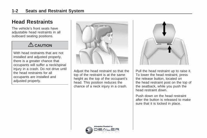
Head RestraintsThe vehicle’s front seats haveadjustable head restraints in alloutboard seating positions.
{ CAUTION
With head restraints that are notinstalled and adjusted properly,there is a greater chance thatoccupants will suffer a neck/spinalinjury in a crash. Do not drive untilthe head restraints for alloccupants are installed andadjusted properly.
Adjust the head restraint so that thetop of the restraint is at the sameheight as the top of the occupant’shead. This position reduces thechance of a neck injury in a crash.
Pull the head restraint up to raise it.To lower the head restraint, pressthe release button, located onthe head restraint post on the top ofthe seatback, while you push thehead restraint down.
Push down on the head restraintafter the button is released to makesure that it is locked in place.
1-2 Seats and Restraint System
Information Provided by:
Front Seats
Manual Seats
{ CAUTION
You can lose control of thevehicle if you try to adjust amanual driver’s seat while thevehicle is moving. The suddenmovement could startle andconfuse you, or make you push apedal when you do not want to.Adjust the driver’s seat only whenthe vehicle is not moving.
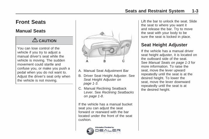
A. Manual Seat Adjustment BarB. Driver Seat Height Adjuster. See
Seat Height Adjuster onpage 1-3.
C. Manual Reclining SeatbackLever. See Reclining Seatbackson page 1-8.
If the vehicle has a manual bucketseat you can adjust the seatforward or rearward with the barlocated under the front of the seatcushion.
Lift the bar to unlock the seat. Slidethe seat to where you want itand release the bar. Try to movethe seat with your body to besure the seat is locked in place.
Seat Height AdjusterIf the vehicle has a manual driverseat height adjuster, it is located onthe outboard side of the seat.See Manual Seats on page 1-3 formore information. To raise theseat, move the lever upwardrepeatedly until the seat is at thedesired height. To lower theseat, move the lever downwardrepeatedly until the seat is atthe desired height.
Seats and Restraint System 1-3
Information Provided by:

Power Seats
A. Power Seat Adjustment ControlB. Reclining Seatbacks on
page 1-8.C. Power Lumbar on page 1-5.
If the vehicle has power seats, thecontrols are located on theoutboard side of the seats.
Move the seat forward or rearwardby sliding the power seatadjustment control (A) forward orrearward.
The vehicle may have additionalfeatures to adjust the power seat:
• Raise or lower the entire seatby moving the power seatadjustment control (A) upor down.
• Raise or lower the front part ofthe seat cushion by movingthe front of the control upor down.
• Raise or lower the rear part ofthe seat cushion by movingthe rear of the control upor down.
The vehicle may have a memoryfunction which allows seat settingsto be saved and recalled. SeeMemory Seat and Mirrors onpage 1-6 for more information.
Manual Lumbar
If the vehicle has this feature, thehandle is located on the inboard sideof the seatback. See ManualSeats on page 1-3 for moreinformation.
Turn the handle rearward todecrease lumbar support. Turn thehandle forward to increaselumbar support.
The lumbar support may need to beadjusted when changing theseating position.
Driver Seat with Power SeatControl, Power Recline, and
Power Lumbar shown
1-4 Seats and Restraint System
Information Provided by:

Power LumbarIf the seats have power lumbar, thecontrols used to operate thisfeature are located on the outboardside of the seats. See “PowerLumbar” under Power Seats onpage 1-4 for more information.
To increase or decrease lumbarsupport, press and hold the frontor rear of the control (C).
Release the control when theseatback reaches the desired levelof lumbar support.
The lumbar support may need tobe adjusted when changingthe seating position.
Heated SeatsOn vehicles with heated front seats,the controls are located on the centerconsole. To operate the heated seatsthe engine must be running.
I (Heated Seatback): Press toturn on the heated seatback.
J (Heated Seat and Seatback):Press to turn on or off the heatedseat and seatback.The light on the button will comeon to indicate that the feature is on.Each time the button is pressed, thetemperature settings change fromhigh, to medium, to low, to off.Indicator lights above the buttonwill show the level of heatselected: three for high, twofor medium, and one for low.The passenger seat may take longerto heat up.If the vehicle has remote vehiclestart and is started using the remotekeyless entry transmitter, the frontheated seats will be turned on to thehigh setting if it is cold outside.
See “Remote Vehicle Start” underRemote Keyless Entry (RKE)System Operation on page 2-4.When the ignition is turned on, theheated seat feature will turn off.To turn the heated seat feature backon, press the desired button.
Heated and Cooled SeatsIf the front seats have the heatedand cooled seat feature, the buttonsused to control this feature arelocated on the front doors nearthe door handle.
H (Cooled Seat): To cool theentire seat, press the button withthe cooled seat symbol.
This symbol will appear on theclimate control display to indicatethat the feature is on. Press thebutton to cycle through thetemperature settings of high,medium, and low and to turn thecooled seat off. Indicator bars nextto the symbol designate the level ofcooling selected: three for high, twofor medium, and one for low.
Seats and Restraint System 1-5
Information Provided by:

z (Heated Seat and Seatback): Toheat the entire seat, press thebutton with the heated seat andseatback symbol.
This symbol will appear on theclimate control display to indicatethat the feature is on. Press thebutton to cycle through thetemperature settings of high,medium, and low and to turn theheated seat off. Indicator bars next tothe symbol designate the level ofheat selected: three for high, two formedium, and one for low.
The heated and cooled seats willbe canceled after the ignition isturned off. To use the heated andcooled seat feature after the vehicleis started, you will need to press theappropriate seat button again.
Memory Seat and Mirrors
On vehicles with the memorypackage, the controls for this featureare located on the driver doorpanel. The controls are used toprogram and recall memory settingsfor the driver seat and outsidemirrors.
To save positions in memory:
1. Adjust the driver seat, includingthe seatback recliner and bothoutside mirrors to a comfortableposition.See Outside Power Mirrors onpage 2-32 for more information.
Not all mirrors will have theability to save and recallthe mirror positions.
2. Press and hold button 1 untiltwo beeps let you know thatthe position has been stored.
A second seating and mirror positioncan be programmed by repeatingthe above steps and pressingbutton 2.
To recall the memory positions, thevehicle must be in P (Park). Pressand release either button 1 orbutton 2 corresponding to thedesired driving position. The seatand outside mirrors will move to theposition previously stored. You willhear a single beep.
Using the RKE transmitter toenter the vehicle, with the remoterecall memory feature on, causesautomatic seat and mirroradjustment. There is no adjustmentwhen the position has not beenchanged by another seatingposition or the easy exit feature.
1-6 Seats and Restraint System
Information Provided by:

See “MEMORY SEAT RECALL”under DIC Vehicle Customization(With DIC Buttons) on page 3-65 formore information.
To stop recall movement of thememory feature at any time, pressone of the power seat controls,memory buttons, or power mirrorbuttons.
If something has blocked the driverseat while recalling a memoryposition, the driver seat recallmay stop working. If this happens,press the appropriate control forthe area that is not recallingfor two seconds, after theobstruction is removed. Then tryrecalling the memory position againby pressing the appropriatememory button. If the memoryposition is still not being recalled,see your dealer/retailer for service.
Easy Exit SeatThe control for this feature islocated on the driver door panelbetween buttons 1 and 2.
With the vehicle in P (Park), theexit position can be recalledby pressing the exit button. You willhear a single beep. The driverseat will move back.
If the easy exit seat feature is on inthe Driver Information Center (DIC),automatic seat movement will occurwhen the key is removed from theignition. See “EASY EXIT SEAT”under DIC Vehicle Customization(With DIC Buttons) on page 3-65 formore information.
Further programming for thememory seat feature can be doneusing the DIC. You can selector cancel the following:
• The automatic easy exit seatfeature.
• The remote memory seat recallfeature.
For programming information, seeDIC Vehicle Customization (WithDIC Buttons) on page 3-65.
Seats and Restraint System 1-7
Information Provided by:
Reclining SeatbacksManual Reclining Seatbacks
{ CAUTION
You can lose control of thevehicle if you try to adjust amanual driver’s seat while thevehicle is moving. The suddenmovement could startle andconfuse you, or make you push apedal when you do not want to.Adjust the driver’s seat only whenthe vehicle is not moving.
{ CAUTION
If either seatback is not locked, itcould move forward in a suddenstop or crash. That could causeinjury to the person sitting there.Always push and pull on theseatbacks to be sure they arelocked.
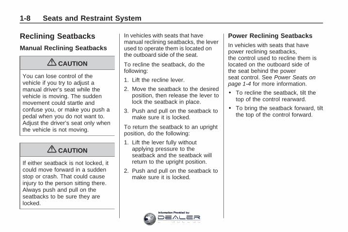
In vehicles with seats that havemanual reclining seatbacks, the leverused to operate them is located onthe outboard side of the seat.
To recline the seatback, do thefollowing:
1. Lift the recline lever.
2. Move the seatback to the desiredposition, then release the lever tolock the seatback in place.
3. Push and pull on the seatback tomake sure it is locked.
To return the seatback to an uprightposition, do the following:
1. Lift the lever fully withoutapplying pressure to theseatback and the seatback willreturn to the upright position.
2. Push and pull on the seatback tomake sure it is locked.
Power Reclining SeatbacksIn vehicles with seats that havepower reclining seatbacks,the control used to recline them islocated on the outboard side ofthe seat behind the powerseat control. See Power Seats onpage 1-4 for more information.
• To recline the seatback, tilt thetop of the control rearward.
• To bring the seatback forward, tiltthe top of the control forward.
1-8 Seats and Restraint System
Information Provided by:

{ CAUTION
Sitting in a reclined position whenthe vehicle is in motion can bedangerous. Even when buckledup, the safety belts cannot dotheir job when reclined like this.
The shoulder belt cannot do itsjob because it will not be againstyour body. Instead, it will be infront of you. In a crash, you couldgo into it, receiving neck or otherinjuries.
The lap belt cannot do its jobeither. In a crash, the belt couldgo up over your abdomen. Thebelt forces would be there, not atyour pelvic bones. This couldcause serious internal injuries.
For proper protection when thevehicle is in motion, have theseatback upright. Then sit wellback in the seat and wear thesafety belt properly.
Do not have a seatback reclined ifyour vehicle is moving.
Rear Seats
Rear Seat Operation
A. Seat Adjustment HandleB. Reclining Seatback StrapC. Sliding Seat Lever
Seats and Restraint System 1-9
Information Provided by:

Entering and Exiting theThird Row
{ CAUTION
Using the third row seatingposition while the second row isfolded, or folded and tumbled,could cause injury in a sudden stopor crash. Be sure to return the seatto the passenger seating position.Push and pull on the seat to makesure it is locked into place.
Notice: Folding a rear seat withthe safety belts still fastened maycause damage to the seat or thesafety belts. Always unbuckle thesafety belts and return them totheir normal stowed positionbefore folding a rear seat.
To access the third row:
1. Remove objects on the floor infront of or on the second rowseat, or in the seat tracks onthe floor.
2. Move the front center consolearmrest completely forward.See Center Console Storage onpage 2-52.
3. Place folding armrests in theupright position.
4. Ensure that the safety belt isunfastened and in the stowedposition.
5. Pull the sliding seat lever (C)forward and move the seatbackforward. The seat cushionwill fold, and the entire seat willslide forward.
1-10 Seats and Restraint System
Information Provided by:

Returning the Seat to theSeating PositionTo return the second row seat to itsnormal seating position:
1. Remove objects on the floorbehind the second row seator in the seat tracks on the floor.
2. Pull the seatback rearward until itis locked in place.
3. Slide the seat rearward bypushing on the seatback until it islocked into place.
4. Push down on the rear of theseat cushion until it is lockedin place.
5. Push and pull on the seatbackand seat cushion to make surethey are locked in place.
6. Check that the safety belt is notunder the seat cushion.
Reclining the SeatbacksTo recline the seatback:
1. Leaning forward in the seat, pullthe reclining seatback strap (B).
2. Move the seatback to the desiredposition, then release the strapto lock the seatback in place.
3. Push and pull on the seatback tomake sure it is locked.
Folding the Rear SeatTo fold the second row seats:
1. Remove anything on or underthe seat.
2. Place the armrest in the uprightposition, and unfasten thesafety belt.
3. Pull forward on the recliningseatback strap (B) and pushdown on the seatback.If the headrest touches the frontseat, slide the second rowseat rearward.
To return the seatback to theseating position, lift the upper cornerof the seatback and push itrearward until it locks into place.Push and pull on the seatbackto make sure it is locked.
Adjusting the SeatsTo adjust the second row seats, pulloutward on the seat adjustmenthandle (A). Slide the seat forward orrearward to the desired position.Release the handle and push andpull on the seat to make sure it islocked.
Seats and Restraint System 1-11
Information Provided by:

Third Row Seats
{ CAUTION
Using the third row seatingposition while the second row isfolded, or pushed forward in theentry position, could cause injuryin a sudden stop or crash. Besure to return the seat to thepassenger seating position. Pushand pull on the seat to make sureit is locked into place.
The third row seats can be foldedforward or removed.
Notice: Folding a rear seat withthe safety belts still fastened maycause damage to the seat or thesafety belts. Always unbuckle thesafety belts and return them totheir normal stowed positionbefore folding a rear seat.
To fold the seatback:
1. Remove anything on or underthe seat.
2. Disconnect the rear safety beltmini-latch, using a key in theslot on the mini-buckle, letthe belt retract into the headliner.Stow the mini-latch in theholder located in the headliner.
3. Pull up on the release leverlocated on the back of theseat. The headrest movesforward automatically.
4. Push the seatback forward tolay flat.
To return the seatback to theseating position:
1. Raise the seatback into place byusing the pullstrap from the rearof the vehicle, or by pushingit into place from inside thevehicle.
1-12 Seats and Restraint System
Information Provided by:

2. The headrest must be lockedinto place before sitting inthe seat.
{ CAUTION
If either seatback is not locked, itcould move forward in a suddenstop or crash. That could causeinjury to the person sitting there.Always push and pull on theseatbacks to be sure they arelocked.
3. Push and pull on the seatback tomake sure it is locked in place.
{ CAUTION
A safety belt that is improperlyrouted, not properly attached,or twisted will not provide theprotection needed in a crash. Theperson wearing the belt could beseriously injured. After raising the
(Continued)
CAUTION (Continued)
rear seatback, always check to besure that the safety belts areproperly routed and attached, andare not twisted.
4. Reconnect the center safety beltmini-latch to the mini-buckle.Do not let it twist.
5. Pull on the safety belt to be surethe mini-latch is secure.
Removing the ThirdRow Seats1. Remove the cargo management
system, if it is in the vehicle.See Cargo Management Systemon page 2-55.
2. Remove anything on or underthe seat.
Notice: Folding a rear seat withthe safety belts still fastened maycause damage to the seat or thesafety belts. Always unbuckle the
safety belts and return them totheir normal stowed positionbefore folding a rear seat.
3. Fold the seatback down. See“Folding the Seatback” earlierin this section.
4. Remove the rear bolts located onthe floor on each side of the seat.
5. Remove the seat by tilting itslightly upward, and thenpulling it out of the rear ofthe vehicle in one motion.
6. Replace the bolts in the floorholes for storage.
Installing the Third Row Seats1. Before installing the seat the
seatback must be folded forward.See “Folding the Seatback”earlier in this section.The seats must be placed in theproper locations to attachcorrectly. The wider seat must beinstalled on the driver side andthe narrower seat on thepassenger side.
Seats and Restraint System 1-13
Information Provided by:

Remove the bolts from the holesin the floor before installing theseats.
2. Place the seat on the vehiclefloor so that the front seathooks are on the vehicle bars.
3. Reinstall the bolts, and torque to55 Y (41 lb ft). Pull up on theseat to make sure it is lockedin place.
4. Raise the seatback to its uprightposition. Push and pull on theseatback to make sure it islocked into place.
5. Push the headrest up intoposition. Push and pull onthe headrest to make sure it islocked into place.
6. Reconnect the center safety beltmini-latch to the mini-buckle. Donot let it twist.
Safety Belts
Safety Belts: They Arefor EveryoneThis section of the manual describeshow to use safety belts properly.It also describes some things not todo with safety belts.
{ CAUTION
Do not let anyone ride where asafety belt cannot be wornproperly. In a crash, if you or yourpassenger(s) are not wearingsafety belts, the injuries can bemuch worse. You can hit thingsinside the vehicle harder or beejected from the vehicle. You andyour passenger(s) can beseriously injured or killed. In thesame crash, you might not be, ifyou are buckled up. Always fastenyour safety belt, and check thatyour passenger(s) are restrainedproperly too.
{ CAUTION
It is extremely dangerous to ridein a cargo area, inside or outsideof a vehicle. In a collision, peopleriding in these areas are morelikely to be seriously injured orkilled. Do not allow people to ridein any area of your vehicle that isnot equipped with seats andsafety belts. Be sure everyone inyour vehicle is in a seat and usinga safety belt properly.
This vehicle has indicators as areminder to buckle the safety belts.See Safety Belt Reminders onpage 3-32 for additional information.
In most states and in all Canadianprovinces, the law requires wearingsafety belts. Here is why:
You never know if you will be in acrash. If you do have a crash,you do not know if it will be aserious one.
1-14 Seats and Restraint System
Information Provided by:

A few crashes are mild, and somecrashes can be so serious that evenbuckled up, a person would notsurvive. But most crashes arein between. In many of them, peoplewho buckle up can survive andsometimes walk away. Withoutsafety belts they could have beenbadly hurt or killed.
After more than 40 years of safetybelts in vehicles, the facts are clear.In most crashes buckling up doesmatter... a lot!
Why Safety Belts WorkWhen you ride in or on anything,you go as fast as it goes.
Take the simplest vehicle. Supposeit is just a seat on wheels.
Put someone on it.
Seats and Restraint System 1-15
Information Provided by:

Get it up to speed. Then stop thevehicle. The rider does not stop.
The person keeps going untilstopped by something. In a realvehicle, it could be the windshield...
or the instrument panel...
or the safety belts!
1-16 Seats and Restraint System
Information Provided by:

With safety belts, you slow down asthe vehicle does. You get moretime to stop. You stop over moredistance, and your strongest bonestake the forces. That is whysafety belts make such good sense.
Questions and AnswersAbout Safety Belts
Q: Will I be trapped in the vehicleafter a crash if I am wearing asafety belt?
A: You could be — whether you arewearing a safety belt or not. Butyour chance of being consciousduring and after an accident,so you can unbuckle and get out,is much greater if you arebelted. And you can unbuckle asafety belt, even if you areupside down.
Q: If my vehicle has airbags, whyshould I have to wear safetybelts?
A: Airbags are supplementalsystems only; so they work withsafety belts — not instead ofthem. Whether or not an airbagis provided, all occupantsstill have to buckle up to get themost protection. That is truenot only in frontal collisions, butespecially in side and othercollisions.
Q: If I am a good driver, and Inever drive far from home,why should I wear safetybelts?
A: You may be an excellent driver,but if you are in a crash — evenone that is not your fault — youand your passenger(s) can behurt. Being a good driver does notprotect you from things beyondyour control, such as bad drivers.
Most accidents occur within25 miles (40 km) of home. Andthe greatest number of seriousinjuries and deaths occur atspeeds of less than 40 mph(65 km/h).
Safety belts are for everyone.
How to Wear Safety BeltsProperlyThis section is only for people ofadult size.
Be aware that there are specialthings to know about safetybelts and children. And there aredifferent rules for smaller childrenand infants. If a child will be riding inthe vehicle, see Older Children onpage 1-27 or Infants and YoungChildren on page 1-29. Follow thoserules for everyone’s protection.
It is very important for all occupantsto buckle up. Statistics show thatunbelted people are hurt more oftenin crashes than those who arewearing safety belts.
Seats and Restraint System 1-17
Information Provided by:

Occupants who are not buckled upcan be thrown out of the vehiclein a crash. And they can strikeothers in the vehicle who arewearing safety belts.
First, before you or yourpassenger(s) wear a safety belt,there is important informationyou should know.
Sit up straight and always keep yourfeet on the floor in front of you.The lap part of the belt should be
worn low and snug on the hips, justtouching the thighs. In a crash, thisapplies force to the strong pelvicbones and you would be less likely toslide under the lap belt. If you slidunder it, the belt would apply forceon your abdomen. This could causeserious or even fatal injuries.The shoulder belt should go overthe shoulder and across the chest.These parts of the body are best ableto take belt restraining forces.
The shoulder belt locks if there is asudden stop or crash.
Q: What is wrong with this?
A: The shoulder belt is too loose. Itwill not give as much protectionthis way.
{ CAUTION
You can be seriously hurt if yourshoulder belt is too loose. In acrash, you would move forwardtoo much, which could increaseinjury. The shoulder belt should fitsnugly against your body.
1-18 Seats and Restraint System
Information Provided by:

Q: What is wrong with this?
A: The lap belt is too loose. It willnot give nearly as muchprotection this way.
{ CAUTION
You can be seriously hurt if yourlap belt is too loose. In a crash,you could slide under the lap beltand apply force on your abdomen.This could cause serious or evenfatal injuries. The lap belt shouldbe worn low and snug on thehips, just touching the thighs.
Q: What is wrong with this?
A: The belt is buckled in the wrongbuckle.
{ CAUTION
You can be seriously injured ifyour belt is buckled in the wrongplace like this. In a crash, the beltwould go up over your abdomen.The belt forces would be there,not on the pelvic bones. Thiscould cause serious internalinjuries. Always buckle your beltinto the buckle nearest you.
Seats and Restraint System 1-19
Information Provided by:

Q: What is wrong with this?
A: The belt is over an armrest.
{ CAUTION
You can be seriously injured ifyour belt goes over an armrestlike this. The belt would be muchtoo high. In a crash, you can slideunder the belt. The belt force
(Continued)
CAUTION (Continued)
would then be applied on theabdomen, not on the pelvicbones, and that could causeserious or fatal injuries. Be surethe belt goes under the armrests.
Q: What is wrong with this?
A: The shoulder belt is worn underthe arm. It should be worn overthe shoulder at all times.
{ CAUTION
You can be seriously injured ifyou wear the shoulder belt underyour arm. In a crash, your bodywould move too far forward, whichwould increase the chance ofhead and neck injury. Also, thebelt would apply too much forceto the ribs, which are not asstrong as shoulder bones. Youcould also severely injure internalorgans like your liver or spleen.The shoulder belt should go overthe shoulder and across thechest.
1-20 Seats and Restraint System
Information Provided by:

Q: What is wrong with this?
A: The belt is behind the body.
{ CAUTION
You can be seriously injured bynot wearing the lap-shoulder beltproperly. In a crash, you wouldnot be restrained by the shoulderbelt. Your body could move toofar forward increasing the chanceof head and neck injury. Youmight also slide under the lapbelt. The belt force would then beapplied right on the abdomen.That could cause serious or fatalinjuries. The shoulder belt shouldgo over the shoulder and acrossthe chest.
Q: What is wrong with this?
A: The belt is twisted acrossthe body.
{ CAUTION
You can be seriously injured by atwisted belt. In a crash, you wouldnot have the full width of the beltto spread impact forces. If a beltis twisted, make it straight so itcan work properly, or ask yourdealer/retailer to fix it.
Seats and Restraint System 1-21
Information Provided by:

Lap-Shoulder BeltAll seating positions in the vehiclehave a lap-shoulder belt.
If you are using a rear seatingposition with a detachable safetybelt and the safety belt is notattached, see Third Row Seats onpage 1-12 for instruction onreconnecting the safety belt to themini-buckle.
The following instructions explainhow to wear a lap-shoulder beltproperly.
1. Adjust the seat, if the seat isadjustable, so you can sit upstraight. To see how, see “Seats”in the Index.
2. Pick up the latch plate and pullthe belt across you. Do not letit get twisted.The lap-shoulder belt may lock ifyou pull the belt across youvery quickly. If this happens, letthe belt go back slightly tounlock it. Then pull the beltacross you more slowly.If the shoulder portion of apassenger belt is pulled out allthe way, the child restraintlocking feature may be engaged.If this happens, let the belt goback all the way and start again.
3. Push the latch plate into thebuckle until it clicks.
4. Pull up on the latch plate tomake sure it is secure. If the beltis not long enough, see SafetyBelt Extender on page 1-27.Position the release button onthe buckle so that the safety beltcould be quickly unbuckled ifnecessary.
5. If equipped with a shoulder beltheight adjuster, move it to theheight that is right for you.
1-22 Seats and Restraint System
Information Provided by:

See “Shoulder Belt HeightAdjustment” later in this sectionfor instructions on use andimportant safety information.
6. To make the lap part tight, pullup on the shoulder belt.It may be necessary to pull thestitching on the safety beltthrough the latch plate to fullytighten the lap belt on smalleroccupants.
To unlatch the belt, push the buttonon the buckle. The belt shouldreturn to its stowed position. Slidethe latch plate up the safetybelt webbing when the safety belt isnot in use. The latch plate shouldrest on the stitching on thesafety belt, near the guide loop onthe side wall.
Before a door is closed, be sure thesafety belt is out of the way. If adoor is slammed against a safetybelt, damage can occur to both thesafety belt and the vehicle.
Shoulder Belt Height AdjusterThe vehicle has a shoulder beltheight adjuster for the driver andright front passenger seatingpositions.
Adjust the height so that the shoulderportion of the belt is centered on theshoulder. The belt should be awayfrom the face and neck, but notfalling off of the shoulder. Impropershoulder belt height adjustmentcould reduce the effectiveness of thesafety belt in a crash.
To move it down, push down on thebutton (A) and move the heightadjuster to the desired position.
Seats and Restraint System 1-23
Information Provided by:

You can move the height adjusterup by pushing up on the shoulderbelt guide.
After the adjuster is set to thedesired position, try to move it downwithout pushing the button tomake sure it has locked intoposition.
Safety Belt PretensionersThis vehicle has safety beltpretensioners for the front outboardoccupants. Although the safetybelt pretensioners cannot be seen,they are part of the safety beltassembly. They can help tighten thesafety belts during the earlystages of a moderate to severefrontal, near frontal, or rear crash ifthe threshold conditions forpretensioner activation are met.And, for vehicles with side impactairbags, safety belt pretensionerscan help tighten the safety belts in aside crash or a rollover event.
Pretensioners work only once. If thepretensioners activate in a crash,they will need to be replaced,and probably other new parts forthe vehicle’s safety belt system.See Replacing Restraint SystemParts After a Crash on page 1-60.
Rear Safety Belt ComfortGuidesRear shoulder belt comfort guidesmay provide added safety beltcomfort for older children who haveoutgrown booster seats and forsome adults. When installed on ashoulder belt, the comfort guidepositions the shoulder belt awayfrom the neck and head.
There is a guide for each outboardpassenger position in the second rowseat and all passenger positions inthe third row.
Here is how to install a comfort guideto the safety belt:
1. For the outboard positions,remove the guide from its storageclip on the interior body.For the third row centerposition, locate the comfortguide which is located in astorage pocket, at the top ofthe seat, under the headrest onthe driver’s side of the vehicle.
Outboard Positions
1-24 Seats and Restraint System
Information Provided by:

To access the comfort guide,you will first need to move theheadrest forward by pulling onthe handle behind the seatback.The comfort guide will now beaccessible.
Pull the comfort guide out of itsstorage location and thenreturn the headrest to its uprightposition.
The elastic cord on the comfortguide is adjustable. You canmake it longer or shorterby squeezing both ends of theplastic adjuster.
2. Place the guide over the belt andinsert the two edges of the beltinto the slots of the guide.
3. Be sure that the belt is nottwisted and it lies flat. The elasticcord must be under the beltand the guide on top.
Third Row Center Position
Seats and Restraint System 1-25
Information Provided by:

{ CAUTION
A safety belt that is not properlyworn may not provide theprotection needed in a crash. Theperson wearing the belt could beseriously injured. The shoulderbelt should go over the shoulderand across the chest. These partsof the body are best able to takebelt restraining forces.
4. Buckle, position, and release thesafety belt as describedpreviously in this section. Makesure that the shoulder beltcrosses the shoulder.
To remove and store the comfortguide, squeeze the belt edgestogether so that the safety belt canbe removed from the guide.Slide the guide into its storagelocation or on its storage clip.
Safety Belt Use DuringPregnancySafety belts work for everyone,including pregnant women. Like alloccupants, they are more likelyto be seriously injured if they do notwear safety belts.
A pregnant woman should wear alap-shoulder belt, and the lap portionshould be worn as low as possible,below the rounding, throughoutthe pregnancy.
1-26 Seats and Restraint System
Information Provided by:

The best way to protect the fetus isto protect the mother. When asafety belt is worn properly,it is more likely that the fetus will notbe hurt in a crash. For pregnantwomen, as for anyone, the key tomaking safety belts effective iswearing them properly.
Safety Belt ExtenderIf the vehicle’s safety belt will fastenaround you, you should use it.
But if a safety belt is not longenough, your dealer/retailer willorder you an extender. When yougo in to order it, take the heaviestcoat you will wear, so the extenderwill be long enough for you. Tohelp avoid personal injury, do not letsomeone else use it, and use itonly for the seat it is made to fit. Theextender has been designed foradults. Never use it for securingchild seats. To wear it, attach it tothe regular safety belt. For moreinformation, see the instructionsheet that comes with the extender.
Child Restraints
Older Children
Older children who have outgrownbooster seats should wear thevehicle’s safety belts.
The manufacturer’s instructions thatcome with the booster seat, statethe weight and height limitations forthat booster.
Use a booster seat with alap-shoulder belt until the childpasses the below fit test:
• Sit all the way back on the seat.Do the knees bend at the seatedge? If yes, continue. If no,return to the booster seat.
• Buckle the lap-shoulder belt.Does the shoulder belt rest on theshoulder? If yes, continue. If no,try using the rear safety beltcomfort guide. See “Rear SafetyBelt Comfort Guides” underLap-Shoulder Belt on page 1-22for more information. If theshoulder belt still does not rest onthe shoulder, then return to thebooster seat.
• Does the lap belt fit low and snugon the hips, touching the thighs? Ifyes, continue. If no, return to thebooster seat.
• Can proper safety belt fit bemaintained for the length of thetrip? If yes, continue. If no, returnto the booster seat.
Seats and Restraint System 1-27
Information Provided by:
Q: What is the proper way towear safety belts?
A: An older child should wear alap-shoulder belt and get theadditional restraint a shoulderbelt can provide. The shoulderbelt should not cross the face orneck. The lap belt should fitsnugly below the hips, justtouching the top of the thighs.This applies belt force tothe child’s pelvic bones in acrash. It should never be wornover the abdomen, whichcould cause severe or even fatalinternal injuries in a crash.
Also see “Rear Safety Belt ComfortGuides” under Lap-Shoulder Belton page 1-22.
According to accident statistics,children and infants are safer whenproperly restrained in a childrestraint system or infant restraintsystem secured in a rear seatingposition.
In a crash, children who are notbuckled up can strike other peoplewho are buckled up, or can bethrown out of the vehicle. Olderchildren need to use safetybelts properly.
{ CAUTION
Never do this.
Never allow two children to wearthe same safety belt. The safetybelt can not properly spread theimpact forces. In a crash, the twochildren can be crushed togetherand seriously injured. A safetybelt must be used by only oneperson at a time.
1-28 Seats and Restraint System
Information Provided by:

{ CAUTION
Never do this.
Never allow a child to wear thesafety belt with the shoulder beltbehind their back. A child can beseriously injured by not wearingthe lap-shoulder belt properly. In acrash, the child would not berestrained by the shoulder belt.The child could move too farforward increasing the chance ofhead and neck injury. The childmight also slide under the lapbelt. The belt force would then beapplied right on the abdomen.That could cause serious or fatalinjuries. The shoulder belt shouldgo over the shoulder and acrossthe chest.
Infants and YoungChildrenEveryone in a vehicle needsprotection! This includes infants andall other children. Neither thedistance traveled nor the age andsize of the traveler changes theneed, for everyone, to use safetyrestraints. In fact, the law inevery state in the United States andin every Canadian province sayschildren up to some age mustbe restrained while in a vehicle.
{ CAUTION
Children can be seriously injuredor strangled if a shoulder belt iswrapped around their neck andthe safety belt continues totighten. Never leave childrenunattended in a vehicle and neverallow children to play with thesafety belts.
Airbags plus lap-shoulder belts offerprotection for adults and olderchildren, but not for young childrenand infants. Neither the vehicle’ssafety belt system nor its airbagsystem is designed for them. Everytime infants and young childrenride in vehicles, they should havethe protection provided byappropriate child restraints.
Children who are not restrainedproperly can strike other people, orcan be thrown out of the vehicle.
Seats and Restraint System 1-29
Information Provided by:

{ CAUTION
Never do this.
Never hold an infant or a childwhile riding in a vehicle. Due tocrash forces, an infant or a childwill become so heavy it is notpossible to hold it during a crash.For example, in a crash at only25 mph (40 km/h), a 12 lb (5.5 kg)infant will suddenly become a240 lb (110 kg) force on aperson’s arms. An infant shouldbe secured in an appropriaterestraint.
{ CAUTION
Never do this.
Children who are up against, orvery close to, any airbag when itinflates can be seriously injured orkilled. Never put a rear-facingchild restraint in the right frontseat. Secure a rear-facing child
(Continued)
CAUTION (Continued)
restraint in a rear seat. It is alsobetter to secure a forward-facingchild restraint in a rear seat. If youmust secure a forward-facing childrestraint in the right front seat,always move the front passengerseat as far back as it will go.
1-30 Seats and Restraint System
Information Provided by:

Q: What are the different types ofadd-on child restraints?
A: Add-on child restraints, which arepurchased by the vehicle’sowner, are available in four basictypes. Selection of a particularrestraint should take intoconsideration not only the child’sweight, height, and age but alsowhether or not the restraint will becompatible with the motor vehiclein which it will be used.
For most basic types of childrestraints, there are manydifferent models available. Whenpurchasing a child restraint,be sure it is designed to be usedin a motor vehicle. If it is, therestraint will have a label sayingthat it meets federal motorvehicle safety standards.
The restraint manufacturer’sinstructions that come with therestraint state the weightand height limitations for aparticular child restraint.
In addition, there are many kindsof restraints available forchildren with special needs.
{ CAUTION
To reduce the risk of neck andhead injury during a crash, infantsneed complete support. This isbecause an infant’s neck is notfully developed and its headweighs so much compared withthe rest of its body. In a crash, aninfant in a rear-facing childrestraint settles into the restraint,so the crash forces can bedistributed across the strongestpart of an infant’s body, the backand shoulders. Infants shouldalways be secured in rear-facingchild restraints.
{ CAUTION
A young child’s hip bones are stillso small that the vehicle’s regularsafety belt may not remain low onthe hip bones, as it should.Instead, it may settle up aroundthe child’s abdomen. In a crash,the belt would apply force on abody area that is unprotected byany bony structure. This alonecould cause serious or fatalinjuries. To reduce the risk ofserious or fatal injuries during acrash, young children shouldalways be secured in appropriatechild restraints.
Seats and Restraint System 1-31
Information Provided by:

Child Restraint Systems
A rear-facing infant seat (A) providesrestraint with the seating surfaceagainst the back of the infant.
The harness system holds the infantin place and, in a crash, acts tokeep the infant positioned inthe restraint.
A forward-facing child seat (B)provides restraint for the child’s bodywith the harness.
A booster seat (C) is a childrestraint designed to improve the fitof the vehicle’s safety belt system.A booster seat can also help a childto see out the window.
(A) Rear-Facing Infant Seat
(B) Forward-Facing Child Seat (C) Booster Seats
1-32 Seats and Restraint System
Information Provided by:

Securing an Add-On ChildRestraint in the Vehicle
{ CAUTION
A child can be seriously injured orkilled in a crash if the childrestraint is not properly secured inthe vehicle. Secure the childrestraint properly in the vehicleusing the vehicle’s safety belt orLATCH system, following theinstructions that came with thatchild restraint and the instructionsin this manual.
To help reduce the chance of injury,the child restraint must be securedin the vehicle. Child restraintsystems must be secured in vehicleseats by lap belts or the lap beltportion of a lap-shoulder belt, or bythe LATCH system. See Lower
Anchors and Tethers for Children(LATCH) on page 1-35 for moreinformation. A child can beendangered in a crash if the childrestraint is not properly securedin the vehicle.
When securing an add-on childrestraint, refer to the instructions thatcome with the restraint which maybe on the restraint itself or in abooklet, or both, and to this manual.The child restraint instructions areimportant, so if they are notavailable, obtain a replacementcopy from the manufacturer.
Keep in mind that an unsecuredchild restraint can move aroundin a collision or sudden stopand injure people in the vehicle. Besure to properly secure any childrestraint in the vehicle — even whenno child is in it.
Securing the Child Within theChild Restraint
{ CAUTION
A child can be seriously injured orkilled in a crash if the child is notproperly secured in the childrestraint. Secure the child properlyfollowing the instructions thatcame with that child restraint.
Where to Put theRestraintAccording to accident statistics,children and infants are safer whenproperly restrained in a child restraintsystem or infant restraint systemsecured in a rear seating position.We recommend that children andchild restraints be secured in a rearseat, including: an infant or a childriding in a rear-facing child restraint;a child riding in a forward-facing childseat; an older child riding in a boosterseat; and children, who are largeenough, using safety belts.
Seats and Restraint System 1-33
Information Provided by:

A label on the sun visor says,“Never put a rear-facing childrestraint in the front.” This isbecause the risk to the rear-facingchild is so great, if the airbagdeploys.
{ CAUTION
A child in a rear-facing childrestraint can be seriously injuredor killed if the right frontpassenger airbag inflates. This isbecause the back of therear-facing child restraint wouldbe very close to the inflatingairbag. A child in a forward-facingchild restraint can be seriouslyinjured or killed if the right frontpassenger airbag inflates and thepassenger seat is in a forwardposition.
(Continued)
CAUTION (Continued)
Even if the passenger sensingsystem has turned off the rightfront passenger frontal airbag, nosystem is fail-safe. No one canguarantee that an airbag will notdeploy under some unusualcircumstance, even though it isturned off.
Secure rear-facing child restraintsin a rear seat, even if the airbag isoff. If you secure a forward-facingchild restraint in the right front seat,always move the front passengerseat as far back as it will go. It isbetter to secure the child restraintin a rear seat.
See Passenger Sensing Systemon page 1-53 for additionalinformation.
When securing a child restraint in arear seating position, study theinstructions that came with the childrestraint to make sure it iscompatible with this vehicle.
Wherever a child restraint isinstalled, be sure to secure the childrestraint properly.
Keep in mind that an unsecuredchild restraint can move aroundin a collision or sudden stopand injure people in the vehicle.Be sure to properly secure any childrestraint in the vehicle — evenwhen no child is in it.
1-34 Seats and Restraint System
Information Provided by:

Lower Anchors andTethers for Children(LATCH)The LATCH system holds a childrestraint during driving or in a crash.This system is designed to makeinstallation of a child restraint easier.The LATCH system uses anchorsin the vehicle and attachmentson the child restraint that are madefor use with the LATCH system.
Make sure that a LATCH-compatiblechild restraint is properly installedusing the anchors, or use thevehicle’s safety belts to secure therestraint, following the instructionsthat came with that restraint,and also the instructions in thismanual. When installing achild restraint with a top tether,you must also use either the loweranchors or the safety belts toproperly secure the child restraint.A child restraint must never beattached using only the top tetherand anchor.
In order to use the LATCH systemin your vehicle, you need a childrestraint that has LATCHattachments. The child restraintmanufacturer will provide you withinstructions on how to use thechild restraint and its attachments.The following explains how to attacha child restraint with theseattachments in your vehicle.
Not all vehicle seating positions orchild restraints have lower anchorsand attachments or top tetheranchors and attachments.
Lower Anchors
Lower anchors (A) are metal barsbuilt into the vehicle. There aretwo lower anchors for each LATCH
seating position that willaccommodate a child restraintwith lower attachments (B).
Top Tether Anchor
A top tether (A, C) anchors thetop of the child restraint to thevehicle. A top tether anchor is builtinto the vehicle. The top tetherattachment (B) on the child restraintconnects to the top tether anchorin the vehicle in order to reduce theforward movement and rotationof the child restraint during drivingor in a crash.
Seats and Restraint System 1-35
Information Provided by:

Your child restraint may havea single tether (A) or a dualtether (C). Either will have a singleattachment (B) to secure the toptether to the anchor.
Some child restraints with toptethers are designed for use with orwithout the top tether beingattached. Others require the toptether always to be attached.In Canada, the law requires thatforward-facing child restraints havea top tether, and that the tetherbe attached. Be sure to read andfollow the instructions for yourchild restraint.
If the child restraint does not have atop tether, one can be obtained,in kit form, for many child restraints.Ask the child restraint manufacturerwhether or not a kit is available.
Lower Anchor and Top TetherAnchor Locations
i (Top Tether Anchor): Seatingpositions with top tether anchors.
j (Lower Anchor): Seating positionswith two lower anchors.
i (Top Tether Anchor): Seatingpositions with top tether anchors.
j (Lower Anchor): Seating positionswith two lower anchors.
Second Row — Bucket
Second Row — 60/40 Bench
1-36 Seats and Restraint System
Information Provided by:

i (Top Tether Anchor): Seatingpositions with top tether anchors.
To assist you in locating the loweranchors, each second rowanchor position has a label, nearthe crease between the seatbackand the seat cushion.
To assist you in locating the toptether anchors, the top tether anchorsymbol is located on the cover ornear the anchor.
The top tether anchors are locatedat the bottom rear of the seatbackfor each seating position in thesecond row. Open the coverto access the anchors. Be sure touse an anchor located on thesame side of the vehicle as theseating position where thechild restraint will be placed.
The third row has one top tetheranchor located at the bottom rear ofthe center seatback. This anchorshould be used for the centerseating position only. Never installtwo top tethers using the sametop tether anchor.
Third Row
Second Row — Bucket Shown,Bench Similar
Third Row Seat
Seats and Restraint System 1-37
Information Provided by:

Do not secure a child restraint in aposition without a top tetheranchor if a national or local lawrequires that the top tether beattached, or if the instructions thatcome with the child restraint say thatthe top tether must be attached.
Accident statistics show that childrenare safer if they are restrained inthe rear rather than the frontseat. See Where to Put the Restrainton page 1-33 for additionalinformation.
Securing a Child RestraintDesigned for the LATCH System
{ CAUTION
If a LATCH-type child restraint isnot attached to anchors, the childrestraint will not be able to protectthe child correctly. In a crash, thechild could be seriously injuredor killed. Install a LATCH-typechild restraint properly using theanchors, or use the vehicle’ssafety belts to secure the restraint,following the instructions that camewith the child restraint and theinstructions in this manual.
{ CAUTION
Do not attach more than one childrestraint to a single anchor.Attaching more than one childrestraint to a single anchor couldcause the anchor or attachment tocome loose or even break duringa crash. A child or others couldbe injured. To reduce the risk ofserious or fatal injuries during acrash, attach only one childrestraint per anchor.
1-38 Seats and Restraint System
Information Provided by:

{ CAUTION
Children can be seriously injuredor strangled if a shoulder belt iswrapped around their neck andthe safety belt continues totighten. Buckle any unused safetybelts behind the child restraint sochildren cannot reach them. Pullthe shoulder belt all the way outof the retractor to set the lock, ifyour vehicle has one, after thechild restraint has been installed.
Notice: Do not let the LATCHattachments rub against thevehicle’s safety belts. This maydamage these parts. If necessary,move buckled safety belts toavoid rubbing the LATCHattachments.
Do not fold the empty rear seatwith a safety belt buckled.This could damage the safety beltor the seat. Unbuckle and
return the safety belt to itsstowed position, before foldingthe seat.
1. Attach and tighten the lowerattachments to the loweranchors. If the child restraintdoes not have lower attachmentsor the desired seating positiondoes not have lower anchors,secure the child restraint with thetop tether and the safety belts.Refer to your child restraintmanufacturer instructions and theinstructions in this manual.1.1. Find the lower anchors for
the desired seating position.1.2. Recline the seatback to the
full reclined position.Make sure the second rowbench seatbacks arealigned at the same anglebefore placing the childrestraint on the seat. Makesure the third row benchseatbacks are both uprightbefore placing the childrestraint on the seat.
1.3. Put the child restraint onthe seat.
1.4. Attach and tighten the lowerattachments on the childrestraint to the loweranchors.
2. If the child restraint manufacturerrecommends that the top tetherbe attached, attach andtighten the top tether to the toptether anchor, if the vehiclehas one. Refer to the childrestraint instructions and thefollowing steps:2.1. Find the top tether anchor.2.2. If the anchor is covered,
flip open the cover toexpose the anchor.
Seats and Restraint System 1-39
Information Provided by:

2.3. Route, attach and tightenthe top tether according toyour child restraintinstructions and thefollowing instructions:
If the position you are usingdoes not have a headrestor head restraint andyou are using a singletether, route the tether overthe seatback.
If the position you are usingdoes not have a headrestor head restraint andyou are using a dual tether,route the tether over theseatback.
If the position you are usinghas a fixed headrest orhead restraint and you areusing a dual tether,route the tether around theheadrest or head restraint.
1-40 Seats and Restraint System
Information Provided by:

If the position you are usinghas a fixed headrest orhead restraint and you areusing a single tether,route the tether over theheadrest or head restraint.
3. Push and pull the child restraintin different directions to be sureit is secure.
Securing a ChildRestraint in a Rear SeatPositionWhen securing a child restraint in arear seating position, study theinstructions that came with the childrestraint to make sure it iscompatible with this vehicle.
If the child restraint has the LATCHsystem, see Lower Anchors andTethers for Children (LATCH)on page 1-35 for how and where toinstall the child restraint usingLATCH. If a child restraint is securedin the vehicle using a safety beltand it uses a top tether, see LowerAnchors and Tethers for Children(LATCH) on page 1-35 for top tetheranchor locations.
Do not secure a child seat in aposition without a top tether anchorif a national or local law requiresthat the top tether be anchored, or ifthe instructions that come withthe child restraint say that the topstrap must be anchored.
In Canada, the law requires thatforward-facing child restraints havea top tether, and that the tetherbe attached.
If the child restraint does not havethe LATCH system, you will be usingthe safety belt to secure the childrestraint in this position. Be sure tofollow the instructions that camewith the child restraint. Secure thechild in the child restraint whenand as the instructions say.
If more than one child restraintneeds to be installed in therear seat, be sure to read Where toPut the Restraint on page 1-33.
1. Put the child restraint on the seat.
2. Pick up the latch plate, andrun the lap and shoulder portionsof the vehicle’s safety beltthrough or around the restraint.The child restraint instructionswill show you how.
Seats and Restraint System 1-41
Information Provided by:

3. Push the latch plate into thebuckle until it clicks.Position the release button onthe buckle so that the safety beltcould be quickly unbuckled ifnecessary.
4. Pull the rest of the shoulder beltall the way out of the retractor toset the lock.
5. To tighten the belt, push down onthe child restraint, pull theshoulder portion of the belt totighten the lap portion of the beltand feed the shoulder belt backinto the retractor. When installinga forward-facing child restraint, itmay be helpful to use your kneeto push down on the childrestraint as you tighten the belt.
6. If the child restraint has a toptether, follow the child restraintmanufacturer’s instructionsregarding the use of the toptether.
1-42 Seats and Restraint System
Information Provided by:

See Lower Anchors and Tethersfor Children (LATCH) onpage 1-35 for more information.
7. Push and pull the child restraintin different directions to be sureit is secure.
To remove the child restraint,unbuckle the vehicle safety belt andlet it return to the stowed position.If the top tether is attached to a toptether anchor, disconnect it.
Securing a ChildRestraint in the RightFront Seat PositionThe vehicle has airbags. A rear seatis a safer place to secure aforward-facing child restraint. SeeWhere to Put the Restraint onpage 1-33.
In addition, the vehicle has apassenger sensing system which isdesigned to turn off the rightfront passenger frontal airbag andseat-mounted side impact airbagunder certain conditions.
See Passenger Sensing System onpage 1-53 and Passenger AirbagStatus Indicator on page 3-33for more information, includingimportant safety information.
A label on the sun visor says,“Never put a rear-facing child seatin the front.” This is because the riskto the rear-facing child is so great,if the airbag deploys.
{ CAUTION
A child in a rear-facing childrestraint can be seriously injured orkilled if the right front passengerairbag inflates. This is becausethe back of the rear-facing childrestraint would be very close tothe inflating airbag. A child in aforward-facing child restraint canbe seriously injured or killed if theright front passenger airbaginflates and the passenger seatis in a forward position.
(Continued)
CAUTION (Continued)
Even if the passenger sensingsystem has turned off the rightfront passenger frontal airbag, nosystem is fail-safe. No one canguarantee that an airbag will notdeploy under some unusualcircumstance, even though it isturned off.
Secure rear-facing child restraintsin a rear seat, even if the airbag isoff. If you secure a forward-facingchild restraint in the right front seat,always move the front passengerseat as far back as it will go. It isbetter to secure the child restraintin a rear seat.
See Passenger Sensing Systemon page 1-53 for additionalinformation.
If the child restraint has the LATCHsystem, see Lower Anchors andTethers for Children (LATCH)on page 1-35 for how and where to
Seats and Restraint System 1-43
Information Provided by:

install the child restraint usingLATCH. If a child restraint is securedusing a safety belt and it uses atop tether, see Lower Anchors andTethers for Children (LATCH)on page 1-35 for top tether anchorlocations.
Do not secure a child seat in aposition without a top tether anchorif a national or local law requiresthat the top tether be anchored, or ifthe instructions that come withthe child restraint say that the topstrap must be anchored.
In Canada, the law requires thatforward-facing child restraints havea top tether, and that the tetherbe attached.
You will be using the lap-shoulderbelt to secure the child restraint inthis position. Follow the instructionsthat came with the child restraint.
1. Move the seat as far back as itwill go before securing theforward-facing child restraint.
When the passenger sensingsystem has turned off theright front passenger frontalairbag and seat-mounted sideimpact airbag, the off indicator onthe passenger airbag statusindicator should light and stay litwhen the vehicle is started.See Passenger Airbag StatusIndicator on page 3-33.
2. Put the child restraint onthe seat.
3. Pick up the latch plate, andrun the lap and shoulder portionsof the vehicle’s safety beltthrough or around the restraint.The child restraint instructionswill show you how.
4. Push the latch plate into thebuckle until it clicks.Position the release button onthe buckle so that the safety beltcould be quickly unbuckled ifnecessary.
1-44 Seats and Restraint System
Information Provided by:

5. Pull the rest of the shoulder beltall the way out of the retractor toset the lock.
6. To tighten the belt, push downon the child restraint, pull theshoulder portion of the belt totighten the lap portion of the beltand feed the shoulder belt backinto the retractor. When installinga forward-facing child restraint,it may be helpful to use yourknee to push down on the childrestraint as you tighten the belt.
7. Push and pull the child restraintin different directions to be sureit is secure.
If the airbags are off, the offindicator in the passenger airbagstatus indicator will come onand stay on when the vehicle isstarted.
If a child restraint has been installedand the on indicator is lit, see “Ifthe On Indicator is Lit for aChild Restraint” under PassengerSensing System on page 1-53for more information.
To remove the child restraint,unbuckle the vehicle safety belt andlet it return to the stowed position.
Seats and Restraint System 1-45
Information Provided by:

Airbag SystemThe vehicle has the followingairbags:
• A frontal airbag for the driver.
• A frontal airbag for the right frontpassenger.
• A seat-mounted side impactairbag for the driver.
• A seat-mounted side impactairbag for the right frontpassenger.
• A roof-rail airbag for the driver,passenger seated directlybehind the driver, and the thirdrow outboard passenger position.
• A roof-rail airbag for the rightfront passenger, passengerseated directly behind the rightfront passenger, and the third rowoutboard passenger position.
All of the airbags in the vehicle willhave the word AIRBAG embossedin the trim or on an attachedlabel near the deployment opening.
For frontal airbags, the wordAIRBAG will appear on the middlepart of the steering wheel forthe driver and on the instrumentpanel for the right front passenger.
With seat-mounted side impactairbags, the word AIRBAGwill appear on the side of theseatback closest to the door.
With roof-rail airbags, the wordAIRBAG will appear along theheadliner or trim.
Airbags are designed to supplementthe protection provided by safetybelts. Even though today’s airbagsare also designed to help reducethe risk of injury from the force of aninflating bag, all airbags mustinflate very quickly to do their job.
Here are the most important thingsto know about the airbag system:
{ CAUTION
You can be severely injured orkilled in a crash if you are notwearing your safety belt — evenif you have airbags. Airbags aredesigned to work with safetybelts, but do not replace them.Also, airbags are not designed todeploy in every crash. In somecrashes safety belts are your onlyrestraint. See When Should anAirbag Inflate? on page 1-49.
Wearing your safety belt during acrash helps reduce your chanceof hitting things inside the vehicleor being ejected from it. Airbagsare “supplemental restraints” tothe safety belts. Everyone in yourvehicle should wear a safety beltproperly — whether or not there isan airbag for that person.
1-46 Seats and Restraint System
Information Provided by:
{ CAUTION
Airbags inflate with great force,faster than the blink of an eye.Anyone who is up against, or veryclose to, any airbag when itinflates can be seriously injured orkilled. Do not sit unnecessarilyclose to the airbag, as you wouldbe if you were sitting on the edgeof your seat or leaning forward.Safety belts help keep you inposition before and during acrash. Always wear your safetybelt, even with airbags. The drivershould sit as far back as possiblewhile still maintaining control ofthe vehicle.
Occupants should not lean on orsleep against the door or sidewindows in seating positions withseat-mounted side impact airbagsand/or roof-rail airbags.
{ CAUTION
Children who are up against, orvery close to, any airbag when itinflates can be seriously injured orkilled. Airbags plus lap-shoulderbelts offer protection for adultsand older children, but not foryoung children and infants.Neither the vehicle’s safety beltsystem nor its airbag system isdesigned for them. Young childrenand infants need the protectionthat a child restraint system canprovide. Always secure childrenproperly in your vehicle. To readhow, see Older Children onpage 1-27 or Infants and YoungChildren on page 1-29.
There is an airbag readiness lighton the instrument panel cluster,which shows the airbag symbol.
The system checks the airbagelectrical system for malfunctions.The light tells you if there is anelectrical problem. See AirbagReadiness Light on page 3-33 formore information.
Seats and Restraint System 1-47
Information Provided by:

Where Are the Airbags?
The driver frontal airbag is in themiddle of the steering wheel.
The right front passenger frontalairbag is in the instrument panel onthe passenger side. The seat-mounted side impact
airbags for the driver and right frontpassenger are in the side of theseatbacks closest to the door.
Driver Side shown, PassengerSide similar
1-48 Seats and Restraint System
Information Provided by:

The roof-rail airbags for the driver,right front passenger, passengersbehind the driver and right frontpassenger, and the third rowoutboard passengers are in theceiling above the side windows.
{ CAUTION
If something is between anoccupant and an airbag, theairbag might not inflate properly orit might force the object into thatperson causing severe injury oreven death. The path of aninflating airbag must be keptclear. Do not put anythingbetween an occupant and anairbag, and do not attach or putanything on the steering wheelhub or on or near any otherairbag covering.
Do not use seat accessories thatblock the inflation path of aseat-mounted side impact airbag.
Never secure anything to the roofof a vehicle with roof-rail airbagsby routing a rope or tie downthrough any door or windowopening. If you do, the path of aninflating roof-rail airbag will beblocked.
When Should an AirbagInflate?Frontal airbags are designed toinflate in moderate to severe frontalor near-frontal crashes to helpreduce the potential for severeinjuries mainly to the driver’s or rightfront passenger’s head and chest.However, they are only designed toinflate if the impact exceeds apredetermined deploymentthreshold. Deployment thresholdsare used to predict how severea crash is likely to be in time for theairbags to inflate and help restrainthe occupants.
Whether the frontal airbags will orshould deploy is not based onhow fast your vehicle is traveling. Itdepends largely on what you hit,the direction of the impact, and howquickly your vehicle slows down.
Driver Side shown, PassengerSide similar
Seats and Restraint System 1-49
Information Provided by:

Frontal airbags may inflate atdifferent crash speeds. For example:
• If the vehicle hits a stationaryobject, the airbags could inflate ata different crash speed than if thevehicle hits a moving object.
• If the vehicle hits an object thatdeforms, the airbags could inflateat a different crash speed than ifthe vehicle hits an object thatdoes not deform.
• If the vehicle hits a narrow object(like a pole), the airbags couldinflate at a different crash speedthan if the vehicle hits a wideobject (like a wall).
• If the vehicle goes into an objectat an angle, the airbags couldinflate at a different crash speedthan if the vehicle goes straightinto the object.
Thresholds can also vary withspecific vehicle design.
Frontal airbags are not intended toinflate during vehicle rollovers, rearimpacts, or in many side impacts.
In addition, the vehicle hasdual-stage frontal airbags.Dual-stage airbags adjust therestraint according to crash severity.The vehicle has electronic frontalsensors, which help the sensingsystem distinguish between amoderate frontal impact and a moresevere frontal impact. For moderatefrontal impacts, dual-stage airbagsinflate at a level less than fulldeployment. For more severe frontalimpacts, full deployment occurs.
The vehicle has seat-mountedside impact and roof-rail airbags.See Airbag System on page 1-46.Seat-mounted side impact androof-rail airbags are intended toinflate in moderate to severe sidecrashes. In addition, these roof-railairbags are intended to inflate duringa rollover or in a severe frontalimpact. Seat-mounted side impactand roof-rail airbags will inflate ifthe crash severity is above thesystem’s designed threshold level.The threshold level can vary withspecific vehicle design.
Seat-mounted side impact airbagsare not intended to inflate in frontalimpacts, near-frontal impacts,rollovers, or rear impacts. Roof-railairbags are not intended to inflate inrear impacts. A seat-mounted sideimpact airbag is intended to deployon the side of the vehicle that isstruck. Both roof-rail airbags willdeploy when either side of thevehicle is struck, or if the sensingsystem predicts that the vehicle isabout to roll over, or in a severefrontal impact.In any particular crash, no onecan say whether an airbag shouldhave inflated simply because of thedamage to a vehicle or becauseof what the repair costs were.For frontal airbags, inflation isdetermined by what the vehiclehits, the angle of the impact, andhow quickly the vehicle slows down.For seat-mounted side impact androof-rail airbags, deployment isdetermined by the location andseverity of the side impact. In arollover event, roof-rail airbagdeployment is determined by thedirection of the roll.
1-50 Seats and Restraint System
Information Provided by:

What Makes an AirbagInflate?In a deployment event, the sensingsystem sends an electrical signaltriggering a release of gas from theinflator. Gas from the inflator fillsthe airbag causing the bag to breakout of the cover and deploy. Theinflator, the airbag, and relatedhardware are all part of the airbagmodule.
Frontal airbag modules are locatedinside the steering wheel andinstrument panel. For vehicles withseat-mounted side impact airbags,there are airbag modules in the sideof the front seatbacks closest tothe door. For vehicles with roof-railairbags, there are airbag modulesin the ceiling of the vehicle, near theside windows that have occupantseating positions.
How Does an AirbagRestrain?In moderate to severe frontal ornear frontal collisions, even beltedoccupants can contact the steeringwheel or the instrument panel.In moderate to severe sidecollisions, even belted occupantscan contact the inside of the vehicle.
Airbags supplement the protectionprovided by safety belts.
Frontal airbags distribute the forceof the impact more evenly overthe occupant’s upper body, stoppingthe occupant more gradually.Seat-mounted side impact androof-rail airbags distribute the forceof the impact more evenly overthe occupant’s upper body.
Rollover capable roof-rail airbagsare designed to help contain thehead and chest of occupants in theoutboard seating positions in thefirst, second, and third rows. Therollover capable roof-rail airbags aredesigned to help reduce the risk of
full or partial ejection in rolloverevents, although no system canprevent all such ejections.
But airbags would not help in manytypes of collisions, primarily becausethe occupant’s motion is not towardthose airbags. See When Should anAirbag Inflate? on page 1-49 formore information.
Airbags should never be regardedas anything more than a supplementto safety belts.
What Will You See Afteran Airbag Inflates?After the frontal airbags andseat-mounted side impact airbagsinflate, they quickly deflate, soquickly that some people may noteven realize an airbag inflated.Roof-rail airbags may still be at leastpartially inflated for some time afterthey deploy. Some components ofthe airbag module may be hot forseveral minutes. For location of theairbag modules, see What Makes anAirbag Inflate? on page 1-51.
Seats and Restraint System 1-51
Information Provided by:

The parts of the airbag that comeinto contact with you may be warm,but not too hot to touch. Theremay be some smoke and dustcoming from the vents in thedeflated airbags. Airbag inflationdoes not prevent the driverfrom seeing out of the windshieldor being able to steer the vehicle,nor does it prevent people fromleaving the vehicle.
{ CAUTION
When an airbag inflates, theremay be dust in the air. This dustcould cause breathing problemsfor people with a history ofasthma or other breathing trouble.To avoid this, everyone in thevehicle should get out as soon asit is safe to do so. If you have
(Continued)
CAUTION (Continued)
breathing problems but cannot getout of the vehicle after an airbaginflates, then get fresh air byopening a window or a door. Ifyou experience breathingproblems following an airbagdeployment, you should seekmedical attention.
The vehicle has a feature that mayautomatically unlock the doors,turn the interior lamps on, and turnthe hazard warning flashers onwhen the airbags inflate. You canlock the doors, turn the interiorlamps off, and turn the hazardwarning flashers off by using thecontrols for those features.
In many crashes severe enough toinflate the airbag, windshieldsare broken by vehicle deformation.
Additional windshield breakage mayalso occur from the right frontpassenger airbag.
• Airbags are designed to inflateonly once. After an airbaginflates, you will need some newparts for the airbag system. Ifyou do not get them, the airbagsystem will not be there tohelp protect you in another crash.A new system will includeairbag modules and possiblyother parts. The service manualfor your vehicle covers theneed to replace other parts.
• The vehicle has a crash sensingand diagnostic module whichrecords information after a crash.See Vehicle Data Recording andPrivacy on page 7-16 and EventData Recorders on page 7-16.
• Let only qualified technicians workon the airbag systems. Improperservice can mean that an airbagsystem will not work properly. Seeyour dealer/retailer for service.
1-52 Seats and Restraint System
Information Provided by:
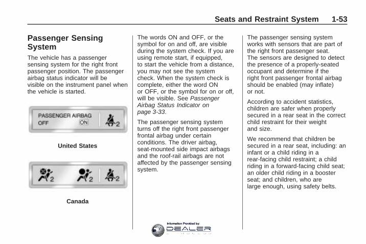
Passenger SensingSystemThe vehicle has a passengersensing system for the right frontpassenger position. The passengerairbag status indicator will bevisible on the instrument panel whenthe vehicle is started.
The words ON and OFF, or thesymbol for on and off, are visibleduring the system check. If you areusing remote start, if equipped,to start the vehicle from a distance,you may not see the systemcheck. When the system check iscomplete, either the word ONor OFF, or the symbol for on or off,will be visible. See PassengerAirbag Status Indicator onpage 3-33.
The passenger sensing systemturns off the right front passengerfrontal airbag under certainconditions. The driver airbag,seat-mounted side impact airbagsand the roof-rail airbags are notaffected by the passenger sensingsystem.
The passenger sensing systemworks with sensors that are part ofthe right front passenger seat.The sensors are designed to detectthe presence of a properly-seatedoccupant and determine if theright front passenger frontal airbagshould be enabled (may inflate)or not.
According to accident statistics,children are safer when properlysecured in a rear seat in the correctchild restraint for their weightand size.
We recommend that children besecured in a rear seat, including: aninfant or a child riding in arear-facing child restraint; a childriding in a forward-facing child seat;an older child riding in a boosterseat; and children, who arelarge enough, using safety belts.
United States
Canada
Seats and Restraint System 1-53
Information Provided by:

A label on the sun visor says,“Never put a rear-facing child seatin the front.” This is because the riskto the rear-facing child is so great,if the airbag deploys.
{ CAUTION
A child in a rear-facing childrestraint can be seriously injuredor killed if the right front passengerairbag inflates. This is becausethe back of the rear-facing childrestraint would be very close tothe inflating airbag. A child in aforward-facing child restraint canbe seriously injured or killed ifthe right front passenger airbaginflates and the passenger seat isin a forward position.
Even if the passenger sensingsystem has turned off the rightfront passenger frontal airbag, no
(Continued)
CAUTION (Continued)
system is fail-safe. No one canguarantee that an airbag will notdeploy under some unusualcircumstance, even though theairbag is turned off.
Secure rear-facing child restraintsin a rear seat, even if the airbag isoff. If you secure a forward-facingchild restraint in the right front seat,always move the front passengerseat as far back as it will go. It isbetter to secure the child restraintin a rear seat.
The passenger sensing system isdesigned to turn off the rightfront passenger frontal airbag if:
• The right front passenger seat isunoccupied.
• The system determines that aninfant is present in a childrestraint.
• A right front passenger takeshis/her weight off of the seat for aperiod of time.
• Or, if there is a critical problemwith the airbag system or thepassenger sensing system.
When the passenger sensingsystem has turned off the right frontpassenger frontal airbag, the offindicator will light and stay litto remind you that the airbag is off.See Passenger Airbag StatusIndicator on page 3-33.
The passenger sensing system isdesigned to turn on (may inflate) theright front passenger frontal airbaganytime the system senses that aperson of adult size is sitting properlyin the right front passenger seat.
When the passenger sensingsystem has allowed the airbag to beenabled, the on indicator will lightand stay lit to remind you thatthe airbag is active.
1-54 Seats and Restraint System
Information Provided by:

For some children, including childrenin child restraints, and for very smalladults, the passenger sensingsystem may or may not turn off theright front passenger frontal airbag,depending upon the person’s seatingposture and body build. Everyone inthe vehicle who has outgrown childrestraints should wear a safety beltproperly — whether or not there is anairbag for that person.
{ CAUTION
If the airbag readiness light evercomes on and stays on, it meansthat something may be wrong withthe airbag system. To help avoidinjury to yourself or others, havethe vehicle serviced right away.See Airbag Readiness Light onpage 3-33 for more information,including important safetyinformation.
If the On Indicator is Lit for aChild RestraintIf a child restraint has been installedand the on indicator is lit:
1. Turn the vehicle off.
2. Remove the child restraint fromthe vehicle.
3. Remove any additional itemsfrom the seat such as blankets,cushions, seat covers, seatheaters, or seat massagers.
4. Reinstall the child restraintfollowing the directions providedby the child restraintmanufacturer and refer toSecuring a Child Restraint in theRight Front Seat Position onpage 1-43.
5. If, after reinstalling the childrestraint and restarting thevehicle, the on indicator is still lit,turn the vehicle off. Thenslightly recline the vehicleseatback and adjust the seatcushion, if adjustable, tomake sure that the vehicleseatback is not pushing the childrestraint into the seat cushion.Also make sure the child restraintis not trapped under the vehiclehead restraint. If this happens,adjust the head restraint.See Head Restraints onpage 1-2.
6. Restart the vehicle.The passenger sensing systemmay or may not turn off theairbag for a child in a childrestraint depending upon thechild’s seating posture and bodybuild. It is better to secure thechild restraint in a rear seat.
Seats and Restraint System 1-55
Information Provided by:

If the Off Indicator is Lit for anAdult-Size Occupant
If a person of adult-size is sitting inthe right front passenger seat, butthe off indicator is lit, it could bebecause that person is not sittingproperly in the seat. If this happens,use the following steps to allow thesystem to detect that person andenable the right front passengerfrontal airbag:1. Turn the vehicle off.2. Remove any additional material
from the seat, such as blankets,cushions, seat covers, seatheaters, or seat massagers.
3. Place the seatback in the fullyupright position.
4. Have the person sit upright in theseat, centered on the seatcushion, with legs comfortablyextended.
5. Restart the vehicle and have theperson remain in this position fortwo to three minutes after theon indicator is lit.
Additional Factors AffectingSystem OperationSafety belts help keep thepassenger in position on the seatduring vehicle maneuvers andbraking, which helps the passengersensing system maintain thepassenger airbag status. See“Safety Belts” and “Child Restraints”in the Index for additionalinformation about the importance ofproper restraint use.
A thick layer of additional material,such as a blanket or cushion, oraftermarket equipment such as seatcovers, seat heaters, and seat
massagers can affect how well thepassenger sensing systemoperates. We recommend that younot use seat covers or otheraftermarket equipment except whenapproved by GM for your specificvehicle. See Adding Equipmentto Your Airbag-Equipped Vehicle onpage 1-58 for more informationabout modifications that can affecthow the system operates.
A wet seat can affect theperformance of the passengersensing system. Here is how:
• The passenger sensing systemmay turn off the passenger airbagwhen liquid is soaked into theseat. If this happens, the offindicator will be lit, and the airbagreadiness light on the instrumentpanel will also be lit.
1-56 Seats and Restraint System
Information Provided by:

• Liquid pooled on the seat that hasnot soaked in may make it morelikely that the passenger sensingsystem will enable (turn on) thepassenger airbag while a childrestraint or child occupant is onthe seat. If the passenger airbagis turned on, the on indicator willbe lit.
If the passenger seat gets wet, drythe seat immediately. If the airbagreadiness light is lit, do not install achild restraint or allow anyone tooccupy the seat. See AirbagReadiness Light on page 3-33 forimportant safety information.
The on indicator may be lit if anobject, such as a briefcase,handbag, grocery bag, laptop orother electronic device, is put on anunoccupied seat. If this is not desiredremove the object from the seat.
{ CAUTION
Stowing of articles under thepassenger seat or between thepassenger seat cushion andseatback may interfere with theproper operation of the passengersensing system.
Servicing YourAirbag-Equipped VehicleAirbags affect how the vehicleshould be serviced. There are partsof the airbag system in severalplaces around the vehicle. Yourdealer/retailer and the servicemanual have information aboutservicing the vehicle and the airbagsystem. To purchase a servicemanual, see Service PublicationsOrdering Information on page 7-15.
{ CAUTION
For up to 10 seconds after theignition is turned off and thebattery is disconnected, an airbagcan still inflate during improperservice. You can be injured if youare close to an airbag when itinflates. Avoid yellow connectors.They are probably part of theairbag system. Be sure to followproper service procedures, andmake sure the person performingwork for you is qualified to do so.
Seats and Restraint System 1-57
Information Provided by:

Adding Equipment toYour Airbag-EquippedVehicleQ: Is there anything I might add
to or change about thevehicle that could keep theairbags from workingproperly?
A: Yes. If you add things thatchange the vehicle’s frame,bumper system, height, front endor side sheet metal, they maykeep the airbag system fromworking properly. Changing ormoving any parts of the frontseats, safety belts, the airbagsensing and diagnostic module,steering wheel, instrumentpanel, roof-rail airbag modules,ceiling headliner or pillargarnish trim, front sensors, sideimpact sensors, rolloversensor module, or airbag wiringcan affect the operation ofthe airbag system.
In addition, the vehicle has apassenger sensing system for theright front passenger position,which includes sensors that arepart of the passenger seat. Thepassenger sensing system maynot operate properly if the originalseat trim is replaced with non-GMcovers, upholstery or trim, or withGM covers, upholstery or trimdesigned for a different vehicle.Any object, such as anaftermarket seat heater or acomfort enhancing pad or device,installed under or on top of theseat fabric, could also interferewith the operation of thepassenger sensing system. Thiscould either prevent properdeployment of the passengerairbag(s) or prevent thepassenger sensing system fromproperly turning off the passengerairbag(s). See PassengerSensing System on page 1-53.
If you have questions, callCustomer Assistance. The phonenumbers and addresses forCustomer Assistance arein Step Two of the CustomerSatisfaction Procedure inthis manual. See CustomerSatisfaction Procedure onpage 7-1.
If the vehicle has rolloverroof-rail airbags, see DifferentSize Tires and Wheels onpage 5-52 for additionalimportant information.
1-58 Seats and Restraint System
Information Provided by:

Q: Because I have a disability, Ihave to get my vehiclemodified. How can I find outwhether this will affect myairbag system?
A: If you have questions, callCustomer Assistance. The phonenumbers and addresses forCustomer Assistance arein Step Two of the CustomerSatisfaction Procedure inthis manual. See CustomerSatisfaction Procedure onpage 7-1.
In addition, your dealer/retailerand the service manual haveinformation about the location ofthe airbag sensors, sensingand diagnostic module and airbagwiring.
Restraint SystemCheck
Checking the RestraintSystemsSafety BeltsNow and then, check that the safetybelt reminder light, safety belts,buckles, latch plates, retractors, andanchorages are all workingproperly.
Look for any other loose ordamaged safety belt system partsthat might keep a safety belt systemfrom doing its job. See yourdealer/retailer to have it repaired.Torn or frayed safety belts may notprotect you in a crash. They canrip apart under impact forces.If a belt is torn or frayed, get a newone right away.
Make sure the safety belt reminderlight is working. See Safety BeltReminders on page 3-32 for moreinformation.
Keep safety belts clean and dry.See Care of Safety Belts onpage 5-80.
AirbagsThe airbag system does not needregularly scheduled maintenance orreplacement. Make sure theairbag readiness light is working.See Airbag Readiness Lighton page 3-33 for more information.
Notice: If an airbag coveringis damaged, opened, or broken,the airbag may not work properly.Do not open or break the airbagcoverings. If there are any openedor broken airbag covers, havethe airbag covering and/or airbagmodule replaced. For thelocation of the airbag modules,see What Makes an AirbagInflate? on page 1-51. See yourdealer/retailer for service.
Seats and Restraint System 1-59
Information Provided by:

Replacing RestraintSystem Parts After aCrash
{ CAUTION
A crash can damage the restraintsystems in your vehicle. Adamaged restraint system maynot properly protect the personusing it, resulting in serious injuryor even death in a crash. To helpmake sure your restraint systemsare working properly after a crash,have them inspected and anynecessary replacements made assoon as possible.
If the vehicle has been in a crash, doyou need new safety belts or LATCHsystem (if equipped) parts?
After a very minor crash, nothingmay be necessary. But thesafety belt assemblies that wereused during any crash mayhave been stressed or damaged.
See your dealer/retailer to have thesafety belt assemblies inspectedor replaced.
If the vehicle has the LATCHsystem and it was being usedduring a crash, you may neednew LATCH system parts.
New parts and repairs may benecessary even if the safety beltor LATCH system (if equipped),was not being used at the time ofthe crash.
If an airbag inflates, you will need toreplace airbag system parts. Seethe part on the airbag system earlierin this section.
Have the safety belt pretensionerschecked if the vehicle has been in acrash, if the airbag readiness lightstays on after the vehicle is started,or while you are driving. SeeAirbag Readiness Light onpage 3-33.
1-60 Seats and Restraint System
Information Provided by:

Features andControls
KeysKeys ...................................2-2Remote Keyless Entry(RKE) System .....................2-3
Remote Keyless Entry(RKE) System Operation .......2-4
Remote Vehicle Start .............2-6
Doors and LocksDoor Locks ..........................2-8Power Door Locks .................2-8Delayed Locking ...................2-8Programmable AutomaticDoor Locks .........................2-9
Rear Door Security Locks .......2-9Lockout Protection .................2-9Liftgate ...............................2-10Power Liftgate .....................2-11
WindowsWindows ............................2-14Power Windows ..................2-14Sun Visors .........................2-16
Theft-Deterrent SystemsTheft-Deterrent Systems .......2-16Content Theft-Deterrent ........2-16PASS-Key® III+ ElectronicImmobilizer .......................2-18
PASS-Key® III+ ElectronicImmobilizer Operation .........2-18
Starting and Operating YourVehicleNew Vehicle Break-In ...........2-20Ignition Positions .................2-21Retained AccessoryPower (RAP) .....................2-22
Starting the Engine ..............2-22Engine Coolant Heater .........2-23Automatic TransmissionOperation ..........................2-24
Tow/Haul Mode ...................2-26Parking Brake .....................2-27Shifting Into Park .................2-28Shifting Out of Park .............2-29Parking Over ThingsThat Burn .........................2-29
Engine Exhaust ...................2-30Running the Vehicle WhileParked .............................2-30
MirrorsManual Rearview Mirror ........2-31Automatic DimmingRearview Mirror .................2-31
Outside Power Mirrors ..........2-32Outside Power FoldawayMirrors .............................2-33
Blind Spot Mirrors ................2-34Park Tilt Mirrors ..................2-35Outside Convex Mirror ..........2-35Outside Heated Mirrors .........2-35
Object Detection SystemsUltrasonic Rear ParkingAssist (URPA) ...................2-36
Rear VisionCamera (RVC) ...................2-38
OnStar® SystemOnStar® System ..................2-43
Universal Home RemoteSystemUniversal Home RemoteSystem .............................2-47
Universal Home RemoteSystem Operation ..............2-47
Features and Controls 2-1
Information Provided by:

Storage AreasGlove Box ..........................2-52Cupholders .........................2-52Instrument Panel Storage ......2-52Center Console Storage .......2-52Second Row CenterConsole ............................2-53
Floor Mats ..........................2-54Luggage Carrier ..................2-54Convenience Net .................2-55Cargo Cover .......................2-55Cargo Tie Downs ................2-55Cargo ManagementSystem .............................2-55
SunroofSunroof ..............................2-56
Keys
{ CAUTION
Leaving children in a vehicle withthe ignition key is dangerous formany reasons, children or otherscould be badly injured or evenkilled. They could operate thepower windows or other controlsor even make the vehicle move.The windows will function with thekeys in the ignition and childrencould be seriously injured or killedif caught in the path of a closingwindow. Do not leave the keys ina vehicle with children.
The key is used for the ignition andall door locks.
The key has a bar-coded key tagthat the dealer/retailer or qualifiedlocksmith can use to make newkeys. Store this information in a safeplace, not in the vehicle.
See your dealer/retailer if areplacement key or additional key isneeded.
Notice: If you ever lock yourkeys in the vehicle, you may haveto damage the vehicle to get in.Be sure you have spare keys.
2-2 Features and Controls
Information Provided by:

If you are locked out of the vehicle,call the Roadside AssistanceCenter. See Roadside AssistanceProgram on page 7-6.
Remote Keyless Entry(RKE) SystemThe Remote Keyless Entry (RKE)system operates on a radiofrequency subject to FederalCommunications Commission (FCC)Rules and with Industry Canada.
This device complies with Part 15 ofthe FCC Rules. Operation is subjectto the following two conditions:
1. This device may not causeinterference.
2. This device must accept anyinterference received, includinginterference that may causeundesired operation of thedevice.
This device complies with RSS-210of Industry Canada. Operation issubject to the following twoconditions:
1. This device may not causeinterference.
2. This device must accept anyinterference received, includinginterference that may causeundesired operation of thedevice.
Changes or modifications tothis system by other than anauthorized service facility could voidauthorization to use this equipment.
If there is a decrease in the RKEoperating range, try this:
• Check the distance. Thetransmitter may be too far fromthe vehicle. Stand closerduring rainy or snowy weather.
• Check the location. Othervehicles or objects may beblocking the signal. Take a fewsteps to the left or right, holdthe transmitter higher, andtry again.
• Check the transmitter’s battery.See “Battery Replacement”later in this section.
• If the transmitter is still notworking correctly, see yourdealer/retailer or a qualifiedtechnician for service.
Features and Controls 2-3
Information Provided by:

Remote Keyless Entry(RKE) System OperationThe Remote Keyless Entry (RKE)transmitter functions work up to195 feet (60 m) away from thevehicle.
There are other conditions whichcan affect the performance ofthe transmitter. See Remote KeylessEntry (RKE) System on page 2-3.
/ (Remote Vehicle Start): Forvehicles with this feature, seeRemote Vehicle Start on page 2-6for additional information.
Q (Lock): Press to lock all thedoors.
If enabled through the DriverInformation Center (DIC), theparking lamps flash once to indicatelocking has occurred. If enabledthrough the DIC, the horn soundswhen Q is pressed again withinfive seconds. See DIC VehicleCustomization (With DIC Buttons)on page 3-65 for additionalinformation.
Pressing Q may arm the contenttheft-deterrent system. See ContentTheft-Deterrent on page 2-16.
K (Unlock): Press once to unlockonly the driver door. If K ispressed again within five seconds,all remaining doors unlock. Theinterior lamps come on and stay onfor 20 seconds or until the ignitionis turned on.
If enabled through the DIC,the parking lamps flash twice toindicate unlocking has occurred.See DIC Vehicle Customization(With DIC Buttons) on page 3-65.
Pressing K on the RKE transmitterdisarms the content theft-deterrentsystem. See Content Theft-Deterrenton page 2-16.
& (Power Liftgate): Press andhold for about one second toopen and close the liftgate.The taillamps flash and a chimesounds to indicate when the liftgateis opening and closing.With Remote Start and Liftgate
(Without Remote Start orLiftgate Similar)
2-4 Features and Controls
Information Provided by:

L (Vehicle Locator/Panic Alarm):Press and release to locate thevehicle. The parking lamps flash andthe horn sounds three times.
Press and hold L for more thantwo seconds to activate thepanic alarm. The parking lampsflash and the horn soundsrepeatedly for 30 seconds. Thealarm turns off when the ignition ismoved to ON/RUN or L ispressed again. The ignition must bein LOCK/OFF for the panic alarmto work.
Programming Transmitters tothe VehicleOnly RKE transmitters programmedto this vehicle will work. If atransmitter is lost or stolen, areplacement can be purchased andprogrammed through your dealer/retailer. When the replacementtransmitter is programmed to thisvehicle using the DIC, all remainingtransmitters must also bereprogrammed. Any lost or stolen
transmitters will no longer work oncethe new transmitter is programmed.Each vehicle can have up toeight transmitters programmed to it.See “Relearn Remote Key” underDIC Operation and Displays(With DIC Buttons) on page 3-45or DIC Operation and Displays(Without DIC Buttons) on page 3-51for instructions on how to programtransmitters to this vehicle.
Battery ReplacementReplace the battery if the REPLACEBATTERY IN REMOTE KEYmessage displays in the DIC.
Notice: When replacing thebattery, do not touch any of thecircuitry on the transmitter.Static from your body coulddamage the transmitter.
1. Separate the transmitter with aflat, thin object inserted into thenotch on the side.
2. Remove the old battery. Do notuse a metal object.
3. Insert the new battery, positiveside facing down. Replace witha CR2032 or equivalent battery.
4. Snap the transmitter backtogether.
Features and Controls 2-5
Information Provided by:

Remote Vehicle StartThis vehicle may have a remotestarting feature that starts the enginefrom outside of the vehicle.
If the vehicle has an automaticclimate control system, the climatecontrol system defaults to aheating or cooling mode dependingon the outside temperatures.If the vehicle does not have anautomatic climate control system,the system turns on at thesetting the vehicle was set to whenthe vehicle was last turned off.
If the vehicle has an automaticclimate control system and heatedseats, the heated seats turn onduring colder outside temperaturesand shut off when the key isturned to ON/RUN. See HeatedSeats on page 1-5 or Heated andCooled Seats on page 1-5 formore information.
The rear window defogger andheated mirrors, if the vehicle hasthem, turn on during colder outsidetemperatures and turn off whenthe key is turned to ON/RUN.
Laws in some communities mayrestrict the use of remote starters.For example, some laws mayrequire a person using the remotestart to have the vehicle in viewwhen doing so. Check localregulations for any requirements onremote starting of vehicles.
Do not use the remote start featureif the vehicle is low on fuel. Thevehicle could run out of fuel.
If the vehicle has the remote startfeature, the RKE transmitterfunctions have an increased rangeof operation. However, the rangemay be less while the vehicleis running.
There are other conditions whichcan affect the performance ofthe transmitter, see Remote KeylessEntry (RKE) System on page 2-3for additional information.
/ (Remote Start): This button islocated on the RKE transmitter if thevehicle has remote start.
To start the vehicle:
1. Aim the transmitter at thevehicle.
2. Press and release Q, thenimmediately press and hold/ until the parking lamps flash.If the vehicle’s lights can notbe seen, press and hold / for atleast four seconds. Thevehicle’s doors lock. When thevehicle starts, the parkinglamps turn on and remain onwhile the vehicle is running.
Pressing / again, after thevehicle has started, shuts thevehicle off.
2-6 Features and Controls
Information Provided by:

3. If it is the first remote start sincethe vehicle has been driven,repeat these steps while theengine is still running, to extendthe time by 10 minutes forthe engine to continue to run.Remote start can be extendedone time.
After entering the vehicle during aremote start, insert and turn the keyto the ON/RUN position to drivethe vehicle.
If the vehicle is left running itautomatically shuts off after10 minutes unless a time extensionhas been done.
To manually shut off a remote start:
• Aim the RKE transmitter at thevehicle and press / until theparking lamps turn off.
• Turn on the hazard warningflashers.
• Turn the ignition switch on andthen off.
The vehicle can be started using theremote start feature two separatetimes between driving sequences.The engine runs for 10 minutes aftereach remote start. Or, the enginerun time can be extended another10 minutes within the first 10 minuteremote start time frame, and beforethe engine stops.
For example, if Q and then / arepressed again after the vehiclehas been running for five minutes,10 minutes are added, allowingthe engine to run for 15 minutes.
The additional 10 minutes areconsidered a second remote start.
The vehicle must be started with thekey once two remote starts, or asingle remote start with one timeextension has been done.
The vehicle can be started using theremote start feature again afterthe key is removed from the ignition.
The vehicle cannot be started usingthe remote start feature if the keyis in the ignition, the hood is open,or if there is an emission controlsystem malfunction.
The engine turns off during aremote start if the coolanttemperature gets too high or if theoil pressure gets low.
Vehicles that have the remotevehicle start feature are shipped fromthe factory with the remote vehiclestart system enabled. The systemmay be enabled or disabled throughthe DIC if the vehicle has DICbuttons. See “REMOTE START”under DIC Vehicle Customization(With DIC Buttons) on page 3-65 foradditional information. If the vehicledoes not have DIC buttons, see yourdealer/retailer to enable or disablethe remote start system.
Features and Controls 2-7
Information Provided by:

Doors and Locks
Door Locks
{ CAUTION
Unlocked doors can bedangerous.
• Passengers, especiallychildren, can easily open thedoors and fall out of a movingvehicle. When a door islocked, the handle will notopen it. The chance of beingthrown out of the vehicle in acrash is increased if thedoors are not locked. So, allpassengers should wearsafety belts properly and thedoors should be lockedwhenever the vehicle isdriven.
(Continued)
CAUTION (Continued)
• Young children who get intounlocked vehicles may beunable to get out. A child canbe overcome by extreme heatand can suffer permanentinjuries or even death fromheat stroke. Always lock thevehicle whenever leaving it.
• Outsiders can easily enterthrough an unlocked doorwhen you slow down or stopyour vehicle. Locking yourdoors can help prevent thisfrom happening.
To lock or unlock a door, use thekey from the outside or the door lockfrom the inside.
Power Door LocksThe power door lock switches arelocated on the front doors.
" (Unlock): Press to unlock thedoors.
Q (Lock): Remove the key fromthe ignition and press to lockthe doors.
Delayed LockingWhen locking the doors with thepower lock switch and a door or theliftgate is open, the doors will lockfive seconds after the last dooris closed. You will hear three chimesto signal that the delayed lockingfeature is in use.
Pressing the power lock switchtwice or the lock button on the RKEtransmitter twice will override thedelayed locking feature andimmediately lock all the doors.
2-8 Features and Controls
Information Provided by:

This feature will not operate if thekey is in the ignition.
This feature can be programmed byusing the Driver Information Center(DIC). See “DELAY DOOR LOCK”under DIC Vehicle Customization(With DIC Buttons) on page 3-65.
Programmable AutomaticDoor LocksVehicles with an automaticlock/unlock feature enable you toprogram the vehicle’s powerdoor locks. This feature can beprogrammed through the DriverInformation Center (DIC). See DICVehicle Customization (With DICButtons) on page 3-65 for moreinformation.
Rear Door SecurityLocksThe vehicle has rear door securitylocks to prevent passengersfrom opening the rear doors fromthe inside.
Open the rear doors to access thesecurity locks on the inside edgeof each door.
To set the locks, insert a key intothe slot and turn it to the horizontalposition. The door can only beopened from the outside with thedoor unlocked. To return the door tonormal operation, turn the slot tothe vertical position.
Lockout ProtectionThis feature protects you fromlocking the key in the vehicle whenthe key is in the ignition and afront door is open.
If the driver side power door lockswitch is pressed when the driver’sdoor is open and the key is in theignition, all of the doors will lock andthen the driver door will unlock.
If the passenger side power doorlock switch is pressed when the frontpassenger door is open and thekey is in the ignition, all of the doorswill lock and then the frontpassenger door will unlock.
Features and Controls 2-9
Information Provided by:

Liftgate
{ CAUTION
Exhaust gases can enter thevehicle if it is driven with theliftgate, trunk/hatch open, or withany objects that pass through theseal between the body and thetrunk/hatch or liftgate. Engineexhaust contains CarbonMonoxide (CO) which cannot beseen or smelled. It can causeunconsciousness and even death.
If the vehicle must be driven withthe liftgate, or trunk/hatch open:
• Close all of the windows.• Fully open the air outlets on
or under the instrumentpanel.
(Continued)
CAUTION (Continued)
• Adjust the Climate Controlsystem to a setting thatbrings in only outside air andset the fan speed to thehighest setting. See ClimateControl System in the Index.
• If the vehicle is equipped witha power liftgate, disable thepower liftgate function.
For more information aboutcarbon monoxide, see EngineExhaust on page 2-30.
If the vehicle has a power liftgate,see Power Liftgate on page 2-11.
To unlock the liftgate, use the powerdoor lock switch or press the doorunlock button on the RKE transmittertwice. See Remote Keyless Entry(RKE) System Operation onpage 2-4.
To open the liftgate, press thetouchpad on the underside of theliftgate handle. The vehicle must bein P (Park) to open the liftgate.To close the liftgate, use the pull cupor strap.
The liftgate has an electric latch.If the battery is disconnected or haslow voltage, the liftgate will notopen. The liftgate will resumeoperation when the battery isreconnected and charged.
If the battery is properly connectedand has adequate voltage, andthe liftgate still will not function,the vehicle should be takento a dealers/retailer for service.
2-10 Features and Controls
Information Provided by:

Power LiftgatePower Liftgate Operation
{ CAUTION
Exhaust gases can enter thevehicle if it is driven with theliftgate, trunk/hatch open, or withany objects that pass through theseal between the body and thetrunk/hatch or liftgate. Engineexhaust contains CarbonMonoxide (CO) which cannot beseen or smelled. It can causeunconsciousness and even death.
If the vehicle must be driven withthe liftgate, or trunk/hatch open:
• Close all of the windows.• Fully open the air outlets on
or under the instrumentpanel.
(Continued)
CAUTION (Continued)
• Adjust the Climate Controlsystem to a setting thatbrings in only outside air andset the fan speed to thehighest setting. See ClimateControl System in the Index.
• If the vehicle is equipped witha power liftgate, disable thepower liftgate function.
For more information aboutcarbon monoxide, see EngineExhaust on page 2-30.
The vehicle may have a powerliftgate. The vehicle must bein P (Park) to use this feature.
The taillamps will flash and a chimewill sound when the power liftgateis used.
{ CAUTION
You or others could be injured ifcaught in the path of the powerliftgate. Make sure there is no onein the way of the liftgate as it isopening and closing.
Notice: If you open the liftgatewithout checking for overheadobstructions such as a garagedoor, you could damage theliftgate or the liftgate glass.Always check to make sure thearea above and behind the liftgateis clear before opening it.
The power liftgate can be poweropened and closed in thefollowing ways:
• Press and hold the power liftgatebutton on the RKE transmitteruntil the liftgate starts moving.Remote Keyless Entry (RKE)System Operation on page 2-4for more information.
Features and Controls 2-11
Information Provided by:
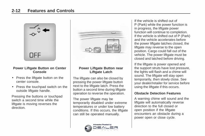
• Press the liftgate button on thecenter console.
• Press the touchpad switch on theoutside liftgate handle.
Pressing the buttons or touchpadswitch a second time while theliftgate is moving reverses thedirection.
The liftgate can also be closed bypressing the power liftgate buttonnext to the liftgate latch. Press thebutton a second time during liftgateoperation to reverse the operation.
The power liftgate may betemporarily disabled under extremetemperatures or under low batteryconditions. If this occurs, the liftgatecan still be operated manually.
If the vehicle is shifted out ofP (Park) while the power function isin progress, the liftgate powerfunction will continue to completion.If the vehicle is shifted out of P (Park)and the vehicle accelerates beforethe power liftgate latches closed, theliftgate may reverse to the openposition. Cargo could fall out of thevehicle. The power liftgate must beclosed and latched before driving.
If the liftgate is power opened andthe support struts have lost pressure,the lights will flash and a chime willsound. The liftgate will stay opentemporarily, then slowly close. Seeyour dealer/retailer for service beforeusing the liftgate if this occurs.
Obstacle Detection Features
A warning chime will sound and theliftgate will automatically reversedirection to the full closed oropen position if the liftgateencounters an obstacle during apower open or close cycle.
Power Liftgate Button on CenterConsole
Power Liftgate Button nearLiftgate Latch
2-12 Features and Controls
Information Provided by:

After removing the obstruction, thepower liftgate operation can beused again.
If the liftgate comes across moreobstacles on the same power cycle,the power function deactivates,and you must manually openor close the liftgate. A messagedisplays, LIFTGATE OPEN,to indicate that the liftgate is open.See Driver Information Center(DIC) on page 3-44 for moreinformation. After removing theobstructions, manually openthe liftgate to the full open positionor close the liftgate to the fullyclosed and latched position.The liftgate resumes normal poweroperation.
Pinch sensors are located on theside edges of the liftgate. If anobject is caught between the liftgateand the vehicle and pressesagainst this sensor, the liftgate willreverse direction and open fully.
The liftgate will remain open untilit is activated again or closedmanually. Do not force the liftgateopen or closed during a power cycle.
Manual Operation of PowerLiftgate
To change the liftgate to manualoperation, press the switch onthe center console to OFF.
With the power liftgate disabled andall of the doors unlocked, the liftgatecan be manually opened and closed.
To open the liftgate, press thetouchpad on the handle onthe outside of the liftgate and lift thegate open. To close the liftgate,use the pull cup to lower the liftgateand close. The liftgate latch willpower close. Always close theliftgate before driving.
If the RKE button or the power closebutton on the liftgate is pressed whilepower operation is disabled, thelights will flash three times, but theliftgate will not move.
It is not recommended that youdrive with the liftgate open.However, if you must drive with theliftgate open, the liftgate shouldbe set to manual operation bypressing the OFF switch on thecenter console.
Features and Controls 2-13
Information Provided by:

Windows
{ CAUTION
Leaving children, helpless adults,or pets in a vehicle with thewindows closed is dangerous.They can be overcome by theextreme heat and sufferpermanent injuries or even deathfrom heat stroke. Never leave achild, a helpless adult, or a petalone in a vehicle, especially withthe windows closed in warm orhot weather.
Power Windows
{ CAUTION
Leaving children in a vehicle withthe keys is dangerous for manyreasons, children or others couldbe badly injured or even killed.They could operate the powerwindows or other controls or evenmake the vehicle move. Thewindows will function and theycould be seriously injured or killedif caught in the path of a closingwindow. Do not leave keys in avehicle with children.
When there are children in therear seat use the window lockoutbutton to prevent unintentionaloperation of the windows.
2-14 Features and Controls
Information Provided by:

The power window controls arelocated on each of the side doors.
The driver door also has switchesthat control the passengerand rear windows. The powerwindows work with the ignition inACC/ACCESSORY, ON/RUN orwhen Retained Accessory Power(RAP) is active. See RetainedAccessory Power (RAP) onpage 2-22.
Press the switch to lower thewindow. Pull up on the front edge ofthe switch to raise the window.
Express-Down WindowsThe express-down feature allowsthe windows to be lowered withoutholding the switch. Press thewindow switch fully and release it toactivate the express-down feature.The express mode can be canceledby pressing or pulling the switch.
Express-Up WindowThe express-up feature allows thewindows to be raised all the waywithout holding the switch up.Pull the switch up fully and release itto activate the express-up feature.The express-up mode can becanceled by pressing or pullingthe switch.
Programming the PowerWindowsIf the battery on the vehicle hasbeen recharged, disconnected, orreplaced, windows with theexpress-up feature need to bereprogrammed for this feature towork. To program the window:
1. Close all doors with the ignition inthe ACC/ACCESSORY, ON/RUNposition, or when RetainedAccessory Power (RAP) is active.See Retained Accessory Power(RAP) on page 2-22.
2. Press and continue to hold thewindow switch until the windowis fully open.
3. Pull up and hold the windowswitch to close the window.Continue to hold it briefly afterthe window is fully closed.
4. Repeat for each window that hasthe express-up feature.
Uplevel shown, base similar
Features and Controls 2-15
Information Provided by:

Anti-Pinch FeatureThe anti-pinch feature is on windowswith the express-up feature. If anobject is in the way of the window asit is express-closing, or in certainweather conditions like severeicing, the window will stop andopen to a factory preset position.The window functions normally oncethe obstruction is removed.
Window Lockout
o (Window Lockout): Thewindow lockout switch is locatedwith the power window switcheson the driver door armrest. Thisfeature prevents the rear passengerwindows from operating thewindows, except from the driverposition. Press the switch to turn thelockout feature on or off. An indicatorlight will come on to show the lockoutfeature is on.
Sun VisorsPull the sun visor down to blockglare. Detach the sun visor from thecenter mount and slide it alongthe rod from side-to-side to coverthe driver or passenger side ofthe front window. Swing thesun visor to the side to cover theside window. It can be moved alongthe rod from side-to-side in thisposition also.
Lighted Visor Vanity MirrorThe vehicle has lighted visor vanitymirrors on both the driver andpassenger sun visors. Pull the sunvisor down and lift the mirrorcover to turn the lamps on.
Theft-DeterrentSystemsVehicle theft is big business,especially in some cities. Thisvehicle has theft-deterrent features,however, they do not make itimpossible to steal.
Content Theft-DeterrentThis vehicle may have a contenttheft-deterrent alarm system.
To activate the theft-deterrentsystem, do one of the following:
• Press Q on the Remote KeylessEntry (RKE) transmitter or thepower door lock switch when anydoor is open.
The security light flashes.
2-16 Features and Controls
Information Provided by:

When the door is closed, thesecurity light stops flashing andstays on solid for approximately30 seconds. The contenttheft deterrent alarm is not armeduntil the security light goes off.If the delayed locking feature isactive, the alarm is not activateduntil all doors are closed and thesecurity light goes off.
• Press Q when the driver door isclosed. The security light comeson solid for approximately30 seconds and then goes off.The content theft deterrent alarmis not armed until the security lightgoes off.
The theft-deterrent system will notactivate if the doors are lockedwith the vehicle’s key or the manualdoor lock.
If a locked door is opened withoutusing the RKE transmitter, aten second pre-alarm occurs.The horn chirps and the lights flash.
If the key is not placed in theignition and turned to START orthe door is not unlocked bypressing Q during the ten secondpre-alarm, the alarm goes off.The headlamps flash and the hornsounds for about two minutes,then turns off to save the batterypower.
The vehicle can be started with thecorrect ignition key if the alarmhas been set off.
To avoid setting off the alarm byaccident:
• Lock the vehicle with the doorkey after the doors are closed.
• Unlock the door with the RKEtransmitter. Unlocking a doorany other way sets off the alarmif the system has been armed.
Press K or place the key in theignition and turn it to START to turnoff the alarm.
Testing the AlarmTo test the alarm:
1. From inside the vehicle, lowerthe driver side window andopen the driver door.
2. Press Q.
3. Get out of the vehicle, close thedoor and wait for the securitylight to go out.
4. Then reach in through thewindow, unlock the door with themanual door lock and open thedoor. This should set off thealarm.
If the alarm does not sound when itshould, but the vehicle’s headlampsflash, check to see if the hornworks. The horn fuse may be blown.To replace the fuse, see Fusesand Circuit Breakers on page 5-86.
If the alarm does not sound or thevehicle’s headlamps do not flash,see your dealer/retailer for service.
Features and Controls 2-17
Information Provided by:
PASS-Key® III+ ElectronicImmobilizerThe PASS-Key III+ systemoperates on a radio frequencysubject to Federal CommunicationsCommission (FCC) Rules andwith Industry Canada.
This device complies with Part 15 ofthe FCC Rules. Operation is subjectto the following two conditions:
1. This device may not causeharmful interference.
2. This device must accept anyinterference received, includinginterference that may causeundesired operation.
This device complies with RSS-210of Industry Canada. Operation issubject to the following twoconditions:
1. This device may not causeinterference.
2. This device must accept anyinterference received, includinginterference that may causeundesired operation of thedevice.
Changes or modifications to thissystem by other than an authorizedservice facility could voidauthorization to use this equipment.
PASS-Key III+ uses a radiofrequency transponder in the keythat matches a decoder in thevehicle.
PASS-Key® III+ ElectronicImmobilizer OperationThis vehicle has PASS-Key® III+(Personalized Automotive SecuritySystem) theft-deterrent system.PASS-Key® III+ is a passivetheft-deterrent system.
The system is automatically armedwhen the key is removed fromthe ignition.
The system is automaticallydisarmed when the key is turned toON/RUN, ACC/ACCESSORY orSTART from the LOCK/OFF position.
You do not have to manually arm ordisarm the system.
The security light comes on if there isa problem with arming or disarmingthe theft-deterrent system.
2-18 Features and Controls
Information Provided by:

When the PASS-Key® III+ systemsenses an incorrect key, the vehicledoes not start. Anyone using atrial-and-error method to start thevehicle will be discouraged becauseof the high number of electrical keycodes.
If the engine does not start and thesecurity light on the instrument panelcomes on when trying to start thevehicle, there may be a problem withyour theft-deterrent system. Turn theignition off and try again.
If the engine still does not start, andthe key appears to be undamaged,try another ignition key and check thefuses. See Fuses and CircuitBreakers on page 5-86 for additionalinformation. If the engine still doesnot start with the other key, thevehicle needs service. If the vehicledoes start, the first key may be faulty.
See your dealer/retailer who canservice the PASS-Key® III+ to have anew key made. In an emergency,contact Roadside Assistance.See Roadside Assistance Programon page 7-6.
It is possible for the PASS-Key® III+decoder to learn the transpondervalue of a new or replacement key.Up to 10 keys may be programmedto the vehicle. The followingprocedure is for programmingadditional keys only. If all thecurrently programmed keys are lostor do not operate, you must seeyour dealer/retailer or a locksmithwho can service PASS-Key® III+ tohave keys made and programmedto the system.
See your dealer/retailer or alocksmith who can servicePASS-Key® III+ to get a new keyblank that is cut exactly as theignition key that operates thesystem.
To program the new additional key:
1. Verify that the new key hasa 1 stamped on it.
2. Insert the already programmedkey in the ignition and start theengine. If the engine does notstart, see your dealer/retailer forservice.
3. After the engine has started, turnthe key to LOCK/OFF, andremove the key.
4. Insert the key to be programmedand turn it to the ON/RUNposition within five seconds ofthe original key being turnedto the LOCK/OFF position.The security light turns off oncethe key has been programmed.
5. Repeat Steps 1 through 4if additional keys are to beprogrammed.
Features and Controls 2-19
Information Provided by:

If the PASS-Key® III+ key is lost ordamaged, see your dealer/retaileror a locksmith to have a newkey made.
The SERVICE THEFT DETERRENTSYSTEM message displays onthe Driver Information Center (DIC)when there is a problem with thetheft-deterrent system. See DICWarnings and Messages onpage 3-56 for additional information.
Do not leave the key or devicethat disarms or deactivates the theftdeterrent system in the vehicle.
Starting andOperating YourVehicle
New Vehicle Break-InNotice: The vehicle doesnot need an elaborate break-in.But it will perform better inthe long run if you follow theseguidelines:
• If you have all-wheel drive,keep your speed at 55 mph(88 km/h) or less for thefirst 500 miles (805 km).
• Do not drive at any oneconstant speed, fast or slow,for the first 500 miles (805 km).Do not make full-throttlestarts. Avoid downshifting tobrake or slow the vehicle.
• Avoid making hard stops forthe first 200 miles (322 km)or so. During this time thenew brake linings are not yetbroken in. Hard stops with newlinings can mean prematurewear and earlier replacement.Follow this breaking-inguideline every time you getnew brake linings.
• Do not tow a trailer duringbreak-in. See Towing aTrailer on page 4-25 for thetrailer towing capabilitiesof your vehicle and moreinformation.
Following break-in, engine speedand load can be graduallyincreased.
2-20 Features and Controls
Information Provided by:

Ignition Positions
The ignition switch has four differentpositions.
In order to shift out of P (Park),the ignition must be in ON/RUN orACC/ACCESSORY and thebrake pedal must be applied.
Notice: Using a tool to force thekey to turn in the ignition couldcause damage to the switch orbreak the key. Use the correct key,make sure it is all the way in, andturn it only with your hand. If thekey cannot be turned by hand,see your dealer/retailer.
( (LOCK/OFF): This position locksthe ignition and transmission. Thekey can be removed in LOCK/OFF.
The shift lever must be in P (Park)to turn the ignition switch toLOCK/OFF.
The steering can bind with thewheels turned off center. If thishappens, move the steering wheelfrom right to left while turningthe key to ACC/ACCESSORY.If this doesn’t work, then the vehicleneeds service.
ACC (ACC/ACCESSORY): This isthe position in which you can operatethe electrical accessories or itemsplugged into the accessory power
outlets. This position unlocks theignition and steering wheel. Use thisposition if the vehicle must bepushed or towed.
R (ON/RUN): This position can beused to operate the electricalaccessories and to display someinstrument panel warning andindicator lights. The switch stays inthis position when the engine isrunning. The transmission is alsounlocked in this position. If you leavethe key in the ACC/ACCESSORY orON/RUN position with the engine off,the battery could be drained.You may not be able to start thevehicle if the battery is allowed todrain for an extended period of time.
/ (START): This is the positionthat starts the engine. When theengine starts, release the key.The ignition switch will return toON/RUN for driving.
Features and Controls 2-21
Information Provided by:

Retained AccessoryPower (RAP)These vehicle accessories can beused for up to 10 minutes afterthe ignition key is turned off:
• Audio System
• Power Windows
• Sunroof (if equipped)
Power to the windows and sunroofwill work up to 10 minutes oruntil a door is opened.
The radio continues to work for10 minutes or until the driver’s dooris opened.
For an additional 10 minutes ofoperation, close all the doors andturn the key to ON/RUN andthen back to LOCK/OFF.
All these features will work whenthe key is in the ON/RUN orACC/ACCESSORY positions.
Starting the EngineMove the shift lever to P (Park) orN (Neutral). The engine will not startin any other position. To restart theengine when the vehicle is alreadymoving, use N (Neutral) only.
Notice: Do not try to shift toP (Park) if the vehicle is moving.If you do, you could damagethe transmission. Shift to P (Park)only when the vehicle is stopped.
Starting Procedure1. With your foot off the accelerator
pedal, turn the ignition to START.When the engine starts, let go ofthe key. The idle speed will slowdown as the engine warms. Donot race the engine immediatelyafter starting it. Operate theengine and transmission gently toallow the oil to warm up andlubricate all moving parts.
The vehicle has aComputer-Controlled CrankingSystem. This feature assistsin starting the engine andprotects components. If theignition key is turned to theSTART position, and thenreleased when the enginebegins cranking, the enginewill continue cranking for afew seconds or until the vehiclestarts. If the engine does notstart and the key is held inSTART, cranking will be stoppedafter 15 seconds to preventcranking motor damage.To prevent gear damage, thissystem also prevents cranking ifthe engine is already running.Engine cranking can be stoppedby turning the ignition switchto the ACC/ACCESSORYor LOCK/OFF position.
2-22 Features and Controls
Information Provided by:

Notice: Cranking the engine forlong periods of time, by returningthe key to the START positionimmediately after cranking hasended, can overheat and damagethe cranking motor, and drain thebattery. Wait at least 15 secondsbetween each try, to let thecranking motor cool down.
2. If the engine does not start after5-10 seconds, especially in verycold weather (below 0°F or−18°C), it could be flooded withtoo much gasoline. Try pushingthe accelerator pedal all the wayto the floor and holding it there asyou hold the key in START forup to a maximum of 15 seconds.Wait at least 15 seconds betweeneach try, to allow the crankingmotor to cool down. When theengine starts, let go of the keyand accelerator. If the vehiclestarts briefly but then stops again,
repeat these steps. This clearsthe extra gasoline from theengine. Do not race the engineimmediately after starting it.Operate the engine andtransmission gently until the oilwarms up and lubricates allmoving parts.
Notice: The engine is designed towork with the electronics in thevehicle. If you add electrical partsor accessories, you could changethe way the engine operates.Before adding electricalequipment, check with yourdealer/retailer. If you do not, theengine might not performproperly. Any resulting damagewould not be covered by thevehicle warranty.
Engine Coolant HeaterThe engine coolant heater canprovide easier starting and betterfuel economy during enginewarm-up in cold weather conditionsat or below 0°F (−18°C). Vehicleswith an engine coolant heater shouldbe plugged in at least four hoursbefore starting. Some modelsmay have an internal thermostatin the cord which will prevent enginecoolant heater operation attemperatures above 0°F (−18°C).
To Use the Engine CoolantHeater1. Turn off the engine.
2. Open the hood and unwrap theelectrical cord. The cord islocated on the driver side of theengine compartment. It isrouted around the windshieldwasher fluid reservoir.
Features and Controls 2-23
Information Provided by:

3. Plug the cord into a normal,grounded 110-volt AC outlet.
{ CAUTION
Plugging the cord into anungrounded outlet could cause anelectrical shock. Also, the wrongkind of extension cord couldoverheat and cause a fire. Youcould be seriously injured. Plugthe cord into a properly groundedthree-prong 110-volt AC outlet.If the cord will not reach, use aheavy-duty three-prong extensioncord rated for at least 15 amps.
4. Before starting the engine, besure to unplug and store thecord as it was before to keep itaway from moving engineparts. If you do not, it could bedamaged.
The length of time the heater shouldremain plugged in depends onseveral factors. Ask a dealer/retailer
in the area where you will beparking the vehicle for the bestadvice on this.
Automatic TransmissionOperationThe automatic transmission has ashift lever located on the consolebetween the seats.
P (Park): This position locks thefront wheels. It is the best positionto use when starting the enginebecause the vehicle cannot moveeasily.
{ CAUTION
It is dangerous to get out of thevehicle if the shift lever is not fullyin P (Park) with the parking brakefirmly set. The vehicle can roll.
Do not leave the vehicle when theengine is running unless you haveto. If you have left the enginerunning, the vehicle can movesuddenly. You or others could beinjured. To be sure the vehicle willnot move, even when you are onfairly level ground, always set theparking brake and move the shiftlever to P (Park). See Shifting IntoPark on page 2-28. If you arepulling a trailer, see Towing aTrailer on page 4-25.
Make sure the shift lever is fullyin P (Park) before starting theengine. The vehicle has anautomatic transmission shift lockcontrol system. You must fully applythe regular brake first and then
2-24 Features and Controls
Information Provided by:
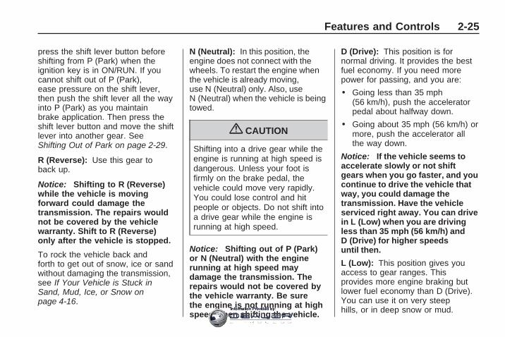
press the shift lever button beforeshifting from P (Park) when theignition key is in ON/RUN. If youcannot shift out of P (Park),ease pressure on the shift lever,then push the shift lever all the wayinto P (Park) as you maintainbrake application. Then press theshift lever button and move the shiftlever into another gear. SeeShifting Out of Park on page 2-29.
R (Reverse): Use this gear toback up.
Notice: Shifting to R (Reverse)while the vehicle is movingforward could damage thetransmission. The repairs wouldnot be covered by the vehiclewarranty. Shift to R (Reverse)only after the vehicle is stopped.
To rock the vehicle back andforth to get out of snow, ice or sandwithout damaging the transmission,see If Your Vehicle is Stuck inSand, Mud, Ice, or Snow onpage 4-16.
N (Neutral): In this position, theengine does not connect with thewheels. To restart the engine whenthe vehicle is already moving,use N (Neutral) only. Also, useN (Neutral) when the vehicle is beingtowed.
{ CAUTION
Shifting into a drive gear while theengine is running at high speed isdangerous. Unless your foot isfirmly on the brake pedal, thevehicle could move very rapidly.You could lose control and hitpeople or objects. Do not shift intoa drive gear while the engine isrunning at high speed.
Notice: Shifting out of P (Park)or N (Neutral) with the enginerunning at high speed maydamage the transmission. Therepairs would not be covered bythe vehicle warranty. Be surethe engine is not running at highspeed when shifting the vehicle.
D (Drive): This position is fornormal driving. It provides the bestfuel economy. If you need morepower for passing, and you are:
• Going less than 35 mph(56 km/h), push the acceleratorpedal about halfway down.
• Going about 35 mph (56 km/h) ormore, push the accelerator allthe way down.
Notice: If the vehicle seems toaccelerate slowly or not shiftgears when you go faster, and youcontinue to drive the vehicle thatway, you could damage thetransmission. Have the vehicleserviced right away. You can drivein L (Low) when you are drivingless than 35 mph (56 km/h) andD (Drive) for higher speedsuntil then.
L (Low): This position gives youaccess to gear ranges. Thisprovides more engine braking butlower fuel economy than D (Drive).You can use it on very steephills, or in deep snow or mud.
Features and Controls 2-25
Information Provided by:

Electronic RangeSelect (ERS) ModeERS mode allows you to choose thetop-gear limit of the transmissionand the vehicle’s speed whiledriving down hill or towing a trailer.The vehicle has an electronicshift position indicator within theinstrument panel cluster. Whenusing the ERS Mode a number willdisplay next to the L, indicatingthe current gear that has beenselected.
To use this feature:
1. Move the shift lever to L (Low).
2. Press the plus/minus buttonlocated on the shift lever, toincrease or decrease the gearrange available.
When you shift from D (Drive) toL (Low), the transmission will shift toa pre-determined lower gear range.The highest gear available forthis pre-determined range isdisplayed next to the L in the DIC.
See Driver Information Center (DIC)on page 3-44 and DIC Operationand Displays (With DIC Buttons) onpage 3-45 or DIC Operation andDisplays (Without DIC Buttons) onpage 3-51 for more information.The number displayed in theDIC is the highest gear that thetransmission will be allowedto operate in. This means that allgears below that number areavailable. For example, when4 (Fourth) is shown next to the L,1 (First) through 4 (Fourth) gearsare automatically shifted bythe vehicle. The transmission willnot shift into 5 (Fifth) until the+ (Plus) button is used or you shiftback into D (Drive).
While in L (Low), the transmissionwill prevent shifting to a lowergear range if the engine speed istoo high. You have a brief period oftime to slow the vehicle. If vehiclespeed is not reduced within the timeallowed, the lower gear range shiftwill not be completed. You must
further slow the vehicle, then pressthe − (Minus) button to thedesired lower gear range.
Automatic Engine Grade braking isnot available when the ERS is active.It is available in D (Drive) for bothnormal and Tow/Haul mode. Whileusing the ERS, cruise control and thetow/haul mode can be used. SeeTow/Haul Mode on page 2-26 formore information.
Tow/Haul Mode
_ (Tow/Haul): The vehicle mayhave a Tow/Haul mode.
The button is located on theinstrument panel under the climatecontrols.
Push the button to activate thesystem. Push it again to deactivatethe system. You can use thisfeature to assist when towing orhauling a heavy load.
2-26 Features and Controls
Information Provided by:

When Tow/Haul is activated theTow/Haul symbol will come on theinstrument panel cluster. See“Tow/Haul Mode” under Towing aTrailer on page 4-25 for moreinformation.
Automatic Engine GradeBrakingAutomatic Engine Grade Brakingassists when driving on a downhillgrade. It maintains vehicle speed byautomatically implementing a shiftschedule that uses the engine andthe transmission to slow the vehicle.The system will automaticallycommand downshifts to reducevehicle speed, until the brake pedalis no longer being pressed.
While in the Electronic RangeSelect (ERS) mode, grade brakingis deactivated, allowing thedriver to select a range and limitingthe highest gear available. Gradebraking is available for normaldriving and in Tow/Haul mode.See Automatic TransmissionOperation on page 2-24.
Parking Brake
To set the parking brake, hold theregular brake pedal down, then pushthe parking brake pedal down.
If the ignition is on, the brakesystem warning light will come on.See Brake System Warning Lighton page 3-36.
Notice: Driving with the parkingbrake on can overheat the brakesystem and cause premature wearor damage to brake system parts.Make sure that the parking brakeis fully released and the brakewarning light is off before driving.
To release the parking brake, holdthe regular brake pedal down,then push down momentarily on theparking brake pedal until you feelthe pedal release. Slowly pullyour foot up off the park brakepedal. If the parking brake isnot released when you begin todrive, the brake system warning lightwill be on and a chime will soundwarning you that the parkingbrake is still on.
If you are towing a trailer and areparking on a hill, see Towing aTrailer on page 4-25.
Features and Controls 2-27
Information Provided by:

Shifting Into Park
{ CAUTION
It can be dangerous to get out ofthe vehicle if the shift lever is notfully in P (Park) with the parkingbrake firmly set. The vehicle canroll. If you have left the enginerunning, the vehicle can movesuddenly. You or others could beinjured. To be sure the vehicle willnot move, even when you are onfairly level ground, use the stepsthat follow. If you are pulling atrailer, see Towing a Trailer onpage 4-25.
1. Hold the brake pedal down andset the parking brake. SeeParking Brake on page 2-27 formore information.
2. Move the shift lever into P (Park)by holding in the button on theshift lever and pushing theshift lever all the way towardthe front of the vehicle.
3. Turn the ignition key toLOCK/OFF.
4. Remove the key and take it withyou. If you can leave the vehiclewith the ignition key in yourhand, the vehicle is in P (Park).
Leaving the Vehicle with theEngine Running
{ CAUTION
It can be dangerous to leave thevehicle with the engine running.The vehicle could move suddenlyif the shift lever is not fully inP (Park) with the parking brakefirmly set. And, if you leave thevehicle with the engine running, itcould overheat and even catchfire. You or others could beinjured. Do not leave the vehiclewith the engine running.
If you have to leave the vehicle withthe engine running, be sure thevehicle is in P (Park) and the parkingbrake is firmly set before you leave it.After you have moved the shift leverinto P (Park), hold the regular brakepedal down. Then, see if you canmove the shift lever away fromP (Park) without first pushing thebutton.
If you can, it means that the shiftlever was not fully locked in P (Park).
Torque LockTorque lock is when the weight of thevehicle puts too much force on theparking pawl in the transmission.This happens when parking on a hilland shifting the transmission intoP (Park) is not done properly andthen it is difficult to shift out ofP (Park). To prevent torque lock, setthe parking brake and then shift intoP (Park). To find out how, see“Shifting Into Park” listed previously.
2-28 Features and Controls
Information Provided by:

If torque lock does occur, yourvehicle may need to be pusheduphill by another vehicle to relievethe parking pawl pressure, soyou can shift out of P (Park).
Shifting Out of ParkThe vehicle is equipped withan electronic shift lock releasesystem. The shift lock release isdesigned to:
• Prevent ignition key removalunless the shift lever is inP (Park) with the shift leverbutton fully released, and
• Prevent movement of the shiftlever out of P (Park), unlessthe ignition is in ON/RUNor ACC/ACCESSORY and theregular brake pedal is applied.
The shift lock release is alwaysfunctional except in the case of anuncharged or low voltage (less than9 volt) battery.
If the vehicle has an unchargedbattery or a battery with low voltage,try charging or jump starting thebattery. See Jump Starting onpage 5-29 for more information.
To shift out of P (Park):
1. Apply the brake pedal.
2. Press the shift lever button.
3. Move the shift lever to thedesired position.
If you still are unable to shift out ofP (Park):
1. Fully release the shift leverbutton.
2. While holding down the brakepedal, press the shift leverbutton again.
3. Move the shift lever to thedesired position.
If you still cannot move the shiftlever from P (Park), see yourdealer/retailer.
Parking Over ThingsThat Burn
{ CAUTION
Things that can burn could touchhot exhaust parts under thevehicle and ignite. Do not parkover papers, leaves, dry grass, orother things that can burn.
Features and Controls 2-29
Information Provided by:

Engine Exhaust
{ CAUTION
Engine exhaust contains CarbonMonoxide (CO) which cannot beseen or smelled. Exposure to COcan cause unconsciousness andeven death.
Exhaust may enter the vehicle if:• The vehicle idles in areas
with poor ventilation (parkinggarages, tunnels, deep snowthat may block underbodyairflow or tail pipes).
• The exhaust smells orsounds strange or different.
• The exhaust system leaksdue to corrosion or damage.
• The vehicle’s exhaust systemhas been modified, damagedor improperly repaired.
(Continued)
CAUTION (Continued)
• There are holes or openingsin the vehicle body fromdamage or after-marketmodifications that are notcompletely sealed.
If unusual fumes are detected or ifit is suspected that exhaust iscoming into the vehicle:
• Drive it only with the windowscompletely down.
• Have the vehicle repairedimmediately.
Never park the vehicle with theengine running in an enclosedarea such as a garage or abuilding that has no fresh airventilation.
Running the VehicleWhile ParkedIt is better not to park with theengine running. But if you ever haveto, here are some things to know.
{ CAUTION
Idling a vehicle in an enclosedarea with poor ventilation isdangerous. Engine exhaust mayenter the vehicle. Engine exhaustcontains Carbon Monoxide (CO)which cannot be seen or smelled.It can cause unconsciousnessand even death. Never run theengine in an enclosed area thathas no fresh air ventilation. Formore information, see EngineExhaust on page 2-30.
2-30 Features and Controls
Information Provided by:

{ CAUTION
It can be dangerous to get out ofthe vehicle if the automatictransmission shift lever is not fullyin P (Park) with the parking brakefirmly set. The vehicle can roll.Do not leave the vehicle when theengine is running unless you haveto. If you have left the enginerunning, the vehicle can movesuddenly. You or others could beinjured. To be sure the vehicle willnot move, even when you are onfairly level ground, always set theparking brake and move the shiftlever to P (Park).
Follow the proper steps to be surethe vehicle will not move. SeeShifting Into Park on page 2-28.
If parking on a hill and pullinga trailer, see Towing a Trailer onpage 4-25.
Mirrors
Manual Rearview MirrorAdjust the inside rearview mirrorto see clearly behind your vehicle.Hold the mirror in the center to moveit up or down and side to side.Use the day/night adjustment to helpprevent glare from the headlampsbehind you. Move the lever to theright for nighttime use and to the leftfor daytime use.
Vehicles with OnStar® havethree additional control buttonslocated at the bottom of the mirror.See your dealer/retailer for moreinformation about OnStar and how tosubscribe to it. See OnStar® Systemon page 2-43 for more information onthe services OnStar provides.
Automatic DimmingRearview MirrorThe vehicle may have an automaticdimming inside rearview mirror.
Vehicles with OnStar® havethree additional control buttons forthe OnStar® system. See yourdealer/retailer for more informationabout OnStar® and how to subscribeto it. See OnStar® System onpage 2-43 for more information aboutthe services OnStar® provides.
O (On/Off): Press to turn thedimming feature on or off.
The vehicle may also have a RearVision Camera (RVC). See RearVision Camera (RVC) on page 2-38for more information.
If the vehicle has RVC, the O buttonwill not be available.
Features and Controls 2-31
Information Provided by:

Automatic Dimming MirrorOperationAutomatic dimming reduces theglare from the headlamps ofthe vehicle behind you. The dimmingfeature comes on and the indicatorlight illuminates each time theignition is turned to start.
Cleaning the MirrorDo not spray glass cleaner directlyon the mirror. Use a soft toweldampened with water.
Outside Power Mirrors
Controls for the outside powermirrors are located on the driverdoor armrest.
To adjust each mirror:
1. Press (A) or (B) to select thedriver or passenger side mirror.
2. Press one of the four arrowslocated on the control pad toadjust the mirror.
3. Adjust each outside mirror sothat a little of the vehicle andthe area behind it can be seen.
4. Press either (A) or (B) again todeselect the mirror.
Manually fold the mirrors inwardto prevent damage when goingthrough an automatic car wash.To fold, push the mirror toward thevehicle. Push the mirror outward,to return it to the original position.
Using hood-mounted air deflectorsand add-on convex mirrorattachments could decrease mirrorperformance.
Turn Signal IndicatorThe vehicle may have a turn signalindicator lamp that is built intothe mirror housing. The turn signallamp flashes with the use of thevehicle’s turn signal and hazardflashers.
2-32 Features and Controls
Information Provided by:

Outside Power FoldawayMirrors
Vehicles with outside powerfoldaway mirrors, have the controlslocated on the driver door armrest.
Mirror Adjustment1. Press (C) to fold the mirrors out
to the driving position.
2. Press (D) to fold the mirrors in tothe folded position.
Resetting the Power FoldawayMirrorsReset the power foldaway mirrors if:
• The mirrors are accidentallyobstructed while folding.
• They are accidentally manuallyfolded/unfolded.
• The mirrors vibrate at normaldriving speeds.
Fold and unfold the mirrors one timeusing the mirror controls to resetthem to their normal position.A popping noise may be heardduring the resetting of the powerfoldaway mirrors. This soundis normal after a manual foldingoperation.
Turn Signal IndicatorThe vehicle may have a turn signalindicator lamp that is built intothe mirror housing. The turn signallamp flashes with the use of thevehicle’s turn signal and hazardflashers.
Features and Controls 2-33
Information Provided by:

Blind Spot MirrorsThe blind spot mirror is a smallconvex mirror built into the upper andouter corner of both outside mirrors.It is designed to increase drivervisibility and show objects that maybe in the vehicle’s blind zone.
Driving with the Blind SpotMirrorThe illustration represents how avehicle appears in the blindspot mirror when a vehicle isapproaching the blind zone.
1. When the approaching vehicle isa long distance away, the imagein the main mirror is smalland near the inboard edge ofthe mirror.
2. As the vehicle gets closer, theimage in the main mirror getslarger and moves outboard.
3. As the vehicle enters the blindzone, the image transitionsfrom the main mirror to the blindspot mirror.
4. When the vehicle is completelyin the blind zone, the image willonly appear in the blind spotmirror and is entirely off themain mirror.
2-34 Features and Controls
Information Provided by:

Using the Outside Mirror withthe Blind Spot Mirror1. Set the main mirror so that the
side of your vehicle can just beseen and your blind spotmirror has an unobstructed view.
2. When checking for traffic orbefore changing a lane, look atthe main driver/passenger sidemirror to observe traffic in theadjacent lane, behind yourvehicle. Check the blind spotmirror for a vehicle in the blindzone. Then, glance over yourshoulder to double checkbefore moving slowly into theadjacent lane.
Park Tilt MirrorsIf the vehicle has the memorypackage, the outside mirrors have apark tilt feature. This feature tilts theoutside mirrors to a preselectedposition when the vehicle is inR (Reverse). This allows the driver toview the curb for parallel parking.
The passenger and/or driver mirrorreturns to its original positionwhen the vehicle is shifted out ofR (Reverse), or the ignition is turnedoff or to OFF/LOCK.
This feature can be turned on or offthrough the Driver InformationCenter (DIC). See DIC VehicleCustomization (With DIC Buttons)on page 3-65 and Memory Seatand Mirrors on page 1-6 formore information.
Outside Convex Mirror
{ CAUTION
A convex mirror can make things(like other vehicles) look fartheraway than they really are. If youcut too sharply into the right lane,you could hit a vehicle on theright. Check the inside mirror orglance over your shoulder beforechanging lanes.
The passenger side mirror is convexshaped. A convex mirror’s surfaceis curved so more can be seen fromthe driver seat.
Outside Heated MirrorsFor vehicles with heated mirrors:
< (Rear Window Defogger):Press to heat the mirrors.
See “Rear Window Defogger” underDual Automatic Climate ControlSystem on page 3-22 for moreinformation.
Features and Controls 2-35
Information Provided by:

Object DetectionSystems
Ultrasonic Rear ParkingAssist (URPA)For vehicles with the UltrasonicRear Parking Assist (URPA) system,it operates at speeds less than5 mph (8 km/h), and assists thedriver with parking and avoidingobjects while in R (Reverse).The sensors on the rear bumper areused to detect the distance to anobject up to 8 feet (2.5 m) behindthe vehicle, and at least 10 inches(25.4 cm) off the ground.
{ CAUTION
The Ultrasonic Rear ParkingAssist (URPA) system does notreplace driver vision. It cannotdetect:
• objects that are below thebumper, underneath thevehicle, or if they are tooclose or far from the vehicle
• children, pedestrians,bicyclists, or pets.
If you do not use proper carebefore and while backing; vehicledamage, injury, or death couldoccur. Even with URPA, alwayscheck behind the vehicle beforebacking up. While backing, besure to look for objects and checkthe vehicle’s mirrors.
The display is located in theheadliner and can be seen bylooking over your right shoulder.
URPA uses three color-coded lightsto provide distance and systeminformation.
2-36 Features and Controls
Information Provided by:

How the System WorksURPA comes on automaticallywhen the shift lever is moved intoR (Reverse). The rear display brieflyilluminates to indicate the systemis working.
URPA operates only at speeds lessthan 5 mph (8 km/h). If the vehicleis above this speed, the red light onthe rear display flashes.
To be detected, objects must be atleast 10 inches (25.4 cm) off theground and below liftgate level.Objects must also be within 8 feet(2.5 m) from the rear bumper.This distance may be less duringwarmer or humid weather.
A single beep sounds the first timean object is detected. Beepingmay occur beginning at 23 inches(0.6 m). Beeping occurs for ashort time when the vehicle is closerthan 23 inches (0.6 m) and againat 1 foot (0.3 m) from the object.
The following describes how the URPA display lights appear as the vehiclegets closer to a detected object:
Description English Metricamber light 8 ft 2.5 m
amber/amber lights 40 in 1.0 mamber/amber/red lights 23 in 0.6 m
amber/amber/red lights flashing 1 ft 0.3 m
The system can be disabled throughthe Driver Information Center (DIC).See “Park Assist” under DICOperation and Displays (With DICButtons) on page 3-45 or DICOperation and Displays (WithoutDIC Buttons) on page 3-51for more information.
Features and Controls 2-37
Information Provided by:

When the System Does NotSeem to Work ProperlyIf the URPA system does notactivate due to a temporarycondition, the message PARKASSIST OFF displays on the DICand a red light will be shown on therear URPA display when the shiftlever is moved into R (Reverse).This may occur under the followingconditions:
• The driver disables the system.
• The ultrasonic sensors arenot clean. Keep the vehicle’s rearbumper free of mud, dirt, snow,ice and slush. For cleaninginstructions, see Washing YourVehicle on page 5-81.
• A trailer was attached to thevehicle, or a bicycle or an objectwas hanging out of the liftgateduring the last drive cycle, the redlight may illuminate in the reardisplay. Once the attached objectis removed, URPA will return tonormal operation.
• A tow bar is attached to thevehicle.
• The vehicle’s bumper isdamaged. Take the vehicle toyour dealer/retailer to repair thesystem.
• Other conditions may affectsystem performance, such asvibrations from a jackhammer orthe compression of air brakes ona very large truck.
If the system is still disabled, afterdriving forward at least 15 mph(25 km/h), take the vehicle to yourdealer/retailer.
Rear VisionCamera (RVC)The vehicle may have a Rear VisionCamera system. Read this entiresection before using it.
{ CAUTION
The Rear Vision Camera (RVC)system does not replace drivervision. RVC does not:
• Detect objects that areoutside the camera’s field ofview, below the bumper, orunderneath the vehicle.
• Detect children, pedestrians,bicyclists, or pets.
Do not back the vehicle by onlylooking at the rear vision camerascreen, or use the screen duringlonger, higher speed backingmaneuvers or where there couldbe cross-traffic. Your judgeddistances using the screen willdiffer from actual distances.
(Continued)
2-38 Features and Controls
Information Provided by:

CAUTION (Continued)
So if you do not use proper carebefore backing up, you could hit avehicle, child, pedestrian, bicyclist,or pet, resulting in vehicledamage, injury, or death. Eventhough the vehicle has the RVCsystem, always check carefullybefore backing up by checkingbehind and around the vehicle.
Vehicles Without NavigationSystemThe rear vision camera system isdesigned to help the driverwhen backing up by displaying aview of the area behind the vehicle.When the key is in the ON/RUNposition and the driver shiftsthe vehicle into R (Reverse), thevideo image automatically appearson the inside rear view mirror.
Once the driver shifts out ofR (Reverse), the video imageautomatically disappears from theinside rear view mirror.
Turning the Rear Vision CameraSystem Off or On
To turn off the rear vision camerasystem, press and hold z, locatedon the inside rearview mirror,until the left indicator light turns off.The rear vision camera displayis now disabled.
To turn the rear vision camerasystem on again, press andhold z until the left indicator lightilluminates. The rear visioncamera system display is nowenabled and the display will appearin the mirror normally.
Vehicles With NavigationSystemThe rear vision camera system isdesigned to help the driver whenbacking up by displaying a viewof the area behind the vehicle.When the driver shifts the vehicleinto R (Reverse), the video imageautomatically appears on thenavigation screen. Once the drivershifts out of R (Reverse), thenavigation screen will go back to thelast screen that had been displayed,after a delay.
Turning the Rear Vision CameraSystem On or Off
To turn the rear vision camerasystem on or off:
1. Shift into P (Park).
2. Press the MENU button to enterthe configure menu options, thenpress the MENU hard key toselect Display or touch theDisplay screen button.
Features and Controls 2-39
Information Provided by:
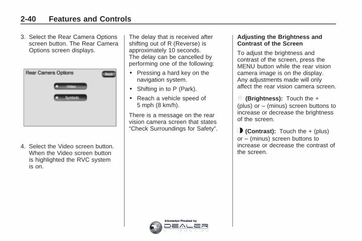
3. Select the Rear Camera Optionsscreen button. The Rear CameraOptions screen displays.
4. Select the Video screen button.When the Video screen buttonis highlighted the RVC systemis on.
The delay that is received aftershifting out of R (Reverse) isapproximately 10 seconds.The delay can be cancelled byperforming one of the following:
• Pressing a hard key on thenavigation system.
• Shifting in to P (Park).
• Reach a vehicle speed of5 mph (8 km/h).
There is a message on the rearvision camera screen that states“Check Surroundings for Safety”.
Adjusting the Brightness andContrast of the Screen
To adjust the brightness andcontrast of the screen, press theMENU button while the rear visioncamera image is on the display.Any adjustments made will onlyaffect the rear vision camera screen.
] (Brightness): Touch the +(plus) or – (minus) screen buttons toincrease or decrease the brightnessof the screen.
_ (Contrast): Touch the + (plus)or – (minus) screen buttons toincrease or decrease the contrast ofthe screen.
2-40 Features and Controls
Information Provided by:

Symbols
The navigation system may have afeature that lets the driver viewsymbols on the navigation screenwhile using the rear vision camera.The Ultrasonic Rear Park Assist(URPA) system must not be disabledto use the caution symbols. If URPAhas been disabled and the symbolshave been turned on, the RearParking Assist Symbols Unavailableerror message may display. SeeUltrasonic Rear Parking Assist(URPA) on page 2-36.
The symbols appear when an objecthas been detected by the URPAsystem. The symbol may cover theobject when viewing the navigationscreen.
To turn the symbols on or off:
1. Make sure that URPA has notbeen disabled.
2. Shift into P (Park).
3. Press the MENU hard key toenter the configure menuoptions, then press the MENUhard key repeatedly until Displayis selected or touch the Displayscreen button.
4. Select the Rear Camera Optionsscreen button. The Rear CameraOptions screen will display.
5. Touch the Symbols screenbutton. The screen button will behighlighted when on.
Rear Vision Camera ErrorMessages
Service Rear Vision CameraSystem: This message can displaywhen the system is not receivinginformation it requires from othervehicle systems.If any other problem occurs or if aproblem persists, see yourdealer/retailer.
Rear Vision Camera Location
The camera is located above thelicense plate.
Features and Controls 2-41
Information Provided by:

The area displayed by the camerais limited and does not displayobjects that are close to eithercorner or under the bumper. Thearea displayed can vary dependingon vehicle orientation or roadconditions. The distance of theimage that appears on the screendiffers from the actual distance.
The following illustration shows thefield of view that the cameraprovides.
A. View displayed by the camera.B. Corner of the rear bumper.
When the System Does NotSeem To Work ProperlyThe rear vision camera systemmight not work properly or display aclear image if:
• The RVC is turned off. See“Turning the Rear CameraSystem On or Off” earlier in thissection.
• It is dark.
• The sun or the beam of headlightsis shining directly into thecamera lens.
• Ice, snow, mud, or anything elsebuilds up on the camera lens.Clean the lens, rinse it with water,and wipe it with a soft cloth.
2-42 Features and Controls
Information Provided by:

• The back of the vehicle is in anaccident, the position andmounting angle of the camera canchange or the camera can beaffected. Be sure to have thecamera and its position andmounting angle checked at yourdealer/retailer.
• There are extreme temperaturechanges.
The rear vision camera systemdisplay in the rearview mirror mayturn off or not appear as expecteddue to one of the followingconditions. If this occurs the leftindicator light on the mirror will flash.
• A slow flash may indicate aloss of video signal, or novideo signal present during thereverse cycle.
• A fast flash may indicate that thedisplay has been on for themaximum allowable time during areverse cycle, or the display hasreached an Over Temperaturelimit.The fast flash conditions are usedto protect the video device fromhigh temperature conditions.Once conditions return to normalthe device will reset and thegreen indicator will stop flashing.
During any of these fault conditions,the display will be blank and theindicator will continue to flash as longas the vehicle is in R (Reverse) oruntil the conditions return to normal.
Pressing and holding z when theleft indicator light is flashing will turnoff the video display along withthe left indicator light.
OnStar® System
OnStar uses several innovativetechnologies and live advisors toprovide a wide range of safety,security, information, andconvenience services. If the airbagsdeploy, the system is designed tomake an automatic call to OnStarEmergency advisors who canrequest emergency services be sentto your location. If the keys arelocked in the vehicle, call OnStar at1-888-4-ONSTAR to have a signalsent to unlock the doors. OnStarHands-Free Calling, including30 trial minutes good for 60 days, isavailable on most vehicles. OnStarTurn-by-Turn Navigation service,with one trial route, is available onmost vehicles. Press the OnStarbutton to have an OnStar advisorcontact Roadside Service.
Features and Controls 2-43
Information Provided by:

OnStar service is provided subjectto the OnStar Terms and Conditionsincluded in the OnStar Subscriberglove box literature.
Some services such as RemoteDoor Unlock or Stolen VehicleLocation Assistance may not beavailable until the owner of thevehicle registers with OnStar.After the first prepaid year, contactOnStar to select a monthly orannual subscription payment plan.If a payment plan is not selected,the OnStar system and all services,including airbag notification andemergency services, may bedeactivated and no longer available.For more information visitonstar.com (U.S.) or onstar.ca(Canada), or press the OnStarbutton to speak with an advisor.
Not all OnStar services are availableon all vehicles. To check if thisvehicle is able to provide the servicesdescribed below, or for a fulldescription of OnStar services andsystem limitations, see the OnStarOwner’s Guide in the glove box orvisit onstar.com (U.S.) or onstar.ca(Canada), contact OnStar at1-888-4-ONSTAR (1-888-466-7827)or TTY 1-877-248-2080, or press theOnStar button to speak with anOnStar advisor 24 hours a day,7 days a week.
OnStar Services Availablewith the Safe & Sound Plan• Automatic Notification of
Airbag Deployment
• Advanced Automatic CrashNotification (AACN) (If equipped)
• Link to Emergency Services
• Roadside Assistance
• Stolen Vehicle LocationAssistance
• Remote Door Unlock/VehicleAlert
• OnStar Vehicle Diagnostic Email
• GM Goodwrench On DemandDiagnostics
• OnStar Hands-Free Calling with30 trial minutes
• OnStar Virtual Advisor(U.S. Only)
OnStar Services Included withDirections & Connections Plan• All Safe and Sound Plan Services
• OnStar Turn-by-Turn Navigation(If equipped) or DrivingDirections - Advisor delivered
• RideAssist
• Information and ConvenienceServices
2-44 Features and Controls
Information Provided by:

OnStar Hands-Free CallingOnStar Hands-Free Calling allowseligible OnStar subscribers to makeand receive calls using voicecommands. Hands-Free Calling isfully integrated into the vehicle, andcan be used with OnStar Pre-PaidMinute Packages. Most vehiclesinclude 30 trial minutes good for60 days. Hands-Free Calling canalso be linked to a Verizon Wirelessservice plan in the U.S. or a BellMobility service plan in Canada,depending on eligibility. To find outmore, refer to the OnStar Owner’sGuide in the vehicle’s glove box, visitonstar.com or onstar.ca, or speakwith an OnStar advisor by pressingthe OnStar button or calling1-888-4-ONSTAR (1-888-466-7827).
OnStar Turn-by-TurnNavigationVehicles with the OnStarTurn-by-Turn Navigation systemcan provide voice-guided drivingdirections. Press the OnStar buttonto have an OnStar advisor locate abusiness or address and downloaddriving directions to the vehicle.Voice-guided directions to thedesired destination will play throughthe audio system speakers. See theOnStar Owner’s Guide for moreinformation.
OnStar Virtual AdvisorOnStar Virtual Advisor is a feature ofOnStar Hands-Free Calling that usesminutes to access location-basedweather, local traffic reports, andstock quotes. Press the phone buttonand give a few simple voicecommands to browse through thevarious topics. See the OnStarOwner’s Guide for more information.This feature is only available in thecontinental U.S.
OnStar Steering WheelControlsThis vehicle may have a Talk/Mutebutton that can be used to interactwith OnStar Hands-Free Calling.See Audio Steering Wheel Controlson page 3-125 for more information.
On some vehicles, the mute buttoncan be used to dial numbersinto voice mail systems, or to dialphone extensions. See theOnStar Owner’s Guide for moreinformation.
Features and Controls 2-45
Information Provided by:

How OnStar Service WorksThe OnStar system can record andtransmit vehicle information. Thisinformation is automatically sent toan OnStar Call Center when theOnStar button is pressed, theemergency button is pressed, or ifthe airbags or AACN system deploy.This information usually includesthe vehicle’s GPS location and, inthe event of a crash, additionalinformation regarding the crash thatthe vehicle was involved in (e.g.the direction from which the vehiclewas hit). When the Virtual Advisorfeature of OnStar Hands-FreeCalling is used, the vehicle alsosends OnStar the vehicle’sGPS location so they can provideservices where it is located.
OnStar service cannot work unlessthe vehicle is in a place whereOnStar has an agreement with awireless service provider for servicein that area. OnStar service alsocannot work unless the vehicle is in aplace where the wireless service
provider OnStar has hired for thatarea has coverage, network capacityand reception when the service isneeded, and technology that iscompatible with the OnStar service.Not all services are availableeverywhere, particularly in remote orenclosed areas, or at all times.
Location information about thevehicle is only available if the GPSsatellite signals are unobstructedand available.
The vehicle must have a workingelectrical system, including adequatebattery power, for the OnStarequipment to operate. There areother problems OnStar cannotcontrol that may prevent OnStarfrom providing OnStar service atany particular time or place.Some examples are damage toimportant parts of the vehicle in acrash, hills, tall buildings, tunnels,weather or wireless phone networkcongestion.
Your Responsibility
Increase the volume of the radio ifthe OnStar advisor cannot be heard.If the light next to the OnStarbuttons is red, the system may notbe functioning properly. Pressthe OnStar button and request avehicle diagnostic. If the lightappears clear (no light is appearing),your OnStar subscription hasexpired and all services have beendeactivated. Press the OnStarbutton to confirm that the OnStarequipment is active.
2-46 Features and Controls
Information Provided by:

Universal HomeRemote SystemThe Universal Home RemoteSystem provides a way toreplace up to three hand-heldRadio-Frequency (RF) transmittersused to activate devices suchas garage door openers, securitysystems, and home lighting.
This device complies with Part 15 ofthe FCC Rules. Operation is subjectto the following two conditions:
1. This device may not causeharmful interference.
2. This device must accept anyinterference received, includinginterference that may causeundesired operation.
This device complies with RSS-210of Industry Canada. Operation issubject to the following twoconditions:
1. This device may not causeinterference.
2. This device must accept anyinterference received, includinginterference that may causeundesired operation of thedevice.
Changes or modifications to thissystem by other than an authorizedservice facility could voidauthorization to use this equipment.
Universal Home RemoteSystem Operation
If there is one triangular LightEmitting Diode (LED) indicatorlight above the Universal HomeRemote buttons, follow theinstructions below.
This system provides a way toreplace up to three remote controltransmitters used to activate devicessuch as garage door openers,security systems, and homeautomation devices.
Features and Controls 2-47
Information Provided by:

Do not use the Universal HomeRemote with any garage dooropener that does not have the stopand reverse feature. This includesany garage door opener modelmanufactured before April 1, 1982.
Read the instructions completelybefore attempting to programthe Universal Home Remote.Because of the steps involved, itmay be helpful to have anotherperson available to assist you in theprogramming the Universal HomeRemote.
Keep the original hand-heldtransmitter for use in other vehiclesas well as for future UniversalHome Remote programming. It isalso recommended that uponthe sale of the vehicle, theprogrammed Universal HomeRemote buttons should be erasedfor security purposes. See “ErasingUniversal Home Remote Buttons”later in this section.
When programming a garage door,park outside of the garage. Parkdirectly in line with and facingthe garage door opener motor-heador gate motor-head. Be sure thatpeople and objects are clear of thegarage door or gate that is beingprogrammed.
It is recommended that a newbattery be installed in yourhand-held transmitter for quickerand more accurate transmission ofthe radio-frequency signal.
Programming the UniversalHome Remote SystemFor questions or help programmingthe Universal Home RemoteSystem, call 1-800-355-3515 orgo to www.homelink.com.
Programming a garage door openerinvolves time-sensitive actions,so read the entire procedure beforestarting. Otherwise, the devicewill time out and the procedure willhave to be repeated.
To program up to three devices:
1. From inside the vehicle, pressand hold down the two outsidebuttons at the same time,releasing only when the UniversalHome Remote indicator lightbegins to flash, after 20 seconds.This step will erase the factorysettings or all previouslyprogrammed buttons.Do not hold down the buttons forlonger than 30 seconds anddo not repeat this step toprogram the remaining twoUniversal Home Remote buttons.
2-48 Features and Controls
Information Provided by:

2. Hold the end of your hand-heldtransmitter about 1 to 3 inches(3 to 8 cm) away from theUniversal Home Remote buttonswhile keeping the indicator light inview. The hand-held transmitterwas supplied by the manufacturerof your garage door openerreceiver (motor head unit).
3. At the same time, press and holdboth the Universal Home Remotebutton to be used to control thegarage door and the hand-heldtransmitter button. Do not releasethe Universal Home Remotebutton or the hand-heldtransmitter button until Step 4has been completed.Some entry gates and garagedoor openers may requiresubstitution of Step 3 with theprocedure noted in “GateOperator and CanadianProgramming” later in thissection.
4. The indicator light on theUniversal Home Remotewill flash slowly at first and thenrapidly after Universal HomeRemote successfully receivesthe frequency signal fromthe hand-held transmitter.Release both buttons.
5. Press and hold the newly-trainedUniversal Home Remote buttonand observe the indicator light.If the indicator light stays oncontinuously, the programming iscomplete and the garage doorshould move when the UniversalHome Remote button is pressedand released. There is no need tocontinue programming Steps 6through 8.If the Universal Home Remoteindicator light blinks rapidlyfor two seconds and then turnsto a constant light, continuewith the programming Steps 6through 8.
It may be helpful to have anotherperson assist with the remainingsteps.
6. After Steps 1 through 5 havebeen completed, locate insidethe garage the garage dooropener receiver (motor-headunit). Locate the “Learn” or“Smart” button. The name andcolor of the button may varyby manufacturer.
Features and Controls 2-49
Information Provided by:

7. Firmly press and release the“Learn” or “Smart” button.After you press this button,you will have 30 seconds tocomplete Step 8.
8. Immediately return to the vehicle.Firmly press and hold theUniversal Home Remote button,chosen in Step 3 to controlthe garage door, for two seconds,and then release it. If thegarage door does not move,press and hold the same buttona second time for two seconds,and then release it. Again, ifthe door does not move, pressand hold the same button athird time for two seconds, andthen release.The Universal Home Remoteshould now activate thegarage door.
To program the remaining twoUniversal Home Remote buttons,begin with Step 2 of “Programmingthe Universal Home RemoteSystem.” Do not repeat Step 1,as this will erase all previousprogramming from the UniversalHome Remote buttons.
Gate Operator and CanadianProgrammingIf you have questions or need helpprogramming the UniversalHome Remote System, call1-800-355-3515 or go towww.homelink.com.
Canadian radio-frequency lawsrequire transmitter signals to timeout or quit after several seconds oftransmission. This may not belong enough for Universal Home
Remote to pick up the signal duringprogramming. Similarly, someU.S. gate operators aremanufactured to time out in thesame manner.
If you live in Canada, or you arehaving difficulty programming a gateoperator or garage door openerby using the “ProgrammingUniversal Home Remote”procedures, regardless of whereyou live, replace Step 3 under“Programming Universal HomeRemote” with the following:
Continue to press and hold theUniversal Home Remote buttonwhile you press and release everytwo seconds (cycle) the hand-heldtransmitter button until the frequencysignal has been successfully
2-50 Features and Controls
Information Provided by:

accepted by the Universal HomeRemote. The Universal HomeRemote indicator light will flashslowly at first and then rapidly.Proceed with Step 4 under“Programming Universal HomeRemote” to complete.
Using Universal Home RemotePress and hold the appropriateUniversal Home Remote button for atleast half of a second. The indicatorlight will come on while the signal isbeing transmitted.
Erasing Universal HomeRemote ButtonsThe programmed buttons should beerased when the vehicle is soldor the lease ends.
To erase all programmed buttons onthe Universal Home Remote device:
1. Press and hold down thetwo outside buttons untilthe indicator light begins to flash,after 20 seconds.
2. Release both buttons.
Reprogramming a SingleUniversal Home RemoteButtonTo reprogram any of the threeUniversal Home Remote buttons,repeat the programming instructionsearlier in this section, beginningwith Step 2.
For help or information on theUniversal Home Remote System,call the customer assistance phonenumber under Customer AssistanceOffices on page 7-5.
Features and Controls 2-51
Information Provided by:
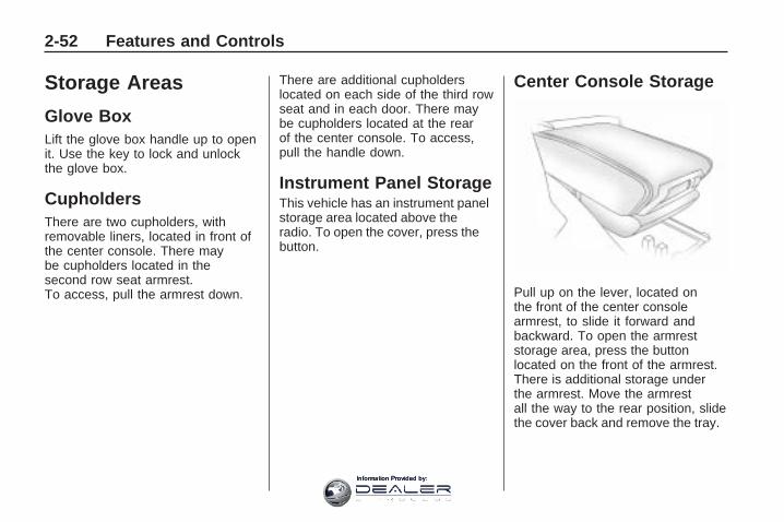
Storage Areas
Glove BoxLift the glove box handle up to openit. Use the key to lock and unlockthe glove box.
CupholdersThere are two cupholders, withremovable liners, located in front ofthe center console. There maybe cupholders located in thesecond row seat armrest.To access, pull the armrest down.
There are additional cupholderslocated on each side of the third rowseat and in each door. There maybe cupholders located at the rearof the center console. To access,pull the handle down.
Instrument Panel StorageThis vehicle has an instrument panelstorage area located above theradio. To open the cover, press thebutton.
Center Console Storage
Pull up on the lever, located onthe front of the center consolearmrest, to slide it forward andbackward. To open the armreststorage area, press the buttonlocated on the front of the armrest.There is additional storage underthe armrest. Move the armrestall the way to the rear position, slidethe cover back and remove the tray.
2-52 Features and Controls
Information Provided by:

Second Row CenterConsole
For vehicles with a second rowcenter console, open each area toaccess the storage compartmentinside.
To access the upper storage area,press the upper button (B) andlift up. To access the lower storagearea, press the lower button (C)and lift up. The top of the consolecan be folded forward for increasedstorage area. Lift up on handleon the rear of the console (A) andpull forward.
{ CAUTION
Never open more than one of thethree latches at a time to helpavoid personal injury and damageto the console.
Notice: Slide the front consoleas far forward as it will go beforefolding the second row consoleforward to help prevent damageto the consoles.
Features and Controls 2-53
Information Provided by:

Floor MatsIf the floor mat has a snap retainer,a grommet in the driver sidefloor mat attaches to a hook on thefloor of the vehicle to secure thefloor mat. To remove the floor mat,pull the mat towards the rear ofthe vehicle until the grommet can beremoved from the hook.
If the floor mat has a knob retainer,a grommet in the floor matattaches to a knob on the floor ofthe vehicle to secure the floormat. To remove the floor mat, turnthe knob till it is aligned with theslot in the floor mat grommetand pull the floor mat up.To reinstall, center the slot in thefloor mat grommet with the knob onthe floor and set the mat in place.Then turn the knob until it isperpendicular to the slot in thegrommet to lock the mat in place.
Luggage Carrier
{ CAUTION
If something is carried ontop of the vehicle that is longeror wider than the luggagecarrier — like paneling, plywood,or a mattress — the wind cancatch it while the vehicle is beingdriven. This can cause a driver tolose control. The item beingcarried could be violently torn off,and this could cause a collision,and damage the vehicle. Itemsmay be carried inside. Nevercarry something longer or widerthan the luggage carrier on top ofthe vehicle.
The luggage carrier allows theloading of things on top ofthe vehicle. Crossrails are availableat your dealer/retailer.
Notice: Loading cargo on theluggage carrier that weighs morethan 200 lbs (91 kg) or hangsover the rear or sides of thevehicle can damage the vehicle.Load cargo so that it rests asfar forward as possible andagainst the side rails, makingsure to fasten it securely.
Do not exceed the maximum vehiclecapacity when loading the vehicle.For more information on vehiclecapacity and loading, see Loadingthe Vehicle on page 4-16.
To prevent damage or loss of cargowhile driving, check to make surethe cargo is still securely fastened.
2-54 Features and Controls
Information Provided by:

Convenience NetUse the convenience net, located inthe rear, to store small loads asfar forward as possible. Thenet should not be used to storeheavy loads.
Cargo CoverFor vehicles with a cargo cover,it can be used to cover items in therear of the vehicle. To install thecover, place the loops on eachcorner of the cover on the four hooksin the rear of the vehicle. The covershould be stored securely whennot in use.
Cargo Tie DownsFour cargo tie-downs are located inthe rear compartment of the vehicle.The tie-downs can be used to securesmall loads.
Cargo ManagementSystemThis vehicle has a cargomanagement system locatedin the rear of the vehicle.
To remove the cargo managementcover:
1. Open the cover. It remains openwhen lifted.
2. Pull the cover up making sure tounhook the hinges at the rear ofthe cover.
{ CAUTION
An improperly latched and closedcargo cover, or cargo cover leftin the open position, could bethrown about the vehicle during acollision or sudden maneuver.Someone could be injured.Be sure to return the cover to theclosed position and latch beforedriving. If the cover is removed,always store it outside of thevehicle. When it is replaced,always be sure that it is securelyreattached.
3. Remove the cover from thevehicle and store outside ofthe vehicle.
Features and Controls 2-55
Information Provided by:
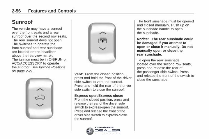
SunroofThe vehicle may have a sunroofover the front seats and a rearsunroof over the second row seats.The rear sunroof does not open.The switches to operate thefront sunroof and rear sunshadeare located on the headlinerabove the rearview mirror.The ignition must be in ON/RUN orACC/ACCESSORY to operatethe sunroof. See Ignition Positionson page 2-21.
Vent: From the closed position,press and hold the front of the driverside switch to vent the sunroof.Press and hold the rear of the driverside switch to close the sunroof.
Express-open/Express-close:From the closed position, press andrelease the rear of the driver sideswitch to express-open the sunroof.Press and release the front of thedriver side switch to express-closethe sunroof.
The front sunshade must be openedand closed manually. Push up onthe sunshade handle to openthe sunshade.
Notice: The rear sunshade couldbe damaged if you attempt toopen or close it manually. Do notmanually open or close therear sunshade.
To open the rear sunshade,located over the second row seats,press and release the rear ofthe passenger side switch. Pressand release the front of the switch toclose the sunshade.
2-56 Features and Controls
Information Provided by:

Instrument Panel
Instrument Panel OverviewInstrument Panel Overview .....3-4Hazard Warning Flashers .......3-5Horn ....................................3-5Tilt and Telescopic SteeringWheel ................................3-6
Turn Signal/MultifunctionLever .................................3-6
Turn and Lane-ChangeSignals ...............................3-6
Headlamp High/Low-BeamChanger .............................3-7
Flash-to-Pass ........................3-7Windshield Wipers .................3-7Windshield Washer ................3-8Rear Window Wiper/Washer ...3-9Cruise Control ......................3-9Exterior Lamps ....................3-11Delayed Headlamps .............3-12Daytime RunningLamps (DRL)/AutomaticHeadlamp System ..............3-12
Fog Lamps .........................3-13Instrument PanelBrightness .........................3-13
Courtesy Lamps ..................3-14Dome Lamps ......................3-14Dome Lamp Override ...........3-14Entry Lighting ......................3-14Delayed Entry Lighting .........3-15Delayed Exit Lighting ...........3-15Parade Dimming ..................3-15Reading Lamps ...................3-15Electric PowerManagement .....................3-15
Battery Run-DownProtection .........................3-16
Accessory Power Outlet(s) ....3-17Power Outlet 115 VoltAlternating Current .............3-18
Climate ControlsClimate Control System ........3-19Dual Automatic ClimateControl System ..................3-22
Outlet Adjustment ................3-27Rear Air Conditioning andHeating System .................3-28
Rear Air Conditioning andHeating System andElectronic ClimateControls ............................3-29
Warning Lights, Gages, andIndicatorsWarning Lights, Gages, andIndicators ..........................3-30
Instrument Panel Cluster .......3-31Speedometer andOdometer .........................3-32
Tachometer ........................3-32Safety Belt Reminders ..........3-32Airbag Readiness Light .........3-33Passenger Airbag StatusIndicator ...........................3-33
Charging System Light .........3-34Voltmeter Gage ...................3-35Brake System WarningLight ................................3-36
Antilock Brake System(ABS) Warning Light ...........3-37
StabiliTrak® Indicator Light ....3-37Engine Coolant TemperatureWarning Light ....................3-38
Engine CoolantTemperature Gage .............3-38
Tire Pressure Light ..............3-39MalfunctionIndicator Lamp ..................3-39
Oil Pressure Light ................3-42Security Light ......................3-43
Instrument Panel 3-1
Information Provided by:

Cruise Control Light .............3-43Highbeam On Light ..............3-43Tow/Haul Mode Light ...........3-43Fuel Gage ..........................3-43
Driver InformationCenter (DIC)Driver InformationCenter (DIC) .....................3-44
DIC Operation and Displays(With DIC Buttons) .............3-45
DIC Operation and Displays(Without DIC Buttons) .........3-51
DIC Compass .....................3-54DIC Warnings andMessages .........................3-56
DIC Vehicle Customization(With DIC Buttons) .............3-65
Audio System(s)Audio System(s) ..................3-73Setting the Clock .................3-74Radio(s) .............................3-75Using an MP3(Radio with CD) .................3-92
Using an MP3 (Radio withCD and DVD Player) ..........3-96
XM Radio Messages ..........3-102
Navigation/Radio System .....3-103Bluetooth® ........................3-103Rear Seat Entertainment(RSE) System ..................3-114
Rear Seat Audio (RSA) ......3-123Theft-Deterrent Feature .......3-125Audio Steering WheelControls ..........................3-125
Radio Reception ................3-126Multi-Band Antenna ............3-127
3-2 Instrument Panel
Information Provided by:

✍ NOTES
Instrument Panel 3-3
Information Provided by:

Instrument Panel Overview
3-4 Instrument Panel
Information Provided by:

The main components of theinstrument panel are listed here:A. Turn Signal/Multifunction
Lever on page 3-6. WindshieldWipers on page 3-7.
B. Instrument Panel Cluster onpage 3-31.
C. Audio Steering Wheel Controlson page 3-125.
D. Instrument Panel Storage onpage 2-52.
E. Audio System(s) on page 3-73or Navigation/Radio System onpage 3-103 (If Equipped).
F. Outlet Adjustment on page 3-27.G. Exterior Lamps on page 3-11.
Fog Lamps on page 3-13(If Equipped).
H. Dome Lamp Override onpage 3-14. Instrument PanelBrightness on page 3-13. HeatedWindshield Washer Button. SeeWindshield Washer on page 3-8.
I. Cruise Control on page 3-9.J. Tilt and Telescopic Steering
Wheel on page 3-6.
K. Horn on page 3-5.L. Driver Information Center (DIC)
on page 3-44.M. Climate Control System on
page 3-19 or Dual AutomaticClimate Control System onpage 3-22.
N. Shift Lever. See Shifting IntoPark on page 2-28.
O. Accessory Power Outlet(s) onpage 3-17.
P. Rear Window Wiper/Washeron page 3-9. Traction ControlSystem (TCS) Disable Button.See StabiliTrak® System onpage 4-5. Tow/Haul Modeon page 2-26 (If Equipped).Power Liftgate on page 2-11(If Equipped).
Q. Heated Seats on page 1-5.R. Hazard Warning Flashers on
page 3-5.S. Passenger Air Bag Status
Indicator.T. Glove Box on page 2-52.
Hazard Warning Flashers
| Hazard Warning Flasher: Pressthis button located on the instrumentpanel below the audio system, tomake the front and rear turn signallamps flash on and off. This warnsothers that you are having trouble.Press again to turn the flashers off.
The turn signals do not work whilethe hazard warning flashers are on.
HornPress near or on the horn symbolson the steering wheel pad to soundthe horn.
Instrument Panel 3-5
Information Provided by:

Tilt and TelescopicSteering WheelThe steering wheel can be adjusted.
The adjustment lever is located onthe left side of the steering column.
Pull the lever down to move thesteering wheel up or down and inor out. Pull the lever up to lockthe steering wheel in place.
Do not adjust the steering wheelwhile driving.
Turn Signal/MultifunctionLever
The lever on the left side of thesteering column includes thefollowing:
G : Turn and Lane-ChangeSignals
3 : Headlamp High/Low-BeamChanger
N : Windshield Wipers
L : Windshield Washer
Flash-to-Pass Feature.Information for these features is onthe pages following.For information on the headlamps,see Exterior Lamps on page 3-11.
Turn and Lane-ChangeSignals
An arrow on the instrument panelcluster flashes in the direction of theturn or lane change.Move the lever all the way up ordown to signal a turn.Raise or lower the lever until thearrow starts to flash to signal a lanechange. Hold it there until the lanechange is completed. If the lever isbriefly pressed and released, the turnsignal flashes three times.The lever returns to its startingposition whenever it is released.If after signaling a turn or lanechange the arrow flashes rapidly ordoes not come on, a signal bulbmight be burned out.Have the bulbs replaced. If the bulbis not burned out, check the fuse.See Fuses and Circuit Breakers onpage 5-86.
3-6 Instrument Panel
Information Provided by:
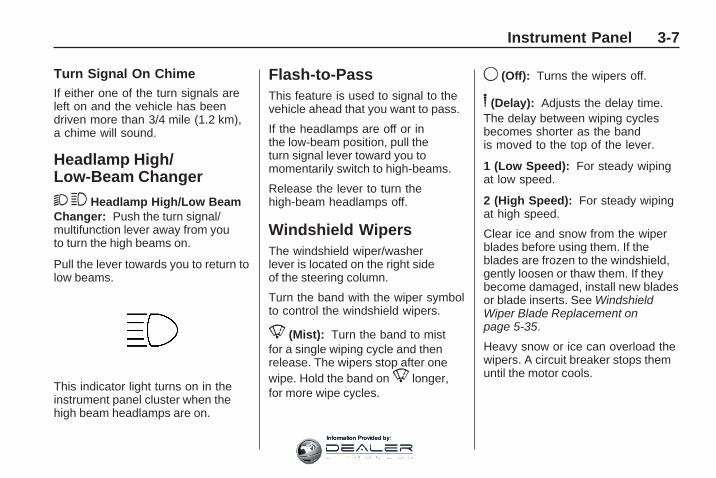
Turn Signal On ChimeIf either one of the turn signals areleft on and the vehicle has beendriven more than 3/4 mile (1.2 km),a chime will sound.
Headlamp High/Low-Beam Changer
23 Headlamp High/Low BeamChanger: Push the turn signal/multifunction lever away from youto turn the high beams on.
Pull the lever towards you to return tolow beams.
This indicator light turns on in theinstrument panel cluster when thehigh beam headlamps are on.
Flash-to-PassThis feature is used to signal to thevehicle ahead that you want to pass.
If the headlamps are off or inthe low-beam position, pull theturn signal lever toward you tomomentarily switch to high-beams.
Release the lever to turn thehigh-beam headlamps off.
Windshield WipersThe windshield wiper/washerlever is located on the right sideof the steering column.
Turn the band with the wiper symbolto control the windshield wipers.
8 (Mist): Turn the band to mistfor a single wiping cycle and thenrelease. The wipers stop after onewipe. Hold the band on 8 longer,for more wipe cycles.
9 (Off): Turns the wipers off.
6 (Delay): Adjusts the delay time.The delay between wiping cyclesbecomes shorter as the bandis moved to the top of the lever.
1 (Low Speed): For steady wipingat low speed.
2 (High Speed): For steady wipingat high speed.
Clear ice and snow from the wiperblades before using them. If theblades are frozen to the windshield,gently loosen or thaw them. If theybecome damaged, install new bladesor blade inserts. See WindshieldWiper Blade Replacement onpage 5-35.
Heavy snow or ice can overload thewipers. A circuit breaker stops themuntil the motor cools.
Instrument Panel 3-7
Information Provided by:

Windshield Washer
J (Washer Fluid): Press thebutton located at the end of theturn signal/multifunction lever, tospray washer fluid on the windshield.The wipers clear the windshield andeither stop or return to the presetspeed. The ignition key must be inACC/ACCESSORY or ON/RUN forthis to work. See Windshield WasherFluid on page 5-24 WindshieldWasher Fluid.
{ CAUTION
In freezing weather, do not useyour washer until the windshieldis warmed. Otherwise thewasher fluid can form ice on thewindshield, blocking your vision.
WASHER FLUID LOW ADD FLUIDis displayed on the Driver InformationCenter (DIC) when the washer fluidis low. See DIC Warnings andMessages on page 3-56.
Heated Windshield Washer
For vehicles with the heatedwindshield washer fluid system,it helps to clear ice, snow, treesap, or bugs from the windshield.This feature only works with thefront wiper system.
The button is located to the leftof the steering column below theinstrument panel brightnesscontrol knob.
Press the heated washer fluid buttonto activate the heated windshieldwasher fluid system. This activationbegins four heated wash/wipecycles. The first heated wash/wipe
cycle can take up to 40 secondsto occur, depending on outsidetemperature. After the first wash/wipe cycle, it can take up to20 seconds for each of the remainingcycles. The system turns offautomatically after four wipe cyclesor the button can be pressed again toturn it off.
Under certain outside temperatureconditions, steam might flow outof the washer nozzles for a shortperiod of time before washer fluidis sprayed. This is normal.
HEATING WASH FLUID WASHWIPES PENDING is displayed onthe DIC when the washer system isheating the fluid. WASHER FLUIDLOW ADD FLUID is displayed whenthe washer fluid is low. See DICWarnings and Messages onpage 3-56.
3-8 Instrument Panel
Information Provided by:

Rear WindowWiper/WasherThe rear wiper and rear washbutton is located on the instrumentpanel below the climate controlsystem.
Z (Rear Wiper): Press to turn therear wiper on and off. The wiperspeed cannot be changed.
Y (Wash): Press to spray washerfluid on the rear window. The windowwiper will also come on. Release thebutton when enough fluid has beensprayed on the window. The rearwiper will run a few more cyclesafter it is released. If the rear wiperfunction was already on, prior topressing the wash button, it stayson until the wiper button is pressedagain.
The rear window washer uses thesame fluid that is in the windshieldwasher reservoir. See WindshieldWasher Fluid on page 5-24.
Cruise ControlWith cruise control, a speed ofabout 25 mph (40 km/h) or morecan be maintained without keepingyour foot on the accelerator. Cruisecontrol does not work at speedsbelow about 25 mph (40 km/h).
When the brakes are applied, thecruise control is disengaged.
{ CAUTION
Cruise control can be dangerouswhere you cannot drive safely ata steady speed. So, do not usethe cruise control on windingroads or in heavy traffic.
Cruise control can be dangerouson slippery roads. On such roads,fast changes in tire traction cancause excessive wheel slip, andyou could lose control. Do not usecruise control on slippery roads.
The cruise control buttons arelocated on left side of the steeringwheel.
T (On/Off): Press to turn cruisecontrol on and off. The indicatorcomes on when cruise control is on.
+ RES (Resume/Accelerate): Pressto make the vehicle accelerate orresume to a previously set speed.
SET– : Press to set the speed ormake the vehicle decelerate.
[ (Cancel): Press to cancel cruisecontrol.
Instrument Panel 3-9
Information Provided by:

Setting Cruise ControlCruise control will not work if theparking brake is set, or if the mastercylinder brake fluid level is low.The cruise control light on theinstrument panel cluster comes onafter the cruise control has beenset to the desired speed.
{ CAUTION
If you leave your cruise controlon when you are not using cruise,you might hit a button and go intocruise when you do not want to.You could be startled and evenlose control. Keep the cruisecontrol switch off until you wantto use cruise control.
1. Press the I button.2. Get up to the speed desired.3. Press and release the
SET– button located onthe steering wheel.
4. Take your foot off theaccelerator.
Resuming a Set Speed
If the cruise control is set at adesired speed and then the brakesare applied, the cruise control isdisengaged. But it does not needto be reset.
Once the vehicle speed is 25 mph(40 km/h) or greater, press the +RESbutton on the steering wheel.The vehicle returns to the previouslyset speed and stays there.
Increasing Speed While UsingCruise Control
There are two ways to increase thevehicle speed while using cruisecontrol:
• Press and hold the +RES buttonon the steering wheel until thedesired speed is reached,then release it.
• To increase vehicle speed insmall increments, press the+RES button briefly. Each timethis is done, the vehicle goesabout 1 mph (1.6 km/h) faster.
Reducing Speed While UsingCruise Control
There are two ways to reduce thevehicle speed while using cruisecontrol:
• Press and hold the SET– buttonon the steering wheel until thelower speed desired is reached,then release it.
• To slow down in very smallamounts, press the SET– buttonbriefly. Each time this is done,the vehicle goes about 1 mph(1.6 km/h) slower.
Passing Another Vehicle WhileUsing Cruise Control
Use the accelerator pedal toincrease vehicle speed. Whenyou take your foot off the pedal,the vehicle will slow down to thepreviously set cruise speed.
3-10 Instrument Panel
Information Provided by:

Using Cruise Control on Hills
How well the cruise control will workon hills depends upon the vehiclespeed, load, and the steepness ofthe hills. When going up steep hills,you might have to step on theaccelerator pedal to maintain thevehicle speed. When going downhill,you might have to brake or shift to alower gear to keep the vehicle speeddown. When the brakes are appliedthe cruise control is disengaged.
Ending Cruise Control
There are three ways to end cruisecontrol:
• Step lightly on the brake pedal.
• Press the [ button.
• Press the T button.
Erasing Speed Memory
The cruise control set speedmemory is erased when the cruisecontrol or the ignition is turned off.
Exterior Lamps
The exterior lamps control is locatedon the instrument panel to the leftof the steering wheel.
It controls the following systems:
• Headlamps
• Taillamps
• Parking Lamps
• License Plate Lamps
• Instrument Panel Lights
• Fog Lamps (If Equipped)
The exterior lamps control has fourpositions:
O (Off): Turns the automatic lightcontrol on or off.
AUTO (Automatic): Automaticallyturns on the headlamps at normalbrightness, together with thefollowing:
• Parking Lamps
• Taillamps
• License Plate Lamps
• Instrument Panel Lights
; (Parking Lamps): Turns onthe parking lamps together withthe following:
• Taillamps
• License Plate Lamps
• Instrument Panel Lights
Instrument Panel 3-11
Information Provided by:

2 (Headlamps): Turns onthe headlamps together withthe following lamps listed below.A warning chime sounds if the driverdoor is opened when the ignitionswitch is off and the headlampsare on.
• Parking Lamps
• Taillamps
• License Plate Lamps
• Instrument Panel Lights
# (Fog Lamps) (If Equipped):Turns on the fog lamps.
See Fog Lamps on page 3-13.
Delayed HeadlampsDelayed headlamps provide aperiod of exterior lighting as youleave the area around your vehicle.This feature is activated when theheadlamps are on due to theautomatic headlamps control feature,and when the ignition is turned off.The headlamps remain on until theexterior lamps control is moved tothe parking lamps position or untilthe pre-selected delayed headlamplighting period has ended.
If the ignition is turned off with theheadlamps switch in the parkinglamps or headlamps position,the delayed headlamps cyclewill not occur.
To disable the delayed headlampsfeature or change the time of delay,see DIC Vehicle Customization(With DIC Buttons) on page 3-65.
Daytime RunningLamps (DRL)/AutomaticHeadlamp SystemDaytime Running Lamps (DRL) canmake it easier for others to see thefront of your vehicle during the day.Fully functional daytime runninglamps are required on all vehiclesfirst sold in Canada.
The DRL system makes thelow-beam headlamps come onat a reduced brightness when thefollowing conditions are met:
• The ignition is in the ON/RUNposition.
• The exterior lamps control isin AUTO.
• The engine is running.
3-12 Instrument Panel
Information Provided by:

When the DRL are on, the regularheadlamps, taillamps, sidemarker,and other lamps are not on.The instrument panel and clusterare also not on.
The headlamps automaticallychange from DRL to the regularheadlamps depending on thedarkness of the surroundings.The other lamps that come on withthe headlamps will also come on.
When it is bright enough outside,the headlamps go off and theDRL come on.
The regular headlamp systemshould be turned on when needed.
Do not cover the light sensor ontop of the instrument panel becauseit works with the DRL.
Fog Lamps
# (Fog Lamps): For vehicleswith fog lamps, the button is locatedon the exterior lamps control.The exterior lamps control is locatedon the instrument panel to the leftof the steering column.
The ignition must be in theON/RUN position for the fog lampsto come on.
Press # to turn the fog lampson or off. A light will come on inthe instrument panel cluster.
When the headlamps are changedto high-beam, the fog lamps alsogo off.
Some localities have laws thatrequire the headlamps to beon along with the fog lamps.
Instrument PanelBrightness
D (Instrument Panel Brightness):The knob with this symbol on it islocated next to the exterior lampscontrol to the left of the steeringwheel. Push the knob in all the wayuntil it extends out and then turn theknob clockwise or counterclockwiseto brighten or dim the lights. Push theknob back in when finished.
Instrument Panel 3-13
Information Provided by:
Courtesy LampsWhen a door is opened, thecourtesy lamps automaticallycome on. They make it easierwhen entering and exiting thevehicle. The lamps can also beturned on manually by fully turningthe instrument panel brightnesscontrol clockwise.
The reading lamps, located on theheadliner above the rearview mirror,can be turned on or off independentof the automatic courtesy lamps,when the doors are closed.
Dome LampsThe dome lamps automaticallycome on when a door is opened,unless the dome lamp overridebutton is pressed in.
The lamps can also be turned onand off by turning the instrumentpanel brightness control clockwiseto the farthest position.
Dome Lamp OverrideThe dome lamp override button islocated next to the exterior lampscontrol.
The dome lamp override sets thedome lamps to remain off or come onautomatically when a door is opened.
E (Dome Lamp Override): Pressthe button in and the dome lampsremain off when a door is opened.Press the button again to return itto the extended position so thatthe dome lamps come on whena door is opened.
Entry LightingFor vehicles with courtesy lamps,they come on and stay on for a settime whenever the unlock symbolis pressed on the Remote KeylessEntry (RKE) transmitter, if thevehicle has one.
If a door is opened, the lamps stayon while it is open and then turn offautomatically about 20 seconds afterthe door is closed. If the unlocksymbol is pressed and no door isopened, the lamps turn off afterabout 20 seconds.
Entry lighting includes a featurecalled theater dimming. With theaterdimming, the lamps do not turn offat the end of the delay time. Instead,they slowly dim and then go out.The delay time is canceled if theignition key is turned to ON/RUNor the power door lock switch ispressed. The lamps will dimright away.
When the ignition is on, illuminatedentry is inactive, which means thecourtesy lamps will not come onunless a door is opened.
3-14 Instrument Panel
Information Provided by:

Delayed Entry LightingDelayed entry lighting illuminatesthe interior for a period of time afterall the doors have been closed.
The ignition must be off for delayedentry lighting to work. Immediatelyafter all the doors have been closed,the delayed entry lighting featurecontinues to work until one ofthe following occurs:
• The ignition is in ON/RUN.
• The doors are locked.
• An illumination period of about25 seconds has elapsed.
If during the illumination perioda door is opened, the timedillumination period is canceledand the interior lamps remain on.
Delayed Exit LightingThis feature illuminates the interiorfor a period of time after the keyis removed from the ignition.
The ignition must be off for delayedexit lighting to work. When the keyis removed, interior illuminationactivates and remains on until oneof the following occurs:
• The ignition is in ON/RUN.
• The power door locks areactivated.
• An illumination period of20 seconds has elapsed.
If during the illumination perioda door is opened, the timedillumination period will be canceledand the interior lamps will remainon because a door is open.
Parade DimmingParade mode automatically prohibitsthe dimming of the instrument paneldisplays during the daylight whilethe headlamps are on so that thedisplays are still able to be seen.
Reading LampsThe vehicle has reading lamps thatalso act as the dome lamp. Pressthe button to turn them on and off.
Electric PowerManagementThe vehicle has Electric PowerManagement (EPM) that estimatesthe battery’s temperature and stateof charge. It then adjusts the voltagefor best performance and extendedlife of the battery.
Instrument Panel 3-15
Information Provided by:

When the battery’s state of charge islow, the voltage is raised slightly toquickly bring the charge back up.When the state of charge is high, thevoltage is lowered slightly to preventovercharging. If the vehicle has avoltmeter gage or a voltage displayon the Driver Information Center(DIC), you may see the voltage moveup or down. This is normal. If there isa problem, an alert will be displayed.
The battery can be discharged atidle if the electrical loads are veryhigh. This is true for all vehicles. Thisis because the generator (alternator)may not be spinning fast enough atidle to produce all the power that isneeded for very high electrical loads.
A high electrical load occurs whenseveral of the following are on,such as: headlamps, high beams,fog lamps, rear window defogger,climate control fan at high speed,heated seats, engine cooling fans,trailer loads, and loads plugged intoaccessory power outlets.
EPM works to prevent excessivedischarge of the battery. It doesthis by balancing the generator’soutput and the vehicle’s electricalneeds. It can increase engineidle speed to generate more power,whenever needed. It can temporarilyreduce the power demands ofsome accessories.
Normally, these actions occurin steps or levels, without beingnoticeable. In rare cases at thehighest levels of corrective action,this action may be noticeable to thedriver. If so, a Driver InformationCenter (DIC) message might bedisplayed, such as BATTERYSAVER ACTIVE, BATTERYVOLTAGE LOW, or LOW BATTERY.If this message is displayed, it isrecommended that the driver reducethe electrical loads as much aspossible. See DIC Warnings andMessages on page 3-56.
Battery Run-DownProtectionThis feature helps preventthe battery from being drained,if the interior courtesy lamps,reading/map lamps, visor vanitylamps or trunk lamp are accidentallyleft on. If any of these lamps are lefton, they automatically turn off after10 minutes, if the ignition is off.The lamps will not come back onagain until one of the followingoccurs:
• The ignition is turned on.
• The exterior lamps control isturned off, then on again.
The headlamps will timeout after10 minutes, if they are manuallyturned on with the ignition on or off.
3-16 Instrument Panel
Information Provided by:

Accessory PowerOutlet(s)Accessory power outlets let you plugin auxiliary electrical equipment,such as a cellular phone.
The vehicle may have fouraccessory power outlets. Theyare located on the instrument panelbelow the climate controls, underthe front center console cupholders,at the rear of the center console,and in the rear cargo area.
To use the outlets, remove thecover. When not in use, always coverthe outlet with the protective cap.
Notice: Leaving electricalequipment on for extendedperiods will drain the battery.
Always turn off electricalequipment when not in use anddo not plug in equipment thatexceeds the maximum amperagerating of 20 amperes.
Certain electrical accessoriesmay not be compatible with theaccessory power outlets and couldresult in blown vehicle or adapterfuses. If you experience a problem,see your dealer/retailer foradditional information on theaccessory power outlet.
Notice: Adding any electricalequipment to the vehicle candamage it or keep othercomponents from working asthey should. The repairs wouldnot be covered by the vehicle
warranty. Do not use equipmentexceeding maximum amperagerating of 20 amperes. Checkwith your dealer/retailer beforeadding electrical equipment.
When adding electrical equipment,be sure to follow the installationinstructions included with theequipment.
Notice: Improper use of thepower outlet can cause damagenot covered by the warranty.Do not hang any type ofaccessory or accessory bracketfrom the plug because thepower outlets are designed foraccessory power plugs only.
Instrument Panel 3-17
Information Provided by:

Power Outlet 115 VoltAlternating CurrentFor vehicles with this power outlet,it can be used to plug in electricalequipment that uses a maximumlimit of 150 watts.
The power outlet is located on therear of the center console.
An indicator light on the outlet turnson to show it is in use. The lightcomes on when the ignition is inON/RUN and equipment requiringless than 150 watts is plugged intothe outlet, and no system fault isdetected.
The indicator light does not comeon when the ignition is in LOCK/OFFor if no equipment is plugged intothe outlet.
If equipment is connected usingmore than 150 watts or a systemfault is detected, a protection circuitshuts off the power supply and theindicator light turns off. To resetthe circuit, unplug the item andplug it back in or turn the RemoteAccessory Power (RAP) off and thenback on. See Retained AccessoryPower (RAP) on page 2-22.
The power restarts when equipmentusing 150 watts or less is pluggedinto the outlet and a system faultis not detected.
The power outlet is not designed forthe following electrical equipmentand may not work properly if theseitems are plugged into the poweroutlet:
• Equipment with highinitial peak wattage such as:compressor-driven refrigeratorsand electric power tools.
• Other equipment requiringan extremely stablepower supply such as:microcomputer-controlledelectric blankets, touch sensorlamps, etc.
See High Voltage Devices andWiring on page 5-85.
3-18 Instrument Panel
Information Provided by:

Climate Controls
Climate Control SystemThe heating, cooling, and ventilation in the vehicle can be controlled with thissystem.
A. Fan ControlB. Temperature ControlC. Air Delivery Mode ControlD. Air ConditioningE. REAR (Rear Climate Control)F. RecirculationG. Rear Window Defogger
9 (Off): Turn the fan control all theway counterclockwise to turn thefront climate control system off.
9 (Fan Control): Turn clockwiseor counterclockwise to increaseor decrease the fan speed.
Temperature Control: Turnclockwise or counterclockwiseto increase or decrease thetemperature of the air flowingfrom the system.
Air Delivery Mode Control: Turnclockwise or counterclockwiseto change the current airflow mode.
By positioning the right knobbetween two modes, a combinationof those two modes is selected.
H (Vent): Air is directed tothe instrument panel outlets.
) (Bi-Level): Air is dividedbetween the instrument panel andfloor outlets. Some air is directedtowards the windshield and sidewindow outlets. Cooler air is directedto the upper outlets and warmer airto the floor outlets.
Instrument Panel 3-19
Information Provided by:

6 (Floor): Air is directed to thefloor outlets, with some of the airdirected to the windshield, sidewindow, and second row flooroutlets. In this mode, the systemautomatically selects outside air.Recirculation cannot be selectedwhile in floor mode.
- (Defog): This mode clearsthe windows of fog or moisture.Air is directed to the windshield,floor outlets, and side window vents.When this mode is selected, thesystem turns off recirculation andruns the air conditioning unless theoutside temperature is less than40°F (4°C). Recirculation cannotbe selected while in the defog mode.Do not drive the vehicle until all thewindows are clear.
0 (Defrost): This mode quicklyclears the windshield of fog or frost.Air is directed to the windshieldand side window vents, with someto the floor vents. In this mode,outside air is pulled inside thevehicle. Recirculation cannot beselected while in the defrost mode.The air conditioning system runsautomatically in this setting, unlessthe outside temperature is lessthan 40°F (4°C). Do not drivethe vehicle until all the windowsare clear.
# (Air Conditioning): Press toturn the air conditioning system onor off. An indicator light comes onwhen A/C is on. The air conditioningsystem does not operate whenthe outside temperature is below40°F (4°C). The indicator lightflashes three times and turns offwhen outside conditions affectair conditioning operation.This is normal.
For quicker cool down on hot days:
1. Open the windows to let hotair escape.
2. Select H mode.
3. Select #.
4. Select the coolest temperature.
5. Select the highest fan speed.
6. Close the windows after the hotair has escaped.
7. Once the vehicle’s interiortemperature is below the outsidetemperature, select @ modefor faster cooling.
Using recirculation for long periodsof time could cause the air insideof the vehicle to become too dry.To prevent this from happening,after the inside of the vehiclehas cooled, turn the recirculationmode off.
3-20 Instrument Panel
Information Provided by:

The air conditioning systemremoves moisture from the air,so a small amount of water mightdrip under the vehicle while idlingor after turning off the engine.This is normal.
@ (Recirculation): Press toturn the recirculation mode on or off.An indicator light comes on whenrecirculation is on. When the engineis turned off, the recirculation modeautomatically turns off and mustbe re-selected when the engineis turned on again.
This mode recirculates and helps toquickly cool the air inside the vehicle.It can be used to prevent outside airand odors from entering the vehicle.
The recirculation mode cannot beused with floor, defrost, or defoggingmodes. If recirculation is selected inthese modes, the indicator flashesthree times and turns off. The airconditioning also comes on whenthis mode is activated unless theoutside air temperature is less than40°F (4°C). While in recirculationmode the windows can fog when theweather is cold and damp. To clearthe fog, select either the defog ordefrost mode and increase the fanspeed.
REAR (Rear Climate Control):Press to turn the rear heatingand air conditioning on or off.See Rear Air Conditioning andHeating System on page 3-28 orRear Air Conditioning and HeatingSystem and Electronic ClimateControls on page 3-29.
Rear Window DefoggerThe rear window defogger uses awarming grid to remove fog from therear window.
< (Rear Window Defogger):Press to turn the rear windowdefogger on or off. The rearwindow defogger stays on for about10 minutes, before automaticallyturning off. The defogger will alsoturn off when the engine is turned off.
Do not drive the vehicle until all thewindows are clear.For vehicles with heated outsiderearview mirrors, fog or frostis cleared from the surface ofthe mirror when < is pressed.
Notice: Do not use anythingsharp on the inside of the rearwindow. If you do, you could cutor damage the warming grid, andthe repairs would not be coveredby the vehicle warranty. Do notattach a temporary vehiclelicense, tape, a decal or anythingsimilar to the defogger grid.
Instrument Panel 3-21
Information Provided by:

Dual Automatic Climate Control SystemThe heating, cooling, and ventilation in the vehicle can be controlled with thissystem.
A. Fan ControlB. AUTOC. DefrostD. RecirculationE. REAR (Rear Climate Control)F. Air Delivery Mode ControlG. Driver Side Temperature Control
H. DisplayI. Power (On/Off)J. Rear Window DefoggerK. Air ConditioningL. PASS (Passenger)M. Passenger Side Temperature
Control
Display Function
Each time the temperature, mode,or fan control buttons are pressed,the climate control display showsthat function along with the insidetemperature setting. The outsidetemperature is displayed on theinstrument panel cluster.
O (On/Off): Press to turn theclimate control system on or off.While the system is off, outside airstill enters through the floor outlets,but the air delivery mode can beadjusted.
The climate control system willalso turn on if either the fan control,defrost, AUTO, or air conditioningbuttons are pressed.
3-22 Instrument Panel
Information Provided by:

Automatic Operation
AUTO (Automatic): The systemautomatically controls the insidetemperature, the air delivery,and the fan speed.
To use automatic mode:
1. Press the AUTO button.When AUTO is selected, thecurrent temperature(s) selectedand AUTO is shown on thedisplay. The current air deliverymode and fan speed also appearfor approximately five seconds.When AUTO is selected, theair conditioning and air inletare automatically controlled.The air conditioning runs whenthe outside temperature is over40°F (4°C). The system isautomatically set to outsideair, unless it is hot outside andthen the air inlet changes torecirculation mode to help quicklycool the vehicle. The recirculationindicator light will come on.
2. Set the temperature for the driverand passenger.To find a comfortable setting,start with a 73°F (22°C)temperature setting and allowabout 20 minutes for the systemto regulate. Use the driver’s sideor passenger side temperaturebuttons to adjust the temperaturesetting as necessary. The systemwill remain at the selected setting.Choosing the warmest or coolesttemperatures does not causethe vehicle to heat or cool morequickly.To avoid blowing cold air incold weather, the system delaysturning on the fan until warm air isavailable. Press the fan control tooverride this delay and select thefan speed.
Temperature Control
The driver and passenger sidetemperature buttons are usedto adjust the temperature of theair coming through the system.The temperature can be adjustedeven if the system is turned off sinceoutside air still enters the vehicle,unless the recirculation mode isselected. See “Recirculation”later in this section.
Driver Side Temperature Control:Press the + or − buttons to increaseor decrease the driver sidetemperature. The driver sidetemperature display will showthe temperature setting.
Passenger Side TemperatureControl: Press the + or − buttons toincrease or decrease the passengerside temperature. The passengerside display will show thetemperature setting.
Instrument Panel 3-23
Information Provided by:

PASS (Passenger): Press toset the passenger temperature tomatch the driver temperature setting.The PASS indicator will turn off.When the passenger temperaturesetting is different than the driversetting, the PASS indicatorcomes on.
Manual OperationThe air delivery mode or fan speedcan be manually adjusted.
D / C (Fan Control): Press toincrease or decrease the fan speed.
Pressing D or C while in automaticcontrol places the fan speedunder manual control.
The air delivery mode remains inautomatic control. The fan settingstill displays, but the word AUTOno longer displays, and the AUTObutton indicator light turns off.
H / G (Air Delivery Mode Control):Press to change the direction of theairflow in the vehicle. Repeatedlypress H or G until the desired modeappears on the display. Pressing amode button while the system isoff changes the air delivery modewithout turning the system on. Pressa mode button while in automaticcontrol to place the system intomanual control.
The air delivery mode setting stilldisplays, but the word AUTO nolonger displays, and the AUTObutton indicator light turns off.
H (Vent): Air is directed to theinstrument panel outlets.
) (Bi-Level): Air is dividedbetween the instrument panel andfloor outlets. Some air is directedtowards the windshield and sidewindow outlets. Cooler air is directedto the upper outlets and warmer airto the floor outlets.
6 (Floor): Air is directed to thefloor outlets, with some of the airdirected to the windshield, sidewindow, and second row flooroutlets. In this mode, the systemuses outside air.
3-24 Instrument Panel
Information Provided by:

- (Defog): This mode clears thewindows of fog or moisture. Air isdirected to the windshield, flooroutlets, and side window vents.When this mode is selected, thesystem turns off recirculation andruns the air conditioning compressorunless the outside temperature isless than 40°F (4°C). Do not drivethe vehicle until all the windowsare clear.
0 (Defrost): Press to turn thedefrost on or off. This mode quicklyclears the windshield of fog or frost.Air is directed to the windshield,side window, and floor vents. In thismode, outside air is pulled inside thevehicle. The air conditioning systemruns automatically in this setting,unless the outside temperature isless than 40°F (4°C).
Do not drive the vehicle until all thewindows are clear.
While in defrost mode, if the PASSbutton is pressed, the PASS buttonindicator flashes three times to showthat the passenger climate controlsystem cannot be activated. If thepassenger temperature buttons areadjusted while in defrost mode, thedriver temperature indicator willchange. The passenger temperaturewill not be displayed.
Air Conditioning
# (Air Conditioning): Press toturn the air conditioning (A/C) on andoff. An indicator light comes on whenA/C is on.
The A/C does not work whenthe outside temperature is below40°F (4°C). If # is pressed theindicator flashes three times andturns off to show that the A/C modeis not available. If the A/C is on andthe outside temperature drops belowa temperature which is too cool for
air conditioning to be effective, theA/C indicator turns off to show thatthe A/C mode has been canceled.
On hot days, open the windowsbriefly to let hot inside air escape.This helps reduce the time ittakes for the interior of the vehicleto cool down.
The air conditioning systemremoves moisture from the air,so a small amount of water mightdrip under the vehicle while idlingor after turning off the engine.This is normal.
@ (Recirculation): Press to turnthe recirculation mode on or off.An indicator light comes on whenrecirculation is on. When the engineis turned off, the recirculation modeautomatically turns off and mustbe re-selected when the engine isturned on again.
Instrument Panel 3-25
Information Provided by:

This mode recirculates and helps toquickly cool the air inside the vehicle.It can be used to prevent outside airand odors from entering the vehicle.
The recirculation mode cannot beused with floor, defog, or defrostingmodes. If recirculation is selected inthese modes, the indicator flashesthree times and turns off. The airconditioning compressor also comeson when this mode is activated.While in recirculation mode thewindows can fog when the weatheris cold and damp. To clear the fog,select either the defog or defrostmode and increase the fan speed.
REAR: Press to turn the rearheating and air conditioning onor off. See Rear Air Conditioningand Heating System on page 3-28or Rear Air Conditioning andHeating System and ElectronicClimate Controls on page 3-29.
Rear Window DefoggerThe rear window defogger uses awarming grid to remove fog from therear window.
< (Rear Window Defogger):Press to turn the rear windowdefogger on or off. The rearwindow defogger stays on forabout 10 minutes, before turning off.The defogger also turns off whenthe engine is turned off. Do not drivethe vehicle until all the windowsare clear.
For vehicles with heated outsiderearview mirrors, fog or frost iscleared from the surface of themirror when the rear windowdefog button is pressed.
Notice: Do not use a razor bladeor sharp object to clear the insiderear window. Do not adhereanything to the defogger grid linesin the rear glass. These actionsmay damage the rear defogger.Repairs would not be coveredby your warranty.
Sensors
The solar sensor, located in thedefrost grille in the middle of theinstrument panel, monitors the solarheat. Do not cover the solar sensoror the system will not work properly.
3-26 Instrument Panel
Information Provided by:

The interior temperature sensorlocated on the instrument panel tothe right of the steering column,measures the temperature of theair inside the vehicle.
There is also an exteriortemperature sensor locatedbehind the front grille. This sensorreads the outside air temperatureand helps maintain the temperatureinside the vehicle. Any cover on thefront of the vehicle could cause afalse reading in the displayedtemperature.
The climate control system usesthe information from these sensorsto maintain comfort settings byadjusting the temperature, fanspeed, and the air delivery mode.The system may also supply coolerair to the side of the vehicle facingthe sun. The recirculation mode willalso be used as needed to maintaincool outlet temperatures.
Outlet AdjustmentUse the slider switch in the center ofthe outlet, to change the direction ofthe air flow. Use the thumbwheelnear the outlet to control the amountof air flow or to shut off the airflow.
Keep all outlets open wheneverpossible for best systemperformance.
Operation Tips• Clear away any ice, snow, or
leaves from the air inlets atthe base of the windshield thatcan block the flow of air intothe vehicle.
• Use of non-GM approved hooddeflectors can adversely affectthe performance of the system.
• Keep the path under all seatsclear of objects to help circulatethe air inside the vehiclemore effectively.
• If fogging reoccurs while invent or bi-level modes with mildtemperature throughout thevehicle, turn on the air conditionerto reduce windshield fogging.
Instrument Panel 3-27
Information Provided by:

Rear Air Conditioning and Heating System
A. Fan ControlB. Temperature ControlC. Air Delivery Mode Control
For vehicles with the rear climatecontrol system, the controls arelocated on the rear of the centerconsole. The system can also becontrolled with the front controls.
Press the REAR button on the frontclimate control system to turn therear climate control system on or off.
An indicator comes on when therear system is on. The system alsoturns on if any of the rear controlsare adjusted.
Mimic Mode: This mode matchesthe rear climate control to the frontclimate control settings. It comes onwhen REAR is pressed.
Independent Mode: This modedirects rear seating airflow accordingto the settings of the rear controls.It comes on when any rear controlis adjusted.
Fan Control: Turn clockwise orcounterclockwise to increase ordecrease the fan speed. Turn theknob to 9 to turn the fan off.
Temperature Control: Turnclockwise or counterclockwise toincrease or decrease the airflowtemperature.
Air Delivery Mode Control: Turnto the desired mode to changethe airflow direction.
H (Vent): Air is directed throughthe overhead outlets.
) (Bi-Level): Air is directedthrough the rear floor outlets, aswell as the overhead outlets.
6 (Floor): Air is directed throughthe floor outlets. The rear systemfloor outlets are located underthe third row seats.
3-28 Instrument Panel
Information Provided by:

Rear Air Conditioning and Heating System andElectronic Climate Controls
A. Fan ControlB. Air Delivery Mode ControlC. Temperature Control
For vehicles with the rear climatecontrol system, the controls arelocated on the rear of the centerconsole.
Press the REAR button on the frontclimate control system to turn therear climate control system on or off.The system also turns on if any of therear controls, except for the C arepressed. An indicator comes onwhen the rear system is on.
The system can also be turned off,by pressing and holding the C button.
Mimic Mode: This mode matchesthe rear climate control to the frontclimate control settings. It comes onwhen REAR is pressed.
Independent Mode: This modedirects rear seating airflow accordingto the settings of the rear controls.It comes on when any rear controlis adjusted.
D C (Fan Control): Press the fanup or down buttons to increaseor decrease the fan speed.
Temperature Control: Press +or − to increase or decreasethe air temperature. The temperaturesettings will display in 0-12increments, going from thecoolest (0) to the warmest (12)setting.
Rear Climate Control with Rear Seat Audio Controls
Instrument Panel 3-29
Information Provided by:

N (Air Delivery Mode Control):Press to manually change thedirection of the airflow. Repeatedlypress the button until the desiredmode appears on the display.
H (Vent): Air is directed throughthe overhead outlets.
) (Bi-Level): Air is directedthrough the rear floor outlets, aswell as the overhead outlets.
6 (Floor): Air is directed throughthe floor outlets. The rear systemfloor outlets are located underthe third row seats.
Warning Lights,Gages, and IndicatorsWarning lights and gages cansignal that something is wrongbefore it becomes serious enoughto cause an expensive repair orreplacement. Paying attention tothe warning lights and gages couldprevent injury.
Warning lights come on when theremay be or is a problem with oneof the vehicle’s functions. Somewarning lights come on briefly whenthe engine is started to indicate theyare working.
Gages can indicate when there maybe or is a problem with one of thevehicle’s functions. Often gagesand warning lights work together toindicate a problem with the vehicle.
When one of the warning lightscomes on and stays on while driving,or when one of the gages showsthere may be a problem, check thesection that explains what to do.Follow this manual’s advice. Waitingto do repairs can be costly and evendangerous.
Your vehicle also has a DriverInformation Center (DIC) that worksalong with the warning lights andgages. See Driver InformationCenter (DIC) on page 3-44.
3-30 Instrument Panel
Information Provided by:

Instrument Panel ClusterThe instrument panel cluster is designed to show how the vehicle is running. It shows how fast the vehicle is going,about how much fuel is being used, and many other things needed to drive safely and economically.
United States Uplevel version shown, Canada similar
Instrument Panel 3-31
Information Provided by:

Speedometer andOdometerThe speedometer shows thevehicle’s speed in both milesper hour (mph) and kilometersper hour (km/h).
The odometer shows how farthe vehicle has been driven,in either miles or kilometers.
This vehicle has a tamper-resistantodometer. If the vehicle needs a newodometer installed, the new one isset to the mileage total of the oldodometer. If this is not possible, it isset at zero and a label is put on thedriver’s door to show the old mileagereading when the new odometer wasinstalled. If the mileage is unknown,the label should then indicate“previous mileage unknown”.
TachometerThe tachometer displays theengine speed in revolutionsper minute (rpm).
Safety Belt RemindersDriver Safety Belt ReminderLightThe driver safety belt reminder lighton the instrument panel cluster.
When the engine is started this lightand the chime come on and stay onfor several seconds to remind thedriver to fasten the safety belt.The light also begins to flash.
This cycle repeats if the driverremains unbuckled and the vehicleis moving.
If the driver safety belt is alreadybuckled, neither the light nor chimecomes on.
Passenger Safety BeltReminder Light
When the engine is started this lightand the chime come on and stay onfor several seconds to remind thepassenger to fasten their safety belt.The light also begins to flash.
This cycle repeats if the passengerremains unbuckled and the vehicle ismoving.
If the passenger safety belt isbuckled, neither the chime northe light comes on.
The front passenger safety beltwarning light and chime may turn onif an object is put on the seat such asa briefcase, handbag, grocery bag,laptop or other electronic device.To turn off the warning light and orchime, remove the object from theseat or buckle the safety belt.
3-32 Instrument Panel
Information Provided by:

Airbag Readiness LightThis light shows if there is anelectrical problem. The systemcheck includes the airbag sensor,the pretensioners, the airbagmodules, the wiring and the crashsensing and diagnostic module.For more information on the airbagsystem, see Airbag System onpage 1-46.
This light will come on and stay onfor several seconds when the vehicleis started. Then the light shouldgo out.
If the airbag readiness light stayson after the vehicle has been startedor comes on when while driving,the airbag system may not workproperly. Have the vehicle servicedright away.
{ CAUTION
If the airbag readiness light stayson after the vehicle is started orcomes on while driving, it meansthe airbag system might not beworking properly. The airbags inthe vehicle might not inflate in acrash, or they could even inflatewithout a crash. To help avoidinjury, have the vehicle servicedright away.
Passenger Airbag StatusIndicatorThe vehicle has a passengersensing system. See PassengerSensing System on page 1-53for important safety information.The instrument panel has apassenger airbag status indicator.
When the vehicle is started, thepassenger airbag status indicatorwill light ON and OFF, or the symbolfor on and off, for several secondsas a system check. If you are usingremote start to start the vehiclefrom a distance, if equipped, youmay not see the system check.
United States
Canada
Instrument Panel 3-33
Information Provided by:

Then, after several more seconds,the status indicator will light eitherON or OFF, or either the on or offsymbol to let you know the status ofthe right front passenger frontalairbag.
If the word ON or the on symbol islit on the passenger airbag statusindicator, it means that the right frontpassenger frontal airbag is enabled(may inflate).
If the word OFF or the off symbolis lit on the passenger airbagstatus indicator, it means that thepassenger sensing system hasturned off the right front passengerfrontal airbag.
If, after several seconds, bothstatus indicator lights remain on,or if there are no lights at all, theremay be a problem with the lightsor the passenger sensing system.See your dealer/retailer for service.
{ CAUTION
If the airbag readiness light evercomes on and stays on, it meansthat something may be wrong withthe airbag system. To help avoidinjury to yourself or others, havethe vehicle serviced right away.See Airbag Readiness Light onpage 3-33 for more information,including important safetyinformation.
Charging System Light
The charging system light comes onbriefly when the ignition is turned on,but the engine is not running, as acheck to show the light is working.It should go out when the engine isstarted.
If the light stays on, or comeson while driving, there may be aproblem with the electrical chargingsystem. Have it checked by yourdealer/retailer. Driving while this lightis on could drain the battery.
3-34 Instrument Panel
Information Provided by:

When this light comes on, theDriver Information Center (DIC) alsodisplays the SERVICE BATTERYCHARGING SYSTEM message.
See DIC Warnings and Messageson page 3-56 for more information.
If a short distance must be drivenwith the light on, be sure to turn offall accessories, such as the radioand air conditioner.
Voltmeter Gage
When the engine is not running, butthe ignition is on, this gage displaysthe battery voltage in DC volts.
When the engine is running, thegage shows the condition of thecharging system. The gage cantransition from a higher to loweror a lower to higher reading.This is normal. Readings betweenthe low and high warning zonesindicate the normal operating range.The voltmeter gage can also readlower when in fuel economy mode.This is normal.
Readings in the low warning zonecan occur when a large number ofelectrical accessories are operatingin the vehicle and the engine isleft idling for an extended period.This condition is normal since thecharging system is not able toprovide full power at engine idle.
As engine speeds are increased,this condition should correct itselfas higher engine speeds allow thecharging system to create maximumpower.
The vehicle can only be driven for ashort time with the reading in eitherwarning zone. If the vehicle mustbe driven, turn off all unnecessaryaccessories.
Readings in either warning zoneindicate a possible problem inthe electrical system. Have thevehicle serviced as soon aspossible.
Instrument Panel 3-35
Information Provided by:

Brake System WarningLightThis vehicle’s hydraulic brakesystem is divided into two parts.If one part is not working, the otherpart can still work and stop thevehicle. For good braking bothparts need to be working.
If the warning light comes on,there is a brake problem. Have thebrake system inspected right away.
{ CAUTION
The brake system might not beworking properly if the brakesystem warning light is on. Drivingwith the brake system warning lighton can lead to a crash. If the lightis still on after the vehicle has beenpulled off the road and carefullystopped, have the vehicle towedfor service.
This light should come on brieflywhen the ignition key is turned toON/RUN. If it does not come on then,have it fixed so it will be ready towarn if there is a problem.
This light can also come on dueto low brake fluid. See Brakeson page 5-25 for more information.
When the ignition is on, the brakesystem warning light will also comeon when the parking brake is set.The light will stay on if the parkingbrake does not release fully. If itstays on after the parking brake isfully released, it means there is abrake problem.
If the light comes on while driving,pull off the road and stop carefully.Make sure the parking brake isfully released. The pedal, mightbe harder to push or, the pedalcan go closer to the floor. It couldtake longer to stop. If the light isstill on, have the vehicle towed forservice. See Towing Your Vehicleon page 4-21.
United States Canada
3-36 Instrument Panel
Information Provided by:
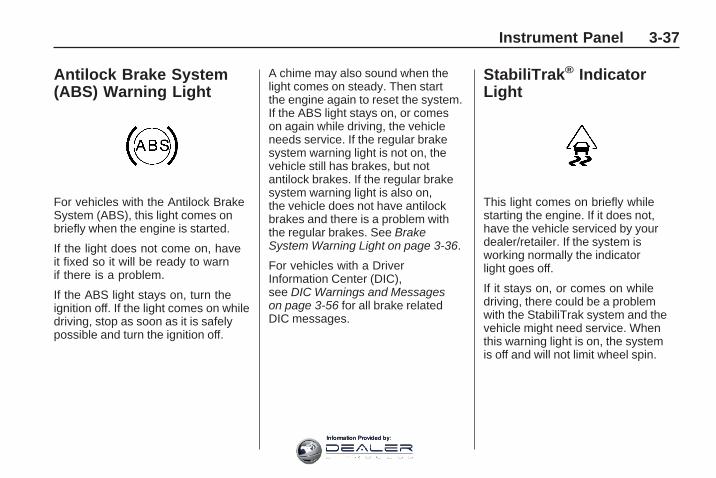
Antilock Brake System(ABS) Warning Light
For vehicles with the Antilock BrakeSystem (ABS), this light comes onbriefly when the engine is started.
If the light does not come on, haveit fixed so it will be ready to warnif there is a problem.
If the ABS light stays on, turn theignition off. If the light comes on whiledriving, stop as soon as it is safelypossible and turn the ignition off.
A chime may also sound when thelight comes on steady. Then startthe engine again to reset the system.If the ABS light stays on, or comeson again while driving, the vehicleneeds service. If the regular brakesystem warning light is not on, thevehicle still has brakes, but notantilock brakes. If the regular brakesystem warning light is also on,the vehicle does not have antilockbrakes and there is a problem withthe regular brakes. See BrakeSystem Warning Light on page 3-36.
For vehicles with a DriverInformation Center (DIC),see DIC Warnings and Messageson page 3-56 for all brake relatedDIC messages.
StabiliTrak® IndicatorLight
This light comes on briefly whilestarting the engine. If it does not,have the vehicle serviced by yourdealer/retailer. If the system isworking normally the indicatorlight goes off.
If it stays on, or comes on whiledriving, there could be a problemwith the StabiliTrak system and thevehicle might need service. Whenthis warning light is on, the systemis off and will not limit wheel spin.
Instrument Panel 3-37
Information Provided by:

This light flashes when theStabiliTrak system is active.
If the StabiliTrak system warninglight comes on and stays on foran extended period of time whenthe system is turned on, the vehicleneeds service. See StabiliTrak®
System on page 4-5 for moreinformation.
Engine CoolantTemperature WarningLight
The engine coolant temperaturewarning light comes on whenthe engine has overheated.
If this happens pull over and turnoff the engine as soon as possible.See Engine Overheating onpage 5-22 for more information.
Notice: Driving with the enginecoolant temperature warning lighton could cause the vehicle tooverheat. See Engine Overheatingon page 5-22. The vehicle’s enginecould be damaged, and it mightnot be covered by the vehiclewarranty. Never drive with theengine coolant temperaturewarning light on.
This light also comes on brieflywhen starting the vehicle. If it doesnot, see your dealer/retailer.
Engine CoolantTemperature Gage
This gage shows the enginecoolant temperature. If the gagepointer moves into the red area,it means that the engine coolanthas overheated. If the vehicle hasbeen operated under normal drivingconditions, pull off the road, stop thevehicle, and turn off the engine assoon as possible.
See Engine Overheating onpage 5-22 for more information.
United States Canada
3-38 Instrument Panel
Information Provided by:

Tire Pressure Light
If the vehicle has a tire pressuremonitoring system, the tire pressurelight provides information about tirepressures and the Tire PressureMonitoring System. The light shouldcome on briefly as the engine isstarted. If it does not, have thevehicle serviced by your dealer/retailer.
When the Light is On Steady
This indicates that one ormore of the tires are significantlyunderinflated.
A tire pressure message in theDriver Information Center (DIC),can accompany the light. See DICWarnings and Messages onpage 3-56 for more information.Stop and check the tires as soonas it is safe to do so. If underinflated,inflate to the proper pressure.See Tires on page 5-36 for moreinformation.
When the Light Flashes First andThen is On Steady
This indicates that there could bea problem with the Tire PressureMonitor System. The light flashes forabout a minute and stays on steadyfor the remainder of the ignitioncycle. This sequence repeats withevery ignition cycle. See TirePressure Monitor System onpage 5-43 for more information.
MalfunctionIndicator LampCheck Engine LightA computer system called OBD II(On-Board Diagnostics-SecondGeneration) monitors operationof the fuel, ignition, and emissioncontrol systems. It ensures thatemissions are at acceptable levelsfor the life of the vehicle, helping toproduce a cleaner environment.
This light comes on when theignition is on, but the engine is notrunning, as a check to show it isworking. If it does not, have thevehicle serviced by your dealer/retailer.
Instrument Panel 3-39
Information Provided by:
If the check engine light comes onand stays on, while the engineis running, this indicates that thereis an OBD II problem and serviceis required.
Malfunctions often are indicated bythe system before any problem isapparent. Being aware of the lightcan prevent more serious damageto the vehicle. This system assiststhe service technician in correctlydiagnosing any malfunction.
Notice: If the vehicle iscontinually driven with thislight on, after a while, theemission controls might notwork as well, the vehicle’s fueleconomy might not be as good,and the engine might not run assmoothly. This could lead tocostly repairs that might not becovered by the vehicle warranty.
Notice: Modifications made tothe engine, transmission, exhaust,intake, or fuel system of thevehicle or the replacement of theoriginal tires with other than thoseof the same Tire PerformanceCriteria (TPC) can affect thevehicle’s emission controls andcan cause this light to come on.Modifications to these systemscould lead to costly repairs notcovered by the vehicle warranty.This could also result in a failureto pass a required EmissionInspection/Maintenance test.See Accessories andModifications on page 5-3.
This light comes on during amalfunction in one of two ways:
Light Flashing: A misfire conditionhas been detected. A misfireincreases vehicle emissions andcould damage the emission controlsystem on the vehicle. Diagnosisand service might be required.
The following can prevent moreserious damage to the vehicle:
• Reduce vehicle speed.
• Avoid hard accelerations.
• Avoid steep uphill grades.
• If towing a trailer, reduce theamount of cargo being hauledas soon as it is possible.
If the light continues to flash, whenit is safe to do so, stop the vehicle.Find a safe place to park the vehicle.Turn the key off, wait at least10 seconds, and restart the engine.If the light is still flashing, follow theprevious steps and see your dealer/retailer for service as soon aspossible.
3-40 Instrument Panel
Information Provided by:

Light On Steady: An emissioncontrol system malfunction has beendetected on the vehicle. Diagnosisand service might be required.
An emission system malfunctionmight be corrected by checking thefollowing items:
• Make sure the fuel cap is fullyinstalled. See Filling the Tankon page 5-7. The diagnosticsystem can determine if the fuelcap has been left off or improperlyinstalled. A loose or missing fuelcap allows fuel to evaporate intothe atmosphere. A few drivingtrips with the cap properlyinstalled should turn the light off.
• If the vehicle has been driventhrough a deep puddle of water,the vehicle’s electrical systemmight be wet. The condition isusually corrected when theelectrical system dries out.A few driving trips should turnthe light off.
• Make sure to fuel the vehiclewith quality fuel. Poor fuel qualitycauses the engine not to run asefficiently as designed and maycause: stalling after start-up,stalling when the vehicle ischanged into gear, misfiring,hesitation on acceleration,or stumbling on acceleration.These conditions might go awayonce the engine is warmed up.
If one or more of these conditionsoccurs, change the fuel brandused. It will require at least onefull tank of the proper fuel to turnthe light off.See Gasoline Octane onpage 5-5.
If none of the above have made thelight turn off, your dealer/retailer cancheck the vehicle. The dealer/retailerhas the proper test equipment anddiagnostic tools to fix any mechanicalor electrical problems that mighthave developed.
Instrument Panel 3-41
Information Provided by:

Emissions Inspection andMaintenance ProgramsSome state/provincial and localgovernments have or might beginprograms to inspect the emissioncontrol equipment on the vehicle.Failure to pass this inspectioncould prevent getting a vehicleregistration.
Here are some things to know tohelp the vehicle pass an inspection:
• The vehicle will not pass thisinspection if the check enginelight is on with the enginerunning, or if the key is inON/RUN and the light is not on.
• The vehicle will not pass thisinspection if the OBD II (on-boarddiagnostic) system determinesthat critical emission controlsystems have not beencompletely diagnosed by thesystem. The vehicle wouldbe considered not ready for
inspection. This can happenif the battery has recently beenreplaced or if the battery has rundown. The diagnostic systemis designed to evaluate criticalemission control systems duringnormal driving. This can takeseveral days of routine driving.If this has been done and thevehicle still does not pass theinspection for lack of OBD IIsystem readiness, your dealer/retailer can prepare the vehiclefor inspection.
Oil Pressure Light
{ CAUTION
Do not keep driving if the oilpressure is low. The engine canbecome so hot that it catches fire.Someone could be burned. Checkthe oil as soon as possible andhave the vehicle serviced.
Notice: Lack of proper engineoil maintenance can damagethe engine. The repairs wouldnot be covered by the vehiclewarranty. Always follow themaintenance schedule in thismanual for changing engine oil.
The oil pressure light should comeon briefly as the engine is started. If itdoes not come on have the vehicleserviced by your dealer/retailer.
If the light comes on and stays on, itmeans that oil is not flowing throughthe engine properly. The vehiclecould be low on oil and might havesome other system problem.
3-42 Instrument Panel
Information Provided by:

Security Light
This light flashes when the securitysystem is activated.
For more information, seeTheft-Deterrent Systems onpage 2-16.
Cruise Control Light
This light comes on whenever thecruise control is set.
The light goes out when the cruisecontrol is turned off. See CruiseControl on page 3-9 for moreinformation.
Highbeam On Light
The highbeam on light comes onwhen the high-beam headlamps arein use.
See Headlamp High/Low-BeamChanger on page 3-7 for moreinformation.
Tow/Haul Mode Light
This light comes on when theTow/Haul mode has been activated.
For more information, seeTow/Haul Mode on page 2-26.
Fuel Gage
When the ignition is on, the fuelgage indicates about how much fuelthe vehicle has left in the fuel tank.
United States Canada
Instrument Panel 3-43
Information Provided by:

An arrow on the fuel gage indicatesthe side of the vehicle the fueldoor is on.
Here are four things that someowners ask about. None of theseshow a problem with the fuel gage:
• At the gas station, the gaspump shuts off before the gagereads full.
• It takes a little more or less fuelto fill up than the gage indicated.For example, the gage might haveindicated the tank was half full,but it actually took a little more orless than half the tank’s capacityto fill the tank.
• The gage moves a little whileturning a corner or speeding up.
• The gage does not go back toempty when the ignition isturned off.
Driver InformationCenter (DIC)Your vehicle has a DriverInformation Center (DIC).
The DIC displays information aboutyour vehicle. It also displays warningmessages if a system problem isdetected.
All messages will appear in the DICdisplay located at the top of theinstrument panel cluster.
The DIC comes on when theignition is on. After a short delay,the DIC will display the informationthat was last displayed beforethe engine was turned off.
The DIC also displays a shift leverposition indicator on the bottomline of the display. See AutomaticTransmission Operation onpage 2-24 for more information.
The outside air temperatureand compass, if equipped, alsodisplays on the DIC when viewingthe trip and fuel information.
The outside air temperatureautomatically appears in the topright corner of the DIC display.If there is a problem with the systemthat controls the temperature display,the numbers will be replaced withdashes. If this occurs, have thevehicle serviced. The compasswill be shown in the bottom rightcorner of the DIC display. See DICCompass on page 3-54 for moreinformation.
If your vehicle has DIC buttons,see “DIC Operation and Displays(With DIC Buttons)” later inthis section and DIC VehicleCustomization (With DIC Buttons) onpage 3-65 for the displays available.
If your vehicle does not haveDIC buttons, see “DIC Operationand Displays (Without DIC Buttons)”later in this section for the displaysavailable.
3-44 Instrument Panel
Information Provided by:

DIC Operation andDisplays (With DICButtons)If your vehicle has DIC buttons,the information below explains theoperation of this system.
The DIC has different displayswhich can be accessed by pressingthe DIC buttons located on theinstrument panel. See InstrumentPanel Overview on page 3-4for more information.
The DIC displays trip, fuel, andvehicle system information, andwarning messages if a systemproblem is detected.
The DIC also allows some featuresto be customized. See DIC VehicleCustomization (With DIC Buttons)on page 3-65 for more information.
If your vehicle has DIC buttons,you can also use the trip odometerreset stem to view the odometerand trip odometers.
DIC Buttons
The buttons are the set/reset,customization, vehicle information,and trip/fuel buttons. The buttonfunctions are detailed in thefollowing pages.
V (Set/Reset): Press this button toset or reset certain functions and toturn off or acknowledge messageson the DIC.
U (Customization): Press thisbutton to customize the featuresettings on your vehicle. See DICVehicle Customization (With DICButtons) on page 3-65 for moreinformation.
T (Vehicle Information): Pressthis button to display the oil life, parkassist on vehicles with this feature,units, tire pressure readings onvehicles with the Tire PressureMonitor System (TPMS), RemoteKeyless Entry (RKE) transmitterprogramming, and compasscalibration and zone setting onvehicles with this feature.
3 (Trip/Fuel): Press thisbutton to display the odometer,trip odometers, fuel range, averageeconomy, fuel economy, timer,fuel used, and average speed.
Instrument Panel 3-45
Information Provided by:

Vehicle Information MenuItems
T (Vehicle Information): Pressthis button to scroll through thefollowing menu items:
OIL LIFE
Press the vehicle information buttonuntil OIL LIFE REMAINING displays.This display shows an estimate ofthe oil’s remaining useful life. If yousee 99% OIL LIFE REMAINING onthe display, that means 99% of thecurrent oil life remains. The engineoil life system will alert you to changethe oil on a schedule consistent withyour driving conditions.
When the remaining oil life is low,the CHANGE ENGINE OIL SOONmessage will appear on the display.See “CHANGE ENGINE OIL SOON”under DIC Warnings and Messageson page 3-56. You should changethe oil as soon as you can.See Engine Oil on page 5-11.
In addition to the engine oil lifesystem monitoring the oil life,additional maintenance isrecommended in the MaintenanceSchedule in this manual.See Scheduled Maintenanceon page 6-3 for more information.
Remember, you must reset theOIL LIFE display yourself after eachoil change. It will not reset itself.Also, be careful not to reset theOIL LIFE display accidentally at anytime other than when the oil has justbeen changed. It cannot be resetaccurately until the next oil change.To reset the engine oil life system,see Engine Oil Life System onpage 5-13.
PARK ASSIST
If your vehicle has the UltrasonicRear Parking Assist (URPA) system,press the vehicle information buttonuntil PARK ASSIST displays.This display allows the systemto be turned on or off. Once in thisdisplay, press the set/reset button to
select between ON or OFF. If youchoose ON, the system will be turnedon. If you choose OFF, the systemwill be turned off. The URPA systemautomatically turns back on aftereach vehicle start. When the URPAsystem is turned off and the vehicleis shifted out of P (Park), the DICwill display the PARK ASSIST OFFmessage as a reminder that thesystem has been turned off.See DIC Warnings and Messageson page 3-56 and Ultrasonic RearParking Assist (URPA) on page 2-36for more information.
UNITS
Press the vehicle information buttonuntil UNITS displays. This displayallows you to select between Englishor Metric units of measurement.Once in this display, press theset/reset button to select betweenENGLISH or METRIC units. All ofthe vehicle information will then bedisplayed in the unit of measurementselected.
3-46 Instrument Panel
Information Provided by:

FRONT TIRES or REAR TIRES
On vehicles with the Tire PressureMonitor System (TPMS), thepressure for each tire can be viewedin the DIC. The tire pressure will beshown in either pounds per squareinch (psi) or kilopascals (kPa). Pressthe vehicle information button untilthe DIC displays FRONT TIRESPSI (kPa) LEFT ## RIGHT ##. Pressthe vehicle information button againuntil the DIC displays REAR TIRESPSI (kPa) LEFT ## RIGHT ##.
If a low or high tire pressurecondition is detected by the systemwhile driving, a message advisingyou to check the pressure in aspecific tire will appear in the display.See Inflation - Tire Pressure onpage 5-42 and DIC Warnings andMessages on page 3-56 for moreinformation.
If the tire pressure display showsdashes instead of a value, theremay be a problem with your vehicle.If this consistently occurs, seeyour dealer/retailer for service.
RELEARN REMOTE KEY
This display allows you to matchRemote Keyless Entry (RKE)transmitters to your vehicle.This procedure will erase allpreviously learned transmitters.Therefore, they must be relearnedas additional transmitters.
To match an RKE transmitter toyour vehicle:
1. Press the vehicle informationbutton until PRESS V TORELEARN REMOTE KEYdisplays.
2. Press the set/reset button untilREMOTE KEY LEARNINGACTIVE is displayed.
3. Press and hold the lock andunlock buttons on the firsttransmitter at the same timefor about 15 seconds.On vehicles with memoryrecall seats, the first transmitterlearned will match driver 1and the second will matchdriver 2.A chime will sound indicatingthat the transmitter is matched.
4. To match additional transmittersat this time, repeat Step 3.Each vehicle can have amaximum of eight transmittersmatched to it.
5. To exit the programming mode,you must cycle the key toLOCK/OFF.
Instrument Panel 3-47
Information Provided by:

COMPASS ZONE SETTING
This display will be availableif the vehicle has a compass.See DIC Compass on page 3-54for more information.
COMPASS RECALIBRATION
This display will be availableif the vehicle has a compass.See DIC Compass on page 3-54for more information.
Blank Display
This display shows no information.
Trip/Fuel Menu Items
3 (Trip/Fuel): Press this buttonto scroll through the followingmenu items:
ODOMETER
Press the trip/fuel button untilODOMETER displays. This displayshows the distance the vehicle hasbeen driven in either miles (mi) orkilometers (km). Pressing the tripodometer reset stem will alsodisplay the odometer.
To switch between English andmetric measurements, see “UNITS”earlier in this section.
TRIP A and TRIP B
Press the trip/fuel button untilTRIP A or TRIP B displays.This display shows the currentdistance traveled in either miles (mi)or kilometers (km) since the lastreset for each trip odometer.Both trip odometers can be usedat the same time. Pressing the tripodometer reset stem will alsodisplay the trip odometers.
Each trip odometer can be resetto zero separately by pressing theset/reset button or the trip odometerreset stem while the desired tripodometer is displayed.
3-48 Instrument Panel
Information Provided by:

The trip odometer has a featurecalled the retro-active reset.This can be used to set the tripodometer to the number of miles(kilometers) driven since the ignitionwas last turned on. This can beused if the trip odometer is notreset at the beginning of the trip.
To use the retro-active reset feature,press and hold the set/reset buttonfor at least four seconds. The tripodometer will display the number ofmiles (mi) or kilometers (km) drivensince the ignition was last turned onand the vehicle was moving. Oncethe vehicle begins moving, the tripodometer will accumulate mileage.For example, if the vehicle wasdriven 5 miles (8 km) before itis started again, and then theretro-active reset feature is activated,the display will show 5 miles (8 km).As the vehicle begins moving, thedisplay will then increase to 5.1 miles(8.2 km), 5.2 miles (8.4 km), etc.
If the retro-active reset feature isactivated after the vehicle is started,but before it begins moving, thedisplay will show the number ofmiles (mi) or kilometers (km) thatwere driven during the last ignitioncycle.
RANGE
Press the trip/fuel button untilRANGE displays. This displayshows the approximate numberof remaining miles (mi) orkilometers (km) the vehicle can bedriven without refueling. The displaywill show LOW if the fuel level is low.
The fuel range estimate is basedon an average of the vehicle’s fueleconomy over recent driving historyand the amount of fuel remainingin the fuel tank. This estimate willchange if driving conditions change.For example, if driving in traffic andmaking frequent stops, this display
may read one number, but if thevehicle is driven on a freeway, thenumber may change even thoughthe same amount of fuel is in the fueltank. This is because different drivingconditions produce different fueleconomies. Generally, freewaydriving produces better fuel economythan city driving. Fuel range cannotbe reset.
AVG (Average) ECONOMY
Press the trip/fuel button untilAVG ECONOMY displays.This display shows the approximateaverage miles per gallon (mpg) orliters per 100 kilometers (L/100 km).This number is calculated basedon the number of mpg (L/100 km)recorded since the last time thismenu item was reset. To resetAVG ECONOMY, press and holdthe set/reset button.
Instrument Panel 3-49
Information Provided by:

FUEL ECONOMY
Press the trip/fuel button untilFUEL ECONOMY displays.The FUEL ECONOMY displayshows an estimate of the vehiclefuel economy under a given drivingcondition at a specific moment.For example, if the vehicle isaccelerating and achieving low fuelefficiency this display will show fewerbars, but if the vehicle is cruising ona flat freeway and getting high fuelefficiency, the display will show morebars. Fuel economy cannot be reset.
TIMER
Press the trip/fuel button untilTIMER displays. This displaycan be used as a timer.
To start the timer, press theset/reset button while TIMER isdisplayed. The display will showthe amount of time that has passedsince the timer was last reset, notincluding time the ignition is off.Time will continue to be countedas long as the ignition is on, evenif another display is being shownon the DIC. The timer will recordup to 99 hours, 59 minutes and59 seconds (99:59:59) after whichthe display will return to zero.
To stop the timer, press the set/resetbutton briefly while TIMER isdisplayed.
To reset the timer to zero, pressand hold the set/reset button whileTIMER is displayed.
FUEL USED
Press the trip/fuel button untilFUEL USED displays. This displayshows the number of gallons (gal) orliters (L) of fuel used since the lastreset of this menu item. To resetthe fuel used information, pressand hold the set/reset button whileFUEL USED is displayed.
AVG (Average) SPEED
Press the trip/fuel button untilAVG SPEED displays. This displayshows the average speed of thevehicle in miles per hour (mph)or kilometers per hour (km/h).This average is calculated basedon the various vehicle speedsrecorded since the last reset of thisvalue. To reset the value to zero,press and hold the set/reset button.
Blank Display
This display shows no information.
3-50 Instrument Panel
Information Provided by:

DIC Operation andDisplays (Without DICButtons)If your vehicle does not have DICbuttons, the information belowexplains the operation of this system.
The DIC has different displays whichcan be accessed by pressing the tripodometer reset stem located on theinstrument panel cluster. Pressingthe trip odometer reset stem willalso turn off, or acknowledge,DIC messages.
The DIC displays trip and vehiclesystem information, and warningmessages if a system problemis detected.
If your vehicle does not haveDIC buttons, you can use the tripodometer reset stem to view thefollowing displays: odometer, trip
odometers, oil life, park assist menufor vehicles with the UltrasonicRear Parking Assist (URPA) system,Remote Keyless Entry (RKE)transmitter programming, units,and display language.
If your vehicle has DIC buttons,you can use the trip odometer resetstem to view the following displays:odometer and trip odometers.
Trip Odometer Reset StemMenu ItemsODOMETER
Press the trip odometer resetstem until ODOMETER displays.This display shows the distance thevehicle has been driven in eithermiles (mi) or kilometers (km).
To switch between English andmetric measurements, see “UNITS”later in this section.
TRIP A or TRIP B
Press the trip odometer reset stemuntil TRIP A or TRIP B displays.This display shows the currentdistance traveled in either miles (mi)or kilometers (km) since the lastreset for each trip odometer. Bothtrip odometers can be used at thesame time.
Each trip odometer can be reset tozero separately by pressing andholding the trip odometer reset stemwhile the desired trip odometer isdisplayed.
The trip odometer has a featurecalled the retro-active reset. This canbe used to set the trip odometer tothe number of miles (kilometers)driven since the ignition was lastturned on. This can be used if thetrip odometer is not reset at thebeginning of the trip.
Instrument Panel 3-51
Information Provided by:

To use the retro-active reset feature,press and hold the trip odometerreset stem for at least four seconds.The trip odometer will displaythe number of miles (mi) orkilometers (km) driven since theignition was last turned on andthe vehicle was moving. Once thevehicle begins moving, the tripodometer will accumulate mileage.For example, if the vehicle wasdriven 5 miles (8 km) before itis started again, and then theretro-active reset feature is activated,the display will show 5 miles (8 km).As the vehicle begins moving, thedisplay will then increase to 5.1 miles(8.2 km), 5.2 miles (8.4 km), etc.
If the retro-active reset featureis activated after the vehicle isstarted, but before it begins moving,the display will show the number ofmiles (mi) or kilometers (km) thatwere driven during the last ignitioncycle.
OIL LIFE
To access this display, the vehiclemust be in P (Park). Press the tripodometer reset stem until OIL LIFEREMAINING displays. This displayshows an estimate of the oil’sremaining useful life. If you see99% OIL LIFE REMAINING onthe display, that means 99% of thecurrent oil life remains. The engineoil life system will alert you to changethe oil on a schedule consistent withyour driving conditions.
When the remaining oil life is low,the CHANGE ENGINE OIL SOONmessage will appear on the display.See “CHANGE ENGINE OIL SOON”under DIC Warnings and Messageson page 3-56. You should changethe oil as soon as you can.See Engine Oil on page 5-11.
In addition to the engine oil lifesystem monitoring the oil life,additional maintenance isrecommended in the MaintenanceSchedule in this manual.See Scheduled Maintenance onpage 6-3 for more information.
Remember, you must reset theOIL LIFE display yourself after eachoil change. It will not reset itself.Also, be careful not to reset theOIL LIFE display accidentally at anytime other than when the oil has justbeen changed. It cannot be resetaccurately until the next oil change.To reset the engine oil life system,see Engine Oil Life System onpage 5-13.
3-52 Instrument Panel
Information Provided by:

PARK ASSIST
To access this display, the vehiclemust be in P (Park). If your vehiclehas the Ultrasonic Rear ParkingAssist (URPA) system, press the tripodometer reset stem until PARKASSIST displays. This display allowsthe system to be turned on or off.Once in this display, press and holdthe trip odometer reset stem to selectbetween ON or OFF. If you chooseON, the system will be turned on.If you choose OFF, the system willbe turned off. The URPA systemautomatically turns back on aftereach vehicle start. When the URPAsystem is turned off and the vehicleis shifted out of P (Park), the DICwill display the PARK ASSIST OFFmessage as a reminder that thesystem has been turned off.See DIC Warnings and Messageson page 3-56 and Ultrasonic RearParking Assist (URPA) on page 2-36for more information.
RELEARN REMOTE KEY
To access this display, the vehiclemust be in P (Park). This displayallows you to match Remote KeylessEntry (RKE) transmitters to yourvehicle. This procedure will eraseall previously learned transmitters.Therefore, they must be relearnedas additional transmitters.
To match an RKE transmitter toyour vehicle:
1. Press the trip odometer resetstem until RELEARN REMOTEKEY displays.
2. Press and hold the trip odometerreset stem until REMOTE KEYLEARNING ACTIVE is displayed.
3. Press and hold the lock andunlock buttons on the firsttransmitter at the same timefor about 15 seconds.On vehicles with memory recallseats, the first transmitter learnedwill match driver 1 and thesecond will match driver 2.
A chime will sound indicatingthat the transmitter is matched.
4. To match additional transmittersat this time, repeat Step 3.Each vehicle can have amaximum of eight transmittersmatched to it.
5. To exit the programming mode,you must cycle the key toLOCK/OFF.
UNITS
To access this display, the vehiclemust be in P (Park). Press the tripodometer reset stem until UNITSdisplays. This display allows you toselect between English or Metricunits of measurement. Once inthis display, press and hold thetrip odometer reset stem to selectbetween ENGLISH or METRIC units.All of the vehicle information willthen be displayed in the unit ofmeasurement selected.
Instrument Panel 3-53
Information Provided by:

DISPLAY LANGUAGE
To access this display, the vehiclemust be in P (Park). This displayallows you to select the languagein which the DIC messages willappear. To select a language:
1. Press the trip odometer resetstem until DISPLAY LANGUAGEdisplays.
2. Continue to press and hold thetrip odometer reset stem to scrollthrough all of the availablelanguages.The available languages areENGLISH (default), FRANCAIS(French), ESPANOL (Spanish),and NO CHANGE.
3. Once the desired languageis displayed, release the tripodometer reset stem to setyour choice.
DIC CompassYour vehicle may have acompass in the Driver InformationCenter (DIC).
Compass Zone
The zone is set to zone eight uponleaving the factory. Your dealer/retailer will set the correct zonefor your location.
Under certain circumstances,such as during a long distancecross-country trip or moving to a newstate or province, it will be necessaryto compensate for compass varianceby resetting the zone through theDIC if the zone is not set correctly.
Compass variance is the differencebetween the earth’s magnetic northand true geographic north. If thecompass is not set to the zone whereyou live, the compass may give falsereadings. The compass must be setto the variance zone in which thevehicle is traveling.
To adjust for compass variance, usethe following procedure:
Compass Variance (Zone)Procedure1. Do not set the compass zone
when the vehicle is moving.Only set it when the vehicleis in P (Park).Press the vehicle informationbutton until PRESS V TOCHANGE COMPASS ZONEdisplays.
2. Find the vehicle’s currentlocation and variance zonenumber on the map.Zones 1 through 15 are available.
3-54 Instrument Panel
Information Provided by:

3. Press the set/reset button toscroll through and select theappropriate variance zone.
4. Press the trip/fuel button untilthe vehicle heading, for example,N for North, is displayed inthe DIC.
5. If calibration is necessary,calibrate the compass.See “Compass CalibrationProcedure” following.
Compass Calibration
The compass can be manuallycalibrated. Only calibrate thecompass in a magnetically cleanand safe location, such as anopen parking lot, where drivingthe vehicle in circles is not a danger.It is suggested to calibrate away fromtall buildings, utility wires, manholecovers, or other industrial structures,if possible.
If CAL should ever appear in theDIC display, the compass shouldbe calibrated.
If the DIC display does not show aheading, for example, N for North,or the heading does not change aftermaking turns, there may be a strongmagnetic field interfering with thecompass. Such interference maybe caused by a magnetic CB or cellphone antenna mount, a magneticemergency light, magnetic note padholder, or any other magnetic item.Turn off the vehicle, move themagnetic item, then turn on thevehicle and calibrate the compass.
To calibrate the compass, use thefollowing procedure:
Compass Calibration Procedure
1. Before calibrating the compass,make sure the compass zoneis set to the variance zone inwhich the vehicle is located.See “Compass Variance (Zone)Procedure” earlier in this section.
Do not operate any switchessuch as window, sunroof, climatecontrols, seats, etc. during thecalibration procedure.
2. Press the vehicle informationbutton until PRESS V TOCALIBRATE COMPASSdisplays.
3. Press the set/reset button to startthe compass calibration.
4. The DIC will displayCALIBRATING: DRIVE INCIRCLES. Drive the vehiclein tight circles at less than5 mph (8 km/h) to complete thecalibration. The DIC will displayCALIBRATION COMPLETE for afew seconds when the calibrationis complete. The DIC display willthen return to the previous menu.
Instrument Panel 3-55
Information Provided by:
DIC Warnings andMessagesMessages are displayed on the DICto notify the driver that the status ofthe vehicle has changed and thatsome action may be needed bythe driver to correct the condition.Multiple messages may appearone after another.
Some messages may not requireimmediate action, but you canpress any of the DIC buttons on theinstrument panel or the trip odometerreset stem on the instrument panelcluster to acknowledge that youreceived the messages and toclear them from the display.
Some messages cannot be clearedfrom the DIC display because theyare more urgent. These messagesrequire action before they can be
cleared. You should take anymessages that appear on the displayseriously and remember that clearingthe messages will only make themessages disappear, not correctthe problem.
The following are the possiblemessages that can be displayedand some information about them.
ALL WHEEL DRIVE OFFIf your vehicle has the All-WheelDrive (AWD) system, this messagedisplays when there is a compactspare tire on the vehicle, whenthe Antilock Brake System (ABS)warning light comes on, or when therear differential fluid is overheating.This message turns off whenthe differential fluid cools.
The AWD system is disabled untilthe compact spare tire is replacedby a full-size tire. If the warning
message is still on after putting onthe full-size tire, you need to resetthe warning message. To reset thewarning message, turn the ignitionoff and then back on again after30 seconds. If the message stays on,see your dealer/retailer right away.See All-Wheel Drive (AWD) Systemon page 4-7 for more information.
AUTOMATIC LIGHTCONTROL OFFThis message displays when theautomatic headlamps are turned off.This message clears itself after10 seconds.
AUTOMATIC LIGHTCONTROL ONThis message displays when theautomatic headlamps are turned on.This message clears itself after10 seconds.
3-56 Instrument Panel
Information Provided by:

BATTERY SAVER ACTIVEThis message displays when thesystem detects that the batteryvoltage is dropping below expectedlevels. The battery saver systemstarts reducing certain features ofthe vehicle that you may be able tonotice. At the point that the featuresare disabled, this message isdisplayed. It means that the vehicleis trying to save the charge in thebattery.
Turn off all unnecessary accessoriesto allow the battery to recharge.
The normal battery voltagerange is 11.5 to 15.5 volts.
CHANGE ENGINE OIL SOONThis message displays when theengine oil needs to be changed.When you change the engine oil, besure to reset the CHANGE ENGINEOIL SOON message. See EngineOil Life System on page 5-13 forinformation on how to reset themessage. See Engine Oil onpage 5-11 and ScheduledMaintenance on page 6-3 formore information.
CHECK TIRE PRESSUREOn vehicles with the Tire PressureMonitor System (TPMS), thismessage displays when the pressurein one or more of the vehicle’s tiresneeds to be checked. This messagealso displays LEFT FRONT, RIGHTFRONT, LEFT REAR, or RIGHTREAR to indicate which tire needs tobe checked. You can receive morethan one tire pressure message ata time. To read the other messages
that may have been sent at the sametime, press the set/reset button orthe trip odometer reset stem. If a tirepressure message appears on theDIC, stop as soon as you can. Havethe tire pressures checked and setto those shown on the Tire LoadingInformation label. See Tires onpage 5-36, Loading the Vehicleon page 4-16, and Inflation - TirePressure on page 5-42. The DICalso shows the tire pressure values.See “DIC Operation and Displays(With DIC Buttons)” earlier in thissection. If the tire pressure is low,the low tire pressure warning lightcomes on. See Tire Pressure Lighton page 3-39.
CRUISE SET TO XXXThis message displays wheneverthe cruise control is set. See CruiseControl on page 3-9 for moreinformation.
Instrument Panel 3-57
Information Provided by:

DRIVER DOOR OPENThis message displays and achime sounds if the driver dooris not fully closed and the vehicleis shifted out of P (Park). Stop andturn off the vehicle, check the doorfor obstructions, and close the dooragain. Check to see if the messagestill appears on the DIC.
ENGINE HOT A/C(Air Conditioning) OFFThis message displays when theengine coolant becomes hotter thanthe normal operating temperature.See Engine Coolant TemperatureGage on page 3-38. To avoidadded strain on a hot engine,the air conditioning compressorautomatically turns off. When thecoolant temperature returns tonormal, the air conditioningcompressor turns back on. Youcan continue to drive your vehicle.
If this message continues to appear,have the system repaired by yourdealer/retailer as soon as possibleto avoid damage to the engine.
ENGINE OVERHEATED IDLEENGINE
Notice: If you drive your vehiclewhile the engine is overheating,severe engine damage may occur.If an overheat warning appearson the instrument panel clusterand/or DIC, stop the vehicle assoon as possible. Do not increasethe engine speed above normalidling speed. See EngineOverheating on page 5-22 formore information.
This message displays when theengine coolant temperature is toohot. Stop and allow the vehicle toidle until it cools down. See EngineCoolant Temperature Gage onpage 3-38.
See Overheated Engine ProtectionOperating Mode on page 5-23for information on driving to asafe place in an emergency.
ENGINE OVERHEATED STOPENGINE
Notice: If you drive your vehiclewhile the engine is overheating,severe engine damage may occur.If an overheat warning appearson the instrument panel clusterand/or DIC, stop the vehicleas soon as possible. See EngineOverheating on page 5-22 formore information.
This message displays and acontinuous chime sounds if theengine cooling system reachesunsafe temperatures for operation.Stop and turn off the vehicle assoon as it is safe to do so to avoidsevere damage. This messageclears when the engine has cooledto a safe operating temperature.
3-58 Instrument Panel
Information Provided by:

ENGINE POWER IS REDUCEDThis message displays and achime sounds when the coolingsystem temperature gets too hotand the engine further entersthe engine coolant protection mode.See Engine Overheating onpage 5-22 for further information.
This message also displays whenthe vehicle’s engine power isreduced. Reduced engine powercan affect the vehicle’s ability toaccelerate. If this message is on,but there is no reduction inperformance, proceed to yourdestination. The performancemay be reduced the next timethe vehicle is driven. The vehiclemay be driven at a reduced speedwhile this message is on, butacceleration and speed may bereduced. Anytime this messagestays on, the vehicle should betaken to your dealer/retailer forservice as soon as possible.
FUEL LEVEL LOWThis message displays and a chimesounds if the fuel level is low. Refuelas soon as possible. See Fuel Gageon page 3-43 and Fuel on page 5-5for more information.
HEATED WASH (Washer)FLUID SYSTEM OFFThis message displays whenyou manually turn off the heatedwindshield washer fluid system orwhen the system automatically turnsoff. See “Heated Windshield Washer”under Windshield Washer onpage 3-8 for more information.This message clears itself after10 seconds.
HEATING WASH (Washer)FLUID WASH (Washer) WIPESPENDINGThis message displays whenyou turn on the heated windshieldwasher fluid system. See “HeatedWindshield Washer” underWindshield Washer on page 3-8for more information.
HOOD OPENOn some models, this messagedisplays and a chime sounds if thehood is not fully closed. Stop andturn off the vehicle, check the hoodfor obstructions, and close the hoodagain. Check to see if the messagestill appears on the DIC.
ICE POSSIBLE DRIVEWITH CAREThis message displays when theoutside air temperature is coldenough to create icy road conditions.Adjust your driving accordingly.
Instrument Panel 3-59
Information Provided by:

LEFT REAR DOOR OPENThis message displays and a chimesounds if the driver side rear dooris not fully closed and the vehicle isshifted out of P (Park). Stop and turnoff the vehicle, check the door forobstructions, and close the dooragain. Check to see if the messagestill appears on the DIC.
LIFTGATE OPENThis message displays and a chimesounds if the liftgate is open whilethe ignition is in ON/RUN. Turn offthe vehicle and check the liftgate.Restart the vehicle and check forthe message on the DIC display.
OIL PRESSURE LOW STOPENGINE
Notice: If you drive your vehiclewhile the engine oil pressure islow, severe engine damage mayoccur. If a low oil pressurewarning appears on the DriverInformation Center (DIC), stopthe vehicle as soon as possible.Do not drive the vehicle until thecause of the low oil pressure iscorrected. See Engine Oil onpage 5-11 for more information.
This message displays if low oilpressure levels occur. Stop thevehicle as soon as safely possibleand do not operate it until the causeof the low oil pressure has beencorrected. Check the oil as soonas possible and have your vehicleserviced by your dealer/retailer.See Engine Oil on page 5-11.
PARK ASSIST OFFIf your vehicle has the UltrasonicRear Parking Assist (URPA) system,after the vehicle has been startedand shifted out of P (Park), thismessage displays to remindthe driver that the URPA systemhas been turned off. Press theset/reset button or the trip odometerreset stem to acknowledge thismessage and clear it from the DICdisplay. To turn the URPA systemback on, see Ultrasonic RearParking Assist (URPA) onpage 2-36.
PASSENGER DOOR OPENThis message displays and a chimesounds if the passenger door isnot fully closed and the vehicle isshifted out of P (Park). Stop and turnoff the vehicle, check the door forobstructions, and close the dooragain. Check to see if the messagestill appears on the DIC.
3-60 Instrument Panel
Information Provided by:

REMOTE KEY LEARNINGACTIVEThis message displays while you arematching a Remote Keyless Entry(RKE) transmitter to your vehicle.See “Matching Transmitter(s) toYour Vehicle” under Remote KeylessEntry (RKE) System Operation onpage 2-4 and DIC Operation andDisplays (With DIC Buttons) onpage 3-45 or DIC Operation andDisplays (Without DIC Buttons)on page 3-51 for more information.
REPLACE BATTERY INREMOTE KEYThis message displays if a RemoteKeyless Entry (RKE) transmitterbattery is low. The battery needsto be replaced in the transmitter.See “Battery Replacement” underRemote Keyless Entry (RKE)System Operation on page 2-4.
RIGHT REAR DOOR OPENThis message displays and a chimesounds if the passenger side reardoor is not fully closed and thevehicle is shifted out of P (Park).Stop and turn off the vehicle, checkthe door for obstructions, and closethe door again. Check to see if themessage still appears on the DIC.
SERVICE A/C(Air Conditioning) SYSTEMThis message displays whenthe electronic sensors that controlthe air conditioning and heatingsystems are no longer working.Have the climate control systemserviced by your dealer/retailerif you notice a drop in heatingand air conditioning efficiency.
SERVICE AIR BAGThis message displays if there isa problem with the airbag system.Have your dealer/retailer inspect thesystem for problems. See AirbagReadiness Light on page 3-33 andAirbag System on page 1-46 formore information.
SERVICE ALL WHEEL DRIVEIf your vehicle has the All-WheelDrive (AWD) system, this messagedisplays if there is a problem withthis system. If this message appears,stop as soon as possible and turnoff the vehicle. Restart the vehicleafter 30 seconds and check for themessage on the DIC display. If themessage is still displayed or appearsagain when you begin driving, theAWD system needs service.See your dealer/retailer.
Instrument Panel 3-61
Information Provided by:

SERVICE BATTERYCHARGING SYSTEMOn some vehicles, this messagedisplays if there is a problem withthe battery charging system.Under certain conditions, thecharging system light may also turnon in the instrument panel cluster.See Charging System Light onpage 3-34. Driving with this problemcould drain the battery. Turn off allunnecessary accessories. Have theelectrical system checked as soonas possible. See your dealer/retailer.
SERVICE BRAKE SYSTEMThis message displays along withthe brake system warning light ifthere is a problem with the brakesystem. See Brake System WarningLight on page 3-36. If this messageappears, stop as soon as possibleand turn off the vehicle. Restart thevehicle and check for the messageon the DIC display. If the message isstill displayed or appears again when
you begin driving, the brake systemneeds service as soon as possible.See your dealer/retailer.
SERVICE PARK ASSISTIf your vehicle has the UltrasonicRear Parking Assist (URPA) system,this message displays if there is aproblem with the URPA system.Do not use this system to help youpark. See Ultrasonic Rear ParkingAssist (URPA) on page 2-36for more information. See yourdealer/retailer for service.
SERVICE POWER STEERINGThis message displays when aproblem is detected with the powersteering system. When this messageis displayed, you may notice that theeffort required to steer the vehicleincreases or feels heavier, but youwill still be able to steer the vehicle.Have your vehicle serviced by yourdealer/retailer immediately.
SERVICE STABILITRAKThis message displays if thereis a problem with the StabiliTrak®
system. If this message appears,try to reset the system. Stop; turn offthe engine for at least 15 seconds;then start the engine again. If thismessage still comes on, it meansthere is a problem. See your dealer/retailer for service. The vehicle issafe to drive, however, you do nothave the benefit of StabiliTrak,so reduce your speed and driveaccordingly.
SERVICE THEFT DETERRENTSYSTEMThis message displays when thereis a problem with the theft-deterrentsystem. The vehicle may or maynot restart so you may want to takethe vehicle to your dealer/retailerbefore turning off the engine.See PASS-Key® III+ ElectronicImmobilizer Operation on page 2-18for more information.
3-62 Instrument Panel
Information Provided by:

SERVICE TIRE MONITORSYSTEMOn vehicles with the Tire PressureMonitor System (TPMS), thismessage displays if a part on theTPMS is not working properly.The tire pressure light also flashesand then remains on during thesame ignition cycle. See TirePressure Light on page 3-39.Several conditions may cause thismessage to appear. See TirePressure Monitor Operation onpage 5-45 for more information.If the warning comes on and stayson, there may be a problem withthe TPMS. See your dealer/retailer.
SERVICE TRACTIONCONTROLThis message displays when thereis a problem with the Traction ControlSystem (TCS). When this messageis displayed, the system will notlimit wheel spin. Adjust your drivingaccordingly. See your dealer/retailerfor service. See StabiliTrak® Systemon page 4-5 for more information.
SERVICE TRANSMISSIONThis message displays when thereis a problem with the transmission.See your dealer/retailer for service.
SERVICE VEHICLE SOONThis message displays whena non-emissions related malfunctionoccurs. Have the vehicle servicedby your dealer/retailer as soonas possible.
SPEED LIMITED TOXXX MPH (KM/H)This message displays when yourvehicle speed is limited to 80 mph(128 km/h) because the vehicledetects a problem in the speedvariable assist steering system.Have your vehicle serviced byyour dealer/retailer.
STARTING DISABLEDSERVICE THROTTLEThis message displays when yourvehicle’s throttle system is notfunctioning properly. Have yourvehicle serviced by your dealer/retailer.
THEFT ATTEMPTEDThis message displays if the contenttheft-deterrent system has detecteda break-in attempt while you wereaway from your vehicle. See ContentTheft-Deterrent on page 2-16 formore information.
Instrument Panel 3-63
Information Provided by:
TIGHTEN GAS CAPThis message may display alongwith the check engine light on theinstrument panel cluster if thevehicle’s fuel cap is not tightenedproperly. See Malfunction IndicatorLamp on page 3-39. Reinstall thefuel cap fully. See Filling the Tankon page 5-7. The diagnostic systemcan determine if the fuel cap hasbeen left off or improperly installed.A loose or missing fuel capallows fuel to evaporate into theatmosphere. A few driving tripswith the cap properly installedshould turn this light andmessage off.
TIRE LEARNING ACTIVEOn vehicles with the Tire PressureMonitor System (TPMS), thismessage displays when the TPMSis re-learning the tire positions onyour vehicle. The tire positions mustbe re-learned after rotating the tiresor after replacing a tire or sensor.See Tire Inspection and Rotationon page 5-48, Tire PressureMonitor System on page 5-43,and Inflation - Tire Pressure onpage 5-42 for more information.
TRACTION CONTROL OFFThis message displays whenthe Traction Control System (TCS)is turned off. Adjust your drivingaccordingly. See StabiliTrak®
System on page 4-5 for moreinformation. This messageclears itself after 10 seconds.
TRANSMISSION HOT IDLEENGINE
Notice: If you drive your vehiclewhile the transmission fluid isoverheating and the transmissiontemperature warning is displayedon the instrument panel clusterand/or DIC, you can damage thetransmission. This could lead tocostly repairs that would not becovered by your warranty. Do notdrive your vehicle with overheatedtransmission fluid or while thetransmission temperature warningis displayed.
This message displays and a chimesounds if the transmission fluid in thevehicle gets hot. Driving with thetransmission fluid temperature highcan cause damage to the vehicle.Stop the vehicle and let it idle toallow the transmission to cool.This message clears when the fluidtemperature reaches a safe level.
3-64 Instrument Panel
Information Provided by:

TURN SIGNAL ONThis message displays and a chimesounds if a turn signal is left onfor 3/4 of a mile (1.2 km). Move theturn signal/multifunction lever tothe off position.
WASHER FLUID LOW ADDFLUIDThis message displays when thewindshield washer fluid is low. Fill thewindshield washer fluid reservoiras soon as possible. See EngineCompartment Overview onpage 5-10 for the location of thewindshield washer fluid reservoir.Also, see Windshield Washer Fluidon page 5-24 for more information.
DIC VehicleCustomization(With DIC Buttons)Your vehicle may havecustomization capabilities thatallow you to program certainfeatures to one preferred setting.Customization features can only beprogrammed to one setting on thevehicle and cannot be programmedto a preferred setting for two differentdrivers.
All of the customization options maynot be available on your vehicle.Only the options available willbe displayed on the DIC.
The default settings for thecustomization features were setwhen your vehicle left the factory,but may have been changed fromtheir default state since then.
The customization preferences areautomatically recalled.
To change customizationpreferences, use the followingprocedure.
Entering the FeatureSettings Menu1. Turn the ignition on and place
the vehicle in P (Park).To avoid excessive drain on thebattery, it is recommended thatthe headlamps are turned off.
2. Press the customization button toenter the feature settings menu.If the menu is not available,FEATURE SETTINGSAVAILABLE IN PARK willdisplay. Before entering themenu, make sure the vehicleis in P (Park).
Instrument Panel 3-65
Information Provided by:

Feature Settings Menu ItemsThe following are customizationfeatures that allow you to programsettings to the vehicle:
DISPLAY IN ENGLISH
This feature will only display if alanguage other than English hasbeen set. This feature allows you tochange the language in which theDIC messages appear to English.
Press the customization button untilthe PRESS V TO DISPLAY INENGLISH screen appears on theDIC display. Press the set/resetbutton once to display all DICmessages in English.
DISPLAY LANGUAGE
This feature allows you to selectthe language in which the DICmessages will appear.
Press the customization button untilthe DISPLAY LANGUAGE screenappears on the DIC display.
Press the set/reset button once toaccess the settings for this feature.Then press the customization buttonto scroll through the followingsettings:
ENGLISH (default): All messageswill appear in English.
FRANCAIS: All messages willappear in French.
ESPANOL: All messages willappear in Spanish.
NO CHANGE: No change will bemade to this feature. The currentsetting will remain.
To select a setting, press theset/reset button while the desiredsetting is displayed on the DIC.
You can also change the languageby pressing the trip odometer resetstem. See “Language” under DICOperation and Displays (Without DICButtons) earlier in this section formore information.
AUTO DOOR LOCK
This feature allows you toselect when the vehicle’sdoors will automatically lock.See Programmable AutomaticDoor Locks on page 2-9 for moreinformation.
Press the customization button untilAUTO DOOR LOCK appears onthe DIC display. Press the set/resetbutton once to access the settingsfor this feature. Then press thecustomization button to scrollthrough the following settings:
SHIFT OUT OF PARK (default):The doors will automatically lockwhen the vehicle is shifted out ofP (Park).
AT VEHICLE SPEED: The doorswill automatically lock when thevehicle speed is above 8 mph(13 km/h) for three seconds.
NO CHANGE: No change will bemade to this feature. The currentsetting will remain.
3-66 Instrument Panel
Information Provided by:

To select a setting, press theset/reset button while the desiredsetting is displayed on the DIC.
AUTO DOOR UNLOCK
This feature allows you to selectwhether or not to turn off theautomatic door unlocking feature.It also allows you to selectwhich doors and when thedoors will automatically unlock.See Programmable AutomaticDoor Locks on page 2-9 formore information.
Press the customization button untilAUTO DOOR UNLOCK appears onthe DIC display. Press the set/resetbutton once to access the settingsfor this feature. Then press thecustomization button to scrollthrough the following settings:
OFF: None of the doors willautomatically unlock.
DRIVER AT KEY OUT: Only thedriver’s door will unlock whenthe key is taken out of the ignition.
DRIVER IN PARK: Only thedriver’s door will unlock when thevehicle is shifted into P (Park).
ALL AT KEY OUT: All of the doorswill unlock when the key is takenout of the ignition.
ALL IN PARK (default): All of thedoors will unlock when the vehicle isshifted into P (Park).
NO CHANGE: No change will bemade to this feature. The currentsetting will remain.
To select a setting, press theset/reset button while the desiredsetting is displayed on the DIC.
REMOTE DOOR LOCK
This feature allows you to selectthe type of feedback you will receivewhen locking the vehicle with theRemote Keyless Entry (RKE)transmitter. You will not receivefeedback when locking the vehiclewith the RKE transmitter if the doorsare open. See Remote KeylessEntry (RKE) System Operation onpage 2-4 for more information.
Press the customization button untilREMOTE DOOR LOCK appears onthe DIC display. Press the set/resetbutton once to access the settingsfor this feature. Then press thecustomization button to scrollthrough the following settings:
OFF: There will be no feedbackwhen you press the lock button onthe RKE transmitter.
LIGHTS ONLY: The exterior lampswill flash when you press the lockbutton on the RKE transmitter.
Instrument Panel 3-67
Information Provided by:

HORN ONLY: The horn will soundon the second press of the lockbutton on the RKE transmitter.
HORN & LIGHTS (default): Theexterior lamps will flash when youpress the lock button on the RKEtransmitter, and the horn will soundwhen the lock button is pressedagain within five seconds of theprevious command.
NO CHANGE: No change will bemade to this feature. The currentsetting will remain.
To select a setting, press theset/reset button while the desiredsetting is displayed on the DIC.
REMOTE DOOR UNLOCK
This feature allows you to select thetype of feedback you will receivewhen unlocking the vehicle withthe Remote Keyless Entry (RKE)transmitter. You will not receivefeedback when unlocking the vehiclewith the RKE transmitter if thedoors are open. See Remote
Keyless Entry (RKE) SystemOperation on page 2-4 for moreinformation.
Press the customization button untilREMOTE DOOR UNLOCK appearson the DIC display. Press theset/reset button once to access thesettings for this feature. Then pressthe customization button to scrollthrough the following settings:
LIGHTS OFF: The exterior lampswill not flash when you pressthe unlock button on the RKEtransmitter.
LIGHTS ON (default): The exteriorlamps will flash when you pressthe unlock button on the RKEtransmitter.
NO CHANGE: No change will bemade to this feature. The currentsetting will remain.
To select a setting, press theset/reset button while the desiredsetting is displayed on the DIC.
DELAY DOOR LOCK
This feature allows you to selectwhether or not the locking of thevehicle’s doors and liftgate will bedelayed. When locking the doorsand liftgate with the power door lockswitch and a door or the liftgate isopen, this feature will delay lockingthe doors and liftgate until fiveseconds after the last door is closed.You will hear three chimes to signalthat the delayed locking feature isin use. The key must be out of theignition for this feature to work.You can temporarily overridedelayed locking by pressing thepower door lock switch twice or thelock button on the RKE transmittertwice. See Delayed Locking onpage 2-8 for more information.
Press the customization buttonuntil DELAY DOOR LOCK appearson the DIC display. Press theset/reset button once to accessthe settings for this feature.
3-68 Instrument Panel
Information Provided by:

Then press the customization buttonto scroll through the followingsettings:
OFF: There will be no delayedlocking of the vehicle’s doors.
ON (default): The doors will notlock until five seconds after the lastdoor or the liftgate is closed.
NO CHANGE: No change will bemade to this feature. The currentsetting will remain.
To select a setting, press theset/reset button while the desiredsetting is displayed on the DIC.
EXIT LIGHTING
This feature allows you to select theamount of time you want the exteriorlamps to remain on when it is darkenough outside. This happens afterthe key is turned from ON/RUN toLOCK/OFF.
Press the customization button untilEXIT LIGHTING appears on theDIC display. Press the set/resetbutton once to access the settingsfor this feature. Then press thecustomization button to scrollthrough the following settings:
OFF: The exterior lamps will notturn on.
30 SECONDS (default): Theexterior lamps will stay on for30 seconds.
1 MINUTE: The exterior lamps willstay on for one minute.
2 MINUTES: The exterior lamps willstay on for two minutes.
NO CHANGE: No change will bemade to this feature. The currentsetting will remain.
To select a setting, press theset/reset button while the desiredsetting is displayed on the DIC.
APPROACH LIGHTING
This feature allows you to selectwhether or not to have the exteriorlights turn on briefly during lowlight periods after unlockingthe vehicle using the RemoteKeyless Entry (RKE) transmitter.
Press the customization button untilAPPROACH LIGHTING appears onthe DIC display. Press the set/resetbutton once to access the settingsfor this feature. Then press thecustomization button to scrollthrough the following settings:
OFF: The exterior lights will notturn on when you unlock the vehiclewith the RKE transmitter.
ON (default): If it is dark enoughoutside, the exterior lights willturn on briefly when you unlock thevehicle with the RKE transmitter.
Instrument Panel 3-69
Information Provided by:
The lights will remain on for20 seconds or until the lock buttonon the RKE transmitter is pressed,or the vehicle is no longer off.See Remote Keyless Entry (RKE)System Operation on page 2-4for more information.
NO CHANGE: No change will bemade to this feature. The currentsetting will remain.
To select a setting, press theset/reset button while the desiredsetting is displayed on the DIC.
CHIME VOLUME
This feature allows you to select thevolume level of the chime.
Press the customization button untilCHIME VOLUME appears on theDIC display. Press the set/resetbutton once to access the settingsfor this feature. Then press thecustomization button to scrollthrough the following settings:
NORMAL: The chime volume willbe set to a normal level.
LOUD: The chime volume will beset to a loud level.
NO CHANGE: No change will bemade to this feature. The currentsetting will remain.
There is no default for chimevolume. The volume will stay atthe last known setting.
To select a setting, press theset/reset button while the desiredsetting is displayed on the DIC.
PARK TILT MIRRORS
If your vehicle has this feature,it allows you to select whetheror not the outside mirror(s)will automatically tilt down when thevehicle is shifted into R (Reverse).See Outside Power FoldawayMirrors on page 2-33 for moreinformation.
Press the customization button untilPARK TILT MIRRORS appears onthe DIC display. Press the set/resetbutton once to access the settings for
this feature. Then press thecustomization button to scrollthrough the following settings:
OFF (default): Neither outsidemirror will be tilted down when thevehicle is shifted into R (Reverse).
DRIVER MIRROR: The driver’soutside mirror will be tilted downwhen the vehicle is shifted intoR (Reverse).
PASSENGER MIRROR: Thepassenger’s outside mirror will betilted down when the vehicle isshifted into R (Reverse).
BOTH MIRRORS: The driver’s andpassenger’s outside mirrors willbe tilted down when the vehicleis shifted into R (Reverse).
NO CHANGE: No change will bemade to this feature. The currentsetting will remain.
To select a setting, press theset/reset button while the desiredsetting is displayed on the DIC.
3-70 Instrument Panel
Information Provided by:

EASY EXIT SEAT
If your vehicle has this feature, itallows you to select your preferencefor the automatic easy exit seatfeature. See Memory Seat andMirrors on page 1-6 for moreinformation.
Press the customization button untilEASY EXIT SEAT appears on theDIC display. Press the set/resetbutton once to access the settingsfor this feature. Then press thecustomization button to scrollthrough the following settings:
OFF (default): No automatic seatexit recall will occur.
ON: The driver’s seat will moveback when the key is removedfrom the ignition.
The automatic easy exit seatmovement will only occur one timeafter the key is removed from theignition. If the automatic movementhas already occurred, and you put
the key back in the ignition andremove it again, the seat will stay inthe original exit position, unless amemory recall took place prior toremoving the key again.
NO CHANGE: No change will bemade to this feature. The currentsetting will remain.
To select a setting, press theset/reset button while the desiredsetting is displayed on the DIC.
MEMORY SEAT RECALL
If your vehicle has this feature, itallows you to select your preferencefor the remote memory seat recallfeature. See Memory Seat andMirrors on page 1-6 for moreinformation.
Press the customization button untilMEMORY SEAT RECALL appearson the DIC display. Press theset/reset button once to accessthe settings for this feature.
Then press the customization buttonto scroll through the followingsettings:
OFF (default): No remote memoryseat recall will occur.
ON: The driver’s seat and outsidemirrors will automatically moveto the stored driving position whenthe unlock button on the RemoteKeyless Entry (RKE) transmitter ispressed. See “Relearn Remote Key”under DIC Operation and Displays(With DIC Buttons) on page 3-45or DIC Operation and Displays(Without DIC Buttons) on page 3-51for more information on matchingtransmitters to driver ID numbers.
NO CHANGE: No change willbe made to this feature. The currentsetting will remain.
To select a setting, press theset/reset button while the desiredsetting is displayed on the DIC.
Instrument Panel 3-71
Information Provided by:

REMOTE START
If your vehicle has this feature,it allows you to turn the remote startoff or on. The remote start featureallows you to start the engine fromoutside of the vehicle using theRemote Keyless Entry (RKE)transmitter. See Remote VehicleStart on page 2-6 for moreinformation.
Press the customization button untilREMOTE START appears on theDIC display. Press the set/resetbutton once to access the settingsfor this feature. Then press thecustomization button to scrollthrough the following settings:
OFF: The remote start feature willbe disabled.
ON (default): The remote startfeature will be enabled.
NO CHANGE: No change will bemade to this feature. The currentsetting will remain.
To select a setting, press theset/reset button while the desiredsetting is displayed on the DIC.
FACTORY SETTINGS
This feature allows you to set all ofthe customization features backto their factory default settings.
Press the customization button untilFACTORY SETTINGS appears onthe DIC display. Press the set/resetbutton once to access the settingsfor this feature. Then press thecustomization button to scrollthrough the following settings:
RESTORE ALL (default): Thecustomization features will be setto their factory default settings.
DO NOT RESTORE: Thecustomization features will not beset to their factory default settings.
To select a setting, press theset/reset button while the desiredsetting is displayed on the DIC.
EXIT FEATURE SETTINGS
This feature allows you to exit thefeature settings menu.
Press the customization button untilFEATURE SETTINGS PRESS V TOEXIT appears in the DIC display.Press the set/reset button once toexit the menu.
If you do not exit, pressing thecustomization button again will returnyou to the beginning of the featuresettings menu.
3-72 Instrument Panel
Information Provided by:
Exiting the FeatureSettings MenuThe feature settings menu will beexited when any of the followingoccurs:
• The vehicle is shifted out ofP (Park).
• The vehicle is no longer inON/RUN.
• The trip/fuel or vehicleinformation DIC buttonsare pressed.
• The end of the feature settingsmenu is reached and exited.
• A 40 second time period haselapsed with no selection made.
Audio System(s)Determine which radio the vehiclehas and read the following pages tobecome familiar with its features.
{ CAUTION
Taking your eyes off the roadfor extended periods could causea crash resulting in injury or deathto you or others. Do not giveextended attention toentertainment tasks while driving.
This system provides access tomany audio and non audio listings.
To minimize taking your eyesoff the road while driving, do thefollowing while the vehicle is parked:
• Become familiar with theoperation and controls ofthe audio system.
• Set up the tone, speakeradjustments, and presetradio stations.
For more information, see DefensiveDriving on page 4-2.
Notice: Contact your dealer/retailer before adding anyequipment.
Adding audio or communicationequipment could interferewith the operation of the vehicle’sengine, radio, or other systems,and could damage them.Follow federal rules coveringmobile radio and telephoneequipment.
The vehicle has Retained AccessoryPower (RAP). With RAP, the audiosystem can be played even after theignition is turned off. See RetainedAccessory Power (RAP) onpage 2-22 for more information.
Instrument Panel 3-73
Information Provided by:

Setting the ClockTo adjust the time and date:
1. Turn the ignition key toACC/ACCESSORY or ON/RUN,then press O, to turn theradio on.
2. Press G to display HR, MIN,MM, DD, YYYY (hour, minute,month, day, and year).
3. Press the pushbutton locatedunder any one of the labels tobe changed.
4. To increase the time or date, doone of the following:
• Press the pushbutton belowthe selected label.
• Press ¨SEEK.
• Press \ FWD.
• Turn f clockwise.
5. To decrease the time or date,do one of the following:
• Press ©SEEK.
• Press s REV.
• Turn f counter-clockwise.
To change the time default settingfrom 12 hour to 24 hour or tochange the date default setting frommonth/day/year to day/month/year:
1. Press G and then the pushbuttonlocated under the forward arrowthat displays on the radio screenuntil the time 12H (hour) and24H (hour), and the date MM/DD(month and day) and DD/MM(day and month) displays.
2. Press the pushbutton locatedunder the desired option.
3. Press G again to apply theselected default, or let the screentime out.
3-74 Instrument Panel
Information Provided by:

Radio(s)
Radio with CD
Instrument Panel 3-75
Information Provided by:

The vehicle may have one of theseradios as its audio system.
Radios with CD and DVDRadios with CD and DVD have aBose® Surround Sound System.Some of its features are explainedlater in this section under, “Adjustingthe Speakers (Balance/Fade)”.
If the vehicle has a Rear SeatEntertainment (RSE) system, ithas a CD/DVD radio. See RearSeat Entertainment (RSE) Systemon page 3-114 for more informationon the vehicle’s RSE system.
The DVD player is the top sloton the radio faceplate. The playeris capable of reading the DTSprogrammed DVD Audio or DVDVideo media. DTS and DTS DigitalSurround are registered trademarksof Digital Theater Systems, Inc.
Manufactured under license fromDolby Laboratories. Dolby andthe double-D symbol are trademarksof Dolby Laboratories.
Radio Data System (RDS)The Radio Data System (RDS)feature is available for use only onFM stations that broadcast RDSinformation. This system relies uponreceiving specific information fromthese stations and only works whenthe information is available. While theradio is tuned to an FM-RDS station,the station name or call lettersdisplay. In rare cases, a radio stationcould broadcast incorrect informationthat causes the radio features towork improperly. If this happens,contact the radio station.
Radio with CD and DVD
3-76 Instrument Panel
Information Provided by:

Playing the Radio
O (Power/Volume): Press to turnthe system on and off. Turn toincrease or decrease the volume.
For vehicles with a RearEntertainment System (RSE),press and hold for more thantwo seconds to turn off the entireradio and RSE system and to startthe parental control feature. Parentalcontrol prevents the rear seatoccupant from operating the RearSeat Audio (RSA) system or remotecontrol.
A lock symbol displays next tothe clock display while the parentalcontrol feature is being used.The feature remains on until O ispressed and held for more thantwo seconds, or the driver turns theignition off and exits the vehicle.
4 (Information): Press to switch thedisplay between the radio stationfrequency and the time. Whenthe ignition is in the OFF position,press 4 to display the time.For vehicles with XM, MP3, WMAor RDS features, press 4 to displayadditional text information relatedto the current FM-RDS or XMstation; or CD, MP3 or WMA song.If information is available during XM,CD, MP3 or WMA playback, the songtitle information displays on thetop line of the display and artistinformation displays on the bottomline. When information is notavailable, “NO INFO” is displayed.
Speed Compensated Volume(SCV): The Speed CompensatedVolume (SCV) feature automaticallyadjusts the radio volume tocompensate for road and wind noiseas the vehicle speeds up or slowsdown, so that the volume level isconsistent.
To activate SCV:
1. Set the radio volume to thedesired level.
2. Press the MENU button todisplay the radio setup menu.
3. Press the pushbutton underthe AUTO VOLUM (automaticvolume) label on the radiodisplay.
4. Press the pushbutton under thedesired Speed CompensatedVolume setting (OFF, Low, Med,or High) to select the level of radiovolume compensation. Press thepushbutton located below theBACK label on the MENU SETUPdisplay or let the display time outafter approximately 10 seconds.Each higher setting allows formore radio volume compensationat faster vehicle speeds.
Instrument Panel 3-77
Information Provided by:

Finding a Station
BAND: Press to switch betweenAM, FM, or XM. The selectiondisplays.
f (Tune): Turn to select radiostations.
©SEEK ¨: Press to go to theprevious or to the next stationand stay there.
To scan stations, press andhold ©or ¨until a beep sounds.The radio goes to a station, plays fora few seconds, then goes to the nextstation. Press either arrow again tostop scanning.
The radio only seeks and scansstations with a strong signal thatare in the selected band.
Storing a Radio Station as aFavoriteDrivers are encouraged to set uptheir radio station favorites while thevehicle is in P (Park). Tune to favoritestations using the presets, favoritesbutton, and steering wheel controls.See Defensive Driving on page 4-2.
FAV (Favorites): A maximum of36 stations can be programmed asfavorites using the six pushbuttonspositioned below the radio stationfrequency labels and by usingthe radio favorites page button(FAV button). Press to go throughup to six pages of favorites, eachhaving six favorite stations availableper page. Each page of favorites cancontain any combination of AM, FM,or XM stations.
The balance/fade and tone settingsthat were previously adjusted,are stored with the favorite stations.
To store a station as a favorite:
1. Tune to the desired radio station.
2. Press FAV to display the pagewhere to store the station.
3. Press and hold one of thesix pushbuttons until a beepsounds. When that pushbuttonis pressed and released, thestation that was set, returns.
4. Repeat the steps for each radiostation to be stored as a favorite.
3-78 Instrument Panel
Information Provided by:

To setup the number of favoritespages:
1. Press MENU to display the radiosetup menu.
2. Press the pushbutton locatedbelow the FAV 1-6 label.
3. Select the desired number offavorites pages by pressingthe pushbutton located belowthe displayed page numbers.
4. Press FAV, or let the menutime out, to return to the originalmain radio screen showing theradio station frequency labelsand to begin the process ofprogramming favorites for thechosen amount of numberedpages.
Auto Text (Satellite Radio Service,CD, MP3, and WMA features): Ifadditional information is available forthe current song being played, AutoText will automatically page/scroll theinformation every five seconds abovethe FAV presets on the radio display.
To activate Auto Text:
1. Press MENU to display the radiosetup menu.
2. Press the pushbutton underAUTO TXT label on the radiodisplay.
3. Press the pushbutton under theON label on the radio display.
If 4 is pressed and the song titleor artist information is longerthan what can be displayed,the extra information will pageevery five seconds when AutoText is activated.
Setting the Tone(Bass/Midrange/Treble)
BASS/MID/TREB (Bass, Midrange,or Treble): To adjust bass,midrange, or treble:
1. Press f until the tone controllabels display.
2. Continue pressing f to highlightthe desired label, or press thepushbutton under the desiredlabel.
3. To adjust the highlighted setting,do one of the following until thedesired levels are obtained.
• Turn f clockwise orcounterclockwise.
• Press \ FWD, or s REV.
If a station’s frequency is weak or ifthere is static, decrease the treble.
Instrument Panel 3-79
Information Provided by:

To quickly adjust bass, midrange,or treble to the middle position, pressthe pushbutton positioned under theBASS, MID, or TREB label for morethan two seconds. A beep soundsand the level adjusts to the middleposition.
To quickly adjust all tone andspeaker controls to the middleposition, press f for more thantwo seconds until a beep sounds.
EQ (Equalization): Press to choosebass and treble equalization settingsdesigned for different types of music.The choices are pop, rock, country,talk, jazz, and classical. SelectingMANUAL or changing bass or treble,returns the EQ to the manual bassand treble settings.
Unique EQ settings can be savedfor each source.
If the radio has a Bose® audiosystem, the EQ settings are eitherMANUAL or TALK.
Adjusting the Speakers(Balance/Fade)
BAL/FADE (Balance/Fade):To adjust the balance or fade:
1. Press f until the speaker controllabels display.
2. Continue pressing f to highlightthe desired label, or press thepushbutton under the desiredlabel.
3. To adjust the highlighted setting,do one of the following until thedesired levels are obtained.
• Turn f clockwise orcounterclockwise.
• Press \ FWD, or s REV.
To quickly adjust balance or fadeto the middle position, press thepushbutton positioned under theBAL or FADE label for more thantwo seconds. A beep sounds and thelevel adjusts to the middle position.
To quickly adjust all speaker andtone controls to the middle position,press f for more than two secondsuntil a beep sounds.
Radios with CD and DVD fadedifferently depending on the DVDMedia type:
• With DVD-A 5.1 Surroundmedia, the left front and rightfront speakers fade rearward,leaving the center front speakersunaffected until the last fade step,then all front speakers mute.
• With DVD-V 5.1 Surround media,surround sound is maintaineduntil Step 4 of the Fade control isreached while fading rearward.At that point the audio systemoutput changes to Stereo toprevent the loss of Centerchannel output when the fullrearward fade position is reached.
If the Rear Seat Audio (RSA) isturned on, the radio disables FADEand mutes the rear speakers.
3-80 Instrument Panel
Information Provided by:

Finding a Category (CAT)Station
CAT (Category): The CAT button isused to find XM™ stations when theradio is in the XM mode. To find XMchannels within a desired category:
1. Press BAND until the XMfrequency displays.
2. Press CAT to display thecategory labels.
3. Continue pressing CAT until thedesired category name displays.
• Radios with CD and DVDcan also navigate the categorylist by pressing s REVor \ FWD.
4. Press either of the two buttonsbelow the desired category labelto immediately tune to the firstXM station associated with thatcategory.
5. To go to the next or previousXM station within the selectedcategory, do one of the following:
• Turn f.
• Press the buttons below theright or left arrows on thedisplay.
• Press either SEEK arrow.
6. To exit the category searchmode, press the FAV buttonor BAND button to displaythe favorites again.
Undesired XM categories canbe removed through the setupmenu. To remove an undesiredcategory, perform the following:
1. Press MENU to display the radiosetup menu.
2. Press the pushbutton locatedbelow the XM CAT label.
3. Turn f to display the category tobe removed.
4. Press the pushbutton locatedunder the Remove label untilthe category name along withthe word Removed displays.
5. Repeat the steps to removemore categories.
Removed categories can berestored by pressing the pushbuttonunder the Add label when a removedcategory is displayed or by pressingthe pushbutton under the RestoreAll label.
Categories cannot be removed oradded while the vehicle is movingfaster than 5 mph (8 km/h).
Instrument Panel 3-81
Information Provided by:

Radio Messages
Calibration Error: The audiosystem has been calibrated for thevehicle from the factory. If CalibrationError displays, it means that the radiohas not been configured properly forthe vehicle and it must be returned toyour dealer/retailer for service.
Locked: This message displayswhen the THEFTLOCK® systemhas locked up the radio. Takethe vehicle to your dealer/retailerfor service.
If any error occurs repeatedly orif an error cannot be corrected,contact your dealer/retailer.
XM™ Satellite Radio ServiceXM is a satellite radio servicethat is based in the 48 contiguousUnited States and 10 Canadianprovinces. XM Satellite Radiohas a wide variety of programmingand commercial-free music,coast-to-coast, and in digital-qualitysound. During your trial or whenyou subscribe, you will get unlimitedaccess to XM Radio Online for whenyou are not in the vehicle. A servicefee is required to receive the XMservice. For more information,contact XM at xmradio.com or call1-800-929-2100 in the U.S. andxmradio.ca or call 1-877-438-9677in Canada.
Radio Messages for XM Only
See XM Radio Messages onpage 3-102 later in this sectionfor further detail.
Playing a CD(Single CD Player)Insert a CD partway into the slot,label side up. The player pullsit in and the CD should beginplaying.
Playing a CD (In Either theDVD or CD Slot)Insert a CD partway into the slot,label side up. The player pulls it inand the CD should begin playing(loading a disc into the system,depending on media type and formatranges from 5 to 20 seconds for aCD, and up to 30 seconds for a DVDto begin playing).
If the ignition or radio is turned off,while a CD is in the player, it stays inthe player. When the ignition or radiois turned on, the CD starts playingwhere it stopped, if it was the lastselected audio source. The CD iscontrolled by the buttons on theradio faceplate or by the RSA unit.
3-82 Instrument Panel
Information Provided by:

See Rear Seat Audio (RSA) onpage 3-123 for more information.The DVD/CD decks, (upper slot isthe DVD deck and the lower slotis the CD deck) of the radio arecompatible with most audio CDs,CD-R, CD-RW, and MP3/WMAs.
When a CD is inserted, the text labelDVD or CD symbol displays onthe left side of the radio display.As each new track starts to play,the track number displays.
Care of CDs and DVDs
If playing a CD-R, the sound qualitycan be reduced due to CD-R orCD-RW quality, the method ofrecording, the quality of the musicthat has been recorded, and theway the CD-R or CD-RW has beenhandled. Handle them carefully.
Store CD-R(s) or CD-RW(s) in theiroriginal cases or other protectivecases and away from direct sunlightand dust. The CD or DVD playerscans the bottom surface of the disc.If the surface of a CD is damaged,such as cracked, broken, orscratched, the CD does not playproperly or not at all. Do not touchthe bottom side of a CD whilehandling it; this could damage thesurface. Pick up CDs by graspingthe outer edges or the edge of thehole and the outer edge.
If the surface of a CD is soiled,take a soft, lint free cloth or dampena clean, soft cloth in a mild, neutraldetergent solution mixed with water,and clean it. Make sure the wipingprocess starts from the center tothe edge.
Care of the CD and DVD Player
Do not add any label to a CD, itcould get caught in the CD or DVDplayer. If a CD is recorded on apersonal computer and a descriptionlabel is needed, try labeling the top ofthe recorded CD with a marking pen.
The use of CD lens cleaners forCDs is not advised, due to the riskof contaminating the lens of theCD optics with lubricants internal tothe CD and DVD player mechanism.
Notice: If a label is added toa CD, or more than one CD isinserted into the slot at a time,or an attempt is made to playscratched or damaged CDs, theCD player could be damaged.While using the CD player, useonly CDs in good conditionwithout any label, load one CD ata time, and keep the CD player andthe loading slot free of foreignmaterials, liquids, and debris.
If an error displays, see “CDMessages” later in this section.
Instrument Panel 3-83
Information Provided by:

Z EJECT or CD (Eject): Pressand release to eject the disc thatis currently playing. A CD ejectingfrom a radio with CD and DVD,ejects from the bottom slot. A beepsounds and Ejecting Disc displays.Once the disc is ejected, RemoveDisc displays. The disc can beremoved. If the disc is not removed,after several seconds, the discautomatically pulls back intothe player.
Z DVD (Eject): Press and releaseto eject the disc that is currentlyplaying in the top slot. A beepsounds and Ejecting Disc displays.
If loading and reading of adisc cannot be completed, andthe disc fails to eject, press andhold Z DVD for more thanfive seconds to force the discto eject.
f (Tune): Turn to select tracks onthe CD that is currently playing.
©SEEK ¨: Press ©to go to thestart of the current track, if more thanten seconds on the CD have played.Press ¨to go to the next track.
For Radios with CD and DVD,press ©to go to the start ofthe current track, if more thanfive seconds on the CD have played.If less than five seconds on the CDhave played, the previous trackplays. Press ¨to go to the nexttrack.
If either arrow is held, or pressedmultiple times, the player continuesmoving backward or forward throughthe tracks on the CD.
s REV (Fast Reverse): Pressand hold to reverse playback quicklywithin a track. Sound will be heardat a reduced volume. Releaseto resume playing the track. Theelapsed time of the track displays.
\ FWD (Fast Forward): Pressand hold to advance playbackquickly within a track. Sound will beheard at a reduced volume. Releaseto resume playing the track. Theelapsed time of the track displays.
RDM (Random): CD tracks can belistened to in random, rather thansequential order with the randomsetting. To use random, press thepushbutton positioned under theRDM label until Random CurrentDisc displays. Press the pushbuttonagain to turn off random play.
BAND: Press to listen to the radiowhen a CD is playing. The CDremains inside the radio for futurelistening.
For the radio with CD and DVD,press to listen to the radio whena CD or DVD is playing. The CD orDVD remains inside the radio forfuture listening or for viewingentertainment.
3-84 Instrument Panel
Information Provided by:

CD/AUX (CD/Auxiliary): Press toselect between CD, or Auxiliary.
• When a CD is in the player theCD icon and a message showingthe disc and/or track numberdisplays.
• If an auxiliary input device is notconnected, “No Input DeviceFound” displays.
DVD/CD AUX (Auxiliary): Pressto select between DVD, CD, orAuxiliary.
• If an auxiliary input device is notconnected, “No Aux Input Device”displays.
• When a disc is in either slot,the DVD/CD text label and amessage showing the track orchapter number displays.
• If an auxiliary input device is notconnected, and a disc is in boththe DVD slot and the CD slot theDVD/CD AUX button only cyclesbetween the two sources anddoes not indicate “No Aux InputDevice”.
• If a front auxiliary input device isconnected, the DVD/CD AUXbutton cycles through all availableoptions.
If a disc is inserted into top DVDslot, the rear seat operator can turnon the video screen and use theremote control to only navigatethe CD tracks through the remotecontrol.
See “Using the Auxiliary InputJack(s)” later in this section, or“Audio/Video (A/V) Jacks” under,Rear Seat Entertainment (RSE)System on page 3-114 for moreinformation.
Radios with CD and DVDAudio OutputOnly one audio source can beheard through the speakers at onetime. An audio source is definedas DVD slot, CD slot, XM, FM/AM,Front Auxiliary Jack, or RearAuxiliary Jack.
Press O to turn the radio on.The radio can be heard throughall of the vehicle speakers.
Front seat passengers can listento the radio (AM, FM, or XM) bypressing BAND or DVD/CD AUX toselect the CD slot, DVD slot, front orrear auxiliary input (if available).
If a playback device is pluggedinto the radio’s front auxiliary inputjack or the rear auxiliary jack, thefront seat passengers are able tolisten to playback from this sourcethrough the vehicle speakers.
Instrument Panel 3-85
Information Provided by:

See “Using the Auxiliary InputJack(s)” later in this section, or“Audio/Video (A/V) Jacks” under,Rear Seat Entertainment (RSE)System on page 3-114 for moreinformation.
In some vehicles, depending onaudio options, the rear speakers canbe muted when the RSA power isturned on. See Rear Seat Audio(RSA) on page 3-123 for moreinformation.
Playing an MP3/WMA CD-R orCD-RW DiscThe radio has the capability ofplaying an MP3/WMA CD-Ror CD-RW disc. For moreinformation on how to play anMP3/WMA CD-R or CD-RW disc,see “Using an MP3” in the index.
CD Messages
CHECK DISC: Radios with a SingleCD player display CHECK DISCand/or ejects the CD if an erroroccurs.
Radios with a CD and DVD playermay display other messages whenan error occurs:
Optical Error: The disc wasinserted upside down.
Disk Read Error: A disc wasinserted with an invalid or unknownformat.
Player Error: There are disc LOADor disc EJECT problems.
• It is very hot. When thetemperature returns to normal,the CD should play.
• The road is very rough. Whenthe road becomes smoother,the CD should play.
• The CD is dirty, scratched, wet,or upside down.
• The air is very humid. If so, waitabout an hour and try again.
• There could have been a problemwhile burning the CD.
• The label could be caught in theCD player.
If the CD is not playing correctlyfor any other reason, try a knowngood CD.
If any error occurs repeatedly or ifan error cannot be corrected, contactyour dealer/retailer. If the radiodisplays an error message, write itdown and provide it to your dealer/retailer when reporting the problem.
3-86 Instrument Panel
Information Provided by:

Using the DVD PlayerThe DVD player can be controlledby the buttons on the remote control,the RSA system, or by the buttonson the radio faceplate. See “RemoteControl”, under Rear SeatEntertainment (RSE) System onpage 3-114 and Rear Seat Audio(RSA) on page 3-123 for moreinformation.
The DVD player is only compatiblewith DVDs of the appropriate regioncode that is printed on the jacket ofmost DVDs.
The DVD slot of the radio iscompatible with most audioCDs, CD-R, CD-RW, DVD-Video,DVD-Audio, DVD-R/RW, DVD+R/RW media along with MP3 andWMA formats.
If an error message displays onthe video screen or the radio, see“DVD Display Error Messages”under, Rear Seat Entertainment(RSE) System on page 3-114 and“DVD Radio Error Messages” inthis section for more information.
Playing a DVD
f (Tune): Turn to change trackson a CD or DVD, to manually tunea radio station, or to change clockor date settings, while in the clockor date setting mode. See theinformation given earlier in thissection specific to the radio, CD,and the DVD. Also, see “Setting theClock” in the index, for setting theclock and date.
© SEEK (Previous Track/Chapter): Press to return to thestart of the current track or chapter.Press ©again to go to the previoustrack or chapter. This button may notwork when the DVD is playing thecopyright information or thepreviews.
SEEK ¨ (Next Track/Chapter):Press to go to the next track orchapter. This button may not workwhen the DVD is playing thecopyright information or thepreviews.
s REV (Fast Reverse): Pressto quickly reverse the DVD atfive times the normal speed.The radio displays the elapsed timewhile in fast reverse. To stop fastreversing, press again. This buttonmay not work when the DVD isplaying the copyright informationor the previews.
\ FWD (Fast Forward): Pressto fast forward the DVD. The radiodisplays the elapsed time and fastforwards five times the normalspeed. To stop fast forwarding,press again. This button may notwork when the DVD is playingthe copyright information or thepreviews.
Z (Eject): Press to eject aDVD. If the DVD is ejected, but notremoved, the player automaticallypulls it back in after 15 seconds.
If loading and reading of a DVDcannot be completed, because of anunknown format, etc., and the discfails to eject, press and hold for morethan five seconds to force the disc toeject.
Instrument Panel 3-87
Information Provided by:

DVD-V (Video) Display Buttons
Once a DVD-V is inserted, the radiodisplay menu shows several icons.Press the pushbuttons locatedunder any desired icon during DVDplayback. See the icon list belowfor more information.
The rear seat passenger cannavigate the DVD-V menus andcontrols through the remote control.See “Remote Control”, under RearSeat Entertainment (RSE) Systemon page 3-114 for more information.The Video Screen automaticallyturns on when the DVD-V is insertedinto the DVD slot.
r / j (Play/Pause): Press eitherthe play or pause icon displayedon the radio system, to togglebetween pausing or restartingplayback of a DVD.
• If the forward arrow is showingon display, the system is inpause mode.
• If the pause icon is showingon display, the system is inplayback mode.
• If the DVD screen is off, pressthe play button to turn thescreen on.
Some DVDs begin playing afterthe previews have finished, althoughthere could be a delay of up to30 seconds. If the DVD doesnot begin playing the movieautomatically, press the pushbuttonlocated under the play/pause icondisplayed on the radio. If the DVDstill does not play, refer to theon-screen instructions, if available.
c (Stop): Press to stop playing,rewinding, or fast forwarding a DVD.
r (Enter): Press to select thechoices that are highlighted inany menu.
y (Menu): Press to access theDVD menu. The DVD menu isdifferent on every DVD. Use thepushbuttons located under thenavigation arrows to navigate thecursor through the DVD menu. Aftermaking a selection press this button.This button only operates whenusing a DVD.
Nav (Navigate): Press to displaydirectional arrows for navigatingthrough the menus.
q (Return): Press to exit thecurrent active menu and return tothe previous menu. This buttonoperates only when a DVD isplaying and a menu is active.
3-88 Instrument Panel
Information Provided by:
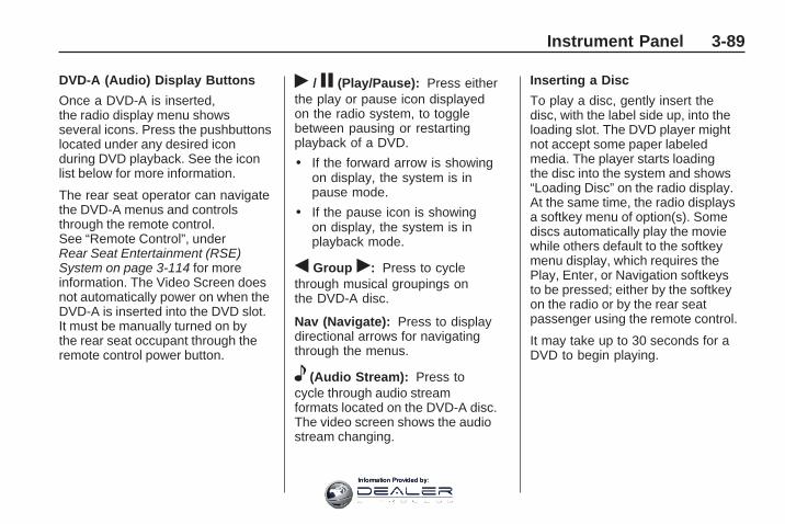
DVD-A (Audio) Display Buttons
Once a DVD-A is inserted,the radio display menu showsseveral icons. Press the pushbuttonslocated under any desired iconduring DVD playback. See the iconlist below for more information.
The rear seat operator can navigatethe DVD-A menus and controlsthrough the remote control.See “Remote Control”, underRear Seat Entertainment (RSE)System on page 3-114 for moreinformation. The Video Screen doesnot automatically power on when theDVD-A is inserted into the DVD slot.It must be manually turned on bythe rear seat occupant through theremote control power button.
r / j (Play/Pause): Press eitherthe play or pause icon displayedon the radio system, to togglebetween pausing or restartingplayback of a DVD.
• If the forward arrow is showingon display, the system is inpause mode.
• If the pause icon is showingon display, the system is inplayback mode.
q Group r: Press to cyclethrough musical groupings onthe DVD-A disc.
Nav (Navigate): Press to displaydirectional arrows for navigatingthrough the menus.
e (Audio Stream): Press tocycle through audio streamformats located on the DVD-A disc.The video screen shows the audiostream changing.
Inserting a Disc
To play a disc, gently insert thedisc, with the label side up, into theloading slot. The DVD player mightnot accept some paper labeledmedia. The player starts loadingthe disc into the system and shows“Loading Disc” on the radio display.At the same time, the radio displaysa softkey menu of option(s). Somediscs automatically play the moviewhile others default to the softkeymenu display, which requires thePlay, Enter, or Navigation softkeysto be pressed; either by the softkeyon the radio or by the rear seatpassenger using the remote control.
It may take up to 30 seconds for aDVD to begin playing.
Instrument Panel 3-89
Information Provided by:

Stopping and Resuming Playback
To stop playing a DVD withoutturning off the system, do one ofthe following:
• Press c on the remote control.
• Press the pushbutton locatedunder the stop or the play/pauseicons displayed on the radio.
• If the radio head is sourced tosomething other than DVD-V,press the DVD/CD AUX button tomake DVD-V the active source.
To resume DVD playback, do oneof the following:
• Press r / j on the remotecontrol.
• Press the pushbutton locatedunder the play/pause icondisplayed on the radio.
The DVD should resume play fromwhere it last stopped if the disc hasnot been ejected and the stop button
has not been pressed twice on theremote control. If the disc has beenejected or the stop button has beenpressed twice on the remote control,the disc resumes playing at thebeginning of the disc.
Ejecting a Disc
Press Z DVD on the radio toeject the disc. If a disc is ejectedfrom the radio, but not removed,the radio reloads the disc after ashort period of time. The disc isstored in the radio. The radiodoes not resume play of the discautomatically. If the movie isreloaded and the RSA system issourced to the DVD, the playerbegins to play again. If loading andreading a DVD or CD cannot becompleted, and the disc fails to eject,press and hold Z DVD for morethan five seconds to force the discto eject.
DVD Radio Error Messages
Player Error: This messagedisplays when there are disc loador eject problems.
Disc Format Error: This messagedisplays, if the disc is inserted withthe disc label wrong side up, or if thedisc is damaged.
Disc Region Error: This messagedisplays, if the disc is not from acorrect region.
No Disc Inserted: This messagedisplays, if no disc is presentwhen Z DVD or DVD/CD AUXis pressed on the radio.
3-90 Instrument Panel
Information Provided by:

Using the Auxiliary Input JackThe radio system has an auxiliaryinput jack located on the lowerright side of the faceplate. This isnot an audio output; do not plug aheadphone set into the front auxiliaryinput jack. Connect an auxiliary inputdevice such as an iPod, laptopcomputer, MP3 player, CD player,or cassette tape player, etc. to theauxiliary input jack for use as anothersource for audio listening.
Drivers are encouraged to set upany auxiliary device while the vehicleis in P (Park). See Defensive Drivingon page 4-2 for more information ondriver distraction.
To use an auxiliary input device,connect a 3.5 mm (1/8 inch) cable tothe radio’s front auxiliary input jack.
O (Power/Volume): Turn clockwiseor counterclockwise to increaseor decrease the volume of theportable player. Additional volumeadjustments might have to be madefrom the portable device if thevolume is not loud or soft enough.
BAND: Press to listen to the radiowhen a portable audio device isplaying. The portable audio devicecontinues playing, so you mightwant to stop it or turn it off.
CD/AUX (CD/Auxiliary): Press toselect between CD, or Auxiliary.
• When a CD is in the playerthe CD icon and a messageshowing the disc and/or tracknumber displays.
• If an auxiliary input device is notconnected, “No Input DeviceFound” displays.
DVD/CD AUX (Auxiliary): Pressto select between DVD, CD, orAuxiliary.
• If an auxiliary input device is notconnected, “No Aux Input Device”displays.
• When a disc is in either slot,the DVD/CD text label and amessage showing the track orchapter number displays.
• If an auxiliary input device is notconnected, and a disc is in boththe DVD slot and the CD slot theDVD/CD AUX button only cyclesbetween the two sources anddoes not indicate “No Aux InputDevice”.
• If a front auxiliary input device isconnected, the DVD/CD AUXbutton cycles through all availableoptions.
Instrument Panel 3-91
Information Provided by:

If a disc is inserted into top DVDslot, the rear seat operator canturn on the video screen and usethe remote control to only navigatethe CD tracks through the remotecontrol.
See “Using the Auxiliary InputJack(s)” later in this section, or“Audio/Video (A/V) Jacks” under,Rear Seat Entertainment (RSE)System on page 3-114 for moreinformation.
Using an MP3(Radio with CD)MP3/WMA CD-R orCD-RW DiscThe radio plays MP3/WMA files thatwere recorded on a CD-R or CD-RWdisc. The files can be recorded withthe following fixed bit rates: 32 kbps,40 kbps, 56 kbps, 64 kbps, 80 kbps,96 kbps, 112 kbps, 128 kbps,160 kbps, 192 kbps, 224 kbps,256 kbps, and 320 kbps or a variablebit rate. Song title, artist name, andalbum are available for display by theradio when recorded using ID3 tagsversion 1 and 2.
Compressed Audio
The radio also plays discs thatcontain both uncompressed CDaudio (.CDA files) and MP3/WMAfiles. The radio plays both file formatsin the order in which they wererecorded to the disc.
MP3/WMA Format
Creating an MP3/WMA disc on apersonal computer:
• Make sure the MP3/WMA filesare recorded on a CD-R orCD-RW disc.
• Do not mix standard audio andMP3/WMA files on one disc.
3-92 Instrument Panel
Information Provided by:

• The CD player is able toread and play a maximum of50 folders, 15 playlists, and acombined total of 512 foldersand files.
• Create a folder structure thatmakes it easy to find songswhile driving. Organize songsby albums using one folder foreach album. Each folder or albumshould contain 18 songs or less.
• Avoid subfolders. The systemcan support up to eight subfoldersdeep, however, keep the totalnumber of folders to a minimumin order to reduce the complexityand confusion in trying to locate aparticular folder during playback.
• Make sure playlists have a .mp3or .wpl extension (other fileextensions might not work).
• Minimize the length of the file,folder, or playlist names. Long file,folder, or playlist names, or acombination of a large numberof files and folders, or playlistscould cause the player to beunable to play up to the maximumnumber of files, folders, playlists,or sessions. To play a largenumber of files, folders, playlistsor sessions, minimize the lengthof the file, folder, or playlist name.Long names also take up morespace on the display, potentiallygetting cut off.
• Finalize the audio disc beforeburning it. Trying to add music toan existing disc could cause thedisc not to function in the player.
Change playlists by using Sc andcT folder buttons, the f knob,or the SEEK arrows. An MP3/WMACD-R or CD-RW that was recordedusing no file folders can be played.
If a CD-R or CD-RW contains morethan the maximum of 50 folders,15 playlists, and a combined total of512 folders and files, the playeraccesses and navigates up to themaximum, but all items over themaximum are not accessible.
Root Directory
The root directory of the CD-R orCD-RW is treated as a folder. If theroot directory has compressed audiofiles, the directory displays as theCD label. All files contained directlyunder the root directory areaccessed prior to any root directoryfolders. However, playlists (Px) arealways accessed before root foldersor files.
If a disc contains bothuncompressed CD audio (.CDA)and MP3/WMA files, a folder underthe root directory called CD accessesall of the CD audio tracks on the disc.
Instrument Panel 3-93
Information Provided by:

Empty Directory or Folder
If a root directory or a folder existssomewhere in the file structure thatcontains only folders/subfolders andno compressed files directly beneaththem, the player advances to thenext folder in the file structure thatcontains compressed audio files.The empty folder does not display.
No Folder
When the CD-R or CD-RW disccontains only compressed files,the files are located under the rootfolder. The next and previous folderfunction does not display on a CD-Ror CD-RW disc that was recordedwithout folders or playlists.
When the CD-R or CD-RWdisc contains only playlists andcompressed audio files, but nofolders, all files are located underthe root folder. The folder down andup buttons search playlists (Px) firstand then goes to the root folder.
Order of Play
Tracks recorded to the CD-R orCD-RW disc are played in thefollowing order:
• Play begins from the first trackin the first playlist and continuessequentially through all tracks ineach playlist. When the last trackof the last playlist has played, playcontinues from the first track ofthe first playlist.
• Play begins from the first trackin the first folder and continuessequentially through all tracks ineach folder. When the last track ofthe last folder has played, playcontinues from the first track ofthe first folder.
When play enters a new folder,the display does not automaticallyshow the new folder name unlessthe folder mode is chosen as thedefault display. The new track namedisplays.
File System and Naming
The song name that displays is thesong name that is contained in theID3 tag. If the song name is notpresent in the ID3 tag, then the radiodisplays the file name without theextension (such as .mp3) as thetrack name.
Track names longer than32 characters or four pagesare shortened. Parts of wordson the last page of text and theextension of the filename doesnot display.
Preprogrammed Playlists
Preprogrammed playlists thatwere created using WinAmp™,MusicMatch™, or Real Jukebox™software can be accessed, however,they cannot be edited using theradio. These playlists are treatedas special folders containingcompressed audio song files.
3-94 Instrument Panel
Information Provided by:

Playing an MP3/WMA
Insert a CD-R or CD-RW discpartway into the slot label side up.The player pulls it in, and the CD-Ror CD-RW should begin playing.
Z EJECT: Press to eject the disc.
f (Tune): Turn to select MP3/WMAfiles on the CD-R or CD-RWcurrently playing.
©SEEK ¨: Press the leftSEEK arrow to go to the start of thecurrent MP3/WMA file, if more thanten seconds have played. Press theright SEEK arrow to go to the nextMP3/WMA file. If either SEEK arrowis held or pressed multiple times, theplayer continues moving backward orforward through MP3/WMA files onthe CD.
Sc (Previous Folder): Pressthe pushbutton positioned underthe Folder label to go to thefirst track in the previous folder.
cT (Next Folder): Pressthe pushbutton positioned underthe Folder label to go to thefirst track in the next folder.
s REV (Reverse): Press andhold this button to reverse playbackquickly within an MP3/WMA file.Sound is heard at a reduced volume.Release this button to resumeplaying the file. The elapsed timeof the file displays.
\ FWD (Fast Forward): Pressand hold this button to advanceplayback quickly within anMP3/WMA file. Sound is heardat a reduced volume. Release thisbutton to resume playing the file.The elapsed time of the file displays.
RDM (Random): With the randomsetting, MP3/WMA files on theCD-R or CD-RW can be listened toin random, rather than sequentialorder.
To play MP3/WMA files from theCD-R or CD-RW in random order,press the pushbutton positionedunder the RDM label until RandomCurrent Disc displays. Press thesame pushbutton again to turn offrandom play.
Instrument Panel 3-95
Information Provided by:

h (Music Navigator): Usethe music navigator feature to playMP3/WMA files on the CD-R orCD-RW in order by artist or album.Press the pushbutton located belowthe music navigator label. The playerscans the disc to sort the files byartist and album ID3 tag information.It could take several minutes to scanthe disc depending on the numberof MP3/WMA files recorded to theCD-R or CD-RW disc. The radio canbegin playing while it is scanning thedisc in the background. When thescan is finished, the CD-R orCD-RW begins playing again.
Once the disc has scanned, theplayer defaults to playing MP3/WMAfiles in order by artist. The currentartist playing is shown on the secondline of the display between thearrows. Once all songs by that artistare played, the player moves to thenext artist in alphabetical order onthe CD-R or CD-RW and beginsplaying MP3/WMA files by that artist.To listen to MP3/WMA files byanother artist, press the pushbutton
located below either arrow button.The player goes to the next orprevious artist in alphabetical order.Continue pressing either button untilthe desired artist is displayed.
To change from playback by artistto playback by album, press thepushbutton located below the SortBy label. From the sort screen, pushone of the buttons below the albumbutton. Press the pushbutton belowthe back label to return to the mainmusic navigator screen. Now thealbum name is displayed on thesecond line between the arrows andsongs from the current album beginsto play. Once all songs from thatalbum are played, the player movesto the next album in alphabeticalorder on the CD-R or CD-RW andbegins playing MP3/WMA files fromthat album.
To exit music navigator mode, pressthe pushbutton below the Back labelto return to normal MP3/WMAplayback.
Using an MP3 (Radiowith CD and DVD Player)MP3/WMA CD-R orCD-RW Disc
Compressed Audio or MixedMode Discs
The radio also plays discs thatcontain both uncompressed CDaudio (.CDA files) and MP3/WMAfiles depending on which slot the discis loaded into. By default the radioreads only the uncompressed audio(.CDA) and ignores the MP3/WMAfiles on the DVD deck. On the CDdeck, pressing the CAT (category)button toggles between compressedand uncompressed audio format,the default being the uncompressedformat (.CDA).
3-96 Instrument Panel
Information Provided by:

MP3/WMA Format
To create an MP3/WMA disc on apersonal computer:• Make sure the MP3/WMA files
are recorded on a CD-R orCD-RW disc.
• Do not mix standard audio andMP3/WMA files on one disc.
• The CD player (lower slot) isable to read and play a maximumcombination of 512 files andfolders. The DVD player (upperslot) is able to read 255 folders,15 playlists and 40 sessions.
• Create a folder structure thatmakes it easy to find songswhile driving. Organize songs byalbums using one folder for eachalbum. Each folder or albumshould contain 18 songs or less.
• Avoid subfolders. The system cansupport up to eight subfoldersdeep, however, keep the totalnumber of folders to a minimumin order to reduce the complexityand confusion in trying to locate aparticular folder during playback.
• Make sure playlists havea .m3u, .wpl or .pls extensionas other file extensions mightnot work.
• Minimize the length of the file,folder or playlist names. Long file,folder, or playlist names, or acombination of a large number offiles and folders, or playlists couldcause the player to be unable toplay up to the maximum numberof files, folders, playlists, orsessions. To play a large numberof files, folders, playlists, orsessions, minimize the length ofthe file, folder, or playlist name.Long names also take up morespace on the display, potentiallygetting cut off.
• Finalize the audio disc beforeburning it. Trying to add music toan existing disc could cause thedisc not to function in the player.
Root Directory
The root directory of the CD-R orCD-RW disc is treated as a folder.If the root directory has compressedaudio files, the directory is displayedas F1 ROOT. All files containeddirectly under the root directory areaccessed prior to any root directoryfolders. However, playlists (Px) arealways accessed before root foldersor files.
Empty Directory or Folder
If a root directory or a folder existssomewhere in the file structure thatcontains only folders/subfolders andno compressed files directly beneaththem, the player advances to thenext folder in the file structure thatcontains compressed audio files.The empty folder does not display.
Instrument Panel 3-97
Information Provided by:

No Folder
When the CD-R or CD-RW disccontains only compressed files,the files are located under theroot folder. The next and previousfolder function does not functionon a CD-R or CD-RW that wasrecorded without folders or playlists.When displaying the name of thefolder the radio displays ROOT.
When the CD-R or CD-RWdisc contains only playlists andcompressed audio files, but nofolders, all files are located underthe root folder. The folder downand the folder up buttons searchplaylists (Px) first and then goesto the root folder. When the radiodisplays the name of the folder theradio displays ROOT.
Order of Play
Tracks recorded to the CD-R orCD-RW disc are played in thefollowing order:
• Play begins from the first trackin the first playlist and continuessequentially through all tracks ineach playlist. When the last trackof the last playlist has played, playcontinues from the first track ofthe first playlist.
• Play begins from the first trackin the first folder and continuessequentially through all tracks ineach folder. When the last trackof the last folder has played, playcontinues from the first track ofthe first folder.
When play enters a new folder,the display does not automaticallyshow the new folder name unless thefolder mode has been chosen as thedefault display. The new track namedisplays.
File System and Naming
The song name that is displayed isthe song name that is contained inthe ID3 tag. If the song name is notpresent in the ID3 tag, then the radiodisplays the file name without theextension (such as .mp3) as thetrack name.
Track names longer than32 characters or four pagesare shortened. Parts of wordson the last page of text and theextension of the filename displays.
Preprogrammed Playlists
Preprogrammed playlists thatwere created using WinAmp™,MusicMatch™, or Real Jukebox™software can be accessed, however,they cannot be edited using theradio. These playlists are treatedas special folders containingcompressed audio song files.
3-98 Instrument Panel
Information Provided by:

Playing an MP3/WMA(In Either the DVD or CD Slot)
Insert a CD-R or CD-RW discpartway into either the top or bottomslot, label side up. The player pulls itin, and the CD-R or CD-RW shouldbegin playing.
Depending on the format of thedisc, a softkey menu appears andallows navigation of the disc.The menu reads left to right asRDM (Randomize song play order),a Folder icon with left and rightarrows (to move up or down throughavailable folders), a PL tag if the dischas a Playlist available, and a MusicNavigator tag. If a Playlist tag isshown, toggling this key brings upa Folder softkey only or the menuas previously described.
If the ignition or radio is turned offwith a CD-R or CD-RW disc in theplayer it stays in the player. Whenthe ignition or radio is turned back
on, the CD-R or CD-RW starts toplay where it stopped, if it was thelast selected audio source.
As each new track starts to play,the track number and song titledisplays.
Z CD (Eject): Press and releasethis button to eject the CD-R orCD-RW that is currently playing inthe bottom slot. A beep sounds andEjecting Disc displays. Once the discis ejected, Remove Disc displays.The CD-R or CD-RW disc can beremoved. If the CD-R or CD-RWdisc is not removed, afterseveral seconds, the CD-R orCD-RW disc automatically pullsback into the player.
If loading and reading of a CD cannotbe completed, such as unknownformat, etc., and the disc fails toeject, press and hold this button formore than five seconds to force thedisc to eject.
Z DVD (Eject): Press and releasethis button to eject the CD-R orCD-RW that is currently playing inthe top slot. A beep sounds andEjecting Disc displays. Once thedisc is ejected, Remove Discdisplays. The CD-R or CD-RW disccan be removed. If the CD-R orCD-RW disc is not removed, afterseveral seconds, the CD-R orCD-RW disc automatically pulls backinto the player. If loading and readingof a CD cannot be completed, suchas unknown format, etc., and the discfails to eject, press and hold thisbutton for more than five secondsto force the disc to eject.
f (Tune): Turn this knob to selectMP3/WMA files on the CD-R orCD-RW that is currently playing.
Instrument Panel 3-99
Information Provided by:

©SEEK ¨: Press the leftSEEK arrow to go to the start ofthe current MP3/WMA file, if morethan five seconds have played.If less than five seconds haveplayed, the previous MP3/WMA fileplays. Press the right SEEK arrowto go to the next MP3/WMA file.If either SEEK arrow is held, orpressed multiple times, the playercontinues moving backward orforward through the MP3/WMAfiles on the CD.
Sc (Previous Folder): Pressthe pushbutton positioned underthe Folder label to go to thefirst track in the previous folder.
cT (Next Folder): Pressthe pushbutton positioned underthe Folder label to go to thefirst track in the next folder.
s REV (Reverse): Press andhold this button to reverse playbackquickly within an MP3/WMA file.Sound is heard at a reduced volume.Release this button to resumeplaying the file. The elapsed timeof the file displays.
\ FWD (Fast Forward): Pressand hold this button to advanceplayback quickly within an MP3/WMA file. Sound is heard at areduced volume. Release thisbutton to resume playing the file.The elapsed time of the file displays.
RDM (Random): With the randomsetting, MP3/WMA files on the CD-Ror CD-RW can be listened to inrandom, rather than sequential order.To play MP3/WMA files from theCD-R or CD-RW in random order,press the pushbutton positionedunder the RDM label until RandomCurrent Disc displays. Press thesame pushbutton again to turn offrandom play.
h (Music Navigator): Use themusic navigator feature to playMP3/WMA files on the CD-R orCD-RW in order by artist or album.Press the pushbutton located belowthe music navigator label. The playerscans the disc to sort the files byartist and album ID3 tag information.It could take several minutes to scanthe disc depending on the numberof MP3/WMA files recorded to theCD-R or CD-RW disc.
To cancel music navigator whilethe player is scanning, press thepushbutton located below the musicnavigator label or eject the disc.
The radio can begin playing while it isscanning the disc in the background.When the scan is finished, the CD-Ror CD-RW begins playing again.
3-100 Instrument Panel
Information Provided by:

Once the disc has been scanned,the player defaults to playingMP3/WMA files in order by artist.The current artist playing is shownon the second line of the displaybetween the arrows. To listen toMP3/WMA files by another artist,press the pushbutton located beloweither arrow button. The disc goesto the next or previous artist inalphabetical order. Continuepressing either button until thedesired artist is displayed.
To change from playback by artistto playback by album, press thepushbutton located below the SortBy label. From the sort screen, pushone of the buttons below the albumbutton. Press the pushbutton belowthe back label to return to the mainmusic navigator screen. Now thealbum name displays on the secondline between the arrows and songsfrom the current album begin to play.
Once all songs from that album areplayed, the player moves to the nextalbum in alphabetical order on theCD-R or CD-RW and begins playingMP3/WMA files from that album.
To exit music navigator mode, pressthe pushbutton below the Back labelto return to normal MP3/WMAplayback.
BAND: Press this button to listen tothe radio when a CD or a DVD isplaying. The CD or DVD remainsinside the radio for future listeningor viewing entertainment.
DVD/CD AUX (Auxiliary): Pressthis button to cycle through DVD,CD, or Auxiliary when listening to theradio. The DVD/CD text label and amessage showing track or chapternumber displays when a disc is ineither slot. Press this button againand the system automaticallysearches for an auxiliary input
device, such as a portable audioplayer. If a portable audio playeris not connected, “No Aux InputDevice” displays. If a disc is in boththe DVD slot and the CD slot theDVD/CD AUX button cycles betweenthe two sources and does notindicate “No Aux Input Device”.If a front auxiliary device isconnected, the DVD/CD AUXbutton cycles through all availableoptions, such as: DVD slot, CD slot,Front Auxiliary, and Rear Auxiliary(if available). See “Using theAuxiliary Input Jack(s)” later in thissection, or “Audio/Video (A/V) Jacks”under, Rear Seat Entertainment(RSE) System on page 3-114 formore information.
If a MP3/WMA is inserted into topDVD slot, the rear seat operator canturn on the video screen and use theremote control to navigate the CD(tracks only).
Instrument Panel 3-101
Information Provided by:

XM Radio MessagesXL (Explicit Language Channels):These channels, or any others, canbe blocked at a customer’s request,by calling 1-800-852-XMXM (9696).
XM Updating: The encryptioncode in the receiver is beingupdated, and no action is required.This process should take no longerthan 30 seconds.
No XM Signal: The system isfunctioning correctly, but the vehicleis in a location that is blockingthe XM™ signal. When the vehicleis moved into an open area, thesignal should return.
Loading XM: The audio systemis acquiring and processing audioand text data. No action is needed.This message should disappearshortly.
Channel Off Air: This channelis not currently in service. Tunein to another channel.
Channel Unauth: This channelis blocked or cannot be receivedwith your XM Subscription package.
Channel Unavail: This previouslyassigned channel is no longerassigned. Tune to another station.If this station was one of the presets,choose another station for thatpreset button.
No Artist Info: No artist informationis available at this time on thischannel. The system is workingproperly.
No Title Info: No song titleinformation is available at thistime on this channel. The systemis working properly.
No CAT Info: No categoryinformation is available at thistime on this channel. The systemis working properly.
No Information: No text orinformational messages areavailable at this time on thischannel. The system is workingproperly.
CAT Not Found: There are nochannels available for the selectedcategory. The system is workingproperly.
XM Theftlocked: The XM receiverin the vehicle could have previouslybeen in another vehicle. For securitypurposes, XM receivers cannot beswapped between vehicles. If thismessage is received after having thevehicle serviced, check with yourdealer/retailer.
XM Radio ID: If tuned to channel 0,this message alternates with theXM™ Radio 8 digit radio ID label.This label is needed to activate theservice.
3-102 Instrument Panel
Information Provided by:

Unknown: If this message isreceived when tuned to channel 0,there could be a receiver fault.Consult with your dealer/retailer.
Check XM Receivr: If thismessage does not clear within ashort period of time, the receivercould have a fault. Consult withyour dealer/retailer.
XM Not Available: If this messagedoes not clear within a short period oftime, the receiver could have a fault.Consult with your dealer/retailer.
Navigation/Radio SystemFor vehicles with a navigationradio system, see the separateNavigation System manual.
Bluetooth®
Vehicles with a Bluetooth systemcan use a Bluetooth capable cellphone with a Hands Free Profileto make and receive phone calls.The system can be used whilethe key is in ON/RUN or ACC/ACCESSORY position. The rangeof the Bluetooth system can be upto 30 ft. (9.1 m). Not all phonessupport all functions, and not allphones are guaranteed to workwith the in-vehicle Bluetooth system.See gm.com/bluetooth for moreinformation on compatible phones.
Voice RecognitionThe Bluetooth system uses voicerecognition to interpret voicecommands to dial phone numbersand name tags.
Noise: Keep interior noise levels toa minimum. The system may notrecognize voice commands if thereis too much background noise.
When to Speak: A short tonesounds after the system respondsindicating when it is waiting fora voice command. Wait untilthe tone and then speak.
How to Speak: Speak clearly in acalm and natural voice.
Audio SystemWhen using the in-vehicle Bluetoothsystem, sound comes throughthe vehicle’s front audio systemspeakers and overrides the audiosystem. Use the audio systemvolume knob, during a call, to changethe volume level. The adjustedvolume level remains in memory forlater calls. To prevent missed calls,a minimum volume level is used if thevolume is turned down too low.
Instrument Panel 3-103
Information Provided by:

Bluetooth ControlsUse the buttons located on thesteering wheel to operate thein-vehicle Bluetooth system.See Audio Steering Wheel Controlson page 3-125 for more information.
bg (Push To Talk): Press toanswer incoming calls, to confirmsystem information, and to startspeech recognition.
cx (Phone On Hook): Press toend a call, reject a call, or to cancelan operation.
PairingA Bluetooth enabled cell phone mustbe paired to the in-vehicle Bluetoothsystem first and then connected tothe vehicle before it can be used.See the cell phone manufacturersuser guide for Bluetooth functionsbefore pairing the cell phone. If aBluetooth phone is not connected,calls will be made using OnStar®
Hands-Free Calling, if available.Refer to the OnStar owner’s guidefor more information.
Pairing Information:
• Up to five cell phones canbe paired to the in-vehicleBluetooth system.
• The pairing process is disabledwhen the vehicle is moving.
• The in-vehicle Bluetooth systemautomatically links with the firstavailable paired cell phone in theorder the phone was paired.
• Only one paired cell phone canbe connected to the in-vehicleBluetooth system at a time.
• Pairing should only need to becompleted once, unless changesto the pairing information havebeen made or the phone isdeleted.
To link to a different paired phone,see Linking to a Different Phonelater in this section.
Pairing a Phone
1. Press and hold b g fortwo seconds. The systemresponds with “Ready” followedby a tone.
2. Say “Bluetooth”. The systemresponds with “Bluetoothready” followed by a tone.
3. Say “Pair”. The system respondswith instructions and a four digitPIN number. The PIN numberwill be used in Step 4.
4. Start the Pairing process on thecell phone that will be paired tothe vehicle. Reference the cellphone manufacturers user guidefor information on this process.Locate the device named“General Motors” in the list onthe cellular phone and follow theinstructions on the cell phoneto enter the four digit PIN numberthat was provided in Step 3.
3-104 Instrument Panel
Information Provided by:

5. The system prompts for a namefor the phone. Use a name thatbest describes the phone. Thisname will be used to indicatewhich phone is connected. Thesystem then confirms the nameprovided.
6. The system responds with“<Phone name> has beensuccessfully paired” after thepairing process is complete.
7. Repeat Steps 1 through 7 foradditional phones to be paired.
Listing All Paired and ConnectedPhones
1. Press and hold b g fortwo seconds. The systemresponds with “Ready” followedby a tone.
2. Say “Bluetooth”. The systemresponds with “Bluetoothready” followed by a tone.
3. Say “List”. The system lists allthe paired Bluetooth devices.If a phone is connected to
the vehicle, the system willsay “Is connected” after theconnected phone.
Deleting a Paired Phone
1. Press and hold b g fortwo seconds. The systemresponds with “Ready” followedby a tone.
2. Say “Bluetooth”. The systemresponds with “Bluetoothready” followed by a tone.
3. Say “Delete”. The system askswhich phone to delete followedby a tone.
4. Say the name of the phone tobe deleted. If the phone name isunknown, use the “List” commandfor a list of all paired phones.The system responds with “Wouldyou like to delete <phone name>?Yes or No” followed by a tone.
5. Say “Yes” to delete the phone.The system responds with“OK, deleting <phone name>”.
Linking to a Different Phone
1. Press and hold b g fortwo seconds. The systemresponds with “Ready” followedby a tone.
2. Say “Bluetooth”. The systemresponds with “Bluetoothready” followed by a tone.
3. Say “Change phone”.The system responds with“Please wait while I searchfor other phones”.
• If another phone is found,the response will be “<Phonename> is now connected”.
• If another phone is not found,the original phone remainsconnected.
Instrument Panel 3-105
Information Provided by:

Storing Name TagsThe system can store up to thirtyphone numbers as name tagsthat are shared between theBluetooth and OnStar systems.
The system uses the followingcommands to store and retrievephone numbers:
• Store
• Digit Store
• Directory
Using the Store Command
The store command allows a phonenumber to be stored without enteringthe digits individually.
1. Press and hold b g fortwo seconds. The systemresponds with “Ready” followedby a tone.
2. Say “Store”. The systemresponds with “Store, numberplease” followed by a tone.
3. Say the complete phone numberto be stored at once with nopauses.
• If the system recognizesthe number it responds with“OK, Storing” and repeats thephone number.
• If the system is unsure itrecognizes the phone number,it responds with “Store” andrepeats the number followedby “Please say yes or no”.If the number is correct, say“Yes”. If the number is notcorrect, say “No”. The systemwill ask for the number to bere-entered.
4. After the system stores thephone number, it respondswith “Please say the name tag”followed by a tone.
5. Say a name tag for thephone number. The nametag is recorded and the systemresponds with “About to store<name tag>. Does thatsound OK?”.
• If the name tag does not soundcorrect, say “No” and repeatStep 5.
• If the name tag soundscorrect, say “Yes” and thename tag is stored. After thenumber is stored the systemreturns to the main menu.
3-106 Instrument Panel
Information Provided by:

Using the Digit Store Command
The digit store command allowsa phone number to be storedby entering the digits individually.
1. Press and hold b g fortwo seconds. The systemresponds with “Ready” followedby a tone.
2. Say “Digit Store”. The systemresponds with “Please say thefirst digit to store” followedby a tone.
3. Say the first digit to be stored.The system will repeat backthe digit it heard followed by atone. Continue entering digitsuntil the number to be storedis complete.
• If an unwanted number isrecognized by the system,say “Clear” at any timeto clear the last number.
• To hear all of the numbersrecognized by the system, say“Verify” at any time and thesystem will repeat them.
4. After the complete numberhas been entered, say “Store”.The system responds with“Please say the name tag”followed by a tone.
5. Say a name tag for thephone number. The nametag is recorded and thesystem responds with“About to store <name tag>.Does that sound OK?”.
• If the name tag does notsound correct, say “No”and repeat Step 5.
• If the name tag soundscorrect, say “Yes” andthe name tag is stored.After the number is storedthe system returns to themain menu.
Using the Directory Command
The directory command listsall of the name tags stored bythe system. To use the directorycommand:
1. Press and hold b g fortwo seconds. The systemresponds with “Ready” followedby a tone.
2. Say “Directory”. The systemresponds with “Directory”and then plays back all of thestored name tags. When thelist is complete, the systemreturns to the main menu.
Deleting Name TagsThe system uses the followingcommands to delete name tags:
• Delete
• Delete all name tags
Instrument Panel 3-107
Information Provided by:

Using the Delete Command
The delete command allows specificname tags to be deleted.
To use the delete command:
1. Press and hold b g fortwo seconds. The systemresponds with “Ready” followedby a tone.
2. Say “Delete”. The systemresponds with “Delete, pleasesay the name tag” followed bya tone.
3. Say the name tag to be deleted.The system responds with “Wouldyou like to delete, <name tag>?Please say yes or no”.• If the name tag is correct, say
“Yes” to delete the name tag.The system responds with“OK, deleting <name tag>,returning to the main menu.”
• If the name tag is incorrect,say “No”. The systemresponds with “No. OK,let’s try again, please saythe name tag.”
Using the Delete All Name TagsCommand
The delete all name tags commanddeletes all stored phone book nametags and route name tags for OnStar(if present).
To use the delete all name tagscommand:
1. Press and hold b g fortwo seconds. The systemresponds with “Ready” followedby a tone.
2. Say “Delete all name tags”.The system responds with“You are about to delete allname tags stored in yourphone directory and yourroute destination directory.Are you sure you want to dothis? Please say yes or no.”
• Say “Yes” to delete allname tags.
• Say “No” to cancel thefunction and return tothe main menu.
Making a CallCalls can be made using thefollowing commands:
• Dial
• Digit Dial
• Call
• Re-dial
Using the Dial Command
1. Press and hold b g fortwo seconds. The systemresponds with “Ready” followedby a tone.
2. Say “Dial”. The system respondswith “Dial using <phone name>.“Number please” followed bya tone.
3-108 Instrument Panel
Information Provided by:

3. Say the entire number withoutpausing.
• If the system recognizes thenumber, it responds with“OK, Dialing” and dialsthe number.
• If the system does notrecognize the number, itconfirms the numbers followedby a tone. If the number iscorrect, say “Yes”. The systemresponds with “OK, Dialing”and dials the number. If thenumber is not correct, say“No”. The system will ask forthe number to be re-entered.
Using the Digit Dial Command
1. Press and hold b g fortwo seconds. The systemresponds with “Ready” followedby a tone.
2. Say “Digit Dial”. The systemresponds with “Digit dial using<phone name>, please say thefirst digit to dial” followed bya tone.
3. Say the digit to be dialed oneat a time. Following eachdigit, the system will repeatback the digit it heard followedby a tone.
4. Continue entering digits until thenumber to be dialed is complete.After the whole number has beenentered, say “Dial”. The systemresponds with “OK, Dialing” anddials the number.
• If an unwanted number isrecognized by the system,say “Clear” at any time toclear the last number.
• To hear all of the numbersrecognized by the system, say“Verify” at any time and thesystem will repeat them.
Instrument Panel 3-109
Information Provided by:

Using the Call Command
1. Press and hold b g fortwo seconds. The systemresponds with “Ready” followedby a tone.
2. Say “Call”. The system respondswith “Call using <phone name>.Please say the name tag”followed by a tone.
3. Say the name tag of the personto call.
• If the system clearlyrecognizes the name tag itresponds with “OK, calling,<name tag>” and dials thenumber.
• If the system is unsure itrecognizes the right nametag, it confirms the name tagfollowed by a tone. If the nametag is correct, say “Yes”.
The system responds with“OK, calling, <name tag>” anddials the number. If the nametag is not correct, say “No”.The system will ask for thename tag to be re-entered.
Once connected, the person calledwill be heard through the audiospeakers.
Using the Re-dial Command
1. Press and hold b g fortwo seconds. The systemresponds with “Ready” followedby a tone.
2. After the tone, say “Re-dial”.The system responds with“Re-dial using <phone name>”and dials the last numbercalled from the connectedBluetooth phone.
Once connected, the person calledwill be heard through the audiospeakers.
Receiving a CallWhen an incoming call is received,the audio system mutes and aring tone is heard in the vehicle.
• Press b g and begin speakingto answer the call.
• Press cx to ignore a call.
Call WaitingCall waiting must be supported onthe Bluetooth phone and enabled bythe wireless service carrier to work.
• Press bg to answer anincoming call when another call isactive. The original call is placedon hold.
• Press bg again to return to theoriginal call.
• To ignore the incoming call,continue with the original call withno action.
• Press cx to disconnect thecurrent call and switch to the callon hold.
3-110 Instrument Panel
Information Provided by:

Three-Way CallingThree-Way Calling must besupported on the Bluetoothphone and enabled by thewireless service carrier to work.
1. While on a call press b g.The system responds with“Ready” followed by a tone.
2. Say “Three-way call”. The systemresponds with “Three-way call,please say dial or call”.
3. Use the dial or call command todial the number of the third partyto be called.
4. Once the call is connected,press b g to link all the callerstogether.
Ending a Call
Press cx to end a call.
Muting a CallDuring a call, all sounds from insidethe vehicle can be muted so thatthe person on the other end ofthe call cannot hear them.
To Mute a call
1. Press b g. The systemresponds with “Ready” followedby a tone.
2. Say “Mute Call”. The systemresponds with “Call muted”.
To Cancel Mute
1. Press b g. The systemresponds with “Ready” followedby a tone.
2. After the tone, say “Mute Call”.The system responds with“Resuming call”.
Transferring a CallAudio can be transferred betweenthe in-vehicle Bluetooth systemand the cell phone.
To Transfer Audio to the CellPhone
During a call with the audio in thevehicle:
1. Press b g. The systemresponds with “Ready” followedby a tone.
2. Say “Transfer Call.” The systemresponds with “Transferring call”and the audio will switch fromthe vehicle to the cell phone.
To Transfer Audio to theIn-Vehicle Bluetooth System
The cellular phone must bepaired and connected with theBluetooth system before a call canbe transferred. The connectionprocess can take up to two minutesafter the key is turned to the ON/RUNor ACC/ACCESSORY position.
During a call with the audio on thecell phone, press bg for more thantwo seconds. The audio switchesfrom the cell phone to the vehicle.
Instrument Panel 3-111
Information Provided by:

Voice Pass-ThruVoice Pass-Thru allows access tothe voice recognition commands onthe cell phone. See the cell phonemanufacturers user guide to see ifthe cell phone supports this feature.This feature can be used to verballyaccess contacts stored in the cellphone.
1. Press and hold b g fortwo seconds. The systemresponds with “Ready” followedby a tone.
2. Say “Bluetooth”. The systemresponds with “Bluetoothready” followed by a tone.
3. Say “Voice”. The systemresponds with “OK, accessing<phone name>”.
• The cell phone’s normalprompt messages will gothrough its cycle accordingto the phone’s operatinginstructions.
Dual Tone Multi-Frequency(DTMF) TonesThe in-vehicle Bluetooth system cansend numbers and numbers storedas name tags during a call. This isused when calling a menu drivenphone system. Account numbers canbe programmed into the phonebookfor retrieval during menu driven calls.
Sending a Number During a Call
1. Press b g. The systemresponds with “Ready” followedby a tone.
2. Say “Dial”. The system respondswith “Say a number to sendtones” followed by a tone.
3. Say the number to send.
• If the system clearlyrecognizes the numberit responds with “OK, SendingNumber” and the dial tonesare sent and the callcontinues.
• If the system is not sure itrecognized the numberproperly, it responds “DialNumber, Please say yes orno?” followed by a tone. If thenumber is correct, say “Yes”.The system responds with“OK, Sending Number” andthe dial tones are sent andthe call continues.
3-112 Instrument Panel
Information Provided by:

Sending a Stored Name TagDuring a Call
1. Press b g. The systemresponds with “Ready” followedby a tone.
2. Say “Send name tag.”The system responds with“Say a name tag to send tones”followed by a tone.
3. Say the name tag to send.
• If the system clearlyrecognizes the name tagit responds with “OK,Sending <name tag>”and the dial tones aresent and the call continues.
• If the system is not sure itrecognized the name tagproperly, it responds “Dial<name tag>, Please say yesor no?” followed by a tone.If the name tag is correct, say“Yes”. The system respondswith “OK, Sending <nametag>” and the dial tones aresent and the call continues.
Clearing the SystemUnless information is deleted outof the in-vehicle Bluetooth system,it will be retained indefinitely.This includes all saved name tagsin the phonebook and phone pairinginformation. For information on howto delete this information, see theabove sections on Deleting a PairedPhone and Deleting Name Tags.
Other InformationThe Bluetooth® word mark andlogos are owned by the Bluetooth®
SIG, Inc. and any use of suchmarks by General Motors is underlicense. Other trademarks andtrade names are those of theirrespective owners.
This device complies with Part 15 ofthe FCC Rules. Operation is subjectto the following two conditions:
1. This device may not causeharmful interference.
2. This device must accept anyinterference received, includinginterference that may causeundesired operation.
This device complies with RSS-210of Industry Canada. Operation issubject to the following twoconditions:
1. This device may not causeinterference.
2. This device must accept anyinterference received, includinginterference that may causeundesired operation of thedevice.
Changes or modifications tothis system by other than anauthorized service facility could voidauthorization to use this equipment.
Instrument Panel 3-113
Information Provided by:

Rear Seat Entertainment(RSE) SystemThe vehicle may have a DVD RearSeat Entertainment (RSE) system.The RSE system works with thevehicle’s audio system. The DVDplayer is part of the front radio.The RSE system includes a radiowith a DVD player, a video displayscreen, audio/video jacks, twowireless headphones, and a remotecontrol. See Radio(s) on page 3-75for more information on the vehicle’saudio/DVD system.
Before DrivingThe RSE is designed for rear seatpassengers only. The driver cannotsafely view the video screen whiledriving and should not try to do so.
In severe or extreme weatherconditions the RSE system mightor might not work until thetemperature is within the operatingrange. The operating range for theRSE system is above −4°F (−20°C)or below 140°F (60°C). If thetemperature of the vehicle is outsideof this range, heat or cool the vehicleuntil the temperature is within theoperating range of the RSE system.
Parental ControlThe RSE system may have aParental Control feature, dependingon the radio. To enable ParentalControl, press and hold the radiopower button for more thantwo seconds to stop all systemfeatures such as: radio, videoscreen, RSA, DVD and/or CD.While Parental Control ison, Q displays.
When the radio is turned back on,Parental Control is unlocked.
Headphones
The RSE includes two 2-channelwireless headphones that arededicated to this system. Channel 1is dedicated to the video screen,while Channel 2 is dedicated to RSAselections. These headphones areused to listen to media such as CDs,DVDs, MP3/WMAs, DVD-As, radio,any auxiliary source connected toA/V jacks, or the auxiliary inputjack, if the vehicle has this feature.
3-114 Instrument Panel
Information Provided by:

The wireless headphones have anOn/Off button, channel 1/2 switch,and a volume control. Switch theheadphones to Off when not in use.
Push the power button to turn onthe headphones. An indicator lightlocated on the headphones comeson. If the light does not come on,the batteries might need to bereplaced. Intermittent sound orstatic on the headphones can alsobe an indication of weak batteries.See “Battery Replacement” later inthis section for more information.
The headphones automatically turnoff after four hours of continuous use.
To adjust the volume on theheadphones, use the volumecontrol located on the right side.
Infrared transmitters are locatedat the rear of the RSE overheadconsole. The headphones shut offautomatically to save the batterypower if the RSE system and RSAare shut off or if the headphones areout of range of the transmitters formore than three minutes. Movingtoo far forward or stepping out of thevehicle, can cause the headphonesto lose the audio signal.
For optimal audio performance,the headphones must be worncorrectly. Headphones should beworn with the headband over the topof the head for best audio reception.The symbol L (Left) appears on theupper left side, above the ear padand should be positioned on the leftear. The symbol R (Right) appearson the upper right side, above theear pad and should be positionedon the right ear.
Notice: Do not store theheadphones in heat or directsunlight. This could damagethe headphones and repairs willnot be covered by the warranty.Storage in extreme cold canweaken the batteries. Keep theheadphones stored in a cool,dry place.
If the foam ear pads attached tothe headphones become worn ordamaged, the pads can be replacedseparately from the headphone set.See your dealer/retailer for moreinformation.
Headphones should be stored inthe front floor console and not in thefront seat back pocket. Headphonedamage can occur when the secondrow seats are folded forward.
Instrument Panel 3-115
Information Provided by:

Battery Replacement
To change the batteries on theheadphones:
1. Turn the screw to loosen thebattery door located on theleft side of the headphones.Slide the battery door open.
2. Replace the two batteries in thecompartment. Make sure thatthey are installed correctly, usingthe diagram on the inside ofthe battery compartment.
3. Replace the battery door andtighten the door screw.
If the headphones are to be storedfor a long period of time, removethe batteries and keep themin a cool, dry place.
Audio/Video (A/V) Jacks
The A/V jacks, located on the rearof the floor console, allow audioor video signals to be connectedfrom an auxiliary device such as acamcorder or a video game unit tothe RSE system. Adapter connectorsor cables (not supplied) might berequired to connect the auxiliarydevice to the A/V jacks. Refer tothe manufacturer’s instructionsfor proper usage.
The A/V jacks are color coded tomatch typical home entertainmentsystem equipment. The yellowjack (A) is for the video input.The white jack (B) is for the leftaudio input. The red jack (C) isfor the right audio input.
Power for auxiliary devices is notsupplied by the radio system.
To use the auxiliary inputs of theRSE system, connect an externalauxiliary device to the color-codedA/V jacks and turn both the auxiliarydevice and the video screen poweron. If the video screen is in the DVDplayer mode, pressing the AUX(auxiliary) button on the remotecontrol, switches the video screenfrom the DVD player mode to theauxiliary device. The radio canlisten to the audio of the connectedauxiliary device by sourcing toauxiliary. See Radio(s) on page 3-75for more information.
3-116 Instrument Panel
Information Provided by:

How to Change the RSE VideoScreen Settings
The screen display mode (normal,full, and zoom), screen brightness,and setup menu language canbe changed from the on screensetup menu by using the remotecontrol. To change a setting:
1. Press z.
2. Use n, q, p, o and r tonavigate and use the setup menu.
3. Press z again to remove thesetup menu from the screen.
Audio OutputAudio from the DVD player orauxiliary inputs can be heardthrough the following sources:
• Wireless Headphones
• Vehicle Speakers
• Vehicle wired headphone jackson the rear seat audio system,if the vehicle has this feature.
The RSE system always transmitsthe audio signal to the wirelessheadphones, if there is audioavailable. See “Headphones” earlierin this section for more information.
The DVD player is capable ofoutputting audio to the wiredheadphone jacks on the RSAsystem, if the vehicle has thisfeature. The DVD player can beselected as an audio source onthe RSA system. See RearSeat Audio (RSA) on page 3-123for more information.
When a device is connected to theA/V jacks, or the radio’s auxiliaryinput jack, if the vehicle has thisfeature, the rear seat passengersare able to hear audio from theauxiliary device through the wirelessor wired headphones. The front seatpassengers are able to listen toplayback from this device throughthe vehicle speakers by selectingAUX as the source on the radio.
Video ScreenThe video screen is located inthe overhead console. When thevideo screen is not in use, push itup into its locked position.To use the video screen:1. Push the release button located
on the overhead console.2. Move the screen to the desired
position.If a DVD is playing and the screenis raised to its locked position, thescreen remains on; this is normal,and the DVD continues to playthrough the previous audio source.Press P on the remote control oreject the disc to turn off the screen.The infrared receivers for thewireless headphones and theremote control are located at therear of the overhead console.
Notice: Avoid directly touchingthe video screen, as damagemay occur. See “Cleaningthe Video Screen” later in thissection for more information.
Instrument Panel 3-117
Information Provided by:

Remote ControlTo use the remote control, aim itat the transmitter window at the rearof the overhead console and pressthe desired button. Direct sunlightor very bright light could affect theability of the RSE transmitter toreceive signals from the remotecontrol. If the remote control doesnot seem to be working, the batteriesmight need to be replaced. See“Battery Replacement” later in thissection. Objects blocking the line ofsight could also affect the functionof the remote control.
If a CD or DVD is in the Radio DVDslot, the remote control O button canbe used to turn on the video screendisplay and start the disc. The radiocan also turn on the video screendisplay. See Radio(s) on page 3-75for more information.
Notice: Storing the remotecontrol in a hot area or in directsunlight can damage it, andthe repairs will not be covered bythe warranty. Storage in extremecold can weaken the batteries.Keep the remote control storedin a cool, dry place.
Remote Control Buttons
3-118 Instrument Panel
Information Provided by:

O (Power): Press to turn the videoscreen on and off.
P (Illumination): Press to turnthe remote control backlight on.The backlight automatically timesout after seven to ten seconds if noother button is pressed while thebacklight is on.
v (Title): Press to return the DVDto the main menu of the DVD. Thisfunction could vary for each disc.
y (Main Menu): Press to accessthe DVD menu. The DVD menuis different on every DVD. Use thenavigation arrows to move thecursor around the DVD menu.After making a selection pressthe enter button. This button onlyoperates when using a DVD.
n, q, p, o (Menu NavigationArrows): Use the arrow buttons tonavigate through a menu.
r (Enter): Press to selectthe choice that is highlighted inany menu.
z (Display Menu): Press to adjustthe brightness, screen display mode(normal, full, or zoom), and displaythe language menu.
q (Return): Press to exit thecurrent active menu and return tothe previous menu. This buttonoperates only when the displaymenu or a DVD menu is active.
c (Stop): Press to stop playing,rewinding, or fast forwarding aDVD. Press twice to return tothe beginning of the DVD.
s (Play/Pause): Press to startplaying a DVD. Press while a DVDis playing to pause it. Press againto continue playing the DVD.
When the DVD is playing, dependingon the radio, play may be sloweddown by pressing s then [.The DVD continues playing in aslow play mode. Depending on theradio, perform reverse slow play bypressing s then r. To cancelslow play mode, press s again.
t (Previous Track/Chapter): Pressto return to the start of the currenttrack or chapter. Press again togo to the previous track or chapter.This button might not work whenthe DVD is playing the copyrightinformation or the previews.
u (Next Track/Chapter): Pressto go to the beginning of the nextchapter or track. This button mightnot work when the DVD is playingthe copyright information or thepreviews.
Instrument Panel 3-119
Information Provided by:

r (Fast Reverse): Press to quicklyreverse the DVD or CD. To stop fastreversing a DVD video, press s.To stop fast reversing a DVD audioor CD, release r. This button mightnot work when the DVD is playingthe copyright information or thepreviews.
[ (Fast Forward): Press to fastforward the DVD or CD. To stop fastforwarding a DVD video, press s.To stop fast forwarding a DVD audioor CD, release [. This button mightnot work when the DVD is playingthe copyright information or thepreviews.
e (Audio): Press to change audiotracks on DVDs that have thisfeature when the DVD is playing.The format and content of thisfunction vary for each disc.
{ (Subtitles): Press to turnON/OFF subtitles and to movethrough subtitle options when a DVDis playing. The format and contentof this function vary for each disc.
AUX (Auxiliary): Press to switchthe system between the DVD playerand an auxiliary source.
d (Camera): Press to changecamera angles on DVDs that havethis feature when a DVD is playing.The format and content of thisfunction vary for each disc.
1 through 0 (Numeric Keypad):The numeric keypad providesthe capability of direct chapteror track number selection.
\ (Clear): Press withinthree seconds after entering anumeric selection, to clear allnumerical inputs.
} 10 (Double Digit Entries): Pressto select chapter or track numbersgreater than nine. Press this buttonbefore entering the number.
If the remote control becomes lostor damaged, a new universal remotecontrol can be purchased. If thishappens, make sure the universalremote control uses a Toshiba®
code set.
Battery Replacement
To change the remote controlbatteries:
1. Slide the rear cover back, on theremote control.
2. Replace the two batteries in thecompartment. Make sure thatthey are installed correctly, usingthe diagram on the inside of thebattery compartment.
3. Replace the battery cover.
If the remote control is to be storedfor a long period of time, removethe batteries and keep them ina cool, dry place.
3-120 Instrument Panel
Information Provided by:

Problem Recommended ActionNo power. The ignition might not be turned
ON/RUN or in ACC/ACCESSORY.The picture does not fill the screen.There are black borders on the topand bottom or on both sides or itlooks stretched out.
Check the display mode settingsin the setup menu by pressing thedisplay menu button on the remotecontrol.
In auxiliary mode, the picture movesor scrolls.
Check the auxiliary inputconnections at both devices.
The remote control does not work. Check to make sure there is noobstruction between the remotecontrol and the transmitter window.Check the batteries to make surethey are not dead or installedincorrectly.
After stopping the player, I pushPlay but sometimes the DVD startswhere I left off and sometimes atthe beginning.
If the stop button was pressedone time, the DVD player resumesplaying where the DVD was stopped.If the stop button was pressed twotimes the DVD player begins to playfrom the beginning of the DVD.
The auxiliary source is running butthere is no picture or sound.
Check that the RSE video screenis in the auxiliary source mode.Check the auxiliary input connectionsat both devices.
Instrument Panel 3-121
Information Provided by:

Problem Recommended ActionSometimes the wireless headphoneaudio cuts out or buzzes.
Check for obstructions, lowbatteries, reception range,and interference from cellulartelephone towers or by using acellular telephone in the vehicle.Check that the headphones areon correctly using the L (left) andR (right) on the headphones.
I lost the remote and/or theheadphones.
See your dealer/retailer forassistance.
The DVD is playing, but there is nopicture or sound.
Check that the RSE video screen issourced to the DVD player.
DVD Display Error MessagesThe DVD display error messagedepends on which radio the vehiclehas. The video screen mightdisplay one of the following:
Disc Load/Eject Error: Thismessage displays when there aredisc load or eject problems.
Disc Format Error: This messagedisplays if the disc is inserted withthe disc label wrong side up, or if thedisc is damaged.
Disc Region Error: This messagedisplays if the disc is not from acorrect region.
No Disc Inserted: This messagedisplays if no disc is presentwhen the Z EJECT buttonis pressed on the radio.
DVD DistortionVideo distortion can occur whenoperating cellular phones, scanners,CB radios, Global Position Systems(GPS)*, two-way radios, mobile fax,or walkie talkies.
It might be necessary to turn off theDVD player when operating one ofthese devices in or near the vehicle.
*Excludes the OnStar® System.
Cleaning the RSE OverheadConsoleWhen cleaning the RSE overheadconsole surface, use only a cleancloth dampened with clean water.
Cleaning the Video ScreenUse only a clean cloth dampenedwith clean water. Use care whendirectly touching or cleaning thescreen, as damage could result.
3-122 Instrument Panel
Information Provided by:

Rear Seat Audio (RSA)For vehicles with Rear SeatAudio (RSA), rear seat passengerscan listen to and control any of themusic sources: radio, CDs, DVDs,or other auxiliary sources. The rearseat passengers can only controlthe music sources the front seatpassengers are not listening to(except on some radios where dualcontrol is allowed). For example,rear seat passengers can controla CD and listen to it through theheadphones, while the driver listensto the radio through the frontspeakers. The rear seat passengershave control of the volume for eachset of headphones.
The RSA functions operate evenwhen the main radio is off. The frontaudio system displays X when theRSA is on, and disappears from thedisplay when it is off.
Audio can be heard through wiredheadphones (not included) pluggedinto the jacks on the RSA. If thevehicle has this feature, audio canalso be heard on Channel 2 ofthe wireless headphones.
The audio system mutes the rearspeakers when the RSA audiois active through the headphones.
To listen to an iPod or portableaudio device through the RSA,attach the iPod or portable audiodevice to the front auxiliary input(if available), located on thefront audio system. Turn the iPodon, then choose the front auxiliaryinput with the RSA SRCE button.
Instrument Panel 3-123
Information Provided by:

P (Power): Press to turn the RSAon or off.
Volume: Turn to increase or todecrease the volume of the wiredheadphones. The left knob controlsthe left headphones and the rightknob controls the right headphones.
SRCE (Source): Press to selectbetween the radio (AM/FM/XM™),CD, and if the vehicle has thesefeatures, DVD, front auxiliary, andrear auxiliary.
©¨ (Seek): Press to go to theprevious or to the next station andstay there. This function is inactive,with some radios, if the front seatpassengers are listening to the radio.
Press and hold ©or ¨ untilthe display flashes to tune to anindividual station. The displaystops flashing after the buttonshave not been pushed for morethan two seconds. This functionis inactive, with some radios, if thefront seat passengers are listeningto the radio.
While listening to a disc, press ¨togo to the next track or chapter onthe disc. Press ©to go back to thestart of the current track or chapter(if more than ten seconds haveplayed). This function is inactive,with some radios, if the front seatpassengers are listening to the disc.
When a DVD video menu is beingdisplayed, press ©or ¨to performa cursor up or down on the menu.Hold ©or ¨to perform a cursor leftor right on the menu.
PROG (Program): Press to goto the next preset radio station orchannel set on the main radio.This function is inactive, with someradios, if the front seat passengersare listening to the radio.
When a CD or DVD audio disc isplaying, press PROG to go to thebeginning of the CD or DVD audio.This function is inactive, with someradios, if the front seat passengersare listening to the disc.
3-124 Instrument Panel
Information Provided by:

When a disc is playing in the CD orDVD changer, press PROG to selectthe next disc, if multiple discs areloaded. This function is inactive,with some radios, if the front seatpassengers are listening to the disc.
When a DVD video menu is beingdisplayed, press PROG to performthe ENTER menu function.
Theft-Deterrent FeatureTHEFTLOCK® is designed todiscourage theft of the vehicle’sradio by learning a portion ofthe Vehicle Identification Number(VIN). The radio does not operateif it is stolen or moved to a differentvehicle.
Audio Steering WheelControls
Vehicles with audio steering wheelcontrols could differ depending onthe vehicle’s options. Some audiocontrols can be adjusted at thesteering wheel.
w (Next): Press to go to the nextradio station stored as a favorite, orthe next track if a CD/DVD isplaying.
cx (Previous/End): Press togo to the previous radio stationstored as a favorite, the next trackif a CD/DVD is playing, to reject anincoming call, or end a current call.
bg (Mute/Push to Talk): Press tosilence the vehicle speakers only.Press again to turn the sound on.
For vehicles with OnStar® orBluetooth systems, press andhold for longer than two secondsto interact with those systems.See OnStar® System on page 2-43and Bluetooth® on page 3-103 inthis manual for more information.
Instrument Panel 3-125
Information Provided by:

SRCE (Source): Press to switchbetween the radio (AM, FM, XM),CD, and for vehicles with, DVD,front auxiliary, and rear auxiliary.
For vehicles with the navigationsystem, press and hold this buttonfor longer than one second to initiatevoice recognition. See “VoiceRecognition” in the NavigationSystem manual for more information.
+ e − e (Volume): Press toincrease or to decrease the radiovolume.
¨ (Seek): Press to go to thenext radio station while in AM, FM,or XM™. Press ¨to go to the nexttrack or chapter while sourced tothe CD or DVD slot. Press the ¨ifmultiple discs are loaded to go tothe next disc while sourced to a CDplayer.
Radio ReceptionFrequency interference andstatic can occur during normalradio reception if items suchas cell phone chargers, vehicleconvenience accessories, andexternal electronic devices areplugged into the accessory poweroutlet. If there is interference orstatic, unplug the item from theaccessory power outlet.
AMThe range for most AM stations isgreater than for FM, especially atnight. The longer range can causestation frequencies to interferewith each other. For better radioreception, most AM radio stationsboost the power levels during theday, and then reduce these levelsduring the night. Static can alsooccur when things like storms andpower lines interfere with radioreception. When this happens, tryreducing the treble on the radio.
FM StereoFM signals only reach about10 to 40 miles (16 to 65 km).Although the radio has a built-inelectronic circuit that automaticallyworks to reduce interference,some static can occur, especiallyaround tall buildings or hills, causingthe sound to fade in and out.
XM™ Satellite Radio ServiceXM Satellite Radio Servicegives digital radio reception fromcoast-to-coast in the 48 contiguousUnited States, and in Canada.Just as with FM, tall buildings orhills can interfere with satellite radiosignals, causing the sound to fadein and out. In addition, travelingor standing under heavy foliage,bridges, garages, or tunnels maycause loss of the XM signal for aperiod of time.
3-126 Instrument Panel
Information Provided by:

Cellular Phone UsageCellular phone usage may causeinterference with the vehicle’s radio.This interference may occur whenmaking or receiving phone calls,charging the phone’s battery, orsimply having the phone on. Thisinterference causes an increasedlevel of static while listening to theradio. If static is received whilelistening to the radio, unplug thecellular phone and turn it off.
Multi-Band AntennaThe multi-band antenna is locatedon the roof of the vehicle. This typeof antenna is used with the AM/FMradio, as well as OnStar® and theXM™ Satellite Radio ServiceSystem, if the vehicle has thesefeatures. Keep this antenna clearof snow and ice build up for clearradio reception. If the vehicle hasa sunroof, the performance of theradio system may be affected if thesunroof is open. Loading items ontothe roof of the vehicle can interferewith the performance of the radiosystem and, if the vehicle has thisfeature, OnStar®. Make sure themulti-band antenna is not obstructed.
Instrument Panel 3-127
Information Provided by:

✍ NOTES
3-128 Instrument Panel
Information Provided by:

Driving YourVehicle
Your Driving, the Road, andthe VehicleDriving for Better FuelEconomy ............................4-1
Defensive Driving ..................4-2Drunk Driving .......................4-2Control of a Vehicle ...............4-3Braking ................................4-3Antilock BrakeSystem (ABS) .....................4-4
Braking in Emergencies ..........4-5StabiliTrak® System ...............4-5All-Wheel Drive (AWD)System ..............................4-7
Steering ...............................4-8Off-Road Recovery ................4-9Passing ...............................4-9
Loss of Control ...................4-10Driving at Night ...................4-10Driving in Rain and onWet Roads .......................4-11
Before Leaving on aLong Trip ..........................4-12
Highway Hypnosis ...............4-13Hill and Mountain Roads ......4-13Winter Driving .....................4-14If Your Vehicle is Stuck inSand, Mud, Ice, or Snow ....4-16
Rocking Your Vehicle toGet It Out .........................4-16
Loading the Vehicle .............4-16
TowingTowing Your Vehicle ............4-21Recreational VehicleTowing .............................4-21
Towing a Trailer ..................4-25
Your Driving, theRoad, and the Vehicle
Driving for Better FuelEconomyDriving habits can affect fuelmileage. Here are some drivingtips to get the best fuel economypossible.
• Avoid fast starts and acceleratesmoothly.
• Brake gradually and avoid abruptstops.
• Avoid idling the engine for longperiods of time.
• When road and weatherconditions are appropriate, usecruise control, if equipped.
• Always follow posted speed limitsor drive more slowly whenconditions require.
Driving Your Vehicle 4-1
Information Provided by:

• Keep vehicle tires properlyinflated.
• Combine several trips into asingle trip.
• Replace the vehicle’s tires withthe same TPC Spec numbermolded into the tire’s sidewallnear the size.
• Follow recommended scheduledmaintenance.
Defensive DrivingDefensive driving means “alwaysexpect the unexpected.” The firststep in driving defensively is to wearyour safety belt — See Safety Belts:They Are for Everyone on page 1-14.
{ CAUTION
Assume that other road users(pedestrians, bicyclists, and otherdrivers) are going to be carelessand make mistakes. Anticipatewhat they might do and be ready.In addition:
• Allow enough followingdistance between you andthe driver in front of you.
• Focus on the task of driving.
Driver distraction can causecollisions resulting in injury orpossible death. These simpledefensive driving techniques couldsave your life.
Drunk Driving
{ CAUTION
Drinking and then driving is verydangerous. Your reflexes,perceptions, attentiveness, andjudgment can be affected by evena small amount of alcohol. Youcan have a serious — or evenfatal — collision if you drive afterdrinking. Do not drink and drive orride with a driver who has beendrinking. Ride home in a cab; or ifyou are with a group, designate adriver who will not drink.
Death and injury associated withdrinking and driving is a globaltragedy.
Alcohol affects four things thatanyone needs to drive a vehicle:judgment, muscular coordination,vision, and attentiveness.
4-2 Driving Your Vehicle
Information Provided by:

Police records show thatalmost 40 percent of all motorvehicle-related deaths involvealcohol. In most cases, these deathsare the result of someone whowas drinking and driving. In recentyears, more than 17,000 annualmotor vehicle-related deaths havebeen associated with the use ofalcohol, with about 250,000 peopleinjured.
For persons under 21, it is againstthe law in every U.S. state to drinkalcohol. There are good medical,psychological, and developmentalreasons for these laws.
The obvious way to eliminate theleading highway safety problemis for people never to drink alcoholand then drive.
Medical research shows that alcoholin a person’s system can make crashinjuries worse, especially injuriesto the brain, spinal cord, or heart.
This means that when anyone whohas been drinking — driver orpassenger — is in a crash, thatperson’s chance of being killed orpermanently disabled is higher thanif the person had not been drinking.
Control of a VehicleThe following three systemshelp to control the vehicle whiledriving — brakes, steering, andaccelerator. At times, as whendriving on snow or ice, it is easy toask more of those control systemsthan the tires and road can provide.Meaning, you can lose control of thevehicle. See StabiliTrak® System onpage 4-5.
Adding non-dealer/non-retaileraccessories can affect vehicleperformance. See Accessories andModifications on page 5-3.
BrakingSee Brake System Warning Light onpage 3-36.
Braking action involves perceptiontime and reaction time. Decidingto push the brake pedal isperception time. Actually doingit is reaction time.
Average reaction time is aboutthree-fourths of a second. Butthat is only an average. It might beless with one driver and as long astwo or three seconds or more withanother. Age, physical condition,alertness, coordination, and eyesightall play a part. So do alcohol, drugs,and frustration. But even inthree-fourths of a second, a vehiclemoving at 60 mph (100 km/h) travels66 feet (20 m). That could be a lot ofdistance in an emergency, sokeeping enough space between thevehicle and others is important.
Driving Your Vehicle 4-3
Information Provided by:

And, of course, actual stoppingdistances vary greatly with thesurface of the road, whether it ispavement or gravel; the condition ofthe road, whether it is wet, dry, or icy;tire tread; the condition of the brakes;the weight of the vehicle; and theamount of brake force applied.
Avoid needless heavy braking. Somepeople drive in spurts — heavyacceleration followed by heavybraking — rather than keeping pacewith traffic. This is a mistake. Thebrakes might not have time to coolbetween hard stops. The brakes willwear out much faster with a lot ofheavy braking. Keeping pace withthe traffic and allowing realisticfollowing distances eliminates a lot ofunnecessary braking. That meansbetter braking and longer brake life.
If the engine ever stops whilethe vehicle is being driven, brakenormally but do not pump the brakes.If the brakes are pumped, thepedal could get harder to push down.
If the engine stops, there will still besome power brake assist but it willbe used when the brake is applied.Once the power assist is used up, itcan take longer to stop and the brakepedal will be harder to push.
Adding non-dealer/non-retaileraccessories can affect vehicleperformance. See Accessories andModifications on page 5-3.
Antilock BrakeSystem (ABS)This vehicle has the AntilockBrake System (ABS), an advancedelectronic braking system that helpsprevent a braking skid.
When the engine is started and thevehicle begins to drive away, ABSchecks itself. A momentary motor orclicking noise might be heard whilethis test is going on, and it mighteven be noticed that the brake pedalmoves a little. This is normal.
If there is a problem with ABS, thiswarning light stays on. See AntilockBrake System (ABS) Warning Lighton page 3-37.
Let us say the road is wet and youare driving safely. Suddenly, ananimal jumps out in front of you.You slam on the brakes and continuebraking. Here is what happenswith ABS:
A computer senses that the wheelsare slowing down. If one of thewheels is about to stop rolling, thecomputer will separately workthe brakes at each wheel.
ABS can change the brake pressureto each wheel, as required, fasterthan any driver could. This can helpthe driver steer around the obstaclewhile braking hard.
4-4 Driving Your Vehicle
Information Provided by:

As the brakes are applied, thecomputer keeps receiving updateson wheel speed and controls brakingpressure accordingly.
Remember: ABS does not changethe time needed to get a foot up tothe brake pedal or always decreasestopping distance. If you get tooclose to the vehicle in front of you,there will not be enough time toapply the brakes if that vehiclesuddenly slows or stops. Alwaysleave enough room up ahead to stop,even with ABS.
Using ABSDo not pump the brakes. Just holdthe brake pedal down firmly and letantilock work. The antilock pump ormotor operating might be heard andthe brake pedal might be felt topulsate, but this is normal.
Braking in EmergenciesABS allows the driver to steer andbrake at the same time. In manyemergencies, steering can help morethan even the very best braking.
Brake Assist
This vehicle has a Brake Assistfeature designed to assist thedriver in stopping or decreasingvehicle speed in emergency drivingconditions. This feature uses thestability system hydraulic brakecontrol module to supplement thepower brake system underconditions where the driver hasquickly and forcefully applied thebrake pedal in an attempt to quicklystop or slow down the vehicle. Thestability system hydraulic brakecontrol module increases brakepressure at each corner of thevehicle until the ABS activates.
Minor brake pedal pulsations orpedal movement during this timeis normal and the driver shouldcontinue to apply the brake pedalas the driving situation dictatesThe Brake Assist feature willautomatically disengage when thebrake pedal is released or brakepedal pressure is quickly decreased.
StabiliTrak® SystemThe vehicle has the StabiliTraksystem which combines antilockbrake, traction and stability controlsystems and helps the drivermaintain directional control of thevehicle in most driving conditions.
When you first start the vehicle andbegin to drive away, the systemperforms several diagnostic checksto ensure there are no problems.
Driving Your Vehicle 4-5
Information Provided by:

The system may be heard or feltwhile it is working. This is normal anddoes not mean there is a problemwith the vehicle. The system shouldinitialize before the vehicle reaches20 mph (32 km/h). In some cases, itmay take approximately two miles(3.2 km) of driving before the systeminitializes.
If the system fails to turn on oractivate, the StabiliTrak light alongwith one of the following messageswill be displayed on the DriverInformation Center (DIC):TRACTION CONTROL OFF,SERVICE TRACTION CONTROL,SERVICE STABILITRAK. If theseconditions are observed, turn thevehicle off, wait 15 seconds, andthen turn it back on again to reset thesystem. If any of these messages stillappear on the Driver InformationCenter (DIC), the vehicle shouldbe taken in for service. For moreinformation on the DIC messages,see Driver Information Center (DIC)on page 3-44.
The StabiliTrak light will flash on theinstrument panel cluster when thesystem is both on and activated.
The system may be heard orfelt while it is working; this is normal.
The traction control disable button islocated on the instrument panelbelow the climate controls.
The traction control part ofStabiliTrak can be turned off bypressing and releasing the tractioncontrol disable button.
Traction control can be turnedon by pressing and releasing thetraction control disable button if notautomatically shut off for any otherreason.
When the traction control system isturned off, the StabiliTrak light andthe appropriate traction control offmessage will be displayed on theDIC to warn the driver. The vehiclewill still have brake-traction controlwhen traction control is off, but willnot be able to use the engine speedmanagement system. See “TractionControl Operation” next for moreinformation.
When the traction control systemhas been turned off, system noisesmay be heard and felt as a resultof the brake-traction control working.
It is recommended to leavethe system on for normal drivingconditions, but it may be necessaryto turn the system off if the vehicleis stuck in sand, mud, ice orsnow, and you want to “rock”the vehicle to attempt to free it.
4-6 Driving Your Vehicle
Information Provided by:

It may also be necessary to turn offthe system when driving in extremeoff-road conditions where high wheelspin is required. See If Your Vehicleis Stuck in Sand, Mud, Ice, or Snowon page 4-16.
Traction Control OperationThe traction control system is partof the StabiliTrak system. Tractioncontrol limits wheel spin by reducingengine power to the wheels (enginespeed management) and by applyingbrakes to each individual wheel(brake-traction control) as necessary.
The traction control system isenabled automatically when thevehicle is started. It will activateand the StabiliTrak light will flashif it senses that any of the wheelsare spinning or beginning to losetraction while driving. If tractioncontrol is turned off, only thebrake-traction control portion oftraction control will work. The enginespeed management will be disabled.
In this mode, engine power is notreduced automatically and the drivenwheels can spin more freely. Thiscan cause the brake-traction controlto activate constantly.
Notice: If the wheel(s) of one axleis allowed to spin excessivelywhile the StabiliTrak, ABS andbrake warning lights and anyrelevant DIC messages aredisplayed, the transfer case couldbe damaged. The repairs wouldnot be covered by the vehiclewarranty. Reduce engine powerand do not spin the wheel(s)excessively while these lights andmessages are displayed.
The traction control system mayactivate on dry or rough roads orunder conditions such as heavyacceleration while turning orabrupt upshifts/downshifts of thetransmission. When this happens, areduction in acceleration may benoticed, or a noise or vibration maybe heard. This is normal.
If cruise control is being used whenthe system activates, the StabiliTraklight will flash and cruise control willautomatically disengage. Cruisecontrol may be reengaged whenroad conditions allow. See CruiseControl on page 3-9.
StabiliTrak may also turn offautomatically if it determines that aproblem exists with the system.If the problem does not clear itselfafter restarting the vehicle, see yourdealer/retailer for service.
All-Wheel Drive (AWD)SystemIf the vehicle has this feature, enginepower is sent to all four wheels whenextra traction is needed. This is likefour-wheel drive, but there is noseparate lever or switch to engageor disengage the axle. It is fullyautomatic, and adjusts itself asneeded for road conditions.
Driving Your Vehicle 4-7
Information Provided by:

When using a compact spare tireon the AWD equipped vehicle, theAWD system automatically detectsthe presence of the compact spareand the AWD is disabled. To restorethe AWD operation and preventexcessive wear on the AWD system,replace the compact spare with afull-size tire as soon as possible. SeeCompact Spare Tire on page 5-77for more information.
SteeringPower SteeringIf power steering assist is lostbecause the engine stops or thesystem is not functioning, the vehiclecan be steered but it will take moreeffort.
Variable Effort SteeringIf the vehicle has this steeringsystem, the system continuouslyadjusts the effort felt when steeringat all vehicle speeds. It providesease when parking, yet a firm, solidfeel at highway speeds.
Steering TipsIt is important to take curves at areasonable speed.
Traction in a curve depends on thecondition of the tires and the roadsurface, the angle at which the curveis banked, and vehicle speed. Whilein a curve, speed is the one factorthat can be controlled.
If there is a need to reduce speed,do it before entering the curve,while the front wheels are straight.
Try to adjust the speed so youcan drive through the curve.Maintain a reasonable, steadyspeed. Wait to accelerate until outof the curve, and then accelerategently into the straightaway.
Steering in EmergenciesThere are times when steering canbe more effective than braking. Forexample, you come over a hill andfind a truck stopped in your lane, or acar suddenly pulls out from nowhere,or a child darts out from betweenparked cars and stops right in front ofyou. These problems can be avoidedby braking — if you can stop in time.But sometimes you cannot stop intime because there is no room.That is the time for evasiveaction — steering around theproblem.
The vehicle can perform very wellin emergencies like these. First,apply the brakes. See Braking onpage 4-3. It is better to remove asmuch speed as possible from acollision. Then steer aroundthe problem, to the left or rightdepending on the space available.
4-8 Driving Your Vehicle
Information Provided by:

An emergency like this requiresclose attention and a quick decision.If holding the steering wheel at therecommended 9 and 3 o’clockpositions, it can be turned a full180 degrees very quickly withoutremoving either hand. But you haveto act fast, steer quickly, and just asquickly straighten the wheel onceyou have avoided the object.
The fact that such emergencysituations are always possible is agood reason to practice defensivedriving at all times and wear safetybelts properly.
Off-Road RecoveryThe vehicle’s right wheels can dropoff the edge of a road onto theshoulder while driving.
If the level of the shoulder is onlyslightly below the pavement,recovery should be fairly easy. Easeoff the accelerator and then, if thereis nothing in the way, steer so thatthe vehicle straddles the edge of thepavement. Turn the steering wheel3 to 5 inches, 8 to 13 cm, (aboutone-eighth turn) until the right fronttire contacts the pavement edge.Then turn the steering wheel to gostraight down the roadway.
PassingPassing another vehicle on atwo-lane road can be dangerous.To reduce the risk of danger whilepassing:
• Look down the road, to the sides,and to crossroads for situationsthat might affect a successfulpass. If in doubt, wait.
• Watch for traffic signs,pavement markings, and linesthat could indicate a turn or anintersection. Never cross a solidor double-solid line on your side ofthe lane.
• Do not get too close to the vehicleyou want to pass. Doing so canreduce your visibility.
• Wait your turn to pass a slowvehicle.
• When you are being passed, easeto the right.
Driving Your Vehicle 4-9
Information Provided by:

Loss of ControlLet us review what driving expertssay about what happens when thethree control systems — brakes,steering, and acceleration — do nothave enough friction where the tiresmeet the road to do what the driverhas asked.
In any emergency, do not give up.Keep trying to steer and constantlyseek an escape route or area ofless danger.
SkiddingIn a skid, a driver can lose control ofthe vehicle. Defensive drivers avoidmost skids by taking reasonable caresuited to existing conditions, and bynot overdriving those conditions. Butskids are always possible.
The three types of skids correspondto the vehicle’s three controlsystems. In the braking skid, thewheels are not rolling. In the steeringor cornering skid, too much speedor steering in a curve causes tiresto slip and lose cornering force.
And in the acceleration skid, toomuch throttle causes the drivingwheels to spin.
If the vehicle starts to slide, easeyour foot off the accelerator pedaland quickly steer the way you wantthe vehicle to go. If you start steeringquickly enough, the vehicle maystraighten out. Always be readyfor a second skid if it occurs.
Of course, traction is reduced whenwater, snow, ice, gravel, or othermaterial is on the road. For safety,slow down and adjust your drivingto these conditions. It is importantto slow down on slippery surfacesbecause stopping distance is longerand vehicle control more limited.
While driving on a surface withreduced traction, try your best toavoid sudden steering, acceleration,or braking, including reducing vehiclespeed by shifting to a lower gear.Any sudden changes could causethe tires to slide. You might notrealize the surface is slippery untilthe vehicle is skidding. Learn to
recognize warning clues — such asenough water, ice, or packed snowon the road to make a mirroredsurface — and slow down whenyou have any doubt.
Remember: Any Antilock BrakeSystem (ABS) helps avoid only thebraking skid.
Driving at NightNight driving is more dangerous thanday driving because some driversare likely to be impaired — by alcoholor drugs, with night vision problems,or by fatigue.
Night driving tips include:
• Drive defensively.
• Do not drink and drive.
• Reduce headlamp glare byadjusting the inside rearviewmirror.
• Slow down and keep more spacebetween you and other vehiclesbecause headlamps can onlylight up so much road ahead.
4-10 Driving Your Vehicle
Information Provided by:

• Watch for animals.
• When tired, pull off the road.
• Do not wear sunglasses.
• Avoid staring directly intoapproaching headlamps.
• Keep the windshield and all glasson your vehicle clean — insideand out.
• Keep your eyes moving,especially during turns or curves.
No one can see as well at nightas in the daytime. But, as we getolder, these differences increase.A 50-year-old driver might need atleast twice as much light to see thesame thing at night as a 20-year-old.
Driving in Rain and onWet RoadsRain and wet roads can reducevehicle traction and affect yourability to stop and accelerate.Always drive slower in these typesof driving conditions and avoiddriving through large puddles anddeep-standing or flowing water.
{ CAUTION
Wet brakes can cause crashes.They might not work as well in aquick stop and could causepulling to one side. You couldlose control of the vehicle.
(Continued)
CAUTION (Continued)
After driving through a largepuddle of water or a car/vehiclewash, lightly apply the brake pedaluntil the brakes work normally.
Flowing or rushing water createsstrong forces. Driving throughflowing water could cause yourvehicle to be carried away. If thishappens, you and other vehicleoccupants could drown. Do notignore police warnings and be verycautious about trying to drivethrough flowing water.
Driving Your Vehicle 4-11
Information Provided by:
HydroplaningHydroplaning is dangerous. Watercan build up under your vehicle’stires so they actually ride on thewater. This can happen if the roadis wet enough and you are goingfast enough. When your vehicle ishydroplaning, it has little or nocontact with the road.
There is no hard and fast ruleabout hydroplaning. The bestadvice is to slow down when theroad is wet.
Other Rainy Weather TipsBesides slowing down, other wetweather driving tips include:
• Allow extra following distance.
• Pass with caution.
• Keep windshield wipingequipment in good shape.
• Keep the windshield washer fluidreservoir filled.
• Have good tires with propertread depth. See Tires onpage 5-36.
• Turn off cruise control.
Before Leaving on aLong TripTo prepare your vehicle for a longtrip, consider having it serviced byyour dealer/retailer before departing.
Things to check on your own include:
• Windshield Washer Fluid:Reservoir full? Windowsclean — inside and outside?
• Wiper Blades: In good shape?
• Fuel, Engine Oil, Other Fluids: Alllevels checked?
• Lamps: Do they all work and arelenses clean?
• Tires: Are treads good? Are tiresinflated to recommendedpressure?
• Weather and Maps: Safe totravel? Have up-to-date maps?
4-12 Driving Your Vehicle
Information Provided by:

Highway HypnosisAlways be alert and pay attentionto your surroundings while driving.If you become tired or sleepy, finda safe place to park your vehicleand rest.
Other driving tips include:
• Keep the vehicle well ventilated.
• Keep interior temperature cool.
• Keep your eyes moving — scanthe road ahead and to the sides.
• Check the rearview mirror andvehicle instruments often.
Hill and Mountain RoadsDriving on steep hills or throughmountains is different than drivingon flat or rolling terrain. Tips fordriving in these conditions include:
• Keep the vehicle servicedand in good shape.
• Check all fluid levels and brakes,tires, cooling system, andtransmission.
• Going down steep or long hills,shift to a lower gear.
{ CAUTION
If you do not shift down, thebrakes could get so hot that theywould not work well. You wouldthen have poor braking or evennone going down a hill. You couldcrash. Shift down to let the engineassist the brakes on a steepdownhill slope.
{ CAUTION
Coasting downhill in N (Neutral) orwith the ignition off is dangerous.The brakes will have to do all thework of slowing down and theycould get so hot that they wouldnot work well. You would thenhave poor braking or even nonegoing down a hill. You could crash.Always have the engine runningand the vehicle in gear when goingdownhill.
• Stay in your own lane. Do notswing wide or cut across thecenter of the road. Drive atspeeds that let you stay in yourown lane.
• Top of hills: Be alert — somethingcould be in your lane (stalled car,accident).
• Pay attention to special roadsigns (falling rocks area, windingroads, long grades, passing orno-passing zones) and takeappropriate action.
Driving Your Vehicle 4-13
Information Provided by:

Winter DrivingDriving on Snow or IceDrive carefully when there is snow orice between the tires and the road,creating less traction or grip. Wet icecan occur at about 32°F (0°C) whenfreezing rain begins to fall, resultingin even less traction. Avoid driving onwet ice or in freezing rain until roadscan be treated with salt or sand.
Drive with caution, whatever thecondition. Accelerate gently sotraction is not lost. Accelerating tooquickly causes the wheels to spinand makes the surface under thetires slick, so there is even lesstraction.
Try not to break the fragile traction.If you accelerate too fast, the drivewheels will spin and polish thesurface under the tires even more.
The StabiliTrak® System onpage 4-5 improves the ability toaccelerate on slippery roads,but slow down and adjust yourdriving to the road conditions. Whendriving through deep snow, turn offthe traction control part of theStabiliTrak® System to help maintainvehicle motion at lower speeds.
The Antilock Brake System (ABS)on page 4-4 improves vehiclestability during hard stops on aslippery roads, but apply the brakessooner than when on dry pavement.
Allow greater following distanceon any slippery road and watch forslippery spots. Icy patches canoccur on otherwise clear roads inshaded areas. The surface ofa curve or an overpass can remainicy when the surrounding roadsare clear. Avoid sudden steeringmaneuvers and braking while on ice.
Turn off cruise control, if equipped,on slippery surfaces.
Blizzard ConditionsBeing stuck in snow can be in aserious situation. Stay with thevehicle unless there is help nearby.If possible, use the RoadsideAssistance Program on page 7-6.To get help and keep everyonein the vehicle safe:
• Turn on the Hazard WarningFlashers on page 3-5.
• Tie a red cloth to an outsidemirror.
4-14 Driving Your Vehicle
Information Provided by:

{ CAUTION
Snow can trap engine exhaustunder the vehicle. This may causeexhaust gases to get inside.Engine exhaust contains carbonmonoxide (CO) which cannot beseen or smelled. It can causeunconsciousness and even death.
If the vehicle is stuck in the snow:• Clear away snow from
around the base of yourvehicle, especially any that isblocking the exhaust pipe.
• Check again from time totime to be sure snow doesnot collect there.
• Open a window abouttwo inches (5 cm) on the sideof the vehicle that is awayfrom the wind to bring infresh air.
(Continued)
CAUTION (Continued)
• Fully open the air outlets onor under the instrumentpanel.
• Adjust the Climate Controlsystem to a setting thatcirculates the air inside thevehicle and set the fan speedto the highest setting. SeeClimate Control System inthe Index.
For more information about carbonmonoxide, see Engine Exhaust onpage 2-30.
Snow can trap exhaust gasesunder your vehicle. This can causedeadly CO (carbon monoxide) gasto get inside. CO could overcomeyou and kill you. You cannot see itor smell it, so you might not know itis in your vehicle. Clear away snowfrom around the base of yourvehicle, especially any that isblocking the exhaust.
Run the engine for short periodsonly as needed to keep warm,but be careful.
To save fuel, run the engine foronly short periods as neededto warm the vehicle and then shutthe engine off and close the windowmost of the way to save heat.Repeat this until help arrives butonly when you feel reallyuncomfortable from the cold. Movingabout to keep warm also helps.
If it takes some time for helpto arrive, now and then when yourun the engine, push the acceleratorpedal slightly so the engine runsfaster than the idle speed. Thiskeeps the battery charged to restartthe vehicle and to signal for helpwith the headlamps. Do this as littleas possible to save fuel.
Driving Your Vehicle 4-15
Information Provided by:

If Your Vehicle is Stuck inSand, Mud, Ice, or SnowSlowly and cautiously spin thewheels to free the vehicle whenstuck in sand, mud, ice, or snow.See Rocking Your Vehicle to Get ItOut on page 4-16.
If the vehicle has a traction system, itcan often help to free a stuck vehicle.Refer to the vehicle’s traction systemin the Index. If stuck too severely forthe traction system to free thevehicle, turn the traction system offand use the rocking method.
{ CAUTION
If you let your vehicle’s tires spin athigh speed, they can explode, andyou or others could be injured. Thevehicle can overheat, causing anengine compartment fire or otherdamage. Spin the wheels as littleas possible and avoid going above35 mph (55 km/h) as shown on thespeedometer.
For information about using tirechains on the vehicle, see TireChains on page 5-55.
Rocking Your Vehicle toGet It OutTurn the steering wheel left and rightto clear the area around the frontwheels. Turn off any traction orstability system. Shift back and forthbetween R (Reverse) and a forwardgear, spinning the wheels as little aspossible. To prevent transmissionwear, wait until the wheels stopspinning before shifting gears.Release the accelerator pedal whileshifting, and press lightly on theaccelerator pedal when thetransmission is in gear. Slowlyspinning the wheels in the forwardand reverse directions causes arocking motion that could free thevehicle. If that does not get thevehicle out after a few tries, it mightneed to be towed out. If the vehicledoes need to be towed out, seeTowing Your Vehicle on page 4-21.
Loading the VehicleIt is very important to know howmuch weight your vehicle cancarry. This weight is called thevehicle capacity weight andincludes the weight of alloccupants, cargo, and allnonfactory-installed options.Two labels on your vehicle showhow much weight it may properlycarry, the Tire and LoadingInformation label and theCertification/Tire label.
4-16 Driving Your Vehicle
Information Provided by:

{ CAUTION
Do not load the vehicle anyheavier than the Gross VehicleWeight Rating (GVWR), oreither the maximum front orrear Gross Axle Weight Rating(GAWR). If you do, parts onthe vehicle can break, and itcan change the way yourvehicle handles. These couldcause you to lose control andcrash. Also, overloading canshorten the life of the vehicle.
Tire and Loading InformationLabel
A vehicle specific Tireand Loading Informationlabel is attached to the centerpillar (B-pillar) of your vehicle.With the driver’s door open, youwill find the label attached belowthe door lock post (striker).
The tire and loading informationlabel shows the number ofoccupant seating positions (A),and the maximum vehiclecapacity weight (B) in kilogramsand pounds.
The Tire and Loading Informationlabel also shows the size of theoriginal equipment tires (C) andthe recommended cold tireinflation pressures (D). For moreinformation on tires and inflationsee Tires on page 5-36 andInflation - Tire Pressure onpage 5-42.
There is also important loadinginformation on the vehicleCertification/Tire label. It tellsyou the Gross Vehicle WeightRating (GVWR) and the GrossAxle Weight Rating (GAWR) forthe front and rear axle. See“Certification/Tire Label” laterin this section.
Example Label
Driving Your Vehicle 4-17
Information Provided by:

Steps for Determining CorrectLoad Limit
1. Locate the statement “Thecombined weight of occupantsand cargo should neverexceed XXX kg or XXX lbs”on your vehicle’s placard.
2. Determine the combinedweight of the driver andpassengers that will be ridingin your vehicle.
3. Subtract the combined weightof the driver and passengersfrom XXX kg or XXX lbs.
4. The resulting figure equals theavailable amount of cargo andluggage load capacity. Forexample, if the “XXX” amountequals 1400 lbs and there willbe five 150 lb passengers inyour vehicle, the amount ofavailable cargo and luggageload capacity is 650 lbs(1400 − 750 (5 x 150) =650 lbs).
5. Determine the combinedweight of luggage andcargo being loaded on thevehicle. That weight may notsafely exceed the availablecargo and luggage loadcapacity calculated in Step 4.
6. If your vehicle will be towinga trailer, the load from yourtrailer will be transferred toyour vehicle. Consult thismanual to determine how thisreduces the available cargoand luggage load capacity foryour vehicle.
See Towing a Trailer onpage 4-25 for importantinformation on towing a trailer,towing safety rules, andtrailering tips.
A. Vehicle Capacity Weight forExample 1 = 1,000 lbs(453 kg).
B. Subtract Occupant Weight150 lbs (68 kg) × 2 = 300 lbs(136 kg).
C. Available Occupant andCargo Weight = 700 lbs(317 kg).
Example 1
4-18 Driving Your Vehicle
Information Provided by:

A. Vehicle Capacity Weight forExample 2 = 1,000 lbs(453 kg).
B. Subtract Occupant Weight150 lbs (68 kg) × 5 = 750 lbs(340 kg).
C. Available CargoWeight = 250 lbs (113 kg).
A. Vehicle Capacity Weight forExample 3 = 1,000 lbs(453 kg).
B. Subtract Occupant Weight200 lbs (91 kg) × 5 =1,000 lbs (453 kg).
C. Available CargoWeight = 0 lbs (0 kg).
Refer to your vehicle’s tire andloading information label forspecific information about yourvehicle’s capacity weight andseating positions. The combinedweight of the driver, passengers,and cargo should never exceedyour vehicle’s capacity weight.
Example 2 Example 3
Driving Your Vehicle 4-19
Information Provided by:
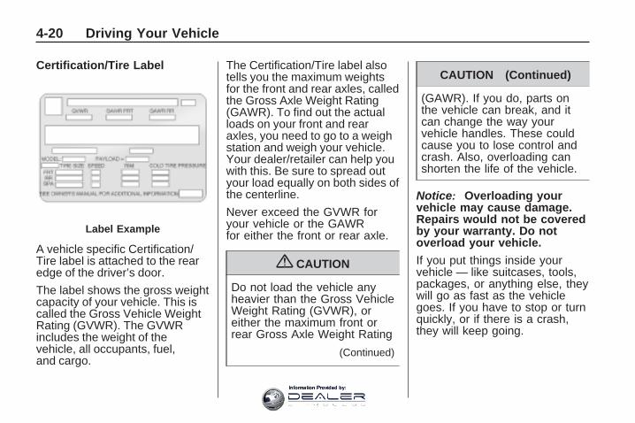
Certification/Tire Label
A vehicle specific Certification/Tire label is attached to the rearedge of the driver’s door.
The label shows the gross weightcapacity of your vehicle. This iscalled the Gross Vehicle WeightRating (GVWR). The GVWRincludes the weight of thevehicle, all occupants, fuel,and cargo.
The Certification/Tire label alsotells you the maximum weightsfor the front and rear axles, calledthe Gross Axle Weight Rating(GAWR). To find out the actualloads on your front and rearaxles, you need to go to a weighstation and weigh your vehicle.Your dealer/retailer can help youwith this. Be sure to spread outyour load equally on both sides ofthe centerline.
Never exceed the GVWR foryour vehicle or the GAWRfor either the front or rear axle.
{ CAUTION
Do not load the vehicle anyheavier than the Gross VehicleWeight Rating (GVWR), oreither the maximum front orrear Gross Axle Weight Rating
(Continued)
CAUTION (Continued)
(GAWR). If you do, parts onthe vehicle can break, and itcan change the way yourvehicle handles. These couldcause you to lose control andcrash. Also, overloading canshorten the life of the vehicle.
Notice: Overloading yourvehicle may cause damage.Repairs would not be coveredby your warranty. Do notoverload your vehicle.
If you put things inside yourvehicle — like suitcases, tools,packages, or anything else, theywill go as fast as the vehiclegoes. If you have to stop or turnquickly, or if there is a crash,they will keep going.
Label Example
4-20 Driving Your Vehicle
Information Provided by:

{ CAUTION
Things you put inside yourvehicle can strike and injurepeople in a sudden stop orturn, or in a crash.
• Put things in the cargoarea of your vehicle. Try tospread the weight evenly.
• Never stack heavier things,like suitcases, inside thevehicle so that some ofthem are above the topsof the seats.
• Do not leave an unsecuredchild restraint in yourvehicle.
• When you carry somethinginside the vehicle, secure itwhenever you can.
• Do not leave a seat foldeddown unless you need to.
Towing
Towing Your VehicleTo avoid damage, the disabledvehicle should be towed with all fourwheels off the ground. Consult yourdealer/retailer or a professionaltowing service if the disabled vehiclemust be towed. See RoadsideAssistance Program on page 7-6.
To tow the vehicle behind anothervehicle for recreational purposes,such as behind a motorhome,see “Recreational Vehicle Towing”following.
Recreational VehicleTowingRecreational vehicle towing meanstowing the vehicle behind anothervehicle – such as behind amotorhome. The two most commontypes of recreational vehicle towingare known as dinghy towing anddolly towing. Dinghy towing is towingthe vehicle with all four wheels on the
ground. Dolly towing is towing thevehicle with two wheels on theground and two wheels up on adevice known as a dolly.
Here are some important things toconsider before recreationalvehicle towing:
• What is the towing capacity of thetowing vehicle? Be sure to readthe tow vehicle manufacturer’srecommendations.
• What is the distance that will betravelled? Some vehicles haverestrictions on how far and howlong they can tow.
• Is the proper towing equipmentgoing to be used? See yourdealer/retailer or traileringprofessional for additional adviceand equipment recommendations.
• Is the vehicle ready to be towed?Just as preparing the vehicle for along trip, make sure the vehicle isprepared to be towed. See BeforeLeaving on a Long Trip onpage 4-12.
Driving Your Vehicle 4-21
Information Provided by:

Dinghy Towing
If the vehicle is front-wheel-drive, itcan be dinghy towed from the front.These vehicles may also be towedby putting the front wheels on a dolly.See “Dolly Towing” later in thissection.
If the vehicle is all-wheel-drive, it canbe dinghy towed from the front.These vehicles can also be towed byplacing them on a platform trailerwith all four wheels off of the ground.These vehicles cannot be towedusing a dolly.
For vehicles being dinghy towed,the vehicle should be run at thebeginning of each day and at eachRV fuel stop for about five minutes.This will ensure proper lubrication oftransmission components. Re-installthe fuse to start the vehicle.
To tow the vehicle from the frontwith all four wheels on the ground:
1. Position the vehicle to tow andthen secure it to the towingvehicle.
2. Shift the transmission to P (Park)and turn the ignition toLOCK/OFF.
3. Set the parking brake.
4. Turn the ignition toACC/ACCESSORY.
5. Shift the transmission toN (Neutral).
6. To prevent the battery fromdraining while the vehicle is beingtowed, remove the 50 ampBATT1 fuse from the underhoodfuse block and store in a safelocation. See Underhood FuseBlock on page 5-88.
7. Release the parking brake.
4-22 Driving Your Vehicle
Information Provided by:

Notice: If the vehicle istowed without performingeach of the steps listed under“Dinghy Towing,” the automatictransmission could be damaged.Be sure to follow all steps of thedinghy towing procedure prior toand after towing the vehicle.
Notice: If 65 mph (105 km/h) isexceeded while towing thevehicle, it could be damaged.Never exceed 65 mph (105 km/h)while towing the vehicle.
Once the destination is reached:
1. Set the parking brake.
2. Reinstall the 50 amp BATT1 fuseto the underhood fuse block.
3. Shift the transmission to P (Park),turn the ignition to LOCK/OFFand remove the key fromthe ignition.
4. Disconnect the vehicle from thetowing vehicle.
Notice: Do not tow a vehiclewith the front drive wheels on theground if one of the front tiresis a compact spare tire. Towingwith two different tire sizes on thefront of the vehicle can causesevere damage to thetransmission.
Dolly Towing (All-Wheel-DriveVehicles)
All-wheel-drive vehicles must not betowed with two wheels on theground. To properly tow thesevehicles, they should be placed ona platform trailer with all fourwheels off of the ground or dinghytowed from the front.
Driving Your Vehicle 4-23
Information Provided by:

Dolly Towing(Front-Wheel-DriveVehicles Only)
To tow a front-wheel-drive vehiclefrom the front with two wheelson the ground:
1. Put the front wheels on a dolly.
2. Move the shift lever to P (Park).
3. Set the parking brake.
4. Clamp the steering wheel in astraight-ahead position with aclamping device designedfor towing.
5. Remove the key from theignition.
6. Secure the vehicle to the dolly.
7. Release the parking brake.
Towing the Vehicle Fromthe Rear
Notice: Towing the vehicle fromthe rear could damage it. Also,repairs would not be covered bythe vehicle warranty. Never havethe vehicle towed from the rear.
Do not tow the vehicle from the rear.
4-24 Driving Your Vehicle
Information Provided by:

Towing a Trailer
{ CAUTION
The driver can lose control whenpulling a trailer if the correctequipment is not used or thevehicle is not driven properly. Forexample, if the trailer is too heavy,the brakes may not work well — oreven at all. The driver andpassengers could be seriouslyinjured. The vehicle may also bedamaged; the resulting repairswould not be covered by thevehicle warranty. Pull a trailer onlyif all the steps in this section havebeen followed. Ask your dealer/retailer for advice and informationabout towing a trailer with thevehicle.
To identify the trailering capacity ofthe vehicle, read the informationin “Weight of the Trailer” thatappears later in this section.
Trailering is different than just drivingthe vehicle by itself. Trailering meanschanges in handling, acceleration,braking, durability and fuel economy.Successful, safe trailering takescorrect equipment, and it has to beused properly.
The following information has manytime-tested, important trailering tipsand safety rules. Many of these areimportant for the safety of the driverand the passengers. So please readthis section carefully before pullinga trailer.
Load-pulling components such asthe engine, transmission, rear axle,wheel assemblies and tires areforced to work harder against thedrag of the added weight. The engineis required to operate at relativelyhigher speeds and under greaterloads, generating extra heat. What’smore, the trailer adds considerablyto wind resistance, increasing thepulling requirements.
Driving Your Vehicle 4-25
Information Provided by:

Pulling A TrailerHere are some important points:
• There are many different laws,including speed limit restrictions,having to do with trailering. Makesure the rig will be legal, not onlywhere you live but also where youwill be driving. A good source forthis information can be state orprovincial police.
• Consider using a sway control.See “Hitches” later in this section.
• Do not tow a trailer at all duringthe first 500 miles (800 km) thenew vehicle is driven. The engine,axle or other parts could bedamaged.
• Then, during the first 500 miles(800 km) that a trailer is towed, donot drive over 50 mph (80 km/h)and do not make starts at fullthrottle. This helps the engine andother parts of the vehicle wear inat the heavier loads.
• Obey speed limit restrictionswhen towing a trailer.
• The vehicles can tow in D (Drive).Shift the transmission to a lowergear if the transmission shifts toooften under heavy loads and/orhilly conditions. See “Tow/HaulMode” later in this section.
• The vehicle is designed primarilyas a passenger and load carryingvehicle. If a trailer is towed,the vehicle will require morefrequent maintenance due to theadditional load.
Three important considerations haveto do with weight:
• The weight of the trailer.
• The weight of the trailer tongue.
• And the weight on the vehicle’stires
Weight of the TrailerHow heavy can a trailer safely be?
It depends on how the rig is used.For example, speed, altitude, roadgrades, outside temperature andhow much the vehicle is used to pulla trailer are all important. It candepend on any special equipment onthe vehicle, and the amount oftongue weight the vehicle can carry.See “Weight of the Trailer Tongue”later in this section for moreinformation.
Maximum trailer weight is calculatedassuming only the driver is in the towvehicle and it has all the requiredtrailering equipment. The weight ofadditional optional equipment,passengers and cargo in the towvehicle must be subtracted from themaximum trailer weight.
Use the following chart to determinehow much the vehicle can weigh,based upon the vehicle model andoptions.
4-26 Driving Your Vehicle
Information Provided by:

Vehicle Maximum Trailer Weight *GCWRFront-Wheel Drive 2,000 lbs (907 kg) 7,500 lbs (3 402 kg)Front-Wheel Drive, V92 Trailer Towing Package 5,200 lbs (2 359 kg) 10,250 lbs (4 649 kg)All-Wheel Drive 2,000 lbs (907 kg) 7,700 lbs (3 493 kg)All-Wheel Drive, V92 Trailer Towing Package 5,200 lbs (2 359 kg) 10,450 lbs (4 740 kg)*The Gross Combination Weight Rating (GCWR) is the total allowable weight of the completely loaded vehicle andtrailer including any passengers, cargo, equipment and conversions. The GCWR for the vehicle should not beexceeded.
Ask your dealer/retailer for ourtrailering information or advice, orwrite us at our Customer AssistanceOffices. See Customer AssistanceOffices on page 7-5 for moreinformation.
Weight of the Trailer TongueThe tongue load (A) of any trailer isan important weight to measurebecause it affects the total grossweight of the vehicle. The GrossVehicle Weight (GVW) includes thecurb weight of the vehicle, any cargo
carried in it, and the people whowill be riding in the vehicle. If thereare a lot of options, equipment,passengers or cargo in the vehicle, itwill reduce the tongue weight thevehicle can carry, which will alsoreduce the trailer weight the vehiclecan tow. If towing a trailer, thetongue load must be added to theGVW because the vehicle will becarrying that weight, too. SeeLoading the Vehicle on page 4-16 formore information about the vehicle’smaximum load capacity. If a weight-carrying hitch or a
weight-distributing hitch is beingused, the trailer tongue (A) shouldweigh 10-15 percent of the totalloaded trailer weight (B).
Driving Your Vehicle 4-27
Information Provided by:

After loading the trailer, weighthe trailer and then the tongue,separately, to see if the weights areproper. If they aren’t, adjustmentsmight be made by moving someitems around in the trailer.
Trailering may also be limited bythe vehicle’s ability to carry tongueweight. Tongue weight cannot causethe vehicle to exceed the GVWR(Gross Vehicle Weight Rating) or theRGAWR (Rear Gross Axle WeightRating). The effect of additionalweight may reduce the traileringcapacity more than the total of theadditional weight.
Consider the following example:
A vehicle model base weight is5,500 lbs (2 495 kg); 2,800 lbs(1 270 kg) at the front axle and2,700 lbs (1 225 kg) at the rear axle.
It has a GVWR of 7,200 lbs(3 266 kg), a RGAWR of 4,000 lbs(1 814 kg) and a GCWR (GrossCombination Weight Rating) of14,000 lbs (6 350 kg). The trailerrating should be:
Expect tongue weight to be at least10 percent of trailer weight (850 lbs(386 kg)) and because the weightis applied well behind the rear axle,the effect on the rear axle is greaterthan just the weight itself, as muchas 1.5 times as much. The weightat the rear axle could be 850 lbs(386 kg) X 1.5 = 1,275 lbs (578 kg).Since the rear axle already weighs2,700 lbs (1 225 kg), adding1,275 lbs (578 kg) brings the total to3,975 lbs (1 803 kg). This is very
close to, but within the limit forRGAWR as well. The vehicle is set totrailer up to 8,500 lbs (3 856 kg).
If the vehicle has many options andthere is a front seat passenger andtwo rear seat passengers with someluggage and gear in the vehicle aswell. 300 lbs (136 kg) could beadded to the front axle weight and400 lbs (181 kg) to the rear axleweight. The vehicle now weighs:
Weight is still below 7,200 lbs(3 266 kg) and you might think700 additional pounds (318 kg)should be subtracted from thetrailering capacity to stay withinGCWR limits. The maximum trailerwould only be 7,800 lbs (3 538 kg).
4-28 Driving Your Vehicle
Information Provided by:

You may go further and think thetongue weight should be limitedto less than 1,000 lbs (454 kg) toavoid exceeding GVWR. But theeffect on the rear axle must still beconsidered. Because the rear axlenow weighs 3,100 lbs (1 406 kg),900 lbs (408 kg) can be put onthe rear axle without exceedingRGAWR. The effect of tongue weightis about 1.5 times the actual weight.Dividing the 900 lbs (408 kg) by 1.5leaves only 600 lbs (272 kg) oftongue weight that can be handled.Since tongue weight is usually atleast 10 percent of total loaded trailerweight, expect that the largest trailerthe vehicle can properly handle is6,000 lbs (2 721 kg).
It is important that the vehicledoes not exceed any of itsratings — GCWR, GVWR, RGAWR,Maximum Trailer Rating or TongueWeight. The only way to be sure it isnot exceeding any of these ratings isto weigh the vehicle and trailer.
Total Weight on the Vehicle’sTiresBe sure the vehicle’s tires areinflated to the upper limit for coldtires. These numbers can be foundon the Certification/Tire label. SeeLoading the Vehicle on page 4-16.Make sure not to go over the GVWlimit for the vehicle, including theweight of the trailer tongue.
HitchesIt is important to have the correcthitch equipment. Crosswinds, largetrucks going by and rough roads area few reasons why the right hitch isneeded. Here are some rules tofollow:
• The rear bumper on the vehicle isnot intended for hitches. Do notattach rental hitches or otherbumper-type hitches to it. Useonly a frame-mounted hitch thatdoes not attach to the bumper.
• Will any holes be made in thebody of the vehicle when thetrailer hitch is installed? If thereare, then be sure to seal the holeslater when the hitch is removed.If the holes are not sealed, dirt,water, and deadly carbonmonoxide (CO) from the exhaustcan get into the vehicle. SeeEngine Exhaust on page 2-30.
Driving Your Vehicle 4-29
Information Provided by:
Safety ChainsAlways attach chains between thevehicle and the trailer. Cross thesafety chains under the tongueof the trailer to help prevent thetongue from contacting the roadif it becomes separated from thehitch. Instructions about safetychains may be provided by thehitch manufacturer or by thetrailer manufacturer. Follow themanufacturer’s recommendation forattaching safety chains and do notattach them to the bumper. Alwaysleave just enough slack so the rigcan turn. Never allow safety chainsto drag on the ground.
Trailer BrakesA loaded trailer that weighs morethan 1,000 lbs (450 kg) needs tohave its own brake system thatis adequate for the weight of thetrailer. Be sure to read and follow theinstructions for the trailer brakes sothey are installed, adjusted andmaintained properly.
Because the vehicle has antilockbrakes, do not try to tap into thevehicle’s hydraulic brake system.If you do, both brake systems willnot work well, or at all.
Driving with a TrailerTowing a trailer requires a certainamount of experience. Get to knowthe rig before setting out for the openroad. Get acquainted with the feel ofhandling and braking with the addedweight of the trailer. And always keepin mind that the vehicle you aredriving is now longer and not asresponsive as the vehicle is by itself.
Before starting, check all trailerhitch parts and attachments, safetychains, electrical connectors, lamps,tires and mirror adjustments. If thetrailer has electric brakes, start thevehicle and trailer moving and thenapply the trailer brake controller byhand to be sure the brakes areworking. This checks the electricalconnection at the same time.
During the trip, check occasionally tobe sure that the load is secure, andthat the lamps and any trailer brakesare still working.
Following DistanceStay at least twice as far behind thevehicle ahead as you would whendriving the vehicle without a trailer.This can help to avoid situations thatrequire heavy braking and suddenturns.
4-30 Driving Your Vehicle
Information Provided by:

PassingMore passing distance is neededwhen towing a trailer. Because therig is longer, it is necessary to gomuch farther beyond the passedvehicle before returning to the lane.
Backing UpHold the bottom of the steering wheelwith one hand. Then, to move thetrailer to the left, move that hand tothe left. To move the trailer to theright, move your hand to the right.Always back up slowly and, ifpossible, have someone guide you.
Making Turns
Notice: Making very sharp turnswhile trailering could cause thetrailer to come in contact with thevehicle. The vehicle could bedamaged. Avoid making verysharp turns while trailering.
When turning with a trailer, makewider turns than normal. Do this sothe trailer won’t strike soft shoulders,curbs, road signs, trees or otherobjects. Avoid jerky or suddenmaneuvers. Signal well in advance.
Turn Signals When Towing aTrailerThe arrows on the instrument panelflash whenever signaling a turn orlane change. Properly hooked up,the trailer lamps also flash, tellingother drivers the vehicle is turning,changing lanes or stopping.
When towing a trailer, the arrows onthe instrument panel flash for turnseven if the bulbs on the trailer areburned out. For this reason you maythink other drivers are seeing thesignal when they are not. It isimportant to check occasionally to besure the trailer bulbs are still working.
Driving on GradesBecause of the added load of thetrailer, the vehicle’s engine mayoverheat on hot days, when going upa long or steep grade with a trailer. Ifthe engine coolant temperature gageindicates overheating, turn off the airconditioning to reduce engine load,pull off the road and stop in a safespot. Let the engine run whileparked, preferably on level ground,with the transmission in P (Park) fora few minutes before turning theengine off.
Reduce speed and shift to a lowergear before starting down a long orsteep downgrade. If the transmissionis not shifted down, the brakesmight have to be used so much thatthey would get hot and no longerwork well.
On a long uphill grade, shift downand reduce the vehicle speedto around 55 mph (88 km/h) toreduce the possibility of the engineand the transmission overheating.
Driving Your Vehicle 4-31
Information Provided by:

Tow/Haul ModeTow/Haul is a feature that assistswhen pulling a heavy trailer ora large or heavy load. The purposeof the Tow/Haul mode is to:
• Reduce the frequency andimprove the predictability oftransmission shifts when pullinga heavy trailer or a large orheavy load.
• Provide the same solid shift feelwhen pulling a heavy trailer or alarge or heavy load as whenthe vehicle is unloaded.
• Improve control of vehicle speedwhile requiring less throttle pedalactivity when pulling a heavytrailer or a large or heavy load.
• Increase the charging systemvoltage to assist in recharginga battery installed in a trailer.
Press this button located on theconsole to turn on and turn off theTow/Haul mode.
The Tow/Haul light on the instrumentpanel will come on to indicate thatTow/Haul mode has been selected.
Tow/Haul may be turned off bypressing the button again, at whichtime the indicator light on theinstrument panel will turn off. Thevehicle will automatically turn offTow/Haul every time it is started.
Tow/Haul is designed to be mosteffective when the vehicle andtrailer combined weight is at least75 percent of the vehicle’s GrossCombined Weight Rating (GCWR).
See Weight of the Trailer earlier inthis section. Tow/Haul is most usefulunder the following drivingconditions:
• When pulling a heavy trailer or alarge or heavy load through rollingterrain.
• When pulling a heavy trailer or alarge or heavy load in stop and gotraffic.
• When pulling a heavy traileror a large or heavy load in busyparking lots where improved lowspeed control of the vehicle isdesired.
Operating the vehicle in Tow/Haulwhen lightly loaded or with notrailer at all will not cause damage.However, there is no benefit to theselection of Tow/Haul when thevehicle is unloaded. Such a selectionwhen unloaded may result inunpleasant engine and transmissiondriving characteristics and reducedfuel economy. Tow/Haul isrecommended only when pulling aheavy trailer or a large or heavy load.
4-32 Driving Your Vehicle
Information Provided by:

Parking on Hills
{ CAUTION
Parking the vehicle on a hill withthe trailer attached can bedangerous. If something goeswrong, the rig could start to move.People can be injured, and boththe vehicle and the trailer can bedamaged. When possible, alwayspark the rig on a flat surface.
If parking the rig on a hill:
1. Press the brake pedal, but do notshift into P (Park) yet. Turn thewheels into the curb if facingdownhill or into traffic if facinguphill.
2. Have someone place chocksunder the trailer wheels.
3. When the wheel chocks are inplace, release the brake pedaluntil the chocks absorb the load.
4. Reapply the brake pedal. Thenapply the parking brake and shiftthe transmission into P (Park).
5. Release the brake pedal.
Leaving After Parking ona Hill1. Apply and hold the brake pedal
while you:
• start the engine,
• shift into a gear, and
• release the parking brake.
2. Let up on the brake pedal.
3. Drive slowly until the trailer isclear of the chocks.
4. Stop and have someone pick upand store the chocks.
Maintenance When TrailerTowingThe vehicle needs service moreoften when pulling a trailer. SeeScheduled Maintenance on page 6-3for more information. Things thatare especially important in traileroperation are automatic transmissionfluid, engine oil, axle lubricant, belts,cooling system and brake system.It is a good idea to inspect thesebefore and during the trip.
Check periodically to see that allhitch nuts and bolts are tight.
Trailer Wiring HarnessThe vehicle is equipped with thefollowing wiring harness for towinga trailer.
Driving Your Vehicle 4-33
Information Provided by:

Basic Trailer Wiring
The trailer wiring harness, with aseven-pin connector, is located atthe rear of the vehicle and is tied tothe vehicle’s frame. The harnessconnector can be plugged into aseven-pin universal heavy-dutytrailer connector available throughyour dealer/retailer.
The seven-wire harness containsthe following trailer circuits:
• Yellow: Left Stop/Turn Signal
• Dark Green: Right Stop/TurnSignal
• Brown: Taillamps
• Black: Ground
• Light Green: Back-up Lamps
• Red/Black: Battery Feed
• Dark Blue: Trailer Brake*
*The fuse for this circuit is installedin the underhood electrical center,but the wires are not connected.
They should be connected by yourdealer/retailer or a qualifiedservice center.
If the back-up lamp circuit is notfunctional, contact yourdealer/retailer.
If a remote (non-vehicle) battery isbeing charged, press the Tow/Haulmode switch located on the centerconsole near the climate controls.This will boost the vehicle systemvoltage and properly charge thebattery. If the trailer is too lightfor Tow/Haul mode, turn on theheadlamps (Non-HID only) as asecond way to boost the vehiclesystem and charge the battery.
Electric Trailer Brake ControlWiring Provisions
These wiring provisions for anelectric trailer brake controllerare included with the vehicle aspart of the trailer wiring package.
The instrument panel contains bluntcut wires behind the steering columnfor the electric trailer brake controller.The harness contains the followingwires:
• Red/Black: Power Supply
• White: Brake Switch Signal
• Gray: Illumination
• Dark Blue: Trailer Brake Signal
• Black: Ground
The electric trailer brake controllershould be installed by your dealer/retailer or a qualified service center.
Engine Cooling When TrailerTowingThe cooling system may temporarilyoverheat during severe operatingconditions. See Engine Overheatingon page 5-22.
4-34 Driving Your Vehicle
Information Provided by:

Service andAppearance Care
ServiceService ................................5-3Accessories andModifications .......................5-3
California Proposition 65Warning .............................5-4
California PerchlorateMaterials Requirements ........5-4
Doing Your OwnService Work ......................5-4
Adding Equipment to theOutside of the Vehicle ...........5-4
FuelFuel ....................................5-5Gasoline Octane ...................5-5Gasoline Specifications ..........5-5California Fuel ......................5-5Additives ..............................5-5Fuels in Foreign Countries ......5-6Filling the Tank .....................5-7Filling a Portable FuelContainer ...........................5-8
Checking Things Underthe HoodChecking Things Underthe Hood ............................5-9
Hood Release .......................5-9Engine CompartmentOverview ..........................5-10
Engine Oil ..........................5-11Engine Oil Life System .........5-13Engine Air Cleaner/Filter .......5-15Automatic TransmissionFluid ................................5-16
Cooling System ...................5-17Engine Coolant ...................5-17Engine Overheating .............5-22OverheatedEngine ProtectionOperating Mode .................5-23
Power Steering Fluid ............5-24Windshield Washer Fluid ......5-24Brakes ...............................5-25Battery ...............................5-28Jump Starting .....................5-29
Headlamp AimingHeadlamp Aiming ................5-33
Bulb ReplacementBulb Replacement ...............5-33Halogen Bulbs ....................5-33Taillamps, Turn Signal,Stoplamps andSidemarker Lamps .............5-33
Replacement Bulbs ..............5-34
Windshield Wiper BladeReplacementWindshield Wiper BladeReplacement .....................5-35
TiresTires ..................................5-36Tire Sidewall Labeling ..........5-37Tire Terminology andDefinitions .........................5-39
Inflation - Tire Pressure ........5-42Tire Pressure MonitorSystem .............................5-43
Tire Pressure MonitorOperation ..........................5-45
Tire Inspection andRotation ............................5-48
When It Is Time for NewTires ................................5-50
Buying New Tires ................5-50
Service and Appearance Care 5-1
Information Provided by:

Different Size Tires andWheels .............................5-52
Uniform Tire QualityGrading ............................5-52
Wheel Alignment and TireBalance ............................5-54
Wheel Replacement .............5-54Tire Chains .........................5-55If a Tire Goes Flat ...............5-56Tire Sealant andCompressor Kit ..................5-57
Tire Sealant andCompressor Kit Storage ......5-64
Changing a Flat Tire ............5-65Removing the Spare Tireand Tools .........................5-66
Removing the Flat Tireand Installing theSpare Tire ........................5-68
Secondary Latch System ......5-72Storing a Flat or SpareTire and Tools ...................5-74
Compact Spare Tire .............5-77
Appearance CareInterior Cleaning ..................5-78Fabric/Carpet ......................5-79Leather ..............................5-80
Instrument Panel, Vinyl,and Other PlasticSurfaces ...........................5-80
Care of Safety Belts ............5-80Weatherstrips ......................5-81Washing Your Vehicle ..........5-81Cleaning Exterior Lamps/Lenses .............................5-81
Finish Care .........................5-81Windshield, Backglass, andWiper Blades ....................5-82
Aluminum or Chrome-PlatedWheels and Trim ................5-83
Tires ..................................5-83Sheet Metal Damage ...........5-84Finish Damage ....................5-84Underbody Maintenance .......5-84Chemical Paint Spotting ........5-84
Vehicle IdentificationVehicle IdentificationNumber (VIN) ....................5-85
Service Parts IdentificationLabel ...............................5-85
Electrical SystemHigh Voltage Devices andWiring ..............................5-85
Add-On ElectricalEquipment ........................5-86
Windshield Wiper Fuses .......5-86Power Windows and OtherPower Options ...................5-86
Fuses and Circuit Breakers ...5-86Instrument PanelFuse Block .......................5-86
Underhood Fuse Block .........5-88
Capacities and SpecificationsCapacities andSpecifications ....................5-92
5-2 Service and Appearance Care
Information Provided by:

ServiceFor service and parts needs, visityour dealer/retailer. You will receivegenuine GM parts and GM-trainedand supported service people.
Genuine GM parts have oneof these marks:
Accessories andModificationsWhen non-dealer/non-retaileraccessories are added to the vehicle,they can affect vehicle performanceand safety, including such thingsas airbags, braking, stability, rideand handling, emissions systems,aerodynamics, durability, andelectronic systems like antilockbrakes, traction control, and stabilitycontrol. Some of these accessoriescould even cause malfunction ordamage not covered by the vehiclewarranty.
Damage to vehicle componentsresulting from the installation or useof non-GM certified parts, includingcontrol module modifications, are
not covered under the terms of thevehicle warranty and may affectremaining warranty coverage foraffected parts.
GM Accessories are designed tocomplement and function with othersystems on the vehicle. Your GMdealer/retailer can accessorizethe vehicle using genuine GMAccessories. When you go to yourGM dealer/retailer and ask forGM Accessories, you will know thatGM-trained and supported servicetechnicians will perform thework using genuine GMAccessories.
Also, see Adding Equipment to YourAirbag-Equipped Vehicle onpage 1-58.
Service and Appearance Care 5-3
Information Provided by:
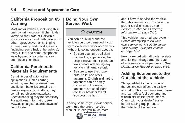
California Proposition 65WarningMost motor vehicles, including thisone, contain and/or emit chemicalsknown to the State of Californiato cause cancer and birth defects orother reproductive harm. Engineexhaust, many parts and systems(including some inside the vehicle),many fluids, and some componentwear by-products contain and/oremit these chemicals.
California PerchlorateMaterials RequirementsCertain types of automotiveapplications, such as airbaginitiators, seat belt pretensioners,and lithium batteries contained inremote keyless transmitters, maycontain perchlorate materials.Special handling may be necessary.For additional information, seewww.dtsc.ca.gov/hazardouswaste/perchlorate.
Doing Your OwnService Work
{ CAUTION
You can be injured and thevehicle could be damaged if youtry to do service work on a vehiclewithout knowing enough about it.
• Be sure you have sufficientknowledge, experience, theproper replacement parts, andtools before attempting anyvehicle maintenance task.
• Be sure to use the propernuts, bolts, and otherfasteners. English and metricfasteners can be easilyconfused. If the wrongfasteners are used, partscan later break or fall off.You could be hurt.
If doing some of your own servicework, use the proper servicemanual. It tells you much more
about how to service the vehiclethan this manual can. To order theproper service manual, seeService Publications OrderingInformation on page 7-15.
This vehicle has an airbag system.Before attempting to do yourown service work, see ServicingYour Airbag-Equipped Vehicleon page 1-57.
Keep a record with all parts receiptsand list the mileage and the dateof any service work performed. SeeMaintenance Record on page 6-16.
Adding Equipment to theOutside of the VehicleThings added to the outside ofthe vehicle can affect the airflowaround it. This can cause wind noiseand can affect fuel economy andwindshield washer performance.Check with your dealer/retailerbefore adding equipment tothe outside of the vehicle.
5-4 Service and Appearance Care
Information Provided by:
FuelUse of the recommended fuelis an important part of the propermaintenance of this vehicle. To helpkeep the engine clean and maintainoptimum vehicle performance, werecommend the use of gasolineadvertised as TOP TIER DetergentGasoline.
Gasoline OctaneUse regular unleaded gasoline with aposted octane rating of 87 or higher.If the octane rating is less than 87,you might notice an audible knockingnoise when you drive, commonlyreferred to as spark knock. If thisoccurs, use a gasoline rated at87 octane or higher as soon aspossible. If you are using gasolinerated at 87 octane or higher and youhear heavy knocking, the engineneeds service.
Gasoline SpecificationsAt a minimum, gasoline shouldmeet ASTM specification D 4814in the United States or CAN/CGSB-3.5 or 3.511 in Canada.Some gasolines contain anoctane-enhancing additive calledmethylcyclopentadienyl manganesetricarbonyl (MMT). We recommendagainst the use of gasolinescontaining MMT. See Additives onpage 5-5 for additional information.
California FuelIf the vehicle is certified to meetCalifornia Emissions Standards,it is designed to operate on fuelsthat meet California specifications.See the underhood emission controllabel. If this fuel is not available instates adopting California emissionsstandards, the vehicle will operatesatisfactorily on fuels meeting federalspecifications, but emission controlsystem performance might beaffected. The malfunction indicatorlamp could turn on and the vehicle
might fail a smog-check test. SeeMalfunction Indicator Lamp onpage 3-39. If this occurs, return toyour authorized dealer/retailer fordiagnosis. If it is determined that thecondition is caused by the type offuel used, repairs might not becovered by the vehicle warranty.
AdditivesTo provide cleaner air, all gasolinesin the United States are now requiredto contain additives that help preventengine and fuel system depositsfrom forming, allowing the emissioncontrol system to work properly.In most cases, you should not haveto add anything to the fuel. However,some gasolines contain only theminimum amount of additive requiredto meet U.S. EnvironmentalProtection Agency regulations.To help keep fuel injectors andintake valves clean, or if the vehicleexperiences problems due to dirtyinjectors or valves, look for gasolinethat is advertised as TOP TIERDetergent Gasoline.
Service and Appearance Care 5-5
Information Provided by:

For customers who do not use TOPTIER Detergent Gasoline regularly,one bottle of GM Fuel SystemTreatment PLUS, added to the fueltank at every engine oil change,can help clean deposits from fuelinjectors and intake valves. GM FuelSystem Treatment PLUS is the onlygasoline additive recommended byGeneral Motors.
Also, your dealer/retailer hasadditives that will help correct andprevent most deposit-relatedproblems.
Gasolines containing oxygenates,such as ethers and ethanol, andreformulated gasolines mightbe available in your area. Werecommend that you use thesegasolines, if they comply with thespecifications described earlier.However, E85 (85% ethanol) andother fuels containing more than10% ethanol must not be used invehicles that were not designed forthose fuels.
Notice: This vehicle was notdesigned for fuel that containsmethanol. Do not use fuelcontaining methanol. It cancorrode metal parts in the fuelsystem and also damage plasticand rubber parts. That damagewould not be covered underthe vehicle warranty.
Some gasolines that arenot reformulated for lowemissions can contain anoctane-enhancing additive calledmethylcyclopentadienyl manganesetricarbonyl (MMT); ask the attendantwhere you buy gasoline whether thefuel contains MMT. We recommendagainst the use of such gasolines.Fuels containing MMT can reducethe life of spark plugs and theperformance of the emission controlsystem could be affected. Themalfunction indicator lamp might turnon. If this occurs, return to yourdealer/retailer for service.
Fuels in ForeignCountriesIf you plan on driving in anothercountry outside the United States orCanada, the proper fuel might behard to find. Never use leadedgasoline or any other fuel notrecommended in the previous texton fuel. Costly repairs causedby use of improper fuel would notbe covered by the vehicle warranty.
To check the fuel availability, askan auto club, or contact a major oilcompany that does business inthe country where you will bedriving.
5-6 Service and Appearance Care
Information Provided by:

Filling the Tank
{ CAUTION
Fuel vapor burns violently and afuel fire can cause bad injuries.To help avoid injuries to you andothers, read and follow all theinstructions on the pump island.Turn off the engine when you arerefueling. Do not smoke if you arenear fuel or refueling the vehicle.Do not use cellular phones. Keepsparks, flames, and smokingmaterials away from fuel. Do notleave the fuel pump unattendedwhen refueling the vehicle. This isagainst the law in some places.Do not re-enter the vehicle whilepumping fuel. Keep children awayfrom the fuel pump; never letchildren pump fuel.
The tethered fuel cap is locatedbehind a hinged fuel door onthe driver side of the vehicle.
To open the fuel door, push therearward center edge in and releaseand it will open.
To remove the fuel cap, turn itslowly counterclockwise. The fuelcap has a spring in it; if the capis released too soon, it will springback to the right.
While refueling, hang the tetheredfuel cap from the hook on thefuel door.
{ CAUTION
Fuel can spray out on you ifyou open the fuel cap too quickly.If you spill fuel and then somethingignites it, you could be badlyburned. This spray can happen ifthe tank is nearly full, and is morelikely in hot weather. Open the fuelcap slowly and wait for any hissnoise to stop. Then unscrew thecap all the way.
Be careful not to spill fuel. Do nottop off or overfill the tank and wait afew seconds after you have finishedpumping before removing the nozzle.Clean fuel from painted surfaces assoon as possible. See Washing YourVehicle on page 5-81.
When replacing the fuel cap,turn it clockwise until it clicks.Make sure the cap is fully installed.
Service and Appearance Care 5-7
Information Provided by:

The diagnostic system candetermine if the fuel cap has beenleft off or improperly installed. Thiswould allow fuel to evaporate into theatmosphere. See MalfunctionIndicator Lamp on page 3-39.
If the vehicle has a Driver InformationCenter (DIC), the TIGHTEN GASCAP message displays if the fuel capis not properly installed.
{ CAUTION
If a fire starts while you arerefueling, do not remove thenozzle. Shut off the flow of fuel byshutting off the pump or bynotifying the station attendant.Leave the area immediately.
Notice: If you need a new fuelcap, be sure to get the right type.Your dealer/retailer can get one foryou. If you get the wrong type, itmight not fit properly. This cancause the malfunction indicatorlamp to light and can damage thefuel tank and emissions system.See Malfunction Indicator Lampon page 3-39.
Filling a Portable FuelContainer
{ CAUTION
Never fill a portable fuel containerwhile it is in the vehicle. Staticelectricity discharge from thecontainer can ignite the fuel vapor.
(Continued)
CAUTION (Continued)
You can be badly burned and thevehicle damaged if this occurs. Tohelp avoid injury to you and others:
• Dispense fuel only intoapproved containers.
• Do not fill a container while itis inside a vehicle, in avehicle’s trunk, pickup bed, oron any surface other than theground.
• Bring the fill nozzle in contactwith the inside of the fillopening before operating thenozzle. Contact should bemaintained until the filling iscomplete.
• Do not smoke whilepumping fuel.
• Do not use a cellular phonewhile pumping fuel.
5-8 Service and Appearance Care
Information Provided by:

Checking ThingsUnder the Hood
{ CAUTION
An electric fan under the hoodcan start up and injure you evenwhen the engine is not running.Keep hands, clothing, and toolsaway from any underhoodelectric fan.
{ CAUTION
Things that burn can get on hotengine parts and start a fire.These include liquids like fuel, oil,coolant, brake fluid, windshieldwasher and other fluids, andplastic or rubber. You or otherscould be burned. Be careful not todrop or spill things that will burnonto a hot engine.
Hood ReleaseTo open the hood, do the following:
1. Pull the hood release handle withthis symbol on it. It is locatedunder the instrument panelon the driver’s side of the vehicle.
2. At the front of the vehicle, pull upon the center of the hood, andpush the secondary hood releaseto the right.
3. After you have partially lifted thehood, gas struts will automaticallytake over to lift and hold thehood in the fully open position.
Before closing the hood, be sure allfiller caps are on properly.
Pull the hood down to close. Lowerthe hood until the lifting pressureof the strut is reduced. Then allowthe hood to fall and latch into placeunder its own weight. Check to makesure the hood is closed. If the hooddoes not fully latch, gently push thehood down at the front and center ofthe hood until it is completelylatched.
Service and Appearance Care 5-9
Information Provided by:

Engine Compartment OverviewWhen you lift the hood, here is what you will see:
5-10 Service and Appearance Care
Information Provided by:

A. Radiator Pressure Cap. SeeCooling System on page 5-17.
B. Engine Coolant Recovery Cap.See Cooling System onpage 5-17.
C. Remote Negative (−) Terminal.See Jump Starting on page 5-29.
D. Underhood Fuse Block onpage 5-88.
E. Remote Positive (+) Terminal.See Jump Starting on page 5-29.
F. Power Steering Fluid onpage 5-24.
G. Engine Oil Fill Cap. See “Whento Add Engine Oil” under EngineOil on page 5-11.
H. Engine Oil Dipstick. See“Checking Engine Oil” underEngine Oil on page 5-11.
I. Automatic TransmissionFluid Dipstick. See “Checkingthe Fluid Level” under AutomaticTransmission Fluid on page 5-16.
J. Brake Master Cylinder Reservoir.See “Brake Fluid” under Brakeson page 5-25.
K. Engine Air Cleaner/Filter onpage 5-15.
L. Windshield Washer FluidReservoir. See “Adding WasherFluid” under WindshieldWasher Fluid on page 5-24.
Engine OilChecking Engine OilIt is a good idea to check the engineoil level at each fuel fill. In order toget an accurate reading, the oil mustbe warm and the vehicle must be onlevel ground.
The engine oil dipstick handleis a yellow loop. See EngineCompartment Overview onpage 5-10 for the location of theengine oil dipstick.
1. Turn off the engine and give theoil several minutes to drain backinto the oil pan. If this is notdone, the oil dipstick might notshow the actual level.
2. Pull out the dipstick and clean itwith a paper towel or cloth, thenpush it back in all the way.Remove it again, keeping the tipdown, and check the level.
Service and Appearance Care 5-11
Information Provided by:

When to Add Engine Oil
If the oil is below the cross-hatchedarea at the tip of the dipstick,add at least one quart/liter of therecommended oil. This sectionexplains what kind of oil to use.For engine oil crankcase capacity,see Capacities and Specifications onpage 5-92.
Notice: Do not add too much oil.If the engine has so much oilthat the oil level gets above thecross-hatched area that showsthe proper operating range,the engine could be damaged.
See Engine Compartment Overviewon page 5-10 for the location ofthe engine oil fill cap.
Add enough oil to put the levelsomewhere in the proper operatingrange in the cross-hatched area.Push the dipstick all the way backin when through.
What Kind of Engine Oil to UseLook for three things:
5-12 Service and Appearance Care
Information Provided by:

• GM6094M
Use only an oil that meets GMStandard GM6094M.
• SAE 5W-30
SAE 5W-30 is best for thevehicle. These numbers on anoil container show its viscosity,or thickness. Do not use otherviscosity oils such asSAE 20W-50.
• American Petroleum Institute(API) starburst symbol
Oils meeting these requirementsshould have the starburstsymbol on the container. Thissymbol indicates that the oil hasbeen certified by the AmericanPetroleum Institute (API).
Notice: Use only engineoil identified as meeting GMStandard GM6094M and showingthe American Petroleum InstituteCertified For Gasoline Enginesstarburst symbol. Failure to usethe recommended oil can result inengine damage not covered by thevehicle warranty.
Cold Temperature OperationIf in an area of extreme cold,where the temperature fallsbelow −20°F (−29°C), use eitheran SAE 5W-30 synthetic oil or anSAE 0W-30 engine oil. Both provideeasier cold starting for the engine atextremely low temperatures. Alwaysuse an oil that meets the requiredspecification, GM6094M. See “WhatKind of Engine Oil to Use” for moreinformation.
Engine Oil Additives / EngineOil FlushesDo not add anything to the oil.The recommended oils with thestarburst symbol that meet GMStandard GM6094M are all that isneeded for good performance andengine protection.
Engine oil system flushes are notrecommended and could causeengine damage not covered by thevehicle warranty.
Engine Oil Life SystemWhen to Change Engine OilThis vehicle has a computer systemthat indicates when to change theengine oil and filter. This is basedon engine revolutions and enginetemperature, and not on mileage.Based on driving conditions, themileage at which an oil change isindicated can vary considerably. Forthe oil life system to work properly,the system must be reset every timethe oil is changed.
Service and Appearance Care 5-13
Information Provided by:

When the system has calculatedthat oil life has been diminished,it indicates that an oil change isnecessary. A CHANGE ENGINE OILSOON message comes on. Changethe oil as soon as possible withinthe next 600 miles (1 000 km). It ispossible that, if driving under the bestconditions, the oil life system mightnot indicate that an oil change isnecessary for over a year. However,the engine oil and filter must bechanged at least once a year and atthis time the system must be reset.Your dealer/retailer has trainedservice people who will perform thiswork using genuine parts and resetthe system. It is also important tocheck the oil regularly and keep it atthe proper level.
If the system is ever resetaccidentally, the oil must bechanged at 3,000 miles (5 000 km)since the last oil change. Rememberto reset the oil life system wheneverthe oil is changed.
How to Reset the Engine OilLife SystemThe Engine Oil Life Systemcalculates when to change theengine oil and filter based on vehicleuse. Whenever the oil is changed,reset the system so it can calculatewhen the next oil change is required.If a situation occurs where the oilis changed prior to a CHANGEENGINE OIL SOON message beingturned on, reset the system.
If the vehicle does not have DriverInformation Center (DIC) buttons:
1. Turn the ignition to ON/RUN, withthe engine off. The vehicle mustbe in P (Park) to access thisdisplay. Press the trip odometerreset stem until OIL LIFEREMAINING displays.
2. Press and hold the tripodometer reset stem until OILLIFE REMAINING shows 100%.Three chimes sound and theCHANGE ENGINE OIL SOONmessage goes off.
3. Turn the key to LOCK/OFF.If the CHANGE ENGINE OILSOON message comes back onwhen the vehicle is started, theengine oil life system has notreset. Repeat the procedure.
5-14 Service and Appearance Care
Information Provided by:

If the vehicle has Driver InformationCenter (DIC) buttons:
1. Turn the ignition to ON/RUN,with the engine off.
2. Press the vehicle informationbutton until OIL LIFEREMAINING displays.
3. Press and hold the set/resetbutton until 100% is displayed.Three chimes sound andthe CHANGE ENGINE OILSOON message goes off.
4. Turn the key to LOCK/OFF.
If the CHANGE ENGINE OIL SOONmessage comes back on when thevehicle is started, the engine oil lifesystem has not reset. Repeat theprocedure.
What to Do with Used OilUsed engine oil contains certainelements that can be unhealthy foryour skin and could even causecancer. Do not let used oil stay onyour skin for very long. Clean yourskin and nails with soap and water,or a good hand cleaner. Wash orproperly dispose of clothing or ragscontaining used engine oil. See themanufacturer’s warnings about theuse and disposal of oil products.
Used oil can be a threat to theenvironment. If you change your ownoil, be sure to drain all the oil from thefilter before disposal. Never disposeof oil by putting it in the trash, pouringit on the ground, into sewers, or intostreams or bodies of water. Recycleit by taking it to a place that collectsused oil.
Engine Air Cleaner/FilterWhen to Inspect the EngineAir Cleaner/FilterInspect the air cleaner/filter at theMaintenance II intervals and replaceit at the first oil change after each50,000 mile (80 000 km) interval.See Scheduled Maintenance onpage 6-3 for more information. If youare driving in dusty/dirty conditions,inspect the filter at each engine oilchange.
See Engine Compartment Overviewon page 5-10 for the location ofthe engine air cleaner/filter.
How to Inspect the Engine AirCleaner/FilterTo inspect the air cleaner/filter,remove the filter from the vehicle andlightly shake the filter (away fromvehicle) to release loose dust anddirt. If the filter remains caked withdirt, a new filter is required.
Service and Appearance Care 5-15
Information Provided by:
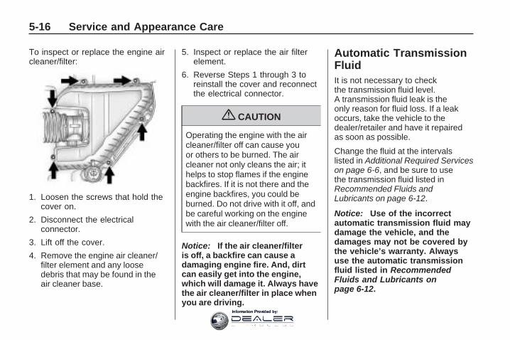
To inspect or replace the engine aircleaner/filter:
1. Loosen the screws that hold thecover on.
2. Disconnect the electricalconnector.
3. Lift off the cover.
4. Remove the engine air cleaner/filter element and any loosedebris that may be found in theair cleaner base.
5. Inspect or replace the air filterelement.
6. Reverse Steps 1 through 3 toreinstall the cover and reconnectthe electrical connector.
{ CAUTION
Operating the engine with the aircleaner/filter off can cause youor others to be burned. The aircleaner not only cleans the air; ithelps to stop flames if the enginebackfires. If it is not there and theengine backfires, you could beburned. Do not drive with it off, andbe careful working on the enginewith the air cleaner/filter off.
Notice: If the air cleaner/filteris off, a backfire can cause adamaging engine fire. And, dirtcan easily get into the engine,which will damage it. Always havethe air cleaner/filter in place whenyou are driving.
Automatic TransmissionFluidIt is not necessary to checkthe transmission fluid level.A transmission fluid leak is theonly reason for fluid loss. If a leakoccurs, take the vehicle to thedealer/retailer and have it repairedas soon as possible.
Change the fluid at the intervalslisted in Additional Required Serviceson page 6-6, and be sure to usethe transmission fluid listed inRecommended Fluids andLubricants on page 6-12.
Notice: Use of the incorrectautomatic transmission fluid maydamage the vehicle, and thedamages may not be covered bythe vehicle’s warranty. Alwaysuse the automatic transmissionfluid listed in RecommendedFluids and Lubricants onpage 6-12.
5-16 Service and Appearance Care
Information Provided by:

The transmission fluid will notreach the end of the dipstick unlessthe transmission is at operatingtemperature. If you need to check thetransmission fluid level, please takethe vehicle to your dealer/retailer.
Cooling SystemThe cooling system allows theengine to maintain the correctworking temperature.
A. Engine Coolant Recovery TankB. Radiator Pressure CapC. Engine Cooling Fans
{ CAUTION
An electric engine cooling fanunder the hood can start up evenwhen the engine is not runningand can cause injury. Keephands, clothing, and tools awayfrom any underhood electric fan.
{ CAUTION
Heater and radiator hoses, andother engine parts, can be veryhot. Do not touch them. If you do,you can be burned.
Do not run the engine if there is aleak. If you run the engine, itcould lose all coolant. That couldcause an engine fire, and youcould be burned. Get any leakfixed before you drive the vehicle.
Notice: Using coolant otherthan DEX-COOL® can causepremature engine, heater core,or radiator corrosion. In addition,the engine coolant could requirechanging sooner, at 30,000 miles(50 000 km) or 24 months,whichever occurs first. Anyrepairs would not be covered bythe vehicle warranty. Always useDEX-COOL® (silicate-free) coolantin the vehicle.
Engine CoolantThe cooling system in the vehicleis filled with DEX-COOL® enginecoolant. The coolant is designed toremain in the vehicle for five yearsor 150,000 miles (240 000 km),whichever occurs first.
The following explains the coolingsystem and how to check and addcoolant when it is low. If there is aproblem with engine overheating,see Engine Overheating onpage 5-22.
Service and Appearance Care 5-17
Information Provided by:

What to Use
{ CAUTION
Adding only plain water to thecooling system can be dangerous.Plain water, or some other liquidsuch as alcohol, can boil beforethe proper coolant mixture will.The vehicle’s coolant warningsystem is set for the propercoolant mixture. With plain wateror the wrong mixture, the enginecould get too hot but you wouldnot get the overheat warning. Theengine could catch fire and you orothers could be burned. Use a50/50 mixture of clean, drinkablewater and DEX-COOL® coolant.
Use a 50/50 mixture of clean,drinkable water and DEX-COOLcoolant. If using this mixture, nothingelse needs to be added. Thismixture:
• Gives freezing protection downto −34°F (−37°C), outsidetemperature.
• Gives boiling protection up to265°F (129°C), enginetemperature.
• Protects against rust andcorrosion.
• Will not damage aluminum parts.
• Helps keep the proper enginetemperature.
Notice: If an improper coolantmixture is used, the engine couldoverheat and be badly damaged.The repair cost would not becovered by the vehicle warranty.Too much water in the mixturecan freeze and crack the engine,radiator, heater core, and otherparts.
Notice: If extra inhibitorsand/or additives are used inthe vehicle’s cooling system,the vehicle could be damaged.Use only the proper mixture ofthe engine coolant listed inthis manual for the coolingsystem. See RecommendedFluids and Lubricants onpage 6-12 for more information.
5-18 Service and Appearance Care
Information Provided by:

Checking CoolantThe vehicle must be on a levelsurface when checking the coolantlevel.
Check to see if coolant is visible inthe coolant recovery tank. If thecoolant inside the coolant recoverytank is boiling, do not do anythingelse until it cools down. If coolant isvisible but the coolant level is not ator above the FULL COLD mark, adda 50/50 mixture of clean, drinkablewater and DEX-COOL coolant at thecoolant recovery tank, but be surethe cooling system is cool before thisis done. See Engine Coolant onpage 5-17 for more information.
The coolant recovery tank cap hasthis symbol on it.
When the engine is cold, the coolantlevel should be at or above theFULL COLD line marked on therecovery tank.
When the engine is hot, the levelcould be higher than the FULL COLDline. If the coolant is below the FULLCOLD line when the engine is hot,there could be a leak in the coolingsystem.
If the coolant is low, add the coolantor take the vehicle to a dealer/retailerfor service.
How to Add Coolant to theRecovery Tank
{ CAUTION
You can be burned if you spillcoolant on hot engine parts.Coolant contains ethylene glycoland it will burn if the engine partsare hot enough. Do not spillcoolant on a hot engine.
Notice: This vehicle has aspecific coolant fill procedure.Failure to follow this procedurecould cause the engine tooverheat and be severelydamaged.
If coolant is needed, add the properDEX-COOL® coolant mixture atthe coolant recovery tank.
Service and Appearance Care 5-19
Information Provided by:

How to Add Coolant to theRadiator
{ CAUTION
An electric engine cooling fanunder the hood can start up evenwhen the engine is not runningand can cause injury. Keephands, clothing, and tools awayfrom any underhood electric fan.
{ CAUTION
Steam and scalding liquids from ahot cooling system can blow outand burn you badly. They areunder pressure, and if you turn thesurge tank pressure cap — even alittle — they can come out at highspeed. Never turn the cap whenthe cooling system, including thesurge tank pressure cap, is hot.
(Continued)
CAUTION (Continued)
Wait for the cooling system andsurge tank pressure cap to coolif you ever have to turn thepressure cap.
If coolant is needed, add the propermixture directly to the radiator,but be sure the cooling system iscool before this is done.
1. Detach fasteners and lift offthe panel that covers theradiator cap.
2. Remove the radiator pressurecap when the cooling system,including the upper radiator hose,is no longer hot.Turn the pressure cap slowlycounterclockwise about one fullturn. If you hear a hiss, waitfor that to stop. A hiss meansthere is still some pressure leftin the system.
3. Keep turning the pressure capslowly and remove it.
4. Fill the radiator to the base ofthe filler neck with the properDEX-COOL coolant mixture.
5. When coolant begins to flow outof the filler neck, reinstall thepressure cap. Be sure to secureit tightly.
5-20 Service and Appearance Care
Information Provided by:

6. Fill the coolant recovery tank tothe FULL COLD mark.
7. Reinstall the cap on the coolantrecovery tank but leave theradiator pressure cap off.
8. Start the engine and let it rununtil the upper radiator hosefeels warm. Any time during thisprocedure, watch out for theengine cooling fan(s).
9. If the coolant level inside theradiator filler neck is low, addmore of the proper DEX-COOLcoolant mixture through thefiller neck until the level is backup to the base of the fillerneck. Replace the pressure cap.Be sure to secure it tightly.
Notice: If the pressure cap isnot tightly installed, coolant lossand possible engine damagemay occur. Be sure the cap isproperly and tightly secured.
Service and Appearance Care 5-21
Information Provided by:
Engine OverheatingThe vehicle has several indicatorsto warn of engine overheating.
There is an engine coolanttemperature gage on the instrumentpanel cluster. See Engine CoolantTemperature Gage on page 3-38.
The vehicle may also displayan ENGINE OVERHEATEDIDLE ENGINE and ENGINEOVERHEATED STOP ENGINEmessage in the Driver InformationCenter (DIC). See DIC Warnings andMessages on page 3-56.
You may decide not to lift the hoodwhen this warning appears, butinstead get service help right away.See Roadside Assistance Programon page 7-6.
If you do decide to lift the hood,make sure the vehicle is parkedon a level surface.
Then check to see if the enginecooling fans are running. If theengine is overheating, both fansshould be running. If they arenot, do not continue to run theengine and have the vehicleserviced.
Notice: Engine damage fromrunning the engine withoutcoolant is not covered by thewarranty.
Notice: If the engine catches firewhile driving with no coolant,the vehicle can be badlydamaged. The costly repairswould not be covered bythe vehicle warranty. SeeOverheated Engine ProtectionOperating Mode on page 5-23 forinformation on driving to asafe place in an emergency.
If Steam Is Coming From TheEngine Compartment
{ CAUTION
Steam from an overheated enginecan burn you badly, even if youjust open the hood. Stay awayfrom the engine if you see or hearsteam coming from it. Turn it offand get everyone away from thevehicle until it cools down. Waituntil there is no sign of steam orcoolant before you open the hood.
If you keep driving when thevehicles engine is overheated, theliquids in it can catch fire. You orothers could be badly burned.Stop the engine if it overheats,and get out of the vehicle until theengine is cool.
See Overheated Engine ProtectionOperating Mode on page 5-23 forinformation on driving to a safeplace in an emergency.
5-22 Service and Appearance Care
Information Provided by:

If No Steam Is Coming FromThe Engine CompartmentIf an engine overheat warning isdisplayed but no steam can be seenor heard, the problem may not betoo serious. Sometimes theengine can get a little too hot whenthe vehicle:
• Climbs a long hill on a hot day.
• Stops after high-speed driving.
• Idles for long periods in traffic.
• Tows a trailer.
If the overheat warning is displayedwith no sign of steam:
1. Turn the air conditioning off.
2. Turn the heater on to the highesttemperature and to the highestfan speed. Open the windows asnecessary.
3. If in a traffic jam, shift toN (Neutral), otherwise, shiftto the highest gear whiledriving —D (Drive) or L (Low).
If the temperature overheat gage isno longer in the overheat zone or anoverheat warning no longer displays,the vehicle can be driven. Continueto drive the vehicle slow for about10 minutes. Keep a safe vehicledistance from the car in front of you.If the warning does not come backon, continue to drive normally.
If the warning continues, pull over,stop, and park the vehicle right away.
If there is no sign of steam, idlethe engine for three minutes whileparked. If the warning is stilldisplayed, turn off the engine until itcools down. Also, see “OverheatedEngine Protection Operating Mode”next in this section.
OverheatedEngine ProtectionOperating ModeThis emergency operating mode letsthe vehicle be driven to a safe placein an emergency situation. If anoverheated engine condition exists,an overheat protection mode whichalternates firing groups of cylindershelps prevent engine damage. In thismode, there is a significant loss inpower and engine performance.The temperature gage indicates anoverheat condition exists. Drivingextended distances and/or towing atrailer in the overheat protectionmode should be avoided.
Notice: After driving in theoverheated engine protectionoperating mode, to avoid enginedamage, allow the engine to coolbefore attempting any repair.The engine oil will be severelydegraded. Repair the cause ofcoolant loss, change the oil andreset the oil life system. SeeEngine Oil on page 5-11.
Service and Appearance Care 5-23
Information Provided by:

Power Steering Fluid
The power steering fluid reservoiris located toward the front of theengine compartment on thepassenger side of the vehicle. SeeEngine Compartment Overview onpage 5-10 for reservoir location.
When to Check PowerSteering FluidIt is not necessary to regularlycheck power steering fluid unlessyou suspect there is a leak inthe system or you hear an unusualnoise. A fluid loss in this systemcould indicate a problem. Have thesystem inspected and repaired.
How to Check Power Steering Fluid
To check the power steeringfluid:
1. Turn the key off and let theengine compartment cool down.
2. Remove engine oil fill cap.
3. Slide engine cover rearward andlift to remove.
4. Wipe the cap and the top of thereservoir clean.
5. Unscrew the cap and wipe thedipstick with a clean rag.
6. Replace the cap and completelytighten it.
7. Remove the cap again and lookat the fluid level on the dipstick.
The fluid level should be somewherebetween MAX and MIN line on thedipstick in room temperature. If thefluid is on or below MIN line, youshould add fluid close to MAX Line.
What to UseTo determine what kind of fluid touse, see Recommended Fluids andLubricants on page 6-12. Alwaysuse the proper fluid.
Notice: Use of the incorrect fluidmay damage the vehicle and thedamages may not be covered bythe vehicle’s warranty. Alwaysuse the correct fluid listed inRecommended Fluids andLubricants on page 6-12.
Windshield Washer FluidWhat to UseWhen adding windshieldwasher fluid, be sure to read themanufacturer’s instructions beforeuse. If the vehicle will be operating inan area where the temperature mayfall below freezing, use a fluid thathas sufficient protection againstfreezing.
5-24 Service and Appearance Care
Information Provided by:

Adding Washer FluidWhen the windshield washer fluidreservoir is low, a WASHER FLUIDLOW ADD FLUID message will bedisplayed on the Driver InformationCenter (DIC). See DIC Warnings andMessages on page 3-56 for moreinformation.
Open the cap with the washersymbol on it. Add washer fluiduntil the tank is full. See EngineCompartment Overview onpage 5-10 for reservoir location.
Notice:
• When using concentratedwasher fluid, follow themanufacturer’s instructionsfor adding water.
• Do not mix water withready-to-use washer fluid.Water can cause the solution tofreeze and damage your washerfluid tank and other parts of thewasher system. Also, waterdoes not clean as well aswasher fluid.
• Fill the washer fluid tank onlythree-quarters full when it isvery cold. This allows for fluidexpansion if freezing occurs,which could damage the tank ifit is completely full.
• Do not use engine coolant(antifreeze) in your windshieldwasher. It can damage thevehicle’s windshield washersystem and paint.
BrakesBrake Fluid
The brake master cylinder reservoiris filled with DOT 3 brake fluid. SeeEngine Compartment Overview onpage 5-10 for the location of thereservoir.
Service and Appearance Care 5-25
Information Provided by:

There are only two reasons why thebrake fluid level in the reservoirmight go down:
• The brake fluid level goes downbecause of normal brake liningwear. When new linings areinstalled, the fluid level goesback up.
• A fluid leak in the brake hydraulicsystem can also cause a low fluidlevel. Have the brake hydraulicsystem fixed, since a leak meansthat sooner or later the brakes willnot work well.
Do not top off the brake fluid. Addingfluid does not correct a leak. If fluidis added when the linings are worn,there will be too much fluid when newbrake linings are installed. Add orremove brake fluid, as necessary,only when work is done on the brakehydraulic system.
{ CAUTION
If too much brake fluid is added, itcan spill on the engine and burn, ifthe engine is hot enough. You orothers could be burned, and thevehicle could be damaged. Addbrake fluid only when work is doneon the brake hydraulic system.
When the brake fluid falls to a lowlevel, the brake warning light comeson. See Brake System WarningLight on page 3-36.
What to Add
Use only new DOT 3 brake fluidfrom a sealed container. SeeRecommended Fluids andLubricants on page 6-12.
Always clean the brake fluidreservoir cap and the area aroundthe cap before removing it. Thishelps keep dirt from enteringthe reservoir.
{ CAUTION
With the wrong kind of fluid in thebrake hydraulic system, thebrakes might not work well. Thiscould cause a crash. Always usethe proper brake fluid.
5-26 Service and Appearance Care
Information Provided by:

Notice:
• Using the wrong fluid can badlydamage brake hydraulic systemparts. For example, just a fewdrops of mineral-based oil,such as engine oil, in the brakehydraulic system can damagebrake hydraulic system parts sobadly that they will have to bereplaced. Do not let someoneput in the wrong kind of fluid.
• If brake fluid is spilled on thevehicle’s painted surfaces, thepaint finish can be damaged. Becareful not to spill brake fluidon the vehicle. If you do, wash itoff immediately. See WashingYour Vehicle on page 5-81.
Brake WearThis vehicle has disc brakes. Discbrake pads have built-in wearindicators that make a high-pitchedwarning sound when the brakepads are worn and new pads areneeded. The sound can comeand go or be heard all the time thevehicle is moving, except whenapplying the brake pedal firmly.
{ CAUTION
The brake wear warning soundmeans that soon the brakes willnot work well. That could lead toan accident. When the brake wearwarning sound is heard, have thevehicle serviced.
Notice: Continuing to drive withworn-out brake pads couldresult in costly brake repair.
Some driving conditions or climatescan cause a brake squeal when thebrakes are first applied or lightlyapplied. This does not meansomething is wrong with the brakes.
Properly torqued wheel nuts arenecessary to help prevent brakepulsation. When tires are rotated,inspect brake pads for wear andevenly tighten wheel nuts inthe proper sequence to torquespecifications in Capacities andSpecifications on page 5-92.
Brake linings should always bereplaced as complete axle sets.
Brake Pedal TravelSee your dealer/retailer if the brakepedal does not return to normalheight, or if there is a rapid increasein pedal travel. This could be a signthat brake service might be required.
Service and Appearance Care 5-27
Information Provided by:

Brake AdjustmentEvery time the brakes are applied,with or without the vehicle moving,the brakes adjust for wear.
Replacing Brake System PartsThe braking system on a vehicle iscomplex. Its many parts have to beof top quality and work well togetherif the vehicle is to have really goodbraking. The vehicle was designedand tested with top-quality brakeparts. When parts of the brakingsystem are replaced — for example,when the brake linings wear downand new ones are installed — besure to get new approvedreplacement parts. If this is notdone, the brakes might not workproperly. For example, if someoneputs in brake linings that arewrong for the vehicle, the balancebetween the front and rear brakescan change — for the worse. Thebraking performance expected canchange in many other ways if thewrong replacement brake parts areinstalled.
BatteryThis vehicle has a maintenance freebattery. When it is time for a newbattery, see your dealer/retailer forone that has the replacementnumber shown on the originalbattery’s label.
For battery replacement, see yourdealer/retailer or the service manual.To purchase a service manual,see Service Publications OrderingInformation on page 7-15.Warning: Battery posts, terminals,and related accessories containlead and lead compounds,chemicals known to the State ofCalifornia to cause cancer andreproductive harm. Wash handsafter handling.
Vehicle Storage
{ CAUTION
Batteries have acid that can burnyou and gas that can explode.You can be badly hurt if you arenot careful. See Jump Startingon page 5-29 for tips on workingaround a battery withoutgetting hurt.
Infrequent Usage: If the vehicle isdriven infrequently, remove theblack, negative (−) cable from thebattery. This helps keep the batteryfrom running down.
Extended Storage: For extendedstorage of the vehicle, remove theblack, negative (−) cable from thebattery or use a battery tricklecharger. This helps maintain thecharge of the battery over anextended period of time.
5-28 Service and Appearance Care
Information Provided by:

Jump StartingIf the vehicle’s battery has rundown, you may want to use anothervehicle and some jumper cablesto start your vehicle. Be sure to usethe following steps to do it safely.
{ CAUTION
Batteries can hurt you. They canbe dangerous because:
• They contain acid that canburn you.
• They contain gas that canexplode or ignite.
• They contain enoughelectricity to burn you.
If you do not follow these stepsexactly, some or all of thesethings can hurt you.
Notice: Ignoring these stepscould result in costly damage tothe vehicle that would not becovered by the warranty.
Trying to start the vehicle bypushing or pulling it will not work,and it could damage the vehicle.
1. Check the other vehicle. Itmust have a 12-volt battery witha negative ground system.
Notice: If the other vehicle’ssystem is not a 12-volt systemwith a negative ground, bothvehicles can be damaged. Onlyuse vehicles with 12-volt systemswith negative grounds to jumpstart your vehicle.
2. Get the vehicles close enough sothe jumper cables can reach, butbe sure the vehicles are nottouching each other. If they are, itcould cause a ground connectionyou do not want. You would notbe able to start your vehicle, andthe bad grounding could damagethe electrical systems.To avoid the possibility of thevehicles rolling, set the parkingbrake firmly on both vehiclesinvolved in the jump startprocedure. Put an automatictransmission in P (Park) or amanual transmission in Neutralbefore setting the parking brake.If one of the vehicles is afour-wheel-drive vehicle, be surethe transfer case is not in Neutral.
Service and Appearance Care 5-29
Information Provided by:

Notice: If you leave the radio orother accessories on during thejump starting procedure, theycould be damaged. The repairswould not be covered by thewarranty. Always turn off theradio and other accessorieswhen jump starting the vehicle.
3. Turn off the ignition on bothvehicles. Unplug unnecessaryaccessories plugged into thecigarette lighter or the accessorypower outlets. Turn off the radioand all lamps that are not needed.This will avoid sparks and helpsave both batteries. And it couldsave the radio!
4. Open the hoods and locate thepositive (+) and negative (−)terminal locations on the othervehicle. Your vehicle has aremote positive (+) and a remotenegative (−) jump startingterminal. See EngineCompartment Overview onpage 5-10 for more informationon the terminal locations.
{ CAUTION
Using a match near a battery cancause battery gas to explode.People have been hurt doing this,and some have been blinded. Usea flashlight if you need more light.
Be sure the batteries haveenough water. You do not need toadd water to the ACDelco®
battery (or batteries) installed inyour new vehicle. But if a batteryhas filler caps, be sure the rightamount of fluid is there. If it islow, add water to take care of thatfirst. If you do not, explosive gascould be present.
Battery fluid contains acid thatcan burn you. Do not get it onyou. If you accidentally get it inyour eyes or on your skin, flushthe place with water and getmedical help immediately.
{ CAUTION
Fans or other moving engineparts can injure you badly. Keepyour hands away from movingparts once the engine is running.
5. Check that the jumper cables donot have loose or missinginsulation. If they do, you couldget a shock. The vehiclescould be damaged too.Before you connect the cables,here are some basic things youshould know. Positive (+) will goto positive (+) or to a remotepositive (+) terminal if the vehiclehas one. Negative (−) will go to aheavy, unpainted metal enginepart or to a remote negative (−)terminal if the vehicle has one.
5-30 Service and Appearance Care
Information Provided by:

Do not connect positive (+) tonegative (−) or you will get a shortthat would damage the batteryand maybe other parts too. Anddo not connect the negative (−)cable to the negative (−) terminalon the dead battery because thiscan cause sparks.
6. Connect the red positive (+)cable to the positive (+) terminalof the dead battery.Use a remote positive (+)terminal if the vehicle has one.
7. Do not let the other endtouch metal. Connect it to thepositive (+) terminal of the goodbattery. Use a remote positive (+)terminal if the vehicle has one.
8. Now connect the blacknegative (−) cable to thenegative (−) terminal of thegood battery. Use a remotenegative (−) terminal if thevehicle has one.Do not let the other end touchanything until the next step. Theother end of the negative (−)cable does not go to the deadbattery. It goes to a heavy,unpainted metal engine part, or toa remote negative (−) terminal onthe vehicle with the dead battery.
9. Connect the other end of thenegative (−) cable at least18 inches (45 cm) away from thedead battery, but not near engineparts that move.The electrical connection is justas good there, and the chanceof sparks getting back to thebattery is much less.Your vehicle has a remotenegative (−) terminal for thispurpose.
Service and Appearance Care 5-31
Information Provided by:

10. Now start the vehicle with thegood battery and run theengine for a while.
11. Try to start the vehicle that hadthe dead battery. If it will notstart after a few tries, it probablyneeds service.
Notice: If the jumper cables areconnected or removed in thewrong order, electrical shortingmay occur and damage thevehicle. The repairs would not becovered by the vehicle warranty.Always connect and remove thejumper cables in the correct order,making sure that the cables do nottouch each other or other metal.
A. Heavy, Unpainted Metal EnginePart or Remote Negative (−)Terminal
B. Good Battery or RemotePositive (+) and RemoteNegative (−) Terminals
C. Dead Battery or RemotePositive (+) Terminal
To disconnect the jumper cablesfrom both vehicles, do the following:
1. Disconnect the black negative (−)cable from the vehicle that hadthe dead battery.
2. Disconnect the black negative (−)cable from the vehicle with thegood battery.
3. Disconnect the red positive (+)cable from the vehicle with thegood battery.
4. Disconnect the red positive (+)cable from the other vehicle.
Jumper Cable Removal
5-32 Service and Appearance Care
Information Provided by:

Headlamp AimingHeadlamp aim has been preset atthe factory and should need nofurther adjustment.
However, if your vehicle is damagedin a crash, the headlamp aim maybe affected. Aim adjustment tothe low-beam headlamps may benecessary if oncoming drivers flashtheir high-beam headlamps atyou (for vertical aim).
If the headlamps need to bere-aimed, it is recommended thatyou take the vehicle to yourdealer/retailer for service.
Bulb ReplacementFor the proper type of replacementbulbs, see Replacement Bulbson page 5-34.
For any bulb changing procedurenot listed in this section, contactyour dealer/retailer.
Halogen Bulbs
{ CAUTION
Halogen bulbs have pressurizedgas inside and can burst if youdrop or scratch the bulb. You orothers could be injured. Be sureto read and follow the instructionson the bulb package.
Taillamps, Turn Signal,Stoplamps andSidemarker Lamps
A. Sidemarker LampB. Taillamp
To replace one of these bulbs:
1. Open the liftgate. See Liftgate onpage 2-10 or Power Liftgate onpage 2-11.
2. Remove the convenience net, ifthe vehicle has one.
Service and Appearance Care 5-33
Information Provided by:

3. Remove the two taillamp nutcovers.
4. Remove the two nuts holding thetaillamp assembly in place.
5. Pull out the taillamp assembly.
6. Turn the bulb socketcounterclockwise and pull itstraight out to remove it from thetaillamp assembly.
7. Pull the old bulb straight out ofthe bulb socket.
8. Push the new bulb straight intothe bulb socket until it connects.
9. Push the taillamp assembly backinto its original location.When reinstalling the taillampassembly, make sure the pin onthe taillamp assembly linesup and is inserted correctly intothe opening of the vehicle.
10. Reinstall the two nuts that holdthe taillamp assembly in place.
11. Reinstall the two taillamp nutcovers.
Replacement Bulbs
Exterior Lamp BulbNumber
License Plate Lamp 194Rear SidemarkerLamp 194
Rear Turn Signaland Taillamps
7443(W21/5W)
For replacement bulbs not listedhere, contact your dealer/retailer.
5-34 Service and Appearance Care
Information Provided by:

Windshield WiperBlade ReplacementWindshield wiper blades should beinspected for wear or cracking.See Scheduled Maintenanceon page 6-3 for more information.
Replacement blades come indifferent types and are removed indifferent ways. To replace thewiper blade assembly:
1. Pull the windshield wiperarm away from thewindshield.
2. Press the button in the middle ofthe wiper arm connector and pullthe wiper blade away from thearm connector.
3. Install the new wiper blade andmake sure the wiper bladelocks into place.
For the proper size and type seeMaintenance Replacement Parts onpage 6-14.
Backglass Wiper BladeTo replace the backglass wiperblade:
1. Pull the wiper blade assemblyaway from the backglass.The backglass wiper blade willnot lock in a vertical positionso care should be used whenpulling it away from the vehicle.
2. Rotate the wiper blade assembly,hold the wiper arm in position,and push the blade awayfrom the wiper arm.
3. Replace the wiper blade.
4. Return the wiper arm and bladeassembly to the rest position onthe glass.
Service and Appearance Care 5-35
Information Provided by:

TiresYour new vehicle comeswith high-quality tires madeby a leading tire manufacturer.If you ever have questions aboutyour tire warranty and where toobtain service, see your vehicleWarranty booklet for details. Foradditional information refer to thetire manufacturer.
{ CAUTION
Poorly maintained andimproperly used tires aredangerous.
• Overloading yourvehicle’s tires can causeoverheating as a resultof too much flexing. Youcould have an air-out anda serious accident. SeeLoading the Vehicle onpage 4-16.
• Underinflated tires posethe same danger asoverloaded tires. Theresulting accident couldcause serious injury.
(Continued)
CAUTION (Continued)
Check all tires frequentlyto maintain therecommended pressure.Tire pressure should bechecked when yourvehicle’s tires are cold.See Inflation - TirePressure on page 5-42.
• Overinflated tires are morelikely to be cut, punctured,or broken by a suddenimpact — such as whenyou hit a pothole. Keeptires at the recommendedpressure.
• Worn, old tires can causeaccidents. If the tire’stread is badly worn, orif your vehicle’s tireshave been damaged,replace them.
5-36 Service and Appearance Care
Information Provided by:

Tire Sidewall LabelingUseful information about a tire ismolded into its sidewall. Theexamples below show a typicalpassenger vehicle tire and acompact spare tire sidewall.
(A) Tire Size: The tire sizeis a combination of lettersand numbers used to definea particular tire’s width, height,aspect ratio, constructiontype, and service description.
See the “Tire Size” illustrationlater in this section for moredetail.
(B) TPC Spec (TirePerformance CriteriaSpecification): Originalequipment tires designed toGM’s specific tire performancecriteria have a TPC specificationcode molded onto the sidewall.GM’s TPC specifications meetor exceed all federal safetyguidelines.
(C) DOT (Department ofTransportation): TheDepartment of Transportation(DOT) code indicates that the tireis in compliance with the U.S.Department of TransportationMotor Vehicle Safety Standards.
(D) Tire Identification Number(TIN): The letters and numbersfollowing DOT (Departmentof Transportation) code is theTire Identification Number (TIN).
The TIN shows the manufacturerand plant code, tire size, anddate the tire was manufactured.The TIN is molded onto bothsides of the tire, although onlyone side may have the date ofmanufacture.
(E) Tire Ply Material: The typeof cord and number of plies in thesidewall and under the tread.
(F) Uniform Tire QualityGrading (UTQG): Tiremanufacturers are required tograde tires based on threeperformance factors: treadwear,traction, and temperatureresistance. For more informationsee Uniform Tire QualityGrading on page 5-52.
(G) Maximum Cold InflationLoad Limit: Maximum load thatcan be carried and the maximumpressure needed to supportthat load.
Passenger (P-Metric) TireExample
Service and Appearance Care 5-37
Information Provided by:

(A) Temporary Use Only:The compact spare tire ortemporary use tire has a tread lifeof approximately 3,000 miles(5 000 km) and should not bedriven at speeds over 65 mph(105 km/h). The compact sparetire is for emergency use when aregular road tire has lost air andgone flat. If your vehicle has acompact spare tire, see CompactSpare Tire on page 5-77 and If aTire Goes Flat on page 5-56.
(B) Tire Ply Material: The typeof cord and number of plies in thesidewall and under the tread.
(C) Tire Identification Number(TIN): The letters and numbersfollowing the DOT (Departmentof Transportation) code is theTire Identification Number (TIN).The TIN shows the manufacturerand plant code, tire size, anddate the tire was manufactured.The TIN is molded onto bothsides of the tire, although onlyone side may have the date ofmanufacture.
(D) Maximum Cold InflationLoad Limit: Maximum load thatcan be carried and the maximumpressure needed to supportthat load.
(E) Tire Inflation: Thetemporary use tire or compactspare tire should be inflated to60 psi (420 kPa). For moreinformation on tire pressure andinflation see Inflation - TirePressure on page 5-42.
(F) Tire Size: A combination ofletters and numbers define atire’s width, height, aspect ratio,construction type, and servicedescription. The letter T asthe first character in the tire sizemeans the tire is for temporaryuse only.
(G) TPC Spec (TirePerformance CriteriaSpecification): Originalequipment tires designed toGM’s specific tire performancecriteria have a TPC specificationcode molded onto the sidewall.GM’s TPC specifications meetor exceed all federal safetyguidelines.
Compact Spare Tire Example
5-38 Service and Appearance Care
Information Provided by:

Tire Size
The following illustration showsan example of a typicalpassenger vehicle tire size.
(A) Passenger (P-Metric) Tire:The United States version of ametric tire sizing system. Theletter P as the first character inthe tire size means a passengervehicle tire engineered tostandards set by the U.S. Tireand Rim Association.
(B) Tire Width: The three-digitnumber indicates the tire sectionwidth in millimeters from sidewallto sidewall.
(C) Aspect Ratio: A two-digitnumber that indicates the tireheight-to-width measurements.For example, if the tire sizeaspect ratio is 60, as shown initem C of the illustration, it wouldmean that the tire’s sidewall is60 percent as high as it is wide.
(D) Construction Code: A lettercode is used to indicate the typeof ply construction in the tire.The letter R means radial plyconstruction; the letter D meansdiagonal or bias ply construction;and the letter B meansbelted-bias ply construction.
(E) Rim Diameter: Diameter ofthe wheel in inches.
(F) Service Description: Thesecharacters represent the loadindex and speed rating of the tire.The load index represents theload carry capacity a tire iscertified to carry. The speedrating is the maximum speed atire is certified to carry a load.
Tire Terminology andDefinitionsAir Pressure: The amount of airinside the tire pressing outwardon each square inch of the tire.Air pressure is expressed inpounds per square inch (psi)or kilopascal (kPa).
Accessory Weight: This meansthe combined weight of optionalaccessories. Some examplesof optional accessories are,automatic transmission, powersteering, power brakes, powerwindows, power seats, and airconditioning.
Aspect Ratio: The relationshipof a tire’s height to its width.
Belt: A rubber coated layer ofcords that is located between theplies and the tread. Cords maybe made from steel or otherreinforcing materials.
Service and Appearance Care 5-39
Information Provided by:

Bead: The tire bead containssteel wires wrapped by steelcords that hold the tire ontothe rim.
Bias Ply Tire: A pneumatictire in which the plies are laidat alternate angles less than90 degrees to the centerline ofthe tread.
Cold Tire Pressure: Theamount of air pressure in a tire,measured in pounds per squareinch (psi) or kilopascals (kPa)before a tire has built up heatfrom driving. See Inflation - TirePressure on page 5-42.
Curb Weight: The weight of amotor vehicle with standardand optional equipment includingthe maximum capacity of fuel,oil, and coolant, but withoutpassengers and cargo.
DOT Markings: A codemolded into the sidewall of atire signifying that the tire is incompliance with the U.S.Department of Transportation(DOT) motor vehicle safetystandards. The DOT codeincludes the Tire IdentificationNumber (TIN), an alphanumericdesignator which can alsoidentify the tire manufacturer,production plant, brand, and dateof production.
GVWR: Gross Vehicle WeightRating. See Loading the Vehicleon page 4-16.
GAWR FRT: Gross Axle WeightRating for the front axle. SeeLoading the Vehicle onpage 4-16.
GAWR RR: Gross Axle WeightRating for the rear axle. SeeLoading the Vehicle onpage 4-16.
Intended Outboard Sidewall:The side of an asymmetrical tire,that must always face outwardwhen mounted on a vehicle.
Kilopascal (kPa): The metricunit for air pressure.
Light Truck (LT-Metric) Tire:A tire used on light duty trucksand some multipurposepassenger vehicles.
Load Index: An assignednumber ranging from 1 to 279that corresponds to the loadcarrying capacity of a tire.
Maximum Inflation Pressure:The maximum air pressure towhich a cold tire can be inflated.The maximum air pressure ismolded onto the sidewall.
Maximum Load Rating:The load rating for a tire at themaximum permissible inflationpressure for that tire.
5-40 Service and Appearance Care
Information Provided by:

Maximum Loaded VehicleWeight: The sum of curbweight, accessory weight,vehicle capacity weight, andproduction options weight.
Normal Occupant Weight: Thenumber of occupants a vehicleis designed to seat multiplied by150 lbs (68 kg). See Loadingthe Vehicle on page 4-16.
Occupant Distribution:Designated seating positions.
Outward Facing Sidewall: Theside of an asymmetrical tire thathas a particular side that facesoutward when mounted on avehicle. The side of the tire thatcontains a whitewall, bears whitelettering, or bears manufacturer,brand, and/or model namemolding that is higher or deeperthan the same moldings on theother sidewall of the tire.
Passenger (P-Metric) Tire:A tire used on passenger carsand some light duty trucks andmultipurpose vehicles.
Recommended InflationPressure: Vehiclemanufacturer’s recommendedtire inflation pressure asshown on the tire placard. SeeInflation - Tire Pressure onpage 5-42 and Loading theVehicle on page 4-16.
Radial Ply Tire: A pneumatictire in which the ply cords thatextend to the beads are laid at90 degrees to the centerline ofthe tread.
Rim: A metal support for a tireand upon which the tire beadsare seated.
Sidewall: The portion of a tirebetween the tread and the bead.
Speed Rating: An alphanumericcode assigned to a tire indicatingthe maximum speed at which atire can operate.
Traction: The friction betweenthe tire and the road surface.The amount of grip provided.
Tread: The portion of a tire thatcomes into contact with the road.
Treadwear Indicators: Narrowbands, sometimes called wearbars, that show across the treadof a tire when only 1/16 inch(1.6 mm) of tread remains. SeeWhen It Is Time for New Tires onpage 5-50.
UTQGS (Uniform Tire QualityGrading Standards): A tireinformation system that providesconsumers with ratings for a tire’straction, temperature, andtreadwear. Ratings aredetermined by tire manufacturersusing government testingprocedures. The ratings aremolded into the sidewall of thetire. See Uniform Tire QualityGrading on page 5-52.
Service and Appearance Care 5-41
Information Provided by:

Vehicle Capacity Weight: Thenumber of designated seatingpositions multiplied by 150 lbs(68 kg) plus the rated cargo load.See Loading the Vehicle onpage 4-16.
Vehicle Maximum Load on theTire: Load on an individual tiredue to curb weight, accessoryweight, occupant weight, andcargo weight.
Vehicle Placard: A labelpermanently attached to avehicle showing the vehicle’scapacity weight and theoriginal equipment tire sizeand recommended inflationpressure. See “Tire and LoadingInformation Label” under Loadingthe Vehicle on page 4-16.
Inflation - Tire PressureTires need the correct amount ofair pressure to operateeffectively.
Notice: Do not let anyone tellyou that under-inflation orover-inflation is all right. It isnot. If your tires do not haveenough air (under-inflation),you can get the following:• Too much flexing• Too much heat• Tire overloading• Premature or irregular wear• Poor handling• Reduced fuel economyIf your tires have too much air(over-inflation), you can getthe following:• Unusual wear• Poor handling• Rough ride• Needless damage from road
hazards
A vehicle specific Tire andLoading Information label isattached to your vehicle. Thislabel shows your vehicle’soriginal equipment tires and thecorrect inflation pressures foryour tires when they are cold.The recommended cold tireinflation pressure, shown on thelabel, is the minimum amount ofair pressure needed to supportyour vehicle’s maximum loadcarrying capacity.
For additional informationregarding how much weightyour vehicle can carry, and anexample of the Tire and LoadingInformation label, see Loadingthe Vehicle on page 4-16. Howyou load your vehicle affectsvehicle handling and ridecomfort. Never load your vehiclewith more weight than it wasdesigned to carry.
5-42 Service and Appearance Care
Information Provided by:

When to Check
Check your tires once a monthor more. Do not forget to checkthe compact spare tire, if thevehicle has one. It should be at60 psi (420 kPa). For additionalinformation regarding thecompact spare tire, see CompactSpare Tire on page 5-77.
How to Check
Use a good quality pocket-typegage to check tire pressure.You cannot tell if your tires areproperly inflated simply bylooking at them. Radial tires maylook properly inflated even whenthey are under-inflated. Checkthe tire’s inflation pressure whenthe tires are cold. Cold meansyour vehicle has been sitting forat least three hours or driven nomore than 1 mile (1.6 km).
Remove the valve cap fromthe tire valve stem. Press thetire gage firmly onto the valve toget a pressure measurement.If the cold tire inflation pressurematches the recommendedpressure on the Tire and LoadingInformation label, no furtheradjustment is necessary. If theinflation pressure is low, add airuntil you reach the recommendedamount.
If you overfill the tire, releaseair by pushing on the metal stemin the center of the tire valve.Re-check the tire pressure withthe tire gage.
Be sure to put the valve capsback on the valve stems.They help prevent leaks bykeeping out dirt and moisture.
Tire Pressure MonitorSystemThe Tire Pressure Monitor System(TPMS) uses radio and sensortechnology to check tire pressurelevels. The TPMS sensors monitorthe air pressure in your vehicle’s tiresand transmit tire pressure readings toa receiver located in the vehicle.
Each tire, including the spare(if provided), should be checkedmonthly when cold and inflated tothe inflation pressure recommendedby the vehicle manufacturer on thevehicle placard or tire inflationpressure label. (If your vehicle hastires of a different size than the sizeindicated on the vehicle placard ortire inflation pressure label, youshould determine the proper tireinflation pressure for those tires.)
Service and Appearance Care 5-43
Information Provided by:

As an added safety feature, yourvehicle has been equipped with a tirepressure monitoring system (TPMS)that illuminates a low tire pressuretelltale when one or more of yourtires is significantly under-inflated.
Accordingly, when the low tirepressure telltale illuminates, youshould stop and check your tiresas soon as possible, and inflatethem to the proper pressure. Drivingon a significantly under-inflated tirecauses the tire to overheat and canlead to tire failure. Under-inflationalso reduces fuel efficiency and tiretread life, and may affect thevehicle’s handling and stoppingability.
Please note that the TPMS isnot a substitute for proper tiremaintenance, and it is the driver’sresponsibility to maintain correct tirepressure, even if under-inflation hasnot reached the level to triggerillumination of the TPMS low tirepressure telltale.
Your vehicle has also been equippedwith a TPMS malfunction indicatorto indicate when the system is notoperating properly. The TPMSmalfunction indicator is combinedwith the low tire pressure telltale.When the system detects amalfunction, the telltale will flash forapproximately one minute and thenremain continuously illuminated.This sequence will continue uponsubsequent vehicle start-ups aslong as the malfunction exists.
When the malfunction indicatoris illuminated, the system may notbe able to detect or signal low tirepressure as intended. TPMSmalfunctions may occur for a varietyof reasons, including the installationof replacement or alternate tires orwheels on the vehicle that preventthe TPMS from functioning properly.Always check the TPMS malfunctiontelltale after replacing one or moretires or wheels on your vehicle to
ensure that the replacement oralternate tires and wheels allowthe TPMS to continue to functionproperly.
See Tire Pressure MonitorOperation on page 5-45 foradditional information.
Federal CommunicationsCommission (FCC) andIndustry and Science CanadaThe Tire Pressure Monitor System(TPMS) operates on a radiofrequency and complies with Part 15of the FCC Rules. Operation issubject to the following twoconditions:
1. This device may not causeharmful interference.
2. This device must accept anyinterference received, includinginterference that may causeundesired operation.
5-44 Service and Appearance Care
Information Provided by:

Vehicles with TPMS operate on aradio frequency and comply withRSS-210 of Industry and ScienceCanada. Operation is subject to thefollowing two conditions:
1. This device may not causeinterference.
2. This device must accept anyinterference received, includinginterference that may causeundesired operation of the device.
Changes or modifications to thissystem by other than an authorizedservice facility could voidauthorization to use this equipment.
Tire Pressure MonitorOperationThis vehicle may have a TirePressure Monitor System (TPMS).The TPMS is designed to warnthe driver when a low tire pressurecondition exists. TPMS sensorsare mounted onto each tireand wheel assembly, excluding thespare tire and wheel assembly,if the vehicle has one. The TPMSsensors monitor the air pressure inthe vehicle’s tires and transmitsthe tire pressure readings toa receiver located in the vehicle.
When a low tire pressure condition isdetected, the TPMS illuminates thelow tire pressure warning lightlocated on the instrument panelcluster.
At the same time a message tocheck the pressure in a specific tireappears on the Driver InformationCenter (DIC) display. The lowtire pressure warning light and theDIC warning message come onat each ignition cycle until the tiresare inflated to the correct inflationpressure. Using the DIC, tirepressure levels can be viewed bythe driver. For additional informationand details about the DIC operationand displays see DIC Operationand Displays (With DIC Buttons) onpage 3-45 or DIC Operation andDisplays (Without DIC Buttons) onpage 3-51 and DIC Warningsand Messages on page 3-56.
The low tire pressure warning lightmay come on in cool weather whenthe vehicle is first started, and thenturn off as you start to drive. Thiscould be an early indicator that theair pressure in the tire(s) are gettinglow and need to be inflated to theproper pressure.
Service and Appearance Care 5-45
Information Provided by:

A Tire and Loading Informationlabel, attached to your vehicle,shows the size of your vehicle’soriginal equipment tires andthe correct inflation pressure foryour vehicle’s tires when theyare cold. See Loading the Vehicleon page 4-16, for an example of theTire and Loading Informationlabel and its location on yourvehicle. Also see Inflation - TirePressure on page 5-42.
Your vehicle’s TPMS can warn youabout a low tire pressure conditionbut it does not replace normal tiremaintenance. See Tire Inspectionand Rotation on page 5-48 and Tireson page 5-36.
Notice: Using non-approved tiresealants could damage theTire Pressure Monitor System(TPMS) sensors. TPMS sensordamage caused by using anincorrect tire sealant is notcovered by the vehicle warranty.
Always use the GM approved tiresealant available through yourdealer/retailer.
Factory-installed Tire Inflator Kitsuse a GM approved liquid tiresealant. Using non-approved tiresealants could damage the TPMSsensors. See Tire Sealant andCompressor Kit on page 5-57 forinformation regarding the inflator kitmaterials and instructions.
TPMS Malfunction Light andMessageThe TPMS will not function properly ifone or more of the TPMS sensorsare missing or inoperable. When thesystem detects a malfunction, thelow tire warning light flashes forabout one minute and then stays onfor the remainder of the ignitioncycle. A DIC warning message isalso displayed. The low tire warninglight and DIC warning messagecome on at each ignition cycle untilthe problem is corrected. Some of
the conditions that can cause themalfunction light and DIC messageto come on are:
• One of the road tires has beenreplaced with the spare tire, ifyour vehicle has one. The sparetire does not have a TPMSsensor. The TPMS malfunctionlight and DIC message should gooff once you re-install the road tirecontaining the TPMS sensor.
• The TPMS sensor matchingprocess was started but notcompleted or not completedsuccessfully after rotating thevehicle’s tires. The DIC messageand TPMS malfunction lightshould go off once the TPMSsensor matching process isperformed successfully. See“TPMS Sensor Matching Process”later in this section.
5-46 Service and Appearance Care
Information Provided by:

• One or more TPMS sensorsare missing or damaged.The DIC message and theTPMS malfunction light shouldgo off when the TPMS sensorsare installed and the sensormatching process is performedsuccessfully. See your dealer/retailer for service.
• Replacement tires or wheels donot match your vehicle’s originalequipment tires or wheels. Tiresand wheels other than thoserecommended for your vehiclecould prevent the TPMS fromfunctioning properly. See BuyingNew Tires on page 5-50.
• Operating electronic devices orbeing near facilities using radiowave frequencies similar to theTPMS could cause the TPMSsensors to malfunction.
If the TPMS is not functioning itcannot detect or signal a low tirecondition. See your dealer/retailer forservice if the TPMS malfunction lightand DIC message comes on andstays on.
TPMS Sensor MatchingProcessEach TPMS sensor has a uniqueidentification code. Any time yourotate your vehicle’s tires or replaceone or more of the TPMS sensors,the identification codes will need tobe matched to the new tire/wheelposition. The sensors are matchedto the tire/wheel positions in thefollowing order: driver side front tire,passenger side front tire, passengerside rear tire, and driver side rear tireusing a TPMS diagnostic tool. Seeyour dealer/retailer for service.
The TPMS sensors can also bematched to each tire/wheel positionby increasing or decreasing thetire’s air pressure. If increasing thetire’s air pressure, do not exceedthe maximum inflation pressureindicated on the tire’s sidewall.
To decrease air-pressure out of a tireyou can use the pointed end of thevalve cap, a pencil-style air pressuregage, or a key.
You have two minutes to matchthe first tire/wheel position, andfive minutes overall to match allfour tire/wheel positions. If it takeslonger than two minutes, to matchthe first tire and wheel, or more thanfive minutes to match all four tireand wheel positions the matchingprocess stops and you need tostart over.
Service and Appearance Care 5-47
Information Provided by:

The TPMS sensor matching processis outlined below:
1. Set the parking brake.
2. Turn the ignition switch toON/RUN with the engine off.
3. Press the Remote KeylessEntry (RKE) transmitter’s LOCKand UNLOCK buttons at thesame time for approximatelyfive seconds. The horn soundstwice to signal the receiveris in relearn mode and TIRELEARNING ACTIVE messagedisplays on the DIC screen.
4. Start with the driver side front tire.
5. Remove the valve cap from thevalve cap stem. Activate theTPMS sensor by increasing ordecreasing the tire’s air pressurefor five seconds, or until a hornchirp sounds. The horn chirp,which may take up to 30 secondsto sound, confirms that the sensoridentification code has beenmatched to this tire and wheelposition.
6. Proceed to the passenger sidefront tire, and repeat theprocedure in Step 5.
7. Proceed to the passenger siderear tire, and repeat theprocedure in Step 5.
8. Proceed to the driver side reartire, and repeat the procedurein Step 5. The horn soundstwo times to indicate the sensoridentification code has beenmatched to the driver side reartire, and the TPMS sensormatching process is no longeractive. The TIRE LEARNINGACTIVE message on theDIC display screen goes off.
9. Turn the ignition switch toLOCK/OFF.
10. Set all four tires to therecommended air pressure levelas indicated on the Tire andLoading Information label.
11. Put the valve caps back on thevalve stems.
Tire Inspection andRotationWe recommend that youregularly inspect the vehicle’stires, including the spare tire, ifthe vehicle has one, for signs ofwear or damage. See When It IsTime for New Tires on page 5-50for more information.
Tires should be rotatedevery 5,000 to 8,000 miles(8 000 to 13 000 km). SeeScheduled Maintenance onpage 6-3.
The purpose of a regular tirerotation is to achieve a uniformwear for all tires on the vehicle.This will ensure that the vehiclecontinues to perform most like itdid when the tires were new.
5-48 Service and Appearance Care
Information Provided by:

Any time you notice unusualwear, rotate the tires as soonas possible and check wheelalignment. Also check fordamaged tires or wheels.See When It Is Time for NewTires on page 5-50 and WheelReplacement on page 5-54.
When rotating the vehicle’s tires,always use the correct rotationpattern shown here.
If the vehicle has a compactspare tire, do not include it inthe tire rotation.
After the tires have been rotated,adjust the front and rear inflationpressures as shown on the Tireand Loading Information label.See Inflation - Tire Pressure onpage 5-42 and Loading theVehicle on page 4-16.
Reset the Tire Pressure MonitorSystem. See Tire PressureMonitor Operation on page 5-45.
Make certain that all wheelnuts are properly tightened.See “Wheel Nut Torque” underCapacities and Specifications onpage 5-92.
{ CAUTION
Rust or dirt on a wheel, oron the parts to which it isfastened, can make wheelnuts become loose after time.
(Continued)
CAUTION (Continued)
The wheel could come off andcause an accident. When youchange a wheel, remove anyrust or dirt from places wherethe wheel attaches to thevehicle. In an emergency, youcan use a cloth or a papertowel to do this; but be sure touse a scraper or wire brushlater, if needed, to get all therust or dirt off. See Changinga Flat Tire on page 5-65.
Make sure the spare tire, ifthe vehicle has one, is storedsecurely. Push, pull, and thentry to rotate or turn the tire. If itmoves, tighten the cable. SeeStoring a Flat or Spare Tire andTools on page 5-74.
Service and Appearance Care 5-49
Information Provided by:

When It Is Time for NewTiresVarious factors, such asmaintenance, temperatures,driving speeds, vehicle loading,and road conditions influence whenyou need new tires.
One way to tell when it is time fornew tires is to check the treadwearindicators, which will appear whenthe tires have only 1/16 inch(1.6 mm) or less of tread remaining.
You need new tires if any of thefollowing statements are true:
• You can see the indicators atthree or more places aroundthe tire.
• You can see cord or fabricshowing through the tire’s rubber.
• The tread or sidewall is cracked,cut, or snagged deep enough toshow cord or fabric.
• The tire has a bump, bulge, orsplit.
• The tire has a puncture, cut, orother damage that cannot berepaired well because of the sizeor location of the damage.
The rubber in tires degrades overtime, even if they are not being used.This is also true for the spare tire, ifthe vehicle has one. Multipleconditions affect how fast this agingtakes place, including temperatures,loading conditions, and inflationpressure maintenance. With proper
care and maintenance tires typicallywear out before they degrade due toage. If you are unsure about theneed to replace the tires as they getolder, consult the tire manufacturerfor more information.
Buying New TiresGM has developed and matchedspecific tires for your vehicle. Theoriginal equipment tires installedon your vehicle, when it was new,were designed to meet GeneralMotors Tire Performance CriteriaSpecification (TPC Spec) systemrating. If you need replacementtires, GM strongly recommendsthat you get tires with the sameTPC Spec rating. This way, yourvehicle will continue to have tiresthat are designed to give thesame performance and vehiclesafety, during normal use, as theoriginal tires.
5-50 Service and Appearance Care
Information Provided by:

GM’s exclusive TPC Specsystem considers over a dozencritical specifications that impactthe overall performance of yourvehicle, including brake systemperformance, ride and handling,traction control, and tire pressuremonitoring performance. GM’sTPC Spec number is moldedonto the tire’s sidewall near thetire size. If the tires have anall-season tread design, the TPCSpec number will be followed byan MS for mud and snow. SeeTire Sidewall Labeling onpage 5-37 for additionalinformation.
GM recommends replacing tiresin sets of four. This is becauseuniform tread depth on all tireswill help keep your vehicleperforming most like it did whenthe tires were new. Replacingless than a full set of tires canaffect the braking and handlingperformance of your vehicle.
See Tire Inspection and Rotationon page 5-48 for information onproper tire rotation.
{ CAUTION
Mixing tires could cause youto lose control while driving.If you mix tires of differentsizes, brands, or types (radialand bias-belted tires), thevehicle may not handleproperly, and you could have acrash. Using tires of differentsizes, brands, or types mayalso cause damage to yourvehicle. Be sure to use thecorrect size, brand, and type oftires on all wheels. It is all rightto drive with your compactspare temporarily, as it wasdeveloped for use on yourvehicle. See Compact SpareTire on page 5-77.
{ CAUTION
If you use bias-ply tires on thevehicle, the wheel rim flangescould develop cracks aftermany miles of driving. A tireand/or wheel could failsuddenly, causing a crash.Use only radial-ply tires withthe wheels on the vehicle.
If you must replace your vehicle’stires with those that do not havea TPC Spec number, make surethey are the same size, loadrange, speed rating, andconstruction type (radial andbias-belted tires) as yourvehicle’s original tires.
Vehicles that have a tire pressuremonitoring system could givean inaccurate low-pressurewarning if non-TPC Spec ratedtires are installed on your vehicle.
Service and Appearance Care 5-51
Information Provided by:

Non-TPC Spec rated tires maygive a low-pressure warning thatis higher or lower than the properwarning level you would get withTPC Spec rated tires. See TirePressure Monitor System onpage 5-43.
Your vehicle’s original equipmenttires are listed on the Tire andLoading Information Label.See Loading the Vehicle onpage 4-16, for more informationabout the Tire and LoadingInformation Label and its locationon your vehicle.
Different Size Tires andWheelsIf you add wheels or tires that are adifferent size than your originalequipment wheels and tires, thiscould affect the way your vehicleperforms, including its braking, rideand handling characteristics,stability, and resistance to rollover.
Additionally, if your vehicle haselectronic systems such as anti-lockbrakes, rollover airbags, tractioncontrol, and electronic stabilitycontrol, the performance of thesesystems can be affected.
{ CAUTION
If you add different sized wheels,your vehicle may not provide anacceptable level of performanceand safety if tires notrecommended for those wheelsare selected. You may increasethe chance that you will crash andsuffer serious injury. Only use GMspecific wheel and tire systemsdeveloped for your vehicle, andhave them properly installed by aGM certified technician.
See Buying New Tires on page 5-50and Accessories and Modificationson page 5-3 for additionalinformation.
Uniform Tire QualityGradingQuality grades can be foundwhere applicable on the tiresidewall between tread shoulderand maximum section width.For example:
Treadwear 200 Traction AATemperature A
The following information relatesto the system developed by theUnited States National HighwayTraffic Safety Administration(NHTSA), which grades tiresby treadwear, traction, andtemperature performance.This applies only to vehiclessold in the United States.
5-52 Service and Appearance Care
Information Provided by:

The grades are molded on thesidewalls of most passenger cartires. The Uniform Tire QualityGrading (UTQG) system doesnot apply to deep tread,winter-type snow tires,space-saver, or temporary usespare tires, tires with nominal rimdiameters of 10 to 12 inches(25 to 30 cm), or to somelimited-production tires.
While the tires available onGeneral Motors passenger carsand light trucks may vary withrespect to these grades, theymust also conform to federalsafety requirements andadditional General Motors TirePerformance Criteria (TPC)standards.
Treadwear
The treadwear grade is acomparative rating basedon the wear rate of the tire whentested under controlledconditions on a specifiedgovernment test course.
For example, a tire graded 150would wear one and a half(1.5) times as well on thegovernment course as a tiregraded 100. The relativeperformance of tires dependsupon the actual conditions oftheir use, however, and maydepart significantly from the normdue to variations in driving habits,service practices, and differencesin road characteristics andclimate.
Traction – AA, A, B, C
The traction grades, from highestto lowest, are AA, A, B, and C.Those grades represent thetire’s ability to stop on wetpavement as measured undercontrolled conditions on specifiedgovernment test surfaces ofasphalt and concrete. A tiremarked C may have poor tractionperformance.
Temperature – A, B, C
The temperature gradesare A (the highest), B, and C,representing the tire’s resistanceto the generation of heat andits ability to dissipate heatwhen tested under controlledconditions on a specified indoorlaboratory test wheel. Sustainedhigh temperature can causethe material of the tire todegenerate and reduce tire life,and excessive temperaturecan lead to sudden tire failure.The grade C corresponds toa level of performance whichall passenger car tires mustmeet under the Federal MotorVehicle Safety StandardNo. 109. Grades B and Arepresent higher levels ofperformance on the laboratorytest wheel than the minimumrequired by law. It shouldbe noted that the temperaturegrade for this tire is establishedfor a tire that is properlyinflated and not overloaded.
Service and Appearance Care 5-53
Information Provided by:

Excessive speed, underinflation,or excessive loading, eitherseparately or in combination, cancause heat buildup and possibletire failure.
Wheel Alignment andTire BalanceThe tires and wheels on your vehiclewere aligned and balanced carefullyat the factory to give you the longesttire life and best overall performance.Adjustments to wheel alignment andtire balancing will not be necessaryon a regular basis. However, if younotice unusual tire wear or yourvehicle pulling to one side or theother, the alignment might need to bechecked. If you notice your vehiclevibrating when driving on a smoothroad, the tires and wheels mightneed to be rebalanced. See yourdealer/retailer for proper diagnosis.
Wheel ReplacementReplace any wheel that is bent,cracked, or badly rusted or corroded.If wheel nuts keep coming loose, thewheel, wheel bolts, and wheel nutsshould be replaced. If the wheelleaks air, replace it (except somealuminum wheels, which cansometimes be repaired). See yourdealer/retailer if any of theseconditions exist.
Your dealer/retailer will know thekind of wheel you need.
Each new wheel should have thesame load-carrying capacity,diameter, width, offset, and bemounted the same way as theone it replaces.
If you need to replace any of yourwheels, wheel bolts, wheel nuts,or Tire Pressure Monitor System(TPMS) sensors, replace them onlywith new GM original equipmentparts. This way, you will be sure tohave the right wheel, wheel bolts,wheel nuts, and TPMS sensors foryour vehicle.
{ CAUTION
Using the wrong replacementwheels, wheel bolts, or wheel nutson your vehicle can be dangerous.It could affect the braking andhandling of your vehicle, makeyour tires lose air and make youlose control. You could have acollision in which you or otherscould be injured. Always use thecorrect wheel, wheel bolts, andwheel nuts for replacement.
5-54 Service and Appearance Care
Information Provided by:

Notice: The wrong wheel canalso cause problems with bearinglife, brake cooling, speedometeror odometer calibration, headlampaim, bumper height, vehicleground clearance, and tire or tirechain clearance to the body andchassis.
See Changing a Flat Tire onpage 5-65 for more information.
Used Replacement Wheels
{ CAUTION
Putting a used wheel on thevehicle is dangerous. You cannotknow how it has been used orhow far it has been driven. Itcould fail suddenly and cause acrash. If you have to replace awheel, use a new GM originalequipment wheel.
Tire Chains
{ CAUTION
Do not use tire chains. There is notenough clearance. Tire chainsused on a vehicle without theproper amount of clearance cancause damage to the brakes,suspension or other vehicle parts.The area damaged by the tirechains could cause you to losecontrol of the vehicle and you orothers may be injured in a crash.
(Continued)
CAUTION (Continued)
Use another type of tractiondevice only if its manufacturerrecommends it for use on thevehicle and tire size combinationand road conditions. Follow thatmanufacturer’s instructions. Tohelp avoid damage to the vehicle,drive slowly, readjust or removethe device if it is contacting thevehicle, and do not spin thevehicle’s wheels. If you do findtraction devices that will fit, installthem on the front tires.
Service and Appearance Care 5-55
Information Provided by:

If a Tire Goes FlatIt is unusual for a tire to blowoutwhile you are driving, especially ifyou maintain the tires properly. SeeTires on page 5-36. If air goes out ofa tire, It is much more likely to leakout slowly. But if you should everhave a blowout, here are a few tipsabout what to expect and what to do:
If a front tire fails, the flat tire willcreate a drag that pulls the vehicletoward that side. Take your foot offthe accelerator pedal and grip thesteering wheel firmly. Steer tomaintain lane position, and thengently brake to a stop well out ofthe traffic lane.
A rear blowout, particularly on acurve, acts much like a skid and mayrequire the same correction youwould use in a skid. In any rear
blowout, remove your foot from theaccelerator pedal. Get the vehicleunder control by steering the wayyou want the vehicle to go. It may bevery bumpy and noisy, but you canstill steer. Gently brake to a stop, welloff the road if possible.
If a tire goes flat, avoid further tireand wheel damage by driving slowlyto a level place and stopping.
1. Turn on the hazard warningflashers. See Hazard WarningFlashers on page 3-5.
2. Park the vehicle. Set the parkingbrake firmly and put the shiftlever in P (Park).
3. Turn off the engine.
4. Inspect the flat tire.
{ CAUTION
Lifting a vehicle and getting underit to do maintenance or repairs isdangerous without the appropriatesafety equipment and training. If ajack is provided with the vehicle, itis designed only for changing aflat tire. If it is used for anythingelse, you or others could be badlyinjured or killed if the vehicle slipsoff the jack. If a jack is providedwith the vehicle, only use it forchanging a flat tire.
This vehicle may come with a jackand spare tire or a tire sealant andcompressor kit. To use the jack andspare tire, see Changing a Flat Tireon page 5-65. To use the tire sealantand compressor kit, see Tire Sealantand Compressor Kit on page 5-57.
5-56 Service and Appearance Care
Information Provided by:

Tire Sealant andCompressor Kit
{ CAUTION
Idling a vehicle in an enclosedarea with poor ventilation isdangerous. Engine exhaust mayenter the vehicle. Engine exhaustcontains Carbon Monoxide (CO)which cannot be seen or smelled.It can cause unconsciousnessand even death. Never run theengine in an enclosed area thathas no fresh air ventilation. Formore information, see EngineExhaust on page 2-30.
{ CAUTION
Over-inflating a tire could causethe tire to rupture and you orothers could be injured. Be sure toread and follow the tire sealant andcompressor kit instructions andinflate the tire to its recommendedpressure. Do not exceed therecommended pressure.
{ CAUTION
Storing the tire sealant andcompressor kit or other equipmentin the passenger compartmentof the vehicle could cause injury.In a sudden stop or collision, looseequipment could strike someone.Store the tire sealant andcompressor kit in its originallocation.
If this vehicle has a tire sealant andcompressor kit, there may not be aspare tire, tire changing equipment,and on some vehicles there may notbe a place to store a tire.
The tire sealant and compressorcan be used to temporarily sealpunctures up to 1⁄4 inch (6 mm) in thetread area of the tire. It can also beused to inflate an under inflated tire.
If the tire has been separated fromthe wheel, has damaged sidewalls,or has a large puncture, the tireis too severely damaged for the tiresealant and compressor kit to beeffective. See Roadside AssistanceProgram on page 7-6.
Read and follow all of the tiresealant and compressor kitinstructions.
Service and Appearance Care 5-57
Information Provided by:

This vehicle may have one of thefollowing tire sealant andcompressor kits. The kit includes:
A. Selector Switch (Sealant/Air orAir Only)
B. On/Off ButtonC. Pressure GageD. Pressure Deflation Button
(If equipped)E. Tire Sealant CanisterF. Sealant/Air Hose (Clear)G. Air Only Hose (Black)H. Power Plug
Tire SealantRead and follow the safe handlinginstructions on the label adheredto the sealant canister.
Check the tire sealant expiration dateon the sealant canister. The sealantcanister should be replaced beforeits expiration date. Replacementsealant canisters are available atyour local dealer/retailer. See“Removal and Installation of theSealant Canister” following.
There is only enough sealant to sealone tire. After usage, the sealantcanister and sealant/air hoseassembly must be replaced. See“Removal and Installation ofthe Sealant Canister” following.
5-58 Service and Appearance Care
Information Provided by:

Using the Tire Sealantand Compressor Kit toTemporarily Seal and Inflatea Punctured TireFollow the directions closely forcorrect sealant usage.
When using the tire sealantand compressor kit during coldtemperatures, warm the kit in aheated environment for 5 minutes.This will help to inflate the tire faster.
Always do a safety check first. See Ifa Tire Goes Flat on page 5-56. Donot remove any objects that havepenetrated the tire.
1. Remove the tire sealant andcompressor kit from its storagelocation. See Tire Sealant andCompressor Kit Storage onpage 5-64.
Service and Appearance Care 5-59
Information Provided by:

2. Unwrap the sealant/air hose (F)and the power plug (H).
3. Place the kit on the ground.Make sure the tire valvestem is positioned close to theground so the hose will reach it.
4. Remove the valve stem cap fromthe flat tire by turning itcounterclockwise.
5. Attach the sealant/air hose (F)onto the tire valve stem. Turnit clockwise until it is tight.
6. Plug the power plug (H) into theaccessory power outlet in thevehicle. Unplug all items fromother accessory power outlets.See Accessory Power Outlet(s)on page 3-17.If the vehicle has an accessorypower outlet, do not use thecigarette lighter.If the vehicle only has a cigarettelighter, use the cigarette lighter.Do not pinch the power plugcord in the door or window.
7. Start the vehicle. The vehiclemust be running while usingthe air compressor.
8. Turn the selector switch (A)counterclockwise to theSealant + Air position.
9. Press the on/off (B) button toturn the tire sealant andcompressor kit on.The compressor will injectsealant and air into the tire.The pressure gage (C) will initiallyshow a high pressure while thecompressor pushes the sealantinto the tire. Once the sealant iscompletely dispersed into the tire,the pressure will quickly drop andstart to rise again as the tireinflates with air only.
10. Inflate the tire to therecommended inflationpressure using the pressuregage (C). The recommendedinflation pressure can befound on the Tire and LoadingInformation label. SeeInflation - Tire Pressure onpage 5-42.The pressure gage (C) mayread higher than the actual tirepressure while the compressoris on. Turn the compressoroff to get an accurate pressurereading. The compressormay be turned on/off until thecorrect pressure is reached.
5-60 Service and Appearance Care
Information Provided by:

Notice: If the recommendedpressure cannot be reached afterapproximately 25 minutes, thevehicle should not be drivenfarther. The tire is too severelydamaged and the tire sealant andcompressor kit cannot inflate thetire. Remove the power plug fromthe accessory power outlet andunscrew the inflating hose fromthe tire valve. See RoadsideAssistance Program on page 7-6.
11. Press the on/off button (B) toturn the tire sealant andcompressor kit off.The tire is not sealed andwill continue to leak air untilthe vehicle is driven and thesealant is distributed in the tire,therefore, Steps 12 through 18must be done immediately afterStep 11.Be careful while handling the tiresealant and compressor kit as itcould be warm after usage.
12. Unplug the power plug (H) fromthe accessory power outlet inthe vehicle.
13. Turn the sealant/air hose (F)counterclockwise to remove itfrom the tire valve stem.
14. Replace the tire valve stem cap.
15. Replace the sealant/air hose (F),and the power plug (H) back intheir original location.
16. If the flat tire was able to inflateto the recommended inflationpressure, remove the maximumspeed label from the sealantcanister (E) and place it in ahighly visible location. Thelabel is a reminder not to exceed55 mph (90 km/h) until thedamaged tire is repaired orreplaced.
17. Return the equipment to itsoriginal storage location inthe vehicle.
18. Immediately drive the vehicle5 miles (8 km) to distribute thesealant in the tire.
19. Stop at a safe location andcheck the tire pressure.Refer to Steps 1 through 11under “Using the Tire Sealantand Compressor Kit withoutSealant to Inflate a Tire(Not Punctured).”If the tire pressure has fallenmore than 10 psi (68 kPa) belowthe recommended inflationpressure, stop driving thevehicle. The tire is too severelydamaged and the tire sealantcannot seal the tire. SeeRoadside Assistance Programon page 7-6.If the tire pressure has notdropped more than 10 psi(68 kPa) from the recommendedinflation pressure, inflate thetire to the recommendedinflation pressure.
Service and Appearance Care 5-61
Information Provided by:
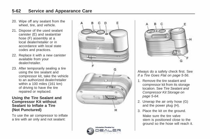
20. Wipe off any sealant from thewheel, tire, and vehicle.
21. Dispose of the used sealantcanister (E) and sealant/airhose (F) assembly at alocal dealer/retailer or inaccordance with local statecodes and practices.
22. Replace it with a new canisteravailable from yourdealer/retailer.
23. After temporarily sealing a tireusing the tire sealant andcompressor kit, take the vehicleto an authorized dealer/retailerwithin a 100 miles (161 km)of driving to have the tirerepaired or replaced.
Using the Tire Sealant andCompressor Kit withoutSealant to Inflate a Tire(Not Punctured)To use the air compressor to inflatea tire with air only and not sealant:
Always do a safety check first. SeeIf a Tire Goes Flat on page 5-56.
1. Remove the tire sealant andcompressor kit from its storagelocation. See Tire Sealant andCompressor Kit Storage onpage 5-64.
2. Unwrap the air only hose (G)and the power plug (H).
3. Place the kit on the ground.Make sure the tire valvestem is positioned close to theground so the hose will reach it.
5-62 Service and Appearance Care
Information Provided by:

4. Remove the tire valve stem capfrom the flat tire by turning itcounterclockwise.
5. Attach the air only hose (G) ontothe tire valve stem by turning itclockwise until it is tight.
6. Plug the power plug (H) into theaccessory power outlet in thevehicle. Unplug all items fromother accessory power outlets.See Accessory Power Outlet(s)on page 3-17.If the vehicle has an accessorypower outlet, do not use thecigarette lighter.If the vehicle only has a cigarettelighter, use the cigarette lighter.Do not pinch the power plugcord in the door or window.
7. Start the vehicle. The vehiclemust be running while usingthe air compressor.
8. Turn the selector switch (A)clockwise to the Air Only position.
9. Press the on/off (B) button to turnthe compressor on.The compressor will inflate thetire with air only.
10. Inflate the tire to therecommended inflation pressureusing the pressure gage (C).The recommended inflationpressure can be found on theTire and Loading Informationlabel. See Inflation - TirePressure on page 5-42.The pressure gage (C) mayread higher than the actual tirepressure while the compressoris on. Turn the compressor offto get an accurate reading.The compressor may be turnedon/off until the correct pressureis reached.
If you inflate the tire higherthan the recommended pressureyou can adjust the excesspressure by pressing thepressure deflation button (D),if equipped, until the properpressure reading is reached.This option is only functionalwhen using the air only hose (G).
11. Press the on/off button (B) toturn the tire sealant andcompressor kit off.Be careful while handling the tiresealant and compressor kit as itcould be warm after usage.
12. Unplug the power plug (H) fromthe accessory power outlet inthe vehicle.
13. Disconnect the air only hose (G)from the tire valve stem, byturning it counterclockwise, andreplace the tire valve stem cap.
Service and Appearance Care 5-63
Information Provided by:

14. Replace the air only hose (G)and the power plug (H) andcord back in its original location.
15. Place the equipment in theoriginal storage location in thevehicle.
The tire sealant and compressor kithas an accessory adapter locatedin a compartment on the bottomof its housing that may be used toinflate air mattresses, balls, etc.
Removal and Installation ofthe Sealant CanisterTo remove the sealant canister:
1. Unwrap the sealant hose.
2. Press the canister release button.
3. Pull up and remove the canister.
4. Replace with a new canisterwhich is available from yourdealer/retailer.
5. Push the new canister into place.
Tire Sealant andCompressor Kit StorageThe tire sealant and compressorkit is located in the storagecompartment on the driver side,at the rear of the vehicle.
1. Press down on the latch tab andpull the cover off to access thestorage compartment.
2. Press the two tabs on the quickrelease buckle to release the tiresealant and compressor kit strap.
3. Remove the sealant andcompressor kit from its tray.
To store the tire sealant andcompressor kit, reverse the steps.
5-64 Service and Appearance Care
Information Provided by:

Changing a Flat TireIf a tire goes flat, avoid further tireand wheel damage by driving slowlyto a level place. Turn on the hazardwarning flashers. See HazardWarning Flashers on page 3-5.
{ CAUTION
Changing a tire can be dangerous.The vehicle can slip off the jackand roll over or fall on you or otherpeople. You and they could bebadly injured or even killed. Finda level place to change your tire.To help prevent the vehicle frommoving:
1. Set the parking brake firmly.
2. Put the shift lever inP (Park).
(Continued)
CAUTION (Continued)
3. Turn off the engine and donot restart while the vehicleis raised.
4. Do not allow passengers toremain in the vehicle.
To be even more certain thevehicle will not move, you shouldput blocks at the front and rear ofthe tire farthest away from theone being changed. That wouldbe the tire, on the other side, atthe opposite end of the vehicle.
When the vehicle has a flat tire (B),use the following example as aguide to assist you in the placementof wheel blocks (A).
A. Wheel BlockB. Flat Tire
The following information explainshow to use the jack and changea tire.
Service and Appearance Care 5-65
Information Provided by:

Removing the Spare Tireand ToolsThe tools needed to remove thespare tire are located in the storagecompartment on the driver side,at the rear of the vehicle.
1. Open the jack storagecompartment by pulling on thelatch tab, located toward the rearof the vehicle, and pulling thecover off.
A. Tool BagB. Wing BoltC. Jack
2. Remove the wing bolt (B) byturning it counterclockwise
3. Push the jack (C) up out of theholding bracket.
4. Turn the jack on its side, with thebottom facing toward you.
5. Pull the jack straight out, bottomfirst.
The tools you will be using includethe jack (A) and lug wrench (B).
Removing the Spare TireThe compact spare tire is locatedunder the vehicle, in front of the rearbumper. See Compact Spare Tireon page 5-77 for more informationabout the compact spare.
A. Rear Convenience CenterB. Lug WrenchC. Storage Compartment Cap HoleD. Hoist ShaftE. Compact Spare TireF. RetainerG. Hoist Shaft Assembly
5-66 Service and Appearance Care
Information Provided by:

1. Open the storage compartmentdoor of the convenience centerthat is nearest the liftgate andremove the cap on the bottom ofthe storage compartment.
2. Open the carpet cutout that islocated through the hole of thestorage compartment.
3. Attach the lug wrench into thehoist shaft.
4. Turn the lug wrenchcounterclockwise to lowerthe spare tire to the ground.Continue turning the wrenchuntil the spare tire can be pulledout from under the vehicle.
5. Tilt the retainer and slip it throughthe wheel opening to remove thespare tire from the cable.
6. Turn the wrench clockwise toraise the cable back up afterremoving the spare tire.Do not store a full-size or a flatroad tire under the vehicle.See Storing a Flat or Spare Tireand Tools on page 5-74.
To continue changing the flat tire,see Removing the Flat Tire andInstalling the Spare Tire onpage 5-68.
If the spare tire will not lower, thesecondary latch could be engaged.
Service and Appearance Care 5-67
Information Provided by:
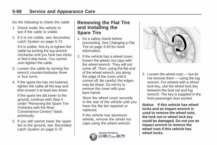
Do the following to check the cable:
1. Check under the vehicle tosee if the cable is visible.
2. If it is not visible, see SecondaryLatch System on page 5-72.If it is visible, first try to tighten thecable by turning the lug wrenchclockwise until you hear two clicksor feel it skip twice. You cannotover-tighten the cable.
3. Loosen the cable by turning thewrench counterclockwise threeor four turns.
4. If the spare tire has not lowered,tighten the cable all the way andthen loosen it at least two times.If the spare tire did lower to theground, continue with Step 5under “Removing the Spare Tire(Vehicles with the RearConvenience Center)” listedpreviously.
5. If you still cannot lower the sparetire to the ground, see SecondaryLatch System on page 5-72.
Removing the Flat Tireand Installing theSpare Tire1. Do a safety check before
proceeding. See Changing a FlatTire on page 5-65 for moreinformation.
2. If the vehicle has a wheel cover,loosen the plastic nut caps withthe wheel wrench. They will notcome off. Then, using the flat endof the wheel wrench, pry alongthe edge of the cover until itcomes off. Be careful; the edgesmay be sharp. Do not try toremove the cover with yourbare hands.Store the wheel cover securelyin the rear of the vehicle until youhave the flat tire repaired orreplaced.If the vehicle has aluminumwheels, remove the wheel nutcaps using the wheel wrench.
3. Loosen the wheel nuts — but donot remove them — using the lugwrench. For wheels with a wheellock key, use the wheel lock keybetween the lock nut and lugwrench. The key is supplied in thefront passenger door pocket.
Notice: If this vehicle has wheellocks and an impact wrench isused to remove the wheel nuts,the lock nut or wheel lock keycould be damaged. Do not use animpact wrench to remove thewheel nuts if this vehicle haswheel locks.
5-68 Service and Appearance Care
Information Provided by:

4. To identify the appropriate jackinglocation, find the triangle (A)about 12 inches (30.5 cm)from the front tire or (B) about10.5 inches (27 cm) from therear tire.The triangle is located near eachwheel on the vehicle’s exterior.
Notice: If a jack is used to raisethe vehicle without positioning itcorrectly, the vehicle could bedamaged. When raising thevehicle on a jack, avoid contactwith the rear axle control arms.
5. Do not raise the vehicle yet.Put the compact spare tirenear you.
{ CAUTION
Getting under a vehicle when it isjacked up is dangerous. If thevehicle slips off the jack, youcould be badly injured or killed.Never get under a vehicle when itis supported only by a jack.
{ CAUTION
Raising your vehicle with the jackimproperly positioned can damagethe vehicle and even make thevehicle fall. To help avoidpersonal injury and vehicledamage, be sure to fit the jack lifthead into the proper locationbefore raising the vehicle.
6. Attach the lug wrench to thejack, and turn the wrenchclockwise to raise the jack head3 inches (7.6 cm).
7. Place the jack under the vehicleas identified in Step 3. Raise thevehicle by turning the lug wrenchclockwise in the jack. Raise thevehicle far enough off the groundso that there is enough room forthe spare tire to fit under thewheel well.
8. Remove all the wheel nuts andthe flat tire.
Service and Appearance Care 5-69
Information Provided by:

9. Remove the plastic spare tireheat shield by pulling the rubberlatch. Store the plastic sparetire heat shield. See Storinga Flat or Spare Tire and Tools onpage 5-74 for more information.
{ CAUTION
Rust or dirt on a wheel, or on theparts to which it is fastened, canmake wheel nuts become looseafter time. The wheel could comeoff and cause an accident. Whenchanging a wheel, remove anyrust or dirt from places where thewheel attaches to the vehicle. Inan emergency, use a cloth or apaper towel to do this; but be sureto use a scraper or wire brushlater, if needed, to get all the rustor dirt off. See Changing a FlatTire on page 5-65.
{ CAUTION
Never use oil or grease onbolts or nuts because the nutsmight come loose. The vehicle’swheel could fall off, causing acrash.
10. Remove any rust or dirtfrom the wheel bolts,mounting surfaces, andspare wheel.
11. Place the spare tire on thewheel mounting surface.
5-70 Service and Appearance Care
Information Provided by:

12. Put the nuts on by hand byturning the clockwise untilthe wheel is held against themounting surface. Make surethe rounded end is towardthe wheel.
13. Lower the vehicle by attachingthe lug wrench to the jackand turning the wrenchcounterclockwise. Lowerthe jack completely.
{ CAUTION
Wheel nuts that are improperly orincorrectly tightened can causethe wheels to become loose orcome off. The wheel nuts shouldbe tightened with a torque wrenchto the proper torque specificationafter replacing. Follow the torque
(Continued)
CAUTION (Continued)
specification supplied by theaftermarket manufacturer whenusing accessory locking wheelnuts. See Capacities andSpecifications on page 5-92 fororiginal equipment wheel nuttorque specifications.
Notice: Improperly tightenedwheel nuts can lead to brakepulsation and rotor damage.To avoid expensive brake repairs,evenly tighten the wheel nuts inthe proper sequence and to theproper torque specification. SeeCapacities and Specifications onpage 5-92 for the wheel nut torquespecification.
14. Tighten the wheel nuts firmly ina crisscross sequence, asshown.
Notice: Wheel covers will not fiton your vehicle’s compact spare.If you try to put a wheel cover onthe compact spare, the cover orthe spare could be damaged.
Service and Appearance Care 5-71
Information Provided by:

Secondary Latch SystemThis vehicle has an underbodymounted tire hoist assembly thathas a secondary latch system. It isdesigned to stop the compact sparetire from suddenly falling off thevehicle if the cable holding the sparetire is damaged. For the secondarylatch to work, the tire must be stowedwith the valve stem pointing down.See Storing a Flat or Spare Tire andTools on page 5-74 for instructionson storing the spare tire correctly.
{ CAUTION
Before beginning this procedureread all the instructions. Failure toread and follow the instructionscould damage the hoist assemblyand you and others could gethurt. Read and follow theinstructions listed next.
To release the spare tire from thesecondary latch:
{ CAUTION
Someone standing too closeduring the procedure could beinjured by the jack. If the sparetire does not slide off the jackcompletely, make sure no one isbehind you or on either side ofyou as you pull the jack out fromunder the spare.
1. If the cable is not visible,start this procedure atStep 3.
2. Turn the lug wrenchcounterclockwise untilapproximately 6 inches (15 cm)of cable is exposed.
3. Attach the lug wrench to the jackand raise the jack at least10 turns.
4. Place the jack under the vehicle,ahead of the rear bumper.Position the center lift point ofthe jack under the center ofthe spare tire.
All-Wheel-Drive Vehicle shown
5-72 Service and Appearance Care
Information Provided by:

5. Turn the lug wrench clockwise toraise the jack until it lifts thesecondary latch spring.
6. Keep raising the jack until thespare tire stops moving upwardand is held firmly in place. Thislets you know that the secondarylatch has released and the sparetire is balancing on the jack.
7. Lower the jack by turning the lugwrench counterclockwise. Keeplowering the jack until thespare tire slides off the jack.
8. Disconnect the lug wrench fromthe jack and carefully removethe jack. Use one hand to pushagainst the spare tire while firmlypulling the jack out from under thespare tire with the other hand.
9. Tilt the retainer and slip itthrough the wheel opening whenthe spare tire has beencompletely lowered.
10. Turn the lug wrench clockwiseto raise the cable back up if thecable is hanging.
Have the hoist shaft assemblyinspected as soon as you can. Youwill not be able to store a sparetire using the hoist assembly until ithas been repaired or replaced.
Service and Appearance Care 5-73
Information Provided by:

Storing a Flat or SpareTire and ToolsStoring the Spare Tire
{ CAUTION
The underbody-mounted spare tireneeds to be stored with the valvestem pointing down. If the sparetire is stored with the valve stempointing upwards, the secondarylatch will not work properly andthe spare tire could loosen andsuddenly fall from the vehicle.If this happened when the vehiclewas being driven, the tire mightcontact a person or anothervehicle, causing injury anddamage to itself. Be sure theunderbody-mounted spare tireis stored with the valve stempointing down.
{ CAUTION
Storing a jack, a tire, or otherequipment in the passengercompartment of the vehicle couldcause injury. In a sudden stop orcollision, loose equipment couldstrike someone. Store all these inthe proper place.
To store the spare tire:
1. Lay the compact spare tire nearthe rear of the vehicle with thevalve stem down.
2. Reinstall the plastic spare tireheat shield on the compactspare tire.
3. Slide the cable retainer throughthe center of the wheel and startto raise the compact spare tire.Make sure the retainer is fullyseated across the underside ofthe wheel.
4. When the compact spare tire isalmost in the stored position,turn the tire so the valve istoward the rear of the vehicle.This position helps whenchecking the air pressure in thecompact spare tire.
5. Raise the tire fully against theunderside of the vehicle. Continueturning the lug wrench until youfeel more than two clicks. Thisindicates that the compact sparetire is secure and the cable istight. The spare tire hoist cannotbe overtightened.
5-74 Service and Appearance Care
Information Provided by:

6. Make sure the tire is storedsecurely. Push, pull (A), and thentry to turn (B) the tire. If the tiremoves, use the lug wrench totighten the cable.
Storing the Flat Tire1. Remove the cable package from
the jack storage area.
2. Remove the small center cap bytapping the back of the cap withthe extension of the shaft, if thevehicle has aluminum wheels.
3. Put the flat tire in the rear storagearea with the valve stem pointingtoward the rear of the vehicle.
4. Pull the cable (A) through thedoor striker (E), the center of thewheel (D), and the plastic sparetire heat shield (C), as shown.
5. Hook the cable onto the outsideportion of the liftgate hinges (B).
6. Hook the other end of the cableonto the outside portion of theliftgate hinge (A).
7. Pull on the cable to make sure itis secure.
Service and Appearance Care 5-75
Information Provided by:

8. Make sure the metal tube iscentered at the striker. Pushthe tube toward the front of thevehicle.
9. Close the liftgate and make sureit is latched properly.
Storing the Tools
A. Tool BagB. Wing BoltC. Jack
Put back all tools as they were storedin the jack storage compartment andput the compartment cover back on.
1. Ensure that the bottom of thejack is facing toward you.
2. Turn the jack (C) on its side andplace down on the holdingbracket.
3. Reinstall the wing bolt (B) byturning clockwise.
4. To replace the cover, line up thetab at the front of the cover withthe notch in the cover opening.Push the cover in place and makesure that the rear clips are in theslots and push the cover closed.
Store the center cap or the plasticbolt-on wheel covers until a full sizetire is put back on the vehicle. Whenyou replace the compact spare with afull-size tire, reinstall the bolt-onwheel covers or the center cap.Hand-tighten them over the wheelnuts, using the lug wrench.
5-76 Service and Appearance Care
Information Provided by:

Compact Spare Tire
{ CAUTION
Driving with more than onecompact spare tire at a time couldresult in loss of braking andhandling. This could lead to acrash and you or others could beinjured. Use only one compactspare tire at a time.
The compact spare tire, if thevehicle has one, was fully inflatedwhen the vehicle was new, however,it can lose air after a time. Checkthe inflation pressure regularly.It should be 60 psi (420 kPa).
After installing the compact spareon the vehicle, stop as soon aspossible and make sure the sparetire is correctly inflated. The compactspare is made to perform well atspeeds up to 65 mph (105 km/h) fordistances up to 3,000 miles(5 000 km), so you can finish yourtrip and have the full-size tirerepaired or replaced at yourconvenience. Of course, it is best toreplace the spare with a full-size tireas soon as possible. The spare tirewill last longer and be in good shapein case it is needed again.
Notice: When the compact spareis installed, do not take the vehiclethrough an automatic car washwith guide rails. The compactspare can get caught on the railswhich can damage the tire, wheeland other parts of the vehicle.
Do not use the compact spare onother vehicles.
And do not mix the compact sparetire or wheel with other wheelsor tires. They will not fit. Keep thespare tire and its wheel together.
The All-Wheel Drive (AWD) systemwill be automatically disabled whenyou use the compact spare. Torestore the AWD and preventexcessive wear on the clutch in yourAWD, replace the compact sparetire with a full-size tire as soon aspossible.
Notice: Tire chains will not fitthe compact spare. Using themcan damage the vehicle and candamage the chains too. Do not usetire chains on the compact spare.
Service and Appearance Care 5-77
Information Provided by:

Appearance Care
Interior CleaningThe vehicle’s interior will continueto look its best if it is cleaned often.Although not always visible, dustand dirt can accumulate on theupholstery. Dirt can damage carpet,fabric, leather, and plastic surfaces.Regular vacuuming is recommendedto remove particles from theupholstery. It is important to keepthe upholstery from becoming andremaining heavily soiled. Soilsshould be removed as quickly aspossible. The vehicle’s interior mayexperience extremes of heat thatcould cause stains to set rapidly.
Lighter colored interiors mayrequire more frequent cleaning.Use care because newspapers andgarments that transfer color to homefurnishings may also transfer color tothe vehicle’s interior.
When cleaning the vehicle’s interior,only use cleaners specificallydesigned for the surfaces beingcleaned. Permanent damage mayresult from using cleaners onsurfaces for which they were notintended. Use glass cleaner onlyon glass. Remove any accidentalover-spray from other surfacesimmediately. To prevent over-spray,apply cleaner directly to thecleaning cloth.
Notice: Using abrasive cleanerswhen cleaning glass surfaceson the vehicle, could scratch theglass and/or cause damage tothe rear window defogger. Whencleaning the glass on the vehicle,use only a soft cloth and glasscleaner.
Many cleaners contain solvents thatmay become concentrated in thevehicle’s breathing space. Beforeusing cleaners, read and adhere toall safety instructions on the label.While cleaning the vehicle’s interior,maintain adequate ventilation byopening the vehicle’s doors andwindows.
Dust may be removed from smallbuttons and knobs using a smallbrush with soft bristles.
Products that remove odors fromthe vehicle’s upholstery andclean the vehicle’s glass can beobtained from your dealer/retailer.
5-78 Service and Appearance Care
Information Provided by:

Do not clean the vehicle using:
• A knife or any other sharp objectto remove a soil from any interiorsurface.
• A stiff brush. It can cause damageto the vehicle’s interior surfaces.
• Heavy pressure or aggressiverubbing with a cleaning cloth. Useof heavy pressure can damagethe interior and does not improvethe effectiveness of soil removal.
• Laundry detergents ordishwashing soaps withdegreasers can leave residuethat streaks and attracts dirt. Forliquid cleaners, about 20 dropsper gallon (3.78 L) of water is agood guide. Use only mild,neutral-pH soaps.
• Too much cleaner that saturatesthe upholstery.
• Organic solvents such as naptha,alcohol, etc. that can damage thevehicle’s interior.
Fabric/CarpetUse a vacuum cleaner with asoft brush attachment frequentlyto remove dust and loose dirt.A canister vacuum with a beater barin the nozzle may only be used onfloor carpet and carpeted floor mats.For any soil, always try to remove itfirst with plain water or club soda.Before cleaning, gently remove asmuch of the soil as possible usingone of the following techniques:
• For liquids: gently blot theremaining soil with a paper towel.Allow the soil to absorb into thepaper towel until no more can beremoved.
• For solid dry soils: remove asmuch as possible and thenvacuum.
To clean:
1. Saturate a lint-free, clean whitecloth with water or club soda.
2. Wring the cloth to remove excessmoisture.
3. Start on the outside edge of thesoil and gently rub toward thecenter. Continue cleaning, usinga clean area of the cloth eachtime it becomes soiled.
4. Continue to gently rub the soiledarea until the cleaning clothremains clean.
5. If the soil is not completelyremoved, use a mild soapsolution and repeat the cleaningprocess that was used withplain water.
If any of the soil remains, acommercial fabric cleaner or spotlifter may be necessary. When acommercial upholstery cleaner orspot lifter is to be used, test a smallhidden area for colorfastness first.If the locally cleaned area gives anyimpression that a ring formation mayresult, clean the entire surface.
After the cleaning process has beencompleted, a paper towel can beused to blot excess moisture fromthe fabric or carpet.
Service and Appearance Care 5-79
Information Provided by:

LeatherA soft cloth dampened withwater can be used to remove dust.If a more thorough cleaning isnecessary, a soft cloth dampenedwith a mild soap solution can beused. Allow the leather to drynaturally. Do not use heat to dry.Never use steam to clean leather.Never use spot lifters or spotremovers on leather. Manycommercial leather cleanersand coatings that are sold topreserve and protect leather maypermanently change the appearanceand feel of the leather and are notrecommended. Do not use siliconeor wax-based products, or thosecontaining organic solvents toclean the vehicle’s interior becausethey can alter the appearance byincreasing the gloss in a non-uniformmanner. Never use shoe polish onleather.
Instrument Panel, Vinyl,and Other PlasticSurfacesA soft cloth dampened withwater may be used to remove dust.If a more thorough cleaning isnecessary, a clean soft clothdampened with a mild soap solutioncan be used to gently remove dustand dirt. Never use spot lifters orremovers on plastic surfaces. Manycommercial cleaners and coatingsthat are sold to preserve andprotect soft plastic surfaces maypermanently change the appearanceand feel of the interior and are notrecommended. Do not use siliconeor wax-based products, or thosecontaining organic solvents to cleanthe vehicle’s interior because theycan alter the appearance byincreasing the gloss in a non-uniformmanner.
Some commercial products mayincrease gloss on the instrumentpanel. The increase in glossmay cause annoying reflections inthe windshield and even makeit difficult to see through thewindshield under certain conditions.
Care of Safety BeltsKeep belts clean and dry.
{ CAUTION
Do not bleach or dye safety belts.It may severely weaken them.In a crash, they might not be ableto provide adequate protection.Clean safety belts only with mildsoap and lukewarm water.
5-80 Service and Appearance Care
Information Provided by:

WeatherstripsSilicone grease on weatherstrips willmake them last longer, seal better,and not stick or squeak. Applysilicone grease with a clean cloth.During very cold, damp weatherfrequent application may be required.See Recommended Fluids andLubricants on page 6-12.
Washing Your VehicleThe best way to preserve thevehicle’s finish is to keep it clean bywashing it often.
Notice: Certain cleaners containchemicals that can damage theemblems or nameplates on thevehicle. Check the cleaningproduct label. If it states that itshould not be used on plasticparts, do not use it on the vehicleor damage may occur and it wouldnot be covered by the warranty.
Do not wash the vehicle in directsunlight. Use a car washingsoap. Do not use cleaning agentsthat are petroleum based orthat contain acid or abrasives, asthey can damage the paint, metal orplastic on the vehicle. Approvedcleaning products can be obtainedfrom your dealer/retailer. Followall manufacturers’ directionsregarding correct product usage,necessary safety precautionsand appropriate disposal of anyvehicle care product.
Rinse the vehicle well, beforewashing and after to remove allcleaning agents completely. If theyare allowed to dry on the surface,they could stain.
Dry the finish with a soft, cleanchamois or an all-cotton towel toavoid surface scratches and waterspotting.
High pressure car washes maycause water to enter the vehicle.Avoid using high pressure washescloser than 12 inches (30 cm) tothe surface of the vehicle. Use ofpower washers exceeding 1,200 psi(8 274 kPa) can result in damage orremoval of paint and decals.
Cleaning ExteriorLamps/LensesUse only lukewarm or cold water, asoft cloth and a car washing soap toclean exterior lamps and lenses.Follow instructions under WashingYour Vehicle on page 5-81.
Finish CareOccasional waxing or mild polishingof the vehicle by hand may benecessary to remove residue fromthe paint finish. Approved cleaningproducts can be obtained from yourdealer/retailer.
Service and Appearance Care 5-81
Information Provided by:

If the vehicle has a basecoat/clearcoat paint finish, the clearcoatgives more depth and gloss to thecolored basecoat. Always use waxesand polishes that are non-abrasiveand made for a basecoat/clearcoatpaint finish.
Notice: Machine compoundingor aggressive polishing on abasecoat/clearcoat paint finishmay damage it. Use onlynon-abrasive waxes and polishesthat are made for a basecoat/clearcoat paint finish on thevehicle.
Foreign materials such as calciumchloride and other salts, ice meltingagents, road oil and tar, tree sap,bird droppings, chemicals fromindustrial chimneys, etc., candamage the vehicle’s finish if theyremain on painted surfaces. Washthe vehicle as soon as possible.
If necessary, use non-abrasivecleaners that are marked safe forpainted surfaces to remove foreignmatter.
Exterior painted surfaces aresubject to aging, weather andchemical fallout that can take theirtoll over a period of years. Tohelp keep the paint finish lookingnew, keep the vehicle garagedor covered whenever possible.
Protecting Exterior Bright MetalParts
Bright metal parts should be cleanedregularly to keep their luster.Washing with water is all that isusually needed. However, chromepolish may be used on chrome orstainless steel trim, if necessary.
Use special care with aluminum trim.To avoid damaging protective trim,never use auto or chrome polish,steam or caustic soap to cleanaluminum. A coating of wax, rubbedto high polish, is recommended for allbright metal parts.
Windshield, Backglass,and Wiper BladesClean the outside of the windshieldand backglass with glass cleaner.
Clean the rubber blades using alint free cloth or paper towel soakedwith windshield washer fluid or amild detergent. Wash the windshieldthoroughly when you clean theblades. Bugs, road grime, sapand a buildup of vehicle wash/waxtreatments may cause wiperstreaking. Replace the wiper bladesif they are worn or damaged.
Wipers can be damaged by:
• Extreme dusty conditions
• Sand and salt
• Heat and sun
• Snow and ice, without properremoval
5-82 Service and Appearance Care
Information Provided by:

Aluminum orChrome-Plated Wheelsand TrimThe vehicle may have eitheraluminum or chrome-plated wheels.
Keep the wheels clean using a softclean cloth with mild soap and water.Rinse with clean water. After rinsingthoroughly, dry with a soft cleantowel. A wax may then be applied.
Notice: Chrome wheels andother chrome trim may bedamaged if the vehicle is notwashed after driving on roadsthat have been sprayed withmagnesium, calcium or sodiumchloride. These chlorides areused on roads for conditionssuch as ice and dust. Alwayswash the vehicle’s chrome withsoap and water after exposure.
Notice: Using strong soaps,chemicals, abrasive polishes,cleaners, brushes, or cleanersthat contain acid on aluminumor chrome-plated wheels, could
damage the surface of thewheel(s). The repairs would not becovered by the vehicle warranty.Use only approved cleaners onaluminum or chrome-platedwheels.
The surface of these wheels issimilar to the painted surface of thevehicle. Do not use strong soaps,chemicals, abrasive polishes,abrasive cleaners, cleaners withacid, or abrasive cleaning brusheson them because they could damagethe surface. Do not use chromepolish on aluminum wheels.
Notice: Using chrome polish onaluminum wheels could damagethe wheels. The repairs wouldnot be covered by the vehiclewarranty. Use chrome polish onchrome wheels only.
Use chrome polish only onchrome-plated wheels, but avoidany painted surface of the wheel,and buff off immediately afterapplication.
Notice: Driving the vehiclethrough an automatic car washthat has silicone carbide tirecleaning brushes, could damagethe aluminum or chrome-platedwheels. The repairs would not becovered by the vehicle warranty.Never drive a vehicle that hasaluminum or chrome-platedwheels through an automatic carwash that uses silicone carbidetire cleaning brushes.
TiresTo clean the tires, use a stiff brushwith tire cleaner.
Notice: Using petroleum-basedtire dressing products on thevehicle may damage the paintfinish and/or tires. When applyinga tire dressing, always wipe offany overspray from all paintedsurfaces on the vehicle.
Service and Appearance Care 5-83
Information Provided by:

Sheet Metal DamageIf the vehicle is damaged andrequires sheet metal repair orreplacement, make sure the bodyrepair shop applies anti-corrosionmaterial to parts repaired or replacedto restore corrosion protection.
Original manufacturer replacementparts will provide the corrosionprotection while maintaining thevehicle warranty.
Finish DamageAny stone chips, fractures or deepscratches in the finish should berepaired right away. Bare metal willcorrode quickly and may develop intomajor repair expense.
Minor chips and scratches can berepaired with touch-up materialsavailable from your dealer/retailer.Larger areas of finish damage can becorrected in your dealer’s/retailer’sbody and paint shop.
Underbody MaintenanceChemicals used for ice and snowremoval and dust control can collecton the underbody. If these are notremoved, corrosion and rust candevelop on the underbody parts suchas fuel lines, frame, floor pan, andexhaust system even though theyhave corrosion protection.
At least every spring, flush thesematerials from the underbodywith plain water. Clean any areaswhere mud and debris can collect.Dirt packed in close areas ofthe frame should be loosened beforebeing flushed. Your dealer/retaileror an underbody car washingsystem can do this.
Chemical Paint SpottingSome weather and atmosphericconditions can create a chemicalfallout. Airborne pollutants can fallupon and attack painted surfaces onthe vehicle. This damage can taketwo forms: blotchy, ring-shapeddiscolorations, and small, irregulardark spots etched into the paintsurface.
Although no defect in the paint jobcauses this, we will repair, at nocharge to the owner, the surfacesof new vehicles damaged by thisfallout condition within 12 monthsor 12,000 miles (20 000 km) ofpurchase, whichever occurs first.
5-84 Service and Appearance Care
Information Provided by:

Vehicle Identification
Vehicle IdentificationNumber (VIN)
This is the legal identifier for thevehicle. It appears on a plate in thefront corner of the instrument panel,on the driver side. It can be seenthrough the windshield from outsidethe vehicle. The VIN also appears onthe Vehicle Certification and ServiceParts labels and the certificates oftitle and registration.
Engine IdentificationThe eighth character in the VIN is theengine code. This code helps identifythe vehicle’s engine, specifications,and replacement parts. See “EngineSpecifications” under Capacities andSpecifications on page 5-92 for thevehicle’s engine code.
Service PartsIdentification LabelThis label is on the inside of theglove box. It is very helpful if partsneed to be ordered. The labelhas the following information:
• Vehicle IdentificationNumber (VIN)
• Model designation
• Paint information
• Production options and specialequipment
Do not remove this label from thevehicle.
Electrical System
High Voltage Devices andWiring
{ CAUTION
Exposure to high voltage cancause shock, burns, and evendeath. The high voltage systemsin your vehicle can only beserviced by technicians withspecial training.
High voltage devices are identifiedby labels. Do not remove, open,take apart, or modify thesedevices. High voltage cable orwiring has orange covering. Do notprobe, tamper with, cut, or modifyhigh voltage cable or wiring.
Service and Appearance Care 5-85
Information Provided by:

Add-On ElectricalEquipmentNotice: Do not add anythingelectrical to the vehicle unless youcheck with your dealer/retailerfirst. Some electrical equipmentcan damage the vehicle and thedamage would not be covered bythe vehicle’s warranty. Someadd-on electrical equipment cankeep other components fromworking as they should.
Add-on equipment can drain thevehicle’s battery, even if the vehicleis not operating.
The vehicle has an airbag system.Before attempting to add anythingelectrical to the vehicle, seeServicing Your Airbag-EquippedVehicle on page 1-57.
Windshield Wiper FusesThe windshield wiper motor isprotected by a circuit breaker and afuse. If the motor overheats due toheavy snow or ice, the wiper will stopuntil the motor cools. If the overloadis caused by some electricalproblem, have it fixed.
Power Windows andOther Power OptionsCircuit breakers in the fuse blockprotect the power windows and otherpower accessories. When the currentload is too heavy, the circuit breakeropens and closes, protecting thecircuit until the problem is fixed orgoes away.
Fuses and CircuitBreakersThe wiring circuits in your vehicle areprotected from short circuits by acombination of fuses, circuit breakers
and fusible thermal links. This greatlyreduces the chance of fires causedby electrical problems.
Look at the silver-colored bandinside the fuse. If the band is brokenor melted, replace the fuse. Be sureyou replace a bad fuse with a newone of the identical size and rating.
Fuses of the same amperage can betemporarily borrowed from anotherfuse location, if a fuse goes out.Replace the fuse as soon asyou can.
Instrument Panel FuseBlockThe instrument panel fuse block islocated under the instrument panelon the passenger side of the vehicle.Pull down on the cover to access thefuse block.
5-86 Service and Appearance Care
Information Provided by:

Fuses UsageAIRBAG Airbag
AMP AmplifierBCK/UP/
STOPBack-upLamp/Stoplamp
BCM Body ControlModule
CNSTR/VENT Canister Vent
CTSY CourtesyDR/LCK Door Locks
DRL Daytime RunningLamps
DRL 2GMC HIDOnly/Rear FogLamps-China Only
DSPLY Display
FRT/WSW Front WindshieldWasher
HTD/COOLSEAT
Heated/CoolingSeats
HVAC Heating, Ventilationand Air Conditioning
Fuses UsageIADV/
PWR/LEDInadvertentPower LED
INFOTMNT Infotainment
LT/TRN/SIG Driver Side TurnSignal
MSM Memory SeatModule
PDM Power Mirrors,Liftgate Release
PWRMODE Power Mode
PWR/MIR Power MirrorsRDO Radio
REAR WPR Rear Wiper
RT/TRN/SIG Passenger SideTurn Signal
SPARE SpareSPARE Spare
STR/WHL/ILLUM
Steering WheelIllumination
Fuse Side
Service and Appearance Care 5-87
Information Provided by:

Relays UsageLT/PWR/
SEATDriver Side PowerSeat Relay
RT/PWR/SEAT
Passenger SidePower Seat Relay
Relays UsagePWR/
WNDWPower WindowsRelay
PWR/COLUMN
Power SteeringColumn Relay
L/GATE Liftgate RelayLCK Power Lock Relay
REAR/WSW Rear WindowWasher Relay
UNLCK Power Unlock Relay
DRL2 Daytime RunningLamps 2 Relay
LT/UNLCK Driver Side UnlockRelay
DRL Daytime RunningLamps Relay
SPARE Spare
FRT/WSW Front WindshieldWasher Relay
Underhood Fuse BlockThe underhood fuse block is locatedin the engine compartment, onthe passenger side of the vehicle.
Lift the cover for access to thefuse/relay block.
Notice: Spilling liquid on anyelectrical components on thevehicle may damage it. Alwayskeep the covers on any electricalcomponent.
To remove fuses, hold the end of thefuse between your thumb and indexfinger and pull straight out.
Relay Side
5-88 Service and Appearance Care
Information Provided by:

Fuses Usage
A/CCLUTCH
Air ConditioningClutch
ABS MTR Antilock BrakingSystem (ABS) Motor
AFS Adaptive ForwardLighting System
Fuses Usage
AIRBAG Airbag System
AUXPOWER Auxiliary Power
AUX VACPUMP
AuxiliaryVacuum Pump
Fuses Usage
AWD All-Wheel-DriveSystem
BATT 1 Battery 1
BATT 2 Battery 2
BATT 3 Battery 3
ECM Engine ControlModule
ECM 1 Engine ControlModule 1
EMISSION 1 Emission 1
EMISSION 2 Emission 2
EVENCOILS Even Injector Coils
FAN 1 Cooling Fan 1
FAN 2 Cooling Fan 2
FOG LAMP Fog Lamps
Service and Appearance Care 5-89
Information Provided by:

Fuses Usage
FSCM Fuel System ControlModule
HORN Horn
HTD WASH Heated WindshieldWasher Fluid
HTD MIR Heated OutsideRearview Mirror
HVACBLWR
Heating, Ventilationand Air ConditioningBlower
LT HIBEAM
Left High-BeamHeadlamp
LT LOBEAM
Left Low-BeamHeadlamp
LT PRK Left Parking Lamp
LT TRLRSTOP/TRN
Trailer LeftStoplamp and TurnSignal
Fuses Usage
ODDCOILS Odd Injector Coils
PCM IGN Powertrain ControlModule Ignition
PWRL/GATE Power Liftgate
PWROUTLET Power Outlet
REARCAMERA Rear Camera
RR APO Rear AccessoryPower Outlet
RR DEFOG Rear Defogger
RR HVAC Rear ClimateControl System
RT HIBEAM
Right High-BeamHeadlamp
RT LOBEAM
Right Low-BeamHeadlamp
Fuses Usage
RT PRK Right Parking Lamp
RT TRLRSTOP/TRN
Trailer RightStoplamp and TurnSignal
RVC SNSR Regulated VoltageControl Sensor
S/ROOF/SUNSHADE Sunroof
SPARE Spare
Stop Lamps(ChinaOnly)
Stop Lamps(China Only)
STRTR Starter
TCM TransmissionControl Module
TRANS Transmission
TRLRBCK/UP
Trailer Back-upLamps
5-90 Service and Appearance Care
Information Provided by:

Fuses Usage
TRLR BRK Trailer Brake
TRLR PRKLAMP
Trailer ParkingLamps
TRLR PWR Trailer Power
WPR/WSW WindshieldWiper/Washer
Relays UsageA/C
CMPRSRCLTCH
Air ConditioningCompressor Clutch
AUX VACPUMP
Auxiliary VacuumPump
CRNK Switched PowerFAN 1 Cooling Fan 1FAN 2 Cooling Fan 2FAN 3 Cooling Fan 3
FOG LAMP Fog Lamps
HI BEAM High-BeamHeadlamps
Relays Usage
HID/LOBEAM
High IntensityDischarge (HID)Low-BeamHeadlamps
HORN HornIGN Ignition Main
LT TRLRSTOP/TRN
Trailer LeftStoplamp and TurnSignal Lamp
PRK LAMP Park LampPWR/TRN Powertrain
RR DEFOG Rear WindowDefogger
RT TRLRSTOP/TRN
Trailer RightStoplamp and TurnSignal Lamp
Stop Lamps(ChinaOnly)
Stop Lamps(China Only)
TRLRBCK/UP
Trailer Back-upLamps
WPR Windshield Wiper
WPR HI Windshield WiperHigh Speed
Service and Appearance Care 5-91
Information Provided by:

Capacities and SpecificationsThe following approximate capacities are given in English and metric conversions. See Recommended Fluids andLubricants on page 6-12 for more information.
ApplicationCapacities
English Metric
Air Conditioning Refrigerant R134a
For the air conditioning system refrigerant chargeamount, see the refrigerant caution label locatedunder the hood. See your dealer/retailer for more
information.Cooling System 11.4 qt 10.8 LEngine Oil with Filter 5.5 qt 5.2 LFuel Tank 22.0 gal 83.3 LTransmission Fluid* 5.3 qt 5.0 LWheel Nut Torque 140 lb ft 190 Y
*See Automatic Transmission Fluid on page 5-16 for information on checking fluid level.All capacities are approximate. When adding, be sure to fill to the approximate level, as recommended in thismanual. Recheck fluid level after filling.
Engine SpecificationsEngine VIN Code Transmission Spark Plug Gap
3.6L V6 Engine D Automatic 0.043 in (1.10 mm)
5-92 Service and Appearance Care
Information Provided by:

MaintenanceSchedule
Maintenance ScheduleIntroduction ..........................6-1Maintenance Requirements .....6-1Your Vehicle and theEnvironment ........................6-1
Using the MaintenanceSchedule ............................6-2
Scheduled Maintenance .........6-3Additional Required Services ...6-6Maintenance Footnotes ..........6-7Owner Checks and Services ...6-9At Each Fuel Fill ...................6-9At Least Once a Month ..........6-9At Least Once a Year ..........6-10Recommended Fluids andLubricants .........................6-12
Maintenance ReplacementParts ................................6-14
Engine Drive Belt Routing .....6-15Maintenance Record ............6-16
MaintenanceSchedule
IntroductionImportant: Keep engine oil at theproper level and change asrecommended.
Have you purchased the GMProtection Plan? The Plansupplements the vehicle warranties.See the Warranty and OwnerAssistance booklet or yourdealer/retailer for details.
MaintenanceRequirementsNotice: Maintenance intervals,checks, inspections, replacementparts, and recommended fluidsand lubricants as prescribedin this manual are necessary tokeep this vehicle in good workingcondition. Any damage causedby failure to follow scheduledmaintenance might not becovered by the vehicle warranty.
Your Vehicle and theEnvironmentProper vehicle maintenance not onlyhelps to keep the vehicle in goodworking condition, but also helps theenvironment. All recommendedmaintenance is important. Impropervehicle maintenance can even affectthe quality of the air we breathe.
Maintenance Schedule 6-1
Information Provided by:

Improper fluid levels or the wrong tireinflation can increase the level ofemissions from the vehicle. To helpprotect the environment, and to keepthe vehicle in good condition, be sureto maintain the vehicle properly.
Using the MaintenanceScheduleWe want to help keep this vehicle ingood working condition. But we donot know exactly how you will drive it.You might drive very short distancesonly a few times a week. Or youmight drive long distances all thetime in very hot, dusty weather.You might use the vehicle in makingdeliveries. Or you might drive it towork, to do errands, or in manyother ways.
Because of all the differentways people use their vehicles,maintenance needs vary. You mightneed more frequent checks andreplacements. So please read thefollowing and note how you drive.
If you have any questions on how tokeep the vehicle in good condition,see your dealer/retailer.
This schedule is for vehicles that:
• carry passengers and cargowithin recommended limits on theTire and Loading Informationlabel. See Loading the Vehicle onpage 4-16.
• are driven on reasonable roadsurfaces within legal drivinglimits.
• use the recommended fuel. SeeGasoline Octane on page 5-5.
The services in ScheduledMaintenance on page 6-3 shouldbe performed when indicated.See Additional Required Serviceson page 6-6 and MaintenanceFootnotes on page 6-7 for furtherinformation.
{ CAUTION
Performing maintenance work ona vehicle can be dangerous. Intrying to do some jobs, you canbe seriously injured. Do your ownmaintenance work only if youhave the required know-how andthe proper tools and equipmentfor the job. If you have any doubt,see your dealer/retailer to have aqualified technician do the work.See Doing Your Own ServiceWork on page 5-4.
Some maintenance services canbe complex. So, unless you aretechnically qualified and have thenecessary equipment, have yourdealer/retailer do these jobs.
When you go to your dealer/retailerfor service, trained and supportedservice technicians will performthe work using genuine parts.
6-2 Maintenance Schedule
Information Provided by:

To purchase service information,see Service Publications OrderingInformation on page 7-15.
Owner Checks and Services onpage 6-9 tells what should bechecked, when to check it, and whatcan easily be done to help keepthe vehicle in good condition.
The proper replacement parts,fluids, and lubricants to use arelisted in Recommended Fluids andLubricants on page 6-12 andMaintenance Replacement Partson page 6-14. When the vehicle isserviced, make sure these are used.All parts should be replaced and allnecessary repairs done before youor anyone else drives the vehicle.We recommend the use of genuineparts from your dealer/retailer.
Scheduled MaintenanceWhen the CHANGE ENGINE OILSOON message displays, service isrequired for the vehicle. Have thevehicle serviced as soon as possiblewithin the next 600 miles (1 000 km).It is possible that, if driving under thebest conditions, the engine oil lifesystem might not indicate thatvehicle service is necessary for overa year. However, the engine oil andfilter must be changed at least oncea year and at this time the systemmust be reset. Your dealer/retailerhas trained service technicians whowill perform this work using genuineparts and reset the system.
If the engine oil life system is everreset accidentally, service the vehiclewithin 3,000 miles (5 000 km) sincethe last service. Remember to resetthe oil life system whenever the oilis changed. See Engine Oil LifeSystem on page 5-13 for informationon the Engine Oil Life System andresetting the system.
When the CHANGE ENGINEOIL SOON message appears,certain services, checks, andinspections are required. Requiredservices are described in thefollowing for “Maintenance I” and“Maintenance II.” Generally, it isrecommended that the first servicebe Maintenance I, the secondservice be Maintenance II, and thenalternate Maintenance I andMaintenance II thereafter. However,in some cases, Maintenance II maybe required more often.
Maintenance Schedule 6-3
Information Provided by:

Maintenance I — UseMaintenance I if the CHANGEENGINE OIL SOON messagedisplays within 10 months sincethe vehicle was purchased orMaintenance II was performed.
Maintenance II — UseMaintenance II if the previousservice performed wasMaintenance I. Always useMaintenance II whenever the
message displays 10 months ormore since the last service or if themessage has not come on at allfor one year.
Scheduled Maintenance
Service Maintenance I Maintenance II
Change engine oil and filter. See Engine Oil on page 5-11. Reset oil lifesystem. See Engine Oil Life System on page 5-13. An Emission ControlService.
• •
Visually check for any leaks or damage. See footnote (g). • •
Inspect engine air cleaner filter. If necessary, replace filter. See Engine AirCleaner/Filter on page 5-15. See footnote (l). •
Rotate tires and check inflation pressures and wear. See Tire Inspection andRotation on page 5-48 and “Tire Wear Inspection” in At Least Once a Month onpage 6-9.
• •
6-4 Maintenance Schedule
Information Provided by:

Scheduled Maintenance (cont’d)
Service Maintenance I Maintenance II
Inspect brake system. See footnote (a). • •
Check engine coolant and windshield washer fluid levels and add fluid asneeded. • •
Perform any needed additional services. See “Additional Required Services”in this section. • •
Inspect suspension and steering components. See footnote (b). •
Inspect engine cooling system. See footnote (c). •
Inspect wiper blades. See footnote (d). •
Inspect restraint system components. See footnote (e). •
Lubricate body components. See footnote (f). •
Inspect throttle system. See footnote (j). •
Maintenance Schedule 6-5
Information Provided by:

Additional Required ServicesThe following services should be performed at the first maintenance service (I or II) after the indicated miles(kilometers) shown for each item.
Additional Required Services
Service and Miles (Kilometers) 25,000(40 000)
50,000(80 000)
75,000(120 000)
100,000(160 000)
125,000(200 000)
150,000(240 000)
Inspect fuel system for damage or leaks. • • • • • •Inspect exhaust system for loose ordamaged components. • • • • • •
Replace engine air cleaner filter. SeeEngine Air Cleaner/Filter on page 5-15. • • •
Change automatic transmission fluid(severe service). See footnote (h). • • •
Change automatic transmission fluid(normal service). •
All-wheel-drive vehicles: Changetransfer case fluid (severe service).See footnote (m).
• • •
All-wheel-drive vehicles: Changetransfer case fluid (normal service). •
Replace spark plugs and inspect sparkplug wires. An Emission ControlService.
•
6-6 Maintenance Schedule
Information Provided by:

Additional Required Services (cont’d)
Service and Miles (Kilometers) 25,000(40 000)
50,000(80 000)
75,000(120 000)
100,000(160 000)
125,000(200 000)
150,000(240 000)
Engine cooling system service (orevery five years, whichever occursfirst). An Emission Control Service.See footnote (i).
•
Inspect engine accessory drive belt.An Emission Control Service.See footnote (k).
•
Maintenance Footnotes(a) Visually inspect brake lines andhoses for proper hook-up, binding,leaks, cracks, chafing, etc. Inspectdisc brake pads for wear and rotorsfor surface condition. Inspect otherbrake parts, including calipers,parking brake, etc. Check parkingbrake adjustment.
(b) Visually inspect front and rearsuspension and steering system fordamaged, loose, or missing parts orsigns of wear. Inspect power steeringlines and hoses for proper hook-up,binding, leaks, cracks, chafing, etc.
(c) Visually inspect hoses and havethem replaced if they are cracked,swollen, or deteriorated. Inspectall pipes, fittings and clamps; replacewith genuine parts as needed.To help ensure proper operation,a pressure test of the cooling systemand pressure cap and cleaningthe outside of the radiator andair conditioning condenser isrecommended at least oncea year.
(d) Inspect wiper blades for wear,cracking, or contamination. Cleanthe windshield and wiper blades,if contaminated. Replace wiperblades that are worn or damaged.See Windshield Wiper BladeReplacement on page 5-35 andWindshield, Backglass, and WiperBlades on page 5-82 for moreinformation.
Maintenance Schedule 6-7
Information Provided by:

(e) Make sure the safety beltreminder light and safety beltassemblies are working properly.Look for any other loose or damagedsafety belt system parts. If you seeanything that might keep a safetybelt system from doing its job, haveit repaired. Have any torn or frayedsafety belts replaced. Also seeChecking the Restraint Systemson page 1-59.
(f) Lubricate all key lock cylinders,hood latch assemblies, secondarylatches, pivots, spring anchor andrelease pawl, hood and door hinges,rear folding seats, and liftgatehinges. More frequent lubricationmay be required when exposed toa corrosive environment. Applyingsilicone grease on weatherstrips witha clean cloth will make them lastlonger, seal better, and not stickor squeak.
(g) A fluid loss in any vehicle systemcould indicate a problem. Have thesystem inspected and repaired andthe fluid level checked. Add fluid ifneeded.
(h) Change automatic transmissionfluid if the vehicle is mainly drivenunder one or more of theseconditions:− In heavy city traffic where the
outside temperature regularlyreaches 90°F (32°C) or higher.
− In hilly or mountainous terrain.− When doing frequent trailer
towing.− Uses such as found in taxi, police,
or delivery service.
(i) Drain, flush, and refill coolingsystem. This service can becomplex; you should have yourdealer/retailer perform this service.See Engine Coolant on page 5-17 forwhat to use. Inspect hoses. Cleanradiator, condenser, pressure cap,and filler neck. Pressure test thecooling system and pressure cap.
(j) Check system for interference orbinding and for damaged or missingparts. Replace parts as needed.Replace any components that havehigh effort or excessive wear. Do notlubricate accelerator or cruise controlcables.
(k) Visually inspect belt for fraying,excessive cracks, or obviousdamage. Replace belt if necessary.
(l) If driving regularly under dustyconditions, inspect the filter at eachengine oil change.
(m) Change transfer case fluid if thevehicle is mainly driven under oneor more of these conditions:− In heavy city traffic where the
outside temperature regularlyreaches 90°F (32°C) or higher.
− In hilly or mountainous terrain.− When doing frequent trailer
towing.− Uses such as found in taxi, police,
or delivery service.
6-8 Maintenance Schedule
Information Provided by:

Owner Checks andServicesThese owner checks and servicesshould be performed at the intervalsspecified to help ensure vehiclesafety, dependability, and emissioncontrol performance. Your dealer/retailer can assist with these checksand services.
Be sure any necessary repairs arecompleted at once. Whenever anyfluids or lubricants are added to thevehicle, make sure they are theproper ones, as shown inRecommended Fluids andLubricants on page 6-12.
At Each Fuel FillIt is important to perform theseunderhood checks at eachfuel fill.
Engine Oil Level Check
Notice: It is important to checkthe engine oil regularly andkeep it at the proper level. Failureto keep the engine oil at theproper level can cause damage tothe engine not covered by thevehicle warranty.
Check the engine oil level and addthe proper oil if necessary. SeeEngine Oil on page 5-11.
Engine Coolant Level CheckCheck the engine coolant leveland add DEX-COOL® coolantmixture if necessary. See EngineCoolant on page 5-17.
Windshield Washer FluidLevel CheckCheck the windshield washer fluidlevel in the windshield washerfluid reservoir and add the properfluid if necessary.
At Least Once a MonthTire Inflation CheckInspect the vehicle’s tires and makesure they are inflated to the correctpressures. Do not forget to checkthe spare tire, if the vehicle has one.See Inflation - Tire Pressure onpage 5-42. If the vehicle has a sparetire, check to make sure it is storedsecurely. See Changing a Flat Tireon page 5-65.
Tire Wear InspectionTire rotation may be required forhigh mileage highway drivers prior tothe Engine Oil Life System servicenotification. Check the tires forwear and, if necessary, rotate thetires. See Tire Inspection andRotation on page 5-48.
Maintenance Schedule 6-9
Information Provided by:

At Least Once a YearStarter Switch Check
{ CAUTION
When you are doing thisinspection, the vehicle could movesuddenly. If the vehicle moves,you or others could be injured.
1. Before starting this check, besure there is enough roomaround the vehicle.
2. Firmly apply both the parkingbrake and the regular brake.See Parking Brake on page 2-27.Do not use the acceleratorpedal, and be ready to turn offthe engine immediately if it starts.
3. Try to start the engine in eachgear. The vehicle should startonly in P (Park) or N (Neutral).If the vehicle starts in any otherposition, contact your dealer/retailer for service.
Automatic Transmission ShiftLock Control System Check
{ CAUTION
When you are doing thisinspection, the vehicle could movesuddenly. If the vehicle moves,you or others could be injured.
1. Before starting this check, besure there is enough roomaround the vehicle. It should beparked on a level surface.
2. Firmly apply the parking brake.See Parking Brake on page 2-27.Be ready to apply the regularbrake immediately if the vehiclebegins to move.
3. With the engine off, turn theignition to ON/RUN, but do notstart the engine. Without applyingthe regular brake, try to move theshift lever out of P (Park) withnormal effort. If the shift levermoves out of P (Park), contactyour dealer/retailer for service.
Ignition Transmission LockCheckWhile parked, and with the parkingbrake set, try to turn the ignitionto LOCK/OFF in each shift leverposition.
• The ignition should turn toLOCK/OFF only when the shiftlever is in P (Park).
• The ignition key should come outonly in LOCK/OFF.
Contact your dealer/retailer ifservice is required.
6-10 Maintenance Schedule
Information Provided by:
Parking Brake and AutomaticTransmission P (Park)Mechanism Check
{ CAUTION
When you are doing this check,the vehicle could begin to move.You or others could be injuredand property could be damaged.Make sure there is room in frontof the vehicle in case it begins toroll. Be ready to apply the regularbrake at once should the vehiclebegin to move.
Park on a fairly steep hill, with thevehicle facing downhill. Keepingyour foot on the regular brake, setthe parking brake.
• To check the parking brake’sholding ability: With the enginerunning and the transmission inN (Neutral), slowly remove footpressure from the regular brakepedal. Do this until the vehicle isheld by the parking brake only.
• To check the P (Park)mechanism’s holding ability: Withthe engine running, shift toP (Park). Then release theparking brake followed by theregular brake.
Contact your dealer/retailer ifservice is required.
Underbody Flushing ServiceAt least every spring, use plain waterto flush any corrosive materials fromthe underbody. Take care to cleanthoroughly any areas where mud andother debris can collect.
Tire Sealant andCompressor KitIf the vehicle has a Tire Sealant andCompressor Kit, check the sealantexpiration date printed on theinstruction label of the kit at leastonce a year. See your dealer/retailerfor a replacement canister.
Maintenance Schedule 6-11
Information Provided by:

Recommended Fluids and LubricantsFluids and lubricants identified below by name, part number, or specification can be obtained from yourdealer/retailer.
Usage Fluid/Lubricant
Engine Oil
Engine oil which meets GM Standard GM6094M and displays theAmerican Petroleum Institute Certified for Gasoline Engines starburstsymbol. To determine the proper viscosity for your vehicle’s engine, seeEngine Oil on page 5-11.
Engine Coolant 50/50 mixture of clean, drinkable water and use only DEX-COOL®
Coolant. See Engine Coolant on page 5-17.
Hydraulic Brake System DOT 3 Hydraulic Brake Fluid (GM Part No. U.S. 88862806,in Canada 88862807).
Windshield Washer Optikleen® Washer Solvent.
Power Steering System GM Power Steering Fluid (GM Part No. U.S. 89021184,in Canada 89021186).
6-12 Maintenance Schedule
Information Provided by:

Usage Fluid/Lubricant
Automatic Transmission DEXRON®-VI Automatic Transmission Fluid.
Key Lock Cylinders Multi-Purpose Lubricant, Superlube (GM Part No. U.S. 12346241,in Canada 10953474).
Carrier Assembly — Differential(Rear Drive Module) and Transfer
Case (Power Transfer Unit)
SAE 75W-90 Synthetic Axle Lubricant (GM Part No. U.S. 89021677in Canada 89021678) meeting GM Specification 9986115.
Hood Latch Assembly, SecondaryLatch, Pivots, Spring Anchor, and
Release Pawl
Lubriplate Lubricant Aerosol (GM Part No. U.S. 12346293,in Canada 992723) or lubricant meeting requirements of NLGI #2,Category LB or GC-LB.
Hood and Door Hinges and RearFolding Seat
Multi-Purpose Lubricant, Superlube (GM Part No. U.S. 12346241,in Canada 10953474).
Weatherstrip ConditioningWeatherstrip Lubricant (GM Part No. U.S. 3634770, in Canada 10953518)or Dielectric Silicone Grease (GM Part No. U.S. 12345579,in Canada 992887).
Maintenance Schedule 6-13
Information Provided by:
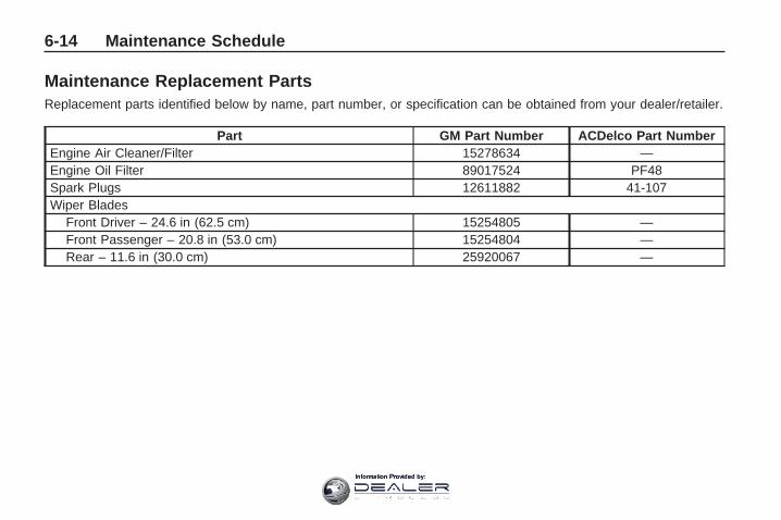
Maintenance Replacement PartsReplacement parts identified below by name, part number, or specification can be obtained from your dealer/retailer.
Part GM Part Number ACDelco Part NumberEngine Air Cleaner/Filter 15278634 —Engine Oil Filter 89017524 PF48Spark Plugs 12611882 41-107Wiper Blades
Front Driver – 24.6 in (62.5 cm) 15254805 —Front Passenger – 20.8 in (53.0 cm) 15254804 —Rear – 11.6 in (30.0 cm) 25920067 —
6-14 Maintenance Schedule
Information Provided by:

Engine Drive BeltRouting3.6L V6 Engine
Maintenance Schedule 6-15
Information Provided by:

Maintenance RecordAfter the scheduled services are performed, record the date, odometer reading, who performed the service, and thetype of services performed in the boxes provided. See Maintenance Requirements on page 6-1. Any additionalinformation from Owner Checks and Services on page 6-9 can be added on the following record pages. You shouldretain all maintenance receipts.
Maintenance Record
Date OdometerReading Serviced By Maintenance I or
Maintenance II Services Performed
6-16 Maintenance Schedule
Information Provided by:

Maintenance Record (cont’d)
Date OdometerReading Serviced By Maintenance I or
Maintenance II Services Performed
Maintenance Schedule 6-17
Information Provided by:
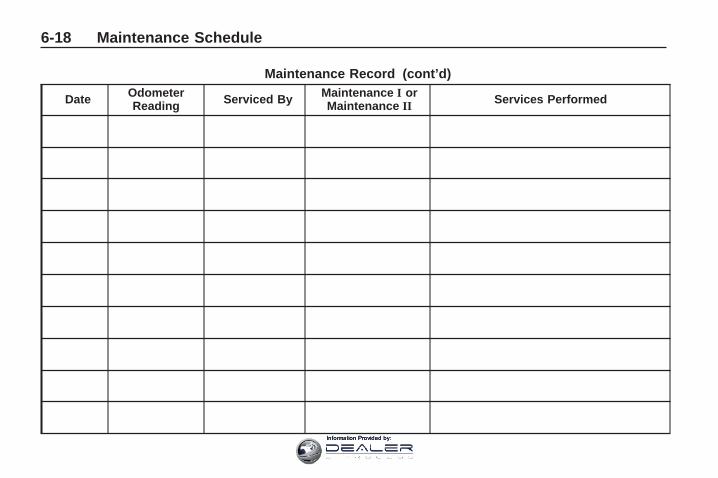
Maintenance Record (cont’d)
Date OdometerReading Serviced By Maintenance I or
Maintenance II Services Performed
6-18 Maintenance Schedule
Information Provided by:

CustomerAssistanceInformation
Customer Assistance andInformationCustomer SatisfactionProcedure ...........................7-1
Online Owner Center .............7-3Customer Assistance forText Telephone (TTY)Users .................................7-4
Customer Assistance Offices ...7-5GM Mobility ReimbursementProgram .............................7-6
Roadside AssistanceProgram .............................7-6
Scheduling ServiceAppointments ......................7-8
Courtesy Transportation .........7-9Collision Damage Repair ......7-10
Reporting Safety DefectsReporting Safety Defects tothe United StatesGovernment ......................7-14
Reporting Safety Defects tothe Canadian Government ...7-14
Reporting Safety Defects toGeneral Motors ..................7-14
Service PublicationsOrdering Information ...........7-15
Vehicle Data Recording andPrivacyVehicle Data Recording andPrivacy .............................7-16
Event Data Recorders ..........7-16OnStar® .............................7-17Navigation System ...............7-17Radio FrequencyIdentification (RFID) ............7-17
Customer Assistanceand Information
Customer SatisfactionProcedureYour satisfaction and goodwill areimportant to your dealer and toChevrolet. Normally, any concernswith the sales transaction or theoperation of the vehicle will beresolved by the dealer’s sales orservice departments. Sometimes,however, despite the best intentionsof all concerned, misunderstandingscan occur. If your concern has notbeen resolved to your satisfaction,the following steps should be taken:
STEP ONE: Discuss your concernwith a member of dealershipmanagement. Normally, concernscan be quickly resolved at that level.If the matter has already beenreviewed with the sales, service, orparts manager, contact the ownerof the dealership or the generalmanager.
Customer Assistance Information 7-1
Information Provided by:

STEP TWO: If after contacting amember of dealership management,it appears your concern cannot beresolved by the dealership withoutfurther help, in the U.S., call theChevrolet Customer AssistanceCenter at 1-800-222-1020. InCanada, call General Motors ofCanada Customer CommunicationCentre at 1-800-263-3777 (English),or 1-800-263-7854 (French).
We encourage you to call thetoll-free number in order to give yourinquiry prompt attention. Have thefollowing information available togive the Customer AssistanceRepresentative:
• Vehicle Identification Number(VIN). This is available from thevehicle registration or title, orthe plate at the top left of theinstrument panel and visiblethrough the windshield.
• Dealership name and location.
• Vehicle delivery date and presentmileage.
When contacting Chevrolet,remember that your concern willlikely be resolved at a dealer’sfacility. That is why we suggestfollowing Step One first.
STEP THREE — U.S. Owners: BothGeneral Motors and your dealer arecommitted to making sure you arecompletely satisfied with your newvehicle. However, if you continue toremain unsatisfied after following theprocedure outlined in Steps One andTwo, you can file with the BetterBusiness Bureau (BBB) Auto LineProgram to enforce your rights.
The BBB Auto Line Program is anout of court program administeredby the Council of Better BusinessBureaus to settle automotivedisputes regarding vehicle repairs orthe interpretation of the New VehicleLimited Warranty. Although you maybe required to resort to this informaldispute resolution program prior tofiling a court action, use of theprogram is free of charge and your
case will generally be heard within40 days. If you do not agree with thedecision given in your case, you mayreject it and proceed with any othervenue for relief available to you.
You may contact the BBB Auto LineProgram using the toll-free telephonenumber or write them at the followingaddress:
BBB Auto Line ProgramCouncil of Better BusinessBureaus, Inc.4200 Wilson BoulevardSuite 800Arlington, VA 22203-1838
Telephone: 1-800-955-5100dr.bbb.org/goauto
This program is available in all50 states and the District ofColumbia. Eligibility is limited byvehicle age, mileage, and otherfactors. General Motors reserves theright to change eligibility limitationsand/or discontinue its participationin this program.
7-2 Customer Assistance Information
Information Provided by:

STEP THREE — CanadianOwners: In the event that youdo not feel your concerns havebeen addressed after following theprocedure outlined in Steps 1 and 2,General Motors of Canada Limitedwants you to be aware of itsparticipation in a no-chargeMediation/Arbitration Program.General Motors of Canada Limitedhas committed to binding arbitrationof owner disputes involvingfactory-related vehicle serviceclaims. The program provides forthe review of the facts involved byan impartial third party arbiter, andmay include an informal hearingbefore the arbiter. The programis designed so that the entiredispute settlement process, fromthe time you file your complaintto the final decision, should becompleted in about 70 days.
We believe our impartial programoffers advantages over courts inmost jurisdictions because it isinformal, quick, and free of charge.
For further information concerningeligibility in the Canadian MotorVehicle Arbitration Plan (CAMVAP),call toll-free 1-800-207-0685, or callthe General Motors CustomerCommunication Centre,1-800-263-3777 (English),1-800-263-7854 (French), or write to:
The Mediation/Arbitration Programc/o Customer CommunicationCentreGeneral Motors of Canada LimitedMail Code: CA1-163-0051908 Colonel Sam DriveOshawa, Ontario L1H 8P7
Your inquiry should be accompaniedby the Vehicle IdentificationNumber (VIN).
Online Owner CenterOnline Owner Center (U.S.) —www.gmownercenter.com/chevroletInformation and services customizedfor your specific vehicle — all inone convenient place.
• Digital owner manual, warrantyinformation, and more
• Online service and maintenancerecords
• Find Chevrolet dealers forservice nationwide
• Exclusive privileges and offers
• Recall notices for your specificvehicle
• OnStar® and GM CardmemberServices Earnings summaries
Customer Assistance Information 7-3
Information Provided by:

Other Helpful Links:
Chevrolet — www.chevrolet.com
Chevrolet Merchandise —www.chevymall.com
Help Center — www.chevrolet.com/helpcenter
• FAQ
• Contact Us
My GM Canada(Canada) — www.gm.caMy GM Canada is apassword-protected section ofwww.gm.ca where you can saveinformation on GM vehicles, getpersonalized offers, and use handytools and forms with greater ease.
Here are a few of the valuabletools and services you will haveaccess to:
• My Showroom: Find and saveinformation on vehicles andcurrent offers in your area.
• My Dealers/Retailers: Savedetails such as address andphone number for each of yourpreferred GM dealers/retailers.
• My Driveway: Access quick linksto parts and service estimates,check trade-in values, or schedulea service appointment by addingthe vehicles you own to yourdriveway profile.
• My Preferences: Manage yourprofile and use tools and formswith greater ease.
To sign up, visit the My GM Canadasection within www.gm.ca.
Customer Assistance forText Telephone (TTY)UsersTo assist customers whoare deaf, hard of hearing, orspeech-impaired and who useText Telephones (TTYs), Chevrolethas TTY equipment available atits Customer Assistance Center.Any TTY user in the U.S. cancommunicate with Chevrolet bydialing: 1-800-833-CHEV (2438).(TTY users in Canada can dial1-800-263-3830.)
7-4 Customer Assistance Information
Information Provided by:
Customer AssistanceOfficesChevrolet encourages customersto call the toll-free number forassistance. However, if a customerwishes to write or e-mail Chevrolet,the letter should be addressed to:
United States — CustomerAssistanceChevrolet Motor DivisionChevrolet Customer AssistanceCenterP.O. Box 33170Detroit, MI 48232-5170
Chevrolet.com1-800-222-10201-800-833-2438 (For TextTelephone devices (TTYs))Roadside Assistance:1-800-CHEV-USA (243-8872)
From Puerto Rico:1-800-496-9992 (English)1-800-496-9993 (Spanish)
From U.S. Virgin Islands:1-800-496-9994
Canada — CustomerAssistanceGeneral Motors of Canada LimitedCustomer Communication Centre,CA1-163-0051908 Colonel Sam DriveOshawa, Ontario L1H 8P7
gmcanada.com1-800-263-3777 (English)1-800-263-7854 (French)1-800-263-3830 (For TextTelephone devices (TTYs))Roadside Assistance:1-800-268-6800
Overseas — CustomerAssistancePlease contact the local GeneralMotors Business Unit.
Mexico, Central America andCaribbean Islands/Countries(Except Puerto Rico and U.S.Virgin Islands) — CustomerAssistanceGeneral Motors de Mexico,S. de R.L. de C.V.Customer Assistance CenterPaseo de la Reforma # 2740Col. Lomas de BezaresC.P. 11910, Mexico, D.F.01-800-508-0000Long Distance: 011-52-53 29 0 800
Customer Assistance Information 7-5
Information Provided by:

GM MobilityReimbursement Program
This program, available to qualifiedapplicants, can reimburse youup to $1,000 of the cost of eligibleaftermarket adaptive equipmentrequired for your vehicle, such ashand controls or a wheelchair/scooter lift.
The offer is available for a verylimited period of time from the dateof vehicle purchase/lease. For moredetails, or to determine your vehicle’seligibility, visit gmmobility.com or callthe GM Mobility Assistance Center at1-800-323-9935. Text telephone(TTY) users, call 1-800-833-9935.
General Motors of Canadaalso has a Mobility Program.Call 1-800-GM-DRIVE (463-7483)for details. TTY users call1-800-263-3830.
Roadside AssistanceProgramFor U.S. purchased vehicles,call 1-800-CHEV-USA(1-800-243-8872); (Text telephone(TTY): 1-888-889-2438).
For Canadian purchased vehicles,call 1-800-268-6800.
Service is available 24 hours a day,365 days a year.
Calling for AssistanceWhen calling Roadside Assistance,have the following information ready:
• Your name, home address, andhome telephone number
• Telephone number of yourlocation
• Location of the vehicle
• Model, year, color, and licenseplate number of the vehicle
• Odometer reading, VehicleIdentification Number (VIN), anddelivery date of the vehicle
• Description of the problem
7-6 Customer Assistance Information
Information Provided by:

CoverageServices are provided up to 5 years/100,000 miles (160 000 km),whichever comes first.
In the U.S., anyone driving thevehicle is covered. In Canada, aperson driving the vehicle withoutpermission from the owner is notcovered.
Roadside Assistance is not a part ofthe New Vehicle Limited Warranty.Chevrolet and General Motors ofCanada Limited reserve the right tomake any changes or discontinuethe Roadside Assistance program atany time without notification.
Chevrolet and General Motors ofCanada Limited reserve the right tolimit services or payment to an owneror driver if they decide the claims aremade too often, or the same type ofclaim is made many times.
Services Provided• Emergency Fuel Delivery:
Delivery of enough fuel for thevehicle to get to the nearestservice station.
• Lock-Out Service: Service isprovided to unlock the vehicle ifyou are locked out. A remoteunlock may be available if youhave OnStar®. For securityreasons, the driver must presentidentification before this serviceis given.
• Emergency Tow From a PublicRoad or Highway: Tow to thenearest Chevrolet dealer forwarranty service, or if the vehiclewas in a crash and cannot bedriven. Assistance is also givenwhen the vehicle is stuck in thesand, mud, or snow.
• Flat Tire Change: Service isprovided to change a flat tirewith the spare tire. The spare tire,if equipped, must be in goodcondition and properly inflated.It is the owner’s responsibility forthe repair or replacement of thetire if it is not covered by thewarranty.
• Battery Jump Start: Service isprovided to jump start a deadbattery.
• Trip Interruption Benefitsand Assistance: If your trip isinterrupted due to a warrantyfailure, incidental expenses maybe reimbursed during the 5 years/100,000 miles (160 000 km)Powertrain warranty period. Itemsconsidered are hotel, meals, andrental car.
Customer Assistance Information 7-7
Information Provided by:

Services Not Included inRoadside Assistance• Impound towing caused by
violation of any laws.
• Legal fines.
• Mounting, dismounting orchanging of snow tires, chains,or other traction devices.
• Towing or services for vehiclesdriven on a non-public road orhighway.
Services Specific to CanadianPurchased Vehicles• Fuel delivery: Reimbursement
is approximately $5 Canadian.Diesel fuel delivery may berestricted. Propane and otherfuels are not provided throughthis service.
• Lock-Out Service: Vehicleregistration is required.
• Trip Routing Service: Detailedmaps of North America areprovided when requested eitherwith the most direct route or themost scenic route. There is alimit of six requests per year.Additional travel information isalso available. Allow three weeksfor delivery.
• Trip Interruption Benefitsand Assistance: Must be over250 kilometres from where yourtrip was started to qualify. GeneralMotors of Canada Limitedrequires pre-authorization,original detailed receipts, and acopy of the repair orders. Onceauthorization has been received,the Roadside Assistance advisorwill help you make arrangementsand explain how to receivepayment.
• Alternative Service: Ifassistance cannot be providedright away, the RoadsideAssistance advisor may give youpermission to get local emergencyroad service. You will receivepayment, up to $100, aftersending the original receipt toRoadside Assistance. Mechanicalfailures may be covered, howeverany cost for parts and labor forrepairs not covered by thewarranty are the ownerresponsibility.
Scheduling ServiceAppointmentsWhen your vehicle requires warrantyservice, contact your dealer/retailerand request an appointment. Byscheduling a service appointmentand advising your service consultantof your transportation needs, yourdealer/retailer can help minimizeyour inconvenience.
7-8 Customer Assistance Information
Information Provided by:

If your vehicle cannot bescheduled into the servicedepartment immediately, keepdriving it until it can be scheduledfor service, unless, of course, theproblem is safety-related. If it is,please call your dealership/retailer,let them know this, and ask forinstructions.
If the dealer/retailer requests you tobring the vehicle for service, youare urged to do so as early inthe work day as possible to allowfor the same day repair.
Courtesy TransportationTo enhance your ownershipexperience, we and our participatingdealers are proud to offer CourtesyTransportation, a customer supportprogram for vehicles with the Bumperto Bumper (Base Warranty Coverageperiod in Canada) and extendedpowertrain, and hybrid specificwarranty in both the U.S. andCanada.
Several courtesy transportationoptions are available to assistin reducing your inconveniencewhen warranty repairs are required.
Courtesy Transportation is not a partof the New Vehicle Limited Warranty.A separate booklet entitled “Warrantyand Owner Assistance Information”furnished with each new vehicleprovides detailed warranty coverageinformation.
Transportation OptionsWarranty service can generally becompleted while you wait. However,if you are unable to wait, GM helpsto minimize your inconvenience byproviding several transportationoptions. Depending on thecircumstances, your dealer canoffer you one of the following:
Shuttle Service
Shuttle service is the preferredmeans of offering CourtesyTransportation. Dealers may provideyou with shuttle service to get youto your destination with minimal
interruption of your daily schedule.This includes one-way or round tripshuttle service within reasonabletime and distance parameters of thedealer’s area.
Public Transportation or FuelReimbursement
If your vehicle requires overnightwarranty repairs, and publictransportation is used instead ofthe dealer’s shuttle service, theexpense must be supported byoriginal receipts and can only beup to the maximum amount allowedby GM for shuttle service. In addition,for U.S. customers, should youarrange transportation througha friend or relative, limitedreimbursement for reasonablefuel expenses may be available.Claim amounts should reflect actualcosts and be supported by originalreceipts. See your dealer forinformation regarding the allowanceamounts for reimbursement of fuel orother transportation costs.
Customer Assistance Information 7-9
Information Provided by:
Courtesy Rental Vehicle
Your dealer may arrange to provideyou with a courtesy rental vehicle orreimburse you for a rental vehiclethat you obtain if your vehicle is keptfor an overnight warranty repair.Rental reimbursement will be limitedand must be supported by originalreceipts. This requires that you signand complete a rental agreementand meet state/provincial, local,and rental vehicle providerrequirements. Requirements varyand may include minimum agerequirements, insurance coverage,credit card, etc. You are responsiblefor fuel usage charges and may alsobe responsible for taxes, levies,usage fees, excessive mileage, orrental usage beyond the completionof the repair.
It may not be possible to provide alike-vehicle as a courtesy rental.
Additional ProgramInformationAll program options, such asshuttle service, may not beavailable at every dealer. Pleasecontact your dealer for specificinformation about availability.All Courtesy Transportationarrangements will be administeredby appropriate dealer personnel.
General Motors reserves the rightto unilaterally modify, change ordiscontinue Courtesy Transportationat any time and to resolve allquestions of claim eligibility pursuantto the terms and conditionsdescribed herein at its solediscretion.
Collision Damage RepairIf your vehicle is involved in acollision and it is damaged, havethe damage repaired by a qualifiedtechnician using the properequipment and quality replacementparts. Poorly performed collisionrepairs diminish your vehicle’s resalevalue, and safety performance canbe compromised in subsequentcollisions.
Collision PartsGenuine GM Collision parts are newparts made with the same materialsand construction methods as theparts with which your vehicle wasoriginally built. Genuine GM Collisionparts are your best choice to ensurethat your vehicle’s designedappearance, durability, and safetyare preserved. The use of GenuineGM parts can help maintain yourGM New Vehicle Warranty.
7-10 Customer Assistance Information
Information Provided by:

Recycled original equipment partsmay also be used for repair. Theseparts are typically removed fromvehicles that were total losses inprior crashes. In most cases, theparts being recycled are fromundamaged sections of the vehicle.A recycled original equipment GMpart, may be an acceptable choiceto maintain your vehicle’s originallydesigned appearance and safetyperformance, however, the history ofthese parts is not known. Such partsare not covered by your GM NewVehicle Limited Warranty, and anyrelated failures are not covered bythat warranty.
Aftermarket collision parts arealso available. These are madeby companies other than GM andmay not have been tested for yourvehicle. As a result, these partsmay fit poorly, exhibit prematuredurability/corrosion problems,and may not perform properly
in subsequent collisions. Aftermarketparts are not covered by your GMNew Vehicle Limited Warranty, andany vehicle failure related to suchparts are not covered by thatwarranty.
Repair FacilityWe recommend that you choose acollision repair facility that meetsyour needs before you ever needcollision repairs. Your dealer/retailermay have a collision repair centerwith GM-trained technicians andstate of the art equipment, or beable to recommend a collisionrepair center that has GM-trainedtechnicians and comparableequipment.
Insuring Your VehicleProtect your investment in your GMvehicle with comprehensive andcollision insurance coverage. Thereare significant differences in thequality of coverage afforded byvarious insurance policy terms.
Many insurance policies providereduced protection to your GMvehicle by limiting compensationfor damage repairs by usingaftermarket collision parts. Someinsurance companies will notspecify aftermarket collision parts.When purchasing insurance, werecommend that you assure yourvehicle will be repaired with GMoriginal equipment collision parts.If such insurance coverage is notavailable from your current insurancecarrier, consider switching to anotherinsurance carrier.
If your vehicle is leased, the leasingcompany may require you to haveinsurance that assures repairs withGenuine GM Original EquipmentManufacturer (OEM) parts orGenuine Manufacturer replacementparts. Read your lease carefully, asyou may be charged at the end ofyour lease for poor quality repairs.
Customer Assistance Information 7-11
Information Provided by:

If a Crash OccursHere is what to do if you areinvolved in a crash.
• Check to make sure that youare all right. If you are uninjured,make sure that no one else inyour vehicle, or the other vehicle,is injured.
• If there has been an injury, callemergency services for help.Do not leave the scene of a crashuntil all matters have been takencare of. Move your vehicle only ifits position puts you in danger oryou are instructed to move it by apolice officer.
• Give only the necessary andrequested information to policeand other parties involved inthe crash. Do not discuss yourpersonal condition, mental frameof mind, or anything unrelated tothe crash. This will help guardagainst post-crash legal action.
• If you need roadside assistance,call GM Roadside Assistance.See Roadside AssistanceProgram on page 7-6 for moreinformation.
• If your vehicle cannot be driven,know where the towing servicewill be taking it. Get a card fromthe tow truck operator or writedown the driver’s name, theservice’s name, and the phonenumber.
• Remove any valuables from yourvehicle before it is towed away.Make sure this includes yourinsurance information andregistration if you keep theseitems in your vehicle.
• Gather the important informationyou will need from the otherdriver. Things like name, address,phone number, driver’s licensenumber, vehicle license plate,vehicle make, model and modelyear, Vehicle IdentificationNumber (VIN), insurancecompany and policy number,and a general description of thedamage to the other vehicle.
• If possible, call your insurancecompany from the scene ofthe crash. They will walk youthrough the information they willneed. If they ask for a policereport, phone or go to the policedepartment headquarters the nextday and you can get a copy of thereport for a nominal fee. In somestates/provinces with “no fault”insurance laws, a report may notbe necessary. This is especiallytrue if there are no injuries andboth vehicles are driveable.
7-12 Customer Assistance Information
Information Provided by:

• Choose a reputable collisionrepair facility for your vehicle.Whether you select a dealer/retailer or a private collision repairfacility to fix the damage, makesure you are comfortable withthem. Remember, you will have tofeel comfortable with their work fora long time.
• Once you have an estimate, readit carefully and make sure youunderstand what work will beperformed on your vehicle. If youhave a question, ask for anexplanation. Reputable shopswelcome this opportunity.
Managing the Vehicle DamageRepair ProcessIn the event that your vehiclerequires damage repairs, GMrecommends that you take an activerole in its repair. If you have apre-determined repair facility ofchoice, take your vehicle there, orhave it towed there. Specify to thefacility that any required replacementcollision parts be original equipmentparts, either new Genuine GM partsor recycled original GM parts.Remember, recycled parts will notbe covered by your GM vehiclewarranty.
Insurance pays the bill for the repair,but you must live with the repair.Depending on your policy limits, yourinsurance company may initially
value the repair using aftermarketparts. Discuss this with your repairprofessional, and insist on GenuineGM parts. Remember if your vehicleis leased you may be obligated tohave the vehicle repaired withGenuine GM parts, even if yourinsurance coverage does not pay thefull cost.
If another party’s insurance companyis paying for the repairs, you are notobligated to accept a repair valuationbased on that insurance company’scollision policy repair limits, as youhave no contractual limits with thatcompany. In such cases, you canhave control of the repair and partschoices as long as cost stays withinreasonable limits.
Customer Assistance Information 7-13
Information Provided by:

Reporting SafetyDefects
Reporting Safety Defectsto the United StatesGovernmentIf you believe that your vehiclehas a defect which could cause acrash or could cause injury ordeath, you should immediatelyinform the National HighwayTraffic Safety Administration(NHTSA) in addition to notifyingGeneral Motors.
If NHTSA receives similarcomplaints, it may open aninvestigation, and if it finds that asafety defect exists in a group ofvehicles, it may order a recall andremedy campaign. However,NHTSA cannot become involvedin individual problems betweenyou, your dealer/retailer, orGeneral Motors.
To contact NHTSA, you maycall the Vehicle Safety Hotlinetoll-free at 1-888-327-4236(TTY: 1-800-424-9153); go tosafercar.gov; or write to:Administrator, NHTSA1200 New Jersey Avenue, S.E.Washington D.C., 20590
You can also obtain otherinformation about motor vehiclesafety from safercar.gov.
Reporting Safety Defectsto the CanadianGovernmentIf you live in Canada, and youbelieve that your vehicle hasa safety defect, notify TransportCanada immediately, in addition tonotifying General Motors ofCanada Limited. Call them at1-800-333-0510 or write to:
Transport CanadaRoad Safety Branch2780 Sheffield RoadOttawa, Ontario K1B 3V9
Reporting Safety Defectsto General MotorsIn addition to notifying NHTSA (orTransport Canada) in a situation likethis, please notify General Motors.
Call 1-800-222-1020, or write:
Chevrolet Motor DivisionChevrolet CustomerAssistance CenterP.O. Box 33170Detroit, MI 48232-5170
In Canada, call 1-800-263-3777(English) or 1-800-263-7854(French), or write:
General Motors of Canada LimitedCustomer Communication Centre,CA1-163-0051908 Colonel Sam DriveOshawa, Ontario L1H 8P7
7-14 Customer Assistance Information
Information Provided by:

Service PublicationsOrdering InformationService ManualsService Manuals have the diagnosisand repair information on engines,transmission, axle suspension,brakes, electrical, steering, body, etc.
Service BulletinsService Bulletins give additionaltechnical service information neededto knowledgeably service GeneralMotors cars and trucks. Each bulletincontains instructions to assist inthe diagnosis and service of yourvehicle.
Owner InformationOwner publications are writtenspecifically for owners and intendedto provide basic operationalinformation about the vehicle.
The owner manual includes theMaintenance Schedule for allmodels.
In-Portfolio: Includes a Portfolio,Owner Manual, and WarrantyBooklet.
RETAIL SELL PRICE:$35.00 (U.S.) plus processing fee
Without Portfolio: OwnerManual only.
RETAIL SELL PRICE:$25.00 (U.S.) plus processing fee
Current and Past ModelOrder FormsTechnical Service Bulletins andManuals are available for currentand past model GM vehicles.To request an order form, specifyyear and model name of the vehicle.
ORDER TOLL FREE:1-800-551-4123 Monday-Friday8:00 AM - 6:00 PM Eastern Time
For Credit Card Orders Only(VISA-MasterCard-Discover), visitHelm, Inc. on the World WideWeb at: helminc.com
Or you can write to:
Helm, IncorporatedP.O. Box 07130Detroit, MI 48207
Prices are subject to changewithout notice and without incurringobligation. Allow ample time fordelivery.
Note to Canadian Customers: Alllisted prices are quoted in U.S.funds. Canadian residents are tomake checks payable in U.S. funds.
Customer Assistance Information 7-15
Information Provided by:

Vehicle DataRecording andPrivacyYour GM vehicle has a numberof sophisticated computers thatrecord information about thevehicle’s performance and howit is driven. For example, yourvehicle uses computer modules tomonitor and control engine andtransmission performance, to monitorthe conditions for airbag deploymentand deploy airbags in a crash and, ifso equipped, to provide antilockbraking to help the driver control thevehicle. These modules may storedata to help your dealer/retailertechnician service your vehicle.Some modules may also store dataabout how you operate the vehicle,such as rate of fuel consumption oraverage speed. These modules mayalso retain the owner’s personalpreferences, such as radio pre-sets,seat positions, and temperaturesettings.
Event Data RecordersThis vehicle has an Event DataRecorder (EDR). The main purposeof an EDR is to record, in certaincrash or near crash-like situations,such as an airbag deployment orhitting a road obstacle, data that willassist in understanding how avehicle’s systems performed. TheEDR is designed to record datarelated to vehicle dynamics andsafety systems for a short period oftime, typically 30 seconds or less.The EDR in this vehicle is designedto record such data as:
• How various systems in yourvehicle were operating
• Whether or not the driver andpassenger safety belts werebuckled/fastened
• How far, if at all, the driver waspressing the accelerator and/orbrake pedal
• How fast the vehicle was traveling
This data can help provide a betterunderstanding of the circumstancesin which crashes and injuries occur.
Important: EDR data is recordedby your vehicle only if a non-trivialcrash situation occurs; no data isrecorded by the EDR under normaldriving conditions and no personaldata (e.g., name, gender, age,and crash location) is recorded.However, other parties, such as lawenforcement, could combine theEDR data with the type of personallyidentifying data routinely acquiredduring a crash investigation.
To read data recorded by an EDR,special equipment is required, andaccess to the vehicle or the EDR isneeded. In addition to the vehiclemanufacturer, other parties, such aslaw enforcement, that have thespecial equipment, can read theinformation if they have access to thevehicle or the EDR.
7-16 Customer Assistance Information
Information Provided by:

GM will not access this data orshare it with others except: withthe consent of the vehicle owneror, if the vehicle is leased, with theconsent of the lessee; in response toan official request of police or similargovernment office; as part of GM’sdefense of litigation through thediscovery process; or, as requiredby law. Data that GM collects orreceives may also be used for GMresearch needs or may be madeavailable to others for researchpurposes, where a need is shownand the data is not tied to a specificvehicle or vehicle owner.
OnStar®
If your vehicle has OnStar and yousubscribe to the OnStar services,please refer to the OnStar Terms andConditions for information on datacollection and use. See also OnStar®
System on page 2-43 in this manualfor more information.
Navigation SystemIf your vehicle has a navigationsystem, use of the system mayresult in the storage of destinations,addresses, telephone numbers, andother trip information. Refer to thenavigation system operating manualfor information on stored data and fordeletion instructions.
Radio FrequencyIdentification (RFID)RFID technology is used in somevehicles for functions such as tirepressure monitoring and ignitionsystem security, as well as inconnection with conveniences suchas key fobs for remote door locking/unlocking and starting, and in-vehicletransmitters for garage door openers.RFID technology in GM vehiclesdoes not use or record personalinformation or link with any otherGM system containing personalinformation.
Customer Assistance Information 7-17
Information Provided by:
✍ NOTES
7-18 Customer Assistance Information
Information Provided by:

AAccessories and
Modifications ...................... 5-3Accessory Power ................. 2-22Accessory Power Outlets ...... 3-17Adding Equipment to Your
Airbag-Equipped Vehicle .... 1-58Additional Required Services,
Scheduled Maintenance ....... 6-6Additives, Fuel ...................... 5-5Add-On Electrical
Equipment ....................... 5-86Air Cleaner/Filter, Engine ....... 5-15Air Conditioning ................... 3-19Airbag
Readiness Light ................ 3-33Airbag System ..................... 1-46
Adding Equipment toYour Airbag-EquippedVehicle ........................ 1-58
How Does an AirbagRestrain? ..................... 1-51
Passenger SensingSystem ........................ 1-53
Servicing YourAirbag-EquippedVehicle ........................ 1-57
Airbag System (cont.)What Makes an Airbag
Inflate? ........................ 1-51What Will You See After
an Airbag Inflates? ........ 1-51When Should an Airbag
Inflate? ........................ 1-49Where Are the Airbags? ..... 1-48
AirbagsPassenger Status
Indicator ....................... 3-33All-Wheel-Drive (AWD)
System ............................. 4-7Antilock Brake System (ABS) ... 4-4
Warning Light ................... 3-37Appearance Care
Aluminum orChrome-Plated Wheels ... 5-83
Care of Safety Belts .......... 5-80Chemical Paint Spotting ..... 5-84Cleaning Exterior
Lamps/Lenses ............... 5-81Fabric/Carpet ................... 5-79Finish Care ...................... 5-81Finish Damage ................. 5-84Instrument Panel, Vinyl,
and Other PlasticSurfaces ...................... 5-80
Appearance Care (cont.)Interior Cleaning ............... 5-78Leather ........................... 5-80Sheet Metal Damage ........ 5-84Tires ............................... 5-83Underbody Maintenance .... 5-84Washing Your Vehicle ........ 5-81Weatherstrips ................... 5-81Windshield, Backglass,
and Wiper Blades .......... 5-82Assistance Program,
Roadside .......................... 7-6Audio System ...................... 3-73
Audio Steering WheelControls ..................... 3-125
Navigation/RadioSystem, seeNavigation Manual ....... 3-103
Setting the Clock .............. 3-74Audio System(s) .................. 3-75Audio Systems
Radio Reception ............. 3-126Rear Seat (RSA) ............. 3-123Theft-Deterrent Feature .... 3-125
Automatic TransmissionFluid ............................... 5-16Operation ........................ 2-24
INDEX i-1
Information Provided by:

BBattery ............................... 5-28
Electric PowerManagement ................. 3-15
Run-Down Protection ......... 3-16Belt Routing, Engine ............. 6-15Blind Spot Mirrors ................ 2-34Bluetooth® ......................... 3-103Brake
Emergencies ...................... 4-5Brake Fluid ......................... 5-25Brakes ............................... 5-25
Antilock ............................. 4-4Parking ........................... 2-27System Warning Light ....... 3-36
Braking ................................ 4-3Braking in Emergencies .......... 4-5Break-In, New Vehicle .......... 2-20Bulb Replacement ................ 5-34
Fog Lamp ........................ 3-13Halogen Bulbs .................. 5-33Headlamp Aiming .............. 5-33Headlamps ...................... 5-33Taillamps, Turn Signal,
Stoplamps andSidemarker Lamps ......... 5-33
Buying New Tires ................. 5-50
CCalibration .......................... 3-54California
Perchlorate MaterialsRequirements ................. 5-4
California Fuel ....................... 5-5California Proposition
65 Warning ........................ 5-4Camera, Rear Vision ............ 2-38Canadian Owners ..................... iiCapacities and
Specifications ................... 5-92Carbon Monoxide ................. 2-11
Engine Exhaust ................ 2-30Liftgate ............................ 2-10Winter Driving .................. 4-14
Care ofSafety Belts ..................... 5-80
CargoTie Downs ....................... 2-55
Cargo Cover ....................... 2-55Cargo Management System ... 2-55CD, MP3 .................... 3-92, 3-96Center Console Storage ........ 2-52Chains, Tire ........................ 5-55Charging System Light .......... 3-34
CheckEngine Lamp ................... 3-39
Checking Things Underthe Hood ........................... 5-9
Chemical Paint Spotting ........ 5-84Child Restraints
Infants and YoungChildren ....................... 1-29
Lower Anchors and Tethersfor Children .................. 1-35
Older Children .................. 1-27Securing a Child Restraint
in a Rear Seat Position .... 1-41Securing a Child Restraint
in the Right Front SeatPosition ....................... 1-43
Systems .......................... 1-32Where to Put the
Restraint ...................... 1-33Circuit Breakers ................... 5-86Cleaning
Aluminum or Chrome-PlatedWheels ........................ 5-83
Exterior Lamps/Lenses ...... 5-81Fabric/Carpet ................... 5-79Finish Care ...................... 5-81
i-2 INDEX
Information Provided by:

Cleaning (cont.)Instrument Panel, Vinyl,
and Other PlasticSurfaces ...................... 5-80
Interior ............................ 5-78Leather ........................... 5-80Tires ............................... 5-83Underbody Maintenance .... 5-84Washing Your Vehicle ........ 5-81Weatherstrips ................... 5-81Windshield, Backglass,
and Wiper Blades .......... 5-82Climate Control System ......... 3-19
Outlet Adjustment ............. 3-27Rear Air Conditioning and
Heating System ............. 3-28Rear Air Conditioning
and Heating System,Electronic ..................... 3-29
Climate Control SystemsDual Automatic ................. 3-22
Clock, Setting ...................... 3-74Collision Damage Repair ....... 7-10Compact Spare Tire ............. 5-77Compass ............................ 3-54Compressor Kit,
Tire Sealant ..................... 5-57
Content Theft-Deterrent ......... 2-16Control of a Vehicle ............... 4-3Convenience Net ................. 2-55Coolant
Engine ............................ 5-17Engine
Temperature Gage ......... 3-38Engine Temperature
Warning Light ............... 3-38Cooled Seats ........................ 1-5Cooling System ................... 5-17Courtesy Lamps ................... 3-14Courtesy Transportation .......... 7-9Cruise Control ....................... 3-9Cruise Control Light .............. 3-43Cupholders ......................... 2-52Customer Assistance .............. 7-4
Offices .............................. 7-5Text Telephone (TTY)
Users ............................ 7-4Customer Information
Service PublicationsOrdering Information ...... 7-15
Customer SatisfactionProcedure ......................... 7-1
DDamage Repair, Collision ...... 7-10Data Recorders
Event .............................. 7-16Daytime Running Lamps/
Automatic HeadlampSystem ........................... 3-12
Defensive Driving ................... 4-2Delayed Entry Lighting .......... 3-15Delayed Exit Lighting ............ 3-15Delayed Headlamps ............. 3-12Delayed Locking .................... 2-8DIC Compass ...................... 3-54Disc, MP3 ................... 3-92, 3-96Doing Your Own
Service Work ..................... 5-4Dome Lamp Override ........... 3-14Dome Lamps ....................... 3-14Door
Delayed Locking ................. 2-8Locks ............................... 2-8Power Door Locks .............. 2-8Programmable Automatic
Door Locks .................... 2-9Rear Door Security Locks .... 2-9
INDEX i-3
Information Provided by:

DriverSeat Height Adjuster ........... 1-3
Driver InformationCenter (DIC) .................... 3-44DIC Operation and
Displays ............... 3-45, 3-51DIC Vehicle
Customization ............... 3-65DIC Warnings and
Messages .................... 3-56Driving
At Night .......................... 4-10Before a Long Trip ............ 4-12Defensive .......................... 4-2Drunk ............................... 4-2Highway Hypnosis ............ 4-13Hill and Mountain Roads .... 4-13In Rain and on
Wet Roads ................... 4-11Loss of Control ................ 4-10Off-Road Recovery ............. 4-9Rocking Your Vehicle to
Get it Out .................... 4-16Winter ............................. 4-14
Driving for Better FuelEconomy ........................... 4-1
Dual Automatic ClimateControl System ................. 3-22
DVDRear Seat Entertainment
System ...................... 3-114
EEDR .................................. 7-16Electrical Equipment
Add-On Equipment ............ 5-86Electrical System
Fuses and CircuitBreakers ...................... 5-86
Instrument PanelFuse Block ................... 5-86
Power Windows and OtherPower Options .............. 5-86
Underhood Fuse Block ...... 5-88Windshield Wiper Fuses .... 5-86
Electronic ImmobilizerPASS-Key® III+ ................ 2-18
Electronic ImmobilizerOperationPASS-Key® III+ ................ 2-18
EngineAir Cleaner/Filter ............... 5-15Check and Service Engine
Soon Lamp .................. 3-39Compartment Overview ...... 5-10Coolant ........................... 5-17Coolant Heater ................. 2-23Coolant
Temperature Gage ......... 3-38Coolant Temperature
Warning Light ............... 3-38Cooling System ................ 5-17Drive Belt Routing ............. 6-15Exhaust ........................... 2-30Oil .................................. 5-11Oil Life System ................. 5-13Overheated Protection
Operating Mode ............ 5-23Overheating ..................... 5-22Starting ........................... 2-22
Entry Lighting ...................... 3-14Event Data Recorders .......... 7-16Extender, Safety Belt ............ 1-27Exterior Lamps .................... 3-11
i-4 INDEX
Information Provided by:

FFilter
Engine Air Cleaner ............ 5-15Finish Damage .................... 5-84Flashers, Hazard Warning ....... 3-5Flash-to-Pass ........................ 3-7Flat Tire .............................. 5-56Flat Tire, Changing ............... 5-65Flat Tire, Storing .................. 5-74Floor Mats .......................... 2-54Fluid
Automatic Transmission ..... 5-16Power Steering ................. 5-24Windshield Washer ........... 5-24
Fog LampFog ................................ 3-13
Fuel ..................................... 5-5Additives ........................... 5-5California Fuel ................... 5-5Economy Driving ................ 4-1Filling a Portable Fuel
Container ....................... 5-8Filling the Tank .................. 5-7Fuels in Foreign Countries ... 5-6Gage .............................. 3-43Gasoline Octane ................ 5-5Gasoline Specifications ........ 5-5
FusesFuses and Circuit
Breakers ...................... 5-86Instrument Panel Fuse
Block ........................... 5-86Underhood Fuse Block ...... 5-88Windshield Wiper .............. 5-86
GGage
Speedometer ................... 3-32Tachometer ...................... 3-32Voltmeter Gage ................ 3-35
GagesEngine Coolant
Temperature ................. 3-38Fuel ................................ 3-43
Garage Door Opener ............ 2-47Gasoline
Octane ............................. 5-5Specifications ..................... 5-5
Glove Box ........................... 2-52GM Mobility Reimbursement
Program ............................ 7-6
HHalogen Bulbs ..................... 5-33Hazard Warning Flashers ........ 3-5Head Restraints ..................... 1-2Headlamp
Aiming ............................ 5-33Headlamps
Bulb Replacement ............. 5-33Daytime Running Lamps/
Automatic HeadlampSystem ........................ 3-12
Delayed .......................... 3-12Exterior Lamps ................. 3-11Flash-to-Pass ..................... 3-7High/Low Beam Changer ..... 3-7
Heated Seats ........................ 1-5Heater ................................ 3-19
Engine Coolant ................. 2-23Height Adjuster, Driver Seat .... 1-3High Voltage Devices and
Wiring ............................. 5-85Highbeam On Light .............. 3-43Highway Hypnosis ................ 4-13Hill and Mountain Roads ....... 4-13
INDEX i-5
Information Provided by:

HoodChecking Things Under ....... 5-9Release ............................ 5-9
Horn .................................... 3-5How to Wear Safety Belts
Properly .......................... 1-17
IIgnition Positions .................. 2-21Infants and Young Children,
Restraints ........................ 1-29Inflation - Tire Pressure ......... 5-42Instrument Panel
Brightness ....................... 3-13Cluster ............................ 3-31Overview ........................... 3-4Storage Area .................... 2-52
Introduction ........................... 6-1
JJump Starting ...................... 5-29
KKeyless Entry, Remote
Operation .......................... 2-4Keyless Entry System ............ 2-3Keys .................................... 2-2
LLabeling, Tire Sidewall .......... 5-37Lamp
Malfunction Indicator ......... 3-39Lamps
Courtesy ......................... 3-14Dome ............................. 3-14Dome Lamp Override ........ 3-14Reading .......................... 3-15
Lap-Shoulder Belt ................ 1-22LATCH System for Child
Restraints ........................ 1-35Liftgate
Carbon Monoxide ............. 2-10Liftgate, Power .................... 2-11Lighting
Delayed Entry .................. 3-15Delayed Exit .................... 3-15Entry .............................. 3-14Parade Dimming ............... 3-15
LightsAirbag Readiness ............. 3-33Antilock Brake System
(ABS) Warning .............. 3-37Brake System Warning ...... 3-36Charging System .............. 3-34Cruise Control .................. 3-43Engine Coolant
Temperature Warning ..... 3-38Exterior Lamps ................. 3-11Flash-to-Pass ..................... 3-7Highbeam On ................... 3-43High/Low Beam Changer ..... 3-7Oil Pressure ..................... 3-42Passenger Airbag Status
Indicator ....................... 3-33Safety Belt Reminders ....... 3-32Security ........................... 3-43StabiliTrak® Indicator ......... 3-37Tire Pressure ................... 3-39Tow/Haul Mode ................ 3-43
Loading Your Vehicle ............ 4-16Locks
Delayed Locking ................. 2-8Door ................................. 2-8Lockout Protection .............. 2-9
i-6 INDEX
Information Provided by:

Locks (cont.)Power Door ....................... 2-8Programmable Automatic
Door Locks .................... 2-9Rear Door Security Locks .... 2-9
Loss of Control .................... 4-10Lower Anchors and Tethers
for Children ...................... 1-35Luggage Carrier ................... 2-54Lumbar
Manual Controls ................. 1-4Power Controls .................. 1-5
MMaintenance
Footnotes .......................... 6-7Maintenance Schedule
Additional RequiredServices ........................ 6-6
At Each Fuel Fill ................ 6-9At Least Once a Month ....... 6-9At Least Once a Year ....... 6-10Maintenance Record ......... 6-16Maintenance Replacement
Parts ........................... 6-14Maintenance Requirements ... 6-1
Maintenance Schedule (cont.)Owner Checks and
Services ........................ 6-9Recommended Fluids and
Lubricants .................... 6-12Scheduled Maintenance ....... 6-3Using ............................... 6-2Your Vehicle and the
Environment ................... 6-1Malfunction Indicator Lamp .... 3-39Manual Lumbar Controls ......... 1-4Manual Seats ........................ 1-3Memory Seat and Mirrors ....... 1-6Message
DIC Warnings andMessages .................... 3-56
MirrorsAutomatic Dimming
Rearview ...................... 2-31Blind Spot ....................... 2-34Manual Rearview Mirror ..... 2-31Outside Convex Mirror ....... 2-35Outside Heated Mirrors ...... 2-35Outside Power Foldaway
Mirrors ......................... 2-33Outside Power Mirrors ....... 2-32Park Tilt .......................... 2-35
MP3 ........................... 3-92, 3-96
NNavigation System, Privacy .... 7-17Navigation/Radio System,
see Navigation Manual .... 3-103Net
Convenience .................... 2-55New Vehicle Break-In ........... 2-20
OOdometer ........................... 3-32Off-Road
Recovery .......................... 4-9Oil
Engine ............................ 5-11Engine Oil Life System ...... 5-13Pressure Light .................. 3-42
Older Children, Restraints ...... 1-27Online Owner Center .............. 7-3OnStar, Privacy .................... 7-17OnStar® System, see
OnStar® Manual ............... 2-43Operation, Universal Home
Remote System ................ 2-47Outlet Adjustment ................. 3-27Outlets
Accessory Power .............. 3-17
INDEX i-7
Information Provided by:

OutsideConvex Mirror .................. 2-35Heated Mirrors ................. 2-35Power Foldaway Mirrors .... 2-33Power Mirrors .................. 2-32
Overheated Engine ProtectionOperating Mode ................ 5-23
Owner Checks and Services .... 6-9Owners, Canadian .................... ii
PPaint, Damage ..................... 5-84Parade Dimming .................. 3-15Park
Shifting Into ..................... 2-28Shifting Out of .................. 2-29
Park Aid ............................. 2-36Park Tilt Mirrors ................... 2-35Parking
Assist ............................. 2-36Over Things That Burn ...... 2-29
Parking Brake ...................... 2-27Passenger Airbag Status
Indicator .......................... 3-33Passenger Sensing System .... 1-53Passing ................................ 4-9PASS-Key® III+ Electronic
Immobilizer ...................... 2-18
PASS-Key® III+ ElectronicImmobilizer Operation ........ 2-18
Perchlorate MaterialsRequirements, California ...... 5-4
PhoneBluetooth® ..................... 3-103
PowerDoor Locks ........................ 2-8Electrical System .............. 5-86Liftgate ............................ 2-11Lumbar Controls ................. 1-5Outlet 115 Volt Alternating
Current ........................ 3-18Retained
Accessory (RAP) ........... 2-22Seat ................................. 1-4Steering Fluid ................... 5-24Windows ......................... 2-14
Pregnancy, UsingSafety Belts ..................... 1-26
Privacy ............................... 7-16Navigation System ............ 7-17OnStar ............................ 7-17Radio Frequency
Identification (RFID) ....... 7-17Programmable Automatic
Door Locks ........................ 2-9Proposition 65 Warning,
California .......................... 5-4
RRadio Frequency Identification
(RFID), Privacy ................. 7-17Radio(s) ............................. 3-75Radios
Navigation/RadioSystem, seeNavigation Manual ....... 3-103
Reception ...................... 3-126Setting the Clock .............. 3-74Theft-Deterrent ............... 3-125
Reading Lamps ................... 3-15Rear Air Conditioning and
Heating System ................ 3-28Rear Air Conditioning
and Heating Systemand Electronic ClimateControls .......................... 3-29
Rear Door Security Locks ....... 2-9Rear Seat Audio (RSA)
System .......................... 3-123Rear Seat Entertainment
System .......................... 3-114Rear Seat Audio (RSA) .... 3-123
Rear Seat Operation .............. 1-9Rear Vision Camera (RVC) .... 2-38Rear Window Washer/Wiper .... 3-9
i-8 INDEX
Information Provided by:

Rearview Mirror, AutomaticDimming .......................... 2-31
Rearview Mirrors .................. 2-31Reclining Seatbacks ............... 1-8Recommended Fluids and
Lubricants ........................ 6-12Recreational Vehicle Towing ... 4-21Reimbursement Program,
GM Mobility ....................... 7-6Remote Keyless Entry (RKE)
System ............................. 2-3Remote Keyless Entry (RKE)
System, Operation .............. 2-4Remote Vehicle Start ............. 2-6Removing the Flat Tire and
Installing the Spare Tire ..... 5-68Removing the Spare Tire
and Tools ........................ 5-66Replacement Bulbs .............. 5-34Replacement Parts,
Maintenance .................... 6-14Reporting Safety Defects to
General Motors ................ 7-14Reporting Safety Defects
to the CanadianGovernment ..................... 7-14
Reporting Safety Defectsto the United StatesGovernment ..................... 7-14
Restraint System CheckChecking the Restraint
Systems ....................... 1-59Replacing Restraint System
Parts After a Crash ........ 1-60Retained Accessory
Power (RAP) .................... 2-22Roadside Assistance
Program ............................ 7-6Rocking Your Vehicle to
Get it Out ........................ 4-16Roof
Sunroof ........................... 2-56Running the Vehicle While
Parked ............................ 2-30
SSafety Belt Reminders .......... 3-32Safety Belts
Care of ........................... 5-80Extender ......................... 1-27How to Wear Safety Belts
Properly ....................... 1-17Lap-Shoulder Belt ............. 1-22Safety Belts Are for
Everyone ..................... 1-14Use During Pregnancy ...... 1-26
Safety DefectsReporting to Canadian
Government .................. 7-14Reporting to
General Motors ............. 7-14Reporting to the United
States Government ........ 7-14Safety Warnings and Symbols .... iiiScheduled Maintenance .......... 6-3
Additional RequiredServices ........................ 6-6
Scheduling Appointments ........ 7-8Sealant Kit, Tire ................... 5-57Seats
Driver Seat HeightAdjuster ......................... 1-3
Head Restraints ................. 1-2Heated and Cooled Seats .... 1-5Heated Seats ..................... 1-5Manual Lumbar .................. 1-4Memory, Mirrors ................. 1-6Power Lumbar ................... 1-5Power Seats ...................... 1-4Rear Seat Operation ........... 1-9Reclining Seatbacks ............ 1-8Third Row Seat ................ 1-12
Second Row CenterConsole .......................... 2-53
INDEX i-9
Information Provided by:

Secondary Latch System ....... 5-72Securing a Child Restraint
Rear Seat Position ............ 1-41Right Front Seat Position ... 1-43
Security Light ...................... 3-43Service ................................ 5-3
Accessories andModifications .................. 5-3
Adding Equipment to theOutside of the Vehicle ..... 5-4
Doing Your Own Work ........ 5-4Engine Soon Lamp ........... 3-39Publications Ordering
Information ................... 7-15Scheduling Appointments ..... 7-8
Service Parts IdentificationLabel .............................. 5-85
Servicing YourAirbag-Equipped Vehicle .... 1-57
Setting the Clock ................. 3-74Sheet Metal Damage ............ 5-84Shifting
Out of Park ..................... 2-29Shifting Into Park ................. 2-28Signals, Turn and
Lane-Change ..................... 3-6
Spare TireCompact ......................... 5-77Installing .......................... 5-68Removing ........................ 5-66Storing ............................ 5-74
Specifications andCapacities ....................... 5-92
Speedometer ....................... 3-32StabiliTrak® Indicator Light ..... 3-37StabiliTrak® System ............... 4-5Start Vehicle, Remote ............. 2-6Starting the Engine .............. 2-22Steering ............................... 4-8Steering Wheel Controls,
Audio ............................ 3-125Steering Wheel, Tilt and
Telescopic ......................... 3-6Storage Areas
Cargo ManagementSystem ........................ 2-55
Center Console ................ 2-52Convenience Net .............. 2-55Cupholders ...................... 2-52Glove Box ....................... 2-52Instrument Panel .............. 2-52Luggage Carrier ............... 2-54Second Row Center
Console ....................... 2-53
Storing the Tire Sealant andCompressor Kit ................ 5-64
Stuck in Sand, Mud, Ice,or Snow .......................... 4-16
Sun Visors .......................... 2-16Sunroof .............................. 2-56
TTachometer ......................... 3-32Taillamps
Turn Signal, Stoplamps andSidemarker Lamps ......... 5-33
Telescopic Wheel ................... 3-6Text Telephone (TTY) Users .... 7-4Theft-Deterrent Feature ....... 3-125Theft-Deterrent Systems ........ 2-16
Content Theft-Deterrent ..... 2-16PASS-Key® III+ Electronic
Immobilizer ................... 2-18PASS-Key® III+ Electronic
Immobilizer Operation .... 2-18Third-Row Seats .................. 1-12Tilt Wheel ............................. 3-6Time, Setting ....................... 3-74Tire
Pressure Light .................. 3-39
i-10 INDEX
Information Provided by:

Tire Sealant andCompressor Kit ................ 5-64
Tires .................................. 5-36Aluminum or
Chrome-Plated Wheels,Cleaning ...................... 5-83
Buying New Tires ............. 5-50Chains ............................ 5-55Changing a Flat Tire ......... 5-65Cleaning .......................... 5-83Compact Spare ................ 5-77Different Size ................... 5-52If a Tire Goes Flat ............ 5-56Inflation - Tire Pressure ..... 5-42Inspection and Rotation ..... 5-48Installing the Spare Tire ..... 5-68Pressure Monitor
Operation ..................... 5-45Pressure Monitor System ... 5-43Removing the Flat Tire ...... 5-68Removing the Spare Tire
and Tools ..................... 5-66Sealant and
Compressor Kit ............. 5-57Secondary Latch System .... 5-72Sidewall Labeling .............. 5-37Storing a Flat or Spare Tire
and Tools ..................... 5-74
Tires (cont.)Terminology and
Definitions .................... 5-39Uniform Tire Quality
Grading ....................... 5-52Wheel Alignment and
Tire Balance ................. 5-54Wheel Replacement .......... 5-54When It Is Time for
New Tires .................... 5-50Tow/Haul Mode .................... 2-26Tow/Haul Mode Light ............ 3-43Towing
Recreational Vehicle .......... 4-21Towing a Trailer ................ 4-25Your Vehicle ..................... 4-21
TractionStabiliTrak® System ............ 4-5
TransmissionFluid, Automatic ................ 5-16
Transmission Operation,Automatic ........................ 2-24
Transportation, Courtesy ......... 7-9Turn and Lane-Change
Signals ............................. 3-6Turn Signal/Multifunction
Lever ................................ 3-6
UUltrasonic Rear Parking
Assist (URPA) .................. 2-36Uniform Tire Quality
Grading ........................... 5-52Universal Home Remote
System ........................... 2-47Operation ........................ 2-47
VVehicle
Control ............................. 4-3Loading ........................... 4-16Running While Parked ....... 2-30Symbols .............................. iii
Vehicle Customization, DIC .... 3-65Vehicle Data Recording and
Privacy ............................ 7-16Vehicle Data Recording,
Radio Frequency (RFID) .... 7-17Vehicle Identification
Number (VIN) ................... 5-85Service Parts Identification
Label ........................... 5-85Vehicle, Remote Start ............. 2-6
INDEX i-11
Information Provided by:

Ventilation Adjustment ........... 3-27Visors ................................. 2-16Voltage Devices, and Wiring ... 5-85Voltmeter Gage .................... 3-35
WWarning Lights, Gages, and
Indicators ........................ 3-30Warnings
DIC Warnings andMessages .................... 3-56
Hazard Warning Flashers .... 3-5Safety and Symbols .............. iii
WheelsAlignment and
Tire Balance ................. 5-54Different Size ................... 5-52Replacement .................... 5-54
When It Is Time forNew Tires ........................ 5-50
Where to Put theChild Restraint ................. 1-33
Windows ............................. 2-14Power ............................. 2-14
WindshieldBackglass, and Wiper
Blades, Cleaning ........... 5-82Washer ............................. 3-8Washer Fluid .................... 5-24Wiper Blade
Replacement ................ 5-35Wiper Fuses .................... 5-86Wipers .............................. 3-7
Winter Driving ...................... 4-14Wipers
Rear Washer ..................... 3-9Wiring, High Voltage
Devices ........................... 5-85
XXM Radio Messages ........... 3-102
YYour Vehicle and the
Environment ...................... 6-1
i-12 INDEX
Information Provided by: