2008 code digest - sawyer systems llc · classification of hazardous a. ... hazardous area...
TRANSCRIPT

Cooper Crouse-Hinds®
2008 Code Digest Article 500-516 of the National Electrical Code®
with product recommendations for use
in hazardous (classified) areas.


cCOOPER CROUSE-HINDS CODE DIGEST
Contents
PageIntroduction ................................................................................................................................................................................... 1
l. Classification of Hazardous A. The National Electrical Code® .................................................................................................. 2 Atmospheres B. Class I Atmospheric Hazards ..................................................................................................... 2 C. Class II Atmospheric Hazards ................................................................................................... 2 D. Class III Atmospheric Hazards .................................................................................................. 2 E. Evaluation of Hazardous Areas ................................................................................................. 2
II. Prevention of External Ignition and A. Enclosures .................................................................................................................................. 3 Explosion B. Purging/Pressurization Systems ................................................................................................ 3 C. Intrinsically Safe Equipment ..................................................................................................... 3
Ill. Equipment for Hazardous Areas A. Switchgear and Industrial Controls ........................................................................................... 4 B. Luminaires (Lighting Fixtures) ................................................................................................. 4 C. Motors and Generators .............................................................................................................. 5 D. Plugs and Receptacles ............................................................................................................... 6 E. Portable Devices ........................................................................................................................ 6
IV. Wiring Methods and Materials A. Conduit ...................................................................................................................................... 7 B. Seals for Conduit System .......................................................................................................... 7 C. Mineral-Insulated Cable ............................................................................................................ 8 D. Metal-Clad Cable ....................................................................................................................... 8 E. Tray Cable ................................................................................................................................. 8 F. Other Permitted Cables .............................................................................................................. 8 G. Cable Sealing ............................................................................................................................. 8 H. Nonmetallic Conduit ................................................................................................................. 8
V. Maintenance Principles A. Electrical Circuits ...................................................................................................................... 9 B. Assembly or Disassembly of Enclosures .................................................................................. 9 C. Cover Attachment Screws .......................................................................................................... 9 D. Cleaning and Lubrication .......................................................................................................... 9 E. Shaft and Bearing Surfaces........................................................................................................ 9 F. Corrosive Locations ................................................................................................................... 9 G. Portable Equipment ................................................................................................................... 9 H. Overall Safety ............................................................................................................................ 9 I. Plug-in Replacement Units ........................................................................................................ 9 J. Maintenance .............................................................................................................................. 9
VI. Selected Articles from the National 500 Hazardous (Classified) Locations ............................................................................................ 10 Electrical Code® 2008 501 Class I Locations ..................................................................................................................... 18 502 Class II Locations .................................................................................................................... 36 503 Class III Locations ................................................................................................................... 45 504 Intrinsically Safe Systems ....................................................................................................... 49 505 Class I, Zone 0, 1 and 2 Locations .......................................................................................... 51 506 Zone 20, 21, and 22 Locations for Combustible Dusts, Ignitible Fibers/Flyings .................... 67 510 Hazardous (Classified) Locations – Specific ........................................................................... 72 511 Commercial Garages, Repair and Storage ............................................................................... 73 513 Aircraft Hangars ...................................................................................................................... 76 514 Motor Fuel Dispensing Facilities ............................................................................................ 78 515 Bulk Storage Plants ................................................................................................................. 82 516 Spray Application, Dipping and Coating Processes ................................................................ 87
Appendices I & II Hazardous Substances Used in Business and Industry .......................................................93-97 I Table I – Gases and Vapors – Hazardous Substances Used in Business and Industry ............ 93 II Table II – Dusts – Hazardous Substances Used in Business and Industry .............................. 96 III Selection of Seals and Drains .................................................................................................. 98 IV Installation Diagram for Sealing ........................................................................................... 102 V Diagram for Class I, Zone 1 Power and Lighting Installation ............................................... 103 VI Diagram for Class I, Division 1 Lighting Installation ........................................................... 104 VII Diagram for Class I, Division 1 Power Installation ............................................................... 105 VIII Diagram for Class I, Division 2 Power and Lighting Installation ......................................... 106 IX Diagram for Class II Lighting Installation ............................................................................ 107 X Diagram for Class II Power Installation ................................................................................ 108 XI “Quick Selector” Electrical Equipment for Hazardous Locations ........................................ 109
Hazardous Area Reference Global reference guide for potentially explosive atmospheres and hazardous locations ................. 110
Cooper Crouse-Hinds Code Digest


1COOPER CROUSE-HINDS CODE DIGEST
ForewordCooper Crouse-Hinds has revised its Code Digest for 2008 to meet the needs of design personnel for a ready reference to equipment and installation ideas in hazardous locations. Selected Articles from the National Electrical Code® have been explained with diagrams and photographs of electrical hardware taken from our Cooper Crouse-Hinds Product Catalog. Exhaustive laboratory testing and extensive research, development and field experience have proven that these items meet or exceed the requirements set forth by the National Electrical Code and Underwriters Laboratories Inc.®
This latest revision to the series of Cooper Crouse-Hinds service-oriented bulletins reflects the most recent changes in the National Electrical Code in Articles 500 through 516. Reproduction of these Articles has been made with the permission of the National Fire Protection Association.
Diagrams of recommended power and lighting installations have been included in Appendices V, VI, VII, VIII, IX and X to assist engineers involved in the design of these systems for hazardous locations. A “Quick-Selector” Guide for electrical equipment used for Class I, Class II and Class III installations is included in Appendix XI. Tables included are those of most frequent applicability and usage. Photographs of actual application of Cooper Crouse-Hinds products for a variety of environments have been added for clarity and specific reference.
We sincerely hope that this Digest will be of value to you. Feel free to call on your Cooper Crouse-Hinds representative for personal assistance in your installation planning at any time.
A. The National Electrical Code and Underwriters Laboratories Inc.
The NEC is a product of the National Fire Protection Association. It is considered the definitive classification tool and contains explanatory data about flammable gases and combustible dusts as it may apply to storage areas, garages, gasoline stations and other facilities where flammable or combustible materials are found. Specific installation practices have been set up for heavier-than-air vapors. In the case of hydrogen or other gas which has a low vapor density and is used indoors, the most hazardous concentrations are likely to be in the upper portion of the room.
Many states, municipalities and public service companies use the NEC as a requirement for their inspectors.
Underwriters Laboratories Inc. (UL) is an independent organization testing for public safety. Its function is to determine whether or not devices and equipment submitted to it are safe and can be used in the NEC category for which they were designed. To do this, it maintains extensive laboratory and testing facilities.
UL’s function does not include actual enforcement of the National Electrical Code. However, as previously indicated, inspection authorities use UL’s listing as criteria in carrying out their inspections of hazardous areas.
B. Combustion Principles.Three basic conditions must be satisfied for a fire or explosion to occur:
1. A flammable liquid, vapor or combustible dust must be present in sufficient quantity.
2. The flammable liquid, vapor or combustible dust must be mixed with air or oxygen in the proportions required to produce an explosive mixture.
3. A source of energy must be applied to the explosive mixture.
In applying these principles, the quantity of the flammable liquid or vapor that may be liberated and its physical characteristics must be recognized.
Vapors from flammable liquids also have a natural tendency to disperse into the atmosphere, and rapidly become diluted to concentrations below the lower flammable limit, particularly when there is natural or mechanical ventilation.
The possibility that the gas concentration may be above the upper flammable limit does not afford any degree of safety, as the concentration must first pass through the flammable range to reach the upper flammable limit.
C. Sources of Ignition.A source of energy is all that is needed to touch off an explosion when flammable gases or combustible dusts are mixed in the proper proportion with air.
One prime source of energy is electricity. Equipment such as switches, circuit breakers, motor starters, pushbutton stations, or plugs and receptacles, can produce arcs or sparks in normal operation when contacts are opened and closed. This could easily cause ignition.
Other hazards are devices that produce heat, such as luminaires and motors. Here surface temperatures may exceed the safe limits of many flammable atmospheres.
Finally, many parts of the electrical system can become potential sources of ignition in the event of insulation failure. This group would include wiring (particularly splices in the wiring), transformers, impedance coils, solenoids, and other low-temperature devices without make-or-break contacts.
Non-electrical hazards such as sparking metal can also easily cause ignition. A hammer, file or other tool that is dropped on masonry or on a ferrous surface is thus a hazard unless the tool is made of non-sparking material. For this reason, portable electrical equipment is usually made from aluminum or other material that will not produce sparks if the equipment is dropped.
Electrical safety, therefore, is of crucial importance. The electrical installation must prevent accidental ignition of flammable liquids, vapors and dusts released to the atmosphere. In addition, since much of this equipment is used outdoors or in corrosive atmospheres, the material and finish must be such that maintenance costs and shutdowns are minimized.
National Electrical Code®, NEC® symbol and NEC® are Registered Trademarks of the National Fire Protection Association, Inc., Quincy, MA. 02269
Introduction

2 COOPER CROUSE-HINDS CODE DIGEST
Division 2 switchrack
A. The National Electrical CodeThe National Electrical Code, widely used for classification purposes, divides atmospheric explosion hazards into three broad classes that are summarized below. However, it must be understood that considerable skill and judgment must be applied when deciding to what degree an area contains hazardous concentrations of vapors, combustible dusts or easily ignitible fibers and flyings. Many factors, such as temperature, barometric pressure, quantity of release, humidity, ventilation, distance from the vapor source, etc., must be considered. When information on all factors concerned is properly evaluated, a consistent classification for the selection and location of electrical equipment can be developed. For further information on classification of areas see NFPA 497-2004 Recommended Practice for the Classification of Flammable Liquids, Gases or Vapors and of Hazardous (Classified) Locations for Electrical Installations in Chemical Process Areas and NFPA 499-2004, Recommended Practice for the Classification of Combustible Dusts and of Hazardous (Classified) Locations for Electrical Installations in Chemical Process Areas.
Appendices I and II list flammable gases and combustible dusts which have been classified by NFPA along with their ignition temperatures and other data.
B. Class I Atmospheric Hazards.Class I atmospheric hazards are divided not only into the four groups, A, B, C, and D shown in Appendix I, but also into two divisions. Division 1 covers locations where flammable gases or vapors may exist under normal operating conditions, under frequent repair or maintenance operations, or where breakdown or faulty operation of process equipment might also cause simultaneous failure of electrical equipment.
Division 2 covers locations where flammable gases, vapors or volatile liquids are handled either in a closed system, or confined within suitable enclosures, or where hazardous concentrations are normally prevented by positive mechanical ventilation. Areas adjacent to Division 1 locations, into which gases might occasionally flow, would also be Division 2.
The National Electrical Code contains an alternate “zone classification” system. For additional information refer to Article 505, beginning on page 51.
C. Class II Atmospheric Hazards.Class II atmospheric hazards cover three groups of combustible dusts, summarized in Appendix II. The groups are based on the type of material: Group E metallic, Group F carbonaceous, or Group G organic. Whether an area is Division 1 or 2 depends on the quantity of dust present, except that for Group E there is only Division 1.
D. Class III Atmospheric Hazards.Class III atmospheric hazards cover locations where combustible fibers/flyings are present but not likely to be in suspension in air in quantities sufficient to produce ignitible mixtures. Division 1 is where they are manufactured and Division 2 is where they are stored.
E. Evaluation of Hazardous Areas.Each area that contains gases or dusts that are considered hazardous must be carefully evaluated to make certain the correct electrical equipment is selected. Many hazardous atmospheres are Class I, Group D, or Class II, Group G. However, certain areas may involve other groups, particularly Class I, Groups B and C. Conformity with the National Electrical Code requires the use of fittings and enclosures approved for the specific hazardous gas or dust involved.
For Class I and Class II equipment consult the Cooper Crouse-Hinds Catalog or your Cooper Crouse-Hinds field representative.
Enclosed and gasketed CHAMP® luminaires providing walkway lighting
I. Classification of Hazardous Atmospheres

3COOPER CROUSE-HINDS CODE DIGEST
A. Enclosures.In Class I, Division 1 and 2 locations, conventional relays, contactors and switches which have arcing contacts must be enclosed in explosionproof housings, except for those few cases where general-purpose enclosures are permitted by the NEC.
The NEC defines “Explosionproof Apparatus. Apparatus enclosed in a case that is capable of withstanding an explosion of a specified gas or vapor that may occur within it and of preventing the ignition of a specified gas or vapor surrounding the enclosure by sparks, flashes, or explosion of the gas or vapor within, and that operates at such an external temperature that a surrounding flammable atmosphere will not be ignited thereby.”
These enclosures must prevent the ignition of an explosive gas or vapor that may surround it. In other words, an explosion inside the enclosure must be prevented from starting a larger explosion on the outside.
Adequate strength is one requirement for such an enclosure. For explosionproof equipment, a test safety factor of 4 is used; i.e., the enclosure must withstand a hydrostatic pressure test of four times the maximum pressure from an explosion within the enclosure.
In addition to being strong, the enclosure must be “flame-tight.” This term does not imply that the enclosure is hermetically sealed but rather that the joints or flanges are held within narrow tolerances. These carefully machined joints cool the hot gases resulting from an internal explosion so that by the time they reach the outside hazardous atmosphere, they are not hot enough to cause ignition.
The strains and stresses caused by internal explosive pressures are illustrated in Figure 1. Dotted lines indicate the shape that a rectangular enclosure strives to attain under these conditions. Openings in an enclosure for these applications can be threaded-joint type (Figure 2) or flat-joint type (Figure 3).
In Class II locations the enclosure must keep the dust out of the interior and operate at a safe surface temperature. Since there will be no internal explosions, the enclosure may have thinner wall sections. The construction of these enclosures is known as dust-ignitionproof.
The NEC defines “Dust-ignitionproof. Equipment enclosed in a manner that excludes dusts and does not permit arcs, sparks, or heat otherwise generated or liberated inside of the enclosure to cause ignition of exterior accumulations or atmospheric suspensions of a specified dust on or in the vicinity of the enclosure.”
B. Purged and Pressurized Systems.The NEC defines “Purged and Pressurized. The process of (1) purging, supplying an enclosure with a protective gas at a sufficient flow and positive pressure to reduce the concentration of any flammable gas or vapor initially present to an acceptable level; and (2) pressurization, supplying an enclosure with a protective gas with or without continuous flow at sufficient pressure to prevent the entrance of a flammable gas or vapor, a combustible dust, or an ignitible fiber.”
Purged and Pressurized Systems permit the safe operation of electrical equipment under conditions of hazard for which approved equipment may not be commercially available.
For instance, most switchgear units and many large-size motors do not come in designs listed for Class I, Groups A and B.
Whether cast metal enclosures for hazardous locations or sheet metal enclosures with pressurization should be used is mainly a question of economics, if both types are available. As a typical example, if an installation had many electronic instruments that could be enclosed in a single sheet metal enclosure, the installation would lend itself to the Purged and Pressurized System. However, if the instruments, due to
their nature, had to be installed in separate enclosures, then the cast metal, hazardous location housing would almost invariably prove more economical.
Pressurized enclosures require:
before the enclosures have been purged, and to de-energize the system should pressure fall below a safe value.
In addition, door-interlock switches are required to prevent access to the equipment while the circuits are energized. It can readily be seen that all of these accessories can add up to a considerable expenditure.
C. Intrinsically Safe Equipment.The use of intrinsically safe equipment is primarily limited to process control instrumentation since these electrical systems lend themselves to low energy requirements. ANSI/UL 913-2006 provides information on the design, testing and evaluation of this equipment. Installation requirements are covered in Article 504 of the NEC. Intrinsically safe equipment and wiring are incapable of releasing sufficient electrical or thermal energy under normal or abnormal conditions to cause ignition of a specific hazardous atmospheric mixture in its most easily ignited concentration.
Intrinsically safe energy levels are sufficient for most instruments. This operating energy is supplied from the safe area to the protected instrument. Output from the instrument is returned to a processor back in an unclassified location. Preventing increased energy levels such as faults or spikes from the hazardous area, an energy-bleeding interface is used in the circuitry. These devices safely bleed excess energy to an electrical ground.
Underwriters Laboratories Inc., Canadian Standards Association and Factory Mutual list various devices in this category. The equipment and its associated wiring must be installed so they are positively separated from the non-intrinsically safe circuits. Induced voltages could defeat the concept of intrinsically safe circuits.
Figure 1. Explosive forces
Figure 2. Threaded-joint opening
BURNING OR HOTGASES ARE ARRESTEDIN PASSING THROUGHGROUND JOINT
FLAT-JOINT
HOTFLAMINGGASES
Figure 3. Flat-joint opening
II. Prevention of External Ignition and Explosion

4 COOPER CROUSE-HINDS CODE DIGEST
A. Switchgear and Industrial Controls.A wide variety of explosionproof or dust-ignitionproof electrical control equipment is available for Class I or II areas, respectively. There are also many dual-rated pushbutton stations, motor controls and branch circuit breakers that are suitable for use in both these locations.
In exposed, but unclassified areas, industrial controls are frequently installed in cast-metal enclosures selected for maximum protection against corrosion and the weather. Additional coatings and vapor-phase inhibitors enhance this protection.
Typical Explosionproof Electrical Controls.
Junction boxes and seals on test manifold
EBMC Series motor control EIB breaker assembly enclosure with combination
Switchrack assembly
EGL Static Grounding Indicator
EGL Clamp
B. Luminaires (Lighting Fixtures).The National Electrical Code uses the term “luminaire” in place of “lighting fixture” and its variations. It is a more internationally accepted term and is also widely used in the lighting industry in North America. This publication will also use that term.
Hazardous area lighting is primarily concerned with functional illumination without regard to the symmetry of installation. The present trend is to classify many lighting areas as Division 2.
While incandescent lighting is still used, the more efficient high intensity discharge and fluorescent type luminaires are being specified for most new installations.
Local lighting is required in many areas. If these areas are Class I, Division 1, luminaires suitable for use in these locations must be used. In Class I, Division 2 areas a luminaire specifically designed and tested for this location is frequently used. It is also permitted to use a luminaire suitable for Class I, Division 1.
Since luminaires are heat-producing devices, operating temperatures are very important to consider when designing a hazardous location lighting system.
III. Equipment for Hazardous Areas

5COOPER CROUSE-HINDS CODE DIGEST
Section 500.8(D) of the NEC requires the temperature of the luminaire to not exceed the ignition temperature of the specific gas or vapor to be encountered. The limits are based on a 40°C (104°F) ambient temperature while the device is operating continuously at full rated load, voltage and frequency. See Appendix I for additional information.
Cooper Crouse-Hinds luminaires for Class I, Division 1 locations are approved with an explosionproof chamber for the wiring that is separated or sealed from the lamp compartment. This is called “factory-sealed” and, as a result, no separate seal is required adjacent to the luminaires.
When luminaires are used in Class I, Division 2 locations, the NEC permits them to operate up to the ignition temperature of the gas or vapor involved if they have been tested and found incapable of igniting the gas or vapor.
Standard fluorescent luminaires are generally used for control room lighting, while strategically located floodlights have found wide usage in general area lighting for outdoor areas.
In Class II, Division 1 a dust-ignitionproof luminaire must be used. The maximum surface temperature of the luminaire must be in accordance with Section 500.8(D) when covered with a layer of dust.
In locations where a flammable gas and a combustible dust are simultaneously present, heat-producing equipment such as luminaires must operate safely in the presence of the gas and with a dust blanket. This rating is quite different from being approved for Class I or II locations only.
To make sure the safe operating temperatures of the luminaire will not be exceeded, maintenance personnel should always be sure to use the proper lamp specified by the manufacturer on the luminaire nameplate.
CHAMP® Series integrally ballasted H.I.D. luminaires for Class I, Division 2 and Class II areas
® EVM Series integrally ballasted H.I.D. luminaires for Class I and Class II areas
EVI Series luminaires for Class I areas – Incandescent
C. Motors and Generators.Since electric motors are needed to drive pumps, compressors, fans, blowers, and conveyors, their presence in hazardous atmospheres is frequently unavoidable.
The selection of the proper type of motor is important, since this has a considerable effect on the initial cost. The types of hazardous atmospheres and corrosive conditions are both major factors in this selection, as they dictate the degree of protection needed to avoid excessive maintenance and expensive shutdowns.
Corrosive and environmental conditions vary between areas in plants; consequently, no single type of motor construction will suffice for all applications. The types available vary all the way from “drip-proof” to “totally enclosed and fan cooled” motors. In Class I, Division 1 locations, only the explosionproof, totally enclosed and pressurized with clean air, totally enclosed inert gas filled and special submerged type motors may be used.
It should not be assumed that motors and controls designed for one Gas Group are suited for use in a hazardous location of a different Group.
Motors for use in Class I, Division 2 locations in which sliding contacts, switching mechanisms, or integral resistance devices are employed, must also be explosionproof or pressurized. Open type motors such as squirrel-cage induction motors without any arcing devices may be used in Class I, Division 2.
UL has issued a procedure for the repair of listed explosionproof motors. The manufacturer of the motor should be consulted as to which repair shops have been authorized to make the necessary repairs. Unauthorized maintenance of an explosionproof motor may result in voiding the manufacturer’s warranty.
III. Equipment for Hazardous Areas
6 COOPER CROUSE-HINDS CODE DIGEST
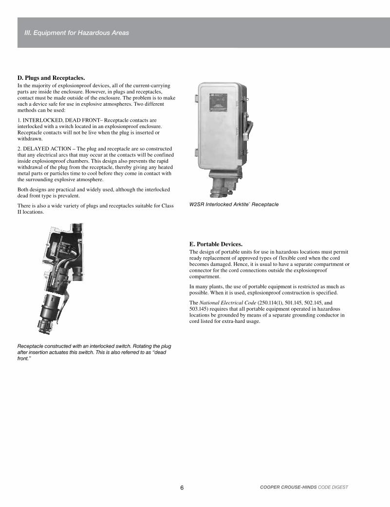
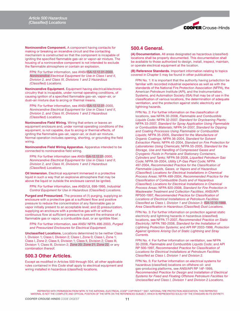
D. Plugs and Receptacles.In the majority of explosionproof devices, all of the current-carrying parts are inside the enclosure. However, in plugs and receptacles, contact must be made outside of the enclosure. The problem is to make such a device safe for use in explosive atmospheres. Two different methods can be used:
1. INTERLOCKED, DEAD FRONT– Receptacle contacts are interlocked with a switch located in an explosionproof enclosure. Receptacle contacts will not be live when the plug is inserted or withdrawn.
2. DELAYED ACTION – The plug and receptacle are so constructed that any electrical arcs that may occur at the contacts will be confined inside explosionproof chambers. This design also prevents the rapid withdrawal of the plug from the receptacle, thereby giving any heated metal parts or particles time to cool before they come in contact with the surrounding explosive atmosphere.
Both designs are practical and widely used, although the interlocked dead front type is prevalent.
There is also a wide variety of plugs and receptacles suitable for Class II locations.
Receptacle constructed with an interlocked switch. Rotating the plug after insertion actuates this switch. This is also referred to as “dead front.”
W2SR Interlocked Arktite® Receptacle
E. Portable Devices.The design of portable units for use in hazardous locations must permit ready replacement of approved types of flexible cord when the cord becomes damaged. Hence, it is usual to have a separate compartment or connector for the cord connections outside the explosionproof compartment.
In many plants, the use of portable equipment is restricted as much as possible. When it is used, explosionproof construction is specified.
The National Electrical Code (250.114(1), 501.145, 502.145, and 503.145) requires that all portable equipment operated in hazardous locations be grounded by means of a separate grounding conductor in cord listed for extra-hard usage.
III. Equipment for Hazardous Areas

7COOPER CROUSE-HINDS CODE DIGEST
A. Conduit.In Class I, Division 1, locations, all conduit must be rigid metal or steel IMC with at least five full tapered threads tightly engaged in the enclosure. (An exception to 500.8(E) allows 4-1/2 for factory threaded NPT entries.) All factory-drilled and tapped Crouse-Hinds enclosures satisfy this requirement. When field drilling and tapping is performed it may be required to drill and tap deeper than standard NPT to insure engagement of five full threads. For further information contact your Crouse-Hinds field representative.
A common method of wiring employs thick-walled conduit with a corrosion-resistant finish. In addition to the protective finish on the conduit, various types of paints or special finishes are used extensively to give extra protection from corrosive atmospheres.
Alternate changes in temperature and barometric pressure cause “breathing” — the entry and circulation of air throughout the conduit. As joints in a conduit system and its components are seldom tight enough to prevent this breathing, moisture in the air condenses and collects at the base of vertical conduit runs and equipment enclosures. This could cause equipment shorts or grounds. To eliminate this condition, inspection fittings should be installed and equipped with explosionproof drains to automatically drain off the water.
EZD Drain Seal
B. Seals for Conduit System.NEC 501.15 requires that sealing fittings filled with approved compound be installed in conduits entering explosionproof enclosures. Seals are necessary to limit volume, to prevent an explosion from traveling throughout the conduit system, to block gases or vapors from moving from a hazardous to a nonhazardous area through connecting raceways or from enclosure to enclosure, and to stop pressure piling — the buildup of pressure inside conduit lines caused by precompression as the explosion travels through the conduit. (See Appendix III — Selection of Seals and Drains.)
The standard type seals are not intended to prevent the passage of liquids, gases or vapors at pressures continuously above atmospheric. Temperature extremes and highly corrosive liquids and vapors may affect the ability of seals to perform their intended function.
In hazardous locations, seals are needed in the following instances:
temperature equipment. (A seal must be within 18 inches or closer if the manufacturer’s instructions so specify of the enclosure it isolates.)
taps, if the conduit is 2-inch trade size or larger.
2 hazardous area to a nonhazardous location.
NEC 501.15(A)(1) permits explosionproof unions, couplings, reducers, elbows, and OE’s to be placed between the seal and the explosionproof enclosure.
EYSX Series – For sealing in vertical or horizontal conduit runs. Class I, Groups A, B, C, D, and Class ll, Groups E, F, and G.
EZS Series – For conduits running at any angle between vertical and horizontal. Class I, Groups C, D, and Class II, Groups E, F, and G.
Typical sealing in Class I, Division 1 location
EPL PowerPlus
EYS Seal
EYS Seal
EZS Seal
EZS Seal
GUAC Seal
Service
EFSSwitch
Seal
Factory Seal
EVMLtg.fix.
EBMC
Hazardous
IV. Wiring Methods and Materials

8 COOPER CROUSE-HINDS CODE DIGEST
C. Mineral-lnsulated Cable.Another type of wiring system suitable for Division 1 is mineral-insulated (MI) cable. Mineral-insulated wiring consists of copper conductors properly spaced and encased in tightly compressed magnesium oxide, clad in an overall copper sheath.
Below the melting temperature of the copper sheath, MI cable is impervious to fire. Because of limitations on end connections, its operating range is generally considered to be -40 to 80°C with standard terminals, and up to 250°C with special terminals.
When properly installed, MI cable is suitable for all Class I and Class II locations.
MI cable is available with one to 17 conductors, making it most suitable for wiring of control boards, control components and instrumentation circuits where crowded conditions make conduit installations difficult and expensive.
MI cable is hygroscopic; therefore, moisture can be a problem when the ends are left exposed. Care must be taken to install and seal the end fittings as soon as possible to prevent moisture accumulation. If moisture enters, the end must be cut off or dried out with a torch.
D. Metal-Clad Cable.Metal-clad cable (Type MC) is permitted by the National Electrical Code for application in Class I, Division 2 locations.
Use of this type of cable is not limited to any voltage class. The armor itself is available in various metals. When further protection from chemical attack is needed, a supplemental protective jacket may be used.
The NEC also permits, under certain restrictions, a particular kind of metal-clad cable (MC-HL) to be used in Class I, Division 1 locations. This is detailed in 501.10(A)(1)(c). Similarly, 501.10(A)(1)(d) permits a certain type of Instrumentation Tray Cable (ITC-HL).
TMC Terminator™ cable fittings for use with Type MC jacketed metal-clad cables with interlocked or corrugated armor in unclassified locations and certain Class I, Division 2 applications.
TMCX Terminator cable fittings are suitable for use with Type MC jacketed metal-clad cables with interlocked or corrugated armor and Type TC tray cable in Class I, Division 2, Groups A, B, C, and D locations. TMCX fittings are suitable for use with Type MC-HL and Type ITC-HL cable listed for use in Class I, Division 1.
E. Tray Cable.Power and control tray cable (Type TC) is permitted in Class I, Division 2 locations. It is a factory assembly of two or more insulated conductors with or without the grounding conductor under a nonmetallic sheath.
F. Other Permitted Cables.In Class I, Division 2 locations, the NEC also recognizes the use of Type PLTC, similar to TC except the conductors are limited to No. 22 through No. 16; also Type MV, a single or multiconductor solid dielectric insulated cable rated 2001 volts or higher. The NEC also permits Type ITC cable, as covered by Article 727, Instrumentation Tray Cable, which details its construction and use.
G. Cable Sealing.In Class I, Division 1 locations the use of cable, except types MI, MC-HL and ITC-HL, is limited to installation in conduit. Multiconductor cables that cannot transmit gases through the cores are sealed as single conductors; this type of cable, however, is not readily available. If a cable can transmit gases through its core, the outer jacket must be removed so that the sealing compound surrounds each individual insulated conductor and the jacket, or it can be sealed as a single conductor if the cable end in the enclosure is sealed by an approved means. Crouse-Hinds TSC epoxy is such a means.
In Class I, Division 2 locations cables must be sealed where they enter enclosures required to be explosionproof. As mentioned previously, TMCX fittings are recommended where Types MC, ITC, or TC cables are used.
In the case of extra-hard-usage flexible cord, EYS seals with appropriate cable terminators are recommended. If the cable core can transmit gases, the outer jacket must be removed so that the sealing compound surrounds each conductor to prevent the passage of gases. Cables without a gas-tight continuous sheath must be sealed at the boundary of the Division 2 and unclassified locations.
If attached to equipment that may cause a pressure at a cable end, a sheathed cable that can transmit gases through its core must be sealed to prevent migration of gases into an unclassified area.
H. Nonmetallic Conduit.Under certain restrictions, in Class I, Division 2 locations, reinforced thermosetting resin conduit (RTRC) and Schedule 80 PVC conduit and associated fittings may be used.
IV. Wiring Methods and Materials

9COOPER CROUSE-HINDS CODE DIGEST
Chapter 5 of the NEC requires equipment to be constructed and installed in such a way as to insure safe performance under conditions of proper use and maintenance.
It is important that the following points be checked carefully:
A. Electrical Circuits.Electrical equipment should be serviced or disassembled only after first de-energizing the electrical supply circuits. This also applies when luminaires or units are partially disassembled for relamping. All electrical enclosures should be tightly reassembled before the supply circuits are re-energized.
B. Assembly or Disassembly of Enclosures.Hammers or prying tools must not be allowed to damage the flat-joint surfaces. Do not handle covers roughly, or place them on surfaces that might damage or scratch the flat-joint surfaces. Protect all surfaces that form a part of the flame path from damage. In storing equipment, always make sure that covers are assembled to their mating bodies.
C. Cover Attachment Screws.All cover screws and bolts intended to hold explosionproof joints firmly together must always be tight while circuits are live. Leaving screws or bolts loose may make the equipment unsafe. Care should be taken to use only bolts or screws provided by the equipment manufacturer, as the substitution of other types of material may weaken the assembly and make it unsafe.
D. Cleaning and Lubrication.Particles of foreign material should not be allowed to accumulate on flat or threaded joints as these materials tend to prevent a close fit and may permit dangerous arcs, sparks or flames to propagate through them.
When assembling, remove all old grease, dirt, paint or other foreign material from the surfaces, using a brush and kerosene or a similar solvent with a flash point higher than 38°C (100°F). A film of light oil or lubricant of a type recommended by the equipment manufacturer should be applied to both body and cover joint.
Any lubricated joints exposed for long periods of time may attract small particles of dirt or other foreign material. To avoid this, body and cover joints should be reassembled immediately.
Threaded joints should be tightened sufficiently to prevent accidental loosening due to vibration, but they should not be forced. If the threads are kept clean and lubricated, safe operation can be assured with a minimum of maintenance.
E. Shaft and Bearing Surfaces.Because a rotating shaft must turn freely, the clearance between shaft and bearing is carefully established within close tolerances by the equipment manufacturer. This clearance should be maintained to prevent flames or sparks from escaping to the external hazardous atmosphere. Always follow the manufacturer’s recommendations with respect to lubrication and other servicing.
F. Corrosive Locations.Threaded covers, flat joints, surfaces, rotating shafts, bearings and operating shafts should be well lubricated. If corrosion products have accumulated on explosionproof joints or surfaces and cannot readily be removed with solvents, the parts should be discarded and replaced. Never use an abrasive material or a file to remove the corrosion products from threaded or flat-joint surfaces. In extremely corrosive locations, equipment should be periodically inspected to guard against unusual deterioration and possible porosity, since this may weaken the enclosure structurally.
G. Portable Equipment.The extra-hard-usage flexible cord that must be used with this equipment should be examined frequently and replaced at the first indication of mechanical damage or deterioration. Terminal connections to the cord must be properly maintained. In general, where portable equipment is necessary, avoid rough handling and inspect the assembly frequently.
H. Overall Safety.Safety in hazardous locations may be compromised if additional openings or other alterations are made in assemblies specifically designed for use in these locations.
In painting the exterior of housings for hazardous locations, care should be taken not to obscure the nameplate, which may contain cautionary or other information of importance to maintenance personnel.
I. Plug-in Replacement Units.One technique that speeds and eases the work of the maintenance department is the use of plug-in type electrical equipment that allows the substitution of a replacement unit while the original unit is being repaired outside the hazardous area.
J. Maintenance.Cooper Crouse-Hinds recommends an Electrical Preventive Maintenance Program as described in the National Fire Protection Association Bulletin NFPA 70B, Recommended Practice for Electrical Equipment Maintenance (www.nfpa.org).
Code Digest Preface:The following pages contain, in red print and a type font known as Helvetica, Articles 500 through 516 from the 2008 National Electrical Code. Diagrams that are part of the NEC have a red border around them.
Changes in the 2008 edition of the National Electrical Code are indicated by gray shading.
Bullets in the margin identify the location where material in the 2008 National Electrical Code was deleted.
Cooper Crouse-Hinds explanatory text and diagrams are in black and Times New Roman font to differentiate them from NEC material Photographs and Appendices are not part of the NEC.
V. Maintenance Principles

REPRINTED WITH PERMISSION FROM NFPA 70 THE NATIONAL ELECTRICAL CODE® COPYRIGHT © 2007, NATIONAL FIRE PROTECTION ASSOCIATION. THIS REPRINTED
MATERIAL IS NOT THE COMPLETE AND OFFICIAL POSITION OF THE NFPA ON THE REFERENCED SUBJECT, WHICH IS REPRESENTED SOLELY BY THE STANDARD IN ITS ENTIRETY.
10 COOPER CROUSE-HINDS CODE DIGEST
Article 500FPN: Rules that are followed by a reference in brackets contain text that has been extracted from NFPA 497-2004, Recommended Practice for the Classification of Flammable Liquids, Gases, or Vapors and of Hazardous (Classified) Locations for Electrical Installations in Chemical Process Areas, and NFPA 499-2004, Recommended Practice for the Classification of Combustible Dusts and of Hazardous (Classified) Locations for Electrical Installation in Chemical Process Areas. Only editorial changes were made to the extracted text to make it consistent with this Code.
500.1 Scope – Articles 500 Through 504.Articles 500 through 504 cover the requirements for electrical and electronic equipment and wiring for all voltages in Class I, Divisions 1 and 2; Class II, Divisions 1 and 2; and Class III, Divisions 1 and 2 locations where fire or explosion hazards may exist due to flammable gases, flammable liquid–produced vapors, combustible liquid–produced vapors, combustible dusts, or ignitible fibers/flyings.
FPN No. 1: The unique hazards associated with explosives, pyrotechnics, and blasting agents are not addressed in this article.
FPN No. 2: For the requirements for electrical and electronic equipment and wiring for all voltages in Class I, Zone 0, Zone 1, and Zone 2 hazardous (classified) locations where fire or explosion hazards may exist due to flammable gases or vapors or flammable liquids, refer to Article 505.
FPN No. 3: For the requirements for electrical and electronic equipment and wiring for all voltages in Zone 20, Zone 21, and Zone 22 hazardous (classified) locations where fire or explosion hazards may exist due to combustible dusts or ignitible fibers/flyings, refer to Article 506.
500.2 Definitions.For purposes of Articles 500 through 504 and Articles 510 through 516, the following definitions apply.
Associated Nonincendive Field Wiring Apparatus. Apparatus in which the circuits are not necessarily nonincendive themselves but that affect the energy in nonincendive field wiring circuits and are relied upon to maintain nonincendive energy levels. Associated nonincendive field wiring apparatus may be either of the following:
(1) Electrical apparatus that has an alternative type of protection for use in the appropriate hazardous (classified) location
(2) Electrical apparatus not so protected that shall not be used in a hazardous (classified) location
FPN: Associated nonincendive field wiring apparatus has designated associated nonincendive field wiring apparatus connections for nonincendive field wiring apparatus and may also have connections for other electrical apparatus.
Combustible Gas Detection System. A protection technique utilizing stationary gas detectors in industrial establishments.
Control Drawing. A drawing or other document provided by the manufacturer of the intrinsically safe or associated apparatus, or of the nonincendive field wiring apparatus or associated nonincendive field wiring apparatus, that details the allowed interconnections
between the intrinsically safe and associated apparatus or between the nonincendive field wiring apparatus or associated nonincendive field wiring apparatus.
Dust-Ignitionproof. Equipment enclosed in a manner that excludes dusts and does not permit arcs, sparks, or heat otherwise generated or liberated inside of the enclosure to cause ignition of exterior accumulations or atmospheric suspensions of a specified dust on or in the vicinity of the enclosure.
FPN: For further information on dust-ignitionproof enclosures, see Type 9 enclosure in ANSI/NEMA 250-1991, Enclosures for Electrical Equipment, and ANSI/UL 1203-1994, Explosionproof and Dust-Ignitionproof Electrical Equipment for Hazardous (Classified) Locations.
Dusttight. Enclosures constructed so that dust will not enter under specified test conditions.
FPN: See ANSI/ISA-12.12.01-2000, Nonincendive Electrical Equipment for Use in Class I and II, Division 2, and Class III, Divisions 1 and 2 Hazardous (Classified) Locations.
Electrical and Electronic Equipment. Materials, fittings, devices, appliances, and the like that are part of, or in connection with, an electrical installation.
FPN: Portable or transportable equipment having self-contained power supplies, such as battery-operated equipment, could potentially become an ignition source in hazardous (classified) locations. See ISA-RP12.12.03-2002, Portable Electronic Products Suitable for Use in Class I and II, Division 2, Class I Zone 2 and Class III, Division 1 and 2 Hazardous (Classified) Locations.
Explosionproof Apparatus. Apparatus enclosed in a case that is capable of withstanding an explosion of a specified gas or vapor that may occur within it and of preventing the ignition of a specified gas or vapor surrounding the enclosure by sparks, flashes, or explosion of the gas or vapor within, and that operates at such an external temperature that a surrounding flammable atmosphere will not be ignited thereby.
FPN: For further information, see ANSI/UL 1203-1994, Explosion-Proof and Dust-Ignition-Proof Electrical Equipment for Use in Hazardous (Classified) Locations.
Hermetically Sealed. Equipment sealed against the entrance of an external atmosphere where the seal is made by fusion, for example, soldering, brazing, welding, or the fusion of glass to metal.
FPN: For further information, see ANSI/ISA-12.12.01-2000, Nonincendive Electrical Equipment for Use in Class I and II, Division 2, and Class III, Division 1 and 2 Hazardous (Classified) Locations.
Nonincendive Circuit. A circuit, other than field wiring, in which any arc or thermal effect produced under intended operating conditions of the equipment is not capable, under specified test conditions, of igniting the flammable gas–air, vapor–air, or dust–air mixture.
FPN: Conditions are described in ANSI/ISA-12.12.01-2000, Nonincendive Electrical Equipment for Use in Class I and II, Division 2, and Class III, Divisions 1 and 2 Hazardous (Classified) Locations.
Article 500 – Hazardous (Classified) Locations, Classes I, II, and III, Divisions 1 and 2
VI. Selected Articles from the National Electrical Code – 2008
REPRINTED WITH PERMISSION FROM NFPA 70 THE NATIONAL ELECTRICAL CODE® COPYRIGHT © 2007, NATIONAL FIRE PROTECTION ASSOCIATION. THIS REPRINTED
MATERIAL IS NOT THE COMPLETE AND OFFICIAL POSITION OF THE NFPA ON THE REFERENCED SUBJECT, WHICH IS REPRESENTED SOLELY BY THE STANDARD IN ITS ENTIRETY.
11COOPER CROUSE-HINDS CODE DIGEST
Nonincendive Component. A component having contacts for making or breaking an incendive circuit and the contacting mechanism is constructed so that the component is incapable of igniting the specified flammable gas–air or vapor–air mixture. The housing of a nonincendive component is not intended to exclude the flammable atmosphere or contain an explosion.
FPN: For further information, see ANSI/ISA-12.12.01-2000, Nonincendive Electrical Equipment for Use in Class I and II, Division 2, and Class III, Divisions 1 and 2 Hazardous (Classified) Locations.
Nonincendive Equipment. Equipment having electrical/electronic circuitry that is incapable, under normal operating conditions, of causing ignition of a specified flammable gas–air, vapor–air, or dust–air mixture due to arcing or thermal means.
FPN: For further information, see ANSI/ISA-12.12.01-2000, Nonincendive Electrical Equipment for Use in Class I and II, Division 2, and Class III, Divisions 1 and 2 Hazardous (Classified) Locations.
Nonincendive Field Wiring. Wiring that enters or leaves an equipment enclosure and, under normal operating conditions of the equipment, is not capable, due to arcing or thermal effects, of igniting the flammable gas–air, vapor–air, or dust–air mixture. Normal operation includes opening, shorting, or grounding the field wiring.
Nonincendive Field Wiring Apparatus. Apparatus intended to be connected to nonincendive field wiring.
FPN: For further information see ANSI/ISA-12.12.01-2000, Nonincendive Electrical Equipment for Use in Class I and II, Division 2, and Class III, Divisions 1 and 2 Hazardous (Classified) Locations.
Oil Immersion. Electrical equipment immersed in a protective liquid in such a way that an explosive atmosphere that may be above the liquid or outside the enclosure cannot be ignited.
FPN: For further information, see ANSI/UL 698-1995, Industrial Control Equipment for Use in Hazardous (Classified) Locations.
Purged and Pressurized. The process of (1) purging, supplying an enclosure with a protective gas at a sufficient flow and positive pressure to reduce the concentration of any flammable gas or vapor initially present to an acceptable level; and (2) pressurization, supplying an enclosure with a protective gas with or without continuous flow at sufficient pressure to prevent the entrance of a flammable gas or vapor, a combustible dust, or an ignitible fiber.
FPN: For further information, see ANSI/ NFPA 496-2003, Purged and Pressurized Enclosures for Electrical Equipment.
Unclassified Locations. Locations determined to be neither Class I, Division 1; Class I, Division 2; Class I, Zone 0; Class I, Zone 1; Class I, Zone 2; Class II, Division 1; Class II, Division 2; Class III, Division 1; Class III, Division 2; Zone 20; Zone 21; Zone 22; or any combination thereof.
500.3 Other Articles.Except as modified in Articles 500 through 504, all other applicable rules contained in this Code shall apply to electrical equipment and wiring installed in hazardous (classified) locations.
500.4 General.(A) Documentation. All areas designated as hazardous (classified) locations shall be properly documented. This documentation shall be available to those authorized to design, install, inspect, maintain, or operate electrical equipment at the location.
(B) Reference Standards. Important information relating to topics covered in Chapter 5 may be found in other publications.
FPN No. 1: It is important that the authority having jurisdiction be familiar with recorded industrial experience as well as with the standards of the National Fire Protection Association (NFPA), the American Petroleum Institute (API), and the Instrumentation, Systems, and Automation Society (ISA) that may be of use in the classification of various locations, the determination of adequate ventilation, and the protection against static electricity and lightning hazards.
FPN No. 2: For further information on the classification of locations, see NFPA 30-2008, Flammable and Combustible Liquids Code; NFPA 32-2007, Standard for Drycleaning Plants; NFPA 33-2007, Standard for Spray Application Using Flammable or Combustible Materials; NFPA 34-2007, Standard for Dipping and Coating Processes Using Flammable or Combustible Liquids; NFPA 35-2005, Standard for the Manufacture of Organic Coatings; NFPA 36-2004, Standard for Solvent Extraction Plants; NFPA 45-2004, Standard on Fire Protection for Laboratories Using Chemicals; NFPA 55-2005, Standard for the Storage, Use and Handling of Compressed Gases and Cryogenic Fluids in Portable and Stationary Containers, Cylinders and Tanks; NFPA 58-2008, Liquefied Petroleum Gas Code; NFPA 59-2004, Utility LP-Gas Plant Code; NFPA 497-2004, Recommended Practice for the Classification of Flammable Liquids, Gases, or Vapors and of Hazardous (Classified) Locations for Electrical Installations in Chemical Process Areas; NFPA 499-2004, Recommended Practice for the Classification of Combustible Dusts and of Hazardous (Classified) Locations for Electrical Installations in Chemical Process Areas; NFPA 820-2008, Standard for Fire Protection in Wastewater Treatment and Collection Facilities; ANSI/API RP500-1997, Recommended Practice for Classification of Locations of Electrical Installations at Petroleum Facilities Classified as Class I, Division 1 and Division 2; ISA-12.10-1988, Area Classification in Hazardous (Classified) Dust Locations.
FPN No. 3: For further information on protection against static electricity and lightning hazards in hazardous (classified) locations, see NFPA 77-2007, Recommended Practice on Static Electricity; NFPA 780-2008, Standard for the Installation of Lightning Protection Systems; and API RP 2003-1998, Protection Against Ignitions Arising Out of Static Lightning and Stray Currents.
FPN No. 4: For further information on ventilation, see NFPA 30-2008, Flammable and Combustible Liquids Code; and API RP 500-1997, Recommended Practice for Classification of Locations for Electrical Installations at Petroleum Facilities Classified as Class I, Division 1 and Division 2.
FPN No. 5: For further information on electrical systems for hazardous (classified) locations on offshore oil- and gas-producing platforms, see ANSI/API RP 14F-1999, Recommended Practice for Design and Installation of Electrical Systems for Fixed and Floating Offshore Petroleum Facilities for Unclassified and Class I, Division 1 and Division 2 Locations.
Article 500 Hazardous(Classified) Locations

REPRINTED WITH PERMISSION FROM NFPA 70 THE NATIONAL ELECTRICAL CODE® COPYRIGHT © 2007, NATIONAL FIRE PROTECTION ASSOCIATION. THIS REPRINTED
MATERIAL IS NOT THE COMPLETE AND OFFICIAL POSITION OF THE NFPA ON THE REFERENCED SUBJECT, WHICH IS REPRESENTED SOLELY BY THE STANDARD IN ITS ENTIRETY.
12 COOPER CROUSE-HINDS CODE DIGEST
500.5 Classifications of Locations.(A) Classifications of Locations. Locations shall be classified depending on the properties of the flammable gas, flammable liquid-produced vapor, combustible-liquid produced vapors, combustible dusts, or fibers/flyings that may be present, and the likelihood that a flammable or combustible concentration or quantity is present. Where pyrophoric materials are the only materials used or handled, these locations shall not be classified. Each room, section, or area shall be considered individually in determining its classification.
FPN: Through the exercise of ingenuity in the layout of electrical installations for hazardous (classified) locations, it is frequently possible to locate much of the equipment in a reduced level of classification or in an unclassified location and, thus, to reduce the amount of special equipment required.
Rooms and areas containing ammonia refrigeration systems that are equipped with adequate mechanical ventilation may be classified as “unclassified” locations.
FPN: For further information regarding classification and ventilation of areas involving ammonia, see ANSI/ASHRAE 15-1994, Safety Code for Mechanical Refrigeration, and ANSI/CGA G2.1-1989, Safety Requirements for the Storage and Handling of Anhydrous Ammonia.
(B) Class I Locations. Class I locations are those in which flammable gases, flammable liquid–produced vapors, or combustible liquid–produced vapors are or may be present in the air in quantities sufficient to produce explosive or ignitible mixtures. Class I locations shall include those specified in 500.5(B)(1) and (B)(2).
(1) Class I, Division 1. A Class I, Division 1 location is a location
(1) In which ignitible concentrations of flammable gases, flammable liquid–produced vapors, or combustible liquid–produced vapors can exist under normal operating conditions, or
(2) In which ignitible concentrations of such flammable gases, flammable liquid–produced vapors, or combustible liquids above their flash points may exist frequently because of repair or maintenance operations or because of leakage, or
(3) In which breakdown or faulty operation of equipment or processes might release ignitible concentrations of flammable gases, flammable liquid–produced vapors, or combustible liquid–produced vapors and might also cause simultaneous failure of electrical equipment in such a way as to directly cause the electrical equipment to become a source of ignition.
FPN No. 1: This classification usually includes the following locations:
(1) Where volatile flammable liquids or liquefied flammable gases are transferred from one container to another
(2) Interiors of spray booths and areas in the vicinity of spraying and painting operations where volatile flammable solvents are used
(3) Locations containing open tanks or vats of volatile flammable liquids
(4) Drying rooms or compartments for the evaporation of flammable solvents
(5) Locations containing fat- and oil-extraction equipment using volatile flammable solvents
(6) Portions of cleaning and dyeing plants where flammable liquids are used
(7) Gas generator rooms and other portions of gas manufacturing plants where flammable gas may escape
(8) Inadequately ventilated pump rooms for flammable gas or for volatile flammable liquids
(9) The interiors of refrigerators and freezers in which volatile flammable materials are stored in open, lightly stoppered, or easily ruptured containers
(10) All other locations where ignitible concentrations of flam-mable vapors or gases are likely to occur in the course of normal operations
FPN No. 2: In some Division 1 locations, ignitible concentrations of flammable gases or vapors may be present continuously or for long periods of time. Examples include the following:
(1) The inside of inadequately vented enclosures containing instruments normally venting flammable gases or vapors to the interior of the enclosure
(2) The inside of vented tanks containing volatile flammable liquids
(3) The area between the inner and outer roof sections of a floating roof tank containing volatile flammable fluids
(4) Inadequately ventilated areas within spraying or coating operations using volatile flammable fluids
(5) The interior of an exhaust duct that is used to vent ignitible concentrations of gases or vapors
Experience has demonstrated the prudence of avoiding the installation of instrumentation or other electric equipment in these particular areas altogether or where it cannot be avoided because it is essential to the process and other locations are not feasible [see 500.5(A), FPN] using electric equipment or instrumentation approved for the specific application or consisting of intrinsically safe systems as described in Article 504.
(2) Class I, Division 2. A Class I, Division 2 location is a location
(1) In which volatile flammable gases, flammable liquid–produced vapors, or combustible liquid–produced vapors are handled, processed, or used, but in which the liquids, vapors, or gases will normally be confined within closed containers or closed systems from which they can escape only in case of accidental rupture or breakdown of such containers or systems or in case of abnormal operation of equipment, or
(2) In which ignitible concentrations of flammable gases, flammable liquid–produced vapors, or combustible liquid–produced vapors are normally prevented by positive mechanical ventilation and which might become hazardous through failure or abnormal operation of the ventilating equipment, or
(3) That is adjacent to a Class I, Division 1 location, and to which ignitible concentrations of flammable gases, flammable liquid–produced vapors, or combustible liquid–produced vapors above their flash points might occasionally be communicated unless such communication is prevented by adequate positive-pressure ventilation from a source of clean air and effective safeguards against ventilation failure are provided.
FPN No. 1: This classification usually includes locations where volatile flammable liquids or flammable gases or vapors are used but that, in the judgment of the authority having jurisdiction, would become hazardous only in case of an accident or of some unusual operating condition. The quantity of
Article 500 Hazardous(Classified) Locations
REPRINTED WITH PERMISSION FROM NFPA 70 THE NATIONAL ELECTRICAL CODE® COPYRIGHT © 2007, NATIONAL FIRE PROTECTION ASSOCIATION. THIS REPRINTED
MATERIAL IS NOT THE COMPLETE AND OFFICIAL POSITION OF THE NFPA ON THE REFERENCED SUBJECT, WHICH IS REPRESENTED SOLELY BY THE STANDARD IN ITS ENTIRETY.
13COOPER CROUSE-HINDS CODE DIGEST
flammable material that might escape in case of accident, the adequacy of ventilating equipment, the total area involved, and the record of the industry or business with respect to explosions or fires are all factors that merit consideration in determining the classification and extent of each location.
FPN No. 2: Piping without valves, checks, meters, and similar devices would not ordinarily introduce a hazardous condition even though used for flammable liquids or gases. Depending on factors such as the quantity and size of the containers and ventilation, locations used for the storage of flammable liquids or liquefied or compressed gases in sealed containers may be considered either hazardous (classified) or unclassified locations. See NFPA 30-2008, Flammable and Combustible Liquids Code, and NFPA 58-2008, Liquefied Petroleum Gas Code.
(C) Class II Locations. Class II locations are those that are hazardous because of the presence of combustible dust. Class II locations shall include those specified in 500.5(C)(1) and (C)(2).
(1) Class II, Division 1. A Class II, Division 1 location is a location
(1) In which combustible dust is in the air under normal operating conditions in quantities sufficient to produce explosive or ignitible mixtures, or
(2) Where mechanical failure or abnormal operation of machinery or equipment might cause such explosive or ignitible mixtures to be produced, and might also provide a source of ignition through simultaneous failure of electric equipment, through operation of protection devices, or from other causes, or
(3) In which Group E combustible dusts may be present in quantities sufficient to be hazardous.
FPN: Dusts containing magnesium or aluminum are particularly hazardous, and the use of extreme precaution is necessary to avoid ignition and explosion.
(2) Class II, Division 2. A Class II, Division 2 location is a location
(1) In which combustible dust due to abnormal operations may be present in the air in quantities sufficient to produce explosive or ignitible mixtures; or
(2) Where combustible dust accumulations are present but are normally insufficient to interfere with the normal operation of electrical equipment or other apparatus, but could as a result of infrequent malfunctioning of handling or processing equipment become suspended in the air; or
(3) In which combustible dust accumulations on, in, or in the vicinity of the electrical equipment could be sufficient to interfere with the safe dissipation of heat from electrical equipment, or could be ignitible by abnormal operation or failure of electrical equipment.
FPN No. 1: The quantity of combustible dust that may be present and the adequacy of dust removal systems are factors that merit consideration in determining the classification and may result in an unclassified area.
FPN No. 2: Where products such as seed are handled in a manner that produces low quantities of dust, the amount of dust deposited may not warrant classification.
(D) Class III Locations. Class III locations are those that are hazardous because of the presence of easily ignitible fibers or materials producing combustible flyings are handled, manufactured, or used, but in which such fibers/flyings are not
likely to be in suspension in the air in quantities sufficient to produce ignitible mixtures. Class III locations shall include those specified in 500.5(D)(1) and (D)(2).
(1) Class III, Division 1. A Class III, Division 1 location is a location in which easily ignitible fibers/flyings are handled, manufactured, or used.
FPN No. 1: Such locations usually include some parts of rayon, cotton, and other textile mills; combustible fiber/flyings manufacturing and processing plants; cotton gins and cotton-seed mills; flax-processing plants; clothing manufacturing plants; woodworking plants; and establishments and industries involving similar hazardous processes or conditions.
FPN No. 2: Easily ignitible fibers/flyings include rayon, cotton (including cotton linters and cotton waste), sisal or henequen, istle, jute, hemp, tow, cocoa fiber, oakum, baled waste kapok, Spanish moss, excelsior, and other materials of similar nature.
(2) Class III, Division 2. A Class III, Division 2 location is a location in which easily ignitible fibers/flyings are stored or handled other than in the process of manufacture.
500.6 Material Groups.For purposes of testing, approval, and area classification, various air mixtures (not oxygen-enriched) shall be grouped in accordance with 500.6(A) and 500.6(B).
Exception: Equipment identified for a specific gas, vapor, or dust.
FPN: This grouping is based on the characteristics of the materials. Facilities are available for testing and identifying equipment for use in the various atmospheric groups.
(A) Class I Group Classifications. Class I groups shall be according to 500.6(A)(1) through (A)(4).
FPN No. 1: FPN Nos. 2 and 3 apply to 500.6(A).
FPN No. 2: The explosion characteristics of air mixtures of gases or vapors vary with the specific material involved. For Class I locations, Groups A, B, C, and D, the classification involves determinations of maximum explosion pressure and maximum safe clearance between parts of a clamped joint in an enclosure. It is necessary, therefore, that equipment be identified not only for class but also for the specific group of the gas or vapor that will be present.
FPN No. 3: Certain chemical atmospheres may have characteristics that require safeguards beyond those required for any of the Class I groups. Carbon disulfide is one of these chemicals because of its low ignition temperature (90°C) and the small joint clearance permitted to arrest its flame.
(1) Group A. Acetylene. [497:3.3.5.1.1]
(2) Group B. Flammable gas, flammable liquid–produced vapor, or combustible liquid–produced vapor mixed with air that may burn or explode, having either a maximum experimental safe gap (MESG) value less than or equal to 0.45 mm or a minimum igniting current
ratio (MIC ratio) less than or equal to 0.40. [497:3.3.5.1.2]
FPN: A typical Class I, Group B material is hydrogen.
Exception No. 1: Group D equipment shall be permitted to be used for atmospheres containing butadiene, provided all conduit runs into explosionproof equipment are provided with explosionproof seals installed within 450 mm (18 in.) of the enclosure.
Article 500 Hazardous(Classified) Locations

REPRINTED WITH PERMISSION FROM NFPA 70 THE NATIONAL ELECTRICAL CODE® COPYRIGHT © 2007, NATIONAL FIRE PROTECTION ASSOCIATION. THIS REPRINTED
MATERIAL IS NOT THE COMPLETE AND OFFICIAL POSITION OF THE NFPA ON THE REFERENCED SUBJECT, WHICH IS REPRESENTED SOLELY BY THE STANDARD IN ITS ENTIRETY.
14 COOPER CROUSE-HINDS CODE DIGEST
Exception No. 2: Group C equipment shall be permitted to be used for atmospheres containing allyl glycidyl ether, n-butyl glycidyl ether, ethylene oxide, propylene oxide, and acrolein, provided all conduit runs into explosionproof equipment are provided with explosionproof seals installed within 450 mm (18 in.) of the enclosure.
(3) Group C. Flammable gas, flammable liquid–produced vapor, or combustible liquid–produced vapor mixed with air that may burn or explode, having either a maximum experimental safe gap (MESG) value greater than 0.45 mm and less than or equal to 0.75 mm, or a minimum igniting current ratio (MIC ratio) greater than 0.40 and less
than or equal to 0.80. [497:3.3.5.1.3]
FPN: A typical Class I, Group C material is ethylene.
(4) Group D. Flammable gas, flammable liquid–produced vapor, or combustible liquid–produced vapor mixed with air that may burn or explode, having either a maximum experimental safe gap (MESG) value greater than 0.75 mm or a minimum igniting current ratio (MIC
ratio) greater than 0.80. [497:3.3.5.1.4]
FPN No. 1: A typical Class I, Group D material is propane.
FPN No. 2: For classification of areas involving ammonia atmospheres, see ANSI/ASHRAE 15-1994, Safety Code for Mechanical Refrigeration, and ANSI/CGA G2.1-1989, Safety Requirements for the Storage and Handling of Anhydrous Ammonia.
(B) Class II Group Classifications. Class II groups shall be in accordance with 500.6(B)(1) through (B)(3).
(1) Group E. Atmospheres containing combustible metal dusts, including aluminum, magnesium, and their commercial alloys, or other combustible dusts whose particle size, abrasiveness, and conductivity present similar hazards in the use of electrical
equipment. [499:3.3.4.1]
FPN: Certain metal dusts may have characteristics that require safeguards beyond those required for atmospheres containing the dusts of aluminum, magnesium, and their commercial alloys. For example, zirconium, thorium, and uranium dusts have extremely low ignition temperatures [as low as 20°C (68°F)] and minimum ignition energies lower than any material classified in any of the Class I or Class II groups.
(2) Group F. Atmospheres containing combustible carbonaceous dusts that have more than 8 percent total entrapped volatiles (see ASTM D 3175-02, Standard Test Method for Volatile Material in the Analysis Sample for Coal and Coke, for coal and coke dusts) or that have been sensitized by other materials so that they present an explosion hazard. Coal, carbon black, charcoal, and coke dusts are
examples of carbonaceous dusts. [499:3.3.4.2]
(3) Group G. Atmospheres containing combustible dusts not included in Group E or F, including flour, grain, wood, plastic, and chemicals.
FPN No. 1: For additional information on group classification of Class II materials, see NFPA 499-2004, Recommended Practice for the Classification of Combustible Dusts and of Hazardous (Classified) Locations for Electrical Installations in Chemical Process Areas.
FPN No. 2: The explosion characteristics of air mixtures of dust vary with the materials involved. For Class II locations, Groups E, F, and G, the classification involves the tightness of the joints of
assembly and shaft openings to prevent the entrance of dust in the dust-ignitionproof enclosure, the blanketing effect of layers of dust on the equipment that may cause overheating, and the ignition temperature of the dust. It is necessary, therefore, that equipment be identified not only for the class, but also for the specific group of dust that will be present.
FPN No. 3: Certain dusts may require additional precautions due to chemical phenomena that can result in the generation of ignitible gases. See ANSI C2-2007, National Electrical Safety Code, Section 127A, Coal Handling Areas.
500.7 Protection Techniques.Section 500.7(A) through (L) shall be acceptable protection techniques for electrical and electronic equipment in hazardous (classified) locations.
(A) Explosionproof Apparatus. This protection technique shall be permitted for equipment in Class I, Division 1 or 2 locations.
(B) Dust Ignitionproof. This protection technique shall be permitted for equipment in Class II, Division 1 or 2 locations.
(C) Dusttight. This protection technique shall be permitted for equipment in Class II, Division 2 or Class III, Division 1 or 2 locations.
(D) Purged and Pressurized. This protection technique shall be permitted for equipment in any hazardous (classified) location for which it is identified.
(E) Intrinsic Safety. This protection technique shall be permitted for equipment in Class I, Division 1 or 2; or Class II, Division 1 or 2; or Class III, Division 1 or 2 locations. The provisions of Articles 501 through 503 and Articles 510 through 516 shall not be considered applicable to such installations, except as required by Article 504, and installation of intrinsically safe apparatus and wiring shall be in accordance with the requirements of Article 504.
(F) Nonincendive Circuit. This protection technique shall be permitted for equipment in Class I, Division 2; Class II, Division 2; or Class III, Division 1 or 2 locations.
(G) Nonincendive Equipment. This protection technique shall be permitted for equipment in Class I, Division 2; Class II, Division 2; or Class III, Division 1 or 2 locations.
(H) Nonincendive Component. This protection technique shall be permitted for equipment in Class I, Division 2; Class II, Division 2; or Class III, Division 1 or 2 locations.
(I) Oil Immersion. This protection technique shall be permitted for current-interrupting contacts in Class I, Division 2 locations as described in 501.115(B)(1)(2).
(J) Hermetically Sealed. This protection technique shall be permitted for equipment in Class I, Division 2; Class II, Division 2; or Class III, Division 1 or 2 locations.
(K) Combustible Gas Detection System. A combustible gas detection system shall be permitted as a means of protection in industrial establishments with restricted public access and where the conditions of maintenance and supervision ensure that only qualified persons service the installation. Gas detection equipment shall be listed for detection of the specific gas or vapor to be encountered. Where such a system is installed, equipment specified in 500.7(K)(1), (K)(2), or (K)(3) shall be permitted.
Article 500 Hazardous(Classified) Locations

REPRINTED WITH PERMISSION FROM NFPA 70 THE NATIONAL ELECTRICAL CODE® COPYRIGHT © 2007, NATIONAL FIRE PROTECTION ASSOCIATION. THIS REPRINTED
MATERIAL IS NOT THE COMPLETE AND OFFICIAL POSITION OF THE NFPA ON THE REFERENCED SUBJECT, WHICH IS REPRESENTED SOLELY BY THE STANDARD IN ITS ENTIRETY.
15COOPER CROUSE-HINDS CODE DIGEST
The type of detection equipment, its listing, installation location(s), alarm and shutdown criteria, and calibration frequency shall be documented when combustible gas detectors are used as a protection technique.
FPN No. 1: For further information, see ANSI/ISA-12.13.01-2003 (IEC 61779-1 through -5 Mod), Performance Requirements, Combustible Gas Detectors, and ANSI/UL 2075, Gas and Vapor Detectors and Sensors.
FPN No. 2: For further information, see ANSI/API RP 500, Recommended Practice for Classification of Locations for Electrical Installations at Petroleum Facilities Classified as Class I, Division I or Division 2.
FPN No. 3: For further information, see ANSI/ISA-RP 12.13.02-2003 (IEC 61779-6 Mod), Installation, Operation, and Maintenance of Combustible Gas Detection Instruments.
(1) Inadequate Ventilation. In a Class I, Division 1 location that is so classified due to inadequate ventilation, electrical equipment suitable for Class I, Division 2 locations shall be permitted. Combustible gas detection equipment shall be listed for Class I, Division 1, for the appropriate material group, and for the detection of the specific gas or vapor to be encountered.
(2) Interior of a Building. In a building located in, or with an opening into, a Class I, Division 2 location where the interior does not contain a source of flammable gas or vapor, electrical equipment for unclassified locations shall be permitted. Combustible gas detection equipment shall be listed for Class I, Division 1 or Class I, Division 2, for the appropriate material group, and for the detection of the specific gas or vapor to be encountered.
(3) Interior of a Control Panel. In the interior of a control panel containing instrumentation utilizing or measuring flammable liquids, gases, or vapors, electrical equipment suitable for Class I, Division 2 locations shall be permitted. Combustible gas detection equipment shall be listed for Class I, Division 1, for the appropriate material group, and for the detection of the specific gas or vapor to be encountered.
(L) Other Protection Techniques. Other protection techniques used in equipment identified for use in hazardous (classified) locations.
500.8 Equipment.Articles 500 through 504 require equipment construction and installation that ensure safe performance under conditions of proper use and maintenance.
FPN No. 1: It is important that inspection authorities and users exercise more than ordinary care with regard to installation and maintenance.
FPN No. 2: Since there is no consistent relationship between explosion properties and ignition temperature, the two are independent requirements.
FPN No. 3: Low ambient conditions require special consideration. Explosionproof or dust-ignitionproof equipment may not be suitable for use at temperatures lower than -25°C (-13°F) unless they are identified for low-temperature service. However, at low ambient temperatures, flammable concentrations of vapors may not exist in a location classified as Class I, Division 1 at normal ambient temperature.
(A) Suitability.
Suitability of identified equipment shall be determined by one of the following:
(1) Equipment listing or labeling
(2) Evidence of equipment evaluation from a qualified testing laboratory or inspection agency concerned with product evaluation
(3) Evidence acceptable to the authority having jurisdiction such as a manufacturer’s self-evaluation or an owner’s engineering judgment.
FPN: Additional documentation for equipment may include certificates demonstrating compliance with applicable equipment standards, indicating special conditions of use, and other pertinent information.
(B) Approval for Class and Properties.
(1) Equipment shall be identified not only for the class of location but also for the explosive, combustible, or ignitible properties of the specific gas, vapor, dust, or fibers/flyings that will be present. In addition, Class I equipment shall not have any exposed surface that operates at a temperature in excess of the ignition temperature of the specific gas or vapor. Class II equipment shall not have an external temperature higher than that specified in 500.8(D)(2). Class III equipment shall not exceed the maximum surface temperatures specified in 503.5.
FPN: Luminaires and other heat-producing apparatus, switches, circuit breakers, and plugs and receptacles are potential sources of ignition and are investigated for suitability in classified locations. Such types of equipment, as well as cable terminations for entry into explosionproof enclosures, are available as listed for Class I, Division 2 locations. Fixed wiring, however, may utilize wiring methods that are not evaluated with respect to classified locations. Wiring products such as cable, raceways, boxes, and fittings, therefore, are not marked as being suitable for Class I, Division 2 locations. Also see 500.8(C)(6)(a).
(2) Equipment that has been identified for a Division 1 location shall be permitted in a Division 2 location of the same class, group, and temperature class and shall comply with (a) or (b) as applicable.
(a) Intrinsically safe apparatus having a control drawing requiring the installation of associated apparatus for a Division 1 installation shall be permitted to be installed in a Division 2 location if the same associated apparatus is used for the Division 2 installation.
(b) Equipment that is required to be explosionproof shall incorporate seals per 501.15(A) or (D) when the wiring methods of 501.10(B) are employed.
(3) Where specifically permitted in Articles 501 through 503, general-purpose equipment or equipment in general-purpose enclosures shall be permitted to be installed in Division 2 locations if the equipment does not constitute a source of ignition under normal operating conditions.
(4) Equipment that depends on a single compression seal, diaphragm, or tube to prevent flammable or combustible fluids from entering the equipment shall be identified for a Class I, Division 2 location even if installed in an unclassified location. Equipment installed in a Class I, Division 1 location shall be identified for the Class I, Division 1 location.
Article 500 Hazardous(Classified) Locations

REPRINTED WITH PERMISSION FROM NFPA 70 THE NATIONAL ELECTRICAL CODE® COPYRIGHT © 2007, NATIONAL FIRE PROTECTION ASSOCIATION. THIS REPRINTED
MATERIAL IS NOT THE COMPLETE AND OFFICIAL POSITION OF THE NFPA ON THE REFERENCED SUBJECT, WHICH IS REPRESENTED SOLELY BY THE STANDARD IN ITS ENTIRETY.
16 COOPER CROUSE-HINDS CODE DIGEST
FPN: Equipment used for flow measurement is an example of equipment having a single compression seal, diaphragm, or tube.
(5) Unless otherwise specified, normal operating conditions for motors shall be assumed to be rated full-load steady conditions.
(6) Where flammable gases, flammable liquid–produced vapors, combustible liquid–produced vapors, or combustible dusts are or may be present at the same time, the simultaneous presence of both shall be considered when determining the safe operating temperature of the electrical equipment.
FPN: The characteristics of various atmospheric mixtures of gases, vapors, and dusts depend on the specific material involved.
(C) Marking. Equipment shall be marked to show the environment for which it has been evaluated. Unless otherwise specified or allowed in (C)(6), the marking shall include the information specified in (C)(1) through (C)(5).
(1) Class. The marking shall specify the class(es) for which the equipment is suitable.
(2) Division. The marking shall specify the division if the equipment is suitable for Division 2 only. Equipment suitable for Division 1 shall be permitted to omit the division marking.
FPN: Equipment not marked to indicate a division, or marked “Division 1” or “Div. 1,” is suitable for both Division 1 and 2 locations; see 500.8(B)(2). Equipment marked “Division 2” or “Div. 2” is suitable for Division 2 locations only.
(3) Material Classification Group. The marking shall specify the applicable material classification group(s) in accordance with 500.6.
Exception: Fixed luminaires marked for use only in Class I, Division 2 or Class II, Division 2 locations shall not be required to indicate the group.
(4) Equipment Temperature. The marking shall specify the temperature class or operating temperature at a 40°C ambient temperature, or at the higher ambient temperature if the equipment
Table 500.8(C) Classification of Maximum Surface Temperature
Maximum
Temperature
Temperature Class
(T Code)°C °F
450 842 T1
300 572 T2
280 536 T2A
260 500 T2B
230 446 T2C
215 419 T2D
200 392 T3
180 356 T3A
165 329 T3B
160 320 T3C
135 275 T4
120 248 T4A
100 212 T5
85 185 T6
is rated and marked for an ambient temperature of greater than 40°C. The temperature class, if provided, shall be indicated using the temperature class (T Codes) shown in Table 500.8(C). Equipment for Class I and Class II shall be marked with the maximum safe operating temperature, as determined by simultaneous exposure to the combinations of Class I and Class II conditions.
Exception: Equipment of the non–heat-producing type, such as junction boxes, conduit, and fittings, and equipment of the heat-producing type having a maximum temperature not more than 100°C shall not be required to have a marked operating temperature or temperature class.
FPN: More than one marked temperature class or operating temperature, for gases and vapors, dusts, and different ambient temperatures, may appear.
(5) Ambient Temperature Range. For equipment rated for a temperature range other than –25°C to +40°C, the marking shall specify the special range of ambient temperatures in degrees Celsius. The marking shall include either the symbol “Ta” or “Tamb.”
FPN: As an example, such a marking might be “–30°C ≤ Ta ≤ +40°C.”
(6) Special Allowances.
(a) General Purpose Equipment. Fixed general-purpose equipment in Class I locations, other than fixed luminaires, that is acceptable for use in Class I, Division 2 locations shall not be required to be marked with the class, division, group, temperature class, or ambient temperature range.
(b) Dusttight Equipment. Fixed dusttight equipment, other than fixed luminaires, that is acceptable for use in Class II, Division 2 and Class III locations shall not be required to be marked with the class, division, group, temperature class, or ambient temperature range.
(c) Associated Apparatus. Associated intrinsically safe apparatus and associated nonincendive field wiring apparatus that are not protected by an alternative type of protection shall not be marked with the class, division, group, or temperature class. Associated intrinsically safe apparatus and associated nonincendive field wiring apparatus shall be marked with the class, division, and group of the apparatus to which it is to be connected.
(d) Simple Apparatus. “Simple apparatus” as defined in Article 504, shall not be required to be marked with class, division, group, temperature class, or ambient temperature range.
(D) Temperature.
(1) Class I Temperature. The temperature marking specified in 500.8(C) shall not exceed the ignition temperature of the specific gas or vapor to be encountered.
FPN: For information regarding ignition temperatures of gases and vapors, see NFPA 497-2004, Recommended Practice for the Classification of Flammable Liquids, Gases, or Vapors, and of Hazardous (Classified) Locations for Electrical Installations in Chemical Process Areas.
(2) Class II Temperature. The temperature marking specified in 500.8(C) shall be less than the ignition temperature of the specific dust to be encountered. For organic dusts that may dehydrate or carbonize, the temperature marking shall not exceed the lower of either the ignition temperature or 165°C (329°F).
Article 500 Hazardous(Classified) Locations
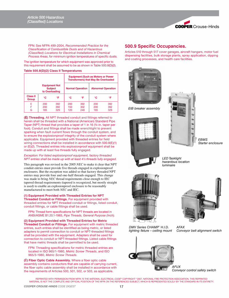
REPRINTED WITH PERMISSION FROM NFPA 70 THE NATIONAL ELECTRICAL CODE® COPYRIGHT © 2007, NATIONAL FIRE PROTECTION ASSOCIATION. THIS REPRINTED
MATERIAL IS NOT THE COMPLETE AND OFFICIAL POSITION OF THE NFPA ON THE REFERENCED SUBJECT, WHICH IS REPRESENTED SOLELY BY THE STANDARD IN ITS ENTIRETY.
17COOPER CROUSE-HINDS CODE DIGEST
FPN: See NFPA 499-2004, Recommended Practice for the Classification of Combustible Dusts and of Hazardous (Classified) Locations for Electrical Installations in Chemical Process Areas, for minimum ignition temperatures of specific dusts.
The ignition temperature for which equipment was approved prior to this requirement shall be assumed to be as shown in Table 500.8(D)(2).
Table 500.8(D)(2) Class II Temperatures
Equipment (Such as Motors or Power Transformers) that May Be Overloaded
Equipment Not Subject
to OverloadingNormal Operation Abnormal Operation
Class II Group
°C °F °C °F °C °F
EFG
200200165
392392329
200150120
392302248
200200165
392392329
(E) Threading. All NPT threaded conduit and fittings referred to herein shall be threaded with a National (American) Standard Pipe Taper (NPT) thread that provides a taper of 1 in 16 (¾-in. taper per foot). Conduit and fittings shall be made wrenchtight to prevent sparking when fault current flows through the conduit system, and to ensure the explosionproof integrity of the conduit system where applicable. Equipment provided with threaded entries for field wiring connections shall be installed in accordance with 500.8(E)(1) or (E)(2). Threaded entries into explosionproof equipment shall be made up with at least five threads fully engaged.
Exception: For listed explosionproof equipment, factory threaded NPT entries shall be made up with at least 4½ threads fully engaged.
This paragraph was revised in the 2005 NEC to make it clear that NPT conduit entries must provide five threads engaged in explosionproof enclosures. But the exception was added so that factory threaded NPT entries may provide four and one-half threads engaged. This change was made to bring NEC thread requirements close enough to IEC tapered thread requirements (tapered is recognized, but mostly straight is used) to enable an explosionproof enclosure to be reasonably manufactured to meet both NEC and IEC.
(1) Equipment Provided with Threaded Entries for NPT
Threaded Conduit or Fittings. For equipment provided with threaded entries for NPT threaded conduit or fittings, listed conduit, conduit fittings, or cable fittings shall be used.
FPN: Thread form specifications for NPT threads are located in ANSI/ASME B1.20.1-1983, Pipe Threads, General Purpose (Inch).
(2) Equipment Provided with Threaded Entries for Metric
Threaded Conduit or Fittings. For equipment with metric threaded entries, such entries shall be identified as being metric, or listed adapters to permit connection to conduit or NPT-threaded fittings shall be provided with the equipment. Adapters shall be used for connection to conduit or NPT-threaded fittings. Listed cable fittings that have metric threads shall be permitted to be used.
FPN: Threading specifications for metric threaded entries are located in ISO 965/1-1980, Metric Screw Threads, and ISO 965/3-1980, Metric Screw Threads.
(F) Fiber Optic Cable Assembly. Where a fiber optic cable assembly contains conductors that are capable of carrying current, the fiber optic cable assembly shall be installed in accordance with the requirements of Articles 500, 501, 502, or 503, as applicable.
500.9 Specific Occupancies.Articles 510 through 517 cover garages, aircraft hangars, motor fuel dispensing facilities, bulk storage plants, spray application, dipping and coating processes, and health care facilities.
EIB breaker assembly
EBMSStarter enclosure
LED Tasklight hazardous location luminaire
DMV Series CHAMP® H.I.D. lighting fixture – ceiling mount
AFAXConveyor belt alignment switch
AFUXConveyor control safety switch
Article 500 Hazardous(Classified) Locations
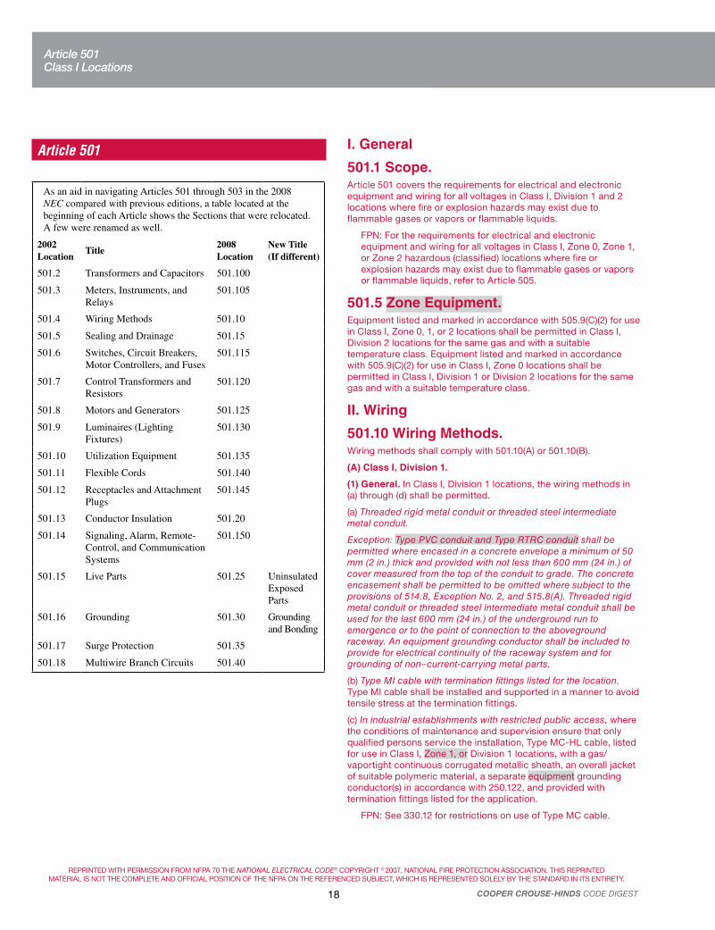
REPRINTED WITH PERMISSION FROM NFPA 70 THE NATIONAL ELECTRICAL CODE® COPYRIGHT © 2007, NATIONAL FIRE PROTECTION ASSOCIATION. THIS REPRINTED
MATERIAL IS NOT THE COMPLETE AND OFFICIAL POSITION OF THE NFPA ON THE REFERENCED SUBJECT, WHICH IS REPRESENTED SOLELY BY THE STANDARD IN ITS ENTIRETY.
18 COOPER CROUSE-HINDS CODE DIGEST
Article 501
As an aid in navigating Articles 501 through 503 in the 2008 NEC compared with previous editions, a table located at the beginning of each Article shows the Sections that were relocated. A few were renamed as well.
2002 Location
Title2008 Location
New Title (If different)
501.2 Transformers and Capacitors 501.100
501.3 Meters, Instruments, and Relays
501.105
501.4 Wiring Methods 501.10
501.5 Sealing and Drainage 501.15
501.6 Switches, Circuit Breakers, Motor Controllers, and Fuses
501.115
501.7 Control Transformers and Resistors
501.120
501.8 Motors and Generators 501.125
501.9 Luminaires (Lighting Fixtures)
501.130
501.10 Utilization Equipment 501.135
501.11 Flexible Cords 501.140
501.12 Receptacles and Attachment Plugs
501.145
501.13 Conductor Insulation 501.20
501.14 Signaling, Alarm, Remote-Control, and Communication Systems
501.150
501.15 Live Parts 501.25 Uninsulated Exposed Parts
501.16 Grounding 501.30 Grounding and Bonding
501.17 Surge Protection 501.35
501.18 Multiwire Branch Circuits 501.40
I. General
501.1 Scope.Article 501 covers the requirements for electrical and electronic equipment and wiring for all voltages in Class I, Division 1 and 2 locations where fire or explosion hazards may exist due to flammable gases or vapors or flammable liquids.
FPN: For the requirements for electrical and electronic equipment and wiring for all voltages in Class I, Zone 0, Zone 1, or Zone 2 hazardous (classified) locations where fire or explosion hazards may exist due to flammable gases or vapors or flammable liquids, refer to Article 505.
501.5 Zone Equipment.Equipment listed and marked in accordance with 505.9(C)(2) for use in Class I, Zone 0, 1, or 2 locations shall be permitted in Class I, Division 2 locations for the same gas and with a suitable temperature class. Equipment listed and marked in accordance with 505.9(C)(2) for use in Class I, Zone 0 locations shall be permitted in Class I, Division 1 or Division 2 locations for the same gas and with a suitable temperature class.
II. Wiring
501.10 Wiring Methods.Wiring methods shall comply with 501.10(A) or 501.10(B).
(A) Class I, Division 1.
(1) General. In Class I, Division 1 locations, the wiring methods in (a) through (d) shall be permitted.
(a) Threaded rigid metal conduit or threaded steel intermediate metal conduit.
Exception: Type PVC conduit and Type RTRC conduit shall be permitted where encased in a concrete envelope a minimum of 50 mm (2 in.) thick and provided with not less than 600 mm (24 in.) of cover measured from the top of the conduit to grade. The concrete encasement shall be permitted to be omitted where subject to the provisions of 514.8, Exception No. 2, and 515.8(A). Threaded rigid metal conduit or threaded steel intermediate metal conduit shall be used for the last 600 mm (24 in.) of the underground run to emergence or to the point of connection to the aboveground raceway. An equipment grounding conductor shall be included to provide for electrical continuity of the raceway system and for grounding of non–current-carrying metal parts.
(b) Type MI cable with termination fittings listed for the location. Type MI cable shall be installed and supported in a manner to avoid tensile stress at the termination fittings.
(c) In industrial establishments with restricted public access, where the conditions of maintenance and supervision ensure that only qualified persons service the installation, Type MC-HL cable, listed for use in Class I, Zone 1, or Division 1 locations, with a gas/vaportight continuous corrugated metallic sheath, an overall jacket of suitable polymeric material, a separate equipment grounding conductor(s) in accordance with 250.122, and provided with termination fittings listed for the application.
FPN: See 330.12 for restrictions on use of Type MC cable.
Article 501Class I Locations

REPRINTED WITH PERMISSION FROM NFPA 70 THE NATIONAL ELECTRICAL CODE® COPYRIGHT © 2007, NATIONAL FIRE PROTECTION ASSOCIATION. THIS REPRINTED
MATERIAL IS NOT THE COMPLETE AND OFFICIAL POSITION OF THE NFPA ON THE REFERENCED SUBJECT, WHICH IS REPRESENTED SOLELY BY THE STANDARD IN ITS ENTIRETY.
19COOPER CROUSE-HINDS CODE DIGEST
(3) Nonincendive Field Wiring. Nonincendive field wiring shall be permitted using any of the wiring methods permitted for unclassified locations. Nonincendive field wiring systems shall be installed in accordance with the control drawing(s). Simple apparatus, not shown on the control drawing, shall be permitted in a nonincendive field wiring circuit, provided the simple apparatus does not interconnect the nonincendive field wiring circuit to any other circuit.
FPN: Simple apparatus is defined in 504.2.
Separate nonincendive field wiring circuits shall be installed in accordance with one of the following:
(1) In separate cables
(2) In multiconductor cables where the conductors of each circuit are within a grounded metal shield
(3) In multiconductor cables, where the conductors of each circuit have insulation with a minimum thickness of 0.25 mm (0.01 in.)
(4) Boxes and Fittings. Boxes and fittings shall not be required to be explosionproof except as required by 501.105(B)(1), 501.115(B)(1), and 501.150(B)(1).
Wiring Methods Class I, Division 1.In Class I, Division 1 locations, all pull and junction boxes must be of a design suitable for such locations and threaded for rigid or IMC conduit. Type MI cable may be used and, under certain conditions, type MC-HL or ITC-HL cable may be used, all with listed cable fittings. Where necessary to use flexible connections, as at motor terminals, Class I, Division 1 flexible fittings must be used unless flexible cord is used in accordance with 501.140. A few of the many explosionproof fittings meeting the requirements of 501.10(A) are shown.
OEC Conduit body (Groups C, D)
EJB Junction box
(Groups B,C, D)
EAJX Conduit body (Groups A, B, C, D)
EBY Heavy-duty cord connector
Division 1 and Division 2 (Groups B, C, D)
(d) In industrial establishments with restricted public access, where the conditions of maintenance and supervision ensure that only qualified persons service the installation, Type ITC-HL cable, listed for use in Class I, Zone1, or Division 1 locations, with a gas/vaportight continuous corrugated metallic sheath, an overall jacket of suitable polymeric material and provided with termination fittings listed for the application.
FPN: See 727.4 and 727.5 for restrictions on use of Type ITC cable.
(2) Flexible Connections. Where necessary to employ flexible connections, as at motor terminals, flexible fittings listed for Class I, Division 1 locations or flexible cord in accordance with the provisions of 501.140 shall be permitted.
(3) Boxes and Fittings. All boxes and fittings shall be approved for Class I, Division 1.
(B) Class I, Division 2.
(1) General. In Class I, Division 2 locations, the following wiring methods shall be permitted:
(1) All wiring methods permitted in Article 501.10(A).
(2) Threaded rigid metal conduit, threaded steel intermediate metal conduit.
(3) Enclosed gasketed busways, enclosed gasketed wireways.
(4) Type PLTC cable in accordance with the provisions of Article 725, or in cable tray systems. PLTC shall be installed in a manner to avoid tensile stress at the termination fittings.
(5) Type ITC cable as permitted in 727.4.
(6) Type MI, MC, MV, or TC cable with termination fittings, or in cable tray systems and installed in a manner to avoid tensile stress at the termination fittings.
(7) In industrial establishments with restricted public access where the conditions of maintenance and supervision ensure that only qualified persons service the installation and where metallic conduit does not provide sufficient corrosion resistance, reinforced thermosetting resin conduit (RTRC), factory elbows, and associated fittings, all marked with the suffix -XW, and Schedule 80 PVC conduit, factory elbows, and associated fittings shall be permitted.
Where seals are required for boundary conditions as defined in 501.15(A)(4), the Division 1 wiring method shall extend into the Division 2 area to the seal, which shall be located on the Division 2 side of the Division 1–Division 2 boundary.
(2) Flexible Connections. Where provision must be made for limited flexibility, one or more of the following shall also be permitted:
(1) Flexible metal fittings.
(2) Flexible metal conduit with listed fittings.
(3) Liquidtight flexible metal conduit with listed fittings.
(4) Liquidtight flexible nonmetallic conduit with listed fittings.
(5) Flexible cord listed for extra-hard usage and provided with listed bushed fittings. A conductor for use as an equipment grounding conductor shall be included in the flexible cord.
FPN: See 501.30(B) for grounding requirements where flexible conduit is used.
Article 501Class I Locations

REPRINTED WITH PERMISSION FROM NFPA 70 THE NATIONAL ELECTRICAL CODE® COPYRIGHT © 2007, NATIONAL FIRE PROTECTION ASSOCIATION. THIS REPRINTED
MATERIAL IS NOT THE COMPLETE AND OFFICIAL POSITION OF THE NFPA ON THE REFERENCED SUBJECT, WHICH IS REPRESENTED SOLELY BY THE STANDARD IN ITS ENTIRETY.
20 COOPER CROUSE-HINDS CODE DIGEST
Liquidtight Conduit connectors
Liquidtight flexible conduit is sometimes permitted in Class I, Division 2 locations. When conductors contained in it are to enter or leave an explosionproof enclosure containing an arcing device, the liquidtight connector fitting should be connected to a sealing fitting (Type EYS or similar), which in turn is connected to the enclosure. Conductors are sealed in the sealing fitting in the normal manner. When used, this conduit must be grounded in accordance with Section 350.60 or 356.60 and 501.30.
501.15 Sealing and Drainage.Seals in conduit and cable systems shall comply with 501.15(A) through (F). Sealing compound shall be used in Type MI cable termination fittings to exclude moisture and other fluids from the cable insulation.
FPN No. 1: Seals are provided in conduit and cable systems to minimize the passage of gases and vapors and prevent the passage of flames from one portion of the electrical installation to another through the conduit. Such communication through Type MI cable is inherently prevented by construction of the cable. Unless specifically designed and tested for the purpose, conduit and cable seals are not intended to prevent the passage of liquids, gases, or vapors at a continuous pressure differential across the seal. Even at differences in pressure across the seal equivalent to a few inches of water, there may be a slow passage of gas or vapor through a seal and through conductors passing through the seal. See 501.15(E)(2). Temperature extremes and highly corrosive liquids and vapors can affect the ability of seals to perform their intended function. See 501.15(C)(2).
FPN No. 2: Gas or vapor leakage and propagation of flames may occur through the interstices between the strands of standard stranded conductors larger than 2 AWG. Special conductor constructions, for example, compacted strands or sealing of the individual strands, are means of reducing leakage and preventing the propagation of flames.
(A) Conduit Seals, Class I, Division 1. In Class I, Division 1 locations, conduit seals shall be located in accordance with 501.15(A)(1) through (A)(4).
(1) Entering Enclosures. In each conduit entry into an explosionproof enclosure where either of the following apply:
(1) The enclosure contains apparatus, such as switches, circuit breakers, fuses, relays, or resistors, that may produce arcs, sparks, or high temperatures that are considered to be an ignition source in normal operation.
(2) The entry is metric designator 53 (trade size 2) or larger and the enclosure contains terminals, splices, or taps.
For the purposes of this section, high temperatures shall be considered to be any temperatures exceeding 80 percent of the autoignition temperature in degrees Celsius of the gas or vapor involved.
ECGJH Flexible couplingLBH Conduit body
TMCX Terminator™ cable fittings for use with Type MC-HL or ITC-HL cable in Class I, Division 1 locations.
Wiring Methods Class I, Division 2.In Class I, Division 2 locations, either threaded rigid or steel IMC conduit, or enclosed and gasketed busways or wireways, or Type ITC, MI, MC, MV, TC, or PLTC cable with termination fittings approved for Class I locations must be used. Under certain restrictions, reinforced thermosetting resin conduit (RTRC) and Schedule 80 PVC conduit and associated fittings may be used. The junction and pull boxes need not be designed for Class I, Division 1 locations. A few of the many types of junction and pull boxes suitable for Division 2 locations (501.10(B)) are shown. Where provision must be made for limited flexibility, Type EBY heavy-duty cord connector may be used for both Division 1 and Division 2 locations.
Form 7, Form 8 or Mark 9 Conduit bodies
LB T C
WJB Junction box CGB Connector for portable cords and Types MV (unarmored), PLTC, SE (round), TC and UF cables
EBY Factory sealed flexible cord connector. May be used with flexible cord, where permitted, in Class I, Divisions 1 and 2 locations without a separate sealing fitting.
TMCX Terminator™ cable fittings for use with Type MC jacketed metal clad cables with interlocked or corrugated armor, or types ITC, TC or PLTC in Class I, Groups A, B, C, and D, Division 2 locations.
Article 501Class I Locations

REPRINTED WITH PERMISSION FROM NFPA 70 THE NATIONAL ELECTRICAL CODE® COPYRIGHT © 2007, NATIONAL FIRE PROTECTION ASSOCIATION. THIS REPRINTED
MATERIAL IS NOT THE COMPLETE AND OFFICIAL POSITION OF THE NFPA ON THE REFERENCED SUBJECT, WHICH IS REPRESENTED SOLELY BY THE STANDARD IN ITS ENTIRETY.
21COOPER CROUSE-HINDS CODE DIGEST
Exception to 501.15(A)(1)(1): Seals shall not be required for conduit entering an enclosure where such switches, circuit breakers, fuses, relays, or resistors comply with one of the following:
(1) Are enclosed within a chamber hermetically sealed against the entrance of gases or vapors
(2) Are immersed in oil in accordance with 501.115(B)(1)(2)
(3) Are enclosed within a factory-sealed explosionproof chamber located within the enclosure, identified for the location, and marked “factory sealed” or equivalent, unless the enclosure entry is metric designator 53 (trade size 2) or larger
(4) Are in nonincendive circuits
Factory-sealed enclosures shall not be considered to serve as a seal for another adjacent explosionproof enclosure that is required to have a conduit seal.
Conduit seals shall be installed within 450 mm (18 in.) from the enclosure. Only explosionproof unions, couplings, reducers, elbows, capped elbows, and conduit bodies similar to L, T, and Cross types that are not larger than the trade size of the conduit shall be permitted between the sealing fitting and the explosionproof enclosure.
(2) Pressurized Enclosures. In each conduit entry into a pressurized enclosure where the conduit is not pressurized as part of the protection system. Conduit seals shall be installed within 450 mm (18 in.) from the pressurized enclosure.
FPN No. 1: Installing the seal as close as possible to the enclosure will reduce problems with purging the dead airspace in the pressurized conduit.
FPN No. 2: For further information, see NFPA 496-2003, Standard for Purged and Pressurized Enclosures for Electrical Equipment.
(3) Two or More Explosionproof Enclosures. Where two or more explosionproof enclosures for which conduit seals are required under 501.15(A)(1) are connected by nipples or by runs of conduit not more than 900 mm (36 in.) long, a single conduit seal in each such nipple connection or run of conduit shall be considered sufficient if located not more than 450 mm (18 in.) from either enclosure.
(4) Class I, Division 1 Boundary. In each conduit run leaving a Class I, Division 1 location. The sealing fitting shall be permitted on either side of the boundary of such location within 3.05 m (10 ft) of the boundary and shall be designed and installed so as to minimize the amount of gas or vapor within the Division 1 portion of the conduit from being communicated to the conduit beyond the seal. Except for listed explosionproof reducers at the conduit seal, there shall be no union, coupling, box, or fitting between the conduit seal and the point at which the conduit leaves the Division 1 location.
Exception No. 1: Metal conduit that contains no unions, couplings, boxes, or fittings, and passes completely through a Class I, Division 1 location with no fittings less than 300 mm (12 in.) beyond each boundary, shall not require a conduit seal if the termination points of the unbroken conduit are in unclassified locations.
Exception No. 2: For underground conduit installed in accordance with 300.5 where the boundary is below grade, the sealing fitting shall be permitted to be installed after the conduit emerges from below grade, but there shall be no union, coupling, box, or fitting, other than listed explosionproof reducers at the sealing fitting, in the conduit between the sealing fitting and the point at which the conduit emerges from below grade.
(B) Conduit Seals, Class I, Division 2. In Class I, Division 2 locations, conduit seals shall be located in accordance with 501.15(B)(1) and (B)(2).
(1) Entering Enclosures. For connections to enclosures that are required to be explosionproof, a conduit seal shall be provided in accordance with 501.15(A)(1)(1) and (A)(3). All portions of the conduit run or nipple between the seal and such enclosure shall comply with 501.10(A).
(2) Class I, Division 2 Boundary. In each conduit run passing from a Class I, Division 2 location into an unclassified location. The sealing fitting shall be permitted on either side of the boundary of such location within 3.05 m (10 ft) of the boundary. Rigid metal conduit or threaded steel intermediate metal conduit shall be used between the sealing fitting and the point at which the conduit leaves the Division 2 location, and a threaded connection shall be used at the sealing fitting. Except for listed reducers at the conduit seal, there shall be no union, coupling, box, or fitting between the conduit seal and the point at which the conduit leaves the Division 2 location. Conduits shall be sealed to minimize the amount of gas or vapor within the Division 2 portion of the conduit from being communicated to the conduit beyond the seal. Such seals shall not be required to be explosionproof but shall be identified for the purpose of minimizing passage of gases under normal operating conditions and shall be accessible.
Exception No. 1: Metal conduit that contains no unions, couplings, boxes, or fittings, and passes completely through a Class I, Division 2 location with no fittings less than 300 mm (12 in.) beyond each boundary, shall not be required to be sealed if the termination points of the unbroken conduit are in unclassified locations.
Exception No. 2: Conduit systems terminating at an unclassified location where a wiring method transition is made to cable tray, cablebus, ventilated busway, Type MI cable, or cable not installed in any cable tray or raceway system, shall not be required to be sealed where passing from the Class I, Division 2 location into the unclassified location. The unclassified location shall be outdoors or, if the conduit system is all in one room, it shall be permitted to be indoors. The conduits shall not terminate at an enclosure containing an ignition source in normal operation.
Exception No. 3: Conduit systems passing from an enclosure or room that is unclassified as a result of pressurization into a Class I, Division 2 location shall not require a seal at the boundary.
FPN: For further information, refer to NFPA 496-2003, Standard for Purged and Pressurized Enclosures for Electrical Equipment.
Exception No. 4: Segments of aboveground conduit systems shall not be required to be sealed where passing from a Class I, Division 2 location into an unclassified location if all of the following conditions are met:
(1) No part of the conduit system segment passes through a Class I, Division 1 location where the conduit contains unions, couplings, boxes, or fittings within 300 mm (12 in.) of the Class I, Division 1 location.
(2) The conduit system segment is located entirely in outdoor locations.
(3) The conduit system segment is not directly connected to canned pumps, process or service connections for flow, pressure, or analysis measurement, and so forth, that depend on a single compression seal, diaphragm, or tube to prevent flammable or combustible fluids from entering the conduit system.
Article 501Class I Locations

REPRINTED WITH PERMISSION FROM NFPA 70 THE NATIONAL ELECTRICAL CODE® COPYRIGHT © 2007, NATIONAL FIRE PROTECTION ASSOCIATION. THIS REPRINTED
MATERIAL IS NOT THE COMPLETE AND OFFICIAL POSITION OF THE NFPA ON THE REFERENCED SUBJECT, WHICH IS REPRESENTED SOLELY BY THE STANDARD IN ITS ENTIRETY.
22 COOPER CROUSE-HINDS CODE DIGEST
(4) The conduit system segment contains only threaded metal conduit, unions, couplings, conduit bodies, and fittings in the unclassified location.
(5) The conduit system segment is sealed at its entry to each enclosure or fitting housing terminals, splices, or taps in Class I, Division 2 locations.
(C) Class I, Divisions 1 and 2. Seals installed in Class I, Division 1 and Division 2 locations shall comply with 501.15(C)(1) through (C)(6).
Exception: Seals not required to be explosionproof by 501.15(B)(2) or 504.70.
(1) Fittings. Enclosures for connections or equipment shall be provided with an integral means for sealing, or sealing fittings listed for the location shall be used. Sealing fittings shall be listed for use with one or more specific compounds and shall be accessible.
(2) Compound. The compound shall provide a seal against passage of gas or vapors through the seal fitting, shall not be affected by the surrounding atmosphere or liquids, and shall not have a melting point of less than 93°C (200°F).
(3) Thickness of Compounds. Except for listed cable sealing fittings, the thickness of the sealing compound in a completed seal shall not be less than the metric designator (trade size) of the sealing fitting expressed in the units of measurement employed, and in no case less than 16 mm (5/8-in.).
(4) Splices and Taps. Splices and taps shall not be made in fittings intended only for sealing with compound, nor shall other fittings in which splices or taps are made be filled with compound.
(5) Assemblies. In an assembly where equipment that may produce arcs, sparks, or high temperatures is located in a compartment separate from the compartment containing splices or taps, and an integral seal is provided where conductors pass from one compartment to the other, the entire assembly shall be identified for the location. Seals in conduit connections to the compartment containing splices or taps shall be provided in Class I, Division 1 locations where required by 501.15(A)(1)(2).
(6) Conductor Fill. The cross-sectional area of the conductors permitted in a seal shall not exceed 25 percent of the cross-sectional area of a rigid metal conduit of the same trade size unless it is specifically identified for a higher percentage of fill.
(D) Cable Seals, Class I, Division 1. In Class I, Division 1 locations, cable seals shall be located according to 501.15(D)(1) through (D)(3).
(1) At Terminations. Cable shall be sealed at all terminations. The sealing fitting shall comply with 501.15(C). Multiconductor Type MC-HL cables with a gas/vaportight continuous corrugated metallic sheath and an overall jacket of suitable polymeric material shall be sealed with a listed fitting after removing the jacket and any other covering so that the sealing compound surrounds each individual insulated conductor in such a manner as to minimize the passage of gases and vapors.
Exception: Shielded cables and twisted pair cables shall not require the removal of the shielding material or separation of the twisted pairs, provided the termination is by an approved means to minimize the entrance of gases or vapors and prevent propagation of flame into the cable core.
(2) Cables Capable of Transmitting Gases or Vapors. Cables in conduit with a gas/vaportight continuous sheath capable of transmitting gases or vapors through the cable core shall be sealed
in the Division 1 location after removing the jacket and any other coverings so that the sealing compound will surround each individual insulated conductor and the outer jacket.
Exception: Multiconductor cables with a gas/vaportight continuous sheath capable of transmitting gases or vapors through the cable core shall be permitted to be considered as a single conductor by sealing the cable in the conduit within 450 mm (18 in.) of the enclosure and the cable end within the enclosure by an approved means to minimize the entrance of gases or vapors and prevent the propagation of flame into the cable core, or by other approved methods. For shielded cables and twisted pair cables, it shall not be required to remove the shielding material or separate the twisted pair.
(3) Cables Incapable of Transmitting Gases or Vapors. Each multiconductor cable in conduit shall be considered as a single conductor if the cable is incapable of transmitting gases or vapors through the cable core. These cables shall be sealed in accordance with 501.15(A).
(E) Cable Seals, Class I, Division 2. In Class I, Division 2 locations, cable seals shall be located in accordance with 501.15(E)(1) through (E)(4).
(1) Terminations. Cables entering enclosures that are required to be explosionproof shall be sealed at the point of entrance. The sealing fitting shall comply with 501.15(B)(1). Multiconductor cables with a gas/vaportight continuous sheath capable of transmitting gases or vapors through the cable core shall be sealed in a listed fitting in the Division 2 location after removing the jacket and any other coverings so that the sealing compound surrounds each individual insulated conductor in such a manner as to minimize the passage of gases and vapors. Multiconductor cables in conduit shall be sealed as described in 501.15(D).
Exception No. 1: Cables passing from an enclosure or room that is unclassified as a result of Type Z pressurization into a Class I, Division 2 location shall not require a seal at the boundary.
Exception No. 2: Shielded cables and twisted pair cables shall not require the removal of the shielding material or separation of the twisted pairs, provided the termination is by an approved means to minimize the entrance of gases or vapors and prevent propagation of flame into the cable core.
(2) Cables That Do Not Transmit Gases or Vapors. Cables that have a gas/vaportight continuous sheath and do not transmit gases or vapors through the cable core in excess of the quantity permitted for seal fittings shall not be required to be sealed except as required in 501.15(E)(1). The minimum length of such cable run shall not be less than that length that limits gas or vapor flow through the cable core to the rate permitted for seal fittings [200 cm3/hr (0.007 ft3/hr) of air at a pressure of 1500 pascals (6 in. of water)].
FPN: The cable core does not include the interstices of the conductor strands.
(3) Cables Capable of Transmitting Gases or Vapors. Cables with a gas/vaportight continuous sheath capable of transmitting gases or vapors through the cable core shall not be required to be sealed except as required in 501.15(E)(1), unless the cable is attached to process equipment or devices that may cause a pressure in excess of 1500 pascals (6 in. of water) to be exerted at a cable end, in which case a seal, barrier, or other means shall be provided to prevent migration of flammables into an unclassified location.
Article 501Class I Locations

REPRINTED WITH PERMISSION FROM NFPA 70 THE NATIONAL ELECTRICAL CODE® COPYRIGHT © 2007, NATIONAL FIRE PROTECTION ASSOCIATION. THIS REPRINTED
MATERIAL IS NOT THE COMPLETE AND OFFICIAL POSITION OF THE NFPA ON THE REFERENCED SUBJECT, WHICH IS REPRESENTED SOLELY BY THE STANDARD IN ITS ENTIRETY.
23COOPER CROUSE-HINDS CODE DIGEST
Exception: Cables with an unbroken gas/vaportight continuous sheath shall be permitted to pass through a Class I, Division 2 location without seals.
(4) Cables Without Gas/Vaportight Sheath. Cables that do not have gas/vaportight continuous sheath shall be sealed at the boundary of the Division 2 and unclassified location in such a manner as to minimize the passage of gases or vapors into an unclassified location.
(F) Drainage.
(1) Control Equipment. Where there is a probability that liquid or other condensed vapor may be trapped within enclosures for control equipment or at any point in the raceway system, approved means shall be provided to prevent accumulation or to permit periodic draining of such liquid or condensed vapor.
(2) Motors and Generators. Where the authority having jurisdiction judges that there is a probability that liquid or condensed vapor may accumulate within motors or generators, joints and conduit systems shall be arranged to minimize the entrance of liquid. If means to prevent accumulation or to permit periodic draining are judged necessary, such means shall be provided at the time of manufacture and shall be considered an integral part of the machine.
(3) Canned Pumps, Process, or Service Connections, etc. For canned pumps, process, or service connections for flow, pressure, or analysis measurement, and so forth, that depend on a single compression seal, diaphragm, or tube to prevent flammable or combustible fluids from entering the electrical raceway or cable system capable of transmitting fluids, an additional approved seal, barrier, or other means shall be provided to prevent the flammable or combustible fluid from entering the raceway or cable system capable of transmitting fluids beyond the additional devices or means, if the primary seal fails. The additional approved seal or barrier and the interconnecting enclosure shall meet the temperature and pressure conditions to which they will be subjected upon failure of the primary seal, unless other approved means are provided to accomplish this purpose. Drains, vents, or other devices shall be provided so that primary seal leakage will be obvious.
FPN: See also the fine print notes to 501.15.
Process-connected equipment that is listed and marked “Dual Seal” shall not require additional process sealing when used within the manufacturer’s ratings.
Sealing Fittings:
of the electrical installation to another at atmospheric pressure and normal ambient temperatures.
Sealing Fittings are required for installation:
an arcing or sparking device when used in Class I, Division 1 and 2 classified hazardous areas. To be located as close as practicable and, in no case, more than 18 inches from such enclosures, or in accordance with the manufacturer's instructions.
ach entrance of 2-inch trade size or larger conduit entering an enclosure housing terminals, splices, or taps. To be located as close as practicable and, in no case, more than 18 inches from such enclosures, or in accordance with the manufacturer’s instructions.
classified hazardous locations.
vapors through the cable core and when these cables leave the Class I, Division 1 or Division 2 classified hazardous locations.
Note that in Division 2, the conduit between the seal and the explosionproof enclosure must be rigid or steel IMC conduit with threaded joints because threadless connections are not flame-tight (501.15(B)).
Factory-Sealed Units for Class I, Division 1 or 2 Hazardous Areas.Cooper Crouse-Hinds factory-sealed devices eliminate the time-consuming handwork of field-poured seals. The seal is designed into the device and it’s ready for installation as it comes from the box. No costly time is spent in damming the conduit run and mixing and pouring compounds. Installation is quick and easy. All the installer does is connect the pigtail leads or terminal screws on the back of the factory-sealed element to incoming wires, push the sealed device into the box and bolt down the cover.
Factory-sealed control stations include pushbutton stations, selector switches, tumbler switches, manual motor-starting switches, and pilot lights, all for surface mounting in single-gang or two-gang (EDS Series) housings and modular body assemblies (EDSCM Series). Add these to the present line of Cooper Crouse-Hinds factory-sealed control devices, panelboards, luminaires, plugs and receptacles, bell and horn signals and clocks, and you have the widest selection of factory-sealed devices available to meet your needs.
Cooper Crouse-Hinds offers an innovative method of factory sealing by utilizing an explosionproof contact block. Terminal connections/contacts are permanently molded, and sealed, into the device. The factory-sealed contact block mounts onto the cover by means of a mounting strap; cover and device can then be easily mounted on the backbox.
Compliances.These devices meet the NEC hazardous-area compliances for: Class I, Groups B (optional), C, D; Class II, Groups E, F, G; Class III areas; and NEMA 3, 7CD, 9EFG, and 12 requirements. Also UL Standards 894 and 698.
EFS/EDS Pushbutton selector switch
This factory-sealed control station requires field-installed seals on each hub only for EDS Class I, Group B Division 1 applications. Seals are not required for all other compliance applications.
Article 501Class I Locations

24 COOPER CROUSE-HINDS CODE DIGEST
EDS Factory sealed snap switch
In this factory-sealed unit the arcing device is completely enclosed and sealed, making it safe for use in hazardous areas. No external field-installed seals are required.
Factory-Sealed Delayed Action Circuit Breaking Plugs and Receptacles –Medium Duty.ARK-GARD® incorporates a spring loaded face plate in the receptacle. When engaged by the plug this plate moves forward and is rotated, closing the circuit. As rotation proceeds, the plug becomes locked in the receptacle and cannot be withdrawn until this procedure is reversed. In making or breaking the circuit, any resulting electrical arc is confined in a sealed chamber.
The factory-sealed chamber encloses the arcing components between two explosionproof threaded joints. These joints are coated to guarantee against seizure between the receptacle insert and housing.
ENR Receptacle with ENP Plug
Factory-Sealed Industrial Heavy-Duty Plugs and Receptacles.
CPS Delayed action
circuit breaking
receptacle 20-30 amp.
CES Delayed action
circuit breaking
receptacle 30-60 amp.
To connect portable or movable electrical equipment, such as motors, motor-generator sets, tools, or lighting systems.
Factory-Sealed Control Stations.For remote and local motor control and visual indication. A wide selection of pushbuttons, snap and selector switches, and pilot lights for surface and panel mounting are available.
EDSCM Control device bodies are available for surface mounting of factory-sealed control stations. Up to five 1, 2, or 3-gang body modules can be joined together without an intervening seal, thus providing mounting for up to 15 control devices.
Factory-Sealed Units for Class I, Division 2 Hazardous Areas.Cooper Crouse-Hinds N2S and N2SC factory-sealed pushbutton stations, selector switches, and pilot lights meet the NEC requirements for Class I, Division 2, Groups B, C, D; and NEMA types 3, 4X, 7BCD (Division 2), and 12; also UL Standard 698.
External seals are not required. N2S/N2SC pushbutton stations and selector switches are explosionproof. A closed-ended labyrinth contact block assures a factory-sealed device.
N2SU ESWP Control station factory-sealed contact block
In this factory-sealed control station the arcing device is explosionproof, making it safe for use in Class I, Division 2, Groups B, C, and D hazardous areas. No external field installed seals are required.
EDSC front-operated pushbutton
EDSC Selector switch, surface mounting
EDSC Pushbutton with side rocker handle
Article 501Class I Locations

25COOPER CROUSE-HINDS CODE DIGEST
Factory-Sealed Power Switch.
The RSWP factory-sealed motor control switch also eliminates the need for seals in most applications. It is available in non-metallic enclosures and receptacles for Division 2 applications, such as the N2RS Industrial Control Switch.
Factory-Sealed Panelboards.
LP Panel
Two types of factory-sealed panelboards are used for central control and protection for large numbers of feeders and branch circuits and for housing circuit breakers. An example of the type suitable for Division 2 is the D2PB, in which each branch circuit breaker is explosionproof, eliminating the need for an overall explosionproof enclosure and the associated conduit seals. The optional main breaker is housed in a separate explosionproof enclosure which is isolated by a seal installed at the factory. This type of panelboard is also available in a nonmetallic version, the N2PB.
The second type is used for both Division 1 and 2 applications and is illustrated by Cooper Crouse-Hinds LP panelboard. The circuit breaker housing is explosionproof since the individual breakers, including the main, are not. All field wiring, however, is done in a separate wiring compartment with all leads between the two sections being sealed at the factory. It is interesting to note that, while the NEC uses the term “factory-sealed” it is also known as the “indirect entry” method.
D2L Panelboard with inverted option
Field Sealing Fittings.For sealing conduit 2-inch trade size or larger in accordance with 501.5(A)(1), and for sectionalizing long runs of conduit to eliminate pressure piling, several types of sealing fittings are available. These include EYS seals for vertical or horizontal conduit runs; EZS for sealing conduit at any angle; EYD and EZD drain seals for vertical conduit runs; and EZD inspection seals.
If water accumulation is possible in horizontal conduit runs, conduit should be graded away from seals to enclosures where ECD breather drains can be installed.
Note: Information on “Selection of Seals and Drains” and an “Installation Diagram for Sealing” may be found in Appendices III and IV.
Field Sealing Fittings.
For sealing in vertical or horizontal positions EYS 1/2-6 inches
For retro fit sealing EYSR 3/4-4 inches
For sealing at any angle EZS 1/2-3 inches
For vertical conduit only
EYD Drain Seal 1/2-1 inch EYD Drain Seal 1 1/4-4inch
Article 501Class I Locations

26 COOPER CROUSE-HINDS CODE DIGEST
EZD with drain inspection cover
“Standard” ECD breather drain
“Standard” ECD drain
Type 4X drain
“Universal” ECD breather or drain
Type 4X breather
Combination ECD breather and drain
EYSX EYDX
An alternative to the traditional sealing fitting is shown below. It is a conduit outlet box that can be fitted with a sealing cover. These are available in a variety of hub arrangements, can be installed vertically or horizontally, and have ample room and access for the maximum allowable forty percent wire fill.
GUAT outlet box GUA sealing cover
An exception to 501.15(D)(2) for multiconductor cables in conduit permits them to be sealed, in an EYS for example, as an individual conductor with the cable end in the enclosure being sealed by an approved means such as Cooper Crouse-Hinds TSC epoxy sealing compound. This eliminates the difficult task of removing the jacket and sealing around the individual conductors in the sealing fitting.
TSC ES sealing hub
The TSC compound can also be used with Cooper Crouse-Hinds’ ES sealing hub shown above. While the ES was originally designed for use with the poured CHICO compound, using it with the TSC sealing compound allows the sealing hub to be used in any orientation, side or top, as well as bottom.
Receptacles and Attachment Plugs, Class I, Divisions 1 and 2.To be safe for use in Class I, Division 1 or Division 2 locations, arcing at exposed contacts must be prevented. This may be achieved in two ways: (1) by enclosing the mating parts of plug and receptacle in a chamber designed for use in these locations and by a delayed action construction which prevents complete removal of the plug until the flame, sparks, or hot metal have cooled before final withdrawal of the plug; or (2) by interlocking the plug with a properly enclosed switch whereby the mating parts are de-energized when the plug is inserted or withdrawn. Either method may be used to comply with 501.145.
NPJ Plug
W2SR Interlocked Arktite® receptacle
Article 501Class I Locations
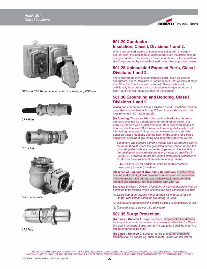
REPRINTED WITH PERMISSION FROM NFPA 70 THE NATIONAL ELECTRICAL CODE® COPYRIGHT © 2007, NATIONAL FIRE PROTECTION ASSOCIATION. THIS REPRINTED
MATERIAL IS NOT THE COMPLETE AND OFFICIAL POSITION OF THE NFPA ON THE REFERENCED SUBJECT, WHICH IS REPRESENTED SOLELY BY THE STANDARD IN ITS ENTIRETY.
27COOPER CROUSE-HINDS CODE DIGEST
GFS and CPS Receptacle mounted in a two-gang EDS box
CPP Plug
CPH Plug
FSQC receptacle
APJ Plug
501.20 Conductor Insulation, Class I, Divisions 1 and 2.Where condensed vapors or liquids may collect on, or come in contact with, the insulation on conductors, such insulation shall be of a type identified for use under such conditions; or the insulation shall be protected by a sheath of lead or by other approved means.
501.25 Uninsulated Exposed Parts, Class I, Divisions 1 and 2.There shall be no uninsulated exposed parts, such as electric conductors, buses, terminals, or components, that operate at more than 30 volts (15 volts in wet locations). These parts shall additionally be protected by a protection technique according to 500.7(E), (F), or (G) that is suitable for the location.
501.30 Grounding and Bonding, Class I, Divisions 1 and 2.Wiring and equipment in Class I, Division 1 and 2 locations shall be grounded as specified in Article 250 and in accordance with the requirements in 501.30(A) and (B).
(A) Bonding. The locknut-bushing and double-locknut types of contacts shall not be depended on for bonding purposes, but bonding jumpers with proper fittings or other approved means of bonding shall be used. Such means of bonding shall apply to all intervening raceways, fittings, boxes, enclosures, and so forth between Class I locations and the point of grounding for service equipment or point of grounding of a separately derived system.
Exception: The specific bonding means shall be required only to the nearest point where the grounded circuit conductor and the grounding electrode are connected together on the line side of the building or structure disconnecting means as specified in 250.32(B), provided the branch-circuit overcurrent protection is located on the load side of the disconnecting means.
FPN: See 250.100 for additional bonding requirements in hazardous (classified) locations.
(B) Types of Equipment Grounding Conductors. Flexible metal conduit and liquidtight flexible metal conduit shall not be used as the sole ground-fault current path. Where equipment bonding jumpers are installed, they shall comply with 250.102.
Exception: In Class I, Division 2 locations, the bonding jumper shall be permitted to be deleted where all of the following conditions are met:
(1) Listed liquidtight flexible metal conduit 1.8 m (6 ft) or less in length, with fittings listed for grounding, is used.
(2) Overcurrent protection in the circuit is limited to 10 amperes or less.
(3) The load is not a power utilization load.
501.35 Surge Protection.(A) Class I, Division 1. Surge arresters, surge-protective devices, and capacitors shall be installed in enclosures identified for Class I, Division 1 locations. Surge-protective capacitors shall be of a type designed for specific duty.
(B) Class I, Division 2. Surge arresters and surge-protective devices shall be nonarcing, such as metal-oxide varistor (MOV)
Article 501Class I Locations

REPRINTED WITH PERMISSION FROM NFPA 70 THE NATIONAL ELECTRICAL CODE® COPYRIGHT © 2007, NATIONAL FIRE PROTECTION ASSOCIATION. THIS REPRINTED
MATERIAL IS NOT THE COMPLETE AND OFFICIAL POSITION OF THE NFPA ON THE REFERENCED SUBJECT, WHICH IS REPRESENTED SOLELY BY THE STANDARD IN ITS ENTIRETY.
28 COOPER CROUSE-HINDS CODE DIGEST
sealed type, and surge-protective capacitors shall be of a type designed for specific duty. Enclosures shall be permitted to be of the general-purpose type. Surge protection of types other than described in this paragraph shall be installed in enclosures identified for Class I, Division 1 locations.
501.40 Multiwire Branch Circuits.In a Class I, Division 1 location, a multiwire branch circuit shall not be permitted.
Exception: Where the disconnect device(s) for the circuit opens all ungrounded conductors of the multiwire circuit simultaneously.
III. Equipment
501.100 Transformers and Capacitors.(A) Class I, Division 1. In Class I, Division 1 locations, transformers and capacitors shall comply with 501.100(A)(1) and (A)(2).
(1) Containing Liquid That Will Burn. Transformers and capacitors containing a liquid that will burn shall be installed only in vaults that comply with 450.41 through 450.48 and with (1) through (4) as follows:
(1) There shall be no door or other communicating opening between the vault and the Division 1 location.
(2) Ample ventilation shall be provided for the continuous removal of flammable gases or vapors.
(3) Vent openings or ducts shall lead to a safe location outside of buildings.
(4) Vent ducts and openings shall be of sufficient area to relieve explosion pressures within the vault, and all portions of vent ducts within the buildings shall be of reinforced concrete construction.
(2) Not Containing Liquid That Will Burn. Transformers and capacitors that do not contain a liquid that will burn shall be installed in vaults complying with 501.100(A)(1) or be identified for Class I locations.
(B) Class I, Division 2. In Class I, Division 2 locations, transformers and capacitors shall comply with 450.21 through 450.27.
501.105 Meters, Instruments, and Relays.(A) Class I, Division 1. In Class I, Division 1 locations, meters, instruments, and relays, including kilowatt-hour meters, instrument transformers, resistors, rectifiers, and thermionic tubes, shall be provided with enclosures identified for Class I, Division 1 locations. Enclosures for Class I, Division 1 locations include explosionproof enclosures and purged and pressurized enclosures.
FPN: See NFPA 496-2003, Standard for Purged and Pressurized Enclosures for Electrical Equipment.
(B) Class I, Division 2. In Class I, Division 2 locations, meters, instruments, and relays shall comply with 501.105(B)(1) through (B)(6).
(1) Contacts. Switches, circuit breakers, and make-and-break contacts of pushbuttons, relays, alarm bells, and horns shall have enclosures identified for Class I, Division 1 locations in accordance with 501.105(A).
Exception: General-purpose enclosures shall be permitted if current-interrupting contacts comply with one of the following:
(1) Are immersed in oil
(2) Are enclosed within a chamber that is hermetically sealed against the entrance of gases or vapors
(3) Are in nonincendive circuits
(4) Are listed for Division 2
(2) Resistors and Similar Equipment. Resistors, resistance devices, thermionic tubes, rectifiers, and similar equipment that are used in or in connection with meters, instruments, and relays shall comply with 501.105(A).
Exception: General-purpose-type enclosures shall be permitted if such equipment is without make-and-break or sliding contacts [other than as provided in 501.105(B)(1)] and if the maximum operating temperature of any exposed surface will not exceed 80 percent of the ignition temperature in degrees Celsius of the gas or vapor involved or has been tested and found incapable of igniting the gas or vapor. This exception shall not apply to thermionic tubes.
(3) Without Make-or-Break Contacts. Transformer windings, impedance coils, solenoids, and other windings that do not incorporate sliding or make-or-break contacts shall be provided with enclosures. General-purpose-type enclosures shall be permitted.
(4) General-Purpose Assemblies. Where an assembly is made up of components for which general-purpose enclosures are acceptable as provided in 501.105(B)(1), (B)(2), and (B)(3), a single general-purpose enclosure shall be acceptable for the assembly. Where such an assembly includes any of the equipment described in 501.105(B)(2), the maximum obtainable surface temperature of any component of the assembly shall be clearly and permanently indicated on the outside of the enclosure. Alternatively, equipment shall be permitted to be marked to indicate the temperature class for which it is suitable, using the temperature class (T Code) of Table 500.8(C).
(5) Fuses. Where general-purpose enclosures are permitted in 501.105(B)(1) through (B)(4), fuses for overcurrent protection of instrument circuits not subject to overloading in normal use shall be permitted to be mounted in general-purpose enclosures if each such fuse is preceded by a switch complying with 501.105(B)(1).
(6) Connections. To facilitate replacements, process control instruments shall be permitted to be connected through flexible cord, attachment plug, and receptacle, provided all of the following conditions apply:
(1) A switch complying with 501.105(B)(1) is provided so that the attachment plug is not depended on to interrupt current.
(2) The current does not exceed 3 amperes at 120 volts, nominal.
(3) The power-supply cord does not exceed 900 mm (3 ft), is of a type listed for extra-hard usage or for hard usage if protected by location, and is supplied through an attachment plug and receptacle of the locking and grounding type.
(4) Only necessary receptacles are provided.
(5) The receptacle carries a label warning against unplugging under load.
Article 501Class I Locations

REPRINTED WITH PERMISSION FROM NFPA 70 THE NATIONAL ELECTRICAL CODE® COPYRIGHT © 2007, NATIONAL FIRE PROTECTION ASSOCIATION. THIS REPRINTED
MATERIAL IS NOT THE COMPLETE AND OFFICIAL POSITION OF THE NFPA ON THE REFERENCED SUBJECT, WHICH IS REPRESENTED SOLELY BY THE STANDARD IN ITS ENTIRETY.
29COOPER CROUSE-HINDS CODE DIGEST
(4) The device is a solid state, switching control without contacts, where the surface temperature does not exceed 80 percent of the ignition temperature in degrees Celsius of the gas or vapor involved.
(2) Isolating Switches. Fused or unfused disconnect and isolating switches for transformers or capacitor banks that are not intended to interrupt current in the normal performance of the function for which they are installed shall be permitted to be installed in general-purpose enclosures.
(3) Fuses. For the protection of motors, appliances, and lamps, other than as provided in 501.115(B)(4), standard plug or cartridge fuses shall be permitted, provided they are placed within enclosures identified for the location; or fuses shall be permitted if they are within general-purpose enclosures, and if they are of a type in which the operating element is immersed in oil or other approved liquid, or the operating element is enclosed within a chamber hermetically sealed against the entrance of gases and vapors, or the fuse is a nonindicating, filled, current-limiting type.
(4) Fuses Internal to Luminaires. Listed cartridge fuses shall be permitted as supplementary protection within luminaires.
GUSC With switch or circuit breaker with external handle lock on or off position.
Switches, Circuit-Breakers, Ground Fault Circuit Interrupters, Controllers, Panelboards, etc. Class I, Divisions 1 and 2.Exposed arcs in locations which are hazard-ous because of flammable gases or vapors are a positive source of ignition. Because switches, circuit breakers, motor controllers, relays, fuses, etc. produce arcs, safety requires that these arcs be rendered harmless. This objective can be accomplished by placing all arcing devices in cast metal enclosures designed for use in hazardous locations. These enclosures will withstand the force of any internal explosions which may occur and are tight enough to prevent passage, through joints, of flames or gases hot enough to ignite the surrounding atmospheres. Therefore, explosions which occur due to arcs are confined within the enclosures.
Hazardous location enclosures for arcing devices are required for both Division 1 and Division 2. Exceptions are permitted in Division 2 as stated in 501.115(B).
Meters, Instruments, and RelaysClass I, Divisions 1 and 2.GUB and EIH hazardous location (Class I) enclosures are for meters or other instruments that must be visible to an observer.
TCH Electric clock EIH Instrument enclosures
GUB with flat cover
GUB Junction boxes are suitable for use in Class I, Division 1 and 2 locations and provide convenient means for making branch circuit taps from main feeders. When gasketed, GUB junction boxes are ideal for outdoor use.
Note:
Appendices V through X.
Appendix XI.
501.115 Switches, Circuit Breakers, Motor Controllers, and Fuses.(A) Class I, Division 1. In Class I, Division 1 locations, switches, circuit breakers, motor controllers, and fuses, including pushbuttons, relays, and similar devices, shall be provided with enclosures, and the enclosure in each case, together with the enclosed apparatus, shall be identified as a complete assembly for use in Class I locations.
(B) Class I, Division 2. Switches, circuit breakers, motor controllers, and fuses in Class I, Division 2 locations shall comply with 501.115(B)(1) through (B)(4).
(1) Type Required. Circuit breakers, motor controllers, and switches intended to interrupt current in the normal performance of the function for which they are installed shall be provided with enclosures identified for Class I, Division 1 locations in accordance with 501.105(A), unless general-purpose enclosures are provided and any of the following apply:
(1) The interruption of current occurs within a chamber hermetically sealed against the entrance of gases and vapors.
(2) The current make-and-break contacts are oil-immersed and of the general-purpose type having a 50-mm (2-in.) minimum immersion for power contacts and a 25-mm (1-in.) minimum immersion for control contacts.
(3) The interruption of current occurs within a factory-sealed explosionproof chamber.
Article 501Class I Locations

REPRINTED WITH PERMISSION FROM NFPA 70 THE NATIONAL ELECTRICAL CODE® COPYRIGHT © 2007, NATIONAL FIRE PROTECTION ASSOCIATION. THIS REPRINTED
MATERIAL IS NOT THE COMPLETE AND OFFICIAL POSITION OF THE NFPA ON THE REFERENCED SUBJECT, WHICH IS REPRESENTED SOLELY BY THE STANDARD IN ITS ENTIRETY.
30 COOPER CROUSE-HINDS CODE DIGEST
EBMC Series motor control enclosure with combination line starter
EJB Control panel
EIB Breaker assembly
GFS-1 Ground fault circuit interrupter
EFS Pushbutton station
EVLP Lo-Pro Hazard-Gard fixture
PowerPlus™ Panelboards are fully wired for breakers and additional spaces. Factory-sealed Multi-Sleeve Modules™ are removable, so conductors can be replaced and retain third-party approval.
501.120 Control Transformers and Resistors.Transformers, impedance coils, and resistors used as, or in conjunction with, control equipment for motors, generators, and appliances shall comply with 501.120(A) and (B).
(A) Class I, Division 1. In Class I, Division 1 locations, transformers, impedance coils, and resistors, together with any switching mechanism associated with them, shall be provided with enclosures identified for Class I, Division 1 locations in accordance with 501.105(A).
(B) Class I, Division 2. In Class I, Division 2 locations, control transformers and resistors shall comply with 501.120(B)(1) through (B)(3).
(1) Switching Mechanisms. Switching mechanisms used in conjunction with transformers, impedance coils, and resistors shall comply with 501.115(B).
(2) Coils and Windings. Enclosures for windings of transformers, solenoids, or impedance coils shall be permitted to be of the general-purpose type.
(3) Resistors. Resistors shall be provided with enclosures; and the assembly shall be identified for Class I locations, unless resistance is nonvariable and maximum operating temperature, in degrees Celsius, will not exceed 80 percent of the ignition temperature of the gas or vapor involved or has been tested and found incapable of igniting the gas or vapor.
D2Z SpecOne™ Panelboard
Article 501Class I Locations

REPRINTED WITH PERMISSION FROM NFPA 70 THE NATIONAL ELECTRICAL CODE® COPYRIGHT © 2007, NATIONAL FIRE PROTECTION ASSOCIATION. THIS REPRINTED
MATERIAL IS NOT THE COMPLETE AND OFFICIAL POSITION OF THE NFPA ON THE REFERENCED SUBJECT, WHICH IS REPRESENTED SOLELY BY THE STANDARD IN ITS ENTIRETY.
31COOPER CROUSE-HINDS CODE DIGEST
501.125 Motors and Generators.(A) Class I, Division 1. In Class I, Division 1 locations, motors, generators, and other rotating electric machinery shall be one of the following:
(1) Identified for Class I, Division 1 locations
(2) Of the totally enclosed type supplied with positive-pressure ventilation from a source of clean air with discharge to a safe area, so arranged to prevent energizing of the machine until ventilation has been established and the enclosure has been purged with at least 10 volumes of air, and also arranged to automatically de-energize the equipment when the air supply fails
(3) Of the totally enclosed inert gas-filled type supplied with a suitable reliable source of inert gas for pressurizing the enclosure, with devices provided to ensure a positive pressure in the enclosure and arranged to automatically de-energize the equipment when the gas supply fails
(4) Of a type designed to be submerged in a liquid that is flammable only when vaporized and mixed with air, or in a gas or vapor at a pressure greater than atmospheric and that is flammable only when mixed with air; and the machine is so arranged to prevent energizing it until it has been purged with the liquid or gas to exclude air, and also arranged to automatically de-energize the equipment when the supply of liquid or gas or vapor fails or the pressure is reduced to atmospheric
Totally enclosed motors of the types specified in 501.125(A)(2) or (A)(3) shall have no external surface with an operating temperature in degrees Celsius in excess of 80 percent of the ignition temperature of the gas or vapor involved. Appropriate devices shall be provided to detect and automatically de-energize the motor or provide an adequate alarm if there is any increase in temperature of the motor beyond designed limits. Auxiliary equipment shall be of a type identified for the location in which it is installed.
FPN: See D 2155-69, ASTM Test Procedure.
(B) Class I, Division 2. In Class I, Division 2 locations, motors, generators, and other rotating electric machinery in which are employed sliding contacts, centrifugal or other types of switching mechanism (including motor overcurrent, overloading, and overtemperature devices), or integral resistance devices, either while starting or while running, shall be identified for Class I, Division 1 locations, unless such sliding contacts, switching mechanisms, and resistance devices are provided with enclosures identified for Class I, Division 2 locations in accordance with 501.105(B). The exposed surface of space heaters used to prevent condensation of moisture during shutdown periods shall not exceed 80 percent of the ignition temperature in degrees Celsius of the gas or vapor involved when operated at rated voltage, and the maximum surface temperature [based on a 40°C (104°F) ambient] shall be permanently marked on a visible nameplate mounted on the motor. Otherwise, space heaters shall be identified for Class I, Division 2 locations. In Class I, Division 2 locations, the installation of open or nonexplosionproof enclosed motors, such as squirrel-cage induction motors without brushes, switching mechanisms, or similar arc-producing devices that are not identified for use in a Class I, Division 2 location, shall be permitted.
FPN No. 1: It is important to consider the temperature of internal and external surfaces that may be exposed to the flammable atmosphere.
FPN No. 2: It is important to consider the risk of ignition due to currents arcing across discontinuities and overheating of parts in multisection enclosures of large motors and generators. Such motors and generators may need equipotential bonding jumpers across joints in the enclosure and from enclosure to ground. Where the presence of ignitible gases or vapors is suspected, clean-air purging may be needed immediately prior to and during start-up periods.
FPN No. 3: For further information on the application of electric motors in Class I, Division 2 hazardous (classified) locations, see IEEE Std. 1349-2001, IEEE Guide for the Application of Electric Motors in Class I, Division 2 Hazardous (Classified) Locations.
501.130 Luminaires.Luminaires shall comply with 501.130(A) or (B).
(A) Class I, Division 1. In Class I, Division 1 locations, luminaires shall comply with 501.130(A)(1) through (A)(4).
(1) Luminaires. Each luminaire shall be identified as a complete assembly for the Class I, Division 1 location and shall be clearly marked to indicate the maximum wattage of lamps for which it is identified. Luminaires intended for portable use shall be specifically listed as a complete assembly for that use.
(2) Physical Damage. Each luminaire shall be protected against physical damage by a suitable guard or by location.
EVLP Lo-Pro Hazard-Gard fixture
Article 501Class I Locations

REPRINTED WITH PERMISSION FROM NFPA 70 THE NATIONAL ELECTRICAL CODE® COPYRIGHT © 2007, NATIONAL FIRE PROTECTION ASSOCIATION. THIS REPRINTED
MATERIAL IS NOT THE COMPLETE AND OFFICIAL POSITION OF THE NFPA ON THE REFERENCED SUBJECT, WHICH IS REPRESENTED SOLELY BY THE STANDARD IN ITS ENTIRETY.
32 COOPER CROUSE-HINDS CODE DIGEST
3) Pendant Luminaires. Pendant luminaires shall be suspended by and supplied through threaded rigid metal conduit stems or threaded steel intermediate conduit stems, and threaded joints shall be provided with set-screws or other effective means to prevent loosening. For stems longer than 300 mm (12 in.), permanent and effective bracing against lateral displacement shall be provided at a level not more than 300 mm (12 in.) above the lower end of the stem, or flexibility in the form of a fitting or flexible connector identified for the Class I, Division 1 location shall be provided not more than 300 mm (12 in.) from the point of attachment to the supporting box or fitting.
(4) Supports. Boxes, box assemblies, or fittings used for the support of luminaires shall be identified for Class I locations.
(B) Class I, Division 2. In Class I, Division 2 locations, luminaires shall comply with 501.130(B)(1) through (B)(6).
(1) Luminaires. Where lamps are of a size or type that may, under normal operating conditions, reach surface temperatures exceeding 80 percent of the ignition temperature in degrees Celsius of the gas or vapor involved, luminaires shall comply with 501.130(A)(1) or shall be of a type that has been tested in order to determine the marked operating temperature or temperature class (T Code).
(2) Physical Damage. Luminaires shall be protected from physical damage by suitable guards or by location. Where there is danger that falling sparks or hot metal from lamps or fixtures might ignite localized concentrations of flammable vapors or gases, suitable enclosures or other effective protective means shall be provided.
(3) Pendant Luminaires. Pendant luminaires shall be suspended by threaded rigid metal conduit stems, threaded steel intermediate metal conduit stems, or other approved means. For rigid stems longer than 300 mm (12 in.), permanent and effective bracing against lateral displacement shall be provided at a level not more than 300 mm (12 in.) above the lower end of the stem, or flexibility in the form of an identified fitting or flexible connector shall be provided not more than 300 mm (12 in.) from the point of attachment to the supporting box or fitting.
(4) Portable Lighting Equipment. Portable lighting equipment shall comply with 501.130(A)(1).
Exception: Where portable lighting equipment is mounted on movable stands and is connected by flexible cords, as covered in 501.140, it shall be permitted, where mounted in any position, if it conforms to 501.130(B)(2).
(5) Switches. Switches that are a part of an assembled fixture or of an individual lampholder shall comply with 501.115(B)(1).
(6) Starting Equipment. Starting and control equipment for electric-discharge lamps shall comply with 501.120(B).
Exception: A thermal protector potted into a thermally protected fluorescent lamp ballast if the luminaire is identified for the location.
Luminaires Class I, Division 1.In locations where explosive gases or vapors exist, bare lamps or nonexplosionproof enclosed luminaires constitute hazards. Bare lamps may be broken, thereby causing explosions. For this reason, such lamps must be enclosed in luminaires designed for Class I, Division 1 locations (501.130(A)). Cooper Crouse-Hinds EVI Series luminaires are designed to provide easy installation, easy maintenance, and high efficiency; many types are available. Handlamps and a number of special-purpose luminaires are also available in Class I, Division 1 design.
In hazardous locations of all classes, pendant-mounted luminaires must be suspended by flexible hangers unless rigid stems not over 12 inches long are used, or longer stems are permanently braced within 12 inches of the luminaire.
A variety of installations that meet Code requirements are shown. EAHC, with Crouse-Hinds EV Series luminaires are designed for Group A and B locations. Any combination of the other boxes, covers and stems, or flexible coupling shown with appropriate luminaire is suitable for Class I, Groups C and D.
Note: Diagrams for Class I Lighting Installations appear in Appendix VI.
appears in Appendix XI.
EVI Series luminaire – Incandescent
EVF Fluorescent luminaire
The Illuminator™ EVFT four lamp fixture, utilizes the latest single-ended fluorescent lamp technology
Article 501Class I Locations

33COOPER CROUSE-HINDS CODE DIGEST
Luminaires Class I, Division 2.In locations which are classified Class I, Division 2, fixed luminaires
which have been tested may operate up to the ignition temperature of
the gas or vapor involved. Since it is assumed that a flammable vapor
can find its way into the luminaire, this temperature is measured at the
hottest accessible point, typically the lamp surface.
Another type of luminaire suitable for Class I, Division 2 has an
operating temperature that is measured on its outside surface, resulting
in a significantly lower temperature and, therefore, T-rating than that of
the lamp. The type of protection is called “restricted breathing” and
was originally developed for Zone 2 applications. Since the NEC, in
501.5, permits equipment rated for Zones to be used in Division 2, this
type of luminaire may be used in this application.
The principle of restricted breathing involves making sure a flammable
vapor is not able to enter the enclosure, which means that any conduit
entries must be sealed as part of the installation. The method of sealing
is not required to be explosionproof and is covered by the installation
instructions.
Taking this another step forward is a luminaire that incorporates another
Zone 2 protection technique as well: “non-arcing.” While the lamp
compartment is “restricted-breathing,” the ballast compartment is
“non-arcing” and there is a factory-installed seal between the two. This
eliminates the need for any field installed seals. See figure below.
Cooper Crouse-Hinds will supply specific information on operating
temperatures of its luminaires on request.
Note: A “Quick Selector” Guide for Class I, Division 2 electrical equipment appears in Appendix XI. Diagrams for Class I Lighting Installations appear in Appendix VI.
Cooper Crouse-Hinds luminaires are certified as ExnR “restricted breathing” for Division 2 locations
VAPORGARD™ Iuminaires in oil refinery
Pendant luminaire hangers
GUACCPSEAJCCPS GUATEACH and EFHC
COUP
Union Hub Cover
12" Maximum if rigid or IMC
conduit
Nipple Cover EFH
CushionCanopyCover
Union Hub Cover
Nipple Cover
EC
HF
Article 501Class I Locations

REPRINTED WITH PERMISSION FROM NFPA 70 THE NATIONAL ELECTRICAL CODE® COPYRIGHT © 2007, NATIONAL FIRE PROTECTION ASSOCIATION. THIS REPRINTED
MATERIAL IS NOT THE COMPLETE AND OFFICIAL POSITION OF THE NFPA ON THE REFERENCED SUBJECT, WHICH IS REPRESENTED SOLELY BY THE STANDARD IN ITS ENTIRETY.
34 COOPER CROUSE-HINDS CODE DIGEST
501.135 Utilization Equipment.(A) Class I, Division 1. In Class I, Division 1 locations, all utilization equipment shall be identified for Class I, Division 1 locations.
(B) Class I, Division 2. In Class I, Division 2 locations, all utilization equipment shall comply with 501.135(B)(1) through (B)(3).
(1) Heaters. Electrically heated utilization equipment shall conform with either item (1) or item (2):
(1) The heater shall not exceed 80 percent of the ignition temperature in degrees Celsius of the gas or vapor involved on any surface that is exposed to the gas or vapor when continuously energized at the maximum rated ambient temperature. If a temperature controller is not provided, these conditions shall apply when the heater is operated at 120 percent of rated voltage.
Exception No. 1: For motor-mounted anticondensation space heaters, see 501.125.
Exception No. 2: Where a current-limiting device is applied to the circuit serving the heater to limit the current in the heater to a value less than that required to raise the heater surface temperature to 80 percent of the ignition temperature.
(2) The heater shall be identified for Class I, Division 1 locations.
Exception to (2): Electrical resistance heat tracing identified for Class I, Division 2 locations.
(2) Motors. Motors of motor-driven utilization equipment shall comply with 501.125(B).
(3) Switches, Circuit Breakers, and Fuses. Switches, circuit breakers, and fuses shall comply with 501.115(B).
501.140 Flexible Cords, Class I, Divisions 1 and 2.(A) Permitted Uses. Flexible cord shall be permitted:
(1) For connection between portable lighting equipment or other portable utilization equipment and the fixed portion of their supply circuit.
(2) For that portion of the circuit where the fixed wiring methods of 501.10(A) cannot provide the necessary degree of movement for fixed and mobile electrical utilization equipment, and the flexible cord is protected by location or by a suitable guard from damage and only in an industrial establishment where conditions of maintenance and engineering supervision ensure that only qualified persons install and service the installation.
(3) For electric submersible pumps with means for removal without entering the wet-pit. The extension of the flexible cord within a suitable raceway between the wet-pit and the power source shall be permitted.
(4) For electric mixers intended for travel into and out of open-type mixing tanks or vats.
(B) Installation. Where flexible cords are used, the cords shall comply with all of the following:
(1) Be of a type listed for extra-hard usage
(2) Contain, in addition to the conductors of the circuit, an equipment grounding conductor complying with 400.23
(3) Be connected to terminals or to supply conductors in an approved manner
(4) Be supported by clamps or by other suitable means in such a manner that there is no tension on the terminal connections
Ballast components are non-
sparking, so no field-installed
external seals are required.
Explosive gases that may be
present, but are not likely to
exist under normal operating
conditions.
The surface temperature of
the globe is less than 200°C,
allowing a T3 temperature rating.
The surface temperature of the
ballast will not exceed 165°C,
which is well below 200°C, allowing
for a T3 temperature rating.
The globe chamber is sealed, preventing
vapors and gases from entering the globe
chamber, thereby eliminating the lamp
surface or internal globe area as an ignition
source for combustible gases or vapors.
Article 501Class I Locations

REPRINTED WITH PERMISSION FROM NFPA 70 THE NATIONAL ELECTRICAL CODE® COPYRIGHT © 2007, NATIONAL FIRE PROTECTION ASSOCIATION. THIS REPRINTED
MATERIAL IS NOT THE COMPLETE AND OFFICIAL POSITION OF THE NFPA ON THE REFERENCED SUBJECT, WHICH IS REPRESENTED SOLELY BY THE STANDARD IN ITS ENTIRETY.
35COOPER CROUSE-HINDS CODE DIGEST
(5) Be provided with suitable seals where the flexible cord enters boxes, fittings, or enclosures of the explosionproof type
Exception to (5): Seals shall not be required as provided in 501.10(B) and 501.105(B)(6).
(6) Be of continuous length.
FPN: See 501.20 for flexible cords exposed to liquids having a deleterious effect on the conductor insulation.
501.145 Receptacles and Attachment Plugs, Class I, Divisions 1 and 2.Receptacles and attachment plugs shall be of the type providing for connection to the equipment grounding conductor of a flexible cord and shall be identified for the location.
Exception: As provided in 501.105(B)(6).
501.150 Signaling, Alarm, Remote-Control, and Communications Systems.(A) Class I, Division 1. In Class I, Division 1 locations, all apparatus and equipment of signaling, alarm, remote-control, and communications systems, regardless of voltage, shall be identified for Class I, Division 1 locations, and all wiring shall comply with 501.10(A), 501.15(A), and 501.15(C).
(B) Class I, Division 2. In Class I, Division 2 locations, signaling, alarm, remote-control, and communications systems shall comply with 501.150(B)(1) through (B)(4).
(1) Contacts. Switches, circuit breakers, and make-and-break contacts of pushbuttons, relays, alarm bells, and horns shall have enclosures identified for Class I, Division 1 locations in accordance with 501.105(A).
Exception: General-purpose enclosures shall be permitted if current-interrupting contacts are one of the following:
(1) Immersed in oil
(2) Enclosed within a chamber hermetically sealed against the entrance of gases or vapors
(3) In nonincendive circuits
(4) Part of a listed nonincendive component
(2) Resistors and Similar Equipment. Resistors, resistance devices, thermionic tubes, rectifiers, and similar equipment shall comply with 501.105(B)(2).
(3) Protectors. Enclosures shall be provided for lightning protective devices and for fuses. Such enclosures shall be permitted to be of the general-purpose type.
(4) Wiring and Sealing. All wiring shall comply with 501.10(B), 501.15(B), and 501.15(C).
Signal, Alarm, Remote-Control, and Communications Systems Class I, Divisions 1 and 2.
ETW telephone, pushbutton, wall mount and tone or pulse compatible
ETH Flex-Tone™ Series factory-sealed signal with programmable tone selection
SM87PBL Explosionproof push button fire alarm call point
XB16 strobe light, FB15 steady-on beacon and EXR rotating beacon
ETH Horn signal ESR Bell signal with vibrating or single strobe striker mechanism
HRC Thermostat
HD1 Explosionproof heat detector
D2TW Hazardous area telephone
Article 501Class I Locations

REPRINTED WITH PERMISSION FROM NFPA 70 THE NATIONAL ELECTRICAL CODE® COPYRIGHT © 2007, NATIONAL FIRE PROTECTION ASSOCIATION. THIS REPRINTED
MATERIAL IS NOT THE COMPLETE AND OFFICIAL POSITION OF THE NFPA ON THE REFERENCED SUBJECT, WHICH IS REPRESENTED SOLELY BY THE STANDARD IN ITS ENTIRETY.
36 COOPER CROUSE-HINDS CODE DIGEST
II. Wiring
502.10 Wiring Methods.Wiring methods shall comply with 502.10(A) or (B).
(A) Class II, Division 1.
(1) General. In Class II, Division 1 locations, the wiring methods in (1) through (4) shall be permitted.
(1) Threaded rigid metal conduit, or threaded steel intermediate metal conduit.
(2) Type MI cable with termination fittings listed for the location. Type MI cable shall be installed and supported in a manner to avoid tensile stress at the termination fittings.
(3) In industrial establishments with limited public access, where the conditions of maintenance and supervision ensure that only qualified persons service the installation, Type MC-HL cable, listed for use in Class II, Division 1 locations, with a gas/vaportight continuous corrugated metallic sheath, an overall jacket of suitable polymeric material, a separate equipment grounding conductor(s) in accordance with 250.122, and provided with termination fittings listed for the application, shall be permitted.
(4) Fittings and boxes shall be provided with threaded bosses for connection to conduit or cable terminations and shall be dusttight. Fittings and boxes in which taps, joints, or terminal connections are made, or that are used in Group E locations, shall be identified for Class II locations.
(2) Flexible Connections. Where necessary to employ flexible connections, one or more of the following shall also be permitted:
(1) Dusttight flexible connectors
(2) Liquidtight flexible metal conduit with listed fittings
(3) Liquidtight flexible nonmetallic conduit with listed fittings
(4) Interlocked armor Type MC cable having an overall jacket of suitable polymeric material and provided with termination fittings listed for Class II, Division 1 locations.
(5) Flexible cord listed for extra-hard usage and provided with bushed fittings. Where flexible cords are used, they shall comply with 502.140.
FPN: See 502.30(B) for grounding requirements where flexible conduit is used.
(B) Class II, Division 2.
(1) General. In Class II, Division 2 locations, the following wiring methods shall be permitted:
(1) All wiring methods permitted in 502.10(A).
(2) Rigid metal conduit, intermediate metal conduit, electrical metallic tubing, dusttight wireways.
(3) Type MC or MI cable with listed termination fittings.
(4) Type PLTC in cable trays.
(5) Type ITC in cable trays.
(6) Type MC, MI, or TC cable installed in ladder, ventilated trough, or ventilated channel cable trays in a single layer, with a space not less than the larger cable diameter between the two adjacent cables, shall be the wiring method employed.
Article 502
2002 Location
Title2008 Location
New Title (If different)
502.2 Transformers and Capacitors
502.100
502.3 Meters, Instruments, and Relays
502.105
502.4 Wiring Methods 502.10
502.5 Sealing and Drainage 502.15
502.6 Switches, Circuit Breakers, Motor Controllers, and Fuses
502.115
502.7 Control Transformers and Resistors
502.120
502.8 Motors and Generators 502.125
502.9 Luminaires (Lighting Fixtures)
502.130
502.10 Utilization Equipment 502.135
502.11 Flexible Cords 502.140
502.12 Receptacles and Attachment Plugs
502.145
502.13 Conductor Insulation 502.20
502.14 Signaling, Alarm, Remote-Control, and Communication Systems; and Meters, Instruments, and Relays
502.150
502.15 Live Parts 502.25 Uninsulated Exposed Parts
502.16 Grounding 502.30 Grounding and Bonding
502.17 Surge Protection 502.35
502.18 Multiwire Branch Circuits
502.40
I. General
502.1 Scope.Article 502 covers the requirements for electrical and electronic equipment and wiring for all voltages in Class II, Division 1 and 2 locations where fire or explosion hazards may exist due to combustible dust.
502.5 Explosionproof Equipment.Explosionproof equipment and wiring shall not be required and shall not be acceptable in Class II locations unless identified for such locations.
Article 502Class II Locations

REPRINTED WITH PERMISSION FROM NFPA 70 THE NATIONAL ELECTRICAL CODE® COPYRIGHT © 2007, NATIONAL FIRE PROTECTION ASSOCIATION. THIS REPRINTED
MATERIAL IS NOT THE COMPLETE AND OFFICIAL POSITION OF THE NFPA ON THE REFERENCED SUBJECT, WHICH IS REPRESENTED SOLELY BY THE STANDARD IN ITS ENTIRETY.
37COOPER CROUSE-HINDS CODE DIGEST
Wiring Methods Class II, Division 2.In Class II, Division 2 locations, the junction and pull boxes must be dusttight but need not be dust-ignitionproof. It should be noted that 502.30 prohibits reliance on locknut-bushing or double-locknut bonding.
LR Form 7 SeriesBLB Mogul Series
RS Junction box with removable hub plates
WAB Junction box for drilled and tapped conduit openings
502.15 Sealing, Class II, Divisions 1 and 2.Where a raceway provides communication between an enclosure that is required to be dust-ignitionproof and one that is not, suitable means shall be provided to prevent the entrance of dust into the dust-ignitionproof enclosure through the raceway. One of the following means shall be permitted:
(1) A permanent and effective seal
(2) A horizontal raceway not less than 3.05 m (10 ft) long
(3) A vertical raceway not less than 1.5 m (5 ft) long and extending downward from the dust-ignitionproof enclosure
(4) A raceway installed in a manner equivalent to (2) or (3) that extends only horizontally and downward from the dust-ignitionproof enclosures.
Where a raceway provides communication between an enclosure that is required to be dust-ignitionproof and an enclosure in an unclassified location, seals shall not be required.
Sealing fittings shall be accessible.
Seals shall not be required to be explosionproof.
FPN: Electrical sealing putty is a method of sealing.
Exception to (6): Type MC cable listed for use in Class II, Division 1 locations shall be permitted to be installed without the spacings required by (6).
(2) Flexible Connections. Where provision must be made for flexibility, 502.10(A)(2) shall apply.
(3) Nonincendive Field Wiring. Nonincendive field wiring shall be permitted using any of the wiring methods permitted for unclassified locations. Nonincendive field wiring systems shall be installed in accordance with the control drawing(s). Simple apparatus, not shown on the control drawing, shall be permitted in a nonincendive field wiring circuit, provided the simple apparatus does not interconnect the nonincendive field wiring circuit to any other circuit.
FPN: Simple apparatus is defined in 504.2.
Separate nonincendive field wiring circuits shall be installed in accordance with one of the following:
(1) In separate cables
(2) In multiconductor cables where the conductors of each circuit are within a grounded metal shield
(3) In multiconductor cables where the conductors of each circuit have insulation with a minimum thickness of 0.25 mm (0.01 in.)
(4) Boxes and Fittings. All boxes and fittings shall be dusttight.
Wiring Methods Class II, Division 1.In Class II, Division 1 locations, all boxes containing taps, joints, or terminal connections or which are used in locations where the dusts are electrically conductive, must be dust-ignitionproof. Boxes that do not contain splices or taps, and boxes to be used where dusts are nonconductive, do not have to be dust-ignitionproof. Standard boxes and fittings shown for Class II, Division 2 can be used in these instances.
Conduit Bodies and Outlet Boxes
GUAT OEC
Article 502Class II Locations
CPS

REPRINTED WITH PERMISSION FROM NFPA 70 THE NATIONAL ELECTRICAL CODE® COPYRIGHT © 2007, NATIONAL FIRE PROTECTION ASSOCIATION. THIS REPRINTED
MATERIAL IS NOT THE COMPLETE AND OFFICIAL POSITION OF THE NFPA ON THE REFERENCED SUBJECT, WHICH IS REPRESENTED SOLELY BY THE STANDARD IN ITS ENTIRETY.
38 COOPER CROUSE-HINDS CODE DIGEST
Light-Pak ELPS emergency light
Exception: In Class II, Division 2 locations, the bonding jumper shall be permitted to be deleted where all of the following conditions are met:
(1) Listed liquidtight flexible metal conduit 1.8 m (6 ft) or less in length, with fittings listed for grounding, is used.
(2) Overcurrent protection in the circuit is limited to 10 amperes or less.
(3) The load is not a power utilization load.
502.35 Surge Protection — Class II, Divisions 1 and 2.Surge arresters and surge protective devices installed in a Class II, Division 1 location shall be in suitable enclosures. Surge-protective capacitors shall be of a type designed for specific duty.
502.40 Multiwire Branch Circuits.In a Class II, Division 1 location, a multiwire branch circuit shall not be permitted.
Exception: Where the disconnect device(s) for the circuit opens all ungrounded conductors of the multiwire circuit simultaneously.
III. Equipment
502.100 Transformers and Capacitors.(A) Class II, Division 1. In Class II, Division 1 locations, transformers and capacitors shall comply with 502.100(A)(1) through (A)(3).
(1) Containing Liquid That Will Burn. Transformers and capacitors containing a liquid that will burn shall be installed only in vaults complying with 450.41 through 450.48, and, in addition, (1), (2), and (3) shall apply.
(1) Doors or other openings communicating with the Division 1 location shall have self-closing fire doors on both sides of the wall, and the doors shall be carefully fitted and provided with suitable seals (such as weather stripping) to minimize the entrance of dust into the vault.
Flexible Cord Connectors and Sealing Fittings, Class II, Divisions 1 and 2.These connectors are well suited for use where flexible connections are required (502.10(A) and 502.10(B)). Types EYS, EZS or other suitable sealing fittings may be used for sealing in both Division 1 and Division 2, but in Class II locations, seals need not meet the stringent requirements of Class I (501.15).
Note: Information on “Selection of Seals and Drains” and an “Installation Diagram for Sealing” may be found in Appendices III and IV.
EBY Cord connector, Group F & G—factory-sealed
EZS Sealing fitting for sealing conduit at any angle
502.25 Uninsulated Exposed Parts, Class II, Divisions 1 and 2.There shall be no uninsulated exposed parts, such as electric conductors, buses, terminals, or components, that operate at more than 30 volts (15 volts in wet locations). These parts shall additionally be protected by a protection technique according to 500.7(E), (F), or (G) that is suitable for the location.
502.30 Grounding and Bonding, Class II, Divisions 1 and 2.Wiring and equipment in Class II, Division 1 and 2 locations shall be grounded as specified in Article 250 and with the requirements in 502.30(A) and (B).
(A) Bonding. The locknut-bushing and double-locknut types of contact shall not be depended on for bonding purposes, but bonding jumpers with proper fittings or other approved means of bonding shall be used. Such means of bonding shall apply to all intervening raceways, fittings, boxes, enclosures, and so forth, between Class II locations and the point of grounding for service equipment or point of grounding of a separately derived system.
Exception: The specific bonding means shall only be required to the nearest point where the grounded circuit conductor and the grounding electrode conductor are connected together on the line side of the building or structure disconnecting means as specified in 250.32(B), if the branch-circuit overcurrent protection is located on the load side of the disconnecting means.
FPN: See 250.100 for additional bonding requirements in hazardous (classified) locations.
(B) Types of Equipment Grounding Conductors. Liquidtight flexible metal conduit shall not be used as the sole ground-fault current path. Where equipment bonding jumpers are installed, they shall comply with 250.102.
Article 502Class II Locations

REPRINTED WITH PERMISSION FROM NFPA 70 THE NATIONAL ELECTRICAL CODE® COPYRIGHT © 2007, NATIONAL FIRE PROTECTION ASSOCIATION. THIS REPRINTED
MATERIAL IS NOT THE COMPLETE AND OFFICIAL POSITION OF THE NFPA ON THE REFERENCED SUBJECT, WHICH IS REPRESENTED SOLELY BY THE STANDARD IN ITS ENTIRETY.
39COOPER CROUSE-HINDS CODE DIGEST
(2) Vent openings and ducts shall communicate only with the outside air.
(3) Suitable pressure-relief openings communicating with the outside air shall be provided.
(2) Not Containing Liquid That Will Burn. Transformers and capacitors that do not contain a liquid that will burn shall be installed in vaults complying with 450.41 through 450.48 or be identified as a complete assembly, including terminal connections for Class II locations.
(3) Metal Dusts. No transformer or capacitor shall be installed in a location where dust from magnesium, aluminum, aluminum bronze powders, or other metals of similarly hazardous characteristics may be present.
(B) Class II, Division 2. In Class II, Division 2 locations, transformers and capacitors shall comply with 502.100(B)(1) through (B)(3).
(1) Containing Liquid That Will Burn. Transformers and capacitors containing a liquid that will burn shall be installed in vaults that comply with 450.41 through 450.48.
(2) Containing Askarel. Transformers containing askarel and rated in excess of 25 kVA shall be as follows:
(1) Provided with pressure-relief vents
(2) Provided with a means for absorbing any gases generated by arcing inside the case, or the pressure-relief vents shall be connected to a chimney or flue that will carry such gases outside the building
(3) Have an airspace of not less than 150 mm (6 in.) between the transformer cases and any adjacent combustible material
(3) Dry-Type Transformers. Dry-type transformers shall be installed in vaults or shall have their windings and terminal connections enclosed in tight metal housings without ventilating or other openings and shall operate at not over 600 volts, nominal.
502.115 Switches, Circuit Breakers, Motor Controllers, and Fuses.(A) Class II, Division 1. In Class II, Division 1 locations, switches, circuit breakers, motor controllers, and fuses shall comply with 502.115(A)(1) and (A)(2).
(1) Type Required. Switches, circuit breakers, motor controllers, and fuses, including pushbuttons, relays, and similar devices shall be provided with identified dust-ignitionproof enclosures.
(2) Metal Dusts. In locations where dust from magnesium, aluminum, aluminum bronze powders, or other metals of similarly hazardous characteristics may be present, fuses, switches, motor controllers, and circuit breakers shall have enclosures identified for such locations.
(B) Class II, Division 2. In Class II, Division 2 locations, enclosures for fuses, switches, circuit breakers, and motor controllers, including pushbuttons, relays, and similar devices, shall be dusttight.
Switches, Circuit Breakers, Motor Controllers, and Fuses, Class II, Division 1.Arcing devices in enclosures not dust-ignitionproof are unsafe for use in Class II, Division 1 locations because in operation they are likely to ignite dust accumulations in the enclosures and, in turn, the surrounding dust-laden atmosphere. Also they must provide protection against weather, dampness, and corrosion.
These enclosures meet the requirements of 502.115(A) and, therefore, are suitable for use in Class II hazardous locations.
EXD Panelboard
EFS Pushbutton station GUSC With switch or circuit breaker with external handle lock on or off postion
Article 502Class I Locations

REPRINTED WITH PERMISSION FROM NFPA 70 THE NATIONAL ELECTRICAL CODE® COPYRIGHT © 2007, NATIONAL FIRE PROTECTION ASSOCIATION. THIS REPRINTED
MATERIAL IS NOT THE COMPLETE AND OFFICIAL POSITION OF THE NFPA ON THE REFERENCED SUBJECT, WHICH IS REPRESENTED SOLELY BY THE STANDARD IN ITS ENTIRETY.
40 COOPER CROUSE-HINDS CODE DIGEST
(3) Resistors. Resistors and resistance devices shall have dust-ignitionproof enclosures identified for Class II locations.
Exception: Where the maximum normal operating temperature of the resistor will not exceed 120°C (248°F), nonadjustable resistors or resistors that are part of an automatically timed starting sequence shall be permitted to have enclosures complying with 502.120(B)(2).
502.125 Motors and Generators.(A) Class II, Division 1. In Class II, Division 1 locations, motors, generators, and other rotating electrical machinery shall be in conformance with either of the following:
(1) Identified for Class II, Division 1 locations
(2) Totally enclosed pipe-ventilated, meeting temperature limitations in 502.5
(B) Class II, Division 2. In Class II, Division 2 locations, motors, generators, and other rotating electrical equipment shall be totally enclosed nonventilated, totally enclosed pipe-ventilated, totally enclosed water-air-cooled, totally enclosed fan-cooled or dust-ignitionproof for which maximum full-load external temperature shall be in accordance with 500.8(D)(2) for normal operation when operating in free air (not dust blanketed) and shall have no external openings.
Exception: If the authority having jurisdiction believes accumulations of nonconductive, nonabrasive dust will be moderate and if machines can be easily reached for routine cleaning and maintenance, the following shall be permitted to be installed:
(1) Standard open-type machines without sliding contacts, centrifugal or other types of switching mechanism (including motor overcurrent, overloading, and overtemperature devices), or integral resistance devices
(2) Standard open-type machines with such contacts, switching mechanisms, or resistance devices enclosed within dusttight housings without ventilating or other openings
(3) Self-cleaning textile motors of the squirrel-cage type
502.128 Ventilating Piping.Ventilating pipes for motors, generators, or other rotating electric machinery, or for enclosures for electric equipment, shall be of metal not less than 0.53 mm (0.021 in.) in thickness or of equally substantial noncombustible material and shall comply with all of the following:
(1) Lead directly to a source of clean air outside of buildings
(2) Be screened at the outer ends to prevent the entrance of small animals or birds
(3) Be protected against physical damage and against rusting or other corrosive influences
Ventilating pipes shall also comply with 502.128(A) and (B).
(A) Class II, Division 1. In Class II, Division 1 locations, ventilating pipes, including their connections to motors or to the dust-ignitionproof enclosures for other equipment, shall be dusttight throughout their length. For metal pipes, seams and joints shall comply with one of the following:
(1) Be riveted and soldered
(2) Be bolted and soldered
Article 502Class II Locations
Spectrum EBM-E Series enclosure with starter
EBBR Series
AFA Conveyor belt
alignment switch
AFU Conveyor control safety switch
502.120 Control Transformers and Resistors.(A) Class II, Division 1. In Class II, Division 1 locations, control transformers, solenoids, impedance coils, resistors, and any overcurrent devices or switching mechanisms associated with them shall have dust-ignitionproof enclosures identified for Class II locations. No control transformer, impedance coil, or resistor shall be installed in a location where dust from magnesium, aluminum, aluminum bronze powders, or other metals of similarly hazardous characteristics may be present unless provided with an enclosure identified for the specific location.
(B) Class II, Division 2. In Class II, Division 2 locations, transformers and resistors shall comply with 502.120(B)(1) through (B)(3).
(1) Switching Mechanisms. Switching mechanisms (including overcurrent devices) associated with control transformers, solenoids, impedance coils, and resistors shall be provided with dusttight enclosures.
(2) Coils and Windings. Where not located in the same enclosure with switching mechanisms, control transformers, solenoids, and impedance coils shall be provided with tight metal housings without ventilating openings or shall be installed in dusttight enclosures. Effective January 1, 2011, only dusttight enclosures shall be permitted.

REPRINTED WITH PERMISSION FROM NFPA 70 THE NATIONAL ELECTRICAL CODE® COPYRIGHT © 2007, NATIONAL FIRE PROTECTION ASSOCIATION. THIS REPRINTED
MATERIAL IS NOT THE COMPLETE AND OFFICIAL POSITION OF THE NFPA ON THE REFERENCED SUBJECT, WHICH IS REPRESENTED SOLELY BY THE STANDARD IN ITS ENTIRETY.
41COOPER CROUSE-HINDS CODE DIGEST
Article 502Class II Locations
(3) Be welded
(4) Be rendered dusttight by some other equally effective means
(B) Class II, Division 2. In Class II, Division 2 locations, ventilating pipes and their connections shall be sufficiently tight to prevent the entrance of appreciable quantities of dust into the ventilated equipment or enclosure and to prevent the escape of sparks, flame, or burning material that might ignite dust accumulations or combustible material in the vicinity. For metal pipes, lock seams and riveted or welded joints shall be permitted; and tight-fitting slip joints shall be permitted where some flexibility is necessary, as at connections to motors.
502.130 Luminaires.Luminaires shall comply with 502.130(A) and (B).
(A) Class II, Division 1. In Class II, Division 1 locations, luminaires for fixed and portable lighting shall comply with 502.130(A)(1) through (A)(4).
(1) Fixtures. Each luminaire shall be identified for Class II locations and shall be clearly marked to indicate the maximum wattage of the lamp for which it is designed. In locations where dust from magnesium, aluminum, aluminum bronze powders, or other metals of similarly hazardous characteristics may be present, luminaires for fixed or portable lighting and all auxiliary equipment shall be identified for the specific location.
(2) Physical Damage. Each luminaire shall be protected against physical damage by a suitable guard or by location.
(3) Pendant Luminaires. Pendant luminaires shall be suspended by threaded rigid metal conduit stems, threaded steel intermediate metal conduit stems, by chains with approved fittings, or by other approved means. For rigid stems longer than 300 mm (12 in.), permanent and effective bracing against lateral displacement shall be provided at a level not more than 300 mm (12 in.) above the lower end of the stem, or flexibility in the form of a fitting or a flexible connector listed for the location shall be provided not more than 300 mm (12 in.) from the point of attachment to the supporting box or fitting. Threaded joints shall be provided with set-screws or other effective means to prevent loosening. Where wiring between an outlet box or fitting and a pendant luminaire is not enclosed in conduit, flexible cord listed for hard usage shall be used, and suitable seals shall be provided where the cord enters the luminaire and the outlet box or fitting. Flexible cord shall not serve as the supporting means for a fixture.
(4) Supports. Boxes, box assemblies, or fittings used for the support of luminaires shall be identified for Class II locations.
(B) Class II, Division 2. In Class II, Division 2 locations, luminaires shall comply with 502.130(B)(1) through (B)(5).
(1) Portable Lighting Equipment. Portable lighting equipment shall be identified for Class II locations. They shall be clearly marked to indicate the maximum wattage of lamps for which they are designed.
(2) Fixed Lighting. Luminaires for fixed lighting, where not of a type identified for Class II locations, shall be provided with dusttight enclosures. Each fixture shall be clearly marked to indicate the maximum wattage of the lamp that shall be permitted without exceeding an exposed surface temperature in accordance with 500.8(D)(2) under normal conditions of use.
(3) Physical Damage. Luminaires for fixed lighting shall be protected from physical damage by suitable guards or by location.
(4) Pendant Luminaires. Pendant luminaires shall be suspended by threaded rigid metal conduit stems, by threaded steel intermediate metal conduit stems, by chains with approved fittings, or by other approved means. For rigid stems longer than 300 mm (12 in.), permanent and effective bracing against lateral displacement shall be provided at a level not more than 300 mm (12 in.) above the lower end of the stem, or flexibility in the form of an identified fitting or a flexible connector shall be provided not more than 300 mm (12 in.) from the point of attachment to the supporting box or fitting. Where wiring between an outlet box or fitting and a pendant luminaire is not enclosed in conduit, flexible cord listed for hard usage shall be used. Flexible cord shall not serve as the supporting means for a fixture.
(5) Electric-Discharge Lamps. Starting and control equipment for electric-discharge lamps shall comply with the requirements of 502.120(B).
Luminaires, Class ll, Division 1.
N2MV Series CHAMP® H.I.D. luminaire ® EVM Series H.I.D. luminaire
Illuminator™ EVFT fluorescent luminaire
Luminaires, Class II, Division 2.In accordance with 502.130(B)(2), Cooper Crouse-Hinds will supply specific information on operating temperatures of these luminaires on request.
Note: A “Quick Selector” Guide for Class II electrical equipment appears in Appendix XI.
Diagrams for Class II lighting installations appear in Appendix IX.

REPRINTED WITH PERMISSION FROM NFPA 70 THE NATIONAL ELECTRICAL CODE® COPYRIGHT © 2007, NATIONAL FIRE PROTECTION ASSOCIATION. THIS REPRINTED
MATERIAL IS NOT THE COMPLETE AND OFFICIAL POSITION OF THE NFPA ON THE REFERENCED SUBJECT, WHICH IS REPRESENTED SOLELY BY THE STANDARD IN ITS ENTIRETY.
42 COOPER CROUSE-HINDS CODE DIGEST
Pendant Fixtures and Supports, Class ll. Suggested Installation Methods
EFHCCPS
Maximumif rigid or IMC conduit 12"
CHAMP® DMV enclosed and gasketed H.I.D. luminaire with integral ballast
FVS compact fluorescent luminaire features a compact, low profile design for almost any mounting application.
Class II luminaires allow lights to be placed where they are needed most, without fear of causing a fire from sparks or overheating.
SpecOneTM eLLK Luminaire is cUL certified for Class II, Division 1 locations.
502.135 Utilization Equipment.(A) Class II, Division 1. In Class II, Division 1 locations, all utilization equipment shall be identified for Class II locations. Where dust from magnesium, aluminum, aluminum bronze powders, or other metals of similarly hazardous characteristics may be present, such equipment shall be identified for the specific location.
(B) Class II, Division 2. In Class II, Division 2 locations, all utilization equipment shall comply with 502.135(B)(1) through (B)(4).
(1) Heaters. Electrically heated utilization equipment shall be identified for Class II locations.
Exception: Metal-enclosed radiant heating panel equipment shall be dusttight and marked in accordance with 500.8(C).
(2) Motors. Motors of motor-driven utilization equipment shall comply with 502.125(B).
(3) Switches, Circuit Breakers, and Fuses. Enclosures for switches, circuit breakers, and fuses shall be dusttight.
(4) Transformers, Solenoids, Impedance Coils, and Resistors.
Transformers, solenoids, impedance coils, and resistors shall comply with 502.120(B).
502.140 Flexible Cords — Class II, Divisions 1 and 2.Flexible cords used in Class II locations shall comply with all of the following:
(1) Be of a type listed for extra-hard usage
Exception: Flexible cord listed for hard usage as permitted by 502.130(A)(3) and (B)(4).
(2) Contain, in addition to the conductors of the circuit, an equipment rounding conductor complying with 400.23
(3) Be connected to terminals or to supply conductors in an approved manner
(4) Be supported by clamps or by other suitable means in such a manner that there will be no tension on the terminal connections
(5) Be provided with suitable seals to prevent the entrance of dust where the flexible cord enters boxes or fittings that are required to be dust-ignitionproof
Article 502Class II Locations

REPRINTED WITH PERMISSION FROM NFPA 70 THE NATIONAL ELECTRICAL CODE® COPYRIGHT © 2007, NATIONAL FIRE PROTECTION ASSOCIATION. THIS REPRINTED
MATERIAL IS NOT THE COMPLETE AND OFFICIAL POSITION OF THE NFPA ON THE REFERENCED SUBJECT, WHICH IS REPRESENTED SOLELY BY THE STANDARD IN ITS ENTIRETY.
43COOPER CROUSE-HINDS CODE DIGEST
502.145 Receptacles and Attachment Plugs.(A) Class II, Division 1. In Class II, Division 1 locations, receptacles and attachment plugs shall be of the type providing for connection to the equipment grounding conductor of the flexible cord and shall be identified for Class II locations.
(B) Class II, Division 2. In Class II, Division 2 locations, receptacles and attachment plugs shall be of the type that provides for connection to the equipment grounding conductor of the flexible cord and shall be designed so that connection to the supply circuit cannot be made or broken while live parts are exposed.
Receptacles and Attachment Plugs, Class II, Groups F and G, Division 1.Some Class I equipment is also suitable for Class II, Groups F and G, Division 1. See catalog listing for suitability.
EBBR Seriesz
DBR Series circuit breaker and interlocking receptacle
FSQC Interlocked receptacle and switch
Class II, Division 2.
ARE Receptacle with spring door
SpecOneTM products are cUL certified for Class II, Division 1 locations.
502.150 Signaling, Alarm, Remote-Control, and Communications Systems; and Meters, Instruments, and Relays.
FPN: See Article 800 for rules governing the installation of communications circuits.
(A) Class II, Division 1. In Class II, Division 1 locations, signaling, alarm, remote-control, and communications systems; and meters, instruments, and relays shall comply with 502.150(A)(1) through (A)(5).
(1) Contacts. Switches, circuit breakers, relays, contactors, fuses and current-breaking contacts for bells, horns, howlers, sirens, and other devices in which sparks or arcs may be produced shall be provided with enclosures identified for a Class II location.
Exception: Where current-breaking contacts are immersed in oil or where the interruption of current occurs within a chamber sealed against the entrance of dust, enclosures shall be permitted to be of the general-purpose type.
(2) Resistors and Similar Equipment. Resistors, transformers, choke coils, rectifiers, thermionic tubes, and other heat-generating equipment shall be provided with enclosures identified for Class II locations.
Exception: Where resistors or similar equipment are immersed in oil or enclosed in a chamber sealed against the entrance of dust, enclosures shall be permitted to be of the general-purpose type.
(3) Rotating Machinery. Motors, generators, and other rotating electric machinery shall comply with 502.125(A).
(4) Combustible, Electrically Conductive Dusts. Where dusts are of a combustible, electrically conductive nature, all wiring and equipment shall be identified for Class II locations.
(5) Metal Dusts. Where dust from magnesium, aluminum, aluminum bronze powders, or other metals of similarly hazardous characteristics may be present, all apparatus and equipment shall be identified for the specific conditions.
Article 502Class II Locations

REPRINTED WITH PERMISSION FROM NFPA 70 THE NATIONAL ELECTRICAL CODE® COPYRIGHT © 2007, NATIONAL FIRE PROTECTION ASSOCIATION. THIS REPRINTED
MATERIAL IS NOT THE COMPLETE AND OFFICIAL POSITION OF THE NFPA ON THE REFERENCED SUBJECT, WHICH IS REPRESENTED SOLELY BY THE STANDARD IN ITS ENTIRETY.
44 COOPER CROUSE-HINDS CODE DIGEST
When a fibrous material such as cotton is distributed in the form of lint or “flyings,” as a thin film over machinery and portions of the building, fire travels with a rapidity approaching an explosion. Such fires, usually called “flash fires,” have been the origin of tremendous disasters.
In the NEC, Class III includes all locations in which ignitible fibers or materials producing combustible flyings are handled, manufactured, used, or stored. Division 1 of this class applies to locations where the material is handled, manufactured or used. Division 2 applies to locations where these materials are stored, or handled but where no manufacturing processes are performed.
Note: A “Quick Selector” Guide for Class III electrical equipment appears in Appendix XI. Signaling, Alarm, Remote-Control, and Communications Systems.
ETH Flex-Tone signaling device
ETH Horn signal
ETW Telephone
EFS Pushbutton station and pilot light
EXSO, FB15 Steady-on beacon, EXR Rotating beacon, EXS Strobe lights
ESR Bell
(B) Class II, Division 2. In Class II, Division 2 locations, signaling, alarm, remote-control, and communications systems; and meters, instruments, and relays shall comply with 502.150(B)(1) through (B)(4).
(1) Contacts. Contacts shall comply with 502.150(A)(1), or contacts shall have tight metal enclosures designed to minimize the entrance of dust and shall have telescoping or tight-fitting covers and no openings through which, after installation, sparks or burning material might escape or shall be installed in dusttight enclosures. Effective January 1, 2011, only dusttight enclosures shall be permitted.
Exception: In nonincendive circuits, enclosures shall be permitted to be of the general-purpose type.
(2) Transformers and Similar Equipment. The windings and terminal connections of transformers, choke coils, and similar equipment shall comply with 502.120(B)(2).
(3) Resistors and Similar Equipment. Resistors, resistance devices, thermionic tubes, rectifiers, and similar equipment shall comply with 502.120(B)(3).
(4) Rotating Machinery. Motors, generators, and other rotating electric machinery shall comply with 502.125(B).
Class II and III locations.
Class II locations are defined by Article 500 of the National Electrical Code. Article 502 describes equipment suitable for use in Class II. These locations are hazardous because of the presence of combustible dust, or locations in which accumulated dust on electrical apparatus may cause overheating with resultant fire or explosions. Many persons who realize that grain and other organic dust clouds explode do not realize that many inorganic dusts, including those of several metals, also explode with great violence and therefore require similar safeguards. Furthermore, some dusts are electrically conductive and therefore must be prevented from lodging on live parts where they could cause short circuits and grounds.
Many enclosed devices and luminaires are satisfactory for use in dirty locations where the dusts present are not combustible and/or conductive. Equipment designed for use in Class II locations must not only exclude dust from the interiors of enclosures but the complete assembly must be designed to operate, even when blanketed with dust, at a temperature below the ignition point of the dust. Exacting standards for the construction of joints in enclosures, and temperature of operation have been established by Underwriters Laboratories Inc. Design of dust-ignitionproof equipment for Class II hazardous locations must comply with these standards and devices must be marked for this special use.
Note:
installations appear in Appendices IX and X.
electrical equipment appears in Appendix XI.
In Class III locations, the hazardous materials are easily ignitible fibers or materials which produce combustible flyings. These fibers and flyings are decidedly dangerous not only because they are easily ignited, but also because of the speed at which flames spread through them.
Article 502Class II Locations

REPRINTED WITH PERMISSION FROM NFPA 70 THE NATIONAL ELECTRICAL CODE® COPYRIGHT © 2007, NATIONAL FIRE PROTECTION ASSOCIATION. THIS REPRINTED
MATERIAL IS NOT THE COMPLETE AND OFFICIAL POSITION OF THE NFPA ON THE REFERENCED SUBJECT, WHICH IS REPRESENTED SOLELY BY THE STANDARD IN ITS ENTIRETY.
45COOPER CROUSE-HINDS CODE DIGEST
Article 5032002 Location
Title2008 Location
New Title (If different)
503.2 Transformers and Capacitors
503.100
503.3 Meters, Instruments, and Relays
503.105
503.4 Wiring Methods 503.10
503.5 Sealing and Drainage 503.15
503.6 Switches, Circuit Breakers, Motor Controllers, and Fuses
503.115
503.7 Control Transformers and Resistors
503.120
503.8 Motors and Generators 503.125
503.9 Luminaires (Lighting Fixtures)
503.130
503.10 Utilization Equipment 503.135
503.11 Flexible Cords 503.140
503.12 Receptacles and Attachment Plugs
503.145
503.13 Conductor Insulation 503.20
503.14 Signaling, Alarm, Remote-Control, and Communication Systems; and Meters, Instruments, and Relays
503.150
503.15 Live Parts 503.25 Uninsulated Exposed Parts
503.16 Grounding 503.30 Grounding and Bonding
503.17 Surge Protection 503.35
503.18 Multiwire Branch Circuits 503.40
I. General
503.1 Scope.Article 503 covers the requirements for electrical and electronic equipment and wiring for all voltages in Class III, Division 1 and 2 locations where fire or explosion hazards may exist due to ignitible fibers/flyings.
503.5 General.Equipment installed in Class III locations shall be able to function at full rating without developing surface temperatures high enough to cause excessive dehydration or gradual carbonization of accumulated fibers/flyings. Organic material that is carbonized or excessively dry is highly susceptible to spontaneous ignition. The maximum surface temperatures under operating conditions shall not exceed 165°C (329°F) for equipment that is not subject to overloading, and 120°C (248°F) for equipment (such as motors or power transformers) that may be overloaded.
FPN: For electric trucks, see NFPA 505-2006, Fire Safety Standard for Powered Industrial Trucks Including Type Designations, Areas of Use, Conversions, Maintenance, and Operation.
II. Wiring
503.10 Wiring Methods.Wiring methods shall comply with 503.10(A) or (B).
(A) Class III, Division 1. In Class III, Division 1 locations, the wiring method shall be rigid metal conduit, rigid nonmetallic conduit, intermediate metal conduit, electrical metallic tubing, dusttight wireways, or Type MC or MI cable with listed termination fittings.
(1) Boxes and Fittings. All boxes and fittings shall be dusttight.
(2) Flexible Connections. Where necessary to employ flexible connections, dusttight flexible connectors, liquidtight flexible metal conduit with listed fittings, liquidtight flexible nonmetallic conduit with listed fittings, or flexible cord in conformance with 503.140 shall be used.
FPN: See 503.30(B) for grounding requirements where flexible conduit is used.
(3) Nonincendive Field Wiring. Nonincendive field wiring shall be permitted using any of the wiring methods permitted for unclassified locations. Nonincendive field wiring systems shall be installed in accordance with the control drawing(s). Simple apparatus, not shown on the control drawing, shall be permitted in a nonincendive field wiring circuit, provided the simple apparatus does not interconnect the nonincendive field wiring circuit to any other circuit.
FPN: Simple apparatus is defined in 504.2.
Separate nonincendive field wiring circuits shall be installed in accordance with one of the following:
(1) In separate cables
(2) In multiconductor cables where the conductors of each circuit are within a grounded metal shield
(3) In multiconductor cables where the conductors of each circuit have insulation with a minimum thickness of 0.25 mm (0.01 in.)
(B) Class III, Division 2. In Class III, Division 2 locations, the wiring method shall comply with 503.10(A).
FVS Compact fluorescent luminaire
Article 503Class III Locations
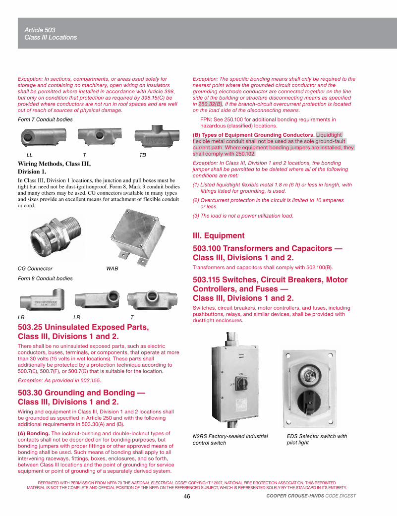
REPRINTED WITH PERMISSION FROM NFPA 70 THE NATIONAL ELECTRICAL CODE® COPYRIGHT © 2007, NATIONAL FIRE PROTECTION ASSOCIATION. THIS REPRINTED
MATERIAL IS NOT THE COMPLETE AND OFFICIAL POSITION OF THE NFPA ON THE REFERENCED SUBJECT, WHICH IS REPRESENTED SOLELY BY THE STANDARD IN ITS ENTIRETY.
46 COOPER CROUSE-HINDS CODE DIGEST
Exception: The specific bonding means shall only be required to the nearest point where the grounded circuit conductor and the grounding electrode conductor are connected together on the line side of the building or structure disconnecting means as specified in 250.32(B), if the branch-circuit overcurrent protection is located on the load side of the disconnecting means.
FPN: See 250.100 for additional bonding requirements in hazardous (classified) locations.
(B) Types of Equipment Grounding Conductors. Liquidtight flexible metal conduit shall not be used as the sole ground-fault current path. Where equipment bonding jumpers are installed, they shall comply with 250.102.
Exception: In Class III, Division 1 and 2 locations, the bonding jumper shall be permitted to be deleted where all of the following conditions are met:
(1) Listed liquidtight flexible metal 1.8 m (6 ft) or less in length, with fittings listed for grounding, is used.
(2) Overcurrent protection in the circuit is limited to 10 amperes or less.
(3) The load is not a power utilization load.
III. Equipment
503.100 Transformers and Capacitors — Class III, Divisions 1 and 2.Transformers and capacitors shall comply with 502.100(B).
503.115 Switches, Circuit Breakers, Motor Controllers, and Fuses — Class III, Divisions 1 and 2.Switches, circuit breakers, motor controllers, and fuses, including pushbuttons, relays, and similar devices, shall be provided with dusttight enclosures.
N2RS Factory-sealed industrial
control switch
EDS Selector switch with pilot light
Exception: In sections, compartments, or areas used solely for storage and containing no machinery, open wiring on insulators shall be permitted where installed in accordance with Article 398, but only on condition that protection as required by 398.15(C) be provided where conductors are not run in roof spaces and are well out of reach of sources of physical damage.
Form 7 Conduit bodies
LL T TB
Wiring Methods, Class III, Division 1.In Class III, Division 1 locations, the junction and pull boxes must be tight but need not be dust-ignitionproof. Form 8, Mark 9 conduit bodies and many others may be used. CG connectors available in many types and sizes provide an excellent means for attachment of flexible conduit or cord.
CG Connector WAB
Form 8 Conduit bodies
LB LR T
503.25 Uninsulated Exposed Parts, Class III, Divisions 1 and 2.There shall be no uninsulated exposed parts, such as electric conductors, buses, terminals, or components, that operate at more than 30 volts (15 volts in wet locations). These parts shall additionally be protected by a protection technique according to 500.7(E), 500.7(F), or 500.7(G) that is suitable for the location.
Exception: As provided in 503.155.
503.30 Grounding and Bonding — Class III, Divisions 1 and 2.Wiring and equipment in Class III, Division 1 and 2 locations shall be grounded as specified in Article 250 and with the following additional requirements in 503.30(A) and (B).
(A) Bonding. The locknut-bushing and double-locknut types of contacts shall not be depended on for bonding purposes, but bonding jumpers with proper fittings or other approved means of bonding shall be used. Such means of bonding shall apply to all intervening raceways, fittings, boxes, enclosures, and so forth, between Class III locations and the point of grounding for service equipment or point of grounding of a separately derived system.
Article 503Class III Locations

REPRINTED WITH PERMISSION FROM NFPA 70 THE NATIONAL ELECTRICAL CODE® COPYRIGHT © 2007, NATIONAL FIRE PROTECTION ASSOCIATION. THIS REPRINTED
MATERIAL IS NOT THE COMPLETE AND OFFICIAL POSITION OF THE NFPA ON THE REFERENCED SUBJECT, WHICH IS REPRESENTED SOLELY BY THE STANDARD IN ITS ENTIRETY.
47COOPER CROUSE-HINDS CODE DIGEST
503.120 Control Transformers and Resistors — Class III, Divisions 1 and 2.Transformers, impedance coils, and resistors used as or in conjunction with control equipment for motors, generators, and appliances shall be provided with dusttight enclosures complying with the temperature limitations in 503.5.
503.125 Motors and Generators — Class III, Divisions 1 and 2.In Class III, Divisions 1 and 2 locations, motors, generators, and other rotating machinery shall be totally enclosed nonventilated, totally enclosed pipe ventilated, or totally enclosed fan cooled.
Exception: In locations where, in the judgment of the authority having jurisdiction, only moderate accumulations of lint or flyings are likely to collect on, in, or in the vicinity of a rotating electrical machine and where such machine is readily accessible for routine cleaning and maintenance, one of the following shall be permitted:
(1) Self-cleaning textile motors of the squirrel-cage type
(2) Standard open-type machines without sliding contacts, centrifugal or other types of switching mechanisms, including motor overload devices
(3) Standard open-type machines having such contacts, switching mechanisms, or resistance devices enclosed within tight housings without ventilating or other openings
503.128 Ventilating Piping — Class III, Divisions 1 and 2.Ventilating pipes for motors, generators, or other rotating electric machinery, or for enclosures for electric equipment, shall be of metal not less than 0.53 mm (0.021 in.) in thickness, or of equally substantial noncombustible material, and shall comply with the following:
(1) Lead directly to a source of clean air outside of buildings
(2) Be screened at the outer ends to prevent the entrance of small animals or birds
(3) Be protected against physical damage and against rusting or other corrosive influences
Ventilating pipes shall be sufficiently tight, including their connections, to prevent the entrance of appreciable quantities of fibers/flyings into the ventilated equipment or enclosure and to prevent the escape of sparks, flame, or burning material that might ignite accumulations of fibers/flyings or combustible material in the vicinity. For metal pipes, lock seams and riveted or welded joints shall be permitted; and tight-fitting slip joints shall be permitted where some flexibility is necessary, as at connections to motors.
503.130 Luminaires — Class III, Divisions 1 and 2.(A) Fixed Lighting. Luminaires for fixed lighting shall provide enclosures for lamps and lampholders that are designed to minimize entrance of fibers/flyings and to prevent the escape of sparks, burning material, or hot metal. Each luminaire shall be clearly marked to show the maximum wattage of the lamps that shall be permitted without exceeding an exposed surface temperature of 165°C (329°F) under normal conditions of use.
(B) Physical Damage. A luminaire that may be exposed to physical damage shall be protected by a suitable guard.
(C) Pendant Luminaires. Pendant luminaires shall be suspended by stems of threaded rigid metal conduit, threaded intermediate metal conduit, threaded metal tubing of equivalent thickness, or by chains with approved fittings. For stems longer than 300 mm (12 in.), permanent and effective bracing against lateral displacement shall be provided at a level not more than 300 mm (12 in.) above the lower end of the stem, or flexibility in the form of an identified fitting or a flexible connector shall be provided not more than 300 mm (12 in.) from the point of attachment to the supporting box or fitting.
(D) Portable Lighting Equipment. Portable lighting equipment shall be equipped with handles and protected with substantial guards. Lampholders shall be of the unswitched type with no provision for receiving attachment plugs. There shall be no exposed current-carrying metal parts, and all exposed non–current-carrying metal parts shall be grounded. In all other respects, portable lighting equipment shall comply with 503.130(A).
This CHAMP® DMV luminaire with guard provides aisle lighting in a storage facility.
Luminaires, Class III.Guards are provided to protect against damage, and enclosures are designed to minimize entrance of fibers and flyings, and to prevent the escape of sparks, burning material, or hot metal. Cooper Crouse-Hinds will supply specific information on operating temperatures of these luminaires, on request. (503.130).
Pendant Fixtures and Supports, Class lll. Suggested Installation Methods
T
UNE
UNH
UNJ
Ball
UNJC
Cushion
Article 503Class III Locations

REPRINTED WITH PERMISSION FROM NFPA 70 THE NATIONAL ELECTRICAL CODE® COPYRIGHT © 2007, NATIONAL FIRE PROTECTION ASSOCIATION. THIS REPRINTED
MATERIAL IS NOT THE COMPLETE AND OFFICIAL POSITION OF THE NFPA ON THE REFERENCED SUBJECT, WHICH IS REPRESENTED SOLELY BY THE STANDARD IN ITS ENTIRETY.
48 COOPER CROUSE-HINDS CODE DIGEST
503.135 Utilization Equipment — Class III, Divisions 1 and 2.(A) Heaters. Electrically heated utilization equipment shall be identified for Class III locations.
(B) Motors. Motors of motor-driven utilization equipment shall comply with 503.125.
(C) Switches, Circuit Breakers, Motor Controllers, and Fuses.
Switches, circuit breakers, motor controllers, and fuses shall comply with 503.115.
503.140 Flexible Cords — Class III, Divisions 1 and 2.Flexible cords shall comply with the following:
(1) Be of a type listed for extra-hard usage
(2) Contain, in addition to the conductors of the circuit, an equipment grounding conductor complying with 400.23
(3) Be connected to terminals or to supply conductors in an approved manner
(4) Be supported by clamps or other suitable means in such a manner that there will be no tension on the terminal connections
(5) Be provided with suitable means to prevent the entrance of fibers/flyings where the cord enters boxes or fittings
503.145 Receptacles and Attachment Plugs — Class III, Divisions 1 and 2.Receptacles and attachment plugs shall be of the grounding type, shall be designed so as to minimize the accumulation or the entry of fibers/flyings, and shall prevent the escape of sparks or molten particles.
Exception: In locations where, in the judgment of the authority having jurisdiction, only moderate accumulations of lint or flyings will be likely to collect in the vicinity of a receptacle, and where such receptacle is readily accessible for routine cleaning, general-purpose grounding-type receptacles mounted so as to minimize the entry of fibers/flyings shall be permitted.
ARE Receptacle with spring door
WSQC ReceptacleW2SR Interlocked Arktite® receptacle
503.150 Signaling, Alarm, Remote-Control, and Local Loudspeaker Intercommunications Systems — Class III, Divisions 1 and 2.Signaling, alarm, remote-control, and local loudspeaker intercommunications systems shall comply with the requirements of Article 503 regarding wiring methods, switches, transformers, resistors, motors, luminaires, and related components.
503.155 Electric Cranes, Hoists, and Similar Equipment — Class III, Divisions 1 and 2.Where installed for operation over combustible fibers or accumulations of flyings, traveling cranes and hoists for material handling, traveling cleaners for textile machinery, and similar equipment shall comply with 503.155(A) through (D).
(A) Power Supply. Power supply to contact conductors shall be electrically isolated from all other systems, ungrounded, and shall be equipped with an acceptable ground detector that gives an alarm and automatically de-energizes the contact conductors in case of a fault to ground or gives a visual and audible alarm as long as power is supplied to the contact conductors and the ground fault remains.
(B) Contact Conductors. Contact conductors shall be located or guarded so as to be inaccessible to other than authorized persons and shall be protected against accidental contact with foreign objects.
(C) Current Collectors. Current collectors shall be arranged or guarded so as to confine normal sparking and prevent escape of sparks or hot particles. To reduce sparking, two or more separate surfaces of contact shall be provided for each contact conductor. Reliable means shall be provided to keep contact conductors and current collectors free of accumulations of lint or flyings.
(D) Control Equipment. Control equipment shall comply with 503.115 and 503.120.
503.160 Storage Battery Charging Equipment — Class III, Divisions 1 and 2.Storage battery charging equipment shall be located in separate rooms built or lined with substantial noncombustible materials. The rooms shall be constructed to prevent the entrance of ignitible amounts of flyings or lint and shall be well ventilated.
Article 503Class III Locations

REPRINTED WITH PERMISSION FROM NFPA 70 THE NATIONAL ELECTRICAL CODE® COPYRIGHT © 2007, NATIONAL FIRE PROTECTION ASSOCIATION. THIS REPRINTED
MATERIAL IS NOT THE COMPLETE AND OFFICIAL POSITION OF THE NFPA ON THE REFERENCED SUBJECT, WHICH IS REPRESENTED SOLELY BY THE STANDARD IN ITS ENTIRETY.
49COOPER CROUSE-HINDS CODE DIGEST
Article 504
504.1 Scope.This article covers the installation of intrinsically safe (I.S.) apparatus, wiring, and systems for Class I, II, and III locations.
FPN: For further information, see ANSI/ISA-RP 12.06.01-2003, Wiring Methods for Hazardous (Classified) Locations Instrumentation — Part 1: Intrinsic Safety.
504.2 Definitions.Associated Apparatus. Apparatus in which the circuits are not necessarily intrinsically safe themselves but that affect the energy in the intrinsically safe circuits and are relied on to maintain intrinsic safety. Associated apparatus may be either of the following:
(1) Electrical apparatus that has an alternative-type protection for use in the appropriate hazardous (classified) location
(2) Electrical apparatus not so protected that shall not be used within a hazardous (classified) location
FPN No. 1: Associated apparatus has identified intrinsically safe connections for intrinsically safe apparatus and also may have connections for nonintrinsically safe apparatus.
FPN No. 2: An example of associated apparatus is an intrinsic safety barrier, which is a network designed to limit the energy (voltage and current) available to the protected circuit in the hazardous (classified) location, under specified fault conditions.
Control Drawing. See definition in 500.2.
Different Intrinsically Safe Circuits. Intrinsically safe circuits in which the possible interconnections have not been evaluated and identified as intrinsically safe.
Intrinsically Safe Apparatus. Apparatus in which all the circuits are intrinsically safe.
Intrinsically Safe Circuit. A circuit in which any spark or thermal effect is incapable of causing ignition of a mixture of flammable or combustible material in air under prescribed test conditions.
FPN: Test conditions are described in ANSI/UL 913-1997, Standard for Safety, Intrinsically Safe Apparatus and Associated Apparatus for Use in Class I, II, and III, Division 1, Hazardous (Classified) Locations.
Intrinsically Safe System. An assembly of interconnected intrinsically safe apparatus, associated apparatus, and interconnecting cables in that those parts of the system that may be used in hazardous (classified) locations are intrinsically safe circuits.
FPN: An intrinsically safe system may include more than one intrinsically safe circuit.
Simple Apparatus. An electrical component or combination of components of simple construction with well-defined electrical parameters that does not generate more than 1.5 volts, 100 milliamps, and 25 milliwatts, or a passive component that does not dissipate more than 1.3 watts and is compatible with the intrinsic safety of the circuit in which it is used.
FPN: The following apparatus are examples of simple apparatus:
(a) Passive components, for example, switches, junction boxes, resistance temperature devices, and simple semiconductor devices such as LEDs
(b) Sources of stored energy consisting of single components in simple circuits with well-defined parameters, for example, capacitors or inductors, whose values are considered when determining the overall safety of the system
(c) Sources of generated energy, for example, thermocouples and photocells, which do not generate more than 1.5 V, 100 mA, and 25 mW
504.3 Application of Other Articles.Except as modified by this article, all applicable articles of this Code shall apply.
504.4 Equipment.All intrinsically safe apparatus and associated apparatus shall be listed.
Exception: Simple apparatus, as described on the control drawing, shall not be required to be listed.
504.10 Equipment Installation.(A) Control Drawing. Intrinsically safe apparatus, associated apparatus, and other equipment shall be installed in accordance with the control drawing(s).
Exception: A simple apparatus that does not interconnect intrinsically safe circuits.
FPN No. 1: The control drawing identification is marked on the apparatus.
FPN No. 2: Associated apparatus with a marked Um of less than 250 V may require additional overvoltage protection at the inputs to limit any possible fault voltages to less than the Um marked on the product.
(B) Location. Intrinsically safe apparatus shall be permitted to be installed in any hazardous (classified) location for which it has been identified. General-purpose enclosures shall be permitted for intrinsically safe apparatus.
Associated apparatus shall be permitted to be installed in any hazardous (classified) location for which it has been identified or, if protected by other means, permitted by Articles 501 through 503 and Article 505.
Simple apparatus shall be permitted to be installed in any hazardous (classified) location in which the maximum surface temperature of the simple apparatus does not exceed the ignition temperature of the flammable gases or vapors, flammable liquids, combustible dusts, or ignitible fibers/flyings present.
For simple apparatus, the maximum surface temperature can be determined from the values of the output power from the associated apparatus or apparatus to which it is connected to obtain the temperature class. The temperature class can be determined by:
(1) Reference to Table 504.10(B)
(2) Calculation using the formula:
T = PoR
th + T
amb
where:
T is the surface temperature
Po is the output power marked on the associated apparatus or
intrinsically safe apparatus
Rth is the thermal resistance of the simple apparatus
Tamb
is the ambient temperature (normally 40°C) and reference Table 500.8(C)
Article 504Intrinsically Safe Systems

REPRINTED WITH PERMISSION FROM NFPA 70 THE NATIONAL ELECTRICAL CODE® COPYRIGHT © 2007, NATIONAL FIRE PROTECTION ASSOCIATION. THIS REPRINTED
MATERIAL IS NOT THE COMPLETE AND OFFICIAL POSITION OF THE NFPA ON THE REFERENCED SUBJECT, WHICH IS REPRESENTED SOLELY BY THE STANDARD IN ITS ENTIRETY.
50 COOPER CROUSE-HINDS CODE DIGEST
Exception No. 4: Intrinsically safe circuits passing through a Division 2 or Zone 2 location to supply apparatus that is located in a Division 1, Zone 0 or Zone 1 location shall be permitted to be installed in a raceway, cable tray, or cable along with nonincendive field wiring circuits when installed in accordance with 504.30(B).
FPN: Nonincendive field wiring circuits are described in 501.10(B)(3), 502.10(B)(3), 503.10(B)(3), 505.15(C)(1)(g), and 506.15(C)(7).
(2) Within Enclosures. Conductors of intrinsically safe circuits shall be separated from conductors of nonintrinsically safe circuits by one of the following means:
(1) Separation by at least 50 mm (2 in.) from conductors of any nonintrinsically safe circuits.
(2) Separation from conductors of nonintrinsically safe circuits by use of a grounded metal partition 0.91 mm (0.0359 in.) or thicker.
(3) Separation from conductors of nonintrinsically safe circuits by use of an approved insulating partition.
(4) Where either (1) all of the intrinsically safe circuit conductors or (2) all of the nonintrinsically safe circuit conductors are in grounded metal-sheathed or metal-clad cables where the sheathing or cladding is capable of carrying fault current to ground.
FPN: Cables meeting the requirements of Articles 330 and 332 are typical of those considered acceptable.
(5) All conductors shall be secured so that any conductor that might come loose from a terminal cannot come in contact with another terminal.
FPN No. 1: The use of separate wiring compartments for the intrinsically safe and nonintrinsically safe terminals is a typical method of complying with this requirement.
FPN No. 2: Physical barriers such as grounded metal partitions or approved insulating partitions or approved restricted access wiring ducts separated from other such ducts by at least 19 mm (¾ in.) can be used to help ensure the required separation of the wiring.
(3) Other (Not in Raceway or Cable Tray Systems). Conductors and cables of intrinsically safe circuits run in other than raceway or cable tray systems shall be separated by at least 50 mm (2 in.) and secured from conductors and cables of any nonintrinsically safe circuits.
Exception: Where either (1) all of the intrinsically safe circuit conductors are in Type MI or MC cables or (2) all of the nonintrinsically safe circuit conductors are in raceways or Type MI or MC cables where the sheathing or cladding is capable of carrying fault current to ground.
(B) From Different Intrinsically Safe Circuit Conductors. Different intrinsically safe circuits shall be in separate cables or shall be separated from each other by one of the following means:
(1) The conductors of each circuit are within a grounded metal shield.
(2) The conductors of each circuit have insulation with a minimum thickness of 0.25 mm (0.01 in.).
Exception: Unless otherwise identified.
(3) The clearance between two terminals for connection of field wiring of different intrinsically safe circuits shall be at least 6 mm (0.25 in.) unless this clearance is permitted to be reduced by the control drawing.
In addition, components with a surface area smaller than 10 cm2 (excluding lead wires) may be classified as T5 if their surface temperature does not exceed 150°C.
Table 504.10(B) Assessment for T4 Classification According to
Component Size and Temperature
Total Surface Area Excluding
Lead Wires
Requirement for T4 Classification
(Based on 40°C Ambient
Temperature)
<20 mm2
20 mm2 10 cm2
20 mm2
Surface temperature 275°C
Surface temperature 200°C
Power not exceeding 1.3 W*
*Reduce to 1.2 W with an ambient of 60°C or 1.0 W with 80°C ambient
temperature.
FPN: The following apparatus are examples of simple apparatus:
(1) Passive components, for example, switches, junction boxes, resistance temperature devices, and simple semiconductor devices such as LEDs
(2) Sources of generated energy, for example, thermocouples and photocells, which do not generate more than 1.5 V, 100 mA, and 25 mW
Note: When installed in a hazardous area, intrinsically safe barriers
must be mounted in an appropriate explosionproof enclosure. EJB
and GUB enclosures will fulfill this need. Similarly, corrosive
environments will need enclosures made from materials such as our
Krydon® material enclosures.
504.20 Wiring Methods.Any of the wiring methods suitable for unclassified locations, including those covered by Chapter 7 and Chapter 8, shall be permitted for installing intrinsically safe apparatus. Sealing shall be as provided in 504.70, and separation shall be as provided in 504.30.
504.30 Separation of Intrinsically Safe Conductors.(A) From Nonintrinsically Safe Circuit Conductors.
(1) In Raceways, Cable Trays, and Cables. Conductors of intrinsically safe circuits shall not be placed in any raceway, cable tray, or cable with conductors of any nonintrinsically safe circuit.
Exception No. 1: Where conductors of intrinsically safe circuits are separated from conductors of nonintrinsically safe circuits by a distance of at least 50 mm (2 in.) and secured, or by a grounded metal partition or an approved insulating partition.
FPN: No. 20 gauge sheet metal partitions 0.91 mm (0.0359 in.) or thicker are generally considered acceptable.
Exception No. 2: Where either (1) all of the intrinsically safe circuit conductors or (2) all of the nonintrinsically safe circuit conductors are in grounded metal-sheathed or metal-clad cables where the sheathing or cladding is capable of carrying fault current to ground.
FPN: Cables meeting the requirements of Articles 330 and 332 are typical of those considered acceptable.
Exception No. 3: Intrinsically safe circuits in a Division 2 or Zone 2 location shall be permitted to be installed in a raceway, cable tray, or cable along with nonincendive field wiring circuits when installed in accordance with 504.30(B).
Article 504Intrinsically Safe Systems

REPRINTED WITH PERMISSION FROM NFPA 70 THE NATIONAL ELECTRICAL CODE® COPYRIGHT © 2007, NATIONAL FIRE PROTECTION ASSOCIATION. THIS REPRINTED
MATERIAL IS NOT THE COMPLETE AND OFFICIAL POSITION OF THE NFPA ON THE REFERENCED SUBJECT, WHICH IS REPRESENTED SOLELY BY THE STANDARD IN ITS ENTIRETY.
51COOPER CROUSE-HINDS CODE DIGEST
504.50 Grounding(A) Intrinsically Safe Apparatus, Enclosures, and Raceways. Intrinsically safe apparatus, enclosures, and raceways, if of metal, shall be connected to the equipment grounding conductor.
FPN: In addition to an equipment grounding conductor connection, a connection to a grounding electrode may be needed for some associated apparatus, for example, zener diode barriers, if specified in the control drawing. See ANSI/ISA-RP 12.06.01-2003, Wiring Methods for Hazardous (Classified) Locations Instrumentation — Part 1: Intrinsic Safety.
(B) Associated Apparatus and Cable Shields. Associated appa-ratus and cable shields shall be grounded in accordance with the required control drawing. See 504.10(A).
FPN: Supplementary connection(s) to the grounding electrode may be needed for some associated apparatus, for example, zener diode barriers, if specified in the control drawing. See ANSI/ISA RP 12.06.01-2003, Wiring Methods for Hazardous (Classified) Locations Instrumentation — Part 1: Intrinsic Safety.
(C) Connection to Grounding Electrodes. Where connection to a grounding electrode is required, the grounding electrode shall be as specified in 250.52(A)(1), (A)(2), (A)(3), and (A)(4) and shall comply with 250.30(A)(7). Sections 250.52(A)(5), (A)(7) and (A)(8) shall not be used if any of the electrodes specified in 250.52(A)(1), (A)(2), (A)(3), or (A)(4) are present.
504.60 Bonding.(A) Hazardous Locations. In hazardous (classified) locations, intrinsically safe apparatus shall be bonded in the hazardous (classified) location in accordance with 250.100.
(B) Unclassified. In unclassified locations, where metal raceways are used for intrinsically safe system wiring in hazardous (classified) locations, associated apparatus shall be bonded in accordance with 501.30(A), 502.30(A), 503.30(A), 505.25, or 506.25 as applicable.
504.70 Sealing.Conduits and cables that are required to be sealed by 501.15, 502.15, 505.16, and 506.16 shall be sealed to minimize the passage of gases, vapors, or dusts. Such seals shall not be required to be explosionproof or flameproof but shall be identified for the purpose of minimizing passage of gases, vapors, or dusts under normal operating conditions and shall be accessible.
Exception: Seals shall not be required for enclosures that contain only intrinsically safe apparatus, except as required by 501.15(F)(3).
504.80 Identification.Labels required by this section shall be suitable for the environment where they are installed with consideration given to exposure to chemicals and sunlight.
(A) Terminals. Intrinsically safe circuits shall be identified at terminal and junction locations in a manner that will prevent unintentional interference with the circuits during testing and servicing.
(B) Wiring. Raceways, cable trays, and other wiring methods for intrinsically safe system wiring shall be identified with permanently affixed labels with the wording “Intrinsic Safety Wiring” or
equivalent. The labels shall be located so as to be visible after installation and placed so that they may be readily traced through the entire length of the installation. Intrinsic safety circuit labels shall appear in every section of the wiring system that is separated by enclosures, walls, partitions, or floors. Spacing between labels shall not be more than 7.5 m (25 ft).
Exception: Circuits run underground shall be permitted to be identified where they become accessible after emergence from the ground.
FPN No. 1: Wiring methods permitted in unclassified locations may be used for intrinsically safe systems in hazardous (classified) locations. Without labels to identify the application of the wiring, enforcement authorities cannot determine that an installation is in compliance with this Code.
FPN No. 2: In unclassified locations, identification is necessary to ensure that nonintrinsically safe wire will not be inadvertently added to existing raceways at a later date.
(C) Color Coding. Color coding shall be permitted to identify intrinsically safe conductors where they are colored light blue and where no other conductors colored light blue are used. Likewise, color coding shall be permitted to identify raceways, cable trays, and junction boxes where they are colored light blue and contain only intrinsically safe wiring.
Article 505FPN: Rules that are followed by a reference in brackets contain text that has been extracted from NFPA 497-2004, Recommended Practice for the Classification of Flammable Liquids, Gases, or Vapors and of Hazardous (Classified) Locations for Electrical Installations in Chemical Process Areas. Only editorial changes were made to the extracted text to make it consistent with this Code.
505.1 Scope.This article covers the requirements for the zone classification system as an alternative to the division classification system covered in Article 500 for electrical and electronic equipment and wiring for all voltages in Class I, Zone 0, Zone 1, and Zone 2 hazardous (classified) locations where fire or explosion hazards may exist due to flammable gases, vapors, or liquids.
FPN: For the requirements for electrical and electronic equipment and wiring for all voltages in Class I, Division 1 or Division 2; Class II, Division 1 or Division 2; and Class III, Division 1 or Division 2 hazardous (classified) locations where fire or explosion hazards may exist due to flammable gases or vapors, flammable liquids, or combustible dusts or fibers, refer to Articles 500 through 504.
505.2 Definitions.For purposes of this article, the following definitions apply.
Combustible Gas Detection System. A protection technique utilizing stationary gas detectors in industrial establishments.
Electrical and Electronic Equipment. Materials, fittings, devices, appliances, and the like that are part of, or in connection with, an electrical installation.
Article 504Intrinsically Safe Systems
Article 505Class I, Zone 0, 1, and 2 Locations

REPRINTED WITH PERMISSION FROM NFPA 70 THE NATIONAL ELECTRICAL CODE® COPYRIGHT © 2007, NATIONAL FIRE PROTECTION ASSOCIATION. THIS REPRINTED
MATERIAL IS NOT THE COMPLETE AND OFFICIAL POSITION OF THE NFPA ON THE REFERENCED SUBJECT, WHICH IS REPRESENTED SOLELY BY THE STANDARD IN ITS ENTIRETY.
52 COOPER CROUSE-HINDS CODE DIGEST
FPN: Portable or transportable equipment having self-contained power supplies, such as battery-operated equipment, could potentially become an ignition source in hazardous (classified) locations.
Encapsulation “m.” Type of protection where electrical parts that could ignite an explosive atmosphere by either sparking or heating are enclosed in a compound in such a way that this explosive atmosphere cannot be ignited.
FPN No. 1: See ANSI/ISA-60079-18 (12.23.01)-2005, Electrical Apparatus for Use in Class I, Zone 1 Hazardous (Classified) Locations, Type of Protection — Encapsulation “m”; IEC 60079–18-1992, Electrical Apparatus for Explosive Gas Atmospheres — Part 18: Encapsulation “m”; and ANSI/UL 60079-18, Electrical Apparatus for Explosive Gas Atmospheres — Part 18: Encapsulation “m”.
FPN No. 2: Encapsulation is designated type of protection “ma” for use in Zone 0 locations. Encapsulation is designated type of protection “m” or “mb” for use in Zone 1 locations.
Flameproof “d.” Type of protection where the enclosure will withstand an internal explosion of a flammable mixture that has penetrated into the interior, without suffering damage and without causing ignition, through any joints or structural openings in the enclosure, of an external explosive gas atmosphere consisting of one or more of the gases or vapors for which it is designed.
FPN: See ANSI/ISA-60079-1 (12.22.01)-2005, Electrical Apparatus for Use in Class I, Zone 1 and 2 Hazardous (Classified) Locations, Type of Protection — Flameproof “d”; and ANSI/UL 60079–1, Electrical Apparatus for Explosive Gas Atmospheres — Part 1: Flameproof Enclosures “d.”
Increased Safety “e.” Type of protection applied to electrical equipment that does not produce arcs or sparks in normal service and under specified abnormal conditions, in which additional measures are applied so as to give increased security against the possibility of excessive temperatures and of the occurrence of arcs and sparks.
FPN: See ANSI/ISA-60079-7 (12.16.01)-2002, Electrical Apparatus for Use in Class I, Zone 1 Hazardous (Classified) Locations, Type of Protection — Increased Safety “e”; and ANSI/UL 60079-7, Electrical Apparatus for Explosive Gas Atmospheres — Part 7: Increased Safety “e.”
Intrinsic Safety “i.” Type of protection where any spark or thermal effect is incapable of causing ignition of a mixture of flammable or combustible material in air under prescribed test conditions.
FPN No. 1: See ANSI/UL 913-1997, Intrinsically Safe Apparatus and Associated Apparatus for Use in Class I, II, and III, Hazardous Locations; ANSI/ISA-60079-11 (12.02.01)-2002, Electrical Apparatus for Use in Class I, Zones 0, 1 and 2 Hazardous (Classified) Locations — Intrinsic Safety “i”; and ANSI/UL 60079-11, Electrical Apparatus for Explosive Gas Atmospheres — Part II: Intrinsic Safety “i.”
FPN No. 2: Intrinsic safety is designated type of protection “ia” for use in Zone 0 locations. Intrinsic safety is designated type of protection “ib” for use in Zone 1 locations.
FPN No. 3: Intrinsically safe associated apparatus, designated by [ia] or [ib], is connected to intrinsically safe apparatus (“ia” or “ib,” respectively) but is located outside the hazardous (classified) location unless also protected by another type of protection (such as flameproof).
Oil Immersion “o.” Type of protection where electrical equipment is immersed in a protective liquid in such a way that an explosive atmosphere that may be above the liquid or outside the enclosure cannot be ignited.
FPN: See ANSI/ISA-60079-6 (12.26.01)-1998, Electrical Apparatus for Use in Class I, Zone 1 Hazardous (Classified) Locations, Type of Protection — Oil-Immersion “o”; and ANSI/UL 60079-6, Electrical Apparatus for Explosive Gas Atmospheres — Part 6: Oil-Immersion “o.”
Powder Filling “q.” Type of protection where electrical parts capable of igniting an explosive atmosphere are fixed in position and completely surrounded by filling material (glass or quartz powder) to prevent the ignition of an external explosive atmosphere.
FPN: See ANSI/ISA-60079-5 (12.25.01)-1998, Electrical Apparatus for Use in Class I, Zone 1 Hazardous (Classified) Locations Type of Protection — Powder Filling “q”; and ANSI/UL 60079-5, Electrical Apparatus for Explosive Gas Atmospheres — Part 5: Powder Filling “q.”
Pressurization “p.” Type of protection for electrical equipment that uses the technique of guarding against the ingress of the external atmosphere, which may be explosive, into an enclosure by maintaining a protective gas therein at a pressure above that of the external atmosphere.
FPN: See ANSI/ISA-60079-2 (12.04.01)-2004, Electrical Apparatus for Explosive Gas Atmospheres — Part 2: Pressurized Enclosures “p”; and IEC 60079-13-1982, Electrical Apparatus for Explosive Gas Atmospheres — Part 13: Construction and Use of Rooms or Buildings Protected by Pressurization.
Type of Protection “n.” Type of protection where electrical equipment, in normal operation, is not capable of igniting a surrounding explosive gas atmosphere and a fault capable of causing ignition is not likely to occur.
FPN: See ANSI/UL 60079-15-2002, Electrical Apparatus for Explosive Gas Atmospheres — Part 15: Type of Protection “n”; and ANSI/ISA-60079-15 (12.12.02)-2003, Electrical Apparatus for Use in Class I, Zone 2 Hazardous (Classified) Locations: Type of Protection “n.”
Unclassified Locations. Locations determined to be neither Class I, Division 1; Class I, Division 2; Class I, Zone 0; Class I, Zone 1; Class I, Zone 2; Class II, Division 1; Class II, Division 2; Class III, Division 1; Class III, Division 2; or any combination thereof.
505.3 Other Articles.
All other applicable rules contained in this Code shall apply to electrical equipment and wiring installed in hazardous (classified) locations.
Exception: As modified by Article 504 and this article.
505.4 General.(A) Documentation for Industrial Occupancies. All areas in industrial occupancies designated as hazardous (classified) locations shall be properly documented. This documentation shall be available to those authorized to design, install, inspect, maintain, or operate electrical equipment at the location.
FPN: For examples of area classification drawings, see ANSI/API RP 505-1997, Recommended Practice for Classification of Locations for Electrical Installations at Petroleum Facilities Classified as Class I, Zone 0, Zone 1, or Zone 2; ANSI/ISA-TR
Article 505Class I, Zone 0, 1, and 2 Locations

REPRINTED WITH PERMISSION FROM NFPA 70 THE NATIONAL ELECTRICAL CODE® COPYRIGHT © 2007, NATIONAL FIRE PROTECTION ASSOCIATION. THIS REPRINTED
MATERIAL IS NOT THE COMPLETE AND OFFICIAL POSITION OF THE NFPA ON THE REFERENCED SUBJECT, WHICH IS REPRESENTED SOLELY BY THE STANDARD IN ITS ENTIRETY.
53COOPER CROUSE-HINDS CODE DIGEST
(12.24.01)-1998 (IEC 60079-10 Mod), Recommended Practice for Classification of Locations for Electrical Installations Classified as Class I, Zone 0, Zone 1, or Zone 2; IEC 60079-10-1995, Electrical Apparatus for Explosive Gas Atmospheres, Classification of Hazardous Areas; and Model Code of Safe Practice in the Petroleum Industry, Part 15: Area Classification Code for Petroleum Installations, IP 15, The Institute of Petroleum, London.
(B) Reference Standards. Important information relating to topics covered in Chapter 5 may be found in other publications.
FPN No. 1: It is important that the authority having jurisdiction be familiar with recorded industrial experience as well as with standards of the National Fire Protection Association (NFPA), the American Petroleum Institute (API), the Instrumentation, Systems, and Automation Society (ISA), and the International Electrotechnical Commission (IEC) that may be of use in the classification of various locations, the determination of adequate ventilation, and the protection against static electricity and lightning hazards.
FPN No. 2: For further information on the classification of locations, see ANSI/API RP 505-1997, Recommended Practice for Classification of Locations for Electrical Installations at Petroleum Facilities Classified as Class I, Zone 0, Zone 1, or Zone 2; ANSI/ISA-TR (12.24.01)-1998 (IEC 60079-10 Mod), Recommended Practice for Classification of Locations for Electrical Installations Classified as Class I, Zone 0, Zone 1, or Zone 2; IEC 60079-10-1995, Electrical Apparatus for Explosive Gas Atmospheres, Classification of Hazardous Areas; and Model Code of Safe Practice in the Petroleum Industry, Part 15: Area Classification Code for Petroleum Installations, IP 15, The Institute of Petroleum, London.
FPN No. 3: For further information on protection against static electricity and lightning hazards in hazardous (classified) locations, see NFPA 77-2007, Recommended Practice on Static Electricity; NFPA 780-2004, Standard for the Installation of Lightning Protection Systems; and API RP 2003-1998, Protection Against Ignitions Arising Out of Static Lightning and Stray Currents.
FPN No. 4: For further information on ventilation, see NFPA 30-2007, Flammable and Combustible Liquids Code, and ANSI/API RP 505-1997, Recommended Practice for Classification of Locations for Electrical Installations at Petroleum Facilities Classified as Class I, Zone 0, Zone 1, or Zone 2.
FPN No. 5: For further information on electrical systems for hazardous (classified) locations on offshore oil and gas producing platforms, see ANSI/API RP 14FZ-2000, Recommended Practice for Design and Installation of Electrical Systems for Fixed and Floating Offshore Petroleum Facilities for Unclassified and Class I, Zone 0, Zone 1, and Zone 2 Locations.
FPN No. 6: For further information on the installation of electrical equipment in hazardous (classified) locations in general, see IEC 60079-14-1996, Electrical Apparatus for Explosive Gas Atmospheres — Part 14: Electrical Installations in Explosive Gas Atmospheres (Other Than Mines), and IEC 60079-16-1990, Electrical Apparatus for Explosive Gas Atmospheres — Part 16: Artificial Ventilation for the Protection of Analyzer(s) Houses.
FPN No. 7: For further information on application of electrical equipment in hazardous (classified) locations in general, see ANSI/ISA-60079-0 (12.00.01)-2005, Electrical Apparatus for Use
in Class I, Zones 0 and 1, Hazardous (Classified) Locations: General Requirements; ANSI/ISA-12.01.01-1999, Definitions and Information Pertaining to Electrical Apparatus in Hazardous (Classified) Locations; and ANSI/UL 60079-0, Electrical Apparatus for Explosive Gas Atmospheres — Part 0: General Requirements.
505.5 Classifications of Locations.(A) Classification of Locations. Locations shall be classified depending on the properties of the flammable vapors, liquids, or gases that may be present and the likelihood that a flammable or combustible concentration or quantity is present. Where pyrophoric materials are the only materials used or handled, these locations shall not be classified. Each room, section, or area shall be considered individually in determining its classification.
FPN No. 1: See 505.7 for restrictions on area classification.
FPN No. 2: Through the exercise of ingenuity in the layout of electrical installations for hazardous (classified) locations, it is frequently possible to locate much of the equipment in reduced level of classification or in an unclassified location and, thus, to reduce the amount of special equipment required.
Rooms and areas containing ammonia refrigeration systems that are equipped with adequate mechanical ventilation may be classified as “unclassified” locations.
FPN: For further information regarding classification and ventilation of areas involving ammonia, see ANSI/ASHRAE 15-1994, Safety Code for Mechanical Refrigeration; and ANSI/CGA G2.1-1989 (14-39), Safety Requirements for the Storage and Handling of Anhydrous Ammonia.
(B) Class I, Zone 0, 1, and 2 Locations. Class I, Zone 0, 1, and 2 locations are those in which flammable gases or vapors are or may be present in the air in quantities sufficient to produce explosive or ignitible mixtures. Class I, Zone 0, 1, and 2 locations shall include those specified in 505(B)(1), (B)(2), and (B)(3).
(1) Class I, Zone 0. A Class I, Zone 0 location is a location in which
(1) Ignitible concentrations of flammable gases or vapors are present continuously, or
(2) Ignitible concentrations of flammable gases or vapors are present for long periods of time.
FPN No. 1: As a guide in determining when flammable gases or vapors are present continuously or for long periods of time, refer to ANSI/API RP 505-1997, Recommended Practice for Classification of Locations for Electrical Installations of Petroleum Facilities Classified as Class I, Zone 0, Zone 1 or Zone 2; ANSI/ISA-TR 12.24.01-1998 (IEC 60079-10 Mod), Recommended Practice for Classification of Locations for Electrical Installations Classified as Class I, Zone 0, Zone 1, or Zone 2; IEC 60079-10-1995, Electrical Apparatus for Explosive Gas Atmospheres, Classifications of Hazardous Areas; and Area Classification Code for Petroleum Installations, Model Code, Part 15, Institute of Petroleum.
FPN No. 2: This classification includes locations inside vented tanks or vessels that contain volatile flammable liquids; inside inadequately vented spraying or coating enclosures, where volatile flammable solvents are used; between the inner and outer roof sections of a floating roof tank containing volatile flammable liquids; inside open vessels, tanks and pits containing volatile flammable liquids; the interior of an exhaust duct that is
Article 505Class I, Zone 0, 1, and 2 Locations

REPRINTED WITH PERMISSION FROM NFPA 70 THE NATIONAL ELECTRICAL CODE® COPYRIGHT © 2007, NATIONAL FIRE PROTECTION ASSOCIATION. THIS REPRINTED
MATERIAL IS NOT THE COMPLETE AND OFFICIAL POSITION OF THE NFPA ON THE REFERENCED SUBJECT, WHICH IS REPRESENTED SOLELY BY THE STANDARD IN ITS ENTIRETY.
54 COOPER CROUSE-HINDS CODE DIGEST
flammable vapors are handled, processed, or used but in which the liquids, gases, or vapors normally are confined within closed containers of closed systems from which they can escape, only as a result of accidental rupture or breakdown of the containers or system, or as a result of the abnormal operation of the equipment with which the liquids or gases are handled, processed, or used; or
(3) In which ignitible concentrations of flammable gases or vapors normally are prevented by positive mechanical ventilation but which may become hazardous as a result of failure or abnormal operation of the ventilation equipment; or
(4) That is adjacent to a Class I, Zone 1 location, from which ignitible concentrations of flammable gases or vapors could be communicated, unless such communication is prevented by adequate positive-pressure ventilation from a source of clean air and effective safeguards against ventilation failure are provided.
FPN: The Zone 2 classification usually includes locations where volatile flammable liquids or flammable gases or vapors are used but which would become hazardous only in case of an accident or of some unusual operating condition.
This alternate Zone Classification is based on the IEC three-zone
system; the Table below briefly illustrates the relationship between
Zones and Divisions. The above definitions of Zones 1 and 2, however,
are significantly different from the IEC definitions and it was not
immediately clear that the two systems could be harmonized.
Area Classification
Class Zone Description Typical Example
Class I Liquids, Vapors & Gases
Zone 0 Similar to Division 1, continuously hazardous
vapor space in a vented tank
Zone 1 Similar to Division 1, frequently hazardous under normal condi-tions
container filling area in a refinery
Zone 2 Similar to Division 2, hazardous under abnormal conditions
container storage area
Since the introduction of the Zone classification system into the 1996 NEC, however, three national documents now contain guidelines for its application:
Recommended Practice for Classification of Locations for Electrical Installations Classified as Class I, Zone 0, Zone 1, or Zone 2. This document has been allowed to expire because it was of questionable usefulness since the two other American National Standards would preempt it.
Recommended Practice for the Classification of Flammable Liquids, Gases, or Vapors and of Hazardous (Classified) Locations for Electrical Installations in Chemical Process Areas
Recommended Practice for Classification of Locations for Electrical Installations at Petroleum Facilities Classified as Class I, Zone 0, Zone 1 and Zone 2
NFPA 497 includes Zone classifications as an alternative to Divisions
for areas and processes typical to the chemical industry. API RP505 is
a companion to RP500 for Divisions and contains recommended Zone
classifications related to the petroleum industry. The NFPA and API
used to vent ignitible concentrations of gases or vapors; and inside inadequately ventilated enclosures that contain normally venting instruments utilizing or analyzing flammable fluids and venting to the inside of the enclosures.
FPN No. 3: It is not good practice to install electrical equipment in Zone 0 locations except when the equipment is essential to the process or when other locations are not feasible. [See 505.5(A) FPN No. 2.] If it is necessary to install electrical systems in a Zone 0 location, it is good practice to install intrinsically safe systems as described by Article 504.
(2) Class I, Zone 1. A Class I, Zone 1 location is a location
(1) In which ignitible concentrations of flammable gases or vapors are likely to exist under normal operating conditions; or
(2) In which ignitible concentrations of flammable gases or vapors may exist frequently because of repair or maintenance operations or because of leakage; or
(3) In which equipment is operated or processes are carried on, of such a nature that equipment breakdown or faulty operations could result in the release of ignitible concentrations of flammable gases or vapors and also cause simultaneous failure of electrical equipment in a mode to cause the electrical equipment to become a source of ignition; or
(4) That is adjacent to a Class I, Zone 0 location from which ignitible concentrations of vapors could be communicated, unless communication is prevented by adequate positive pressure ventilation from a source of clean air and effective safeguards against ventilation failure are provided.
FPN No. 1: Normal operation is considered the situation when plant equipment is operating within its design parameters. Minor releases of flammable material may be part of normal operations. Minor releases include the releases from mechanical packings on pumps. Failures that involve repair or shutdown (such as the breakdown of pump seals and flange gaskets, and spillage caused by accidents) are not considered normal operation.
FPN No. 2: This classification usually includes locations where volatile flammable liquids or liquefied flammable gases are transferred from one container to another. In areas in the vicinity of spraying and painting operations where flammable solvents are used; adequately ventilated drying rooms or compartments for evaporation of flammable solvents; adequately ventilated locations containing fat and oil extraction equipment using volatile flammable solvents; portions of cleaning and dyeing plants where volatile flammable liquids are used; adequately ventilated gas generator rooms and other portions of gas manufacturing plants where flammable gas may escape; inadequately ventilated pump rooms for flammable gas or for volatile flammable liquids; the interiors of refrigerators and freezers in which volatile flammable materials are stored in the open, lightly stoppered, or in easily ruptured containers; and other locations where ignitible concentrations of flammable vapors or gases are likely to occur in the course of normal operation but not classified Zone 0.
(3) Class I, Zone 2. A Class I, Zone 2 location is a location
(1) In which ignitible concentrations of flammable gases or vapors are not likely to occur in normal operation and, if they do occur, will exist only for a short period; or
(2) In which volatile flammable liquids, flammable gases, or
Article 505Class I, Zone 0, 1, and 2 Locations

REPRINTED WITH PERMISSION FROM NFPA 70 THE NATIONAL ELECTRICAL CODE® COPYRIGHT © 2007, NATIONAL FIRE PROTECTION ASSOCIATION. THIS REPRINTED
MATERIAL IS NOT THE COMPLETE AND OFFICIAL POSITION OF THE NFPA ON THE REFERENCED SUBJECT, WHICH IS REPRESENTED SOLELY BY THE STANDARD IN ITS ENTIRETY.
55COOPER CROUSE-HINDS CODE DIGEST
FPN: Group IIC is equivalent to a combination of Class I, Group A, and Class I, Group B, as described in 500.6(A)(1) and 500.6(A)(2).
(B) Group IIB. Atmospheres containing acetaldehyde, ethylene, or flammable gas, flammable liquid–produced vapor, or combustible liquid–produced vapor mixed with air that may burn or explode, having either maximum experimental safe gap (MESG) values greater than 0.50 mm and less than or equal to 0.90 mm or minimum igniting current ratio (MIC ratio) greater than 0.45 and less than or equal to 0.80. [497:3.3.5.2.2]
FPN: Group IIB is equivalent to Class I, Group C, as described in 500.6(A)(3).
(C) Group IIA. Atmospheres containing acetone, ammonia, ethyl alcohol, gasoline, methane, propane, or flammable gas, flammable liquid–produced vapor, or combustible liquid–produced vapor mixed with air that may burn or explode, having either a maximum experiment safe gap (MESG) value greater than 0.90 mm or minimum igniting current ratio (MIC ratio) greater than 0.80. [497:3.3.5.2.3]
FPN: Group IIA is equivalent to Class I, Group D as described in 500.6(A)(4).
The grouping of flammable materials in the Zone system is considerably different than in the Divisions’ Groups A, B, C, and D. Zone Group I relates to mines and is not covered by the NEC. Zone Group II applies to other than mines and is subdivided into Groups IIA, IIB, and IIC. As explained in Fine Print Notes, Group IIA is equivalent to the Division Group D, IIB is equivalent to C, and IIC is equivalent to a combination of A and B. Because flameproof (similar to explosionproof) equipment rated for hydrogen (Group B) has become widely available, but little is rated for acetylene (Group A), it is common to find enclosures marked IIB + Hydrogen or IIB + H2. This marking is permitted, but not explicitly, by the rules in 505.9(C). See the FPN under 505.9(B)(2).
505.7 Special Precaution.Article 505 requires equipment construction and installation that ensures safe performance under conditions of proper use and maintenance.
FPN No. 1: It is important that inspection authorities and users exercise more than ordinary care with regard to the installation and maintenance of electrical equipment in hazardous (classified) locations.
FPN No. 2: Low ambient conditions require special consideration. Electrical equipment depending on the protection techniques described by 505.8(A) may not be suitable for use at temperatures lower than -20°C (-4°F) unless they are identified for use at lower temperatures. However, at low ambient temperatures, flammable concentrations of vapors may not exist in a location classified Class I, Zones 0, 1, or 2 at normal ambient temperature.
(A) Implementation of Zone Classification System. Classification of areas, engineering and design, selection of equipment and wiring methods, installation, and inspection shall be performed by qualified persons.
(B) Dual Classification. In instances of areas within the same facility classified separately, Class I, Zone 2 locations shall be permitted to abut, but not overlap, Class I, Division 2 locations. Class I, Zone 0 or Zone 1 locations shall not abut Class I, Division 1 or Division 2 locations.
documents contain numerous diagrams with specific dimensions of
classified areas and it should be noted that, for a given process or piece
of equipment, the recommended extent of Zone 1 areas is the same as
for Division 1, and similarly for Zone 2 and Division 2. In the end, the
only essential difference between the two systems is that a few of the
Zone diagrams contain a small Zone 0.
It has been estimated that less than one percent of classified areas would
qualify as Zone 0. It is also generally accepted that Division 1
constitutes 10 percent or less of classified areas in the U.S. In countries
using the IEC classification system, however, Zone 1 commonly
represents up to 60 percent of classified areas. The disparity between
these two ratios is another indication that Zone 0 is not the only
difference between the Division and the IEC Zone system.
505.6 Material Groups.For purposes of testing, approval, and area classification, various air mixtures (not oxygen enriched) shall be grouped as required in 505.6(A), (B), and (C).
FPN: Group I is intended for use in describing atmospheres that contain firedamp (a mixture of gases, composed mostly of methane, found underground, usually in mines). This Code does not apply to installations underground in mines. See 90.2(B).
Group II shall be subdivided into IIC, IIB, and IIA, as noted in 505.6(A), (B), and (C), according to the nature of the gas or vapor, for protection techniques “d,” “ia,” “ib,” “[ia],” and “[ib],” and, where applicable, “n” and “o.”
FPN No. 1: The gas and vapor subdivision as described above is based on the maximum experimental safe gap (MESG), minimum igniting current (MIC), or both. Test equipment for determining the MESG is described in IEC 60079-1A-1975, Amendment No. 1 (1993), Construction and Verification Tests of Flameproof Enclosures of Electrical Apparatus; and UL Technical Report No. 58 (1993). The test equipment for determining MIC is described in IEC 60079-11-1999, Electrical Apparatus for Explosive Gas Atmospheres — Part 11: Intrinsic Safety “i.” The classification of gases or vapors according to their maximum experimental safe gaps and minimum igniting currents is described in IEC 60079-12-1978, Classification of Mixtures of Gases or Vapours with Air According to Their Maximum Experimental Safe Gaps and Minimum Igniting Currents.
FPN No. 2: Verification of electrical equipment utilizing protection techniques “e,” “m,” “p,” and “q,” due to design technique, does not require tests involving MESG or MIC. Therefore, Group II is not required to be subdivided for these protection techniques.
FPN No. 3: It is necessary that the meanings of the different equipment markings and Group II classifications be carefully observed to avoid confusion with Class I, Divisions 1 and 2, Groups A, B, C, and D.
Class I, Zone 0, 1, and 2, groups shall be as follows:
(A) Group IIC. Atmospheres containing acetylene, hydrogen, or flammable gas, flammable liquid–produced vapor, or combustible liquid–produced vapor mixed with air that may burn or explode, having either a maximum experimental safe gap (MESG) value less than or equal to 0.50 mm or minimum igniting current ratio (MIC ratio) less than or equal to 0.45. [497:3.3.5.2.1]
Article 505Class I, Zone 0, 1, and 2 Locations

REPRINTED WITH PERMISSION FROM NFPA 70 THE NATIONAL ELECTRICAL CODE® COPYRIGHT © 2007, NATIONAL FIRE PROTECTION ASSOCIATION. THIS REPRINTED
MATERIAL IS NOT THE COMPLETE AND OFFICIAL POSITION OF THE NFPA ON THE REFERENCED SUBJECT, WHICH IS REPRESENTED SOLELY BY THE STANDARD IN ITS ENTIRETY.
56 COOPER CROUSE-HINDS CODE DIGEST
(C) Reclassification Permitted. A Class I, Division 1 or Division 2 location shall be permitted to be reclassified as a Class I, Zone 0, Zone 1, or Zone 2 location, provided all of the space that is classified because of a single flammable gas or vapor source is reclassified under the requirements of this article.
(D) Solid Obstacles. Flameproof equipment with flanged joints shall not be installed such that the flange openings are closer than the distances shown in Table 505.7(D) to any solid obstacle that is not a part of the equipment (such as steelworks, walls, weather guards, mounting brackets, pipes, or other electrical equipment) unless the equipment is listed for a smaller distance of separation.
Table 505.7(D) Minimum Distance of Obstructions from
Flameproof “d” Flange Openings
Minimum Distance
Gas Group mm in.
IIC 40 137⁄64
IIB 30 13⁄16
IIA 10 25⁄64
Studies have shown that flameproof enclosures installed closer to obstacles than the distances required by this Section may cause a propagation to the surrounding atmosphere. This is not the case for explosionproof enclosures.
505.8 Protection Techniques.Acceptable protection techniques for electrical and electronic equipment in hazardous (classified) locations shall be as described in 505.8(A) through (K).
FPN: For additional information, see ANSI/ISA-60079-0 (12.00.01)-2005, Electrical Apparatus for Use in Class I, Zones 0 and 1 Hazardous (Classified) Locations, General Requirements; ANSI/ISA-12.01.01-1999, Definitions and Information Pertaining to Electrical Apparatus in Hazardous (Classified) Locations; and ANSI/UL 60079-0, Electrical Apparatus for Explosive Gas Atmospheres — Part 0: General Requirements.
(A) Flameproof “d”. This protection technique shall be permitted for equipment in Class I, Zone 1 or Zone 2 locations.
(B) Purged and Pressurized. This protection technique shall be permitted for equipment in those Class I, Zone 1 or Zone 2 locations for which it is identified.
(C) Intrinsic Safety. This protection technique shall be permitted for apparatus and associated apparatus in Class I, Zone 0, Zone 1, or Zone 2 locations for which it is listed.
(D) Type of Protection “n”. This protection technique shall be permitted for equipment in Class I, Zone 2 locations. Type of protection “n” is further subdivided into nA, nC, and nR.
FPN: See Table 505.9(C)(2)(4) for the descriptions of subdivisions for type of protection “n”.
(E) Oil Immersion “o”. This protection technique shall be permitted for equipment in Class I, Zone 1 or Zone 2 locations.
(F) Increased Safety “e”. This protection technique shall be permitted for equipment in Class I, Zone 1 or Zone 2 locations.
(G) Encapsulation “m”. This protection technique shall be permitted for equipment in Class I, Zone 1 or Zone 2 locations.
(H) Encapsulation “ma”. This protection technique shall be permitted for equipment in Class I, Zone 0, Zone 1, or Zone 2 locations.
(I) Encapsulation “mb”. This protection technique shall be permitted for equipment in Class I, Zone 1 or Zone 2 locations.
(J) Powder Filling “q”. This protection technique shall be permitted for equipment in Class I, Zone 1 or Zone 2 locations.
(K) Combustible Gas Detection System. A combustible gas detection system shall be permitted as a means of protection in industrial establishments with restricted public access and where the conditions of maintenance and supervision ensure that only qualified persons service the installation. Where such a system is installed, equipment specified in 505.8(I)(1), I(2), or I(3) shall be permitted. The type of detection equipment, its listing, installation location(s), alarm and shutdown criteria, and calibration frequency shall be documented when combustible gas detectors are used as a protection technique.
FPN No. 1: For further information, see ANSI/API RP 505, Recommended Practice for Classification of Locations for Electrical Installations at Petroleum Facilities Classified as Class I, Zone 0, Zone 1, and Zone 2.
FPN No. 2: For further information, see ISA-RP12.13.02-2003 (IEC 61779-6 Mod), Installation, Operation, and Maintenance of Combustible Gas Detection Instruments.
(1) Inadequate Ventilation. In a Class I, Zone 1 location that is so classified due to inadequate ventilation, electrical equipment suitable for Class I, Zone 2 locations shall be permitted. Combustible gas detection equipment shall be listed for Class I, Zone 1, for the appropriate material group, and for the detection of the specific gas or vapor to be encountered.
(2) Interior of a Building. In a building located in, or with an opening into, a Class I, Zone 2 location where the interior does not contain a source of flammable gas or vapor, electrical equipment for unclassified locations shall be permitted. Combustible gas detection equipment shall be listed for Class I, Zone 1 or Class I, Zone 2, for the appropriate material group, and for the detection of the specific gas or vapor to be encountered.
(3) Interior of a Control Panel. In the interior of a control panel containing instrumentation utilizing or measuring flammable liquids, gases, or vapors, electrical equipment suitable for Class I, Zone 2 locations shall be permitted. Combustible gas detection equipment shall be listed for Class I, Zone 1, for the appropriate material group, and for the detection of the specific gas or vapor to be encountered.
Flameproof Type “d” ProtectionEx-d is a type of Ex Protection in which the parts that can ignite an explosive gas air mixture are placed in an enclosure that can withstand the pressure developed during an internal explosion, and that prevents transmission of the explosion to the surrounding external atmosphere.
Flameproof enclosures contain the explosion and allow gases to cool as they escape across the joints.
Article 505Class I, Zone 0, 1, and 2 Locations

57COOPER CROUSE-HINDS CODE DIGEST
Field drilling of flameproof, Ex-d enclosures is not allowed. To maintain the certification, flameproof enclosures can only be modified by the manufacturer.
Flameproof enclosures may differ from explosionproof enclosures in their design. The major difference is that explosionproof enclosures are constructed to withstand 4 times the explosive pressure of the gases. With flameproof enclosures, manufacturers can construct the enclosure to meet only 1.5 times the explosive pressure if each enclosure is tested to this pressure before leaving the factory, referred to as a routine test. Otherwise, construction to 4 times the explosive pressure is required. The minimum joint lengths and maximum joint clearances are generally more restrictive for explosionproof than flameproof enclosures.
These devices pass the explosionproof tests because the internal volume containing the contacts and the gas-air mixture is very small so the explosive force is limited. The hot gases, which are minimized, escape through more elaborate labyrinth or cylindrical joints. These switches are now widely used in control stations and panels where the current levels are typically less than 16 amps.
Other innovative enclosure techniques use sintered bronze plates as flame paths in non-metallic enclosures to make larger switches up to 100 amps explosionproof.
Larger amperage switches such as the non-metallic 100 amp RSWP use sintered bronze plates as the explosionproof joint.
The Ex-d non-metallic switch has a small internal volume.
Increased Safety Type "e" Protection
The definition of Type “e” Protection is where increased measures are taken to prevent the possibility of excessive heat, arcs, or sparks occurring on internal or external parts of the apparatus in normal operation. The increased safety concept can be used for electrical equipment such as terminal boxes, lighting, transformers, instruments, and motors.
Ex-e prevents the possibility of excessive heat, arcs or sparks from occurring on internal or external parts of the apparatus in normal operation.
General requirements for enclosures are: ingress protection to at least IP 54 and additional tests for non-metallic parts including thermal endurance, resistance to solvents, ultraviolet light, surface conductivity and mechanical impact resistance to either 4 or 7 joules depending on the use of the enclosure. The increased safety concept is only suitable for nonsparking apparatus and is commonly used in Zone 1 hazardous areas.
Cooper Crouse-Hinds manufactures non-metallic and stainless steel Ex-e enclosures.
EX-Cell stainless steel enclosure.
General requirements for terminals are:
clamped. Contact pressure must be maintained without reducing the cross sectional area of the conductor and a positive locking device must prevent conductors from working loose by vibration.
60079-7 for the grade of insulation material (CTI) and subsequent maximum voltage rating.
Rail mounted Ex-e terminal assembly terminal boxes in the Cooper Crouse-Hinds GHG74 Terminal box.
Nonsparking Type "n" ProtectionFor Zone 2 applications there is an option different from Zone 1 referred to as a type of protection “n,” sometimes called “Ex-n" or nonsparking. Type “n” apparatus is standard industrial equipment that in normal operation will not produce arcs, sparks or surface temperatures high enough to cause ignition. The apparatus has an IP rating called Ingress Protection which is similar to NEMA enclosure ratings such as NEMA 4, hose tight. A non-incendive component is limited in use to the particular circuit for which it has been shown to be non-ignition capable. Unlike intrinsic safety, there is no restriction on the energy levels.
Ex-n prevents or limits electrical apparatus sparking in Zone 2.
adequate clearances and tight terminal boxes.
Article 505Class I, Zone 0, 1, and 2 Locations

58 COOPER CROUSE-HINDS CODE DIGEST
incorrect connection is not possible, and labeled, “Do Not Disconnect When Energized.”
discharge lamp except for low-pressure sodium, but must be marked with the lamp rating and information relevant to the temperature class. Lamps must be enclosed, nonsparking, and meet other safety requirements.
Type “n” is very similar to nonincendive that has been used by North American manufacturers for many years, but only recently has the IEC begun to develop guidelines on how to apply this technique. IEC 60079-15 defines requirements for this equipment.
Contained within the Type “n” guidelines are the following definitions of hazardous area protection.
Enclosed-break devices—These devices are applied when energy is limited. They have small internal volume, use resilient gasket seals, and are subject to ignition testing similar to a Westerberg test, i.e. the device is put in a box and both the device and the box are filled with a flammable mixture. The device is operated with maximum rated voltage and current and if no damage or external ignition occurs, the device passes the test.
Nonincendive components—Energy is limited and external ignition may not occur. Nonincendive components do not contain an explosion.
Hermetically sealed devices—Reliability requirements are applied to fusion seals.
Sealed devices—Requirements cover construction and resilient gasket seals.
Energy limited apparatus and circuits—This is similar to North American nonincendive, except that the device and circuits need not be tested with ground faults or short circuits.
Powder Filled Type “q” ProtectionPowder filling originated in France as a concept in 1954, but it was not generally recognized as an Ex Protection concept until the publication of IEC Standard 60079-5 in 1967.
This protection method is typically only used for small transformers, capacitors and on electrical components that have no moving parts. The protection consists of a sealed enclosure (normally with a vent) containing quartz sand (the origin of the “q” description), powder or glass beads.
The enclosed electrical components are covered and surrounded by the filling medium. This ensures that under normal use no arc can be created which is able to ignite the explosive mixture inside the enclosure and the surrounding hazardous area.
Ex-q surrounds electrical apparatus in sand.
The Ex-q concept was originally used for the electronic ballast in the SpecOne eLLK fluorescent luminaries. (The ballast was redesigned in 1992 to the Ex-d design.) If these devices fail, they are replaced “like for like" from the original manufacturer as a certified spare part. The user cannot repair them.
Oil Immersion Type “o” Protection The Oil Immersion Ex-o concept has historically been used for heavy duty switchgear, motor starters and transformers. The standard for design and testing of Ex-o type electrical apparatus is IEC 60079-6.
Ex-o immerses electrical apparatus in oil to prevent arcs or sparks from igniting volatile gases.
The basic principle as shown above is to immerse the electrical parts in mineral oil, which will prevent any exposure of the arcing or sparking to an explosive atmosphere. It will also quench arcs and limit the temperature rise on electrical parts.
Standards for oil immersion protection, Ex-o, require that all parts capable of producing arcs or sparks must be immersed in the oil at a depth not less than 25 mm. A method to check the oil level must be provided, e.g., by a sight glass or by some other reliable method.
Some mineral oils used in switchgear apparatus produce acetylene and hydrogen gas when arcing occurs. Because of the risk of fire or an explosion with oil immersion, this application for apparatus in hazardous areas has been generally restricted. In the Petro-Chemical industries there are very few examples of Ex-o certified products installed in hazardous areas even though the standards permit its use in Zones 1 and 2.
Article 505Class I, Zone 0, 1, and 2 Locations

REPRINTED WITH PERMISSION FROM NFPA 70 THE NATIONAL ELECTRICAL CODE® COPYRIGHT © 2007, NATIONAL FIRE PROTECTION ASSOCIATION. THIS REPRINTED
MATERIAL IS NOT THE COMPLETE AND OFFICIAL POSITION OF THE NFPA ON THE REFERENCED SUBJECT, WHICH IS REPRESENTED SOLELY BY THE STANDARD IN ITS ENTIRETY.
59COOPER CROUSE-HINDS CODE DIGEST
Encapsulation Type “m" ProtectionEncapsulation is a type of protection whereby parts that are capable of igniting an explosive atmosphere, by either sparking or heating, are enclosed in a compound is such a way that the explosive atmosphere cannot be ignited under operating or installation conditions. The selected compound must be in line with the requirements given in IEC 60079-18 and may be any thermosetting, thermoplastic, epoxy, resin (cold curing) or elastomeric material with or without fillers and/or additives, in their solid state. The temperature range must satisfy the requirements of an appropriate standard for this type of protection. (Thermal stability at maximum operating temperature.)
Ex-m encloses all ignitable component parts in resin, preventing contact with explosive gases.
When considering the safety aspects of Ex-m encapsulation, the design must account for:
more than 2/3 of their rated voltage.
be avoided.
The Ex-m encapsulation protects electronic circuit relays, timers, lamp test devices and components in Zones 1 or 2 hazardous areas. Encapsulation is finding increased usage for printed circuit boards that are assembled in small rail-mounted housings similar to terminals.
505.9 Equipment.(A) Suitability. Suitability of identified equipment shall be determined by one of the following:
(1) Equipment listing or labeling
(2) Evidence of equipment evaluation from a qualified testing laboratory or inspection agency concerned with product evaluation
(3) Evidence acceptable to the authority having jurisdiction such as a manufacturer’s self-evaluation or an owner’s engineering judgment
FPN: Additional documentation for equipment may include certificates demonstrating compliance with applicable equipment standards, indicating special conditions of use, and other pertinent information.
(B) Listing.
(1) Equipment that is listed for a Zone 0 location shall be permitted in a Zone 1 or Zone 2 location of the same gas or vapor, provided that it is installed in accordance with the requirements for the marked type of protection. Equipment that is listed for a Zone 1 location shall be permitted in a Zone 2 location of the same gas or vapor, provided that it is installed in accordance with the requirements for the marked type of protection.
(2) Equipment shall be permitted to be listed for a specific gas or vapor, specific mixtures of gases or vapors, or any specific combination of gases or vapors.
FPN: One common example is equipment marked for “IIB. + H2.”
(C) Marking. Equipment shall be marked in accordance with 505.9(C)(1) or (C)(2).
(1) Division Equipment. Equipment identified for Class I, Division 1 or Class I, Division 2 shall, in addition to being marked in accordance with 500.8(C), be permitted to be marked with all of the following:
(1) Class I, Zone 1 or Class I, Zone 2 (as applicable)
(2) Applicable gas classification group(s) in accordance with Table 505.9(C)(1)(2)
(3) Temperature classification in accordance with 505.9(D)(1)
Equipment approved for Division 1 may be used in Zone 1 or Zone 2, and Division 2 equipment is suitable for Zone 2. Note, however, that the converse is not entirely true; 501.5 only permits equipment listed and marked for use in Zone 0, 1, or 2 locations to be used in Division 2 locations for the same gas and with a suitable temperature rating. It also permits equipment listed and marked for use in Zone 0 to be used in Division 1. No other zone-rated equipment is permitted in Division 1 since that classification includes areas that might be considered Zone 0.
There are American standards covering all the types of protection listed in Table 505.9(C)(2)(4). They are based on IEC standards but have been adapted to reflect North American practice.
Table 505.9(C) (1)(2) Gas Classification Groups
Gas Group Comment
IIC See 505.6(A)
IIB See 505.6(B)
IIA See 505.6(C)
(2) Zone Equipment. Equipment meeting one or more of the protection techniques described in 505.8 shall be marked with all of the following in the order shown:
(1) Class
(2) Zone
(3) Symbol “AEx”
(4) Protection technique(s) in accordance with Table 505.9(C)(2)(4)
(5) Applicable gas classification group(s) in accordance with Table 505.9(C)(1)(2)
(6) Temperature classification in accordance with 505.9(D)(1)
Exception No. 1: Associated apparatus NOT suitable for installation in a hazardous (classified) location shall be required to be marked only with (3), (4), and (5), but BOTH the symbol AEx (3) and the symbol for the type of protection (4) shall be enclosed within the same square brackets, for example, [AEx ia] IIC.
Exception No. 2: Simple apparatus as defined in 504.2 shall not be required to have a marked operating temperature or temperature class.
Article 505Class I, Zone 0, 1, and 2 Locations

REPRINTED WITH PERMISSION FROM NFPA 70 THE NATIONAL ELECTRICAL CODE® COPYRIGHT © 2007, NATIONAL FIRE PROTECTION ASSOCIATION. THIS REPRINTED
MATERIAL IS NOT THE COMPLETE AND OFFICIAL POSITION OF THE NFPA ON THE REFERENCED SUBJECT, WHICH IS REPRESENTED SOLELY BY THE STANDARD IN ITS ENTIRETY.
60 COOPER CROUSE-HINDS CODE DIGEST
Electrical equipment of types of protection “e,” “m,” “ma,” “mb,” “px,” “py,” “pz,” or “q” shall be marked Group II. Electrical equipment of types of protection “d,” “ia,” “ib,” “[ia],” or “[ib]” shall be marked Group IIA, IIB, or IIC, or for a specific gas or vapor. Electrical equipment of types of protection “n” shall be marked Group II unless it contains enclosed-break devices, nonincendive components, or energy-limited equipment or circuits, in which case it shall be marked Group IIA, IIB, or IIC, or a specific gas or vapor. Electrical equipment of other types of protection shall be marked Group II unless the type of protection utilized by the equipment requires that it be marked Group IIA, IIB, or IIC, or a specific gas or vapor.
Table 505.9(C)(2)(4) Types of Protection Designation
Designation Technique Zone*
d Flameproof enclosure 1e Increased safety 1ia Intrinsic safety 0ib Intrinsic safety 1[ia] Associated apparatus Unclassified**[ib] Associated apparatus Unclassified**m Encapsulation 1ma Encapsulation 0mb Encapsulation 1nA Nonsparking equipment 2
nC
Sparking equipment in which the
contacts are suitably protected
other than by restricted breathing
enclosure.
2
nR Restricted breathing enclosure 2
o Oil immersion 1px Pressurization 1py Pressurization 1pz Pressurization 2q Powder-filled 1
* Does not address use where a combination of techniques is used.** Associated apparatus is permitted to be installed in a hazardous (classified) location if suitably protected using another type of protection.
FPN No. 1: An example of the required marking for intrinsically safe apparatus for installation in Class I, Zone 0 is “Class I, Zone 0, AEx ia IIC T6.” An explanation of the marking that is required is shown in FPN Figure 505.9(C)(2).
FPN No. 2: An example of the required marking for intrinsically safe associated apparatus mounted in a flameproof enclosure for installation in Class I, Zone 1 is “Class I, Zone 1 AEx d[ia] IIC T4.”
FPN No. 3: An example of the required marking for intrinsically safe associated apparatus NOT for installation in a hazardous (classified) location is “[AEx ia] IIC.”
(D) Class I Temperature. The temperature marking specified below shall not exceed the ignition temperature of the specific gas or vapor to be encountered.
FPN: For information regarding ignition temperatures of gases and vapors, see NFPA 497-2004, Recommended Practice for the Classification of Flammable Liquids, Gases, or Vapors and of Hazardous (Classified) Locations for Electrical Installations in Chemical Process Areas; and IEC 60079-20-1996, Electrical Apparatus for Explosive Gas Atmospheres, Data for Flammable Gases and Vapours, Relating to the Use of Electrical Apparatus.
FPN Figure 505.9(C)(2) Zone Equipment Marking.
Area Classification
Symbol for equipment built to American standards
Type(s) of protection designation
Gas classification group (not required for protection techniques indicated in 505.6, FPN No. 2)
Temperature classification
Class I Zone 0 AEx ia IIC T6Example:
(1) Temperature Classifications. Equipment shall be marked to show the operating temperature or temperature class referenced to a 40°C (104°F) ambient. The temperature class, if provided, shall be indicated using the temperature class (T Code) shown in Table 505.9(D)(1).
Table 505.9(D)(1) Classification of Maximum Surface
Temperature for Group II Electrical Equipment
Temperature Class (T Code)Maximum Surface
Temperature (°C)
T1
T2
T3
T4
T5
T6
450
300
200
135
100
85
Electrical equipment designed for use in the ambient temperature range between -20°C and +40°C shall require no additional ambient temperature marking.
Electrical equipment that is designed for use in a range of ambient temperatures other than -20°C to +40°C is considered to be special; and the ambient temperature range shall then be marked on the equipment, including either the symbol “Ta” or “Tamb” together with the special range of ambient temperatures, in degrees Celsius.
Electrical equipment suitable for ambient temperatures exceeding 40°C (104°F) shall be marked with both the maximum ambient temperature and the operating temperature or temperature class at that ambient temperature.
FPN: As an example, such a marking might be “-30°C to +40°C.”
Exception No. 1: Equipment of the non–heat-producing type, such as conduit fittings, and equipment of the heat-producing type having a maximum temperature of not more than 100°C (212°F) shall not be required to have a marked operating temperature or temperature class.
Exception No. 2: Equipment identified for Class I, Division 1 or Division 2 locations as permitted by 505.20(B) and (D) shall be permitted to be marked in accordance with 500.8(C) and Table 500.8(C).
(E) Threading. All NPT threaded conduit and fittings referred to herein shall be threaded with a National (American) Standard Pipe Taper (NPT) thread that provides a taper of 1 in 16 (¾-in. taper per foot). Conduit and fittings shall be made wrenchtight to prevent
Article 505Class I, Zone 0, 1, and 2 Locations

REPRINTED WITH PERMISSION FROM NFPA 70 THE NATIONAL ELECTRICAL CODE® COPYRIGHT © 2007, NATIONAL FIRE PROTECTION ASSOCIATION. THIS REPRINTED
MATERIAL IS NOT THE COMPLETE AND OFFICIAL POSITION OF THE NFPA ON THE REFERENCED SUBJECT, WHICH IS REPRESENTED SOLELY BY THE STANDARD IN ITS ENTIRETY.
61COOPER CROUSE-HINDS CODE DIGEST
sparking when fault current flows through the conduit system, and to ensure the explosionproof or flameproof integrity of the conduit system where applicable. Equipment provided with threaded entries for field wiring connections shall be installed in accordance with 505.9(E)(1) or (E)(2). Threaded entries into explosionproof or flameproof equipment shall be made up with at least five threads fully engaged.
Exception: For listed explosionproof or flameproof equipment, factory threaded NPT entries shall be made up with at least 4½ threads fully engaged.
(1) Equipment Provided with Threaded Entries for NPT
Threaded Conduit or Fittings. For equipment provided with threaded entries for NPT threaded conduit or fittings, listed conduit fittings or cable fittings shall be used.
FPN: Thread form specifications for NPT threads are located in ANSI/ASME B1.20.1-1983, Pipe Threads, General Purpose (Inch).
(2) Equipment Provided with Threaded Entries for Metric
Threaded Conduit or Fittings. For equipment with metric threaded entries, such entries shall be identified as being metric, or listed adapters to permit connection to conduit or NPT-threaded fittings shall be provided with the equipment. Adapters shall be used for connection to conduit or NPT-threaded fittings. Listed cable fittings that have metric threads shall be permitted to be used.
FPN: Threading specifications for metric threaded entries are located in ISO 965/1-1980, Metric Screw Threads; and ISO 965/3-1980, Metric Screw Threads.
(F) Fiber Optic Cable Assembly. Where a fiber optic cable assembly contains conductors that are capable of carrying current, the fiber optic cable assembly shall be installed in accordance with 505.15 and 505.16, as applicable.
505.15 Wiring Methods.Wiring methods shall maintain the integrity of protection techniques and shall comply with 505.15(A) through (C).
(A) Class I, Zone 0. In Class I, Zone 0 locations, only intrinsically safe wiring methods in accordance with Article 504 shall be permitted.
FPN: Article 504 only includes protection technique “ia.”
(B) Class I, Zone 1.
(1) General. In Class I, Zone 1 locations, the wiring methods in (B)(1)(a) through (B)(1)(f) shall be permitted.
(a) All wiring methods permitted by 505.15(A).
(b) In industrial establishments with restricted public access, where the conditions of maintenance and supervision ensure that only qualified persons service the installation, and where the cable is not subject to physical damage, Type MC-HL cable listed for use in Class I, Zone 1 or Division 1 locations, with a gas/vaportight continuous corrugated metallic sheath, an overall jacket of suitable polymeric material, a separate equipment grounding conductor(s) in accordance with 250.122, and provided with termination fittings listed for the application.
FPN: See 330.12 for restrictions on use of Type MC cable.
(c) In industrial establishments with restricted public access, where the conditions of maintenance and supervision ensure that only qualified persons service the installation, and where the cable is not
subject to physical damage, Type ITC-HL cable, listed for use in Class I, Zone 1 or Division 1 locations, with a gas/vaportight continuous corrugated metallic sheath, an overall jacket of suitable polymeric material and provided with termination fittings listed for the application.
FPN: See 727.4 and 727.5 for restrictions on use of Type ITC cable.
(d) Type MI cable with termination fittings listed for Class I, Zone 1 or Division 1 locations. Type MI cable shall be installed and supported in a manner to avoid tensile stress at the termination fittings.
(e) Threaded rigid metal conduit, or threaded steel intermediate metal conduit.
(f) Type PVC conduit and Type RTRC conduit shall be permitted where encased in a concrete envelope a minimum of 50 mm (2 in.) thick and provided with not less than 600 mm (24 in.) of cover measured from the top of the conduit to grade. Threaded rigid metal conduit or threaded steel intermediate metal conduit shall be used for the last 600 mm (24 in.) of the underground run to emergence or to the point of connection to the aboveground raceway. An equipment grounding conductor shall be included to provide for electrical continuity of the raceway system and for grounding of non–current-carrying metal parts.
(2) Flexible Connections. Where necessary to employ flexible connections, flexible fittings listed for Class I, Zone 1 or Division 1 locations or flexible cord in accordance with the provisions of 505.17 shall be permitted.
(C) Class I, Zone 2.
(1) General. In Class I, Zone 2 locations, the wiring methods in (C)(1)(a) through (C)(1)(h) shall be permitted.
(a) All wiring methods permitted by 505.15(B).
(b) Types MI, MC, MV, or TC cable with termination fittings, or in cable tray systems and installed in a manner to avoid tensile stress at the termination fittings. Single conductor Type MV cables shall be shielded or metallic-armored.
(c) Type ITC cable as permitted in 727.4.
(d) Type PLTC cable in accordance with the provisions of Article 725, or in cable tray systems. PLTC shall be installed in a manner to avoid tensile stress at the termination fittings.
(e) Enclosed gasketed busways, enclosed gasketed wireways.
(f) Threaded rigid metal conduit, threaded steel intermediate metal conduit.
(g) In industrial establishments with restricted public access where the conditions of maintenance and supervision ensure that only qualified persons service the installation and where metallic conduit does not provide sufficient corrosion resistance, reinforced thermosetting resin conduit (RTRC), factory elbows, and associated fittings, all marked with the suffix -XW, and Schedule 80 PVC conduit, factory elbows, and associated fittings shall be permitted. Where seals are required for boundary conditions as defined in 505.16(C)(1)(b), the Zone 1 wiring method shall extend into the Zone 2 area to the seal, which shall be located on the Zone 2 side of the Zone 1–Zone 2 boundary.
(h) Nonincendive field wiring shall be permitted using any of the wiring methods permitted for unclassified locations. Nonincendive field wiring systems shall be installed in accordance with the control
Article 505Class I, Zone 0, 1, and 2 Locations

REPRINTED WITH PERMISSION FROM NFPA 70 THE NATIONAL ELECTRICAL CODE® COPYRIGHT © 2007, NATIONAL FIRE PROTECTION ASSOCIATION. THIS REPRINTED
MATERIAL IS NOT THE COMPLETE AND OFFICIAL POSITION OF THE NFPA ON THE REFERENCED SUBJECT, WHICH IS REPRESENTED SOLELY BY THE STANDARD IN ITS ENTIRETY.
62 COOPER CROUSE-HINDS CODE DIGEST
drawing(s). Simple apparatus, not shown on the control drawing, shall be permitted in a nonincendive field wiring circuit, provided the simple apparatus does not interconnect the nonincendive field wiring circuit to any other circuit.
FPN: Simple apparatus is defined in 504.2.
Separate nonincendive field wiring circuits shall be installed in accordance with one of the following:
(1) In separate cables
(2) In multiconductor cables where the conductors of each circuit are within a grounded metal shield
(3) In multiconductor cables where the conductors of each circuit have insulation with a minimum thickness of 0.25 mm (0.01 in.)
(2) Flexible Connections. Where provision must be made for limited flexibility, flexible metal fittings, flexible metal conduit with listed fittings, liquidtight flexible metal conduit with listed fittings, liquidtight flexible nonmetallic conduit with listed fittings, or flexible cord in accordance with the provisions of 505.17 shall be permitted.
FPN: See 505.25(B) for grounding requirements where flexible conduit is used.
505.16 Sealing and Drainage.
Seals in conduit and cable systems shall comply with 505.16(A) through (E). Sealing compound shall be used in Type MI cable termination fittings to exclude moisture and other fluids from the cable insulation.
FPN No. 1: Seals are provided in conduit and cable systems to minimize the passage of gases and vapors and prevent the passage of flames from one portion of the electrical installation to another through the conduit. Such communication through Type MI cable is inherently prevented by construction of the cable. Unless specifically designed and tested for the purpose, conduit and cable seals are not intended to prevent the passage of liquids, gases, or vapors at a continuous pressure differential across the seal. Even at differences in pressure across the seal equivalent to a few inches of water, there may be a slow passage of gas or vapor through a seal and through conductors passing through the seal. See 505.16(C)(2)(b). Temperature extremes and highly corrosive liquids and vapors can affect the ability of seals to perform their intended function. See 505.16(D)(2).
FPN No. 2: Gas or vapor leakage and propagation of flames may occur through the interstices between the strands of standard stranded conductors larger than 2 AWG. Special conductor constructions, for example, compacted strands or sealing of the individual strands, are means of reducing leakage and preventing the propagation of flames.
(A) Zone 0. In Class I, Zone 0 locations, seals shall be located according to 505.16(A)(1), (A)(2), and (A)(3).
(1) Conduit Seals. Seals shall be provided within 3.05 m (10 ft) of where a conduit leaves a Zone 0 location. There shall be no unions, couplings, boxes, or fittings, except listed reducers at the seal, in the conduit run between the seal and the point at which the conduit leaves the location.
Exception: A rigid unbroken conduit that passes completely through the Zone 0 location with no fittings less than 300 mm (12 in.) beyond each boundary shall not be required to be sealed if the termination points of the unbroken conduit are in unclassified locations.
(2) Cable Seals. Seals shall be provided on cables at the first point of termination after entry into the Zone 0 location.
(3) Not Required to Be Explosionproof or Flameproof. Seals shall not be required to be explosionproof or flameproof.
(B) Zone 1. In Class I, Zone 1 locations, seals shall be located in accordance with 505.16(B)(1) through (B)(8).
(1) Type of Protection “d” or “e” Enclosures. Conduit seals shall be provided within 50 mm (2 in.) for each conduit entering enclosures having type of protection “d” or “e.”
Exception No. 1: Where the enclosure having type of protection “d” is marked to indicate that a seal is not required.
Exception No. 2: For type of protection “e,” conduit and fittings employing only NPT to NPT raceway joints or fittings listed for type of protection “e” shall be permitted between the enclosure and the seal, and the seal shall not be required to be within 50 mm (2 in.) of the entry.
FPN: Examples of fittings employing other than NPT threads include conduit couplings, capped elbows, unions, and breather drains.
Exception No. 3: For conduit installed between type of protection “e” enclosures employing only NPT to NPT raceway joints or conduit fittings listed for type of protection “e,” a seal shall not be required.
(2) Explosionproof Equipment. Conduit seals shall be provided for each conduit entering explosionproof equipment according to (B)(2)(a), (B)(2)(b), and (B)(2)(c).
(a) In each conduit entry into an explosionproof enclosure where either (1) the enclosure contains apparatus, such as switches, circuit breakers, fuses, relays, or resistors, that may produce arcs, sparks, or high temperatures that are considered to be an ignition source in normal operation, or (2) the entry is metric designator 53 (trade size 2) or larger and the enclosure contains terminals, splices, or taps. For the purposes of this section, high temperatures shall be considered to be any temperatures exceeding 80 percent of the autoignition temperature in degrees Celsius of the gas or vapor involved.
Exception: Conduit entering an enclosure where such switches, circuit breakers, fuses, relays, or resistors comply with one of the following:
(1) Are enclosed within a chamber hermetically sealed against the entrance of gases or vapors.
(2) Are immersed in oil.
(3) Are enclosed within a factory-sealed explosionproof chamber located within the enclosure, identified for the location, and marked “factory sealed” or equivalent, unless the entry is metric designator 53 (trade size 2) or larger. Factory-sealed enclosures shall not be considered to serve as a seal for another adjacent explosionproof enclosure that is required to have a conduit seal.
(b) Conduit seals shall be installed within 450 mm (18 in.) from the enclosure. Only explosionproof unions, couplings, reducers, elbows, capped elbows, and conduit bodies similar to L, T, and cross types that are not larger than the trade size of the conduit shall be permitted between the sealing fitting and the explosionproof enclosure.
(c) Where two or more explosionproof enclosures for which conduit seals are required under 505.16(B)(2) are connected by nipples or
Article 505Class I, Zone 0, 1, and 2 Locations

REPRINTED WITH PERMISSION FROM NFPA 70 THE NATIONAL ELECTRICAL CODE® COPYRIGHT © 2007, NATIONAL FIRE PROTECTION ASSOCIATION. THIS REPRINTED
MATERIAL IS NOT THE COMPLETE AND OFFICIAL POSITION OF THE NFPA ON THE REFERENCED SUBJECT, WHICH IS REPRESENTED SOLELY BY THE STANDARD IN ITS ENTIRETY.
63COOPER CROUSE-HINDS CODE DIGEST
by runs of conduit not more than 900 mm (36 in.) long, a single conduit seal in each such nipple connection or run of conduit shall be considered sufficient if located not more than 450 mm (18 in.) from either enclosure.
(3) Pressurized Enclosures. Conduit seals shall be provided in each conduit entry into a pressurized enclosure where the conduit is not pressurized as part of the protection system. Conduit seals shall be installed within 450 mm (18 in.) from the pressurized enclosure.
FPN No. 1: Installing the seal as close as possible to the enclosure reduces problems with purging the dead airspace in the pressurized conduit.
FPN No. 2: For further information, see NFPA 496-2003, Standard for Purged and Pressurized Enclosures for Electrical Equipment.
(4) Class I, Zone 1 Boundary. Conduit seals shall be provided in each conduit run leaving a Class I, Zone 1 location. The sealing fitting shall be permitted on either side of the boundary of such location within 3.05 m (10 ft) of the boundary and shall be designed and installed so as to minimize the amount of gas or vapor within the Zone 1 portion of the conduit from being communicated to the conduit beyond the seal. Except for listed explosionproof reducers at the conduit seal, there shall be no union, coupling, box, or fitting between the conduit seal and the point at which the conduit leaves the Zone 1 location.
Exception: Metal conduit containing no unions, couplings, boxes, or fittings and passing completely through a Class I, Zone 1 location with no fittings less than 300 mm (12 in.) beyond each boundary shall not require a conduit seal if the termination points of the unbroken conduit are in unclassified locations.
(5) Cables Capable of Transmitting Gases or Vapors. Conduits containing cables with a gas/vaportight continuous sheath capable of transmitting gases or vapors through the cable core shall be sealed in the Zone 1 location after removing the jacket and any other coverings so that the sealing compound surrounds each individual insulated conductor and the outer jacket.
Exception: Multiconductor cables with a gas/vaportight continuous sheath capable of transmitting gases or vapors through the cable core shall be permitted to be considered as a single conductor by sealing the cable in the conduit within 450 mm (18 in.) of the enclosure and the cable end within the enclosure by an approved means to minimize the entrance of gases or vapors and prevent the propagation of flame into the cable core, or by other approved methods. For shielded cables and twisted pair cables, it shall not be required to remove the shielding material or separate the twisted pair.
(6) Cables Incapable of Transmitting Gases or Vapors. Each multiconductor cable in conduit shall be considered as a single conductor if the cable is incapable of transmitting gases or vapors through the cable core. These cables shall be sealed in accordance with 505.16(D).
(7) Cables Entering Enclosures. Cable seals shall be provided for each cable entering flameproof or explosionproof enclosures. The seal shall comply with 505.16(D).
(8) Class I, Zone 1 Boundary. Cables shall be sealed at the point at which they leave the Zone 1 location.
Exception: Where cable is sealed at the termination point.
(C) Zone 2. In Class I, Zone 2 locations, seals shall be located in accordance with 505.16(C)(1) and (C)(2).
(1) Conduit Seals. Conduit seals shall be located in accordance with (C)(1)(a) and (C)(1)(b).
(a) For connections to enclosures that are required to be flameproof or explosionproof, a conduit seal shall be provided in accordance with 505.16(B)(1) and (B)(2). All portions of the conduit run or nipple between the seal and such enclosure shall comply with 505.16(B).
(b) In each conduit run passing from a Class I, Zone 2 location into an unclassified location. The sealing fitting shall be permitted on either side of the boundary of such location within 3.05 m (10 ft) of the boundary and shall be designed and installed so as to minimize the amount of gas or vapor within the Zone 2 portion of the conduit from being communicated to the conduit beyond the seal. Rigid metal conduit or threaded steel intermediate metal conduit shall be used between the sealing fitting and the point at which the conduit leaves the Zone 2 location, and a threaded connection shall be used at the sealing fitting. Except for listed explosionproof reducers at the conduit seal, there shall be no union, coupling, box, or fitting between the conduit seal and the point at which the conduit leaves the Zone 2 location.
Exception No. 1: Metal conduit containing no unions, couplings, boxes, or fittings and passing completely through a Class I, Zone 2 location with no fittings less than 300 mm (12 in.) beyond each boundary shall not be required to be sealed if the termination points of the unbroken conduit are in unclassified locations.
Exception No. 2: Conduit systems terminating at an unclassified location where a wiring method transition is made to cable tray, cablebus, ventilated busway, Type MI cable, or cable that is not installed in a raceway or cable tray system shall not be required to be sealed where passing from the Class I, Zone 2 location into the unclassified location. The unclassified location shall be outdoors or, if the conduit system is all in one room, it shall be permitted to be indoors. The conduits shall not terminate at an enclosure containing an ignition source in normal operation.
Exception No. 3: Conduit systems passing from an enclosure or room that is unclassified as a result of pressurization into a Class I, Zone 2 location shall not require a seal at the boundary.
FPN: For further information, refer to NFPA 496-2003, Standard for Purged and Pressurized Enclosures for Electrical Equipment.
Exception No. 4: Segments of aboveground conduit systems shall not be required to be sealed where passing from a Class I, Zone 2 location into an unclassified location if all the following conditions are met:
(1) No part of the conduit system segment passes through a Class I, Zone 0 or Class I, Zone 1 location where the conduit contains unions, couplings, boxes, or fittings within 300 mm (12 in.) of the Class I, Zone 0 or Class I, Zone 1 location.
(2) The conduit system segment is located entirely in outdoor locations.
(3) The conduit system segment is not directly connected to canned pumps, process or service connections for flow, pressure, or analysis measurement, and so forth, that depend on a single compression seal, diaphragm, or tube to prevent flammable or combustible fluids from entering the conduit system.
(4) The conduit system segment contains only threaded metal conduit, unions, couplings, conduit bodies, and fittings in the unclassified location.
Article 505Class I, Zone 0, 1, and 2 Locations

REPRINTED WITH PERMISSION FROM NFPA 70 THE NATIONAL ELECTRICAL CODE® COPYRIGHT © 2007, NATIONAL FIRE PROTECTION ASSOCIATION. THIS REPRINTED
MATERIAL IS NOT THE COMPLETE AND OFFICIAL POSITION OF THE NFPA ON THE REFERENCED SUBJECT, WHICH IS REPRESENTED SOLELY BY THE STANDARD IN ITS ENTIRETY.
64 COOPER CROUSE-HINDS CODE DIGEST
(5) The conduit system segment is sealed at its entry to each enclosure or fitting housing terminals, splices, or taps in Class I, Zone 2 locations.
(2) Cable Seals. Cable seals shall be located in accordance with (C)(2)(a), (C)(2)(b), and (C)(2)(c).
(a) Explosionproof and Flameproof Enclosures. Cables entering enclosures required to be flameproof or explosionproof shall be sealed at the point of entrance. The seal shall comply with 505.16(D). Multiconductor cables with a gas/vaportight continuous sheath capable of transmitting gases or vapors through the cable core shall be sealed in the Zone 2 location after removing the jacket and any other coverings so that the sealing compound surrounds each individual insulated conductor in such a manner as to minimize the passage of gases and vapors. Multiconductor cables in conduit shall be sealed as described in 505.16(B)(4).
Exception No. 1: Cables passing from an enclosure or room that is unclassified as a result of Type Z pressurization into a Class I, Zone 2 location shall not require a seal at the boundary.
Exception No. 2: Shielded cables and twisted pair cables shall not require the removal of the shielding material or separation of the twisted pairs, provided the termination is by an approved means to minimize the entrance of gases or vapors and prevent propagation of flame into the cable core.
(b) Cables That Will Not Transmit Gases or Vapors. Cables with a gas/vaportight continuous sheath and that will not transmit gases or vapors through the cable core in excess of the quantity permitted for seal fittings shall not be required to be sealed except as required in 505.16(C)(2)(a). The minimum length of such cable run shall not be less than the length that limits gas or vapor flow through the cable core to the rate permitted for seal fittings [200 cm3/hr (0.007 ft3/hr) of air at a pressure of 1500 pascals (6 in. of water)].
FPN No. 1: For further information on construction, testing, and marking requirements for conduit sealing fittings, see ANSI/UL 1203, Explosionproof and Dust-Ignition-Proof Electrical Equipment for Use in Hazardous (Classified) Locations.
FPN No. 2: The cable core does not include the interstices of the conductor strands.
(c) Cables Capable of Transmitting Gases or Vapors. Cables with a gas/vaportight continuous sheath capable of transmitting gases or vapors through the cable core shall not be required to be sealed except as required in 505.16(C)(2)(a), unless the cable is attached to process equipment or devices that may cause a pressure in excess of 1500 pascals (6 in. of water) to be exerted at a cable end, in which case a seal, barrier, or other means shall be provided to prevent migration of flammables into an unclassified area.
Exception: Cables with an unbroken gas/vaportight continuous sheath shall be permitted to pass through a Class I, Zone 2 location without seals.
(d) Cables Without Gas/Vaportight Continuous Sheath. Cables that do not have gas/vaportight continuous sheath shall be sealed at the boundary of the Zone 2 and unclassified location in such a manner as to minimize the passage of gases or vapors into an unclassified location.
FPN: The cable sheath may be either metal or a nonmetallic material.
(D) Class I, Zones 0, 1, and 2. Where required, seals in Class I, Zones 0, 1, and 2 locations shall comply with 505.16(D)(1) through (D)(5).
(1) Fittings. Enclosures for connections or equipment shall be provided with an integral means for sealing, or sealing fittings listed for the location shall be used. Sealing fittings shall be listed for use with one or more specific compounds and shall be accessible.
(2) Compound. The compound shall provide a seal against passage of gas or vapors through the seal fitting, shall not be affected by the surrounding atmosphere or liquids, and shall not have a melting point less than 93°C (200°F).
(3) Thickness of Compounds. In a completed seal, the minimum thickness of the sealing compound shall not be less than the trade size of the sealing fitting and, in no case, less than 16 mm (5/8 in.).
Exception: Listed cable sealing fittings shall not be required to have a minimum thickness equal to the trade size of the fitting.
(4) Splices and Taps. Splices and taps shall not be made in fittings intended only for sealing with compound, nor shall other fittings in which splices or taps are made be filled with compound.
(5) Conductor Fill. The cross-sectional area of the conductors permitted in a seal shall not exceed 25 percent of the cross-sectional area of a rigid metal conduit of the same trade size unless it is specifically listed for a higher percentage of fill.
(E) Drainage.
(1) Control Equipment. Where there is a probability that liquid or other condensed vapor may be trapped within enclosures for control equipment or at any point in the raceway system, approved means shall be provided to prevent accumulation or to permit periodic draining of such liquid or condensed vapor.
(2) Motors and Generators. Where the authority having jurisdiction judges that there is a probability that liquid or condensed vapor may accumulate within motors or generators, joints and conduit systems shall be arranged to minimize entrance of liquid. If means to prevent accumulation or to permit periodic draining are judged necessary, such means shall be provided at the time of manufacture and shall be considered an integral part of the machine.
(3) Canned Pumps, Process, or Service Connections, and So
Forth. For canned pumps, process, or service connections for flow, pressure, or analysis measurement, and so forth, that depend on a single compression seal, diaphragm, or tube to prevent flammable or combustible fluids from entering the electrical conduit system, an additional approved seal, barrier, or other means shall be provided to prevent the flammable or combustible fluid from entering the conduit system beyond the additional devices or means if the primary seal fails.
The additional approved seal or barrier and the interconnecting enclosure shall meet the temperature and pressure conditions to which they will be subjected upon failure of the primary seal, unless other approved means are provided to accomplish the purpose in the preceding paragraph.
Drains, vents, or other devices shall be provided so that primary seal leakage is obvious.
FPN: See also the fine print notes to 505.16.
Process-connected equipment that is listed and marked “Dual Seal” shall not require additional process sealing when used within the manufacturer’s ratings.
FPN: For construction and testing requirements for dual seal process, connected equipment, refer to ANSI/ISA-12.27.01-2003, Requirements for Process Sealing Between Electrical Systems and Potentially Flammable or Combustible Process Fluids.
Article 505Class I, Zone 0, 1, and 2 Locations

REPRINTED WITH PERMISSION FROM NFPA 70 THE NATIONAL ELECTRICAL CODE® COPYRIGHT © 2007, NATIONAL FIRE PROTECTION ASSOCIATION. THIS REPRINTED
MATERIAL IS NOT THE COMPLETE AND OFFICIAL POSITION OF THE NFPA ON THE REFERENCED SUBJECT, WHICH IS REPRESENTED SOLELY BY THE STANDARD IN ITS ENTIRETY.
65COOPER CROUSE-HINDS CODE DIGEST
505.17 Flexible Cords, Class I, Zones 1 and 2.A flexible cord shall be permitted for connection between portable lighting equipment or other portable utilization equipment and the fixed portion of their supply circuit. Flexible cord shall also be permitted for that portion of the circuit where the fixed wiring methods of 505.15(B) cannot provide the necessary degree of movement for fixed and mobile electrical utilization equipment, in an industrial establishment where conditions of maintenance and engineering supervision ensure that only qualified persons install and service the installation, and the flexible cord is protected by location or by a suitable guard from damage. The length of the flexible cord shall be continuous. Where flexible cords are used, the cords shall comply with all of the following:
(1) Be of a type listed for extra-hard usage
(2) Contain, in addition to the conductors of the circuit, an equipment grounding conductor complying with 400.23
(3) Be connected to terminals or to supply conductors in an approved manner
(4) Be supported by clamps or by other suitable means in such a manner that there will be no tension on the terminal connections
(5) Be provided with listed seals where the flexible cord enters boxes, fittings, or enclosures that are required to be explosionproof or flameproof
Exception to (5): As provided in 505.16.
(6) Cord entering an increased safety “e” enclosure shall be terminated with a listed increased safety “e” cord connector.
FPN: See 400.7 for permitted uses of flexible cords.
Electric submersible pumps with means for removal without entering the wet-pit shall be considered portable utilization equipment. The extension of the flexible cord within a suitable raceway between the wet-pit and the power source shall be permitted.
Electric mixers intended for travel into and out of open-type mixing tanks or vats shall be considered portable utilization equipment.
FPN: See 505.18 for flexible cords exposed to liquids having a deleterious effect on the conductor insulation.
505.18 Conductors and Conductor Insulation.(A) Conductors. For type of protection “e,” field wiring conductors shall be copper. Every conductor (including spares) that enters Type “e” equipment shall be terminated at a Type “e” terminal.
(B) Conductor Insulation. Where condensed vapors or liquids may collect on, or come in contact with, the insulation on conductors, such insulation shall be of a type identified for use under such conditions, or the insulation shall be protected by a sheath of lead or by other approved means.
505.19 Uninsulated Exposed Parts.There shall be no uninsulated exposed parts, such as electrical conductors, buses, terminals, or components that operate at more than 30 volts (15 volts in wet locations). These parts shall additionally be protected by type of protection ia, ib, or nA that is suitable for the location.
505.20 Equipment Requirements.(A) Zone 0. In Class I, Zone 0 locations, only equipment specifically listed and marked as suitable for the location shall be permitted.
Exception: Intrinsically safe apparatus listed for use in Class I, Division 1 locations for the same gas, or as permitted by 505.9(B)(2), and with a suitable temperature class shall be permitted.
(B) Zone 1. In Class I, Zone 1 locations, only equipment specifically listed and marked as suitable for the location shall be permitted.
Exception No. 1: Equipment identified for use in Class I, Division 1 or listed for use in Class I, Zone 0 locations for the same gas, or as permitted by 505.9(B)(2), and with a suitable temperature class shall be permitted.
Exception No. 2: Equipment identified for Class I, Zone 1, or Zone 2 type of protection “p” shall be permitted.
(C) Zone 2. In Class I, Zone 2 locations, only equipment specifically listed and marked as suitable for the location shall be permitted.
Exception No. 1: Equipment listed for use in Class I, Zone 0 or Zone 1 locations for the same gas, or as permitted by 505.9(B)(2), and with a suitable temperature class, shall be permitted.
Exception No. 2: Equipment identified for Class I, Zone 1 or Zone 2 type of protection “p” shall be permitted.
Exception No. 3: Equipment identified for use in Class I, Division 1 or Division 2 locations for the same gas, or as permitted by 505.9(B)(2), and with a suitable temperature class shall be permitted.
Exception No. 4: In Class I, Zone 2 locations, the installation of open or nonexplosionproof or nonflameproof enclosed motors, such as squirrel-cage induction motors without brushes, switching mechanisms, or similar arc-producing devices that are not identified for use in a Class I, Zone 2 location shall be permitted.
FPN No. 1: It is important to consider the temperature of internal and external surfaces that may be exposed to the flammable atmosphere.
FPN No. 2: It is important to consider the risk of ignition due to currents arcing across discontinuities and overheating of parts in multisection enclosures of large motors and generators. Such motors and generators may need equipotential bonding jumpers across joints in the enclosure and from enclosure to ground. Where the presence of ignitible gases or vapors is suspected, clean air purging may be needed immediately prior to and during start-up periods.
(D) Manufacturer’s Instructions. Electrical equipment installed in hazardous (classified) locations shall be installed in accordance with the instructions (if any) provided by the manufacturer.
Article 505Class I, Zone 0, 1, and 2 Locations

REPRINTED WITH PERMISSION FROM NFPA 70 THE NATIONAL ELECTRICAL CODE® COPYRIGHT © 2007, NATIONAL FIRE PROTECTION ASSOCIATION. THIS REPRINTED
MATERIAL IS NOT THE COMPLETE AND OFFICIAL POSITION OF THE NFPA ON THE REFERENCED SUBJECT, WHICH IS REPRESENTED SOLELY BY THE STANDARD IN ITS ENTIRETY.
66 COOPER CROUSE-HINDS CODE DIGEST
Products shown here are suitable for Class I, Zone 2 locations; see 505.20
505.21 Multiwire Branch Circuits.In a Class I, Zone 1 location, a multiwire branch circuit shall not be permitted.
Exception: Where the disconnect device(s) for the circuit opens all ungrounded conductors of the multiwire circuit simultaneously.
505.22 Increased Safety “e” Motors and Generators.In Class I, Zone 1 locations, Increased Safety “e” motors and generators of all voltage ratings shall be listed for Class I, Zone 1 locations, and shall comply with all of the following:
(1) Motors shall be marked with the current ratio, IA/I
N, and time, t
E.
(2) Motors shall have controllers marked with the model or identification number, output rating (horsepower or kilowatt), full-load amperes, starting current ratio (I
A/I
N), and time (t
E) of the
motors that they are intended to protect; the controller marking shall also include the specific overload protection type (and setting, if applicable) that is listed with the motor or generator.
(3) Connections shall be made with the specific terminals listed with the motor or generator.
(4) Terminal housings shall be permitted to be of substantial, nonmetallic, nonburning material, provided an internal grounding means between the motor frame and the equipment grounding connection is incorporated within the housing.
(5) The provisions of Part III of Article 430 shall apply regardless of the voltage rating of the motor.
(6) The motors shall be protected against overload by a separate overload device that is responsive to motor current. This device shall be selected to trip or shall be rated in accordance with the listing of the motor and its overload protection.
(7) Sections 430.32(C) and 430.44 shall not apply to such motors.
(8) The motor overload protection shall not be shunted or cut out during the starting period.
505.25 Grounding and Bonding.Grounding and bonding shall comply with Article 250 and the requirements in 505.25(A) and (B).
(A) Bonding. The locknut-bushing and double-locknut types of contacts shall not be depended on for bonding purposes, but bonding jumpers with proper fittings or other approved means of bonding shall be used. Such means of bonding shall apply to all intervening raceways, fittings, boxes, enclosures, and so forth, between Class I locations and the point of grounding for service equipment or point of grounding of a separately derived system.
Exception: The specific bonding means shall be required only to the nearest point where the grounded circuit conductor and the grounding electrode are connected together on the line side of the building or structure disconnecting means as specified in 250.32(B), provided the branch-circuit overcurrent protection is located on the load side of the disconnecting means.
FPN: See 250.100 for additional bonding requirements in hazardous (classified) locations.
(B) Types of Equipment Grounding Conductors. Flexible metal conduit and liquidtight flexible metal conduit shall not be used as the sole ground-fault current path. Where equipment bonding jumpers are installed, they shall comply with 250.102.
Exception: In Class I, Zone 2 locations, the bonding jumper shall be permitted to be deleted where all of the following conditions are met:
(a) Listed liquidtight flexible metal conduit 1.8 m (6 ft) or less in length, with fittings listed for grounding, is used.
(b) Overcurrent protection in the circuit is limited to 10 amperes or less.
(c) The load is not a power utilization load.
N2RS GHG26
FVSENR
N2MV
Article 505Class I, Zone 0, 1, and 2 Locations

REPRINTED WITH PERMISSION FROM NFPA 70 THE NATIONAL ELECTRICAL CODE® COPYRIGHT © 2007, NATIONAL FIRE PROTECTION ASSOCIATION. THIS REPRINTED
MATERIAL IS NOT THE COMPLETE AND OFFICIAL POSITION OF THE NFPA ON THE REFERENCED SUBJECT, WHICH IS REPRESENTED SOLELY BY THE STANDARD IN ITS ENTIRETY.
67COOPER CROUSE-HINDS CODE DIGEST
Article 506 Article 506 has been expanded to include additional protection techniques. It follows the IEC method of dealing with combustible dusts, fibers, and flyings and is intended to be an alternative to Articles 502, and 503 as well since fibers and flyings are included, just as Article 505 is an alternative to Article 501. It does not differentiate combustible metal dusts from the others, however, so they are excluded from the scope of the article. So, in the case of combustible metal dusts, Article 502 will continue to be used.
506.1 Scope.This article covers the requirements for the zone classification system as an alternative to the division classification system covered in Article 500, Article 502, and Article 503 for electrical and electronic equipment and wiring for all voltages in Zone 20, Zone 21, and Zone 22 hazardous (classified) locations where fire and explosion hazards may exist due to combustible dusts, or ignitible fibers/flyings. Combustible metallic dusts are not covered by the requirements of this article.
FPN No. 1: For the requirements for electrical and electronic equipment and wiring for all voltages in Class I, Division 1 or Division 2; Class II, Division 1 or Division 2; Class III, Division 1 or Division 2; and Class I, Zone 0 or Zone 1 or Zone 2 hazardous (classified) locations where fire or explosion hazards may exist due to flammable gases or vapors, flammable liquids, or combustible dusts or fibers, refer to Articles 500 through 505.
FPN No. 2: Zone 20, Zone 21, and Zone 22 area classifications are based on the modified IEC area classification system as defined in ANSI/ISA-61241-10 (12.10.05)-2004, Electrical Apparatus for Use in Zone 20, Zone 21, and Zone 22 Hazardous (Classified) Locations — Classification of Zone 20, Zone 21, and Zone 22 Hazardous (Classified) Locations (IEC61241-10 Mod).
FPN No. 3: The unique hazards associated with explosives, pyrotechnics, and blasting agents are not addressed in this article.
506.2 Definitions.For purposes of this article, the following definitions apply.
Associated Nonincendive Field Wiring Apparatus. Apparatus in which the circuits are not necessarily nonincendive themselves but that affect the energy in nonincendive field wiring circuits and are relied upon to maintain nonincendive energy levels. Associated nonincendive field wiring apparatus may be either of the following:
(1) Electrical apparatus that has an alternative type of protection for use in the appropriate hazardous (classified) location
(2) Electrical apparatus not so protected that shall not be used in a hazardous (classified) location
FPN: Associated nonincendive field wiring apparatus has designated associated nonincendive field wiring apparatus connections for nonincendive field wiring apparatus and may also have connections for other electrical apparatus.
Dust-Ignitionproof. Equipment enclosed in a manner that excludes dusts and does not permit arcs, sparks, or heat otherwise generated or liberated inside of the enclosure to cause ignition of exterior accumulations or atmospheric suspensions of a specified dust on or in the vicinity of the enclosure.
FPN: For further information on dust-ignitionproof enclosures, see Type 9 enclosure in ANSI/NEMA 250-1991, Enclosures for Electrical Equipment, and ANSI/UL 1203-1994, Explosionproof and Dust-Ignitionproof Electrical Equipment for Hazardous (Classified) Locations.
Dusttight. Enclosures constructed so that dust will not enter under specified test conditions.
Nonincendive Circuit. A circuit, other than field wiring, in which any arc or thermal effect produced under intended operating conditions of the equipment is not capable, under specified test conditions, of igniting the flammable gas–air, vapor–air, or dust–air mixture.
FPN: Conditions are described in ANSI/ISA-12.12.01-2000, Nonincendive Electrical Equipment for Use in Class I and II, Division 2, and Class III, Divisions 1 and 2 Hazardous (Classified) Locations.
Nonincendive Equipment. Equipment having electrical/electronic circuitry that is incapable, under normal operating conditions, of causing ignition of a specified flammable gas–air, vapor–air, or dust–air mixture due to arcing or thermal means.
FPN: Conditions are described in ANSI/ISA-12.12.01-2000, Nonincendive Electrical Equipment for Use in Class I and II, Division 2, and Class III, Divisions 1 and 2 Hazardous (Classified) Locations.
Nonincendive Field Wiring. Wiring that enters or leaves an equipment enclosure and, under normal operating conditions of the equipment, is not capable, due to arcing or thermal effects, of igniting the flammable gas–air, vapor–air, or dust–air mixture. Normal operation includes opening, shorting, or grounding the field wiring.
Nonincendive Field Wiring Apparatus. Apparatus intended to be connected to nonincendive field wiring.
FPN: Conditions are described in ANSI/ISA-12.12.01-2000, Nonincendive Electrical Equipment for Use in Class I and II, Division 2, and Class III, Divisions 1 and 2 Hazardous (Classified) Locations.
Pressurized. The process of supplying an enclosure with a protective gas with or without continuous flow at sufficient pressure to prevent the entrance of combustible dust or ignitible fibers/flyings.
FPN: For further information, see ANSI/ NFPA 496-2003, Purged and Pressurized Enclosures for Electrical Equipment.
Protection by Encapsulation “mD.” Type of protection where electrical parts that could cause ignition of a mixture of combustible dust or fibers/flyings in air are protected by enclosing them in a compound in such a way that the explosive atmosphere cannot be ignited.
FPN No. 1: For additional information, see ISA-61241-18 (12.10.07)-2006, Electrical Apparatus for Use in Zone 20, Zone 21 and Zone 22 Hazardous (Classified) Locations — Protection by Encapsulation “mD”.
FPN No. 2: Encapsulation is designated level of protection “maD” for use in Zone 20 locations. Encapsulation is designated level of protection “mbD” for use in Zone 21 locations.
Protection by Enclosure “tD.” Type of protection for explosive dust atmospheres where electrical apparatus is provided with an enclosure providing dust ingress protection and a means to limit surface temperatures.
Article 506Zone 20, 21, and 22 Locations for Combustible Dusts or Ignitible Fibers/Flyings

REPRINTED WITH PERMISSION FROM NFPA 70 THE NATIONAL ELECTRICAL CODE® COPYRIGHT © 2007, NATIONAL FIRE PROTECTION ASSOCIATION. THIS REPRINTED
MATERIAL IS NOT THE COMPLETE AND OFFICIAL POSITION OF THE NFPA ON THE REFERENCED SUBJECT, WHICH IS REPRESENTED SOLELY BY THE STANDARD IN ITS ENTIRETY.
68 COOPER CROUSE-HINDS CODE DIGEST
FPN: For additional information, see ISA 61241-0 (12.10.02), Electrical Apparatus for Use in Zone 20, Zone 21 and Zone 22 Hazardous (Classified) Locations — General Requirements (IEC 61241-0 Mod), and ISA 61241-1 (12.10.03), Electrical Apparatus for Use in Zone 21 and Zone 22 Hazardous (Classified) Locations — Protection by Enclosure “tD” (IEC 61241-1 Mod).
Protection by Intrinsic Safety “iD.” Type of protection where any spark or thermal effect is incapable of causing ignition of a mixture of combustible dust, fibers, or flyings in air under prescribed test conditions.
FPN: For additional information, see ISA 61241-11 (12.10.06), Electrical Apparatus for Use in Zone 20, Zone 21 and Zone 22 Hazardous (Classified) Locations — Protection by Intrinsic Safety “iD.”
Protection by Pressurization “pD.” Type of protection that guards against the ingress of a mixture of combustible dust or fibers/flyings in air into an enclosure containing electrical equipment by providing and maintaining a protective gas atmosphere inside the enclosure at a pressure above that of the external atmosphere.
FPN: For additional information, see ISA 61241-2 (12.10.04), Electrical Apparatus for Use in Zone 21 and Zone 22 Hazardous (Classified) Locations — Protection by Pressurization “pD.”
Zone 20 Hazardous (Classified) Location. An area where combustible dust or ignitible fibers/flyings are present continuously or for long periods of time in quantities sufficient to be hazardous, as classified by 506.5(B)(1).
Zone 21 Hazardous (Classified) Location. An area where combustible dust or ignitible fibers/flyings are likely to exist occasionally under normal operation in quantities sufficient to be hazardous, as classified by 506.5(B)(2).
Zone 22 Hazardous (Classified) Location. An area where combustible dust or ignitible fibers/flyings are not likely to occur under normal operation in quantities sufficient to be hazardous, as classified by 506.5(B)(3).
506.4 General.(A) Documentation for Industrial Occupancies. Areas designated as hazardous (classified) locations shall be properly documented. This documentation shall be available to those authorized to design, install, inspect, maintain or operate electrical equipment.
(B) Reference Standards. Important information relating to topics covered in Chapter 5 are found in other publications.
FPN: It is important that the authority having jurisdiction be familiar with the recorded industrial experience as well as with standards of the National Fire Protection Association (NFPA), the ISA, International Society for Measurement and Control, and the International Electrotechnical Commission (IEC) that may be of use in the classification of various locations, the determination of adequate ventilation, and the protection against static electricity and lightning hazards.
506.5 Classification of Locations.(A) Classifications of Locations. Locations shall be classified on the basis of the properties of the combustible dust or ignitible fibers/flyings that may be present, and the likelihood that a combustible or combustible concentration or quantity is present. Each room, section, or area shall be considered individually in
determining its classification. Where pyrophoric materials are the only materials used or handled, these locations are outside of the scope of this article.
(B) Zone 20, Zone 21, and Zone 22 Locations. Zone 20, Zone 21, and Zone 22 locations are those in which combustible dust or ignitible fibers/flyings are or may be present in the air or in layers, in quantities sufficient to produce explosive or ignitible mixtures. Zone 20, Zone 21, and Zone 22 locations shall include those specified in 506.5(B)(1), (B)(2), and (B)(3).
FPN: Through the exercise of ingenuity in the layout of electrical installations for hazardous (classified) locations, it is frequently possible to locate much of the equipment in a reduced level of classification, and, thus, to reduce the amount of special equipment required.
(1) Zone 20. A Zone 20 location is a location in which
(a) Ignitible concentrations of combustible dust or ignitible fibers/flyings are present continuously.
(b) Ignitible concentrations of combustible dust or ignitible fibers/flyings are present for long periods of time.
FPN No. 1: As a guide to classification of Zone 20 locations, refer to ANSI/ISA-61241-10 (12.10.05)-2004, Electrical Apparatus for Use in Zone 20, Zone 21, and Zone 22 Hazardous (Classified) Locations — Classification of Zone 20, Zone 21, and Zone 22 Hazardous (Classified) Locations (IEC61241-10 Mod).
FPN No. 2: Zone 20 classification includes locations inside dust containment systems; hoppers, silos, etc., cyclones and filters, dust transport systems, except some parts of belt and chain conveyors, etc.; blenders, mills, dryers, bagging equipment, etc.
(2) Zone 21. A Zone 21 location is a location
(a) In which ignitible concentrations of combustible dust or ignitible fibers/flyings are likely to exist occasionally under normal operating conditions; or
(b) In which ignitible concentrations of combustible dust or ignitible fibers/flyings may exist frequently because of repair or maintenance operations or because of leakage; or
(c) In which equipment is operated or processes are carried on, of such a nature that equipment breakdown or faulty operations could result in the release of ignitible concentrations of combustible dust or ignitible fibers/flyings and also cause simultaneous failure of electrical equipment in a mode to cause the electrical equipment to become a source of ignition; or
(d) That is adjacent to a Zone 20 location from which ignitible concentrations of dust or ignitible fibers/flyings could be communicated, unless communication is prevented by adequate positive pressure ventilation from a source of clean air and effective safeguards against ventilation failure are provided.
FPN No. 1: As a guide to classification of Zone 21 locations, refer to ANSI/ISA-61241-10 (12.10.05)-2004, Electrical Apparatus for Use In Zone 20, Zone 21, and Zone 22 Hazardous (Classified) Locations — Classification of Zone 20, Zone 21, and Zone 22 Hazardous (Classified) Locations (IEC61241-10 Mod).
FPN No. 2: This classification usually includes locations outside dust containment and in the immediate vicinity of access doors subject to frequent removal or opening for operation purposes when internal combustible mixtures are present; locations outside dust containment in the proximity of filling and emptying points, feed belts, sampling points, truck dump stations, belt
Article 506Zone 20, 21, and 22 Locations for Combustible Dusts or Ignitible Fibers/Flyings

REPRINTED WITH PERMISSION FROM NFPA 70 THE NATIONAL ELECTRICAL CODE® COPYRIGHT © 2007, NATIONAL FIRE PROTECTION ASSOCIATION. THIS REPRINTED
MATERIAL IS NOT THE COMPLETE AND OFFICIAL POSITION OF THE NFPA ON THE REFERENCED SUBJECT, WHICH IS REPRESENTED SOLELY BY THE STANDARD IN ITS ENTIRETY.
69COOPER CROUSE-HINDS CODE DIGEST
(A) Implementation of Zone Classification System. Classification of areas, engineering and design, selection of equipment and wiring methods, installation, and inspection shall be performed by qualified persons.
(B) Dual Classification. In instances of areas within the same facility classified separately, Zone 22 locations shall be permitted to abut, but not overlap, Class II or Class III, Division 2 locations. Zone 20 or Zone 21 locations shall not abut Class II or Class III, Division 1 or Division 2 locations.
(C) Reclassification Permitted. A Class II or Class III, Division 1 or Division 2 location shall be permitted to be reclassified as a Zone 20, Zone 21, or Zone 22 location, provided that all of the space that is classified because of a single combustible dust or ignitible fiber/flying source is reclassified under the requirements of this article.
(D) Simultaneous Presence of Flammable Gases and
Combustible Dusts or Fibers/Flyings. Where flammable gases, combustible dusts or fibers/flyings are or may be present at the same time, the simultaneous presence shall be considered during the selection and installation of the electrical equipment and the wiring methods, including the determination of the safe operating temperature of the electrical equipment.
506.8 Protection Techniques.Acceptable protection techniques for electrical and electronic equipment in hazardous (classified) locations shall be as described in 506.8(A) through (K).
(A) Dust Ignitionproof. This protection technique shall be permitted for equipment in Zone 20, Zone 21, and Zone 22 locations for which it is identified.
(B) Pressurized. This protection technique shall be permitted for equipment in Zone 21, and Zone 22 locations for which it is identified.
(C) Intrinsic Safety. This protection technique shall be permitted for equipment in Zone 20, Zone 21, and Zone 22 locations for which it is identified. Installation of intrinsically safe apparatus and wiring shall be in accordance with the requirements of Article 504.
(D) Dusttight. This protection technique shall be permitted for equipment in Zone 22 locations for which it is identified.
(E) Encapsulation “maD”. This protection technique shall be permitted for equipment in Zone 20, Zone 21, and Zone 22 locations for which it is identified.
(F) Encapsulation “mbD”. This protection technique shall be permitted for equipment in Zone 21 and Zone 22 locations for which it is identified.
(G) Nonincendive Circuit. This protection technique shall be permitted for equipment in Zone 22 locations for which it is identified.
(H) Nonincendive Equipment. This protection technique shall be permitted for equipment in Zone 22 locations for which it is identified.
(I) Protection by Enclosure “tD”. This protection technique shall be permitted for equipment in Zone 21 and Zone 22 locations for which it is identified.
(J) Protection by Pressurization “pD”. This protection technique shall be permitted for equipment in Zone 21 and Zone 22 locations for which it is identified.
dump over points, etc. where no measures are employed to prevent the formation of combustible mixtures; locations outside dust containment where dust accumulates and where due to process operations the dust layer is likely to be disturbed and form combustible mixtures; locations inside dust containment where explosive dust clouds are likely to occur (but neither continuously, nor for long periods, nor frequently) as, for example, silos (if filled and/or emptied only occasionally) and the dirty side of filters if large self-cleaning intervals are occurring.
(3) Zone 22. A Zone 22 location is a location
(a) In which ignitible concentrations of combustible dust or ignitible fibers/flyings are not likely to occur in normal operation, and if they do occur, will only persist for a short period; or
(b) In which combustible dust, or fibers/flyings are handled, processed, or used but in which the dust or fibers/flyings are normally confined within closed containers of closed systems from which they can escape only as a result of the abnormal operation of the equipment with which the dust or fibers/flyings are handled, processed, or used; or
(c) That is adjacent to a Zone 21 location, from which ignitible concentrations of dust or fibers/flyings could be communicated, unless such communication is prevented by adequate positive pressure ventilation from a source of clean air and effective safeguards against ventilation failure are provided.
FPN No. 1: As a guide to classification of Zone 22 locations, refer to ANSI/ISA-61241-10 (12.10.05)-2004, Electrical Apparatus for Use in Zone 20, Zone 21, and Zone 22 Hazardous (Classified) Locations — Classification of Zone 20, Zone 21, and Zone 22 Hazardous (Classified) Locations (IEC61241-10 Mod).
FPN No. 2: Zone 22 locations usually include outlets from bag filter vents, because in the event of a malfunction there can be emission of combustible mixtures; locations near equipment that has to be opened at infrequent intervals or equipment that from experience can easily form leaks where, due to pressure above atmospheric, dust will blow out; pneumatic equipment, flexible connections that can become damaged, etc.; storage locations for bags containing dusty product, since failure of bags can occur during handling, causing dust leakage; and locations where controllable dust layers are formed that are likely to be raised into explosive dust–air mixtures. Only if the layer is removed by cleaning before hazardous dust–air mixtures can be formed is the area designated non-hazardous.
FPN No. 3: Locations that normally are classified as Zone 21 can fall into Zone 22 when measures are employed to prevent the formation of explosive dust–air mixtures. Such measures include exhaust ventilation. The measures should be used in the vicinity of (bag) filling and emptying points, feed belts, sampling points, truck dump stations, belt dump over points, etc.
506.6 Special Precaution.Article 506 requires equipment construction and installation that ensures safe performance under conditions of proper use and maintenance.
FPN: It is important that inspection authorities and users exercise more than ordinary care with regard to the installation and maintenance of electrical equipment in hazardous (classified) locations.
Article 506Zone 20, 21, and 22 Locations for Combustible Dusts or Ignitible Fibers/Flyings

REPRINTED WITH PERMISSION FROM NFPA 70 THE NATIONAL ELECTRICAL CODE® COPYRIGHT © 2007, NATIONAL FIRE PROTECTION ASSOCIATION. THIS REPRINTED
MATERIAL IS NOT THE COMPLETE AND OFFICIAL POSITION OF THE NFPA ON THE REFERENCED SUBJECT, WHICH IS REPRESENTED SOLELY BY THE STANDARD IN ITS ENTIRETY.
70 COOPER CROUSE-HINDS CODE DIGEST
(K) Protection by Intrinsic Safety “iD”. This protection technique shall be permitted for equipment in Zone 20, Zone 21, and Zone 22 locations for which it is listed.
506.9 Equipment Requirements.(A) Suitability. Suitability of identified equipment shall be determined by one of the following:
(1) Equipment listing or labeling
(2) Evidence of equipment evaluation from a qualified testing laboratory or inspection agency concerned with product evaluation
(3) Evidence acceptable to the authority having jurisdiction such as a manufacturer’s self-evaluation or an owner’s engineering judgment
FPN: Additional documentation for equipment may include certificates demonstrating compliance with applicable equipment standards, indicating special conditions of use, and other pertinent information.
(B) Listing.
(1) Equipment that is listed for Zone 20 shall be permitted in a Zone 21 or Zone 22 location of the same dust or ignitible fiber/flying. Equipment that is listed for Zone 21 may be used in a Zone 22 location of the same dust, fiber/flying.
(2) Equipment shall be permitted to be listed for a specific dust or ignitible fiber/flying, or any specific combination of dusts fibers/flyings.
(C) Marking.
(1) Division Equipment. Equipment identified for Class II, Division 1 or Class II, Division 2 shall, in addition to being marked in accordance with 500.8(C), be permitted to be marked with both of the following:
(1) Zone 20, 21, or 22 (as applicable)
(2) Temperature classification in accordance with 506.9(D)
(2) Zone Equipment. Equipment meeting one or more of the protection techniques described in 506.8 shall be marked with the following in the order shown:
(1) Symbol “AEx”
(2) Protection technique(s) in accordance with Table 506.9(C)(2)(2)
(3) Zone
(4) Temperature classification, marked as a temperature value, in degrees C, preceded by T
(5) Ambient temperature marking in accordance with 506.9(D)
(D) Temperature Classifications. Equipment shall be marked to show the operating temperature referenced to a 40°C (104°F) ambient. Electrical equipment designed for use in the ambient temperature range between -20°C and +40°C shall require no additional ambient temperature marking. Electrical equipment that is designed for use in a range of ambient temperatures other than -20°C and +40°C is considered to be special; and the ambient temperature range shall then be marked on the equipment, including either the symbol “Ta” or “Tamb” together with the special range of ambient temperatures. As an example, such a marking might be “–30°C Ta +40°C.” Electrical equipment suitable for ambient temperatures exceeding 40°C (104°F) shall be marked with
both the maximum ambient temperature and the operating temperature at that ambient temperature.
Exception No. 1: Equipment of the non–heat-producing type, such as conduit fittings, shall not be required to have a marked operating temperature.
Exception No. 2: Equipment identified for Class II, Division 1 or Class II, Division 2 locations as permitted by 506.20(B) and (C) shall be permitted to be marked in accordance with 500.8(C) and Table 500.8(C).
(E) Threading. All NPT threads referred to herein shall be threaded with a National (American) Standard Pipe Taper (NPT) thread that provides a taper of 1 in 16 (¾-in. taper per foot). Conduit and fittings shall be made wrenchtight to prevent sparking when the fault current flows through the conduit system, and to ensure the integrity of the conduit system. Equipment provided with threaded entries for field wiring connections shall be installed in accordance with 506.9(E)(1) or (E)(2).
Table 506.9(C)(2)(2) Types of Protection Designation
Designation Technique Zone*
iaD Protection by intrinsic safety 20
ibD Protection by intrinsic safety 21
[iaD] Associated apparatus Unclassified**
[ibD] Associated apparatus Unclassified**
maD Protection by encapsulation 20
mbD Protection by encapsulation 21
pD Protection by pressurization 21
tD Protection by enclosures 21
* Does not address use where a combination of techniques is used.** Associated apparatus is permitted to be installed in a hazardous (classified) location if
suitably protected using another type of protection.
(1) Equipment Provided with Threaded Entries for NPT
Threaded Conduit or Fittings. For equipment provided with threaded entries for NPT threaded conduit or fittings, listed conduit fittings, or cable fittings shall be used.
(2) Equipment Provided with Threaded Entries for Metric
Threaded Conduit or Fittings. For equipment with metric threaded entries, such entries shall be identified as being metric, or listed adapters to permit connection to conduit or NPT-threaded fittings shall be provided with the equipment. Adapters shall be used for connection to conduit or NPT-threaded fittings. Listed cable fittings that have metric threads shall be permitted to be used.
(F) Fiber Optic Cable Assembly. Where a fiber optic cable assembly contains conductors that are capable of carrying current, the fiber optic cable assembly shall be installed in accordance with 506.15 and 506.16, as applicable.
506.15 Wiring Methods.Wiring methods shall maintain the integrity of the protection techniques and shall comply with 506.15(A), (B), or (C).
(A) Zone 20. In Zone 20 locations, the wiring methods in (1) through (5) shall be permitted.
(1) Threaded rigid metal conduit or threaded steel intermediate metal conduit.
Article 506Zone 20, 21, and 22 Locations for Combustible Dusts or Ignitible Fibers/Flyings

REPRINTED WITH PERMISSION FROM NFPA 70 THE NATIONAL ELECTRICAL CODE® COPYRIGHT © 2007, NATIONAL FIRE PROTECTION ASSOCIATION. THIS REPRINTED
MATERIAL IS NOT THE COMPLETE AND OFFICIAL POSITION OF THE NFPA ON THE REFERENCED SUBJECT, WHICH IS REPRESENTED SOLELY BY THE STANDARD IN ITS ENTIRETY.
71COOPER CROUSE-HINDS CODE DIGEST
(2) Type MI cable with termination fittings listed for the location. Type MI cable shall be installed and supported in a manner to avoid tensile stress at the termination fittings.
Exception: MI cable and fittings listed for Class II, Division 1 locations are permitted to be used.
(3) In industrial establishments with limited public access, where the conditions of maintenance and supervision ensure that only qualified persons service the installation, Type MC-HL cable, listed for use in Zone 20 locations, with a gas/vaportight continuous corrugated metallic sheath and overall jacket of suitable polymeric material, a separate equipment grounding conductor(s) in accordance with 250.122, and provided with termination fittings listed for the application, shall be permitted.
Exception: Type MC-HL cable and fittings listed for Class II, Division 1 locations are permitted to be used.
FPN: See 330.12 for restrictions on use of Type MC cable.
(4) Fittings and boxes shall be identified for use in Zone 20 locations.
Exception: Boxes and fittings listed for Class II, Division 1 locations are permitted to be used.
(5) Where necessary to employ flexible connections, liquidtight flexible metal conduit with listed fittings, liquidtight flexible nonmetallic conduit with listed fittings, or flexible cord listed for extra-hard usage and provided with listed fittings shall be used. Where flexible cords are used, they shall also comply with 506.17. Where flexible connections are subject to oil or other corrosive conditions, the insulation of the conductors shall be of a type listed for the condition or shall be protected by means of a suitable sheath.
Exception: Flexible conduit and flexible conduit and cord fittings listed for Class II, Division 1 locations are permitted to be used.
FPN: See 506.25 for grounding requirements where flexible conduit is used.
(B) Zone 21. In Zone 21 locations, the wiring methods in (B)(1) and (B)(2) shall be permitted.
(1) All wiring methods permitted in 506.15(A)
(2) Fittings and boxes that are dusttight, provided with threaded bosses for connection to conduit, in which taps, joints, or terminal connections are not made, and are not used in locations where metal dust is present, may be used.
(C) Zone 22. In Zone 22 locations, the wiring methods in (1) through (8) shall be permitted.
(1) All wiring methods permitted in 506.15(B).
(2) Rigid metal conduit, intermediate metal conduit, electrical metallic tubing, dusttight wireways.
(3) Type MC or MI cable with listed termination fittings.
(4) Type PLTC in cable trays.
(5) Type ITC in cable trays.
(6) Type MC, MI, MV, or TC cable installed in ladder, ventilated trough, or ventilated channel cable trays in a single layer, with a space not less than the larger cable diameter between two adjacent cables, shall be the wiring method employed. Single-conductor Type MV cables shall be shielded or metallic armored.
(7) Nonincendive field wiring shall be permitted using any of the wiring methods permitted for unclassified locations. Nonincendive field wiring systems shall be installed in accordance with the control drawing(s). Simple apparatus, not shown on the control drawing, shall be permitted in a nonincendive field wiring circuit, provided the simple apparatus does not interconnect the nonincendive field wiring circuit to any other circuit.
FPN: Simple apparatus is defined in 504.2.
Separation of nonincendive field wiring circuits shall be in accordance with one of the following:
a. Be in separate cables
b. Be in multiconductor cables where the conductors of each circuit are within a grounded metal shield
c. Be in multiconductor cables where the conductors have insulation with a minimum thickness of 0.25 mm (0.01 in.)
(8) Boxes and fittings shall be dusttight.
506.16 Sealing.Where necessary to protect the ingress of combustible dust or ignitible fibers/flyings, or to maintain the type of protection, seals shall be provided. The seal shall be identified as capable of preventing the ingress of combustible dust or ignitible fibers/flyings and maintaining the type of protection but need not be explosionproof or flameproof.
506.17 Flexible Cords.Flexible cords used in Zone 20, Zone 21, and Zone 22 locations shall comply with all of the following:
(1) Be of a type listed for extra-hard usage
(2) Contain, in addition to the conductors of the circuit, an equipment grounding conductor in complying with 400.23
(3) Be connected to terminals or to supply conductors in an approved manner
(4) Be supported by clamps or by other suitable means in such a manner to minimize tension on the terminal connections
(5) Be provided with suitable seals to prevent the entrance of combustible dust or ignitible fibers/flyings where the flexible cord enters boxes or fittings
506.20 Equipment Installation.(A) Zone 20. In Zone 20 locations, only equipment listed and marked as suitable for the location shall be permitted.
Exception: Intrinsically safe apparatus listed for use in Class II, Division 1 locations with a suitable temperature class shall be permitted.
(B) Zone 21. In Zone 21 locations, only equipment listed and marked as suitable for the location shall be permitted.
Exception No. 1: Apparatus listed for use in Class II, Division 1 locations with a suitable temperature class shall be permitted.
Exception No. 2: Pressurized equipment identified for Class II, Division 1 shall be permitted.
(C) Zone 22. In Zone 22 locations, only equipment listed and marked as suitable for the location shall be permitted.
Article 506Zone 20, 21, and 22 Locations for Combustible Dusts or Ignitible Fibers/Flyings

REPRINTED WITH PERMISSION FROM NFPA 70 THE NATIONAL ELECTRICAL CODE® COPYRIGHT © 2007, NATIONAL FIRE PROTECTION ASSOCIATION. THIS REPRINTED
MATERIAL IS NOT THE COMPLETE AND OFFICIAL POSITION OF THE NFPA ON THE REFERENCED SUBJECT, WHICH IS REPRESENTED SOLELY BY THE STANDARD IN ITS ENTIRETY.
72 COOPER CROUSE-HINDS CODE DIGEST
Exception No. 1: Apparatus listed for use in Class II, Division 1 or Class II, Division 2 locations with a suitable temperature class shall be permitted.
Exception No. 2: Pressurized equipment identified for Class II, Division 1 or Division 2 shall be permitted.
(D) Manufacturer’s Instructions. Electrical equipment installed in hazardous (classified) locations shall be installed in accordance with the instructions (if any) provided by the manufacturer.
(E) Temperature. The temperature marking specified in 506.9(C)(2)(5) shall comply with (E)(1) or (E)(2).
(1) For combustible dusts, less than the lower of either the layer or cloud ignition temperature of the specific combustible dust. For organic dusts that may dehydrate or carbonize, the temperature marking shall not exceed the lower of either the ignition temperature or 165°C (329°F).
(2) For ignitible fibers/flyings, less than 165°C (329°F) for equipment that is not subject to overloading, or 120°C (248°F) for equipment (such as motors or power transformers) that may be overloaded.
FPN: See NFPA 499-2004, Recommended Practice for the Classification of Combustible Dusts and of Hazardous (Classified) Locations for Electrical Installations in Chemical Processing Areas, for minimum ignition temperatures of specific dusts.
506.21 Multiwire Branch Circuits.In Zone 20 and Zone 21 locations, a multiwire branch circuit shall not be permitted.
Exception: Where the disconnect device(s) for the circuit opens all ungrounded conductors of the multiwire circuit simultaneously.
506.25 Grounding and Bonding.Grounding and bonding shall comply with Article 250 and the requirements in 506.25(A) and (B).
(A) Bonding. The locknut-bushing and double-locknut types of contacts shall not be depended on for bonding purposes, but bonding jumpers with proper fittings or other approved means of bonding shall be used. Such means of bonding shall apply to all intervening raceways, fittings, boxes, enclosures, and so forth, between Zone 20, Zone 21, and Zone 22 locations and the point of grounding for service equipment or point of grounding of a separately derived system.
Exception: The specific bonding means shall be required only to the nearest point where the grounded circuit conductor and the grounding electrode conductor are connected together on the line side of the building or structure disconnecting means as specified in 250.32(B) if the branch side overcurrent protection is located on the load side of the disconnecting means.
FPN: See 250.100 for additional bonding requirements in hazardous (classified) locations.
(B) Types of Equipment Grounding Conductors. Liquidtight flexible metal conduit shall not be used as the sole ground-fault current path. Where equipment bonding jumpers are installed, they shall comply with 250.102.
Exception: In Zone 22 locations, the bonding jumper shall be permitted to be deleted where all of the following conditions are met:
(1) Listed liquidtight flexible metal conduit 1.8 m (6 ft) or less in length, with fittings listed for grounding, is used.
(2) Overcurrent protection in the circuit is limited to 10 amperes or less.
(3) The load is not a power utilization load.
Article 510
510.1 Scope.Articles 511 through 517 cover occupancies or parts of occupancies that are or may be hazardous because of atmospheric concentrations of flammable liquids, gases, or vapors, or because of deposits or accumulations of materials that may be readily ignitible.
510.2 General.The general rules of this Code and the provisions of Articles 500 through 504 shall apply to electric wiring and equipment in occupancies within the scope of Articles 511 through 517, except as such rules are modified in Articles 511 through 517. Where unusual conditions exist in a specific occupancy, the authority having jurisdiction shall judge with respect to the application of specific rules
Article 510 Hazardous (Classified) Locations — Specific
Article 506Zone 20, 21, and 22 Locations for Combustible Dusts or Ignitible Fibers/Flyings

REPRINTED WITH PERMISSION FROM NFPA 70 THE NATIONAL ELECTRICAL CODE® COPYRIGHT © 2007, NATIONAL FIRE PROTECTION ASSOCIATION. THIS REPRINTED
MATERIAL IS NOT THE COMPLETE AND OFFICIAL POSITION OF THE NFPA ON THE REFERENCED SUBJECT, WHICH IS REPRESENTED SOLELY BY THE STANDARD IN ITS ENTIRETY.
73COOPER CROUSE-HINDS CODE DIGEST
Article 511FPN: Rules that are followed by a reference in brackets contain text that has been extracted from NFPA 30A-2008, Code for Motor Fuel Dispensing Facilities and Repair Garages. Only editorial changes were made to the extracted text to make it consistent with this Code.
511.1 Scope.These occupancies shall include locations used for service and repair operations in connection with self-propelled vehicles (including, but not limited to, passenger automobiles, buses, trucks, and tractors) in which volatile flammable liquids or flammable gases are used for fuel or power.
511.2 Definitions.
In previous editions of the NEC, there were differing requirements between these two types of garages, but no definition of them. As a consequence, enforcement could vary. This change should allow more consistent enforcement.
Major Repair Garage. A building or portions of a building where major repairs, such as engine overhauls, painting, body and fender work, and repairs that require draining of the motor vehicle fuel tank are performed on motor vehicles, including associated floor space used for offices, parking, or showrooms. [30A:3.3.12.1]
Minor Repair Garage. A building or portions of a building used for lubrication, inspection, and minor automotive maintenance work, such as engine tune-ups, replacement of parts, fluid changes (e.g., oil, antifreeze, transmission fluid, brake fluid, air-conditioning refrigerants), brake system repairs, tire rotation, and similar routine maintenance work, including associated floor space used for offices, parking, or showrooms. [30A:3.3.12.2]
The area classification section has been entirely reorganized. All the previous requirements have been retained, but in a much more understandable format.
511.3 Area Classification, General. Where Class I liquids or gaseous fuels are stored, handled, or transferred, electrical wiring and electrical utilization equipment shall be designed in accordance with the requirements for Class I, Division 1 or 2 hazardous (classified) locations as classified in accordance with 500.5 and 500.6, and this article. A Class I location shall not extend beyond an unpierced wall, roof, or other solid partition that has no openings. [30A:8.3.5, 8.3.2]
(A) Parking Garages. Parking garages used for parking or storage shall be permitted to be unclassified.
FPN: For further information, see NFPA 88A-2007, Standard for Parking Structures, and NFPA 30A-2008, Code for Motor Fuel Dispensing Facilities and Repair Garages.
(B) Repair Garages, With Dispensing. Major and minor repair garages that dispense motor fuels into the fuel tanks of vehicles, including flammable liquids having a flash point below 38°C (100°F) such as gasoline, or gaseous fuels such as natural gas, hydrogen, or LPG, shall have the dispensing functions and components classified in accordance with Table 514.3(B)(1) in addition to any classification required by this section. Where Class I liquids, other than fuels, are dispensed, the area within 900 mm (3 ft) of any fill or dispensing point, extending in all directions, shall be a Class I, Division 2 location.
(C) Major Repair Garages. Where flammable liquids having a flash point below 38°C (100°F) such as gasoline, or gaseous fuels such as natural gas, hydrogen, or LPG, will not be dispensed, but repair activities that involve the transfer of such fluids or gases are performed, the classification rules in (1), (2), and (3) shall apply.
(1) Floor Areas.
(a) Ventilation Provided. The floor area shall be unclassified where there is mechanical ventilation providing a minimum of four air changes per hour or one cubic foot per minute of exchanged air for each square foot of floor area. Ventilation shall provide for air exchange across the entire floor area, and exhaust air shall be taken at a point within 0.3 m (12 in.) of the floor.
(b) Ventilation Not Provided. The entire floor area up to a level of 450 mm (18 in.) above the floor shall be classified as Class I, Division 2 if the ventilation does not comply with 511.3(C)(1)(a).
(2) Ceiling Areas. Where lighter-than-air gaseous fueled vehicles, such as vehicles fueled by natural gas or hydrogen, are repaired or stored, the area within 450 mm (18 in.) of the ceiling shall be considered for classification in accordance with (a) and (b).
(a) Ventilation Provided. The ceiling area shall be unclassified where ventilation is provided, from a point not less than 450 mm (18 in.) from the highest point in the ceiling, to exhaust the ceiling area at a rate of not less than 0.3 m3/min/m2 (1 cfm/ft2) of ceiling area at all times that the building is occupied or when vehicles using lighter-than-air gaseous fuels are parked below this area.
(b) Ventilation Not Provided. Ceiling areas that are not ventilated in accordance with 511.3(C)(2)(a) shall be classified as Class I, Division 2.
(3) Pit Areas in Lubrication or Service Room. Any pit, belowgrade work area, or subfloor work area shall be classified as provided in (a) or (b).
(a) Ventilation Provided. The pit area shall be a Class I, Division 2 location where there is mechanical ventilation providing a minimum of six air changes per hour.
(b) Ventilation Not Provided. Where ventilation is not provided in accordance with 511.3(C)(3)(a), any pit or depression below floor level shall be a Class I, Division 1 location that extends up to the floor level.
(D) Minor Repair Garages. Where flammable liquids having a flash point below 38°C (100°F) such as gasoline, or gaseous fuels such as natural gas or hydrogen, will not be dispensed or transferred, the classification rules in (D)(1), (D)(2), and (D)(3) shall apply to the lubrication and service rooms.
(1) Floor Areas. Floor areas in minor repair garages without pits, belowgrade work areas, or subfloor work areas shall be unclassified. Where floor areas include pits, belowgrade work areas, or subfloor work areas in lubrication or service rooms, the classification rules in (a) or (b) shall apply.
(a) Ventilation Provided. The entire floor area shall be unclassified where there is mechanical ventilation providing a minimum of four air changes per hour or one cubic foot per minute of exchanged air for each square foot of floor area. Ventilation shall provide for air exchange across the entire floor area, and exhaust air shall be taken at a point within 0.3 m (12 in.) of the floor.
(b) Ventilation Not Provided. The floor area up to a level of 450 mm (18 in.) above any unventilated pit, belowgrade work area, or subfloor work area and extending a distance of 900 mm (3 ft)
Article 511Commercial Garages, Repair and Storage

REPRINTED WITH PERMISSION FROM NFPA 70 THE NATIONAL ELECTRICAL CODE® COPYRIGHT © 2007, NATIONAL FIRE PROTECTION ASSOCIATION. THIS REPRINTED
MATERIAL IS NOT THE COMPLETE AND OFFICIAL POSITION OF THE NFPA ON THE REFERENCED SUBJECT, WHICH IS REPRESENTED SOLELY BY THE STANDARD IN ITS ENTIRETY.
74 COOPER CROUSE-HINDS CODE DIGEST
horizontally from the edge of any such pit, belowgrade work area, or subfloor work area, shall be classified as Class I, Division 2.
(2) Ceiling Areas. Where lighter-than-air gaseous fuels (such as natural gas or hydrogen) will not be transferred, such locations shall be unclassified.
(3) Pit Areas in Lubrication or Service Room. Any pit, belowgrade work area, or subfloor work area shall be classified as provided in (a) or (b).
(a) Ventilation Provided. Where ventilation is provided to exhaust the pit area at a rate of not less than 0.3 m3/min/m2 (1 cfm/ft2) of floor area at all times that the building is occupied, or when vehicles are parked in or over this area and where exhaust air is taken from a point within 300 mm (12 in.) of the floor of the pit, belowgrade work area, or subfloor work area, the pit shall be unclassified. [30A:7.4.5.4. Table 8.3.1]
(b) Ventilation Not Provided. Where ventilation is not provided in accordance with 511.3(D)(3)(a), any pit or depression below floor level shall be a Class I, Division 2 location that extends up to the floor level.
(E) Modifications to Classification.
(1) Specific Areas Adjacent to Classified Locations. Areas adjacent to classified locations in which flammable vapors are not likely to be released, such as stock rooms, switchboard rooms, and other similar locations, shall be unclassified where mechanically ventilated at a rate of four or more air changes per hour, or designed with positive air pressure, or where effectively cut off by walls or partitions.
(2) Alcohol-Based Windshield Washer Fluid. The area used for storage, handling, or dispensing into motor vehicles of alcohol-based windshield washer fluid in repair garages shall be unclassified unless otherwise classified by a provision of 511.3. [30A:8.3.5, Exception]
511.4 Wiring and Equipment in Class I Locations.(A) Wiring Located in Class I Locations. Within Class I locations as classified in 511.3, wiring shall conform to applicable provisions of Article 501.
(B) Equipment Located in Class I Locations. Within Class I locations as defined in 511.3, equipment shall conform to applicable provisions of Article 501.
(1) Fuel-Dispensing Units. Where fuel-dispensing units (other than liquid petroleum gas, which is prohibited) are located within buildings, the requirements of Article 514 shall govern.
Where mechanical ventilation is provided in the dispensing area, the control shall be interlocked so that the dispenser cannot operate without ventilation, as prescribed in 500.5(B)(2).
(2) Portable Lighting Equipment. Portable lighting equipment shall be equipped with handle, lampholder, hook, and substantial guard attached to the lampholder or handle. All exterior surfaces that might come in contact with battery terminals, wiring terminals, or other objects shall be of nonconducting material or shall be effectively protected with insulation. Lampholders shall be of an unswitched type and shall not provide means for plug-in of attachment plugs. The outer shell shall be of molded composition
or other suitable material. Unless the lamp and its cord are supported or arranged in such a manner that they cannot be used in the locations classified in 511.3, they shall be of a type identified for Class I, Division 1 locations.
511.7 Wiring and Equipment Installed Above Class I Locations.(A) Wiring in Spaces Above Class I Locations.
(1) Fixed Wiring Above Class I Locations. All fixed wiring above Class I locations shall be in metal raceways, rigid nonmetallic conduit, electrical nonmetallic tubing, flexible metal conduit, liquidtight flexible metal conduit, or liquidtight flexible nonmetallic conduit, or shall be Type MC, AC, MI, manufactured wiring systems, or PLTC cable in accordance with Article 725, or Type TC cable or Type ITC cable in accordance with Article 727. Cellular metal floor raceways or cellular concrete floor raceways shall be permitted to be used only for supplying ceiling outlets or extensions to the area below the floor, but such raceways shall have no connections leading into or through any Class I location above the floor.
(2) Pendant. For pendants, flexible cord suitable for the type of service and listed for hard usage shall be used.
(B) Electrical Equipment Installed Above Class I Locations.
(1) Fixed Electrical Equipment. Electrical equipment in a fixed position shall be located above the level of any defined Class I location or shall be identified for the location.
(a) Arcing Equipment. Equipment that is less than 3.7 m (12 ft) above the floor level and that may produce arcs, sparks, or particles of hot metal, such as cutouts, switches, charging panels, generators, motors, or other equipment (excluding receptacles, lamps, and lampholders) having make-and-break or sliding contacts, shall be of the totally enclosed type or constructed so as to prevent the escape of sparks or hot metal particles.
(b) Fixed Lighting. Lamps and lampholders for fixed lighting that is located over lanes through which vehicles are commonly driven or that may otherwise be exposed to physical damage shall be located not less than 3.7 m (12 ft) above floor level, unless of the totally enclosed type or constructed so as to prevent escape of sparks or hot metal particles.
511.9 Sealing.Seals complying with the requirements of 501.15 and 501.15(B)(2) shall be provided and shall apply to horizontal as well as vertical boundaries of the defined Class I locations.
511.10 Special Equipment.(A) Battery Charging Equipment. Battery chargers and their control equipment, and batteries being charged, shall not be located within locations classified in 511.3.
(B) Electric Vehicle Charging Equipment.
(1) General. All electrical equipment and wiring shall be installed in accordance with Article 625, except as noted in 511.10(B)(2) and (B)(3). Flexible cords shall be of a type identified for extra-hard usage.
(2) Connector Location. No connector shall be located within a Class I location as defined in 511.3.
(3) Plug Connections to Vehicles. Where the cord is suspended from overhead, it shall be arranged so that the lowest point of sag is
Article 511Commercial Garages, Repair and Storage

REPRINTED WITH PERMISSION FROM NFPA 70 THE NATIONAL ELECTRICAL CODE® COPYRIGHT © 2007, NATIONAL FIRE PROTECTION ASSOCIATION. THIS REPRINTED
MATERIAL IS NOT THE COMPLETE AND OFFICIAL POSITION OF THE NFPA ON THE REFERENCED SUBJECT, WHICH IS REPRESENTED SOLELY BY THE STANDARD IN ITS ENTIRETY.
75COOPER CROUSE-HINDS CODE DIGEST
at least 150 mm (6 in.) above the floor. Where an automatic arrangement is provided to pull both cord and plug beyond the range of physical damage, no additional connector shall be required in the cable or at the outlet.
511.12 Ground-Fault Circuit-Interrupter Protection for Personnel.All 125-volt, single-phase, 15- and 20-ampere receptacles installed in areas where electrical diagnostic equipment, electrical hand tools, or portable lighting equipment are to be used shall have ground-fault circuit-interrupter protection for personnel.
511.16 Grounding and Bonding Requirements.(A) General Grounding Requirements. All metal raceways, the metal armor or metallic sheath on cables, and all non–current-carrying metal parts of fixed or portable electrical equipment, regardless of voltage, shall be grounded.
(B) Supplying Circuits with Grounded and Grounding
Conductors in Class I Locations. Grounding in Class I locations shall comply with 501.30.
(1) Circuits Supplying Portable Equipment or Pendants. Where a circuit supplies portables or pendants and includes a grounded conductor as provided in Article 200, receptacles, attachment plugs, connectors, and similar devices shall be of the grounding type, and the grounded conductor of the flexible cord shall be connected to the screw shell of any lampholder or to the grounded terminal of any utilization equipment supplied.
(2) Approved Means. Approved means shall be provided for maintaining continuity of the equipment grounding conductor between the fixed wiring system and the non–current-carrying metal portions of pendant luminaires, portable luminaires, and portable utilization equipment.
LMV Series CHAMP® H.I.D. luminaire with Quad-mount™ cover
Vaporgard™ VXHA Incandescent luminaire
CHAMP and VAPORGARD Series enclosed and gasketed luminaires are suitable for use in areas where moisture, dirt, vibration, or rough usage are encountered.
SLB Service entrance elbow F Service entrance head
Recommended installation for commercial garages
EVFT 4-Lamp fluorescent luminaire with polycarbonate guards and polyester wrap
Form 7 Conduit bodies
LL LR X
FSC Cast device boxes
FSC FSC Two-gang tandem
EYS Seal 1/2-6 inchesEZS1/2-3 inches
Article 511Commercial Garages, Repair and Storage

REPRINTED WITH PERMISSION FROM NFPA 70 THE NATIONAL ELECTRICAL CODE® COPYRIGHT © 2007, NATIONAL FIRE PROTECTION ASSOCIATION. THIS REPRINTED
MATERIAL IS NOT THE COMPLETE AND OFFICIAL POSITION OF THE NFPA ON THE REFERENCED SUBJECT, WHICH IS REPRESENTED SOLELY BY THE STANDARD IN ITS ENTIRETY.
76 COOPER CROUSE-HINDS CODE DIGEST
Article 513
513.1 Scope.This article shall apply to buildings or structures in any part of which aircraft containing Class I (flammable) liquids or Class II (combustible) liquids whose temperatures are above their flash points are housed or stored and in which aircraft might undergo service, repairs, or alterations. It shall not apply to locations used exclusively for aircraft that have never contained fuel or unfueled aircraft.
FPN No. 1: For definitions of aircraft hangar and unfueled aircraft, see NFPA 409-2004, Standard on Aircraft Hangars.
FPN No. 2: For further information on fuel classification see NFPA 30-2008, Flammable and Combustible Liquids Code.
A new definition has been added for aircraft painting hangar and a new 513.3(C)(2) has been added for them. The new requirements are from NFPA 409 which was revised to differentiate between aircraft painting hangars and general maintenance hangars.
513.2 Definitions.For the purpose of this article, the following definitions shall apply.
Aircraft Painting Hangar. An aircraft hangar constructed for the express purpose of spray/coating/dipping applications and provided with dedicated ventilation supply and exhaust.
Mobile Equipment. Equipment with electric components suitable to be moved only with mechanical aids or is provided with wheels for movement by person(s) or powered devices.
Portable Equipment. Equipment with electric components suitable to be moved by a single person without mechanical aids.
513.3 Classification of Locations.(A) Below Floor Level. Any pit or depression below the level of the hangar floor shall be classified as a Class I, Division 1 or Zone 1 location that shall extend up to said floor level.
(B) Areas Not Cut Off or Ventilated. The entire area of the hangar, including any adjacent and communicating areas not suitably cut off from the hangar, shall be classified as a Class I, Division 2 or Zone 2 location up to a level 450 mm (18 in.) above the floor.
(C) Vicinity of Aircraft.
(1) Aircraft Maintenance and Storage Hangars. The area within 1.5 m (5 ft) horizontally from aircraft power plants or aircraft fuel tanks shall be classified as a Class I, Division 2 or Zone 2 location that shall extend upward from the floor to a level 1.5 m (5 ft) above the upper surface of wings and of engine enclosures.
(2) Aircraft Painting Hangars. The area within 3 m (10 ft) horizontally from aircraft surfaces from the floor to 3 m (10 ft) above the aircraft shall be classified as Class I, Division 1 or Class I, Zone 1. The area horizontally from aircraft surfaces between 3.0 m (10 ft) and 9.0 m (30 ft) from the floor to 9.0 m (30 ft) above the aircraft surface shall be classified as Class I, Division 2 or Class I, Zone 2.
FPN: See NFPA 33-2007, Standard for Spray Application Using Flammable or Combustible Materials, for information on ventilation and grounding for static protection in spray painting areas.
(D) Areas Suitably Cut Off and Ventilated. Adjacent areas in which flammable liquids or vapors are not likely to be released, such as stock rooms, electrical control rooms, and other similar locations, shall be unclassified where adequately ventilated and where effectively cut off from the hangar itself by walls or partitions.
513.4 Wiring and Equipment in Class I Locations.(A) General. All wiring and equipment that is or may be installed or operated within any of the Class I locations defined in 513.3 shall comply with the applicable provisions of Article 501 or Article 505 for the division or zone in which they are used.
Attachment plugs and receptacles in Class I locations shall be identified for Class I locations or shall be designed such that they cannot be energized while the connections are being made or broken.
(B) Stanchions, Rostrums, and Docks. Electric wiring, outlets, and equipment (including lamps) on or attached to stanchions, rostrums, or docks that are located or likely to be located in a Class I location, as defined in 513.3(C), shall comply with the applicable provisions of Article 501 or Article 505 for the division or zone in which they are used.
Equipment for Hazardous Locations.
FSQ Interlocked receptacle and switch
513.7 Wiring and Equipment Not Installed in Class I Locations.(A) Fixed Wiring. All fixed wiring in a hangar but not installed in a Class I location as classified in 513.3 shall be installed in metal raceways or shall be Type MI, TC, or MC cable.
Exception: Wiring in unclassified locations, as described in 513.3(D), shall be permitted to be any suitable type wiring method recognized in Chapter 3.
(B) Pendants. For pendants, flexible cord suitable for the type of service and identified for hard usage or extra-hard usage shall be used. Each such cord shall include a separate equipment grounding conductor.
(C) Arcing Equipment. In locations above those described in 513.3, equipment that is less than 3.0 m (10 ft) above wings and engine enclosures of aircraft and that may produce arcs, sparks, or particles of hot metal, such as lamps and lampholders for fixed lighting, cutouts, switches, receptacles, charging panels, generators, motors, or other equipment having make-and-break or sliding contacts, shall be of the totally enclosed type or constructed so as to prevent the escape of sparks or hot metal particles.
Article 513Aircraft Hangars

REPRINTED WITH PERMISSION FROM NFPA 70 THE NATIONAL ELECTRICAL CODE® COPYRIGHT © 2007, NATIONAL FIRE PROTECTION ASSOCIATION. THIS REPRINTED
MATERIAL IS NOT THE COMPLETE AND OFFICIAL POSITION OF THE NFPA ON THE REFERENCED SUBJECT, WHICH IS REPRESENTED SOLELY BY THE STANDARD IN ITS ENTIRETY.
77COOPER CROUSE-HINDS CODE DIGEST
Exception: Equipment in areas described in 513.3(D) shall be permitted to be of the general-purpose type.
(D) Lampholders. Lampholders of metal-shell, fiber-lined types shall not be used for fixed incandescent lighting.
Equipment for Nonhazardous Locations.
WSQC Receptacle
(E) Stanchions, Rostrums, or Docks. Where stanchions, rostrums, or docks are not located or likely to be located in a Class I location, as defined in 513.3(C), wiring and equipment shall comply with 513.7, except that such wiring and equipment not more than 457 mm (18 in.) above the floor in any position shall comply with 513.4(B). Receptacles and attachment plugs shall be of a locking type that will not readily disconnect.
(F) Mobile Stanchions. Mobile stanchions with electric equipment complying with 513.7(E) shall carry at least one permanently affixed warning sign with the following words or equivalent:
WARNING KEEP 5 FT CLEAR OF AIRCRAFT ENGINES
AND FUEL TANK AREAS or
WARNING KEEP 1.5 METERS CLEAR OF AIRCRAFT
ENGINES AND FUEL TANK AREAS
513.8 Underground Wiring.(A) Wiring and Equipment Embedded, Under Slab, or
Underground. All wiring installed in or under the hangar floor shall comply with the requirements for Class I, Division 1 locations. Where such wiring is located in vaults, pits, or ducts, adequate drainage shall be provided.
(B) Uninterrupted Raceways, Embedded, Under Slab, or
Underground. Uninterrupted raceways that are embedded in a hangar floor or buried beneath the hangar floor shall be considered to be within the Class I location above the floor, regardless of the point at which the raceway descends below or rises above the floor.
513.9 Sealing.Seals shall be provided in accordance with 501.15 or 505.16, as applicable. Sealing requirements specified shall apply to horizontal as well as to vertical boundaries of the defined Class I locations.
513.10 Special Equipment.(A) Aircraft Electrical Systems.
(1) De-energizing Aircraft Electrical Systems. Aircraft electrical systems shall be de-energized when the aircraft is stored in a hangar and, whenever possible, while the aircraft is undergoing maintenance.
(2) Aircraft Batteries. Aircraft batteries shall not be charged where installed in an aircraft located inside or partially inside a hangar.
(B) Aircraft Battery Charging and Equipment. Battery chargers and their control equipment shall not be located or operated within any of the Class I locations defined in 513.3 and shall preferably be located in a separate building or in an area such as defined in 513.3(D). Mobile chargers shall carry at least one permanently affixed warning sign with the following words or equivalent:
WARNING KEEP 5 FT CLEAR OF AIRCRAFT ENGINES
AND FUEL TANK AREAS or
WARNING KEEP 1.5 METERS CLEAR OF AIRCRAFT
ENGINES AND FUEL TANK AREAS
Tables, racks, trays, and wiring shall not be located within a Class I location and, in addition, shall comply with Article 480.
(C) External Power Sources for Energizing Aircraft.
(1) Not Less Than 450 mm (18 in.) Above Floor. Aircraft energizers shall be designed and mounted such that all electric equipment and fixed wiring will be at least 450 mm (18 in.) above floor level and shall not be operated in a Class I location as defined in 513.3(C).
(2) Marking for Mobile Units. Mobile energizers shall carry at least one permanently affixed warning sign with the following words or equivalent:
WARNING KEEP 5 FT CLEAR OF AIRCRAFT ENGINES
AND FUEL TANK AREAS or
WARNING KEEP 1.5 METERS CLEAR OF AIRCRAFT
ENGINES AND FUEL TANK AREAS
(3) Cords. Flexible cords for aircraft energizers and ground support equipment shall be identified for the type of service and extra-hard usage and shall include an equipment grounding conductor.
(D) Mobile Servicing Equipment with Electrical Components.
(1) General. Mobile servicing equipment (such as vacuum cleaners, air compressors, air movers) having electric wiring and equipment not suitable for Class I, Division 2 or Zone 2 locations shall be so designed and mounted that all such fixed wiring and equipment will be at least 450 mm (18 in.) above the floor. Such mobile equipment shall not be operated within the Class I location defined in 513.3(C) and shall carry at least one permanently affixed warning sign with the following words or equivalent:
WARNING KEEP 5 FT CLEAR OF AIRCRAFT ENGINES
AND FUEL TANK AREAS or
WARNING KEEP 1.5 METERS CLEAR OF AIRCRAFT
ENGINES AND FUEL TANK AREAS
(2) Cords and Connectors. Flexible cords for mobile equipment shall be suitable for the type of service and identified for extra-hard usage and shall include an equipment grounding conductor. Attachment plugs and receptacles shall be identified for the location in which they are installed and shall provide for connection of the equipment grounding conductor.
Article 513Aircraft Hangars

REPRINTED WITH PERMISSION FROM NFPA 70 THE NATIONAL ELECTRICAL CODE® COPYRIGHT © 2007, NATIONAL FIRE PROTECTION ASSOCIATION. THIS REPRINTED
MATERIAL IS NOT THE COMPLETE AND OFFICIAL POSITION OF THE NFPA ON THE REFERENCED SUBJECT, WHICH IS REPRESENTED SOLELY BY THE STANDARD IN ITS ENTIRETY.
78 COOPER CROUSE-HINDS CODE DIGEST
(3) Restricted Use. Equipment that is not identified as suitable for Class I, Division 2 locations shall not be operated in locations where maintenance operations likely to release flammable liquids or vapors are in progress.
(E) Portable Equipment.
(1) Portable Lighting Equipment. Portable lighting equipment that is used within a hangar shall be identified for the location in which they are used. For portable luminaires, flexible cord suitable for the type of service and identified for extra-hard usage shall be used. Each such cord shall include a separate equipment grounding conductor.
(2) Portable Utilization Equipment. Portable utilization equipment that is or may be used within a hangar shall be of a type suitable for use in Class I, Division 2 or Zone 2 locations. For portable utilization equipment, flexible cord suitable for the type of service and approved for extra-hard usage shall be used. Each such cord shall include a separate equipment grounding conductor.
513.12 Ground-Fault Circuit-Interrupter Protection for Personnel.All 125-volt, 50/60-Hz, single-phase, 15- and 20-ampere receptacles installed in areas where electrical diagnostic equipment, electrical hand tools, or portable lighting equipment are to be used shall have ground-fault circuit-interrupter protection for personnel.
513.16 Grounding and Bonding Requirements.(A) General Grounding Requirements. All metal raceways, the metal armor or metallic sheath on cables, and all non–current-carrying metal parts of fixed or portable electrical equipment, regardless of voltage, shall be grounded. Grounding in Class I locations shall comply with 501.30 for Class I, Division 1 and 2 locations and 505.25 for Class I, Zone 0, 1, and 2 locations.
(B) Supplying Circuits with Grounded and Grounding
Conductors in Class I Locations.
(1) Circuits Supplying Portable Equipment or Pendants. Where a circuit supplies portables or pendants and includes a grounded conductor as provided in Article 200, receptacles, attachment plugs, connectors, and similar devices shall be of the grounding type, and the grounded conductor of the flexible cord shall be connected to the screw shell of any lampholder or to the grounded terminal of any utilization equipment supplied.
(2) Approved Means. Approved means shall be provided for maintaining continuity of the grounding conductor between the fixed wiring system and the non–current-carrying metal portions of pendant luminaires, portable luminaires, and portable utilization equipment.
Article 514
FPN: Rules that are followed by a reference in brackets contain text that has been extracted from NFPA 30A-2008, Code for Motor Fuel Dispensing Facilities and Repair Garages. Only editorial changes were made to the extracted text to make it consistent with this Code.
514.1 Scope.This article shall apply to motor fuel dispensing facilities, marine/motor fuel dispensing facilities, motor fuel dispensing facilities located inside buildings, and fleet vehicle motor fuel dispensing facilities.
FPN: For further information regarding safeguards for motor fuel dispensing facilities, see NFPA 30A-2008, Code for Motor Fuel Dispensing Facilities and Repair Garages.
514.2 Definition.Motor Fuel Dispensing Facility. That portion of a property where motor fuels are stored and dispensed from fixed equipment into the fuel tanks of motor vehicles or marine craft or into approved containers, including all equipment used in connection therewith. [30A:3.3.11]
FPN: Refer to Articles 510 and 511 with respect to electric wiring and equipment for other areas used as lubritoriums, service rooms, repair rooms, offices, salesrooms, compressor rooms, and similar locations.
514.3 Classification of Locations.(A) Unclassified Locations. Where the authority having jurisdiction can satisfactorily determine that flammable liquids having a flash point below 38°C (100°F), such as gasoline, will not be handled, such location shall not be required to be classified.
(B) Classified Locations.
(1) Class I Locations. Table 514.3(B)(1) shall be applied where Class I liquids are stored, handled, or dispensed and shall be used to delineate and classify motor fuel dispensing facilities and commercial garages as defined in Article 511. Table 515.3 shall be used for the purpose of delineating and classifying aboveground tanks. A Class I location shall not extend beyond an unpierced wall, roof, or other solid partition. [30A:8.1, 8.3]
(2) Compressed Natural Gas, Liquefied Natural Gas, and
Liquefied Petroleum Gas Areas. Table 514.3(B)(2) shall be used to delineate and classify areas where compressed natural gas (CNG), liquefied natural gas (LNG), or liquefied petroleum gas (LPG) is stored, handled, or dispensed. Where CNG or LNG dispensers are installed beneath a canopy or enclosure, either the canopy or the enclosure shall be designed to prevent accumulation or entrapment of ignitible vapors, or all electrical equipment installed beneath the canopy or enclosure shall be suitable for Class I, Division 2 hazardous (classified) locations. Dispensing devices for liquefied petroleum gas shall be located not less than 1.5 m (5 ft) from any dispensing device for Class I liquids. [30A:12.1, 12.4, 12.5]
FPN No. 1: For information on area classification where liquefied petroleum gases are dispensed, see NFPA 58-2008, Liquefied Petroleum Gas Code.
FPN No. 2: For information on classified areas pertaining to LP-Gas systems other than residential or commercial, see NFPA
Article 514 Motor Fuel Dispensing Facilities
Article 513Aircraft Hangars

REPRINTED WITH PERMISSION FROM NFPA 70 THE NATIONAL ELECTRICAL CODE® COPYRIGHT © 2007, NATIONAL FIRE PROTECTION ASSOCIATION. THIS REPRINTED
MATERIAL IS NOT THE COMPLETE AND OFFICIAL POSITION OF THE NFPA ON THE REFERENCED SUBJECT, WHICH IS REPRESENTED SOLELY BY THE STANDARD IN ITS ENTIRETY.
79COOPER CROUSE-HINDS CODE DIGEST
58-2008, Liquefied Petroleum Gas Code, and NFPA 59-2004, Utility LP-Gas Plant Code.
FPN No. 3: See 555.21 for motor fuel dispensing stations in marinas and boatyards.
LB
EYS SEALING FITTING
18"
Pole standard within 20 ft. horizontally from any dispensing pump is Class I, Division 2. See Table 514.3(B)(1).
PANEL BOARD
18"
EYS SEALING FITTING
CLASS I, DIV. 2
A building less than 20 ft. from any island, pump, tank fill-pipe, or tank vent-pipe is a Class I, Division 2 location up to 18 inches above grade.
NOTE: If a building is over 20 feet from any island, pump, tank fill-pipe, or tank vent-pipe it is not a hazardous location. But in either case seals must be placed in all underground conduits to prevent explosions in conduits from reaching panelboard. See 514.9.
Class I, Div. 1Class I, Div. 2
Dispensing area
450 mm (18 in.)
450 mm(18 in.)
Dispensers
6.0 m (20 ft) 6.0 m (20 ft)
450 mm(18 in.)
6.0 m(20 ft)
6.0 m(20 ft)
6.0 m (20 ft)
Figure 514.3 Classified Areas Adjacent to Dispensers as
Detailed in Table 514.3(B)(1). [30A:Figure 8.3.1]
514.4 Wiring and Equipment Installed in Class I Locations.All electrical equipment and wiring installed in Class I locations as classified in 514.3 shall comply with the applicable provisions of Article 501.
Exception: As permitted in 514.8.
FPN: For special requirements for conductor insulation, see 501.20
Article 514 Motor Fuel Dispensing Facilities

REPRINTED WITH PERMISSION FROM NFPA 70 THE NATIONAL ELECTRICAL CODE® COPYRIGHT © 2007, NATIONAL FIRE PROTECTION ASSOCIATION. THIS REPRINTED
MATERIAL IS NOT THE COMPLETE AND OFFICIAL POSITION OF THE NFPA ON THE REFERENCED SUBJECT, WHICH IS REPRESENTED SOLELY BY THE STANDARD IN ITS ENTIRETY.
80 COOPER CROUSE-HINDS CODE DIGEST
Table 514.3(B)(1) Class I Locations – Motor Fuel Dispensing Facilities
LocationClass I, Group D Division
Extent of Classified Location1
Underground Tank
Fill opening 1Any pit or box below grade level, any part of which is within the Division 1 or Division 2, Zone 1 or Zone 2 classified location
2Up to 450 mm (18 in.) above grade level within a horizontal radius of 3.0 m (10 ft) from a loose fill connection and within a horizontal radius of 1.5 m (5 ft) from a tight fill connection
Vent—discharging upward 1 Within 900 mm (3 ft) of open end of vent, extending in all directions
2Space between 900 mm (3 ft) and 1.5 m (5 ft) of open end of vent, extending in all directions
Dispensing Device2,5 (except overhead type)3
Pits 1Any pit or box below grade level, any part of which is within the Division 1 or Division 2, Zone 1 or Zone 2 classified location
DispenserFPN: Space classification inside the dispenser enclosure is covered in ANSI/UL 87-1995, Power Operated Dispensing Devices for Petroleum Products.
2
Within 450 mm (18 in.) horizontally in all directions extending to grade from the dispenser enclosure or that portion of the dispenser enclosure containing liquid-handling components. FPN: Space classification inside the dispenser enclosure is covered in ANSI/UL 87-1995, Power Operated Dispensing Devices for Petroleum Products.
Outdoor 2Up to 450 mm (18 in.) above grade level within 6.0 m (20 ft) horizontally of any edge of enclosure.
Indoor with mechanical ventilation
2Up to 450 mm (18 in.) above grade or floor level within 6.0 m (20 ft) horizontally of any edge of enclosure
with gravity ventilation 2Up to 450 mm (18 in.) above grade or floor level within 7.5 m (25 ft) horizontally of any edge of enclosure
Dispensing Device5
Overhead type3 1The space within the dispenser enclosure, and all electrical equipment integral with the dispensing hose or nozzle
2A space extending 450 mm (18 in.) horizontally in all directions beyond the enclosure and extending to grade
2Up to 450 mm (18 in.) above grade level within 6.0 m (20 ft) horizontally measured from a point vertically below the edge of any dispenser enclosure
Remote Pump—Outdoor 1Any pit or box below grade level if any part is within a horizontal distance of 3.0 m (10 ft) from any edge of pump
2Within 900 mm (3 ft) of any edge of pump, extending in all directions. Also up to 450 mm (18 in.) above grade level within 3.0 m (10 ft) horizontally from any edge of pump
Remote Pump—Indoor 1 Entire space within any pit
2Within 1.5 m (5 ft) of any edge of pump, extending in all directions. Also up to 900 mm (3 ft) above grade level within 7.5 m (25 ft) horizontally from any edge of pump
Lubrication or Service Room—Without Dispensing
2Entire area within any pit used for lubrication or similar services where Class I liquids may be released
2Area up to 450 mm (18 in.) above any such pit and extending a distance of 900 mm (3 ft) horizontally from any edge of the pit
2 Entire unventilated area within any pit, belowgrade area, or subfloor area
2Area up to 450 mm (18 in.) above any such unventilated pit, below grade work area, or subfloor work area and extending a distance of 900 mm (3 ft) horizontally from the edge of any such pit, below grade work area, or subfloor work area
Unclassified
Any pit, belowgrade work area, or subfloor work area that is provided with exhaust venti-lation at a rate of not less than 0.3 m3/min/m2 (1 cfm/ft2) of floor area at all times that the building is occupied or when vehicles are parked in or over this area and where exhaust air is taken from a point within 300 mm (12 in.) of the floor of the pit, belowgrade work area, or subfloor work area
(Continues)
Article 514 Motor Fuel Dispensing Facilities

REPRINTED WITH PERMISSION FROM NFPA 70 THE NATIONAL ELECTRICAL CODE® COPYRIGHT © 2007, NATIONAL FIRE PROTECTION ASSOCIATION. THIS REPRINTED
MATERIAL IS NOT THE COMPLETE AND OFFICIAL POSITION OF THE NFPA ON THE REFERENCED SUBJECT, WHICH IS REPRESENTED SOLELY BY THE STANDARD IN ITS ENTIRETY.
81COOPER CROUSE-HINDS CODE DIGEST
Table 514.3(B)(2) Electrical Equipment Classified Areas for Dispensing Devices
Extent of Classified Area
Dispensing Device Class I, Division 1 Class I, Division 2
Compressed natural gas Entire space within the dispenser enclosure 1.5 m (5 ft) in all directions from dispenser enclosure
Liquefied natural gasEntire space within the dispenser enclosure and 1.5 m (5 ft) in all directions from the dispenser enclosure
From 1.5 m to 3.0 m (5 ft to 10 ft) in all directions from the dispenser enclosure
Liquefied petroleum gas
Entire space within the dispenser enclosure; 450 mm (18 in.) from the exterior surface of the dispenser enclosure to an elevation of 1.2 m (4 ft) above the base of the dispenser; the entire pit or open space beneath the dispenser and within 6.0 m (20 ft) horizontally from any edge of the dispenser when the pit or trench is not mechanically ventilated.
Up to 450 mm (18 in.) above ground and within 6.0 m (20 ft) horizontally from any edge of the dispenser enclo-sure, including pits or tranches within this area when provided with adequate mechanical ventilation
[30A:Table 12.6.2]
Table 514.3(B)(1) Continued
LocationClass I, Group D Division
Extent of Classified Location1
Special Enclosure Inside Building4 1 Entire enclosure
Sales, Storage, and Rest Rooms
UnclassifiedIf there is any opening to these rooms within the extent of a Division 1 location, the entire room shall be classified as Division 1
Vapor Processing Systems Pits
1Any pit or box below grade level, any part of which is within a Division 1 or Division 2 classified location or that houses any equipment used to transport or process vapors
Vapor Processing Equipment Located Within Protective Enclosures
FPN: See 10.1.7 of NFPA 30A-2008, Code for Motor Fuel Dispensing Facilities and Repair Garages.
2 Within any protective enclosure housing vapor processing equipment
Vapor Processing Equipment Not Within Protective Enclosures
(excluding piping and combustion devices)
2The space within 450 mm (18 in.) in all directions of equipment containing flammable vapor or liquid extending to grade level. Up to 450 mm (18 in.) above grade level within 3.0 m (10 ft) horizontally of the vapor processing equipment
Equipment Enclosures 1Any space within the enclosure where vapor or liquid is present under normal operating conditions
Vacuum-Assist Blowers 2The space within 450 mm (18 in.) in all directions extending to grade level. Up to 450 mm (18 in.) above grade level within 3.0 m (10 ft) horizontally
1For marine application, grade level means the surface of a pier extending down to water level. 2Refer to Figure 514.3 for an illustration of classified location around dispensing devices. 3Ceiling mounted hose reel. 4FPN: See 4.3.9 of NFPA 30A-2008, Code for Motor Fuel Dispensing Facilities and Repair Garages.5FPN: Area classification inside the dispenser enclosure is covered in ANSI/UL 87-1995, Power-Operated Dispensing Devices for Petroleum Products. [30A: Table 8.3.1]
Article 514 Motor Fuel Dispensing Facilities

REPRINTED WITH PERMISSION FROM NFPA 70 THE NATIONAL ELECTRICAL CODE® COPYRIGHT © 2007, NATIONAL FIRE PROTECTION ASSOCIATION. THIS REPRINTED
MATERIAL IS NOT THE COMPLETE AND OFFICIAL POSITION OF THE NFPA ON THE REFERENCED SUBJECT, WHICH IS REPRESENTED SOLELY BY THE STANDARD IN ITS ENTIRETY.
82 COOPER CROUSE-HINDS CODE DIGEST
514.7 Wiring and Equipment Above Class I Locations.Wiring and equipment above the Class I locations as classified in 514.3 shall comply with 511.7.
514.8 Underground Wiring.Underground wiring shall be installed in threaded rigid metal conduit or threaded steel intermediate metal conduit. Any portion of electrical wiring that is below the surface of a Class I, Division 1, or a Class I, Division 2, location [as classified in Table 514.3(B)(1) and Table 514.3(B)(2)] shall be sealed within 3.05 m (10 ft) of the point of emergence above grade. Except for listed explosionproof reducers at the conduit seal, there shall be no union, coupling, box, or fitting between the conduit seal and the point of emergence above grade. Refer to Table 300.5.
Exception No. 1: Type MI cable shall be permitted where it is installed in accordance with Article 332.
Exception No. 2: Rigid nonmetallic conduit shall be permitted where buried under not less than 600 mm (2 ft) of cover. Where rigid nonmetallic conduit is used, threaded rigid metal conduit or threaded steel intermediate metal conduit shall be used for the last 600 mm (2 ft) of the underground run to emergence or to the point of connection to the aboveground raceway, and an equip-ment grounding conductor shall be included to provide electrical continuity of the raceway system and for grounding of non–current-carrying metal parts.
514.9 Sealing.(A) At Dispenser. A listed seal shall be provided in each conduit run entering or leaving a dispenser or any cavities or enclosures in direct communication therewith. The sealing fitting shall be the first fitting after the conduit emerges from the earth or concrete.
(B) At Boundary. Additional seals shall be provided in accordance with 501.15. Sections 501.15(A)(4) and (B)(2) shall apply to horizontal as well as to vertical boundaries of the defined Class I locations.
514.11 Circuit Disconnects.(A) General. Each circuit leading to or through dispensing equip-ment, including equipment for remote pumping systems, shall be provided with a clearly identified and readily accessible switch or other acceptable means, located remote from the dispensing devices, to disconnect simultaneously from the source of supply, all conductors of the circuits, including the grounded conductor, if any.
Single-pole breakers utilizing handle ties shall not be permitted.
(B) Attended Self-Service Motor Fuel Dispensing Facilities. Emergency controls as specified in 514.11(A) shall be installed at a location acceptable to the authority having jurisdiction, but controls shall not be more than 30 m (100 ft) from dispensers. [30A:6.7.1]
(C) Unattended Self-Service Motor Fuel Dispensing Facilities. Emergency controls as specified in 514.11(A) shall be installed at a location acceptable to the authority having jurisdiction, but the control shall be more than 6 m (20 ft) but less than 30 m (100 ft) from the dispensers. Additional emergency controls shall be installed on each group of dispensers or the outdoor equipment used to control the dispensers. Emergency controls shall shut off all power to all dispensing equipment at the station. Controls shall be manually reset only in a manner approved by the authority having jurisdiction. [30A:6.7.2]
FPN: For additional information, see 6.7.1 and 6.7.2 of NFPA 30A-2008, Code for Motor Fuel Dispensing Facilities and Repair Garages.
514.13 Provisions for Maintenance and Service of Dispensing Equipment.Each dispensing device shall be provided with a means to remove all external voltage sources, including feedback, during periods of maintenance and service of the dispensing equipment. The location of this means shall be permitted to be other than inside or adjacent to the dispensing device. The means shall be capable of being locked in the open position.
514.16 Grounding and Bonding.All metal raceways, the metal armor or metallic sheath on cables, and all non–current-carrying metal parts of fixed portable electrical equipment, regardless of voltage, shall be grounded and bonded. Grounding and bonding in Class I locations shall comply with 501.130.
Tank truck loading platform
Article 515FPN: Rules that are followed by a reference in brackets contain text that has been extracted from NFPA 30-2008, Flammable and Combustible Liquids Code. Only editorial changes were made to the extracted text to make it consistent with this Code.
515.1 Scope.This article covers a property or portion of a property where flam-mable liquids are received by tank vessel, pipelines, tank car, or tank vehicle and are stored or blended in bulk for the purpose of distributing such liquids by tank vessel, pipeline, tank car, tank vehicle, portable tank, or container.
515.2 Definition.Bulk Plant or Terminal. That portion of a property where liquids are received by tank vessel, pipelines, tank car, or tank vehicle and are stored or blended in bulk for the purpose of distributing such liquids by tank vessel, pipeline, tank car, tank vehicle, portable tank, or container. [30:3.3.32.1]
FPN: For further information, see NFPA 30-2008, Flammable and Combustible Liquids Code.
Article 514 Motor Fuel Dispensing Facilities
Article 515 Bulk Storage Plants

REPRINTED WITH PERMISSION FROM NFPA 70 THE NATIONAL ELECTRICAL CODE® COPYRIGHT © 2007, NATIONAL FIRE PROTECTION ASSOCIATION. THIS REPRINTED
MATERIAL IS NOT THE COMPLETE AND OFFICIAL POSITION OF THE NFPA ON THE REFERENCED SUBJECT, WHICH IS REPRESENTED SOLELY BY THE STANDARD IN ITS ENTIRETY.
83COOPER CROUSE-HINDS CODE DIGEST
515.3 Class I Locations.Table 515.3 shall be applied where Class I liquids are stored, handled, or dispensed and shall be used to delineate and classify bulk storage plants. The class location shall not extend beyond a floor, wall, roof, or other solid partition that has no communicating openings. [30:8.1, 8.2.2]
FPN No. 1: The area classifications listed in Table 515.3 are based on the premise that the installation meets the applicable requirements of NFPA 30-2008, Flammable and Combustible Liquids Code, Chapter 5, in all respects. Should this not be the case, the authority having jurisdiction has the authority to clas-sify the extent of the classified space.
FPN No. 2: See 555.21 for gasoline dispensing stations in marinas and boatyards.
Notes:
(1 ) The “source of vapor” shall be the operating envelope and stored position of the outboard flange connection of the loading arm (or hose).
(2 ) The berth area adjacent to tanker and barge cargo tanks is to be Division 2 to the following extent:
a. 7.6 m (25 ft) horizontally in all directions on the pier side from that portion of the hull containing cargo tanks
b. From the water level to 7.6 m (25 ft) above the cargo tanks at their highest position
(3 ) Additional locations may have to be classified as required by the presence of other sources of flammable liquids on the berth, by Coast Guard, or other regulations.
Figure 515.3 Marine Terminal Flammable Liquids. [30:Figure 7.7.16]
515.4 Wiring and Equipment Located in Class I Locations.All electrical wiring and equipment within the Class I locations defined in 515.3 shall comply with the applicable provisions of Article 501 or Article 505 for the division or zone in which they are used.
Exception: As permitted in 515.8.
Series H.I.D. luminaire
CPS
Interlocked receptacle
515.7 Wiring and Equipment Above Class I Locations.(A) Fixed Wiring. All fixed wiring above Class I locations shall be in metal raceways, Schedule 80 PVC conduit, Type RTRC marked with the suffix -XW, or Type MI, TC, or MC cable.
(B) Fixed Equipment. Fixed equipment that may produce arcs, sparks, or particles of hot metal, such as lamps and lampholders for fixed lighting, cutouts, switches, receptacles, motors, or other equipment having make-and-break or sliding contacts, shall be of the totally enclosed type or be constructed so as to prevent the escape of sparks or hot metal particles.
(C) Portable Luminaires or Other Utilization Equipment. Portable luminaires or other utilization equipment and their flexible cords shall comply with the provisions of Article 501 or Article 505 for the class of location above which they are connected or used.
515.8 Underground Wiring.(A) Wiring Method. Underground wiring shall be installed in threaded rigid metal conduit or threaded steel intermediate metal conduit or, where buried under not less than 600 mm (2 ft) of cover, shall be permitted in rigid nonmetallic conduit or a listed cable. Where rigid nonmetallic conduit is used, threaded rigid metal conduit or threaded steel intermediate metal conduit shall be used for the last 600 mm (2 ft) of the conduit run to emergence or to the point of connection to the above ground raceway. Where cable is used, it shall be enclosed in threaded rigid metal conduit or threaded steel intermediate metal conduit from the point of lowest buried cable level to the point of connection to the aboveground raceway.
(B) Insulation. Conductor insulation shall comply with 501.20.
(C) Nonmetallic Wiring. Where rigid nonmetallic conduit or cable with a nonmetallic sheath is used, an equipment grounding conductor shall be included to provide for electrical continuity of the raceway system and for grounding of non–current-carrying metal parts.
515.9 Sealing.Sealing requirements shall apply to horizontal as well as to vertical boundaries of the defined Class I locations. Buried raceways and cables under defined Class I locations shall be considered to be within a Class I, Division 1 or Zone 1 location.
Article 515 Bulk Storage Plants

REPRINTED WITH PERMISSION FROM NFPA 70 THE NATIONAL ELECTRICAL CODE® COPYRIGHT © 2007, NATIONAL FIRE PROTECTION ASSOCIATION. THIS REPRINTED
MATERIAL IS NOT THE COMPLETE AND OFFICIAL POSITION OF THE NFPA ON THE REFERENCED SUBJECT, WHICH IS REPRESENTED SOLELY BY THE STANDARD IN ITS ENTIRETY.
84 COOPER CROUSE-HINDS CODE DIGEST
Table 515.3 Electrical Area Classifications
LocationNEC Class I
DivisionZone Extent of Classified Area
Indoor equipment installed in accordance with Section 5.3 of NFPA 30 where flam-mable vapor-air mixtures can exist under normal operation
1 0The entire area associated with such equipment where flammable gases or vapors are present continuously or for long periods of time
1 1 Area within 1.5 m (5 ft) of any edge of such equipment, extending in all directions
2 2Area between 1.5 m and 2.5 m (5 ft and 8 ft) of any edge of such equipment, extending in all directions; also, space up to 900 mm (3 ft) above floor or grade level within 1.5 m to 7.5 m (5 ft to 25 ft) horizontally from any edge of such equipment1
Outdoor equipment of the type covered in Section 5.3 of NFPA 30 where flammable vapor-air mixtures may exist under normal operation
1 0The entire area associated with such equipment where flammable gases or vapors are present continuously or for long periods of time
1 1 Area within 900 mm (3 ft) of any edge of such equipment, extending in all directions
2 2
Area between 900 mm (3 ft) and 2.5 m (8 ft) of any edge of such equipment, extending in all directions; also, space up to 900 mm (3 ft) above floor or grade level within 900 mm to 3.0 m (3 ft to 10 ft) horizontally from any edge of such equipment
Tank storage installations inside buildings 1 1 All equipment located below grade level
2 2 Any equipment located at or above grade level
Tank—above ground 1 0 Inside fixed roof tank
1 1Area inside dike where dike height is greater than the distance from the tank to the dike for more than 50 percent of the tank circumference
Shell, ends, or roof and dike area 2 2Within 3.0 m (10 ft) from shell, ends, or roof of tank; also, area inside dike to level of top of tank
Vent 1 0 Area inside of vent piping or opening
1 1 Within 1.5 m (5 ft) of open end of vent, extending in all directions
2 2Area between 1.5 m and 3.0 m (5 ft and 10 ft) from open end of vent, extending in all directions
Floating roof with fixed outer roof 1 0 Area between the floating and fixed roof sections and within the shell
Floating roof with no fixed outer roof 1 1 Area above the floating roof and within the shell
Underground tank fill opening 1 1Any pit, or space below grade level, if any part is within a Division 1 or 2, or Zone 1 or 2, classified location
2 2Up to 450 mm (18 in.) above grade level within a horizontal radius of 3.0 m (10 ft) from a loose fill connection, and within a horizontal radius of 1.5 m (5 ft) from a tight fill connection
Vent – discharging upward 1 0 Area inside of vent piping or opening
1 1 Within 900 mm (3 ft) of open end of vent, extending in all directions
2 2Area between 900 mm and 1.5 m (3 ft and 5 ft) of open end of vent, extending in all directions
Drum and container filling—outdoors or indoors
1 0 Area inside the drum or container
1 1 Within 900 mm (3 ft) of vent and fill openings, extending in all directions
2 2Area between 900 mm and 1.5 m (3 ft and 5 ft) from vent or fill opening, extending in all directions; also, up to 450 mm (18 in.) above floor or grade level within a hori-zontal radius of 3.0 m (10 ft) from vent or fill opening
Pumps, bleeders, withdrawal fittings
Indoors2 2
Within 1.5 m (5 ft) of any edge of such devices,extending in all directions; also, up to 900 mm (3 ft) above floor or grade level within 7.5 m (25 ft) horizontally from any edge of such devices
Outdoors 2 2Within 900 mm (3 ft) of any edge of such devices, extending in all directions. Also, up to 450 mm (18 in.) above grade level within 3.0 m (10 ft) horizontally from any edge of such devices
(Continues)
Article 515 Bulk Storage Plants

REPRINTED WITH PERMISSION FROM NFPA 70 THE NATIONAL ELECTRICAL CODE® COPYRIGHT © 2007, NATIONAL FIRE PROTECTION ASSOCIATION. THIS REPRINTED
MATERIAL IS NOT THE COMPLETE AND OFFICIAL POSITION OF THE NFPA ON THE REFERENCED SUBJECT, WHICH IS REPRESENTED SOLELY BY THE STANDARD IN ITS ENTIRETY.
85COOPER CROUSE-HINDS CODE DIGEST
Table 515.3 Electrical Area Classifications Continued
LocationNEC Class I
DivisionZone Extent of Classified Area
Pits and sumps Without mechanical ventilation
1 1Entire area within a pit or sump if any part is within a Division 1 or 2, or Zone 1 or 2, classified location
With adequate mechanical ventilation 2 2Entire area within a pit or sump if any part is within a Division 1 or 2, or Zone 1 or 2, classified location
Containing valves, fittings, or piping, and not within a Division 1 or 2, or Zone 1 or 2, classified location
2 2 Entire pit or sump
Drainage ditches, separators, impounding basins
Outdoors 2 2Area up to 450 mm (18 in.) above ditch, separator, or basin; also, area up to 450 mm (18 in.) above grade within 4.5 m (15 ft) horizontally from any edge
Indoors Same classified area as pits
Tank vehicle and tank car2 loading through open dome
1 0 Area inside of the tank
1 1 Within 900 mm (3 ft) of edge of dome, extending in all directions
2 2Area between 900 mm and 4.5 m (3 ft and 15 ft) from edge of dome, extending in all directions
Loading through bottom connections with atmospheric venting
1 0 Area inside of the tank
1 1 Within 900 mm (3 ft) of point of venting to atmosphere, extending in all directions
2 2Area between 900 mm and 4.5 m (3 ft and 15 ft) from point of venting to atmo-sphere, extending in all directions; also, up to 450 mm (18 in.) above grade within a horizontal radius of 3.0 m (10 ft) from point of loading connection
Office and rest rooms UnclassifiedIf there is any opening to these rooms within the extent of an indoor classified loca-tion, the room shall be classified the same as if the wall, curb, or partition did not exist.
Loading through closed dome with atmospheric venting
1 1 Within 900 mm (3 ft) of open end of vent, extending in all directions
2 2Area between 900 mm and 4.5 m (3 ft and 15 ft) from open end of vent, extending in all directions; also, within 900 mm (3 ft) of edge of dome, extending in all directions
Loading through closed dome with vapor control
2 2Within 900 mm (3 ft) of point of connection of both fill and vapor lines extending in all directions
Bottom loading with vapor control or any bottom unloading
2 2Within 900 mm (3 ft) of point of connections, extending in all directions; also up to 450 mm (18 in.) above grade within a horizontal radius of 3.0 m (10 ft) from point of connections
Storage and repair garage for tank vehicles
1 1 All pits or spaces below floor level
2 2Area up to 450 mm (18 in.) above floor or grade level for entire storage or repair garage
Garages for other than tank vehicles UnclassifiedIf there is any opening to these rooms within the extent of an outdoor classified loca-tion, the entire room shall be classified the same as the area classification at the point of the opening.
Outdoor drum storage Unclassified
Inside rooms or storage lockers used for the storage of Class I liquids
2 2 Entire room
Indoor warehousing where there is no flammable liquid transfer
UnclassifiedIf there is any opening to these rooms within the extent of an indoor classified loca-tion, the room shall be classified the same as if the wall, curb, or partition did not exist.
Piers and wharves See Figure 515.3.
1The release of Class I liquids may generate vapors to the extent that the entire building, and possibly an area surrounding it, should be considered a Class I, Division 2 or Zone 2 location. 2When classifying extent of area, consideration shall be given to fact that tank cars or tank vehicles may be spotted at varying points. Therefore, the extremities of the loading or unloading positions shall be used. [30:Table 8.2.2]
Article 515 Bulk Storage Plants

REPRINTED WITH PERMISSION FROM NFPA 70 THE NATIONAL ELECTRICAL CODE® COPYRIGHT © 2007, NATIONAL FIRE PROTECTION ASSOCIATION. THIS REPRINTED
MATERIAL IS NOT THE COMPLETE AND OFFICIAL POSITION OF THE NFPA ON THE REFERENCED SUBJECT, WHICH IS REPRESENTED SOLELY BY THE STANDARD IN ITS ENTIRETY.
86 COOPER CROUSE-HINDS CODE DIGEST
515.10 Special Equipment – Gasoline Dispensers.Where gasoline or other volatile flammable liquids or liquefied flam-mable gases are dispensed at bulk stations, the applicable provi-sions of Article 514 shall apply.
515.16 Grounding and Bonding.All metal raceways, the metal armor or metallic sheath on cables, and all non–current-carrying metal parts of fixed or portable elec-trical equipment, regardless of voltage, shall be grounded and bonded as provided in Article 250.
Grounding and bonding in Class I locations shall comply with 501.30 for Class I, Division 1 and 2 locations and 505.25 for Class I, Zone 0, 1, and 2 locations.
FPN: For information on grounding for static protection, see 4.5.3.4 and 4.5.3.5 of NFPA 30-2008, Flammable and Combustible Liquids Code.
Bulk storage plants
Note: Enclosures on page 66 are suitable for use in Class I, Division 1 locations in bulk storage plants.
EMN manual line starter for use in Class I, Division 1 hazardous areas
GUSC Auxiliary circuit breaker assembly
GUB Junction boxes avail-able in a variety of sizes with many conduit entrance arrangements
EFS Pushbutton station and pilot light
EBM
Article 515 Bulk Storage Plants

REPRINTED WITH PERMISSION FROM NFPA 70 THE NATIONAL ELECTRICAL CODE® COPYRIGHT © 2007, NATIONAL FIRE PROTECTION ASSOCIATION. THIS REPRINTED
MATERIAL IS NOT THE COMPLETE AND OFFICIAL POSITION OF THE NFPA ON THE REFERENCED SUBJECT, WHICH IS REPRESENTED SOLELY BY THE STANDARD IN ITS ENTIRETY.
87COOPER CROUSE-HINDS CODE DIGEST
Article 516FPN: Rules that are followed by a reference in brackets contain text that has been extracted from NFPA 33-2007, Standard for Spray Application Using Flammable and Combustible Materials, or NFPA 34-2007, Standard for Dipping and Coating Processes Using Flammable or Combustible Liquids. Only editorial changes were made to the extracted text to make it consistent with this Code.
516.1 Scope.This article covers the regular or frequent application of flammable liquids, combustible liquids, and combustible powders by spray operations and the application of flammable liquids, or combustible liquids at temperatures above their flashpoint, by dipping, coating, or other means.
FPN: For further information regarding safeguards for these processes, such as fire protection, posting of warning signs, and maintenance, see NFPA 33-2007, Standard for Spray Application Using Flammable and Combustible Materials, and NFPA 34-2007, Standard for Dipping and Coating Processes Using Flammable or Combustible Liquids. For additional infor-mation regarding ventilation, see NFPA 91-2004, Standard for Exhaust Systems for Air Conveying of Vapors, Gases, Mists, and Noncombustible Particulate Solids.
516.2 Definitions.For the purpose of this article, the following definitions shall apply.
Spray Area. Normally, locations outside of buildings or local-ized operations within a larger room or space. Such are normally provided with some local vapor extraction/ventilation system. In automated operations, the area limits shall be the maximum area in the direct path of spray operations. In manual operations, the area limits shall be the maximum area of spray when aimed at 180 degrees to the application surface.
Spray Booth. An enclosure or insert within a larger room used for spray/coating/dipping applications. A spray booth may be fully enclosed or have open front or face and may include separate conveyor entrance and exit. The spray booth is provided with a dedicated ventilation exhaust but may draw supply air from the larger room or have a dedicated air supply.
Spray Room. A purposefully enclosed room built for spray/coating/dipping applications provided with dedicated ventilation supply and exhaust. Normally the room is configured to house the item to be painted, providing reasonable access around the item/process. Depending on the size of the item being painted, such rooms may actually be the entire building or the major portion thereof.
516.3 Classification of Locations.Classification is based on dangerous quantities of flammable vapors, combustible mists, residues, dusts, or deposits.
(A) Class I, Division 1 or Class I, Zone 0 Locations. The following spaces shall be considered Class I, Division 1, or Class I, Zone 0, as applicable:
(1) The interior of any open or closed container of a flammable liquid
(2) The interior of any dip tank or coating tank
FPN: For additional guidance and explanatory diagrams, see 4.3.5 of NFPA 33-2007, Standard for Spray Application Using Flammable or Combustible Materials, and Sections 4.2, 4.3, and 4.4 of NFPA 34-2007, Standard for Dipping and Coating Processes Using Flammable or Combustible Liquids.
Figure 516.3(C)(1) Electrical area classification for open spray areas. [33: Figure 6.5.1]
Figure 516.3(C)(2) Class I, Division 2; Class I, Zone 2; or Class II, Division 2 locations adjacent to a closed top, open face or open front spray booth or room. [33: Figures 6.5.2(a) and 6.5.2(b)]
(B) Class I or Class II, Division 1 Locations. The following spaces shall be considered Class I, Division 1, or Class I, Zone 1, or Class II, Division 1 locations, as applicable:
(1) The interior of spray booths and rooms except as specifically provided in 516.3(D).
(2) The interior of exhaust ducts.
(3) Any area in the direct path of spray operations.
Article 516Spray Application, Dipping, and Coating Processes

REPRINTED WITH PERMISSION FROM NFPA 70 THE NATIONAL ELECTRICAL CODE® COPYRIGHT © 2007, NATIONAL FIRE PROTECTION ASSOCIATION. THIS REPRINTED
MATERIAL IS NOT THE COMPLETE AND OFFICIAL POSITION OF THE NFPA ON THE REFERENCED SUBJECT, WHICH IS REPRESENTED SOLELY BY THE STANDARD IN ITS ENTIRETY.
88 COOPER CROUSE-HINDS CODE DIGEST
(4) For open dipping and coating operations, all space within a 1.5-m (5-ft) radial distance from the vapor sources extending from these surfaces to the floor. The vapor source shall be the liquid exposed in the process and the drainboard, and any dipped or coated object from which it is possible to measure vapor concentrations exceeding 25 percent of the lower flammable limit at a distance of 300 mm (1 ft), in any direction, from the object.
(5) Sumps, pits, or belowgrade channels within 7.5 m (25 ft) horizontally of a vapor source. If the sump, pit, or channel extends beyond 7.5 m (25 ft) from the vapor source, it shall be provided with a vapor stop or it shall be classified as Class I, Division 1 for its entire length.
(6) All space in all directions outside of but within 900 mm (3 ft) of open containers, supply containers, spray gun cleaners, and solvent distillation units containing flammable liquids.
Figure 516.3(C)
(4), Class I,
Division 2,
Class I, Zone
2, or Class II,
Division 2 loca-
tions adjacent
to an enclosed
spray booth or
spray room.
[33: Figure
6.5.4]
(C) Class I or Class II, Division 2 Locations. The following spaces shall be considered Class I, Division 2 or Class I, Zone 2, or Class II, Division 2 as applicable.
(1) Open Spraying. For open spraying, all space outside of but within 6 m (20 ft) horizontally and 3 m (10 ft) vertically of the Class I, Division 1 or Class I, Zone 1 location as defined in 516.3(A), and not separated from it by partitions. See Figure 516.3(C)(1). [33:6.5.1]
(2) Closed-Top, Open-Face, and Open-Front Spraying. If spray application operations are conducted within a closed-top, open-face, or open-front booth or room, any electrical wiring or utilization equipment located outside of the booth or room but within the boundaries designated as Division 2 or Zone 2 in Figure 516.3(C)(2) shall be suitable for Class I, Division 2, Class I, Zone 2, or Class II, Division 2 locations, whichever is applicable. The Class I, Division 2, Class I, Zone 2, or Class II, Division 2 locations shown in Figure 516.3(C)(2) shall extend from the edges of the open face or open front of the booth or room in accordance with the following:
(a) If the exhaust ventilation system is interlocked with the spray application equipment, the Division 2 or Zone 2 location shall extend 1.5 m (5 ft) horizontally and 900 mm (3 ft) vertically from the open
face or open front of the booth or room, as shown in Figure 516.3(C)(2), top.
(b) If the exhaust ventilation system is not interlocked with the spray application equipment, the Division 2 or Zone 2 location shall extend 3 m (10 ft) horizontally and 900 mm (3 ft) vertically from the open face or open front of the booth or room, as shown in Figure 516.3(C)(2), bottom.
For the purposes of this subsection, interlocked shall mean that the spray application equipment cannot be operated unless the exhaust ventilation system is operating and functioning properly and spray application is automatically stopped if the exhaust ventilation system fails. [33:6.5.2.2]
(3) Open-Top Spraying. For spraying operations conducted within an open top spray booth, the space 900 mm (3 ft) vertically above the booth and within 900 mm (3 ft) of other booth openings shall be considered Class I, Division 2, Class I, Zone 2, or Class II, Division 2. [33:6.5.3]
(4) Enclosed Booths and Rooms. For spraying operations confined to an enclosed spray booth or room, the space within 900 mm (3 ft) in all directions from any openings shall be considered Class I, Division 2, Class I, or Zone 2, or Class II, Division 2 as shown in Figure 516.3(C)(4). [33:6.5.4]
(5) Dip Tanks and Drain Boards — Surrounding Space. For dip tanks and drain boards, the 914-mm (3-ft) space surrounding the Class I, Division 1 or Class I, Zone 1 location as defined in 516.3(A)(4) and as shown in Figure 516.3(C)(5). [34:6.4.4]
(6) Dip Tanks and Drain Boards — Space Above Floor. For dip tanks and drain boards, the space 900 mm (3 ft) above the floor and extending 6 m (20 ft) horizontally in all directions from the Class I, Division 1 or Class I, Zone 1 location.
Exception: This space shall not be required to be considered a hazardous (classified) location where the vapor source area is 0.46 m2 (5 ft2) or less and where the contents of the open tank trough or container do not exceed 19 L (5 gal). In addition, the vapor concentration during operation and shutdown periods shall not exceed 25 percent of the lower flammable limit outside the Class I location specified in 516.3(B)(4). [34:6.4.4 Exception]
(7) Open Containers. All space in all directions within 600 mm (2 ft) of the Division 1 or Zone 1 area surrounding open containers, supply containers, spray gun cleaners, and solvent distillation units containing flammable liquids, as well as the area extending 1.5 m (5 ft) beyond the Division 1 or Zone 1 area up to a height of 460 mm (18 in.) above the floor or grade level. [33:6.6.2]
(D) Enclosed Coating and Dipping Operations. The space adjacent to an enclosed dipping or coating process or apparatus shall be considered unclassified. [34:6.5.3]
Exception: The space within 900 mm (3 ft) in all directions from any opening in the enclosures shall be classified as Class I, Division 2 or Class I, Zone 2, as applicable. [34:6.5.2]
(E) Adjacent Locations. Adjacent locations that are cut off from the defined Class I or Class II locations by tight partitions without communicating openings, and within which flammable vapors or combustible powders are not likely to be released, shall be unclassified.
(F) Unclassified Locations. Locations using drying, curing, or fusion apparatus and provided with positive mechanical ventilation adequate to prevent accumulation of flammable concentrations of vapors, and provided with effective interlocks to de-energize all
Article 516Spray Application, Dipping, and Coating Processes

REPRINTED WITH PERMISSION FROM NFPA 70 THE NATIONAL ELECTRICAL CODE® COPYRIGHT © 2007, NATIONAL FIRE PROTECTION ASSOCIATION. THIS REPRINTED
MATERIAL IS NOT THE COMPLETE AND OFFICIAL POSITION OF THE NFPA ON THE REFERENCED SUBJECT, WHICH IS REPRESENTED SOLELY BY THE STANDARD IN ITS ENTIRETY.
89COOPER CROUSE-HINDS CODE DIGEST
electrical equipment (other than equipment identified for Class I locations) in case the ventilating equipment is inoperative, shall be permitted to be unclassified where the authority having jurisdiction so judges.
FPN: For further information regarding safeguards, see NFPA 86-2007, Standard for Ovens and Furnaces.
516.4 Wiring and Equipment in Class I Locations.(A) Wiring and Equipment — Vapors. All electric wiring and equipment within the Class I location (containing vapor only — not residues) defined in 516.3 shall comply with the applicable provisions of Article 501 or Article 505, as applicable.
(B) Wiring and Equipment — Vapors and Residues. Unless specifically listed for locations containing deposits of dangerous quantities of flammable or combustible vapors, mists, residues, dusts, or deposits (as applicable), there shall be no electrical equipment in any spray area as herein defined whereon deposits of combustible residue may readily accumulate, except wiring in rigid metal conduit, intermediate metal conduit, Type MI cable, or in metal boxes or fittings containing no taps, splices, or terminal connections. [33:6.4.2]
(C) Illumination. Illumination of readily ignitible areas through panels of glass or other transparent or translucent material shall be permitted only if it complies with the following:
(1) Fixed lighting units are used as the source of illumination.
(2) The panel effectively isolates the Class I location from the area in which the lighting unit is located.
(3) The lighting unit is identified for its specific location.
(4) The panel is of a material or is protected so that breakage is unlikely.
(5) The arrangement is such that normal accumulations of hazardous residue on the surface of the panel will not be raised to a dangerous temperature by radiation or conduction from the source of illumination.
(D) Portable Equipment. Portable electric luminaires or other utilization equipment shall not be used in a spray area during spray operations.
Exception No. 1: Where portable electric luminaires are required for operations in spaces not readily illuminated by fixed lighting within the spraying area, they shall be of the type identified for Class I, Division 1 or Class 1, Zone 1 locations where readily ignitible residues may be present. [33:6.9 Exception]
Exception No. 2: Where portable electric drying apparatus is used in automobile refinishing spray booths and the following requirements are met:
(a) The apparatus and its electrical connections are not located within the spray enclosure during spray operations.
(b) Electrical equipment within 450 mm (18 in.) of the floor is identified for Class I, Division 2 or Class I, Zone 2 locations.
(c) All metallic parts of the drying apparatus are electrically bonded and grounded.
(d) Interlocks are provided to prevent the operation of spray equipment while drying apparatus is within the spray enclosure, to allow for a 3-minute purge of the enclosure before energizing the drying apparatus and to shut off drying apparatus on failure of ventilation system.
(E) Electrostatic Equipment. Electrostatic spraying or detearing equipment shall be installed and used only as provided in 516.10.
FPN: For further information, see NFPA 33-2007, Standard for Spray Application Using Flammable or Combustible Materials.
Figure 516.3(C)(5) Electrical area classification for open processes without vapor containment or ventilation. [34: Figure 6.4(a)]
Article 516Spray Application, Dipping, and Coating Processes

REPRINTED WITH PERMISSION FROM NFPA 70 THE NATIONAL ELECTRICAL CODE® COPYRIGHT © 2007, NATIONAL FIRE PROTECTION ASSOCIATION. THIS REPRINTED
MATERIAL IS NOT THE COMPLETE AND OFFICIAL POSITION OF THE NFPA ON THE REFERENCED SUBJECT, WHICH IS REPRESENTED SOLELY BY THE STANDARD IN ITS ENTIRETY.
90 COOPER CROUSE-HINDS CODE DIGEST
® EVM Series H.I.D. luminaire suitable for paint spray areas (50-100 watt fixtures)
lluminator™ EVFT fluorescent luminaires are compact and provide excellent light output for service pits. Optional polycarbonate tube protects lamp tube assemblies from overspray and impact. UL listed for Class I, Group D; also available for Class I, Groups B, C (“GB” suffix).
CPH PlugEFS
Pushbutton station and pilot light
516.7 Wiring and Equipment Not Within Class I and II Locations.(A) Wiring. All fixed wiring above the Class I and II locations shall be in metal raceways, rigid nonmetallic conduit, or electrical nonmetallic tubing, or shall be Type MI, TC, or MC cable. Cellular metal floor raceways shall be permitted only for supplying ceiling outlets or extensions to the area below the floor of a Class I or II location, but such raceways shall have no connections leading into or through the Class I or II location above the floor unless suitable seals are provided.
(B) Equipment. Equipment that may produce arcs, sparks, or parti-cles of hot metal, such as lamps and lampholders for fixed lighting, cutouts, switches, receptacles, motors, or other equipment having make-and-break or sliding contacts, where installed above a Class I or II location or above a location where freshly finished goods are handled, shall be of the totally enclosed type or be constructed so as to prevent the escape of sparks or hot metal particles.
516.10 Special Equipment.(A) Fixed Electrostatic Equipment. This section shall apply to any equipment using electrostatically charged elements for the atomization, charging, and/or precipitation of hazardous materials for coatings on articles or for other similar purposes in which the charging or atomizing device is attached to a mechanical support or manipulator. This shall include robotic devices. This section shall not apply to devices that are held or manipulated by hand. Where robot or programming procedures involve manual manipula-
tion of the robot arm while spraying with the high voltage on, the provisions of 516.10(B) shall apply. The installation of electrostatic spraying equipment shall comply with 516.10(A)(1) through (A)(10). Spray equipment shall be listed. All automatic electrostatic equip-ment systems shall comply with 516.4(A)(1) through (A)(9).
(1) Power and Control Equipment. Transformers, high-voltage supplies, control apparatus, and all other electrical portions of the equipment shall be installed outside of the Class I location as defined in 516.3 or be of a type identified for the location.
Exception: High-voltage grids, electrodes, electrostatic atomizing heads, and their connections shall be permitted within the Class I location.
(2) Electrostatic Equipment. Electrodes and electrostatic atom-izing heads shall be adequately supported in permanent locations and shall be effectively insulated from ground. Electrodes and electrostatic atomizing heads that are permanently attached to their bases, supports, reciprocators, or robots shall be deemed to comply with this section.
(3) High-Voltage Leads. High-voltage leads shall be properly insulated and protected from mechanical damage or exposure to destructive chemicals. Any exposed element at high voltage shall be effectively and permanently supported on suitable insulators and shall be effectively guarded against accidental contact or grounding.
(4) Support of Goods. Goods being coated using this process shall be supported on conveyors or hangers. The conveyors or hangers shall be arranged (1) to ensure that the parts being coated are electrically connected to ground with a resistance of 1 megohm or less and (2) to prevent parts from swinging.
(5) Automatic Controls. Electrostatic apparatus shall be equipped with automatic means that will rapidly de-energize the high-voltage elements under any of the following conditions:
(1) Stoppage of ventilating fans or failure of ventilating equipment from any cause
(2) Stoppage of the conveyor carrying goods through the high-voltage field unless stoppage is required by the spray process
(3) Occurrence of excessive current leakage at any point in the high-voltage system
(4) De-energizing the primary voltage input to the power supply
(6) Grounding. All electrically conductive objects in the spray area, except those objects required by the process to be at high voltage, shall be adequately grounded. This requirement shall apply to paint containers, wash cans, guards, hose connectors, brackets, and any other electrically conductive objects or devices in the area.
FPN: For more information on grounding and bonding for static electricity purposes, see NFPA 33-2007, Standard for Spray Application Using Flammable or Combustible Materials; NFPA 34-2007, Standard for Dipping and Coating Processes Using Flammable or Combustible Liquids; and NFPA 77-2007, Recommended Practice on Static Electricity.
(7) Isolation. Safeguards such as adequate booths, fencing, rail-ings, interlocks, or other means shall be placed about the equip-ment or incorporated therein so that they, either by their location, character, or both, ensure that a safe separation of the process is maintained.
(8) Signs. Signs shall be conspicuously posted to convey the following:
Article 516Spray Application, Dipping, and Coating Processes

REPRINTED WITH PERMISSION FROM NFPA 70 THE NATIONAL ELECTRICAL CODE® COPYRIGHT © 2007, NATIONAL FIRE PROTECTION ASSOCIATION. THIS REPRINTED
MATERIAL IS NOT THE COMPLETE AND OFFICIAL POSITION OF THE NFPA ON THE REFERENCED SUBJECT, WHICH IS REPRESENTED SOLELY BY THE STANDARD IN ITS ENTIRETY.
91COOPER CROUSE-HINDS CODE DIGEST
(5) Support of Objects. Objects being painted shall be maintained in metallic contact with the conveyor or other grounded support. Hooks shall be regularly cleaned to ensure adequate grounding of 1 megohm or less. Areas of contact shall be sharp points or knife edges where possible. Points of support of the object shall be concealed from random spray where feasible; and, where the objects being sprayed are supported from a conveyor, the point of attachment to the conveyor shall be located so as to not collect spray material during normal operation. [33:Chapter 12]
(C) Powder Coating. This section shall apply to processes in which combustible dry powders are applied. The hazards associated with combustible dusts are present in such a process to a degree, depending on the chemical composition of the material, particle size, shape, and distribution.
(1) Electric Equipment and Sources of Ignition. Electric equip-ment and other sources of ignition shall comply with the require-ments of Article 502. Portable electric luminaires and other utiliza-tion equipment shall not be used within a Class II location during operation of the finishing processes. Where such luminaires or utili-zation equipment are used during cleaning or repairing operations, they shall be of a type identified for Class II, Division 1 locations, and all exposed metal parts shall be connected to an equipment grounding conductor.
Exception: Where portable electric luminaires are required for oper-ations in spaces not readily illuminated by fixed lighting within the spraying area, they shall be of the type listed for Class II, Division 1 locations where readily ignitible residues may be present.
(2) Fixed Electrostatic Spraying Equipment. The provisions of 516.10(A) and 516.10(C)(1) shall apply to fixed electrostatic spraying equipment.
(3) Electrostatic Hand-Spraying Equipment. The provisions of 516.10(B) and 516.10(C)(1) shall apply to electrostatic hand-spraying equipment.
(4) Electrostatic Fluidized Beds. Electrostatic fluidized beds and associated equipment shall be of identified types. The high-voltage circuits shall be designed so that any discharge produced when the charging electrodes of the bed are approached or contacted by a grounded object shall not be of sufficient intensity to ignite any powder–air mixture likely to be encountered or to result in an appre-ciable shock hazard.
(a) Transformers, power packs, control apparatus, and all other electric portions of the equipment shall be located outside the powder-coating area or shall otherwise comply with the require-ments of 516.10(C)(1).
Exception: The charging electrodes and their connections to the power supply shall be permitted within the powder-coating area.
(b) All electrically conductive objects within the powder-coating area shall be adequately grounded. The powder-coating equipment shall carry a prominent, permanently installed warning regarding the necessity for grounding these objects.
FPN: For more information on grounding and bonding for static electricity purposes, see NFPA 33-2007, Standard for Spray Application Using Flammable or Combustible Materials; NFPA 34-2007, Standard for Dipping and Coating Processes Using Flammable or Combustible Liquids; and NFPA 77-2007, Recommended Practice on Static Electricity.
(c) Objects being coated shall be maintained in electrical contact (less than 1 megohm) with the conveyor or other support in order
(1) Designate the process zone as dangerous with regard to fire and accident
(2) Identify the grounding requirements for all electrically conductive objects in the spray area
(3) Restrict access to qualified personnel only
(9) Insulators. All insulators shall be kept clean and dry.
(10) Other Than Nonincendive Equipment. Spray equipment that cannot be classified as nonincendive shall comply with (A)(10)(a) and (A)(10)(b).
(a) Conveyors or hangers shall be arranged so as to maintain a safe distance of at least twice the sparking distance between goods being painted and electrodes, electrostatic atomizing heads, or charged conductors. Warnings defining this safe distance shall be posted. [33:11:4.1]
(b) The equipment shall provide an automatic means of rapidly de-energizing the high-voltage elements in the event the distance between the goods being painted and the electrodes or electro-static atomizing heads falls below that specified in (a). [33:11.3.8]
(B) Electrostatic Hand-Spraying Equipment. This section shall apply to any equipment using electrostatically charged elements for the atomization, charging, and/or precipitation of materials for coatings on articles, or for other similar purposes in which the atomizing device is hand-held or manipulated during the spraying operation. Electrostatic hand-spraying equipment and devices used in connection with paint-spraying operations shall be of listed types and shall comply with 516.10(B)(1) through (B)(5).
(1) General. The high-voltage circuits shall be designed so as not to produce a spark of sufficient intensity to ignite the most readily ignitible of those vapor–air mixtures likely to be encountered, or result in appreciable shock hazard upon coming in contact with a grounded object under all normal operating conditions. The elec-trostatically charged exposed elements of the handgun shall be capable of being energized only by an actuator that also controls the coating material supply.
(2) Power Equipment. Transformers, power packs, control appa-ratus, and all other electrical portions of the equipment shall be located outside of the Class I location or be identified for the location.
Exception: The handgun itself and its connections to the power supply shall be permitted within the Class I location.
(3) Handle. The handle of the spraying gun shall be electrically connected to ground by a metallic connection and be constructed so that the operator in normal operating position is in intimate electrical contact with the grounded handle to prevent buildup of a static charge on the operator’s body. Signs indicating the neces-sity for grounding other persons entering the spray area shall be conspicuously posted.
(4) Electrostatic Equipment. All electrically conductive objects in the spraying area shall be adequately grounded. This requirement shall apply to paint containers, wash cans, and any other electrical conductive objects or devices in the area. The equipment shall carry a prominent, permanently installed warning regarding the necessity for this grounding feature.
FPN: For more information on grounding and bonding for static electricity purposes, see NFPA 33-2007, Standard for Spray Application Using Flammable or Combustible Materials; NFPA 34-2007, Standard for Dipping and Coating Processes Using Flammable or Combustible Liquids; and NFPA 77-2007, Recommended Practice on Static Electricity.
Article 516Spray Application, Dipping, and Coating Processes

REPRINTED WITH PERMISSION FROM NFPA 70 THE NATIONAL ELECTRICAL CODE® COPYRIGHT © 2007, NATIONAL FIRE PROTECTION ASSOCIATION. THIS REPRINTED
MATERIAL IS NOT THE COMPLETE AND OFFICIAL POSITION OF THE NFPA ON THE REFERENCED SUBJECT, WHICH IS REPRESENTED SOLELY BY THE STANDARD IN ITS ENTIRETY.
92 COOPER CROUSE-HINDS CODE DIGEST
to ensure proper grounding. Hangers shall be regularly cleaned to ensure effective electrical contact. Areas of electrical contact shall be sharp points or knife edges where possible.
(d) The electrical equipment and compressed air supplies shall be interlocked with a ventilation system so that the equipment cannot be operated unless the ventilating fans are in operation. [33:Chapter 15]
516.16 Grounding.All metal raceways, the metal armors or metallic sheath on cables, and all non–current-carrying metal parts of fixed or portable elec-trical equipment, regardless of voltage, shall be grounded and bonded. Grounding and bonding shall comply with 501.30, 502.30, or 505.25, as applicable.
Table I lists many compounds used in business and industry and shows the Class I groups, ignition temperatures, flash points, upper and lower explosive limits, and vapor densities. In order to determine the type of equipment needed for a particular location, it is first necessary to clas-sify the gases and liquids used according to Article 500 or 505 of the National Electrical Code. The explosive atmospheres are divided into groups A, B, C, and D or IIC, IIB, and IIA according to the character-istics of the gas or vapor involved. In selecting a device, care should be used to make sure that it is suitable for the group or groups involved in the hazardous location. Substances not shown in this list should be discussed with inspection authorities before selecting equipment.
Devices suitable for use in Class I locations are not necessarily suitable for Classes II and III. Many of them are suitable, but if so, usually they are so listed. It is possible that a device suitable for Class I locations would, when blanketed by dust, overheat in a Class II location, or the presence of dust might interfere with safe operation in some other way. Devices listed for Class II have been investigated and found to be safe for use in atmospheres containing hazardous dusts. Care should be taken in selecting the correct equipment for each location.
The Flash Point of a liquid is the minimum temperature at which it gives off sufficient vapor to form an ignitible mixture with the air near the surface of the liquid or within the vessel used. Ignitible mixture means a mixture between the upper and lower flammable limits that is capable of the propagation of flame away from the source of ignition when ignited.
Propagation of Flame means the spread of flame from the source of ignition through a flammable mixture. A gas or vapor mixed with air in proportions below the lower flammable limit may burn at the source of ignition; that is, in the zone immediately surrounding the source of igni-tion, without propagating (spreading) away from the source of ignition. However, if the mixture is within the flammable range, the flame will spread through it when a source of ignition is supplied. The use of the term flame propagation is therefore convenient to distinguish between combustion which takes place only at the source of ignition and that which travels (propagates) through the mixture.
Some evaporation takes place below the flash point but not in sufficient quantities to form an ignitible mixture. This term applies mostly to flam-mable liquids, although there are certain solids, such as camphor and naphthalene, that slowly evaporate or volatilize at ordinary room temper-ature, or liquids such as benzene that freeze at relatively high tempera-tures and therefore have flash points while in the solid state.
The Ignition Temperature of a substance, whether solid, liquid, or gaseous, is the minimum temperature required to initiate or cause self-sustained combustion independently of the heating or heated element.
Ignition temperatures observed under one set of conditions may be changed substantially by a change of conditions. For this reason, ignition temperatures should be looked upon only as approximations. Some of the variables known to affect ignition temperatures are percentage composi-tion of the vapor or gas-air mixture, shape and size of the space where the ignition occurs, rate and duration of heating, type and temperature of the ignition source, catalytic or other effect of materials that may be present, and oxygen concentration. As there are many differences in ignition temperature test methods, such as size and shape of containers, method of heating and ignition source, it is not surprising that ignition temperatures are affected by the test method.
The ignition temperature of a combustible solid is influenced by the rate of air flow, rate of heating, and size of the solid. Small sample tests have shown that as the rate of air flow or the rate of heating is increased, the ignition temperature of a solid drops to a minimum and then increases.
Flammable (Explosive) Limits. In the case of gases or vapors which form flammable mixtures with air or oxygen, there is a minimum concentra-tion of vapor in air or oxygen below which propagation of flame does not occur on contact with a source of ignition. Gases and vapors may form flammable mixtures in atmospheres other than air or oxygen, as for example hydrogen in chlorine. There is also a maximum proportion of vapor or gas in air above which propagation of flame does not occur. These boundary-line mixtures of vapor or gas with air, which if ignited will just propagate flame, are known as the “lower and upper flammable limits,” and are usually expressed in terms of percentage by volume of gas or vapor in air.
In popular terms, a mixture below the lower flammable limit is too “lean” to burn or explode and a mixture above the upper flammable limit too “rich” to burn or explode.
The flammable limit figures given in the following Table I are based upon normal atmospheric temperatures and pressures, unless otherwise indicated. There may be considerable variation in flammable limits at pressures or temperatures above or below normal. The general effect of increase of temperature or pressure is to lower the lower limit and raise the upper limit. Decrease of temperature or pressure has the opposite effect.
Vapor Density. Vapor density is the weight of a volume of pure vapor or gas (with no air present) compared to the weight of an equal volume of dry air at the same temperature and pressure. It is calculated as the ratio of the molecular weight of the gas to the average molecular weight of air, 29. A vapor density figure less than 1 indicates that the vapor is lighter than air and will tend to rise in a relatively calm atmosphere. A figure greater than 1 indicates that the vapor is heavier than air and may travel at low levels for a considerable distance to a source of ignition and flash back (if the vapor is flammable).
Table II lists many of the combustible dusts commonly found in business and industry. The NEC subdivides these dusts into metal dusts which are Group E, carbonaceous dusts which are Group F, and other dusts which are Group G.
Note:
For more information on the properties of flammable liquids and gases see NFPA 497, Recommended Practice for the Classification of Flammable Liquids, Gases, or Vapors and of Hazardous (Classified) Locations for Electrical Installations in Chemical Process Areas. For more information on the properties of combustible dusts, see NFPA 499, Recommended Practice for the Classification of Combustible Dusts and of Hazardous (Classified) Locations for Electrical Installations in Chemical Process Areas.
Article 516Spray Application, Dipping, and Coating Processes

93COOPER CROUSE-HINDS CODE DIGEST
TABLE IClass I*Group Substance
Auto-IgnitionTemp.* Flash Point**
Flammable Limits**Percent by Volume
Vapor Density**(Air Equals 1.0)
°F °C °F °C Lower UpperC Acetaldehyde 347 175 -38 -39 4.0 60 1.5D Acetic Acid 867 464 103 39 4.0 19.9 @ 200°F 2.1D Acetic Anhydride 600 316 120 49 2.7 10.3 3.5D Acetone 869 465 -4 -20 2.5 13 2.0D Acetone Cyanohydrin 1270 688 165 74 2.2 12.0 2.9D Acetonitrile 975 524 42 6 3.0 16.0 1.4A Acetylene 581 305 gas gas 2.5 100 0.9B(C) Acrolein (inhibited)1 455 235 -15 -26 2.8 31.0 1.9D Acrylic Acid 820 438 122 50 2.4 8.0 2.5D Acrylonitrile 898 481 32 0 3.0 17 1.8D Adiponitrile — — 200 93 — — —C Allyl Alcohol 713 378 70 21 2.5 18.0 2.0D Allyl Chloride 905 485 -25 -32 2.9 11.1 2.6B(C) Allyl Glycidyl Ether1 — — — — — — —D Ammonia2 928 498 gas gas 15 28 0.6D n-Amyl Acetate 680 360 60 16 1.1 7.5 4.5D sec-Amyl Acetate — — 89 32 — — 4.5D Aniline 1139 615 158 70 1.3 11 3.2D Benzene 928 498 12 -11 1.3 7.9 2.8D Benzyl Chloride 1085 585 153 67 1.1 — 4.4B(D) 1,3-Butadiene1 788 420 gas gas 2.0 12.0 1.9D Butane 550 288 -76 -60 1.6 8.4 2.0D 1-Butanol 650 343 98 37 1.4 11.2 2.6D 2-Butanol 761 405 75 24 1.7 @ 212°F 9.8 @ 212°F 2.6D n-Butyl Acetate 790 421 72 22 1.7 7.6 4.0D iso-Butyl Acetate 790 421 — — — — —D sec-Butyl Acetate — — 88 31 1.7 9.8 4.0D t-Butyl Acetate — — — — — — —D n-Butyl Acrylate (inhibited) 559 293 118 48 1.5 9.9 4.4C n-Butyl Formal — — — — — — —B(C) n-Butyl Glycidyl Ether 1 — — — — — — —C Butyl Mercaptan — — 35 2 — — 3.1D t-Butyl Toluene — — — — — — —D Butylamine 594 312 10 -12 1.7 9.8 2.5D Butylene 725 385 gas gas 1.6 10.0 1.9C n-Butyraldehyde 425 218 -8 -22 1.9 12.5 2.5D n-Butyric Acid 830 443 161 72 2.0 10.0 3.0-3 Carbon Disulfide 194 90 -22 -30 1.3 50.0 2.6C Carbon Monoxide 1128 609 gas gas 12.5 74.0 1.0C Chloroacetaldehyde — — — — — — —D Chlorobenzene 1099 593 82 28 1.3 9.6 3.9C 1-Chloro-1-Nitropropane — — 144 62 — — 4.3D Chloroprene — — -4 -20 4.0 20.0 3.0D Cresol 1038-1110 559-599 178-187 81-86 1.1-1.4 — —C Crotonaldehyde 450 232 55 13 2.1 15.5 2.4D Cumene 795 424 96 36 0.9 6.5 4.1D Cyclohexane 473 245 -4 -20 1.3 8.0 2.9D Cyclohexanol 572 300 154 68 — — 3.5D Cyclohexanone 473 245 111 44 1.1 @ 212°F 9.4 3.4D Cyclohexene 471 244 <20 <-7 — — 2.8D Cyclopropane 938 503 gas gas 2.4 10.4 1.5D p-Cymene 817 436 117 47 0.7 @ 212°F 5.6 4.6C n-Decaldehyde — — — — — — —D n-Decanol 550 288 180 82 — — 5.5D Decene 455 235 <131 <55 — — 4.84D Diacetone Alcohol 1118 603 148 64 1.8 6.9 4.0D o-Dichlorobenzene 1198 647 151 66 2.2 9.2 5.1D 1,1-Dichloroethane 820 438 22 -6 5.6 — —D 1,2-Dichloroethylene 860 460 36 2 5.6 12.8 3.4C 1,1-Dichloro-1-Nitroethane — — 168 76 — — 5.0D 1,3-Dichloropropene — — 95 35 5.3 14.5 3.8C Dicyclopentadiene 937 503 90 32 — — —D Diethyl Benzene 743-842 395-450 133-135 56-57 — — 4.6C Diethyl Ether 320 160 -49 -45 1.9 36.0 2.6C Diethylamine 594 312 -9 -23 1.8 10.1 2.5C Diethylaminoethanol — — — — — — —C Diethylene Glycol Monobutyl Ether 442 228 172 78 0.85 24.6 5.6C Diethylene Glycol Monomethyl Ether 465 241 205 96 — — —D Di-isobutyl Ketone 745 396 120 49 0.8 @ 200°F 7.1 @ 200°F 4.9D Di-isobutylene 736 391 23 -5 0.8 4.8 3.9C Di-isopropylamine 600 316 30 -1 1.1 7.1 3.5C N-N-Dimethyl Aniline 700 371 145 63 — — 4.2D Dimethyl Formamide 833 455 136 58 2.2 @ 212°F 15.2 2.5D Dimethyl Sulfate 370 188 182 83 — — 4.4C Dimethylamine 752 400 gas gas 2.8 14.4 1.6C 1,4-Dioxane 356 180 54 12 2.0 22 3.0D Dipentene 458 237 113 45 0.7 @ 302°F 6.1 @ 302°F 4.7C Di-n-propylamine 570 299 63 17 — — 3.5C Dipropylene Glycol Methyl Ether — — 186 86 — — 5.11D Dodecene 491 255 — — — — —
Appendix I Gases and Vapors Hazardous Substances Used in Business and Industry

94 COOPER CROUSE-HINDS CODE DIGEST
TABLE IClass I*Group Substance
Auto-IgnitionTemp.* Flash Point**
Flammable Limits**Percent by Volume
Vapor Density**(Air Equals 1.0)
°F °C °F °C Lower UpperC Epichlorohydrin 772 411 88 31 3.8 21.0 3.2D Ethane 882 472 gas gas 3.0 12.5 1.0D Ethanol 685 363 55 13 3.3 19 1.6D Ethyl Acetate 800 427 24 -4 2.0 11.5 3.0D Ethyl Acrylate (inhibited) 702 372 50 10 1.4 14 3.5D Ethyl sec-Amyl Ketone — — — — — — —D Ethyl Benzene 810 432 70 21 0.8 6.7 3.7D Ethyl Butanol — — — — — — —D Ethyl Butyl Ketone — — 115 46 — — 4.0D Ethyl Chloride 966 519 -58 -50 3.8 15.4 2.2D Ethyl Formate 851 455 -4 -20 2.8 16.0 2.6D 2-Ethyl Hexanol 448 231 164 73 0.88 9.7 4.5D 2-Ethyl Hexyl Acrylate 485 252 180 82 — — —C Ethyl Mercaptan 572 300 <0 <-18 2.8 18.0 2.1C n-Ethyl Morpholine — — — — — — —C 2-Ethyl-3-Propyl Acrolein — — 155 68 — — 4.4D Ethyl Silicate — — 125 52 — — 7.2D Ethylamine 725 385 <0 <-18 3.5 14.0 1.6C Ethylene 842 450 gas gas 2.7 36.0 1.0D Ethylene Chlorohydrin 797 425 140 60 4.9 15.9 2.8D Ethylene Dichloride 775 413 56 13 6.2 16 3.4C Ethylene Glycol Monobutyl Ether 460 238 143 62 1.1 @ 200°F 12.7 @ 275°F 4.1C Ethylene Glycol Monobutyl Ether Acetate 645 340 160 71 0.88 @ 200°F 8.54 @ 275°F —C Ethylene Glycol Monoethyl Ether 455 235 110 43 1.7 @ 200°F 15.6 @ 200°F 3.0C Ethylene Glycol Monoethyl Ether Acetate 715 379 124 52 1.7 — 4.72D Ethylene Glycol Monomethyl ether 545 285 102 39 1.8 @ STP 14 @ STP 2.6B(C) Ethylene Oxide1 804 429 -20 -28 3.0 100 1.5D Ethylenediamine 725 385 104 40 2.5 12.0 2.1C Ethylenimine 608 320 12 -11 3.3 54.8 1.5C 2-Ethylhexaldehyde 375 191 112 44 0.85 @ 200°F 7.2 @ 275°F 4.4B Formaldehyde (Gas) 795 429 gas gas 7.0 73 1.0D Formic Acid (90%) 813 434 122 50 18 57 1.6
BFuel and Combustible ProcessGas (containing more than 30 percent H
2 by volume)
— — — — — — —
D Fuel Oils 410-765 210-407 100-336 38-169 0.7 5 —C Furfural 600 316 140 60 2.1 19.3 3.3C Furfuryl Alcohol 915 490 167 75 1.8 16.3 3.4D Gasoline 536-880 280-471 -36 to -50 -38 to -46 1.2-1.5 7.1-7.6 3-4D Heptane 399 204 25 -4 1.05 6.7 3.5D Heptene 500 260 <32 <0 — — 3.39D Hexane 437 225 -7 -22 1.1 7.5 3.0D Hexanol — — 145 63 — — 3.5D 2-Hexanone 795 424 77 25 — 8 3.5D Hexenes 473 245 <20 <-7 — — 3.0D sec-Hexyl Acetate — — — — — — —C Hydrazine 74-518 23-270 100 38 2.9 9.8 1.1B Hydrogen 968 520 gas gas 4.0 75 0.1C Hydrogen Cyanide 1000 538 0 -18 5.6 40.0 0.9C Hydrogen Selenide — — — — — — —C Hydrogen Sulfide 500 260 gas gas 4.0 44.0 1.2D lsoamyl Acetate 680 360 77 25 1.0 @ 212°F 7.5 4.5D lsoamyl Alcohol 662 350 109 43 1.2 9.0 @ 212°F 3.0D lsobutyl Acrylate 800 427 86 30 — — 4.42C lsobutyraldehyde 385 196 -1 -18 1.6 10.6 2.5C lsodecaldehyde — — 185 85 — — 5.4C lso-octyl Alcohol — — 180 82 — — —C lso-octyl Aldehyde 387 197 — — — — —D lsophorone 860 460 184 84 0.8 3.8 —D lsoprene 428 220 -65 -54 1.5 8.9 2.4D lsopropyl Acetate 860 460 35 2 1.8 @ 100°F 8 3.5D lsopropyl Ether 830 443 -18 -28 1.4 7.9 3.5C lsopropyl Glycidyl Ether — — — — — — —D lsopropylamine 756 402 -35 -37 — — 2.0D Kerosene 410 210 110-162 43-72 0.7 5 —D Liquefied Petroleum Gas 761-842 405-450 — — — — —
Manufactured Gas (see Fuel and Combustible Process Gas)
— — — — — — —
D Mesityl Oxide 652 344 87 31 1.4 7.2 3.4D Methane 999 537 gas gas 5.0 15.0 0.6D Methanol 725 385 52 11 6.0 36 1.1D Methyl Acetate 850 454 14 -10 3.1 16 2.8D Methyl Acrylate 875 468 27 -3 2.8 25 3.0D Methyl Amyl Alcohol — — 106 41 1.0 5.5 —D Methyl n-Amyl Ketone 740 393 102 39 1.1 @ 151°F 7.9 @ 250°F 3.9C Methyl Ether 662 350 gas gas 3.4 27.0 1.6D Methyl Ethyl Ketone 759 404 16 -9 1.7 @ 200°F 11.4 @ 200°F 2.5D 2-Methyl-5-Ethyl Pyridine — — 155 68 1.1 6.6 4.2C Methyl Formal 460 238 — — — — —D Methyl Formate 840 449 -2 -19 4.5 23 2.1D Methyl lsocyanate 994 534 19 -7 5.3 26 1.97C Methyl Mercaptan — — — — 3.9 21.8 1.7
Appendix I Gases and Vapors Hazardous Substances Used in Business and Industry
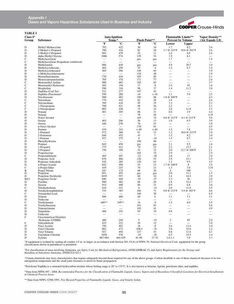
95COOPER CROUSE-HINDS CODE DIGEST
TABLE IClass I*Group Substance
Auto-IgnitionTemp.* Flash Point**
Flammable Limits**Percent by Volume
Vapor Density**(Air Equals 1.0)
°F °C °F °C Lower UpperD Methyl Methacrylate 792 422 50 10 1.7 8.2 3.6D 2-Methyl-1-Propanol 780 416 82 28 1.7 @ 123°F 10.6 @ 202°F 2.6D 2-Methyl-2-Propanol 892 478 52 11 2.4 8.0 2.6D alpha-Methyl Styrene 1066 574 129 54 1.9 6.1 —C Methylacetylene — — gas gas 1.7 — 1.4C Methylacetylene-Propadiene (stabilized) — — — — — — —D Methylamine 806 430 gas gas 4.9 20.7 1.0D Methylcyclohexane 482 250 25 -4 1.2 6.7 3.4D Methylcyclohexanol 565 296 149 65 — — 3.9D o-Methylcyclohexanone — — 118 48 — — 3.9D Monoethanolamine 770 410 185 85 — — 2.1D Monoisopropanolamine 705 374 171 77 — — 2.6C Monomethyl Aniline 900 482 185 85 — — 3.7C Monomethyl Hydrazine 382 194 17 -8 2.5 92 1.6C Morpholine 590 310 98 37 1.4 11.2 3.0D Naphtha (Coal Tar) 531 277 107 42 — — —D Naphtha (Petroleum)4 550 288 <0 <-18 1.1 5.9 2.5D Nitrobenzene 900 482 190 88 1.8 @ 200°F — 4.3C Nitroethane 778 414 82 28 3.4 — 2.6C Nitromethane 785 418 95 35 7.3 — 2.1C 1-Nitropropane 789 421 96 36 2.2 — 3.1C 2-Nitropropane 802 428 75 24 2.6 11.0 3.1D Nonane 401 205 88 31 0.8 2.9 4.4D Nonene — — 78 26 — — 4.35D Nonyl Alcohol — — 165 74 0.8 @ 212°F 6.1 @ 212°F 5.0D Octane 403 206 56 13 1.0 6.5 3.9D Octene 446 230 70 21 — — 3.9D n-Octyl Alcohol — — 178 81 — — 4.5D Pentane 470 243 <-40 <-40 1.5 7.8 2.5D 1-Pentanol 572 300 91 33 1.2 10.0 @ 212°F 3.0D 2-Pentanone 846 452 45 7 1.5 8.2 3.0D 1-Pentene 527 275 0 -18 1.5 8.7 2.4D Phenylhydrazine — — 190 88 — — —D Propane 842 450 gas gas 2.1 9.5 1.6D 1-Propanol 775 413 74 23 2.2 13.7 2.1D 2-Propanol 750 399 53 12 2.0 12.7 @ 200°F 2.1D Propiolactone — — 165 74 2.9 — 2.5C Propionaldehyde 405 207 -22 -30 2.6 17 2.0D Propionic Acid 870 466 126 52 2.9 12.1 2.5D Propionic Anhydride 545 285 145 63 1.3 9.5 4.5D n-Propyl Acetate 842 450 55 13 1.7 @ 100°F 8 3.5C n-Propyl Ether 419 215 70 21 1.3 7.0 3.53B Propyl Nitrate 347 175 68 20 2 100 —D Propylene 851 455 gas gas 2.0 11.1 1.5D Propylene Dichloride 1035 557 60 16 3.4 14.5 3.9B(C) Propylene Oxide1 840 449 -35 -37 2.3 36 2.0D Pyridine 900 482 68 20 1.8 12.4 2.7D Styrene 914 490 88 31 0.9 6.8 3.6C Tetrahydrofuran 610 321 6 -14 2.0 11.8 2.5D Tetrahydronaphthalene 725 385 160 71 0.8 @ 212°F 5.0 @ 302°F 4.6C Tetramethyl Lead — — 100 38 — — 6.5D Toluene 896 480 40 4 1.1 7.1 3.1D Tridecene — — — — — — —C Triethylamine 480** 249** 16 -9 1.2 8.0 3.5D Triethylbenzene — — 181 83 — — 5.6D Tripropylamine — — 105 41 — — 4.9D Turpentine 488 253 95 35 0.8 — —D Undecene — — — — — — —C Unsymmetrical Dimethyl
Hydrazine (UDMH) 480 249 5 -15 2 95 2.0C Valeraldehyde 432 222 54 12 — — 3.0D Vinyl Acetate 756 402 18 -8 2.6 13.4 3.0D Vinyl Chloride 882 472 -108.4 -78 3.6 33.0 2.2D Vinyl Toluene 921 494 127 53 0.8 11.0 4.1D Vinylidene Chloride 1058 570 -19 -28 6.5 15.5 3.4D Xylenes 867-984 464-529 81-90 27-32 1.0-1.1 7.0 3.71If equipment is isolated by sealing all conduit 1/2 in. or larger, in accordance with Section 501.15(A) of NFPA 70, National Electrical Code, equipment for the group classification shown in parentheses is permitted.
2For classification of areas involving Ammonia, see Safety Code for Mechanical Refrigeration, ANSI/ASHRAE 15, and Safety Requirements for the Storage and Handling of Anhydrous Ammonia, ANSl/CGA G2.1.
3 Certain chemicals may have characteristics that require safeguards beyond those required for any of the above groups. Carbon disulfide is one of these chemicals because of its low autoignition temperature and the small joint clearance to arrest its flame propagation.
4 Petroleum Naphtha is a saturated hydrocarbon mixture whose boiling range is 20° to 135°C. It is also known as benzine, ligroin, petroleum ether, and naphtha.
*Data from NFPA 497 - 2004, Recommended Practice for the Classification of Flammable Liquids, Gases, Vapors and of Hazardous (Classified) Locations for Electrical Installations in Chemical Process Areas.
**Data from NFPA 325M-1991, Fire Hazard Properties of Flammable Liquids, Gases, and Volatile Solids.
Appendix I Gases and Vapors Hazardous Substances Used in Business and Industry
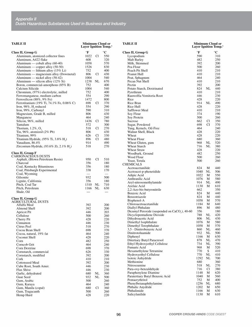
96 COOPER CROUSE-HINDS CODE DIGEST
TABLE II Minimum Cloud or Layer Ignition Temp.1
Class II, Group G °F °CAluminum, atomized collector fines 1022 Cl 550Aluminum, A422 flake 608 320Aluminum — cobalt alloy (60-40) 1058 570Aluminum — copper alloy (50-50) 1526 830Aluminum — lithium alloy (15% Li) 752 400Aluminum — magnesium alloy (Dowmetal) 806 Cl 430Aluminum — nickel alloy (58-42) 1004 540Aluminum — silicon alloy (12% Si) 1238 NL 670Boron, commercial-amorphous (85% B) 752 400Calcium Silicide 1004 540Chromium, (97%) electrolytic, milled 752 400Ferromanganese, medium carbon 554 290Ferrosilicon (88%, 9% Fe) 1472 800Ferrotitanium (19% Ti, 74.1% Fe, 0.06% C) 698 Cl 370Iron, 98%, H
2 reduced 554 290
Iron, 99%, Carbonyl 590 310Magnesium, Grade B, milled 806 430Manganese 464 240Silicon, 96%, milled 1436 Cl 780Tantalum 572 300Thorium, 1.2%, O
2518 Cl 270
Tin, 96%, atomized (2% Pb) 806 430Titanium, 99% 626 Cl 330Titanium Hydride, (95% Ti, 3.8% H
2) 896 Cl 480
Vanadium, 86.4% 914 490Zirconium Hydride, (93.6% Zr, 2.1% H
2) 518 270
Class II, Group FCARBONACEOUS DUSTS
Asphalt, (Blown Petroleum Resin) 950 CI 510Charcoal 356 180Coal, Kentucky Bituminous 356 180Coal, Pittsburgh Experimental 338 170Coal, Wyoming — —Gilsonite 932 500Lignite, California 356 180Pitch, Coal Tar 1310 NL 710Pitch, Petroleum 1166 NL 630Shale, Oil — —
Class II, Group GAGRICULTURAL DUSTS
Alfalfa Meal 392 200Almond Shell 392 200Apricot Pit 446 203Cellulose 500 260Cherry Pit 428 220Cinnamon 446 230Citrus Peel 518 270Cocoa Bean Shell 698 370Cocoa, natural, 19% fat 464 240Coconut Shell 428 220Corn 482 250Corncob Grit 464 240Corn Dextrine 698 370Cornstarch, commercial 626 330Cornstarch, modified 392 200Cork 410 210Cottonseed Meal 392 200Cube Root, South Amer. 446 230Flax Shive 446 230Garlic, dehydrated 680 NL 360Guar Seed 932 NL 500Gum, Arabic 500 260Gum, Karaya 464 240Gum, Manila (copal) 680 Cl 360Gum, Tragacanth 500 260Hemp Hurd 428 220
TABLE II Minimum Cloud or Layer Ignition Temp.1
Class II, Group G °F °CLycopodium 590 310Malt Barley 482 250Milk, Skimmed 392 200Pea Flour 500 260Peach Pit Shell 410 210Peanut Hull 410 210Peat, Sphagnum 464 240Pecan Nut Shell 410 210Pectin 392 200Potato Starch, Dextrinated 824 NL 440Pyrethrum 410 210Rauwolfia Vomitoria Root 446 230Rice 428 220Rice Bran 914 NL 490Rice Hull 428 220Safflower Meal 410 210Soy Flour 374 190Soy Protein 500 260Sucrose 662 Cl 350Sugar, Powdered 698 CI 370Tung, Kernels, Oil-Free 464 240Walnut Shell, Black 428 220Wheat 428 220Wheat Flour 680 360Wheat Gluten, gum 968 NL 520Wheat Starch 716 NL 380Wheat Straw 428 220Woodbark, Ground 482 250Wood Flour 500 260Yeast, Torula 500 260
CHEMICALSAcetoacetanilide 824 M 440Acetoacet-p-phenetidide 1040 NL 506Adipic Acid 1022 M 550Anthranilic Acid 1076 M 580Aryl-nitrosomethylamide 914 NL 490Azelaic Acid 1130 M 6102,2-Azo-bis-butyronitrile 662 350Benzoic Acid 824 M 440Benzotriazole 824 M 440Bisphenol-A 1058 M 570Chloroacetoacetanilide 1184 M 640Diallyl Phthalate 896 M 480Dicumyl Peroxide (suspended on CaCO
3), 40-60 356 180
Dicyclopentadiene Dioxide 788 NL 420Dihydroacetic Acid 806 NL 430Dimethyl lsophthalate 1076 M 580Dimethyl Terephthalate 1058 M 5703,5 - Dinitrobenzoic Acid 860 NL 460Dinitrotoluamide 932 NL 500Diphenyl 1166 M 630Ditertiary Butyl Paracresol 878 NL 470Ethyl Hydroxyethyl Cellulose 734 NL 390Fumaric Acid 968 M 520Hexamethylene Tetramine 770 S 410Hydroxyethyl Cellulose 770 NL 410lsotoic Anhydride 1292 NL 700Methionine 680 360Nitrosoamine 518 NL 270Para-oxy-benzaldehyde 716 Cl 380Paraphenylene Diamine 1148 M 620Paratertiary Butyl Benzoic Acid 1040 M 560Pentaerythritol 752 M 400Phenylbetanaphthylamine 1256 NL 680Phthalic Anydride 1202 M 650Phthalimide 1166 M 630Salicylanilide 1130 M 610
Appendix II Dusts Hazardous Substances Used in Business and Industry

97COOPER CROUSE-HINDS CODE DIGEST
TABLE II Minimum Cloud or Layer Ignition Temp.1
Class II, Group G °F °CSorbic Acid 860 460Stearic Acid, Aluminum Salt 572 300Stearic Acid, Zinc Salt 950 M 510Sulfur 428 220Terephthalic Acid 1256 NL 680
DRUGS2-Acetylamino-5-nitrothiazole 842 4502-Amino-5-nitrothiazole 860 460Aspirin 1220 M 660Gulasonic Acid, Diacetone 788 NL 420Mannitol 860 M 460Nitropyridone 806 M 4301-Sorbose 698 M 370Vitamin B1, mononitrate 680 NL 360Vitamin C (Ascorbic Acid) 536 280
DYES, PIGMENTS, INTERMEDIATESBeta-naphthalene-azo-Dimethylaniline 347 347 175Green Base Harmon Dye 347 347 175Red Dye Intermediate 347 347 175Violet 200 Dye 347 347 175
PESTICIDESBenzethonium Chloride 716 CI 380Bis(2-Hydroxy-5-chlorophenyl) methane 1058 NL 570Crag No. 974 590 Cl 310Dieldrin (20%) 1022 NL 5502, 6-Ditertiary-butyl-paracresol 788 NL 420Dithane 356 180Ferbam 302 150Manganese Vancide 2448 120Sevin 284 140
- Trithiobis (N,N-Dimethylthio-formamide) 446 230THERMOPLASTlC RESINS AND MOLDING COMPOUNDS
Acetal ResinsAcetal, Linear (Polyformaldehyde) 824 NL 440
Acrylic ResinsAcrylamide Polymer 464 240Acrylonitrile Polymer 860 460Acrylonitrile-Vinyl Pyridine Copolymer 464 240Acrylonitrile-Vinyl Chloride-Vinylidene Chloride Copolymer (70-20-10) 410 210
Methyl Methacrylate Polymer 824 NL 440Methyl Methacrylate-Ethyl Acrylate Copolymer 896 NL 408
Methyl Methacrylate-Ethyl Acrylate-StyreneCopolymer
824 NL 440
Methyl Methacrylate-Styrene-Butadiene-Acrylonitrile Copolymer 896 NL 480
Methacrylic Acid Polymer 554 290Cellulosic Resins
Cellulose Acetate 644 340Cellulose Triacetate 806 NL 430Cellulose Acetate Butyrate 698 NL 370Cellulose Propionate 860 NL 460Ethyl Cellulose 608 CI 320Methyl Cellulose 644 340
TABLE II Minimum Cloud or Layer Ignition Temp.1
Class II, Group G °F °CCarboxymethyl Cellulose 554 290Hydroxyethyl Cellulose 644 340
Chlorinated Polyether ResinsChlorinated Polyether Alcohol 806 460
Nylon (Polyamide) ResinsNylon Polymer (Polyhexa-methylene Adipamide) 806 430
Polycarbonate ResinsPolycarbonate 1310 NL 710
Polyethylene ResinsPolyethylene, High Pressure Process 716 380Polyethylene, Low Pressure Process 788 NL 420Polyethylene Wax 752 NL 400
Polymethylene ResinsCarboxypolymethylene 968 NL 520
Polypropylene ResinsPolypropylene (No Antioxidant) 788 NL 420
Rayon ResinsRayon (Viscose) Flock 482 250
Styrene ResinsPolystyrene Molding Cmpd. 1040 NL 560Polystyrene Latex 932 500Styrene-Acrylonitrile (70-30) 932 NL 500Styrene-Butadiene Latex (>75% Styrene; Alum Coagulated) 824 NL 440
Vinyl ResinsPolyvinyl Acetate 1022 NL 550Polyvinyl Acetate/Alcohol 824 440Polyvinyl Butyral 734 NL 390Vinyl Chloride-Acrylonitrile Copolymer 878 470Polyvinyl Chloride-Dioctyl Phthalate Mixture 608 NL 320Vinyl Toluene-Acrylonitrile Butadiene Copolymer 936 NL 530
THERMOSETTlNG RESINS AND MOLDING COMPOUNDSAllyl Resins
Allyl Alcohol Derivative (CR-39) 932 NL 500Amino Resins
Urea Formaldehyde Molding Compound 860 NL 460Urea Formaldehyde-Phenol Formaldehyde Molding Compound (Wood Flour Filler) 464 240
Epoxy ResinsEpoxy 1004 NL 540Epoxy - Bisphenol A 950 NL 510Phenol Furfural 590 310
Phenolic ResinsPhenol Formaldehyde 1076 NL 580Phenol Formaldehyde Molding Cmpd. (Wood Flour Filler) 932 NL 500
Phenol Formaldehyde, Polyalkylene- Polyamine Modified 554 290
Polyester ResinsPolyethylene Terephthalate 1076 NL 580Styrene Modified Polyester-Glass Fiber Mixture 680 360
Polyurethane ResinsPolyurethane Foam, No Fire Retardant 824 440Polyurethane Foam, Fire Retardant 734 390
SPECIAL RESINS AND MOLDING COMPOUNDSAlkyl Ketone Dimer Sizing Compound 320 160Cashew Oil, Phenolic, Hard 356 180Chlorinated Phenol 1058 NL 570Coumarone-lndene, Hard 968 NL 520Ethylene Oxide Polymer 662 NL 350Ethylene-Maleic Anhydride Copolymer 1004 NL 540Lignin, Hydrolized, Wood-Type, Fines 842 NL 450Petrin Acrylate Monomer 428 NL 220Petroleum Resin (Blown Asphalt) 932 500Rosin, DK 734 NL 390Rubber, Crude, Hard 662 NL 350Rubber, Synthetic, Hard (33% S) 608 NL 320Shellac 752 NL 400Sodium Resinate 428 220Styrene — Maleic Anhydride Copolymer 878 CI 470
1Normally, the minimum ignition temperature of a layer of a specific dust is lower than the minimum ignition temperature of a cloud of that dust. Since this is not universally true, the lower of the two minimum ignition temperatures is listed. If no symbol appears between the two temperature columns, then the layer ignition temperature is shown. “Cl” means the cloud ignition temperature is shown. “NL” means that no layer ignition temperature is available and the cloud ignition temperature is shown. “M” signifies that the dust layer melts before it ignites; the cloud ignition temperature is shown. “S” signifies that the dust layer sublimes before it ignites; the cloud ignition temperature is shown. 2Certain metal dusts may have characteristics that require safe-guards beyond those required for atmospheres containing the dusts of aluminum, magnesium, and their commercial alloys. For example, zirconium, thorium, and uranium dusts have extremely low ignition temperatures (as low as 20°C) and minimum ignition energies lower than any material classified in any of the Class I or Class II groups.
Data from NFPA 499 - 2004, Recommended Practice for the Classification of Combustible Dusts and of Hazardous (Classified) Locations for Electrical Installations in Chemical Process Areas.
Appendix II Dusts Hazardous Substances Used in Business and Industry

98 COOPER CROUSE-HINDS CODE DIGEST
A. Need for Seals and Drains. 1. Seals
EYS and EZS sealing fittings:
electrical installation to another at atmospheric pressure and normal ambient temperatures.
While not an NEC requirement, many engineers consider it good prac-tice to sectionalize long conduit runs by inserting seals not more than 50 to 100 feet apart, depending on the conduit size, to minimize the effects of “pressure piling.”
Sealing fittings are required:
when used in Class I, Division 1 and 2 hazardous locations. To be located as close as practicable and, in no case, more than 18" from such enclosures. The enclosure's installation instructions may specify a distance less than 18".
terminals, splices, or taps when used in Class I, Division 1 hazardous locations. To be located as close as practicable and, in no case, more than 18" from such enclosures.
hazardous locations.
explosionproof.
a Class I, Division 2 location if they are attached to process equip-ment that may cause a pressure of over 6 in. of water to be exerted on a cable end.
The NEC in Section 502.15 requires seals in Class II locations under certain conditions. Cooper Crouse-Hinds sealing fittings can be used to meet this requirement, although there are other acceptable methods.
2. Drains
In humid atmospheres or in wet locations, where it is likely that water can gain entrance to the interiors of enclosures or raceways, the race-ways should be inclined so that water will not collect in enclosures or on seals but will be led to low points where it may pass out through ECD drains.
Frequently the arrangement of raceway runs makes this method impractical if not impossible. In such instances Type EZD drain seal fittings should be used. These fittings prevent harmful accumulations of water above the seal. See Section 501.15(F).
In locations which usually are considered dry, surprising amounts of water frequently collect in conduit systems. No conduit system is airtight; therefore, it may “breathe.” Alternate increases and decreases in temperature and/or barometric pressure due to weather changes or due to the nature of the process carried on in the location where the conduit is installed will cause “breathing.”
Outside air is drawn into the conduit system when it “breathes” in. If this air carries sufficient moisture it will be condensed within the system when the temperature decreases and chills this air. The internal conditions being unfavorable to evaporation, the resultant water accu-mulation will remain and be added to by repetitions of the breathing cycle.
In view of this likelihood, it is good practice to insure against such water accumulations and probable subsequent insulation failures by
installing EZD with drain cover or EZD with inspection cover even though conditions prevailing at the time of planning or installing do not indicate their need.
B. Selection of Seals and Drains.1. Primary Considerations
(a) Select the proper sealing fitting for the hazardous vapor involved; i.e., Class I, Groups A, B, C, or D.
(b) Select a sealing fitting for the proper use with respect to mounting position. This is particularly critical when the conduit runs between hazardous and nonhazardous areas. Improper positioning of a seal may permit hazardous gases or vapors to enter the system beyond the seal, and permit them to escape into another portion of the hazardous area, or to enter a nonhazardous area. Some seals are designed to be mounted in any position; others are restricted to horizontal or vertical mounting.
(c) Install the seals on the proper side of the partition or wall as recom-mended by the manufacturer. See “Installation Diagram for Sealing” in Appendix IV.
(d) Installation of seals should be made only by trained personnel in strict compliance with the instruction sheets furnished with the seals and sealing compound.
Therefore, it would be wise to incorporate precautionary notes on installation diagrams to stress the importance of following instructions. See “Sealing Compound and Dams” in this Appendix.
(e) It should be noted that Section 501.15(C)(4) prohibits splices or taps in sealing fittings.
(f) Cooper Crouse-Hinds sealing fittings are listed by Underwriters Laboratories Inc. for use in Class I hazardous locations with Cooper Crouse-Hinds sealing compounds only, both CHICO A and CHICO Speedseal. These compounds, when properly mixed and poured, harden into a dense, strong mass which is insoluble in water, is not attacked by chemicals, and is not softened by heat. It will withstand with ample safety factor, pressure of the exploding trapped gases or vapor.
(g) Conductors sealed in the compound may be approved thermoplastic or rubber insulated type. Both may or may not be lead covered. (The lead need not be removed.) Caution: CHICO A and CHICO SpeedSeal are not electrically insulating compounds; therefore, they should not be so used.
2. Types of Sealing Fittings
The following sealing fittings meet the requirements of the NEC when properly installed.
(a) EYS Sealing Fittings
One style of EYS sealing fittings are for use with vertical or nearly vertical conduit in sizes from 1/2" through 1".
Other styles are available in sizes 1/2" through 6" for use in vertical or horizontal conduits. In horizontal runs, these are limited to face up openings.
Sizes from 1-1/4" through 6" have extra large work openings, and separate filling holes, so that CHlCO X fiber dams are easy to make. Overall diameter of sizes 1-1/4" through 6" is scarcely greater than that of unions of corresponding sizes, permitting close conduit spacings.
Appendix III Selection of Seals and Drains

99COOPER CROUSE-HINDS CODE DIGEST
(b) EZS Sealing Fittings
EZS seals are for use with conduit running at any angle, from vertical through horizontal.
(c) EYD Drain Seal Fittings
EYD drain seals provide continuous draining and thereby prevent water accumulation. EYD seals are for vertical conduit runs and range in size from 1/2" to 4" inclusive.
They are provided with one opening for draining and one for filling, a rubber tube to form drain passage and an ECD drain fitting.
(d) EZD with Drain/Inspection Cover
EZD drain seals provide continuous drainingand thereby prevent water accumulation.
The covers should be positioned so that the drain will be at the bottom. A set screw is provided for locking the cover in this position.
EZD fittings are suitable for sealing vertical conduit runs between hazardous and nonhazardous areas, but must be installed in the hazardous area when it is above the nonhazardous area. They must be installed in the nonhazardous area when it is above the hazardous area. Otherwise, the drain might communicate gases or vapors from the hazardous area into a portion of the conduit system in the nonhaz-ardous area, a very unsafe situation. This applies to any drain seal.
EZD drain/inspection seals are designed so that the covers can be removed readily, permitting inspection during installation or at any time thereafter. After the fittings have been installed in the conduit run and conductors are in place, the cover and barrier are removed. After the dam has been made in lower hub opening with CHICO® X fiber the barrier must be replaced before the CHICO A sealing compound can be poured into the sealing chamber.
(e) EYSR Retrofit seals
Cooper Crouse-Hinds EYSR Retrofit Sealing Fittings offer a low-cost solution to replacing installed Cooper Crouse-Hinds EYS and EYD sealing fittings during the rewiring or expansion of an electrical system.
The EYSR allows rewiring or expanding an electrical system without disassembling the conduit system, reducing labor costs and downtime.
Made of Feraloy® iron alloy or optional copper-free aluminum, the EYSR is available in 3/4" to 4" NPT sizes, and is CSA certified for use in Class I, Division 2 hazardous (classified) locations.
C. Sealing Compound and Dams.Conduit seals should be made only by trained personnel in strict compli-ance with the specific instruction sheets provided with each sealing fitting. Improperly made seals are worthless.
Cooper Crouse-Hinds CHICO® A and CHICO SpeedSeal sealing compounds are the only sealing compounds approved for use with Cooper Crouse-Hinds sealing fittings.
Following the procedures and precautions outlined below, and the specific instructions packed with each sealing fitting, “CHICO A” and CHICO SpeedSeal will provide seals that do their intended job: namely, restrict the passage of gases, vapors, or flames from one part of the electrical system to another at atmospheric pressure and normal ambient temperatures.
1. Dams
The first requirement for pouring a high quality CHICO A seal is a well made dam. Improperly packed or weak dams permit a loss of compound into conduit systems, which both wastes compound and makes an unsafe seal.
(a) When damming horizontal seals, prepare a dam in each conduit hub except the upper hub of vertical seals.
(b) Using the EYS-Tool-Kit, force the conductors towards the filling opening.*
Cooper Crouse-Hinds recommends the use of the EYS-Tool-Kit when preparing a fiber dam. The EYS-Tool-Kit comes with five patented tools for wedging and lifting conductors, packing fiber and inspection of the fiber dam.
(c) Pack fiber (CHICO X) into each conduit hub in the sealing fitting, except for the upper hub of vertical seals.
(d) Push the conductors away from the filling opening and force them apart so that they do not lay in contact with each other along their length. If the conductors are in contact, the sealing compound will not form a closed path between them.
(e) Force the damming material (CHICO X fiber) between each conductor and between the conductors and the hubs and/or integral bushing. Remember that the dam has to be strong enough and tight enough to prevent a considerable weight of fluid sealing compound from seeping out.
(f) Push shreds of packing away from the conductors to prevent gas leakage paths. Care must be used so as not to damage the conductor insulation.
(g) The completed dam should be even with the integral bushing.
2. Sealing Compound(a) Use of CHlCO® A
CHlCO A sealing compound is listed by UL for making seals in Cooper Crouse-Hinds fittings. The insulation on the conductors sealed in the compound may be approved thermoplastic or rubber, with or without lead covering.
This is not an electrically insulating compound and should not be used for this purpose. CHICO A is not affected by gasoline, alcohol, acetone, ether, naphtha, petroleum, benzol, or lacquer solvent.
(b) Preparation of CHlCO A
The following cautions are to be observed when preparing CHICO A sealing compound for pouring a seal:
(1) Use a clean mixing vessel for every batch. Particles of previous batches or dirt will spoil the seal.
(2) Recommended proportions are by volume – two parts of CHlCO A to one part clean water. Slight deviations in these proportions will not affect the result.
(3) Do not mix more than can be poured in 15 minutes after water is added. Use cold water. Warm water increases setting speed. Stir immedi-ately and thoroughly.
(4) If batch starts to set do not attempt to thin it by adding water or by stirring. Such a procedure will spoil seal. Discard partially set material and make fresh batch. After pouring, close opening immediately.
Appendix III Selection of Seals and Drains

100 COOPER CROUSE-HINDS CODE DIGEST
(5) Do not pour compound in sub-freezing temperatures, or when these temperatures will occur during curing.
(6) See that compound level is in accordance with the instruction sheet for that specific fitting.
(c) Use of CHICO SpeedSeal Compound
With CHICO SpeedSeal, it is not necessary to prepare a dam for hori-zontal applications or separate the conductors in the sealing fitting, making for a much easier and faster job.
EZDWith drain/inspection cover1/2 – 2 inch
EZS1/2 – 3 inchFor sealing at any angle
EYD Drain seal1/2 – 1 inch
EYSX Expanded all fmale HUB 1/2 – 4 inch
EYD Drain seal1 1/4 – 4 inch
EYSX Expanded all female HUB 1/2 – 4 inch
EYS Elbow seal3/4-inch
EYSR3/4- 4 inchRetrofit sealing fitting
A few of the sealing fittings available from Crouse-Hinds.
A few of the drains, breathers, and sealing fittings available from Cooper Crouse-Hinds.
ECD 18“Combination” Breather and drain CI. I, Gr. C, D CI. II, Gr. F, G CI. III
ECD 16Breather/Drain CI. I, Gr. B, C, DCI. II, Gr. E, F, GCI. III
ECD 11 or 281Drain CI. I, Gr.C, DCI. II, Gr. E, F, GCI. III
ECD 13BreatherCI. I, Gr. C, DCI. II, Gr. E, F, GCI. III
ECD 15 “Universal” Breather or drainCI. I, Gr. C, DCI. II, Gr. G(Most effective for these applications)
EYS Tool Kit
Appendix III Selection of Seals and Drains

101COOPER CROUSE-HINDS CODE DIGEST
Cooper Crouse-Hinds Sealing Compound products.
EZS – Horizontal seal
Chico A compound
Chico X fiber dam
CHICO A-P INTRAPAK ®
premeasured sealing compound and water in plastic mixing pouch
CHICO A Sealing compound
CHICO X Fiber CHICO® Speedseal™ compound
Chico A compound
Chico X fiber dam
EYS – Vertical sealing
Chico A compound
Chico X fiber
EYS – Horizontal seal
Seals made with CHICO A Sealing Compound and CHICO X Fiber.
CHICO® Speedseal™ compound lets you reliably install a complete explosionproof seal in less than five minutes. Just pump to mix, inject the pre-measured amount, replace the plug and the fitting is sealed.
Appendix III Selection of Seals and Drains

102 COOPER CROUSE-HINDS CODE DIGEST
Explosionproof Enclosure which must be sealed
Explosionproof Enclosure which must be sealed
Explosionproof Enclosure which must be sealed
Explosionproof Enclosure which must be sealed
EYS seal of this type may be used inside or outside of Class I area.
EZS seal of this type may be used inside or outside of Class I area.
Note:EYS seal D in this position may be used either inside or outside of Class I area.
Junction Box
Class I, Div.1 Area
or ClassI, Div.2
Area
Area of Laser
Hazard
Area of Laser Hazard
EZD and EYD seals in this position must be placed outside of Class I area. See Appendix III, Para. B.2.(d).
EZD and EYD seals in this position must be placed inside of Class I area. See Appendix III, Para. B.2.(d).
(A) EZD drain seals are available in 1/2 – 2 inch conduit sizes for
vertical conduits only.
(B) EYD drain seals are available in 1/2 – 4 inch conduit sizes for
vertical conduits only.
(C) EZS seals of this form are available in 1/2 – 3 inch conduit sizes
for vertical or horizontal conduits.
(D) EYS seals of this form are available in 1/2 – 6 inch conduit sizes
for vertical or horizontal conduits.
(E) EYS seals of this form are available in 1/2 – 1 inch conduit sizes
for vertical conduits.
Appendix IVInstallation Diagram for Sealing

103COOPER CROUSE-HINDS CODE DIGEST
* North American wiring practices allow the use of MC cable or rigid conduit for Zone 1 hazardous areas. When entering a non-metallic enclosure, use a Zone 1 Myers hub. If the installation requires MC cable, use TMC/TMCX Terminator connectors.
NON-HAZARDOUS AREA
HAZARDOUS AREA
FEEDER
EYS
Key to Numerals*1. eLLK or FVS Fluorescent Luminaire with TMC Terminator™ cable
gland
2. eAZK Lighting Junction Box with Zone 1 Myers® hubs
3. EVLP or EVMA HID Luminaire with TMC Terminator cable gland
4. GHG Switched IEC 309 Receptacle with Zone 1 Myers hubs
5. GHG 273 Ex Push-Button Control Station with Zone 1 Myers hubs
6. GHG 44 Control Panel with Zone 1 Myers hubs
7. GHG 744 Terminal Box with Zone 1 Myers hubs
8. EXKO Molded Plastic Distribution Panel with Zone 1 Myers hubs
9. N2RS Control Switch with TMC Terminator cable gland
10. GHG 981 Socket Distribution Panel with Zone 1 Myers hubs
11. GHG Interlocked IEC 309 Receptacle with Zone 1 Myers hubs
12. EXKO Molded Plastic Distribution Panel with Zone 1 Myers hubs
13. FSQC Arktite Interlocked Receptacle with TMCX Terminator cable gland
14. GHG 635 Manual Motor Starter with Zone 1 Myers hubs
15. EBMS Magnetic Motor Starter with TMCX Terminator cable gland
16. N2SCU SpecOne™ Control Station with Zone 1 Myers hubs
17. GHG 43 SpecOne Control Station with Zone 1 Myers hubs
18. EDS Motor Starter with TMCX Terminator cable gland
19. Zone 1 Rated Motor with TMC or TMCX Terminator cable gland
Appendix V Diagram for Class I, Zone 1 Power & Lighting Installation

104 COOPER CROUSE-HINDS CODE DIGEST
Key to Numerals1 Sealing fitting. EYS for horizontal or vertical.
2 Sealing fitting. EZS for vertical or horizontal conduits.
3 Circuit breaker. Type EBM.
4 Panelboard. EXDC/EPL. Branch circuits are factory sealed. No seals required in mains or branches unless 2" or over in size.
5 Junction box. Series GUA, GUB, EAJ, EAB have threaded covers. Series CPS has ground flat surface covers.
6 Fixture hanger. EFHC, GUAC, or EFH.
7 Lighting Fixture. EV Series incandescent and EVM Series. H.I.D.
8 Flexible fixture support. ECHF.
9 Fluorescent fixture. EVFT.
1112 ETW explosionproof telephone.
13 Plug receptacle. CES delayed action.
14 Plug receptacle. FSQ. Interlocked with switch.
15 Breather. ECD.
16 Drain. ECD.
17 Union. UNY.
18 Switch. Series EFS.
19 Instrument enclosure. EIH.
20 Manual line starter. EMN.
21 Motors. Explosionproof.
22 Emergency lighting system. ELPS.
23 ETC Power Relay.
National Electrical Code Referencesa Sec. 501.15(A)(4). Seal required where conduit passes from hazardous to nonhazardous area.
b Sec. 501.15(A)(1)(1). Seals required within 18 inches of all arcing devices.
c Sec. 408.36. Circuit breaker protection required ahead of panelboard.
d Sec. 501.15(A)(1)(2). Seals required if conduit is 2 inches or larger.
e Sec. 501.115(A). All arcing devices must be explosionproof.
f Sec. 501.10(A). All boxes must be explosionproof and threaded for rigid or IMC conduit.
g Sec. 501.130(A)(4). All boxes and fittings for support of luminaires must be approved for Class I locations.
h Sec. 501.130(A)(1). All lighting fixtures, fixed or portable, must be explosionproof.
i Sec. 501.130(A)(3). Pendant fixture stems must be threaded rigid or IMC conduit. Conduit stems if over 12 inches must have flexible connector, or must be braced.
j Sec. 501.150(A). All signal and alarm equipment irrespective of voltage must be approved for Class I, Division 1 locations.
k Sec. 501.145. Receptacles and plugs must be explosionproof and provide grounding connectionsfor portable equipment.
l Sec. 501.15(F)(1). Breathers and drains needed in all humid locations.
m Sec. 501.10(A). All joints and fittings must be explosionproof.
n Sec. 501.125(A). Motor must be suitable for Class I.
p Art. 430. Motor overcurrent protection.
*Also applicable for Class I, Zone 1, see 505.15(B)
Appendix VI Diagram for Class I, Div. 1* Lighting Installation
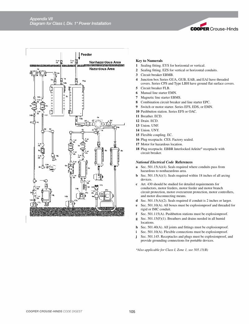
105COOPER CROUSE-HINDS CODE DIGEST
Key to Numerals1 Sealing fitting. EYS for horizontal or vertical.
2 Sealing fitting. EZS for vertical or horizontal conduits.
3 Circuit breaker EBMB.
4 Junction box Series GUA, GUB, EAB, and EAJ have threaded covers. Series CPS and Type LBH have ground flat surface covers.
5 Circuit breaker FLB.
6 Manual line starter EMN.
7 Magnetic line starter EBMS.
8 Combination circuit breaker and line starter EPC.
9 Switch or motor starter. Series EFS, EDS, or EMN.
10 Pushbutton station. Series EFS or OAC.
11 Breather. ECD.
12 Drain. ECD.
13 Union. UNF.
14 Union. UNY.
15 Flexible coupling. EC.
16 Plug receptacle. CES. Factory sealed.
17 Motor for hazardous location.
18 Plug receptacle. EBBR Interlocked Arktite® receptacle with circuit breaker.
National Electrical Code Referencesa Sec. 501.15(A)(4). Seals required where conduits pass from hazardous to nonhazardous area.
b Sec. 501.15(A)(1). Seals required within 18 inches of all arcing devices.
c Art. 430 should be studied for detailed requirements for conductors, motor feeders, motor feeder and motor branch circuit protection, motor overcurrent protection, motor controllers, and motor disconnecting means.
d Sec. 501.15(A)(2). Seals required if conduit is 2 inches or larger.
e Sec. 501.10(A). All boxes must be explosionproof and threaded for rigid or IMC conduit.
f Sec. 501.115(A). Pushbutton stations must be explosionproof.
g Sec. 501.15(F)(1). Breathers and drains needed in all humid locations.
h Sec. 501.40(A). All joints and fittings must be explosionproof.
i Sec. 501.10(A). Flexible connections must be explosionproof.
j Sec. 501.145. Receptacles and plugs must be explosionproof, and provide grounding connections for portable devices.
*Also applicable for Class I, Zone 1, see 505.15(B)
8c8c
Appendix VII Diagram for Class I, Div. 1* Power Installation

106 COOPER CROUSE-HINDS CODE DIGEST
Key to Numerals1 Sealing fitting. EYS for horizontal or vertical.
2 Sealing fitting. EZS for vertical or horizontal conduits.
3 Circuit breaker. Type EPC.
4 Panelboard. D2PB, N2PB. Branch circuits are factory sealed.
5 Junction box or conduit fitting. NJB, Condulet®.
6 Fixture hanger. AHG, GS, UNJ.
7 Lighting fixture. VMV, DMV, and LMV (CHAMP®).
8 Flexible fixture support. ECHF.
9 Handlamp. EVH.
1112 Compact fluorescent lighting fixture. FVS.
13 Plug receptacle. CES delayed action.
14 Plug receptacle. ENR or CPS delayed action with GFS-1 ground fault circuit interrupter.
15 Breather. ECD.
16 Drain. ECD.
17 Union. UNY.
18 Switch. Series EFS.
19 Magnetic line starter. EBMS.
20 Manual line starter. EMN.
21 Motors. Suitable for Class I, Division 2 locations.
22 Emergency lighting system. N2LPS.
23 Fluorescent fixture. FVN.
24 Floodlight. FMV.
National Electrical Code Referencesa Sec. 501.15(B)(2). Seal required where conduit passes from hazardous to non-hazardous area.
b Sec. 501.15(B)(1). Seals required within 18 inches of all arcing devices.
c Sec. 408.36. Circuit breaker protection required ahead of panelboard.
d Sec. 501.130(B)(2). All fixed lighting fixtures shall be enclosed and gasketed and not exceed ignition temperature of the gas.
e Sec. 501.115(B)(1). Most arcing devices must be explosionproof.
f Sec. 501.10(B). All boxes must be threaded for rigid or IMC conduit.
h Sec. 501.130(B)(1). All portable lighting fixtures must be explosion proof.
i Sec. 501.130(B)(3). Pendant fixture stems must be threaded rigid conduit or IMC. Rigid stems if over 12 inches must have flexible connector, or must be braced.
j Sec. 501.150(B). All signaling equipment must be approved for Class I location.
k Sec. 501.145. Receptacles and plugs must be explosionproof and provide grounding connections for portable equipment.
l Sec. 501.15(F)(1). Breathers and drains needed in all humid locations.
m Sec. 501.10(B). Not all joints and fittings are required to be explosionproof.
n Sec. 501.125(B). Motor shall be suitable for Division 2.
p Art. 430. Motor overcurrent protection.
*Also applicable for Class I, Zone 2
Appendix VIII Diagram for Class I, Div. 2* Power & Lighting Installation

107COOPER CROUSE-HINDS CODE DIGEST
Appendix IX Diagram for Class II Lighting Installation

108 COOPER CROUSE-HINDS CODE DIGEST
Appendix X Diagram for Class II Power Installation

109COOPER CROUSE-HINDS CODE DIGEST
Note: Not all types listed are suitable for use in all four groups for Class I hazardous locations. Consult catalog listing pages for applicable classes and groups.
Class I Div. 1*
Class I Div. 1*
Class II Div. 1
Class II Div. 2
Class III Div. 1
Class III Div. 2
GroupsE & F
GroupG
Conduit bodies and junction boxes
CPS EC EJB EJH EKC GUB, EABEAJ UNF/UNY UNFL/UNYL
Form 7 Series,Form 8, Mark 9, Moguls, FS/FD, W-Series, NJB and all products shown under ClassI, Division1
CPS EC EJB EJH EKC GUB, EABEAJ UNF/UNY UNFL/UNYL
Same if splices, taps, etc.
Dusttight Form 7 Series, Form 8, Mark 9, Moguls, FS/FD, W-Series, and all products shown uder Class II, Division 1
Switches EDS, EFD, EFS, EHS, FLS, FSPC, GUSC, OAC, AF Series, GHG620 Series
Panelboards EPL ESPBH EWP EXD GUSC LP1
D2PB, D2Z D2D D2L ESPBH GUSC LP2 N2PB
EPL ESPBH EXD GUSC
All products shown under ClassII, Division 1
Lighting fixtures ELPS EVI EVF EVFDR EVH EVP
® RCDE EVFT
FMV CHAMP®
DMV CHAMP®
FVN LMV CHAMP® NDA Vaporgard ™
VMV CHAMP®
VSeries N2LPS FVS N2MV
EVFT EVP
DMV CHAMP®
EVI EVF EVFDR EXL FVN
®
LMV CHAMP®
VMV CHAMP®
ELPS FVS
Fixture hangers COUP CPS EAHC EC EFHC EFHX GUA UNR
AHG EC UNE UNH UNJ UNJC
CPS EC EAHC EFHC EFHX GUA UNR
Plugs and receptacles APJ, BHP, BHR, CES, CESD, CPH, CPP, CPS, DR, ENP, ENR, FP, FSQ, NPJ, SRD, SP
Groups F, G only APJ, BHP, BHR DR, ENP, ENR, FP, FSQ, NPJ, SRD, SP
Interlocked plug receptacles BHR, C2SR, EPC, FSQ, SRD Groups F, G only BHR, DBR, EPC, FSQ, SRD, EBBR
Control stations and pilot lights EDS, EFD, EFS, EMP, OAC, N2S (Class I, Division 2 only), FlexStation™, DSD-SR
Industrial control EDS, EFD, EFS, EMN, EPC, EPCB, FSPC, OAC, EBM
Circuit breakers EDS, EFD, EPC, EPCB, FLB, GUSC EDS, EFD, EPC, FLB, GUSC, EBM,
Telephones, instruments and signals
EMH, ESR, ETW and D2TW Telephones, ETH, ETH ™ Device, EXSO Steady on beacons, EXR Rotating beacon, EXS strobe light, GUB (W2H for Class I, Division 2), EIH, EIHT
*Also suitable for Class I, Zone 1, see 505.15(B) and 505.20 (B) †Also suitable for Class I, Zone 2, see 505.15(C) and 505.20 (C)
Appendix XI“Quick Selector” Electrical Equipment for Hazardous Locations

110 COOPER CROUSE-HINDS CODE DIGEST
HAZARDOUS AREA AND
EQUIPMENT PROTECTION REFERENCE
Global Reference Guide for Potentially Explosive
Atmospheres and Hazardous Locations

111COOPER CROUSE-HINDS CODE DIGEST
Explosion Protected—Product is designed for explosion
Apparatus Group —ATEX Equipment Group
Category—ATEX Equipment Category
Explosive Atmosphere Suitability (G —Gas, vapor or mist)
Explosive Atmosphere Suitability(D—Dust)
Ingress Protection (IP) Codes
Surface Temperature Classification
Explosion Protection Standard(EX-IEC/CEC, Eex-CENELEC, Aex-NEC)
Method of Explosion Protection
Hazardous Atmosphere Category(Gas Grouping)
Temperature Classification
ATEX Required Markings CENELEC Required Markings
Ex II 2 G D IP65 55°C EX e IIC T6
Typical ATEX Product Markings (Per ATEX Directive 94/9/EC)
Typical [ATEX (94/9/EC)] Nameplate Marking
CE marking and number of Notified Body responsible for Quality System (CE 0359)
Serial number including year of manufacture
Explosion protection marking
Certificate numberMay end with U—Component certMay end with X—Special conditions for safe use
Equipment Group (II) and Category (2)
Type of explosive atmosphereG—gas, vapor or mistD—dust
Other essential information required by Standards used
Ambient temperature (-20°C to +40°C marking is not required)
Electrical parameters
Name and address of manufacturer
Warnings
Type designation
ATEX Equipment Group / ATEX Equipment Category (ATEX 94/9/EC)
ATEX Equipment Group ATEX Equipment Category Suitable for Use in Atmospheres
Made Explosive by:
Protection Level Required Protection Performance
& Operation
I (Mines) M1 Methane & Dust Very High Two faults, remain
energized & functioning
I (Mines) M21 Methane & Dust High Severe normal operation, de-energized in exp. atm.
II (Above Ground) 1 Gas, Vapor, Mist—Zone 0; Dust—Zone 20 Very High Two faults
II (Above Ground) 2 Gas, Vapor, Mist—Zone 1; Dust—Zone 21 High One fault
II (Above Ground) 3 Gas, Vapor, Mist—Zone 2; Dust—Zone 22 Low Normal operation
ATEX/IEC/NEC/CEC Reference
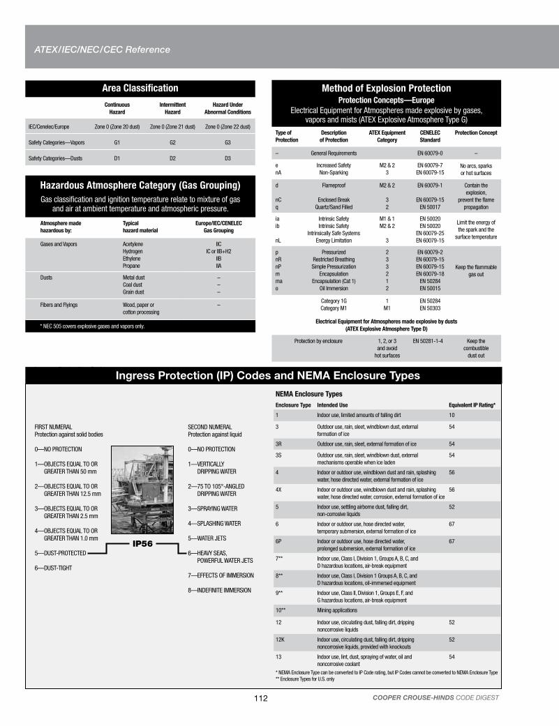
112 COOPER CROUSE-HINDS CODE DIGEST
Ingress Protection (IP) Codes and NEMA Enclosure Types
Area Classification
Continuous
Hazard
Intermittent
Hazard
Hazard Under
Abnormal Conditions
IEC/Cenelec/Europe Zone 0 (Zone 20 dust) Zone 0 (Zone 21 dust) Zone 0 (Zone 22 dust)
Safety Categories—Vapors G1 G2 G3
Safety Categories—Dusts D1 D2 D3
Hazardous Atmosphere Category (Gas Grouping)
Gas classification and ignition temperature relate to mixture of gas and air at ambient temperature and atmospheric pressure.
Atmosphere made
hazardous by:
Typical
hazard material
Europe/IEC/CENELEC
Gas Grouping
Gases and Vapors Acetylene
Hydrogen
Ethylene
Propane
IIC
IC or IIB+H2
IIB
IIA
Dusts Metal dust
Coal dust
Grain dust
–
–
–
Fibers and Flyings Wood, paper or
cotton processing
–
* NEC 505 covers explosive gases and vapors only.
Method of Explosion ProtectionProtection Concepts—Europe
Electrical Equipment for Atmospheres made explosive by gases, vapors and mists (ATEX Explosive Atmosphere Type G)
Type of
Protection
Description
of Protection
ATEX Equipment
Category
CENELEC
Standard
Protection Concept
– General Requirements EN 60079-0 –
e
nA
Increased Safety
Non-Sparking
M2 & 2
3
EN 60079-7
EN 60079-15No arcs, sparks
or hot surfaces
d
nC
q
Flameproof
Enclosed Break
Quartz/Sand Filled
M2 & 2
3
2
EN 60079-1
EN 60079-15
EN 50017
Contain the
explosion,
prevent the flame
propagation
ia
ib
nL
Intrinsic Safety
Intrinsic Safety
Intrinsically Safe Systems
Energy Limitation
M1 & 1
M2 & 2
3
EN 50020
EN 50020
EN 60079-25
EN 60079-15
Limit the energy of
the spark and the
surface temperature
p
nR
nP
m
ma
o
Pressurized
Restricted Breathing
Simple Pressurization
Encapsulation
Encapsulation (Cat 1)
Oil Immersion
2
3
3
2
1
2
EN 60079-2
EN 60079-15
EN 60079-15
EN 60079-18
EN 50284
EN 50015
Keep the flammable
gas out
Category 1G
Category M1
1
M1
EN 50284
EN 50303
Electrical Equipment for Atmospheres made explosive by dusts
(ATEX Explosive Atmosphere Type D)
Protection by enclosure 1, 2, or 3
and avoid
hot surfaces
EN 50281-1-4 Keep the
combustible
dust out
Ingress Protection Codes
FIRST NUMERALProtection against solid bodies
0—NO PROTECTION
1—OBJECTS EQUAL TO OR GREATER THAN 50 mm
2—OBJECTS EQUAL TO OR GREATER THAN 12.5 mm
3—OBJECTS EQUAL TO OR GREATER THAN 2.5 mm
4—OBJECTS EQUAL TO OR GREATER THAN 1.0 mm
5—DUST-PROTECTED
6—DUST-TIGHT
SECOND NUMERALProtection against liquid
0—NO PROTECTION
1—VERTICALLY DRIPPING WATER
2—75 TO 105°-ANGLED DRIPPING WATER
3—SPRAYING WATER
4—SPLASHING WATER
5—WATER JETS
6—HEAVY SEAS, POWERFUL WATER JETS
7—EFFECTS OF IMMERSION
8—INDEFINITE IMMERSION
IP56
NEMA Enclosure Types
Enclosure Type Intended Use Equivalent IP Rating*
1 Indoor use, limited amounts of falling dirt 10
3 Outdoor use, rain, sleet, windblown dust, external
formation of ice
54
3R Outdoor use, rain, sleet, external formation of ice 54
3S Outdoor use, rain, sleet, windblown dust, external
mechanisms operable when ice laden
54
4 Indoor or outdoor use, windblown dust and rain, splashing
water, hose directed water, external formation of ice
56
4X Indoor or outdoor use, windblown dust and rain, splashing
water, hose directed water, corrosion, external formation of ice
56
5 Indoor use, settling airborne dust, falling dirt,
non-corrosive liquids
52
6 Indoor or outdoor use, hose directed water,
temporary submersion, external formation of ice
67
6P Indoor or outdoor use, hose directed water,
prolonged submersion, external formation of ice
67
7** Indoor use, Class I, Division 1, Groups A, B, C, and
D hazardous locations, air-break equipment
8** Indoor use, Class I, Division 1 Groups A, B, C, and
D hazardous locations, oil-immersed equipment
9** Indoor use, Class II, Division 1, Groups E, F, and
G hazardous locations, air-break equipment
10** Mining applications
12 Indoor use, circulating dust, falling dirt, dripping
noncorrosive liquids
52
12K Indoor use, circulating dust, falling dirt, dripping
noncorrosive liquids, provided with knockouts
52
13 Indoor use, lint, dust, spraying of water, oil and
noncorrosive coolant
54
* NEMA Enclosure Type can be converted to IP Code rating, but IP Codes cannot be converted to NEMA Enclosure Type ** Enclosure Types for U.S. only
ATEX/IEC/NEC/CEC Reference

113COOPER CROUSE-HINDS CODE DIGEST
Combustion Triangle
Fuel
Combustion
Oxygen IgnitionSource
Temperature Classification
Maximum Surface Temperature
CENELEC EN 50 014 IEC (Group II) 60079-8
NEC® 505
NEC 500—Table 500.8(B)
450ºC (842ºF) T1 T1
300ºC (572ºF) T2 T2
280ºC (536ºF) T2A
260ºC (500ºF) T2B
230ºC (446ºF) T2C
215ºC (419ºF) T2D
200ºC (392ºF) T3 T3
180ºC (356ºF) T3A
165ºC (329ºF) T3B
160ºC (320ºF) T3C
135ºC (275ºF) T4 T4
120ºC (248ºF) T4A
100ºC (212ºF) T5 T5
85ºC (185ºF) T6 T6
NEC / CEC Reference
Hazard Category
Area Classification
Hazardous Atmosphere Category(Gas Grouping)
Temperature Classification
Hazard Category
Area Classification
Explosion Protection Standard(EX-IEC/CEC, Eex-CENELEC, Aex-NEC)
Method of Explosion Protection
Hazardous Atmosphere Category(Gas Grouping)
Temperature Classification
NEC 500 NEC 505/CEC
Class I Division 1 Groups A, B, C & D T6 Class I Zone 1 Aex e IIC T6
Typical NEC/CEC Product Markings
ATEX/IEC/NEC/CEC Reference

114 COOPER CROUSE-HINDS CODE DIGEST
ATEX/IEC/NEC/CEC Reference
Hazardous Atmosphere Category (Gas Grouping)
Gas classification and ignition temperatures relate to mixtures of gas and air at ambient temperature and atmospheric pressure.
Atmosphere made hazardous by: Typical
Hazard Material
North America NEC 500-503 NEC 505*/CEC Gas Grouping
Hazard Category Gas Grouping
Gases and Vapors Acetylene
Hydrogen
Ethylene
Propane
Class I
Class I
Class I
Class I
Group A
Group B
Group C
Group D
IIC
IIC or IIB+H2
IIB
IIA
Dusts Metal dust
Coal dust
Grain dust
Class II
Class II
Class II
Group E
Group F
Group G
–
–
–
Fibers and Flyings Wood, paper or
cotton processingClass III – –
* NEC 505 covers explosive gases and vapors only.
Area Classification
Continuous
Hazard
Intermittent
Hazard
Hazard Under
Abnormal Conditions
North America/NEC 500-503 Division 1 Division 1 Division 2
NEC 505 Zone 0 (Zone 20 Dust) Zone 1 (Zone 21 Dust) Zone 2 (Zone 22 Dust)
Method of Explosion ProtectionProtection Concepts—North America
Gas vs. Dust
Type of
Protection
Description
of Protection
Permitted for use in Protection Concept
United States Canada
NEC 500
Division
NEC 505
Zone
Division
Zone
e
n
Increased Safety
Non-Incendive
–
2
1,2
2
–
2
1,2
2
No arcs, sparks
or hot surfaces
d
–
q
Flameproof
Explosionproof
Powder Filled
–
1,2
–
1,2
–
1,2
–
1,2
–
1,2
–
1,2
Contain the
explosion,
prevent the flame
propagation
ia
ib
Intrinsic Safety
Intrinsic Safety
1,2
–
0, 1, 2
1, 2
1,2
–
0, 1, 2
1, 2
Limit the energy of
the spark and the
surface temperature
p
m
o
Pressurized (Purged)
Encapsulation
Oil Immersion
1,2
–
2
1,2
1,2
1,2
1,2
–
2
1,2
1,2
1,2
Keep the flammable
gas out
Glossary:
ATEX (Explosive Atmospheres Directive)—The ATEX Directive 94/9/
EC gives the Essential Health and Safety Requirements and confor-
mity assessment procedures which must be applied to equipment
within its scope before being placed on the European market. These
requirements provide for a high level of protection for citizens, and
are given technical expression by what are called “Harmonized
Standards.”
In parallel to the ATEX Directive 94/9/EC, there is the Directive
1999/92/EC dealing with the minimum requirements for improving
the safety and health protection of workers potentially at risk from
explosive atmospheres. This directive sets out the responsibilities of
employers and not manufacturers.
Employers Obligations per ATEX 1999/92/EC
atmosphere in the work area or avoidance of its ignition
an ignitable mixture and an ignition source will occur
workers health an safety
points of entry
area of use
workplace safety and work equipment safety
CENELEC (European Committee for Electro-technical
Standardization) publishes standards covering the
electro-technical field for 19 European Union countries.
INTERNATIONAL ELECTROTECHNICAL COMMISSION (IEC)
global organization that prepares and publishes international
standards for electrical, electronic and related technologies.
NEMA (National Electrical Manufacturers Association)
NEMA 250 series standards covers both hazardous areas
(potentially explosive atmospheres) and non-hazardous areas.
NEC—National Electrical Code (USA)
CEC—Canadian Electrical Code (Canada)


Printed in USA2950-0508
Your Authorized Cooper Crouse-Hinds Distributor is:
Cooper Industries, Ltd.
600 Travis, Ste. 5800
Houston, TX 77002-1001
P: 713-209-8400
www.cooperindustries.com
For more information:If further assistance is required, please contact an authorized Cooper Crouse-Hinds Distributor,
Sales Office or Customer Service Department:
www.crouse-hinds.comCooper Crouse-Hinds is a trademark of Cooper Industries, Inc.©2008 Cooper Industries, Inc.
U.S. (Global Headquarters):
Cooper Crouse-Hinds
Wolf & Seventh North Streets
Syracuse, NY 13221
(866) 764-5454
FAX: (315) 477-5179
FAX Orders Only: (866) 653-0640
Canada:
Cooper Crouse-Hinds Canada
Toll Free: 800-265-0502
FAX: (800) 263-9504
FAX Orders only: (866) 653-0645
Mexico/Latin America/Caribbean:
Cooper Crouse-Hinds, S.A. de C.V.
52-555-804-4000
FAX: 52-555-804-4020
Europe (Germany):
Cooper Crouse-Hinds GmbH
49 (0) 6271 806-500
49 (0) 6271 806-476
China:
Cooper Crouse-Hinds Pte. Ltd.
86-21-2899-3600
FAX: 86-21-2899-4055
India:
Cooper Crouse-Hinds India
91-22-6504-5150
FAX: 91-22-2404-1811
Middle East (Dubai):
Cooper Crouse-Hinds LLC
971-4324-1578
FAX: 971-4324-1640
Korea:
Cooper Crouse-Hinds Korea
82-2-3484-6783
82-2-3484-6778
Singapore:
Cooper Crouse-Hinds Pte. Ltd.
65-6297-4849
FAX: 65-6297-4819
Australia:
Cooper Electrical Australia
61-2-8787-2777
FAX: 61-2-9609-2342