2006 pontiac grand prix owner manual m - general … seats 1-2 manual passenger seat 1-2 six-way...
TRANSCRIPT

Seats and Restraint Systems ........................... 1-1Front Seats ............................................... 1-2Rear Seats ............................................... 1-9Safety Belts ............................................. 1-10Child Restraints ....................................... 1-30Airbag System ......................................... 1-52Restraint System Check ............................ 1-67
Features and Controls ..................................... 2-1Keys ........................................................ 2-2Doors and Locks ...................................... 2-10Windows ................................................. 2-15Theft-Deterrent Systems ............................ 2-17Starting and Operating Your Vehicle ........... 2-21Mirrors .................................................... 2-35OnStar® System ...................................... 2-38Storage Areas ......................................... 2-40Sunroof .................................................. 2-43
Instrument Panel ............................................. 3-1Instrument Panel Overview .......................... 3-4Climate Controls ...................................... 3-26Warning Lights, Gages, and Indicators ........ 3-35Driver Information Center (DIC) .................. 3-52Audio System(s) ....................................... 3-94
Driving Your Vehicle ....................................... 4-1Your Driving, the Road, and Your Vehicle ..... 4-2Towing ................................................... 4-38
Service and Appearance Care .......................... 5-1Service ..................................................... 5-3Fuel ......................................................... 5-5Checking Things Under the Hood ............... 5-10Headlamp Aiming ..................................... 5-50Bulb Replacement .................................... 5-53Windshield Replacement ........................... 5-60Windshield Wiper Blade Replacement ......... 5-60Tires ...................................................... 5-60Appearance Care ..................................... 5-99Vehicle Identification ............................... 5-110Electrical System .................................... 5-111Capacities and Specifications ................... 5-118
Maintenance Schedule ..................................... 6-1Maintenance Schedule ................................ 6-2
Customer Assistance and Information .............. 7-1Customer Assistance and Information ........... 7-2Reporting Safety Defects ........................... 7-13
Index ................................................................ 1
2006 Pontiac Grand Prix Owner Manual M

GENERAL MOTORS, GM, the GM Emblem, PONTIAC,the PONTIAC Emblem, and the names GRANDPRIX, GTP, and GXP are registered trademarks ofGeneral Motors Corporation.
This manual includes the latest information at the time itwas printed. We reserve the right to make changesafter that time without notice. For vehicles first sold inCanada, substitute the name “General Motors of CanadaLimited” for Pontiac Division whenever it appears inthis manual.
Keep this manual in the vehicle, so it will be there if it isneeded while you are on the road. If the vehicle issold, leave this manual in the vehicle.
Canadian OwnersA French language copy of this manual can be obtainedfrom your dealer or from:
Helm, IncorporatedP.O. Box 07130Detroit, MI 48207
How to Use This ManualMany people read the owner manual from beginning toend when they first receive their new vehicle. If thisis done, it can help you learn about the featuresand controls for the vehicle. Pictures and words worktogether in the owner manual to explain things.
IndexA good place to quickly locate information about thevehicle is the Index in the back of the manual. It is analphabetical list of what is in the manual and thepage number where it can be found.
Litho in U.S.A.Part No. 06GRANDPRIX A First Printing ©2005 General Motors Corporation. All Rights Reserved.
ii

Safety Warnings and SymbolsThere are a number of safety cautions in this book. Weuse a box and the word CAUTION to tell about thingsthat could hurt you if you were to ignore the warning.
{CAUTION:
These mean there is something that could hurtyou or other people.
In the caution area, we tell you what the hazard is.Then we tell you what to do to help avoid or reduce thehazard. Please read these cautions. If you do not,you or others could be hurt.
You will also find a circlewith a slash through it inthis book. This safetysymbol means “Do Not,”“Do Not do this” or “Do Notlet this happen.”
iii

Vehicle Damage WarningsAlso, in this manual you will find these notices:
Notice: These mean there is something that coulddamage your vehicle.
A notice tells about something that can damage thevehicle. Many times, this damage would not be coveredby your vehicle’s warranty, and it could be costly. Butthe notice will tell what to do to help avoid the damage.
When you read other manuals, you might seeCAUTION and NOTICE warnings in differentcolors or in different words.
There are also warning labels on the vehicle. They usethe same words, CAUTION or NOTICE.
Vehicle SymbolsThe vehicle has components and labels that usesymbols instead of text. Symbols are shown along withthe text describing the operation or informationrelating to a specific component, control, message,gage, or indicator.
If you need help figuring out a specific name of acomponent, gage, or indicator, reference thefollowing topics:
• Seats and Restraint Systems in Section 1
• Features and Controls in Section 2
• Instrument Panel Overview in Section 3
• Climate Controls in Section 3
• Warning Lights, Gages, and Indicators in Section 3
• Audio System(s) in Section 3
• Engine Compartment Overview in Section 5
iv

These are some examples of symbols that may be found on the vehicle:
v

✍ NOTES
vi

Front Seats ......................................................1-2Manual Passenger Seat ..................................1-2Six-Way Power Driver Seat ..............................1-2Power Lumbar ...............................................1-3Heated Seats .................................................1-3Reclining Seatbacks ........................................1-4Head Restraints .............................................1-6Passenger Folding Seatback ............................1-7
Rear Seats .......................................................1-9Split Folding Rear Seat ...................................1-9
Safety Belts ...................................................1-10Safety Belts: They Are for Everyone ................1-10Questions and Answers About
Safety Belts ..............................................1-14How to Wear Safety Belts Properly .................1-15Driver Position ..............................................1-16Shoulder Belt Height Adjustment .....................1-22Safety Belt Use During Pregnancy ..................1-23Right Front Passenger Position .......................1-23Rear Seat Passengers ..................................1-23Rear Safety Belt Comfort Guides ....................1-26Safety Belt Pretensioners ...............................1-29Safety Belt Extender .....................................1-29
Child Restraints .............................................1-30Older Children ..............................................1-30Infants and Young Children ............................1-33Child Restraint Systems .................................1-36Where to Put the Restraint .............................1-40Lower Anchors and Tethers for
Children (LATCH) ......................................1-41Securing a Child Restraint in a Rear
Seat Position ............................................1-46Securing a Child Restraint in the Right
Front Seat Position ....................................1-48Airbag System ...............................................1-52
Where Are the Airbags? ................................1-55When Should an Airbag Inflate? .....................1-57What Makes an Airbag Inflate? .......................1-59How Does an Airbag Restrain? .......................1-59What Will You See After an Airbag Inflates? .....1-60Passenger Sensing System ............................1-61Servicing Your Airbag-Equipped Vehicle ...........1-65Adding Equipment to Your Airbag-Equipped
Vehicle ....................................................1-66Restraint System Check ..................................1-67
Checking the Restraint Systems ......................1-67Replacing Restraint System Parts
After a Crash ............................................1-67
Section 1 Seats and Restraint Systems
1-1
Front Seats
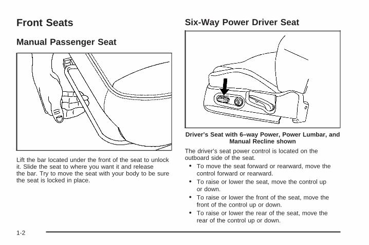
Manual Passenger Seat
Lift the bar located under the front of the seat to unlockit. Slide the seat to where you want it and releasethe bar. Try to move the seat with your body to be surethe seat is locked in place.
Six-Way Power Driver Seat
The driver’s seat power control is located on theoutboard side of the seat.• To move the seat forward or rearward, move the
control forward or rearward.• To raise or lower the seat, move the control up
or down.• To raise or lower the front of the seat, move the
front of the control up or down.• To raise or lower the rear of the seat, move the
rear of the control up or down.
Driver’s Seat with 6–way Power, Power Lumbar, andManual Recline shown
1-2
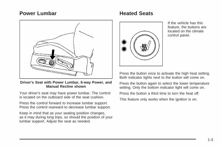
Power Lumbar
Your driver’s seat may have power lumbar. The controlis located on the outboard side of the seat cushion.
Press the control forward to increase lumbar support.Press the control rearward to decrease lumbar support.
Keep in mind that as your seating position changes,as it may during long trips, so should the position of yourlumbar support. Adjust the seat as needed.
Heated Seats
If the vehicle has thisfeature, the buttons arelocated on the climatecontrol panel.
Press the button once to activate the high heat setting.Both indicator lights next to the button will come on.
Press the button again to select the lower temperaturesetting. Only the bottom indicator light will come on.
Press the button a third time to turn the heat off.
This feature only works when the ignition is on.
Driver’s Seat with Power Lumbar, 6-way Power, andManual Recline shown
1-3

Reclining Seatbacks
Lift the lever located on the outboard side of the seat torelease the seatback, then move the seatback to thedesired position. Release the lever to lock the seatbackin place.
{CAUTION:
If the seatback is not locked, it could moveforward in a sudden stop or crash. That couldcause injury to the person sitting there. Alwayspush and pull on the seatback to be sure itis locked.
Pull up on the lever without pushing on the seatback,and the seatback will return to an upright position.
Driver’s Seat with Manual Recline, 6-way Power, andPower Lumbar shown
1-4

Do not have a seatback reclined if the vehicleis moving.
{CAUTION:
Sitting in a reclined position when your vehicleis in motion can be dangerous. Even if youbuckle up, your safety belts cannot do theirjob when you are reclined like this.
The shoulder belt cannot do its job because itwill not be against your body. Instead, it will bein front of you. In a crash, you could go into it,receiving neck or other injuries.
The lap belt cannot do its job either. In acrash, the belt could go up over yourabdomen. The belt forces would be there, notat your pelvic bones. This could cause seriousinternal injuries.
For proper protection when the vehicle is inmotion, have the seatback upright. Then sitwell back in the seat and wear your safetybelt properly.
1-5

Head Restraints
Pull up the head restraintto raise it. Press therelease button, located atthe base of the headrestraint, and pushthe head restraint downto lower it.
Adjust the head restraint so that the top of the restraintis closest to the top of the occupant’s head. Thisposition reduces the chance of a neck injury in a crash.
1-6

Passenger Folding Seatback
{CAUTION:
If you fold the seatback forward to carry longerobjects, such as skis, be sure any such cargois not near an airbag. In a crash, an inflatingairbag might force that object toward a person.This could cause severe injury or even death.Secure objects away from the area in which anairbag would inflate. For more information, seeWhere Are the Airbags? on page 1-55 andLoading Your Vehicle on page 4-33.
{CAUTION:
Things you put on this seatback can strikeand injure people in a sudden stop or turn,or in a crash. Remove or secure all itemsbefore driving.
If the vehicle has this feature, the front passenger seatcan be folded flat for more cargo space.
1-7

To fold the front passenger seatback flat, pull up on thelever located on back of the seat. Push the seatbackforward until it locks in place.
To return the seatback to the upright position, pull up onthe lever on the back of the seat. Push the seatbackup until it locks in place.
{CAUTION:
If the seatback is not locked, it could moveforward in a sudden stop or crash. That couldcause injury to the person sitting there. Alwayspush and pull on the seatback to be sure it islocked.
Push and pull on the seatback to make sure it is locked.
1-8

Rear Seats
Split Folding Rear SeatIf your vehicle has this feature, both sides of the rearseatback can be folded down. This gives direct accessto the trunk. Make sure the front seats are notreclined. If they are, the rear seatback(s) may not folddown all the way.
To lower the rear seatback,pull the tab located on theoutboard side of theseatback and fold theseatback forward.
{CAUTION:
If the seatback is not locked, it could moveforward in a sudden stop or crash. That couldcause injury to the person sitting there. Alwayspush and pull on the seatback to be sure itis locked.
To raise the rear seatback, lift the seatback up until itlatches. Push and pull on the seatback to be sureit is locked in position.
The seatbacks should be kept in the upright, lockedposition when they are not being used to extendthe cargo area.
1-9
Safety Belts
Safety Belts: They Are for EveryoneThis part of the manual tells you how to use safetybelts properly. It also tells you some things you shouldnot do with safety belts.
{CAUTION:
Do not let anyone ride where he or she cannotwear a safety belt properly. If you are in acrash and you are not wearing a safety belt,your injuries can be much worse. You can hitthings inside the vehicle or be ejected from it.You can be seriously injured or killed. In thesame crash, you might not be, if you arebuckled up. Always fasten your safety belt,and check that your passengers’ belts arefastened properly too.
{CAUTION:
It is extremely dangerous to ride in a cargoarea, inside or outside of a vehicle. In acollision, people riding in these areas are morelikely to be seriously injured or killed. Do notallow people to ride in any area of your vehiclethat is not equipped with seats and safety belts.Be sure everyone in your vehicle is in a seat andusing a safety belt properly.
Your vehicle has indicators to remind you and yourpassengers to buckle your safety belts. See Safety BeltReminder Light on page 3-38 and Passenger SafetyBelt Reminder Light on page 3-38.
1-10

In most states and in all Canadian provinces, the lawsays to wear safety belts. Here is why: They work.
You never know if you will be in a crash. If you do havea crash, you do not know if it will be a bad one.
A few crashes are mild, and some crashes can be soserious that even buckled up, a person would not survive.But most crashes are in between. In many of them,people who buckle up can survive and sometimes walkaway. Without belts they could have been badly hurtor killed.
After more than 30 years of safety belts in vehicles, thefacts are clear. In most crashes buckling up doesmatter...a lot!
Why Safety Belts WorkWhen you ride in or on anything, you go as fast asit goes.
Take the simplest vehicle. Suppose it is just a seaton wheels.
1-11

Put someone on it. Get it up to speed. Then stop the vehicle. The riderdoes not stop.
1-12
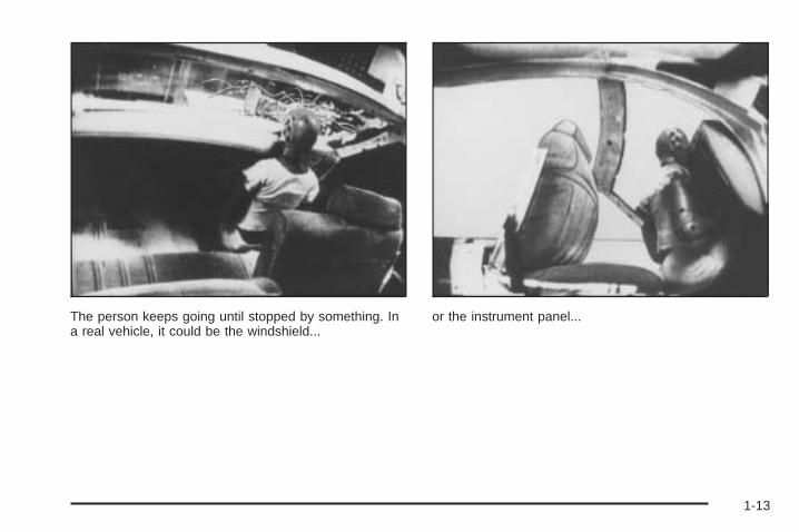
The person keeps going until stopped by something. Ina real vehicle, it could be the windshield...
or the instrument panel...
1-13

or the safety belts!
With safety belts, you slow down as the vehicle does.You get more time to stop. You stop over more distance,and your strongest bones take the forces. That is whysafety belts make such good sense.
Questions and Answers AboutSafety Belts
Q: Will I be trapped in the vehicle after an accidentif I am wearing a safety belt?
A: You could be — whether you are wearing a safetybelt or not. But you can unbuckle a safety belt,even if you are upside down. And your chance ofbeing conscious during and after an accident,so you can unbuckle and get out, is much greater ifyou are belted.
Q: If my vehicle has airbags, why should I have towear safety belts?
A: Airbags are in many vehicles today and will be inmost of them in the future. But they aresupplemental systems only; so they work withsafety belts — not instead of them. Every airbagsystem ever offered for sale has required the use ofsafety belts. Even if you are in a vehicle that hasairbags, you still have to buckle up to get the mostprotection. That is true not only in frontal collisions,but especially in side and other collisions.
1-14

Q: If I am a good driver, and I never drive far fromhome, why should I wear safety belts?
A: You may be an excellent driver, but if you are in anaccident — even one that is not your fault — youand your passengers can be hurt. Being a gooddriver does not protect you from things beyond yourcontrol, such as bad drivers.
Most accidents occur within 25 miles (40 km)of home. And the greatest number of seriousinjuries and deaths occur at speeds of less than40 mph (65 km/h).
Safety belts are for everyone.
How to Wear Safety Belts ProperlyThis part is only for people of adult size.
Be aware that there are special things to know aboutsafety belts and children. And there are differentrules for smaller children and babies. If a child will beriding in your vehicle, see Older Children on page 1-30or Infants and Young Children on page 1-33. Followthose rules for everyone’s protection.
First, you will want to know which restraint systems yourvehicle has.
We will start with the driver position.
1-15

Driver Position
Lap-Shoulder BeltThe driver has a lap-shoulder belt. Here is how to wearit properly.
1. Close and lock the door.
2. Adjust the seat so you can sit up straight. To seehow, see “Seats” in the Index.
3. Pick up the latch plate and pull the belt across you.Do not let it get twisted.
The shoulder belt may lock if you pull the beltacross you very quickly. If this happens, let the beltgo back slightly to unlock it. Then pull the beltacross you more slowly.
4. Push the latch plate into the buckle until it clicks.Pull up on the latch plate to make sure it is secure.If the belt is not long enough, see Safety BeltExtender on page 1-29.Make sure the release button on the buckle ispositioned so you would be able to unbuckle thesafety belt quickly if you ever had to.
5. Move the shoulder belt height adjuster to the heightthat is right for you. See Shoulder Belt HeightAdjustment on page 1-22.
1-16

6. To make the lap part tight, pull up on theshoulder belt.
The lap part of the belt should be worn low and snug onthe hips, just touching the thighs. In a crash, thisapplies force to the strong pelvic bones. And you wouldbe less likely to slide under the lap belt. If you slidunder it, the belt would apply force at your abdomen.This could cause serious or even fatal injuries. Theshoulder belt should go over the shoulder and acrossthe chest. These parts of the body are best able to takebelt restraining forces.
The safety belt locks if there is a sudden stop or crash,or if you pull the belt very quickly out of the retractor.
1-17

Q: What is wrong with this?
A: The shoulder belt is too loose. It will not give nearlyas much protection this way.
{CAUTION:
You can be seriously hurt if your shoulder beltis too loose. In a crash, you would moveforward too much, which could increase injury.The shoulder belt should fit against your body.
1-18

Q: What is wrong with this?
A: The belt is buckled in the wrong place.
{CAUTION:
You can be seriously injured if your belt isbuckled in the wrong place like this. In a crash,the belt would go up over your abdomen. Thebelt forces would be there, not at the pelvicbones. This could cause serious internalinjuries. Always buckle your belt into thebuckle nearest you.
1-19

Q: What is wrong with this?
A: The shoulder belt is worn under the arm. It shouldbe worn over the shoulder at all times.
{CAUTION:
You can be seriously injured if you wear theshoulder belt under your arm. In a crash, yourbody would move too far forward, which wouldincrease the chance of head and neck injury.Also, the belt would apply too much force tothe ribs, which are not as strong as shoulderbones. You could also severely injure internalorgans like your liver or spleen.
1-20

Q: What is wrong with this?
A: The belt is twisted across the body.
{CAUTION:
You can be seriously injured by a twisted belt.In a crash, you would not have the full width ofthe belt to spread impact forces. If a belt istwisted, make it straight so it can workproperly, or ask your dealer to fix it.
1-21
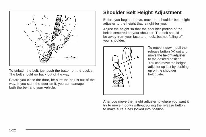
To unlatch the belt, just push the button on the buckle.The belt should go back out of the way.
Before you close the door, be sure the belt is out of theway. If you slam the door on it, you can damageboth the belt and your vehicle.
Shoulder Belt Height AdjustmentBefore you begin to drive, move the shoulder belt heightadjuster to the height that is right for you.
Adjust the height so that the shoulder portion of thebelt is centered on your shoulder. The belt shouldbe away from your face and neck, but not falling offyour shoulder.
To move it down, pull therelease button (A) out andmove the height adjusterto the desired position.You can move the heightadjuster up just by pushingup on the shoulderbelt guide.
After you move the height adjuster to where you want it,try to move it down without pulling the release buttonto make sure it has locked into position.
1-22

Safety Belt Use During PregnancySafety belts work for everyone, including pregnantwomen. Like all occupants, they are more likely to beseriously injured if they do not wear safety belts.
A pregnant woman should wear a lap-shoulder belt, andthe lap portion should be worn as low as possible,below the rounding, throughout the pregnancy.
The best way to protect the fetus is to protect themother. When a safety belt is worn properly, it is morelikely that the fetus will not be hurt in a crash. Forpregnant women, as for anyone, the key to makingsafety belts effective is wearing them properly.
Right Front Passenger PositionTo learn how to wear the right front passenger’s safetybelt properly, see Driver Position on page 1-16.
The right front passenger’s safety belt works the sameway as the driver’s safety belt — except for one thing. Ifyou ever pull the shoulder portion of the belt out all theway, you will engage the child restraint locking feature.If this happens, just let the belt go back all the way andstart again.
Rear Seat PassengersIt is very important for rear seat passengers to buckleup! Accident statistics show that unbelted people inthe rear seat are hurt more often in crashes than thosewho are wearing safety belts.
Rear passengers who are not safety belted can bethrown out of the vehicle in a crash. And they can strikeothers in the vehicle who are wearing safety belts.
1-23

Lap-Shoulder BeltAll rear seat positions have lap-shoulder belts. Here ishow to wear one properly.
1. Pick up the latch plate and pull the belt across you.Do not let it get twisted.The shoulder belt may lock if you pull the beltacross you very quickly. If this happens, let the beltgo back slightly to unlock it. Then pull the beltacross you more slowly.
2. Push the latch plate into the buckle until it clicks.Pull up on the latch plate to make sure it is secure.When the shoulder belt is pulled out all the way,it will lock. If it does, let it go back all the way andstart again.If the belt is not long enough, see Safety BeltExtender on page 1-29.Make sure the release button on the buckle ispositioned so you would be able to unbuckle thesafety belt quickly if you ever had to.
3. To make the lap part tight, pull up on theshoulder part.
1-24

The lap part of the belt should be worn low and snug onthe hips, just touching the thighs. In a crash, thisapplies force to the strong pelvic bones. And you wouldbe less likely to slide under the lap belt. If you slidunder it, the belt would apply force at your abdomen.This could cause serious or even fatal injuries. Theshoulder belt should go over the shoulder and acrossthe chest. These parts of the body are best able to takebelt restraining forces.
The safety belt locks if there is a sudden stop or a crash,or if you pull the belt very quickly out of the retractor.
{CAUTION:
You can be seriously hurt if your shoulder beltis too loose. In a crash, you would moveforward too much, which could increase injury.The shoulder belt should fit against your body.
To unlatch the belt, push the button on the buckle.
1-25

Rear Safety Belt Comfort GuidesRear shoulder belt comfort guides may provide addedsafety belt comfort for older children who have outgrownbooster seats and for some adults. When installed ona shoulder belt, the comfort guide positions the beltaway from the neck and head.
There is one guide for each outboard passengerposition in the rear seat. Here is how to install a comfortguide and use the safety belt:
1. Pull the elastic cord out from between the edge ofthe seatback and the interior body to remove theguide from its storage clip.
1-26

2. Slide the guide under and past the belt. The elasticcord must be under the belt. Then, place the guideover the belt, and insert the two edges of thebelt into the slots of the guide.
3. Be sure that the belt is not twisted and it lies flat.The elastic cord must be under the belt and theguide on top.
1-27
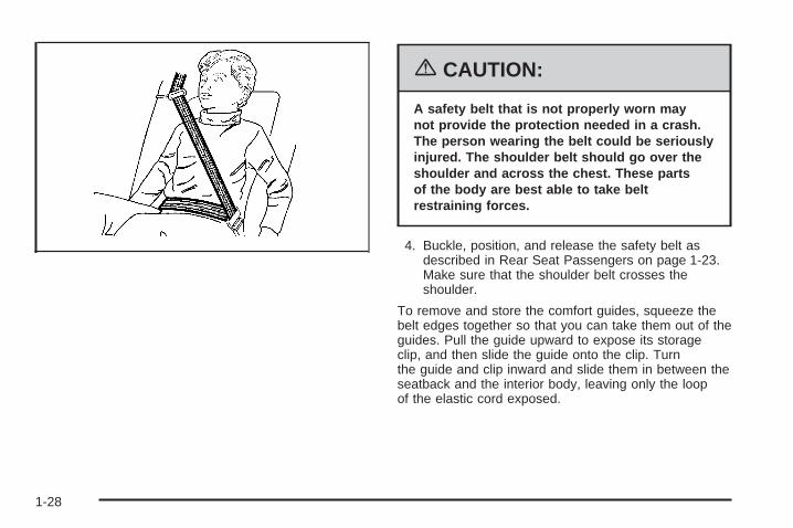
{CAUTION:
A safety belt that is not properly worn maynot provide the protection needed in a crash.The person wearing the belt could be seriouslyinjured. The shoulder belt should go over theshoulder and across the chest. These partsof the body are best able to take beltrestraining forces.
4. Buckle, position, and release the safety belt asdescribed in Rear Seat Passengers on page 1-23.Make sure that the shoulder belt crosses theshoulder.
To remove and store the comfort guides, squeeze thebelt edges together so that you can take them out of theguides. Pull the guide upward to expose its storageclip, and then slide the guide onto the clip. Turnthe guide and clip inward and slide them in between theseatback and the interior body, leaving only the loopof the elastic cord exposed.
1-28

Safety Belt PretensionersYour vehicle has safety belt pretensioners for the driverand right front passenger. Although you cannot seethem, they are located on the buckle end of the safetybelts. They help the safety belts reduce a person’sforward movement in a moderate to severe frontal andnear frontal crash.
Pretensioners work only once. If they activate in acrash, you will need to get new ones, and probably othernew parts for your safety belt system. See ReplacingRestraint System Parts After a Crash on page 1-67.
Safety Belt ExtenderIf the vehicle’s safety belt will fasten around you, youshould use it.
But if a safety belt is not long enough, your dealer willorder you an extender. It is free. When you go in toorder it, take the heaviest coat you will wear, sothe extender will be long enough for you. To help avoidpersonal injury, do not let someone else use it, anduse it only for the seat it is made to fit. The extender hasbeen designed for adults. Never use it for securingchild seats. To wear it, just attach it to the regular safetybelt. For more information, see the instruction sheetthat comes with the extender.
1-29

Child Restraints
Older Children
Older children who have outgrown booster seats shouldwear the vehicle’s safety belts.
Q: What is the proper way to wear safety belts?
A: An older child should wear a lap-shoulder belt andget the additional restraint a shoulder belt canprovide. The shoulder belt should not cross the faceor neck. The lap belt should fit snugly below thehips, just touching the top of the thighs. It shouldnever be worn over the abdomen, which couldcause severe or even fatal internal injuries ina crash.
Accident statistics show that children are safer if theyare restrained in the rear seat.
In a crash, children who are not buckled up can strikeother people who are buckled up, or can be thrownout of the vehicle. Older children need to use safetybelts properly.
1-30

{CAUTION:
Never do this.
Here two children are wearing the same belt.The belt can not properly spread the impactforces. In a crash, the two children can becrushed together and seriously injured. A beltmust be used by only one person at a time.
Q: What if a child is wearing a lap-shoulder belt,but the child is so small that the shoulder beltis very close to the child’s face or neck?
A: If the child is sitting in a seat next to a window,move the child toward the center of the vehicle.Also see Rear Safety Belt Comfort Guides onpage 1-26. If the child is sitting in the center rearseat passenger position, move the child toward thesafety belt buckle. In either case, be sure thatthe shoulder belt still is on the child’s shoulder, sothat in a crash the child’s upper body wouldhave the restraint the belts provide.
1-31

{CAUTION:
Never do this.
Here a child is sitting in a seat that has alap-shoulder belt, but the shoulder part isbehind the child. If the child wears the belt inthis way, in a crash the child might slide underthe belt. The belt’s force would then be appliedright on the child’s abdomen. That could causeserious or fatal injuries.
Wherever the child sits, the lap portion of the beltshould be worn low and snug on the hips, just touchingthe child’s thighs. This applies belt force to the child’spelvic bones in a crash.
1-32

Infants and Young ChildrenEveryone in a vehicle needs protection! This includesinfants and all other children. Neither the distancetraveled nor the age and size of the traveler changesthe need, for everyone, to use safety restraints. In fact,the law in every state in the United States and inevery Canadian province says children up to some agemust be restrained while in a vehicle.
Every time infants and young children ride in vehicles,they should have the protection provided by appropriaterestraints. Young children should not use the vehicle’sadult safety belts alone, unless there is no other choice.Instead, they need to use a child restraint.
{CAUTION:
People should never hold a baby in their armswhile riding in a vehicle. A baby does notweigh much — until a crash. During a crash ababy will become so heavy it is not possible tohold it. For example, in a crash at only 25 mph(40 km/h), a 12 lb (5.5 kg) baby will suddenlybecome a 240 lb (110 kg) force on a person’sarms. A baby should be secured in anappropriate restraint.
1-33
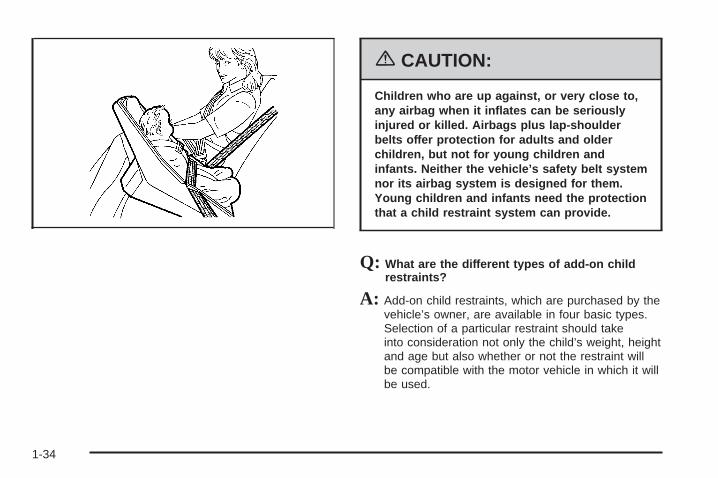
{CAUTION:
Children who are up against, or very close to,any airbag when it inflates can be seriouslyinjured or killed. Airbags plus lap-shoulderbelts offer protection for adults and olderchildren, but not for young children andinfants. Neither the vehicle’s safety belt systemnor its airbag system is designed for them.Young children and infants need the protectionthat a child restraint system can provide.
Q: What are the different types of add-on childrestraints?
A: Add-on child restraints, which are purchased by thevehicle’s owner, are available in four basic types.Selection of a particular restraint should takeinto consideration not only the child’s weight, heightand age but also whether or not the restraint willbe compatible with the motor vehicle in which it willbe used.
1-34

For most basic types of child restraints, there aremany different models available. When purchasing achild restraint, be sure it is designed to be usedin a motor vehicle. If it is, the restraint will have alabel saying that it meets federal motor vehiclesafety standards.
The restraint manufacturer’s instructions that comewith the restraint, state the weight and heightlimitations for a particular child restraint. In addition,there are many kinds of restraints available forchildren with special needs.
{CAUTION:
Newborn infants need complete support,including support for the head and neck. Thisis necessary because a newborn infant’s neckis weak and its head weighs so muchcompared with the rest of its body. In a crash,an infant in a rear-facing seat settles into therestraint, so the crash forces can bedistributed across the strongest part of aninfant’s body, the back and shoulders. Infantsalways should be secured in appropriate infantrestraints.
{CAUTION:
The body structure of a young child is quiteunlike that of an adult or older child, for whomthe safety belts are designed. A young child’ship bones are still so small that the vehicle’sregular safety belt may not remain low on thehip bones, as it should. Instead, it may settleup around the child’s abdomen. In a crash, thebelt would apply force on a body area that isunprotected by any bony structure. This alonecould cause serious or fatal injuries. Youngchildren always should be secured inappropriate child restraints.
1-35
Child Restraint Systems
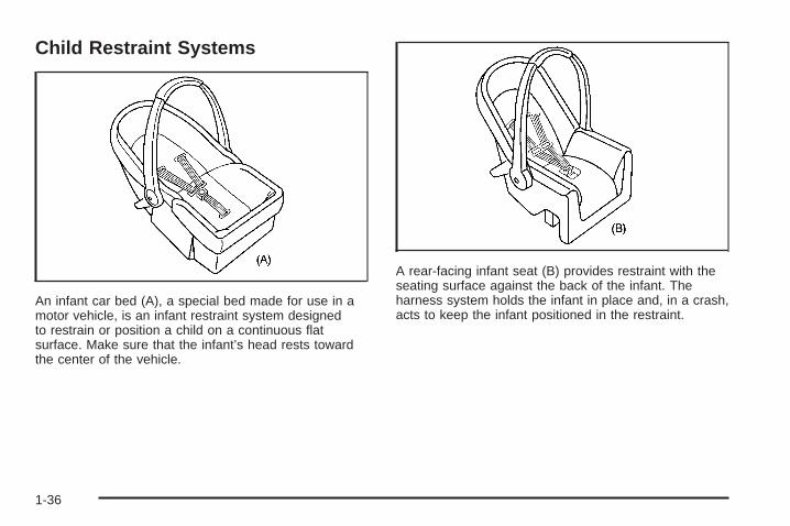
An infant car bed (A), a special bed made for use in amotor vehicle, is an infant restraint system designedto restrain or position a child on a continuous flatsurface. Make sure that the infant’s head rests towardthe center of the vehicle.
A rear-facing infant seat (B) provides restraint with theseating surface against the back of the infant. Theharness system holds the infant in place and, in a crash,acts to keep the infant positioned in the restraint.
1-36
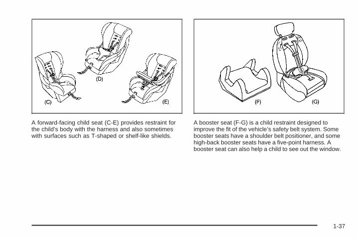
A forward-facing child seat (C-E) provides restraint forthe child’s body with the harness and also sometimeswith surfaces such as T-shaped or shelf-like shields.
A booster seat (F-G) is a child restraint designed toimprove the fit of the vehicle’s safety belt system. Somebooster seats have a shoulder belt positioner, and somehigh-back booster seats have a five-point harness. Abooster seat can also help a child to see out the window.
1-37
Q: How Should I Use a Child Restraint?
A: A child restraint system is any device designed foruse in a motor vehicle to restrain, seat, or positionchildren. A built-in child restraint system is apermanent part of the motor vehicle. An add-onchild restraint system is a portable one, whichis purchased by the vehicle’s owner. To help reduceinjuries, an add-on child restraint must be securedin the vehicle. With built-in or add-on childrestraints, the child has to be secured within thechild restraint.
When choosing an add-on child restraint, be surethe child restraint is designed to be used in avehicle. If it is, it will have a label saying that itmeets federal motor vehicle safety standards. Thenfollow the instructions for the restraint. You mayfind these instructions on the restraint itself or in abooklet, or both.
Securing an Add-on Child Restraint inthe Vehicle
{CAUTION:
A child can be seriously injured or killed in acrash if the child restraint is not properlysecured in the vehicle. Make sure the childrestraint is properly installed in the vehicleusing the vehicle’s safety belt or LATCHsystem, following the instructions that camewith that restraint, and also the instructions inthis manual.
To help reduce the chance of injury, the child restraintmust be secured in the vehicle. Child restraint systemsmust be secured in vehicle seats by lap belts or thelap belt portion of a lap-shoulder belt, or by the LATCHsystem. See Lower Anchors and Tethers for Children(LATCH) on page 1-41 for more information. A child canbe endangered in a crash if the child restraint is notproperly secured in the vehicle.
1-38

When securing an add-on child restraint, refer to theinstructions that come with the restraint which may be onthe restraint itself or in a booklet, or both, and to thismanual. The child restraint instructions are important, soif they are not available, obtain a replacement copyfrom the manufacturer.
Keep in mind that an unsecured child restraint canmove around in a collision or sudden stop and injurepeople in the vehicle. Be sure to properly secureany child restraint in your vehicle — even when no childis in it.
Securing the Child Within the ChildRestraintThere are several systems for securing the child withinthe child restraint. One system, the three-pointharness, has straps that come down over each of theinfant’s shoulders and buckle together at the crotch. Thefive-point harness system has two shoulder straps,two hip straps, and a crotch strap. A shield may take theplace of hip straps. A T-shaped shield has shoulderstraps that are attached to a flat pad which restslow against the child’s body. A shelf- or armrest-typeshield has straps that are attached to a wide, shelf-likeshield that swings up or to the side.
{CAUTION:
A child can be seriously injured or killed in acrash if the child is not properly secured in thechild restraint. Make sure the child is properlysecured, following the instructions that camewith that restraint.
Because there are different systems, it is important torefer to the instructions that come with the restraint.A child can be endangered in a crash if the child is notproperly secured in the child restraint.
1-39

Where to Put the RestraintAccident statistics show that children are safer if theyare restrained in the rear rather than the front seat. Werecommend that child restraints be secured in a rearseat, including an infant riding in a rear-facing infantseat, a child riding in a forward-facing child seat and anolder child riding in a booster seat.
Your vehicle has a rear seat that will accommodate arear-facing child restraint. A label on your sun visor says,“Never put a rear-facing child seat in the front.” Thisis because the risk to the rear-facing child is so great, ifthe airbag deploys.
{CAUTION:
A child in a rear-facing child restraint can beseriously injured or killed if the right frontpassenger’s airbag inflates. This is becausethe back of the rear-facing child restraintwould be very close to the inflating airbag.
CAUTION: (Continued)
CAUTION: (Continued)
Even though the passenger sensing system isdesigned to turn off the passenger’s frontalairbag if the system detects a rear-facing childrestraint, no system is fail-safe, and no onecan guarantee that an airbag will not deployunder some unusual circumstance, eventhough it is turned off. We recommend thatrear-facing child restraints be secured in therear seat, even if the airbag is off.
If you need to secure a forward-facing childrestraint in the right front seat, always movethe front passenger seat as far back as it willgo. It is better to secure the child restraint in arear seat.
Wherever you install a child restraint, be sure to securethe child restraint properly.
Keep in mind that an unsecured child restraint canmove around in a collision or sudden stop and injurepeople in the vehicle. Be sure to properly secureany child restraint in your vehicle — even when nochild is in it.
1-40
Lower Anchors and Tethers forChildren (LATCH)Your vehicle has the LATCH system. The LATCHsystem holds a child restraint during driving or in acrash. This system is designed to make installation of achild restraint easier. The LATCH system usesanchors in the vehicle and attachments on the childrestraint that are made for use with the LATCH system
Make sure that a LATCH-compatible child restraintis properly installed using the anchors, or use thevehicle’s safety belts to secure the restraint, followingthe instructions that came with that restraint, andalso the instructions in this manual. When installing achild restraint with a top tether, you must also use eitherthe lower anchors or the safety belts to properlysecure the child restraint. A child restraint must neverbe installed using only the top tether and anchor.
In order to use the LATCH system in your vehicle, youneed a child restraint equipped with LATCHattachments. The child restraint manufacturer willprovide you with instructions on how to use the childrestraint and its attachments. The following explains howto attach a child restraint with these attachments inyour vehicle.
Your vehicle has lower anchors and top tether anchors.Your child restraint may have lower attachments anda top tether.
Not all vehicle seating positions or child restraints havelower anchors and attachments or top tether anchorsand attachments.
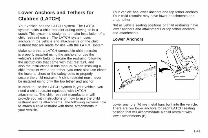
Lower Anchors
Lower anchors (A) are metal bars built into the vehicle.There are two lower anchors for each LATCH seatingposition that will accommodate a child restraint withlower attachments (B).
1-41

Top Tether Anchor
A top tether (A, C) anchors the top of the child restraintto the vehicle. A top tether anchor is built into thevehicle. The top tether attachment (B) on the childrestraint connects to the top tether anchor in the vehiclein order to reduce the forward movement and rotationof the child restraint during driving or in a crash.
Your child restraint may have a single tether (A) or adual tether (C). Either will have a single attachment (B)to secure the top tether to the anchor.
Some top tether-equipped child restraints are designedfor use with or without the top tether being attached.Others require the top tether always to be attached. InCanada, the law requires that forward-facing childrestraints have a top tether, and that the tether beattached. In the United States, some child restraints alsohave a top tether. Be sure to read and follow theinstructions for your child restraint.
If the child restraint does not have a top tether, one canbe obtained, in kit form, for many child restraints. Askthe child restraint manufacturer whether or not a kitis available.
1-42
Lower Anchor and Top Tether AnchorLocations
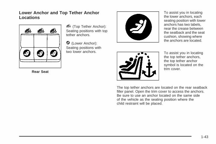
i (Top Tether Anchor):Seating positions with toptether anchors.
j (Lower Anchor):Seating positions withtwo lower anchors.
To assist you in locatingthe lower anchors, eachseating position with loweranchors has two labels,near the crease betweenthe seatback and the seatcushion, showing wherethe anchors are located.
To assist you in locatingthe top tether anchors,the top tether anchorsymbol is located on thetrim cover.
The top tether anchors are located on the rear seatbackfiller panel. Open the trim cover to access the anchors.Be sure to use an anchor located on the same sideof the vehicle as the seating position where thechild restraint will be placed.
Rear Seat
1-43

Do not secure a child restraint in the right frontpassenger’s position if a national or local law requiresthat the top tether be attached, or if the instructions thatcome with the child restraint say that the top tethermust be attached. There is no place to attach the toptether in this position.
Accident statistics show that children are safer if theyare restrained in the rear rather than the front seat. SeeWhere to Put the Restraint on page 1-40 for additionalinformation.
Securing a Child Restraint Designed forthe LATCH System
{CAUTION:
If a LATCH-type child restraint is not attachedto anchors, the restraint will not be able toprotect the child correctly. In a crash, the childcould be seriously injured or killed. Make surethat a LATCH-type child restraint is properlyinstalled using the anchors, or use thevehicle’s safety belts to secure the restraint,following the instructions that came withthat restraint, and also the instructions inthis manual.
1-44

{CAUTION:
Each top tether anchor and lower anchor in thevehicle is designed to hold only one childrestraint. Attaching more than one childrestraint to a single anchor could cause theanchor or attachment to come loose or evenbreak during a crash. A child or others couldbe injured if this happens. To help preventinjury to people and damage to your vehicle,attach only one child restraint per anchor.
1. Attach and tighten the lower attachments to thelower anchors. If the child restraint does not havelower attachments or the desired seating positiondoes not have lower anchors, secure the childrestraint with the top tether and the safety belts.Refer to your child restraint manufacturerinstructions and the instructions in this manual.
1.1. Find the lower anchors for the desiredseating position.
1.2. Put the child restraint on the seat.1.3. Attach and tighten the lower attachments on
the child restraint to the lower anchors.
2. If the child restraint manufacturer recommends thatthe top tether be attached, attach and tighten thetop tether to the top tether anchor, if equipped.Refer to the child restraint instructions andthe following steps:
2.1. Find the top tether anchor.2.2. Pull open the top tether anchor trim cover to
expose the anchor.2.3. Route, attach, and tighten the top tether
according to your child restraint instructionsand the following instructions:
If the position you areusing does not have ahead restraint and you areusing a single tether,route the tether overthe seatback.
If the position you areusing does not have ahead restraint and you areusing a dual tether,route the tether overthe seatback.
1-45
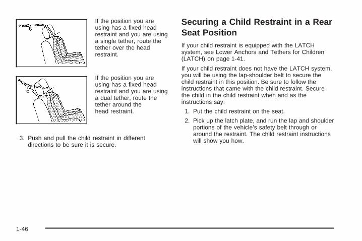
If the position you areusing has a fixed headrestraint and you are usinga single tether, route thetether over the headrestraint.
If the position you areusing has a fixed headrestraint and you are usinga dual tether, route thetether around thehead restraint.
3. Push and pull the child restraint in differentdirections to be sure it is secure.
Securing a Child Restraint in a RearSeat PositionIf your child restraint is equipped with the LATCHsystem, see Lower Anchors and Tethers for Children(LATCH) on page 1-41.
If your child restraint does not have the LATCH system,you will be using the lap-shoulder belt to secure thechild restraint in this position. Be sure to follow theinstructions that came with the child restraint. Securethe child in the child restraint when and as theinstructions say.
1. Put the child restraint on the seat.
2. Pick up the latch plate, and run the lap and shoulderportions of the vehicle’s safety belt through oraround the restraint. The child restraint instructionswill show you how.
1-46
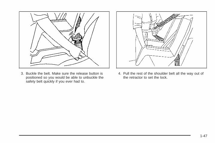
3. Buckle the belt. Make sure the release button ispositioned so you would be able to unbuckle thesafety belt quickly if you ever had to.
4. Pull the rest of the shoulder belt all the way out ofthe retractor to set the lock.
1-47

5. To tighten the belt, push down on the child restraint,pull the shoulder portion of the belt to tighten thelap portion of the belt and feed the shoulderbelt back into the retractor. If you are using aforward-facing child restraint, you may find it helpfulto use your knee to push down on the childrestraint as you tighten the belt.
6. If your child restraint manufacturer recommendsusing a top tether, attach and tighten the toptether to the top tether anchor. Refer to theinstructions that came with the child restraint andsee Lower Anchors and Tethers for Children(LATCH) on page 1-41.
7. Push and pull the child restraint in differentdirections to be sure it is secure.
To remove the child restraint, if the top tether is attachedto the top tether anchor, disconnect it. Unbuckle thevehicle’s safety belt and let it go back all the way. Thesafety belt will move freely again and be ready towork for an adult or larger child passenger.
Securing a Child Restraint in theRight Front Seat PositionYour vehicle has a right front passenger’s airbag. A rearseat is a safer place to secure a forward-facing childrestraint. See Where to Put the Restraint on page 1-40.
In addition, your vehicle has a passenger sensingsystem. The passenger sensing system is designed toturn off the right front passenger’s frontal airbagwhen an infant in a rear-facing infant seat or a smallchild in a forward-facing child restraint or booster seat isdetected. See Passenger Sensing System on page 1-61and Passenger Airbag Status Indicator on page 3-40for more information on this including importantsafety information.
A label on your sun visor says, “Never put a rear-facingchild seat in the front.” This is because the risk to therear-facing child is so great, if the airbag deploys.
1-48

{CAUTION:
A child in a rear-facing child restraint can beseriously injured or killed if the right frontpassenger’s airbag inflates. This is becausethe back of the rear-facing child restraintwould be very close to the inflating airbag.
Even though the passenger sensing system isdesigned to turn off the passenger’s frontalairbag if the system detects a rear-facing childrestraint, no system is fail-safe, and no onecan guarantee that an airbag will not deployunder some unusual circumstance, eventhough it is turned off. We recommend thatrear-facing child restraints be secured in therear seat, even if the airbag is off.
If you need to secure a forward-facing child restraint inthe right front seat position, move the seat as farback as it will go before securing the forward-facingchild restraint. See Manual Passenger Seat on page 1-2.
If your child restraint is equipped with the LATCHsystem, see Lower Anchors and Tethers for Children(LATCH) on page 1-41.
There is no top tether anchor at the right front seatingposition. Do not secure a child seat in this positionif a national or local law requires that the top tether beanchored or if the instructions that come with thechild restraint say that the top tether must be anchored.See Lower Anchors and Tethers for Children (LATCH)on page 1-41 if the child restraint has a top tether.
You will be using the lap-shoulder belt to secure thechild restraint in this position. Be sure to follow theinstructions that came with the child restraint. Securethe child in the child restraint when and as theinstructions say.
1. Your vehicle has a right front passenger’s frontalairbag. See Passenger Sensing System onpage 1-61. General Motors recommends thatrear-facing child restraints be secured in a rear seat,even if the airbag is off. If your child restraint isforward-facing, move the seat as far back as it willgo before securing the child restraint in thisseat. See Manual Passenger Seat on page 1-2.When the passenger sensing system has turned offthe right front passenger’s frontal airbag, the offindicator in the passenger airbag status indicatorshould light and stay lit when you turn the ignition toRUN or START. See Passenger Airbag StatusIndicator on page 3-40.
2. Put the child restraint on the seat.
1-49

3. Pick up the latch plate, and run the lap and shoulderportions of the vehicle’s safety belt through oraround the restraint. The child restraint instructionswill show you how.
4. Buckle the belt. Make sure the release button ispositioned so you would be able to unbuckle thesafety belt quickly if you ever had to.
5. Pull the rest of the shoulder belt all the way out ofthe retractor to set the lock.
1-50

6. To tighten the belt, push down on the child restraint,pull the shoulder portion of the belt to tighten thelap portion of the belt and feed the shoulderbelt back into the retractor. If you are using aforward-facing child restraint, you may find it helpfulto use your knee to push down on the childrestraint as you tighten the belt. You should not beable to pull more of the belt from the retractoronce the lock has been set.
7. Push and pull the child restraint in differentdirections to be sure it is secure.
8. If the airbag is off, the off indicator on the instrumentpanel will be lit and stay lit when the key is turnedto RUN or START.
If a child restraint has been installed and the onindicator is lit, turn the vehicle off. Remove the childrestraint from the vehicle and reinstall the child restraint.
If after reinstalling the child restraint and restartingthe vehicle, the on indicator is still lit, check to makesure that the vehicle’s seatback is not pressing the childrestraint into the seat cushion. If this happens, slightlyrecline the vehicle’s seatback and adjust the seatcushion if possible. Also make sure the child restraint isnot trapped under the vehicle head restraint. If thishappens, adjust the head restraint.
If the on indicator is still lit, secure the child in the childrestraint in a rear seat position in the vehicle andcheck with your dealer.
To remove the child restraint, just unbuckle the vehicle’ssafety belt and let it go back all the way. The safetybelt will move freely again and be ready to work for anadult or larger child passenger.
1-51
Airbag SystemYour vehicle has a frontal airbag for the driver and afrontal airbag for the right front passenger. Your vehiclemay also have roof-mounted side impact airbags.Roof-mounted side impact airbags are available for thedriver and the passenger seated directly behind thedriver and for the right front passenger and thepassenger seated directly behind that passenger.
If your vehicle has side impact airbags, the wordsAIR BAG will appear on the airbag covering on theceiling near the driver’s and right frontpassenger’s window.
Frontal airbags are designed to help reduce the risk ofinjury from the force of an inflating frontal airbag.But these airbags must inflate very quickly to do theirjob and comply with federal regulations.
Here are the most important things to know about theairbag system:
{CAUTION:
You can be severely injured or killed in a crashif you are not wearing your safety belt — evenif you have airbags. Wearing your safety beltduring a crash helps reduce your chance ofhitting things inside the vehicle or beingejected from it. Airbags are “supplementalrestraints” to the safety belts. All airbags aredesigned to work with safety belts but do notreplace them.
CAUTION: (Continued)
1-52
CAUTION: (Continued)
Frontal airbags for the driver and right frontpassenger are designed to deploy in moderateto severe frontal and near frontal crashes. Theyare not designed to inflate in rollover, rearcrashes, or in many side crashes. And, for someunrestrained occupants, frontal airbags mayprovide less protection in frontal crashes thanmore forceful airbags have provided in the past.
Roof-mounted side impact airbags are designedto inflate in moderate to severe crashes wheresomething hits the side of your vehicle. Theyare not designed to inflate in frontal, in rolloveror in rear crashes. Everyone in your vehicleshould wear a safety belt properly — whether ornot there is an airbag for that person.
{CAUTION:
Both frontal and side impact airbags inflatewith great force, faster than the blink of aneye. If you are too close to an inflating airbag,as you would be if you were leaning forward, itcould seriously injure you. Safety belts helpkeep you in position for airbag inflation beforeand during a crash. Always wear your safetybelt even with frontal airbags. The drivershould sit as far back as possible while stillmaintaining control of the vehicle. Occupantsshould not lean on or sleep against the door.
1-53

{CAUTION:
Anyone who is up against, or very close to,any airbag when it inflates can be seriouslyinjured or killed. Airbags plus lap-shoulderbelts offer the best protection for adults, butnot for young children and infants. Neither thevehicle’s safety belt system nor its airbagsystem is designed for them. Young childrenand infants need the protection that a childrestraint system can provide. Always securechildren properly in your vehicle. To read how,see Older Children on page 1-30 or Infants andYoung Children on page 1-33.
There is an airbagreadiness light onthe instrument panelcluster, which shows theairbag symbol.
The system checks the airbag electrical system formalfunctions. The light tells you if there is an electricalproblem. See Airbag Readiness Light on page 3-39for more information.
1-54

Where Are the Airbags?
The driver’s airbag is in the middle of thesteering wheel.
The right front passenger’s airbag is in the instrumentpanel on the passenger’s side.
1-55

The side impact airbag for the driver and the personseated directly behind the driver is in the ceiling abovethe side windows.
The side impact airbag for the right front passenger andthe person seated directly behind that passenger is inthe ceiling above the side windows.
1-56
{CAUTION:
If something is between an occupant and anairbag, the bag might not inflate properly or itmight force the object into that person causingsevere injury or even death. The path of aninflating airbag must be kept clear. Do not putanything between an occupant and an airbag,and do not attach or put anything on thesteering wheel hub or on or near any otherairbag covering. And, if your vehicle hasroof-mounted side impact airbags, neversecure anything to the roof of your vehicle byrouting the rope or tiedown through any dooror window opening. If you do, the path of aninflating side impact airbag will be blocked.The path of an inflating airbag must bekept clear.
When Should an Airbag Inflate?The driver’s and right front passenger’s frontal airbagsare designed to inflate in moderate to severe frontalor near-frontal crashes. But they are designed to inflateonly if the impact exceeds a predetermined deploymentthreshold. Deployment thresholds take into accounta variety of desired deployment and non-deploymentevents and are used to predict how severe a crashis likely to be in time for the airbags to inflate and helprestrain the occupants. Whether your frontal airbagswill or should deploy is not based on how fast yourvehicle is traveling. It depends largely on what you hit,the direction of the impact and how quickly yourvehicle slows down.
1-57
In addition, your vehicle has “dual-stage” frontal airbags,which adjust the restraint according to crash severity.Your vehicle is equipped with electronic frontal sensorswhich help the sensing system distinguish between amoderate frontal impact and a more severe frontalimpact. For moderate frontal impacts, these airbagsinflate at a level less than full deployment. Formore severe frontal impacts, full deployment occurs. Ifthe front of your vehicle goes straight into a wallthat does not move or deform, the threshold level forthe reduced deployment is about 12 to 16 mph(19 to 26 km/h), and the threshold level for a fulldeployment is about 18 to 24 mph (29 to 38.5 km/h).The threshold level can vary, however, with specificvehicle design, so that it can be somewhat aboveor below this range.
Frontal airbags may inflate at different crash speeds.For example:
• If the vehicle hits a stationary object, the airbagscould inflate at a different crash speed than if thevehicle hits a moving object.
• If the vehicle hits an object that deforms, theairbags could inflate at a different crash speed thanif the vehicle hits an object that does not deform.
• If the vehicle hits a narrow object (like a pole) theairbags could inflate at a different crash speedthan if the vehicle hits a wide object (like a wall).
• If the vehicle goes into an object at an angle theairbags could inflate at a different crash speedthan if the vehicle goes straight into the object.
Frontal airbags (driver and right front passenger) are notintended to inflate during vehicle rollovers, rearimpacts, or in many side impacts.
1-58

Your vehicle may or may not have side impact airbags.See Airbag System on page 1-52. Side impact airbagsare intended to inflate in moderate to severe sidecrashes. A side impact airbag will inflate if the crashseverity is above the system’s designed threshold level.The threshold level can vary with specific vehicle design.Side impact airbags are not intended to inflate in frontal ornear-frontal impacts, rollovers or rear impacts. A sideimpact airbag is intended to deploy on the side of thevehicle that is struck.In any particular crash, no one can say whether anairbag should have inflated simply because of thedamage to a vehicle or because of what the repair costswere. For frontal airbags, inflation is determined bywhat the vehicle hits, the angle of the impact, and howquickly the vehicle slows down. For side impactairbags, inflation is determined by the location andseverity of the impact.
What Makes an Airbag Inflate?In an impact of sufficient severity, the airbag sensingsystem detects that the vehicle is in a crash. Thesensing system triggers a release of gas from theinflator, which inflates the airbag. The inflator, airbag,and related hardware are all part of the airbag modulesinside the steering wheel and in the instrument panelin front of the right front passenger. For vehicleswith side impact airbags, there are also airbag modulesin the ceiling of the vehicle, near the side windows.
How Does an Airbag Restrain?In moderate to severe frontal or near frontal collisions,even belted occupants can contact the steering wheel orthe instrument panel. In moderate to severe sidecollisions, even belted occupants can contact the insideof the vehicle. The airbag supplements the protectionprovided by safety belts. Airbags distribute the force ofthe impact more evenly over the occupant’s upperbody, stopping the occupant more gradually. But thefrontal airbags would not help you in many typesof collisions, including rollovers, rear impacts, and manyside impacts, primarily because an occupant’s motionis not toward the airbag. Side impact airbags would nothelp you in many types of collisions, including manyfrontal or near frontal collisions, and rear impacts,primarily because an occupant’s motion is not towardthose airbags. Airbags should never be regardedas anything more than a supplement to safety belts, andthen only in moderate to severe frontal or near-frontalcollisions for the driver’s and right front passenger’sfrontal airbags, and only in moderate to severeside collisions for side impact airbags.
1-59
What Will You See After anAirbag Inflates?After a frontal airbag inflates, it quickly deflates, soquickly that some people may not even realizethe airbag inflated. Roof-mounted side impact airbagsdeflate more slowly and may still be at least partiallyinflated minutes after the vehicle comes to rest. Somecomponents of the airbag module — the steering wheelhub for the driver’s airbag, the instrument panel forthe right front passenger’s bag or the ceiling ofyour vehicle near the side windows — may be hot for ashort time. The parts of the bag that come intocontact with you may be warm, but not too hot to touch.There will be some smoke and dust coming from thevents in the deflated airbags. Airbag inflation doesnot prevent the driver from seeing out of the windshieldor being able to steer the vehicle, nor does it stoppeople from leaving the vehicle.
{CAUTION:
When an airbag inflates, there is dust in theair. This dust could cause breathing problemsfor people with a history of asthma or otherbreathing trouble. To avoid this, everyone inthe vehicle should get out as soon as it is safeto do so. If you have breathing problems butcannot get out of the vehicle after an airbaginflates, then get fresh air by opening awindow or a door. If you experience breathingproblems following an airbag deployment, youshould seek medical attention.
1-60

In many crashes severe enough to inflate an airbag,windshields are broken by vehicle deformation.Additional windshield breakage may also occur from theright front passenger airbag.
• Airbags are designed to inflate only once. After anairbag inflates, you will need some new parts foryour airbag system. If you do not get them,the airbag system will not be there to help protectyou in another crash. A new system will includeairbag modules and possibly other parts. Theservice manual for your vehicle covers the need toreplace other parts.
• Your vehicle is equipped with a crash sensing anddiagnostic module which records information aftera crash. See Vehicle Data Collection and EventData Recorders on page 7-9.
• Let only qualified technicians work on your airbagsystem. Improper service can mean that yourairbag system will not work properly. See yourdealer for service.
Passenger Sensing SystemYour vehicle has a passenger sensing system. Thepassenger airbag status indicator on the instrumentpanel will be visible when you turn your ignition key toRUN or START. The words ON and OFF or the symbolfor on and off, will be visible during the system check.If you use remote start to start your vehicle from adistance, if equipped, you may not see the systemcheck. When the system check is complete, either theword ON or the word OFF, or the symbol for on orthe symbol for off will be visible. See Passenger AirbagStatus Indicator on page 3-40.
The passenger sensing system will turn off the rightfront passenger’s frontal airbag under certain conditions.The driver’s airbag and the side airbags are not partof the passenger sensing system.
PassengerAirbag Status
Indicator – UnitedStates
PassengerAirbag Status
Indicator – Canada
1-61
The passenger sensing system works with sensors thatare part of the right front passenger’s seat. Thesensors are designed to detect the presence of aproperly-seated occupant and determine if thepassenger’s frontal airbag should be enabled (mayinflate) or not.
Accident statistics show that children are safer if they arerestrained in the rear rather than the front seat. GeneralMotors recommends that child restraints be secured in arear seat, including an infant riding in a rear-facing infantseat, a child riding in a forward-facing child seat, and anolder child riding in a booster seat.
Your vehicle has a rear seat that will accommodate arear-facing child restraint. A label on your sun visor says,“Never put a rear-facing child seat in the front.” Thisis because the risk to the rear-facing child is so great, ifthe airbag deploys.
{CAUTION:
A child in a rear-facing child restraint can beseriously injured or killed if the right frontpassenger’s airbag inflates. This is becausethe back of the rear-facing child restraintwould be very close to the inflating airbag.
Even though the passenger sensing system isdesigned to turn off the passenger’s frontalairbag if the system detects a rear-facing childrestraint, no system is fail-safe, and no onecan guarantee that an airbag will not deployunder some unusual circumstance, eventhough it is turned off. We recommend thatrear-facing child restraints be secured in therear seat, even if the airbag is off.
If you need to secure a forward-facing childrestraint in the right front seat, always movethe front passenger seat as far back as it willgo. It is better to secure the child restraint in arear seat.
1-62
The passenger sensing system is designed to turn offthe right front passenger’s frontal airbag if:
• the right front passenger seat is unoccupied
• the system determines that an infant is present in arear-facing infant seat
• the system determines that a small child is presentin a forward-facing child restraint
• the system determines that a small child is presentin a booster seat
• a right front passenger takes his/her weight off ofthe seat for a period of time
• the right front passenger seat is occupied by asmaller person, such as a child who has outgrownchild restraints
• or if there is a critical problem with the airbagsystem or the passenger sensing system.
When the passenger sensing system has turned off theright front passenger’s frontal airbag, the off indicatoron the instrument panel will light and stay lit to remindyou that the airbag is off.
If a child restraint has been installed and the onindicator is lit, turn the vehicle off. Remove the childrestraint from the vehicle and reinstall the child restraintfollowing the child restraint manufacturer’s directionsand refer to Securing a Child Restraint in the Right FrontSeat Position on page 1-48.
If after reinstalling the child restraint and restarting thevehicle, the on indicator is still lit, check to makesure that the vehicle’s seatback is not pressing the childrestraint into the seat cushion. If this happens, slightlyrecline the vehicle’s seatback and adjust the seatcushion if possible. Also make sure the child restraint isnot trapped under the vehicle head restraint. If thishappens, adjust the head restraint.
If the on indicator is still lit, secure the child in the childrestraint in a rear seat position in the vehicle andcheck with your dealer.
The passenger sensing system is designed to enable(may inflate) the right front passenger’s frontalairbag anytime the system senses that a person of adultsize is sitting properly in the right front passenger’sseat. When the passenger sensing system has allowedthe airbag to be enabled, the on indicator will lightand stay lit to remind you that the airbag is active.
For some children who have outgrown child restraintsand for very small adults, the passenger sensing systemmay or may not turn off the right front passenger’sfrontal airbag, depending upon the person’s seatingposture and body build. Everyone in your vehicle whohas outgrown child restraints should wear a safetybelt properly — whether or not there is an airbag forthat person.
1-63
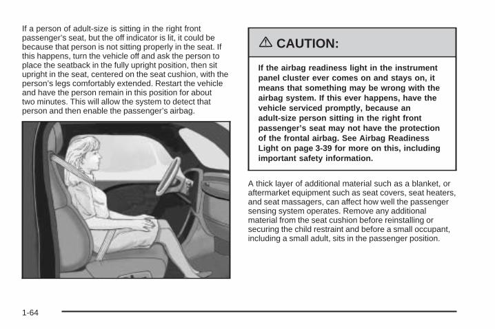
If a person of adult-size is sitting in the right frontpassenger’s seat, but the off indicator is lit, it could bebecause that person is not sitting properly in the seat. Ifthis happens, turn the vehicle off and ask the person toplace the seatback in the fully upright position, then situpright in the seat, centered on the seat cushion, with theperson’s legs comfortably extended. Restart the vehicleand have the person remain in this position for abouttwo minutes. This will allow the system to detect thatperson and then enable the passenger’s airbag.
{CAUTION:
If the airbag readiness light in the instrumentpanel cluster ever comes on and stays on, itmeans that something may be wrong with theairbag system. If this ever happens, have thevehicle serviced promptly, because anadult-size person sitting in the right frontpassenger’s seat may not have the protectionof the frontal airbag. See Airbag ReadinessLight on page 3-39 for more on this, includingimportant safety information.
A thick layer of additional material such as a blanket, oraftermarket equipment such as seat covers, seat heaters,and seat massagers, can affect how well the passengersensing system operates. Remove any additionalmaterial from the seat cushion before reinstalling orsecuring the child restraint and before a small occupant,including a small adult, sits in the passenger position.
1-64

You may want to consider not using seat covers or otheraftermarket equipment if your vehicle has the passengersensing system. See Adding Equipment to YourAirbag-Equipped Vehicle on page 1-66 for moreinformation about modifications that can affect how thesystem operates.
The passenger sensing system may suppress theairbag deployment when liquid is soaked into the seat. Ifthis happens, the off indicator in the passenger airbagstatus indicator and the airbag readiness light onthe instrument panel will be lit. The system shouldresume normal operation after the seat is allowed to dry.If the system operates incorrectly after the seat hasdried, have your dealer check the system.
{CAUTION:
Stowing of articles under the passenger’s seator between the passenger’s seat cushion andseatback may interfere with the properoperation of the passenger sensing system.
Servicing Your Airbag-EquippedVehicleAirbags affect how your vehicle should be serviced.There are parts of the airbag system in several placesaround your vehicle. You do not want the system toinflate while someone is working on your vehicle. Yourdealer and the service manual have informationabout servicing your vehicle and the airbag system. Topurchase a service manual, see Service PublicationsOrdering Information on page 7-14.
{CAUTION:
For up to 10 seconds after the ignition key isturned off and the battery is disconnected, anairbag can still inflate during improper service.You can be injured if you are close to anairbag when it inflates. Avoid yellowconnectors. They are probably part of theairbag system. Be sure to follow properservice procedures, and make sure the personperforming work for you is qualified to do so.
The airbag system does not need regular maintenance.
1-65
Adding Equipment to YourAirbag-Equipped Vehicle
Q: Is there anything I might add to the front orsides of the vehicle that could keep theairbags from working properly?
A: Yes. If you add things that change your vehicle’sframe, bumper system, front end or side sheetmetal or height, they may keep the airbag systemfrom working properly. Also, the airbag system maynot work properly if you relocate any of the airbagsensors. If you have any questions about this,you should contact Customer Service before youmodify your vehicle. The phone numbers andaddresses for Customer Assistance are in Step Twoof the Customer Satisfaction Procedure in thismanual. See Customer Satisfaction Procedure onpage 7-2.
Q: Because I have a disability, I have to get myvehicle modified. How can I find out whetherthis will affect my airbag system?
A: Changing or moving any parts of the front seats,safety belts, the airbag sensing and diagnosticmodule (located under the right front passenger’sseat), or the instrument panel can affect theoperation of the airbag system. If you havequestions, call Customer Assistance. The phonenumbers and addresses for Customer Assistanceare in Step Two of the Customer SatisfactionProcedure in this manual. See CustomerSatisfaction Procedure on page 7-2.
1-66

Restraint System Check
Checking the Restraint SystemsNow and then, make sure the safety belt reminder lightand all your belts, buckles, latch plates, retractorsand anchorages are working properly. Look for any otherloose or damaged safety belt system parts. If you seeanything that might keep a safety belt system from doingits job, have it repaired.
Torn or frayed safety belts may not protect you in acrash. They can rip apart under impact forces. If a beltis torn or frayed, get a new one right away.
Also look for any opened or broken airbag covers, andhave them repaired or replaced. (The airbag systemdoes not need regular maintenance.)
Notice: If you damage the covering for the driver’sor the right front passenger’s airbag, or the sideimpact airbag covering (if equipped) on the ceilingnear the side windows, the airbag may not workproperly. You may have to replace the airbagmodule in the steering wheel, both the airbagmodule and the instrument panel for the right frontpassenger’s airbag, or side impact airbag moduleand ceiling covering for roof-mounted side impactairbags (if equipped.) Do not open or break theairbag coverings.
Replacing Restraint System PartsAfter a Crash
{CAUTION:
A crash can damage the restraint systems inyour vehicle. A damaged restraint system maynot properly protect the person using it,resulting in serious injury or even death in acrash. To help make sure your restraintsystems are working properly after a crash,have them inspected and any necessaryreplacements made as soon as possible.
If you have had a crash, do you need new belts orLATCH system parts?
After a very minor collision, nothing may be necessary.But if the belts were stretched, as they would be if wornduring a more severe crash, then you need new parts.
1-67

If the LATCH system was being used during a moresevere crash, you may need new LATCH system parts.
If belts are cut or damaged, replace them. Collisiondamage also may mean you will need to have LATCHsystem, safety belt or seat parts repaired or replaced.New parts and repairs may be necessary even if the beltor LATCH system was not being used at the time ofthe collision.
If an airbag inflates, you will need to replace airbagsystem parts. See the part on the airbag system earlierin this section.
If the frontal airbags inflate, you will also need toreplace the driver’s and right front passenger’s safetybelt buckle assembly. Be sure to do so. Then thenew buckle assembly will be there to help protect you ina collision.
After a crash you may need to replace the driver andfront passenger’s safety belt buckle assemblies, even ifthe frontal airbags have not deployed. The driverand front passenger’s safety belt buckle assembliescontain the safety belt pretensioners. Have your safetybelt pretensioners checked if your vehicle has beenin a collision, or if your airbag readiness light stays onafter you start your vehicle or while you are driving. SeeAirbag Readiness Light on page 3-39.
1-68

Keys ...............................................................2-2Remote Keyless Entry System .........................2-3Remote Keyless Entry System Operation ...........2-4
Doors and Locks ............................................2-10Door Locks ..................................................2-10Power Door Locks ........................................2-11Delayed Locking ...........................................2-11Programmable Automatic Door Locks ..............2-12Rear Door Security Locks ..............................2-12Lockout Protection ........................................2-13Trunk ..........................................................2-13
Windows ........................................................2-15Power Windows ............................................2-16Sun Visors ...................................................2-17
Theft-Deterrent Systems ..................................2-17Content Theft-Deterrent .................................2-17PASS-Key® III ..............................................2-19PASS-Key® III Operation ...............................2-20
Starting and Operating Your Vehicle ................2-21New Vehicle Break-In ....................................2-21Ignition Positions ..........................................2-22Retained Accessory Power (RAP) ...................2-22Starting the Engine .......................................2-23Engine Coolant Heater ..................................2-24
Displacement on Demand™ (DoD™)(5.3L Engine) ............................................2-25
Automatic Transaxle Operation .......................2-25Parking Brake ..............................................2-30Shifting Into Park (P) .....................................2-31Shifting Out of Park (P) .................................2-32Parking Over Things That Burn .......................2-33Engine Exhaust ............................................2-33Running the Engine While Parked ...................2-34
Mirrors ...........................................................2-35Manual Rearview Mirror with OnStar® ..............2-35Automatic Dimming Rearview Mirror with
Compass and Temperature Display ..............2-35Outside Power Mirrors ...................................2-37Outside Convex Mirror ...................................2-38
OnStar ® System .............................................2-38Storage Areas ................................................2-40
Glove Box ...................................................2-40Cupholder(s) ................................................2-41Overhead Console ........................................2-42Front Seat Storage Net .................................2-42Center Console Storage Area .........................2-42Assist Handles .............................................2-42Convenience Net ..........................................2-43
Sunroof .........................................................2-43
Section 2 Features and Controls
2-1

Keys
{CAUTION:
Leaving children in a vehicle with the ignitionkey is dangerous for many reasons. Theycould operate the power windows or othercontrols or even make the vehicle move. Thechildren or others could be badly injured oreven killed. Do not leave the keys in a vehiclewith children.
2-2
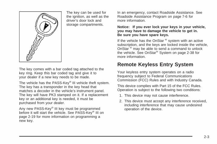
The key can be used forthe ignition, as well as thedriver’s door lock andstorage compartments.
The key comes with a bar coded tag attached to thekey ring. Keep this bar coded tag and give it toyour dealer if a new key needs to be made.
The vehicle has the PASS-Key® III vehicle theft system.The key has a transponder in the key head thatmatches a decoder in the vehicle’s instrument panel.The key will have PK3 stamped on it. If a replacementkey or an additional key is needed, it must bepurchased from your dealer.
Any new PASS-Key® III key must be programmedbefore it will start the vehicle. See PASS-Key® III onpage 2-19 for more information on programming anew key.
In an emergency, contact Roadside Assistance. SeeRoadside Assistance Program on page 7-6 formore information.
Notice: If you ever lock your keys in your vehicle,you may have to damage the vehicle to get in.Be sure you have spare keys.
If the vehicle has the OnStar ® system with an activesubscription, and the keys are locked inside the vehicle,OnStar ® may be able to send a command to unlockthe vehicle. See OnStar® System on page 2-38 formore information.
Remote Keyless Entry SystemYour keyless entry system operates on a radiofrequency subject to Federal CommunicationsCommission (FCC) Rules and with Industry Canada.
This device complies with Part 15 of the FCC Rules.Operation is subject to the following two conditions:
1. This device may not cause interference.
2. This device must accept any interference received,including interference that may cause undesiredoperation of the device.
2-3
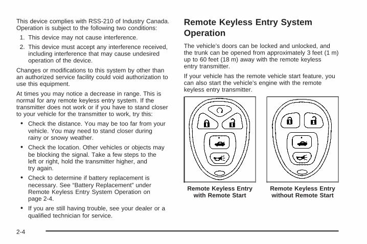
This device complies with RSS-210 of Industry Canada.Operation is subject to the following two conditions:
1. This device may not cause interference.
2. This device must accept any interference received,including interference that may cause undesiredoperation of the device.
Changes or modifications to this system by other thanan authorized service facility could void authorization touse this equipment.
At times you may notice a decrease in range. This isnormal for any remote keyless entry system. If thetransmitter does not work or if you have to stand closerto your vehicle for the transmitter to work, try this:
• Check the distance. You may be too far from yourvehicle. You may need to stand closer duringrainy or snowy weather.
• Check the location. Other vehicles or objects maybe blocking the signal. Take a few steps to theleft or right, hold the transmitter higher, andtry again.
• Check to determine if battery replacement isnecessary. See “Battery Replacement” underRemote Keyless Entry System Operation onpage 2-4.
• If you are still having trouble, see your dealer or aqualified technician for service.
Remote Keyless Entry SystemOperationThe vehicle’s doors can be locked and unlocked, andthe trunk can be opened from approximately 3 feet (1 m)up to 60 feet (18 m) away with the remote keylessentry transmitter.
If your vehicle has the remote vehicle start feature, youcan also start the vehicle’s engine with the remotekeyless entry transmitter.
Remote Keyless Entrywith Remote Start
Remote Keyless Entrywithout Remote Start
2-4

The following functions may be available with yourvehicle’s remote keyless entry system:
/ (Remote Vehicle Start): If your vehicle has thisfeature, the engine may be started from outsidethe vehicle using the remote keyless entry transmitter.See “Remote Vehicle Start” later in this section for moredetailed information.
Q (Lock): Press the lock button to lock all the doors.If enabled through the Driver Information Center(DIC), the parking lamps may flash once and the hornmay chirp once to indicate locking has occurred.See “REMOTE LOCKS FEEDBACK” under DIC Controlsand Displays (Base Level DIC) on page 3-52 or DICControls and Displays (Uplevel DIC with Trip Computer)on page 3-60 for programming information. Pressingthe lock button will arm the content theft-deterrentsystem. See Content Theft-Deterrent on page 2-17 formore information.
" (Unlock): Press the unlock button one time to unlockthe driver’s door. Press the unlock button again withinfive seconds to unlock the other doors. The interiorlamps will come on and stay on for 20 seconds or untilthe ignition is turned on. If enabled through the DIC,the parking lamps may flash once and the hornmay chirp once to indicate unlocking has occurred. See“REMOTE LOCKS FEEDBACK” under DIC Controlsand Displays (Base Level DIC) on page 3-52 orDIC Controls and Displays (Uplevel DIC with TripComputer) on page 3-60. Pressing the unlock button onthe remote keyless entry transmitter will disarm thecontent theft-deterrent system. See ContentTheft-Deterrent on page 2-17 for more details.
V (Trunk Release): Press this button to release thetrunk lid. The transaxle must be in PARK (P) for thisfeature to operate.
L (Panic Alarm): Press this button to activate thealarm. The ignition must be in OFF for the remote alarmto work. When the remote alarm button is pressedthe headlamps will flash and the horn will soundrepeatedly for two minutes. The alarm will turn off whenthe ignition is moved to RUN or the remote alarmbutton is pressed again.
2-5

Matching Transmitter(s) to Your VehicleEach remote keyless entry transmitter is coded toprevent another transmitter from unlocking your vehicle.If a transmitter is lost or stolen, a replacement canbe purchased through your GM dealer. Remember tobring any additional transmitters with you when yougo to your dealer. When the dealer matches thereplacement transmitter to your vehicle, any remainingtransmitters must also be matched. Once your dealerhas coded the new transmitter, the lost transmittercannot unlock your vehicle. The vehicle can have amaximum of four transmitters matched to it.
Battery ReplacementUnder normal use, the battery in the remote keylessentry transmitter should last about four years.
If the battery is weak the transmitter will not work withinits normal range. It is probably time to change thebattery if you have to be very close to the vehicle beforethe transmitter works.
The KEY FOB BATTERY LOW message, in thevehicle’s DIC, will display, if the remote keyless entrytransmitter battery is low.
Notice: When replacing the battery, use care not totouch any of the circuitry. Static from your bodytransferred to these surfaces may damage thetransmitter.
To replace the battery in the remote keyless entrytransmitter, do the following:
1. Insert a flat object with a thin edge into the notch,located below the panic alarm button, and separatethe bottom half from the top half of the transmitter.
2-6

2. Remove the old battery and replace it with the newone. Make sure the positive side (+) of the batteryfaces up. Use one three-volt, CR2032 battery,or equivalent type.
3. Put the two halves back together. Make sure thecover is on tight so water will not get inside thetransmitter.
4. Test the operation of the transmitter withthe vehicle.
Remote Vehicle StartYour vehicle may have a remote start feature. Thisfeature allows you to start the engine from outside thevehicle. It may also start the vehicle’s heating or airconditioning systems and rear window defogger. Whenthe remote start system is active, the climate controlsystem will heat or cool the inside of the vehicle basedon the outside temperature. The rear window defoggerwill be turned on by the climate control system when it isheating the inside of the vehicle. Normal operation ofthe system will return after the key is turned to RUN.
Laws in some communities may restrict the use ofremote starters. For example, some laws may require aperson using remote start to have the vehicle in viewwhen doing so. Check local regulations for anyrequirements on remote starting of vehicles.
Do not use the remote start feature if your vehicle is lowon fuel. Your vehicle may run out of fuel.
The remote start feature provides two separate startsper ignition cycle, each with 10 minutes of enginerunning time.
The remote start system needs to be reset after yourvehicle’s engine is started two times using thetransmitter’s remote start button. The remote startsystem is reset by inserting the vehicle’s key into theignition switch and turning to RUN. See IgnitionPositions on page 2-22 for information regarding theignition positions on your vehicle.
Your remote keyless entry transmitter with theremote start button provides an increased range ofoperation. You can start your vehicle from approximately492 feet (150 m) away. However, the range may beless while the vehicle is running, and as a resultyou may need to be closer to your vehicle to turn it offthan you were to turn it on.
There are other conditions which can affect theperformance of the transmitter, see Remote KeylessEntry System on page 2-3 for additional information.
2-7
/ (Remote Start): If your vehicle has the remotevehicle start feature, the keyless entry transmitter willhave a button with this symbol on it.
To start the vehicle using the remote start feature, dothe following:
1. Aim the transmitter at the vehicle.
2. Press and release the transmitter’s lock button,then immediately press and hold the transmitter’sremote start button for 4 seconds or until thevehicle’s turn signal lamps flash. The vehicle’s doorswill be locked.
3. When the vehicle starts, the parking lamps will turnon and remain on while the engine is running, andthe DIC will display REMOTE START ACTIVEPRESS HAZARD SWITCH TO CANCEL.The engine will shut off automatically after10 minutes, unless a time extension has been doneor the vehicle’s key is inserted into the ignitionswitch and turned to RUN.If you enter the vehicle after a remote start, and theengine is still running, insert the key into theignition switch and turn to RUN to drive the vehicle.
4. To manually shut off a remote start, do any of thefollowing. The parking lamps will turn off.
• Aim the remote keyless entry transmitter at thevehicle, and press the remote start button.
• Turn on the hazard warning flashers.
• Turn the ignition switch to RUN and then to OFF.
Your vehicle’s engine can be started two times using thetransmitter’s remote start feature. If only one remotestart procedure has been done, since last drivingthe vehicle, or resetting the remote start system, theengine may be started again remotely by following theremote start procedure a second time.
If the remote start procedure is used again beforethe first 10 minute time frame has ended, the first10 minutes will immediately expire and the second10 minute time frame will start.
2-8

The remote vehicle start feature will not operate if anyof the following occur:
• The remote start system is disabled throughthe DIC.
• The vehicle’s key is in the ignition.
• A door on the vehicle is open.
• The vehicle’s hood is open.
• The hazard warning flashers are on.
• There is an emission control system malfunction.
• The engine coolant temperature is too high.
• The oil pressure is low.
• Two remote vehicle starts have already beenprovided for that ignition cycle.
If a remote start is attempted and is unsuccessful, theDriver Information Center (DIC) will display REMOTESTART DISABLED.
Vehicles that have the remote vehicle start feature areshipped from the factory with the remote start systemenabled. The system may be enabled/disabled throughthe DIC. See “REMOTE START” under DIC Controlsand Displays (Base Level DIC) on page 3-52 orDIC Controls and Displays (Uplevel DIC with TripComputer) on page 3-60 for additional information.
Remote Start ReadyIf your vehicle does not have the remote vehicle startfeature, it may have the remote start ready feature. Thisfeature allows your dealer to add the manufacturer’sremote vehicle start feature.
If the keyless entry transmitter has a plus (+) symbol onthe back cover, your vehicle has the remote startready feature. You can lock or unlock your vehicle fromapproximately 492 feet (150 m) away.
See your dealer if you would like to add themanufacturer’s remote vehicle start feature toyour vehicle.
2-9

Doors and Locks
Door Locks
{CAUTION:
Unlocked doors can be dangerous.• Passengers — especially children — can
easily open the doors and fall out of amoving vehicle. When a door is locked, thehandle will not open it. You increase thechance of being thrown out of the vehiclein a crash if the doors are not locked. So,wear safety belts properly and lock thedoors whenever you drive.
• Young children who get into unlockedvehicles may be unable to get out. A childcan be overcome by extreme heat and cansuffer permanent injuries or even deathfrom heat stroke. Always lock your vehiclewhenever you leave it.
• Outsiders can easily enter through anunlocked door when you slow down orstop your vehicle. Locking your doors canhelp prevent this from happening.
There are several ways to lock and unlock the vehicle.
From the outside, use the key or remote keylessentry transmitter.
From the inside, use the manual or power door locks.
To manually lock or unlockthe doors from inside thevehicle, push down orpull up on the door lock pinlocated on the top ofeach door panel.
2-10
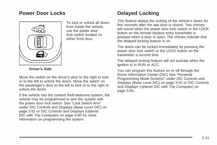
Power Door Locks
To lock or unlock all doorsfrom inside the vehicle,use the power doorlock switch located oneither front door.
Move the switch on the driver’s door to the right to lockor to the left to unlock the doors. Move the switch onthe passenger’s door to the left to lock or to the right tounlock the doors.
If the vehicle has the content theft-deterrent system, thevehicle may be programmed to arm the system withthe power door lock switch. See “Lock Switch Arm”under DIC Controls and Displays (Base Level DIC) onpage 3-52 or DIC Controls and Displays (UplevelDIC with Trip Computer) on page 3-60 for moreinformation on programming the system.
Delayed LockingThis feature delays the locking of the vehicle’s doors forfive seconds after the last door is closed. Two chimeswill sound when the power door lock switch or the LOCKbutton on the remote keyless entry transmitter ispressed when a door is open. The chimes indicate thatthe delayed locking feature is on.
The doors can be locked immediately by pressing thepower door lock switch or the LOCK button on thetransmitter a second time.
The delayed locking feature will not activate when theignition is in RUN or ACC.
You can program this feature on or off through theDriver Information Center (DIC) See “PersonalProgramming Mode Screens” under DIC Controls andDisplays (Base Level DIC) on page 3-52 or DIC Controlsand Displays (Uplevel DIC with Trip Computer) onpage 3-60.
Driver’s Side
2-11

Programmable AutomaticDoor LocksThe vehicle’s doors are programmed from the factory tolock when the shift lever is moved into a forwardgear, and to unlock when the shift lever is moved intoPARK (P).
If someone needs to get in or out of the vehicle afterthe doors have been locked, place the shift leverinto PARK (P). You may also unlock all doors using thepower door lock switch or unlock one door using theinside manual door lock.
To program other door locking/unlocking combinations,see “Personal Programming Mode Screens” underDIC Controls and Displays (Base Level DIC) onpage 3-52 or DIC Controls and Displays (Uplevel DICwith Trip Computer) on page 3-60.
Rear Door Security LocksYour vehicle may have rear door security locks. Theseprevent passengers from opening the rear doorsfrom the inside.
The rear door securitylocks are located on theinside edge of eachrear door. You mustopen the rear doors toaccess them.
To set the locks, do the following:
1. Insert the key into the security lock slot and turn itso the slot is in the horizontal position.
2. Close the door.
2-12
When you want to open a rear door when the securitylock is on, do the following:
1. Unlock the door using the remote keyless entrytransmitter, if equipped, the power door lockswitch, or by lifting the rear door manual lock.
2. Open the door from the outside.
To cancel the rear door security lock, do the following:
1. Unlock the door and open it from the outside.
2. Insert the key into the security lock slot and turn itso the slot is in the vertical position.
Lockout ProtectionThe lockout protection feature makes it more difficult tolock the key in the vehicle. If the driver’s door isopen while the key is in the ignition, the door cannot belocked with the power door lock switch.
This feature cannot guarantee that you will never belocked out of the vehicle. If the key is not left inthe ignition, or, if the manual door lock pin is used, thekey could still be locked inside the vehicle. Alwaysremember to take the key with you.
Trunk
{CAUTION:
It can be dangerous to drive with the trunk lidopen because carbon monoxide (CO) gas cancome into your vehicle. You cannot see orsmell CO. It can cause unconsciousness andeven death. If you must drive with the trunk lidopen or if electrical wiring or other cableconnections must pass through the sealbetween the body and the trunk lid:
• Make sure all other windows are shut.• Turn the fan on your heating or cooling
system to its highest speed and select thecontrol setting that will force outside airinto your vehicle. See Climate ControlSystem.
• If you have air outlets on or under theinstrument panel, open them all the way.
See Engine Exhaust on page 2-33.
To unlock and open the trunk from the outside, press thetrunk button on the remote keyless entry transmitter. SeeRemote Keyless Entry System Operation on page 2-4.
2-13

To open the trunk from the inside, use the power doorlock switch located on the driver’s or front passenger’sdoor. See “Remote Trunk Release” following.
The vehicle must be in PARK (P) in order for the trunkto open.
If the vehicle has lost power, you can open the trunk bylowering the rear seat and pulling the emergencytrunk release handle located in the trunk. See SplitFolding Rear Seat on page 1-9 and “Emergency TrunkRelease Handle” following.
Remote Trunk ReleaseThis feature is used to unlock the trunk from inside thevehicle using the power door lock switch.
Press and hold thedriver’s side powerdoor lock switch to theleft, or the passenger’sside power door lockswitch to the right tounlock the trunk.
Emergency Trunk Release Handle
Notice: Do not use the emergency trunk releasehandle as a tie-down or anchor point when securingitems in the trunk as it could damage the handle.The emergency trunk release handle is onlyintended to aid a person trapped in a latched trunk,enabling them to open the trunk from the inside.
There is a glow-in-the-dark emergency trunk releasehandle located on the trunk latch of the trunk lid.This handle will glow following exposure to light. If everneeded, pull the emergency trunk release handle toopen the trunk from the inside.Driver’s Side
2-14

Windows
{CAUTION:
Leaving children, helpless adults, or pets in avehicle with the windows closed is dangerous.They can be overcome by the extreme heatand suffer permanent injuries or even deathfrom heat stroke. Never leave a child, ahelpless adult, or a pet alone in a vehicle,especially with the windows closed in warm orhot weather.
2-15

Power Windows
Use the switches onthe driver’s door armrestto operate each ofthe windows.
Push the switch rearward or forward to open or closethe window. The top switches operate the front windows,and the bottom switches operate the rear windows.Each passenger door also has a switch that operatesthat window.
The power window switches only work if the ignition ison or in ACC, or while Retained Accessory Power (RAP)is active. See Retained Accessory Power (RAP) onpage 2-22 for more information.
Express-Down WindowThe driver’s window switch has an express-downfeature. This allows the window to open fully withouthaving to continuously hold the switch. Tap the switchrearward, and the driver’s window will open a smallamount. Press the switch fully rearward and release andthe window will go all the way down.
To stop the window while it is lowering, press the frontof the switch. To raise the window, press and holdthe front of the switch.
Window Lockout
o (Window Lockout): The driver’s window switchincludes a lockout feature located above the powerwindow switches on the driver’s door armrest. Move theswitch to the right to prevent the passengers sitting inthe rear from using their window switches. Thedriver can still control all the windows with the lockouton. Move the switch to the left to disengage thelockout feature.
2-16

Sun VisorsTo help block out glare, pull the sun visors down. Pullon the inside edges of the sun visors to swing them fromthe front windshield to the side window.
Visor Vanity MirrorRaise the cover on the top of the sun visor to exposethe vanity mirror. If the vehicle has lighted vanity mirrors,the lamps come on when the cover is opened.
Theft-Deterrent SystemsVehicle theft is big business, especially in some cities.Although your vehicle has a number of theft-deterrentfeatures, we know that nothing we put on it can make itimpossible to steal.
Content Theft-DeterrentThe vehicle has a content theft-deterrent alarm system.
A red light located on topof the instrument panel,toward the center ofthe vehicle and nearthe windshield, will flashslowly when the systemis armed.
The theft-deterrent alarm system needs to be activatedthrough the Driver’s Information Center (DIC). See “TheftDeterrent” under the Personal Programming ModeScreens in DIC Controls and Displays (Base Level DIC)on page 3-52 or DIC Controls and Displays (Uplevel DICwith Trip Computer) on page 3-60. While armed, thedoors will not unlock with the power door lock switch. Theremote alarm will sound if someone tampers with thetrunk or enters the vehicle without using the remotekeyless entry transmitter or key to unlock the doors. Thehorn will sound and the headlamps will flash for up totwo minutes. The system will also cut off the fuel supply,preventing the vehicle from being driven.
2-17

Arming with the Power Lock SwitchThe vehicle’s content theft-deterrent alarm system canbe activated when the key is removed from the ignitionand the power door lock switch of either the driver’s orfront passenger’s door is used to lock the vehicle. Thedoor needs to be in the open position when pressing thepower door lock switch. The alarm system will notactivate if the door is closed and the power door lockswitch is pressed. This system can be activated throughthe Driver’s Information Center (DIC). See “Lock SwitchArm” under the Personal Programming Mode Screens inDIC Controls and Displays (Base Level DIC) onpage 3-52 or DIC Controls and Displays (Uplevel DICwith Trip Computer) on page 3-60.
When the doors are locked using the power door lockswitch of either front door, the red light, on top of theinstrument panel will start flashing indicating that thesystem is arming. After all the doors are closed there willbe a time delay and then the red light will begin to flash ata very slow rate indicating the system is armed.
Arming with the Remote KeylessEntry TransmitterThe alarm system will arm when the remote keylessentry transmitter is used to lock the doors after the keyis removed from the ignition. The red light will comeon to indicate that the system is arming. After all doorsare closed and locked, and after a time delay, thered light will begin flashing at a very slow rate to showthe system is armed.
Arming ConfirmationA red light located on top of the instrument panel,towards the center of the vehicle and near thewindshield, will flash slowly to confirm when thesystem is armed.
2-18

Disarming with the Remote KeylessEntry TransmitterThe alarm system will disarm when the remote keylessentry transmitter is used to unlock the doors. Thered light will go out to show that the system is disarmed.
Disarming with Your KeyThe alarm system will disarm when the key is used tounlock the doors. The red light will stop flashingwhen the system is disarmed. If you would like the keyto disarm the alarm system, see “Personal ProgrammingMode Screens” under DIC Controls and Displays(Base Level DIC) on page 3-52 or DIC Controls andDisplays (Uplevel DIC with Trip Computer) on page 3-60for more information.
PASS-Key ® IIIYour PASS-Key® III system operates on a radiofrequency subject to Federal CommunicationsCommission (FCC) Rules and with Industry Canada.
This device complies with Part 15 of the FCC Rules.Operation is subject to the following two conditions:
1. This device may not cause harmful interference.
2. This device must accept any interference received,including interference that may cause undesiredoperation.
This device complies with RSS-210 of Industry Canada.Operation is subject to the following two conditions:
1. This device may not cause interference.
2. This device must accept any interference received,including interference that may cause undesiredoperation of the device.
Changes or modifications to this system by other thanan authorized service facility could void authorization touse this equipment.
PASS-Key® III uses a radio frequency transponder inthe key that matches a decoder in your vehicle.
2-19

PASS-Key ® III Operation
The vehicle is equippedwith PASS-Key® III(Personalized AutomotiveSecurity System)theft-deterrent system.PASS-Key® III is a passivetheft-deterrent system.This means nothing specialneeds to be done to armor disarm the system.It works when the key isinserted or removedfrom the ignition.
PASS-Key® III uses a transponder in the ignition keythat matches a decoder in the vehicle.
When the PASS-Key® III system senses that the wrongkey has been inserted into the ignition, it shuts downthe vehicle’s starter and fuel systems. The starter will notwork and fuel will stop flowing to the engine. Ifsomeone tries to start the vehicle again with the wrongkey, the vehicle will not start. Anyone using atrial-and-error method to start the vehicle will bediscouraged to do so because of the high number ofelectrical key codes.
When trying to start the vehicle, if the engine does notstart and the STARTING DISABLED DUE TO THEFTSYSTEM warning message on the Driver InformationCenter (DIC) comes on, the key may have a damagedtransponder. Turn the ignition off and try again.
If the engine still does not start, and the key appears tobe undamaged, try another ignition key. At this time,you may also want to check the fuse. See Fusesand Circuit Breakers on page 5-112. If the engine stilldoes not start with the other key, the vehicle needsservice. If the vehicle does start, the first key may befaulty. See your dealer who can service thePASS-Key® III to have a new key made. In anemergency, contact Roadside Assistance. See RoadsideAssistance Program on page 7-6 for more information.
It is possible for the PASS-Key® III decoder to acceptthe transponder value of a new or replacement key. Upto 10 keys may be programmed for the vehicle. If allthe programmed keys are lost or do not operate,see your GM dealer or a locksmith who can servicePASS-Key® III to have keys made and programmed tothe system.
Canadian Owners: If all the keys are lost or damaged,only a GM dealer can service PASS-Key® III to havenew keys made and programmed to the system.
2-20

The following procedure is for programming a new orreplacement key when you have at least one alreadyprogrammed key. To program the new key do thefollowing:
1. Verify that the new key has PK3 stamped on it.2. Insert the master key in the ignition and start
the engine. If the engine will not start, see yourdealer for service.
3. After the engine has started, turn the key to OFF,and remove the key.
4. Insert the key to be programmed and turn it to RUNwithin five seconds of removing the original key.
5. The STARTING DISABLED DUE TO THEFTSYSTEM warning message on the DIC will turn off,once the key has been programmed. It may not beapparent that the SERVICE THEFT SYSTEMwarning message went on due to how quickly the keyis programmed.
6. Repeat Steps 1 through 5 if additional keys are tobe programmed.
If the STARTING DISABLED DUE TO THEFT SYSTEMwarning message appears and stays on the DIC while thevehicle is being driven, the engine will be able to berestarted if it is turned off. Your PASS-Key® III system,however, is not working properly and must be serviced byyour dealer. The vehicle is not protected by thePASS-Key® III system at this time. If the PASS-Key® IIIkey is lost or stolen, see your dealer or a locksmith whocan service PASS-Key® III to have a new key made.
Starting and Operating YourVehicle
New Vehicle Break-InNotice: Your vehicle does not need an elaboratebreak-in. But it will perform better in the long run ifyou follow these guidelines:
• Do not drive at any one constant speed, fast orslow, for the first 500 miles (805 km). Do notmake full-throttle starts. Avoid downshifting tobrake, or slow, the vehicle.
• Avoid making hard stops for the first 200 miles(322 km) or so. During this time your new brakelinings are not yet broken in. Hard stops with newlinings can mean premature wear and earlierreplacement. Follow this breaking-in guidelineevery time you get new brake linings.
• Do not tow a trailer during break-in. See Towing aTrailer on page 4-40 for the trailer towingcapabilities of your vehicle and moreinformation.
Following break-in, engine speed and load can begradually increased.
2-21
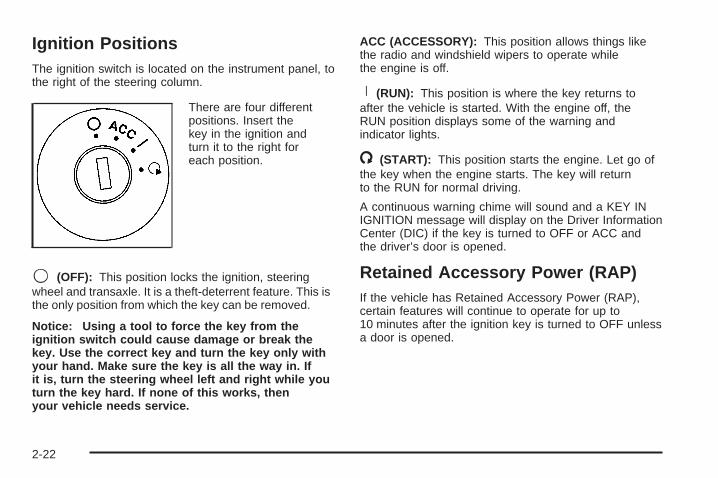
Ignition PositionsThe ignition switch is located on the instrument panel, tothe right of the steering column.
There are four differentpositions. Insert thekey in the ignition andturn it to the right foreach position.
9 (OFF): This position locks the ignition, steeringwheel and transaxle. It is a theft-deterrent feature. This isthe only position from which the key can be removed.
Notice: Using a tool to force the key from theignition switch could cause damage or break thekey. Use the correct key and turn the key only withyour hand. Make sure the key is all the way in. Ifit is, turn the steering wheel left and right while youturn the key hard. If none of this works, thenyour vehicle needs service.
ACC (ACCESSORY): This position allows things likethe radio and windshield wipers to operate whilethe engine is off.
R (RUN): This position is where the key returns toafter the vehicle is started. With the engine off, theRUN position displays some of the warning andindicator lights.
/ (START): This position starts the engine. Let go ofthe key when the engine starts. The key will returnto the RUN for normal driving.
A continuous warning chime will sound and a KEY INIGNITION message will display on the Driver InformationCenter (DIC) if the key is turned to OFF or ACC andthe driver’s door is opened.
Retained Accessory Power (RAP)If the vehicle has Retained Accessory Power (RAP),certain features will continue to operate for up to10 minutes after the ignition key is turned to OFF unlessa door is opened.
2-22

Starting the EngineMove your shift lever to PARK (P) or NEUTRAL (N).The engine will not start in any other position — that isa safety feature. To restart when you are alreadymoving, use NEUTRAL (N) only.
Notice: Shifting into PARK (P) with the vehiclemoving could damage the transaxle. Shift intoPARK (P) only when your vehicle is stopped.
1. With your foot off the accelerator pedal, turn theignition key to START. When the engine starts,let go of the key. The idle speed will go down as theengine gets warm.
Notice: Holding your key in START for longer than15 seconds at a time will cause your battery tobe drained much sooner. And the excessive heatcan damage your starter motor. Wait about15 seconds between each try to help avoid drainingyour battery or damaging your starter.
2. If the engine does not start within 10 seconds, holdyour key in START for about 10 seconds at a timeuntil the engine starts. Wait about 15 secondsbetween each try.
When your engine has run for about 10 seconds towarm up, your vehicle is ready to be driven. Donot race your engine when it is cold.If the weather is below freezing (32°F or 0°C), letthe engine run for a few minutes to warm up.
3. If your engine still will not start, or starts but thenstops, it could be flooded with too much gasoline.Try pushing your accelerator pedal all the way to thefloor and holding it there as you hold the key inSTART for about three seconds. If the vehicle startsbriefly but then stops again, do the samething. This time keep the pedal down for five orsix seconds to clear the extra gasoline fromthe engine. After waiting about 15 seconds, repeatthe normal starting procedure.
Notice: Your engine is designed to work with theelectronics in your vehicle. If you add electricalparts or accessories, you could change the way theengine operates. Before adding electrical equipment,check with your dealer. If you do not, your enginemight not perform properly. Any resulting damagewould not be covered by your vehicle’s warranty.
2-23

Engine Coolant HeaterThe vehicle may be equipped with an engine coolantheater. In very cold weather, 0°F (−18°C) or colder, theengine coolant heater can help. The vehicle will starteasier and get better fuel economy during enginewarm-up. Usually, the coolant heater should be pluggedin a minimum of four hours prior to starting thevehicle. At temperatures above 32°F (0°C), use of thecoolant heater is not required. Your vehicle mayalso have an internal thermostat in the plug end of thecord. This will prevent operation of the engine coolantheater when the temperature is at or above 0°F (−18°C)as noted on the cord.
To Use the Engine Coolant Heater1. Turn off the engine.
2. Open the hood and unwrap the electrical cord. Thecord is located above the engine air cleaner/filter.See Engine Compartment Overview on page 5-12for more information on location.
3. Plug the cord into a normal, grounded 110-voltAC outlet.
{CAUTION:
Plugging the cord into an ungrounded outletcould cause an electrical shock. Also, thewrong kind of extension cord could overheatand cause a fire. You could be seriouslyinjured. Plug the cord into a properly groundedthree-prong 110-volt AC outlet. If the cord willnot reach, use a heavy-duty three-prongextension cord rated for at least 15 amps.
4. Before starting the engine, be sure to unplug andstore the cord as it was before, making sure tokeep it away from moving engine parts. If this is notdone, the cord could be damaged.
How long should the coolant heater be kept plugged in?The answer depends on the outside temperature, thekind of oil that is in the vehicle, and some other things.Instead of trying to list everything here, we ask thatyou contact your dealer in the area where the vehicle willbe parked. The dealer can give you the best advicefor that particular area.
2-24
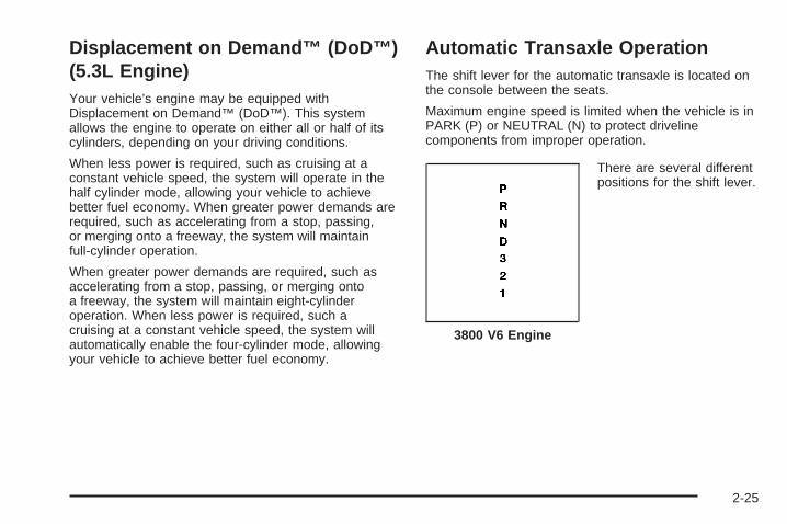
Displacement on Demand™ (DoD™)(5.3L Engine)Your vehicle’s engine may be equipped withDisplacement on Demand™ (DoD™). This systemallows the engine to operate on either all or half of itscylinders, depending on your driving conditions.
When less power is required, such as cruising at aconstant vehicle speed, the system will operate in thehalf cylinder mode, allowing your vehicle to achievebetter fuel economy. When greater power demands arerequired, such as accelerating from a stop, passing,or merging onto a freeway, the system will maintainfull-cylinder operation.
When greater power demands are required, such asaccelerating from a stop, passing, or merging ontoa freeway, the system will maintain eight-cylinderoperation. When less power is required, such acruising at a constant vehicle speed, the system willautomatically enable the four-cylinder mode, allowingyour vehicle to achieve better fuel economy.
Automatic Transaxle OperationThe shift lever for the automatic transaxle is located onthe console between the seats.
Maximum engine speed is limited when the vehicle is inPARK (P) or NEUTRAL (N) to protect drivelinecomponents from improper operation.
There are several differentpositions for the shift lever.
3800 V6 Engine
2-25
PARK (P): This position locks the front wheels. It is thebest position to use when the engine is startedbecause the vehicle cannot move easily.
{CAUTION:
It is dangerous to get out of your vehicle if theshift lever is not fully in PARK (P) with theparking brake firmly set. Your vehicle can roll.
Do not leave your vehicle when the engine isrunning unless you have to. If you have left theengine running, the vehicle can movesuddenly. You or others could be injured. Tobe sure your vehicle will not move, even whenyou are on fairly level ground, always set yourparking brake and move the shift lever toPARK (P). See Shifting Into Park (P) onpage 2-31. If you are pulling a trailer, seeTowing a Trailer on page 4-40.
Make sure the shift lever is fully in PARK (P) beforestarting the engine. The vehicle has an automatictransaxle shift lock control system.
The regular brakes must be fully applied and the shiftcontrol button, located on the front of the shift lever,must be pressed before the vehicle can be shifted fromPARK (P) when the ignition is in RUN. If the vehiclecannot be shifted out of PARK (P), ease pressure on theshift lever by pushing it all the way into PARK (P)while keeping the brake pedal pushed down. Releasethe shift lever button. Then move the shift lever outof PARK (P), being sure to press the shift lever button.See Shifting Out of Park (P) on page 2-32.
REVERSE (R): Use this gear to back up.
Notice: Shifting to REVERSE (R) while your vehicleis moving forward could damage the transaxle. Therepairs would not be covered by your warranty. Shiftto REVERSE (R) only after your vehicle is stopped.
To rock the vehicle back and forth to get out of snow, iceor sand without damaging the transaxle, see If YourVehicle is Stuck in Sand, Mud, Ice or Snow onpage 4-32.
NEUTRAL (N): In this position, the engine does notconnect with the wheels. To restart when the vehicle isalready moving, use NEUTRAL (N) only. Also, useNEUTRAL (N) when the vehicle is being towed.
2-26

{CAUTION:
Shifting into a drive gear while your engine isrunning at high speed is dangerous. Unlessyour foot is firmly on the brake pedal, yourvehicle could move very rapidly. You couldlose control and hit people or objects. Do notshift into a drive gear while your engine isrunning at high speed.
Notice: Shifting out of PARK (P) or NEUTRAL (N)while the engine is running at high speed maydamage the transaxle. The repairs would not becovered by your warranty. Be sure the engine is notrunning at high speeds when shifting your vehicle.
AUTOMATIC OVERDRIVE (D): This position is fornormal driving. If the vehicle needs more powerfor passing, and it is:
• Going less than 35 mph (55 km/h), push theaccelerator pedal about halfway down.
• Going about 35 mph (55 km/h) or more, push theaccelerator pedal all the way down.
The vehicle will shift down to the next gear and havemore power.
Notice: If your vehicle seems to start up ratherslowly or not shift gears when you go faster, andyou continue to drive your vehicle that way, youcould damage the transaxle. Have your vehicleserviced right away. You can drive in SECOND (2)when you are driving less than 35 mph (55 km/h) andAUTOMATIC OVERDRIVE (D) for higher speedsuntil then.
THIRD (3): This position is also used for normal driving,but it offers more power and lower fuel economy thanAUTOMATIC OVERDRIVE (D).
Here are some times THIRD (3) could be used insteadof AUTOMATIC OVERDRIVE (D):
• When driving on hilly, winding roads.
• When towing a trailer, so there is less shiftingbetween gears.
• When going down a steep hill.
• When driving in non-highway scenarios (i.e. citystreets, etc.).
2-27
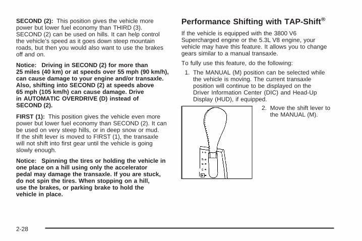
SECOND (2): This position gives the vehicle morepower but lower fuel economy than THIRD (3).SECOND (2) can be used on hills. It can help controlthe vehicle’s speed as it goes down steep mountainroads, but then you would also want to use the brakesoff and on.
Notice: Driving in SECOND (2) for more than25 miles (40 km) or at speeds over 55 mph (90 km/h),can cause damage to your engine and/or transaxle.Also, shifting into SECOND (2) at speeds above65 mph (105 km/h) can cause damage. Drivein AUTOMATIC OVERDRIVE (D) instead ofSECOND (2).
FIRST (1): This position gives the vehicle even morepower but lower fuel economy than SECOND (2). It canbe used on very steep hills, or in deep snow or mud.If the shift lever is moved to FIRST (1), the transaxlewill not shift into first gear until the vehicle is goingslowly enough.
Notice: Spinning the tires or holding the vehicle inone place on a hill using only the acceleratorpedal may damage the transaxle. If you are stuck,do not spin the tires. When stopping on a hill,use the brakes, or parking brake to hold thevehicle in place.
Performance Shifting with TAP-Shift ®
If the vehicle is equipped with the 3800 V6Supercharged engine or the 5.3L V8 engine, yourvehicle may have this feature. It allows you to changegears similar to a manual transaxle.
To fully use this feature, do the following:
1. The MANUAL (M) position can be selected whilethe vehicle is moving. The current transaxleposition will continue to be displayed on theDriver Information Center (DIC) and Head-UpDisplay (HUD), if equipped.
2. Move the shift lever tothe MANUAL (M).
2-28

3. The paddles arelocated on the steeringwheel. They areused to up-shift ordown-shift thetransaxle.
4. Push either paddle once to up-shift to the nextgear. Pull either paddle once to down-shift tothe next gear.The vehicle will begin moving in first gear uponacceleration. For better control in icy or slipperyconditions, the vehicle may start out in SECOND (2),rather than FIRST (1). This will only occur if youhave “tapped up” to second gear.
The up-shift light on theinstrument panel cluster, orthe up-shift symbol onthe HUD, if equipped, isgiven as a prompt touse the TAP-Shift® paddle.
For more information, see Up-Shift Light on page 3-42.
The up-shift light will only appear in the instrumentpanel cluster if the HUD is off or if the vehicle doesnot have HUD.
This prompt to up-shift, as needed, will be giventhroughout acceleration. If up-shifting does not occurwhen prompted, the vehicle speed will be limitedto protect the engine.
The gear position will display on the DIC and HUD, ifequipped, when in manual mode.
Pressing the accelerator while driving in the highestgear (FOURTH (4)) between 20 mph (32 km/h)and 50 mph (80 km/h), will make the transaxleautomatically downshift. As your speed gets closer to50 mph (80 km/h), you will need to increase acceleratorpedal travel to get the vehicle to downshift. At 50 mph(80 km/h), even with the accelerator fully depressed, thetransaxle will always remain in FOURTH (4). Thetransaxle will also automatically downshift as the vehicledecelerates and comes to a stop.
If a paddle is pushed or pulled and the vehicle cannotrespond to a transaxle gear change, a chime will sound.The system will not allow either an up-shift or adown-shift if the vehicle speed is too fast or too slow,nor will it allow a start from THIRD (3) or higher gear.
2-29
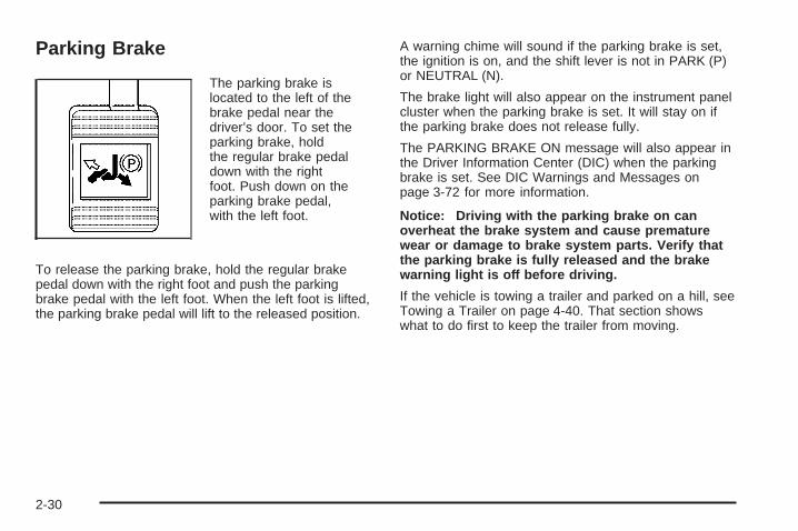
Parking Brake
The parking brake islocated to the left of thebrake pedal near thedriver’s door. To set theparking brake, holdthe regular brake pedaldown with the rightfoot. Push down on theparking brake pedal,with the left foot.
To release the parking brake, hold the regular brakepedal down with the right foot and push the parkingbrake pedal with the left foot. When the left foot is lifted,the parking brake pedal will lift to the released position.
A warning chime will sound if the parking brake is set,the ignition is on, and the shift lever is not in PARK (P)or NEUTRAL (N).
The brake light will also appear on the instrument panelcluster when the parking brake is set. It will stay on ifthe parking brake does not release fully.
The PARKING BRAKE ON message will also appear inthe Driver Information Center (DIC) when the parkingbrake is set. See DIC Warnings and Messages onpage 3-72 for more information.
Notice: Driving with the parking brake on canoverheat the brake system and cause prematurewear or damage to brake system parts. Verify thatthe parking brake is fully released and the brakewarning light is off before driving.
If the vehicle is towing a trailer and parked on a hill, seeTowing a Trailer on page 4-40. That section showswhat to do first to keep the trailer from moving.
2-30

Shifting Into Park (P)
{CAUTION:
It can be dangerous to get out of your vehicle ifthe shift lever is not fully in PARK (P) with theparking brake firmly set. Your vehicle can roll. Ifyou have left the engine running, the vehiclecan move suddenly. You or others could beinjured. To be sure your vehicle will not move,even when you are on fairly level ground, usethe steps that follow. If you are pulling a trailer,see Towing a Trailer on page 4-40.
1. Hold the brake pedal down with your right foot andset the parking brake.
2. Move the shift lever into PARK (P) by holding in thebutton on the shift lever and pushing the shift leverall the way toward the front of the vehicle.
3. Turn the ignition key to OFF.
4. Remove the key and take it with you. If you canleave your vehicle with the ignition key in yourhand, your vehicle is in PARK (P).
Leaving Your Vehicle With theEngine Running
{CAUTION:
It can be dangerous to leave your vehicle withthe engine running. Your vehicle could movesuddenly if the shift lever is not fully inPARK (P) with the parking brake firmly set.And, if you leave the vehicle with the enginerunning, it could overheat and even catch fire.You or others could be injured. Do not leaveyour vehicle with the engine running.
If you have to leave your vehicle with the enginerunning, be sure your vehicle is in PARK (P) and yourparking brake is firmly set before you leave it. After youhave moved the shift lever into PARK (P), hold theregular brake pedal down. Then, see if you can movethe shift lever away from PARK (P) without first pushingthe button.
If you can, it means that the shift lever was not fullylocked in PARK (P).
2-31

Torque LockIf you are parking on a hill and you do not shift yourtransaxle into PARK (P) properly, the weight of thevehicle may put too much force on the parking pawl inthe transaxle. You may find it difficult to pull the shiftlever out of PARK (P). This is called torque lock.To prevent torque lock, set the parking brake and thenshift into PARK (P) properly before you leave thedriver’s seat. To find out how, see Shifting Into Park (P)on page 2-31.
When you are ready to drive, move the shift lever out ofPARK (P) before you release the parking brake.
If torque lock does occur, you may need to have anothervehicle push your vehicle a little uphill to take some ofthe pressure from the parking pawl in the transaxle,so you can pull the shift lever out of PARK (P).
Shifting Out of Park (P)The vehicle has an automatic transaxle shift lock controlsystem which locks the shift lever in PARK (P) whenthe ignition is in OFF. In addition, the regular brakesmust be fully applied before shifting from PARK (P) whilethe ignition is in RUN. See Automatic TransaxleOperation on page 2-25.
If the vehicle cannot be shifted out of PARK (P), easepressure on the shift lever and push the shift lever all theway up into PARK (P) as brake application is maintained.Then move the shift lever into the desired gear.
If the brake pedal is held down but the vehicle stillcannot be shifted out of PARK (P), try this:
1. Turn the key to ACC.
2. Apply and hold the brake until the end of Step 4.
3. Shift the transaxle to NEUTRAL (N).
4. Start the vehicle and then shift to the desiredtransaxle gear.
5. Have the system fixed as soon as possible.
2-32
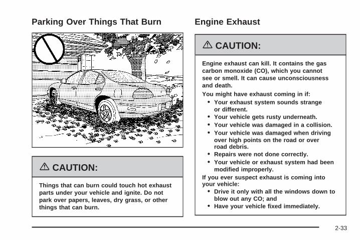
Parking Over Things That Burn
{CAUTION:
Things that can burn could touch hot exhaustparts under your vehicle and ignite. Do notpark over papers, leaves, dry grass, or otherthings that can burn.
Engine Exhaust
{CAUTION:
Engine exhaust can kill. It contains the gascarbon monoxide (CO), which you cannotsee or smell. It can cause unconsciousnessand death.You might have exhaust coming in if:
• Your exhaust system sounds strangeor different.
• Your vehicle gets rusty underneath.• Your vehicle was damaged in a collision.• Your vehicle was damaged when driving
over high points on the road or overroad debris.
• Repairs were not done correctly.• Your vehicle or exhaust system had been
modified improperly.If you ever suspect exhaust is coming intoyour vehicle:
• Drive it only with all the windows down toblow out any CO; and
• Have your vehicle fixed immediately.
2-33

Running the Engine While ParkedIt is better not to park with the engine running. But if youever have to, here are some things to know.
{CAUTION:
Idling the engine with the climate controlsystem off could allow dangerous exhaust intoyour vehicle. See the earlier caution underEngine Exhaust on page 2-33.
Also, idling in a closed-in place can let deadlycarbon monoxide (CO) into your vehicle even ifthe climate control fan is at the highest setting.One place this can happen is a garage.Exhaust — with CO — can come in easily.NEVER park in a garage with the enginerunning.
Another closed-in place can be a blizzard. SeeWinter Driving on page 4-28.
{CAUTION:
It can be dangerous to get out of your vehicleif the shift lever is not fully in PARK (P) withthe parking brake firmly set. Your vehicle canroll. Do not leave your vehicle when the engineis running unless you have to. If you have leftthe engine running, the vehicle can movesuddenly. You or others could be injured. Tobe sure your vehicle will not move, even whenyou are on fairly level ground, always set yourparking brake and move the shift lever toPARK (P).
Follow the proper steps to be sure your vehicle will notmove. See Shifting Into Park (P) on page 2-31.
If you are parking on a hill and if you are pulling atrailer, also see Towing a Trailer on page 4-40.
2-34

Mirrors
Manual Rearview Mirrorwith OnStar ®
Your vehicle has this feature located at the bottom ofthe mirror, to change the mirror from the day to the nightposition. To reduce the glare of headlamps frombehind, turn the control counterclockwise. To return themirror to the day position, turn the control clockwise.
There are also three OnStar® buttons located atthe bottom of the mirror face. See your dealer for moreinformation on the system and how to subscribe toOnStar®. See OnStar® System on page 2-38 for moreinformation about the services OnStar® provides.
Automatic Dimming RearviewMirror with Compass andTemperature DisplayIf the vehicle has this feature, the automatic dimmingmirror automatically dims to the proper level to minimizeglare at night from lights behind your vehicle.
The mirror also has a dual display in the upper rightcorner of the mirror that shows the compass reading andthe outside temperature.
Y On/Off: Press this button to operate the automaticdimming, compass and temperature features.
Automatic Dimming Mirror OperationThe automatic dimming mirror function is turned on eachtime the ignition is started. A light near the on/off buttonwill come on to indicate the automatic dimming is on.
If the automatic dimming function is off, press and holdthe on/off button for four seconds to manually turnthe system back on.
Temperature and Compass DisplayPress the on/off button, located in the center, to cyclebetween °F, °C and off. If the display reads CAL,the compass needs to be calibrated. For moreinformation, see “Compass Calibration” later inthis section.
If an abnormal temperature reading is displayed for anextended period of time, please consult your dealer.Under certain circumstances, a delay in updatingthe temperature is normal.
2-35
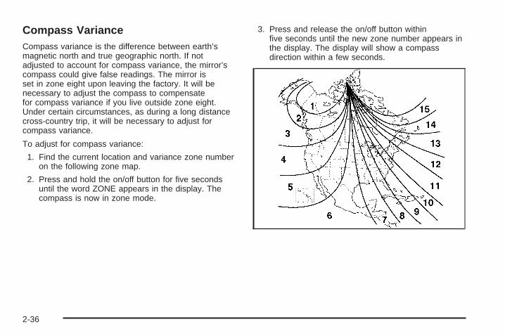
Compass VarianceCompass variance is the difference between earth’smagnetic north and true geographic north. If notadjusted to account for compass variance, the mirror’scompass could give false readings. The mirror isset in zone eight upon leaving the factory. It will benecessary to adjust the compass to compensatefor compass variance if you live outside zone eight.Under certain circumstances, as during a long distancecross-country trip, it will be necessary to adjust forcompass variance.
To adjust for compass variance:
1. Find the current location and variance zone numberon the following zone map.
2. Press and hold the on/off button for five secondsuntil the word ZONE appears in the display. Thecompass is now in zone mode.
3. Press and release the on/off button withinfive seconds until the new zone number appears inthe display. The display will show a compassdirection within a few seconds.
2-36

Compass CalibrationThe compass may need calibration if one of thefollowing occurs:
• If CAL is displayed while driving in the vehicle.
• After approximately five seconds, the display doesnot show a compass heading (N for North, forexample), there may be a strong magnetic fieldinterfering with the compass. Such interference maybe caused by a magnetic antenna mount, magneticnote pad holder, or a similar magnetic item.
• The compass does not display the correct headingand the compass zone variance is set correctly.
In order to calibrate, CAL must be displayed in themirror compass windows. If CAL is not displayed, pushin the on/off button for approximately eight secondsor until CAL is displayed.
The compass can be calibrated by driving the vehicle incircles at 5 mph (8 km/h) or less until the displayreads a direction.
Cleaning the MirrorWhen cleaning the mirror, use a paper towel or similarmaterial dampened with glass cleaner. Do not sprayglass cleaner directly on the mirror as that may causethe liquid cleaner to enter the mirror housing.
Outside Power Mirrors
The power mirror controlsare located near thedriver’s window, on thedriver’s door armrest.
Move the top control to the left to adjust the driver’sside outside mirror. Move the control to the rightto adjust the passenger’s side mirror. The centerposition turns the power control off and will not allow themirrors to move if the control pad is touched.
The round control pad adjusts the angle of the selectedoutside mirror. Press the arrows on the control padto adjust the angle of the mirror. Adjust each mirror sothat the sides and the area behind the vehicle canbe seen.
2-37

Outside Convex Mirror
{CAUTION:
A convex mirror can make things (like othervehicles) look farther away than they really are.If you cut too sharply into the right lane, youcould hit a vehicle on your right. Check yourinside mirror or glance over your shoulderbefore changing lanes.
The passenger’s outside rearview mirror is convex. Thesurface is curved so more area can be seen from thedriver’s seat. It also make things look farther away thanthey really are.
OnStar ® System
OnStar® uses global positioning system (GPS) satellitetechnology, wireless communications, and liveadvisors to provide you with a wide range of safety,security, information, and convenience services. If yourairbags deploy, the system is designed to make anautomatic call to OnStar® Emergency where wecan request emergency services be sent to yourlocation. If you lock your keys in the car, call OnStar® at1-888-4-ONSTAR and they can send a signal tounlock your doors. If you need roadside assistance,press the OnStar® button and they will get you the helpyou need.
2-38

A complete OnStar® User’s Guide and the Terms andConditions of the OnStar® Subscription ServiceAgreement are included in the vehicle’s glove boxliterature. For more information, visit www.onstar.com orwww.onstar.ca. Contact OnStar® at 1-888-4-ONSTAR(1-888-466-7827), or press the OnStar® button to speakto an OnStar® advisor 24 hours a day, 7 days a week.
Terms and conditions of the Subscription ServiceAgreement can be found at www.onstar.com orwww.onstar.ca.
OnStar ® ServicesFor new vehicles equipped with OnStar®, the Safe andSound Plan is included for one year from the date ofpurchase. You can extend this plan beyond thefirst year, or upgrade to the Directions and Connections®
Plan to meet your needs. For more information, pressthe OnStar® button to speak to an advisor.
Safe and Sound Plan• Automatic Notification of Airbag Deployment
• Emergency Services
• Roadside Assistance
• Stolen Vehicle Tracking
• AccidentAssist
• Remote Door Unlock/Vehicle Alert
• Remote Diagnostics
• Online Concierge
Directions and Connections ® Plan• All Safe and Sound Plan Services
• Driving Directions
• RideAssist
• Information and Convenience Services
2-39

OnStar ® Personal CallingAs an OnStar® subscriber, the Personal Callingcapability allows you to make hands-free calls using awireless system that is integrated into the vehicle.Calls can be placed nationwide using simple voicecommands with no additional contracts and no additionalroaming charges. To find out more about OnStar®
Personal Calling, refer to the OnStar® User’s Guide inthe vehicle’s glove box, visit www.onstar.com orwww.onstar.ca, or speak to an OnStar® advisor bypressing the OnStar® button or calling 1-888-4-ONSTAR(1-888-466-7827).
OnStar ® Virtual AdvisorYour vehicle may have Virtual Advisor. It is a feature ofOnStar® Personal Calling that uses minutes to accessweather, local traffic reports, and stock quotes. Bypressing the phone button and giving a few simple voicecommands, you can browse through the varioustopics. Customize your information profile atwww.myonstar.com. See the OnStar® User’s Guide formore information.
OnStar ® Steering Wheel Controls
Your vehicle may beequipped with a Talk/Mutebutton that can be used tointeract with OnStar®. Seethe Audio Steering WheelControl section for yourspecific vehicle operation.
When calling into voice mail systems, or to dial directorynumbers, press this button once, wait for the response,say the number(s) to be dialed, wait for the number(s)to be repeated and then say “dial”. See the OnStar®
User’s Guide for more information.
Storage Areas
Glove BoxOpen the glove box by lifting up on the lever. Close theglove box with a firm push.
2-40

Cupholder(s)There are two cupholders in the front of thecenter console.
Cupholder Installation
Your vehicle may also have a rear cupholder that canbe installed by aligning it to the console and snapping itinto place.
Cupholder Removal
Remove the rear cupholder by pulling it from theconsole.
2-41
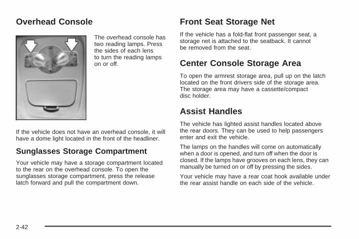
Overhead Console
The overhead console hastwo reading lamps. Pressthe sides of each lensto turn the reading lampson or off.
If the vehicle does not have an overhead console, it willhave a dome light located in the front of the headliner.
Sunglasses Storage CompartmentYour vehicle may have a storage compartment locatedto the rear on the overhead console. To open thesunglasses storage compartment, press the releaselatch forward and pull the compartment down.
Front Seat Storage NetIf the vehicle has a fold-flat front passenger seat, astorage net is attached to the seatback. It cannotbe removed from the seat.
Center Console Storage AreaTo open the armrest storage area, pull up on the latchlocated on the front drivers side of the storage area.The storage area may have a cassette/compactdisc holder.
Assist HandlesThe vehicle has lighted assist handles located abovethe rear doors. They can be used to help passengersenter and exit the vehicle.
The lamps on the handles will come on automaticallywhen a door is opened, and turn off when the door isclosed. If the lamps have grooves on each lens, they canmanually be turned on or off by pressing the sides.
Your vehicle may have a rear coat hook available underthe rear assist handle on each side of the vehicle.
2-42

Convenience NetThe vehicle may have a convenience net located on theback wall of the trunk.
Put small loads, like grocery bags, behind the net. It canhelp keep them from falling over.
The net is not for larger, heavier loads. Store those inthe trunk as far forward as possible.
Unhook the net so that it will lie flat when not in use.
SunroofIf the vehicle has a sunroof, it includes a sliding glasspanel and a sunshade.
The switch to control thesunroof is located in theheadliner.
The switch works only while the ignition is on, or inACC, or Retained Accessory Power (RAP) is on. SeeRetained Accessory Power (RAP) on page 2-22.
Vent: Open the sunshade by hand. Push the switchtoward the rear of the vehicle once and the sunroofwill open to the vent position. Push the switch forwardto close.
Open/Express-Open: Push the switch toward the rearof the vehicle a second time and the sunroof willopen the remainder of the way. The sunshade will openwith the sunroof if the switch is pushed toward therear of the vehicle twice.
Close: Push and hold the front of the switch until thesunroof motor stops. The sunshade must be closedby hand.
2-43

✍ NOTES
2-44

Instrument Panel Overview ...............................3-4Hazard Warning Flashers ................................3-6Other Warning Devices ...................................3-6Horn .............................................................3-6Tilt Wheel .....................................................3-6Turn Signal/Multifunction Lever .........................3-7Turn and Lane-Change Signals ........................3-7Headlamp High/Low-Beam Changer ..................3-8Flash-to-Pass .................................................3-9Windshield Wiper Lever ...................................3-9Cruise Control ..............................................3-11Exterior Lamps .............................................3-15Headlamps on Reminder ................................3-15Daytime Running Lamps (DRL) .......................3-16Fog Lamps ..................................................3-17Exterior Lighting Battery Saver ........................3-17Interior Lamps ..............................................3-17Instrument Panel Brightness ...........................3-18Courtesy Lamps ...........................................3-18Entry Lighting ...............................................3-18Delayed Entry Lighting ...................................3-19Delayed Exit Lighting .....................................3-19Front Reading Lamps ....................................3-20Overhead Console Reading Lamps .................3-20
Rear Assist Handle Reading Lamps ................3-20Battery Run-Down Protection ..........................3-20Head-Up Display (HUD) .................................3-21Accessory Power Outlet(s) .............................3-24Ashtray(s) and Cigarette Lighter ......................3-25
Climate Controls ............................................3-26Climate Control System .................................3-26Dual Automatic Climate Control System ...........3-29Outlet Adjustment .........................................3-33Passenger Compartment Air Filter ...................3-33
Warning Lights, Gages, and Indicators ............3-35Instrument Panel Cluster ................................3-36Speedometer and Odometer ...........................3-37Tachometer .................................................3-37Safety Belt Reminder Light .............................3-38Passenger Safety Belt Reminder Light .............3-38Airbag Readiness Light ..................................3-39Passenger Airbag Status Indicator ...................3-40Up-Shift Light ...............................................3-42Brake System Warning Light ..........................3-42Anti-Lock Brake System Warning Light .............3-44Traction Control System (TCS) Warning Light ....3-45Enhanced Traction System Warning Light .........3-45
Section 3 Instrument Panel
3-1

Engine Coolant Temperature Warning Light ......3-46Engine Coolant Temperature Gage ..................3-46Malfunction Indicator Lamp .............................3-47Oil Pressure Light .........................................3-50Fog Lamp Light ............................................3-50Cruise Control Light ......................................3-51Highbeam On Light .......................................3-51Fuel Gage ...................................................3-51
Driver Information Center (DIC) .......................3-52DIC Controls and Displays (Base Level DIC) ....3-52DIC Controls and Displays (Uplevel DIC
with Trip Computer) ...................................3-60DIC Warnings and Messages .........................3-72
Audio System(s) .............................................3-94Setting the Time ...........................................3-96Radio with CD (Base Level) ...........................3-96Radio with CD (MP3) ..................................3-107Radio with Six-Disc CD ................................3-123Navigation/Radio System ..............................3-139Theft-Deterrent Feature ................................3-139Audio Steering Wheel Controls ......................3-139Radio Reception .........................................3-140Care of Your CDs .......................................3-141Care of the CD Player .................................3-141Backglass Antenna ......................................3-141XM™ Satellite Radio Antenna System ............3-142Chime Level Adjustment ...............................3-142
Section 3 Instrument Panel
3-2

✍ NOTES
3-3
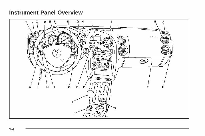
Instrument Panel Overview
3-4

The main components of the instrument panel are the following:
A. Side Window Defogger Outlets. See OutletAdjustment on page 3-33.
B. Air Outlets. See Outlet Adjustment on page 3-33.C. Turn Signal/Multifunction Lever and Cruise Controls.
See Turn Signal/Multifunction Lever on page 3-7and Cruise Control on page 3-11.
D. TAP-Shift® Control (If Equipped). See AutomaticTransaxle Operation on page 2-25.
E. Hazard Warning Flashers Button. See HazardWarning Flashers on page 3-6.
F. Instrument Panel Cluster. See Instrument PanelCluster on page 3-36.
G. Windshield Wiper Lever. See Windshield WiperLever on page 3-9.
H. Ignition. See Ignition Positions on page 2-22.I. Driver Information Center (DIC). See Driver
Information Center (DIC) on page 3-52.J. Audio System. See Audio System(s) on page 3-94.K. Audio Steering Wheel Controls (If Equipped).
See Audio Steering Wheel Controls on page 3-139.
L. Hood Release. See Hood Release on page 5-11.M. Tilt Steering Wheel Lever, on Steering Column. See
Tilt Wheel on page 3-6.N. Interior Lamps Brightness Control. See Interior
Lamps on page 3-17.O. Passenger Air Bag Status Indicator. See Passenger
Airbag Status Indicator on page 3-40.P. Climate Controls. See Climate Control System on
page 3-26.Q. Shift Lever. See Automatic Transaxle Operation on
page 2-25.R. Traction Control Button. See Traction Control
System (TCS) on page 4-9.S. Head Up Display (HUD) Control. See Head-Up
Display (HUD) on page 3-21.T. Glove Box. See Glove Box on page 2-40.U. Instrument Panel Fuse Block. See Instrument Panel
Fuse Block on page 5-112.
3-5

Hazard Warning FlashersYour hazard warning flashers let you warn others. Theyalso let police know you have a problem. Your frontand rear turn signal lamps will flash on and off.
The hazard warningflasher button is located ontop of the steeringcolumn.
Your hazard warning flashers work no matter whatposition your key is in, and even if the key is not inthe ignition.
Press the button to make the front and rear turn signallamps flash on and off. Press the button again toturn the flashers off.
When the hazard warning flashers are on, your turnsignals will not work.
Other Warning DevicesIf you carry reflective triangles, you can set them up atthe side of the road about 300 feet (100 m) behindyour vehicle.
HornPress the vehicle’s steering wheel pad to soundthe horn.
Tilt WheelA tilt wheel enables the position of the steering wheel tobe adjusted. The lever that lets the steering wheel tiltis located on the outboard side of the steering column.
To tilt the steering wheel, hold it and pull the lever.Move the steering wheel to a comfortable drivingposition and release the lever to lock it into place.Tilt the steering wheel to the highest position to givemore room when exiting and entering the vehicle.
3-6

Turn Signal/Multifunction Lever
The lever on the left side of the steering columnincludes the following:• G Turn and Lane-Change Signals. See Turn and
Lane-Change Signals on page 3-7.• 3 Headlamp High/Low-Beam Changer. See
Headlamp High/Low-Beam Changer on page 3-8.• - Fog Lamps. See Fog Lamps on page 3-17.
• Flash-to-Pass Feature. See Flash-to-Pass onpage 3-9.
• I Cruise Control. See Cruise Control onpage 3-11.
• P Exterior Lamps Control. See Exterior Lamps onpage 3-15.
Turn and Lane-Change SignalsTo signal a turn, move the turn signal lever located onthe left side of the steering column all the way upor down. The lever returns automatically when the turnis complete.
An arrow on the instrumentpanel cluster will flash inthe direction of theturn or lane change.
If the vehicle is equipped with the Head-Up-Display(HUD), a right or left turn signal will appear in the HUDarea when making turns or lane changes. SeeHead-Up Display (HUD) on page 3-21 for moreinformation.
Raise or lower the lever until the arrow starts to flash tosignal a lane change. Hold it there until the lanechange is complete. The lever returns to its originalposition when it is released.
3-7

Arrows that flash rapidly when signaling for a turn orlane change may be caused by a burned-out signal bulb.Other drivers will not see the signal.
Replace burned-out bulbs to help avoid possibleaccidents. See Replacement Bulbs on page 5-59, FrontTurn Signal, Parking and Fog Lamps on page 5-56,and Taillamps, Turn Signal, and Stoplamps onpage 5-57. Also, check the fuse for burned-out bulbs if aturn signal arrow fails to work when signaling a turn.See Fuses and Circuit Breakers on page 5-112 forlocation information.
Turn Signal On ChimeIf the turn signal is left on for more than 0.75 of a mile(1.21 km), a warning chime will sound and the TURNSIGNAL ON warning message will appear on the DriverInformation Center (DIC) display. See “Turn SignalOn” under DIC Warnings and Messages on page 3-72.
Headlamp High/Low-Beam ChangerPush forward on the exterior lamps control lever tochange the headlamps from low to high-beam. Pull thelever back and then release it to change from highto low-beam.
This symbol appears onthe instrument panel clusterwhen the high-beamheadlamps are on.
When the high-beam headlamps are on, the fog lampswill not be on. If the vehicle is equipped with theHead-Up-Display (HUD) an arrow will appear in theHUD area indicating that the high-beams are on. SeeHead-Up Display (HUD) on page 3-21 for moreinformation.
3-8
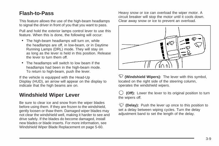
Flash-to-PassThis feature allows the use of the high-beam headlampsto signal the driver in front of you that you want to pass.
Pull and hold the exterior lamps control lever to use thisfeature. When this is done, the following will occur:
• The high-beam headlamps will turn on, whilethe headlamps are off, in low-beam, or in DaytimeRunning Lamps (DRL) mode. They will stay onas long as the lever is held in this position. Releasethe lever to turn them off.
• The headlamps will switch to low beam if theheadlamps had been in the high-beam mode.To return to high-beam, push the lever.
If the vehicle is equipped with the Head-UpDisplay (HUD), an arrow will appear on the display toindicate that the high beams are on.
Windshield Wiper LeverBe sure to clear ice and snow from the wiper bladesbefore using them. If they are frozen to the windshield,gently loosen or thaw them. Damaged wiper blades maynot clear the windshield well, making it harder to see anddrive safely. If the blades do become damaged, installnew blades or blade inserts. For more information, seeWindshield Wiper Blade Replacement on page 5-60.
Heavy snow or ice can overload the wiper motor. Acircuit breaker will stop the motor until it cools down.Clear away snow or ice to prevent an overload.
N(Windshield Wipers): The lever with this symbol,located on the right side of the steering column,operates the windshield wipers.
9 (Off): Lower the lever to its original position to turnthe wipers off.
& (Delay): Push the lever up once to this position toset a delay between wiping cycles. Turn the delayadjustment band to set the length of the delay.
3-9

x (Delay Adjustment): Turn the band, located onthe left of the windshield wiper lever, to set the length ofthe delay between wiper cycles when using the delayfeature. There are five delay adjustment settings.Turn the band up to make the delays shorter in betweenwiper cycles. Turn the band down to make the delayslonger between wiper cycles. The windshield wiper levermust be in delay for this feature to work.
6 (Low Speed): Push the lever up to the secondposition for steady wiping cycles at a slow speed.
1 (High Speed): Push the lever up to the thirdposition for steady wiping cycles at a high speed.
7 (Mist): For a single wiping cycle, push thelever down once and let go. The wipers will stop afterone cycle. For additional cycles, hold the lever down.
About 30 seconds after the wipers are on, theheadlamps, taillamps, and instrument panel lighting willcome on, and the Driver Information Center (DIC)back lighting will decrease to the night time mode. Aboutten seconds after the wipers are turned off, all thelamps will go back to the AUTO (Automatic) mode. SeeExterior Lamps on page 3-15.
Windshield Washer
{CAUTION:
In freezing weather, do not use your washeruntil the windshield is warmed. Otherwise thewasher fluid can form ice on the windshield,blocking your vision.
The windshield washer button is located at the end ofthe windshield wiper lever.
K (Washer Fluid): Press this button to activate thewasher fluid to spray onto the windshield. The wiperswill run for a few cycles to clear the windshield. For morewash cycles, press and hold the button.
If the vehicle is low on washer fluid, the LOW WASHERFLUID message will appear on the Driver InformationCenter (DIC) display. See “LOW WASHER FLUID”under DIC Warnings and Messages on page 3-72 formore information.
3-10

Cruise Control
{CAUTION:
Cruise control can be dangerous where youcannot drive safely at a steady speed. So, donot use your cruise control on winding roadsor in heavy traffic.
Cruise control can be dangerous on slipperyroads. On such roads, fast changes in tiretraction can cause needless wheel spinning,and you could lose control. Do not use cruisecontrol on slippery roads.
9(Off): This positionturns the system off.
R(On): This position activates the system.
+ (Resume/Accelerate): Move the lever to this symbolto make the vehicle accelerate or resume to apreviously set speed.
T(Set): Press this button to set the speed.
With cruise control, you can maintain a speed of about25 mph (40 km/h) or more without keeping your footon the accelerator. This can really help on longtrips. Cruise control does not work at speeds belowabout 25 mph (40 km/h).
3-11

Cruise control will not work if your parking brake is set,or if the master cylinder brake fluid level is low.
{CAUTION:
Cruise control can be dangerous where youcannot drive safely at a steady speed. So, donot use your cruise control on winding roadsor in heavy traffic.
Cruise control can be dangerous on slipperyroads. On such roads, fast changes in tiretraction can cause needless wheel spinning,and you could lose control. Do not use cruisecontrol on slippery roads.
If your vehicle is in cruise control when the tractioncontrol system (if equipped) begins to limit wheel spin,the cruise control will automatically disengage. SeeTraction Control System (TCS) on page 4-9. When roadconditions allow you to safely use it again, you mayturn cruise control back on.
Setting Cruise Control
{CAUTION:
If you leave your cruise control on when youare not using cruise, you might hit a buttonand go into cruise when you do not want to.You could be startled and even lose control.Keep the cruise control switch off until youwant to use cruise control.
1. Move the cruise control switch to on.
2. Get up to the speed you want.
3. Press in the set button at the end of the lever andrelease it.
4. Take your foot off the accelerator pedal.
This symbol, along withthe CRUISE SETmessage, will brieflyappear in the DriverInformation Center (DIC)when the cruisecontrol is set.
3-12

The CRUISE SET message will also appearbriefly on the Head-Up Display (HUD), if equipped,when the cruise control lever is pushed to the minus(set/coast/decelerate) or the plus (resume/accelerate)positions.
A cruise control light will also appear on the instrumentpanel cluster when the cruise control is on. This lightwill disappear when the brakes are applied or the cruisecontrol is cancelled. It will reappear when the setcruise speed is resumed. The light will go out when thecruise control is turned off. See Cruise Control Lighton page 3-51.
Resuming a Set SpeedOnce you’re going about 25 mph (40 km/h) or more, youcan move the cruise control switch briefly from on toresume/accelerate.
Your vehicle will go right back up to your chosen speedand stay there.
If you hold the switch at resume/accelerate the vehiclewill keep going faster until you release the switch orapply the brake. So unless you want to go faster, don’thold the switch at resume/accelerate.
Increasing Speed While UsingCruise ControlThere are two ways to go to a higher speed:
• Use the accelerator pedal to get to the higherspeed. Press the set button at the end of the lever,then release the button and the acceleratorpedal. You’ll now cruise at the higher speed. If theaccelerator pedal is held longer than 60 seconds,cruise control will turn off.
• Move the cruise switch from on toresume/accelerate. Hold it there until you get up tothe speed you want, and then release the switch.To increase your speed in very small amounts,move the switch briefly to resume/accelerate. Eachtime you do this, your vehicle will go about1 mph (1.6 km/h) faster.
The acceleration feature will only work after the cruisecontrol speed has been set by pushing the cruise controlset button.
3-13

Reducing Speed While Using CruiseControlThere are two ways to reduce the vehicle’s speed whileusing cruise control:
• Press and hold the set button until you reach thelower speed you want, then release it.
• To slow down in very small amounts, briefly pressthe set button. Each time you do this your vehiclewill slow down approximately one mph (1.6 km/h).
Passing Another Vehicle While UsingCruise ControlUse the accelerator pedal to increase the vehicle’sspeed. When you take your foot off the pedal, thevehicle will slow down to the cruise control speedset earlier.
Using Cruise Control on HillsHow well the cruise control will work on hills dependsupon the vehicle’s speed, its load, and the steepness ofthe hills. When going up steep hills, the acceleratorpedal might have to be used in order to maintainthe vehicle’s speed. When going downhill, the brakesmight have to be applied, or the transaxle might have tobe shifted to a lower gear to keep the vehicle’s speeddown. Doing either of these things will take thevehicle out of cruise. It may be better not to use thecruise control if the brakes constantly have to beapplied, or the vehicle continuously needs to be shiftedto a lower gear.
Ending Cruise ControlThere are two ways to turn off the cruise control:
• Step lightly on the brake pedal
• Move the cruise control switch to off
Erasing Speed MemoryWhen the cruise control or the ignition is turned off, thecruise control set speed memory is erased.
3-14
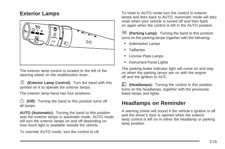
Exterior Lamps
The exterior lamp control is located to the left of thesteering wheel on the multifunction lever.
O (Exterior Lamp Control): Turn the band with thissymbol on it to operate the exterior lamps.
The exterior lamp band has four positions:
O (Off): Turning the band to this position turns offall lamps.
AUTO (Automatic): Turning the band to this positionsets the exterior lamps in automatic mode. AUTO modewill turn the exterior lamps on and off depending onhow much light is available outside the vehicle.
To override AUTO mode, turn the control to off.
To reset to AUTO mode turn the control to exteriorlamps and then back to AUTO. Automatic mode will alsoreset when your vehicle is turned off and then backon again when the control is left in the AUTO position.
; (Parking Lamp): Turning the band to this positionturns on the parking lamps together with the following:
• Sidemarker Lamps
• Taillamps
• License Plate Lamps
• Instrument Panel Lights
The parking brake indicator light will come on and stayon when the parking lamps are on with the engineoff and the ignition to ACC.
5 (Headlamps): Turning the control to this positionturns on the headlamps, together with the previouslylisted lamps and lights.
Headlamps on ReminderA warning chime will sound if the vehicle’s ignition is offand the driver’s door is opened when the exteriorlamp control is left on in either the headlamp or parkinglamp position.
3-15

Daytime Running Lamps (DRL)Daytime Running Lamps (DRL) can make it easier forothers to see the front of your vehicle during theday. DRL can be helpful in many different drivingconditions, but they can be especially helpful in the shortperiods after dawn and before sunset. Daytime runninglamps are required to function at all times on allvehicles first sold in Canada.
A light sensor on top of the instrument panel makes theDRL work, so be sure it is not covered.
The DRL system will make the low-beam headlampscome on at reduced brightness when the followingconditions are met:
• The ignition is on.
• The exterior lamps control is off.
• The parking brake is released.
While the DRL are on, only the vehicle’s low-beamheadlamps will be on at reduced brightness. The turnsignal, taillamps, sidemarker and other lamps will not beon. The instrument panel cluster will not be lit up either.
When it is dark enough outside, the DRL will turn offand the vehicle’s headlamps and parking lamps will turnon. The other lamps that come on with the headlampswill also come on.
When it is bright enough outside, the headlamps will gooff and the DRL will come on.
To idle the vehicle with the DRL off, turn the exteriorlamp control off and then do one of the following:
• Turn the exterior lamp control to the parkinglamp position.
• Turn the exterior lamp control to theheadlamp position.
• Turn the exterior lamp control from AUTO to off andback to AUTO.
This feature is not available for vehicles first soldin Canada.
To turn off the automatic headlamp feature when it isdark outside, move the exterior lamp control to theparking lamp position. The parking lamps will remainilluminated and the headlamps will turn off. Thefog lamps will also go on if they were on previously.
As with any vehicle, the regular headlamp systemshould be turned on when needed.
3-16
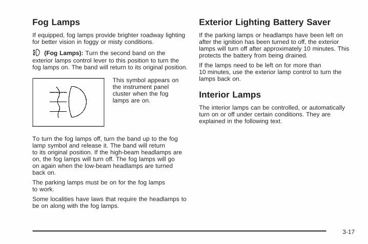
Fog LampsIf equipped, fog lamps provide brighter roadway lightingfor better vision in foggy or misty conditions.
- (Fog Lamps): Turn the second band on theexterior lamps control lever to this position to turn thefog lamps on. The band will return to its original position.
This symbol appears onthe instrument panelcluster when the foglamps are on.
To turn the fog lamps off, turn the band up to the foglamp symbol and release it. The band will returnto its original position. If the high-beam headlamps areon, the fog lamps will turn off. The fog lamps will goon again when the low-beam headlamps are turnedback on.
The parking lamps must be on for the fog lampsto work.
Some localities have laws that require the headlamps tobe on along with the fog lamps.
Exterior Lighting Battery SaverIf the parking lamps or headlamps have been left onafter the ignition has been turned to off, the exteriorlamps will turn off after approximately 10 minutes. Thisprotects the battery from being drained.
If the lamps need to be left on for more than10 minutes, use the exterior lamp control to turn thelamps back on.
Interior LampsThe interior lamps can be controlled, or automaticallyturn on or off under certain conditions. They areexplained in the following text.
3-17
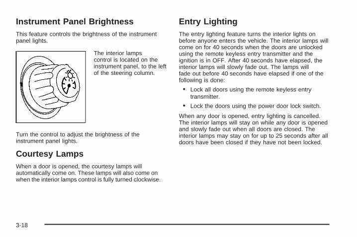
Instrument Panel BrightnessThis feature controls the brightness of the instrumentpanel lights.
The interior lampscontrol is located on theinstrument panel, to the leftof the steering column.
Turn the control to adjust the brightness of theinstrument panel lights.
Courtesy LampsWhen a door is opened, the courtesy lamps willautomatically come on. These lamps will also come onwhen the interior lamps control is fully turned clockwise.
Entry LightingThe entry lighting feature turns the interior lights onbefore anyone enters the vehicle. The interior lamps willcome on for 40 seconds when the doors are unlockedusing the remote keyless entry transmitter and theignition is in OFF. After 40 seconds have elapsed, theinterior lamps will slowly fade out. The lamps willfade out before 40 seconds have elapsed if one of thefollowing is done:
• Lock all doors using the remote keyless entrytransmitter.
• Lock the doors using the power door lock switch.
When any door is opened, entry lighting is cancelled.The interior lamps will stay on while any door is openedand slowly fade out when all doors are closed. Theinterior lamps may stay on for up to 25 seconds after alldoors have been closed if they have not been locked.
3-18

Delayed Entry LightingThe delayed lighting feature will continue to light theinterior of the vehicle for 25 seconds after all the doorshave been closed. Delayed lighting will not occurwhile the ignition is in RUN or ACC. After 25 secondshave elapsed, the interior lamps will slowly fade out. Thelamps will fade out before the 25 seconds haveelapsed if one of the following is done:
• The ignition is turned to RUN or ACC.
• The doors are locked using the remote keylessentry transmitter.
• The doors are locked using the power doorlock switch.
To turn the delayed lighting feature off or on, see“Personal Programming Modes” under DIC Controls andDisplays (Base Level DIC) on page 3-52 or DICControls and Displays (Uplevel DIC with Trip Computer)on page 3-60 DIC Controls and Displays.
Delayed Exit LightingFor exiting the vehicle at night, the vehicle is equippedwith the delayed exit lighting feature. After the keyis removed from the ignition, the interior lamps will lightfor up the amount of seconds set in the DriverInformation Center (DIC). See “Personal ProgrammingMode Screens” under DIC Controls and Displays(Base Level DIC) on page 3-52 or DIC Controls andDisplays (Uplevel DIC with Trip Computer) onpage 3-60. After the set time has elapsed, the interiorlamps will slowly fade. The lamps will fade before the settime has elapsed if one of the following is done:• The ignition is turned to RUN or ACC.• The doors are locked using the remote keyless
entry transmitter.• The doors are locked using the power door
lock switch.When any door is opened, delayed exit lighting iscancelled. The interior lamps will stay on while any dooris opened and will slowly fade out when all the doorsare closed. The interior lamps will stay on for theset time after all the doors have been closed if theyhave not been locked.To turn the delayed exit lighting feature off or on, see“Personal Programming Mode Screens” under DICControls and Displays (Base Level DIC) on page 3-52or DIC Controls and Displays (Uplevel DIC with TripComputer) on page 3-60.
3-19

Front Reading LampsIf the vehicle has a sunroof, there are reading lamps infront of the sunroof switch located on the headliner.These lamps will come on when the doors are opened.Press the side of each reading lamp to turn them onand off when the doors are closed.
Overhead Console Reading LampsThe vehicle may have reading lamps on the overheadconsole. These lamps will turn on when the doorsare opened. When the doors are closed, press the sideof each lamp to turn them on and off.
Rear Assist Handle Reading LampsIf the vehicle has a reading lamp on each rear assisthandle, press the side of each lamp to turn it on or off.
Battery Run-Down ProtectionThe vehicle has a feature to help prevent the batteryfrom draining in case the interior, trunk, or underhoodlamps are accidentally left on. If any of these lamps areleft on while the ignition is in OFF, they will automaticallyturn off after 10 minutes. The lamps will not comeback on again until any of the following are done:
• The ignition is turned to RUN or ACC.
• The interior lamps control is turned completely tothe right, then back slightly to the left.
• Open, or close and reopen, a door that is closed.
If the vehicle has less than 15 miles (25 km) onthe odometer, the battery saver will turn off the lampsafter only three minutes.
3-20

Head-Up Display (HUD)
{CAUTION:
If the HUD image is too bright or too high inyour field of view, it may take you more time tosee things you need to see when it is darkoutside. Be sure to keep the HUD image dimand placed low in your field of view.
If the vehicle has the Head-Up Display (HUD), someinformation concerning the operation of the vehicleis projected onto the windshield. This includesthe speedometer reading, transaxle positions, compassdirection, outside air temperature, the tap shift gearand the upshift symbol if active, and a brief display ofthe current radio station, including XM information orCD track. It will also display turn-by-turn navigationinformation if the vehicle is equipped with a navigationradio. The images are projected by the HUD lenslocated on the driver’s side of the instrument panel.
The tap shift gear and the upshift symbol will alsoappear on the HUD if the vehicle is equipped with tapshift and it is active.
The HUD information can be displayed in one ofthree languages, English, French, or Spanish. Thespeedometer reading and other numerical values canbe displayed in either English or metric units.
The language selection and the units of measurementare changed through the trip computer in the DriverInformation Center (DIC). See “Options” underDIC Controls and Displays (Base Level DIC) onpage 3-52 or DIC Controls and Displays (Uplevel DICwith Trip Computer) on page 3-60.
The HUD information appears as an image focused outtoward the front of the vehicle.
3-21

When the ignition key is turned to RUN, the HUD willdisplay an introductory message for a short time,until the HUD has warmed up.
The following indicator lights come on the instrumentpanel when activated and will also appear on the HUD:
• Turn Signal Indicators
• High-Beam Indicator Symbol
The HUD will temporarily display CHECK TRIPCOMPUTER when there are messages on the DIC tripcomputer.
The HUD will also display the following messages whenthese systems, if equipped, are active:
• TRACTION CONTROL ACTIVE
• STABILITY CONTROL ACTIVE
The HUD will temporarily display the TRACTIONCONTROL OFF message when the traction controlsystem is turned off.
The HUD will temporarily display the CRUISE SETmessage when cruise control is activated or cruisespeed is increased.
Notice: If you try to use the HUD image as aparking aid, you may misjudge the distance anddamage your vehicle. Do not use the HUD image asa parking aid.
When the HUD is on, the speedometer reading willcontinually be displayed. The current radio station orCD track number will display for a short period of timeafter the radio or CD track status changes. This willhappen whenever one of the radio controls is pressed.
The speedometer size will be reduced when radio,CD information, warnings, or turn-by-turn navigationinformation are displayed on the HUD.
The HUD control is locatedon the console.
To adjust the HUD image so that items are properlydisplayed, do the following:
1. Adjust the driver’s seat to a comfortable position.
2. Start the engine.
3. Adjust the HUD controls.
3-22

Use the following settings to adjust the HUD.
9 (Off): Rotate the outer ring on the HUD control tothis position to turn the HUD off.
I II III IIII (Brightness): Turn the outer ring on the HUDcontrol clockwise to dim the display andcounterclockwise to brighten it.
w (Up): Press this portion of the switch on the HUDcontrol to move the image up.
x (Down): Press this portion of the switch on the HUDcontrol to move the image down. Move the image aslow as possible on the windshield, keeping it in full view.
? (Page): Press this button to select the displayformats. Release the page button when the formatnumber with the desired display is shown on the HUD.
• Format One: This display gives the speedometerreading (in English or metric units), transaxlepositions, compass direction, and the outside airtemperature.
• Format Two: This display includes the informationin Format One without the compass direction andthe outside air temperature.
• Format Three: This display includes all theinformation in Format One, but turns the instrumentcluster lighting off. Format three is only availableat night.
All formats will show the turn-by-turn navigationinformation. It will display the next turn, direction, streetname, and distance to the selected destination.When you near your destination, the HUD will display adistance bar that will fill in the closer you get to yourdestination. All navigation information is provided to theHUD by the navigation radio, if equipped.
The warning indicators still appear on the instrumentpanel when required. The HUD will display StealthMode On.
The HUD will store the last display format selected.If the last format displayed was Format One or FormatThree, then Format One will be displayed when thevehicle is started.
If the last format was Format Two, then Format Twowill be displayed.
The HUD image displayed on the windshield willautomatically dim and brighten to compensate foroutside lighting.
The HUD image can temporarily light up depending onthe angle and position of the sunlight on the HUDdisplay. This is normal and will change when the angleof the sunlight on the HUD display changes.
Polarized sunglasses could make the HUD imageharder to see.
3-23

Care of the HUDClean the inside of the windshield as needed to removeany dirt or film that could reduce the sharpness orclarity of the HUD image.To clean the HUD lens, use a soft, clean cloth that hashousehold glass cleaner sprayed on it. Wipe the HUDlens gently, then dry it. Do not spray cleaner directly onthe lens because the cleaner could leak into the unit.
If You Cannot See the HUD ImageWhen the Ignition Is On• Is anything covering the HUD lens?• Is the HUD dimmer setting bright enough?• Is the HUD image adjusted to the proper height?• Are you wearing polarized sunglasses?• Still no HUD image? Check the fuse in the
instrument panel fuse block. See Instrument PanelFuse Block on page 5-112.
If the HUD Image Is Not Clear• Is the HUD image too bright?• Are the windshield and HUD lens clean?
If the HUD image is not correct, contact your dealer.Keep in mind that the windshield is part of the HUDsystem. See Windshield Replacement on page 5-60.
Accessory Power Outlet(s)
The vehicle hastwo 12-volt outlets whichcan be used to plug inelectrical equipment.
One accessory power outlet is located on the centerconsole, below the front edge of the storage console.The other is located inside the console.
Remove the tethered cap to use the outlet. Whennot using the outlet, be sure to cover it with theprotective cap.
Notice: Leaving electrical equipment on forextended periods will drain the battery. Always turnoff electrical equipment when not in use and donot plug in equipment that exceeds the maximumamperage rating.
3-24

Certain electrical accessories may not be compatiblewith the accessory power outlet and could resultin blown vehicle or adapter fuses. See your dealer foradditional information on accessory power outlets.
Notice: Adding any electrical equipment to yourvehicle may damage it or keep other componentsfrom working as they should. The repairs would notbe covered by your warranty. Do not use equipmentexceeding maximum amperage rating. Checkwith your dealer before adding electrical equipment.
When adding electrical equipment, be sure to followthe proper installation instructions included with it.
Notice: Improper use of the power outlet can causedamage not covered by your warranty. Do nothang any type of accessory or accessory bracketfrom the plug because the power outlets aredesigned for accessory power plugs only.
Ashtray(s) and Cigarette Lighter
AshtrayNotice: If you put papers, pins, or other flammableitems in the ashtray, hot cigarettes or othersmoking materials could ignite them and possiblydamage your vehicle. Never put flammable items inthe ashtray.If your vehicle is equipped, the ashtray is located to theright of the transaxle shift lever on the center console.To open it, push and release the rear of the cover.To empty the ashtray, lift the side tab and pull upto remove the ashtray from the center console. Toreinstall, push the tray back into place.
Cigarette LighterNotice: Holding a cigarette lighter in while it isheating will not allow the lighter to back away fromthe heating element when it is hot. Damage fromoverheating may occur to the lighter or heatingelement, or a fuse could be blown. Do not hold acigarette lighter in while it is heating.If your vehicle is equipped with a cigarette lighter, it islocated on the center console.Push the lighter to activate the heating element andrelease it. Once the heating element is hot, it will pop outby itself.
3-25

Climate Controls
Climate Control SystemThe climate control system allows manual control of theheating, cooling, and ventilation in the vehicle.
Fan
9(Fan): Turn the knob by this symbol, located on theleft side of the climate control panel, clockwise orcounterclockwise to increase or decrease the fan speed.The fan speed will be temporarily reduced betweenthe transition to a new mode. The fan will resume theoriginal speed when the transition to the new modeis complete.
9(Off): Turn the knob to this position to turn theclimate control system off. Only the heated seat and/orrear defrost can be operated when the fan is off.
ModeTurn the middle knob to select the following modes:
H(Vent) (Outside Air): This mode directs outside airto the instrument panel outlets. If driving in city traffic,and the vehicle is stopped and idling, or the weather ishot, press the recirculation button. To prevent the airinside the vehicle from becoming stale, be sure to turnoff recirculation periodically.
)(Bi-Level): This mode directs half of the air to theinstrument panel outlets, and the remaining air tothe floor outlets. Some air may be directed toward thewindshield. Slightly cooler air is directed to theinstrument panel outlets and warmer air is directed tothe floor outlets.
6(Floor): This mode directs most of the air to thefloor outlets with some air directed toward the sidewindow outlets and a little air directed to the windshield.
In this mode, the system will automatically use outsideair. The air conditioning compressor will be engagedunless the outside temperature is 40°F (4°C) or below.
3-26

Recirculation cannot be selected when in this modeeven though the indicator light comes on whenthe recirculation button is pressed.
The middle knob on the climate control panel can alsobe used to select the defog or defrost mode.
Defogging and DefrostingFog on the inside of the vehicle is a result of highhumidity causing moisture to condense on the coolwindow glass. This can be minimized if the climatecontrol system is used properly. There are two modesto clear frost or fog from the windshield. Use thedefog mode to clear the windows of condensation andto warm the vehicle’s occupants. Use the defrostmode to remove frost or condensation from thewindshield quickly.
See “Rear Window Defogger” later in this section forinformation on clearing the rear window of fog or ice.
.(Floor/Defog): Use the floor/defog mode to clear thewindows of fog or moisture and to warm the passengers.This mode directs the air equally between thewindshield and the floor outlets, along with somedirected to the side window outlets.
This mode will automatically use outside air. The airconditioning compressor will be engaged unlessthe outside temperature is 40°F (4°C) or below.Recirculation cannot be selected when in this modeeven though the indicator light comes on whenthe recirculation button is pressed.
1 (Defrost): Use the defrost mode to remove fog orfrost from the windshield more quickly. This modedirects most of the air to the windshield and the sidewindow outlets, with some air directed to the flooroutlets. This mode has a timer and will shut off afterfive minutes.
This mode will automatically use outside air. The airconditioning compressor will be engaged unlessthe outside temperature is 40°F (4°C) or below.Recirculation cannot be selected when in this modeeven though the indicator light comes on whenthe recirculation button is pressed.
TemperatureThe knob on the right of the climate control panel is thetemperature adjustment that can be used with any ofthe climate control modes.
Turn the knob clockwise for warmer settings andcounterclockwise for colder settings.
3-27
Air Conditioning
#(Air Conditioner): Press this button to turn the airconditioning compressor on or off. An indicator lightto the right of the button will come on. This button hasno control over the air conditioning compressor when inFloor/Defog and Defrost modes. The instrumentpanel brightness control may have to be adjusted to thehighest setting in order to see the indicator. SeeInstrument Panel Brightness on page 3-18 foradditional information.
On hot days during the vehicle’s initial start-up, openthe windows to let hot inside air escape; then closethem. This helps to reduce the time it takes forthe vehicle to cool down. It also helps the system tooperate more efficiently.
For quicker cool down on hot days, do the following:
1. Select any mode setting between vent and thesetting before defrost.
2. Select the air conditioner.
3. Select the coolest temperature.
4. Select the highest climate control fan speed.
Using these settings will set recirculation for quickercool down (the light indicator will light). If outside air isdesired, press the recirculation button (light indicatorwill turn off).
Using these settings together for long periods of timemay cause the air inside the vehicle to become too dry.To prevent this from happening, after five minutesthe recirculation door will open slightly to allow someoutside air into the vehicle.
The air conditioning system removes moisture from theair, so sometimes there may be a small amount ofwater dripping underneath the vehicle while it is idling orafter the engine is turned off. This is normal.
Recirculation
h(Recirculation): Press this button to activate therecirculation mode. With this selection, inside air isrecirculated into the vehicle. This mode reduces outsideair and odors from entering the vehicle. It may also helpto heat or cool the air inside the vehicle more quickly.
An indicator light to the right of the button will come on toshow that the recirculation button has been pressed. Theinstrument panel brightness control may have to beadjusted to the highest setting to see the indicator.
The recirculation mode has a timer. After five minutes,the system’s air inlet door will move slightly to allow forten percent fresh outside air to maintain interior airquality. The only way to reset the system to fullrecirculation is to restart the five minute timer byselecting vent/outside air and recirculation again.
3-28
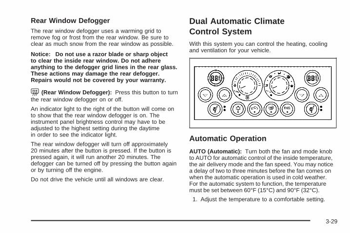
Rear Window DefoggerThe rear window defogger uses a warming grid toremove fog or frost from the rear window. Be sure toclear as much snow from the rear window as possible.
Notice: Do not use a razor blade or sharp objectto clear the inside rear window. Do not adhereanything to the defogger grid lines in the rear glass.These actions may damage the rear defogger.Repairs would not be covered by your warranty.
=(Rear Window Defogger): Press this button to turnthe rear window defogger on or off.
An indicator light to the right of the button will come onto show that the rear window defogger is on. Theinstrument panel brightness control may have to beadjusted to the highest setting during the daytimein order to see the indicator light.
The rear window defogger will turn off approximately20 minutes after the button is pressed. If the button ispressed again, it will run another 20 minutes. Thedefogger can be turned off by pressing the button againor by turning off the engine.
Do not drive the vehicle until all windows are clear.
Dual Automatic ClimateControl SystemWith this system you can control the heating, coolingand ventilation for your vehicle.
Automatic Operation
AUTO (Automatic): Turn both the fan and mode knobto AUTO for automatic control of the inside temperature,the air delivery mode and the fan speed. You may noticea delay of two to three minutes before the fan comes onwhen the automatic operation is used in cold weather.For the automatic system to function, the temperaturemust be set between 60°F (15°C) and 90°F (32°C).
1. Adjust the temperature to a comfortable setting.
3-29

2. Press the PASS. button to turn the passengerclimate control system on and off. When thepassenger system is off, the driver’s temperaturesetting is also used for the passenger and thepassenger display is off.In cold weather, the system will start at reduced fanspeeds to avoid blowing cold air into your vehicleuntil warmer air is available. The system willstart out blowing air at the floor but may changemodes automatically as the vehicle warms upto maintain the chosen temperature setting. Thelength of time needed for the air to warm upwill depend on the outside temperature and thelength of time that has elapsed since your vehiclewas last driven.
3. Wait for the system to regulate. This may take from10 to 30 minutes. Then adjust the temperature, ifnecessary.
Do not cover the solar sensor located in the center ofthe instrument panel, near the windshield. For moreinformation on the solar sensor, see “Sensors” later inthis section.
Manual Operation
xw (Temperature): To manually adjust thetemperature inside the vehicle, press the up arrow onthe temperature control to raise the temperatureand press the down arrow to lower the temperature.The display will show your selection.
When one temperature is displayed, the drivertemperature is set. When both temperatures aredisplayed, the temperature for both the driver andpassenger are set. Pressing PASS. will turn thepassenger temperature setting on and off. If only thedriver temperature is set, the driver temperature is usedfor the passenger and the passenger display is off.
9(Fan): Turn the fan knob clockwise to increase thefan speed and counterclockwise to decrease the fanspeed. Turning the fan knob cancels the automatic fanoperation and places the system in manual. Turn theknob to AUTO to return to automatic fan operation. If theairflow seems low when the fan is at the highest setting,the passenger compartment air filter, if equipped, mayneed to be replaced. See Passenger Compartment AirFilter on page 3-33 for additional information.
3-30

9 (Off): Turning the fan knob off will turn thecontroller completely off. Only the rear window defoggerand heated seats will function when the fan knob is off.
Air Flow: This control has several settings to controlthe direction of airflow.
To change the current mode, select one of the following:
AUTO: This mode is automatically set depending onthe temperature in the vehicle and solar sensorinformation.
H (Vent): This mode directs air to the instrumentpanel outlets.
% (Bi-Level): This mode directs airflow to theinstrument panel outlets and to the floor outlets. A smallamount of air is also directed to the windshield andthe side window outlets.
6 (Floor): This mode directs most of the air to thefloor outlets with some air directed to the side windowoutlets, and a little air directed to the windshield.
# (Air Conditioning): Press this button to turnthe air conditioning compressor on or off. The indicatorlight on the button will come on when the airconditioning is on.
The indicator light on the air condition button will lightevery time the vehicle is started. The air conditioner maybe turned off by pressing the air conditioner button.
? (Recirculation): Press this button to turn therecirculation mode on or off. This mode keeps outside airfrom coming in the vehicle. It can be used to preventoutside air and odors from entering your vehicle or to helpcool the air inside your vehicle more quickly.
Recirculation is not available in defrost or floor/defogmode. Pressing the recirculation button will turn on theindicator light.
Using recirculation for long periods of time may cause theair inside your vehicle to become too dry. To prevent thisfrom happening, after the air in your vehicle has cooled,turn the recirculation mode off.
z (Heated Seats): Press this button to turn theheated seats on and off. The button on the left controlsthe driver’s seat and the button on the right controlsthe passenger’s seat. See Heated Seats on page 1-3 foradditional information.
3-31
SensorsThe solar sensor on your vehicle monitors the solarradiation and the air inside of your vehicle, then uses theinformation to maintain the selected temperature byinitiating needed adjustments to the temperature, the fanspeed and the air delivery system. The system mayalso supply cooler air to the side of the vehicle facing thesun. The recirculation mode will also be activated, asnecessary. Do not cover the solar sensor located in thecenter of the instrument panel, near the windshield,or the system will not work properly.
Defogging and DefrostingFog on the inside of windows is a result of high humidity(moisture) condensing on the cool window glass. Thiscan be minimized if the climate control system isused properly. There are two modes to clear fog or frostfrom your windshield. Use the floor/defog mode toclear the windows of fog or moisture and warmthe passengers. Use defrost to remove fog or frost fromthe windshield more quickly.
- (Floor/Defog): This mode directs the air betweenthe windshield, floor outlets and side windows. Whenyou select this mode, the system turns off recirculationand runs the air-conditioning compressor unless theoutside temperature is near or below freezing. Pressingthe recirculation button, while in this mode, will haveno effect other than turning on the indicator light.
1 (Defrost): This mode directs most of the air to thewindshield, with some air directed to the side windows.In this mode, the system will automatically turn offthe recirculation and run the air conditioning compressor,unless the outside temperature is near or belowfreezing. Pressing the recirculation button, while in thismode, will have no affect other than turning on theindicator light.
Rear Window DefoggerThe rear window defogger uses a warming grid toremove fog or frost from the rear window.
The rear window defogger will only work when theengine is running.
3-32

= (Rear Window Defogger): Press this button toturn the rear window defogger on and off. Be sureto clear as much snow from the rear window as possible.
The rear window defogger will turn off approximately20 minutes after the button is pressed. If turned onagain, the defogger will only run for approximately20 minutes before turning off. The defogger can also beturned off by pressing the button again or by turningoff the engine.
Do not drive the vehicle until all the windows are clear.
Notice: Do not use anything sharp on the insideof the rear window. If you do, you could cut ordamage the warming grid, and the repairs would notbe covered by your warranty. Do not attach atemporary vehicle license, tape, a decal or anythingsimilar to the defogger grid.
Outlet AdjustmentRotate and turn the air outlets, located in the middleand at each outboard side of the instrument panel,to adjust the direction of the airflow.
Operation Tips• Clear away any ice, snow, or leaves from the air
inlets at the base of the windshield that mayblock the flow of air into the vehicle.
• Use of non-GM approved hood deflectors mayadversely affect the performance of the system.
• Keep the path under the front seats clear ofobjects to help circulate the air inside of thevehicle more effectively.
• If the airflow seems low when the fan is at thehighest setting, the passenger compartment airfilter may need to be replaced. See “PassengerCompartment Air Filter” following, for moreinformation.
Passenger Compartment Air FilterThe passenger compartment air filter is located near thepassenger’s side windshield wiper arm, underneaththe inlet grille.
The filter traps most of the pollen from entering theclimate control system. Similar to the engine’s air filter,it may need to be changed periodically to insuresystem performance. See Scheduled Maintenance onpage 6-4 for more information.
3-33

To change the passenger compartment air filter, do thefollowing:
1. Turn the ignition to ACC and the windshieldwipers on.
2. Turn the ignition to OFF when the windshieldwipers are in the upright position.
3. Raise the hood.
4. Disconnect the windshield washer pump hose fromthe fender rail and the air inlet grille.
5. Remove the hood weather-strip from thepassenger’s side of the vehicle, peeling itback halfway.
6. Remove the two air inlet grille retainers using a flattool to first pry up on the center post and then theremainder of the fastener can be pulled out.
7. Remove the air inlet grille by sliding it down todisengage the two tabs that hold it to the bottomof the windshield glass. Place the grille on thewindshield while you remove the filter. Do not try toremove the grille from the vehicle because it isstill attached on the right side by a fastener.
8. Remove the passenger compartment air filter bypulling on the tab.
9. Install a new passenger compartment air filter.Make sure it slides under the compartmentretainers. Be sure the long rubber water deflectorabove the filter stays in place.
10. Reverse steps 1 through 7.
3-34
Warning Lights, Gages, andIndicatorsThis part describes the warning lights and gages thatmay be on the vehicle. The pictures help to locate them.
Warning lights and gages can signal that something iswrong before it becomes serious enough to causean expensive repair or replacement. Paying attention tothe warning lights and gages could also save you orothers from injury.
Warning lights come on when there may be or is aproblem with one of the vehicle’s functions. As the detailsshow on the next few pages, some warning lights comeon briefly when the engine is started just to indicate theyare working. If you are familiar with this section, youshould not be alarmed when this happens.
Gages can indicate when there may be or is a problemwith one of the vehicle’s functions. Often gages andwarning lights work together to indicate when there is aproblem with the vehicle.
When one of the warning lights comes on and stays onwhile the vehicle is being driven, or when one of thegages shows there may be a problem, check the sectionthat tells you what to do about it. Follow this manual’sadvice. Waiting to do repairs can be costly – andeven dangerous. So please get to know the vehicle’swarning lights and gages. They can be a big help.
The vehicle also has a Driver Information Center (DIC)that works along with the warning lights and gages.See Driver Information Center (DIC) on page 3-52 formore information.
3-35

Instrument Panel ClusterThe instrument panel cluster is designed to show at a glance how the vehicle is running. It will show how fast thevehicle is going, about how much fuel is in the fuel tank, and many other things needed to drive the vehicle safely andeconomically.
United States version shown, Canada similar
3-36
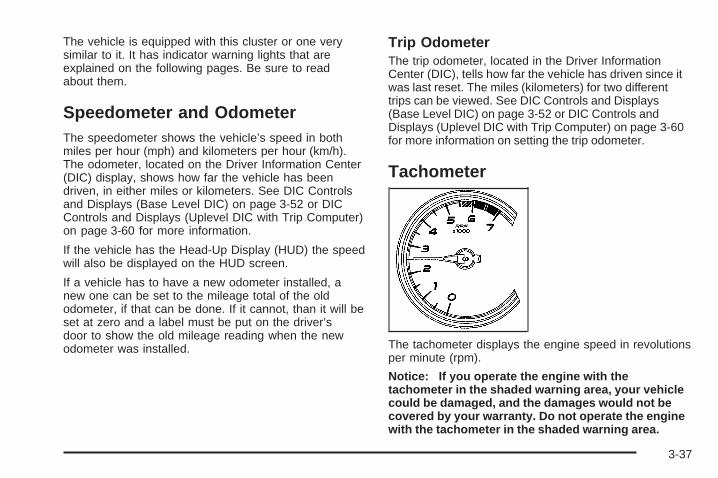
The vehicle is equipped with this cluster or one verysimilar to it. It has indicator warning lights that areexplained on the following pages. Be sure to readabout them.
Speedometer and OdometerThe speedometer shows the vehicle’s speed in bothmiles per hour (mph) and kilometers per hour (km/h).The odometer, located on the Driver Information Center(DIC) display, shows how far the vehicle has beendriven, in either miles or kilometers. See DIC Controlsand Displays (Base Level DIC) on page 3-52 or DICControls and Displays (Uplevel DIC with Trip Computer)on page 3-60 for more information.
If the vehicle has the Head-Up Display (HUD) the speedwill also be displayed on the HUD screen.
If a vehicle has to have a new odometer installed, anew one can be set to the mileage total of the oldodometer, if that can be done. If it cannot, than it will beset at zero and a label must be put on the driver’sdoor to show the old mileage reading when the newodometer was installed.
Trip OdometerThe trip odometer, located in the Driver InformationCenter (DIC), tells how far the vehicle has driven since itwas last reset. The miles (kilometers) for two differenttrips can be viewed. See DIC Controls and Displays(Base Level DIC) on page 3-52 or DIC Controls andDisplays (Uplevel DIC with Trip Computer) on page 3-60for more information on setting the trip odometer.
Tachometer
The tachometer displays the engine speed in revolutionsper minute (rpm).
Notice: If you operate the engine with thetachometer in the shaded warning area, your vehiclecould be damaged, and the damages would not becovered by your warranty. Do not operate the enginewith the tachometer in the shaded warning area.
3-37

Safety Belt Reminder LightWhen the key is turned to RUN or START, a chime willsound for several seconds to remind you and yourpassengers to buckle your safety belts. The driver safetybelt light will also come on and stay on for severalseconds, then it will flash for several more. You shouldbuckle your seat belt.
If the driver’s belt isbuckled, neither the chimenor the light will come on.
Passenger Safety BeltReminder LightSeveral seconds after the key is turned to RUN orSTART, a chime will sound for several secondsto remind the front passenger to buckle their safety belt.This would only occur if the passenger airbag isenabled. See Passenger Sensing System on page 1-61for more information. The passenger safety belt lightwill also come on and stay on for several seconds, thenit will flash for several more.
If the passenger’s safetybelt is buckled, neither thechime nor the light willcome on.
3-38
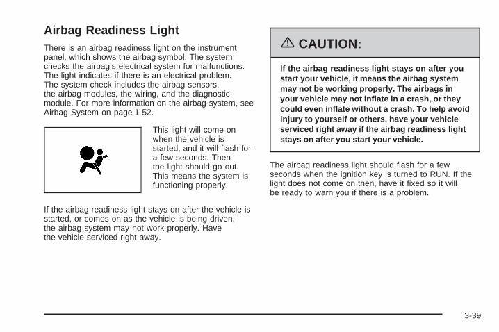
Airbag Readiness LightThere is an airbag readiness light on the instrumentpanel, which shows the airbag symbol. The systemchecks the airbag’s electrical system for malfunctions.The light indicates if there is an electrical problem.The system check includes the airbag sensors,the airbag modules, the wiring, and the diagnosticmodule. For more information on the airbag system, seeAirbag System on page 1-52.
This light will come onwhen the vehicle isstarted, and it will flash fora few seconds. Thenthe light should go out.This means the system isfunctioning properly.
If the airbag readiness light stays on after the vehicle isstarted, or comes on as the vehicle is being driven,the airbag system may not work properly. Havethe vehicle serviced right away.
{CAUTION:
If the airbag readiness light stays on after youstart your vehicle, it means the airbag systemmay not be working properly. The airbags inyour vehicle may not inflate in a crash, or theycould even inflate without a crash. To help avoidinjury to yourself or others, have your vehicleserviced right away if the airbag readiness lightstays on after you start your vehicle.
The airbag readiness light should flash for a fewseconds when the ignition key is turned to RUN. If thelight does not come on then, have it fixed so it willbe ready to warn you if there is a problem.
3-39

Passenger Airbag Status IndicatorYour vehicle has the passenger sensing system.Your instrument panel has a passenger airbagstatus indicator.
When the ignition key is turned to RUN or START, thepassenger airbag status indicator will light ON andOFF, or the symbol for on and off, for several secondsas a system check. If you use remote start to startyour vehicle from a distance (if equipped), you may notsee the system check. Then, after several moreseconds, the status indicator will light either ON or OFF,or either the on or off symbol to let you know thestatus of the right front passenger’s frontal airbag.
If the word ON or the on symbol is lit on the passengerairbag status indicator, it means that the right frontpassenger’s frontal airbag is enabled (may inflate).
{CAUTION:
If the on indicator comes on when you have arear-facing child restraint installed in the rightfront passenger’s seat, it means that thepassenger sensing system has not turned offthe passenger’s frontal airbag. A child in arear-facing child restraint can be seriouslyinjured or killed if the right front passenger’sairbag inflates. This is because the back of therear-facing child restraint would be very closeto the inflating airbag. Do not use a rear-facingchild restraint in the right front passenger’sseat if the airbag is turned on.
Your vehicle has a rear seat that will accommodate arear-facing child restraint. A label on your sun visor says,“Never put a rear-facing child seat in the front.” Thisis because the risk to the rear-facing child is so great, ifthe airbag deploys.
PassengerAirbag Status
Indicator – UnitedStates
PassengerAirbag Status
Indicator – Canada
3-40

{CAUTION:
Even though the passenger sensing system isdesigned to turn off the passenger’s frontalairbag if the system detects a rear-facing childrestraint, no system is failsafe, and no one canguarantee that an airbag will not deploy undersome unusual circumstance, even though it isturned off. We recommend that rear-facingchild restraints be secured in the rear seat,even if the airbag is off.
If the word OFF or the off symbol is lit on the airbagstatus indicator, it means that the passenger sensingsystem has turned off the right front passenger’s frontalairbag. See Passenger Sensing System on page 1-61for more on this, including important safety information.
If, after several seconds, all status indicator lightsremain on, or if there are no lights at all, there may be aproblem with the lights or the passenger sensingsystem. See your dealer for service.
{CAUTION:
If the off indicator and the airbag readinesslight ever come on together, it means thatsomething may be wrong with the airbagsystem. If this ever happens, have the vehicleserviced promptly, because an adult-sizeperson sitting in the right front passenger seatmay not have the protection of the frontalairbag. See Airbag Readiness Light onpage 3-39.
3-41

Up-Shift Light
This symbol can appear onthe instrument panel if thevehicle has a V8 orsupercharged engine andthe shift lever is in themanual transaxle position.
It will appear as a prompt to up-shift to the next gearusing one of the Tap-Shift® paddles located on thesteering wheel.
If equipped, this symbol will appear on the Head UpDisplay (HUD) only.
See Automatic Transaxle Operation on page 2-25 andHead-Up Display (HUD) on page 3-21 for moreinformation.
Brake System Warning LightThe vehicle’s hydraulic brake system is divided intotwo parts. If one part is not working, the other part canstill work and stop the vehicle. For good braking,though, both parts should be working well.
This light should come on briefly when the ignition key isturned to RUN. If it does not come on then, have it fixedso it will be ready to warn you if there is a problem.
United States Canada
3-42

When the ignition is on, the brake system warning lightwill also come on when the parking brake is set.The light will stay on if the parking brake does notrelease fully. If it stays on after the parking brake is fullyreleased, it means the vehicle has a brake problem.
The PARKING BRAKE ON message will also appear inthe Driver Information Center (DIC) when the parkingbrake is set and the vehicle is going faster than 5 mph.See DIC Warnings and Messages on page 3-72 formore information.
The brake warning light may also come on when thebrake fluid is low. If this occurs, the LOW BRAKE FLUIDmessage will also appear in the Driver InformationCenter (DIC). See DIC Warnings and Messageson page 3-72 for more information.
If the brake warning light comes on while the vehicle isbeing driven, pull off the road and stop carefully.The brake pedal may be harder to push, or it may gocloser to the floor. It may also take the vehicle longer tostop. If the light is still on, have the vehicle towed forservice. See Towing Your Vehicle on page 4-38.
{CAUTION:
Your brake system may not be workingproperly if the brake system warning light is on.Driving with the brake system warning light oncan lead to an accident. If the light is still onafter you have pulled off the road and stoppedcarefully, have the vehicle towed for service.
3-43

Anti-Lock Brake SystemWarning Light
If the vehicle has theAnti-lock Brake System(ABS), this light will comeon when the engine isstarted and may stay onfor several seconds.That is normal.
If the ABS warning light comes on and stays on, theremay be a problem with the anti-lock portion of the brakesystem. If the brake system warning light is not on,the vehicle still has brakes, but it does not have anti-lockbrakes. See Brake System Warning Light on page 3-42.
If the light stays on, the vehicle needs service. If thelight comes on while the vehicle is being driven, stop assoon as possible and turn the ignition off. Then startthe vehicle again to reset the system. If the lightstill stays on, or comes on again while driving, thevehicle needs service. If the regular brake systemwarning light is not on, the vehicle still has brakes, but itdoes not have anti-lock brakes. If the brake systemwarning light is also on, the vehicle does not haveanti-lock brakes and there is a problem with the regularbrakes. See Brake System Warning Light on page 3-42.If both the brake system warning light and the anti-lockbrake system light is on, pull off the road and havethe vehicle towed for service.
The anti-lock brake system warning light will come onbriefly when the ignition key is turned to RUN. Thisis normal. If the light does not come on then, have itfixed so it will be ready to warn you if there is a problem.
3-44

Traction Control System (TCS)Warning Light
If the vehicle has the3800 supercharged V6engine or the 5300 V8engine and the TractionControl System (TCS), thislight may come on for thefollowing reasons:
• The Traction Control button, located on the centerconsole, is pressed, turning the system off. The lightwill stay on. To turn the system back on, press thebutton again and the warning light should go out. SeeTraction Control System (TCS) on page 4-9 for moreinformation.
• If there is a brake system problem that is specificallyrelated to traction control, the TCS will turn off andthe warning light will come on.
• If the brakes begin to overheat, the TCS will turn offand the warning light will come on until the brakescool down.
If the traction control system warning light comes onand stays on for an extended period of time when thesystem is turned on, the vehicle needs service.
Enhanced Traction SystemWarning Light
If the vehicle is equippedwith the EnhancedTraction System (ETS),this light may come on forthe following reasons:
• If the Traction Control button located on the centerconsole is pressed, turning the system off. Thislight will come on and stay on. To turn the systemback on, press the button again and the warninglight should turn off. See Enhanced Traction System(ETS) on page 4-11.
• If the system is affected by an engine-relatedproblem, the system will turn off and the warninglight will come on.
If the light comes on and stays on for an extendedperiod of time when the system is turned on, the vehicleneeds service.
3-45
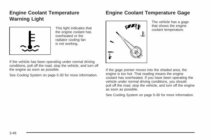
Engine Coolant TemperatureWarning Light
This light indicates thatthe engine coolant hasoverheated or theradiator cooling fanis not working.
If the vehicle has been operating under normal drivingconditions, pull off the road, stop the vehicle, and turn offthe engine as soon as possible.
See Cooling System on page 5-30 for more information.
Engine Coolant Temperature Gage
The vehicle has a gagethat shows the enginecoolant temperature.
If the gage pointer moves into the shaded area, theengine is too hot. That reading means the enginecoolant has overheated. If you have been operating thevehicle under normal driving conditions, you shouldpull off the road, stop the vehicle, and turn off the engineas soon as possible.
See Cooling System on page 5-30 for more information.
3-46
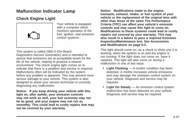
Malfunction Indicator Lamp
Check Engine LightYour vehicle is equippedwith a computer whichmonitors operation of thefuel, ignition, and emissioncontrol systems.
This system is called OBD II (On-BoardDiagnostics-Second Generation) and is intended toassure that emissions are at acceptable levels for thelife of the vehicle, helping to produce a cleanerenvironment. The check engine light comes on toindicate that there is a problem and service is required.Malfunctions often will be indicated by the systembefore any problem is apparent. This may prevent moreserious damage to your vehicle. This system is alsodesigned to assist your service technician in correctlydiagnosing any malfunction.
Notice: If you keep driving your vehicle with thislight on, after awhile, your emission controlsmay not work as well, your fuel economy may notbe as good, and your engine may not run assmoothly. This could lead to costly repairs that maynot be covered by your warranty.
Notice: Modifications made to the engine,transaxle, exhaust, intake, or fuel system of yourvehicle or the replacement of the original tires withother than those of the same Tire PerformanceCriteria (TPC) can affect your vehicle’s emissioncontrols and may cause this light to come on.Modifications to these systems could lead to costlyrepairs not covered by your warranty. This mayalso result in a failure to pass a required EmissionInspection/Maintenance test. See Accessoriesand Modifications on page 5-3.
This light should come on, as a check to show you it isworking, when the ignition is on and the engine isnot running. If the light does not come on, have itrepaired. This light will also come on during amalfunction in one of two ways:
• Light Flashing — A misfire condition has beendetected. A misfire increases vehicle emissionsand may damage the emission control system onyour vehicle. Diagnosis and service may berequired.
• Light On Steady — An emission control systemmalfunction has been detected on your vehicle.Diagnosis and service may be required.
3-47

If the Light is FlashingThe following may prevent more serious damage toyour vehicle:
• Reducing vehicle speed
• Avoiding hard accelerations
• Avoiding steep uphill grades
• If you are towing a trailer, reduce the amount ofcargo being hauled as soon as it is possible
If the light stops flashing and remains on steady, see “Ifthe Light Is On Steady” following.
If the light continues to flash, when it is safe to do so,stop the vehicle. Find a safe place to park your vehicle.Turn the key off, wait at least 10 seconds and restartthe engine. If the light remains on steady, see “Ifthe Light Is On Steady” following. If the light is stillflashing, follow the previous steps, and see your dealerfor service as soon as possible.
If the Light Is On SteadyYou may be able to correct the emission systemmalfunction by considering the following:
Did you recently put fuel into your vehicle?
If so, reinstall the fuel cap, making sure to fully installthe cap. See Filling the Tank on page 5-7. Thediagnostic system can determine if the fuel cap hasbeen left off or improperly installed. A loose or missingfuel cap will allow fuel to evaporate into the atmosphere.A few driving trips with the cap properly installedshould turn the light off.
Did you just drive through a deep puddle of water?
If so, your electrical system may be wet. The conditionwill usually be corrected when the electrical systemdries out. A few driving trips should turn the light off.
3-48
Have you recently changed brands of fuel?
If so, be sure to fuel your vehicle with quality fuel. SeeGasoline Octane on page 5-5. Poor fuel quality willcause your engine not to run as efficiently as designed.You may notice this as stalling after start-up, stallingwhen you put the vehicle into gear, misfiring, hesitationon acceleration, or stumbling on acceleration. (Theseconditions may go away once the engine is warmed up.)This will be detected by the system and cause thelight to turn on.
If you experience one or more of these conditions,change the fuel brand you use. It will require at leastone full tank of the proper fuel to turn the light off.
If none of the above steps have made the light turn off,your dealer can check the vehicle. Your dealer hasthe proper test equipment and diagnostic tools to fix anymechanical or electrical problems that may havedeveloped.
Emissions Inspection andMaintenance ProgramsSome state/provincial and local governments have ormay begin programs to inspect the emission controlequipment on your vehicle. Failure to pass thisinspection could prevent you from getting a vehicleregistration.
Here are some things you need to know to help yourvehicle pass an inspection:
Your vehicle will not pass this inspection if the checkengine light is on or not working properly.
Your vehicle will not pass this inspection if the OBD(on-board diagnostic) system determines that criticalemission control systems have not been completelydiagnosed by the system. The vehicle would beconsidered not ready for inspection. This can happen ifyou have recently replaced your battery or if yourbattery has run down. The diagnostic system isdesigned to evaluate critical emission control systemsduring normal driving. This may take several daysof routine driving. If you have done this and your vehiclestill does not pass the inspection for lack of OBDsystem readiness, your GM dealer can prepare thevehicle for inspection.
3-49
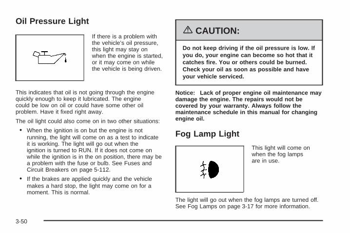
Oil Pressure Light
If there is a problem withthe vehicle’s oil pressure,this light may stay onwhen the engine is started,or it may come on whilethe vehicle is being driven.
This indicates that oil is not going through the enginequickly enough to keep it lubricated. The enginecould be low on oil or could have some other oilproblem. Have it fixed right away.
The oil light could also come on in two other situations:
• When the ignition is on but the engine is notrunning, the light will come on as a test to indicateit is working. The light will go out when theignition is turned to RUN. If it does not come onwhile the ignition is in the on position, there may bea problem with the fuse or bulb. See Fuses andCircuit Breakers on page 5-112.
• If the brakes are applied quickly and the vehiclemakes a hard stop, the light may come on for amoment. This is normal.
{CAUTION:
Do not keep driving if the oil pressure is low. Ifyou do, your engine can become so hot that itcatches fire. You or others could be burned.Check your oil as soon as possible and haveyour vehicle serviced.
Notice: Lack of proper engine oil maintenance maydamage the engine. The repairs would not becovered by your warranty. Always follow themaintenance schedule in this manual for changingengine oil.
Fog Lamp Light
This light will come onwhen the fog lampsare in use.
The light will go out when the fog lamps are turned off.See Fog Lamps on page 3-17 for more information.
3-50
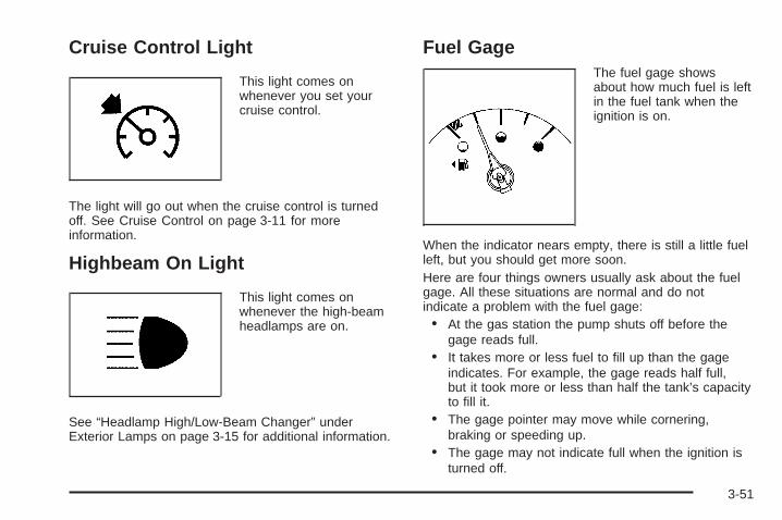
Cruise Control Light
This light comes onwhenever you set yourcruise control.
The light will go out when the cruise control is turnedoff. See Cruise Control on page 3-11 for moreinformation.
Highbeam On Light
This light comes onwhenever the high-beamheadlamps are on.
See “Headlamp High/Low-Beam Changer” underExterior Lamps on page 3-15 for additional information.
Fuel GageThe fuel gage showsabout how much fuel is leftin the fuel tank when theignition is on.
When the indicator nears empty, there is still a little fuelleft, but you should get more soon.Here are four things owners usually ask about the fuelgage. All these situations are normal and do notindicate a problem with the fuel gage:• At the gas station the pump shuts off before the
gage reads full.• It takes more or less fuel to fill up than the gage
indicates. For example, the gage reads half full,but it took more or less than half the tank’s capacityto fill it.
• The gage pointer may move while cornering,braking or speeding up.
• The gage may not indicate full when the ignition isturned off.
3-51
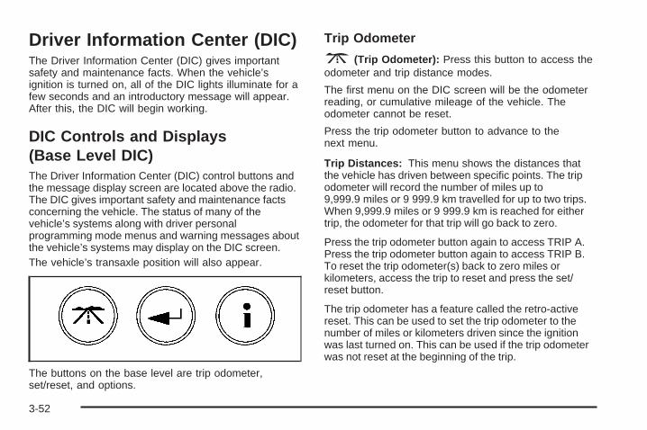
Driver Information Center (DIC)The Driver Information Center (DIC) gives importantsafety and maintenance facts. When the vehicle’signition is turned on, all of the DIC lights illuminate for afew seconds and an introductory message will appear.After this, the DIC will begin working.
DIC Controls and Displays(Base Level DIC)The Driver Information Center (DIC) control buttons andthe message display screen are located above the radio.The DIC gives important safety and maintenance factsconcerning the vehicle. The status of many of thevehicle’s systems along with driver personalprogramming mode menus and warning messages aboutthe vehicle’s systems may display on the DIC screen.The vehicle’s transaxle position will also appear.
The buttons on the base level are trip odometer,set/reset, and options.
Trip Odometer
3 (Trip Odometer): Press this button to access theodometer and trip distance modes.
The first menu on the DIC screen will be the odometerreading, or cumulative mileage of the vehicle. Theodometer cannot be reset.
Press the trip odometer button to advance to thenext menu.
Trip Distances: This menu shows the distances thatthe vehicle has driven between specific points. The tripodometer will record the number of miles up to9,999.9 miles or 9 999.9 km travelled for up to two trips.When 9,999.9 miles or 9 999.9 km is reached for eithertrip, the odometer for that trip will go back to zero.
Press the trip odometer button again to access TRIP A.Press the trip odometer button again to access TRIP B.To reset the trip odometer(s) back to zero miles orkilometers, access the trip to reset and press the set/reset button.
The trip odometer has a feature called the retro-activereset. This can be used to set the trip odometer to thenumber of miles or kilometers driven since the ignitionwas last turned on. This can be used if the trip odometerwas not reset at the beginning of the trip.
3-52

To use the retro-active reset feature, press and hold theset/reset button for at least three seconds. The tripodometer will display the number of miles or kilometersdriven since the ignition was last turned on and thevehicle began moving. Once the vehicle has begunmoving, the trip odometer will accumulate mileage. Forexample, if the vehicle was driven 5.0 miles (8.0 km)before the vehicle is started again, and then theretro-active reset feature is activated, the display willshow 5.0 miles (8.0 km). As the vehicle begins moving,the display will increase to 5.1 miles (8.2 km), 5.2 miles(8.4 km), etc.
If the retro-active reset feature is activated after thevehicle is started, but before it begins moving, the displaywill show the number of miles or kilometers that weredriven during the last ignition cycle.
Press the trip odometer button again to accessthe odometer.
Set/Reset
r (Set/Reset): Press this button to set or reseta menu item when using the trip odometer oroptions buttons.
Options
4 (Options): Press this button to access the Date,Language, Display Units, Daytime DisplayEnhancements, Engine Oil Monitor System, Tire InflationMonitor System, and Personal Programming modes.
Date: This menu sets the date.
The time is set through the radio. See Setting the Timeon page 3-96 for more information.
To set the date, use the following procedure:
1. Press the options button until the date is displayedon the DIC.
2. Press the set/reset button to access the RESETYEAR screen. The second position in the yearwill be selected. Press and hold the set/reset buttonto scroll through the available digits. Release thebutton when the correct digit appears.
3. Press the options button to advance to the firstposition in the year. Press and hold the set/resetbutton to scroll through the available digits. Releasethe button when the correct digit appears.
4. Press the options button to advance to the monthsof the year.
3-53

5. Press the set/reset button to scroll through themonths of the year, releasing the button whenthe correct month appears.
6. Press the options button to advance to the days ofthe month.
7. Press the set/reset button to scroll through the daysof the month, releasing the button when the correctday appears.
8. Press the options button again to advance to themain date screen. The screen will now display thenew date.
Language: This menu allows the selection of thelanguage in which the DIC messages will appear. TheDIC can be programmed to one of three languages:English, French or Spanish. The message on the HUD,if equipped, will also appear in the language selected.See Head-Up Display (HUD) on page 3-21.
To change the language, use the following procedure:
1. Press the options button to enter thelanguage screen.
2. Press the set/reset button to scroll through and setthe language choice.
3. Press the options button again to advance to thenext screen.
Display Units: This menu allows selection ofmeasurements to be displayed in English or metricunits. The messages on the HUD, if equipped, and theinstrument panel cluster will also appear with thetype of measurement selected.
To set the measurement when Display Units is shown,use the following procedure:
1. Press the set/reset button to select ENGLISHor METRIC.
2. Press the options button again to advance to thenext screen.
DAYTIME DISPLAY ENHANCEMENTS: This menuallows selection of the color of the display message.When ON is selected for the daytime enhancement, themessages will appear black on a red screen. Thiscombination makes it easier to see the DIC messagesduring the daytime. When OFF is selected, or whenthe headlamps are on, the messages will appear red ona black background.
To set the daytime display enhancements, use thefollowing procedure:
1. Press the set/reset button to select OFF or ON.
2. Press the options button again to advance tothe next screen.
3-54
ENGINE OIL MONITOR SYSTEM: This menu allowsthe engine oil monitor system to be reset. To resetthe engine oil monitor system, see Engine Oil LifeSystem on page 5-19.
Tire Inflation Monitor System: If the vehicle has ABS,this menu sets the tire inflation monitor system. See “TireInflation Monitor System” under Inflation - Tire Pressureon page 5-67 for more information.
To set or reset the tire inflation monitor system, use thefollowing procedure:
1. Press the set/reset button to reset the tire inflationmonitor system. The message, TIRE INFLATIONHAS BEEN SET, will appear on the screen ifthe Check Tire Pressure message, indicating anirregularity in the pressure of one of the tires,had previously appeared on the DIC. If the CheckTire Pressure message did not appear and theset/reset button is pressed, the system will reset,but no acknowledgment message will appear on thescreen.
2. Press the options button again to advance to thenext screen.
Select the set/reset button to return to themain (date) screen.
PERSONAL PROGRAMMING MODE: This menuallows you to customize several features on yourvehicle. These adjustments can only be made while thevehicle is in PARK (P). Press the set/reset button todisplay the first screen.
Personal Programming Mode ScreensPress the options button to access these modes:
EXTERIOR LIGHTING DELAY: This screen allows thisfeature to be turned off or allows the selection of thenumber of seconds the headlamps, sidelamps, taillamps,fog lamps, and back-up lamps are turned on after thekey is removed from the ignition, or the vehicle isunlocked using the remote keyless entry transmitter.
If OFF is selected, the exterior lamps will not turn on.
If a time delay is chosen, the lamps will turn on forthe selected time. The time delay will be cancelled andthe exterior lamps will turn on automatically whenthe key is removed from the ignition, or the vehicle isunlocked using the remote keyless entry transmitter.
To program this mode, use the following procedure:
1. Press and release the set/reset button to scroll tothe selection to be programmed. Choose fromOFF, 15, 30, 60, or 90 seconds.
2. Press the options button again to advance to thenext screen.
3-55

INTERIOR LIGHTS WHEN DOOR CLOSED: Thisscreen allows this feature to be turned OFF or ON.
If OFF is selected, the interior lamps will turn offimmediately when the ignition is turned off and the lastdoor is closed.
If ON is selected, the interior lamps will stay on forabout 25 seconds after the vehicle’s ignition is turned offand the last door is closed.
To program this mode, use the following procedure:
1. Press and release the set/reset button to scroll toeither OFF or ON.
2. Press the options button again to advance to thenext screen.
INTERIOR LIGHTS WHEN KEY REMOVED: Thisscreen allows this feature to be turned OFF or ON. Thisfeature enables the interior lamps in the vehicle toturn on for about 25 seconds after the key is removedfrom the ignition.
If OFF is selected, removing the key from the ignitionwill not cause the interior lamps to turn on.
If ON is selected, removing the key from the ignition willcause the interior lamps to be turned on for about25 seconds.
To program this mode, use the following procedure:
1. Press and release the set/reset button to scroll toeither OFF or ON.
2. Press the options button again to advance to thenext screen.
AUTO DOOR LOCK: This screen allows this feature tobe turned OFF or ON.
If OFF is selected, all automatic door locking is disabled.The doors will always need to be locked manuallybefore driving, to increase occupant safety.
If ON is selected, the vehicle’s doors automatically lockwhen the doors are closed and the vehicle is shiftedinto DRIVE (D).
To program this mode, use the following procedure:
1. Press and release the set/reset button to scroll toeither OFF or ON.
2. Press the options button again to advance to thenext screen.
AUTO DOOR UNLOCK: This screen can be used ifON was selected for the AUTO DOOR LOCK feature.This screen allows this feature to be turned off, used forthe driver’s door only, or for all the doors.
If OFF is selected, none of the doors will unlock whenthe vehicle’s transaxle is shifted into PARK (P).
3-56

If DRIVER is selected, only the driver’s door will unlockwhen the vehicle’s transaxle is shifted into PARK (P).
If ALL is selected, all the doors will unlock whenthe vehicle’s transaxle is shifted into PARK (P).
To program this mode, use the following procedure:1. Press and release the set/reset button to scroll to
either OFF, DRIVER, or ALL.2. Press the options button again to advance to the
next screen.
AUTO DOOR UNLOCK ON: If DRIVER or ALL wasselected on the AUTO DOOR UNLOCK screen,this screen allows selection of when the vehicle’s doorswill unlock. The choices are when the key is removedfrom the ignition or when the vehicle is shifted intoPARK (P).
If KEY-OUT is selected, the auto door unlock willfunction when the key is taken out of the ignition.
If PARK is selected, the auto door unlock will functionwhen the transaxle is shifted into PARK (P).
To program this mode, use the following procedure:
1. Press and release the set/reset button to scroll toeither KEY-OUT or PARK.
2. Press the options button again to advance to thenext screen.
DELAYED LOCKING: This screen allows this featureto be turned OFF or ON. The key must be out ofthe ignition for this feature to work.
If OFF is selected, there will be no delayed locking ofthe vehicle’s doors.
If ON is selected, the locking of the vehicle’s doors willbe delayed by five seconds after a power door lockswitch is pressed when a door is open, or the LOCKbutton on the remote keyless entry transmitter ispressed while a door is open.
To program this mode, use the following procedure:
1. Press and release the set/reset button to scroll toeither OFF or ON.
2. Press the options button again to advance to thenext screen.
REMOTE LOCKS FEEDBACK: This screen allowsselection for this option to be turned OFF, or gives thechoice of two methods of verification; LIGHTS orLIGHTS and HORN; that indicate the vehicle’s doorsare locked when the LOCK button on the remote keylessentry transmitter is pressed.
If OFF is selected, this feature will not be programmed.
If LIGHTS is selected, the exterior lamps will flashwhen the LOCK button on the remote keyless entrytransmitter is pressed.
3-57

If LIGHTS and HORN are selected, the exterior lampswill flash when the LOCK button on the remotekeyless entry transmitter is pressed and the horn willsound when the LOCK button on the remote keylessentry transmitter is pressed again within five seconds ofthe previous command.
To program this mode, use the following procedure:
1. Press the set/reset button to scroll to OFF, LIGHTS,or LIGHTS and HORN.
2. Press the options button again to advance to thenext screen.
If the vehicle does not have a content theft-deterrentsystem, the next screens with PROGRAMMINGFINISHED and DISPLAY OFF will appear.
If the vehicle does have a content theft-deterrentsystem, the next screen will appear.
THEFT DETERRENT: The vehicle may have a contenttheft-deterrent system. Once it is turned on, thesystem will activate if someone tries to enter the vehiclewithout using the remote keyless entry transmitter orthe correct key. This screen allows this feature tobe turned OFF or ON.
If OFF is selected, the theft-deterrent system will notfunction.
If ON is selected, the theft-deterrent system will beactivated.
To program this mode, use the following procedure:
1. Press the set/reset button to scroll to OFF or ON.
2. Press the options button again to advance tothe next screen.
KEY CYLINDER DISARM: If the vehicle has a contenttheft-deterrent system, this screen allows this featureto be turned OFF or ON.
If OFF is selected, the content theft-deterrent systemwill not disarm when the vehicle is unlocked usingthe door lock, or when someone tampers with thedoor lock.
If ON is selected, the content theft-deterrent systemwill disarm when the vehicle is unlocked using the doorkey. This makes the vehicle more resistant to keylock tampering.
To program this mode, use the following procedure:
1. Press the set/reset button to scroll to OFF or ON.
2. Press the options button again to advance tothe next screen.
3-58

LOCK SWITCH ARM: If the vehicle has the contenttheft-deterrent system and ON was selected onthe THEFT DETERRENT screen, this screen allows thisfeature to be turned OFF or ON. If ON is selected,the content theft-deterrent system starts the armingprocess when a door lock switch is pressed while adoor is open.
If OFF is selected, the theft-deterrent system will notactivate this feature.
If ON is selected, the content theft-deterrent system willarm when the doors are locked with the door lockswitch. The key must be removed from the ignition whenthe doors are locked or the content theft-deterrentsystem will not arm.
To program this mode, use the following procedure:
1. Press the set/reset button to scroll to OFF or ON.
2. Press the options button again to advance tothe next screen.
REMOTE START: If your vehicle has the remote startfeature, this screen allows this feature to be turnedOFF or ON. The remote start feature allows you to startthe engine from outside of the vehicle using yourremote keyless entry transmitter. See “Remote VehicleStart” under Remote Keyless Entry System Operationon page 2-4 for more information.
If OFF is selected, the remote start feature willbe disabled.
If ON is selected, the remote start feature willbe enabled.
To program this mode, use the following procedure:
1. Press the set/reset button to scroll to OFF or ON.
2. Press the options button again to advance tothe next screen.
PROGRAMMING FINISHED will appear on the nextscreen. This confirms that the personal optionsprogramming is complete.
DISPLAY OFF will appear on the next screen. Thescreen will count down and then go blank. Press theoptions button to advance to a new screen.
3-59

DIC Controls and Displays (UplevelDIC with Trip Computer)The Driver Information Center (DIC) control buttons andthe message display screen are located above theradio. The DIC gives important safety and maintenancefacts concerning the vehicle. The status of many ofthe vehicle’s systems along with driver personalizationmenus and warning messages about the vehicle’ssystems may display on the DIC screen.
The outside temperature automatically appears on thebottom right corner of the DIC display screen. If theoutside temperature is below 38°F (3°C), the temperaturereading will toggle between displaying the outsidetemperature and the word ICE for two minutes. If there isa problem with the system that controls the temperaturedisplay, the letters OC (Open Circuit) or SC (ShortCircuit) will appear on the display. If this occurs, have thevehicle serviced byyour GM dealer.
The vehicle’s transaxle position and the direction thevehicle is traveling will also appear on the DIC screen.
The compass is self-calibrating, which eliminates theneed to manually set the compass. However, undercertain circumstances, such as during a long distancecross-country trip, it will be necessary to compensate forcompass variance and reset the zone through theDIC. See “Setting the Compass” later in this section formore information.
The buttons on the DIC trip computer are gages, tripodometer, set/reset, options, and fuel.
Gages
2 (Gages): Press this button to access the OIL LIFEREMAINING, TRANSMISSION FLUID TEMPERATURE,BATTERY, ENGINE HOURS, ENGINE BOOST, andMAXIMUM Gs modes.
3-60

OIL LIFE REMAINING: Press the gages button untilOIL LIFE REMAINING is displayed. This screenindicates the percentage of oil life in the vehicle’s enginethat has not degraded. See Engine Oil on page 5-16for more information.
After the oil has been changed in the vehicle, reset theENGINE OIL MONITOR screen in the options menu.To reset the engine oil monitor system, see Engine OilLife System on page 5-19.
Press the gages button again to advance to thenext screen.
TRANSMISSION FLUID TEMP: This screen displaysthis message along with the temperature (F° or C°)of the transmission fluid.
Press the gages button again to advance to the nextscreen.
BATTERY: This screen displays the amount of voltsthe battery is generating.
Your vehicle’s charging system regulates voltage basedon the state of the battery. The battery voltage mayfluctuate when viewing this information on the DIC. Thisis normal.
Press the gages button again to advance to thenext screen.
ENGINE HOURS: This screen shows the number ofcumulative hours the engine has operated while the keywas in the RUN position. This screen cannot be reset.
Press the gages button to scroll to the next screen.
ENGINE BOOST: If the vehicle has the superchargedengine, this screen will appear. It shows a graphicthat indicates the amount of boost the engine isreceiving.
Press the gages button again to scroll to thenext screen.
MAXIMUM Gs: If you have the GXP option, this screenwill appear. The DIC monitors and keeps track of themaximum levels for acceleration, deceleration, andlateral-acceleration achieved since the screen was lastreset. If you try to select this screen while the vehicleis moving, the message MAXIMUM Gs NOTAVAILABLE WHILE MOVING will display. To view themaximum accelerations achieved since last reset,you must bring the vehicle to a stop. Then the valueswill be displayed. To reset the values to zero, press andhold the set/reset button.
Press the gages button again to scroll to thenext screen.
3-61
Trip Odometer
3 (Trip Odometer): Press this button to access theOdometer, Trip Distances, AVERAGE SPEED, andTIME ELAPSED modes.
Odometer: When the trip odometer button is pressed,the first menu displayed on the DIC screen is theodometer reading, or cumulative mileage of the vehicle.The odometer cannot be reset.
Press the trip odometer button again to advance to thenext menu.
Trip Distances: This menu shows the distances thatthe vehicle has driven between specific points. Thetrip odometer will record the number of miles upto 9,999.9 miles or 9 999.9 km travelled for up totwo trips. When 9,999.9 miles or 9 999.9 km is reachedfor either trip, the odometer for that trip will go backto zero.
To reset the trip distances, use the following procedures:
1. Press the trip odometer button again to accessTRIP A. Press the trip odometer button again toaccess TRIP B. To reset the trip odometer(s) back tozero miles or to zero kilometers, access the trip thatneeds to be reset and press the set/reset button.
2. Press the trip odometer button again to accessthe odometer.
The trip odometer has a feature called the retro-activereset. This can be used to set the trip odometer tothe number of miles (kilometers) driven since the ignitionwas last turned on. This can be used if the tripodometer is not reset at the beginning of the trip.
To use the retro-active reset feature, press and hold theset/reset button for at least three seconds. The tripodometer will display the number of miles or kilometersdriven since the ignition was last turned on and thevehicle was moving. Once the vehicle begins moving,the trip odometer will accumulate mileage. For example,if the vehicle was driven 5.0 miles (8.0 km) before itis started again, and then the retro-active reset featureis activated, the display will show 5.0 miles (8.0 km).As the vehicle begins moving, the display will thenincrease to 5.1 miles (8.2 km), 5.2 miles (8.4 km), etc.
If the retro-active reset feature is activated after thevehicle is started, but before it begins moving, thedisplay will show the number of miles or kilometers thatwere driven during the last ignition cycle.
Average Speed: The average speed is displayed inmiles per hour (mph) or kilometers per hour (km/h). Theaverage speed is calculated from the various vehiclespeeds recorded since the last reset of this menu item.To reset the average speed, press the set/resetbutton. The display will return to zero.
Press the trip odometer button again to advance to thenext screen.
3-62
Time Elapsed: This screen can be used as astopwatch. The display can show the hours, minutesand seconds. The elapsed time indicator will record upto 99 hours, 59 minutes and 59 seconds, then it willreset to zero and continue counting.
To set the time elapsed function, use the followingprocedures:
1. Press the set/reset button for less than two secondsto start or stop the timer.
2. Press and hold the set/reset button for more thantwo seconds to reset the timer back to zero.
Set/Reset
r (Set/Reset): Press this button to set or reset amode item when using the trip odometer or optionbuttons.
Options
4 (Options): Press this button to access the Date,Language, Display Units, Daytime DisplayEnhancements, Engine Oil Monitor System, TireInflation Monitor System, Compass Calibration, and thePersonal Programming modes.
Date: This menu sets the date.
The time is set through the radio. See Setting the Timeon page 3-96 for more information.
To set the date, use the following procedure:
1. Press the options button until the date is displayedon the DIC.
2. Press the set/reset button to access the RESETYEAR screen. The second position in the yearwill be selected. Press and hold the set/reset buttonto scroll through the available digits. Release thebutton when the correct digit appears.
3. Press the options button to advance to the firstposition in the year. Press and hold the set/resetbutton to scroll through the available digits. Releasethe button when the correct digit appears.
4. Press the options button to advance to the monthsof the year.
5. Press the set/reset button to scroll through themonths of the year, releasing the button whenthe correct month appears.
6. Press the options button to advance to the days ofthe month.
7. Press the set/reset button to scroll through the daysof the month, releasing the button when the correctday appears.
8. Press the options button again to advance to themain date screen. The screen will now display thenew date.
3-63
Language: This menu allows selection of the languagein which the DIC messages will appear. The DIC canbe programmed in one of three languages: English,French, or Spanish. The message on the HUD, ifequipped, will also appear in the language selected.See Head-Up Display (HUD) on page 3-21.
To change the language, use the following procedure:
1. Press the options button to enter thelanguage screen.
2. Press the set/reset button to scroll through and setthe language choice.
3. Press the options button again to advance to thenext screen.
Display Units: This menu allows selection ofmeasurements to be displayed in English or metricunits. The messages on the HUD, if equipped, and theinstrument panel cluster will also appear in the typeof measurement selected.
To set the display units function, use the followingprocedure:
1. Press the set/reset button to select ENGLISHor METRIC.
2. Press the options button to advance to thenext screen.
DAYTIME DISPLAY ENHANCEMENTS: This menuallows selection of the color of the display message.When ON is selected for the daytime enhancement, themessages will appear black on a red screen. Thiscombination makes it easier to see the DIC messagesduring the daytime. When OFF is selected, or whenthe headlamps are on, the messages will appear red ona black background.
To set the daytime display enhancements function, usethe following procedure:
1. Press the set/reset button to select OFF or ON.
2. Press the options button to advance to thenext screen.
ENGINE OIL MONITOR SYSTEM: This menu allowsthe engine oil monitor system to be reset. To resetthe engine oil monitor system, see Engine Oil LifeSystem on page 5-19.
Tire Inflation Monitor System: If the vehicle has ABS,this menu allows the tire inflation monitor system tobe reset. See “Tire Inflation Monitor System” underInflation - Tire Pressure on page 5-67 for moreinformation.
3-64

To set or reset the tire inflation monitor system, use thefollowing procedures:
1. Press the set/reset button to reset the tire inflationmonitor system. TIRE INFLATION HAS BEEN SETwill appear on the screen If the “Check TirePressure” message, indicating an irregularity in thepressure of one of the tires, had previouslyappeared on the DIC. If the “Check Tire Pressure”message did not appear, and the set/resetbutton is pressed, the system will reset, but noacknowledgment message will appear onthe screen.
2. Press the options button again to advance to thenext screen.Select the set/reset button to return to the main(date) screen.
COMPASS CALIBRATION MODE: This menu allowsyou to adjust for compass variance.
Setting the CompassThe compass is self-calibrating, which eliminates theneed to manually set the compass.
However, under certain circumstances, such as during along distance cross-country trip, it will be necessaryto compensate for compass variance and reset the zonethrough the DIC.
Compass variance is the difference between the earth’smagnetic north and true geographic north. If notadjusted to account for compass variance, the compassin the vehicle could give false readings.
In order to do this, the compass must be set orcalibrated to the variance zone in which the vehicleis travelling.
3-65

To adjust for compass variance, use the followingprocedure:
1. Find the vehicle’s current location and variancezone number on the map.
2. Press the set/reset button to scroll through andselect the appropriate variance zone.
3. Press the options button to advance to thecalibration screen.
4. Drive the vehicle in a circle two times to activatethe compass.
The direction the vehicle is moving will be displayed inthe bottom left corner of the screen, and will appearin the gages, fuel, trip, and some of the options modes.
Press the options button again to advance to thenext screen.
Personal Programming Mode Screens
PERSONAL PROGRAMMING MODE: This menuallows you to customize several features on yourvehicle. These adjustments can only be made while thevehicle is in PARK (P). Press the set/reset button todisplay the first screen.
Press the options button to access these modes:
EXTERIOR LIGHTING DELAY: This screen allows thisfeature to be turned off, or allows the selection of thenumber of seconds the headlamps, sidelamps, taillamps,fog lamps, and back-up lamps are turned on after thekey is removed from the ignition, or the vehicle isunlocked using the remote keyless entry transmitter.
If OFF is selected, the exterior lamps will not turn on.
If a time delay is chosen, the lamps will turn on forthe selected time. The time delay will be cancelled andthe exterior lamps will turn on automatically whenthe key is removed from the ignition, or the vehicle isunlocked using the remote keyless entry transmitter.
3-66

To program this mode, use the following procedure:
1. Press and release the set/reset button to scroll tothe selection you want to program. Choose fromOFF, 15, 30, 60, or 90 seconds.
2. Press the options button again to advance to thenext screen.
INTERIOR LIGHTS WHEN DOOR CLOSED: Thisscreen allows this feature to be turned OFF or ON.
If OFF is selected, the interior lamps will turn offimmediately when the ignition is turned off and the lastopen door is closed.
If ON is selected, the interior lamps will stay on forabout 25 seconds after the vehicle’s ignition is off andthe last open door is closed.
To program this mode, use the following procedure:
1. Press and release the set/reset button to scroll toeither OFF or ON.
2. Press the options button again to advance to thenext screen.
INTERIOR LIGHTS WHEN KEY REMOVED: Thisscreen allows this feature to be turned OFF or ON. Thisfeature enables the interior lamps in the vehicle toturn on for about 25 seconds after the key is removedfrom the ignition.
If OFF is selected, removing the key from the ignitionwill not cause the interior lamps to turn on.
If ON is selected, removing the key from the ignition willcause the interior lamps to be turned on for about25 seconds.
To program this mode, use the following procedure:
1. Press and release the set/reset button to scroll toeither OFF or ON.
2. Press the options button again to advance to thenext screen.
AUTO DOOR LOCK: This screen allows this feature tobe turned OFF or ON.
If OFF is selected, all automatic door locking is disabled.The doors will always need to be locked manuallybefore driving, to increase occupant safety.
If ON is selected, the vehicle’s doors automatically lockwhen the doors are closed and the vehicle is shiftedinto DRIVE (D).
To program this mode, use the following procedure:
1. Press and release the set/reset button to scroll toeither OFF or ON.
2. Press the options button again to advance to thenext screen.
3-67

AUTO DOOR UNLOCK: This screen can be used ifON was selected for the AUTO DOOR LOCK feature.This screen allows this feature to be turned off, used forthe driver’s door only, or for all the doors.
If OFF is selected, none of the doors will unlock whenthe vehicle’s transaxle is shifted into PARK (P).
If DRIVER is selected, only the driver’s door will unlockwhen the vehicle’s transaxle is shifted into PARK (P).
If ALL is selected, all the doors will unlock whenthe vehicle’s transaxle is shifted into PARK (P).
To program this mode, use the following procedure:
1. Press and release the set/reset button to scroll toeither OFF, DRIVER, or ALL.
2. Press the options button again to advance to thenext screen.
AUTO DOOR UNLOCK ON: If DRIVER or ALL wasselected on the AUTO DOOR UNLOCK screen,this screen allows selection of when the vehicle’s doorswill unlock. The choices are when the key is removedfrom the ignition or when the vehicle is shifted intoPARK (P).
If KEY-OUT is selected, the auto door unlock willfunction when the key is taken out of the ignition.
If PARK is selected, the auto door unlock will functionwhen the transaxle is shifted into PARK (P).
To program this mode, use the following procedure:
1. Press and release the set/reset button to scroll toeither KEY-OUT or PARK.
2. Press the options button again to advance to thenext screen.
DELAYED LOCKING: This screen allows this featureto be turned OFF or ON. The key must be out ofthe ignition for this feature to work.
If OFF is selected, there will be no delayed locking ofthe vehicle’s doors.
If ON is selected, the locking of the vehicle’s doors willbe delayed by five seconds after a power door lockswitch is pressed while the door is open, or the LOCKbutton on the remote keyless entry transmitter ispressed while any door is open.
To program this mode, use the following procedure:
1. Press and release the set/reset button to scroll toeither OFF or ON.
2. Press the options button again to advance to thenext screen.
3-68

REMOTE LOCKS FEEDBACK: This screen allowsthis option to be turned OFF, or gives the choice oftwo methods of verification, LIGHTS or LIGHTSand HORN, that indicate the vehicle’s doors are lockedwhen the LOCK button on the remote keyless entrytransmitter is pressed.
If OFF is selected, this feature will not be programmed.
If LIGHTS is selected, the exterior lamps will flashwhen the LOCK button on the remote keyless entrytransmitter is pressed.
If LIGHTS and HORN is selected, the exterior lamps willflash when the LOCK button on the remote keylessentry transmitter is pressed, and the horn will soundwhen the LOCK button on the remote keyless entrytransmitter is pressed again within five seconds of theprevious command.
To program this mode, use the following procedure:
1. Press the set/reset button to scroll to OFF, LIGHTS,or LIGHTS and HORN.
2. Press the options button again to advance to thenext screen.
If the vehicle does not have a content theft-deterrentsystem, the next screens with PROGRAMMINGFINISHED and DISPLAY OFF will appear.
If the vehicle does have a content theft-deterrentsystem, the next screen will appear.
THEFT DETERRENT: The vehicle may have a contenttheft-deterrent system. Once it is turned on, thesystem will activate if someone tries to enter the vehiclewithout using the remote keyless entry transmitter orthe correct key. This screen allows this feature tobe turned OFF or ON.
If OFF is selected, the content theft-deterrent systemwill not function.
If ON is selected, the content theft-deterrent system willbe activated.
To program this mode, use the following procedure:
1. Press the set/reset button to scroll to OFF or ON.
2. Press the options button again to advance tothe next screen.
KEY CYLINDER DISARM: This screen allows thisfeature to be turned OFF or ON. This mode arms thevehicle’s ignition so that if a key other than the one thatcame with the vehicle is used to try to start it, thehorn will sound.
If OFF is selected, the content theft-deterrent systemwill not disarm when the vehicle is unlocked usingthe door lock, or if someone tampers with the door lock.
3-69
If ON is selected, the content theft-deterrent system willdisarm when the vehicle is unlocked using the doorkey. This makes the vehicle more resistant to keylock tampering.
To program this mode, use the following procedure:
1. Press the set/reset button to scroll to OFF or ON.
2. Press the options button again to advance tothe next screen.
LOCK SWITCH ARM: If the vehicle has the contenttheft-deterrent system and ON was selected on theTHEFT DETERRENT screen, this screen allows thisfeature to be turned OFF or ON.
If OFF is selected, the content theft-deterrent system willnot activate this feature, which arms the system when thedoors are locked with the door lock switch.
If ON is selected, the content theft-deterrent system willarm when the doors are locked with the door lock switch.The key must be removed from the ignition when thedoors are locked or the content theft-deterrent system willnot arm.
To program this mode, use the following procedure:
1. Press the set/reset button to scroll to OFF or ON.
2. Press the options button again to advance tothe next screen.
REMOTE START: If your vehicle has the remote startfeature, this screen allows it to be turned OFF orON. The remote start feature allows you to start theengine from outside of the vehicle using your remotekeyless entry transmitter. See “Remote VehicleStart” under Remote Keyless Entry System Operationon page 2-4 for more information.
If OFF is selected, the remote start feature willbe disabled.
If ON is selected, the remote start feature willbe enabled.
To program this mode, use the following procedure:
1. Press the set/reset button to scroll to OFF or ON.
2. Press the options button again to advance tothe next screen.
PROGRAMMING FINISHED will appear on the nextscreen. This confirms that the personal optionsprogramming is complete.
DISPLAY OFF will appear on the next screen. Thisscreen will count down and then go blank. Pressthe options button to advance to a new screen.
3-70

Fuel
. (Fuel): Press this button to access the AverageFuel Economy, Instantaneous Fuel Economy, and FuelRange modes.
AVG ECONOMY (Average Fuel Economy): Thisscreen will display the approximate average miles pergallon (mpg) or liters per 100 kilometers (L/100 km). Thisnumber is calculated based on the number of mpg(L/100 km) recorded since the last time this menu itemwas reset.
To reset the average fuel economy for the vehicle,follow this procedure:
1. Press the set/reset button to reset to zero.
2. Press the fuel button again to advance to thenext screen.
INST ECONOMY (Instantaneous FuelEconomy): This screen displays the current fueleconomy at a particular moment and will changefrequently as driving conditions change. Unlike averagefuel economy, this screen cannot be reset.
Press the fuel button again to advance to the nextscreen.
RANGE: This screen displays the approximate numberof remaining miles or kilometers the vehicle can bedriven without refueling. This estimate is based on theaverage fuel economy for the amount of fuel remainingin the fuel tank and the current driving conditions.This estimate will change if driving conditions change.For example, if driving in traffic and making frequentstops, the display may read one number, but if thevehicle is driven on a freeway the number may changeeven though the same amount of fuel is in the fueltank. This is because different driving conditions producedifferent fuel economies. Generally, freeway drivingproduces better fuel economy than city driving.
If the fuel tank contains less than 2 gallons (7.6 L), theLOW FUEL message will appear on the DIC screen.Fill the fuel tank as soon as possible to avoid runningout of fuel. See “Low Fuel” under DIC Warningsand Messages on page 3-72.
3-71
DIC Warnings and MessagesThese messages will appear if there is a problem inone of the vehicle’s systems. They will overrideany other mode or screen the Driver InformationCenter (DIC) may be in.
Some messages can be cleared from the DIC screen.In order to do this the message must be acknowledged.To acknowledge or clear the message from thescreen, press the set/reset button on the DIC. See DICControls and Displays (Base Level DIC) on page 3-52or DIC Controls and Displays (Uplevel DIC withTrip Computer) on page 3-60 for DIC buttondescriptions.
Other warning messages are not allowed to be cleareduntil the problem indicated by the warning messageis taken care of. When the problem indicated bythe message is resolved, it can be acknowledged andthe screen can be reset.
Be sure to take any message that appears on the DICscreen seriously and remember that clearing themessages that are able to be acknowledged, will onlymake the message disappear, not the problem.
A/C OFF FOR ENGINE PROTECTIONThis warning message comes on when the enginecoolant becomes hotter than the normal operatingtemperature. To avoid added strain on a hot engine, theair conditioning compressor is automatically turnedoff. When the coolant temperature returns to normal, theair conditioning compressor will turn back on. Thevehicle can then continue to be driven.
This message comes on while the ignition is in RUN. Achime will sound for two seconds when this messageis displayed. Press the set/reset button to acknowledgethis warning message and to clear it from the screen.
This message will continue to display for three secondsif it has not been acknowledged when the engine isturned off. It will also re-display for three seconds if themessage has been acknowledged, but the conditionstill exists when the engine is turned off.
If the condition still exists, the message will re-appearwhen the engine is turned on.
3-72

AJAR
This symbol appearswith the AJARwarning message.
This warning message comes on when a door, thetrunk, or the hood of the vehicle is not properly closed.The graphic will highlight the hood or trunk if eitherone is not closed properly. The graphic will indicate ahighlighted, open door to show which door or doors arenot properly closed.
This message will display while the ignition is in RUN. Achime will sound for two seconds when the ignition isshifted out of PARK (P). Press the set/reset buttonto acknowledge this message and to clear it from thescreen.
This message will continue to display for three secondsif it has not been acknowledged when the engine isturned off. It will also re-display for three seconds if themessage has been acknowledged, but the conditionstill exists when the engine is turned off.
If the condition still exists, the message will re-appearwhen the engine is turned on.
BATTERY SAVER ACTIVEThis message appears when the system detects thatthe battery voltage is dropping beyond a reasonablelevel. The battery saver system will start reducing certainfeatures of the vehicle which you may not be able tonotice. At the point that the features are disabled,this message is displayed. It means that the vehicle istrying to save the charge in the battery. Turn off allunnecessary accessories to allow the battery torecharge. The normal battery voltage range is 11.5 to15.5 volts. If you have the uplevel DIC, you can monitorbattery voltage on the DIC by pressing the gagesbutton until BATTERY appears.
CHANGE OIL SOON
This symbol comes on withthe CHANGE OIL SOONwarning message.
This warning message indicates that service is requiredfor the vehicle. See your GM dealer. See Engine Oilon page 5-16 and Scheduled Maintenance on page 6-4for more information.
3-73

The CHANGE OIL SOON message is reset byacknowledging the message. The ENGINE OILMONITOR SYSTEM screen under the options menu onthe DIC must also be reset. See “Engine Oil MonitorSystem” in options under DIC Controls and Displays(Base Level DIC) on page 3-52 or DIC Controlsand Displays (Uplevel DIC with Trip Computer) onpage 3-60 for more information.
This message will display while the ignition is in RUN.Press the set/reset button to acknowledge this messageand to clear it from the screen.
This message will continue to display for three secondsif it has not been acknowledged when the engine isturned off. It will also re-display for three seconds if themessage has been acknowledged, but the conditionstill exists when the engine is turned off.
If the condition still exists, the message will re-appearwhen the engine is turned on.
CHARGING SYSTEM FAILURE
This symbol comes onwith the CHARGINGSYSTEM FAILUREwarning message.
This warning message indicates that there is a problemwith the generator and battery charging systems.Have the electrical system checked by your GM dealeras soon as possible.
This message will display while the ignition is in RUN. Achime will sound for two seconds when this messageis displayed. Press the set/reset button to acknowledgethis message and to clear it from the screen.
This message will continue to display if it has not beenacknowledged when the engine is turned off. It willalso re-display for three seconds if the message hasbeen acknowledged, but the condition still existswhen the engine is turned off.
If the condition still exists, the message will re-appearwhen the engine is turned on.
3-74

CHECK GAS CAPThis warning message comes on when the gas cap isnot on, or is not fully tightened. Check the gas capto ensure it is on and properly tightened. The diagnosticsystem can determine if the fuel cap has been left offor improperly installed. A loose or missing fuel capwill allow fuel to evaporate into the atmosphere. A fewdriving trips with the cap properly installed shouldturn this message off. See Filling the Tank on page 5-7for more information.
This message will display while the ignition is in RUN. Achime will sound for two seconds when this messageis displayed and then the message continues to display.Press the set/reset button to acknowledge thismessage and to clear it from the screen.
This message will continue to display for three secondsif it has not been acknowledged when the engine isturned off. It will also re-display for three seconds if themessage has been acknowledged, but the conditionstill exists when the engine is turned off.
If the condition still exists, the message will re-appearwhen the engine is turned on.
CHECK TIRE PRESSURE
This symbol comeson with the CHECKTIRE PRESSUREwarning message.
If the vehicle has ABS brakes, this warning messagewill appear when the air pressure in one of the tiresis too low or too high. Check the vehicle’s tire pressureas soon as possible, and fill or deflate the affectedtire to the appropriate level. The correct tire inflationpressure should be set to those shown on thetire-loading information label on the vehicle. SeeLoading Your Vehicle on page 4-33 for more information.The CHECK TIRE PRESSURE screen is reset whenit is acknowledged. However, the TIRE INFLATIONMONITOR SYSTEM screen, located under the optionmenu in the DIC, must also be reset. See “Tire InflationMonitor System” in the options section under DICControls and Displays (Base Level DIC) on page 3-52or DIC Controls and Displays (Uplevel DIC with TripComputer) on page 3-60 for more information.
3-75

This message will display while the ignition is in RUN. Achime will sound for two seconds when this messageis displayed. Press the set/reset button to acknowledgethis message and to clear it from the screen.
This message will continue to display for three secondsif it has not been acknowledged when the engine isturned off. It will also re-display for three seconds if themessage has been acknowledged, but the conditionstill exists when the engine is turned off.
If the condition still exists, the message will re-appearwhen the engine is turned on.
CRUISE SET
This symbol comeson with the CRUISESET message.
This message and symbol come on briefly wheneverthe cruise control is set. The cruise control light on theinstrument panel cluster will also come on when
cruise control is set. See Cruise Control Light onpage 3-51. CRUISE SET will also appear briefly in theHead-Up Display (HUD), if your vehicle has this feature.This message will display when the ignition is in RUN.See Cruise Control on page 3-11 for more information.
This message does not need to be acknowledged.
DELAYED LOCKINGThis message comes on when the doors of the vehicleare closed and the delayed locking feature has beenprogrammed through the DIC. See “Delayed Locking” inthe options menu under DIC Controls and Displays(Base Level DIC) on page 3-52 or DIC Controlsand Displays (Uplevel DIC with Trip Computer) onpage 3-60 for more information.
This message will appear when the ignition is in OFF. Achime will sound for two seconds when this messageis displayed.
This message cannot be acknowledged.
3-76
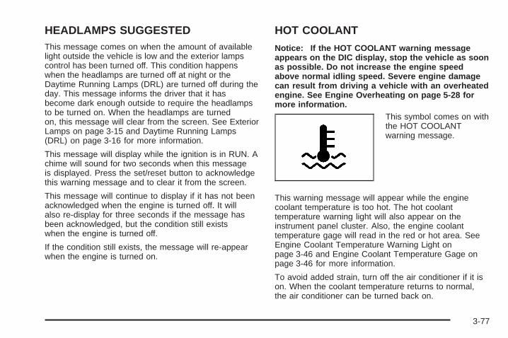
HEADLAMPS SUGGESTEDThis message comes on when the amount of availablelight outside the vehicle is low and the exterior lampscontrol has been turned off. This condition happenswhen the headlamps are turned off at night or theDaytime Running Lamps (DRL) are turned off during theday. This message informs the driver that it hasbecome dark enough outside to require the headlampsto be turned on. When the headlamps are turnedon, this message will clear from the screen. See ExteriorLamps on page 3-15 and Daytime Running Lamps(DRL) on page 3-16 for more information.
This message will display while the ignition is in RUN. Achime will sound for two seconds when this messageis displayed. Press the set/reset button to acknowledgethis warning message and to clear it from the screen.
This message will continue to display if it has not beenacknowledged when the engine is turned off. It willalso re-display for three seconds if the message hasbeen acknowledged, but the condition still existswhen the engine is turned off.
If the condition still exists, the message will re-appearwhen the engine is turned on.
HOT COOLANT
Notice: If the HOT COOLANT warning messageappears on the DIC display, stop the vehicle as soonas possible. Do not increase the engine speedabove normal idling speed. Severe engine damagecan result from driving a vehicle with an overheatedengine. See Engine Overheating on page 5-28 formore information.
This symbol comes on withthe HOT COOLANTwarning message.
This warning message will appear while the enginecoolant temperature is too hot. The hot coolanttemperature warning light will also appear on theinstrument panel cluster. Also, the engine coolanttemperature gage will read in the red or hot area. SeeEngine Coolant Temperature Warning Light onpage 3-46 and Engine Coolant Temperature Gage onpage 3-46 for more information.
To avoid added strain, turn off the air conditioner if it ison. When the coolant temperature returns to normal,the air conditioner can be turned back on.
3-77

This message will display only while the ignition is inRUN. A chime will sound continuously when thismessage is displayed. Press the set/reset button toacknowledge this message and to clear it fromthe screen.
This message will continue to display if it has not beenacknowledged when the engine is turned off. It willalso re-display for three seconds if the message hasbeen acknowledged, but the condition still existswhen the engine is turned off.
If the condition still exists, the message will re-appearwhen the engine is turned on.
HOT ENGINE OIL. REDUCE SPEEDOn some vehicles, this warning message comes onwhen the vehicle’s engine oil is above the proper engineoperating temperature. Reduce the speed of thevehicle. If the warning message continues to display,have the vehicle serviced by your GM dealer as soon aspossible. A chime will sound continuously when thismessage is displayed. Press the set/reset buttonto acknowledge this warning message. This clears itfrom the screen.
If the condition still exists, the message will re-appearwhen the engine is turned on.
HOT TRANS FLUID
This symbol comes on withthe HOT TRANS FLUIDwarning message.
This warning message will appear when the transaxlefluid in the vehicle is too hot. Stop the vehicle and allowit to idle until it cools down. If the warning messagecontinues to display, have the vehicle serviced by yourGM dealer as soon as possible.
If the vehicle has the Uplevel Trip Computer DIC, youcan determine the actual temperature of the transaxlefluid using the vehicle’s gages button. See DIC Controlsand Displays (Base Level DIC) on page 3-52 or DICControls and Displays (Uplevel DIC with Trip Computer)on page 3-60 for more information.
This message will display while the ignition is in RUN. Achime will sound for two seconds when this messageis displayed. Press the set/reset button to acknowledgethis message and to clear it from the screen.
3-78
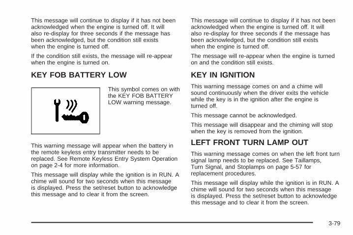
This message will continue to display if it has not beenacknowledged when the engine is turned off. It willalso re-display for three seconds if the message hasbeen acknowledged, but the condition still existswhen the engine is turned off.
If the condition still exists, the message will re-appearwhen the engine is turned on.
KEY FOB BATTERY LOW
This symbol comes on withthe KEY FOB BATTERYLOW warning message.
This warning message will appear when the battery inthe remote keyless entry transmitter needs to bereplaced. See Remote Keyless Entry System Operationon page 2-4 for more information.
This message will display while the ignition is in RUN. Achime will sound for two seconds when this messageis displayed. Press the set/reset button to acknowledgethis message and to clear it from the screen.
This message will continue to display if it has not beenacknowledged when the engine is turned off. It willalso re-display for three seconds if the message hasbeen acknowledged, but the condition still existswhen the engine is turned off.
The message will re-appear when the engine is turnedon and the condition still exists.
KEY IN IGNITIONThis warning message comes on and a chime willsound continuously when the driver exits the vehiclewhile the key is in the ignition after the engine isturned off.
This message cannot be acknowledged.
This message will disappear and the chiming will stopwhen the key is removed from the ignition.
LEFT FRONT TURN LAMP OUTThis warning message comes on when the left front turnsignal lamp needs to be replaced. See Taillamps,Turn Signal, and Stoplamps on page 5-57 forreplacement procedures.
This message will display while the ignition is in RUN. Achime will sound for two seconds when this messageis displayed. Press the set/reset button to acknowledgethis message and to clear it from the screen.
3-79

This message will continue to display if it has not beenacknowledged when the engine is turned off. It willalso re-display for three seconds if the message hasbeen acknowledged, but the condition still existswhen the engine is turned off.
If the condition still exists, the message will re-appearwhen the engine is turned on.
LEFT REAR TURN LAMP OUTThis warning message comes on when the left rear turnsignal lamp needs to be replaced. See Taillamps,Turn Signal, and Stoplamps on page 5-57 forreplacement procedures.
This message will display while the ignition is in RUN. Achime will sound for two seconds when this messageis displayed. Press the set/reset button to acknowledgethis message and to clear it from the screen.
This message will continue to display if it has not beenacknowledged when the engine is turned off. It willalso re-display for three seconds if the message hasbeen acknowledged, but the condition still existswhen the engine is turned off.
If the condition still exists, the message will re-appearwhen the engine is turned on.
LOW BRAKE FLUIDThis symbol comes on withthe LOW BRAKE FLUIDwarning message.
This warning message will appear when the brake fluidlevel is low. Have the brake system serviced by yourGM dealer as soon as possible. See Brakes onpage 5-42.The brake light will also appear on the instrument panelcluster when this message appears on the DIC. SeeBrake System Warning Light on page 3-42.This message will display only while the ignition isin RUN. A chime will sound for two seconds whilethis message is displayed. Press the set/reset buttonto acknowledge this message and to clear it fromthe screen.This message will continue to display if it has not beenacknowledged when the engine is turned off. It willalso re-display for three seconds if the message hasbeen acknowledged, but the condition still existswhen the engine is turned off.
If the condition exists, the message will re-appear whenthe engine is turned on.
3-80

LOW FUEL
This symbol comes onwith the LOW FUELwarning message.
This warning message will appear when the vehicle islow on fuel. Refill the fuel tank as soon as possible.
This message will display while the ignition is in RUN. Achime will sound for two seconds when this messageis displayed. Press the set/reset button to acknowledgethis message and to clear it from the screen.
This message will continue to display if it has not beenacknowledged when the engine is turned off. It willalso re-display for three seconds if the message hasbeen acknowledged, but the condition still existswhen the engine is turned off.
If the condition still exists, the message will re-appearwhen the engine is turned on.
LOW OIL LEVELThis symbol comes on withthe LOW OIL LEVELwarning message.
On some vehicles, this warning message appears whenthe vehicle’s engine oil is low. Fill the oil to the properlevel as soon as possible. See Engine CompartmentOverview on page 5-12 for engine oil fill location. Also,see Engine Oil on page 5-16 for information on thekind of oil to use and proper oil level. See SuperchargerOil on page 5-20 if the vehicle has a superchargedengine for information on the kind of oil to useand proper oil level.This message will display while the ignition is in RUN. Achime will sound for two seconds when this messageis displayed. Press the set/reset button to acknowledgethis message and to clear it from the screen.This message will continue to display if it has not beenacknowledged when the engine is turned off. It willalso re-display for three seconds if the message hasbeen acknowledged, but the condition still existswhen the engine is turned off.If the condition still exists, the message will re-appearwhen the engine is turned on.
3-81

LOW OIL PRESSURENotice: If the LOW OIL PRESSURE warningmessage appears on the DIC display, stop thevehicle immediately. Do not drive the vehicle untilthe cause of the low oil pressure is corrected.Severe engine damage can result from driving avehicle with low oil pressure. See Engine Oilon page 5-16 for more information.
This symbol comes on withthe LOW OIL PRESSUREwarning message.
This warning message will appear when the vehicle’sengine oil pressure is low. The low oil pressure warninglight will also appear on the instrument panel.Stop the vehicle immediately, as engine damage canresult from driving a vehicle with low oil pressure. Havethe vehicle serviced by your GM dealer as soon aspossible when this warning message is displayed.This message will display only while the ignition is inRUN. A chime will sound continuously when thismessage is displayed. Press the set/reset button toacknowledge this message and to clear it fromthe screen.
This message will continue to display if it has not beenacknowledged when the engine is turned off. It willalso re-display for three seconds if the message hasbeen acknowledged, but the condition still existswhen the engine is turned off.If the condition still exists, the message will re-appearwhen the engine is turned on.
LOW WASHER FLUID
This symbol comes on withthe LOW WASHER FLUIDwarning message.
This warning message appears when the windshieldwasher fluid is low. Fill the windshield washer reservoiras soon as possible. See Engine CompartmentOverview on page 5-12 for location of the windshieldwasher reservoir. Also, see Windshield Washer Fluid onpage 5-41 for more information.
This message will display only while the ignition is inRUN. A chime will sound for two seconds whenthis message is displayed. Press the set/reset buttonto acknowledge this message and to clear it fromthe screen.
3-82
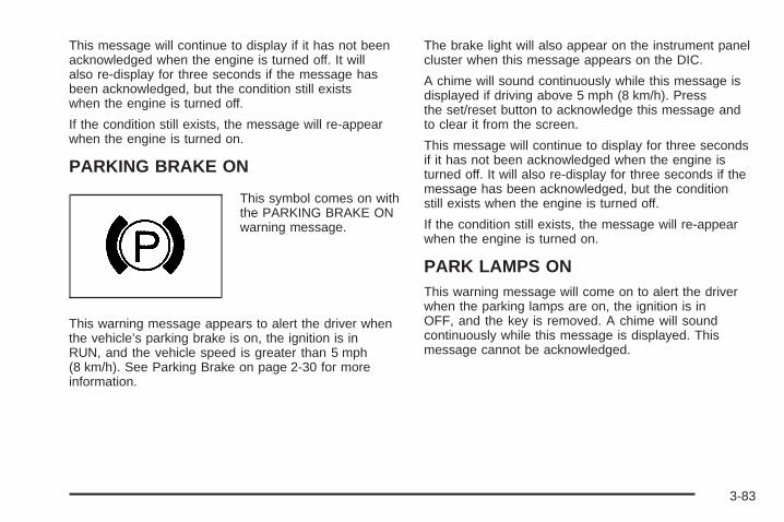
This message will continue to display if it has not beenacknowledged when the engine is turned off. It willalso re-display for three seconds if the message hasbeen acknowledged, but the condition still existswhen the engine is turned off.
If the condition still exists, the message will re-appearwhen the engine is turned on.
PARKING BRAKE ON
This symbol comes on withthe PARKING BRAKE ONwarning message.
This warning message appears to alert the driver whenthe vehicle’s parking brake is on, the ignition is inRUN, and the vehicle speed is greater than 5 mph(8 km/h). See Parking Brake on page 2-30 for moreinformation.
The brake light will also appear on the instrument panelcluster when this message appears on the DIC.
A chime will sound continuously while this message isdisplayed if driving above 5 mph (8 km/h). Pressthe set/reset button to acknowledge this message andto clear it from the screen.
This message will continue to display for three secondsif it has not been acknowledged when the engine isturned off. It will also re-display for three seconds if themessage has been acknowledged, but the conditionstill exists when the engine is turned off.
If the condition still exists, the message will re-appearwhen the engine is turned on.
PARK LAMPS ONThis warning message will come on to alert the driverwhen the parking lamps are on, the ignition is inOFF, and the key is removed. A chime will soundcontinuously while this message is displayed. Thismessage cannot be acknowledged.
3-83
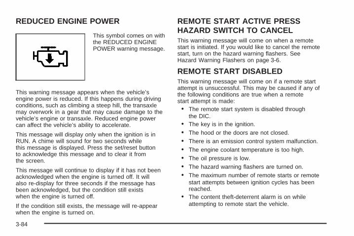
REDUCED ENGINE POWER
This symbol comes on withthe REDUCED ENGINEPOWER warning message.
This warning message appears when the vehicle’sengine power is reduced. If this happens during drivingconditions, such as climbing a steep hill, the transaxlemay overwork in a gear that may cause damage to thevehicle’s engine or transaxle. Reduced engine powercan affect the vehicle’s ability to accelerate.
This message will display only when the ignition is inRUN. A chime will sound for two seconds whilethis message is displayed. Press the set/reset buttonto acknowledge this message and to clear it fromthe screen.
This message will continue to display if it has not beenacknowledged when the engine is turned off. It willalso re-display for three seconds if the message hasbeen acknowledged, but the condition still existswhen the engine is turned off.
If the condition still exists, the message will re-appearwhen the engine is turned on.
REMOTE START ACTIVE PRESSHAZARD SWITCH TO CANCELThis warning message will come on when a remotestart is initiated. If you would like to cancel the remotestart, turn on the hazard warning flashers. SeeHazard Warning Flashers on page 3-6.
REMOTE START DISABLEDThis warning message will come on if a remote startattempt is unsuccessful. This may be caused if any ofthe following conditions are true when a remotestart attempt is made:• The remote start system is disabled through
the DIC.• The key is in the ignition.• The hood or the doors are not closed.• There is an emission control system malfunction.• The engine coolant temperature is too high.• The oil pressure is low.• The hazard warning flashers are turned on.• The maximum number of remote starts or remote
start attempts between ignition cycles has beenreached.
• The content theft-deterrent alarm is on whileattempting to remote start the vehicle.
3-84

See “REMOTE START” under DIC Controls andDisplays (Base Level DIC) on page 3-52 or DIC Controlsand Displays (Uplevel DIC with Trip Computer) onpage 3-60 and “Remote Vehicle Start” under RemoteKeyless Entry System Operation on page 2-4 formore information.
RIGHT FRONT TURN LAMP OUTThis warning message will come on when the vehicle’sright front turn signal needs to be replaced. SeeFront Turn Signal, Parking and Fog Lamps on page 5-56for bulb replacement procedures.
This message will display only while the ignition is inRUN. A chime will sound for two seconds whilethis message is displayed. Press the set/reset buttonto acknowledge this message and to clear it fromthe screen.
This message will continue to display if it has not beenacknowledged when the engine is turned off. It willalso re-display for three seconds if the message hasbeen acknowledged, but the condition still existswhen the engine is turned off.
If the condition still exists, the message will re-appearwhen the engine is turned on.
RIGHT REAR TURN LAMP OUTThis warning message will come on when the vehicle’sright rear turn signal needs to be replaced. SeeTaillamps, Turn Signal, and Stoplamps on page 5-57 forbulb replacement procedures.
This message will display only while the ignition is inRUN. A chime will sound for two seconds whilethis message is displayed. Press the set/reset buttonto acknowledge this message and to clear it fromthe screen.
This message will continue to display if it has not beenacknowledged when the engine is turned off. It willalso re-display for three seconds if the message hasbeen acknowledged, but the condition still existswhen the engine is turned off.
If the condition still exists, the message will re-appearwhen the engine is turned on.
3-85
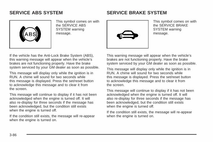
SERVICE ABS SYSTEM
This symbol comes on withthe SERVICE ABSSYSTEM warningmessage.
If the vehicle has the Anti-Lock Brake System (ABS),this warning message will appear when the vehicle’sbrakes are not functioning properly. Have the brakesystem serviced by your GM dealer as soon as possible.
This message will display only while the ignition is inRUN. A chime will sound for two seconds whilethis message is displayed. Press the set/reset buttonto acknowledge this message and to clear it fromthe screen.
This message will continue to display if it has not beenacknowledged when the engine is turned off. It willalso re-display for three seconds if the message hasbeen acknowledged, but the condition still existswhen the engine is turned off.
If the condition still exists, the message will re-appearwhen the engine is turned on.
SERVICE BRAKE SYSTEM
This symbol comes on withthe SERVICE BRAKESYSTEM warningmessage.
This warning message will appear when the vehicle’sbrakes are not functioning properly. Have the brakesystem serviced by your GM dealer as soon as possible.
This message will display only while the ignition is inRUN. A chime will sound for two seconds whilethis message is displayed. Press the set/reset buttonto acknowledge this message and to clear it fromthe screen.
This message will continue to display if it has not beenacknowledged when the engine is turned off. It willalso re-display for three seconds if the message hasbeen acknowledged, but the condition still existswhen the engine is turned off.
If the condition still exists, the message will re-appearwhen the engine is turned on.
3-86

SERVICE BRAKE APPLY SENSORThis message will come on when the brake apply sensoris not functioning properly. The vehicle still has brakeswhen this warning message displays, but you shouldhave the vehicle serviced by your GM dealer as soonas possible.
This message will display only while the ignition is inRUN. A chime will sound for two seconds whilethis message is displayed. Press the set/reset buttonto acknowledge this message and to clear it fromthe screen.
This message will continue to display if it has not beenacknowledged when the engine is turned off. It willalso re-display for three seconds if the message hasbeen acknowledged, but the condition still existswhen the engine is turned off.
If the condition still exists, the message will re-appearwhen the engine is turned on.
SERVICE PARK LAMPSThis warning message will come on if one of thevehicle’s parking lamps needs to be replaced. See FrontTurn Signal, Parking and Fog Lamps on page 5-56 forbulb replacement procedures.
This message will display only while the ignition is inRUN. A chime will sound for two seconds whilethis message is displayed. Press the set/reset buttonto acknowledge this message and to clear it fromthe screen.
This message will continue to display if it has not beenacknowledged when the engine is turned off. It willalso re-display for three seconds if the message hasbeen acknowledged, but the condition still existswhen the engine is turned off.
If the condition still exists, the message will re-appearwhen the engine is turned on.
3-87

SERVICE STABILITY SYSTEM
This symbol comes on withthe SERVICE STABILITYSYSTEM warningmessage.
If the vehicle has the StabiliTrak® Plus system, thiswarning message will appear when it is not functioningproperly. A warning light will also appear on theinstrument panel cluster. See Traction Control System(TCS) Warning Light on page 3-45 or Enhanced TractionSystem Warning Light on page 3-45. See StabiliTrak®
Plus System on page 4-12 for more information.Have the StabiliTrak® Plus system serviced by yourGM dealer as soon as possible.
This message will display only while the ignition is inRUN. A chime will sound for two seconds whilethis message is displayed. Press the set/reset buttonto acknowledge this message and to clear it fromthe screen.
This message will continue to display if it has not beenacknowledged when the engine is turned off. It willalso re-display for three seconds if the message hasbeen acknowledged, but the condition still existswhen the engine is turned off.If the condition still exists, the message will re-appearwhen the engine is turned on.
3-88

SERVICE THEFT SYSTEMThis warning message comes on if there is a problemwith the theft-deterrent system programmed in thekey. A fault has been detected in the system whichmeans that the system is disabled and it is not protectingthe vehicle. The vehicle usually restarts; however, youmay want to take the vehicle to your GM dealerbefore turning off the engine. See Keys on page 2-2 forinformation on the PASS-Key® III system.This message will display only while the ignition is inRUN. A chime will sound for two seconds while thismessage is displayed. Press the set/reset button toacknowledge this message and to clear it from thescreen.This message will continue to display if it has not beenacknowledged when the engine is turned off. It willalso re-display for three seconds if the message hasbeen acknowledged, but the condition still existswhen the engine is turned off.If the condition still exists, the message will re-appearwhen the engine is turned on.
SERVICE TRACTION SYSTEM
This symbol will come onwith the SERVICETRACTION SYSTEMwarning message.
If the vehicle has the traction control system, thiswarning message appears when the system is notfunctioning properly. A warning light will also appear onthe instrument panel cluster. See Traction ControlSystem (TCS) Warning Light on page 3-45 or EnhancedTraction System Warning Light on page 3-45. SeeTraction Control System (TCS) on page 4-9 for moreinformation. Have the traction control system serviced byyour GM dealer as soon as possible.
This message will display only while the ignition is inRUN. A chime will sound for two seconds whilethis message is displayed. Press the set/reset buttonto acknowledge this message and to clear it fromthe screen.
3-89

This message will continue to display if it has not beenacknowledged when the engine is turned off. It willalso re-display for three seconds if the message hasbeen acknowledged, but the condition still existswhen the engine is turned off.
If the condition still exists, the message will re-appearwhen the engine is turned on.
SERVICE VARIABLE EFFORTSTEERING
This symbol comes on withthe SERVICE VARIABLEEFFORT STEERINGwarning message.
If the vehicle has the variable effort steering system,this warning message will display if this system isnot functioning properly. See Steering on page 4-13 formore information. Have your system serviced byyour GM dealer as soon as possible.
This message will display only while the ignition is inRUN. A chime will sound for two seconds whilethis message is displayed. Press the set/reset buttonto acknowledge this message and to clear it fromthe screen.
This message will continue to display if it has not beenacknowledged when the engine is turned off. It willalso re-display for three seconds if the message hasbeen acknowledged, but the condition still existswhen the engine is turned off.
If the condition still exists, the message will re-appearwhen the engine is turned on.
3-90

SERVICE VEHICLE SOON
This symbol comes on withthe SERVICE VEHICLESOON warning message.
This warning message displays when a non-emissionsrelated malfunction occurs. Have the vehicle servicedby your GM dealer as soon as possible.
This message will display only while the ignition is inRUN. A chime will sound for two seconds whilethis message is displayed. Press the set/reset buttonto acknowledge this message and to clear it fromthe screen.
This message will continue to display if it has not beenacknowledged when the engine is turned off. It willalso re-display for three seconds if the message hasbeen acknowledged, but the condition still existswhen the engine is turned off.
If the condition still exists, the message will re-appearwhen the engine is turned on.
STABILITY CONTROL ACTIVE
This symbol comes on withthe STABILITY CONTROLACTIVE warningmessage.
If the vehicle has the StabiliTrak® Plus system, thiswarning message appears when the system is engagedand actively assisting the driver with directionalcontrol of the vehicle. Slippery road conditions may existwhen this warning message is displayed, so drivingshould be adjusted accordingly. STABILITY CONTROLACTIVE will also appear in the Head-Up Display(HUD), if your vehicle has this feature.
This message will display only while the ignition is inRUN. This message stays on until road conditionschange and StabiliTrak® Plus is not active.
This message cannot be acknowledged and clearedfrom the screen.
3-91

STABILITY CONTROL OFF
This symbol comes on withthe STABILITY CONTROLOFF warning message.
If the vehicle has the StabiliTrak® Plus system, thiswarning message will appear when the system turns off.This message will display only while the ignition is inRUN. A chime will sound once and the messagewill stay on for three seconds and then disappear. Awarning light indicating that this system is deactivatedwill also appear on the instrument panel cluster.See Traction Control System (TCS) Warning Light onpage 3-45 or Enhanced Traction System Warning Lighton page 3-45.
When the StabiliTrak® Plus system is off, the systemwill not be engaged and will not actively assist the driverwith directional control of the vehicle. See StabiliTrak®
Plus System on page 4-12.
Any of the following conditions may cause theStabiliTrak® Plus system to turn off:
• The StabiliTrak® Plus system on the GXP option ismanually turned off. See StabiliTrak® Plus Systemon page 4-12 for more information.
• The battery is low.
• There is a StabiliTrak® Plus system failure. Seeyour GM dealer for service.
STARTING DISABLED DUE TOELECTRONIC THROTTLE CONTROLThis warning message comes on when there is amalfunction with the electronic throttle control whichprevents the vehicle from starting. Have the vehicleserviced by your GM dealer.
This message will only appear while the ignition is inRUN, and will not disappear until the problem isresolved. A chime will sound for two seconds. Thismessage cannot be acknowledged.
3-92

STARTING DISABLED DUE TO THEFTSYSTEMThis warning message comes on when the systemdetects a malfunction in the content theft-deterrentsystem and prevents the vehicle from starting.
This message will only appear while the ignition is inRUN, and will not disappear until the problem isresolved. A chime will sound for two seconds. Thismessage cannot be acknowledged.
TRACTION CONTROL ACTIVE
This symbol comes on withthe TRACTION CONTROLACTIVE message.
If the vehicle has the traction control system, thismessage will appear when the system is on. TRACTIONCONTROL ACTIVE will also appear in the Head-UpDisplay (HUD), if your vehicle has this feature.
This message only displays while the ignition is in RUNand will not disappear until driving conditions changeand the traction control is no longer active.
This message cannot be acknowledged or cleared fromthe screen.
TRACTION CONTROL OFF
This symbol comes on withthe TRACTION CONTROLOFF message.
If the vehicle has the traction control system, thismessage will appear when the traction control systemturns off. TRACTION CONTROL OFF will also appear inthe Head-Up Display (HUD), if your vehicle has thisfeature. This message will only display while the ignitionis in RUN and will disappear after three seconds. Achime will sound once and the message will stay on forthree seconds and then disappear. A warning lightindicating that this system is deactivated will also appearon the instrument panel cluster. See Traction ControlSystem (TCS) Warning Light on page 3-45 or EnhancedTraction System Warning Light on page 3-45.
3-93

Any of the following conditions may cause the tractioncontrol system to turn off:
• The traction control system is turned off by pressingthe TC (traction control) button located on thecenter console. See Traction Control System (TCS)on page 4-9 or Enhanced Traction System (ETS)on page 4-11 for more information.
• The battery is low.
• There is a traction control system failure. See yourGM dealer for service.
TURN SIGNAL ONThis message comes on if the vehicle is driven for morethan 0.75 mile (1.21 km) while one of the turn signalsare on. It appears as a reminder to turn off the turnsignal.
This message only displays when the ignition is in RUN.A chime will sound for two seconds and the messagewill not disappear until the turn signal is manually turnedoff, or a turn is completed.
Audio System(s)Determine which radio your vehicle has and then readthe pages following to familiarize yourself with itsfeatures.Driving without distraction is a necessity for a saferdriving experience. See Defensive Driving on page 4-2.By taking a few moments to read this manual andget familiar with your vehicle’s audio system, you canuse it with less effort, as well as take advantage ofits features. While your vehicle is parked, set up youraudio system by presetting your favorite radio stations,setting the tone and adjusting the speakers. Then,when driving conditions permit, you can tune to yourfavorite stations using the presets and steeringwheel controls (if equipped).
{CAUTION:
This system provides you with a far greateraccess to audio stations and song listings.Giving extended attention to entertainmenttasks while driving can cause a crash and youor others can be injured or killed. Always keepyour eyes on the road and your mind on thedrive — avoid engaging in extended searchingwhile driving.
3-94

Keeping your mind on the drive is important for safedriving. For more information, see Defensive Driving onpage 4-2. Get familiar with your vehicle’s audiosystem so you can use it with less effort and take fulladvantage of its features.
Here are some ways in which you can help avoiddistraction while driving.
While your vehicle is parked:
• Familiarize yourself with all of its controls.
• Familiarize yourself with its operation.
• Set up your audio system by presetting yourfavorite radio stations, setting the tone, andadjusting the speakers. Then, when drivingconditions permit, you can tune to your favoriteradio stations using the presets and steering wheelcontrols (if equipped).
Notice: Before adding any sound equipment toyour vehicle, such as an audio system, CD player,CB radio, mobile telephone, or two-way radio, makesure that it can be added by checking with yourdealer. Also, check federal rules covering mobileradio and telephone units. If sound equipment canbe added, it is very important to do it properly.
Added sound equipment may interfere with theoperation of your vehicle’s engine, radio, or othersystems, and even damage them. Your vehicle’ssystems may interfere with the operation of soundequipment that has been added.
Notice: The chime signals related to seat belts,parking brake, and other functions of your vehicleoperate through the GM radio/entertainment system.If that equipment is replaced or additionalequipment is added to your vehicle, the chimes maynot work. Make sure that replacement or additionalequipment is compatible with your vehicle beforeinstalling it. See Accessories and Modifications onpage 5-3.
Your vehicle has a feature called Retained AccessoryPower (RAP). With RAP, the audio system can beplayed even after the ignition is turned off. See RetainedAccessory Power (RAP) on page 2-22 for moreinformation.
3-95

Setting the TimeThe radio may have a button marked with an H or HRto represent hours and an M or MIN to representminutes.
Press and hold the hour button until the correct hourappears on the display. AM will appear for morninghours. Press and hold the minute button until the correctminute appears on the display. The time can be setwith the ignition on or off.
To synchronize the time with an FM station broadcastingRadio Data System (RDS) information, press andhold the hour and minute buttons at the same time untilUPDATED appears on the display. If the time is notavailable from the station, NO UPDATE will appear onthe display.
RDS time is broadcast once a minute. After tuning to anRDS broadcast station, it may take a few minutes forthe time to update.
Radio with CD (Base Level)
Radio Data System (RDS)The audio system has a Radio Data System (RDS).RDS features are available for use only on FM stationsthat broadcast RDS information.
With RDS, the radio can do the following:
• Seek to stations broadcasting the selected type ofprogramming
• Receive announcements concerning local andnational emergencies
• Display messages from radio stations
• Seek to stations with traffic announcements
3-96
This system relies upon receiving specific informationfrom these stations and will only work when theinformation is available. In rare cases, a radio stationmay broadcast incorrect information that will causethe radio features to work improperly. If this happens,contact the radio station.
While the radio is tuned to an RDS station, the stationname or call letters will appear on the display instead ofthe frequency. RDS stations may also provide the time ofday, a program type (PTY) for current programming, andthe name of the program being broadcast.
XM™ Satellite Radio ServiceXM™ is a satellite radio service that is based inthe 48 contiguous United States and in Canada(if available). XM™ offers over 100 coast-to-coastchannels including music, news, sports, talk, andchildren’s programming. XM™ provides digital qualityaudio and text information that includes song title andartist name. A service fee is required in order to receivethe XM™ service. For more information, contact XM™ atwww.xmradio.com or call 1-800-852-XMXM (9696).
Playing the Radio
PWR (Power): Push this knob to turn the system onand off.
VOL (Volume): Turn this knob to increase or todecrease the volume.
SCV (Speed-Compensated Volume): With SCV, theaudio system adjusts automatically to make up forroad and wind noise as you drive.
Set the volume at the desired level. Press this button toselect MIN, MED, or MAX. Each higher setting willallow for more volume compensation at faster vehiclespeeds. Then, as you drive, SCV automaticallyincreases the volume, as necessary, to overcome noiseat any speed. The volume level should always soundthe same to you as you drive. To turn SCV off, press thisbutton until OFF appears on the display.
RCL (Recall): Push this knob to switch the displaybetween the radio station frequency and the time. Whenthe ignition is off, push this knob to display the time.
For RDS, push the RCL knob to change what appearson the display while using RDS. The display optionsare station name, RDS station frequency, PTY, and thename of the program (if available).
For XM™ (if equipped), push the RCL knob while inXM™ mode to retrieve four different categories ofinformation related to the current song or channel:Artist, Song Title, Category or PTY, ChannelNumber/Channel Name.
To change the default on the display, push the RCLknob until you see the display you want, then hold theknob until the display flashes. The selected displaywill now be the default.
3-97
Finding a Station
BAND: Press this button to switch between FM1, FM2,AM, or XM1 or XM2 (if equipped). The display willshow the selection.
TUNE: Turn this knob to select radio stations.
w SEEK x: Press the up or the down arrow to go tothe next or to the previous station and stay there.
The radio will only seek stations with a strong signalthat are in the selected band.
w SCAN x: Press and hold either arrow fortwo seconds until SCAN appears on the display andyou hear a beep. The radio will go to a station, play fora few seconds, then go on to the next station. Presseither arrow again to stop scanning.
To scan preset stations, press and hold either SCANarrow for more than four seconds until PSCAN and thepreset number appear on the display and you heartwo beeps. The radio will go to the first preset stationstored on the pushbuttons, play for a few seconds, thengo on to the next preset station. Press either SCANarrow again to stop scanning presets.
The radio will only scan stations with a strong signalthat are in the selected band.
Setting Preset StationsUp to 30 stations (six FM1, six FM2, and six AM,six XM1 and six XM2 (if equipped)), can be programmedon the six numbered pushbuttons, by performing thefollowing steps:
1. Turn the radio on.
2. Press BAND to select FM1, FM2, AM, or XM1or XM2.
3. Tune in the desired station.
4. Press EQ to select the equalization.
5. Press and hold one of the six numberedpushbuttons until you hear a beep. Whenever thatnumbered pushbutton is pressed, the stationthat was set will return and the equalization thatwas selected will be stored for that pushbutton.
6. Repeat the steps for each pushbutton.
3-98

Setting the Tone(Bass/Midrange/Treble)
TONE: Press and release this button until BASS, MID,or TREB appears on the display. The SELECT LEDindicator will light to show that the tone control can beadjusted. Turn the SELECT knob to increase or todecrease. If a station is weak or noisy, decreasethe treble.
To return all of the tone controls to the middle position,press and hold the TONE button until FLAT appearson the display
EQ (Equalizer): Press this button to select customizedequalization settings.
Up to six customized equalization settings, can beprogrammed, by performing the following steps:
1. Turn the radio on.
2. Use the TONE button and the SELECT knob tocreate the equalization.
3. Press and hold the EQ button for two seconds.SELECT EQ # will appear on the display and theEQ symbol will flash.
4. Press EQ or turn the SELECT knob to select theEQ number.
5. Press and hold the EQ button or push the SELECTknob to store the equalization setting and thenumber. EQ SAVED will appear on the display andyou will hear a beep.
6. Repeat the steps for the other EQ settingsand numbers.
EQ 5 has been programmed at the factory for use withtalk radio, but it can be preset to a different tone.
Adjusting the Speakers (Balance/Fade)
BAL (Balance): To adjust the balance between theright and the left speakers, press and release this buttonuntil BAL appears on the display. The SELECT LEDindicator will light to show that the speakers canbe adjusted. Turn the SELECT knob to move the soundtoward the right or the left speakers.
FADE: To adjust the fade between the front and therear speakers, press and release this button until FADEappears on the display. The SELECT LED indicatorwill light to show that the speakers can be adjusted. Turnthe SELECT knob to move the sound toward the frontor the rear speakers.
Pressing and holding the BAL FADE button fortwo seconds will return all speaker settings to themiddle position.
3-99

Finding a Program Type (PTY) Station(RDS and XM™)To select and find a desired PTY perform the following:
1. Press the PROG TYPE button to activate programtype select mode. PTY will appear on the display.
2. Turn the SELECT knob to select a PTY.
3. Once the desired PTY is displayed, press eitherSEEK arrow to select the PTY and take you tothe PTY’s first station.
4. To go to another station within that PTY, while thePTY is displayed, press either SEEK arrow once. Ifthe PTY is not displayed, press either SEEKarrow twice to display the PTY and then to go toanother station.
5. Press PROG TYPE to exit program typeselect mode.If PTY times out and is no longer on the display, goback to Step 1.
If both PTY and TRAF are on, the radio will search forstations with the selected PTY and trafficannouncements.
SCAN: Scan the stations within a PTY by performingthe following:
1. Press PROG TYPE to activate program type selectmode. PTY will appear on the display.
2. Turn the SELECT knob to select a PTY.
3. Once the desired PTY is displayed, press and holdeither SCAN arrow, and the radio will beginscanning the stations in the PTY.
4. Press either SCAN arrow to stop at a station.
If both PTY and TRAF are on, the radio will scan forstations with the selected PTY and trafficannouncements.
BAND (Alternate Frequency): Alternate frequencyallows the radio to switch to a stronger station with thesame program type. To turn alternate frequency on,press and hold BAND for two seconds. AF ON willappear on the display. The radio may switch to stationswith a stronger frequency.
To turn alternate frequency off, press and hold BANDagain for two seconds. AF OFF will appear on thedisplay. The radio will not switch to other stations.
This function does not apply for XM™ SatelliteRadio Service.
3-100
Setting Preset PTYs (RDS Only)These pushbuttons have factory PTY presets. Up to12 PTYs (six FM1 and six FM2), can be programmed onthe six numbered pushbuttons, by performing thefollowing steps:
1. Press BAND to select FM1 or FM2.
2. Press PROG TYPE to activate program type selectmode. PTY will appear on the display.
3. Turn the SELECT knob to select a PTY.
4. Press and hold one of the six numberedpushbuttons until you hear a beep. Whenever thatnumbered pushbutton is pressed, the PTY thatwas set will return, if program type select mode isactivated.
5. Repeat the steps for each pushbutton.
RDS MessagesALERT!: Alert warns of local or national emergencies.When an alert announcement comes on the currentradio station, ALERT! will appear on the display. You willhear the announcement, even if the volume is low ora CD is playing. If a CD is playing, play will stop duringthe announcement. Alert announcements cannot beturned off.
ALERT! will not be affected by tests of the emergencybroadcast system. This feature is not supported byall RDS stations.
INFO (Information): If the current station has amessage, INFO will appear on the display. Press thisbutton to see the message. The message may displaythe artist, song title, call in phone numbers, etc.
If the entire message is not displayed, parts of themessage will appear every three seconds. To scrollthrough the message, press and release the INFObutton. A new group of words will appear on the displayafter every press of the button. Once the completemessage has been displayed, INFO will disappear fromthe display until another new message is received.The last message can be displayed by pressingthe INFO button. You can view the last messageuntil a new message is received or a different stationis tuned to.
3-101

TRAF (Traffic): If TRAF appears on the display, thetuned station broadcasts traffic announcements.To receive the traffic announcement from the tunedstation, press this button. Brackets will be displayedaround TRAF and when a traffic announcement comeson the tuned radio station you will hear it.
If the station does not broadcast traffic announcements,press the TRAF button and the radio will seek to astation that does. When a station that broadcasts trafficannouncements is found, the radio will stop seekingand brackets will be displayed around TRAF. If nostation is found that broadcasts traffic announcements,NO TRAFFIC will appear on the display.
If the brackets are on the display and TRAF is not,press the TRAF button to remove the brackets or usethe TUNE knob or the SEEK arrows to go to astation that supports traffic announcements.
The radio will play the traffic announcement if thevolume is low. The radio will interrupt the play of a CD ifthe last tuned station broadcasts traffic announcementsand the brackets are displayed.
This function does not apply to XM™ Satellite RadioService.
Radio Messages
CALIBRATE: The audio system has been calibrated foryour vehicle from the factory. If CALIBRATE appearson the display it means that the radio has not beenconfigured properly for your vehicle and must bereturned your GM dealer for service.
LOCKED: This message is displayed when theTHEFTLOCK® system has locked up. Take the vehicleto your GM dealer for service.
If any error occurs repeatedly or if an error cannot becorrected, contact your dealer.
3-102
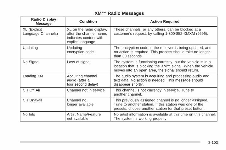
XM™ Radio MessagesRadio Display
Message Condition Action Required
XL (ExplicitLanguage Channels)
XL on the radio display,after the channel name,indicates content withexplicit language.
These channels, or any others, can be blocked at acustomer’s request, by calling 1-800-852-XMXM (9696).
Updating Updatingencryption code
The encryption code in the receiver is being updated, andno action is required. This process should take no longerthan 30 seconds.
No Signal Loss of signal The system is functioning correctly, but the vehicle is in alocation that is blocking the XM™ signal. When the vehiclemoves into an open area, the signal should return.
Loading XM Acquiring channelaudio (after afour second delay)
The audio system is acquiring and processing audio andtext data. No action is needed. This message shoulddisappear shortly.
CH Off Air Channel not in service This channel is not currently in service. Tune toanother channel.
CH Unavail Channel nolonger available
This previously assigned channel is no longer assigned.Tune to another station. If this station was one of thepresets, choose another station for that preset button.
No Info Artist Name/Featurenot available
No artist information is available at this time on this channel.The system is working properly.
3-103

XM™ Radio Messages (cont’d)Radio Display
Message Condition Action Required
No Info Song/Program Titlenot available
No song title information is available at this time on thischannel. The system is working properly.
No Info Category Namenot available
No category information is available at this time on thischannel. The system is working properly.
No Info No Text/Informationalmessage available
No text or informational messages are available at this timeon this channel. The system is working properly.
Not Found No channel available forthe chosen category
There are no channels available for the selected category.The system is working properly.
XM Locked Theft lock active The XM™ receiver in the vehicle may have previously beenin another vehicle. For security purposes, XM™ receiverscannot be swapped between vehicles. If this message isreceived after having your vehicle serviced, check with theservicing facility.
Radio ID Radio ID label(channel 0)
If tuned to channel 0, this message will alternate with theXM™ Radio eight digit radio ID label. This label is neededto activate the service.
Unknown Radio ID not known(should only be ifhardware failure)
If this message is received when tuned to channel 0, theremay be a receiver fault. Consult with your GM dealer.
Chk XMRcvr Hardware failure If this message does not clear within a short period of time,the receiver may have a fault. Consult with your GM dealer.
3-104

Playing a CDInsert a CD partway into the slot, label side up. Theplayer will pull it in and the CD should begin playing. Ifyou want to insert a CD when the ignition is off, firstpress the eject button or push the RCL knob. Ifyou insert a CD with the radio off and the ignition on, itwill start to play.
The CD symbol will appear on the display when a CD isloaded. The track number will appear on the display,as each new track starts to play.
If the ignition or the radio is turned off with a CD in theplayer, it will stay in the player. When the ignition orthe radio is turned on, the CD will start playing where itstopped, if it was the last selected audio source.
The CD player can play the smaller 3 inch (8 cm) singleCDs with an adapter ring. Full-size CDs and thesmaller CDs are loaded in the same manner.
If playing a CD-R, the sound quality may be reduced dueto CD-R quality, the method of recording, the quality ofthe music that has been recorded, and the way the CD-Rhas been handled. There may be an increase in skipping,difficulty in finding tracks, and/or difficulty in loading andejecting. If these problems occur, check the bottomsurface of the CD. If the surface of the CD is damaged,such as cracked, broken, or scratched, the CD will notplay properly. If the surface of the CD is soiled, see Careof Your CDs on page 3-141 for more information.
If there is no apparent damage, try a known good CD.
Do not add any label to a CD, it could get caught in theCD player. If a CD is recorded on a personal computerand a description label is needed, try labeling the top ofthe recorded CD with a marking pen instead.
Notice: If you add any label to a CD, insert morethan one CD into the slot at a time, or attemptto play scratched or damaged CDs, you coulddamage the CD player. When using the CD player,use only CDs in good condition without anylabel, load one CD at a time, and keep the CD playerand the loading slot free of foreign materials,liquids, and debris.
If an error appears on the display, see “CD Messages”later in this section.
\ 1 (Forward): Press and hold this pushbutton toadvance quickly within a track. You will hear sound at areduced volume. Release this pushbutton to play thepassage. The elapsed time of the track will appearon the display.
RDM 3 (Random): Press this pushbutton to hear thetracks in random, rather than sequential, order.RDM and the track number will appear on the display.Press RDM again to turn off random play.
3-105

4s (Reverse): Press and hold this pushbutton toreverse quickly within a track. You will hear sound at areduced volume. Release this pushbutton to play thepassage. The elapsed time of the track will appearon the display.
EQ (Equalizer): Press EQ to select the desiredcustomized equalization setting while playing a CD. Theequalization will be automatically set whenever youplay a CD. See “EQ” listed previously for moreinformation.
w SEEK x: Press the down arrow to go to the startof the current track if more than eight seconds haveplayed. Press the up arrow to go to the next track.If either arrow is held or pressed more than once, theplayer will continue moving backward or forward throughthe CD.
w SCAN x: Press and hold either arrow for morethan two seconds until SCAN and the track numberappear on the display and you hear a beep. The CD willgo to the next track, play for a few seconds, then goon to the next track. Press either arrow again tostop scanning.
RCL (Recall): Push this knob to see how long thecurrent track has been playing. To change the defaulton the display, track and elapsed time, push theknob until you see the display you want, then hold theknob until the display flashes. The selected displaywill now be the default. While elapsed time is showing,CD TIME will appear on the display.
BAND: Press this button to listen to the radio when aCD is playing. The inactive CD will remain safelyinside the radio for future listening.
CD AUX (Auxiliary): Press this button to play a CDwhen listening to the radio. The CD symbol will appearon the display when a CD is loaded.
Z (Eject): Press this button to eject a CD. Eject maybe activated with either the ignition or radio off. CDsmay be loaded with the ignition and radio off, ifthis button is pressed first.
3-106
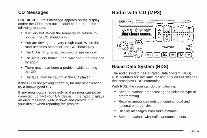
CD Messages
CHECK CD: If this message appears on the displayand/or the CD comes out, it could be for one of thefollowing reasons:
• It is very hot. When the temperature returns tonormal, the CD should play.
• You are driving on a very rough road. When theroad becomes smoother, the CD should play.
• The CD is dirty, scratched, wet, or upside down.
• The air is very humid. If so, wait about an hour andtry again.
• There may have been a problem while burningthe CD.
• The label may be caught in the CD player.
If the CD is not playing correctly, for any other reason,try a known good CD.
If any error occurs repeatedly or if an error cannot becorrected, contact your GM dealer. If the radio displaysan error message, write it down and provide it toyour dealer when reporting the problem.
Radio with CD (MP3)
Radio Data System (RDS)The audio system has a Radio Data System (RDS).RDS features are available for use only on FM stationsthat broadcast RDS information.
With RDS, the radio can do the following:
• Seek to stations broadcasting the selected type ofprogramming
• Receive announcements concerning local andnational emergencies
• Display messages from radio stations
• Seek to stations with traffic announcements
3-107

This system relies upon receiving specific informationfrom these stations and will only work when theinformation is available. In rare cases, a radio stationmay broadcast incorrect information that will causethe radio features to work improperly. If this happens,contact the radio station.While the radio is tuned to an RDS station, the stationname or the call letters will appear on the display insteadof the frequency. RDS stations may also provide thetime of day, a program type (PTY) for currentprogramming, and the name of the program beingbroadcast.
XM™ Satellite Radio ServiceXM™ is a satellite radio service that is based in the48 contiguous United States and in Canada (if available).XM™ offers over 100 coast-to-coast channels includingmusic, news, sports, talk, and children’s programming.XM™ provides digital quality audio and text informationthat includes song title and artist name. A service fee isrequired in order to receive the XM™ service. For moreinformation, contact XM™ at www.xmradio.com or call1-800-852-XMXM (9696).
Playing the RadioPWR (Power): Push this knob to turn the system onand off.VOL (Volume): Turn this knob to increase or todecrease the volume.
RCL (Recall): Push this knob to switch the displaybetween the radio station frequency and the time.When the ignition is turned off, push this knob todisplay the time.
For XM™ (if equipped), push the RCL knob while inXM™ mode to retrieve four different categories ofinformation related to the current song or channel:Artist, Song Title, Category or PTY, ChannelNumber/Channel Name.
To change the default on the display, push the RCLknob until you see the display you want, then hold theknob until the display flashes. The selected displaywill now be the default.
SCV (Speed-Compensated Volume): With SCV, theaudio system adjusts automatically to make up forroad and wind noise as you drive.
Set the volume at the desired level. Press this button toselect MIN, MED, or MAX. Each higher setting allowsfor more volume compensation at faster vehicle speeds.Then, as you drive, SCV automatically increases thevolume, as necessary, to overcome noise at any speed.The volume level should always sound the same toyou as you drive. To turn SCV off, press this button untilOFF appears on the display.
3-108
Finding a Station
BAND: Press this button to switch between FM1, FM2,AM, or XM1 or XM2 (if equipped). The display willshow the selection.
TUNE: Turn this knob to select radio stations.
w SEEK x: Press the up or the down arrow to go tothe next or to the previous station and stay there.
The radio will only seek stations with a strong signalthat are in the selected band.
w SCAN x: Press and hold either SCAN arrow fortwo seconds until SCAN appears on the display and youhear a beep. The radio will go to a station, play for afew seconds, then go on to the next station. Press eitherSCAN arrow again to stop scanning.
To scan preset stations, press and hold either SCANarrow for more than four seconds until PSCAN and thepreset number appear on the display and you willhear a double beep. The radio will go to the first presetstation, play for a few seconds, then go on to thenext preset station. Press either SCAN arrow again tostop scanning presets.
The radio will only scan stations with a strong signalthat are in the selected band.
Setting Preset StationsUp to 30 stations (six FM1, six FM2, and six AM,six XM1 and six XM2 (if equipped)), can be programmedon the six numbered pushbuttons, by performing thefollowing steps:
1. Turn the radio on.
2. Press BAND to select FM1, FM2, AM, or XM1or XM2.
3. Tune in the desired station.
4. Press EQ to select the equalization.
5. Press and hold one of the six numberedpushbuttons until you hear a beep. Whenever thatnumbered pushbutton is pressed, the stationthat was set will return and the equalization thatwas selected will be stored for that pushbutton.
6. Repeat the steps for each pushbutton.
Setting the Tone(Bass/Midrange/Treble)
TONE: Press and release this button until BASS,MID, or TREB appears on the display. The SELECTLED indicator will light to show that the tone control canbe adjusted. Turn the SELECT knob to increase or todecrease. If a station is weak or noisy, decreasethe treble.
3-109
Pressing and holding the TONE button until FLATappears on the display will return all of the tone controlsto the middle position.
EQ (Equalizer): Press this button to select customizedbass, midrange, and treble equalization settings.
Up to six customized equalization settings, can beprogrammed on the six numbered pushbuttons,by performing the following steps:
1. Turn the radio on.
2. Use the TONE button and the SELECT knob tocreate the desired equalization.
3. Press and hold the EQ button for two seconds.SELECT EQ # will appear on the display and theEQ symbol will flash.
4. Press EQ or turn the SELECT knob to select thedesired EQ number.
5. Press and hold the EQ button or push the SELECTknob to store the equalization setting and thenumber. You will hear a beep and EQ SAVED willappear on the display.
6. Repeat the steps for the other EQ settings andnumbers.
EQ 5 has been programmed at the factory for use withtalk radio, but it can be set to a different tone.
Adjusting the Speakers (Balance/Fade)
BAL (Balance): To adjust the balance between theright and the left speakers, press and release this buttonuntil BAL appears on the display. The SELECT LEDindicator will light to show that the speakers canbe adjusted. Turn the SELECT knob to move the soundtoward the right or the left speakers.
FADE: To adjust the fade between the front and therear speakers, press and release this button until FADEappears on the display. The SELECT LED indicatorwill light to show that the speakers can be adjusted. Turnthe SELECT knob to move the sound toward the frontor the rear speakers.
Pressing and holding the BAL FADE button fortwo seconds will return all speaker settings to themiddle position.
3-110
Finding a Program Type (PTY) Station(RDS and XM™)To select and find a desired PTY perform the following:
1. Press PROG TYPE to activate program typeselect mode. The PTY symbol will appear onthe display.
2. Turn the SELECT knob to select a PTY.
3. Once the desired PTY is displayed, press eitherSEEK arrow to select the PTY and to take you tothe PTY’s first station.
4. To go to another station within that PTY, and thePTY is displayed, press either SEEK arrow once.If the PTY is not displayed, press either SEEKarrow twice to display the PTY and then to go toanother station.
5. Press PROG TYPE to exit program typeselect mode.If PTY times out and is no longer on the display, goback to Step 1.
If both PTY and TRAF are on, the radio will search forstations with the selected PTY and trafficannouncements.
w SCAN x: Scan the stations within a PTY byperforming the following:
1. Press PROG TYPE to activate program type selectmode. The PTY symbol will appear on the display.
2. Turn the SELECT knob to select a PTY.
3. Once the desired PTY is displayed, press and holdeither SCAN arrow, and the radio will beginscanning the stations in the PTY.
4. Press either SCAN arrow to stop at a station.
If both PTY and TRAF are on, the radio will scan forstations with the selected PTY and trafficannouncements.
BAND (Alternate Frequency): Alternate frequencyallows the radio to switch to a stronger station with thesame program type. To turn alternate frequency on,press and hold BAND for two seconds. AF ON willappear on the display. The radio may switch to stationswith a stronger frequency.
To turn alternate frequency off, press and hold BANDagain for two seconds. AF OFF will appear on thedisplay. The radio will not switch to other stations.
This function does not apply for XM™ SatelliteRadio Service.
3-111

Setting Preset PTYs (RDS Only)These pushbuttons have factory PTY presets. Up to12 PTYs (six FM1 and six FM2), can be programmed onthe six numbered pushbuttons, by performing thefollowing steps:
1. Press BAND to select FM1 or FM2.
2. Press PROG TYPE to activate program type selectmode. The PTY symbol will appear on the display.
3. Turn the SELECT knob to select a PTY.
4. Press and hold one of the six numberedpushbuttons until you hear a beep. Whenever thatnumbered pushbutton is pressed, the PTY thatwas set will return, if program type select mode isactivated.
5. Repeat the steps for each pushbutton.
RDS Messages
ALERT!: Alert warns of local or national emergencies.When an alert announcement comes on the currentradio station, ALERT! will appear on the display. You willhear the announcement, even if the volume is low ora CD is playing. If a CD is playing, play will stop duringthe announcement. Alert announcements cannot beturned off.
ALERT! will not be affected by tests of the emergencybroadcast system. This feature is not supported byall RDS stations.
INFO (Information): If the current station has amessage, INFO will appear on the display. Press thisbutton to see the message. The message may displaythe artist, song title, call in phone numbers, etc.
3-112

If the entire message is not displayed, parts of themessage will appear every three seconds. To scrollthrough the message, press and release the INFObutton. A new group of words will appear on the displayafter every press of this button. Once the completemessage has been displayed, the information symbolwill disappear from the display until another newmessage is received. The last message can bedisplayed by pressing the INFO button. You can viewthe last message until a new message is receivedor a different station is tuned to.
TRAF (Traffic): If TRAF appears on the display, thetuned station broadcasts traffic announcements.To receive the traffic announcement from the tunedstation, press this button. Brackets will be displayedaround TRAF and when a traffic announcement comeson the tuned radio station you will hear it.
If the station does not broadcast traffic announcements,press the TRAF button and the radio will seek to astation that does. When a station that broadcasts trafficannouncements is found, the radio will stop seekingand brackets will be displayed around TRAF. If nostation is found that broadcasts traffic announcements,NO TRAFFIC will appear on the display.
If the brackets are on the display and TRAF is not,press the TRAF button to remove the brackets or usethe TUNE knob or the SEEK arrows to go to astation that supports traffic announcements. If no stationis found that broadcasts traffic announcements, NOTRAFFIC will appear on the display.
The radio will play the traffic announcement if thevolume is low. The radio will interrupt the play of aCD if the last tuned station broadcasts trafficannouncements and the brackets are displayed.
This function does not apply to XM™ SatelliteRadio Service.
Radio Messages
CALIBRATE: The audio system has been calibrated foryour vehicle from the factory. If CALIBRATE appearson the display it means that the radio has not beenconfigured properly for your vehicle and it mustbe returned to your GM dealer for service.
3-113

XM™ Radio MessagesRadio Display
Message Condition Action Required
XL (ExplicitLanguage Channels)
XL on the radio display,after the channel name,indicates content withexplicit language.
These channels, or any others, can be blocked at acustomer’s request, by calling 1-800-852-XMXM (9696).
Updating Updatingencryption code
The encryption code in the receiver is being updated, andno action is required. This process should take no longerthan 30 seconds.
No Signal Loss of signal The system is functioning correctly, but the vehicle is in alocation that is blocking the XM signal. When the vehicle ismoved into an open area, the signal should return.
Loading XM Acquiring channel audio(after 4 second delay)
The radio system is acquiring and processing audio andtext data. No action is needed. This message shoulddisappear shortly.
CH Off Air Channel not in service This channel is not currently in service. Tune to anotherchannel.
CH Unavail Channel nolonger available
This previously assigned channel is no longer assigned.Tune to another station. If this station was one of thepresets, choose another station for that preset button.
No Info Artist Name/Featurenot available
No artist information is available at this time on this channel.The system is working properly.
3-114

XM™ Radio Messages (cont’d)Radio Display
Message Condition Action Required
No Info Song/Program Titlenot available
No song title information is available at this time on thischannel. The system is working properly.
No Info Category Name notavailable
No category information is available at this time on thischannel. The system is working properly.
No Info No Text/Informationalmessage available
No text or informational messages are available at this timeon this channel. The system is working properly.
Not Found No channel available forthe chosen category
There are no channels available for the selected category.The system is working properly.
XM Locked Theft lock active The XM receiver in your vehicle may have previously beenin another vehicle. For security purposes, XM receiverscannot be swapped between vehicles. If this message isreceived after having your vehicle serviced, check with yourGM dealer.
Radio ID Radio ID label(channel 0)
If tuned to channel 0, this message will alternate with theXM Radio 8 digit radio ID label. This label is needed toactivate the service.
Unknown Radio ID not known(should only be ifhardware failure)
If this message is received when tuned to channel 0, theremay be a receiver fault. Consult with your GM dealer.
Chk XMRcvr Hardware failure If this message does not clear within a short period of time,the receiver may have a fault. Consult with your GM dealer.
3-115

Playing a CDInsert a CD partway into the slot, label side up. Theplayer will pull it in and READING DISC and theCD symbol will appear on the display. If you want toinsert a CD with the ignition off, first press the EJECTbutton or push the RCL knob.
If the ignition or radio is turned off with a CD in theplayer it will stay in the player. When the ignition or radiois turned on, the CD will start to play where it stopped,if it was the last selected audio source.
When the CD is inserted, the CD symbol will appear onthe display. As each new track starts to play, thetrack number will appear on the display.
The CD player can play the smaller 3 inch (8 cm) singleCDs with an adapter ring. Full-size CDs and thesmaller CDs are loaded in the same manner.
If playing a CD-R, the sound quality may be reduceddue to CD-R quality, the method of recording, the qualityof the music that has been recorded, and the way theCD-R has been handled. There may be an increasein skipping, difficulty in finding tracks, and/or difficulty inloading and ejecting. If these problems occur, checkthe bottom surface of the CD. If the surface of the CD isdamaged, such as cracked, broken, or scratched, theCD will not play properly. If the surface of the CDis soiled, see Care of Your CDs on page 3-141 formore information.
If there is no apparent damage, try a known good CD.
Do not add any label to a CD, it could get caught in theCD player. If a CD is recorded on a personal computerand a description label is needed, try labeling the top ofthe recorded CD with a marking pen instead.
Notice: If you add any label to a CD, insert morethan one CD into the slot at a time, or attemptto play scratched or damaged CDs, you coulddamage the CD player. When using the CD player,use only CDs in good condition without anylabel, load one CD at a time, and keep the CD playerand the loading slot free of foreign materials,liquids, and debris.
If an error appears on the display, see “CD Messages”later in this section.
\ 1 (Forward): Press and hold this pushbutton toadvance quickly within a track. You will hear sound at areduced volume. Release this pushbutton to play thepassage. The elapsed time of the track will appearon the display.
RDM 2 (Random): Press this pushbutton to hear thetracks in random, rather than sequential, order.RDM and the track number will appear on the display.Press RDM again to turn off random play.
3-116

3 # (Next Folder): This button does not have afunction for non-MP3 CDs.
4s (Reverse): Press and hold this pushbutton toreverse quickly within a track. You will hear sound at areduced volume. Release this pushbutton to play thepassage. The elapsed time of the track will appearon the display.
6 ! (Previous Folder): This button does not have afunction for non-MP3 CDs.
EQ (Equalizer): Press EQ to select the desiredcustomized equalization setting while playing a CD. Theequalization will be automatically set whenever a CD isplayed. See “EQ” listed previously for more information.
w SEEK x: Press the up arrow to go to the start ofthe next track. Press the down arrow to go to the start ofthe previous track. Pressing either arrow for morethan two seconds will search the previous or next tracksat two tracks per second. When the track number thatyou would like to play appears on the display,release the arrow to stop searching and to playthe track.
w SCAN x: Press and hold either arrow for morethan two seconds until SCAN and the track numberappear on the display and you hear a beep. The CD willgo to the next track, play for a few seconds, then goon to the next track. Press either arrow again tostop scanning.
RCL (Recall): Push this knob to see how long thecurrent track has been playing. To change the defaulton the display, track and elapsed time, push theknob until you see the display you want, then hold theknob until the display flashes. The selected displaywill now be the default. While elapsed time appears onthe display, CD TIME will appear on the display.
BAND: Press this button to listen to the radio when aCD is playing. The inactive CD will remain safelyinside the radio for future listening.
CD AUX (Auxiliary): Press this button to play a CDwhen listening to the radio. The CD symbol will appearon the display when a CD is loaded.
EJECT: Press this button to eject a CD. Eject may beactivated with either the ignition or radio off. CDsmay be loaded with the radio and ignition off if thisbutton is pressed first.
3-117
Using an MP3 CDMP3 FormatIf you burn your own MP3 disc on a personal computer:
• Make sure the MP3 files are recorded on aCD-R disc.
• Make sure to finalize the disc when burning an MP3disc, using multiple sessions. It is usually better toburn the disc all at once.
• Files can be recorded with a variety of fixed orvariable bit rates. Song title, artist name, and albumwill be available for display by the radio whenrecorded using ID3 tags version 1 and 2.
• Do not mix standard audio and MP3 files onone disc.
• Make sure playlists have a.pls, or.m3u, or.rmpextension, other file extensions may not work.
The player will be able to read and play a maximum of50 folders, 50 playlists, 10 sessions, and 255 files.Long file names, folder names, or playlist names mayuse more disc memory space than necessary. Toconserve space on the disc, minimize the length of thefile, folder or playlist names. You can also play anMP3 CD that was recorded using no file folders.
The system can support up to 11 folders in depth,though, keep the depth of the folders to a minimum inorder to keep down the complexity and confusionin trying to locate a particular folder during playback. If aCD contains more than the maximum of 50 folders,50 playlists, 10 sessions, and 255 files the player will letyou access and navigate up to the maximum, but allitems over the maximum will be ignored.
Root DirectoryThe root directory will be treated as a folder. If the rootdirectory has compressed audio files, the directorywill be displayed as F1 ROOT. All files contained directlyunder the root directory will be accessed prior to anyroot directory folders. However, playlists (Px) will alwaysbe accessed before root folders or files.
Empty Directory or FolderIf a root directory or a folder exists somewhere in thefile structure that contains only folders/subfolders and nocompressed files directly beneath them, the player willadvance to the next folder in the file structure thatcontains compressed audio files and the empty folderwill not be displayed or numbered.
3-118

No FolderWhen the CD contains only compressed files, thefiles will be located under the root folder. The nextand previous folder functions will have no functionon a CD that was recorded without folders or playlists.When displaying the name of the folder the radiowill display ROOT.When the CD contains only playlists and compressedaudio files, but no folders, all files will be located underthe root folder. The folder down and the folder upbuttons will search playlists (Px) first and then go to theroot folder. When the radio displays the name of thefolder the radio will display ROOT.
Order of PlayTracks will be played in the following order:• Play will begin from the first track in the first playlist
and will continue sequentially through all tracks ineach playlist. When the last track of the last playlisthas been played, play will continue from the firsttrack of the first playlist.
• If the CD does not contain any playlists, then playwill begin from the first track under the root directory.When all tracks from the root directory have beenplayed, play will continue from files according to theirnumerical listing. After playing the last track from thelast folder, play will begin again at the first track ofthe first folder or root directory.
When play enters a new folder, the display will notautomatically show the new folder name unlessyou have chosen the folder mode as the default display.See RCL later in this section for more information.The new track name will appear on the display.
File System and NamingThe song name that will be displayed will be the songname that is contained in the ID3 tag. If the song nameis not present in the ID3 tag, then the radio willdisplay the file name without the extension (such as.mp3) as the track name.
Track names longer than 32 characters or 4 pages willbe shortened. The display will not show parts ofwords on the last page of text and the extension of thefilename will not be displayed.
Preprogrammed PlaylistsYou can access preprogrammed playlists which werecreated by WinAmp™, MusicMatch™, or RealJukebox™ software, however, you will not have editingcapability. These playlists will be treated as specialfolders containing compressed audio song files.
3-119

Playing an MP3Insert a CD partway into the slot, label side up. Theplayer will pull it in, and READING will appear onthe display. The CD should begin playing and the CDsymbol will appear on the display. If you want to insert aCD with the ignition off, first press the EJECT buttonor the RCL knob.
If the ignition or radio is turned off with a CD in theplayer it will stay in the player. When the ignition or radiois turned on, the CD will start to play where it stopped,if it was the last selected audio source.
As each new track starts to play, the track number willappear on the display.
The CD player can play the smaller 3 inch (8 cm) singleCDs with an adapter ring. Full-size CDs and thesmaller CDs are loaded in the same manner.
If playing a CD-R, the sound quality may be reduceddue to CD-R quality, the method of recording, the qualityof the music that has been recorded, and the way theCD-R has been handled. There may be an increasein skipping, difficulty in finding tracks, and/or difficulty inloading and ejecting. If these problems occur, checkthe bottom surface of the CD. If the surface of the CD isdamaged, such as cracked, broken, or scratched, theCD will not play properly. If the surface of the CDis soiled, see Care of Your CDs on page 3-141 formore information.
If there is no apparent damage, try a known good CD.
Do not add any label to a CD, it could get caught in theCD player. If a CD is recorded on a personal computerand a description label is needed, try labeling the top ofthe recorded CD with a marking pen instead.
Notice: If you add any label to a CD, insert morethan one CD into the slot at a time, or attemptto play scratched or damaged CDs, you coulddamage the CD player. When using the CD player,use only CDs in good condition without anylabel, load one CD at a time, and keep the CD playerand the loading slot free of foreign materials,liquids, and debris.
If an error appears on the display, see “CD Messages”later in this section.
\ 1 (Forward): Press and hold this pushbutton toadvance quickly within a track. Press and hold thispushbutton for less than two seconds to advanceat 10 times the normal playing speed. Press and hold itfor more than two seconds to advance at 20 timesthe normal playing speed. Release this pushbutton toplay the track. FWD and the elapsed time of thetrack will appear on the display.
3-120

RDM 2 (Random): To repeat the tracks in the currentfolder or playlist, press and release this pushbutton.FOLDER RANDOM will appear on the display. Once allof the tracks in the current folder or playlist havebeen played, the system will move on to the next folderor playlist and play all of the tracks in random order.
To repeat the tracks on the CD, press and holdthis pushbutton for two seconds. You will hear a beepand DISC RANDOM will appear on the display. Thisfeature will not work with playlists.
When in random, pressing and releasing either SEEKarrow will take you to the next or previous random track.
Press and release this pushbutton again to turn offrandom play. NO RANDOM will appear on the display.
3 # (Next Folder): Press this pushbutton to goto the first track in the next folder or playlist. If the disccontains playlists, it will go through the playlist, thenthe folders. Pressing this button while in folder randommode will take you to the next folder and randomthe tracks in that folder. This function will not work on aCD that does not contain folders or playlists.
4 REV (Reverse): Press and hold this pushbutton toreverse quickly within a track. Press and hold thispushbutton for less than two seconds to reverse at10 times the normal playing speed. Press and hold it formore than two seconds to reverse at 20 times thenormal playing speed. Release this pushbutton to playthe track. REV and the elapsed time of the trackwill appear on the display. If this pushbutton is pressedfor more than 20 seconds, the radio will stop reversingand begin to play.
6 ! (Previous Folder): Press this pushbutton to goto the first track in the previous folder or playlist. Ifthe disc contains playlists, it will go through the playlist,then the folders. Pressing this pushbutton while infolder random mode will take you to the previous folderand random the tracks in that folder. This functionwill not work on a CD that does not contain foldersor playlists.
w SEEK x: Press the up arrow to go to the start ofthe next track. Press the down arrow to go to thestart of the previous track. Pressing either arrow formore than two seconds will search the previous or nexttracks at two tracks per second. When the tracknumber that you would like to play appears on thedisplay, release the arrow to stop searching and toplay the track.
3-121

TUNE: Turn this knob to fast track reverse or advancethrough tracks in all folders or playlists. The tracknumber and file name will appear on the display foreach track. Turn this knob while in random to fast trackreverse or advance the tracks in sequential order.
RCL (Recall): Push this knob to switch between trackmode, folder/playlist mode, and time of day mode.The display will show only 13 characters, but there canbe up to three pages of text. If there are more than13 characters in the song, folder, or playlist namepushing this knob within two seconds will take you tothe next page of text. If there are no other pages to beshown, pushing this knob within two seconds willtake you to the next display mode.
Track mode will display the current track number andthe ID3 tag song name.
Folder/playlist mode will display the current folder orplaylist number and the folder/playlist name.
Time of day mode will display the time of day and theID3 tag song name.
To change the default on the display, push this knobuntil you see the display you want, then hold this knobfor two seconds. The radio will produce one beepand the selected display will now be the default.
INFO (Information): INFO will appear on the displaywhenever a current track has ID3 tag information. Pressthis button to display the artist name and albumcontained in the tag. INFO will disappear from thedisplay when the information in the ID3 tag has finished.
BAND: Press this button to listen to the radio when aCD is playing. The inactive CD will remain safelyinside the radio for future listening.
CD AUX (Auxiliary): Press this button to play a CDwhen listening to the radio. The CD symbol will appearon the display when a CD is loaded.
EJECT: Press this button to eject a CD. Eject may beactivated with either the ignition or radio off. CDsmay be loaded with the radio and ignition off if thisbutton is pressed first.
3-122

CD Messages
CHECK CD: If this message appears on the displayand/or the CD comes out, it could be for one of thefollowing reasons:
• It is very hot. When the temperature returns tonormal, the CD should play.
• You are driving on a very rough road. When theroad becomes smoother, the CD should play.
• The CD is dirty, scratched, wet, or upside down.
• The air is very humid. If so, wait about an hour andtry again.
• The format of the CD may not be compatible. See“MP3 Format” earlier in this section.
• There may have been a problem while burningthe CD.
• The label may be caught in the CD player.
If the CD is not playing correctly, for any other reason,try a known good CD.
If any error occurs repeatedly or if an error cannot becorrected, contact your GM dealer. If the radio displaysan error message, write it down and provide it toyour GM dealer when reporting the problem.
Radio with Six-Disc CD
If your vehicle has the Monsoon audio system, includedare nine speakers and an eight channel amplifier.The radio will display MONSOON when the radio or theignition is turned on. See your GM dealer for details.
Radio Data System (RDS)The audio system has a Radio Data System (RDS).RDS features are available for use only on FM stationsthat broadcast RDS information.
3-123

With RDS, the radio can do the following:
• Seek to stations broadcasting the selected type ofprogramming
• Receive announcements concerning local andnational emergencies
• Display messages from radio stations
• Seek to stations with traffic announcements
This system relies upon receiving specific informationfrom these stations and will only work when theinformation is available. In rare cases, a radio stationmay broadcast incorrect information that will causethe radio features to work improperly. If this happens,contact the radio station.
While the radio is tuned to an RDS station, the stationname or call letters will appear on the display instead ofthe frequency. RDS stations may also provide thetime of day, a program type (PTY) for currentprogramming, and the name of the program beingbroadcast.
XM™ Satellite Radio ServiceXM™ is a satellite radio service that is based in the48 contiguous United States and in Canada (if available).XM™ offers over 100 coast-to-coast channels includingmusic, news, sports, talk, and children’s programming.XM™ provides digital quality audio and text informationthat includes song title and artist name. A service fee isrequired in order to receive the XM™ service. For moreinformation, contact XM™ at www.xmradio.com or call1-800-852-XMXM (9696).
Playing the Radio
PWR (Power): Push this knob to turn the system onand off.
VOLUME: Turn this knob to increase or to decreasethe volume.
RCL (Recall): Press this knob to switch the displaybetween the radio station frequency and the time. Whenthe ignition is off, press this knob to display the time.
3-124

For RDS, press the RCL knob to change what appearson the display while using RDS. The display optionsare station name, RDS station frequency, PTY, and thename of the program (if available).
For XM™ (if equipped), press the RCL knob while inXM mode to retrieve four different categories ofinformation related to the current song or channel:Artist, Song Title, Category or PTY, ChannelNumber/Channel Name.
To change the default on the display, press the RCLknob until you see the display you want, then hold theknob until the display flashes. The selected displaywill now be the default.
AUTO VOL (Automatic Volume): With automaticvolume, the audio system adjusts automatically to makeup for road and wind noise as you drive.
Set the volume at the desired level. Press this button toselect MIN, MED, or MAX. Each higher setting willallow for more volume compensation at faster vehiclespeeds. Then, as you drive, automatic volume increasesthe volume, as necessary, to overcome noise at anyspeed. The volume level should always sound the sameto you as you drive. To turn automatic volume off,press this button until OFF appears on the display.
Finding a Station
BAND: Press this button to switch between FM1, FM2,AM, or XM1 or XM2 (if equipped). The display willshow the selection.
TUNE: Turn this knob to select radio stations.
sSEEK t: Press the right or the left arrow to go tothe next or to the previous station and stay there.
The radio will only seek stations with a strong signalthat are in the selected band.
sSCAN t: Press and hold either SCAN arrow fortwo seconds until SC appears on the display andyou hear a beep. The radio will go to a station, play fora few seconds, then go on to the next station. Presseither SCAN arrow again to stop scanning.
To scan preset stations, press and hold either SCANarrow for more than four seconds. PRESET SCAN willappear on the display and you will hear a doublebeep. The radio will go to the first preset station storedon the pushbuttons, play for a few seconds, then goon to the next preset station. Press either SCAN arrowagain to stop scanning presets.
The radio will only scan stations with a strong signalthat are in the selected band.
3-125
Setting Preset StationsUp to 30 stations (six FM1, six FM2, and six AM,six XM1 and six XM2 (if equipped)), can be programmedon the six numbered pushbuttons, by performing thefollowing steps:
1. Turn the radio on.
2. Press BAND to select FM1, FM2, AM, or XM1or XM2.
3. Tune in the desired station.
4. Press AUTO EQ to select the equalization.
5. Press and hold one of the six numberedpushbuttons until you hear a beep. Whenever thatnumbered pushbutton is pressed, the stationthat was set will return and the equalization thatwas selected will be stored for that pushbutton.
6. Repeat the steps for each pushbutton.
Setting the Tone(Bass/Midrange/Treble)
AUDIO: Push the AUDIO knob until BASS, MID, orTREB appears on the display. Turn the knob to increaseor to decrease. If a station is weak or noisy, decreasethe treble.
To adjust bass, midrange, or treble to the middleposition, select BASS, MID, or TREB and push and holdthe AUDIO knob. The display level will be adjusted tothe middle position and you will hear a beep.
To adjust all tone and speaker controls to the middleposition, push and hold the AUDIO knob when no toneor speaker control is displayed. CENTERED willappear on the display and you will hear one beep.
AUTO EQ (Automatic Equalization): Press this buttonto select customized equalization settings designedfor country, jazz, talk, pop, rock, and classical.
To return to the manual mode, press the AUTO EQbutton until CUSTOM appears on the display. Thenmanually adjust the bass, midrange, and treble using theAUDIO knob.
3-126

Adjusting the Speakers (Balance/Fade)
AUDIO: To adjust the balance between the rightand the left speakers, push the AUDIO knob until BALappears on the display. Turn the knob to move thesound toward the right or the left speakers.
To adjust the fade between the front and rear speakers,push and hold the AUDIO knob until FAD appears onthe display. Turn the knob to move the sound toward thefront or the rear speakers.
To adjust the balance and the fade to the middleposition, select balance or fade and push and hold theAUDIO knob. The display level will be adjusted tothe middle position and you will hear a beep.
To adjust all tone and speaker controls to the middleposition, push and hold the AUDIO knob when no toneor speaker controls are displayed. CENTERED willappear on the display and you will hear one beep.
Finding a Program Type (PTY) Station(RDS and XM™)To select and find a desired PTY perform the following:
1. Press the P-TYPE button to activate programtype select mode. P-TYPE and the last selectedPTY will appear on the display.
2. Turn the P-TYPE knob to select a PTY.
3. Once the desired PTY is displayed, press eitherSEEK arrow to select and to take you to thePTY’s first station.
4. To go to another station within that PTY, and thePTY is displayed, press either SEEK arrow once.If the PTY is not displayed, press either SEEKarrow twice to display the PTY and then to go toanother station.
5. Press P-TYPE to exit program type select mode.If PTY times out and is no longer on the display,go back to Step 1.
If both P-TYPE and TRAF are on, the radio will searchfor stations with the selected PTY and trafficannouncements.
3-127

To use the PTY interrupt feature, press and hold theP-TYPE button until you hear a beep on the PTY youwant to interrupt with. When selected, an asterisk willappear beside that PTY on the display. You may selectmultiple interrupts, if desired. When you are listening to aCD, the last selected RDS station will interrupt play, if thatselected program type format is broadcast.
SCAN: Scan the stations within a PTY by performingthe following:
1. Press the P-TYPE button to activate program typeselect mode. P-TYPE and the last selected PTY willappear on the display.
2. Turn the P-TYPE knob to select a PTY.
3. Once the desired PTY is displayed, press and holdeither SCAN arrow, and the radio will beginscanning the stations in the PTY.
4. Press either SCAN arrow to stop at a station.
If both P-TYPE and TRAF are on, the radio will scan forstations with the selected PTY and trafficannouncements.
BAND (Alternate Frequency): Alternate frequencyallows the radio to switch to a stronger station with thesame program type. To turn alternate frequency on,press and hold BAND for two seconds. AF ON willappear on the display. The radio may switch to stationswith a stronger frequency.
To turn alternate frequency off, press and hold BANDagain for two seconds. AF OFF will appear on thedisplay. The radio will not switch to other stations.
This function does not apply for XM™ SatelliteRadio Service.
3-128

Setting Preset PTYs (RDS Only)These buttons have factory PTY presets. Up to12 PTYs (six FM1 and six FM2), can be programmedon the six numbered pushbuttons, by performing thefollowing steps:
1. Press BAND to select FM1 or FM2.
2. Press the P-TYPE button to activate program typeselect mode. P-TYPE and the last selected PTY willappear on the display.
3. Turn the P-TYPE knob to select a PTY.
4. Press and hold one of the six numberedpushbuttons until you hear a beep. Whenever thatnumbered pushbutton is pressed, the PTY thatwas set will return.
5. Repeat the steps for each pushbutton.
RDS Messages
ALERT!: Alert warns of local or national emergencies.When an alert announcement comes on the currentradio station, ALERT! will appear on the display. You willhear the announcement, even if the volume is low ora CD is playing. If a CD is playing, play will stop duringthe announcement. Alert announcements cannot beturned off.
ALERT! will not be affected by tests of the emergencybroadcast system. This feature is not supported byall RDS stations.
INFO (Information): If the current station has amessage, INFO will appear on the display. Press thisbutton to see the message. The message may displaythe artist, song title, call in phone numbers, etc.
3-129

If the entire message is not displayed, parts of themessage will appear every three seconds. To scrollthrough the message, press and release the INFObutton. A new group of words will appear on the displayafter every press of this button. Once the completemessage has been displayed, INFO will disappear fromthe display until another new message is received.The last message can be displayed by pressingthe INFO button. You can view the last message until anew message is received or a different station istuned to.
TRAF (Traffic): If TRAF appears on the display, thetuned station broadcasts traffic announcements.To receive the traffic announcement from the tunedstation, press this button. Brackets will be displayedaround TRAF and when a traffic announcement comeson the tuned radio station you will hear it.
If the current tuned station does not broadcast trafficannouncements, press the TRAF button and theradio will seek to a station that does. When a stationthat broadcasts traffic announcements is found, the radiowill stop seeking and brackets will be displayedaround TRAF. If no station is found, NO TRAFFIC willappear on the display.
If the brackets are on the display and TRAF is not,press the TRAF button to remove the brackets or usethe TUNE knob or the SEEK arrows to go to astation that supports traffic announcements. If no stationis found that broadcasts traffic announcements, NOTRAFFIC will appear on the display.
The radio will play the traffic announcement if thevolume is low. The radio will interrupt the play of a CD ifthe last tuned station broadcasts traffic announcementsand the brackets are displayed.
This function does not apply to XM™ Satellite RadioService.
Radio Messages
CAL ERR (Calibration Error): The audio system hasbeen calibrated for your vehicle from the factory. IfCAL ERR appears on the display it means that the radiohas not been configured properly for the vehicle and itmust be returned to your GM dealer for service.
LOCKED: This message is displayed when theTHEFTLOCK® system has locked up. Take your vehicleto your GM dealer for service.
If any error occurs repeatedly or if an error cannot becorrected, contact your GM dealer.
3-130

XM™ Radio MessagesRadio Display
Message Condition Action Required
XL (Explicit LanguageChannels)
XL on the radio display,after the channel name,indicates content withexplicit language.
These channels, or any others, can be blocked at acustomer’s request, by calling 1-800-852-XMXM (9696).
Updating Updatingencryption code
The encryption code in the receiver is being updated, andno action is required. This process should take no longerthan 30 seconds.
No Signal Loss of signal The system is functioning correctly, but the vehicle is in alocation that is blocking the XM signal. When the vehicle ismoved into an open area, the signal should return.
Loading XM Acquiring channel audio(after 4 second delay)
The audio system is acquiring and processing audio andtext data. No action is needed. This message shoulddisappear shortly.
CH Off Air Channel not in service This channel is not currently in service. Tune toanother channel.
CH Unavail Channel nolonger available
This previously assigned channel is no longer assigned.Tune to another station. If this station was one of thepresets, choose another station for that preset button.
No Info Artist Name/Featurenot available
No artist information is available at this time on this channel.The system is working properly.
3-131

XM™ Radio Messages (cont’d)Radio Display
Message Condition Action Required
No Info Song/Program Titlenot available
No song title information is available at this time on thischannel. The system is working properly.
No Info Category Name notavailable
No category information is available at this time on thischannel. The system is working properly.
No Info No Text/Informationalmessage available
No text or informational messages are available at this timeon this channel. The system is working properly.
Not Found No channel available forthe chosen category
There are no channels available for the selected category.The system is working properly.
XM Locked Theft lock active The XM receiver in the vehicle may have previously been inanother vehicle. For security purposes, XM receivers cannotbe swapped between vehicles. If this message is receivedafter having your vehicle serviced, check with yourGM dealer.
Radio ID Radio ID label(channel 0)
If tuned to channel 0, this message will alternate with theXM Radio 8 digit radio ID label. This label is needed toactivate the service.
Unknown Radio ID not known(should only be ifhardware failure)
If this message is received when tuned to channel 0, theremay be a receiver fault. Consult with your GM dealer.
Chk XMRcvr Hardware failure If this message does not clear within a short period of time,the receiver may have a fault. Consult with your GM dealer.
3-132

Playing a CDIf the ignition or radio is turned off, with a CD in theplayer, it will stay in the player. When the ignitionor radio is turned on, the CD will start playing where itstopped, if it was the last selected audio source.
When a CD is inserted, the CD symbol will appear onthe CD. As each new track starts to play, the tracknumber will appear on the display.
The CD player can play the smaller 3 inch (8 cm) singleCDs with an adapter ring. Full-size CDs and thesmaller CDs are loaded in the same manner.
If playing a CD-R, the sound quality may be reduceddue to CD-R quality, the method of recording, the qualityof the music that has been recorded, and the way theCD-R has been handled. There may be an increasein skipping, difficulty in finding tracks, and/or difficulty inloading and ejecting. If these problems occur, checkthe bottom surface of the CD. If the surface of the CD isdamaged, such as cracked, broken, or scratched, theCD will not play properly. If the surface of the CDis soiled, see Care of Your CDs on page 3-141 for moreinformation.
If there is no apparent damage, try a known good CD.
Do not add any label to a CD, it could get caught in theCD player. If a CD is recorded on a personal computerand a description label is needed, try labeling the top ofthe recorded CD with a marking pen instead.
Notice: If you add any label to a CD, insert morethan one CD into the slot at a time, or attemptto play scratched or damaged CDs, you coulddamage the CD player. When using the CD player,use only CDs in good condition without anylabel, load one CD at a time, and keep the CD playerand the loading slot free of foreign materials,liquids, and debris.
If an error appears on the display, see “CD Messages”later in this section.
LOAD CDZ: Press the LOAD side of this button toload CDs into the CD player. This CD player willhold up to six CDs.
To insert one CD, do the following:
1. Turn the ignition on.
2. Press and release the LOAD button.
3. Wait for the light, located to the right of the slot, toturn green.
4. Load a CD. Insert the CD partway into the slot,label side up. The player will pull the CD in.
3-133

To insert multiple CDs, do the following:
1. Turn the ignition on.
2. Press and hold the LOAD button for two seconds.You will hear a beep and the light, located to theright of the slot, will begin to flash.
3. Once the light stops flashing and turns green, loada CD. Insert the CD partway into the slot, label sideup. The player will pull the CD in.
4. Once the CD is loaded, the light will begin flashingagain. Press the LOAD button again. Once the lightturns green, load the next disc. Repeat thisprocedure for each CD. The CD player takes up tosix CDs. Do not try to load more than six.
To load more than one CD but less than six, completeSteps 1 through 3. When finished loading CDs, theradio will begin to play the last CD loaded.
If more than one CD has been loaded, a number foreach CD will be displayed.
Playing a Specific Loaded CDFor every CD loaded, a number will appear on thedisplay. To play a specific CD, first press the CD AUXbutton, then press the numbered pushbutton thatcorresponds to the CD. A small bar will appear underthe CD number that is playing and the track numberwill appear.
If an error appears on the display, see “CD Messages”later in this section.
LOAD CDZ (Eject): Press the CD eject side of thisbutton to eject a CD(s). You will hear a beep and theindicator light will flash to let you know when a CDis being ejected.
REMOVE CD will appear on the display. The CD canbe removed. If the CD is not removed, after 25 seconds,the CD will be automatically pulled back into theplayer. If the CD is pushed back into the player, beforethe 25 second time period is complete, the playerwill sense an error and will try to eject the CD severaltimes before stopping.
3-134

Do not repeatedly press the CD eject button to eject aCD after trying to push it in manually. The player’s25-second eject timer will reset at each press of eject,causing the player to not eject the CD until the25-second time period has elapsed.
Once the player stops and the CD is ejected, removethe CD. After removing the CD, push the PWR knob offand then on again, or wait for the system to reset.This will clear the CD-sensing feature and enable CDsto be loaded into the player again.
{ REV (Reverse): Press and hold this button toreverse quickly within a track. You will hear soundat a reduced volume. Release this button to play thepassage. The elapsed time of the track will appearon the display.
FWD | (Forward): Press and hold this button toadvance quickly within a track. You will hear soundat a reduced volume. Release this button to playthe passage. The elapsed time of the track willappear on the display.
RPT (Repeat): With repeat, one track or an entire CDcan be repeated.
To use repeat, do the following:
• To repeat the track you are listening to, press andrelease the RPT button. RPT will appear on thedisplay. Press RPT again to turn off repeat play.
• To repeat the CD you are listening to, press andhold the RPT button for two seconds. RPT willappear on the display. Press RPT again to turn offrepeat play.
RDM (Random): With random, you can listen to thetracks in random, rather than sequential, order, on oneCD or on all of the CDs.
To use random, do one of the following:
• To play the tracks on the CD you are listening to inrandom order, press and release the RDM button.RANDOM ONE will appear on the display. PressRDM again to turn off random play.
• To play the tracks on all of the CDs that are loaded,in random order, press and hold RDM for morethan two seconds. You will hear a beep andRANDOM ALL will appear on the display. PressRDM again to turn off random play.
3-135

AUTO EQ (Automatic Equalization): Press AUTO EQto select the desired equalization setting while playinga CD. The equalization will be set whenever a CDis played. For more information on AUTO EQ,see “AUTO EQ” listed previously in this section.
sSEEK t: Press the left arrow to go to the start ofthe current track, if more than ten seconds have played.Press the right arrow to go to the next track. If eitherarrow is held or pressed more than once, the player willcontinue moving backward or forward through the CD.
sSCAN t: To scan one CD, press and hold eitherSCAN arrow for more than two seconds until SCANappears on the display and you hear a beep. Use thisfeature to listen to 10 seconds of each track of thecurrently selected CD. Press either SCAN arrow again,to stop scanning.
To scan all loaded CDs, press and hold either SCANarrow for more than four seconds until CD SCANappears on the display and you hear a beep. Use thisfeature to listen to 10 seconds of the first track ofeach loaded CD. Press either SCAN arrow again, tostop scanning.
RCL (Recall): Press this knob to see how long thecurrent track has been playing. To change the defaulton the display, track and elapsed time, press theknob until you see the display you want, then hold theknob until the display flashes. The selected displaywill now be the default.
BAND: Press this button to play the radio when a CDis playing. The inactive CD(s) will remain safelyinside the radio for future listening.
CD AUX (Auxiliary): Press this button to play a CDwhen listening to the radio.
3-136

Using Song List ModeThe six-disc CD changer has a feature called song list.This feature is capable of saving 20 track selections.
To save tracks into the song list feature, performthe following steps:
1. Turn the CD player on and load it with at leastone CD. See “LOAD CD” listed previously in thissection for more information.
2. Check to see that the CD changer is not in song listmode. S-LIST should not appear in the display. IfS-LIST is present, press the SONG LIST buttonto turn it off.
3. Select the desired CD by pressing the numberedpushbutton and then use the SEEK SCAN rightarrow to locate the track to be saved. The track willbegin to play.
4. Press and hold the SONG LIST button to savethe track into memory. When SONG LIST ispressed, one beep will be heard immediately. Aftertwo seconds of continuously pressing the SONGLIST button, two beeps will be heard to confirm thatthe track has been saved.
5. Repeat Steps 3 and 4 for saving other selections.
S-LIST FULL will appear on the display if you try to savemore than 20 selections.
To play the song list, press the SONG LIST button.One beep will be heard and S-LIST will appear on thedisplay. The recorded tracks will begin to play inthe order they were saved.
Seek through the song list by using the SEEK SCANarrows. Seeking past the last saved track will return thesong list to the first saved track.
To delete tracks from the song list, perform thefollowing steps:
1. Turn the CD player on.
2. Press the SONG LIST button to turn song list on.S-LIST will appear on the display.
3. Press the SEEK SCAN arrows to select the desiredtrack to be deleted.
4. Press and hold the SONG LIST button fortwo seconds. When SONG LIST is pressed,one beep will be heard immediately. Aftertwo seconds of continuously pressing the SONGLIST button, two beeps will be heard to confirm thatthe track has been deleted.
After a track has been deleted, the remaining tracks aremoved up the list. When another track is added tothe song list, the track will be added to the end ofthe list.
3-137
To delete the entire song list, perform thefollowing steps:
1. Turn the CD player on.
2. Press the SONG LIST button to turn song list on.S-LIST will appear on the display.
3. Press and hold the SONG LIST button for morethan four seconds. One beep will be heard,followed by two beeps after two seconds, and afinal beep will be heard after four seconds. S-LISTEMPTY will appear on the display indicating thesong list has been deleted.
If a CD is ejected, and the song list contains savedtracks from that CD, those tracks are automaticallydeleted from the song list. Any tracks saved to the songlist again are added to the bottom of the list.
To end song list mode, press the SONG LIST button.One beep will be heard and S-LIST will be removed fromthe display.
CD Messages
CHECK CD: If this message appears on the displayand/or the CD comes out, it could be for one of thefollowing reasons:
• It is very hot. When the temperature returns tonormal, the CD should play.
• You are driving on a very rough road. When theroad becomes smoother, the CD should play.
• The CD is dirty, scratched, wet, or upside down.
• The air is very humid. If so, wait about an hour andtry again.
• There may have been a problem while burningthe CD.
• The label may be caught in the CD player.
If the CD is not playing correctly, for any other reason,try a known good CD.
If any error occurs repeatedly or if an error cannot becorrected, contact your GM dealer. If the radio displaysan error message, write it down and provide it toyour GM dealer when reporting the problem.
3-138
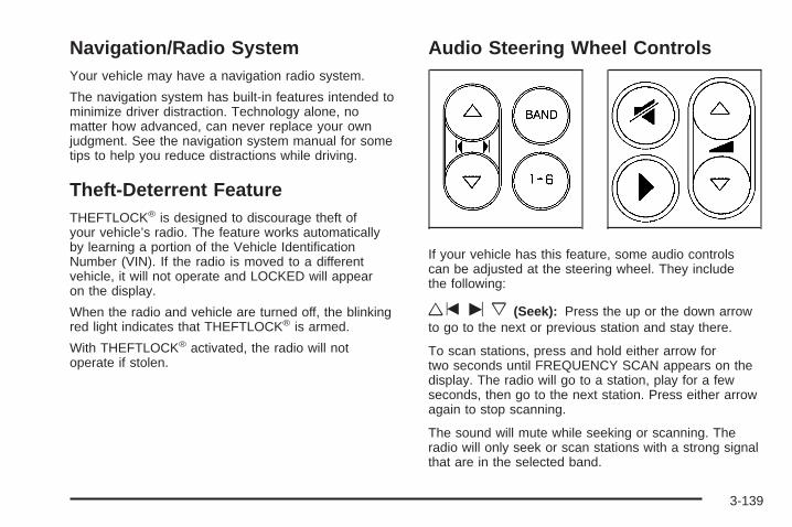
Navigation/Radio SystemYour vehicle may have a navigation radio system.
The navigation system has built-in features intended tominimize driver distraction. Technology alone, nomatter how advanced, can never replace your ownjudgment. See the navigation system manual for sometips to help you reduce distractions while driving.
Theft-Deterrent FeatureTHEFTLOCK® is designed to discourage theft ofyour vehicle’s radio. The feature works automaticallyby learning a portion of the Vehicle IdentificationNumber (VIN). If the radio is moved to a differentvehicle, it will not operate and LOCKED will appearon the display.
When the radio and vehicle are turned off, the blinkingred light indicates that THEFTLOCK® is armed.
With THEFTLOCK® activated, the radio will notoperate if stolen.
Audio Steering Wheel Controls
If your vehicle has this feature, some audio controlscan be adjusted at the steering wheel. They includethe following:
wtux (Seek): Press the up or the down arrowto go to the next or previous station and stay there.
To scan stations, press and hold either arrow fortwo seconds until FREQUENCY SCAN appears on thedisplay. The radio will go to a station, play for a fewseconds, then go to the next station. Press either arrowagain to stop scanning.
The sound will mute while seeking or scanning. Theradio will only seek or scan stations with a strong signalthat are in the selected band.
3-139

When a CD is playing, press either arrow to go to theprevious or next track, if more than eight seconds haveplayed. If either arrow is held or pressed more thanonce, the player will continue moving backwardor forward through the CD.
BAND: Press this button to switch between FM1, FM2,AM, or XM1 or XM2 (if equipped).
1 - 6: Press this button to scan the stations that areprogrammed on the radio preset pushbuttons. The radiowill go to the next preset station stored on thepushbuttons, play for a few seconds, then go on to thenext preset station. Press this button again to stopscanning. The radio will only scan preset stations with astrong signal that are in the selected band.
$ (Mute/OnStar ®): Press and release this button tosilence the audio system. Press it again, or anyother radio button to turn the sound on.
If your vehicle is equipped with OnStar, press and holdthis button to interact with the OnStar system. Seethe OnStar® System on page 2-38 in this manual formore information.
r (Play): When listening to the radio, press thisbutton to play a cassette tape or CD.
wux (Volume): Press the up or down arrow toincrease or decrease the volume.
Radio ReceptionYou may experience frequency interference and staticduring normal radio reception if items such as cellphonechargers, vehicle convenience accessories, andexternal electronic devices are plugged into theaccessory power outlet. If there is interference or static,unplug the item from the accessory power outlet.
AMThe range for most AM stations is greater than forFM, especially at night. The longer range can causestation frequencies to interfere with each other.For better radio reception, most AM radio stations willboost the power levels during the day, and then reducethese levels during the night. Static can also occurwhen things like storms and power lines interfere withradio reception. When this happens, try reducingthe treble on your radio.
FM StereoFM stereo will give the best sound, but FM signals willreach only about 10 to 40 miles (16 to 65 km). Tallbuildings or hills can interfere with FM signals, causingthe sound to fade in and out.
3-140

XM™ Satellite Radio ServiceXM™ Satellite Radio Service gives digital radioreception from coast-to-coast in the 48 contiguousUnited States, and in Canada (if available). Just as withFM, tall buildings or hills can interfere with satelliteradio signals, causing the sound to fade in and out. Inaddition, traveling or standing under heavy foliage,bridges, garages, or tunnels may cause loss of theXM™ signal for a period of time. The radio may displayNO SIGNAL to indicate interference.
Care of Your CDsHandle CDs carefully. Store them in their original casesor other protective cases and away from directsunlight and dust. The CD player scans the bottomsurface of the disc. If the surface of a CD is damaged,such as cracked, broken, or scratched, the CD willnot play properly or not at all. If the surface of a CD issoiled, take a soft, lint free cloth or dampen a clean, softcloth in a mild, neutral detergent solution mixed withwater, and clean it. Make sure the wiping process startsfrom the center to the edge.
Do not touch the bottom side of a CD while handling it;this could damage the surface. Pick up CDs bygrasping the outer edges or the edge of the hole andthe outer edge.
Care of the CD PlayerThe use of CD lens cleaners for CD players is notadvised, due to the risk of contaminating the internallens of the CD optics with lubricants.
Backglass AntennaThe AM-FM antenna is integrated with the rear windowdefogger, located in the rear window. Be sure that theinside surface of the rear window is not scratched andthat the lines on the glass are not damaged. If the insidesurface is damaged, it could interfere with radioreception. Also, for proper radio reception, the antennaconnector at the top-center of the rear window needs tobe properly attached to the post on the glass.
Notice: Using a razor blade or sharp object to clearthe inside rear window may damage the rear windowantenna and/or the rear window defogger. Repairswould not be covered by your warranty. Do not clearthe inside rear window with sharp objects.
Notice: Do not apply aftermarket glass tinting withmetallic film. The metallic film in some tintingmaterials will interfere with or distort the incomingradio reception. Any damage caused to yourbackglass antenna due to metallic tinting materialswill not be covered by your warranty.
3-141

Because this antenna is built into your rear window,there is a reduced risk of damage caused by car washesand vandals.
If you choose to add a cellular telephone to yourvehicle, and the antenna needs to be attached to theglass, be sure that you do not damage the grid lines forthe AM-FM antenna. There is enough space betweenthe lines to attach a cellular telephone antennawithout interfering with radio reception.
Do not apply aftermarket glass tinting to the back glass.The metallic film in some tinting materials will interferewith or distort the incoming radio reception. Caremust be taken when cleaning the rear window becauseit breaks in the resistive material heating elementand will adversely affect radio and defoggerperformance. See your dealer for details.
XM™ Satellite Radio AntennaSystemThe XM™ Satellite Radio antenna is located on the roofof your vehicle. Keep this antenna clear of snow andice build up for clear radio reception.
If your vehicle has a sunroof, the performance of theXM™ system may be affected if the sunroof is open.
Loading items onto the roof of your vehicle can interferewith the performance of the XM™ system. Make surethe XM™ Satellite Radio antenna is not obstructed.
Chime Level AdjustmentThe radio is used to adjust the vehicle’s chime level.To change the volume level of the chime, press and holdpushbutton 6 with the ignition on and the radio poweroff. The volume level will change from the normallevel to loud, and LOUD will appear on the radio display.To change back to the default or normal setting,press and hold pushbutton 6 again. The volume levelwill change from the loud level to normal, and NORMALwill appear on the radio display. Each time the chimevolume is changed, three chimes will sound as anexample of the new volume selected. Removing theradio and not replacing it with a factory radio or chimemodule will disable vehicle chimes.
3-142
Your Driving, the Road, and Your Vehicle ..........4-2Defensive Driving ...........................................4-2Drunken Driving .............................................4-3Control of a Vehicle ........................................4-5Braking .........................................................4-6Anti-Lock Brake System (ABS) .........................4-7Braking in Emergencies ...................................4-8Traction Control System (TCS) .........................4-9Enhanced Traction System (ETS) ....................4-11StabiliTrak® Plus System ...............................4-12Steering ......................................................4-13Off-Road Recovery .......................................4-16Passing .......................................................4-16Loss of Control .............................................4-18Driving at Night ............................................4-19
Driving in Rain and on Wet Roads ..................4-20City Driving ..................................................4-22Freeway Driving ...........................................4-23Before Leaving on a Long Trip .......................4-24Highway Hypnosis ........................................4-25Hill and Mountain Roads ................................4-26Winter Driving ..............................................4-28If Your Vehicle is Stuck in Sand, Mud,
Ice or Snow ..............................................4-32Rocking Your Vehicle to Get It Out .................4-33Loading Your Vehicle ....................................4-33
Towing ..........................................................4-38Towing Your Vehicle .....................................4-38Recreational Vehicle Towing ...........................4-38Towing a Trailer ...........................................4-40
Section 4 Driving Your Vehicle
4-1
Your Driving, the Road, andYour Vehicle
Defensive DrivingThe best advice anyone can give about driving is:Drive defensively.
Please start with a very important safety device in yourvehicle: Buckle up. See Safety Belts: They Are forEveryone on page 1-10.
{CAUTION:
Defensive driving really means “Be ready foranything.” On city streets, rural roads, orexpressways, it means “Always expect theunexpected.” Assume that pedestrians or otherdrivers are going to be careless and makemistakes. Anticipate what they might do andbe ready. Rear-end collisions are about themost preventable of accidents. Yet they arecommon. Allow enough following distance.Defensive driving requires that a driverconcentrate on the driving task. Anything thatdistracts from the driving task makes properdefensive driving more difficult and can evencause a collision, with resulting injury. Ask apassenger to help do these things, or pull offthe road in a safe place to do them. Thesesimple defensive driving techniques couldsave your life.
4-2
Drunken DrivingDeath and injury associated with drinking and driving isa national tragedy. It is the number one contributorto the highway death toll, claiming thousands of victimsevery year.
Alcohol affects four things that anyone needs to drivea vehicle:
• Judgment
• Muscular Coordination
• Vision
• Attentiveness
Police records show that almost half of all motorvehicle-related deaths involve alcohol. In most cases,these deaths are the result of someone who wasdrinking and driving. In recent years, more than16,000 annual motor vehicle-related deaths have beenassociated with the use of alcohol, with more than300,000 people injured.
Many adults — by some estimates, nearly half the adultpopulation — choose never to drink alcohol, so theynever drive after drinking. For persons under 21,it is against the law in every U.S. state to drink alcohol.There are good medical, psychological, anddevelopmental reasons for these laws.
The obvious way to eliminate the leading highwaysafety problem is for people never to drink alcohol andthen drive. But what if people do? How much is “toomuch” if someone plans to drive? It is a lot lessthan many might think. Although it depends on eachperson and situation, here is some general informationon the problem.
The Blood Alcohol Concentration (BAC) of someonewho is drinking depends upon four things:
• The amount of alcohol consumed
• The drinker’s body weight
• The amount of food that is consumed before andduring drinking
• The length of time it has taken the drinker toconsume the alcohol
4-3

According to the American Medical Association, a 180 lb(82 kg) person who drinks three 12 ounce (355 ml)bottles of beer in an hour will end up with a BACof about 0.06 percent. The person would reach thesame BAC by drinking three 4 ounce (120 ml) glassesof wine or three mixed drinks if each had 1-1/2 ounces(45 ml) of liquors like whiskey, gin, or vodka.
It is the amount of alcohol that counts. For example, ifthe same person drank three double martinis (3 ouncesor 90 ml of liquor each) within an hour, the person’s
BAC would be close to 0.12 percent. A person whoconsumes food just before or during drinking will have asomewhat lower BAC level.
There is a gender difference, too. Women generallyhave a lower relative percentage of body waterthan men. Since alcohol is carried in body water, thismeans that a woman generally will reach a higher BAClevel than a man of her same body weight will wheneach has the same number of drinks.
The law in most U.S. states, and throughout Canada,sets the legal limit at 0.08 percent. In some othercountries, the limit is even lower. For example, it is0.05 percent in both France and Germany. TheBAC limit for all commercial drivers in the United Statesis 0.04 percent.
The BAC will be over 0.10 percent after three tosix drinks (in one hour). Of course, as we have seen, itdepends on how much alcohol is in the drinks, andhow quickly the person drinks them.
But the ability to drive is affected well below a BAC of0.10 percent. Research shows that the driving skills ofmany people are impaired at a BAC approaching0.05 percent, and that the effects are worse at night. Alldrivers are impaired at BAC levels above 0.05 percent.
4-4

Statistics show that the chance of being in a collisionincreases sharply for drivers who have a BAC of0.05 percent or above. A driver with a BAC level of0.06 percent has doubled his or her chance of having acollision. At a BAC level of 0.10 percent, the chance ofthis driver having a collision is 12 times greater; at a levelof 0.15 percent, the chance is 25 times greater!
The body takes about an hour to rid itself of the alcohol inone drink. No amount of coffee or number of coldshowers will speed that up. “I will be careful” is not theright answer. What if there is an emergency, a need totake sudden action, as when a child darts into the street?A person with even a moderate BAC might not be able toreact quickly enough to avoid the collision.
There is something else about drinking and driving thatmany people do not know. Medical research shows thatalcohol in a person’s system can make crash injuriesworse, especially injuries to the brain, spinal cord, orheart. This means that when anyone who has beendrinking — driver or passenger — is in a crash, thatperson’s chance of being killed or permanently disabledis higher than if the person had not been drinking.
{CAUTION:
Drinking and then driving is very dangerous.Your reflexes, perceptions, attentiveness, andjudgment can be affected by even a smallamount of alcohol. You can have a serious — oreven fatal — collision if you drive after drinking.Please do not drink and drive or ride with adriver who has been drinking. Ride home in acab; or if you are with a group, designate adriver who will not drink.
Control of a VehicleYou have three systems that make your vehicle gowhere you want it to go. They are the brakes, thesteering, and the accelerator. All three systems have todo their work at the places where the tires meet the road.
4-5
Sometimes, as when you are driving on snow or ice, itis easy to ask more of those control systems thanthe tires and road can provide. That means you can losecontrol of your vehicle. See Traction Control System(TCS) on page 4-9 and Enhanced Traction System(ETS) on page 4-11.
Adding non-GM accessories can affect your vehicle’sperformance. See Accessories and Modificationson page 5-3.
BrakingSee Brake System Warning Light on page 3-42.
Braking action involves perception time andreaction time.
First, you have to decide to push on the brake pedal.That is perception time. Then you have to bring up yourfoot and do it. That is reaction time.
Average reaction time is about three-fourths of asecond. But that is only an average. It might be lesswith one driver and as long as two or three seconds ormore with another. Age, physical condition, alertness,coordination, and eyesight all play a part. So do alcohol,drugs, and frustration. But even in three-fourths of asecond, a vehicle moving at 60 mph (100 km/h) travels66 feet (20 m). That could be a lot of distance in anemergency, so keeping enough space betweenyour vehicle and others is important.
And, of course, actual stopping distances vary greatlywith the surface of the road, whether it is pavementor gravel; the condition of the road, whether it iswet, dry, or icy; tire tread; the condition of your brakes;the weight of the vehicle; and the amount of brakeforce applied.
Avoid needless heavy braking. Some people drivein spurts — heavy acceleration followed by heavybraking — rather than keeping pace with traffic. This is amistake. Your brakes may not have time to cool betweenhard stops. Your brakes will wear out much faster if youdo a lot of heavy braking. If you keep pace with the trafficand allow realistic following distances, you will eliminate alot of unnecessary braking. That means better brakingand longer brake life.
If your engine ever stops while you are driving, brakenormally but do not pump your brakes. If you do,the pedal may get harder to push down. If your enginestops, you will still have some power brake assist.But you will use it when you brake. Once the powerassist is used up, it may take longer to stop andthe brake pedal will be harder to push.
Adding non-GM accessories can affect your vehicle’sperformance. See Accessories and Modificationson page 5-3.
4-6

Anti-Lock Brake System (ABS)Your vehicle may have anti-lock brakes. ABS is anadvanced electronic braking system that will helpprevent a braking skid.
If your vehicle has anti-lockbrakes, this warning lighton the instrument panel willcome on briefly whenyou start your vehicle.
When you start your engine, or when you begin todrive away, your anti-lock brake system willcheck itself. You may hear a momentary motor orclicking noise while this test is going on, and you mayeven notice that your brake pedal moves orpulses a little. This is normal.
Let us say the road is wet and you are driving safely.Suddenly, an animal jumps out in front of you. You slamon the brakes and continue braking. Here is whathappens with ABS:
A computer senses that wheels are slowing down. Ifone of the wheels is about to stop rolling, the computerwill separately work the brakes at each wheel.
4-7

The anti-lock system can change the brake pressurefaster than any driver could. The computer isprogrammed to make the most of available tire and roadconditions. This can help you steer around the obstaclewhile braking hard.
As you brake, your computer keeps receiving updateson wheel speed and controls braking pressureaccordingly.
Remember: Anti-lock does not change the time youneed to get your foot up to the brake pedal or alwaysdecrease stopping distance. If you get too close tothe vehicle in front of you, you will not have time to applyyour brakes if that vehicle suddenly slows or stops.Always leave enough room up ahead to stop, eventhough you have anti-lock brakes.
Using Anti-LockDo not pump the brakes. Just hold the brake pedaldown firmly and let anti-lock work for you. You may feela slight brake pedal pulsation or notice some noise,but this is normal.
Braking in EmergenciesAt some time, nearly every driver gets into a situationthat requires hard braking.
If you have anti-lock brakes, you can steer and brake atthe same time. However, if you do not have anti-lockbrakes, your first reaction — to hit the brake pedal hardand hold it down — may be the wrong thing to do.Your wheels can stop rolling. Once they do, the vehiclecannot respond to your steering. Momentum willcarry it in whatever direction it was headed when thewheels stopped rolling. That could be off the road, intothe very thing you were trying to avoid, or into traffic.
4-8
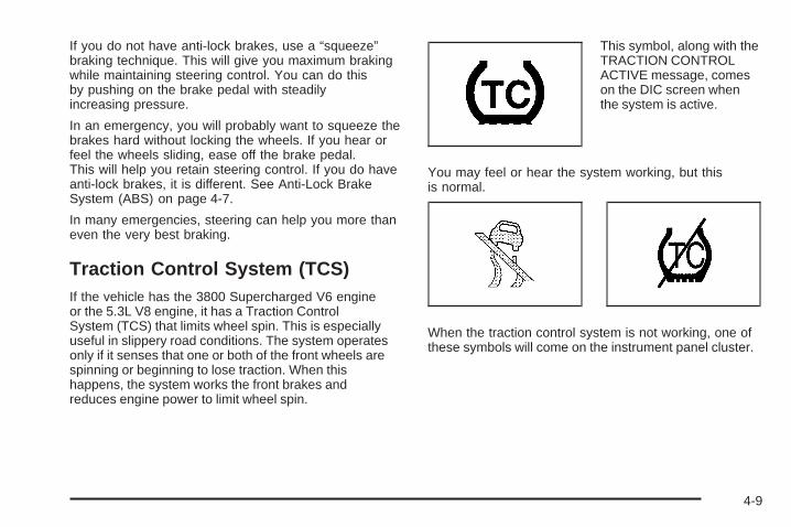
If you do not have anti-lock brakes, use a “squeeze”braking technique. This will give you maximum brakingwhile maintaining steering control. You can do thisby pushing on the brake pedal with steadilyincreasing pressure.
In an emergency, you will probably want to squeeze thebrakes hard without locking the wheels. If you hear orfeel the wheels sliding, ease off the brake pedal.This will help you retain steering control. If you do haveanti-lock brakes, it is different. See Anti-Lock BrakeSystem (ABS) on page 4-7.
In many emergencies, steering can help you more thaneven the very best braking.
Traction Control System (TCS)If the vehicle has the 3800 Supercharged V6 engineor the 5.3L V8 engine, it has a Traction ControlSystem (TCS) that limits wheel spin. This is especiallyuseful in slippery road conditions. The system operatesonly if it senses that one or both of the front wheels arespinning or beginning to lose traction. When thishappens, the system works the front brakes andreduces engine power to limit wheel spin.
This symbol, along with theTRACTION CONTROLACTIVE message, comeson the DIC screen whenthe system is active.
You may feel or hear the system working, but thisis normal.
When the traction control system is not working, one ofthese symbols will come on the instrument panel cluster.
4-9
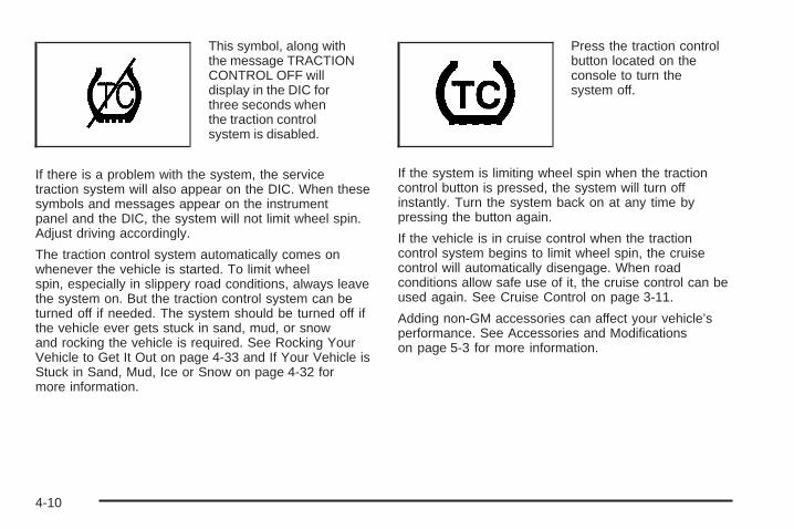
This symbol, along withthe message TRACTIONCONTROL OFF willdisplay in the DIC forthree seconds whenthe traction controlsystem is disabled.
If there is a problem with the system, the servicetraction system will also appear on the DIC. When thesesymbols and messages appear on the instrumentpanel and the DIC, the system will not limit wheel spin.Adjust driving accordingly.
The traction control system automatically comes onwhenever the vehicle is started. To limit wheelspin, especially in slippery road conditions, always leavethe system on. But the traction control system can beturned off if needed. The system should be turned off ifthe vehicle ever gets stuck in sand, mud, or snowand rocking the vehicle is required. See Rocking YourVehicle to Get It Out on page 4-33 and If Your Vehicle isStuck in Sand, Mud, Ice or Snow on page 4-32 formore information.
Press the traction controlbutton located on theconsole to turn thesystem off.
If the system is limiting wheel spin when the tractioncontrol button is pressed, the system will turn offinstantly. Turn the system back on at any time bypressing the button again.
If the vehicle is in cruise control when the tractioncontrol system begins to limit wheel spin, the cruisecontrol will automatically disengage. When roadconditions allow safe use of it, the cruise control can beused again. See Cruise Control on page 3-11.
Adding non-GM accessories can affect your vehicle’sperformance. See Accessories and Modificationson page 5-3 for more information.
4-10

Enhanced Traction System (ETS)If the vehicle has the 3800 V6 engine and anti-lockbrakes, it has an Enhanced Traction System (ETS) thatlimits wheel spin. This is especially useful in slipperyroad conditions. The system operates only if it sensesthat one or both of the front wheels are spinning orbeginning to lose traction. When this happens,the system reduces engine power and may also upshiftthe transaxle to limit wheel spin.
This symbol comes onthe Driver InformationCenter (DIC) whenthe ETS is limitingwheel spin.
If the vehicle is in cruise control when ETS begins tolimit wheel spin, the cruise control will automaticallydisengage. When road conditions allow safe use of it,the cruise control can be used again. See Cruise Controlon page 3-11.
ETS operates in all transaxle shift lever positions. Butthe system can upshift the transaxle only as high as thechosen shift lever position, so use the lower gearsonly when necessary. See Automatic TransaxleOperation on page 2-25.
One of these lights will appear on the instrument panelto indicate that the ETS is not on.
This symbol, along withthe message TRACTIONCONTROL OFF willdisplay on the DIC forthree seconds when theETS is not on.
If there is a problem with the system, the servicetraction system will also come on in the DIC. SeeEnhanced Traction System Warning Light on page 3-45.When this warning light is on, the system will not limitwheel spin. Adjust driving accordingly.
4-11

To limit wheel spin, especially in slippery roadconditions, the ETS should always be left on. But thesystem can be turned off. The system should be turnedoff if the vehicle ever gets stuck in sand, mud, orsnow and rocking the vehicle is required. See RockingYour Vehicle to Get It Out on page 4-33 and If YourVehicle is Stuck in Sand, Mud, Ice or Snow onpage 4-32 for more information.
Press the traction controlbutton located on theconsole to turn thesystem off.
If the system is limiting wheel spin when the button ispressed, the system will turn off instantly. Press thetraction control button again to turn the system on.
StabiliTrak ® Plus SystemThe vehicle may have a vehicle stability enhancementsystem called StabiliTrak® Plus. It is an advancedcomputer controlled system that assists with directionalcontrol of the vehicle in difficult driving conditions.
StabiliTrak® Plus comes on whenever the vehicle isstarted. It activates when the computer senses adiscrepancy between the intended path and the directionthe vehicle is actually traveling. StabiliTrak® Plusselectively applies braking pressure at any one of thevehicle’s brakes to help control the vehicle in thesteering direction.
This symbol, along withthe STABILITY CONTROLACTIVE message comeson the Driver InformationCenter (DIC).
See DIC Warnings and Messages on page 3-72. Youmay also hear a noise or feel vibration in the brakepedal. This is normal. Continue to steer the vehicle inthe desired direction.
4-12
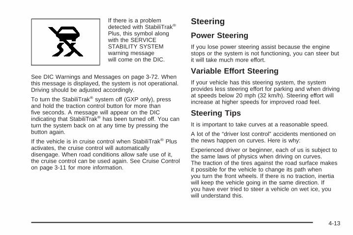
If there is a problemdetected with StabiliTrak®
Plus, this symbol alongwith the SERVICESTABILITY SYSTEMwarning messagewill come on the DIC.
See DIC Warnings and Messages on page 3-72. Whenthis message is displayed, the system is not operational.Driving should be adjusted accordingly.
To turn the StabiliTrak® system off (GXP only), pressand hold the traction control button for more thanfive seconds. A message will appear on the DICindicating that StabiliTrak® has been turned off. You canturn the system back on at any time by pressing thebutton again.
If the vehicle is in cruise control when StabiliTrak® Plusactivates, the cruise control will automaticallydisengage. When road conditions allow safe use of it,the cruise control can be used again. See Cruise Controlon page 3-11 for more information.
Steering
Power SteeringIf you lose power steering assist because the enginestops or the system is not functioning, you can steer butit will take much more effort.
Variable Effort SteeringIf your vehicle has this steering system, the systemprovides less steering effort for parking and when drivingat speeds below 20 mph (32 km/h). Steering effort willincrease at higher speeds for improved road feel.
Steering TipsIt is important to take curves at a reasonable speed.
A lot of the “driver lost control” accidents mentioned onthe news happen on curves. Here is why:
Experienced driver or beginner, each of us is subject tothe same laws of physics when driving on curves.The traction of the tires against the road surface makesit possible for the vehicle to change its path whenyou turn the front wheels. If there is no traction, inertiawill keep the vehicle going in the same direction. Ifyou have ever tried to steer a vehicle on wet ice, youwill understand this.
4-13
The traction you can get in a curve depends on thecondition of your tires and the road surface, the angle atwhich the curve is banked, and your speed. Whileyou are in a curve, speed is the one factor youcan control.
Suppose you are steering through a sharp curve.Then you suddenly apply the brakes. Both controlsystems — steering and braking — have to do theirwork where the tires meet the road. Unless youhave four-wheel anti-lock brakes, adding the hardbraking can demand too much of those places. Youcan lose control.
The same thing can happen if you are steering througha sharp curve and you suddenly accelerate. Thosetwo control systems — steering and acceleration — canoverwhelm those places where the tires meet theroad and make you lose control. See Traction ControlSystem (TCS) on page 4-9 or Enhanced TractionSystem (ETS) on page 4-11.
What should you do if this ever happens? Ease up onthe brake or accelerator pedal, steer the vehicle the wayyou want it to go, and slow down.
Speed limit signs near curves warn that you shouldadjust your speed. Of course, the posted speedsare based on good weather and road conditions. Underless favorable conditions you will want to go slower.
If you need to reduce your speed as you approacha curve, do it before you enter the curve, while your frontwheels are straight ahead.
Try to adjust your speed so you can “drive” through thecurve. Maintain a reasonable, steady speed. Wait toaccelerate until you are out of the curve, and thenaccelerate gently into the straightaway.
Adding non-GM accessories can affect your vehicle’sperformance. See Accessories and Modificationson page 5-3.
4-14

Steering in EmergenciesThere are times when steering can be more effectivethan braking. For example, you come over a hill and finda truck stopped in your lane, or a car suddenly pullsout from nowhere, or a child darts out from betweenparked cars and stops right in front of you. Youcan avoid these problems by braking — if you can stopin time. But sometimes you cannot; there is not room.That is the time for evasive action — steering aroundthe problem.
Your vehicle can perform very well in emergencies likethese. First apply your brakes.
See Braking on page 4-6. It is better to remove as muchspeed as you can from a possible collision. Thensteer around the problem, to the left or right dependingon the space available.
An emergency like this requires close attention and aquick decision. If you are holding the steering wheel atthe recommended 9 and 3 o’clock positions, youcan turn it a full 180 degrees very quickly withoutremoving either hand. But you have to act fast, steerquickly, and just as quickly straighten the wheelonce you have avoided the object.
The fact that such emergency situations are alwayspossible is a good reason to practice defensive drivingat all times and wear safety belts properly.
4-15

Off-Road RecoveryYou may find that your right wheels have droppedoff the edge of a road onto the shoulder while youare driving.
If the level of the shoulder is only slightly below thepavement, recovery should be fairly easy. Ease off theaccelerator and then, if there is nothing in the way,steer so that your vehicle straddles the edge ofthe pavement. You can turn the steering wheel up toone-quarter turn until the right front tire contactsthe pavement edge. Then turn your steering wheelto go straight down the roadway.
PassingThe driver of a vehicle about to pass another on atwo-lane highway waits for just the right moment,accelerates, moves around the vehicle ahead, thengoes back into the right lane again. A simple maneuver?
Not necessarily! Passing another vehicle on a two-lanehighway is a potentially dangerous move, since thepassing vehicle occupies the same lane as oncomingtraffic for several seconds. A miscalculation, an error injudgment, or a brief surrender to frustration or angercan suddenly put the passing driver face to face with theworst of all traffic accidents — the head-on collision.
So here are some tips for passing:
• Drive ahead. Look down the road, to the sidesand to crossroads for situations that mightaffect your passing patterns. If you have anydoubt whatsoever about making a successfulpass, wait for a better time.
• Watch for traffic signs, pavement markings andlines. If you can see a sign up ahead thatmight indicate a turn or an intersection, delay yourpass. A broken center line usually indicates itis all right to pass, providing the road ahead isclear. Never cross a solid line on your sideof the lane or a double solid line, even if the roadseems empty of approaching traffic.
4-16

• Do not get too close to the vehicle you want topass while you are awaiting an opportunity.For one thing, following too closely reduces yourarea of vision, especially if you are followinga larger vehicle. Also, you will not have adequatespace if the vehicle ahead suddenly slows orstops. Keep back a reasonable distance.
• When it looks like a chance to pass is coming up,start to accelerate but stay in the right lane anddo not get too close. Time your move soyou will be increasing speed as the time comes tomove into the other lane. If the way is clearto pass, you will have a running start that morethan makes up for the distance you wouldlose by dropping back. And if something happensto cause you to cancel your pass, you needonly slow down and drop back again and wait foranother opportunity.
• If other vehicles are lined up to pass a slow vehicle,wait your turn. But take care that someone is nottrying to pass you as you pull out to pass the slowvehicle. Remember to glance over your shoulder andcheck the blind spot.
• Check your mirrors, glance over your shoulder, andstart your left lane change signal before moving outof the right lane to pass. When you are far enoughahead of the passed vehicle to see its front in yourinside mirror, activate your right lane change signaland move back into the right lane. Remember thatyour passenger side outside mirror is convex. Thevehicle you just passed may seem to be farther awayfrom you than it really is.
• Try not to pass more than one vehicle at a time ontwo-lane roads. Reconsider before passing thenext vehicle.
• Do not overtake a slowly moving vehicle too rapidly.Even though the brake lamps are not flashing, it maybe slowing down or starting to turn.
• If you are being passed, make it easy for thefollowing driver to get ahead of you. Perhapsyou can ease a little to the right.
4-17

Loss of ControlLet us review what driving experts say about whathappens when the three control systems — brakes,steering, and acceleration — do not have enough frictionwhere the tires meet the road to do what thedriver has asked.In any emergency, do not give up. Keep trying tosteer and constantly seek an escape route or areaof less danger.
SkiddingIn a skid, a driver can lose control of the vehicle.Defensive drivers avoid most skids by taking reasonablecare suited to existing conditions, and by not overdrivingthose conditions. But skids are always possible.The three types of skids correspond to your vehicle’sthree control systems. In the braking skid, your wheelsare not rolling. In the steering or cornering skid, too muchspeed or steering in a curve causes tires to slip and losecornering force. And in the acceleration skid, too muchthrottle causes the driving wheels to spin.A cornering skid is best handled by easing your foot offthe accelerator pedal.If you do not have the Enhanced Traction System (ETS)or the Traction Control System (TCS), or if the systemis off, then an acceleration skid is also best handledby easing your foot off the accelerator pedal. SeeEnhanced Traction System (ETS) on page 4-11 orTraction Control System (TCS) on page 4-9.
If your vehicle starts to slide, ease your foot off theaccelerator pedal and quickly steer the way you wantthe vehicle to go. If you start steering quickly enough,your vehicle may straighten out. Always be readyfor a second skid if it occurs.
Of course, traction is reduced when water, snow, ice,gravel, or other material is on the road. For safety, youwill want to slow down and adjust your driving tothese conditions. It is important to slow down on slipperysurfaces because stopping distance will be longer andvehicle control more limited.
While driving on a surface with reduced traction, tryyour best to avoid sudden steering, acceleration,or braking, including engine braking by shifting to alower gear. Any sudden changes could cause the tiresto slide. You may not realize the surface is slipperyuntil your vehicle is skidding. Learn to recognize warningclues — such as enough water, ice, or packed snowon the road to make a mirrored surface — andslow down when you have any doubt.
If you have the Anti-Lock Brake System (ABS),remember: It helps avoid only the braking skid. If you donot have ABS, then in a braking skid, where thewheels are no longer rolling, release enough pressureon the brakes to get the wheels rolling again. Thisrestores steering control. Push the brake pedal downsteadily when you have to stop suddenly. As long as thewheels are rolling, you will have steering control.
4-18
Driving at NightNight driving is more dangerous than day driving.One reason is that some drivers are likely to beimpaired — by alcohol or drugs, with night visionproblems, or by fatigue.
Here are some tips on night driving.
• Drive defensively.
• Do not drink and drive.
• Adjust the inside rearview mirror to reduce the glarefrom headlamps behind you.
• Since you cannot see as well, you may need toslow down and keep more space between youand other vehicles.
• Slow down, especially on higher speed roads.Your vehicle’s headlamps can light up only somuch road ahead.
• In remote areas, watch for animals.
• If you are tired, pull off the road in a safe placeand rest.
No one can see as well at night as in the daytime. Butas we get older these differences increase. A50-year-old driver may require at least twice as muchlight to see the same thing at night as a 20-year-old.
What you do in the daytime can also affect your nightvision. For example, if you spend the day in brightsunshine you are wise to wear sunglasses. Your eyeswill have less trouble adjusting to night. But if youare driving, do not wear sunglasses at night. They maycut down on glare from headlamps, but they alsomake a lot of things invisible.
You can be temporarily blinded by approachingheadlamps. It can take a second or two, or even severalseconds, for your eyes to re-adjust to the dark. Whenyou are faced with severe glare, as from a driverwho does not lower the high beams, or a vehicle withmisaimed headlamps, slow down a little. Avoidstaring directly into the approaching headlamps.
Keep the windshield and all the glass on your vehicleclean — inside and out. Glare at night is made muchworse by dirt on the glass. Even the inside of the glasscan build up a film caused by dust. Dirty glass makeslights dazzle and flash more than clean glass would,making the pupils of your eyes contract repeatedly.
Remember that the headlamps light up far less of aroadway when you are in a turn or curve. Keepyour eyes moving; that way, it is easier to pick out dimlylighted objects. Just as the headlamps should bechecked regularly for proper aim, so should your eyesbe examined regularly. Some drivers suffer fromnight blindness — the inability to see in dim light — andare not even aware of it.
4-19
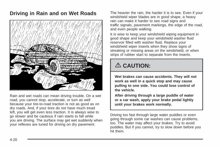
Driving in Rain and on Wet Roads
Rain and wet roads can mean driving trouble. On a wetroad, you cannot stop, accelerate, or turn as wellbecause your tire-to-road traction is not as good as ondry roads. And, if your tires do not have much treadleft, you will get even less traction. It is always wise togo slower and be cautious if rain starts to fall whileyou are driving. The surface may get wet suddenly whenyour reflexes are tuned for driving on dry pavement.
The heavier the rain, the harder it is to see. Even if yourwindshield wiper blades are in good shape, a heavyrain can make it harder to see road signs andtraffic signals, pavement markings, the edge of the road,and even people walking.It is wise to keep your windshield wiping equipment ingood shape and keep your windshield washer fluidreservoir filled with washer fluid. Replace yourwindshield wiper inserts when they show signs ofstreaking or missing areas on the windshield, or whenstrips of rubber start to separate from the inserts.
{CAUTION:
Wet brakes can cause accidents. They will notwork as well in a quick stop and may causepulling to one side. You could lose control ofthe vehicle.After driving through a large puddle of wateror a car wash, apply your brake pedal lightlyuntil your brakes work normally.
Driving too fast through large water puddles or evengoing through some car washes can cause problems,too. The water may affect your brakes. Try to avoidpuddles. But if you cannot, try to slow down before youhit them.
4-20

HydroplaningHydroplaning is dangerous. So much water can build upunder your tires that they can actually ride on thewater. This can happen if the road is wet enough andyou are going fast enough. When your vehicle ishydroplaning, it has little or no contact with the road.
Hydroplaning does not happen often. But it can if yourtires do not have much tread or if the pressure inone or more is low. It can happen if a lot of water isstanding on the road. If you can see reflectionsfrom trees, telephone poles, or other vehicles, andraindrops dimple the water’s surface, there couldbe hydroplaning.
Hydroplaning usually happens at higher speeds. Therejust is not a hard and fast rule about hydroplaning.The best advice is to slow down when it is raining.
Driving Through Deep Standing Water
Notice: If you drive too quickly through deeppuddles or standing water, water can come inthrough your engine’s air intake and badly damageyour engine. Never drive through water that isslightly lower than the underbody of your vehicle. Ifyou cannot avoid deep puddles or standing water,drive through them very slowly.
Driving Through Flowing Water
{CAUTION:
Flowing or rushing water creates strong forces.If you try to drive through flowing water, as youmight at a low water crossing, your vehicle canbe carried away. As little as six inches offlowing water can carry away a smaller vehicle.If this happens, you and other vehicleoccupants could drown. Do not ignore policewarning signs, and otherwise be very cautiousabout trying to drive through flowing water.
Some Other Rainy Weather Tips• Besides slowing down, allow some extra following
distance. And be especially careful when youpass another vehicle. Allow yourself more clearroom ahead, and be prepared to have yourview restricted by road spray.
• Have good tires with proper tread depth. See Tireson page 5-60.
4-21

City Driving
One of the biggest problems with city streets is theamount of traffic on them. You will want to watch out forwhat the other drivers are doing and pay attention totraffic signals.
Here are ways to increase your safety in city driving:
• Know the best way to get to where you aregoing. Get a city map and plan your trip intoan unknown part of the city just as you would for across-country trip.
• Try to use the freeways that rim and crisscrossmost large cities. You will save time and energy.See Freeway Driving on page 4-23.
• Treat a green light as a warning signal. A trafficlight is there because the corner is busy enoughto need it. When a light turns green, and just beforeyou start to move, check both ways for vehiclesthat have not cleared the intersection or maybe running the red light.
4-22

Freeway Driving
Mile for mile, freeways — also called thruways, parkways,expressways, turnpikes, or superhighways — are thesafest of all roads. But they have their own special rules.
The most important advice on freeway driving is:Keep up with traffic and keep to the right. Drive at thesame speed most of the other drivers are driving.Too-fast or too-slow driving breaks a smooth traffic flow.Treat the left lane on a freeway as a passing lane.
At the entrance, there is usually a ramp that leads to thefreeway. If you have a clear view of the freeway as youdrive along the entrance ramp, you should begin to checktraffic. Try to determine where you expect to blend withthe flow. Try to merge into the gap at close to theprevailing speed. Switch on your turn signal, check yourmirrors, and glance over your shoulder as often asnecessary. Try to blend smoothly with the traffic flow.
Once you are on the freeway, adjust your speed to theposted limit or to the prevailing rate if it is slower.Stay in the right lane unless you want to pass.
Before changing lanes, check your mirrors. Then useyour turn signal.
4-23

Just before you leave the lane, glance quickly over yourshoulder to make sure there is not another vehicle inyour blind spot.
Once you are moving on the freeway, make certain youallow a reasonable following distance.
Expect to move slightly slower at night.
When you want to leave the freeway, move to theproper lane well in advance. If you miss your exit, donot, under any circumstances, stop and back up. Driveon to the next exit.
The exit ramp can be curved, sometimes quite sharply.The exit speed is usually posted. Reduce your speedaccording to your speedometer, not to your senseof motion. After driving for any distance at higherspeeds, you may tend to think you are going slowerthan you actually are.
Before Leaving on a Long TripMake sure you are ready. Try to be well rested. If youmust start when you are not fresh — such as aftera day’s work — do not plan to make too many miles thatfirst part of the journey. Wear comfortable clothingand shoes you can easily drive in.
Is your vehicle ready for a long trip? If you keep itserviced and maintained, it is ready to go. If it needsservice, have it done before starting out. Of course,you will find experienced and able service experts inGM dealerships all across North America. They will beready and willing to help if you need it.
4-24

Here are some things you can check before a trip:
• Windshield Washer Fluid: Is the reservoir full? Areall windows clean inside and outside?
• Wiper Blades: Are they in good shape?
• Fuel, Engine Oil, Other Fluids: Have you checkedall levels?
• Lamps: Are they all working? Are the lenses clean?
• Tires: They are vitally important to a safe,trouble-free trip. Is the tread good enough forlong-distance driving? Are the tires all inflated to therecommended pressure?
• Weather Forecasts: What is the weather outlookalong your route? Should you delay your trip ashort time to avoid a major storm system?
• Maps: Do you have up-to-date maps?
Highway HypnosisIs there actually such a condition as highway hypnosis?Or is it just plain falling asleep at the wheel? Call ithighway hypnosis, lack of awareness, or whatever.
There is something about an easy stretch of road withthe same scenery, along with the hum of the tires on theroad, the drone of the engine, and the rush of thewind against the vehicle that can make you sleepy. Donot let it happen to you! If it does, your vehicle canleave the road in less than a second, and you couldcrash and be injured.
What can you do about highway hypnosis? First, beaware that it can happen.
Then here are some tips:
• Make sure your vehicle is well ventilated, with acomfortably cool interior.
• Keep your eyes moving. Scan the road ahead andto the sides. Check your rearview mirrors and yourinstruments frequently.
• If you get sleepy, pull off the road into a rest,service, or parking area and take a nap, get someexercise, or both. For safety, treat drowsinesson the highway as an emergency.
4-25
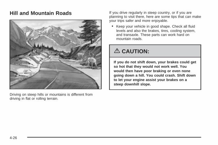
Hill and Mountain Roads
Driving on steep hills or mountains is different fromdriving in flat or rolling terrain.
If you drive regularly in steep country, or if you areplanning to visit there, here are some tips that can makeyour trips safer and more enjoyable.
• Keep your vehicle in good shape. Check all fluidlevels and also the brakes, tires, cooling system,and transaxle. These parts can work hard onmountain roads.
{CAUTION:
If you do not shift down, your brakes could getso hot that they would not work well. Youwould then have poor braking or even nonegoing down a hill. You could crash. Shift downto let your engine assist your brakes on asteep downhill slope.
4-26
{CAUTION:
Coasting downhill in NEUTRAL (N) or with theignition off is dangerous. Your brakes will haveto do all the work of slowing down. They couldget so hot that they would not work well. Youwould then have poor braking or even nonegoing down a hill. You could crash. Alwayshave your engine running and your vehicle ingear when you go downhill.
• Know how to go down hills. The most importantthing to know is this: let your engine do some ofthe slowing down. Shift to a lower gear when you godown a steep or long hill.
• Know how to go uphill. You may want to shift downto a lower gear. The lower gears help cool yourengine and transaxle, and you can climb thehill better.
• Stay in your own lane when driving on two-laneroads in hills or mountains. Do not swing wideor cut across the center of the road. Drive at speedsthat let you stay in your own lane.
• As you go over the top of a hill, be alert. Therecould be something in your lane, like a stalled car oran accident.
• You may see highway signs on mountains thatwarn of special problems. Examples are longgrades, passing or no-passing zones, a falling rocksarea, or winding roads. Be alert to these and takeappropriate action.
4-27

Winter Driving
Here are some tips for winter driving:
• Have your vehicle in good shape for winter.
• You may want to put winter emergency supplies inyour trunk.
Also see Tires on page 5-60.
Include an ice scraper, a small brush or broom, asupply of windshield washer fluid, a rag, some winterouter clothing, a small shovel, a flashlight, a redcloth, and a couple of reflective warning triangles. And,if you will be driving under severe conditions, includea small bag of sand, a piece of old carpet, or a couple ofburlap bags to help provide traction. Be sure youproperly secure these items in your vehicle.
4-28

Driving on Snow or IceMost of the time, those places where the tires meet theroad probably have good traction.
However, if there is snow or ice between the tires andthe road, you can have a very slippery situation. You willhave a lot less traction, or grip, and will need to bevery careful.
What is the worst time for this? Wet ice. Very cold snowor ice can be slick and hard to drive on. But wet icecan be even more trouble because it may offer the least
traction of all. You can get wet ice when it is aboutfreezing, 32°F (0°C), and freezing rain begins to fall. Tryto avoid driving on wet ice until salt and sand crewscan get there.
Whatever the condition — smooth ice, packed, blowing,or loose snow — drive with caution.
If you have the Traction Control System (TCS) or theEnhanced Traction System (ETS), it will improveyour ability to accelerate when driving on a slipperyroad. Even though your vehicle has a traction systemyou will want to slow down and adjust your driving to theroad conditions. Under certain conditions, you maywant to turn the TCS or ETS off, such as when drivingthrough deep snow and loose gravel, to help maintainvehicle motion at lower speeds. See Traction ControlSystem (TCS) on page 4-9 or Enhanced TractionSystem (ETS) on page 4-11.
If you do not have TCS or ETS, accelerate gently. Trynot to break the fragile traction. If you acceleratetoo fast, the drive wheels will spin and polish the surfaceunder the tires even more.
Unless you have the Anti-Lock Brake System (ABS),you will want to brake very gently, too. If you dohave ABS, see Anti-Lock Brake System (ABS) onpage 4-7. This system improves your vehicle’s stabilitywhen you make a hard stop on a slippery road.Whether you have ABS or not, you will want to beginstopping sooner than you would on dry pavement.
4-29

Without ABS, if you feel your vehicle begin to slide, letup on the brakes a little. Push the brake pedal downsteadily to get the most traction you can.
Remember, unless you have ABS, if you brake so hardthat your wheels stop rolling, you will just slide. Brakeso your wheels always keep rolling and you canstill steer.
• Whatever your braking system, allow greaterfollowing distance on any slippery road.
• Watch for slippery spots. The road might be fineuntil you hit a spot that is covered with ice. Onan otherwise clear road, ice patches may appear inshaded areas where the sun cannot reach, suchas around clumps of trees, behind buildings,or under bridges. Sometimes the surface of a curveor an overpass may remain icy when thesurrounding roads are clear. If you see a patch ofice ahead of you, brake before you are on it. Try notto brake while you are actually on the ice, andavoid sudden steering maneuvers.
If You Are Caught in a BlizzardIf you are stopped by heavy snow, you could be in aserious situation. You should probably stay withyour vehicle unless you know for sure that you are nearhelp and you can hike through the snow. Here aresome things to do to summon help and keep yourselfand your passengers safe:
• Turn on your hazard flashers.
• Tie a red cloth to your vehicle to alert police thatyou have been stopped by the snow.
• Put on extra clothing or wrap a blanket around you.If you do not have blankets or extra clothing, makebody insulators from newspapers, burlap bags,rags, floor mats — anything you can wrap aroundyourself or tuck under your clothing to keep warm.
4-30
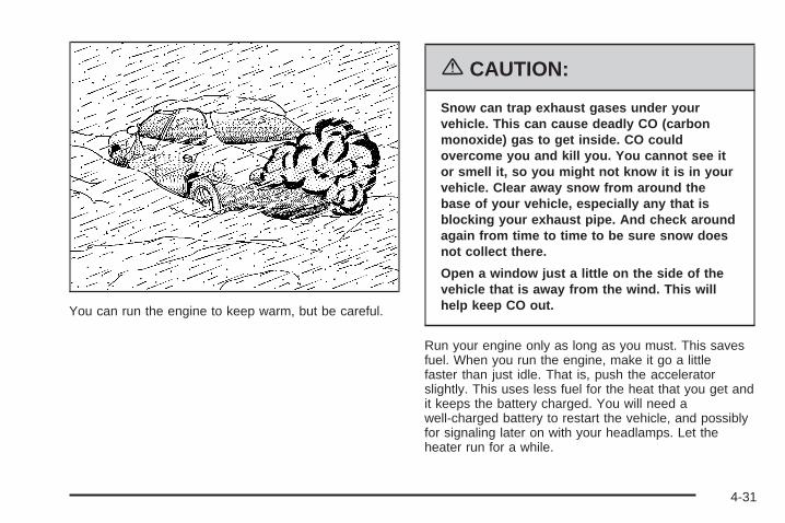
You can run the engine to keep warm, but be careful.
{CAUTION:
Snow can trap exhaust gases under yourvehicle. This can cause deadly CO (carbonmonoxide) gas to get inside. CO couldovercome you and kill you. You cannot see itor smell it, so you might not know it is in yourvehicle. Clear away snow from around thebase of your vehicle, especially any that isblocking your exhaust pipe. And check aroundagain from time to time to be sure snow doesnot collect there.
Open a window just a little on the side of thevehicle that is away from the wind. This willhelp keep CO out.
Run your engine only as long as you must. This savesfuel. When you run the engine, make it go a littlefaster than just idle. That is, push the acceleratorslightly. This uses less fuel for the heat that you get andit keeps the battery charged. You will need awell-charged battery to restart the vehicle, and possiblyfor signaling later on with your headlamps. Let theheater run for a while.
4-31
Then, shut the engine off and close the window almostall the way to preserve the heat. Start the engineagain and repeat this only when you feel reallyuncomfortable from the cold. But do it as little aspossible. Preserve the fuel as long as you can. To helpkeep warm, you can get out of the vehicle and dosome fairly vigorous exercises every half hour or so untilhelp comes.
If Your Vehicle is Stuck in Sand,Mud, Ice or SnowIn order to free your vehicle when it is stuck, you willneed to spin the wheels, but you do not want tospin your wheels too fast. The method known as rockingcan help you get out when you are stuck, but youmust use caution.
{CAUTION:
If you let your tires spin at high speed, they canexplode, and you or others could be injured.And, the transaxle or other parts of the vehiclecan overheat. That could cause an enginecompartment fire or other damage. When youare stuck, spin the wheels as little as possible.Do not spin the wheels above 35 mph (55 km/h)as shown on the speedometer.
Notice: Spinning your wheels can destroy parts ofyour vehicle as well as the tires. If you spin thewheels too fast while shifting your transaxle backand forth, you can destroy your transaxle. SeeRocking Your Vehicle to Get It Out on page 4-33.
For information about using tire chains on your vehicle,see Tire Chains on page 5-77.
4-32

Rocking Your Vehicle to Get It OutFirst, turn your steering wheel left and right. That willclear the area around your front wheels. If your vehiclehas traction control, you should turn your traction controlsystem off. See Traction Control System (TCS) onpage 4-9. Then shift back and forth betweenREVERSE (R) and a forward gear, spinning the wheelsas little as possible. Release the accelerator pedal whileyou shift, and press lightly on the accelerator pedal whenthe transaxle is in gear. By slowly spinning your wheels inthe forward and reverse directions, you will cause arocking motion that may free your vehicle. If that does notget you out after a few tries, you may need to be towedout. If you do need to be towed out, see Towing YourVehicle on page 4-38.
Loading Your VehicleIt is very important to know how much weight yourvehicle can carry. Two labels on your vehicle showhow much weight it may properly carry, the Tireand Loading Information label and the VehicleCertification label.
{CAUTION:
Do not load your vehicle any heavier than theGross Vehicle Weight Rating (GVWR), or eitherthe maximum front or rear Gross Axle WeightRating (GAWR). If you do, parts on yourvehicle can break, and it can change the wayyour vehicle handles. These could cause youto lose control and crash. Also, overloadingcan shorten the life of your vehicle.
4-33

Tire and Loading Information Label
A vehicle specific Tire and Loading Information label isattached to the vehicle’s center pillar (B-pillar). Withthe driver’s door open, you will find the label attachedbelow the door lock post (striker). The tire andloading information label lists the number of occupantseating positions (A), and the maximum vehicle capacityweight (B) in kilograms and pounds.
The Tire and Loading Information label also lists the tiresize of the original equipment tires (C) and therecommended cold tire inflation pressures (D). For moreinformation on tires and inflation, see Tires onpage 5-60 and Inflation - Tire Pressure on page 5-67.
There is also important loading information on theCertification label. It tells you the Gross Vehicle WeightRating (GVWR) and the Gross Axle Weight Rating(GAWR) for the front and rear axle, see “CertificationLabel” later in this section.
Steps for Determining Correct Load Limit1. Locate the statement “The combined weight
of occupants and cargo should never exceedXXX kg or XXX lbs” on your vehicle’s placard.
2. Determine the combined weight of the driver andpassengers that will be riding in your vehicle.
3. Subtract the combined weight of the driver andpassengers from XXX kg or XXX lbs.
Label Example
4-34

4. The resulting figure equals the available amount ofcargo and luggage load capacity. For example, ifthe “XXX” amount equals 1400 lbs and there will befive 150 lb passengers in your vehicle, the amountof available cargo and luggage load capacity is650 lbs (1400 − 750 (5 x 150) = 650 lbs).
5. Determine the combined weight of luggage andcargo being loaded on the vehicle. That weightmay not safely exceed the available cargoand luggage load capacity calculated in Step 4.
6. If your vehicle will be towing a trailer, the load fromyour trailer will be transferred to your vehicle.Consult this manual to determine how this reducesthe available cargo and luggage load capacityfor your vehicle.
If your vehicle can tow a trailer, see Towing a Trailer onpage 4-40 for important information on towing atrailer, towing safety rules, and trailering tips.
Item Description Total
AMaximum VehicleCapacity Weight forExample 1 =
1,000 lbs (453 kg)
BSubtract OccupantWeight 150 lbs(68 kg) × 2 =
300 lbs (136 kg)
C Available Occupant andCargo Weight = 700 lbs (317 kg)
Example 1
4-35

Item Description Total
AMaximum VehicleCapacity Weight forExample 2 =
1,000 lbs (453 kg)
BSubtract OccupantWeight 150 lbs(68 kg) × 5 =
750 lbs (340 kg)
C AvailableCargo Weight = 250 lbs (113 kg)
Item Description Total
AMaximum VehicleCapacity Weight forExample 3 =
1,000 lbs (453 kg)
BSubtract OccupantWeight 200 lbs(91 kg) × 5 =
1,000 lbs (453 kg)
C AvailableCargo Weight = 0 lbs (0 kg)
Refer to your vehicle’s tire and loading information labelfor specific information about your vehicle’s maximumvehicle capacity weight and seating positions. Thecombined weight of the driver, passengers, and cargoshould never exceed your vehicle’s maximum vehiclecapacity weight.
Example 2 Example 3
4-36

Certification Label
A vehicle specific Certification label is found on the rearedge of the driver’s door.
The label shows the gross weight capacity of yourvehicle, called the Gross Vehicle Weight Rating(GVWR). The GVWR includes the weight of the vehicle,all occupants, fuel, and cargo.
Never exceed the GVWR for your vehicle or the GrossAxle Weight Rating (GAWR) for either the front orrear axle.
If the vehicle is going to carry a heavy load, spread itout. Do not carry more than 167 lbs (76 kg) in the trunk.
{CAUTION:
Do not load your vehicle any heavier than theGross Vehicle Weight Rating (GVWR), or eitherthe maximum front or rear Gross Axle WeightRating (GAWR). If you do, parts on yourvehicle can break, and it can change the wayyour vehicle handles. These could cause youto lose control and crash. Also, overloadingcan shorten the life of your vehicle.
Notice: Overloading your vehicle may causedamage. Repairs would not be covered by yourwarranty. Do not overload your vehicle.
4-37

If things like suitcases, tools, packages, or anything elseare put inside the vehicle, they will go as fast as thevehicle goes. If you have to stop or turn quickly,or if there is a crash, they will keep going.
{CAUTION:
Things you put inside your vehicle can strikeand injure people in a sudden stop or turn, orin a crash.
• Put things in the trunk of your vehicle. In atrunk, put them as far forward as you can.Try to spread the weight evenly.
• Never stack heavier things, like suitcases,inside the vehicle so that some of themare above the tops of the seats.
• Do not leave an unsecured child restraintin your vehicle.
• When you carry something inside thevehicle, secure it whenever you can.
• Do not leave a seat folded down unlessyou need to.
Towing
Towing Your VehicleConsult your dealer or a professional towing service ifyou need to have your disabled vehicle towed. SeeRoadside Assistance Program on page 7-6.
If you want to tow your vehicle behind another vehiclefor recreational purposes (such as behind a motorhome),see “Recreational Vehicle Towing” following.
Recreational Vehicle TowingRecreational vehicle towing means towing your vehiclebehind another vehicle – such as behind a motorhome.The two most common types of recreational vehicletowing are known as dinghy towing, towing your vehiclewith all four wheels on the ground, and dolly towing,towing your vehicle with two wheels on the ground andtwo wheels up on a device known as a dolly.
With the proper preparation and equipment, manyvehicles can be towed in these ways. See “DinghyTowing” and “Dolly Towing,” following.
4-38

Here are some important things to consider before youdo recreational vehicle towing:
• What is the towing capacity of the towing vehicle?Be sure to read the tow vehicle manufacturer’srecommendations.
• How far will the vehicle be towed? Some vehicleshave restrictions on how far and how long theycan tow.
• Do you have the proper towing equipment? Seeyour dealer or trailering professional for additionaladvice and equipment recommendations.
• Is the vehicle ready to be towed? Just as you wouldprepare your vehicle for a long trip, you will want tomake sure the vehicle is prepared to be towed.See Before Leaving on a Long Trip on page 4-24.
Dinghy Towing
Notice: If you tow your vehicle with all four wheelson the ground, the drivetrain components couldbe damaged. The repairs would not be covered byyour warranty. Do not tow your vehicle with allfour wheels on the ground.
The vehicle was not designed to be towed with allfour wheels on the ground. If the vehicle must betowed, use a dolly. See “Dolly Towing” following formore information.
Dolly Towing
The vehicle can be towed using a dolly. To tow yourvehicle using a dolly, follow these steps:
1. Put the front wheels on the dolly.
2. Put the vehicle in PARK (P).
3. Set the parking brake and then remove the key.
4. Clamp the steering wheel in a straight-aheadposition.
5. Release the parking brake.
4-39
Towing a Trailer
{CAUTION:
If you do not use the correct equipment anddrive properly, you can lose control when youpull a trailer. For example, if the trailer is tooheavy, the brakes may not work well — or evenat all. You and your passengers could beseriously injured. You may also damage yourvehicle; the resulting repairs would not becovered by your warranty. Pull a trailer only ifyou have followed all the steps in this section.Ask your dealer for advice and informationabout towing a trailer with your vehicle.
The vehicle can tow a trailer if it is equipped with theproper trailer towing equipment. To identify the traileringcapacity of the vehicle, read the information in “Weightof the Trailer” that appears later in this section. Traileringis different than just driving the vehicle by itself.Trailering means changes in handling, durability, andfuel economy. Successful, safe trailering takes correctequipment, and it has to be used properly.
That is the reason for this part. In it are manytime-tested, important trailering tips and safety rules.Many of these are important for your safety and that ofyour passengers. So please read this section carefullybefore pulling a trailer.
Load-pulling components such as the engine, transaxle,wheel assemblies, and tires are forced to work harderagainst the drag of the added weight. The engineis required to operate at relatively higher speeds andunder greater loads, generating extra heat. Thetrailer also adds considerably to wind resistance,increasing the pulling requirements.
4-40

If You Do Decide To Pull A TrailerHere are some important points:
• There are many different laws, including speed limitrestrictions, having to do with trailering. Make sureyour rig will be legal, not only where you livebut also where you will be driving. A good sourcefor this information can be state or provincial police.
• Consider using a sway control. Ask a hitchdealer about sway controls.
• Do not tow a trailer at all during the first 1,000 miles(1 600 km) the new vehicle is driven. The engine,axle, or other parts could be damaged.
• Then, during the first 500 miles (800 km) that thevehicle tows a trailer, do not drive over 50 mph(80 km/h) and do not make starts at full throttle. Thishelps the engine and other parts of the vehiclewear in at the heavier loads.
• Obey speed limit restrictions when towing a trailer.Do not drive faster than the maximum postedspeed for trailers, or no more than 55 mph(90 km/h), to save wear on the vehicle’s parts.
Three important considerations have to do with weight:
• The weight of the trailer
• The weight of the trailer tongue
• The total weight on your vehicle’s tires
Weight of the TrailerHow heavy can a trailer safely be?It should never weigh more than 1,000 lbs (454 kg). Buteven that can be too heavy.
It depends on how you plan to use your rig. Forexample, speed, altitude, road grades, outsidetemperature, and how much the vehicle is used to pull atrailer are all important. It can also depend on any specialequipment that is on the vehicle, and the amount oftongue weight the vehicle can carry. See “Weight of theTrailer Tongue” later in this section for more information.
Maximum trailer weight is calculated assuming only thedriver is in the tow vehicle and it has all the requiredtrailering equipment. The weight of additional optionalequipment, passengers and cargo in the tow vehiclemust be subtracted from the maximum trailer weight.
Ask your dealer for our trailering information or advice,or write us at:
Pontiac-GMC Customer Assistance CenterP.O. Box 33172Detroit, MI 48232-5172
In Canada, write to:
General Motors of Canada LimitedCustomer Communication Centre, 163-0051908 Colonel Sam DriveOshawa, Ontario L1H 8P7
4-41

Weight of the Trailer TongueThe tongue load (A) of any trailer is an important weightto measure because it affects the total or gross weightof the vehicle. The Gross Vehicle Weight (GVW)includes the curb weight of the vehicle, any cargo in it,and the people who will be riding in the vehicle. Ifthere are a lot of options, equipment, passengers andcargo in the vehicle, it will reduce the tongue weight thevehicle can carry, which will also reduce the trailerweight the vehicle can tow. And if towing a trailer, thetongue load must be added to the GVW becausethe vehicle will be carrying that weight, too. See LoadingYour Vehicle on page 4-33 for more information aboutyour vehicle’s maximum load capacity.
When using a weight-carrying hitch or aweight-distributing hitch, the trailer tongue (A) shouldweigh 10 to 15 percent of the total loaded trailerweight (B).
After the trailer is loaded, weigh the trailer and then thetongue, separately, to see if the weights are proper.The correct weight could be achieved simply by movingsome items around in the trailer.
4-42

Total Weight on Your Vehicle’s TiresBe sure the vehicle’s tires are inflated to the upper limitfor cold tires. These numbers can be found on theTire Loading Information label, that is on the inside ofthe trunk lid. See Loading Your Vehicle on page 4-33.Be sure not to go over the GVW limit for the vehicle, orthe GAWR, including the weight of the trailer tongue.If a weight distribution hitch is used, make sure not to goover the rear axle limit before applying the weightdistribution spring bars.
HitchesIt is important to have the correct hitch equipment.Crosswinds, large trucks going by, and rough roads area few reasons why the correct hitch is needed. Hereare some rules to follow:
• The rear bumper on the vehicle is not intended forhitches. Do not attach rental hitches or otherbumper-type hitches to it. Use only a frame-mountedhitch that does not attach to the bumper.
• If any holes need to be made in the body of thevehicle to install a trailer hitch, then be sure to sealthe holes later when the hitch is removed. If the holesare not sealed, deadly carbon monoxide (CO) fromthe exhaust can get into the vehicle. See EngineExhaust on page 2-33. Dirt and water can, too.
Safety ChainsAlways attach chains between the vehicle and thetrailer. Cross the safety chains under the tongue of thetrailer so that the tongue will not drop to the road ifit becomes separated from the hitch. Instructions aboutsafety chains may be provided by the hitch manufactureror by the trailer manufacturer. Follow the manufacturer’srecommendation for attaching safety chains and donot attach them to the bumper. Always leave justenough slack so the rig can be turned around. And,never allow safety chains to drag on the ground.
Trailer BrakesBecause the vehicle has anti-lock brakes, do not try totap into the vehicle’s brake system. If this is done,both brake systems will not work well, or at all.
Driving with a TrailerTowing a trailer requires a certain amount of experience.Before setting out for the open road, get to know the rig.Acquaint yourself with the feel of handling and brakingwith the added weight of the trailer. And always keep inmind that the vehicle is now a good deal longer and notnearly as responsive as the vehicle is by itself.
4-43

Before starting, check the trailer hitch and platform (andattachments), safety chains, electrical connector,lamps, tires, and mirror adjustment. If the trailer haselectric brakes, start the vehicle and trailer moving andthen apply the trailer brake controller by hand to besure the brakes are working. This lets you checkthe electrical connection at the same time.
During your trip, check occasionally to be sure that theload is secure, and that the lamps and any trailerbrakes are still working.
Following DistanceStay at least twice as far behind the vehicle ahead aswhen driving the vehicle without a trailer. This canprevent situations that require heavy braking andsudden turns.
PassingMore passing distance is needed up ahead whentowing a trailer. And, because the vehicle and trailer area good deal longer, distances between any vehiclesthat are passed must be greater, before returning tothe proper lane.
Backing UpHold the bottom of the steering wheel with one hand.Then, to move the trailer to the left, move that handto the left. To move the trailer to the right, move thathand to the right. Always back up slowly and, if possible,have someone guide you.
Making Turns
Notice: Making very sharp turns while traileringcould cause the trailer to come in contact with thevehicle. Your vehicle could be damaged. Avoidmaking very sharp turns while trailering.
When turning with a trailer, make wider turns thannormal. Do this so the trailer will not strike softshoulders, curbs, road signs, trees, or other objects.Avoid jerky or sudden maneuvers. Signal wellin advance.
Turn Signals When Towing a TrailerWhen towing a trailer, the vehicle may need a differentturn signal flasher and/or extra wiring. Check withyour dealer. The arrows on the instrument panel willflash whenever signaling a turn or lane change. Properlyhooked up, the trailer lamps will also flash, tellingother drivers the vehicle and trailer are about to turn,change lanes, or stop.
4-44

When towing a trailer, the arrows on the instrumentpanel will flash for turns even if the bulbs on the trailerare burned out. You may think drivers behind youare seeing the turn signal when they are not. It isimportant to check occasionally to be sure the trailerbulbs are still working.
The vehicle has bulb warning lights. When a trailerlighting system is plugged into the vehicle’s lightingsystem, its bulb warning lights may not indicate if one ofthe lamps goes out. So, when a trailer lighting systemis plugged in, be sure to check the vehicle andtrailer lamps from time to time to be sure they are allworking. Once the trailer lamps have been disconnected,the bulb warning lights can once again indicate ifone of the vehicle lamps is out.
Driving On GradesReduce speed and shift to a lower gear before startingdown a long or steep downgrade. If the vehicle isnot shifted down, the brakes may have to be used somuch that they would get hot and no longer work well.
On a long uphill grade, shift down and reduce thevehicle’s speed to around 45 mph (70 km/h) to reducethe possibility of engine and transaxle overheating.
If the vehicle has overdrive, it may be driven inTHIRD (3) instead of AUTOMATIC OVERDRIVE (D).
Parking on Hills
{CAUTION:
You really should not park your vehicle, with atrailer attached, on a hill. If something goeswrong, your rig could start to move. Peoplecan be injured, and both your vehicle and thetrailer can be damaged.
But if the rig ever has to be parked on a hill, here ishow to do it:
1. Apply the regular brakes, but do not shift intoPARK (P) yet.
2. Have someone place chocks under thetrailer wheels.
3. When the wheel chocks are in place, release theregular brakes until the chocks absorb the load.
4. Reapply the regular brakes. Then apply the parkingbrake, and then shift to PARK (P).
5. Release the regular brakes.
4-45

When You Are Ready to Leave AfterParking on a Hill
1. Apply the regular brakes and hold the pedal downwhile you:
• Start the engine
• Shift into a gear
• Release the parking brake
2. Let up on the brake pedal.
3. Drive slowly until the trailer is clear of the chocks.
4. Stop and have someone pick up and storethe chocks.
Maintenance When Trailer TowingThe vehicle will need service more often when it pulls atrailer. See Scheduled Maintenance on page 6-4 formore information. Things that are especially important intrailer operation are automatic transaxle fluid, whichshould not be overfilled, engine oil, drive belts, cooling,and brake systems. Each of these is covered in thismanual, and the Index will help locate them quickly. Iftrailering, it is a good idea to review this informationbefore starting on a trip.
Check periodically to see that all hitch nuts and boltsare tight.
Engine Cooling When Trailer TowingThe cooling system may temporarily overheat duringsevere operating conditions. See Engine Overheating onpage 5-28.
4-46

Service ............................................................5-3Accessories and Modifications ..........................5-3California Proposition 65 Warning .....................5-3Doing Your Own Service Work .........................5-4Adding Equipment to the Outside of
Your Vehicle ..............................................5-5Fuel ................................................................5-5
Gasoline Octane ............................................5-5Gasoline Specifications ....................................5-5California Fuel ...............................................5-6Additives .......................................................5-6Fuels in Foreign Countries ...............................5-7Filling the Tank ..............................................5-7Filling a Portable Fuel Container .......................5-9
Checking Things Under the Hood ....................5-10Hood Release ..............................................5-11Engine Compartment Overview .......................5-12Engine Oil ...................................................5-16Engine Oil Life System ..................................5-19Supercharger Oil ..........................................5-20Engine Air Cleaner/Filter ................................5-21Automatic Transaxle Fluid ..............................5-23Engine Coolant .............................................5-25Pressure Cap ...............................................5-28Engine Overheating .......................................5-28
Overheated Engine ProtectionOperating Mode ........................................5-30
Cooling System ............................................5-30Power Steering Fluid .....................................5-40Windshield Washer Fluid ................................5-41Brakes ........................................................5-42Battery ........................................................5-45Jump Starting ...............................................5-46
Headlamp Aiming ...........................................5-50Bulb Replacement ..........................................5-53
Halogen Bulbs ..............................................5-53Headlamps and Sidemarker Lamps .................5-54Front Turn Signal, Parking and Fog Lamps ......5-56Taillamps, Turn Signal, and Stoplamps ............5-57Back-Up Lamps ............................................5-58Replacement Bulbs .......................................5-59
Windshield Replacement .................................5-60Windshield Wiper Blade Replacement ..............5-60Tires ..............................................................5-60
Tire Sidewall Labeling ...................................5-62Tire Terminology and Definitions .....................5-64Inflation - Tire Pressure .................................5-67Tire Inflation Monitor System ..........................5-68Tire Inspection and Rotation ...........................5-70
Section 5 Service and Appearance Care
5-1

When It Is Time for New Tires .......................5-71Buying New Tires .........................................5-72Different Size Tires and Wheels ......................5-73Uniform Tire Quality Grading ..........................5-74Wheel Alignment and Tire Balance ..................5-75Wheel Replacement ......................................5-75Tire Chains ..................................................5-77If a Tire Goes Flat ........................................5-77Tire Inflator Kit (GXP) ....................................5-79Changing a Flat Tire .....................................5-88Removing the Spare Tire and Tools ................5-90Removing the Flat Tire and Installing
the Spare Tire ..........................................5-91Storing a Flat or Spare Tire and Tools ............5-97Compact Spare Tire ......................................5-99
Appearance Care ............................................5-99Cleaning the Inside of Your Vehicle .................5-99Fabric/Carpet ..............................................5-101Leather ......................................................5-103Ultra Lux Suede ..........................................5-103Instrument Panel, Vinyl, and Other
Plastic Surfaces .......................................5-104Care of Safety Belts ....................................5-104Weatherstrips .............................................5-104
Washing Your Vehicle ..................................5-105Cleaning Exterior Lamps/Lenses ....................5-105Finish Care ................................................5-105Windshield and Wiper Blades .......................5-106Aluminum Wheels .......................................5-106Tires .........................................................5-107Sheet Metal Damage ...................................5-107Finish Damage ...........................................5-107Underbody Maintenance ...............................5-108Chemical Paint Spotting ...............................5-108Vehicle Care/Appearance Materials ................5-109
Vehicle Identification .....................................5-110Vehicle Identification Number (VIN) ................5-110Service Parts Identification Label ...................5-110
Electrical System ..........................................5-111Add-On Electrical Equipment .........................5-111Headlamp Wiring ........................................5-111Windshield Wiper Fuses ...............................5-111Power Windows and Other Power Options ......5-111Fuses and Circuit Breakers ..........................5-112Instrument Panel Fuse Block ........................5-112Underhood Fuse Block ................................5-114
Capacities and Specifications ........................5-118
Section 5 Service and Appearance Care
5-2
ServiceYour dealer knows your vehicle best and wants you tobe happy with it. We hope you will go to your dealerfor all your service needs. You will get genuine GM partsand GM-trained and supported service people.
We hope you will want to keep your GM vehicle all GM.Genuine GM parts have one of these marks:
Accessories and ModificationsWhen you add non-GM accessories to your vehicle theycan affect your vehicle’s performance and safety,including such things as, braking, stability, ride andhandling, emissions systems, aerodynamics, durability,and electronic systems like antilock brakes, tractioncontrol and stability control. Some of these accessoriesmay even cause malfunction or damage not coveredby warranty.
GM Accessories are designed to complement andfunction with other systems on your vehicle. YourGM dealer can accessorize your vehicle using genuineGM Accessories. When you go to your GM dealerand ask for GM Accessories, you will know thatGM-trained and supported service technicians willperform the work using genuine GM Accessories.
California Proposition 65 WarningMost motor vehicles, including this one, contain and/oremit chemicals known to the State of California tocause cancer and birth defects or other reproductiveharm. Engine exhaust, many parts and systems(including some inside the vehicle), many fluids, andsome component wear by-products contain and/or emitthese chemicals.
5-3
Doing Your Own Service Work
{CAUTION:
You can be injured and your vehicle could bedamaged if you try to do service work on avehicle without knowing enough about it.
• Be sure you have sufficient knowledge,experience, the proper replacement parts,and tools before you attempt any vehiclemaintenance task.
• Be sure to use the proper nuts, bolts, andother fasteners. English and metricfasteners can be easily confused. If youuse the wrong fasteners, parts can laterbreak or fall off. You could be hurt.
If you want to do some of your own service work, youwill want to use the proper service manual. It tellsyou much more about how to service your vehicle thanthis manual can. To order the proper service manual,see Service Publications Ordering Information onpage 7-14.
Your vehicle has an airbag system. Before attempting todo your own service work, see Servicing YourAirbag-Equipped Vehicle on page 1-65.
You should keep a record with all parts receipts and listthe mileage and the date of any service work youperform. See Maintenance Record on page 6-14.
5-4
Adding Equipment to the Outside ofYour VehicleThings you might add to the outside of your vehicle canaffect the airflow around it. This may cause wind noiseand affect windshield washer performance. Check withyour dealer before adding equipment to the outside ofyour vehicle.
FuelThe 8th digit of your vehicle identification number (VIN)shows the code letter or number that identifies yourengine. You will find the VIN at the top left of theinstrument panel. See Vehicle IdentificationNumber (VIN) on page 5-110.
Gasoline OctaneIf your vehicle has the 3800 V6 engine (VIN Code 2),use regular unleaded gasoline with a posted octanerating of 87 or higher. If the octane rating is less than 87,you may notice an audible knocking noise when youdrive, commonly referred to as spark knock. If thisoccurs, use a gasoline rated at 87 octane or higher assoon as possible. If you are using gasoline rated at87 octane or higher and you hear heavy knocking, yourengine needs service.
If your vehicle has the 3800 Supercharged V6 engine(VIN Code 4) or the 5.3L V8 engine (VIN Code C), usepremium unleaded gasoline with a posted octanerating of 91 or higher. You may also use regularunleaded gasoline rated at 87 octane or higher, butyour vehicle’s acceleration may be slightly reduced, andyou may notice a slight audible knocking noise,commonly referred to as spark knock. If the octane isless than 87, you may notice a heavy knockingnoise when you drive. If this occurs, use a gasolinerated at 87 octane or higher as soon as possible.Otherwise, you might damage your engine. If you areusing gasoline rated at 87 octane or higher and you hearheavy knocking, your engine needs service.
Gasoline SpecificationsAt a minimum, gasoline should meet ASTMspecification D 4814 in the United States orCAN/CGSB-3.5 in Canada. Some gasolines maycontain an octane-enhancing additive calledmethylcyclopentadienyl manganese tricarbonyl (MMT).General Motors recommends against the use ofgasolines containing MMT. See Additives on page 5-6for additional information.
5-5
California FuelIf your vehicle is certified to meet California EmissionsStandards, it is designed to operate on fuels thatmeet California specifications. See the underhoodemission control label. If this fuel is not availablein states adopting California emissions standards, yourvehicle will operate satisfactorily on fuels meetingfederal specifications, but emission control systemperformance may be affected. The malfunction indicatorlamp may turn on and your vehicle may fail asmog-check test. See Malfunction Indicator Lamp onpage 3-47. If this occurs, return to your authorizedGM dealer for diagnosis. If it is determined thatthe condition is caused by the type of fuel used, repairsmay not be covered by your warranty.
AdditivesTo provide cleaner air, all gasolines in the United Statesare now required to contain additives that will helpprevent engine and fuel system deposits from forming,allowing your emission control system to workproperly. In most cases, you should not have to addanything to your fuel. However, some gasolines containonly the minimum amount of additive required tomeet U.S. Environmental Protection Agency regulations.To help keep fuel injectors and intake valves clean,or if your vehicle experiences problems due to
dirty injectors or valves, look for gasoline that isadvertised as TOP TIER Detergent Gasoline. Also, yourGM dealer has additives that will help correct andprevent most deposit-related problems.
Gasolines containing oxygenates, such as ethers andethanol, and reformulated gasolines may be available inyour area. General Motors recommends that you usethese gasolines if they comply with the specificationsdescribed earlier. However, E85 (85% ethanol) and otherfuels containing more than 10% ethanol must not be usedin vehicles that were not designed for those fuels.
Notice: Your vehicle was not designed for fuel thatcontains methanol. Do not use fuel containingmethanol. It can corrode metal parts in your fuelsystem and also damage the plastic and rubberparts. That damage would not be covered underyour warranty.
Some gasolines that are not reformulated for lowemissions may contain an octane-enhancing additivecalled methylcyclopentadienyl manganese tricarbonyl(MMT); ask the attendant where you buy gasolinewhether the fuel contains MMT. General Motorsrecommends against the use of such gasolines. Fuelscontaining MMT can reduce the life of spark plugsand the performance of the emission control system maybe affected. The malfunction indicator lamp may turnon. If this occurs, return to your authorized GM dealerfor service.
5-6
Fuels in Foreign CountriesIf you plan on driving in another country outside theUnited States or Canada, the proper fuel may be hardto find. Never use leaded gasoline or any other fuelnot recommended in the previous text on fuel. Costlyrepairs caused by use of improper fuel would notbe covered by your warranty.
To check the fuel availability, ask an auto club, orcontact a major oil company that does business in thecountry where you will be driving.
Filling the Tank
{CAUTION:
Fuel vapor burns violently and a fuel fire cancause bad injuries. To help avoid injuries toyou and others, read and follow all theinstructions on the pump island. Turn off yourengine when you are refueling. Do not smokeif you are near fuel or refueling your vehicle.Keep sparks, flames, and smoking materialsaway from fuel. Do not leave the fuel pumpunattended when refueling your vehicle — thisis against the law in some places. Keepchildren away from the fuel pump; never letchildren pump fuel.
5-7
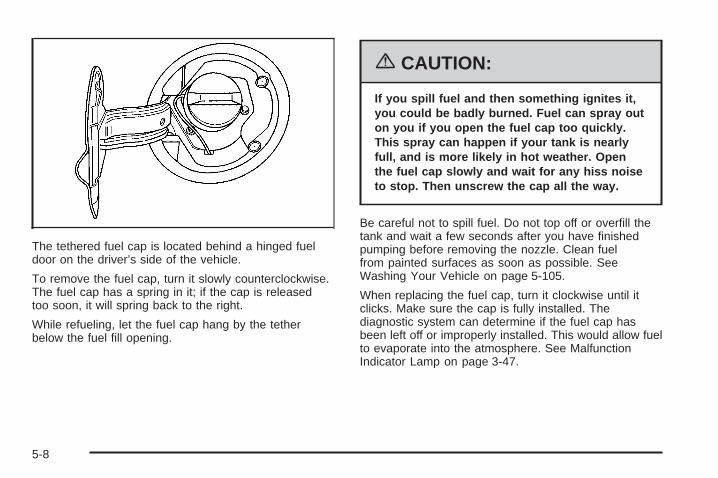
The tethered fuel cap is located behind a hinged fueldoor on the driver’s side of the vehicle.
To remove the fuel cap, turn it slowly counterclockwise.The fuel cap has a spring in it; if the cap is releasedtoo soon, it will spring back to the right.
While refueling, let the fuel cap hang by the tetherbelow the fuel fill opening.
{CAUTION:
If you spill fuel and then something ignites it,you could be badly burned. Fuel can spray outon you if you open the fuel cap too quickly.This spray can happen if your tank is nearlyfull, and is more likely in hot weather. Openthe fuel cap slowly and wait for any hiss noiseto stop. Then unscrew the cap all the way.
Be careful not to spill fuel. Do not top off or overfill thetank and wait a few seconds after you have finishedpumping before removing the nozzle. Clean fuelfrom painted surfaces as soon as possible. SeeWashing Your Vehicle on page 5-105.
When replacing the fuel cap, turn it clockwise until itclicks. Make sure the cap is fully installed. Thediagnostic system can determine if the fuel cap hasbeen left off or improperly installed. This would allow fuelto evaporate into the atmosphere. See MalfunctionIndicator Lamp on page 3-47.
5-8

The CHECK GAS CAP message will be displayed onthe Driver Information Center (DIC) if the fuel cap is notproperly installed. See DIC Warnings and Messageson page 3-72 for more information.
{CAUTION:
If a fire starts while you are refueling, do notremove the nozzle. Shut off the flow of fuel byshutting off the pump or by notifying thestation attendant. Leave the area immediately.
Notice: If you need a new fuel cap, be sure to getthe right type. Your dealer can get one for you.If you get the wrong type, it may not fit properly.This may cause your malfunction indicator lamp tolight and may damage your fuel tank and emissionssystem. See Malfunction Indicator Lamp onpage 3-47.
Filling a Portable Fuel Container
{CAUTION:
Never fill a portable fuel container while it is inyour vehicle. Static electricity discharge fromthe container can ignite the gasoline vapor.You can be badly burned and your vehicledamaged if this occurs. To help avoid injury toyou and others:
• Dispense gasoline only into approvedcontainers.
• Do not fill a container while it is inside avehicle, in a vehicle’s trunk, pickup bed, oron any surface other than the ground.
• Bring the fill nozzle in contact with theinside of the fill opening before operatingthe nozzle. Contact should be maintaineduntil the filling is complete.
• Do not smoke while pumping gasoline.
5-9
Checking Things Underthe Hood
{CAUTION:
An electric fan under the hood can start upand injure you even when the engine is notrunning. Keep hands, clothing and tools awayfrom any underhood electric fan.
{CAUTION:
Things that burn can get on hot engine partsand start a fire. These include liquids likefuel, oil, coolant, brake fluid, windshieldwasher and other fluids, and plastic orrubber. You or others could be burned. Becareful not to drop or spill things that willburn onto a hot engine.
5-10
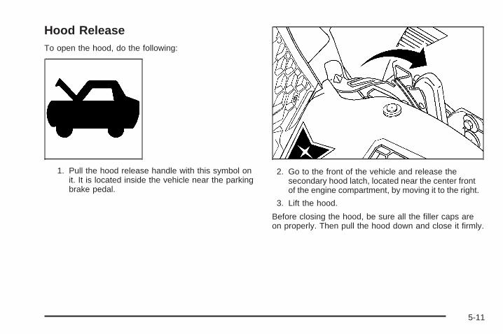
Hood ReleaseTo open the hood, do the following:
1. Pull the hood release handle with this symbol onit. It is located inside the vehicle near the parkingbrake pedal.
2. Go to the front of the vehicle and release thesecondary hood latch, located near the center frontof the engine compartment, by moving it to the right.
3. Lift the hood.
Before closing the hood, be sure all the filler caps areon properly. Then pull the hood down and close it firmly.
5-11
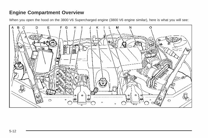
Engine Compartment OverviewWhen you open the hood on the 3800 V6 Supercharged engine (3800 V6 engine similar), here is what you will see:
5-12

A. Windshield Washer Fluid Reservoir. See “AddingWasher Fluid” under Windshield Washer Fluidon page 5-41.
B. Battery. See Battery on page 5-45.C. Remote Positive (+) Terminal. See Jump Starting on
page 5-46.D. Underhood Fuse Block. See Underhood Fuse Block
on page 5-114.E. Engine Coolant Recovery Tank. See Cooling System
on page 5-30.F. Pressure Cap. See Pressure Cap on page 5-28.G. Power Steering Fluid Reservoir (low in engine
compartment). See Power Steering Fluid onpage 5-40.
H. Supercharger Oil Fill Location (If Equipped). SeeSupercharger Oil on page 5-20.
I. Electric Cooling Fan. See Cooling System onpage 5-30.
J. Engine Oil Dipstick. See “Checking Engine Oil”under Engine Oil on page 5-16.
K. Engine Oil Fill Cap. See “When to Add Engine Oil”under Engine Oil on page 5-16.
L. Engine Coolant Bleed Valve. See “How to AddCoolant to the Radiator” under Cooling System onpage 5-30.
M. Automatic Transaxle Fluid Dipstick. See “Checkingthe Fluid Level” under Automatic Transaxle Fluidon page 5-23.
N. Brake Master Cylinder Reservoir. See “Brake Fluid”under Brakes on page 5-42.
O. Engine Air Cleaner/Filter. See Engine AirCleaner/Filter on page 5-21.
5-13
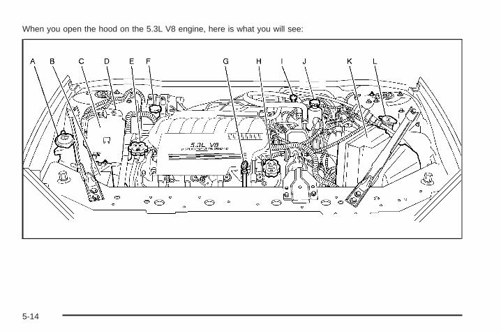
When you open the hood on the 5.3L V8 engine, here is what you will see:
5-14

A. Windshield Washer Fluid Reservoir. See “AddingWasher Fluid” under Windshield Washer Fluidon page 5-41.
B. Battery. See Battery on page 5-45.C. Underhood Fuse Block. See Underhood Fuse Block
on page 5-114.D. Remote Positive (+) Terminal. See Jump Starting on
page 5-46.E. Pressure Cap. See Pressure Cap on page 5-28.F. Power Steering Fluid Reservoir. See Power Steering
Fluid on page 5-40.G. Engine Oil Dipstick. See “Checking Engine Oil”
under Engine Oil on page 5-16.
H. Engine Oil Fill Cap. See “When to Add Engine Oil”under Engine Oil on page 5-16.
I. Automatic Transaxle Fluid Dipstick. See “Checkingthe Fluid Level” under Automatic Transaxle Fluidon page 5-23.
J. Brake Master Cylinder Reservoir. See “Brake Fluid”under Brakes on page 5-42.
K. Engine Air Cleaner/Filter. See Engine AirCleaner/Filter on page 5-21.
L. Engine Coolant Recovery Tank. See Cooling Systemon page 5-30.
5-15

Engine Oil
If this symbol, along withthe LOW OIL LEVELmessage appears on theDriver InformationCenter (DIC), it means youneed to check the engineoil level right away.
For more information, see LOW OIL LEVEL under DICWarnings and Messages on page 3-72.
You should check the engine oil level regularly; this isan added reminder.
Checking Engine OilIt is a good idea to check the engine oil every time youget fuel. In order to get an accurate reading, the oilmust be warm and the vehicle must be on level ground.
The engine oil dipstick handle is a yellow loop. SeeEngine Compartment Overview on page 5-12 forthe location of the engine oil dipstick.
1. Turn off the engine and give the oil several minutesto drain back into the oil pan. If you do not do this,the oil dipstick might not show the actual level.
2. Pull out the dipstick and clean it with a paper towelor cloth, then push it back in all the way. Remove itagain, keeping the tip down, and check the level.
5-16

When to Add Engine Oil
If the oil is below the cross-hatched area at the tip ofthe dipstick, you will need to add at least one quart/literof oil. But you must use the right kind. This sectionexplains what kind of oil to use. For engine oil crankcasecapacity, see Capacities and Specifications onpage 5-118.
Notice: Do not add too much oil. If the engine hasso much oil that the oil level gets above thecross-hatched area that shows the proper operatingrange, the engine could be damaged.
See Engine CompartmentOverview on page 5-12 forthe location of theengine oil fill cap.
Be sure to add enough oil to put the level somewherein the proper operating range in the cross-hatchedarea. Push the dipstick all the way back in when youare through.
V6 Engine
V8 Engine
5-17

What Kind of Engine Oil to Use
Look for two things:
• GM6094M
Your vehicle’s engine requires oil meeting GMStandard GM6094M. You should look for and useonly an oil that meets GM Standard GM6094M.
• SAE 5W-30
As shown in the viscosity chart, SAE 5W-30 is bestfor your vehicle.These numbers on an oil container show itsviscosity, or thickness. Do not use other viscosityoils such as SAE 20W-50.
Oils meeting theserequirements should alsohave the starburstsymbol on the container.This symbol indicatesthat the oil has beencertified by the AmericanPetroleum Institute (API).
You should look for this information on the oil container,and use only those oils that are identified as meetingGM Standard GM6094M and have the starburst symbolon the front of the oil container.
5-18

Notice: Use only engine oil identified as meetingGM Standard GM6094M and showing the AmericanPetroleum Institute Certified For Gasoline Enginesstarburst symbol. Failure to use the recommendedoil can result in engine damage not covered byyour warranty.
GM Goodwrench® oil meets all the requirements foryour vehicle.
If you are in an area of extreme cold, where thetemperature falls below −20°F (−29°C), it isrecommended that you use either an SAE 5W-30synthetic oil or an SAE 0W-30 oil. Both will provideeasier cold starting and better protection for the engineat extremely low temperatures.
Engine Oil AdditivesDo not add anything to your vehicle’s engine oil. Therecommended oils with the starburst symbol thatmeet GM Standard GM6094M are all you will need forgood performance and engine protection.
Engine Oil Life System
When to Change Engine OilYour vehicle has a computer system that lets you knowwhen to change the engine oil and filter. This is based onengine revolutions and engine temperature, and not onmileage. Based on driving conditions, the mileage atwhich an oil change will be indicated can varyconsiderably. For the oil life system to work properly, youmust reset the system every time the oil is changed.When the system has calculated that oil life has beendiminished, it will indicate that an oil change isnecessary. A CHANGE OIL SOON message will comeon. See DIC Warnings and Messages on page 3-72.Change the oil as soon as possible within the next600 miles (1 000 km). It is possible that, if youare driving under the best conditions, the oil life systemmay not indicate that an oil change is necessary forover a year. However, the engine oil and filter must bechanged at least once a year and at this time thesystem must be reset. Your dealer has GM-trainedservice people who will perform this work using genuineGM parts and reset the system. It is also important tocheck the oil regularly and keep it at the proper level.If the system is ever reset accidentally, you mustchange the oil at 3,000 miles (5 000 km) since the lastoil change. Remember to reset the oil life systemwhenever the oil is changed.
5-19
How to Reset the Engine OilLife SystemThe Engine Oil Life System calculates when to changethe engine oil and filter based on vehicle use. Anytimethe oil is changed, reset the system so it can calculatewhen the next oil change is required. If a situationoccurs where you change the oil prior to a CHANGEOIL SOON message appearing on the DIC, resetthe system.
To reset the oil life system, after the oil has beenchanged, use the following procedure:
1. Press the options button on the DIC until ENGINEOIL MONITOR appears on the DIC screen.
2. Press the set/reset button to reset the system.The next screen indicates that the engine oilmonitor system has been reset.If the vehicle is equipped with the trip computerDIC, when the gage button is pressed and the OILLIFE REMAINING mode appears, it should read100 percent OIL LIFE REMAINING.
3. Turn the key to OFF.
If the CHANGE OIL SOON message comes back onwhen you start your vehicle, the engine oil life systemhas not reset. Repeat the procedure.
What to Do with Used OilUsed engine oil contains certain elements that may beunhealthy for your skin and could even cause cancer.Do not let used oil stay on your skin for very long. Cleanyour skin and nails with soap and water, or a goodhand cleaner. Wash or properly dispose of clothing orrags containing used engine oil. See the manufacturer’swarnings about the use and disposal of oil products.
Used oil can be a threat to the environment. If youchange your own oil, be sure to drain all the oil from thefilter before disposal. Never dispose of oil by putting it inthe trash, pouring it on the ground, into sewers, or intostreams or bodies of water. Instead, recycle it by taking itto a place that collects used oil. If you have a problemproperly disposing of used oil, ask your dealer, a servicestation, or a local recycling center for help.
Supercharger OilBecause they are technically qualified and have theproper tools, you should have your dealer perform thismaintenance.
5-20

When to CheckSee Additional Required Services on page 6-6 for whenthe oil level should be checked.
What Kind of Oil to UseUse only the recommended supercharger oil. SeeRecommended Fluids and Lubricants on page 6-12.
Engine Air Cleaner/FilterThe engine air cleaner/filter is located in the enginecompartment on the driver’s side of the vehicle.See Engine Compartment Overview on page 5-12 formore information on location.
When to Inspect the Engine AirCleaner/FilterInspect the air cleaner/filter at the Maintenance IIintervals and replace it at the first oil change after each50,000 mile (83 000 km) interval. See ScheduledMaintenance on page 6-4 for more information. If youare driving in dusty/dirty conditions, inspect the filterat each engine oil change.
How to Inspect the Engine AirCleaner/FilterTo inspect the air cleaner/filter, remove the filter fromthe vehicle and lightly shake the filter to releaseloose dust and dirt. If the filter remains caked with dirt, anew filter is required.
To inspect or replace the engine air cleaner/filter do thefollowing:
3800 V6 Supercharged Engine shown, 3800 V6Engine similar
5-21

1. Lift the filter cover tabs on top of the engine aircleaner/filter housing.
2. Push the filter cover housing toward the engine.
3. Pull out the filter.
4. Inspect or replace the engine air cleaner/filter.
5. To reinstall the cover, position the tabs through theslots on the housing. If your vehicle has one of the3800 V6 engines, a notch on the sides of thefilter cover will indicate the correct engagement.
6. Push the cover tabs on top of the housing to lockthe cover in place.
{CAUTION:
Operating the engine with the air cleaner/filteroff can cause you or others to be burned. Theair cleaner not only cleans the air; it helps tostop flames if the engine backfires. If it isnot there and the engine backfires, you couldbe burned. Do not drive with it off, and becareful working on the engine with the aircleaner/filter off.
Notice: If the air cleaner/filter is off, a backfire cancause a damaging engine fire. And, dirt caneasily get into your engine, which will damage it.Always have the air cleaner/filter in place when youare driving.
5.3L V8 Engine
5-22
Automatic Transaxle Fluid
When to Check and Change AutomaticTransaxle FluidA good time to check the automatic transaxle fluid levelis when the engine oil is changed.
Change the fluid and filter at the intervals listed inAdditional Required Services on page 6-6, and be sureto use the transaxle fluid listed in RecommendedFluids and Lubricants on page 6-12.
How to Check AutomaticTransaxle FluidBecause this operation can be a little difficult, youmay choose to have this done at the dealershipservice department.
If you do it yourself, be sure to follow all the instructionshere, or you could get a false reading on the dipstick.
Notice: Too much or too little fluid can damage thetransaxle. Too much can mean that some of the fluidcould come out and fall on hot engine or exhaustsystem parts, starting a fire. Too little fluid couldcause the transaxle to overheat. Be sure to get anaccurate reading if you check the transaxle fluid.
Wait at least 30 minutes before checking the transaxlefluid level if you have been driving:
• When outside temperatures are above 90°F (32°C).
• At high speed for quite a while.
• In heavy traffic — especially in hot weather.
• While pulling a trailer.
To get the right reading, the fluid should be atnormal operating temperature, which is 180°F to200°F (82°C to 93°C).
Get the vehicle warmed up by driving about15 miles (24 km) when outside temperatures areabove 50°F (10°C). If it is colder than 50°F (10°C),you may have to drive longer.
5-23

Checking the Fluid LevelPrepare the vehicle as follows:
1. Park the vehicle on a level place. Keep the enginerunning.
2. With the parking brake applied, place the shift leverin PARK (P).
3. With your foot on the brake pedal, move theshift lever through each gear, pausing for aboutthree seconds in each one. Then, position the shiftlever in PARK (P).
4. Let the engine run at idle for three to five minutes.
Then, without shutting off the engine, followthese steps:
The transaxle fluid dipstickhandle has this symbol onit, and is located nearthe rear of the enginecompartment. See EngineCompartment Overviewon page 5-12 for moreinformation on location.
1. Pull out the dipstick and wipe it with a clean rag orpaper towel.
2. Push it back in all the way, wait three seconds andthen pull it back out again.
3. Check both sides of the dipstick, and read thelower level. The fluid level must be in thecrosshatched area.
4. If the fluid level is in the acceptable range, push thedipstick back in all the way.
5-24
How to Add Automatic Transaxle FluidRefer to the Maintenance Schedule to determinewhat kind of transaxle fluid to use. See RecommendedFluids and Lubricants on page 6-12.
If the fluid level is low, add only enough of the properfluid to bring the level into the crosshatched area onthe dipstick.
1. Pull out the dipstick.
2. Using a long-neck funnel, add enough fluid at thedipstick hole to bring it to the proper level.It does not take much fluid, generally less thanone pint (0.5 L). Do not overfill.
Notice: Use of the incorrect automatic transaxlefluid may damage your vehicle, and the damagesmay not be covered by your warranty. Alwaysuse the automatic transaxle fluid listed inRecommended Fluids and Lubricants on page 6-12.
3. After adding fluid, recheck the fluid level asdescribed under “How to Check AutomaticTransaxle Fluid,” earlier in this section.
4. When the correct fluid level is obtained, push thedipstick back in all the way.
Engine CoolantThe cooling system in the vehicle is filled withDEX-COOL® engine coolant. This coolant is designedto remain in the vehicle for five years or 150,000 miles(240 000 km), whichever occurs first, if onlyDEX-COOL® extended life coolant is added.The following explains the cooling system and how toadd coolant when it is low. If there is a problemwith engine overheating or if coolant needs to be addedto the radiator, see Engine Overheating on page 5-28.A 50/50 mixture of clean, drinkable water andDEX-COOL® engine coolant will:• Give freezing protection down to −34°F (−37°C).• Give boiling protection up to 265°F (129°C).• Protect against rust and corrosion.• Help keep the proper engine temperature.• Let the warning lights and gages work as
they should.
Notice: Using coolant other than DEX-COOL ® maycause premature engine, heater core, or radiatorcorrosion. In addition, the engine coolant mayrequire changing sooner, at the first maintenanceservice after each 25,000 miles (41 500 km) or24 months, whichever occurs first. Any repairswould not be covered by your warranty. Always useDEX-COOL® (silicate-free) coolant in your vehicle.
5-25

What to UseUse a mixture of one-half clean, drinkable water andone-half DEX-COOL® engine coolant which willnot damage aluminum parts. If this coolant mixture isused, nothing else needs to be added.
{CAUTION:
Adding only plain water to your coolingsystem can be dangerous. Plain water, orsome other liquid such as alcohol, can boilbefore the proper coolant mixture will. Yourvehicle’s coolant warning system is set for theproper coolant mixture. With plain water or thewrong mixture, your engine could get too hotbut you would not get the overheat warning.Your engine could catch fire and you or otherscould be burned. Use a 50/50 mixture of clean,drinkable water and DEX-COOL ® coolant.
Notice: If you use an improper coolant mixture,your engine could overheat and be badly damaged.The repair cost would not be covered by yourwarranty. Too much water in the mixture can freezeand crack the engine, radiator, heater core andother parts.
If coolant needs to be added more than four times ayear, have your dealer check the cooling system.
Notice: If you use extra inhibitors and/or additivesin your vehicle’s cooling system, you coulddamage your vehicle. Use only the proper mixtureof the engine coolant listed in this manual forthe cooling system. See Recommended Fluids andLubricants on page 6-12 for more information.
5-26
Checking Coolant
The coolant recovery tankcap has this symbol on it.
See Engine Compartment Overview on page 5-12for more information on the location of the coolantrecovery tank.
The vehicle must be on a level surface when checkingthe coolant level.
When the engine is cold, the coolant level should be atthe cold fill line or a little higher. The cold fill line ismarked with the same symbol as the coolant recoverytank cap.
Adding CoolantIf more coolant is needed, add the proper DEX-COOL®
coolant mixture at the coolant recovery tank, but becareful not to spill it.
If the coolant recovery tank is completely empty, addcoolant to the radiator. See Engine Overheatingon page 5-28.
{CAUTION:
Turning the pressure cap when the engine andradiator are hot can allow steam and scaldingliquids to blow out and burn you badly. With thecoolant recovery tank, you will almost neverhave to add coolant at the radiator. Never turnthe pressure cap — even a little — when theengine and radiator are hot.
{CAUTION:
You can be burned if you spill coolant on hotengine parts. Coolant contains ethylene glycol,and it will burn if the engine parts are hotenough. Do not spill coolant on a hot engine.
Occasionally check the coolant level in the radiator. Forinformation on how to add coolant to the radiator,see Cooling System on page 5-30.
5-27

Pressure CapNotice: If the pressure cap is not tightly installed,coolant loss and possible engine damage may occur.Be sure the cap is properly and tightly secured.
See Engine Compartment Overview on page 5-12 formore information on location.
Engine OverheatingThere is a coolant temperature gage and a warning lighton the instrument panel that indicate an overheatedengine condition. See Engine Coolant TemperatureGage on page 3-46 and Engine Coolant TemperatureWarning Light on page 3-46.
If Steam Is Coming From Your Engine
{CAUTION:
Steam from an overheated engine can burnyou badly, even if you just open the hood. Stayaway from the engine if you see or hear steamcoming from it. Just turn it off and geteveryone away from the vehicle until it coolsdown. Wait until there is no sign of steam orcoolant before you open the hood.
If you keep driving when your engine isoverheated, the liquids in it can catch fire. Youor others could be badly burned. Stop yourengine if it overheats, and get out of thevehicle until the engine is cool.
See Overheated Engine Protection OperatingMode on page 5-30 for information on drivingto a safe place in an emergency.
5-28

Notice: If your engine catches fire because youkeep driving with no coolant, your vehicle canbe badly damaged. The costly repairs would not becovered by your warranty. See Overheated EngineProtection Operating Mode on page 5-30 forinformation on driving to a safe place in anemergency.
If No Steam is Coming From YourEngineAn overheat warning can indicate a serious problem.
If you get an engine overheat warning but see orhear no steam, the problem may not be too serious.Sometimes the engine can get a little too hot when you:
• Climb a long hill on a hot day.
• Stop after high-speed driving.
• Idle for long periods in traffic.
• Tow a trailer.
If an overheat warning occurs without any sign ofsteam, try this for a minute or so:
1. In heavy traffic, let the engine idle in NEUTRAL (N)while stopped. If it is safe to do so, pull off the road,shift to PARK (P) or NEUTRAL (N) and let theengine idle.
2. Set the heater at the highest setting and the fan atthe highest speed and open the windows asnecessary.
If the overheat warning no longer exists, the vehicle canbe driven. Just to be safe, drive slower for about10 minutes. If the warning does not come back on, thevehicle can be driven normally.
If the warning continues, and you have not stopped, pullover, stop, and park the vehicle right away.
If there is still no sign of steam, idle the engine forthree minutes while parked. If the warning is still there,turn off the engine and get everyone out of thevehicle until it cools down. Also, see “OverheatedEngine Protection Operating Mode” later in this section.
You may decide not to lift the hood but to get servicehelp right away.
5-29

Overheated Engine ProtectionOperating ModeThe overheated engine protection operating modeallows the vehicle to be driven to a safe place in anemergency situation. If an overheated engine conditionexists, this protection mode alternates firing groupsof cylinders to help prevent engine damage. Inthis mode, there will be a significant loss in power andengine performance. The engine coolant temperaturegage indicator will move to the shaded area, andthe engine coolant temperature warning light will comeon, showing that an overheated engine conditionexists. Driving extended miles (km) and/or towing atrailer in the overheated engine protection mode shouldbe avoided.
Notice: After driving in the overheated engineprotection operating mode, to avoid engine damage,allow the engine to cool before attempting anyrepair. The engine oil will be severely degraded.Repair the cause of coolant loss, change the oil andreset the oil life system. See Engine Oil onpage 5-16.
Cooling SystemWhen you decide it is safe to lift the hood, here is whatyou will see:
A. Coolant Recovery TankB. Electric Engine Cooling Fan(s)C. Pressure Cap
3800 V6 Supercharged Engine shown, 3800 V6Engine similar
5-30
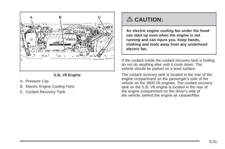
A. Pressure CapB. Electric Engine Cooling FansC. Coolant Recovery Tank
{CAUTION:
An electric engine cooling fan under the hoodcan start up even when the engine is notrunning and can injure you. Keep hands,clothing and tools away from any underhoodelectric fan.
If the coolant inside the coolant recovery tank is boiling,do not do anything else until it cools down. Thevehicle should be parked on a level surface.
The coolant recovery tank is located in the rear of theengine compartment on the passenger’s side of thevehicle on the 3800 V6 engines. The coolant recoverytank on the 5.3L V8 engine is located in the rear ofthe engine compartment on the driver’s side ofthe vehicle, behind the engine air cleaner/filter.
5.3L V8 Engine
5-31

When the engine is cold, the coolant level should be ator above the cold fill line on the coolant recoverytank. To check the coolant level, look for the cold fill lineon the side of the coolant recovery tank that faces theengine. If the level is not correct, there may be a leak atthe pressure cap or in the radiator hoses, heaterhoses, radiator, water pump, or somewhere else in thecooling system.
{CAUTION:
Heater and radiator hoses, and other engineparts, can be very hot. Do not touch them. Ifyou do, you can be burned.
Do not run the engine if there is a leak. If yourun the engine, it could lose all coolant. Thatcould cause an engine fire, and you could beburned. Get any leak fixed before you drivethe vehicle.
If there seems to be no leak, with the engine on, checkto see if the electric engine cooling fan(s) are running.If the engine is overheating, the fan(s) should berunning. If the fan(s) are not running, the vehicleneeds service.
Notice: Engine damage from running your enginewithout coolant is not covered by your warranty. SeeOverheated Engine Protection Operating Mode onpage 5-30 for information on driving to a safe placein an emergency.
Notice: Using coolant other than DEX-COOL ® maycause premature engine, heater core or radiatorcorrosion. In addition, the engine coolant mayrequire changing sooner, at 30,000 miles (50 000 km)or 24 months, whichever occurs first. Any repairswould not be covered by your warranty. Always useDEX-COOL® (silicate-free) coolant in your vehicle.
5-32

How to Add Coolant to the CoolantRecovery Tank
{CAUTION:
Adding only plain water to your coolingsystem can be dangerous. Plain water, orsome other liquid such as alcohol, can boilbefore the proper coolant mixture will. Yourvehicle’s coolant warning system is set for theproper coolant mixture. With plain water or thewrong mixture, your engine could get too hotbut you would not get the overheat warning.Your engine could catch fire and you or otherscould be burned. Use a 50/50 mixture of clean,drinkable water and DEX-COOL ® coolant.
If you have not found a problem yet, but the coolantlevel is not at the cold fill line, add a 50/50 mixtureof clean, drinkable water and DEX-COOL® enginecoolant at the coolant recovery tank. See EngineCoolant on page 5-25 for more information.
Notice: In cold weather, water can freeze and crackthe engine, radiator, heater core and other parts.Use the recommended coolant and the propercoolant mixture.
{CAUTION:
You can be burned if you spill coolant on hotengine parts. Coolant contains ethylene glycoland it will burn if the engine parts are hotenough. Do not spill coolant on a hot engine.
When the coolant level in the coolant recovery tank is atthe cold fill line, start the vehicle.
5-33

If the overheat warning continues, there is one morething you can try. You can add the proper coolantmixture directly to the radiator, but be sure the systemis cool before you do it.
{CAUTION:
Steam and scalding liquids from a hot coolingsystem can blow out and burn you badly. Theyare under pressure, and if you turn thepressure cap — even a little — they can comeout at high speed. Never turn the cap when thecooling system, including the pressure cap, ishot. Wait for the cooling system and pressurecap to cool if you ever have to turn thepressure cap.
How to Add Coolant to the Radiator(3800 V6 Engines)
Notice: Your engine has a specific radiator fillprocedure. Failure to follow this procedure couldcause your engine to overheat and be severelydamaged.
1. You can remove the pressure cap when the coolingsystem, including the pressure cap and upperradiator hose, is no longer hot. Turn the cap slowlycounterclockwise.If you hear a hiss, wait for that to stop. A hissmeans there is still some pressure left.
2. Then keep turning the pressure cap and remove it.
3800 V6 Supercharged Engine shown, 3800 V6Engine similar
5-34

{CAUTION:
You can be burned if you spill coolant on hotengine parts. Coolant contains ethylene glycoland it will burn if the engine parts are hotenough. Do not spill coolant on a hot engine.
3. Remove the Series III V6 engine cover shield toaccess the bleed valve.
3.1. Clean the area around the engine oil fill tubeand cap before removing. Twist the oil filltube, with cap attached, counterclockwiseand remove it.
3800 V6 Engine
5-35
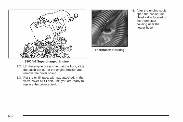
3.2. Lift the engine cover shield at the front, slidethe catch tab out of the engine bracket andremove the cover shield.
3.3. Put the oil fill tube, with cap attached, in thevalve cover oil fill hole until you are ready toreplace the cover shield.
4. After the engine cools,open the coolant airbleed valve located onthe thermostathousing near theheater hose.
3800 V6 Supercharged Engine
Thermostat Housing
5-36
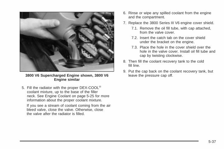
5. Fill the radiator with the proper DEX-COOL®
coolant mixture, up to the base of the fillerneck. See Engine Coolant on page 5-25 for moreinformation about the proper coolant mixture.If you see a stream of coolant coming from the airbleed valve, close the valve. Otherwise, closethe valve after the radiator is filled.
6. Rinse or wipe any spilled coolant from the engineand the compartment.
7. Replace the 3800 Series III V6 engine cover shield.7.1. Remove the oil fill tube, with cap attached,
from the valve cover.7.2. Insert the catch tab on the cover shield
under the bracket on the engine.7.3. Place the hole in the cover shield over the
hole in the valve cover. Install oil fill tube andcap by twisting clockwise.
8. Then fill the coolant recovery tank to the coldfill line.
9. Put the cap back on the coolant recovery tank, butleave the pressure cap off.3800 V6 Supercharged Engine shown, 3800 V6
Engine similar
5-37

10. Start the engine and let it run until you can feel theupper radiator hose getting hot. Watch out for theengine cooling fan(s).
11. By this time, the coolant level inside the radiatorfiller neck may be lower. If the level is lower, addmore of the proper DEX-COOL® coolant mixturethrough the filler neck until the level reachesthe base of the filler neck.
12. Then replace the pressure cap. At any time duringthis procedure if coolant begins to flow out of thefiller neck, reinstall the pressure cap. Be surethe pressure cap is hand-tight and fully seated.
13. Check the coolant in the recovery tank. The level inthe coolant recovery tank should be at the cold fillline when the engine is cold.
3800 V6 Supercharged Engine shown, 3800 V6Engine similar
5-38

How to Add Coolant to the CoolingSystem (5.3L V8 Engine)
Notice: Your engine has a specific cooling systemdrain and fill procedure. Failure to follow thisprocedure could cause your engine to overheatand be severely damaged. If your engine’s coolingsystem needs to be drained and re-filled, please seeyour dealer.
You can remove thepressure cap when thecooling system, includingthe pressure cap andupper radiator hose is nolonger hot. Turn thepressure cap slowlycounterclockwise.
1. If you hear a hiss, wait for that to stop. A hissmeans that there is still some pressure left.
2. Then keep turning the pressure cap to remove thepressure cap.
{CAUTION:
You can be burned if you spill coolant on hotengine parts. Coolant contains ethylene glycoland it will burn if the engine parts are hotenough. Do not spill coolant on a hot engine.
3. Fill the cooling system with the proper DEX-COOL®
coolant mixture, up to the base of the filler neck.See Engine Coolant on page 5-25 for moreinformation about the proper coolant mixture.
4. Rinse or wipe any spilled coolant from the engineand the compartment.
5. Then fill the coolant recovery tank to the coldfill line.
6. Install the coolant recovery tank cap and thepressure cap.
7. If the coolant in the recovery tank is constantly low,you should have a dealership service departmentinspect your vehicle for leaks.
5-39

Power Steering Fluid
See Engine CompartmentOverview on page 5-12 forreservoir location.
When to Check Power Steering FluidIt is not necessary to regularly check power steeringfluid unless a leak is suspected in the system, oran unusual noise is heard. A fluid loss in this systemcould indicate a problem. Have the system inspectedand repaired.
How to Check Power Steering FluidTo check the power steering fluid, do the following:
1. Turn the key off and let the engine compartmentcool down.
2. Wipe the cap and the top of the reservoir clean.
3. Unscrew the cap and wipe the dipstick with aclean rag.
4. Replace the cap and completely tighten it.
5. Remove the cap again and look at the fluid level onthe dipstick
The fluid level should be between the ADD and HOTmarks when the engine is cold.
When the engine compartment is hot, the level shouldbe at the HOT mark.
If the fluid is at the ADD mark when the engine is coldor hot, power steering fluid should be added.
What to UseTo determine what kind of fluid to use, seeRecommended Fluids and Lubricants on page 6-12.Always use the proper fluid. Failure to use the properfluid can cause leaks and damage hoses and seals.
5-40
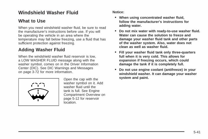
Windshield Washer Fluid
What to UseWhen you need windshield washer fluid, be sure to readthe manufacturer’s instructions before use. If you willbe operating the vehicle in an area where thetemperature may fall below freezing, use a fluid that hassufficient protection against freezing.
Adding Washer FluidWhen the windshield washer fluid reservoir is low,a LOW WASHER FLUID message along with thewasher symbol, comes on in the Driver InformationCenter (DIC). See DIC Warnings and Messageson page 3-72 for more information.
Open the cap with thewasher symbol on it. Addwasher fluid until thetank is full. See EngineCompartment Overview onpage 5-12 for reservoirlocation.
Notice:
• When using concentrated washer fluid,follow the manufacturer’s instructions foradding water.
• Do not mix water with ready-to-use washer fluid.Water can cause the solution to freeze anddamage your washer fluid tank and other partsof the washer system. Also, water does notclean as well as washer fluid.
• Fill your washer fluid tank only three-quartersfull when it is very cold. This allows forexpansion if freezing occurs, which coulddamage the tank if it is completely full.
• Do not use engine coolant (antifreeze) in yourwindshield washer. It can damage your washersystem and paint.
5-41

Brakes
Brake Fluid
Your brake master cylinderreservoir is filled withDOT-3 brake fluid. SeeEngine CompartmentOverview on page 5-12 forthe location of thereservoir.
There are only two reasons why the brake fluid level inthe reservoir might go down. The first is that thebrake fluid goes down to an acceptable level duringnormal brake lining wear. When new linings are put in,the fluid level goes back up. The other reason isthat fluid is leaking out of the brake system. If it is, youshould have your brake system fixed, since a leakmeans that sooner or later your brakes will not workwell, or will not work at all.
So, it is not a good idea to top off your brake fluid.Adding brake fluid will not correct a leak. If you add fluidwhen your linings are worn, then you will have toomuch fluid when you get new brake linings. You shouldadd or remove brake fluid, as necessary, only whenwork is done on the brake hydraulic system.
{CAUTION:
If you have too much brake fluid, it can spill onthe engine. The fluid will burn if the engine ishot enough. You or others could be burned,and your vehicle could be damaged. Add brakefluid only when work is done on the brakehydraulic system.
When your brake fluid falls to a low level, your brakewarning light will come on. See Brake System WarningLight on page 3-42.
5-42
What to AddWhen you do need brake fluid, use only DOT-3 brakefluid. Use new brake fluid from a sealed containeronly. See Recommended Fluids and Lubricants onpage 6-12.
Always clean the brake fluid reservoir cap and the areaaround the cap before removing it. This will helpkeep dirt from entering the reservoir.
{CAUTION:
With the wrong kind of fluid in your brakesystem, your brakes may not work well, or theymay not even work at all. This could cause acrash. Always use the proper brake fluid.
Notice:
• Using the wrong fluid can badly damage brakesystem parts. For example, just a few drops ofmineral-based oil, such as engine oil, in yourbrake system can damage brake system parts sobadly that they will have to be replaced. Do notlet someone put in the wrong kind of fluid.
• If you spill brake fluid on your vehicle’s paintedsurfaces, the paint finish can be damaged. Becareful not to spill brake fluid on your vehicle. Ifyou do, wash it off immediately. See WashingYour Vehicle on page 5-105.
5-43

Brake WearYour vehicle has four-wheel disc brakes.
Disc brake pads have built-in wear indicators that makea high-pitched warning sound when the brake padsare worn and new pads are needed. The soundmay come and go or be heard all the time your vehicleis moving, except when you are pushing on thebrake pedal firmly.
{CAUTION:
The brake wear warning sound meansthat soon your brakes will not work well.That could lead to an accident. When you hearthe brake wear warning sound, have yourvehicle serviced.
Notice: Continuing to drive with worn-out brakepads could result in costly brake repair.
Some driving conditions or climates may cause abrake squeal when the brakes are first applied or lightlyapplied. This does not mean something is wrong withyour brakes.
Properly torqued wheel nuts are necessary to helpprevent brake pulsation. When tires are rotated, inspectbrake pads for wear and evenly tighten wheel nuts inthe proper sequence to GM torque specifications.
Brake linings should always be replaced as completeaxle sets.
Brake Pedal TravelSee your dealer if the brake pedal does not return tonormal height, or if there is a rapid increase inpedal travel. This could be a sign of brake trouble.
Brake AdjustmentEvery time you apply the brakes, with or without thevehicle moving, your brakes adjust for wear.
5-44

Replacing Brake System PartsThe braking system on a vehicle is complex. Its manyparts have to be of top quality and work well together ifthe vehicle is to have really good braking. Yourvehicle was designed and tested with top-qualityGM brake parts. When you replace parts of your brakingsystem — for example, when your brake linings weardown and you need new ones put in — be sure you getnew approved GM replacement parts. If you do not,your brakes may no longer work properly. For example,if someone puts in brake linings that are wrong foryour vehicle, the balance between your front and rearbrakes can change — for the worse. The brakingperformance you have come to expect can change inmany other ways if someone puts in the wrongreplacement brake parts.
BatteryYour vehicle has a maintenance free battery. When it istime for a new battery, get one that has the replacementnumber shown on the original battery’s label. Werecommend an ACDelco® replacement battery. SeeEngine Compartment Overview on page 5-12 forbattery location.
Warning: Battery posts, terminals, and relatedaccessories contain lead and lead compounds,chemicals known to the State of California tocause cancer and reproductive harm. Wash handsafter handling.
If the battery has a very low charge or is dead, you maynot be able to remove the ignition key from the ignitionswitch or shift out of PARK (P). Refer to ShiftingOut of Park (P) on page 2-32.
Vehicle StorageIf you are not going to drive your vehicle for 25 daysor more, remove the black, negative (−) cable fromthe battery. This will help keep the battery fromrunning down.
{CAUTION:
Batteries have acid that can burn you and gasthat can explode. You can be badly hurt if youare not careful. See Jump Starting onpage 5-46 for tips on working around a batterywithout getting hurt.
5-45

Jump StartingIf your vehicle’s battery has run down, you may want touse another vehicle and some jumper cables to startyour vehicle. Be sure to use the following steps to doit safely.
{CAUTION:
Batteries can hurt you. They can be dangerousbecause:
• They contain acid that can burn you.• They contain gas that can explode
or ignite.• They contain enough electricity to
burn you.
If you do not follow these steps exactly, someor all of these things can hurt you.
Notice: Ignoring these steps could result in costlydamage to your vehicle that would not be coveredby your warranty.
Trying to start your vehicle by pushing or pulling itwill not work, and it could damage your vehicle.
1. Check the other vehicle. It must have a 12-voltbattery with a negative ground system.
Notice: If the other vehicle’s system is not a 12-voltsystem with a negative ground, both vehicles canbe damaged. Only use vehicles with 12-volt systemswith negative grounds to jump start your vehicle.
2. Get the vehicles close enough so the jumper cablescan reach, but be sure the vehicles are not touchingeach other. If they are, it could cause a groundconnection you do not want. You would not be ableto start your vehicle, and the bad groundingcould damage the electrical systems.To avoid the possibility of the vehicles rolling, setthe parking brake firmly on both vehicles involved inthe jump start procedure. Put an automatictransaxle in PARK (P) or a manual transaxle inNEUTRAL before setting the parking brake.
5-46
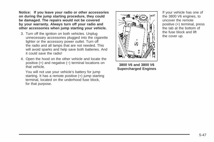
Notice: If you leave your radio or other accessorieson during the jump starting procedure, they couldbe damaged. The repairs would not be coveredby your warranty. Always turn off your radio andother accessories when jump starting your vehicle.
3. Turn off the ignition on both vehicles. Unplugunnecessary accessories plugged into the cigarettelighter or the accessory power outlet. Turn offthe radio and all lamps that are not needed. Thiswill avoid sparks and help save both batteries. Andit could save the radio!
4. Open the hood on the other vehicle and locate thepositive (+) and negative (−) terminal locations onthat vehicle.You will not use your vehicle’s battery for jumpstarting. It has a remote positive (+) jump startingterminal, located on the underhood fuse block,for that purpose.
If your vehicle has one ofthe 3800 V6 engines, touncover the remotepositive (+) terminal, pressthe tab at the bottom ofthe fuse block and liftthe cover up.
3800 V6 and 3800 V6Supercharged Engines
5-47

If your vehicle has the5.3L V8 engine, to uncoverthe remote positive (+)terminal, remove the fuseblock cover.
Always use the remote positive (+) terminal insteadof the positive (+) terminal on the battery. SeeEngine Compartment Overview on page 5-12 formore information on location.
{CAUTION:
An electric fan can start up even when theengine is not running and can injure you. Keephands, clothing and tools away from anyunderhood electric fan.
{CAUTION:
Fans or other moving engine parts can injureyou badly. Keep your hands away from movingparts once the engine is running.
{CAUTION:
Using a match near a battery can cause batterygas to explode. People have been hurt doingthis, and some have been blinded. Use aflashlight if you need more light.Be sure the battery has enough water. You donot need to add water to the battery installedin your new vehicle. But if a battery has fillercaps, be sure the right amount of fluid is there.If it is low, add water to take care of that first.If you do not, explosive gas could be present.Battery fluid contains acid that can burn you.Do not get it on you. If you accidentally get itin your eyes or on your skin, flush the placewith water and get medical help immediately.
5.3L V8 Engine
5-48

5. Check that the jumper cables do not have loose ormissing insulation. If they do, you could get ashock. The vehicles could be damaged too.Before you connect the cables, here are somebasic things you should know. Positive (+) will go topositive (+) or to a remote positive (+) terminal ifthe vehicle has one. Negative will go to a heavy,unpainted metal engine part or to a remotenegative (−) terminal if the vehicle has one.Do not connect positive (+) to negative (−), or youwill get a short that would damage the batteryand maybe other parts too. And do not connect thenegative (−) cable to the negative (−) terminal onthe dead battery because this can cause sparks.
6. Connect the red positive (+) cable to the positive (+)terminal location on the vehicle with the deadbattery. Use a remote positive (+) terminal if thevehicle has one.
7. Do not let the other end touch metal. Connect it tothe positive (+) terminal location on the vehicle withthe good battery. Use a remote positive (+)terminal if the vehicle has one.
8. Now connect the black negative (−) cable to thenegative (−) terminal location on the vehicle withthe good battery. Use a remote negative (−) terminalif the vehicle has one.Do not let the other end touch anything until thenext step. The other end of the negative (−) cabledoes not go to the dead battery. It goes to aheavy, unpainted metal engine part or to a remotenegative (–) terminal on the vehicle with thedead battery.
9. Connect the other end of the negative (−) cable atleast 18 inches (45 cm) away from the dead battery,but not near engine parts that move. The electricalconnection is just as good there, and the chanceof sparks getting back to the battery is much less.
10. Now start the vehicle with the good battery and runthe engine for a while.
11. Try to start the vehicle that had the dead battery.If it will not start after a few tries, it probablyneeds service.
5-49

Notice: If the jumper cables are connected orremoved in the wrong order, electrical shorting mayoccur and damage the vehicle. The repairs wouldnot be covered by your warranty. Always connectand remove the jumper cables in the correctorder, making sure that the cables do not toucheach other or other metal.
A. Heavy, Unpainted Metal Engine Part or RemoteNegative (−) Terminal
B. Good Battery or Remote Positive (+) and RemoteNegative (−) Terminals
C. Dead Battery or Remote Positive (+) Terminal
To disconnect the jumper cables from both vehicles, dothe following:
1. Disconnect the black negative (−) cable from thevehicle that had the dead battery.
2. Disconnect the black negative (−) cable from thevehicle with the good battery.
3. Disconnect the red positive (+) cable from thevehicle with the good battery.
4. Disconnect the red positive (+) cable from theother vehicle.
5. Return the remote positive (+) terminal cover to itsoriginal position.
Headlamp AimingThe vehicle has a visual optical headlamp aimingsystem. The aim has been preset at the factory andshould need no further adjustment.
However, If the vehicle is damaged in an accident, theheadlamp aim may be affected and adjustment maybe necessary.
If oncoming vehicles flash their high beams at you, thismay also mean the vertical aim needs to be adjusted.
Jumper Cable Removal
5-50
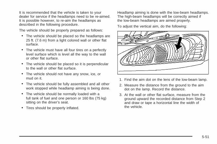
It is recommended that the vehicle is taken to yourdealer for service if the headlamps need to be re-aimed.It is possible however, to re-aim the headlamps asdescribed in the following procedure.
The vehicle should be properly prepared as follows:
• The vehicle should be placed so the headlamps are25 ft. (7.6 m) from a light colored wall or other flatsurface.
• The vehicle must have all four tires on a perfectlylevel surface which is level all the way to the wallor other flat surface.
• The vehicle should be placed so it is perpendicularto the wall or other flat surface.
• The vehicle should not have any snow, ice, ormud on it.
• The vehicle should be fully assembled and all otherwork stopped while headlamp aiming is being done.
• The vehicle should be normally loaded with afull tank of fuel and one person or 160 lbs (75 kg)sitting on the driver’s seat.
• Tires should be properly inflated.
Headlamp aiming is done with the low-beam headlamps.The high-beam headlamps will be correctly aimed ifthe low-beam headlamps are aimed properly.
To adjust the vertical aim, do the following:
1. Find the aim dot on the lens of the low-beam lamp.
2. Measure the distance from the ground to the aimdot on the lamp. Record the distance.
3. At the wall or other flat surface, measure from theground upward the recorded distance from Step 2and draw or tape a horizontal line the width ofthe vehicle.
5-51
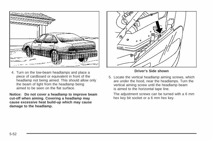
4. Turn on the low-beam headlamps and place apiece of cardboard or equivalent in front of theheadlamp not being aimed. This should allow onlythe beam of light from the headlamp beingaimed to be seen on the flat surface.
Notice: Do not cover a headlamp to improve beamcut-off when aiming. Covering a headlamp maycause excessive heat build-up which may causedamage to the headlamp.
5. Locate the vertical headlamp aiming screws, whichare under the hood, near the headlamps. Turn thevertical aiming screw until the headlamp beamis aimed to the horizontal tape line.The adjustment screws can be turned with a 6 mmhex key bit socket or a 6 mm hex key.
Driver’s Side shown
5-52
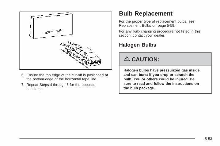
6. Ensure the top edge of the cut-off is positioned atthe bottom edge of the horizontal tape line.
7. Repeat Steps 4 through 6 for the oppositeheadlamp.
Bulb ReplacementFor the proper type of replacement bulbs, seeReplacement Bulbs on page 5-59.
For any bulb changing procedure not listed in thissection, contact your dealer.
Halogen Bulbs
{CAUTION:
Halogen bulbs have pressurized gas insideand can burst if you drop or scratch thebulb. You or others could be injured. Besure to read and follow the instructions onthe bulb package.
5-53

Headlamps and Sidemarker LampsTo replace a headlamp or sidemarker bulb, do thefollowing:
1. Open the hood. See Hood Release on page 5-11for more information.
A. High-Beam HeadlampB. Low-Beam HeadlampC. Sidemarker Lamp
2. Locate the metal retaining clip. Remove the bolt.
3. Pull up half-way on the metal retaining clipwhile pushing rearward on the headlamp.Align the square cut-out on the retaining clip withthe notch on the headlamp.
5-54

4. Pull the headlamp assembly straight out from thevehicle. (Moving the headlamp up and downslightly may help with its removal.)
A. High-Beam HeadlampB. Low-Beam HeadlampC. Sidemarker Lamp
5. Turn the bulb socket ring one-quarter of a turncounterclockwise to remove it from the headlampassembly.
6. Pull the old bulb from the socket.
7. Place the new bulb into the socket.
8. Turn the bulb socket ring one-quarter turn clockwiseto reinstall it back into the headlamp assembly.
5-55

9. Carefully reinstall the headlamp assembly.
10. Push down on the metal retaining clip while pushingrearward on the headlamp, making sure theheadlamp assembly is secure.
11. Reinstall the bolt and tighten to secure.
Front Turn Signal, Parking andFog LampsThe front turn signal, parking, and fog lamps (ifequipped) are located below the headlamp assembly.
A. Front Turn Signal/Parking LampB. Fog Lamp (If Equipped)
To replace one of these bulbs, do the following:
1. Follow Steps 1 through 4 of the headlampreplacement procedure. See Headlamps andSidemarker Lamps on page 5-54 for moreinformation.
2. Locate the front turnsignal/parking lamp (allmodels) and foglamp bulbs (ifequipped), which arelocated below theheadlamp assembly.
The arrow indicates which is the turn signal/parkinglamp bulb. The fog lamp bulb is below it, if yourvehicle has this bulb. If you need to have fog lampbulb replaced, see your dealer for service.
3. Turn the bulb socket one-quarter of a turncounterclockwise to remove it from its assembly.
4. Pull the old bulb from the socket and replace it witha new one.
5. Turn the bulb socket a quarter turn clockwise toreinstall it.
5-56

6. Reinstall the headlamp assembly.
7. Push down on the metal retaining clip while pushingrearward on the headlamp, making sure theheadlamp assembly is secure.
8. Reinstall the bolt and tighten to secure.
Taillamps, Turn Signal, andStoplamps
A. TaillampB. Taillamps, Turn Signal
and Stoplamps
1. Open the trunk. See Trunk on page 2-13 for moreinformation.
2. Remove the convenience net, if equipped, byremoving the net hook attachments.
3. Remove the plastic cap from the trunk trim.
4. Pull the trunk trim and carpet away from the back ofthe trunk.
5. Remove the bottom bolt and two nuts.6. Remove the taillamp
assembly by pulling itout from the vehicle.
5-57
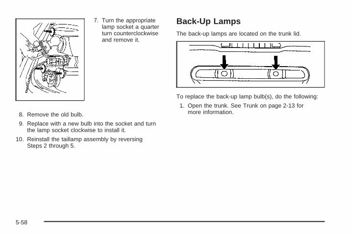
7. Turn the appropriatelamp socket a quarterturn counterclockwiseand remove it.
8. Remove the old bulb.
9. Replace with a new bulb into the socket and turnthe lamp socket clockwise to install it.
10. Reinstall the taillamp assembly by reversingSteps 2 through 5.
Back-Up LampsThe back-up lamps are located on the trunk lid.
To replace the back-up lamp bulb(s), do the following:
1. Open the trunk. See Trunk on page 2-13 formore information.
5-58

2. Turn the appropriate lamp socket a quarter turncounterclockwise and remove it.
3. Remove the old bulb.
4. Put the new bulb into the lamp socket.
5. Turn the bulb a quarter turn clockwise to reinstall it.
Replacement BulbsExterior Lamps Bulb Number
Back-Up Lamp 3157
Front Parking/Turn Signal Lamp 3757 KA* or5702 KA**
Front Sidemarker 194Headlamps
High-Beam Halogen 9005Low-Beam Halogen 9006
Stop/Taillamp/Turn Signal Lamps 3057* GT and Base Models with the Optional Fog Lamps* For Lamps Not Equipped with the Fog Function andGXP Models
For replacement bulbs not listed here, contactyour dealer.
5-59
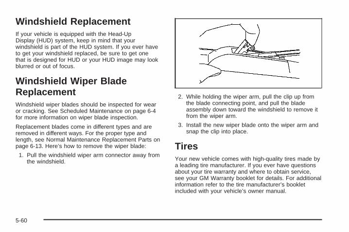
Windshield ReplacementIf your vehicle is equipped with the Head-UpDisplay (HUD) system, keep in mind that yourwindshield is part of the HUD system. If you ever haveto get your windshield replaced, be sure to get onethat is designed for HUD or your HUD image may lookblurred or out of focus.
Windshield Wiper BladeReplacementWindshield wiper blades should be inspected for wearor cracking. See Scheduled Maintenance on page 6-4for more information on wiper blade inspection.
Replacement blades come in different types and areremoved in different ways. For the proper type andlength, see Normal Maintenance Replacement Parts onpage 6-13. Here’s how to remove the wiper blade:
1. Pull the windshield wiper arm connector away fromthe windshield.
2. While holding the wiper arm, pull the clip up fromthe blade connecting point, and pull the bladeassembly down toward the windshield to remove itfrom the wiper arm.
3. Install the new wiper blade onto the wiper arm andsnap the clip into place.
TiresYour new vehicle comes with high-quality tires made bya leading tire manufacturer. If you ever have questionsabout your tire warranty and where to obtain service,see your GM Warranty booklet for details. For additionalinformation refer to the tire manufacturer’s bookletincluded with your vehicle’s owner manual.
5-60

{CAUTION:
Poorly maintained and improperly used tiresare dangerous.
• Overloading your tires can causeoverheating as a result of too muchfriction. You could have an air-out and aserious accident. See Loading YourVehicle on page 4-33.
• Underinflated tires pose the samedanger as overloaded tires. The resultingaccident could cause serious injury. Checkall tires frequently to maintain therecommended pressure. Tire pressureshould be checked when your tires arecold. See Inflation - Tire Pressure onpage 5-67.
• Overinflated tires are more likely to be cut,punctured, or broken by a suddenimpact — such as when you hit a pothole.Keep tires at the recommended pressure.
• Worn, old tires can cause accidents. Ifyour tread is badly worn, or if your tireshave been damaged, replace them.
Low-Profile Performance Tire (GXP)If your vehicle has P255/45R18 size tires on the frontwheels and P225/50R18 size tires on the rear wheels,they are classified as low-profile performance tires.These tires are designed for very responsive driving onwet or dry pavement. You may also notice moreroad noise with low-profile performance tires and thatthey tend to wear faster.
Notice: If your vehicle has low-profile tires, theyare more susceptible to damage from road hazardsor curb impact than standard profile tires. Tireand/or wheel assembly damage can occur whencoming into contact with road hazards like,potholes, or sharp edged objects, or when slidinginto a curb. Your GM warranty does not coverthis type of damage. Keep tires set to the correctinflation pressure and, when possible avoid contactwith curbs, potholes, and other road hazards.
5-61
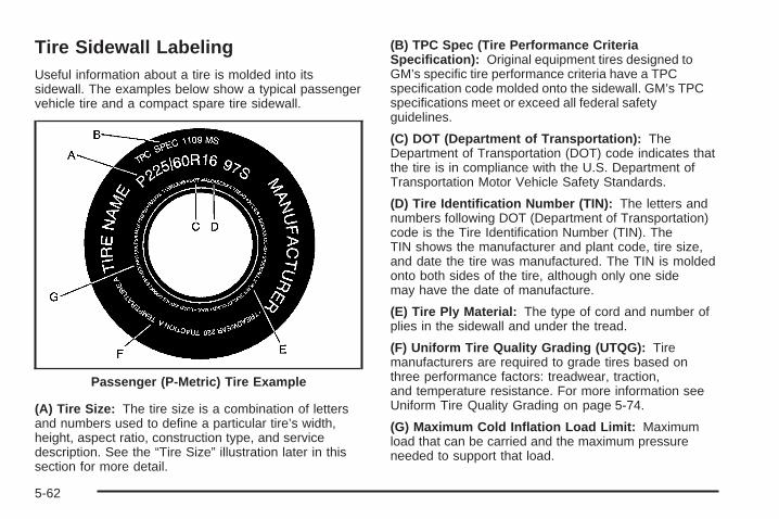
Tire Sidewall LabelingUseful information about a tire is molded into itssidewall. The examples below show a typical passengervehicle tire and a compact spare tire sidewall.
(A) Tire Size: The tire size is a combination of lettersand numbers used to define a particular tire’s width,height, aspect ratio, construction type, and servicedescription. See the “Tire Size” illustration later in thissection for more detail.
(B) TPC Spec (Tire Performance CriteriaSpecification): Original equipment tires designed toGM’s specific tire performance criteria have a TPCspecification code molded onto the sidewall. GM’s TPCspecifications meet or exceed all federal safetyguidelines.
(C) DOT (Department of Transportation): TheDepartment of Transportation (DOT) code indicates thatthe tire is in compliance with the U.S. Department ofTransportation Motor Vehicle Safety Standards.
(D) Tire Identification Number (TIN): The letters andnumbers following DOT (Department of Transportation)code is the Tire Identification Number (TIN). TheTIN shows the manufacturer and plant code, tire size,and date the tire was manufactured. The TIN is moldedonto both sides of the tire, although only one sidemay have the date of manufacture.
(E) Tire Ply Material: The type of cord and number ofplies in the sidewall and under the tread.
(F) Uniform Tire Quality Grading (UTQG): Tiremanufacturers are required to grade tires based onthree performance factors: treadwear, traction,and temperature resistance. For more information seeUniform Tire Quality Grading on page 5-74.
(G) Maximum Cold Inflation Load Limit: Maximumload that can be carried and the maximum pressureneeded to support that load.
Passenger (P-Metric) Tire Example
5-62
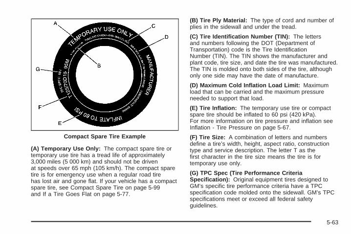
(A) Temporary Use Only: The compact spare tire ortemporary use tire has a tread life of approximately3,000 miles (5 000 km) and should not be drivenat speeds over 65 mph (105 km/h). The compact sparetire is for emergency use when a regular road tirehas lost air and gone flat. If your vehicle has a compactspare tire, see Compact Spare Tire on page 5-99and If a Tire Goes Flat on page 5-77.
(B) Tire Ply Material: The type of cord and number ofplies in the sidewall and under the tread.
(C) Tire Identification Number (TIN): The lettersand numbers following the DOT (Department ofTransportation) code is the Tire IdentificationNumber (TIN). The TIN shows the manufacturer andplant code, tire size, and date the tire was manufactured.The TIN is molded onto both sides of the tire, althoughonly one side may have the date of manufacture.
(D) Maximum Cold Inflation Load Limit: Maximumload that can be carried and the maximum pressureneeded to support that load.
(E) Tire Inflation: The temporary use tire or compactspare tire should be inflated to 60 psi (420 kPa).For more information on tire pressure and inflation seeInflation - Tire Pressure on page 5-67.
(F) Tire Size: A combination of letters and numbersdefine a tire’s width, height, aspect ratio, constructiontype and service description. The letter T as thefirst character in the tire size means the tire is fortemporary use only.
(G) TPC Spec (Tire Performance CriteriaSpecification): Original equipment tires designed toGM’s specific tire performance criteria have a TPCspecification code molded onto the sidewall. GM’s TPCspecifications meet or exceed all federal safetyguidelines.
Compact Spare Tire Example
5-63

Tire SizeThe following illustration shows an example of a typicalpassenger vehicle tire size.
(A) Passenger (P-Metric) Tire: The United Statesversion of a metric tire sizing system. The letter P as thefirst character in the tire size means a passengervehicle tire engineered to standards set by the U.S. Tireand Rim Association.
(B) Tire Width: The three-digit number indicates thetire section width in millimeters from sidewall to sidewall.
(C) Aspect Ratio: A two-digit number that indicatesthe tire height-to-width measurements. For example, ifthe tire size aspect ratio is 60, as shown in item C ofthe illustration, it would mean that the tire’s sidewall is60 percent as high as it is wide.
(D) Construction Code: A letter code is used toindicate the type of ply construction in the tire. Theletter R means radial ply construction; the letter D meansdiagonal or bias ply construction; and the letter B meansbelted-bias ply construction.
(E) Rim Diameter: Diameter of the wheel in inches.
(F) Service Description: These characters representthe load range and speed rating of the tire. The loadindex represents the load carry capacity a tire is certifiedto carry. The load index can range from 1 to 279. Thespeed rating is the maximum speed a tire is certifiedto carry a load. Speed ratings range from A to Z.
Tire Terminology and Definitions
Air Pressure: The amount of air inside the tire pressingoutward on each square inch of the tire. Air pressureis expressed in pounds per square inch (psi) orkilopascal (kPa).
Accessory Weight: This means the combined weightof optional accessories. Some examples of optionalaccessories are, automatic transmission, power steering,power brakes, power windows, power seats, and airconditioning.
Aspect Ratio: The relationship of a tire’s height toits width.
5-64

Belt: A rubber coated layer of cords that is locatedbetween the plies and the tread. Cords may be madefrom steel or other reinforcing materials.
Bead: The tire bead contains steel wires wrapped bysteel cords that hold the tire onto the rim.
Bias Ply Tire: A pneumatic tire in which the plies arelaid at alternate angles less than 90 degrees to thecenterline of the tread.
Cold Inflation Pressure: The amount of air pressure ina tire, measured in pounds per square inch (psi) orkilopascals (kPa) before a tire has built up heatfrom driving. See Inflation - Tire Pressure on page 5-67.
Curb Weight: This means the weight of a motorvehicle with standard and optional equipment includingthe maximum capacity of fuel, oil and coolant, butwithout passengers and cargo.
DOT Markings: A code molded into the sidewall of atire signifying that the tire is in compliance with the U.S.Department of Transportation (DOT) motor vehiclesafety standards. The DOT code includes the TireIdentification Number (TIN), an alphanumeric designatorwhich can also identify the tire manufacturer, productionplant, brand and date of production.
GVWR: Gross Vehicle Weight Rating, see LoadingYour Vehicle on page 4-33.
GAWR FRT: Gross Axle Weight Rating for the frontaxle, see Loading Your Vehicle on page 4-33.
GAWR RR: Gross Axle Weight Rating for the rear axle,see Loading Your Vehicle on page 4-33.
Intended Outboard Sidewall: The side of anasymmetrical tire, that must always face outward whenmounted on a vehicle.
Kilopascal (kPa): The metric unit for air pressure.
Light Truck (LT-Metric) Tire: A tire used on light dutytrucks and some multipurpose passenger vehicles.
Load Index: An assigned number ranging from1 to 279 that corresponds to the load carrying capacityof a tire.
Maximum Inflation Pressure: The maximum airpressure to which a cold tire may be inflated. Themaximum air pressure is molded onto the sidewall.
Maximum Load Rating: The load rating for a tire at themaximum permissible inflation pressure for that tire.
Maximum Loaded Vehicle Weight: The sum of curbweight; accessory weight; vehicle capacity weight;and production options weight.
Normal Occupant Weight: The number of occupants avehicle is designed to seat multiplied by 150 lbs (68 kg).See Loading Your Vehicle on page 4-33.
5-65

Occupant Distribution: Designated seating positions.
Outward Facing Sidewall: The side of anasymmetrical tire that has a particular side that facesoutward when mounted on a vehicle. The side of the tirethat contains a whitewall, bears white lettering, orbears manufacturer, brand, and/or model name moldingthat is higher or deeper than the same moldings onthe other sidewall of the tire.
Passenger (P-Metric) Tire: A tire used on passengercars and some light duty trucks and multipurposevehicles.
Recommended Inflation Pressure: Vehiclemanufacturer’s recommended tire inflation pressure andshown on the tire placard. See Inflation - Tire Pressureon page 5-67 and Loading Your Vehicle on page 4-33.
Radial Ply Tire: A pneumatic tire in which the ply cordsthat extend to the beads are laid at 90 degrees to thecenterline of the tread.
Rim: A metal support for a tire and upon which the tirebeads are seated.
Sidewall: The portion of a tire between the tread andthe bead.
Speed Rating: An alphanumeric code assigned to atire indicating the maximum speed at which a tirecan operate.
Traction: The friction between the tire and the roadsurface. The amount of grip provided.
Tread: The portion of a tire that comes into contactwith the road.
Treadwear Indicators: Narrow bands, sometimescalled wear bars, that show across the tread of a tirewhen only 1/16 inch (1.6 mm) of tread remains.See When It Is Time for New Tires on page 5-71.
UTQGS (Uniform Tire Quality Grading Standards): Atire information system that provides consumers withratings for a tire’s traction, temperature, and treadwear.Ratings are determined by tire manufacturers usinggovernment testing procedures. The ratings are moldedinto the sidewall of the tire. See Uniform Tire QualityGrading on page 5-74.
Vehicle Capacity Weight: The number of designatedseating positions multiplied by 150 lbs (68 kg) plusthe rated cargo load. See Loading Your Vehicleon page 4-33.
Vehicle Maximum Load on the Tire: Load on anindividual tire due to curb weight, accessory weight,occupant weight, and cargo weight.
Vehicle Placard: A label permanently attached to avehicle showing the vehicle’s capacity weight andthe original equipment tire size and recommendedinflation pressure. See “Tire and Loading InformationLabel” under Loading Your Vehicle on page 4-33.
5-66

Inflation - Tire PressureTires need the correct amount of air pressure tooperate effectively.
Notice: Do not let anyone tell you thatunder-inflation or over-inflation is all right. It is not.If your tires do not have enough air (under-inflation),you can get the following:
• Too much flexing
• Too much heat
• Tire overloading
• Premature or irregular wear
• Poor handling
• Reduced fuel economy
If your tires have too much air (over-inflation), youcan get the following:
• Unusual wear
• Poor handling
• Rough ride
• Needless damage from road hazards
A Tire and Loading Information label is attached to thevehicle’s center pillar (B-pillar), below the driver’sdoor latch. This label shows your vehicle’s originalequipment tires and the correct inflation pressures foryour tires when they are cold. The recommendedcold tire inflation pressure, shown on the label, is theminimum amount of air pressure needed to support yourvehicle’s maximum load carrying capacity.
For additional information regarding how much weightyour vehicle can carry, and an example of the tireand loading information label, see Loading Your Vehicleon page 4-33. How you load your vehicle affectsvehicle handling and ride comfort, never load yourvehicle with more weight than it was designed to carry.
When to CheckCheck your tires once a month or more. Do not forget tocheck the compact spare tire, it should be at 60 psi(420 kPa). For additional information regardingthe compact spare tire, see Compact Spare Tire onpage 5-99.
5-67

How to CheckUse a good quality pocket-type gage to check tirepressure. You cannot tell if your tires are properlyinflated simply by looking at them. Radial tiresmay look properly inflated even when they areunder-inflated. Check the tire’s inflation pressure whenthe tires are cold. Cold means your vehicle hasbeen sitting for at least three hours or driven no morethan 1 mile (1.6 km).
Remove the valve cap from the tire valve stem. Pressthe tire gage firmly onto the valve to get a pressuremeasurement. If the cold tire inflation pressure matchesthe recommended pressure on the Tire and LoadingInformation label, no further adjustment is necessary. Ifthe inflation pressure is low, add air until you reachthe recommended amount.
If you overfill the tire, release air by pushing on themetal stem in the center of the tire valve. Re-check thetire pressure with the tire gage.
Be sure to put the valve caps back on the valvestems. They help prevent leaks by keeping out dirtand moisture.
Tire Inflation Monitor SystemYour vehicle may have the Tire Inflation MonitorSystem (TIMS). The system is designed to alert thedriver when there is a large air pressure change inone tire, while the vehicle is being driven. TIMS detectsdifferences in tire rotation speeds that are caused bychanges in tire pressure. The system can alert youabout a low tire but it does not replace normaltire maintenance. See Tires on page 5-60. The TIMSlearns the pressure at each tire throughout the operatingspeed range of the vehicle. The system normallytakes between 45 and 90 minutes of driving to learn thetire pressures. This time may be longer depending onindividual driving habits. Learning need not beaccumulated during a single trip. Once learned, thesystem will remember the tire pressures until thesystem is reset.
5-68
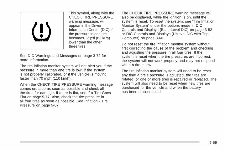
This symbol, along with theCHECK TIRE PRESSUREwarning message, willappear in the DriverInformation Center (DIC) ifthe pressure in one tirebecomes 12 psi (83 kPa)lower than the otherthree tires.
See DIC Warnings and Messages on page 3-72 formore information.
The tire inflation monitor system will not alert you if thepressure in more than one tire is low, if the systemis not properly calibrated, or if the vehicle is movingfaster than 70 mph (110 km/h).
When the CHECK TIRE PRESSURE warning messagecomes on, stop as soon as possible and check allthe tires for damage. If a tire is flat, see If a Tire GoesFlat on page 5-77. Also, check the tire pressure inall four tires as soon as possible. See Inflation - TirePressure on page 5-67.
The CHECK TIRE PRESSURE warning message willalso be displayed, while the ignition is on, until thesystem is reset. To reset the system, see “Tire InflationMonitor System” under the options mode in DICControls and Displays (Base Level DIC) on page 3-52or DIC Controls and Displays (Uplevel DIC with TripComputer) on page 3-60.
Do not reset the tire inflation monitor system withoutfirst correcting the cause of the problem and checkingand adjusting the pressure in all four tires. If thesystem is reset when the tire pressures are incorrect,the system will not work properly and may not respondwhen a tire is low.
The tire inflation monitor system will need to be resetany time a tire’s pressure is adjusted, the tires arerotated, or one or more tires is repaired or replaced. Thesystem will also need to be reset when new tires arepurchased for the vehicle and when the batteryhas been disconnected.
5-69

Tire Inspection and RotationTire rotation is not recommended if your vehicle is aGXP model equipped with P255/45R18 size tires onthe front wheels and P225/50R18 size tires on the rearwheels. Different tire sizes front to rear should notbe rotated.
Tire rotation is recommended if the original equipmenttires installed on your vehicle are of the same sizeand type on all four tire/wheel positions. Originalequipment tires of the same size and type should berotated every 5,000 to 8,000 miles (8 000 to 13 000 km).
Any time you notice unusual wear, rotate your vehicle’stires as soon as possible and check the wheelalignment. Also check for damaged tires or wheels. SeeWhen It Is Time for New Tires on page 5-71 andWheel Replacement on page 5-75 for more information.
The purpose of regular rotation is to achieve moreuniform wear for all tires on the vehicle. The first rotationis the most important. See Scheduled Maintenanceon page 6-4 for scheduled rotation intervals.
The correct rotation pattern shown here is only fornon-GXP tires.
Do not include the compact spare tire, if equipped, inyour vehicle’s tire rotation.
After the tires have been rotated, adjust the front andrear inflation pressures as shown on the Tire andLoading Information label, and reset the Tire InflationMonitor System. See Tire Inflation Monitor Systemon page 5-68 for additional information.
Rotation Pattern for Non-GXP Tires Only
5-70
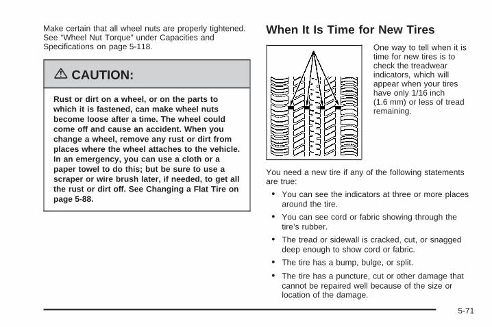
Make certain that all wheel nuts are properly tightened.See “Wheel Nut Torque” under Capacities andSpecifications on page 5-118.
{CAUTION:
Rust or dirt on a wheel, or on the parts towhich it is fastened, can make wheel nutsbecome loose after a time. The wheel couldcome off and cause an accident. When youchange a wheel, remove any rust or dirt fromplaces where the wheel attaches to the vehicle.In an emergency, you can use a cloth or apaper towel to do this; but be sure to use ascraper or wire brush later, if needed, to get allthe rust or dirt off. See Changing a Flat Tire onpage 5-88.
When It Is Time for New TiresOne way to tell when it istime for new tires is tocheck the treadwearindicators, which willappear when your tireshave only 1/16 inch(1.6 mm) or less of treadremaining.
You need a new tire if any of the following statementsare true:
• You can see the indicators at three or more placesaround the tire.
• You can see cord or fabric showing through thetire’s rubber.
• The tread or sidewall is cracked, cut, or snaggeddeep enough to show cord or fabric.
• The tire has a bump, bulge, or split.
• The tire has a puncture, cut or other damage thatcannot be repaired well because of the size orlocation of the damage.
5-71

Buying New TiresGM has developed and matched specific tires for yourvehicle. The original equipment tires installed onyour vehicle, when it was new, were designed to meetGeneral Motors Tire Performance Criteria Specification(TPC spec) system rating. If you need replacementtires, GM strongly recommends that you get tires withthe same TPC Spec rating. This way, your vehiclewill continue to have tires that are designed to give thesame performance and vehicle safety, during normaluse, as the original tires.
GM’s exclusive TPC Spec system considers over adozen critical specifications that impact the overallperformance of your vehicle, including brake systemperformance, ride and handling, traction control, and tirepressure monitoring performance. GM’s TPC Specnumber is molded onto the tire’s sidewall by thetire manufacturer. If the tires have an all-season treaddesign, the TPC spec number will be followed by an MSfor mud and snow. See Tire Sidewall Labeling onpage 5-62 for additional information.
{CAUTION:
Mixing tires could cause you to lose controlwhile driving. If you mix tires of different sizes(other than those originally installed on yourvehicle), brands, or types (radial andbias-belted tires), the vehicle may not handleproperly, and you could have a crash. Usingtires of different sizes (other than thoseoriginally installed on your vehicle) may alsocause damage to your vehicle. Be sure to usethe correct size, brand, and type tires on allwheels. If your vehicle has a compact sparetire, it is all right to drive your vehicle with thecompact spare temporarily. It was developedfor use on your vehicle. See Compact SpareTire on page 5-99.
5-72

{CAUTION:
If you use bias-ply tires on your vehicle, thewheel rim flanges could develop cracks aftermany miles of driving. A tire and/or wheelcould fail suddenly, causing a crash. Use onlyradial-ply tires with the wheels on your vehicle.
If you must replace your vehicle’s tires with those thatdo not have a TPC Spec number, make sure theyare the same size, load range, speed rating, andconstruction type (radial and bias-belted tires) as yourvehicle’s original tires.
Your vehicle’s original equipment tires are listed on theTire and Loading Information Label. This label isattached to the vehicle’s center pillar (B-pillar). SeeLoading Your Vehicle on page 4-33, for more informationabout the Tire and Loading Information Label and itslocation on your vehicle.
Different Size Tires and WheelsIf you add wheels or tires that are a different size thanyour original equipment wheels and tires, this mayaffect the way your vehicle performs, including itsbraking, ride and handling characteristics, stability andresistance to rollover. Additionally, if your vehiclehas electronic systems such as, antilock brakes; tractioncontrol; and electronic stability control, the performanceof these systems can be affected.
{CAUTION:
If you add different sized wheels, your vehiclemay not provide an acceptable level ofperformance and safety if tires notrecommended for those wheels are selected.You may increase the chance that you willcrash and suffer serious injury. Only use GMspecific wheel and tire systems developed foryour vehicle, and have them properly installedby a GM certified technician.
See Buying New Tires on page 5-72 and Accessoriesand Modifications on page 5-3 for additional information.
5-73

Uniform Tire Quality GradingQuality grades can be found where applicable on thetire sidewall between tread shoulder and maximumsection width. For example:
Treadwear 200 Traction AA Temperature AThe following information relates to the systemdeveloped by the United States National HighwayTraffic Safety Administration, which grades tires bytreadwear, traction and temperature performance. (Thisapplies only to vehicles sold in the United States.)The grades are molded on the sidewalls of mostpassenger car tires. The Uniform Tire Quality Gradingsystem does not apply to deep tread, winter-typesnow tires, space-saver or temporary use spare tires,tires with nominal rim diameters of 10 to 12 inches(25 to 30 cm), or to some limited-production tires.
While the tires available on General Motors passengercars and light trucks may vary with respect to thesegrades, they must also conform to federal safetyrequirements and additional General Motors TirePerformance Criteria (TPC) standards.
TreadwearThe treadwear grade is a comparative rating based onthe wear rate of the tire when tested under controlledconditions on a specified government test course.For example, a tire graded 150 would wear one anda half (1.5) times as well on the government course asa tire graded 100. The relative performance of tiresdepends upon the actual conditions of their use,however, and may depart significantly from the normdue to variations in driving habits, service practices anddifferences in road characteristics and climate.
Traction – AA, A, B, CThe traction grades, from highest to lowest, are AA, A,B, and C. Those grades represent the tire’s abilityto stop on wet pavement as measured under controlledconditions on specified government test surfaces ofasphalt and concrete. A tire marked C may have poortraction performance. Warning: The traction gradeassigned to this tire is based on straight-ahead brakingtraction tests, and does not include acceleration,cornering, hydroplaning, or peak traction characteristics.
5-74

Temperature – A, B, CThe temperature grades are A (the highest), B, and C,representing the tire’s resistance to the generationof heat and its ability to dissipate heat when testedunder controlled conditions on a specified indoorlaboratory test wheel. Sustained high temperature cancause the material of the tire to degenerate andreduce tire life, and excessive temperature can lead tosudden tire failure. The grade C corresponds to alevel of performance which all passenger car tires mustmeet under the Federal Motor Vehicle Safety StandardNo. 109. Grades B and A represent higher levels ofperformance on the laboratory test wheel than theminimum required by law.
Warning: The temperature grade for this tire isestablished for a tire that is properly inflated and notoverloaded. Excessive speed, underinflation, orexcessive loading, either separately or in combination,can cause heat buildup and possible tire failure.
Wheel Alignment and Tire BalanceThe tires and wheels on your vehicle were alignedand balanced carefully at the factory to give you thelongest tire life and best overall performance.Adjustments to wheel alignment and tire balancing willnot be necessary on a regular basis. However, ifyou notice unusual tire wear or your vehicle pulling toone side or the other, the alignment may need tobe checked. If you notice your vehicle vibrating whendriving on a smooth road, your tires and wheelsmay need to be rebalanced. See your dealer forproper diagnosis.
Wheel ReplacementReplace any wheel that is bent, cracked or badly rustedor corroded. If wheel nuts keep coming loose, thewheel, wheel bolts and wheel nuts should be replaced.If the wheel leaks air, replace it (except somealuminum wheels, which can sometimes be repaired).See your dealer if any of these conditions exist.
Your dealer will know the kind of wheel you need.
5-75

Each new wheel should have the same load-carryingcapacity, diameter, width, offset and be mountedthe same way as the one it replaces.
If you need to replace any of your wheels, wheel boltsor wheel nuts, replace them only with new GMoriginal equipment parts. This way, you will be sure tohave the right wheel, wheel bolts and wheel nutsfor your vehicle.
{CAUTION:
Using the wrong replacement wheels, wheelbolts, or wheel nuts on your vehicle can bedangerous. It could affect the braking andhandling of your vehicle, make your tires loseair and make you lose control. You could havea collision in which you or others could beinjured. Always use the correct wheel, wheelbolts and wheel nuts for replacement.
Notice: The wrong wheel can also cause problemswith bearing life, brake cooling, speedometer orodometer calibration, headlamp aim, bumper height,vehicle ground clearance, and tire or tire chainclearance to the body and chassis.
See Changing a Flat Tire on page 5-88 for moreinformation.
Used Replacement Wheels
{CAUTION:
Putting a used wheel on your vehicle isdangerous. You cannot know how it has beenused or how far it has been driven. It could failsuddenly and cause a crash. If you have toreplace a wheel, use a new GM originalequipment wheel.
5-76

Tire Chains
{CAUTION:
If your vehicle has P225/55R17, P255/45R18 orP225/50R18 size tires, do not use tire chains,there is not enough clearance.
Tire chains used on a vehicle without theproper amount of clearance can cause damageto the brakes, suspension or other vehicleparts. The area damaged by the tire chainscould cause you to lose control of your vehicleand you or others may be injured in a crash.
Use another type of traction device only if itsmanufacturer recommends it for use on yourvehicle and tire size combination and roadconditions. Follow that manufacturer’sinstructions. To help avoid damage to yourvehicle, drive slowly, readjust or remove thedevice if it is contacting your vehicle, and donot spin your wheels.
If you do find traction devices that will fit,install them on the front tires.
Notice: If your vehicle does not have P225/55R17,P255/45R18 or P225/50R18 size tires, use tire chainsonly where legal and only when you must. Use onlySAE Class S-type chains that are the proper size foryour tires. Install them on the front tires and tightenthem as tightly as possible with the ends securelyfastened. Drive slowly and follow the chainmanufacturer’s instructions. If you can hear thechains contacting your vehicle, stop and retightenthem. If the contact continues, slow down until itstops. Driving too fast or spinning the wheels withchains on will damage your vehicle.
If a Tire Goes FlatIt is unusual for a tire to blowout while you are driving,especially if you maintain your tires properly. SeeTires on page 5-60. If air goes out of a tire, it is muchmore likely to leak out slowly. But if you should everhave a blowout, here are a few tips about what to expectand what to do:
If a front tire fails, the flat tire will create a drag thatpulls the vehicle toward that side. Take your foot off theaccelerator pedal and grip the steering wheel firmly.Steer to maintain lane position, and then gently brake toa stop well out of the traffic lane.
5-77
A rear blowout, particularly on a curve, acts much like askid and may require the same correction you’d usein a skid. In any rear blowout, remove your foot from theaccelerator pedal. Get the vehicle under control bysteering the way you want the vehicle to go. It may bevery bumpy and noisy, but you can still steer. Gentlybrake to a stop, well off the road if possible.
If a tire goes flat, and your vehicle has a spare tire, seeChanging a Flat Tire on page 5-88. This informationshows you how to use your vehicle’s tire changingequipment and how to change a flat tire safely.
{CAUTION:
Lifting a vehicle and getting under it to domaintenance or repairs is dangerous withoutthe appropriate safety equipment and training.The jack provided with your vehicle isdesigned only for changing a flat tire. If it isused for anything else, you or others could bebadly injured or killed if the vehicle slips offthe jack. Use the jack provided with yourvehicle only for changing a flat tire.
If a Tire Goes Flat (GXP)GXP models have no spare tire, no tire changingequipment, and no place for storing a spare or flat tire. If atire goes flat, avoid further tire and wheel damage bydriving slowly to a level place and stopping. Then do this:
1. Turn on the hazard warning flashers. See HazardWarning Flashers on page 3-6.
2. Park your vehicle. Set the parking brake firmly andput the shift lever in PARK (P). See Shifting IntoPark (P) on page 2-31 for additional information.
3. Turn off the engine.
4. Inspect the flat tire.
If the tire has been separated from the wheel or hasdamaged sidewalls or large tears that allow rapidair loss, call a tire repair facility. See RoadsideAssistance Program on page 7-6.
If the flat tire is due to a slow leak caused by a nail orother similar road hazard, the tire inflator kit may be usedto temporarily repair the damaged tire. The kit uses aliquid tire sealant to seal small punctures in the tread areaof the tire. The flat tire is then inflated to at least 30 psi(207 kPa) and driven to evenly distribute the tire sealant.
5-78
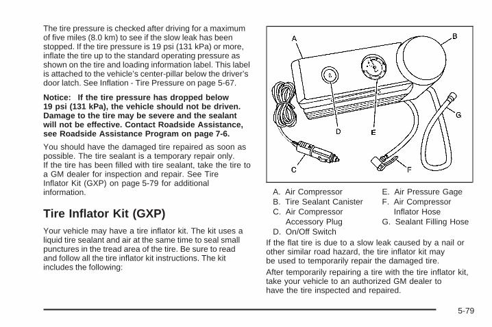
The tire pressure is checked after driving for a maximumof five miles (8.0 km) to see if the slow leak has beenstopped. If the tire pressure is 19 psi (131 kPa) or more,inflate the tire up to the standard operating pressure asshown on the tire and loading information label. This labelis attached to the vehicle’s center-pillar below the driver’sdoor latch. See Inflation - Tire Pressure on page 5-67.
Notice: If the tire pressure has dropped below19 psi (131 kPa), the vehicle should not be driven.Damage to the tire may be severe and the sealantwill not be effective. Contact Roadside Assistance,see Roadside Assistance Program on page 7-6.
You should have the damaged tire repaired as soon aspossible. The tire sealant is a temporary repair only.If the tire has been filled with tire sealant, take the tire toa GM dealer for inspection and repair. See TireInflator Kit (GXP) on page 5-79 for additionalinformation.
Tire Inflator Kit (GXP)Your vehicle may have a tire inflator kit. The kit uses aliquid tire sealant and air at the same time to seal smallpunctures in the tread area of the tire. Be sure to readand follow all the tire inflator kit instructions. The kitincludes the following:
A. Air CompressorB. Tire Sealant CanisterC. Air Compressor
Accessory PlugD. On/Off Switch
E. Air Pressure GageF. Air Compressor
Inflator HoseG. Sealant Filling Hose
If the flat tire is due to a slow leak caused by a nail orother similar road hazard, the tire inflator kit maybe used to temporarily repair the damaged tire.After temporarily repairing a tire with the tire inflator kit,take your vehicle to an authorized GM dealer tohave the tire inspected and repaired.
5-79

Accessing the Tire Inflator KitTo access the tire inflator kit, do the following:
1. Open the trunk. See Trunk on page 2-13 for moreinformation.
2. Locate the tire inflator kit by lifting up the carpet.3. Remove the inflator
kit cover by turningthe center nutcounterclockwise.
4. Remove the inflator kit by pulling it straight out ofthe foam container.
5-80

Tire SealantThe kit contains a liquid sealant that when injected into aflat tire, may temporarily repair nail holes or cuts in thetread area of the tire. The tire sealant cannot repair tiredamage caused while driving on a flat tire or a tire thathas had a “blow out” or a tire that has punctures in thesidewall areas. The tire sealant solution is to be used fora single tire and can only be used once.
Check the tire sealant expiration date on the sealantcanister. The sealant may not be as effective beyond theexpiration date. If needed, see your GM dealer for areplacement canister.
After temporarily repairing a tire using the tire sealant,take your vehicle to an authorized GM dealer to have thetire inspected and repaired.
Using the Tire Inflator KitTo use the tire inflator kit, do the following:
1. Place the inflator kit on the ground and unwrap thesealant filling hose from the compressor.
2. Remove the air compressor accessory plug fromthe unit. To do this, pull the top portion of thewrapped cord out first, then the bottom, then unsnapthe plug. Do not insert the plug into an accessoryoutlet yet.
3. Remove the valve stem cap from the flat tire byturning it counterclockwise.If an object, such as a nail, has penetrated the tire,do not remove it.
5-81

4. Attach the sealant filling hose (A) onto the tire valvestem. Turn it clockwise until it is tight.Make sure the inflator kit on/off switch (B) is in theO (off) position.
5. Plug the air compressor accessory plug (C) into anaccessory power outlet in the vehicle. SeeAccessory Power Outlet(s) on page 3-24 for moreinformation.
{CAUTION:
Idling the engine in a closed-in place or withthe climate control system off can causedeadly carbon monoxide (CO). See EngineExhaust on page 2-33.
6. Start the vehicle. See Starting the Engine onpage 2-23 for more information. The vehicle must berunning while using the air compressor.
{CAUTION:
Inflating something too much can make itexplode, and you or others could be injured.Be sure to read the inflator instructions, andinflate the tire to its recommended pressure.Do not exceed 36 psi (248 kPa).
7. Move the inflator kit switch to the I (on) position.The inflator kit will force sealant and air into thetire. Sealant may leak from the puncture hole untilthe vehicle is driven and the hole has sealed.
5-82
8. Make sure there is a proper connection betweenthe tire valve stem and the sealant filling hose bylooking at the air pressure gage. If there is nota pressure reading while the compressor is running,the connection between the inflator kit and thetire is bad.Check the attachment between the sealant fillinghose and the tire valve stem.
9. Inflate the tire up to the recommended inflationpressure, found on the Tire and Loading Informationlabel located on the vehicle’s center pillar (B-pillar)below the vehicle’s door latch, using the air pressuregage on the top of the unit as a guide.The pressure gage reading is slightly high while thecompressor is on. Turn the compressor off to getan accurate pressure reading.
Notice: If the recommended pressure cannot bereached after 15 minutes, the vehicle should not bedriven farther. Damage to the tire is severe andthe sealant will not be effective. Remove theair compressor plug from the accessory poweroutlet and unscrew the inflating hose from the tirevalve. See Roadside Assistance Program onpage 7-6.
10. Move the inflator kit switch to the O (off) positiononce the correct tire pressure is obtained.
11. Turn off the engine.
12. Unplug the air compressor accessory plug from theaccessory power outlet in the vehicle.
13. Disconnect the sealant filling hose from the tirevalve stem, by turning it counterclockwise, andreplace the tire valve stem cap.Be careful when handling the tire inflatorcomponents as they may be hot after usage.
14. Wrap the sealant filling hose around the aircompressor channel to stow it in its original location.
5-83

15. Stow the air compressor accessory plug back in theair compressor. To do this, wrap the air compressoraccessory plug, snap in the plug, and then pushin the bottom and then the top of the wrappedair compressor accessory plug.
16. If the flat tire was ableto inflate to therecommended inflationpressure, remove themaximum speed labelfrom the sealantcanister.
Place it in a highly visible location such as theinside of the upper left corner of the windshield orto the face of the radio/clock.The maximum speed label reminds you to drivecautiously and not to exceed 55 mph (90 km/h) untilyou have the damaged tire inspected and repaired.
{CAUTION:
Storing the tire inflator kit or other equipment inthe passenger compartment of the vehicle couldcause injury. In a sudden stop or collision,loose equipment could strike someone. Storethe tire inflator kit in the proper place.
17. Return the equipment to the proper storage locationin the trunk of your vehicle.
5-84
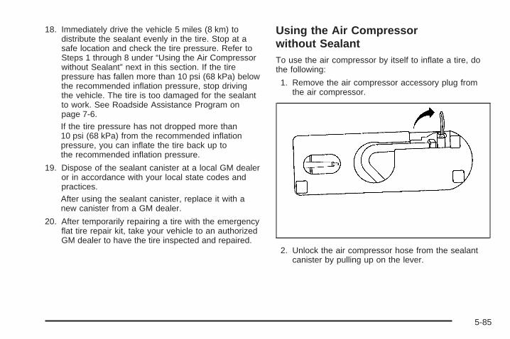
18. Immediately drive the vehicle 5 miles (8 km) todistribute the sealant evenly in the tire. Stop at asafe location and check the tire pressure. Refer toSteps 1 through 8 under “Using the Air Compressorwithout Sealant” next in this section. If the tirepressure has fallen more than 10 psi (68 kPa) belowthe recommended inflation pressure, stop drivingthe vehicle. The tire is too damaged for the sealantto work. See Roadside Assistance Program onpage 7-6.If the tire pressure has not dropped more than10 psi (68 kPa) from the recommended inflationpressure, you can inflate the tire back up tothe recommended inflation pressure.
19. Dispose of the sealant canister at a local GM dealeror in accordance with your local state codes andpractices.After using the sealant canister, replace it with anew canister from a GM dealer.
20. After temporarily repairing a tire with the emergencyflat tire repair kit, take your vehicle to an authorizedGM dealer to have the tire inspected and repaired.
Using the Air Compressorwithout SealantTo use the air compressor by itself to inflate a tire, dothe following:
1. Remove the air compressor accessory plug fromthe air compressor.
2. Unlock the air compressor hose from the sealantcanister by pulling up on the lever.
5-85
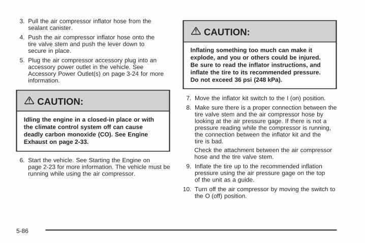
3. Pull the air compressor inflator hose from thesealant canister.
4. Push the air compressor inflator hose onto thetire valve stem and push the lever down tosecure in place.
5. Plug the air compressor accessory plug into anaccessory power outlet in the vehicle. SeeAccessory Power Outlet(s) on page 3-24 for moreinformation.
{CAUTION:
Idling the engine in a closed-in place or withthe climate control system off can causedeadly carbon monoxide (CO). See EngineExhaust on page 2-33.
6. Start the vehicle. See Starting the Engine onpage 2-23 for more information. The vehicle must berunning while using the air compressor.
{CAUTION:
Inflating something too much can make itexplode, and you or others could be injured.Be sure to read the inflator instructions, andinflate the tire to its recommended pressure.Do not exceed 36 psi (248 kPa).
7. Move the inflator kit switch to the I (on) position.
8. Make sure there is a proper connection between thetire valve stem and the air compressor hose bylooking at the air pressure gage. If there is not apressure reading while the compressor is running,the connection between the inflator kit and thetire is bad.Check the attachment between the air compressorhose and the tire valve stem.
9. Inflate the tire up to the recommended inflationpressure using the air pressure gage on the topof the unit as a guide.
10. Turn off the air compressor by moving the switch tothe O (off) position.
5-86

{CAUTION:
Storing the tire inflator kit or other equipmentin the passenger compartment of the vehiclecould cause injury. In a sudden stop orcollision, loose equipment could strikesomeone. Store the tire inflator kit in theproper place.
11. Disconnect the compressor inflator hose and wrapthe hose in the bottom of the inflator kit.
12. Place the equipment in the original location in thetrunk of your vehicle.
Removal and Installation of theSealant CanisterTo remove the sealant canister, do the following:
1. Unlock the air compressor inflator hose from thesealant canister by pulling the lever up.
2. Disconnect the air compressor inflator hose fromthe sealant canister.
3. Unwrap the sealant filling hose from thecompressor.
5-87

4. Turn the sealant canister so the inflator filling hoseis aligned with the slot in the compressor.
5. Lift the sealant canister from the air compressorand replace with a new sealant canister. Seeyour GM dealer for more information.
To install a new sealant canister, do the following:
1. Align the sealant filling hose with the slot in the aircompressor.
2. Push the sealant canister down and rotate itclockwise.
3. Wrap the sealant filling hose around the aircompressor channel to stow it in its original location.
4. Push the air compressor inflator hose onto thesealant canister inlet and push the lever down.
Changing a Flat TireIf a tire goes flat, avoid further tire and wheel damageby driving slowly to a level place. Turn on your vehicle’shazard warning flashers. See Hazard Warning Flasherson page 3-6 for more information.
5-88

{CAUTION:
Changing a tire can be dangerous. The vehiclecan slip off the jack and roll over or fall on youor other people. You and they could be badlyinjured or even killed. Find a level place tochange your tire. To help prevent the vehiclefrom moving:
1. Set the parking brake firmly.
2. Put the shift lever in PARK (P).
3. Turn off the engine and do not restartwhile the vehicle is raised.
4. Do not allow passengers to remain inthe vehicle.
To be even more certain the vehicle will notmove, you should put blocks at the front andrear of the tire farthest away from the onebeing changed. That would be the tire, on theother side, at the opposite end of the vehicle.
When your vehicle has a flat tire, use the followingexample as a guide to assist you in the placement ofwheel blocks.
The following information will tell you next how to usethe jack and change a tire.
5-89

Removing the Spare Tire and ToolsThe equipment needed to change a tire is located inthe trunk.
1. Open the trunk. See Trunk on page 2-13 for moreinformation.
2. Remove the convenience net, if equipped, byremoving the net hook attachments.
3. Lift up the carpet.4. Turn the center nut on
the compact spare tirecover counterclockwiseto remove it.
5. Remove the cover.
6. Remove the compact spare tire. See CompactSpare Tire on page 5-99 for more information.
7. Turn the nut holding the jack counterclockwise andremove it. Then remove the jack and wrench.
5-90
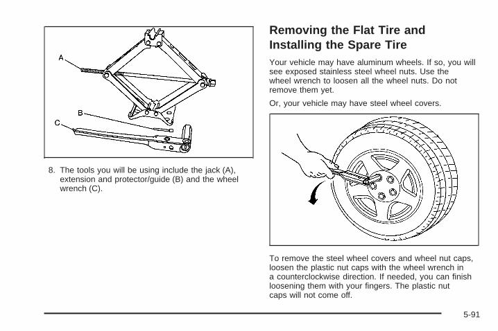
8. The tools you will be using include the jack (A),extension and protector/guide (B) and the wheelwrench (C).
Removing the Flat Tire andInstalling the Spare TireYour vehicle may have aluminum wheels. If so, you willsee exposed stainless steel wheel nuts. Use thewheel wrench to loosen all the wheel nuts. Do notremove them yet.
Or, your vehicle may have steel wheel covers.
To remove the steel wheel covers and wheel nut caps,loosen the plastic nut caps with the wheel wrench ina counterclockwise direction. If needed, you can finishloosening them with your fingers. The plastic nutcaps will not come off.
5-91
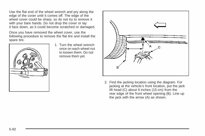
Use the flat end of the wheel wrench and pry along theedge of the cover until it comes off. The edge of thewheel cover could be sharp, so do not try to remove itwith your bare hands. Do not drop the cover or layit face down, as it could become scratched or damaged.
Once you have removed the wheel cover, use thefollowing procedure to remove the flat tire and install thespare tire.
1. Turn the wheel wrenchonce on each wheel nutto loosen them. Do notremove them yet.
2. Find the jacking location using the diagram. Forjacking at the vehicle’s front location, put the jacklift head (C) about 6 inches (15 cm) from therear edge of the front wheel opening (B). Line upthe jack with the arrow (A) as shown.
5-92

For jacking at the vehicle’s rear location, put thejack lift head (B) about 9 inches (23 cm) fromthe front edge of the rear wheel opening (C). Lineup the jack with the arrow (A) as shown.
3. Put the compact spare tire near you.
{CAUTION:
Getting under a vehicle when it is jacked up isdangerous. If the vehicle slips off the jack youcould be badly injured or killed. Never get undera vehicle when it is supported only by a jack.
{CAUTION:
Raising your vehicle with the jack improperlypositioned can damage the vehicle and evenmake the vehicle fall. To help avoid personalinjury and vehicle damage, be sure to fit thejack lift head into the proper location beforeraising the vehicle.
5-93

{CAUTION:
Lifting a vehicle and getting under it to domaintenance or repairs is dangerous withoutthe appropriate safety equipment and training.The jack provided with your vehicle isdesigned only for changing a flat tire. If it isused for anything else, you or others could bebadly injured or killed if the vehicle slips offthe jack. Use the jack provided with yourvehicle only for changing a flat tire.
4. Raise the vehicle by turning the jack handleclockwise. Raise the vehicle far enough off theground for the compact spare tire to fit underneaththe wheel well of the vehicle.
5. Remove all wheel nuts and take off the flat tire.
5-94

{CAUTION:
Rust or dirt on the wheel, or on the parts towhich it is fastened, can make the wheel nutsbecome loose after a time. The wheel couldcome off and cause an accident. When youchange a wheel, remove any rust or dirt fromthe places where the wheel attaches to thevehicle. In an emergency, you can use a clothor a paper towel to do this; but be sure to usea scraper or wire brush later, if needed, to getall the rust or dirt off.
6. Remove any rust or dirtfrom the wheel bolts,mounting surfacesand spare wheel.
7. Install the compact spare tire.
{CAUTION:
Never use oil or grease on studs or nuts. Ifyou do, the nuts might come loose. Your wheelcould fall off, causing a serious accident.
8. Reinstall the wheel nutswith the rounded end ofthe nuts toward thewheel. Tighten each nutby hand until the wheelis held against the hub.
5-95
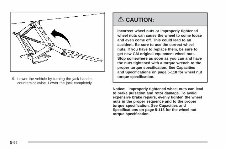
9. Lower the vehicle by turning the jack handlecounterclockwise. Lower the jack completely.
{CAUTION:
Incorrect wheel nuts or improperly tightenedwheel nuts can cause the wheel to come looseand even come off. This could lead to anaccident. Be sure to use the correct wheelnuts. If you have to replace them, be sure toget new GM original equipment wheel nuts.Stop somewhere as soon as you can and havethe nuts tightened with a torque wrench to theproper torque specification. See Capacitiesand Specifications on page 5-118 for wheel nuttorque specification.
Notice: Improperly tightened wheel nuts can leadto brake pulsation and rotor damage. To avoidexpensive brake repairs, evenly tighten the wheelnuts in the proper sequence and to the propertorque specification. See Capacities andSpecifications on page 5-118 for the wheel nuttorque specification.
5-96

10. Tighten the wheel nutsfirmly in a crisscrosssequence as shown.
Notice: Wheel covers will not fit on your compactspare. If you try to put a wheel cover on the compactspare, you could damage the cover or the spare.
Do not try to put the wheel cover on the compact sparetire. It will not fit. Store the wheel cover in the trunkuntil the flat tire is repaired or replaced.
Storing a Flat or Spare Tireand Tools
{CAUTION:
Storing a jack, a tire, or other equipment in thepassenger compartment of the vehicle couldcause injury. In a sudden stop or collision,loose equipment could strike someone. Storeall these in the proper place.
After the compact spare tire is put on the vehicle, storethe flat tire in the trunk. Use the following procedureto secure it in the trunk. When storing a full-size tire, usethe extension and protector/guide, located in the foamholder to help avoid wheel surface damage.
5-97
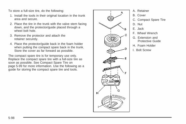
To store a full-size tire, do the following:
1. Install the tools in their original location in the trunkarea and secure.
2. Place the tire in the trunk with the valve stem facingdown, and the protector/guide placed through awheel bolt hole.
3. Remove the protector and attach theretainer securely.
4. Place the protector/guide back in the foam holderwhen putting the compact spare back in the trunk.Store the cover as far forward as possible.
The compact spare tire is for temporary use only.Replace the compact spare tire with a full-size tire assoon as possible. See Compact Spare Tire onpage 5-99 for more information. Use the following as aguide for storing the compact spare tire and tools.
A. RetainerB. CoverC. Compact Spare TireD. NutE. JackF. Wheel WrenchG. Extension and
Protective GuideH. Foam HolderI. Bolt Screw
5-98
Compact Spare TireAlthough the compact spare tire was fully inflated whenthe vehicle was new, it can lose air after a time.Check the inflation pressure regularly. It should be60 psi (420 kPa).After installing the compact spare on the vehicle, stopas soon as possible and make sure the spare tireis correctly inflated. The compact spare is made toperform well at speeds up to 65 mph (105 km/h)for distances up to 3,000 miles (5 000 km), so you canfinish your trip and have the full-size tire repaired orreplaced at your convenience. Of course, it is bestto replace the spare with a full-size tire as soon aspossible. The spare tire will last longer and be in goodshape in case it is needed again.
Notice: When the compact spare is installed, donot take your vehicle through an automatic car washwith guide rails. The compact spare can getcaught on the rails. That can damage the tire andwheel, and maybe other parts of your vehicle.Do not use the compact spare on other vehicles.And do not mix the compact spare tire or wheel withother wheels or tires. They will not fit. Keep thespare tire and its wheel together.
Notice: Tire chains will not fit your compact spare.Using them can damage your vehicle and candamage the chains too. Do not use tire chains onyour compact spare.
Appearance Care
Cleaning the Inside of Your VehicleYour vehicle’s interior will continue to look its best ifit is cleaned often. Although not always visible, dust anddirt can accumulate on your upholstery. Dirt candamage carpet, fabric, leather, and plastic surfaces.Regular vacuuming is recommended to remove particlesfrom your upholstery. It is important to keep yourupholstery from becoming and remaining heavily soiled.Soils should be removed as quickly as possible. Yourvehicle’s interior may experience extremes of heatthat could cause stains to set rapidly.
Lighter colored interiors may require more frequentcleaning. Use care because newspapers and garmentsthat transfer color to your home furnishings may alsotransfer color to your vehicle’s interior.
When cleaning your vehicle’s interior, only use cleanersspecifically designed for the surfaces being cleaned.Permanent damage may result from using cleaners onsurfaces for which they were not intended. Use glasscleaner only on glass. Remove any accidental over-sprayfrom other surfaces immediately. To prevent over-spray,apply cleaner directly to the cleaning cloth.
5-99

Notice: If you use abrasive cleaners when cleaningglass surfaces on your vehicle, you could scratchthe glass and/or cause damage to the integratedradio antenna and the rear window defogger. Whencleaning the glass on your vehicle, use only asoft cloth and glass cleaner.
Many cleaners contain solvents that may becomeconcentrated in your vehicle’s breathing space. Beforeusing cleaners, read and adhere to all safetyinstructions on the label. While cleaning your vehicle’sinterior, maintain adequate ventilation by openingyour vehicle’s doors and windows.
Dust may be removed from small buttons and knobsusing a small brush with soft bristles.
Your GM dealer has a product for cleaning yourvehicle’s glass. Should it become necessary, you canalso obtain a product from your GM dealer to removeodors from your vehicle’s upholstery.
Do not clean your vehicle using the following cleanersor techniques:
• Never use a knife or any other sharp object toremove a soil from any interior surface.
• Never use a stiff brush. It can cause damage toyour vehicle’s interior surfaces.
• Never apply heavy pressure or rub aggressivelywith a cleaning cloth. Use of heavy pressurecan damage your interior and does not improve theeffectiveness of soil removal.
• Use only mild, neutral-pH soaps. Avoid laundrydetergents or dishwashing soaps with degreasers.Using too much soap will leave a residue thatleaves streaks and attracts dirt. For liquid cleaners,about 20 drops per gallon (3.78 L) of water is agood guide.
• Do not heavily saturate your upholsterywhile cleaning.
• Damage to your vehicle’s interior may result fromthe use of many organic solvents such as naptha,alcohol, etc.
5-100

Fabric/Carpet
Cleaning Fabric/CarpetUse a vacuum cleaner often to get rid of dust and loosedirt. Wipe vinyl, leather, plastic, and painted surfaceswith a clean, damp cloth.
Your GM dealer has cleaners for the cleaning of fabricand carpet. They will clean normal spots and stainsvery well.
If the vehicle has the Ultra Lux® suede fabric, follow thelisted procedures except do not use any solvents ordry cleaning products.
Here are some cleaning tips:
• Always read the instructions on the cleaner label.
• Clean up stains as soon as you can, beforethey set.
• Carefully scrape off any excess stain.
• Use a clean cloth or sponge, and change to aclean area often. A soft brush may be used if stainsare stubborn.
• To avoid forming a ring on fabric after spot cleaning,clean the entire area immediately or it will set.
Most stains can be removed with club soda water. Toclean, use the following instructions:
1. For liquids: blot with a clean, soft white cloth.For solids: remove as much as possible andthen vacuum or brush.
2. Apply club soda water to a clean, soft whitecloth. Do not over-saturate; the cloth should notdrip water.
3. Clean the entire area. Avoid getting the fabrictoo wet.
4. Start cleaning from the seams into the stain toavoid a ring effect.
5. Continue cleaning, using a clean area of the clotheach time it becomes soiled.
6. When the stain is removed, blot the cleaned areawith another dry clean, soft white cloth.
5-101

Using Cleaner on Fabric1. First, try the cleaner in an inconspicuous area to
make sure the cleaner does not affect the color ofthe fabric.
2. For liquids: blot the stain with a clean, softwhite cloth.For solids: remove as much as possible and thenvacuum or brush.
3. Spray a small amount of the cleaner onto aclean, soft white cloth. Do not apply spray directly tothe fabric.
4. Start cleaning from the seams into the stain toavoid a ring effect.
5. Continue cleaning, using a clean area of the clotheach time it becomes soiled.
6. When the stain is removed, blot the cleaned areawith another dry clean, soft white cloth.
7. If the cleaner leaves a ring effect, follow up withthe club soda water instructions given earlier inthis section.
Special Fabric Cleaning ProblemsStains caused by such things as catsup, coffee, tea,milk, fruit, fruit juice, jelly, cheese, chocolate, vomit,urine, and blood can be removed using the club sodawater instructions given earlier in this section. If an odorlingers after cleaning vomit or urine, treat the areawith a water and baking soda solution: 1 teaspoon(5 ml) of baking soda to 1 cup (250 ml) of lukewarmwater. Let dry.
Stains caused by oil and grease can be cleaned with anapproved GM cleaner and a clean, white cloth.
1. Carefully scrape off excess stain.
2. Clean with cool water and allow to dry completely.
3. If a stain remains, follow the cleaner instructionsdescribed earlier.
5-102

LeatherA soft cloth dampened with water may be used toremove dust. If a more thorough cleaning is necessary,a soft cloth dampened with a mild soap solution canbe used. Allow the leather to dry naturally. Do not useheat to dry. Never use steam to clean leather. Neveruse spot lifters or spot removers on leather. Manycommercial leather cleaners and coatings that are soldto preserve and protect leather may permanentlychange the appearance and feel of your leather and arenot recommended. Do not use silicone or wax-basedproducts, or those containing organic solvents to cleanyour vehicle’s interior because they can alter theappearance by increasing the gloss in a non-uniformmanner. Never use shoe polish on your leather.
Ultra Lux Suede
Cleaning Ultra Lux SuedeUse a mild solution of lukewarm water and a neutraldish soap on a soft cloth or sponge. For the followingstains, follow these instructions:
Coffee, Tea, and Milk: Blot with a clean, soft, whitecloth. Then clean with mild soapy water and a cleanwhite cloth.
Cosmetics: Clean with mild soapy water and a cleanwhite cloth.
Jelly, Syrup, and Fruit: Remove most of the solids,then clean with warm tap water and a clean white cloth.
Oil and Grease: Sprinkle baking soda on the spot,brush, then wipe with a clean white cloth.
5-103
Instrument Panel, Vinyl, and OtherPlastic SurfacesA soft cloth dampened with water may be used toremove dust. If a more thorough cleaning is necessary,a clean soft cloth dampened with a mild soap solutioncan be used to gently remove dust and dirt. Never usespot lifters or removers on plastic surfaces. Manycommercial cleaners and coatings that are sold topreserve and protect soft plastic surfaces maypermanently change the appearance and feel of yourinterior and are not recommended. Do not use siliconeor wax-based products, or those containing organicsolvents to clean your vehicle’s interior becausethey can alter the appearance by increasing the gloss ina non-uniform manner.
Some commercial products may increase gloss on yourinstrument panel. The increase in gloss may causeannoying reflections in the windshield and even make itdifficult to see through the windshield under certainconditions.
Care of Safety BeltsKeep belts clean and dry.
{CAUTION:
Do not bleach or dye safety belts. If you do, itmay severely weaken them. In a crash, theymight not be able to provide adequateprotection. Clean safety belts only with mildsoap and lukewarm water.
WeatherstripsSilicone grease on weatherstrips will make them lastlonger, seal better, and not stick or squeak. Applysilicone grease with a clean cloth. During very cold,damp weather frequent application may be required. SeeRecommended Fluids and Lubricants on page 6-12.
5-104

Washing Your VehicleThe paint finish on the vehicle provides beauty, depth ofcolor, gloss retention, and durability.
The best way to preserve the vehicle’s finish is tokeep it clean by washing it often with lukewarm orcold water.
Do not wash the vehicle in the direct rays of the sun.Use a car washing soap. Do not use strong soapsor chemical detergents. Be sure to rinse the vehicle well,removing all soap residue completely. GM-approvedcleaning products can be obtained from your dealer. SeeVehicle Care/Appearance Materials on page 5-109.Do not use cleaning agents that are petroleum based,or that contain acid or abrasives. All cleaning agentsshould be flushed promptly and not allowed to dry on thesurface, or they could stain. Dry the finish with a soft,clean chamois or an all-cotton towel to avoid surfacescratches and water spotting.
High pressure car washes may cause water to enterthe vehicle.
Cleaning Exterior Lamps/LensesUse only lukewarm or cold water, a soft cloth and a carwashing soap to clean exterior lamps and lenses.Follow instructions under Washing Your Vehicle onpage 5-105.
Finish CareOccasional waxing or mild polishing of the vehicle byhand may be necessary to remove residue fromthe paint finish. GM-approved cleaning products can beobtained from your dealer. See VehicleCare/Appearance Materials on page 5-109.
Notice: Machine compounding or aggressivepolishing on a basecoat/clearcoat paint finish maydamage it. Use only non-abrasive waxes andpolishes that are made for a basecoat/clearcoatpaint finish on your vehicle.
The vehicle has a “basecoat/clearcoat” paint finish.The clearcoat gives more depth and gloss to the coloredbasecoat. Always use waxes and polishes that arenon-abrasive and made for a basecoat/clearcoatpaint finish.
5-105

Foreign materials such as calcium chloride and othersalts, ice melting agents, road oil and tar, tree sap, birddroppings, chemicals from industrial chimneys, etc.,can damage the vehicle’s finish if they remain on paintedsurfaces. Wash the vehicle as soon as possible. Ifnecessary, use non-abrasive cleaners that are markedsafe for painted surfaces to remove foreign matter.
Exterior painted surfaces are subject to aging, weather,and chemical fallout that can take their toll over aperiod of years. To help keep the paint finish lookingnew, keep the vehicle in a garage or covered wheneverpossible.
Windshield and Wiper BladesIf the windshield is not clear after using the windshieldwasher, or if the wiper blade chatters when running,wax, sap, or other material may be on the bladeor windshield.
Clean the outside of the windshield with a glasscleaning liquid or powder and water solution. Thewindshield is clean if beads do not form when it is rinsedwith water.
Grime from the windshield will stick to the wiper bladesand affect their performance. Clean the blade bywiping vigorously with a cloth soaked in full-strengthwindshield washer solvent. Then rinse the bladewith water.
Check the wiper blades and clean them as necessary;replace blades that look worn.
Aluminum WheelsNotice: If you use strong soaps, chemicals,abrasive polishes, cleaners, brushes, or cleanersthat contain acid on aluminum or chrome-platedwheels, you could damage the surface of thewheel(s). The repairs would not be covered by yourwarranty. Use only GM-approved cleaners onaluminum or chrome-plated wheels.
Keep the wheels clean using a soft clean cloth with mildsoap and water. Rinse with clean water. After rinsingthoroughly, dry with a soft clean towel. A wax may thenbe applied.
5-106

Notice: Using chrome polish on aluminum wheelscould damage the wheels. The repairs would notbe covered by your warranty. Use chrome polish onchrome wheels only.
The surface of these wheels is similar to the paintedsurface of the vehicle. Do not use strong soaps,chemicals, abrasive polishes, abrasive cleaners,cleaners with acid, or abrasive cleaning brushes onthem because the surface could be damaged. Do notuse chrome polish on aluminum wheels.
Notice: If you drive your vehicle through anautomatic car wash that has silicone carbide tirecleaning brushes, you could damage the aluminumor chrome-plated wheels. The repairs would notbe covered by your warranty. Never drive a vehicleequipped with aluminum or chrome-plated wheelsthrough an automatic car wash that uses siliconecarbide tire cleaning brushes.
Do not take the vehicle through an automatic car washthat has silicone carbide tire cleaning brushes. Thesebrushes can also damage the surface of these wheels.
TiresTo clean the tires, use a stiff brush with tire cleaner.
Notice: Using petroleum-based tire dressingproducts on your vehicle may damage the paintfinish and/or tires. When applying a tire dressing,always wipe off any overspray from all paintedsurfaces on your vehicle.
Sheet Metal DamageIf the vehicle is damaged and requires sheet metalrepair or replacement, make sure the body repair shopapplies anti-corrosion material to parts repaired orreplaced to restore corrosion protection.
Original manufacturer replacement parts will provide thecorrosion protection while maintaining the warranty.
Finish DamageAny stone chips, fractures or deep scratches in the finishshould be repaired right away. Bare metal will corrodequickly and may develop into major repair expense.
Minor chips and scratches can be repaired withtouch-up materials available from your GM dealer.Larger areas of finish damage can be corrected in yourGM dealer’s body and paint shop.
5-107

Underbody MaintenanceChemicals used for ice and snow removal and dustcontrol can collect on the underbody. If these are notremoved, corrosion and rust can develop on theunderbody parts such as fuel lines, frame, floor pan,and exhaust system even though they have corrosionprotection.
At least every spring, flush these materials from theunderbody with plain water. Clean any areas where mudand debris can collect. Dirt packed in close areas ofthe frame should be loosened before being flushed.Your dealer or an underbody car washing system cando this for you.
Chemical Paint SpottingSome weather and atmospheric conditions can create achemical fallout. Airborne pollutants can fall upon andattack painted surfaces on the vehicle. This damage cantake two forms: blotchy, ring-shaped discolorations,and small, irregular dark spots etched into thepaint surface.
Although no defect in the paint job causes this, GM willrepair, at no charge to the owner, the surfaces ofnew vehicles damaged by this fallout condition within12 months or 12,000 miles (20 000 km) of purchase,whichever occurs first.
5-108

Vehicle Care/Appearance Materials
Description UsagePolishing ClothWax-Treated
Interior and exteriorpolishing cloth.
Tar and RoadOil Remover
Removes tar, road oil,and asphalt.
Chrome Cleanerand Polish
Use on chrome orstainless steel.
White SidewallTire Cleaner
Removes soil and blackmarks from whitewalls.
Vinyl Cleaner Cleans vinyl.
Glass Cleaner Removes dirt, grime,smoke and fingerprints.
Chrome and WireWheel Cleaner
Removes dirt and grimefrom chrome wheels andwire wheel covers.
Finish Enhancer
Removes dust,fingerprints, and surfacecontaminants. Spray onand wipe off.
Description Usage
Swirl Remover PolishRemoves swirl marks, finescratches, and other lightsurface contamination.
Cleaner Wax Removes light scratchesand protects finish.
Foaming Tire ShineLow Gloss
Cleans, shines, andprotects in one step. Nowiping necessary.
Wash Wax Concentrate
Medium foamingshampoo. Cleans andlightly waxes.Biodegradable andphosphate free.
Spot Lifter
Quickly removes spotsand stains from carpets,vinyl, and clothupholstery.
Odor EliminatorOdorless spray odoreliminator used on fabrics,vinyl, leather and carpet.
5-109
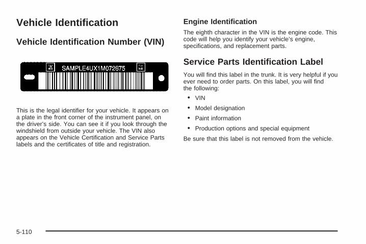
Vehicle Identification
Vehicle Identification Number (VIN)
This is the legal identifier for your vehicle. It appears ona plate in the front corner of the instrument panel, onthe driver’s side. You can see it if you look through thewindshield from outside your vehicle. The VIN alsoappears on the Vehicle Certification and Service Partslabels and the certificates of title and registration.
Engine IdentificationThe eighth character in the VIN is the engine code. Thiscode will help you identify your vehicle’s engine,specifications, and replacement parts.
Service Parts Identification LabelYou will find this label in the trunk. It is very helpful if youever need to order parts. On this label, you will findthe following:
• VIN
• Model designation
• Paint information
• Production options and special equipment
Be sure that this label is not removed from the vehicle.
5-110

Electrical System
Add-On Electrical EquipmentNotice: Don’t add anything electrical to your vehicleunless you check with your dealer first. Someelectrical equipment can damage your vehicle andthe damage wouldn’t be covered by your warranty.Some add-on electrical equipment can keep othercomponents from working as they should.
Your vehicle has an airbag system. Before attempting toadd anything electrical to your vehicle, see ServicingYour Airbag-Equipped Vehicle on page 1-65.
Headlamp WiringThe headlamp circuit is protected by individual fuses inthe underhood fuse block. An electrical overload willcause the fuse to blow. If this happens, have theheadlamp system checked right away.
Windshield Wiper FusesThe windshield wiper motor is protected by a circuitbreaker and a fuse. If the motor overheats due to heavysnow, etc., the wiper will stop until the motor cools. Ifthe overload is caused by some electrical problem, haveit fixed.
Power Windows and Other PowerOptionsCircuit breakers in the fuse panel protect the powerwindows and other power accessories. When the currentload is too heavy, the circuit breaker opens andcloses, protecting the circuit until the problem is fixed.
5-111

Fuses and Circuit BreakersThe wiring circuits in the vehicle are protected fromshort circuits by a combination of fuses, circuit breakersand fusible thermal links in the wiring itself. Thisgreatly reduces the chance of fires caused by electricalproblems.
Look at the silver-colored band inside the fuse. If theband is broken or melted, replace the fuse. Be sure toreplace a bad fuse with a new one of the identicalsize and rating. Spare fuses and a fuse puller arelocated in the underhood fuse block. See UnderhoodFuse Block later in this section.
Instrument Panel Fuse Block
Some fuses are in a fuseblock located on the endof the instrument panel onthe passenger side.
To get to the fuse block lift up on the side panel. A fuseusage chart is on the inside of this panel.
5-112

Fuse UsageRAP Retained Accessory Power
SUN ROOF SunroofCRUISE SW Cruise Switch
PK LP Parking LampsRR DEFOG Rear Window Defogger
DR LK/TRUNK Door Lock/TrunkONSTAR/ALDL Onstar®/Diagnostic Link
Fuse UsageCANISTER Fuel Tank Solenoid CanisterPK LAMPS Parking LampsRADIO/AMP Radio Amplifier
RFA/MOD Remote Function Activator (RemoteKeyless Entry)
DISPLAYSInstrument Panel Displays/Head-UpDisplay (HUD), Driver InformationCenter (DIC)
INT LIGHT Interior LampsHVAC Climate Controls
CHMSL/BKUP Center High Mounted StopLamp/Back-Up Lamps
PWR WDO Power WindowsSPRINGCOIL 2 Steering Wheel Control Switches
PWR SEAT Power Seat
TURN/HAZ Turn Signals/HazardWarning Lamps
PWR MIRS Power MirrorsHTD SEAT Heated Seat
To reinstall the end panel, position the lower sectionwith the edge of the instrument panel, and pressthe sides of the panel until it snaps into place.
5-113
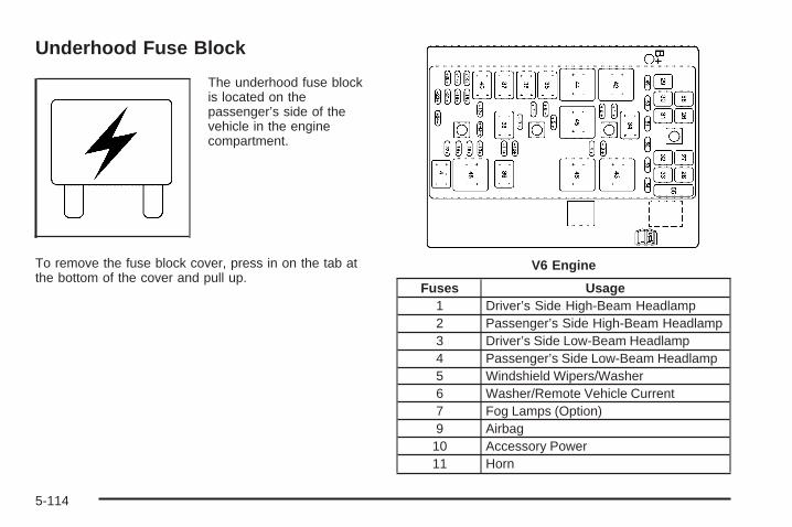
Underhood Fuse Block
The underhood fuse blockis located on thepassenger’s side of thevehicle in the enginecompartment.
To remove the fuse block cover, press in on the tab atthe bottom of the cover and pull up.
Fuses Usage1 Driver’s Side High-Beam Headlamp2 Passenger’s Side High-Beam Headlamp3 Driver’s Side Low-Beam Headlamp4 Passenger’s Side Low-Beam Headlamp5 Windshield Wipers/Washer6 Washer/Remote Vehicle Current7 Fog Lamps (Option)9 Airbag
10 Accessory Power11 Horn
V6 Engine
5-114

Fuses Usage12 Emission13 Air Conditioning Clutch14 Oxygen Sensor15 Powertrain Control Module
16 Powertrain Control Module/ElectronicThrottle Control
17 Electronic Throttle Control18 Display19 Anti-lock Brake Solenoid20 Fuel Injection21 Transmission Solenoid22 Fuel Pump23 Anti-lock Brakes24 Electronic Ignition26 Battery Main 127 Battery Main 228 Battery Main 329 Fan 130 Battery Main 431 Anti-lock Brake Motor32 Fan 233 Starter56 Air Pump
Relays Usage34 High-Beam Headlamps35 Low-Beam Headlamps36 Fog Lamps (Option)37 Ignition 138 Air Conditioner Compressor39 Horn40 Powertrain41 Fuel Pump42 Fan 143 Fan 344 Windshield Wiper/High45 Windshield Wiper46 Fan 248 Crank49 Spare Fuse50 Spare Fuse51 Spare Fuse52 Blank53 Blank54 Blank55 Fuse Puller
§ Air Conditioning Clutch
5-115
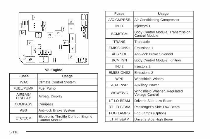
Fuses Usage
HVAC Climate Control System
FUEL/PUMP Fuel Pump
AIRBAG/DISPLAY Airbag, Display
COMPASS Compass
ABS Anti-lock Brake System
ETC/ECM Electronic Throttle Control, EngineControl Module
Fuses Usage
A/C CMPRSR Air Conditioning Compressor
INJ 1 Injectors 1
BCM/TCM Body Control Module, TransmissionControl Module
TRANS Transaxle
EMISSIONS1 Emissions 1
ABS SOL Anti-lock Brake Solenoid
BCM IGN Body Control Module, Ignition
INJ 2 Injectors 2
EMISSIONS2 Emissions 2
WPR Windshield Wipers
AUX PWR Auxiliary Power
WSW/RVC Windshield Washer, RegulatedVoltage Control
LT LO BEAM Driver’s Side Low Beam
RT LO BEAM Passenger’s Side Low Beam
FOG LAMPS Fog Lamps (Option)
LT HI BEAM Driver’s Side High Beam
V8 Engine
5-116

Fuses Usage
HORN Horn
RT HI BEAM Passenger’s Side High Beam
SPARE Spare
SPARE Spare
SPARE Spare
SPARE Spare
Relays Usage
BATT 4 Battery 4
FUEL/PUMP Fuel Pump
BATT 1 Battery 1
A/C CMPRSR Air Conditioning Compressor
Relays Usage
STRTR Starter
PWR/TRN Powertrain
STRTR Starter
ABS MTR Anti-lock Brake System Motor
BATT 3 Battery 3
BATT 2 Battery 2
FAN 2 Cooling Fan 2
FAN 3 Cooling Fan 3
FAN 2 Cooling Fan 2
FAN 1 Cooling Fan 1
FAN 1 Cooling Fan 1
5-117
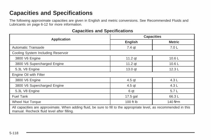
Capacities and SpecificationsThe following approximate capacities are given in English and metric conversions. See Recommended Fluids andLubricants on page 6-12 for more information.
Capacities and Specifications
ApplicationCapacities
English Metric
Automatic Transaxle 7.4 qt 7.0 L
Cooling System Including Reservoir
3800 V6 Engine 11.2 qt 10.6 L
3800 V6 Supercharged Engine 11.2 qt 10.6 L
5.3L V8 Engine 13.0 qt 12.3 L
Engine Oil with Filter
3800 V6 Engine 4.5 qt 4.3 L
3800 V6 Supercharged Engine 4.5 qt 4.3 L
5.3L V8 Engine 6 qt 5.7 L
Fuel Tank 17.5 gal 66.3 L
Wheel Nut Torque 100 ft lb 140 Y
All capacities are approximate. When adding fluid, be sure to fill to the appropriate level, as recommended in thismanual. Recheck fluid level after filling.
5-118
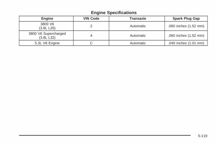
Engine SpecificationsEngine VIN Code Transaxle Spark Plug Gap
3800 V6(3.8L L26) 2 Automatic .060 inches (1.52 mm)
3800 V6 Supercharged(3.8L L32) 4 Automatic .060 inches (1.52 mm)
5.3L V8 Engine C Automatic .040 inches (1.01 mm)
5-119

✍ NOTES
5-120

Maintenance Schedule ......................................6-2Introduction ...................................................6-2Maintenance Requirements ..............................6-2Your Vehicle and the Environment ....................6-2Using the Maintenance Schedule ......................6-2Scheduled Maintenance ...................................6-4Additional Required Services ............................6-6Maintenance Footnotes ...................................6-7
Owner Checks and Services ............................6-8At Each Fuel Fill ............................................6-9At Least Once a Month ...................................6-9At Least Once a Year ...................................6-10Recommended Fluids and Lubricants ...............6-12Normal Maintenance Replacement Parts ..........6-13Maintenance Record .....................................6-14
Section 6 Maintenance Schedule
6-1
Maintenance Schedule
IntroductionImportant: Keep engine oil at the proper level andchange as recommended.
Have you purchased the GM Protection Plan? The Plansupplements your new vehicle warranties. See yourWarranty and Owner Assistance booklet or your dealerfor details.
Maintenance RequirementsNotice: Maintenance intervals, checks, inspections,replacement parts, and recommended fluids andlubricants as prescribed in this manual are necessaryto keep your vehicle in good working condition. Anydamage caused by failure to follow scheduledmaintenance may not be covered by warranty.
Your Vehicle and the EnvironmentProper vehicle maintenance not only helps to keep yourvehicle in good working condition, but also helps theenvironment. All recommended maintenance isimportant. Improper vehicle maintenance can evenaffect the quality of the air we breathe. Improper fluidlevels or the wrong tire inflation can increase the level ofemissions from your vehicle. To help protect ourenvironment, and to keep your vehicle in good condition,be sure to maintain your vehicle properly.
Using the Maintenance ScheduleWe at General Motors want to help you keep yourvehicle in good working condition. But we do not knowexactly how you will drive it. You may drive veryshort distances only a few times a week. Or you maydrive long distances all the time in very hot, dustyweather. You may use your vehicle in making deliveries.Or you may drive it to work, to do errands, or in manyother ways.
Because of all the different ways people use theirvehicles, maintenance needs vary. You may need morefrequent checks and replacements. So please readthe following and note how you drive. If you have anyquestions on how to keep your vehicle in good condition,see your GM Goodwrench® dealer.
6-2

This schedule is for vehicles that:
• carry passengers and cargo within recommendedlimits. You will find these limits on the tire andloading information label. See Loading Your Vehicleon page 4-33.
• are driven on reasonable road surfaces within legaldriving limits.
• use the recommended fuel. See Gasoline Octaneon page 5-5.
The services in Scheduled Maintenance on page 6-4should be performed when indicated. See AdditionalRequired Services on page 6-6 and MaintenanceFootnotes on page 6-7 for further information.
{CAUTION:
Performing maintenance work on a vehicle canbe dangerous. In trying to do some jobs, youcan be seriously injured. Do your ownmaintenance work only if you have therequired know-how and the proper tools andequipment for the job. If you have any doubt,see your GM Goodwrench ® dealer to have aqualified technician do the work.
Some maintenance services can be complex. So,unless you are technically qualified and have thenecessary equipment, you should have yourGM Goodwrench® dealer do these jobs.
When you go to your GM Goodwrench® dealer for yourservice needs, you will know that GM-trained andsupported service technicians will perform the workusing genuine GM parts.
If you want to purchase service information, see ServicePublications Ordering Information on page 7-14.
Owner Checks and Services on page 6-8 tells you whatshould be checked, when to check it, and what youcan easily do to help keep your vehicle in goodcondition.
The proper replacement parts, fluids, and lubricants touse are listed in Recommended Fluids and Lubricantson page 6-12 and Normal Maintenance ReplacementParts on page 6-13. When your vehicle is serviced,make sure these are used. All parts should be replacedand all necessary repairs done before you or anyoneelse drives the vehicle. We recommend the use ofgenuine GM parts.
6-3

Scheduled MaintenanceWhen the CHANGE OIL SOON message comes on, itmeans that service is required for your vehicle. SeeDIC Warnings and Messages on page 3-72. Have yourvehicle serviced as soon as possible within the next600 miles (1 000 km). It is possible that, if you aredriving under the best conditions, the engine oil lifesystem may not indicate that vehicle service isnecessary for over a year. However, your engine oiland filter must be changed at least once a year andat this time the system must be reset. YourGM Goodwrench® dealer has GM-trained servicetechnicians who will perform this work using genuineGM parts and reset the system.
If the engine oil life system is ever reset accidentally,you must service your vehicle within 3,000 miles(5 000 km) since your last service. Remember to resetthe oil life system whenever the oil is changed. SeeEngine Oil Life System on page 5-19 for information onthe Engine Oil Life System and resetting the system.
When the CHANGE OIL SOON message appears,certain services, checks, and inspections are required.Required services are described in the following for“Maintenance I” and “Maintenance II.” Generally,it is recommended that your first service beMaintenance I, your second service be Maintenance II,and that you alternate Maintenance I and Maintenance IIthereafter. However, in some cases, Maintenance IImay be required more often.
Maintenance I — Use Maintenance I if the CHANGEOIL SOON message comes on within 10 monthssince the vehicle was purchased or Maintenance IIwas performed.
Maintenance II — Use Maintenance II if the previousservice performed was Maintenance I. Always useMaintenance II whenever the message comes on10 months or more since the last service or if themessage has not come on at all for one year.
6-4
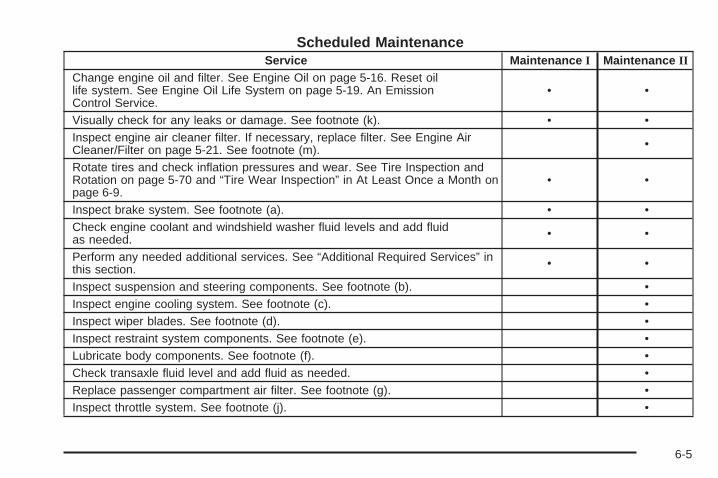
Scheduled MaintenanceService Maintenance I Maintenance II
Change engine oil and filter. See Engine Oil on page 5-16. Reset oillife system. See Engine Oil Life System on page 5-19. An EmissionControl Service.
• •
Visually check for any leaks or damage. See footnote (k). • •Inspect engine air cleaner filter. If necessary, replace filter. See Engine AirCleaner/Filter on page 5-21. See footnote (m). •
Rotate tires and check inflation pressures and wear. See Tire Inspection andRotation on page 5-70 and “Tire Wear Inspection” in At Least Once a Month onpage 6-9.
• •
Inspect brake system. See footnote (a). • •Check engine coolant and windshield washer fluid levels and add fluidas needed. • •
Perform any needed additional services. See “Additional Required Services” inthis section. • •
Inspect suspension and steering components. See footnote (b). •Inspect engine cooling system. See footnote (c). •Inspect wiper blades. See footnote (d). •Inspect restraint system components. See footnote (e). •Lubricate body components. See footnote (f). •Check transaxle fluid level and add fluid as needed. •Replace passenger compartment air filter. See footnote (g). •Inspect throttle system. See footnote (j). •
6-5

Additional Required ServicesThe following services should be performed at the first maintenance service (I or II) after the indicated miles(kilometers) shown for each item.
Additional Required Services
Service and Miles (Kilometers) 25,000(41 500)
50,000(83 000)
75,000(125 000)
100,000(166 000)
125,000(207 500)
150,000(240 000)
Inspect fuel system for damage or leaks. • • • • • •Inspect exhaust system for loose ordamaged components. • • • • • •
Replace engine air cleaner filter. SeeEngine Air Cleaner/Filter on page 5-21. • • •
Supercharger service, if equipped.An Emission Control Service. Seefootnotes † and (l).
• • • • • •
Change automatic transaxle fluid andfilter (severe service). See footnote (h). • • •
Change automatic transaxle fluid andfilter (normal service). •
Replace spark plugs and inspect sparkplug wires. An Emission Control Service. •
Engine cooling system service(or every five years, whichever occursfirst). An Emission Control Service. Seefootnote (i).
•
Inspect engine accessory drive belt.An Emission Control Service. Seefootnote (n).
•
6-6
Maintenance Footnotes† The U.S. Environmental Protection Agency or theCalifornia Air Resources Board has determined that thefailure to perform this maintenance item will not nullifythe emission warranty or limit recall liability prior tothe completion of the vehicle’s useful life. We, however,urge that all recommended maintenance services beperformed at the indicated intervals and themaintenance be recorded.
(a) Visually inspect brake lines and hoses for properhook-up, binding, leaks, cracks, chafing, etc. Inspectdisc brake pads for wear and rotors for surfacecondition. Inspect other brake parts, including calipers,parking brake, etc.
(b) Visually inspect front and rear suspension andsteering system for damaged, loose, or missing parts orsigns of wear. Inspect power steering lines and hosesfor proper hook-up, binding, leaks, cracks, chafing, etc.
(c) Visually inspect hoses and have them replaced ifthey are cracked, swollen, or deteriorated. Inspectall pipes, fittings, and clamps; replace with genuineGM parts as needed. To help ensure proper operation,a pressure test of the cooling system and pressurecap and cleaning the outside of the radiator andair conditioning condenser is recommended at leastonce a year.
(d) Visually inspect wiper blades for wear or cracking.Replace wiper blades that appear worn or damagedor that streak or miss areas of the windshield.
(e) Make sure the safety belt reminder light and allbelts, buckles, latch plates, retractors, and anchoragesare working properly. Look for any other loose ordamaged safety belt system parts. If you see anythingthat might keep a safety belt system from doing itsjob, have it repaired. Have any torn or frayed safety beltsreplaced. Also look for any opened or broken airbagcoverings, and have them repaired or replaced.The airbag system does not need regular maintenance.
(f) Lubricate all key lock cylinders. Lubricate allhinges and latches, including those for the body doors,hood, secondary latch, pivots, spring anchor, releasepawl, rear compartment, glove box door, console door,and any folding seat hardware. More frequentlubrication may be required when exposed to a corrosiveenvironment. Applying silicone grease on weatherstripswith a clean cloth will make them last longer, sealbetter, and not stick or squeak.
(g) If you drive regularly under dusty conditions, thefilter may require replacement more often.
6-7
(h) Change automatic transaxle fluid and filter ifthe vehicle is mainly driven under one or more of theseconditions:
− In heavy city traffic where the outside temperatureregularly reaches 90°F (32°C) or higher.
− In hilly or mountainous terrain.− When doing frequent trailer towing.− Uses such as found in taxi, police, or delivery
service.
(i) Drain, flush, and refill cooling system. This servicecan be complex; you should have your dealer performthis service. See Engine Coolant on page 5-25 forwhat to use. Inspect hoses. Clean radiator, condenser,pressure cap, and filler neck. Pressure test thecooling system and pressure cap.
(j) Check throttle system for interference or binding andfor damaged or missing parts. Replace parts asneeded. Replace any components that have high effortor excessive wear. Do not lubricate accelerator orcruise control cables.
(k) A fluid loss in any vehicle system could indicate aproblem. Have the system inspected and repairedand the fluid level checked. Add fluid if needed.
(l) For supercharged engines only: Have your dealercheck the supercharger oil level and add the propersupercharger oil as needed (or every 36 months,whichever occurs first). See Recommended Fluidsand Lubricants on page 6-12.
(m) If you drive regularly under dusty conditions, inspectthe filter at each engine oil change.
(n) Visually inspect belt for fraying, excessive cracks, orobvious damage. Replace belt if necessary.
Owner Checks and ServicesThese owner checks and services should be performedat the intervals specified to help ensure the safety,dependability, and emission control performance of yourvehicle. Your GM Goodwrench® dealer can assist youwith these checks and services.
Be sure any necessary repairs are completed at once.Whenever any fluids or lubricants are added to yourvehicle, make sure they are the proper ones, as shownin Recommended Fluids and Lubricants on page 6-12.
6-8
At Each Fuel FillIt is important to perform these underhood checks ateach fuel fill.
Engine Oil Level CheckCheck the engine oil level and add the proper oilif necessary. See Engine Oil on page 5-16 forfurther details.
Notice: It is important to check your oil regularlyand keep it at the proper level. Failure to keep yourengine oil at the proper level can cause damageto your engine not covered by your warranty.
Engine Coolant Level CheckCheck the engine coolant level and addDEX-COOL® coolant mixture if necessary. See EngineCoolant on page 5-25 for further details.
Windshield Washer Fluid Level CheckCheck the windshield washer fluid level in the windshieldwasher fluid reservoir and add the proper fluid ifnecessary.
At Least Once a Month
Tire Inflation CheckVisually inspect your vehicle’s tires and make sure theyare inflated to the correct pressures. Do not forget tocheck the spare tire. See Tires on page 5-60 for furtherdetails. Check to make sure the spare tire is storedsecurely. See Changing a Flat Tire on page 5-88.
Tire Wear InspectionTire rotation may be required for high mileage highwaydrivers prior to the Engine Oil Life System servicenotification. Check the tires for wear and, if necessary,rotate the tires. See Tire Inspection and Rotation onpage 5-70.
6-9

At Least Once a Year
Starter Switch Check
{CAUTION:
When you are doing this inspection, thevehicle could move suddenly. If the vehiclemoves, you or others could be injured.
1. Before you start, be sure you have enough roomaround the vehicle.
2. Firmly apply both the parking brake and the regularbrake. See Parking Brake on page 2-30.Do not use the accelerator pedal, and be ready toturn off the engine immediately if it starts.
3. Try to start the engine in each gear. The vehicleshould start only in PARK (P) or NEUTRAL (N). Ifthe vehicle starts in any other position, contact yourGM Goodwrench® dealer for service.
Automatic Transaxle Shift Lock ControlSystem Check
{CAUTION:
When you are doing this inspection, thevehicle could move suddenly. If the vehiclemoves, you or others could be injured.
1. Before you start, be sure you have enough roomaround the vehicle. It should be parked on a levelsurface.
2. Firmly apply the parking brake. See Parking Brakeon page 2-30.Be ready to apply the regular brake immediately ifthe vehicle begins to move.
3. With the engine off, turn the ignition to RUN, but donot start the engine. Without applying the regularbrake, try to move the shift lever out of PARK (P)with normal effort. If the shift lever moves outof PARK (P), contact your GM Goodwrench® dealerfor service.
6-10

Ignition Transaxle Lock CheckWhile parked, and with the parking brake set, try to turnthe ignition to OFF in each shift lever position.
• The ignition should turn to OFF only when the shiftlever is in PARK (P).
• The key should come out only in OFF.
Contact your GM Goodwrench® dealer if service isrequired.
Parking Brake and Automatic TransaxlePark (P) Mechanism Check
{CAUTION:
When you are doing this check, your vehiclecould begin to move. You or others could beinjured and property could be damaged. Makesure there is room in front of your vehicle incase it begins to roll. Be ready to apply theregular brake at once should the vehicle beginto move.
Park on a fairly steep hill, with the vehicle facingdownhill. Keeping your foot on the regular brake, set theparking brake.
• To check the parking brake’s holding ability: Withthe engine running and transaxle in NEUTRAL (N),slowly remove foot pressure from the regularbrake pedal. Do this until the vehicle is held by theparking brake only.
• To check the PARK (P) mechanism’s holdingability: With the engine running, shift to PARK (P).Then release the parking brake followed by theregular brake.
Contact your GM Goodwrench® dealer if service isrequired.
Underbody Flushing ServiceAt least every spring, use plain water to flush anycorrosive materials from the underbody. Take care toclean thoroughly any areas where mud and other debriscan collect.
6-11
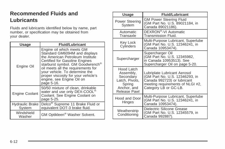
Recommended Fluids andLubricantsFluids and lubricants identified below by name, partnumber, or specification may be obtained fromyour dealer.
Usage Fluid/Lubricant
Engine Oil
Engine oil which meets GMStandard GM6094M and displaysthe American Petroleum InstituteCertified for Gasoline Enginesstarburst symbol. GM Goodwrench®
oil meets all the requirements foryour vehicle. To determine theproper viscosity for your vehicle’sengine, see Engine Oil onpage 5-16.
Engine Coolant
50/50 mixture of clean, drinkablewater and use only DEX-COOL®
Coolant. See Engine Coolant onpage 5-25.
Hydraulic BrakeSystem
Delco® Supreme 11 Brake Fluid orequivalent DOT-3 brake fluid.
WindshieldWasher GM Optikleen® Washer Solvent.
Usage Fluid/Lubricant
Power SteeringSystem
GM Power Steering Fluid(GM Part No. U.S. 89021184, inCanada 89021186).
AutomaticTransaxle
DEXRON®-VI AutomaticTransmission Fluid.
Key LockCylinders
Multi-Purpose Lubricant, Superlube(GM Part No. U.S. 12346241, inCanada 10953474).
Supercharger
Supercharger Oil(GM Part No. U.S. 12345982,in Canada 10953513). SeeSupercharger Oil on page 5-20.
Hood LatchAssembly,Secondary
Latch, Pivots,Spring
Anchor, andRelease Pawl
Lubriplate Lubricant Aerosol(GM Part No. U.S. 12346293, inCanada 992723) or lubricantmeeting requirements of NLGI #2,Category LB or GC-LB.
Hood and DoorHinges
Multi-Purpose Lubricant, Superlube(GM Part No. U.S. 12346241, inCanada 10953474).
WeatherstripConditioning
Dielectric Silicone Grease(GM Part No. U.S. 12345579, inCanada 992887).
6-12
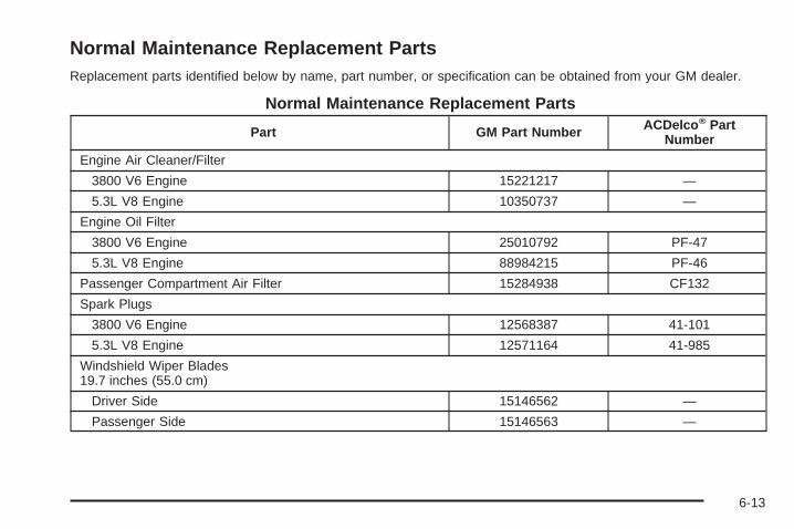
Normal Maintenance Replacement PartsReplacement parts identified below by name, part number, or specification can be obtained from your GM dealer.
Normal Maintenance Replacement Parts
Part GM Part Number ACDelco ® PartNumber
Engine Air Cleaner/Filter
3800 V6 Engine 15221217 —
5.3L V8 Engine 10350737 —
Engine Oil Filter
3800 V6 Engine 25010792 PF-47
5.3L V8 Engine 88984215 PF-46
Passenger Compartment Air Filter 15284938 CF132
Spark Plugs
3800 V6 Engine 12568387 41-101
5.3L V8 Engine 12571164 41-985
Windshield Wiper Blades19.7 inches (55.0 cm)
Driver Side 15146562 —
Passenger Side 15146563 —
6-13
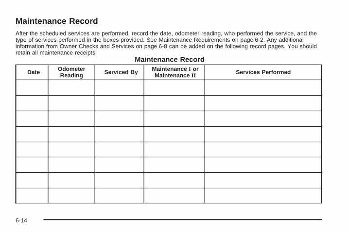
Maintenance RecordAfter the scheduled services are performed, record the date, odometer reading, who performed the service, and thetype of services performed in the boxes provided. See Maintenance Requirements on page 6-2. Any additionalinformation from Owner Checks and Services on page 6-8 can be added on the following record pages. You shouldretain all maintenance receipts.
Maintenance Record
Date OdometerReading Serviced By Maintenance I or
Maintenance II Services Performed
6-14
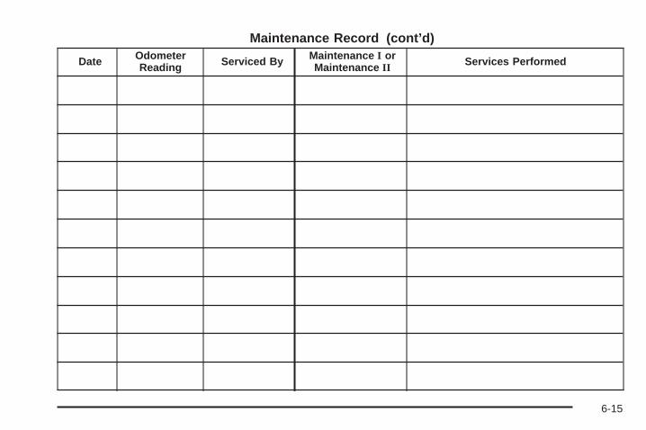
Maintenance Record (cont’d)
Date OdometerReading Serviced By Maintenance I or
Maintenance II Services Performed
6-15
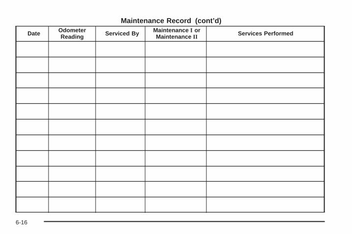
Maintenance Record (cont’d)
Date OdometerReading Serviced By Maintenance I or
Maintenance II Services Performed
6-16

Customer Assistance and Information ...............7-2Customer Satisfaction Procedure ......................7-2Online Owner Center ......................................7-3Customer Assistance for Text Telephone
(TTY) Users ...............................................7-4Customer Assistance Offices ............................7-4GM Mobility Reimbursement Program ................7-5Roadside Assistance Program ..........................7-6Courtesy Transportation ...................................7-7Vehicle Data Collection and Event Data
Recorders ..................................................7-9Collision Damage Repair ................................7-10
Reporting Safety Defects ................................7-13Reporting Safety Defects to the United
States Government ....................................7-13Reporting Safety Defects to the Canadian
Government ..............................................7-14Reporting Safety Defects to General Motors .....7-14Service Publications Ordering Information .........7-14
Section 7 Customer Assistance and Information
7-1

Customer Assistance andInformation
Customer Satisfaction ProcedureYour satisfaction and goodwill are important toyour dealer and to Pontiac. Normally, any concerns withthe sales transaction or the operation of your vehiclewill be resolved by your dealer’s sales or servicedepartments. Sometimes, however, despite the bestintentions of all concerned, misunderstandings canoccur. If your concern has not been resolved to yoursatisfaction, the following steps should be taken:
STEP ONE: Discuss your concern with a member ofdealership management. Normally, concerns canbe quickly resolved at that level. If the matter hasalready been reviewed with the sales, service or partsmanager, contact the owner of the dealership orthe general manager.
STEP TWO: If after contacting a member of dealershipmanagement, it appears your concern cannot beresolved by the dealership without further help, contactthe Pontiac Customer Assistance Center by calling1-800-762-2737. In Canada, contact GM of CanadaCustomer Communication Centre in Oshawa by calling1-800-263-3777 (English) or 1-800-263-7854 (French).
We encourage you to call the toll-free number in orderto give your inquiry prompt attention. Please havethe following information available to give the CustomerAssistance Representative:
• Vehicle Identification Number (VIN). This isavailable from the vehicle registration or title, or theplate at the top left of the instrument panel andvisible through the windshield.
• Dealership name and location.
• Vehicle delivery date and present mileage.
When contacting Pontiac, please remember that yourconcern will likely be resolved at a dealer’s facility. Thatis why we suggest you follow Step One first if youhave a concern.
STEP THREE: Both General Motors and your dealerare committed to making sure you are completelysatisfied with your new vehicle. However, if you continueto remain unsatisfied after following the procedureoutlined in Steps One and Two, you should file with theBBB Auto Line Program to enforce any additionalrights you may have. Canadian owners refer to yourWarranty and Owner Assistance Information booklet forinformation on the Canadian Motor Vehicle ArbitrationPlan (CAMVAP).
7-2
The BBB Auto Line Program is an out of court programadministered by the Council of Better BusinessBureaus to settle automotive disputes regarding vehiclerepairs or the interpretation of the New VehicleLimited Warranty. Although you may be required toresort to this informal dispute resolution program prior tofiling a court action, use of the program is free ofcharge and your case will generally be heard within40 days. If you do not agree with the decision given inyour case, you may reject it and proceed with any othervenue for relief available to you.
You may contact the BBB Auto Line Program using thetoll-free telephone number or write them at thefollowing address:
BBB Auto Line ProgramCouncil of Better Business Bureaus, Inc.4200 Wilson BoulevardSuite 800Arlington, VA 22203-1838
Telephone: 1-800-955-5100
This program is available in all 50 states and the Districtof Columbia. Eligibility is limited by vehicle age,mileage and other factors. General Motors reserves theright to change eligibility limitations and/or discontinueits participation in this program.
Online Owner CenterThe Owner Center is a resource for your GM ownershipneeds. Specific vehicle information can be found inone place.
The Online Owner Center allows you to:
• Get e-mail service reminders.
• Access information about your specific vehicle,including tips and videos and an electronicversion of this owner’s manual (United States only).
• Keep track of your vehicle’s service history andmaintenance schedule.
• Find GM dealers for service nationwide.
• Receive special promotions and privileges onlyavailable to members (United States only).
Refer to the web for updated information.
To register your vehicle, visit www.MyGMLink.com(United States) or My GM Canada withinwww.gmcanada.com (Canada).
7-3

Customer Assistance for TextTelephone (TTY) UsersTo assist customers who are deaf, hard of hearing, orspeech-impaired and who use Text Telephones (TTYs),Pontiac has TTY equipment available at its CustomerAssistance Center. Any TTY user can communicatewith Pontiac by dialing: 1-800-833-PONT (7668).(TTY users in Canada can dial 1-800-263-3830.)
Customer Assistance OfficesPontiac encourages customers to call the toll-freenumber for assistance. However, if a customer wishesto write or e-mail Pontiac, refer to the addresses below.
United States — Customer AssistancePontiac Customer Assistance CenterP.O. Box 33172Detroit, MI 48232-5172
www.Pontiac.com1-800-762-2737 or1-800-833-7668 (For Text Telephone devices (TTYs))Roadside Assistance: 1-800-ROADSIDE (762-3743)Fax Number: 313-381-0022
From Puerto Rico:1-800-496-9992 (English)1-800-496-9993 (Spanish)Fax Number: 313-381-0022
From U.S. Virgin Islands:1-800-496-9994Fax Number: 313-381-0022
Canada — Customer AssistanceGeneral Motors of Canada LimitedCustomer Communication Centre, 163-0051908 Colonel Sam DriveOshawa, Ontario L1H 8P7
1-800-263-3777 (English)1-800-263-7854 (French)1-800-263-3830 (For Text Telephone devices (TTYs))Roadside Assistance: 1-800-268-6800
7-4

Overseas — Customer AssistancePlease contact the local General Motors Business Unit.
Mexico, Central America andCaribbean Islands/Countries(Except Puerto Rico and U.S. VirginIslands) — Customer Assistance
General Motors de Mexico, S. de R.L. de C.V.Customer Assistance CenterPaseo de la Reforma #2740Col. Lomas de BezaresC.P. 11910, Mexico, D.F.01-800-508-0000Long Distance: 011-52-53 29 0 800
GM Mobility ReimbursementProgram
This program, available to qualified applicants, canreimburse you up to $1,000 of the cost of eligibleaftermarket adaptive equipment required for your vehicle,such as hand controls or a wheelchair/scooter lift.
The offer is available for a very limited period of timefrom the date of vehicle purchase/lease. For moredetails, or to determine your vehicle’s eligibility, visitgmmobility.com or call the GM Mobility AssistanceCenter at 1-800-323-9935. Text telephone (TTY) users,call 1-800-833-9935.
GM of Canada also has a Mobility Program. Call1-800-GM-DRIVE (463-7483) for details. TTY users call1-800-263-3830.
7-5

Roadside Assistance ProgramAs the owner of a new Pontiac vehicle, you areautomatically enrolled in the Pontiac RoadsideAssistance program. This value-added service isintended to provide you with peace of mind as you drivein the city or travel the open road. Contact Pontiac’sRoadside Assistance toll-free at 1-800-ROADSIDE(762-3743). Roadside Assistance Representatives areavailable 24 hours a day, 365 days a year.
We will provide the following services during theBumper-to-Bumper warranty period, at no expenseto you:
• Fuel Delivery: Delivery of enough fuel($5 maximum) for the customer to get to thenearest service station.
• Lock-out Service (identification required):Replacement keys or locksmith service willbe covered at no charge if you are unable to gainentry into your vehicle. Delivery of the replacementkey will be covered within 10 miles (16 km).
• Emergency Tow: Tow to the nearest dealership forwarranty service or in the event of avehicle-disabling accident. Assistance providedwhen the vehicle is mired in sand, mud, or snow.
• Flat Tire Change: Installation of a spare tire will becovered at no charge. The customer is responsiblefor the repair or replacement of the tire if notcovered by a warrantable failure.
• Jump Start: No-start occurrences which require abattery jump start will be covered at no charge.
• Dealer Locator Service
In many instances, mechanical failures are coveredunder Pontiac’s Bumper-to-Bumper warranty. However,when other services are utilized, our RoadsideAssistance Representatives will explain any paymentobligations you might incur.
For prompt and efficient assistance when calling,please provide the following to the RoadsideAssistance Representative:
• Your name, home address, and home telephonenumber.
• Telephone number of your location.
• Location of the vehicle.
• Model, year, color, and license plate number of thevehicle.
• Mileage, Vehicle Identification Number (VIN), anddelivery date of the vehicle.
• Description of the problem.
7-6

While we hope you never have the occasion to use ourservice, it is added security while traveling for youand your family. Remember, we are only a phone callaway. Pontiac Roadside Assistance: 1-800-ROADSIDE(762-3743), text telephone (TTY) users, call1-888-889-2438.
Pontiac reserves the right to limit services orreimbursement to an owner or driver when, in Pontiac’sjudgement, the claims become excessive in frequencyor type of occurrence.
Roadside Assistance is not part of or included in thecoverage provided by the New Vehicle Limited Warranty.Pontiac reserves the right to make any changes ordiscontinue the Roadside Assistance program at anytime without notification.
Canadian Roadside AssistanceVehicles purchased in Canada have an extensiveroadside assistance program accessible from anywherein Canada or the United States. Please refer to theWarranty and Owner Assistance Information book.
Courtesy TransportationTo enhance your ownership experience, we and ourparticipating dealers are proud to offer CourtesyTransportation, a customer support program fornew vehicles.
The Courtesy Transportation program is offered tocustomers in conjunction with the Bumper-to-Bumpercoverage provided by the New Vehicle Limited Warranty.Several transportation options are available whenwarranty repairs are required. This will reduce yourinconvenience during warranty repairs.
Scheduling Service AppointmentsWhen your vehicle requires warranty service, you shouldcontact your dealer and request an appointment. Byscheduling a service appointment and advisingyour service consultant of your transportation needs,your dealer can help minimize your inconvenience.
If your vehicle cannot be scheduled into the servicedepartment immediately, keep driving it until it can bescheduled for service, unless, of course, the problem issafety-related. If it is, please call your dealership, letthem know this, and ask for instructions.
If the dealer requests that you simply drop the vehicle offfor service, you are urged to do so as early in the workday as possible to allow for the same day repair.
7-7
Transportation OptionsWarranty service can generally be completed while youwait. However, if you are unable to wait, GM helpsto minimize your inconvenience by providing severaltransportation options. Depending on the circumstances,your dealer can offer you one of the following:
Shuttle ServiceParticipating dealers can provide you with shuttleservice to get you to your destination with minimalinterruption of your daily schedule. This includesone-way or round trip shuttle service to a destination upto 10 miles (16 km) from the dealership.
Public Transportation or FuelReimbursementIf your vehicle requires overnight warranty repairs,reimbursement of public transportation expenses maybe available, for up to a maximum of five days. Inaddition, should you arrange transportation through afriend or relative, reimbursement for reasonablefuel expenses may be available, up to a five-daymaximum. Claim amounts should reflect actual costsand be supported by original receipts.
Courtesy Rental VehicleYour dealer may arrange to provide you with a courtesyrental vehicle or reimburse you for a rental vehiclethat you obtain if your vehicle is kept for a warrantyrepair. Reimbursement will be limited to a maximumamount per day and must be supported by receipts. Thisrequires that you sign and complete a rental agreementand meet state, local and rental vehicle providerrequirements. Requirements vary and may includeminimum age requirements, insurance coverage, creditcard, etc. You are responsible for fuel usage chargesand may also be responsible for taxes, levies,usage fees, excessive mileage or rental usage beyondthe completion of the repair.
Generally it is not possible to provide a like-vehicle as acourtesy rental.
Additional Program InformationCourtesy Transportation is available during theBumper-to-Bumper warranty coverage period, but it isnot part of the New Vehicle Limited Warranty. Aseparate booklet entitled Warranty and OwnerAssistance Information furnished with each new vehicleprovides detailed warranty coverage information.
7-8

Courtesy Transportation is available only at participatingdealers and all program options, such as shuttleservice, may not be available at every dealer. Pleasecontact your dealer for specific information aboutavailability. All Courtesy Transportation arrangementswill be administered by appropriate dealer personnel.Canadian Vehicles: For warranty repairs duringthe Complete Vehicle Coverage period of the GeneralMotors of Canada New Vehicle Limited Warranty,alternative transportation may be available under theCourtesy Transportation Program. Please consultyour dealer for details.General Motors reserves the right to unilaterally modify,change or discontinue Courtesy Transportation atany time and to resolve all questions of claim eligibilitypursuant to the terms and conditions describedherein at its sole discretion.
Vehicle Data Collection and EventData RecordersYour vehicle, like other modern motor vehicles, has anumber of sophisticated computer systems that monitorand control several aspects of the vehicle’s performance.Your vehicle uses on-board vehicle computers to monitoremission control components to optimize fuel economy,to monitor conditions for airbag deployment and, if soequipped, to provide anti-lock braking and to help thedriver control the vehicle in difficult driving situations.
Some information may be stored during regularoperations to facilitate repair of detected malfunctions;other information is stored only in a crash event bycomputer systems, such as those commonly called eventdata recorders (EDR).
In a crash event, computer systems, such as the AirbagSensing and Diagnostic Module (SDM) in your vehiclemay record information about the condition of the vehicleand how it was operated, such as data related toengine speed, brake application, throttle position, vehiclespeed, safety belt usage, airbag readiness, airbagperformance, and the severity of a collision. If yourvehicle is equipped with StabiliTrak®, steeringperformance, including yaw rate, steering wheel angle,and lateral acceleration, is also recorded. Thisinformation has been used to improve vehicle crashperformance and may be used to improve crashperformance of future vehicles and driving safety. Unlikethe data recorders on many airplanes, these on-boardsystems do not record sounds, such as conversation ofvehicle occupants.
7-9

To read this information, special equipment is neededand access to the vehicle or the device that storesthe data is required. GM will not access informationabout a crash event or share it with others other than:• with the consent of the vehicle owner or, if the
vehicle is leased, with the consent of the lessee,• in response to an official request of police or similar
government office,• as part of GM’s defense of litigation through the
discovery process, or• as required by law.
In addition, once GM collects or receives data, GM may:• use the data for GM research needs,• make it available for research where appropriate
confidentiality is to be maintained and need isshown, or
• share summary data which is not tied to a specificvehicle with non-GM organizations for researchpurposes.
Others, such as law enforcement, may have access tothe special equipment that can read the informationif they have access to the vehicle or the devicethat stores the data.If your vehicle is equipped with OnStar®, please checkthe OnStar® subscription service agreement or manualfor information on its operations and data collection.
Collision Damage RepairIf your vehicle is involved in a collision and it isdamaged, have the damage repaired by a qualifiedtechnician using the proper equipment and qualityreplacement parts. Poorly performed collision repairswill diminish your vehicle’s resale value, and safetyperformance can be compromised in subsequentcollisions.
Collision PartsGenuine GM Collision parts are new parts made with thesame materials and construction methods as the partswith which your vehicle was originally built. GenuineGM Collision parts are your best choice to assure thatyour vehicle’s designed appearance, durability and safetyare preserved. The use of Genuine GM parts can helpmaintain your GM New Vehicle Warranty.
Recycled original equipment parts may also be used forrepair. These parts are typically removed from vehiclesthat were total losses in prior accidents. In mostcases, the parts being recycled are from undamagedsections of the vehicle. A recycled original equipmentGM part, may be an acceptable choice to maintain yourvehicle’s originally designed appearance and safetyperformance, however, the history of these parts is notknown. Such parts are not covered by your GM NewVehicle Limited Warranty, and any related failuresare not covered by that warranty.
7-10

Aftermarket collision parts are also available. These aremade by companies other than GM and may nothave been tested for your vehicle. As a result, theseparts may fit poorly, exhibit premature durability/corrosion problems, and may not perform properly insubsequent collisions. Aftermarket parts are not coveredby your GM New Vehicle Limited Warranty, and anyvehicle failure related to such parts are not covered bythat warranty.
Repair FacilityGM also recommends that you choose a collision repairfacility that meets your needs before you ever needcollision repairs. Your GM dealer may have a collisionrepair center with GM-trained technicians and stateof the art equipment, or be able to recommend acollision repair center that has GM-trained techniciansand comparable equipment.
Insuring Your VehicleProtect your investment in your GM vehicle withcomprehensive and collision insurance coverage. Thereare significant differences in the quality of coverageafforded by various insurance policy terms. Manyinsurance policies provide reduced protection to yourGM vehicle by limiting compensation for damage repairsby using aftermarket collision parts. Some insurancecompanies will not specify aftermarket collisionparts. When purchasing insurance, we recommend thatyou assure your vehicle will be repaired with GMoriginal equipment collision parts. If such insurancecoverage is not available from your current insurancecarrier, consider switching to another insurance carrier.
If your vehicle is leased, the leasing company mayrequire you to have insurance that assures repairs withGenuine GM Original Equipment Manufacturer (OEM)parts or Genuine Manufacturer replacement parts. Readyour lease carefully, as you may be charged at theend of your lease for poor quality repairs.
7-11
If an Accident OccursHere is what to do if you are involved in an accident.
• Try to relax and then check to make sure you are allright. If you are uninjured, make sure that no one elsein your vehicle, or the other vehicle, is injured.
• If there has been an injury, call 911 for help. Do notleave the scene of an accident until all matters havebeen taken care of. Move your vehicle only if itsposition puts you in danger or you are instructed tomove it by a police officer.
• Give only the necessary and requested informationto police and other parties involved in the accident.Do not discuss your personal condition, mental frameof mind, or anything unrelated to the accident. Thiswill help guard against post-accident legal action.
• If you need roadside assistance, call GM RoadsideAssistance. See Roadside Assistance Program onpage 7-6 for more information.
• If your vehicle cannot be driven, know where thetowing service will be taking it. Get a card from thetow truck operator or write down the driver’s name,the service’s name, and the phone number.
• Remove any valuables from your vehicle before it istowed away. Make sure this includes your insuranceinformation and registration if you keep these itemsin your vehicle.
• Gather the important information you will need fromthe other driver. Things like name, address, phonenumber, driver’s license number, vehicle licenseplate, vehicle make, model and model year, VehicleIdentification Number (VIN), insurance company andpolicy number, and a general description of thedamage to the other vehicle.
• If possible, call your insurance company from thescene of the accident. They will walk you through theinformation they will need. If they ask for a policereport, phone or go to the police departmentheadquarters the next day and you can get a copy ofthe report for a nominal fee. In some states with “nofault” insurance laws, a report may not be necessary.This is especially true if there are no injuries and bothvehicles are driveable.
• Choose a reputable collision repair facility foryour vehicle. Whether you select a GM dealer or aprivate collision repair facility to fix the damage,make sure you are comfortable with them.Remember, you will have to feel comfortable withtheir work for a long time.
• Once you have an estimate, read it carefully andmake sure you understand what work will beperformed on your vehicle. If you have a question,ask for an explanation. Reputable shops welcomethis opportunity.
7-12

Managing the Vehicle DamageRepair ProcessIn the event that your vehicle requires damage repairs,GM recommends that you take an active role in itsrepair. If you have a pre-determined repair facility ofchoice, take your vehicle there, or have it towed there.Specify to the facility that any required replacementcollision parts be original equipment parts, either newGenuine GM parts or recycled original GM parts.Remember, recycled parts will not be covered by yourGM vehicle warranty.
Insurance pays the bill for the repair, but you must livewith the repair. Depending on your policy limits, yourinsurance company may initially value the repair usingaftermarket parts. Discuss this with your repairprofessional, and insist on Genuine GM parts.Remember if your vehicle is leased you may beobligated to have the vehicle repaired withGenuine GM parts, even if your insurance coveragedoes not pay the full cost.
If another party’s insurance company is paying for therepairs, you are not obligated to accept a repairvaluation based on that insurance company’s collisionpolicy repair limits, as you have no contractual limits withthat company. In such cases, you can have control ofthe repair and parts choices as long as cost stays withinreasonable limits.
Reporting Safety Defects
Reporting Safety Defects to theUnited States GovernmentIf you believe that your vehicle has a defect which couldcause a crash or could cause injury or death, youshould immediately inform the National Highway TrafficSafety Administration (NHTSA), in addition to notifyingGeneral Motors.
If NHTSA receives similar complaints, it may open aninvestigation, and if it finds that a safety defect exists ina group of vehicles, it may order a recall and remedycampaign. However, NHTSA cannot become involved inindividual problems between you, your dealer, orGeneral Motors.
To contact NHTSA, you may either call the Auto SafetyHotline toll-free at 1-800-424-9393 (or 366-0123 inthe Washington, D.C. area) or write to:
NHTSA, U.S. Department of TransportationWashington, D.C. 20590
You can also obtain other information about motorvehicle safety from the hotline.
7-13

Reporting Safety Defects to theCanadian GovernmentIf you live in Canada, and you believe that your vehiclehas a safety defect, you should immediately notifyTransport Canada, in addition to notifying GeneralMotors of Canada Limited. You may call them at1-800-333-0510 or write to:
Transport CanadaPlace de Ville Tower C330 Sparks StreetOttawa, Ontario K1A 0N5
Reporting Safety Defects toGeneral MotorsIn addition to notifying NHTSA (or Transport Canada) ina situation like this, we certainly hope you’ll notify us.Please call us at 1-800-762-2737, or write:
Pontiac Customer Assistance CenterP.O. Box 33172Detroit, MI 48232-5172
In Canada, please call us at 1-800-263-3777 (English)or 1-800-263-7854 (French). Or, write:
General Motors of Canada LimitedCustomer Communication Centre, 163-0051908 Colonel Sam DriveOshawa, Ontario L1H 8P7
Service Publications OrderingInformation
Service ManualsService Manuals have the diagnosis and repairinformation on engines, transmission, axle suspension,brakes, electrical, steering, body, etc.
Transmission, Transaxle, TransferCase Unit Repair ManualThis manual provides information on unit repairservice procedures, adjustments, and specifications forGM transmissions, transaxles, and transfer cases.
Service BulletinsService Bulletins give technical service informationneeded to knowledgeably service General Motors carsand trucks. Each bulletin contains instructions toassist in the diagnosis and service of your vehicle.
In Canada, information pertaining to Product ServiceBulletins can be obtained by contacting your GeneralMotors dealer or by calling 1-800-GM-DRIVE(1-800-463-7483).
7-14
Owner’s InformationOwner publications are written specifically for ownersand intended to provide basic operational informationabout the vehicle. The owner’s manual will includethe Maintenance Schedule for all models.
In-Portfolio: Includes a Portfolio, Owner’s Manual, andWarranty Booklet.
RETAIL SELL PRICE: $35.00
Without Portfolio: Owner’s Manual only.
RETAIL SELL PRICE: $25.00
Current and Past Model Order FormsService Publications are available for current andpast model GM vehicles. To request an order form,please specify year and model name of the vehicle.
ORDER TOLL FREE: 1-800-551-4123Monday-Friday 8:00 AM - 6:00 PMEastern TimeFor Credit Card Orders Only(VISA-MasterCard-Discover), visit Helm, Inc. on theWorld Wide Web at: www.helminc.com
Or you can write to:
Helm, IncorporatedP.O. Box 07130Detroit, MI 48207
Prices are subject to change without notice and withoutincurring obligation. Allow ample time for delivery.
Note to Canadian Customers: All listed prices arequoted in U.S. funds. Canadian residents are to makechecks payable in U.S. funds.
7-15

✍ NOTES
7-16

AAccessories and Modifications ............................ 5-3Accessory Power Outlet(s) ............................... 3-24Adding Equipment to Your Airbag-Equipped
Vehicle ....................................................... 1-66Additives, Fuel ................................................. 5-6Add-On Electrical Equipment ........................... 5-111Air Cleaner/Filter, Engine ................................. 5-21Air Conditioning ...................................... 3-26, 3-29Airbag
Passenger Status Indicator ........................... 3-40Readiness Light .......................................... 3-39
Airbag Sensing and Diagnostic Module (SDM) ...... 7-9Airbag System ................................................ 1-52
Adding Equipment to Your Airbag-EquippedVehicle ................................................... 1-66
How Does an Airbag Restrain? ...................... 1-59Passenger Sensing System ........................... 1-61Servicing Your Airbag-Equipped Vehicle .......... 1-65What Makes an Airbag Inflate? ...................... 1-59What Will You See After an Airbag Inflates? .... 1-60When Should an Airbag Inflate? .................... 1-57Where Are the Airbags? ............................... 1-55
Antenna, Backglass ....................................... 3-141Antenna, XM™ Satellite Radio
Antenna System ........................................ 3-142Anti-Lock Brake System (ABS) ........................... 4-7Anti-Lock Brake, System Warning Light .............. 3-44
Appearance CareAluminum Wheels ...................................... 5-106Care of Safety Belts ................................... 5-104Chemical Paint Spotting .............................. 5-108Cleaning Exterior Lamps/Lenses .................. 5-105Cleaning the Inside of Your Vehicle ................ 5-99Fabric/Carpet ............................................ 5-101Finish Care ............................................... 5-105Finish Damage .......................................... 5-107Instrument Panel, Vinyl, and Other
Plastic Surfaces ..................................... 5-104Leather .................................................... 5-103Sheet Metal Damage .................................. 5-107Tires ........................................................ 5-107Ultra Lux Suede ........................................ 5-103Underbody Maintenance ............................. 5-108Vehicle Care/Appearance Materials ............... 5-109Washing Your Vehicle ................................. 5-105Weatherstrips ............................................ 5-104Windshield and Wiper Blades ...................... 5-106
Ashtray(s) ...................................................... 3-25Assist Handles ............................................... 2-42Audio System(s) ............................................. 3-94
Audio Steering Wheel Controls .................... 3-139Backglass Antenna ..................................... 3-141Care of Your CD Player .............................. 3-141Care of Your CDs ...................................... 3-141Chime Level Adjustment ............................. 3-142
1

Audio System(s) (cont.)Navigation/Radio System, see
Navigation Manual .................................. 3-139Radio with CD ................................... 3-96, 3-107Radio with Six-Disc CD .............................. 3-123Setting the Time .......................................... 3-96Theft-Deterrent Feature ............................... 3-139Understanding Radio Reception ................... 3-140XM™ Satellite Radio Antenna System ........... 3-142
Automatic TransaxleFluid .......................................................... 5-23Operation ................................................... 2-25
BBackglass Antenna ........................................ 3-141Battery .......................................................... 5-45
Exterior Lighting Battery Saver ...................... 3-17Run-Down Protection ................................... 3-20
Before Leaving on a Long Trip ......................... 4-24Brake
Anti-Lock Brake System (ABS) ........................ 4-7Emergencies ................................................ 4-8Parking ...................................................... 2-30System Warning Light .................................. 3-42
Brakes .......................................................... 5-42Braking ........................................................... 4-6Braking in Emergencies ..................................... 4-8Break-In, New Vehicle ..................................... 2-21
Bulb Replacement ........................................... 5-53Back-Up Lamps ........................................... 5-58Front Turn Signal, Parking and Fog Lamps ..... 5-56Halogen Bulbs ............................................ 5-53Headlamp Aiming ........................................ 5-50Replacement Bulbs ...................................... 5-59Taillamps, Turn Signal, and Stoplamps ............ 5-57
Buying New Tires ........................................... 5-72
CCalifornia Fuel .................................................. 5-6California Proposition 65 Warning ....................... 5-3Canadian Owners ................................................ iiCapacities and Specifications .......................... 5-118Carbon Monoxide ................... 2-13, 2-33, 4-28, 4-40Care of
Safety Belts .............................................. 5-104Your CD Player ......................................... 3-141Your CDs ................................................. 3-141
Center Console Storage Area ........................... 2-42Chains, Tire ................................................... 5-77Check
Engine Light ............................................... 3-47Checking Things Under the Hood ...................... 5-10Chemical Paint Spotting ................................. 5-108Child Restraints
Child Restraint Systems ............................... 1-36Infants and Young Children ........................... 1-33
2
Child Restraints (cont.)Lower Anchors and Tethers for Children .......... 1-41Older Children ............................................. 1-30Securing a Child Restraint in a Rear
Seat Position ........................................... 1-46Securing a Child Restraint in the Right
Front Seat Position ................................... 1-48Where to Put the Restraint ........................... 1-40
Chime Level Adjustment ................................. 3-142Cigarette Lighter ............................................. 3-25Cleaning
Aluminum Wheels ...................................... 5-106Exterior Lamps/Lenses ................................ 5-105Fabric/Carpet ............................................ 5-101Finish Care ............................................... 5-105Inside of Your Vehicle .................................. 5-99Instrument Panel, Vinyl, and Other
Plastic Surfaces ..................................... 5-104Leather .................................................... 5-103Tires ........................................................ 5-107Ultra Lux Suede ........................................ 5-103Underbody Maintenance ............................. 5-108Washing Your Vehicle ................................. 5-105Weatherstrips ............................................ 5-104Windshield and Wiper Blades ...................... 5-106
Climate Control System ................................... 3-26Air Filter, Passenger Compartment ................. 3-33Dual Automatic ............................................ 3-29Outlet Adjustment ........................................ 3-33
Collision Damage Repair .................................. 7-10Comfort Guides, Rear Safety Belt ..................... 1-26Compact Spare Tire ........................................ 5-99Content Theft-Deterrent .................................... 2-17Control of a Vehicle .......................................... 4-5Convenience Net ............................................ 2-43Coolant
Engine Temperature Gage ............................ 3-46Engine Temperature Warning Light ................. 3-46Heater, Engine ............................................ 2-24
Cooling System .............................................. 5-30Courtesy Lamps ............................................. 3-18Cruise Control ................................................ 3-11Cruise Control Light ........................................ 3-51Cupholder(s) .................................................. 2-41Customer Assistance Information
Courtesy Transportation .................................. 7-7Customer Assistance for Text
Telephone (TTY) Users ............................... 7-4Customer Assistance Offices ........................... 7-4Customer Satisfaction Procedure ..................... 7-2GM Mobility Reimbursement Program ............... 7-5Reporting Safety Defects to General Motors .... 7-14Reporting Safety Defects to the
Canadian Government .............................. 7-14Reporting Safety Defects to the
United States Government ......................... 7-13Roadside Assistance Program ......................... 7-6Service Publications Ordering Information ........ 7-14
3
DDaytime Running Lamps .................................. 3-16Defensive Driving ............................................. 4-2Delayed Entry Lighting ..................................... 3-19Delayed Exit Lighting ....................................... 3-19Delayed Locking ............................................. 2-11Displacement on Demand™ (DoD™) ................. 2-25Doing Your Own Service Work ........................... 5-4Door
Delayed Locking .......................................... 2-11Locks ........................................................ 2-10Power Door Locks ....................................... 2-11Programmable Automatic Door Locks ............. 2-12Rear Door Security Locks ............................. 2-12
DriverPosition, Safety Belt ..................................... 1-16Six-Way Power Seat ...................................... 1-2
Driver Information Center (DIC) ......................... 3-52DIC Controls and Displays .................... 3-52, 3-60DIC Warnings and Messages ........................ 3-72
DrivingAt Night ..................................................... 4-19City ........................................................... 4-22Defensive ..................................................... 4-2Drunken ....................................................... 4-3Freeway ..................................................... 4-23Hill and Mountain Roads .............................. 4-26In Rain and on Wet Roads ........................... 4-20
Driving (cont.)Rocking Your Vehicle to Get it Out ................. 4-33Winter ........................................................ 4-28
Dual Automatic Climate Control System ............. 3-29
EElectrical System
Add-On Equipment ..................................... 5-111Fuses and Circuit Breakers ......................... 5-112Headlamp Wiring ....................................... 5-111Instrument Panel Fuse Block ....................... 5-112Power Windows and Other Power Options .... 5-111Underhood Fuse Block ............................... 5-114Windshield Wiper Fuses ............................. 5-111
EngineAir Cleaner/Filter ......................................... 5-21Battery ....................................................... 5-45Check and Service Engine Soon Light ............ 3-47Coolant ...................................................... 5-25Coolant Heater ............................................ 2-24Coolant Temperature Gage ........................... 3-46Coolant Temperature Warning Light ................ 3-46Engine Compartment Overview ...................... 5-12Exhaust ..................................................... 2-33Oil ............................................................. 5-16Oil Life System ........................................... 5-19Overheated Protection Operating Mode ........... 5-30
4
Engine (cont.)Overheating ................................................ 5-28Starting ...................................................... 2-23Supercharger Oil ......................................... 5-20
Enhanced Traction System (ETS) ...................... 4-11Warning Light ............................................. 3-45
Entry Lighting ................................................. 3-18Event Data Recorders (EDR) ............................. 7-9Extender, Safety Belt ....................................... 1-29Exterior Lamps ............................................... 3-15Exterior Lighting Battery Saver .......................... 3-17
FFilter
Engine Air Cleaner ...................................... 5-21Finish Damage ............................................. 5-107Flash-to-Pass ................................................... 3-9Flat Tire ........................................................ 5-77Flat Tire, Changing ......................................... 5-88Flat Tire, Storing ............................................. 5-97Fluid
Automatic Transaxle ..................................... 5-23Power Steering ........................................... 5-40Windshield Washer ...................................... 5-41
Fog Lamp Light .............................................. 3-50Fog Lamps .................................................... 3-17Folding Rear Seat ............................................ 1-9Folding Seatback, Passenger ............................. 1-7
Front Reading Lamps ...................................... 3-20Front Seat Storage Net .................................... 2-42Fuel ............................................................... 5-5
Additives ...................................................... 5-6California Fuel .............................................. 5-6Filling a Portable Fuel Container ..................... 5-9Filling Your Tank ........................................... 5-7Fuels in Foreign Countries .............................. 5-7Gage ......................................................... 3-51Gasoline Octane ........................................... 5-5Gasoline Specifications .................................. 5-5
FusesFuses and Circuit Breakers ......................... 5-112Instrument Panel Fuse Block ....................... 5-112Underhood Fuse Block ............................... 5-114Windshield Wiper ....................................... 5-111
GGage
Engine Coolant Temperature ......................... 3-46Fuel .......................................................... 3-51Speedometer .............................................. 3-37Tachometer ................................................. 3-37
GasolineOctane ........................................................ 5-5Specifications ............................................... 5-5
Glove Box ..................................................... 2-40GM Mobility Reimbursement Program .................. 7-5
5

HHazard Warning Flashers ................................... 3-6Head Restraints ............................................... 1-6Headlamp
Aiming ....................................................... 5-50Headlamp Wiring ........................................... 5-111Headlamps
Bulb Replacement ....................................... 5-53Daytime Running Lamps ............................... 3-16Flash-to-Pass ............................................... 3-9Front Turn Signal, Parking and Fog Lamps ..... 5-56Halogen Bulbs ............................................ 5-53Headlamps and Sidemarker Lamps ................ 5-54High/Low Beam Changer ................................ 3-8On Reminder .............................................. 3-15
Headlamps and Sidemarker Lamps ................... 5-54Head-Up Display (HUD) ................................... 3-21Heated Seats ................................................... 1-3Heater ........................................................... 3-26Heater ........................................................... 3-29Highbeam On Light ......................................... 3-51Highway Hypnosis ........................................... 4-25Hill and Mountain Roads .................................. 4-26Hood
Checking Things Under ................................ 5-10Release ..................................................... 5-11
Horn ............................................................... 3-6How to Use This Manual ...................................... iiHow to Wear Safety Belts Properly ................... 1-15
IIgnition Positions ............................................. 2-22Infants and Young Children, Restraints ............... 1-33Inflation -- Tire Pressure .................................. 5-67Inflator Kit, Tire ............................................... 5-79Instrument Panel
Overview ..................................................... 3-4Instrument Panel (I/P)
Brightness .................................................. 3-18Cluster ....................................................... 3-36
Interior Lamps ................................................ 3-17
JJump Starting ................................................. 5-46
KKeyless Entry System ....................................... 2-3Keys ............................................................... 2-2
6
LLabeling, Tire Sidewall ..................................... 5-62Lamps
Battery Run-Down Protection ......................... 3-20Courtesy .................................................... 3-18Exterior ...................................................... 3-15Exterior Lighting Battery Saver ...................... 3-17Fog ........................................................... 3-17Front Reading ............................................. 3-20Interior ....................................................... 3-17Overhead Console Reading .......................... 3-20Rear Assist Handle Reading .......................... 3-20
LATCH SystemChild Restraints ........................................... 1-41
LightAirbag Readiness ........................................ 3-39Anti-Lock Brake System Warning ................... 3-44Brake System Warning ................................. 3-42Cruise Control ............................................. 3-51Engine Coolant Temperature Warning ............. 3-46Enhanced Traction System (ETS)
Warning Light .......................................... 3-45Fog Lamp .................................................. 3-50Highbeam On ............................................. 3-51
Light (cont.)Malfunction Indicator .................................... 3-47Oil Pressure ............................................... 3-50Passenger Airbag Status Indicator .................. 3-40Passenger Safety Belt Reminder .................... 3-38Safety Belt Reminder ................................... 3-38TCS Warning Light ...................................... 3-45Traction Control System (TCS) Warning .......... 3-45Up-Shift ..................................................... 3-42
LightingDelayed Entry ............................................. 3-19Delayed Exit ............................................... 3-19Entry ......................................................... 3-18
Loading Your Vehicle ....................................... 4-33Lockout Protection .......................................... 2-13Locks
Delayed Locking .......................................... 2-11Door .......................................................... 2-10Lockout Protection ....................................... 2-13Power Door ................................................ 2-11Programmable Automatic Door Locks ............. 2-12Rear Door Security Locks ............................. 2-12
Loss of Control ............................................... 4-18Lumbar
Power Controls ............................................. 1-3
7

MMaintenance Schedule
Additional Required Services ........................... 6-6At Each Fuel Fill ........................................... 6-9At Least Once a Month .................................. 6-9At Least Once a Year .................................. 6-10Introduction .................................................. 6-2Maintenance Footnotes .................................. 6-7Maintenance Record .................................... 6-14Maintenance Requirements ............................. 6-2Normal Maintenance Replacement Parts ......... 6-13Owner Checks and Services ........................... 6-8Recommended Fluids and Lubricants ............. 6-12Scheduled Maintenance ................................. 6-4Using .......................................................... 6-2Your Vehicle and the Environment ................... 6-2
Malfunction Indicator Light ................................ 3-47Manual Passenger Seat .................................... 1-2Message
DIC Warnings and Messages ........................ 3-72Mirrors
Automatic Dimming Rearview with Compassand Temperature Display ........................... 2-35
Manual Rearview Mirror with OnStar® ............. 2-35Outside Convex Mirror ................................. 2-38Outside Power Mirrors .................................. 2-37
MyGMLink.com ................................................ 7-3
NNavigation/Radio System, see
Navigation Manual ..................................... 3-139New Vehicle Break-In ...................................... 2-21Normal Maintenance Replacement Parts ............ 6-13
OOdometer ...................................................... 3-37Off-Road Recovery .......................................... 4-16Oil
Engine ....................................................... 5-16Pressure Light ............................................. 3-50Supercharger, Engine ................................... 5-20
Oil, Engine Oil Life System .............................. 5-19Older Children, Restraints ................................ 1-30Online Owner Center ........................................ 7-3OnStar® System, see OnStar® Manual ............... 2-38Other Warning Devices ...................................... 3-6Outlet Adjustment ............................................ 3-33Outside
Convex Mirror ............................................. 2-38Power Mirrors ............................................. 2-37
Overhead Console .......................................... 2-42Overhead Console Reading Lamps .................... 3-20Overheated Engine Protection Operating Mode ..... 5-30Owner Checks and Services .............................. 6-8Owners, Canadian ............................................... ii
8

PPark (P)
Shifting Into ................................................ 2-31Shifting Out of ............................................ 2-32
ParkingBrake ........................................................ 2-30Over Things That Burn ................................. 2-33
Passenger Airbag Status Indicator ..................... 3-40Passenger Compartment Air Filter ..................... 3-33Passenger Sensing System .............................. 1-61Passing ......................................................... 4-16PASS-Key® III ................................................ 2-19PASS-Key® III Operation .................................. 2-20Power ............................................................. 1-2
Accessory Outlet(s) ...................................... 3-24Door Locks ................................................. 2-11Electrical System ....................................... 5-111Lumbar Controls ........................................... 1-3Retained Accessory (RAP) ............................ 2-22Steering Fluid ............................................. 5-40Windows .................................................... 2-16
Pressure Cap ................................................. 5-28Pretensioners, Safety Belt ................................ 1-29Programmable Automatic Door Locks ................. 2-12
QQuestions and Answers About Safety Belts ......... 1-14
RRadios .......................................................... 3-94
Care of Your CD Player .............................. 3-141Care of Your CDs ...................................... 3-141Navigation/Radio System, see
Navigation Manual .................................. 3-139Radio with CD ................................... 3-96, 3-107Radio with Six-Disc CD .............................. 3-123Setting the Time .......................................... 3-96Theft-Deterrent .......................................... 3-139Understanding Reception ............................ 3-140
Rear Assist Handle Reading Lamps ................... 3-20Rear Door Security Locks ................................ 2-12Rear Safety Belt Comfort Guides ...................... 1-26Rear Seat Passengers, Safety Belts .................. 1-23Rearview Mirror, Automatic Dimming with
Compass and Temperature Display ................ 2-35Rearview Mirror with OnStar® ........................... 2-35Reclining Seatbacks .......................................... 1-4
9

Recommended Fluids and Lubricants ................. 6-12Recreational Vehicle Towing ............................. 4-38Remote Keyless Entry System ............................ 2-3Remote Keyless Entry System, Operation ............ 2-4Removing the Flat Tire and Installing the Spare
Tire ........................................................... 5-91Removing the Spare Tire and Tools ................... 5-90Replacement Bulbs ......................................... 5-59Replacement, Windshield ................................. 5-60Reporting Safety Defects
Canadian Government .................................. 7-14General Motors ........................................... 7-14United States Government ............................ 7-13
Restraint System CheckChecking the Restraint Systems .................... 1-67Replacing Restraint System Parts After a
Crash ..................................................... 1-67Retained Accessory Power (RAP) ...................... 2-22Right Front Passenger Position, Safety Belts ...... 1-23Roadside
Assistance Program ....................................... 7-6Rocking Your Vehicle to Get it Out .................... 4-33Running the Engine While Parked ..................... 2-34
SSafety Belt
Passenger Reminder Light ............................ 3-38Pretensioners .............................................. 1-29Reminder Light ............................................ 3-38
Safety BeltsCare of .................................................... 5-104Driver Position ............................................ 1-16How to Wear Safety Belts Properly ................ 1-15Questions and Answers About Safety Belts ..... 1-14Rear Safety Belt Comfort Guides ................... 1-26Rear Seat Passengers ................................. 1-23Right Front Passenger Position ...................... 1-23Safety Belt Extender .................................... 1-29Safety Belt Use During Pregnancy ................. 1-23Safety Belts Are for Everyone ....................... 1-10Shoulder Belt Height Adjuster ........................ 1-22
Safety Warnings and Symbols .............................. iiiScheduled Maintenance ..................................... 6-4Seatback, Folding Passenger ............................. 1-7
10

SeatsHead Restraints ............................................ 1-6Heated Seats ............................................... 1-3Manual Passenger ......................................... 1-2Passenger Folding Seatback ........................... 1-7Power Lumbar .............................................. 1-3Reclining Seatbacks ...................................... 1-4Six-Way Power Driver .................................... 1-2Split Folding Rear Seat .................................. 1-9
Securing a Child RestraintRear Seat Position ...................................... 1-46Right Front Seat Position .............................. 1-48
Service ........................................................... 5-3Accessories and Modifications ......................... 5-3Adding Equipment to the Outside of
Your Vehicle .............................................. 5-5California Proposition 65 Warning .................... 5-3Doing Your Own Work ................................... 5-4Engine Soon Light ....................................... 3-47Publications Ordering Information ................... 7-14
Servicing Your Airbag-Equipped Vehicle .............. 1-65Setting the Time ............................................. 3-96Sheet Metal Damage ..................................... 5-107Shifting Into Park (P) ....................................... 2-31Shifting Out of Park (P) ................................... 2-32
Shoulder Belt Height Adjuster ........................... 1-22Signals, Turn and Lane-Change .......................... 3-7Spare Tire
Compact .................................................... 5-99Installing .................................................... 5-91Removing ................................................... 5-90Storing ....................................................... 5-97
Specifications, Capacities ............................... 5-118Speedometer .................................................. 3-37Split Folding Rear Seat ..................................... 1-9StabiliTrak® Plus System ................................. 4-12Starting Your Engine ....................................... 2-23Steering ........................................................ 4-13Steering Wheel Controls, Audio ....................... 3-139Steering Wheel, Tilt Wheel ................................. 3-6Storage Areas
Center Console Storage Area ........................ 2-42Convenience Net ......................................... 2-43Cupholder(s) ............................................... 2-41Front Seat Storage Net ................................ 2-42Glove Box .................................................. 2-40Overhead Console ....................................... 2-42
Stuck in Sand, Mud, Ice or Snow ...................... 4-32Sun Visors ..................................................... 2-17Sunroof ......................................................... 2-43
11

TTachometer .................................................... 3-37Taillamps
Turn Signal, and Stoplamps .......................... 5-57TCS Warning Light .......................................... 3-45Theft-Deterrent, Radio .................................... 3-139Theft-Deterrent Systems ................................... 2-17
Content Theft-Deterrent ................................ 2-17PASS-Key® III ............................................. 2-19PASS-Key® III Operation .............................. 2-20
Tilt Wheel ........................................................ 3-6Tires ............................................................. 5-60
Aluminum Wheels, Cleaning ........................ 5-106Buying New Tires ........................................ 5-72Chains ....................................................... 5-77Changing a Flat Tire .................................... 5-88Cleaning ................................................... 5-107Compact Spare Tire ..................................... 5-99Different Size .............................................. 5-73If a Tire Goes Flat ....................................... 5-77Inflation -- Tire Pressure ............................... 5-67Inspection and Rotation ................................ 5-70Installing the Spare Tire ................................ 5-91Removing the Flat Tire ................................. 5-91Removing the Spare Tire and Tools ............... 5-90Storing a Flat or Spare Tire and Tools ............ 5-97
Tires (cont.)Tire Inflator Kit ............................................ 5-79Tire Sidewall Labeling .................................. 5-62Tire Terminology and Definitions .................... 5-64Uniform Tire Quality Grading ......................... 5-74Wheel Alignment and Tire Balance ................. 5-75Wheel Replacement ..................................... 5-75When It Is Time for New Tires ...................... 5-71
TowingRecreational Vehicle ..................................... 4-38Towing a Trailer .......................................... 4-40Your Vehicle ............................................... 4-38
TractionControl System (TCS) .................................... 4-9Control System Warning Light ....................... 3-45Enhanced Traction System (ETS) ................... 4-11Enhanced Traction System (ETS) Warning
Light ...................................................... 3-45StabiliTrak® Plus System .............................. 4-12
TransaxleFluid, Automatic ........................................... 5-23
Transaxle Operation, Automatic ......................... 2-25Transmission
Up-Shift Light .............................................. 3-42Trunk ............................................................ 2-13Turn and Lane-Change Signals .......................... 3-7Turn Signal/Multifunction Lever ........................... 3-7
12

UUnderstanding Radio Reception ....................... 3-140Uniform Tire Quality Grading ............................ 5-74Up-Shift Light ................................................. 3-42
VVehicle
Control ........................................................ 4-5Damage Warnings ........................................... ivLoading ...................................................... 4-33Symbols ......................................................... iv
Vehicle Data Collection and Event DataRecorders .................................................... 7-9
Vehicle IdentificationNumber (VIN) ............................................ 5-110Service Parts Identification Label .................. 5-110
Ventilation Adjustment ...................................... 3-33Visors ........................................................... 2-17
WWarning Lights, Gages and Indicators ................ 3-35Warnings
DIC Warnings and Messages ........................ 3-72Hazard Warning Flashers ............................... 3-6Other Warning Devices .................................. 3-6Safety and Symbols ......................................... iiiVehicle Damage .............................................. iv
WheelsAlignment and Tire Balance .......................... 5-75Different Size .............................................. 5-73Replacement ............................................... 5-75
Where to Put the Restraint ............................... 1-40Windows ....................................................... 2-15
Power ........................................................ 2-16Windshield
Wiper Blades, Cleaning .............................. 5-106Windshield Replacement .................................. 5-60
13

Windshield WasherFluid .......................................................... 5-41
Windshield WiperBlade Replacement ...................................... 5-60Fuses ...................................................... 5-111
Windshield Wiper Lever ..................................... 3-9Winter Driving ................................................ 4-28
XXM™ Satellite Radio Antenna System .............. 3-142
YYour Vehicle and the Environment ....................... 6-2
14