2006-2008-cbf1000-a-7 cooling system -...
TRANSCRIPT
7-1
7
7. COOLING SYSTEM
SYSTEM FLOW PATTERN ························· 7-2
SERVICE INFORMATION ··························· 7-3
TROUBLESHOOTING ································· 7-4
SYSTEM TESTING······································ 7-5
COOLANT REPLACEMENT ························ 7-6
THERMOSTAT ············································ 7-8
RADIATOR ················································ 7-10
WATER PUMP ·········································· 7-16
RADIATOR RESERVE TANK ···················· 7-20
FAN CONTROL RELAY ···························· 7-21

COOLING SYSTEM
7-2
COOLING SYSTEM
SYSTEM FLOW PATTERN
RADIATOR
SIPHON HOSE
UPPER RADIATOR HOSE
RADIATOR RESERVE TANK
THERMOSTAT
WATER PUMP
OIL COOLER

COOLING SYSTEM
7-3
SERVICE INFORMATIONGENERAL
Using coolant with silicate inhibitors may cause premature wear of water pump seals or blockage of radiator passages.Using tap water may cause engine damage.
• Add cooling system at the reserve tank. Do not remove the radiator cap except to refill or drain the system. • All cooling system services can be done with the engine installed in the frame. • Avoid spilling coolant on painted surfaces. • After servicing the system, check for leaks with a cooling system tester. • Refer to the ECT sensor inspection (page 21-16).
SPECIFICATIONS
TORQUE VALUES
Removing the radiator cap while the engine is hot can allow the coolant to spray out, seriously scalding you.Always let the engine and radiator cool down before removing the radiator cap.
ITEM SPECIFICATIONS
Coolant capacity Radiator and engine 2.71 liter (2.86 US qt, 2.38 lmp qt)Reserve tank 0.30 liter (0.32 US qt, 0.26 lmp qt)
Radiator cap relief pressure 108 – 137 kPa (1.1 – 1.4 kgf/cm2, 16 – 20 psi)Thermostat Begin to open 80 – 84 °C (176 – 183 °F)
Fully open 90 °C (194 °F)Valve lift 8 mm (0.3 in) minimum
Recommended antifreeze High quality ethylene glycol antifreeze containing corrosion protection inhibitors
Standard coolant concentration 1:1 mixture with distilled water
Coolant drain bolt 12 N·m (1.2 kgf·m, 9 lbf·ft) CT boltWater pump assembly bolt 12 N·m (1.2 kgf·m, 9 lbf·ft) CT boltCooling fan nut 2.7 N·m (0.3 kgf·m, 2.0 lbf·ft)Fan motor nut 5.1 N·m (0.5 kgf·m, 3.8 lbf·ft)Fan motor bracket mounting bolt 8.4 N·m (0.9 kgf·m, 6.2 lbf·ft)
COOLING SYSTEM
7-4
TROUBLESHOOTINGEngine temperature too high • Faulty ECT sensor • Thermostat stuck closed • Faulty radiator cap • Insufficient coolant • Passage blocked in radiator,hoses or water jacket • Air in system • Faulty cooling fan motor • Faulty fan control relay • Faulty water pump
Engine temperature too low • Faulty ECT sensor • Thermostat stuck open • Faulty cooling fan control relay
Coolant leak • Faulty water pump mechanical seal • Deteriorated O-rings • Faulty radiator cap • Damaged or deteriorated cylinder head gasket • Loose hose connection or clamp • Damaged or deteriorated hose

COOLING SYSTEM
7-5
SYSTEM TESTINGCOOLANT (HYDROMETER TEST)
Lift and support the fuel tank (page 4-5).
Remove the radiator cap.
Test the coolant gravity using a hydrometer (seebelow for "Coolant gravity chart").For maximum corrosion protection, a 1:1 solution ofethylene glycol and distilled water is recommended(page 7-3).Look for contamination and replace the coolant ifnecessary.
COOLANT GRAVITY CHART
Always let theengine and radiator
cool down beforeremoving theradiator cap.
RADIATOR CAP
HYDROMETER
Coolant temperature °C (°F)
0(32)
5(41)
10(50)
15(59)
20(68)
25(77)
30(86)
35(95)
40(104)
45(113)
50(122)
Co
ola
nt
rati
o%
5 1.009 1.009 1.008 1.008 1.007 1.006 1.005 1.003 1.001 0.999 0.99710 1.018 1.017 1.017 1.016 1.015 1.014 1.013 1.011 1.009 1.007 1.00515 1.028 1.027 1.026 1.025 1.024 1.022 1.020 1.018 1.016 1.014 1.01220 1.036 1.035 1.034 1.033 1.031 1.029 1.027 1.025 1.023 1.021 1.01925 1.045 1.044 1.043 1.042 1.040 1.038 1.036 1.034 1.031 1.028 1.02530 1.053 1.052 1.051 1.047 1.046 1.045 1.043 1.041 1.038 1.035 1.03235 1.063 1.062 1.060 1.058 1.056 1.054 1.052 1.049 1.046 1.043 1.04040 1.072 1.070 1.068 1.066 1.064 1.062 1.059 1.056 1.053 1.050 1.04745 1.080 1.078 1.076 1.074 1.072 1.069 1.066 1.063 1.060 1.057 1.05450 1.086 1.084 1.082 1.080 1.077 1.074 1.071 1.068 1.065 1.062 1.05955 1.095 1.093 1.091 1.088 1.085 1.082 1.079 1.076 1.073 1.070 1.06760 1.100 1.098 1.095 1.092 1.089 1.086 1.083 1.080 1.077 1.074 1.071

COOLING SYSTEM
7-6
RADIATOR CAP/SYSTEM PRESSURE INSPECTION
Remove the radiator cap (page 7-5).
Pressure test the radiator cap.Replace the radiator cap if it does not hold pressure,or if relief pressure is too high or too low.It must hold specified pressure for at least 6 sec-onds.
Pressure the radiator, engine and hoses, and checkfor leaks.
Excessive pressure can damage the cooling systemcomponents. Do not exceed 137 kPa (1.4 kgf/cm2, 20psi).
Repair or replace components if the system will nothold specified pressure for at least 6 seconds.
COOLANT REPLACEMENT
PREPARATION
• The effectiveness of coolant decreases with theaccumulation of rust or if there is a change in themixing proportion during usage. Therefore, forbest performance change the coolant regularlyas specified in the maintenance schedule.
• Mix only distilled water with the antifreeze.
Before installing thecap in the tester,
wet the sealing sur-faces.
RADIATOR CAP RELIEF PRESSURE:
108 – 137 kPa (1.1 – 1.4 kgf/cm2, 16 – 20 psi)
RADIATOR CAP
RADIATOR CAP TESTER
RADIATOR CAP TESTER
RECOMMENDED ANTIFREEZE:
High quality ethylene glycol antifreeze containing corrosion protection inhibitors
RECOMMENDED MIXTURE:
1:1 (distilled water and antifreeze)
ANTIFREEZE SOLUTION
COOLANT
DISTILLED WATER
(ETHYLENE GLYCOL BASE SOLUTION)
COOLING SYSTEM
7-7
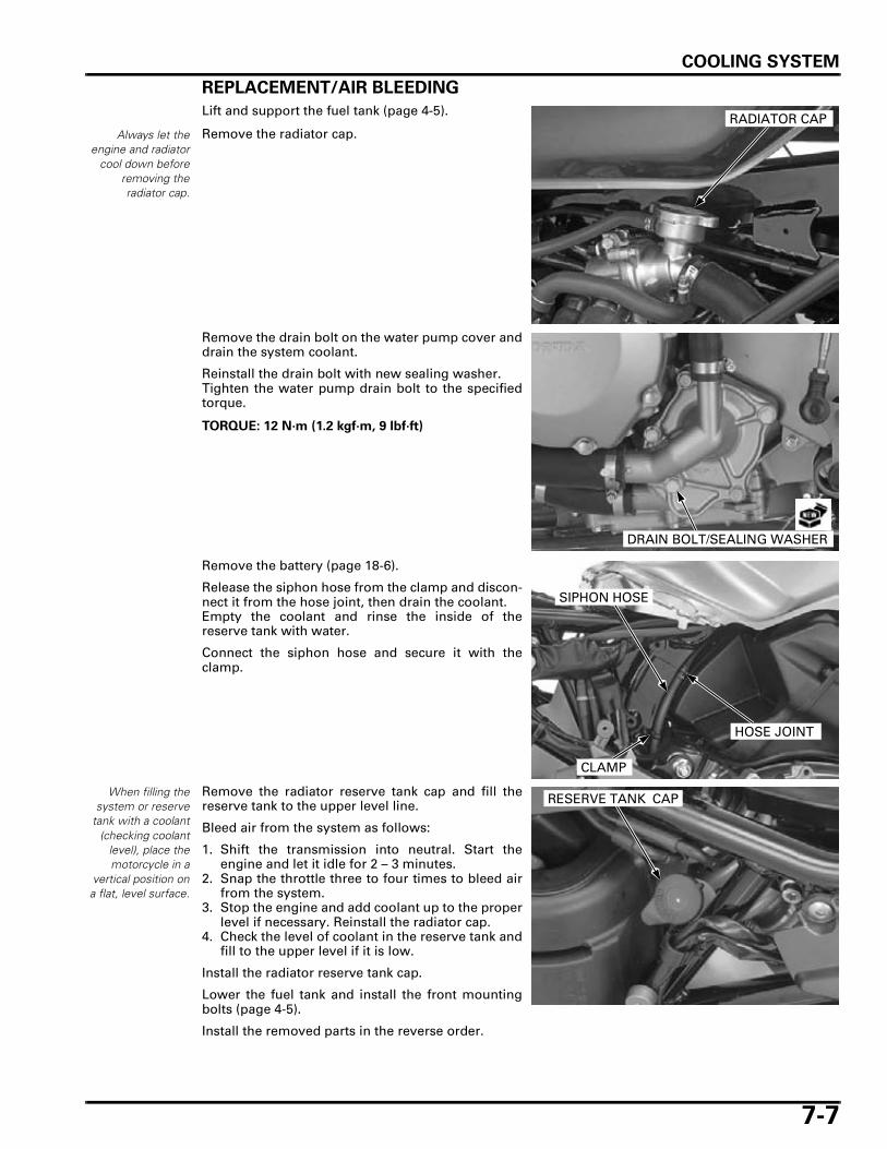
REPLACEMENT/AIR BLEEDING
Lift and support the fuel tank (page 4-5).
Remove the radiator cap.
Remove the drain bolt on the water pump cover anddrain the system coolant.
Reinstall the drain bolt with new sealing washer.Tighten the water pump drain bolt to the specifiedtorque.
Remove the battery (page 18-6).
Release the siphon hose from the clamp and discon-nect it from the hose joint, then drain the coolant.Empty the coolant and rinse the inside of thereserve tank with water.
Connect the siphon hose and secure it with theclamp.
When filling thesystem or reserve
tank with a coolant(checking coolant
level), place themotorcycle in a
vertical position ona flat, level surface.
Remove the radiator reserve tank cap and fill thereserve tank to the upper level line.
Bleed air from the system as follows:
1. Shift the transmission into neutral. Start theengine and let it idle for 2 – 3 minutes.
2. Snap the throttle three to four times to bleed airfrom the system.
3. Stop the engine and add coolant up to the properlevel if necessary. Reinstall the radiator cap.
4. Check the level of coolant in the reserve tank andfill to the upper level if it is low.
Install the radiator reserve tank cap.
Lower the fuel tank and install the front mountingbolts (page 4-5).
Install the removed parts in the reverse order.
Always let theengine and radiator
cool down beforeremoving theradiator cap.
RADIATOR CAP
TORQUE: 12 N·m (1.2 kgf·m, 9 lbf·ft)
DRAIN BOLT/SEALING WASHER
SIPHON HOSE
CLAMP
HOSE JOINT
RESERVE TANK CAP
COOLING SYSTEM
7-8
THERMOSTAT
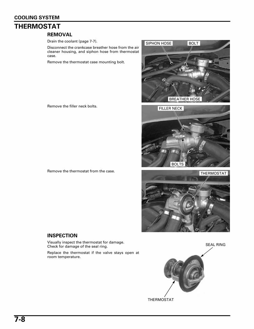
REMOVAL
Drain the coolant (page 7-7).
Disconnect the crankcase breather hose from the aircleaner housing, and siphon hose from thermostatcase.
Remove the thermostat case mounting bolt.
Remove the filler neck bolts.
Remove the thermostat from the case.
INSPECTION
Visually inspect the thermostat for damage.Check for damage of the seal ring.
Replace the thermostat if the valve stays open atroom temperature.
BREATHER HOSE
BOLTSIPHON HOSE
BOLTS
FILLER NECK
THERMOSTAT
THERMOSTAT
SEAL RING

COOLING SYSTEM
7-9
• Wear insulated gloves and adequate eye protec-tion.
• Keep flammable materials away from the electricheating element.
Do not let thethermostat or
thermometer touchthe pan, or you will
get false reading.
Heat the water with an electric heating element tooperating temperature for 5 minutes.Suspend the thermostat in heated water to check itsoperation.
Replace the thermostat if the valve responds at tem-peratures other than those specified.
THERMOSTAT INSTALLATION
Install the thermostat into the case with its air bleedhole facing upward.
Install the filler neck onto the thermostat case.Install and tighten the filler neck bolts securely.
THERMOSTAT BEGIN TO OPEN:
80 – 84 °C (176 – 183 °F)
VALVE LIFT:
8 mm (0.3 in) minimum at 95 °C (203 °F)
THERMOSTAT
THERMOMETER
THERMOSTAT
BLEED HOLE
BOLTS
FILLER NECK

COOLING SYSTEM
7-10
Install the thermostat case onto the frame.
Route the crankcase breather hose properly andconnect it to the air cleaner housing.
Connect the siphon hose to the filler neck.
Fill the system with the recommended coolant andbleed any air (page 7-6).
THERMOSTAT CASE REMOVAL/INSTALLATION
Drain the coolant (page 7-7).
Disconnect the crankcase breather hose.Remove the thermostat case mounting bolt.
Disconnect the ECT sensor connector.If necessary, remove the ECT sensor from the ther-mostat case (page 21-16).
Loosen the hose band screws and disconnect thewater hoses from the thermostat case.
Installation is in the reverse order of removal.
Fill the system with the recommended coolant andbleed any air (page 7-6).
RADIATOR
REMOVAL
Lift and support the fuel tank (page 4-5).Drain the coolant (page 7-7).
Disconnect the fan motor 2P (Black) connector.
BREATHER HOSE
BOLTSYPHON TUBE
BREATHER HOSE
BOLTSIPHON HOSE
THERMOSTAT HOUSING
CONNECTOR
HOSES
2P (Black) CONNECTOR
COOLING SYSTEM
7-11
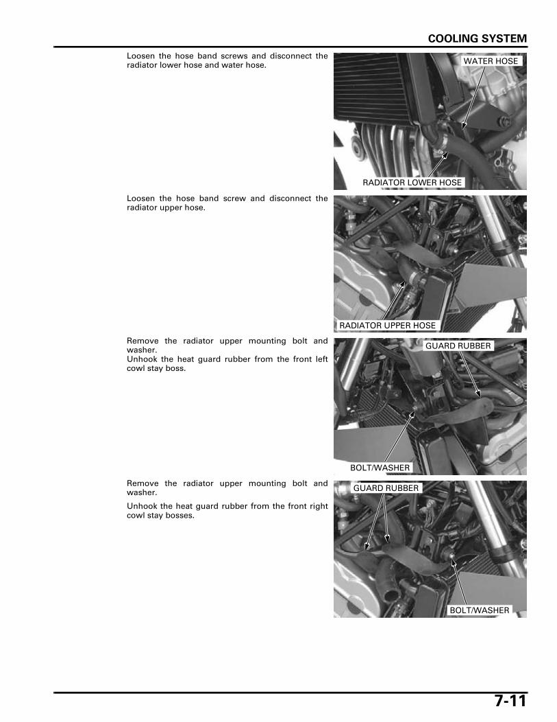
Loosen the hose band screws and disconnect theradiator lower hose and water hose.
Loosen the hose band screw and disconnect theradiator upper hose.
Remove the radiator upper mounting bolt andwasher.Unhook the heat guard rubber from the front leftcowl stay boss.
Remove the radiator upper mounting bolt andwasher.
Unhook the heat guard rubber from the front rightcowl stay bosses.
RADIATOR LOWER HOSE
WATER HOSE
RADIATOR UPPER HOSE
BOLT/WASHER
GUARD RUBBER
BOLT/WASHER
GUARD RUBBER

COOLING SYSTEM
7-12
Be careful not todamage the radiator
fins.
Slide the radiator assembly and release the radiatorlower grommets from the frame bosses, thenremove the radiator assembly.
DISASSEMBLY
Remove the heat guard rubber from the radiatorassembly.
Remove the three bolts and cooling fan motorassembly from the radiator.
Remove the nut and cooling fan.
GROMMETBOSS
HEAT GUARD RUBBER
FAN MOTOR ASSEMBLY
BOLTS
COOLING FAN
NUT
COOLING SYSTEM
7-13
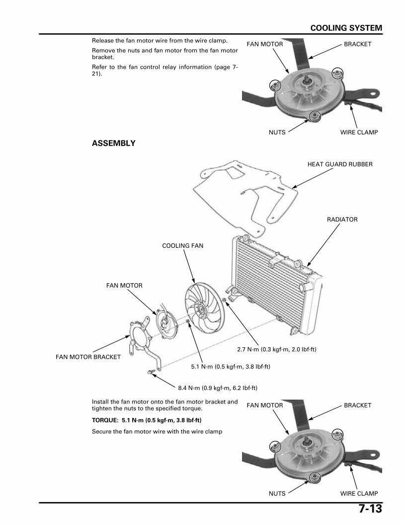
Release the fan motor wire from the wire clamp.
Remove the nuts and fan motor from the fan motorbracket.
Refer to the fan control relay information (page 7-21).
ASSEMBLY
Install the fan motor onto the fan motor bracket andtighten the nuts to the specified torque.
Secure the fan motor wire with the wire clamp
FAN MOTOR BRACKET
NUTS WIRE CLAMP
8.4 N·m (0.9 kgf·m, 6.2 lbf·ft)
RADIATOR
2.7 N·m (0.3 kgf·m, 2.0 lbf·ft)
COOLING FAN
FAN MOTOR BRACKET
5.1 N·m (0.5 kgf·m, 3.8 lbf·ft)
FAN MOTOR
HEAT GUARD RUBBER
TORQUE: 5.1 N·m (0.5 kgf·m, 3.8 lbf·ft)
FAN MOTOR BRACKET
NUTS WIRE CLAMP
COOLING SYSTEM
7-14
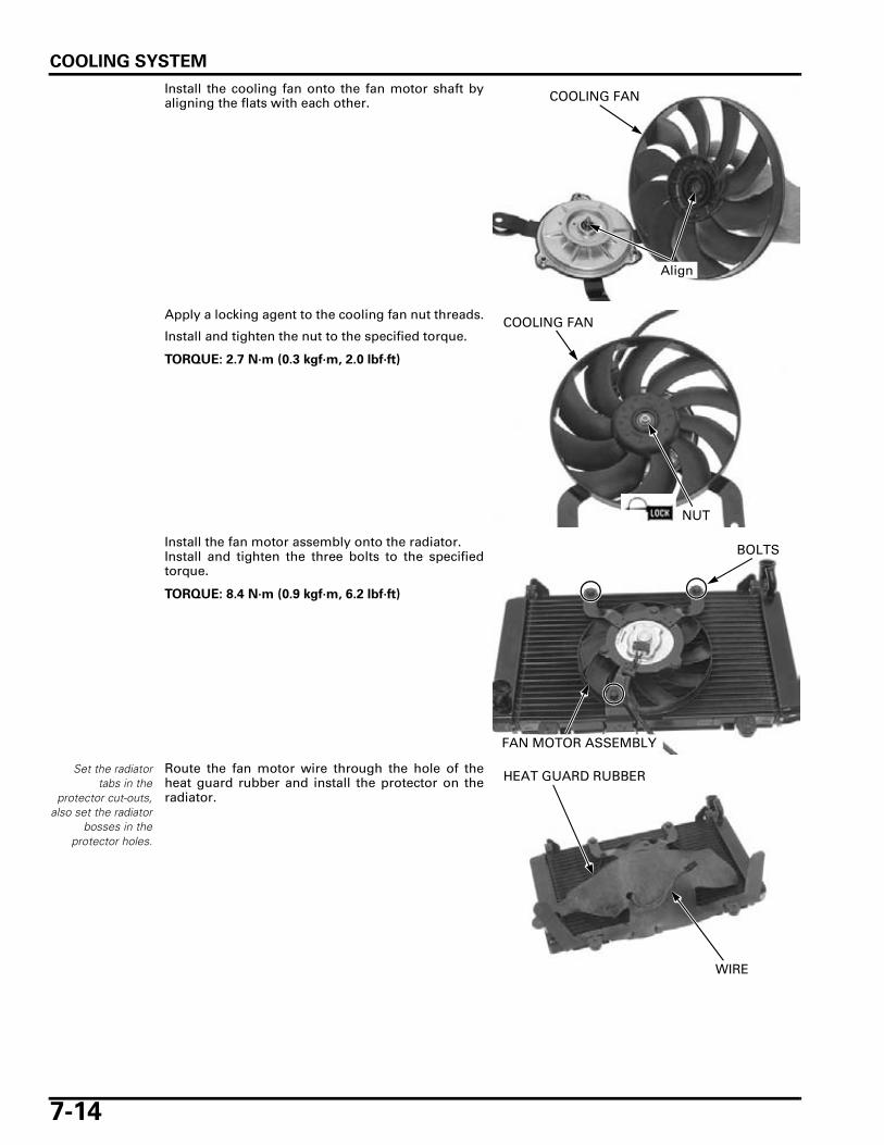
Install the cooling fan onto the fan motor shaft byaligning the flats with each other.
Apply a locking agent to the cooling fan nut threads.
Install and tighten the nut to the specified torque.
Install the fan motor assembly onto the radiator.Install and tighten the three bolts to the specifiedtorque.
Set the radiatortabs in the
protector cut-outs,also set the radiator
bosses in theprotector holes.
Route the fan motor wire through the hole of theheat guard rubber and install the protector on theradiator.
Align
COOLING FAN
TORQUE: 2.7 N·m (0.3 kgf·m, 2.0 lbf·ft)
COOLING FAN
NUT
TORQUE: 8.4 N·m (0.9 kgf·m, 6.2 lbf·ft)
FAN MOTOR ASSEMBLY
BOLTS
HEAT GUARD RUBBER
WIRE

COOLING SYSTEM
7-15
INSTALLATION
Be careful not todamage the radiator
fins.
Align the radiator lower grommets with the framebosses and install the radiator assembly.
Spread the heat guard rubber on the cylinder headcover.
Install the washer and radiator upper mounting bolt,and tighten the bolt securely.
Hook the heat guard rubber on the side cowl stayboss.
Install the washer and radiator upper mounting bolt,and tighten the bolt securely.
Hook the heat guard rubber on the side cowl staybosses.
Connect the water hose and radiator lower hose.Tighten the hose band screws securely.
GROMMETBOSS
BOLT/WASHER
GUARD RUBBER
BOLT/WASHER
GUARD RUBBER
RADIATOR LOWER HOSE
WATER HOSE
COOLING SYSTEM
7-16
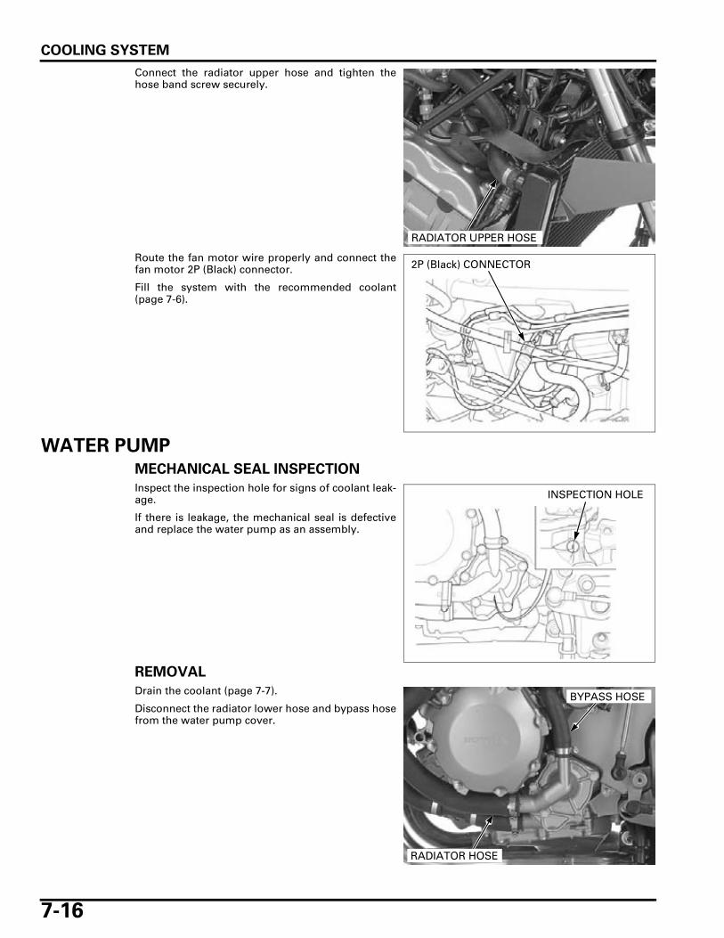
Connect the radiator upper hose and tighten thehose band screw securely.
Route the fan motor wire properly and connect thefan motor 2P (Black) connector.
Fill the system with the recommended coolant(page 7-6).
WATER PUMP
MECHANICAL SEAL INSPECTION
Inspect the inspection hole for signs of coolant leak-age.
If there is leakage, the mechanical seal is defectiveand replace the water pump as an assembly.
REMOVAL
Drain the coolant (page 7-7).
Disconnect the radiator lower hose and bypass hosefrom the water pump cover.
RADIATOR UPPER HOSE
2P (Black) CONNECTOR
INSPECTION HOLE
RADIATOR HOSE
BYPASS HOSE
COOLING SYSTEM
7-17
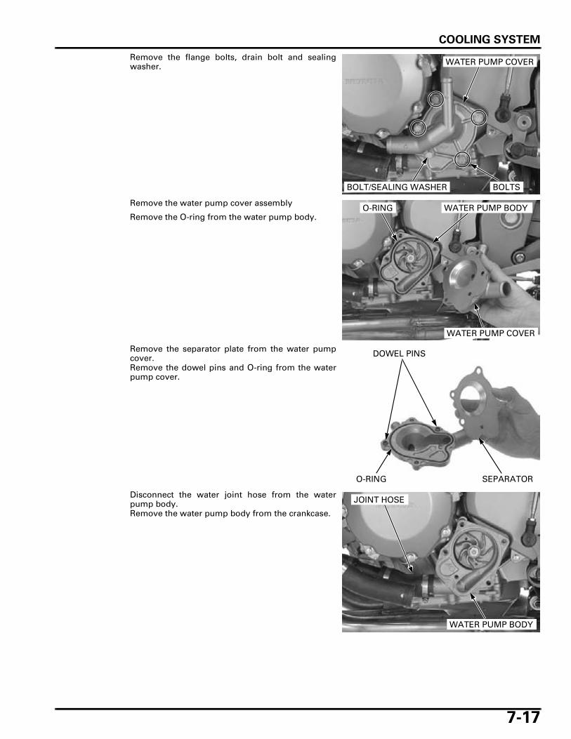
Remove the flange bolts, drain bolt and sealingwasher.
Remove the water pump cover assembly
Remove the O-ring from the water pump body.
Remove the separator plate from the water pumpcover.Remove the dowel pins and O-ring from the waterpump cover.
Disconnect the water joint hose from the waterpump body.Remove the water pump body from the crankcase.
WATER PUMP COVER
BOLTSBOLT/SEALING WASHER
O-RING WATER PUMP BODY
WATER PUMP COVER
SEPARATORO-RING
DOWEL PINS
JOINT HOSE
WATER PUMP BODY
COOLING SYSTEM
7-18
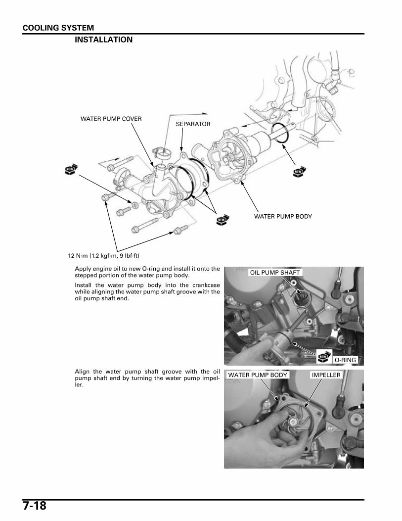
INSTALLATION
Apply engine oil to new O-ring and install it onto thestepped portion of the water pump body.
Install the water pump body into the crankcasewhile aligning the water pump shaft groove with theoil pump shaft end.
Align the water pump shaft groove with the oilpump shaft end by turning the water pump impel-ler.
WATER PUMP BODY
WATER PUMP COVER
12 N·m (1.2 kgf·m, 9 lbf·ft)
SEPARATOR
O-RING
OIL PUMP SHAFT
WATER PUMP BODY IMPELLER
COOLING SYSTEM
7-19
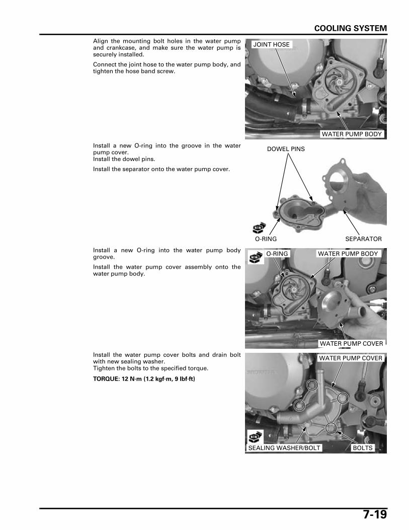
Align the mounting bolt holes in the water pumpand crankcase, and make sure the water pump issecurely installed.
Connect the joint hose to the water pump body, andtighten the hose band screw.
Install a new O-ring into the groove in the waterpump cover.Install the dowel pins.
Install the separator onto the water pump cover.
Install a new O-ring into the water pump bodygroove.
Install the water pump cover assembly onto thewater pump body.
Install the water pump cover bolts and drain boltwith new sealing washer.Tighten the bolts to the specified torque.
JOINT HOSE
WATER PUMP BODY
SEPARATORO-RING
DOWEL PINS
O-RING WATER PUMP BODY
WATER PUMP COVER
TORQUE: 12 N·m (1.2 kgf·m, 9 lbf·ft)
WATER PUMP COVER
BOLTSSEALING WASHER/BOLT

COOLING SYSTEM
7-20
Connect the radiator lower hose and bypass hose,then tighten the hose band screws.
Fill the system with the recommended coolant(page 7-6).
RADIATOR RESERVE TANK
REMOVAL
Remove the following:
– Shock absorber (page 15-13)– Battery (page 18-6)
Release the siphon hose from the clamper and dis-connect it from the hose joint, then drain the cool-ant.
Remove the bolts and radiator reserve tank.
Installation is in the reverse order of removal.
• Secure the siphon hose and reserve tank over-flow hose with the frame clamper as shown.
Fill the reserve tank with coolant (page 7-7).
RADIATOR HOSE
BYPASS HOSE
SIPHON HOSE
CLAMPER
HOSE JOINT
BOLTS
RESERVE TANK
OVERFLOW HOSE
CLAMPER
SIPHON HOSE
OVERFLOW HOSE
COOLING SYSTEM
7-21
FAN CONTROL RELAY
INSPECTION
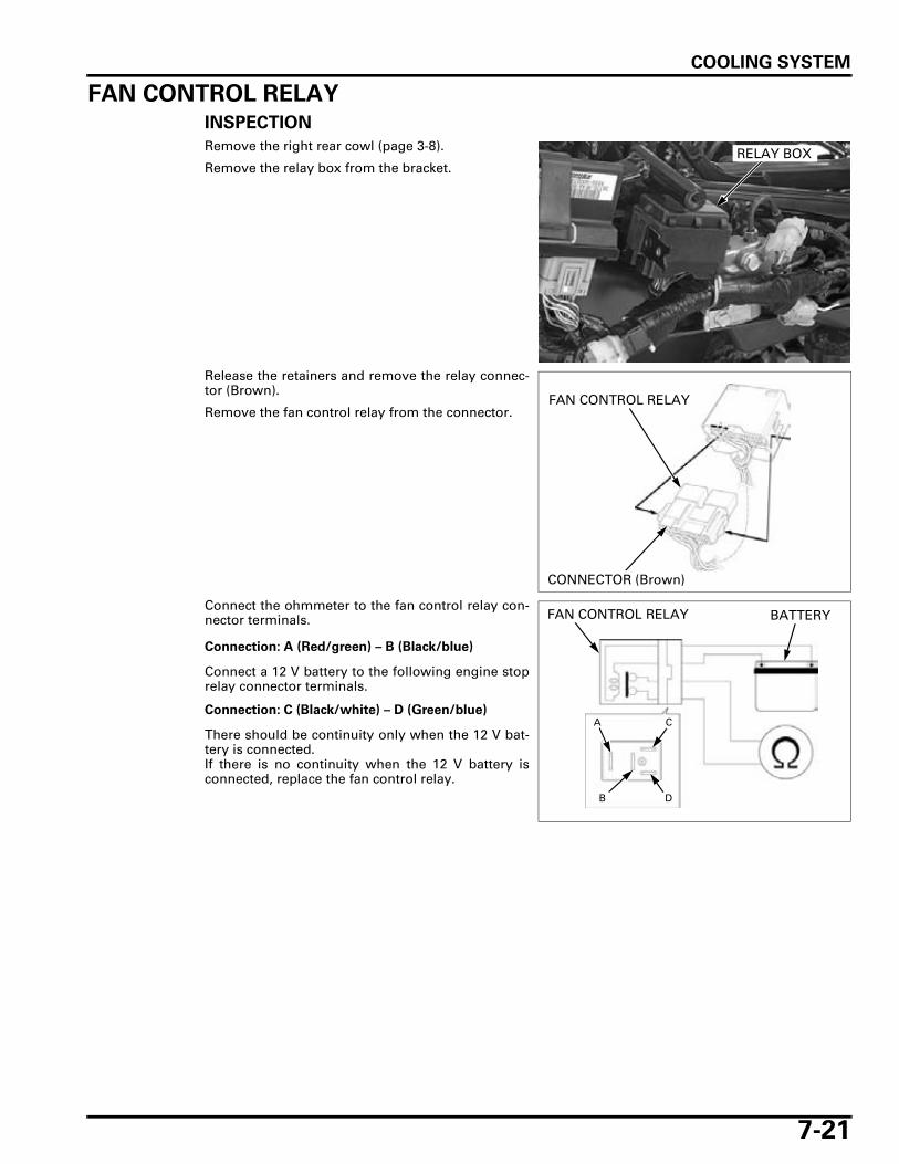
Remove the right rear cowl (page 3-8).
Remove the relay box from the bracket.
Release the retainers and remove the relay connec-tor (Brown).
Remove the fan control relay from the connector.
Connect the ohmmeter to the fan control relay con-nector terminals.
Connect a 12 V battery to the following engine stoprelay connector terminals.
There should be continuity only when the 12 V bat-tery is connected.If there is no continuity when the 12 V battery isconnected, replace the fan control relay.
RELAY BOX
FAN CONTROL RELAY
CONNECTOR (Brown)
Connection: A (Red/green) – B (Black/blue)
Connection: C (Black/white) – D (Green/blue)
BATTERY
A C
DB
FAN CONTROL RELAY
MEMO