2005 pro master manual
DESCRIPTION
Indian Creek Designs Promaster Paintball marker user manualTRANSCRIPT

RULES FOR SAFE MARKER HANDLING
1) Treat every marker as if it were loaded.
2) Never look down the barrel of a paintball marker.
3) Keep your finger off the trigger until ready to shoot.
4) Never point the marker at anything you don’t wish to shoot.
5) Keep the marker on safe until ready to shoot.
6) Keep the barrel blocking device in/on the marker’s muzzle when not
shooting.
7) Always remove paintballs and propellant source before disassembly.
8) After removing propellant source, point marker in safe direction and dis-
charge until marker is degassed.
9) Store the marker unloaded and de-gassed in a secure place.
10) Follow warnings listed on propellant source for handling and storage.
11) Do not shoot at fragile objects such as windows.
12) Every person within range must wear eye, face, and ear protection
designed specifically to stop paintballs and meeting ASTM standard
F1776.
13) Always measure your marker’s velocity before playing paintball and
never shoot at velocities in excess of 91.44 meters (300 feet) per second.
ProMasterTM Manual 1
ICD PROMASTER™ MANUAL-REV1 6/15/05 6:00 PM Page 1
INSTRUCTION MANUAL
Version 1.2
Indian Creek Design, Inc.
PROMASTERTM
Copyright 1992…. 2005
All Rights Reserved
No part of this document may be copied or reproduced in any form or by any means without the prior
written consent of Indian Creek Design, Inc., its assigns and/or its distributors.
Notice is hereby given that this manual is part of the article owned in whole by Indian Creek Design,
Inc., its assigns and/or its distributors, known as indicated in this manual and drawings. All rights of
manufacture and reproduction of such articles or any part thereof are reserved by Indian Creek
Design, Inc., its assigns and/or its distributors. Neither said article nor any part thereof may be
manufactured or reproduced except by written authorization from Indian Creek Design, Inc., its
assigns and/or its distributors. All proprietary rights and information are the sole property of Indian
Creek Design, Inc., its assigns and/or its distributors.
2 ProMasterTM Manual
ICD PROMASTER™ MANUAL-REV1 6/15/05 6:01 PM Page 2
ProMasterTM Manual 3
STATEMENT OF LIABILITY
Indian Creek Design, Inc., delivers this marker with the understanding that Indian Creek Design, Inc.,
its assigns and/or its distributors, assumes no responsibility for its resale or safe handling. Serious
injury or death may occur if mishandled, abused, or the safety instructions are ignored. Indian Creek
Design, Inc., its assigns and/or its distributors assumes no responsibility for physical injury or
property damage resulting from its use.
Indian Creek Design, Inc., its assigns and/or its distributors, makes no warranties with respect to this
documentation and disclaims any implied warranties of merchantability or fitness for a particular pur-
pose. The information in this document is subject to change without notice. Indian Creek Design,
Inc., its assigns and/or distributors assumes no responsibility for any errors that may appear in this
document.
WARNING:
This is not a toy. Misuse may cause serious injury or death. Eye protection designed specifically for
paintball use must be worn by the user and any person within range. Recommend 18 years of age or
older to purchase. Persons under 18 years of age must have adult supervision. Obey all local, state
and federal laws. Follow the rules of safe paintball marker handling.
READ OWNER’S MANUAL BEFORE USING.
ProMasterTM Manual 3
ICD PROMASTER™ MANUAL-REV1 6/15/05 6:01 PM Page 3

4 ProMasterTM Manual
INDIAN CREEK DESIGN, INC.
LIMITED WARRANTY
Indian Creek Design, Inc., warrants the replacement of any original part due to defect in materials
and/or workmanship of this marker. This warranty does not cover wearable items such as but not
limited to o-rings, cup seals and springs. This warranty will be in effect for twelve (12) months for
parts and twelve (12) months for labor following the original date of purchase for the original
purchaser. Such warranty service will be provided only if the warranty registration card included with
this manual is filled in completely and on file at Indian Creek Design, Inc. All other service will be
duly charged for and returned via UPS C.O.D.
Indian Creek Design, Inc., will replace without charge any original part that is determined by Indian
Creek Design, Inc., to be defective under the term of this warranty. However, shipping charges are
not covered hereunder. Failure due to an accident, abuse, neglect, modification, normal wear,
operator error, maintenance by other than an authorized Indian Creek Design, Inc., dealer, or use of
parts inconsistent with the use originally intended for the marker as sold, is not covered by
this warranty.
There are no other warranties or guarantees, expressed or implied, made by Indian Creek Design, Inc.,
on this marker. The sole and exclusive liability of Indian Creek Design, Inc., and/or its authorized
dealers, affiliates, or agents pursuant to this warranty will be for repair or replacement of the
defective part; incidental or consequential damages are expressly excluded hereunder.
Indian Creek Design, Inc., its authorized dealers, affiliates, or agents, will not be liable under this
warranty, nor under any state or federal law, or the common law or otherwise for any damage or
failure, including personal injury, resulting from such use and/or alteration. This warranty gives you
specific legal rights, and you may also have other rights that may vary from state to state.
For warranty parts, service or information contact:
Indian Creek Design, Inc.
1019 First Street North
Nampa, Idaho 83687
(208) 468-0446
4 ProMasterTM Manual
ICD PROMASTER™ MANUAL-REV1 6/15/05 6:02 PM Page 4

ProMasterTM Manual 5
PROMASTERTM OVERVIEW
The PROMASTERTM is a high quality marker specially designed to meet the needs of the
professional style tournament player. The PROMASTERTM is an electronic solenoid actuated
computer controlled marker. The major components of the PROMASTERTM are machined from solid,
aircraft-grade aluminum, and then hard anodized. No castings are used in the construction of the
PROMASTERTM, thereby providing the end user with a high-quality, precision-engineered
marker.
Paintball markers get a lot of abuse. Indian Creek Design, Inc., has designed the PROMASTERTM
with this in mind. All internal parts, wear and contact surfaces have been heat treated or hard
anodized. The toughest and most resilient materials and components have been used in the design of
this product.
The PROMASTERTM uses a single standard 9-volt battery for operation. The circuitry is a
microprocessor based digital controller.
The PROMASTERTM operates on low-pressure. The main operating pressure is 250-300 PSI
nominally adjusted to visually via the gauge on the primary (input) regulator. The secondary pressure
is factory pre-set and regulated to 85-95 PSI. Gas usage is controlled through these 2 internal
regulators. A unique feature of this marker is the regulator adjustment. This allows precise adjustment
for the velocity control of the marker and for optimal gas efficiency.
The PROMASTERTM comes with a removable barrel system. This feature allows the user to select a
barrel that is most suitable for the playing conditions. All barrels are honed with straight and spiral
tip porting and stock length is 11".
ProMasterTM Manual 5
ICD PROMASTER™ MANUAL-REV1 6/15/05 6:02 PM Page 5

6 ProMasterTM Manual
OPERATION
Read the entire manual before you prepare your PROMASTERTM for play. Safety and safe marker
handling are the most important aspects of the sport of paintball. Please practice each of the follow-
ing steps with an unloaded marker before attempting to charge your marker with compressed air and
paintballs. Do not load compressed air and paintballs into your PROMASTERTM until you feel com-
pletely confident with your ability to handle your PROMASTERTM safely.
NOTE: Part numbers matching the exploded diagram (located on page 12) are shown in parentheses
throughout this manual.
Keep your finger out of the trigger guard and away from the trigger; point the muzzle of the marker
in a safe direction at all times. Keep the marker turned off until ready to operate. The PROMAS-
TERTM uses an on-off switch as one of its safety features. Always keep your PROMASTERTM point-
ed in a safe direction. Always use a barrel plug or barrel blocking device. Remember that the ulti-
mate safety device is you, the operator.
Installing the 9 volt Power Source
The PROMASTERTM requires a single 9-volt battery as the electronic power source. The use of long
life batteries is recommended.
The 9-volt battery is located in the grip behind the trigger and below the on-off switch. The battery
is accessed through the right grip located on the right side of the marker.
Remove the two screws (54) that hold the grip panel in place. Slide the Grip Panel out of the way.
Remove the four screws (56) that hold the right clamshell in place. Carefully lift the clamshell up and
away from the marker. Connect the battery to the terminal and place the battery inside the frame care-
fully, being sure that the black and red wires to the terminal are toward the top. Make sure that there
are no abrupt kinks and the wires are comfortably placed, do not force them into place. Replace the
right clamshell grip and tighten the 4 screws (56). Replace the grip panel and 2 screws(54).
ICD PROMASTER™ MANUAL-REV1 6/15/05 6:02 PM Page 6
COMPRESSED AIR USAGE
DANGER:
Cylinders can fly off with enough force to kill if the valve unscrews from the cylinder. STOP if the
cylinder starts to unscrew from the valve. Screw the cylinder back on and take it to a qualified person
to repair.
The PROMASTERTM comes with a female – Push-In fitting adapter on the input of the regulator. The
PROMASTERTM can be set up to use a nitrogen or compressed air system. Although it may be used,
CO2 is not recommended for use as the propellant. Generally the CO2 that we use as an industry is
industrial grade CO2. It is dirty, pumped from large tanks full of contaminates including dirt, rust
and metal flakes. CO2 can be used most successfully if used with anti-siphon systems and filters.
Be aware that under the conditions of CO2 the results may not be as expected. Consult the place
where you purchased your PROMASTERTM, or a recognized and competent airsmith, for instruction in the safe
handling of compressed-air cylinders before purchasing or connecting one to your PROMASTERTM.
Adjustable regulator compressed air systems:
The input pressure from your compressed air system should be regulated down to 450-500 PSI
output pressure. Use a VERY HIGH FLOW low pressure output tank and regulator set-up for your
best results. The PROMASTERTM will work just fine with a pre-set regulated tank or an adjustable
output regulated tank. Note: on MOST systems, there is a large difference between cylinder’s filled
pressure and the actual output operating pressure.
Fixed output regulated compressed air systems:
The PROMASTERTM will work just fine with a pre-set output air system although, you will get much
better performance from a HIGH FLOW low output pressure tank/regulator than with a high pressure
(750-850) output. You must VERIFY the output pressure from the regulator. If your compressed air
system does not have an output pressure gauge on its regulator, we do not recommend its use.
Continued>>>
ProMasterTM Manual 7
ICD PROMASTER™ MANUAL-REV1 6/15/05 6:03 PM Page 7

8 ProMasterTM Manual
CO2 usage:
Although it may be used, CO2 is not recommended for use as the propellant. Generally the CO2 that
we use as an industry is industrial grade CO2. It is dirty, pumped from large tanks full of contami-
nates including rust and metal flakes. CO2 can be used most successfully if used with anti-siphon
systems and filters. Be aware that the use of CO2 may result in less than optimal performance. CO2
use is NOT covered under warranty.
REMEMBER: CO2, compressed air or nitrogen systems can be extremely dangerous if misused
or improperly handled. Use only cylinders meeting D.O.T., T.C, Pi or other specifications as
applicable to your location. Do not perform any work to your tank or tank regulator. NEVER
disassemble your tank or tank regulator. Only a qualified and trained technician should perform work
to your tank and tank regulator.
Before pressurizing your PROMASTERTM, check to make sure that you and anyone within range are
wearing eye protection designed specifically for paintball. Be sure you have a barrel blocking device
in place and make sure there are no paintballs in the marker. The on-off switch should be OFF. Air
can now be applied, the marker will become pressurized and the bolt will slide backwards.
ICD PROMASTER™ MANUAL-REV1 6/15/05 6:03 PM Page 8

ProMasterTM Manual 9
PAINTBALLAND LOADER USAGE
The PROMASTERTM comes equipped to accept 1.03" OD feed neck loaders. Fit the loader directly
into the vertical feed tube. Always twist it down in a CLOCKWISE direction. Always twist it off in
a CLOCKWISE direction as well. The PROMASTERTM uses .68 caliber,
water-soluble paintballs. The paintballs are gravity fed from the loader through the direct vertical feed
nipple and into the breech of the marker.
ProMasterTM Manual 9
2000 PAINTBALLS2000 PAINTBALLS
Always Point in A SAFE DIRECTION
INSTALLING THE LOADER
USE .68 Caliber water soluble paintballs
ICD PROMASTER™ MANUAL-REV1 6/15/05 6:03 PM Page 9

10 ProMasterTM Manual
MODES - RATE-OF-FIRE
The PROMASTERTM will fire “Semi-Auto” or single shot per trigger pull with a maximum rate of fire
governed to 15 balls-per-second or unlimited. The PROMASTERTM may also be set in three differ-
ent enhanced modes. These include “Ramp”, “Ramp-Auto” and “Ramp-Burst”.
SETTING MODES, RATE-OF-FIRE AND DWELL
Before adjusting firing modes, rate of fire or dwell, always remove propellant source from the
PROMASTERTM, install barrel blocking device and make sure the on-off slide switch is in the “Off”
position (LED will be off).
1) Place PROMASTERTM on a flat surface with muzzle pointing to the right.
2) Using a 5/64 hex wrench, remove the two grip panel screws (55) and pull back the wrap
around grip cover (64). This will expose a set of 4 dip switches labeled 1 through 4.
3) The dip switches are off when pointing away from the printed numbers on the switch
box and are on when pointing towards the printed numbers on the switch box.
4) The following covers the dip switch settings and the corresponding firing modes:
ICD PROMASTER™ MANUAL-REV1 6/15/05 6:04 PM Page 10

ProMasterTM Manual 11
SETTING MODES, RATE-OF-FIRE AND DWELL
Rate of Fire - Balls Per Second (BPS) Controlling Switch
Switch #1 is only used to control BPS limits. When Switch #1 is in the ON position the BPS is
limited to 15. When Switch #1 is in the OFF position, the BPS is only limited by the marker’s
maximum cycling speed which may vary depending on pressure inputs, dwell setting and other
considerations.
Setting Firing Modes
ProMasterTM Manual 11
1
2
34
4321
1
2
34
4321
1
2
34
4321
1
2
34
4321
1
2
34
4321
1
2
34
4321
1
2
34
4321
1
2
34
4321
Semi-Automatic -
15BPS Limit
Ramp Automatic -
15BPS Limit
Ramp -
15BPS Limit
Ramp Burst -
15BPS Limit
Semi-Automatic -
Unlimited BPS
Ramp Automatic -
Unlimited BPS
Ramp -
Unlimited BPS
Ramp Burst -
Unlimited BPS
ICD PROMASTER™ MANUAL-REV1 6/15/05 6:04 PM Page 11
12 ProMasterTM Manual
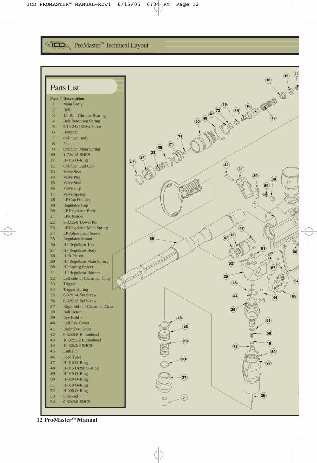
Part # Description 1 Main Body 2 Bolt 3 1/4 Bolt Chrome Bearing 4 Bolt Retention Spring 5 5/16-24x1/2 Set Screw 6 Hammer 7 Cylinder Body 8 Piston 9 Cylinder Main Spring10 1-72x1/2 SHCS11 H-015 O-Ring12 Cylinder End Cap13 Valve Seat14 Valve Pin15 Valve Seal16 Valve Cup17 Valve Spring18 LP Cup Housing19 Regulator Cup20 LP Regulator Body21 LPR Piston22 3-32x5/8 Dowel Pin23 LP Regulator Main Spring24 LP Adjustment Screw25 Regulator Mount26 HP Regulator Top27 HP Regulator Body28 HPR Piston29 HP Regulator Main Spring30 HP Spring Spacer31 HP Regulator Bottom32 Left side of Clamshell Grip33 Trigger34 Trigger Spring35 8-32x1/4 Set Screw36 8-32x1/2 Set Screw37 Right Side of Clamshell Grip38 Ball Detent39 Eye Holder40 Left Eye Cover41 Right Eye Cover42 6-32x5/8 Buttonhead43 10-32x1/2 Buttonhead44 10-32x3/4 SHCS45 Link Pin46 Feed Tube47 H-016 O-Ring48 H-015 UR90 O-Ring49 H-019 O-Ring50 H-020 O-Ring51 H-010 O-Ring52 H-006 O-Ring53 Solenoid54 6-32x3/8 SHCS
47
4821
71
2049
4773
19
5818
4241
39
59
38
54
67
6544
5651
47
1347
52
25
66
48
44
26
78
5148
28
29
30
31
5
58
19
50
27
28
1
6
17
1615
14
2423
Parts List
ICD PROMASTER™ MANUAL-REV1 6/15/05 6:04 PM Page 12

ProMasterTM Manual 13
46
452
3
7 4
5
8 51
11
54 70
43
57
69
37
54
65
56
3938
5940
42
22
60
33
53
35
34
36
35
54 32
54
71
55
55
64
72
10
74
68
9
651
67
6362
12
514
Part # Description55 6-32x1/4 Button Head56 6-32x3/8 SHCS57 3-8/24x1/4 Set Screw58 Regulator Cup Spring59 Anti-Double Feed Spring60 Circuit Board61 Barrel Plug62 Cylinder Spring Assist Sleeve63 Cylinder Spring Guide64 Rubber Grip65 700 p.s.i. Gauge66 Barrel67 10/32 Barb68 QEV69 90 Degree 3 MM Barb70 3 Millimeter Barb71 On/Off Switch72 3/48x3/16 Pan Head Phillips Machine Screw73 Regulator Seal74 1-72x3/8 SHCS
Parts List (Contʼd.)
ICD PROMASTER™ MANUAL-REV1 6/15/05 6:04 PM Page 13

14 ProMasterTM Manual
Dwell Setting – Electronic Impulse Controlling Switch
Switch #4 is only used to control the length of the electronic impulse sent to actuate the solenoid. The
longer the dwell setting the slower the maximum cycling rate but the stronger the impulse to the
solenoid. The shorter the dwell setting the faster the potential cycling rate but the more likely to
experience skipping.
CAUTION: Over shortening the dwell time will render the ProMaster inoperable.
To Adjust Dwell Setting
1) Turn Switch 4 to ON position.
2) Pull trigger and hold.
3) Turn on marker.
4) While watching the LED (Light Emitting Diode), release trigger.
5) Count the number of LED flashes, 1 flash = 1 millisecond dwell 8 flashes = 8 milliseconddwell. After flashing has stopped, LED will stay on.
6) Pull and release trigger one time for every desired millisecond of dwell. Wait at least 1 butless than 5 seconds between each trigger pull and release.
7) Each trigger pull will cause LED to flash once.
8) After trigger pulls wait 10 seconds and marker will flash LED with the new dwell count.
9) Turn marker off.
10) Turn off switch 4 to lock in new dwell setting.
14 ProMasterTM Manual
ICD PROMASTER™ MANUAL-REV1 6/15/05 6:04 PM Page 14
ProMasterTM Manual 15
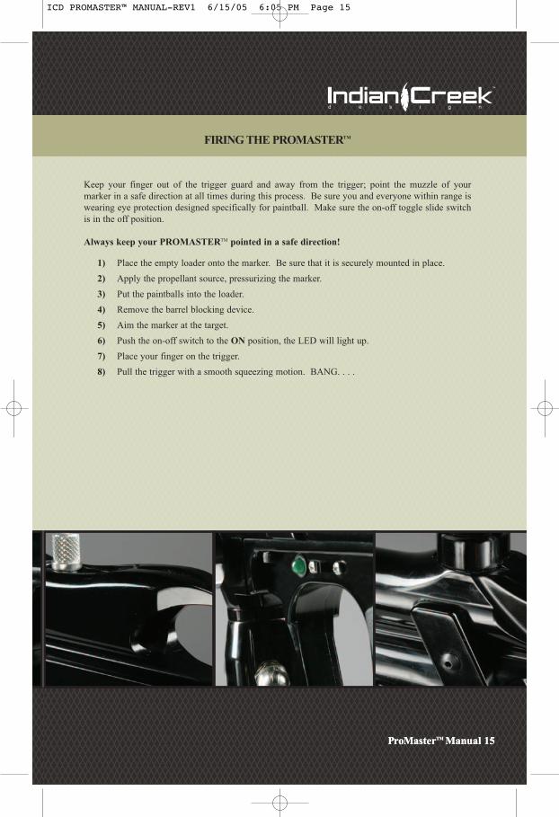
FIRING THE PROMASTERTM
Keep your finger out of the trigger guard and away from the trigger; point the muzzle of your
marker in a safe direction at all times during this process. Be sure you and everyone within range is
wearing eye protection designed specifically for paintball. Make sure the on-off toggle slide switch
is in the off position.
Always keep your PROMASTERTM pointed in a safe direction!
1) Place the empty loader onto the marker. Be sure that it is securely mounted in place.
2) Apply the propellant source, pressurizing the marker.
3) Put the paintballs into the loader.
4) Remove the barrel blocking device.
5) Aim the marker at the target.
6) Push the on-off switch to the ON position, the LED will light up.
7) Place your finger on the trigger.
8) Pull the trigger with a smooth squeezing motion. BANG. . . .
ProMasterTM Manual 15
ICD PROMASTER™ MANUAL-REV1 6/15/05 6:05 PM Page 15
16 ProMasterTM Manual
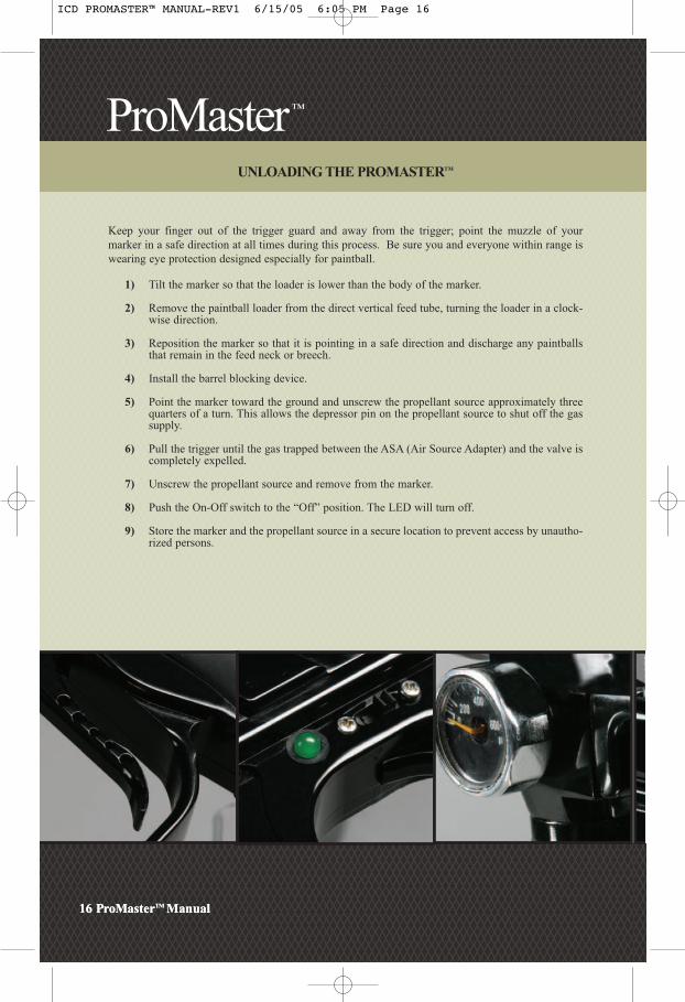
UNLOADING THE PROMASTERTM
Keep your finger out of the trigger guard and away from the trigger; point the muzzle of your
marker in a safe direction at all times during this process. Be sure you and everyone within range is
wearing eye protection designed especially for paintball.
1) Tilt the marker so that the loader is lower than the body of the marker.
2) Remove the paintball loader from the direct vertical feed tube, turning the loader in a clock-wise direction.
3) Reposition the marker so that it is pointing in a safe direction and discharge any paintballsthat remain in the feed neck or breech.
4) Install the barrel blocking device.
5) Point the marker toward the ground and unscrew the propellant source approximately threequarters of a turn. This allows the depressor pin on the propellant source to shut off the gassupply.
6) Pull the trigger until the gas trapped between the ASA (Air Source Adapter) and the valve iscompletely expelled.
7) Unscrew the propellant source and remove from the marker.
8) Push the On-Off switch to the “Off” position. The LED will turn off.
9) Store the marker and the propellant source in a secure location to prevent access by unautho-rized persons.
16 ProMasterTM Manual
ICD PROMASTER™ MANUAL-REV1 6/15/05 6:05 PM Page 16

ProMasterTM Manual 17
MAINTENANCE
CAUTION: Before attempting to perform any maintenance operations or any marker disassem-
bly, make sure that all paintballs and propellant sources have been removed from the marker. Install
a barrel blocking device, push the on-off switch to the OFF position and keep the marker in this
"SAFE" mode.
Simple Maintenance
Keep your PROMASTERTM clean and lubricated to eliminate the friction that would prevent reliable
operation. Clean and lube the marker before each use, and do not put it away dirty. USE NO OILS!
Do not use oils made for paintball markers, real firearms or pneumatic tools, do not use oils at all. Do
not use petroleum-based lubricants in the lubrication of this marker. Teflon or silicon spray lubricants
may be used for lubrication for the bolt area only of the main housing. Lithium grease such as Dow
33 is recommended for lubricating the regulator pistons and the cylinder assembly. Be sure it is
Lithium Grease and not axle grease.
Cleaning Paint from the Barrel
Unscrew the barrel to remove for swabbing/cleaning. Keep the barrel clean to insure the continued
accuracy of the PROMASTERTM. Gelatin from the paintballs has a tendency to build up in the bar-
rel. As part of your regular cleaning process, wash out the barrel with hot soapy water and rinse it
well.
PDS (Paintball Detection System)
The PDS is designed to detect whether or not a paintball is seated in the breech ready to fire. If a
paintball is not there, it will not cycle. To dry fire the marker without the PDS system, hold in the
trigger while turning the marker on. and wait for the LED to stop flashing. If you attempt to dry fire
the marker with the PDS on, the marker will only fire once and then stop firing. Keep the infrared
emitters and detectors clean for your best results.
ProMasterTM Manual 17
ICD PROMASTER™ MANUAL-REV1 6/15/05 6:05 PM Page 17

18 ProMasterTM Manual
Removing the Bolt/Cylinder Assembly (Field Stripping)
Remove the paintballs and propellant source from the marker. While the marker may be field-stripped
while pressurized, this is not recommended.
1) Remove the link pin from the top of the marker. Pull the bolt out the back of the main body.
Once the bolt assembly is removed, it is possible to clean the entire upper receiver of the marker,
including the breech and feed tube area. You may slightly lubricate the rear section of the bolt with
a light synthetic spray before re-installing the bolt. Do not use petroleum/oil-based lubricants. The
bolt tip is NOT a simple plastic; it is a natural Delrin acetate material, which is a Dupont 3M materi-
al, developed specifically for this type of application. The use of a metal tipped bolt will void all war-
ranties.
2) Point the barrel downward and slide the bolt in until the link pin hole lines up with the slotin the hammer. VERIFY that the air passage hole in the tip of the bolt is facing down.Carefully install the link pin. Slide the link pin back and forth to verify that it is properlyseated in the groove of the hammer.
CAUTION: YOU MUST BE SURE THAT THE LINK PIN IS ENGAGED PROPERLY WITH THE HAMMER. IF THELINK PIN IS NOT PROPERLY REPLACED, YOU MAY DAMAGE THE HAMMER/CYLINDER ASSEMBLY.
18 ProMasterTM Manual
WRONG! RIGHT! Link Pin Placement:
Verify that the Link Pin is set within thegroove of the hammer.
Improper placement of the Link Pin isNOT covered under warranty.
ICD PROMASTER™ MANUAL-REV1 6/15/05 6:06 PM Page 18
ProMasterTM Manual 19
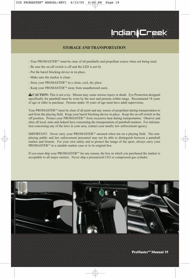
STORAGE AND TRANSPORTATION
- Your PROMASTERTM must be clear of all paintballs and propellant source when not being used.
- Be sure the on-off switch is off and the LED is not lit.
- Put the barrel blocking device in its place.
- Make sure the marker is clean.
- Store your PROMASTERTM in a clean, cool, dry place.
- Keep your PROMASTERTM away from unauthorized users.
CAUTION: This is not a toy. Misuse may cause serious injury or death. Eye Protection designed
specifically for paintball must be worn by the user and persons within range. Recommend 18 years
of age or older to purchase. Persons under 18 years of age must have adult supervision.
Your PROMASTERTM must be clear of all paint and any source of propellant during transportation to
and from the playing field. Keep your barrel blocking device in place. Keep the on-off switch in the
off position. Protect your PROMASTERTM from excessive heat during transportation. Observe and
obey all local, state and federal laws concerning the transportation of paintball markers. For informa-
tion concerning any of the laws in your area, contact your nearby law enforcement agency.
IMPORTANT: Never carry your PROMASTERTM uncased when not on a playing field. The non-
playing public and law enforcement personnel may not be able to distinguish between a paintball
marker and firearm. For your own safety and to protect the image of the sport, always carry your
PROMASTERTM in a suitable marker case or in its original box.
If you must ship your PROMASTERTM for any reason, the box in which you purchased the marker is
acceptable to all major carriers. Never ship a pressurized CO2 or compressed gas cylinder.
ProMasterTM Manual 19
ICD PROMASTER™ MANUAL-REV1 6/15/05 6:06 PM Page 19

20 ProMasterTM Manual
ADJUSTING THE TRIGGER PULL
You will notice three (3) screws in your trigger. These screws adjust the length of pull, actuation point
and spring tension of the trigger. The bottom screw adjusts your trigger stop point (length of pull).
The middle screw is the contact point for your micro switch or actuation point. The top screw is the
spring tension adjustment screw.
1) Place a small drop of blue loctite on the treads of the screws prior to adjusting will help
prevent them from backing out due to normal vibrations created while playing. DO NOT
apply more than a small drop of the loctite to the threads, it can cause damage to the micro
switch if you use too much.
2) Begin by adjusting the bottom screw to your desired pull. Screw it in to lessen the distance
the trigger must travel.
3) Very Carefully screw in the middle screw. Making large adjustments can force the screw into
the micro switch and damage it. You will want to screw it in to the point where it makes
contact with the micro switch but does not permanently rest on it. Continually check to
verify that the LED flashes off and then back on when you pull the trigger. If you pull the
trigger and the LED goes off and stays off, you have adjusted the screw in too far.
back it out.
4) Adjust the spring tension by turning the top screw in for more tension and out for less
tension.
5) Clean up any excess loctite and let it dry for at least an hour before using your
PROMASTERTM. This ensures the screws will remain in place.
20 ProMasterTM Manual
ICD PROMASTER™ MANUAL-REV1 6/15/05 6:06 PM Page 20

ProMasterTM Manual 21
PROMASTERTM TUNING GUIDE
Velocity Adjustment - Using the Main Input Pressure Regulator:
The PROMASTERTM operates on a proven and innovative system. Take the time to understand this
section. The pressurized gas is regulated internally. The high-pressure air is used to propel the
paintball. The low-pressure air is used to operate the 4-way solenoid valve located in the rear of the
marker. The high-pressure regulator is externally adjustable via the screw on the bottom of the
high-pressure regulator (inline regulator). A 5/32 hex key for this screw has been provided to adjust
this screw. To increase the pressure, turn the screw clockwise.
NOTE: Only slight turns are needed to accomplish changes in the pressure used to shoot the paintball.
To decrease the pressure shown on the gauge, turn the screw counter-clockwise. You must take a
clearing shot before the change in the decreasing direction can be registered.
A pressure gauge has been installed into the regulator body to indicate the exact operating pressure of
the marker. This gauge is extremely useful. The regulator is set at the factory to provide an output
pressure of 250-300 PSI with an input pressure of 500 PSI using Compressed air as the base
propellant. Under normal circumstances these settings will produce paintball velocities of
approximately 280-300 fps. The input pressure from your propellant source should be set at 450-500
PSI. Higher input pressures will not provide increased performance. There is a specific input side
and output side of the main input regulator. If the gauge and input sides are switched, the result will
be the main input regulator is totally bypassed.
ProMasterTM Manual 21
ICD PROMASTER™ MANUAL-REV1 6/15/05 6:07 PM Page 21

22 ProMasterTM Manual
LOW PRESSURE REGULATOR ADJUSTMENT
Low Pressure Regulator Adjustment:
The low-pressure regulator is externally adjustable via the adjustment screw in the front of the low-
pressure regulator. The low-pressure regulator is pre-set at the factory to 85-95 PSI to operate the 4-
way solenoid actuated valve located in the rear of the marker. It may be necessary to re-adjust the low-
pressure regulator from time to time to achieve desired velocities, if you are unable using the Main
Input Pressure Regulator. Bench adjusting the regulator can be done by pressurizing the marker, be
sure the input regulator is set properly, and then turning the adjustment screw inward (clock-wise)
until you hear a leak coming from the 4-way valve in the grip area. The 4-way valve has an over-pres-
surization relief valve that will start to bleed off at approximately 125 PSI, once you hear the leak start
then back off the adjustment screw 1/2 turn and the leak will stop. That will approximate the pres-
sure to about 90 PSI. The low-pressure regulator is designed to shut down and preserve the integrity
of the low pressure system if it sees an input pressure over approximately 400 PSI coming from the
main input regulator.
This marker was designed with safety in mind. If you attempt to shoot paintballs higher than estab-
lished safety standards, the marker may not function properly.
***Replacing or removing the original regulators voids all warranties.***
NOTE: NEVER DISASSEMBLE THE SOLENOID VALVE. THIS WILL PERMANENTLYDAMAGE IT BY DISRUPTING THE MAGNETIC FIELD AND WILL VOID YOUR WARRANTY.
22 ProMasterTM Manual
ICD PROMASTER™ MANUAL-REV1 6/15/05 6:07 PM Page 22

ProMasterTM Manual 23
\TROUBLE SHOOTING GUIDE
Leak related problems
1) The PROMASTER™ has a leak down the barrel.
Reason: Gas is leaking through or around the valve pin seal or O-ring area.
a) Can you hear the leak when the gas is removed? Yes? There is no leak. You hear the ocean.
b) The valve seal is marred, scratched, worn out, or dirty. Try cleaning it with rubbing alcohol. If this does not work, replace it.
c) Replace the O-ring around the valve seat.
2) The PROMASTER™ has a leak around the low-pressure regulator seam.
Reason: The seal between the regulator body and regulator adapter body is bad, or the regulator is loose.
a) Tighten the regulator to the body.b) Replace the O-ring on the low-pressure regulator body.
3) The PROMASTER™ has a leak around the high-pressure regulator seam.
Reason: The seal between the regulator body and ASA adapter is bad, or the regulator is loose.
a) Tighten the regulator to the adapterb) Replace the urethane O-ring on the high-pressure regulator body.
4) The PROMASTER™ has a leak inside the grip/battery area.
Reason: The solenoid valve or internal hose is leaking.
a) Check for over-pressurization from the low-pressure regulator. Re-adjust the low-pressure regulator per instructions on the previous pages.
b) Tighten the solenoid to the manifold. Take care not to over-tighten.c) Replace the internal hose if it has visible damage.d) Replace the solenoid valve assembly.
ProMasterTM Manual 23
ICD PROMASTER™ MANUAL-REV1 6/15/05 6:08 PM Page 23

24 ProMasterTM Manual
Ball Breakage Problems
1) The paintballs break in the breech.
a) The paintballs in you loader can bind, messing up your trigger timing. Always use an
agitated or force feed loader and verify the PDS is on.
b) If the paintball retention ball does not move freely, the paintballs will crush against it or it may
have stuck in the depressed position, allowing double feeding. Check its tension regularly and
keep this area as clean as possible.
c) If the paintball retention is too sloppy, the paintballs will not be held in the proper
position. This may allow the next ball to enter the path of the bolt, subjecting it to impact
cracking or shearing. Verify the tension.
Regulator Related Problems
2) The gauge reads correctly when charged, but climbs in pressure after a few moments.
Reason: The high pressure regulator seal has been contaminated.
a) Disassemble the regulator and clean the regulator seal (73) with a Q-tip and alcohol. If you
need assistance in the disassembly of the regulator, please call tech support at
(208) 468-0446.
3) The gauge reads correctly when charged, but drops in pressure after a few shots.
a) The regulator may not be adjusted correctly. Remove all pressurized gas and back out the reg-
ulator adjustment screw until it is flush with the body. Pressurize the system and adjust the
pressure back up to the desired pressure.
b) Verify that the on/off valve on your bottom line adapter is properly adjusted. If the valve is
only partially open, it will restrict air flow into the regulator.
4) The gauge reads correctly when charged, but drops in pressure after a few shots, and is slow to
climb back to normal pressure.
a) The recovery side of the regulator is sluggish and may need cleaning and lubrication. Clean
out any debris and lubricate the urethane O-ring on the outside of the HPR Piston (48) . If you
need assistance in the disassembly of the regulator, please call (208) 468-0446.
b)The regulator seals needs to be replaced if it has a deep groove in it from the regulator cup.
24 ProMasterTM Manual
ICD PROMASTER™ MANUAL-REV1 6/15/05 6:08 PM Page 24

ProMasterTM Manual 25
BATTERY RELATED PROBLEMS
1) LED functions but the marker does not fire.
2) Alternately missed shots.
3) Velocity drops while firing several shots.
4) Erratic velocities. Jumps of 20 fps or more.
5) Unexplainable paint breakage.
6) Slight leak from the solenoid in the back of the grip.
Change the Battery. The LED only requires 1.5 volts to function. The solenoid requires a minimum
of 5 volts to operate. This means the marker may appear to be getting enough power when it is not.
All batteries are NOT created equal. Performance will vary. Therefore, if you experience any
erratic behavior, always change the battery first.
ProMasterTM Manual 25
ICD PROMASTER™ MANUAL-REV1 6/15/05 6:08 PM Page 25

26 ProMasterTM Manual26 ProMasterTM Manual
Part # ICD Item # Description
1 402001 Main Body
2 402012 Bolt
3 D250HCB 1/4 Bolt Chrome Bearing
4 964073 Bolt Retention Spring
5 5162412 5/16-24x1/2 Set Screw
6 402021 Hammer
7 402003 Cylinder Body
8 402019 Piston
9 982071 Cylinder Main Spring
10 17212 1-72x1/2 SHCS
11 H-015 H-015 O-Ring
12 402022 Cylinder End Cap
13 402016 Valve Seat
14 402017 Valve Pin
15 D63388 Valve Seal
16 402018 Valve Cup
17 982073 Valve Spring
18 402009 LP Cup Housing
19 402024 Regulator Cup
20 402008 LP Regulator Body
21 982053 LPR Piston
22 33258 3-32x5/8 Dowel Pin
23 952076 LP Regulator Main Spring
24 402025 LP Adjustment Screw
25 402002 Regulator Mount
26 402013 HP Regulator Top
27 402014 HP Regulator Body
28 982038 HPR Piston
29 992076 HP Regulator Main Spring
30 402031 HP Spring Spacer
31 402015 HP Regulator Bottom
32 402005L Left side of Clamshell Grip
33 402026 Trigger
34 993074 Trigger Spring
35 83214 8-32x1/4 Set Screw
36 83212 8-32x1/2 Set Screw
37 402005R Right Side of Clamshell Grip
38 402030 Ball Detent
Part # ICD Item # Description
39 402007 Eye Holder
40 402006L Left Eye Cover
41 402006R Right Eye Cover
42 63258B 6-32x5/8 Buttonhead
43 103212B 10-32x1/2 Buttonhead
44 103234 10-32x3/4 SHCS
45 402029 Link Pin
46 402011 Feed Tube
47 H-016 H-016 O-Ring
48 H-015UR H-015 UR90 O-Ring
49 H-019 H-019 O-Ring
50 H-020 H-020 O-Ring
51 H-010 H-010 O-Ring
52 H-006 H-006 O-Ring
53 HEA10F5GLD7101W Solenoid
54 63238 6-32x3/8 SHCS
55 63214B 6-32x1/4 Button Head
56 63214S 6-32x1/4 SHCS
57 82414 3-8/24x1/4 Set Screw
58 935075 Regulator Cup Spring
59 935075 Anti-Double Feed Spring
60 PMCB01R Circuit Board
61 BBD Barrel Plug
62 402027 Cylinder Spring Assist Sleeve
63 402028 Cylinder Spring Guide
64 Dwrap Rubber Grip
65 D700LPG 700 p.s.i. Gauge
66 402010 Barrel
67 10/32Barb 10/32 Barb
68 QEV QEV
69 90Barb 90 Degree 3 MM Barb
70 3MMBarb 3 Millimeter Barb
71 10SM007 On/Off Switch
72 348316 3/48x3/16 Pan Head
Phillips Machine Screw
73 D63389 Regulator Seal
74 17238 1-72x3/8 SHCS
ICD PROMASTER™ MANUAL-REV1 6/15/05 6:08 PM Page 26