2004 international workshop on wireless ad-hoc networks a
TRANSCRIPT

2004 International Workshop on Wireless Ad-Hoc Networks
A Joint MIMO-OFDM Transceiver and MAC Design for Mobile Ad Hoc Networking
Taiwen Tang, Minyoung Park, Robert W, Heath, Jr. and Scott M. NettIes Department of Electrical & Computer Engineering,
The University of Texas at Austin, Austin, TX 78712-0240, Email: [email protected], [email protected], [email protected], [email protected]
Abslracl-In this paper, we present a prodsing joint design of a physical layer transceiver architecture and a medium access controI (MAC) protocol for multiple-input mu1 tiple-output (MIMO) orthogonal frequency division multiplexing (OFDM) ad hoc networks. The receiver design is based on a new space- time interference cancelling technique for MIMO-OFDM ad hoc networks which suppresses co-channel interference and jammers, separala out multiple data streams, and minimizes inter-carrier interference (ICI). We take a cross layer approach to design the medium access control (MAC) protocol to fully exploit the advantages of the physical layer transceiver architecture. The MAC protoCO1 is the recently developed medium access control protocol - Mitigating Interference using Multiple Antennas MAC (MIMA-MAC). It takes the advantage of the ability of MIMO-OFDM to demodulate multiple data streams to solve a key problem of 802.11-style MACS. Joint physical and higher layer simulations confirm that our joint design experiences good performance in terms of BER and MAC throughput and fairness.
I . INTRODUCTION Mobile ad hoc wireless networks are decentralized self-
organizing wireless communication networks that do not re- quire a fixed infrastructure. They generally have the ability to self-configure and thus C M quickly respond to loss of nodes, changes in network topology, and link fluctuations due to fading and interference. While ad hoc networks provide the network robustness required in the wireless battlefield environment, limitations due to fading from the multi-path channel, collisions from other nodes in the network, and jam- ming from hostile interferers, unfortunately, limit the overall network capacity.
One approach for improving the link and system capacity of an ad hoc network is through the use of multiple transmit and receive antennas configured to create multiple-input multiple- output (MIMO) communication channels. There has recently been increased attention in ad hoc networks empIoying di- rectional antennas, smart antenna arrays, and more recently MIMO technology. Fully exploiting MEMO capability in a mobile ad hoc network requires a flexible physical layer to provide various modes of operation to exploit the diversity and capacity advantages as well as a MAC protocol that can efficiently choose from the multitude of modes of operation.
In this paper we review a promising joint design of physical layer system architecture and MAC protocol for broadband MZMO ad hoc networks. The physical layer system is built on MIMO-OFDM modulation, which combines the capacity
benefits of MIMO with the IOW complexity equalization prop- erty of OFDM (orthogonal frequency division multiplexing). A novel space-time / space-frequency interference cancelling receiver is adopted to suppress co-channel interference (CCI j, separate multiple data streams, compensate for asynchronicity between different users, and suppress intercanier interference (ICI) through channel shortening [l]. Compared with prior work [Z], [3], our scheme estimates the space-time equalizer coefficients, the equalization decision delays, and the post equalization channel directly from the training data [I].
The MAC solution uses the Mitigating Interference us- ing Multiple Antennas MAC (MIMA-MAC) protocol, first proposed in [4]. It exploits the flexibility introduced at the physical layer to improve the performance not simply by im- proving the performance of a link but by solving the problems of a conventional carrier sense multiple access with colli- sion avoidance ( C S W C A j and request-to-send/clear-to-send (RTSKTS) handshaking based MAC protocol. Using the IEEE 802.11 MAC protocol [SI in the Distributed Coordination Function (DCF) mode for multi-hop ad hoc networks incurs two problems: unfairness between the neighboring traffic flows and degradation of throughput [6] , [7]. These problems arise. because several transmissions cannot occur simultaneously. The MIMA-MAC protocol takes advantage of our MIMO- OFDMs receiver’s ability to separate multipIe data 5treams to solve this problem. Our previous work on MIMA-MAC [4] assumed only a narrowband MA40 physical layer and was not customized for our broadband MIMO-OFDM receiver [l]. Crass-layer simulation shows that our proposed MAC protocol improves the system throughput and fairness compared with an 802.1 I-style MAC using the same physical layer techniques.
11. MIMO-OFDM AD Hoc DESIGN REVIEW
MIMO-OFDM ad hoc networks face various challenges at both the physical and MAC layer, In this section, we review a joint design of the physical layer transceiver architecture and MAC protocol to tackle these problems. A MAC level solution, which utilizes physical layer interference cancellation functionality, is proposed to solve the problems inherent to 802.11 -style MACS, and a MIMO-OFDM transceiver design that supports simultaneous communications needed by the MAC is discussed.
0-7803-8275-7/0~$20.00 0 2004 IEEE 31 5
e
........ : .......
. . . .
....
7 0 0
w.11 w*k.n.r~l 0 m.11 s w m r ~ . T $ ~ _ . . . . . . . . . . . . . . . . . . . . . . . . . . . . . . . . . . .
r
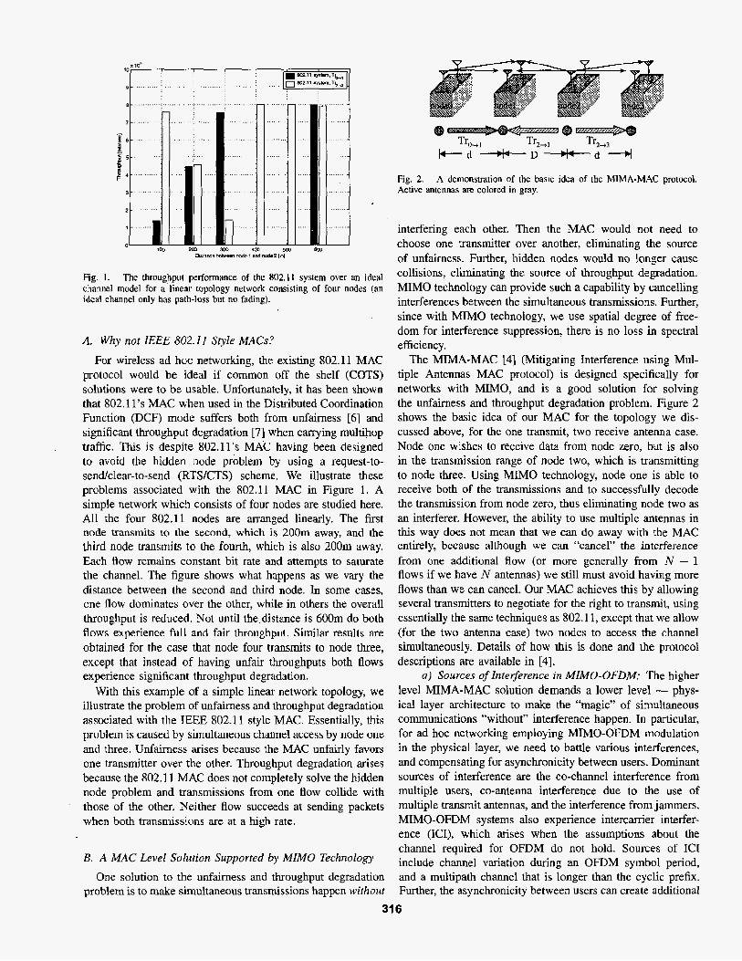
Fig. 1. The throughput performance of the 802. I I system over an ideal channel model for a linear topology network consisting of four nodes (an ideal channel only has path-lass but no fading).
A. Why not lEEE 802.1 I Style MACS?
For wireless ad hoc networking, the existing 802.11 MAC protocol would be ideal if common off the shelf (COTS) solutions were to be usable. Unfortunately, it has been shown that 802.11’s MAC when used in the Distributed Coordination Function (DCF) mode suffers both from unfairness [6] and significant throughput degradation [7] when carrying multihop traffic. This is despite 802.11’s MAC having been designed to avoid the hidden node problem by using a request-to- sendlclear-to-send (RTSKTS) scheme, We illustrate these problems associated with the 802.11 MAC in Figure 1. A simple network which consists of four nodes are studied here. All the four 802.11 nodes are arranged linearly. The first node transmits to the second, which is 200m away, and the third node transmits to the fourth, which is also 200m away. Each flow remains constant bit rate and attempts to saturate the channel. The figure shows what happens as we vary the distance between the second and third node. In some cases, one flow dominates over the other, while in others the overall throughput is reduced. Not until the.distance is 6OOm do both flows experience full and fair throughput. Similar results are obtained for the case that node four transmits to node three, except that instead of having unfair throughputs both flows experience significant throughput degradation.
With this example of a simple linear network topology, we illustrate the problem of unfairness and throughput degradation associated with the E E E 802.1 1 style MAC. Essentially, this problem is caused by simultaneous channel access by node one and three. Unfairness arises because the MAC unfairly favors one transmitter over the other. Throughput degradation arises because the 802.1 1 MAC does not completely solve the hidden node problem and transmissions from one flow collide with those of the other. Neither Aow succeeds at sending packets when both transmissions are at a high rate.
B. A MAC Level Solution Supported by MIMO Technology
One solution to the unfairness and throughput degradation problem is to make simultaneous transmissions happen wilhoul
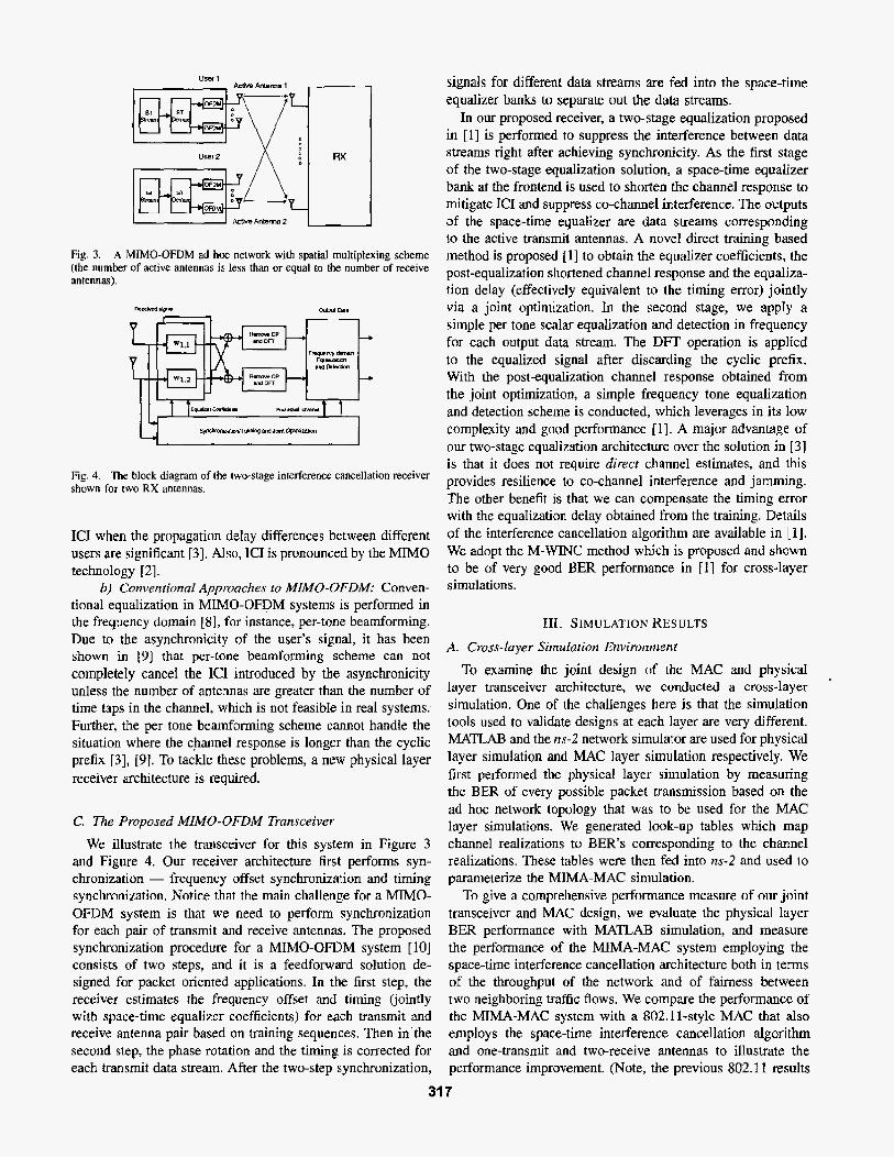
Fig. 2. Active antennas are colored in gray.
A demonstration of the basic idea of the MIMA-MAC protocol.
interfering each other. Then the MAC would not need to choose one transmitter over another, eliminating the source of unfairness. Further, hidden nodes would no longer cause collisions, eliminating the source of throughput degradation. MIMO technology can provide such a capability by cancelling interferences between the simultaneous transmissions. Further, since with MIMO technology, we use spatial degree of free- dom for interference suppression, there is no loss in spectral efficiency,
The MIMA-MAC [4] (Mitigating Interference using Mul- tiple Antennas MAC protocol) is designed specifically for networks with MMO, and is a good solution for solving the unfairness and throughput degradation problem. Figure 2 shows the basic idea of our MAC for the topology we dis- cussed above, for the one transmit, two receive antenna case. Node one wishes to receive data from node zero, but is also in the transmission range of node two, which is transmitting to node three. Using MIMO technology, node one is able to receive both of the transmissions and to successfully decode the transmission from node zero, thus eliminating node two as an interferer. However, the ability to use multiple antennas in this way does not mean that we can do away with the MAC entirely, because although we can “cancel” the interference from one additional flow (or more generally from N - 1 flows if we have N antennas) we still must avoid having more flows than we can cancel. Our MAC achieves this by allowing several transmitters to negotiate for the right to transmit, using essentially the same techniques as 802.1 1, except that we allow (for the two antenna case) two nodes to access the channel simultaneously. Details of how this is done and the protocol descriptions are available in [4].
a) Sources of Interference in MIMU-OFDM: The higher level MIMA-MAC solution demands a lower level - phys- ical layer architecture to make the “magic” of simultaneous communications “without” interference happen. In particular, for ad hoc networking employing MIMO-OPDM modulation in the physical layer, we need to battle various interferences, and compensating for asynchronicity between users. Dominant sources of interference are the co-channel interference from multiple users, co-antenna interference due to the use of multiple transmit antennas, and the interference from jammers, MIMO-OFDM systems also experience intercanier interfer- ence (ICI), which arises when the assumptions about the channel required for OFDM do not hold. Sources of IC1 include channel variation during an OFDM symbol period, and a muhipath channel that is longer than the cyclic prefix. Further, the asynchronicity between users can create additional
31 6
I I_. 1
User 2 K / \ - 1
RX
Fig. 3. A MIMO-OFDM ad hoc network with spatial multiplexing scheme (the number of active antennas is less than or equal to the number of receive antennas).
Fig. 4. The block diagram of h e two-stage interference cancellation receiver shown for two RX antennas.
IC1 when the propagation delay differences between different users are significant [3]. Also, IC1 is pronounced by the MIMO technology [2].
6) Conventional Approaches to MIMU-UFDM: Conven- tional equalization in MIMO-OFDM systems is performed in the frequency domain [8], for instance, per-tone beamfonning. Due to the asynchronicity of the user’s signal, it has been shown in 19) that per-tone beamforming scheme can not completely canceI the IC1 introduced by the asynchronicity unless the number of antennas are greater than the number of time taps in the channel, which is not feasible in real systems: Further, the per cone beamforming scheme cannot handle the situation where the channel response is longer than the cyclic prefix [3], [9]. To tackle these problems, a new physical layer receiver architecture is required.
C. The Proposed MIMO-UFDM Transceiver
We illustrate the transceiver for this system in Figure 3 and Figure 4. Our receiver architecture first performs syn- chronization - frequency offset synchronization and timing synchronization. Notice that the main challenge for a MIMO- OFDM system is that we need to perform synchronization for each pair of transmit and receive antennas. The proposed synchronization procedure for a MIMO-OFDM system [lo] consists of two steps, and it is a feedforward solution de- signed for packet oriented applications. In the first step, the receiver estimates the frequency offset and timing Cjointly with space-time equalizer coefficients) for each transmit and receive antenna pair based on training sequences. Then in’the second step, the phase rotation and the timing is corrected for each transmit data stream. After the two-step synchronization,
signals for different data streams are fed into the space-time equalizer banks to separate out the data streams.
In our proposed receiver, a two-stage equalization proposed in [I] is performed to suppress the interference between data streams right after achieving synchronicity. As the first stage of the two-stage equalization solution, a space-time equalizer bank at the frontend is used to shorten the channel response to mitigate IC1 and suppress co-channel interference. The outputs of the space-time equalizer are data streams corresponding to the active t ransmi t antennas. A novel direct training based method is proposed [l] to obtain the equalizer coefficients, the post-equalization shortened channel response and the equaliza- tion delay (effectively equivalent to the timing error) jointly via a joint optimization. In the second stage, we appIy a simple per tone scalar equalization and detection in frequency for each output data stream. The DFT operation is applied to the equalized signal after discarding the cyclic prefix, With the post-equalization channel response obtained from the joint optimization, a simple frequency tone equalization and detection scheme is conducted, which leverages in its low complexity and good performance [I]. A major advantage of our two-stage equalization architecture over the solution in [3J is that it does not require direcr channel estimates, and this provides resilience to co-channel interference and jamming. The other benefit is that we can compensate the timing error with the equalization delay obtained from the training. Details of the interference cancellation algorithm are available in [I]. We adopt the M-WINC method which is proposed and shown to be of very good BER performance in [ I ] for cross-layer simulations.
111. SIMULATION RESULTS A. Cross-layer Siinularion Enviroiiment
To examine the joint design of the MAC and physical layer transceiver architecture, we conducted a cross-layer simulation. One of the challenges here is that the simulation tools used to validate designs at each layer are very different. MATLAB and the ns-2 network simulator are used for physical layer simulation and MAC layer simulation respectively. We first performed the physical layer simulation by measuring the BER of every possible packet transmission based on the ad hoc network topology that was to be used for the MAC layer simulations. We generated look-up tables which map channel realizations to BER’s corresponding to the channel realizations. These tables were then fed into ns-2 and used to parameterize tbe MIMA-MAC simulation.
To give a comprehensive performance measure of our joint transceiver and MAC design, we evaluate the physical layer BER performance with MATLAB simulation, and measure the performance of the MIMA-MAC system employing the space-time interference cancellation architecture both in terms of the throughput of the network and of fairness between two neighboring traffic flows. We compare the performance of the MIMA-MAC system with a 802.11-style MAC that also employs the space-time interference cancellation algorithm and one-transmit and two-receive antennas to illustrate the performance improvement. (Note, the previous 802.1 1 results
31 7

presented in Section I1 were based on the actual EEE 802.1 1 b physical layer.)
B. Simulation Setup
a) Network configuration: A linear topology network consisting of four nodes with two antennas as shown in Figure 2 is used for cross-layer simulation. TO simplify the connection with the physical layer simulation, relative dis- tances between nodes instead of absolute distances are used here. The distance between node 0 and node 1 and between node 2 and node 3 is fixed to be one unit distance, d = 1. By varying the distance between the receiver (node 1) and neighboring transmitter (node 2), D, from 0.5 to 3, we measure the system performance as the distance increases.
bJ Trufic model: To evaluate the MAC throughput and fairness, we use two constant-bit-rate (CBR) traffic flows, one from node 0 to node 1, Tro-1, and the other from node 2 to node 3, Tr2-3. The rate of each flow consumes the full channel resource in time and frequency, but we adopt MIMO technology for interference cancellation.
c) Physical layer; The training based algorithm for the space-time interference cancellation architecture is the M- WINC proposed in [l]. The carrier frequency, the frequency bandwidth and the data rate are set to 2.4GHz, 2MHz and lMbps, respectively. The propagation delay is proportional to the distance between nodes. The path-loss exponent is set to 4 assuming that the distance between transmitter and receiver is sufficiently large [ l l ] . We fix the input SNR to be 12dEi. We set the packet reception threshold BER and the carrier sensing threshold BER to and lo-', respectively. Successful packet reception or carrier sensing is identified if the BER is below the corresponding threshold.
The physical layer setup is the MIMO-OFDM modula- tion employing QPSK and 128 frequency tones per OFDM symbol. We set the cyclic prefix length to be 16. A block fading model is adopted in the simulation, i.e., the channel is assumed to be fixed over a frame which contains certain number of OFDM blocks, but for each frame, the channel has a different realization. Each coefficient of the discrete- time sampled impulse response is generated according to a complex Gaussian distribution with zero mean and the variance inversely proportional to the path-loss. Each tap is uncorrelated in space and time. For each channel realization, only one OFDM block is needed for the equalizer training, and random training sequences are generated for equalizer training. In the training stage, the equalizer coefficients and the post-equalization channel response can be obtained via the joint optimization. After the training stage, we apply the equalizer obtained at the training stage to equalize the received signal. To enhance the bit error rate performance, we adopt convolutional coding with generator polynomial (133,171) and the IEEE 802.11a interleaving scheme across OFDM tones in the simulation. We apply the equal power allocation scheme across all OFDM tones for data transmission. Also notice that since the spatial multiplexing scheme is adopted, there is no interleaving in space. At the receiver, soft Viterbi decoding is applied for convolutional decoding. We calculate
*
10
10
10
I 10
lo-'
I 4 6 a i o 12 14 i s
SRR ga)
Fig. 5 . A plot of BER vs. SNR averaged over 400 channel realizations with fixed equalizer memory length L = 12. The channel taps for the links 0 4 I and 2 4 1 are both 6. The delay of link 2 -+ 1 is proportional to D / d .
the soft decoding metrics by the Euclidean distances for each frequency tone. The details can be found in [l].
C. Physical Layer Simulation Results
With the given traffic Bow model, we study the BER performance of the traffic flow 0 4 1 in the presence of co- channel interference from the traffic flow from 2 4 3. Figure 5 illustrates the average BER performance (averaged over 400 channel realizations) of the link between 0 and 1 for different distances between node 2 and 1, varying from 0.5 to 3. Since the interference power decreases with the 4th power of the distance between node 1 and 2, and the propagation delay of flow 2 to 1 increases linearly with the distance, the BER performance is improved as the distance between node 1 and 2 increases. For 12 dB input SNR, the average BER is on the order of lop5 even for the case of D / d = 0.5.
D. MAC Layer Performance Evaluation
The total throughput of the network is measured in bits/sec and fairness between the two traffic flows is measured using the fairness-ratio (FR), which is defined as F R = 1 -
where Tho-1 and Th2-3 denote the through- put of Tro-1 and Tr2-3, respectively. When two traffic flows are perfectly fait, FR becomes 1, whereas if the two traffic flows are extremely unfair, FX approaches 0.
Figure 6 shows the performance of both the MIMA-MAC system and the 802.1 1-style system. In both graphs, the X-axis is the ratio of D to d. The Y-axis of the throughput graph is throughput in bitskec and of the fairness graph, the fairness ratio.
For the MIMA-MAC system, we see that for both flows the throughput is high and thus the fairness ratio is near one no matter what the distance between node 1 and node 2. This is because node 1 can mitigate interference from node 2 using the space-time interference cancellation algorithm and because MIMA-MAC takes advantage of this by not forcing one transmitter or the other to be silent to avoid such interference. The results show a slight throughput increase as we increase
1ThO-1 -Th2+31 ThCl--l+Th2+3
31 8

:[Lm 8 ..... . I . . :... .... ... . ....
5 0.5 1 1.5 2 2.5 3 DkS- rW0 Wd
(a) Throughput performance
. . . . . . . . .
S a s 1 1 5 2 25 3 5 5 aslar-m“
(b) Fairness-ratio perfomarm
Fig. 6. Throughput and faimess comparison between the MIMA-MAC system and the 802.11 system using the space-time interference cancellation algorithm in the physical layer. The transmitters use one antenna and the receivers use two antennas.
D due to the decreased interference between the two traffic flows. T~2-3 shows slightly higher throughput than Tro-1 because node 1 experiences more interference than node 3. In contrast, the 802.1 1-style system experiences extreme
unfairness when the two traffic flows are close enough to affect each other’s communication. We observe extreme unfairness in figure 6 when Dld = 1 and 2. When D/d = 1, node 2 has perfect knowledge of Tro-1 by overhearing the CTS from node 1, whereas node 0 does not have correct information since node 2 is too far from node 0 for it to hear the CTS. The different level of information of each other’s communication results in node 2 k i n g able to monopolize the channel. When D/d = 2, neither traffic source can receive the other’s transmission but one of the traffic sources (node 2), can still interfere with the receiver (node 1) of the other traffic flow. Since, node 3 is far from the possible interferer, node 0, the transmission from node 2 io node 3 achieves high throughput whereas the transmission from node 0 to node 1 experiences severe interference from node 2, which results in most of its packets being lost to collisions. This illustrates the failure of 802.1 1-style MACS to fully solve the hidden node problem. When the two traffic flows are close enough (Did = O.S), both traffic sources have the same information about each other’s communication in the network, which provides i t certain level of fairness, but throughput is reduced because of the need to share the channel.
Finally, when the two traffic flows are far enough apart (D/d = 3), they are separated and do not interfere each other’s communication, which naturally guarantees fairness and max- imizes throughput. The simulation illustrates that even when used with our MIMO-OFDM physical layer, the 802.1 I-style MAC performs poorly. To achieve maximum performance, it is crucial that the MAC take full advantage of the sophisticated MIMO physical layer.
Iv. CONCLUSlONS
In this paper, we presented a joint design of a physical layer transceiver architecture and a MAC protocol for a MIMO-OFDM ad hoc network. The joint design combines the advantage of the interference cancellation receiver architecture proposed in [l] and the MIMA-MAC protocol in [4]. Cross- layer simulations were conducted to evaluate the system performance. Very good BER performance offered by the MIMO-OFDM receiver design is observed in the simulation. With the MIMA-MAC utilizing the reliable physical layer transceiver architecture, significant improvement in terms of MAC throughput and fairness is achieved compared to the 802.1 1 style MAC in the cross-layer simulation.
ACKNOWLEDGMENT
This material is based in part upon work supported by the Texas Advanced Technology Program under Grant Nos. 003658-0614-2001 and 003658-0380-2003 and by the Na- tional Science Foundation under grant number EIA-0322957.
REFERENCES T. Tang and R. W. Heath, Jr., “A direct training-based method for space- time interference cancellaljon equalizer design in MIMO-OFDM sys- tems,” submitted to IEEE Glob. Teleconr. CorG 2004.. [Online]. Avail- able: http:/ lwww.ece.utexas.edu/~r~eat~pa~rs/ZO~/glo~com~l/ . A. Stamoulis, S. N . Diggavi, and-N. AI-Dhahir, “Intercanier interference in MIMO OFDM,” IEEE Truns. on Sig. Pmc., vol. 50, no. 10, pp. 2451- 2464, Oct. 2002. M. B. Breinholt. M. D. Zoltowski, and T. A. Thomas, “Space-time equalization and interference cancellation for MIMO-OFDM,” in Pmc. ojlhe A d . Conj on Sig Sys. and Comp., NOV. 2002, vol. 2, pp. 1688- 1693. M. Park, S.-H. Choi. and S. M. Nettles, “Improving Fairness and Throughput for Ad Hoc Networks Using Multiple Anten- nas,” submitted to Pruc. ACM Mubidom 2004., [Online]. Avaitable: http://webspace.utexas.edu/parkm 1 I /paper. Wireless IAN Medium Access Corilrvl (MAC) and Physical Loyer ( P H Y ) Specijicarion, IEEE Std. 802.1 I . 1997. S. Xu and T. Saadawi. “Does the IEEE 802.1 1 MAC Protocol Work Well in Multihop Wireless Ad Hoc Networks?,” IEEE Commun. Mag.+ vol. 39, no. 6, pp. 13&137, June 2001. K. Xu, M. Gerla, and S. Bae, “How Effective is the IEEE 802:il RTSKTS Handshake in Ad Hoc Networks?,” i n Pmc. IEEE Glubecom, Taipei, Taiwan, R.O.C., Nov. 2002, pp. 17-21. G. L. Stuber, J. R. Barry, S. W. Mclaughlin. Y. G. Li, M. A. Ingram, and T. G. Pratt, “Broadband MIMO-OFDM wireless communications,” in Proceedings of rbe IEEE, Feb. 2004, vol. 92, pp. 271 - 294. T. A. Thomas and E W. Vook, “Asynchronous interference suppression in broadband cyclic-prefix communications,” in IEEE Wireless Cammu- nicurions and Networking Conference, March 2003, pp. 568-572. T. Tang and R. W. Heath Jr., “Frequency offset estima- tion for mimo frequency selective channels,” To be sub- mitted to l E E E Vehicular Technology Cot$, [Online]. Available: http://www.ece.utexas.edulNrheatNpapers/2004NTC.I/, 2004. T. Rappaport. Wireless Communicoriuns: Principles and Practice. PrPntice Hall, second edition, 1996.
319