2004 capstone cdr team safe members anders fornberg alejandro henriquez shannon lahr aaron lyons...
Post on 21-Dec-2015
213 views
TRANSCRIPT

2004 CAPSTONE CDR2004 CAPSTONE CDR
Team SAFE Members Anders Fornberg Alejandro Henriquez Shannon Lahr Aaron Lyons Sean Groves
Shannon

Presentation OverviewPresentation Overview
Project Overview System Specification Subsystem Design
Processor & FPGA Power & Structures Sensors & Motors
Current Status and Project Goals
Shannon

Project DescriptionProject Description
• Modified RC car that can sense an accident threat and take corrective action
• Detects and Prevents multiple accidents• Head on Collisions• Merging into blind spots• Backing into Stationary Objects
Shannon

Modes of Operation 3 Modes of operation 1) User has complete control of the RC car.
2) Primary: SAFE System provides audible warning when an accident is immanent. If corrective action is not taken than Safe System takes control.
3) When accident is immanent, SAFE System takes immediate action and assumes control from the user.
Shannon
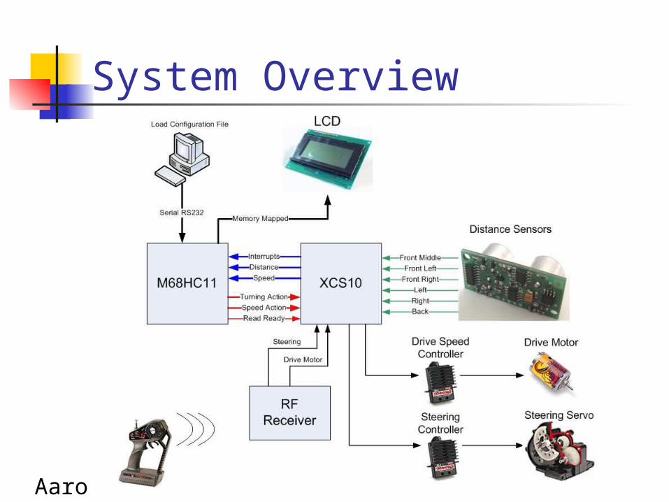
System Overview
Aaron

Interface Specification
Aaron

Interrupt Type
Aaron

Current Speed
Aaron
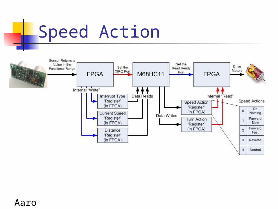
Speed Action
Aaron

Turn Action
Aaron
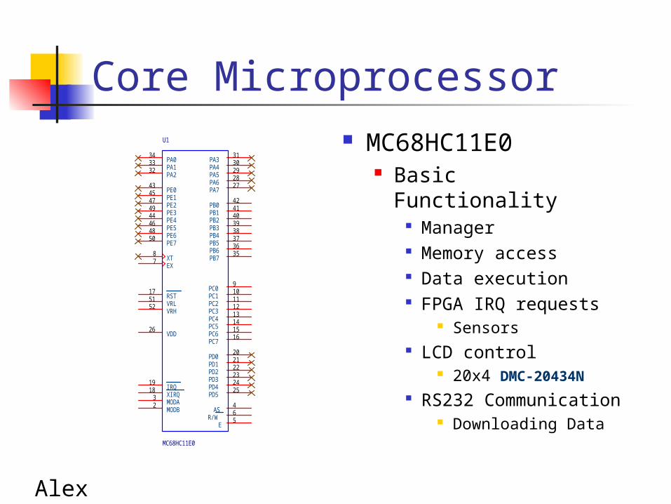
Core Microprocessor MC68HC11E0
Basic Functionality Manager Memory access Data execution FPGA IRQ requests
Sensors LCD control
20x4 DMC-20434N RS232
Communication Downloading Data
VRH52 VRL51
PA331
PA430
PA529
PA628
PA727
PB042
PB141
PB240
PB339
PB438
PB537
PB636
PB735
PC09
PC110
PC211
PC312
PC413
PC514
PC615
PC716
PD020
PD121
PD222
PD323
PD424
PD525
E5
VDD26
XT8
EX7
RST17
IRQ19
XIRQ18
MODB2
PA034
PA133
PA232
PE043
PE145
PE247
PE349
PE444
PE546
PE648
PE750
AS4MODA
3
R/W6
U1
MC68HC11E0
Alex

FPGA XCS10
Basic Functionality Work Horse Read Sensors Chip Select
Send Interrupts (XIRQ) Provide HC11 with:
Interrupt reg. Speed reg. Distance reg.
Receive Data from HC11 Speed Action reg. Turn Action reg.
Interrupt car control Speed Controller Steering Controller
PROGRAM55
CCLK73
I/O70
SGCK1(I/O)A1510
SGCK2(I/O)29
SGCK3(I/O)51
SGCK4(I/O)DOUT72
PGCK1(I/O)A1613
PGCK2(I/O)35
PGCK3(I/O)57
PGCK4(I/O)A178
TDI(I/O)15
TDO(I/O)75
TMS(I/O)17
TCK(I/O)16
MODE32
NC30
NC34
DIN(I/O)71
I/O69I/O67I/O65I/O61I/O59I/O58I/O56
HDC36
LDC(I/O)37
INIT(I/O)41DONE53
I/O60
(I/O)CS1/A279
(I/O)WS/AO77
I/O66
(I/O)A1714
I/O26
I/O18
I/O19
I/O20
I/O23
I/O24
I/O25
I/O27
I/O28
I/O38
I/O39
I/O40
I/O44
I/O45
I/O46
I/O47
I/O48
I/O49
I/O50
I/O62
I/O68
(I/O)A380
(I/O)A481
(I/O)A582
(I/O)A683
(I/O)A784
(I/O)A83
(I/O)A94
(I/O)A105
(I/O)A116
(I/O)A127
(I/O)A138
(I/O)A149
U31
XCS10/LCC
Alex

Alex

Memory Map
Alex

Power
Shannon

Power Continued
20ft tether to power car during testing
3 9V batteries in parallel for expo 150mAh/battery = 450mAh
Expected mAh of project: Board = 100mA 6 Sensors = 180 mA LCD Screen = 4.5mA Total = Approximately 300mA
Shannon

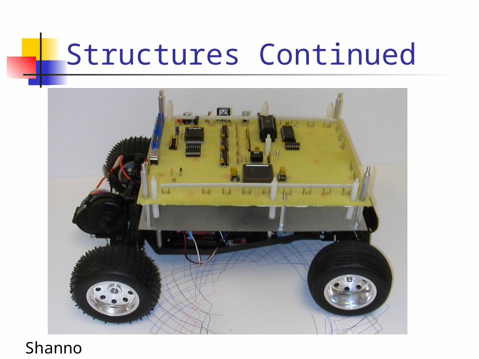
Structures
Shannon

Structures Continued
Shannon
Structures Continued
Shannon

Structures Continued
Shannon
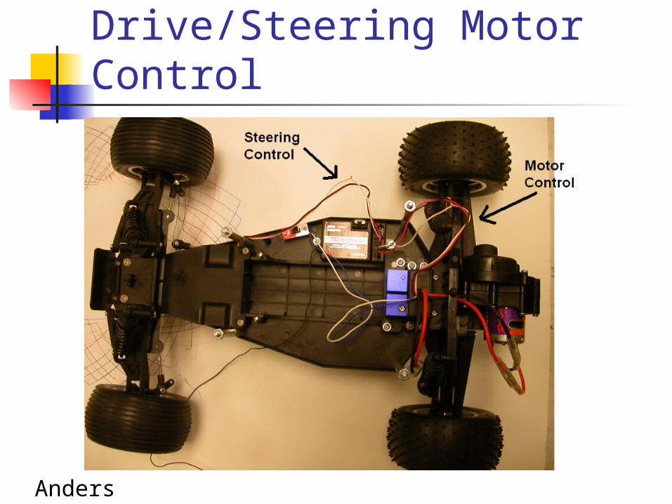
Drive/Steering Motor Control
Anders

Pulse Steering Motor Control
00.5
11.5
2
2.53
3.5
44.5
0 0.5 1 1.5 2 2.5 3 3.5
Time [ms]
Am
pli
tud
e [
V] Straight
Full Left
Full Right
Slow Right
Slow Left
Steering Motor Waveform
Pulse Steering Motor Motor
Burst Rate 20ms
Forward Pulse Width 1.5ms
Max Left 1ms
Max Right 2ms
Slight Left 1.4ms
Slight Right 1.6msAnders

Pulse Drive Motor Control
0
0.5
1
1.5
2
2.5
3
3.5
4
4.5
0 1 2 3 4
Time [ms]
Am
pli
tud
e [
V]
Neutral
Max Forward
Max Reverse
Pulse Drive Motor
Burst Rate 20ms
Neutral PW 1.5ms
Max Forward PW
1ms
Max Reverse PW
2ms
Vmax 4.125
Drive Motor Waveform
Anders

Sensor Package
Problems Encountered•Voltage level would drift for various reason•Highly Dependent on surface tilt and material•Non linear output at large distances•“Sort of” reliable at < 40 inches•Needed use of op-amp, AC to DC, and A-D converter
9 V Sensors
0
100
200
300
400
500
600
700
0 10 20 30 40 50 60 70
Distance [inches]
Ou
tpu
t [m
V]
Anders

Sensor Package SRF04Voltage 5v
Current 30mA Typ. 50mA Max
Maximum Range 3 m
Minimum Range 3 cm
Densitivity Detect a 3cm diameter stick at >2 m
Size 1.75”w x .625”h x .5” d
Anders
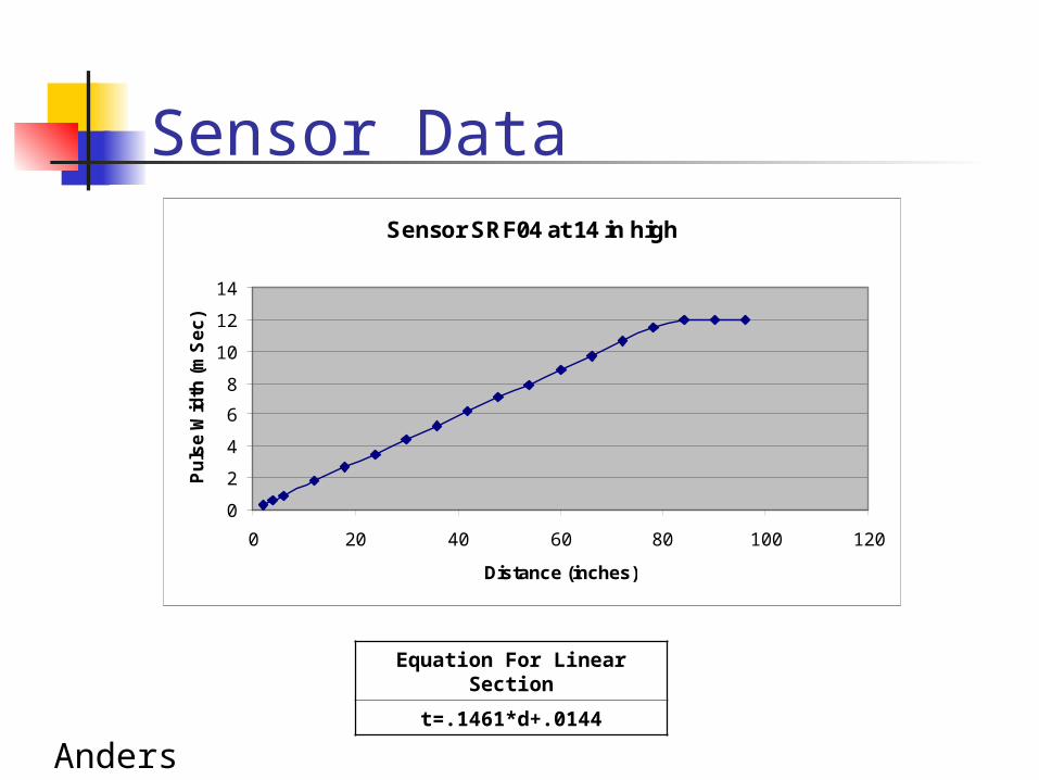
Sensor SRF04 at 14 in high
0
2
4
6
8
10
12
14
0 20 40 60 80 100 120
Distance (inches)
Pu
lse
Wid
th (
mS
ec
)
Sensor Data
Equation For Linear Section
t=.1461*d+.0144
Anders

Sensor Field
Anders

Current Status
Processor and Memory
11 10
74HC14
ADDR4VRH52 VRL51
PA331
PA430
PA529
PA628
PA727
PB042
PB141
PB240
PB339
PB438
PB537
PB636
PB735
PC09
PC110
PC211
PC312
PC413
PC514
PC615
PC716
PD020
PD121
PD222
PD323
PD424
PD525
E5
VDD26
XT8
EX7
RST17
IRQ19
XIRQ18
MODB2
PA034
PA133
PA232
PE043
PE145
PE247
PE349
PE444
PE546
PE648
PE750
AS4MODA
3
R/W6
U1
MC68HC11E0
ADDR5
11 10
74HC14
ADDR6VCC
ADDR1
ADDR2ADDR3
ADDR7
VCC
ADDR1
/E
ADDR6
DIR1
A89
B811B712B613B514B415B316B217B118
G19
VCC20
A12
A23
A34
A45
A56
A67
A78
U27
MM74HC245A
VCC
VCC
D011
D112
D213
D315
A117
A84
A139 A128
A106
A021
A123
A224
A325
A426
A51
A62
A73
A95
A1410
D416
D517
D618
D719
VCC28
OE22
WE27
CE20
U34
CY62256
A9A8
A11A10
A14A13A12
A15
1K
1uF
ADDR12
ADDR14ADDR13
D1D0
D2
OUT5
Y1
OSC8
D3D4
8Mhz
D5
R15RES
D6D7
D0D1D2
ADDR5
ADDR7
D3D4
ADDR11
D5D6
ADDR8
D7
D0
VCC
ADDR9
D1
ADDR10
Decoupleing Caps needed
ADDR11ADDR12
D2
ADDR0
ADDR13ADDR14
ADDR10
ADDR15
D3
1
2
SW2
SW TACT-SPST-2
DATA0
D1 R1
C1
3 4
U24B
74HC14
5 6
U24C
74HC14
RESET SWITCH
From Xilinx Page
4
56
U11B
74HC08
VCC
DONE
DATA1
ADDR4
D4
DATA2
11 10
74HC14
WE1
GN
D14
CE20
OE22
VCC28
I/O011
I/O112
I/O213
I/O315
I/O416
I/O517
I/O618
I/O719
A010
A19
A28
A37
A46
A55
A64
A73
A825
A924
A1021
A1123
A122
A1326
A1427
U37
AT28LV256
DATA3
ADDR15
ADDR9
ADDR[0:15]
D03
D14
D27
D38
D413
D514
D617
D718
OE1 LE
11
Q02
Q15
Q26
Q39
Q412
Q515
Q616
Q719
U26
CD74HC373
DATA4
ADDR8
D5 DATA5
DIR1
A89
B811B712B613B514B415B316B217B118
G19
VCC20
A12
A23
A34
A45
A56
A67
A78
U23
MM74HC245A
DATA6DATA7
D6
ADDR0
4.7K SIP
VCC
ADDR2
VCC
D7
ADDR3
Sean

Processor and Memory
Wired and tested Runs Code from EPROM Fully functional RAM
Serial Port Construction New clock
Sean

Current Status
FPGA and EPROM
DONE
VCC
To processor and memory page
300 ohm
VCC
4.7K
PROGRAM55
CCLK73
I/O70
SGCK1(I/O)A1510
SGCK2(I/O)29
SGCK3(I/O)51
SGCK4(I/O)DOUT72
PGCK1(I/O)A1613
PGCK2(I/O)35
PGCK3(I/O)57
PGCK4(I/O)A178
TDI(I/O)15
TDO(I/O)75
TMS(I/O)17
TCK(I/O)16
MODE32
NC30
NC34
DIN(I/O)71
I/O69I/O67I/O65I/O61I/O59I/O58I/O56
HDC36
LDC(I/O)37
INIT(I/O)41DONE53
I/O60
(I/O)CS1/A279
(I/O)WS/AO77
I/O66
(I/O)A1714
I/O26
I/O18
I/O19
I/O20
I/O23
I/O24
I/O25
I/O27
I/O28
I/O38
I/O39
I/O40
I/O44
I/O45
I/O46
I/O47
I/O48
I/O49
I/O50
I/O62
I/O68
(I/O)A380
(I/O)A481
(I/O)A582
(I/O)A683
(I/O)A784
(I/O)A83
(I/O)A94
(I/O)A105
(I/O)A116
(I/O)A127
(I/O)A138
(I/O)A149
U31
XCS10/LCC
GND6
TDI1
TMS2
TCK3
TDO4
VCC5
JTAG Conn.
VCC33
Data
(DO
)1
D69
GND
11
D712
CEO
bar
13
D514D315D116TD017VCC18VC
CO19
VCC
20
D22
CLK
3
TDI4
TMS5
TCK6
D4/CFbar7
OE/RESETbar8
CEba
r10
U29
XC18V256
VCC
Sean

FPGA and EPROM
Sean
001
111

Problems Encountered
Learning Curve Wire-wrap Issues B-scan for FPGA Xilinx project navigator link to
Impact Power-Ground Short Inaccurate Part Specifications Labeling
Sean
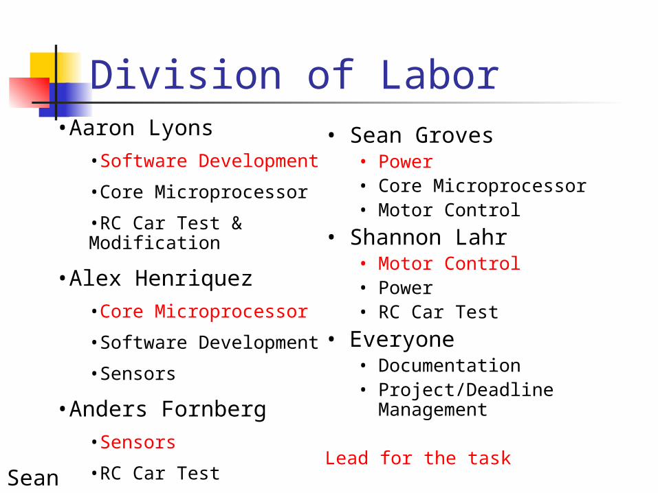
Division of Labor•Aaron Lyons
•Software Development
•Core Microprocessor
•RC Car Test & Modification
•Alex Henriquez•Core Microprocessor
•Software Development
•Sensors
•Anders Fornberg•Sensors
•RC Car Test
•Motor Control
• Sean Groves• Power• Core Microprocessor• Motor Control
• Shannon Lahr• Motor Control • Power• RC Car Test
• Everyone• Documentation• Project/Deadline
Management
Lead for the taskSean

Milestone 1
FPGA control of drive/steering and Chip Select
Sampling from Sensors Interrupt Controller Dip Switches RS232 Communication
Sean

Milestone 2
Boot Monitor LCD Implementation Mounting Specifications LED/Audio Integration Subsystem Integration Multiple Mode Operation
Sean

Future Concerns
Physical limitations that software can not cope with
Tracking Speed of Sensors Board integrity during testing Low Speed Response
Sean

Project SchedualeProject ScheduleProject Schedule
Sean

Parts List/Cost Estimate Main Board Description Price Quantity Total
-Processor MC68HC11 $0 1 $0
-EPROM Fairchild 27C512 $0 1 $0 -FPGA Spartan XCS10 $0 2 $0
-RAM Cypress 62258 $0 1 $0 -Board $25 1 $25 -Plastic Standoffs $0.20 10 $2 SensorsFront, Back, Side, Angle Devantech SRF04 Ranger $35 6 $210
Other Parts-RC Car Rustler by Traxxas $165 1 $165
-Battery Charger AC/DC Charger $40 1 $40
-Battery 7.2V Battery $15 2 $30
-Battery 9 V Battery $3 8 $24
-Plexi Glass $5 10 x 12 $5
-Metal $10 10 x 12 $10
-Metal Standoffs $1.70 20 $34.00 -Tether ~$.10/ft 40ft $4
Total $548.60
Sean

QUESTIONS???QUESTIONS???