2003 nissan altima 2.5 serivce manual av
DESCRIPTION
2003 Nissan Altima 2.5 Serivce ManualTRANSCRIPT
AV-1
AUDIO, VISUAL & TELEPHONE SYSTEM
K ELECTRICAL
CONTENTS
C
D
E
F
G
H
I
J
L
M
SECTION
A
B
AV
Revision: May 2004 2003 Altima
PRECAUTIONS .......................................................... 2Precautions for Supplemental Restraint System (SRS) “AIR BAG” and “SEAT BELT PRE-TEN-SIONER” .................................................................. 2Wiring Diagrams and Trouble Diagnosis .................. 2
PREPARATION ........................................................... 3Commercial Service Tool ......................................... 3
AUDIO ......................................................................... 4System Description .................................................. 4
BASE AND MIDLINE SYSTEM ............................. 4BOSE SYSTEM .................................................... 4SPEED DEPENDENT VOLUME CONTROL (MIDLINE SYSTEM AND BOSE SYSTEM) .......... 4
Circuit Diagram ........................................................ 5BASE SYSTEM ..................................................... 5MIDLINE SYSTEM ................................................ 6BOSE SYSTEM .................................................... 7
Wiring Diagram — AUDIO — ................................... 8BASE SYSTEM ..................................................... 8MIDLINE SYSTEM ...............................................11BOSE SYSTEM .................................................. 14
Wiring Diagram - REMOTE - .................................. 18Terminals and Reference Value for Audio Unit (Except Bose) ......................................................... 19Terminals and Reference Value for Audio Unit
(Bose) ..................................................................... 20Terminals and Reference Value for Bose Speaker Amp. ....................................................................... 21Steering Wheel Audio Control Switch Resistance Check ..................................................................... 22Removal and Installation ........................................ 22
AUDIO UNIT ........................................................ 22DOOR SPEAKER ................................................ 22TWEETER SPEAKER ......................................... 23REAR SPEAKER ................................................ 23SUBWOOFER SPEAKER ................................... 23BOSE SPEAKER AMP. ....................................... 23STEERING WHEEL AUDIO CONTROL SWITCHES ......................................................... 24
Trouble Diagnoses ................................................. 24AUDIO UNIT ........................................................ 24BASE AND MIDLINE SYSTEM ........................... 24BOSE SYSTEM ................................................... 24
AUDIO ANTENNA .................................................... 26System Description ................................................. 26Wiring Diagram -W/ANT- ........................................ 27Location of Antenna ................................................ 28Window Antenna Repair ......................................... 28
ELEMENT CHECK .............................................. 28ELEMENT REPAIR ............................................. 29

AV-2
PRECAUTIONS
Revision: May 2004 2003 Altima
PRECAUTIONS PFP:00001
Precautions for Supplemental Restraint System (SRS) “AIR BAG” and “SEAT BELT PRE-TENSIONER” EKS00675
The Supplemental Restraint System such as “AIR BAG” and “SEAT BELT PRE-TENSIONER”, used alongwith a front seat belt, helps to reduce the risk or severity of injury to the driver and front passenger for certaintypes of collision. This system includes seat belt switch inputs and dual stage front air bag modules. The SRSsystem uses the seat belt switches to determine the front air bag deployment, and may only deploy one frontair bag, depending on the severity of a collision and whether the front occupants are belted or unbelted.Information necessary to service the system safely is included in the SRS and SB section of this Service Man-ual.WARNING: To avoid rendering the SRS inoperative, which could increase the risk of personal injury or death
in the event of a collision which would result in air bag inflation, all maintenance must be per-formed by an authorized NISSAN/INFINITI dealer.
Improper maintenance, including incorrect removal and installation of the SRS, can lead to per-sonal injury caused by unintentional activation of the system. For removal of Spiral Cable and AirBag Module, see the SRS section.
Do not use electrical test equipment on any circuit related to the SRS unless instructed to in thisService Manual. SRS wiring harnesses can be identified by yellow and/or orange harnesses orharness connectors.
Wiring Diagrams and Trouble Diagnosis EKS003IU
When you read wiring diagrams, refer to the following: Refer to GI-12, "How to Read Wiring Diagrams" .
Refer to PG-3, "POWER SUPPLY ROUTING CIRCUIT" .When you perform trouble diagnosis, refer to the following: Refer to GI-10, "HOW TO FOLLOW TEST GROUPS IN TROUBLE DIAGNOSES" .
Refer to GI-25, "How to Perform Efficient Diagnosis for an Electrical Incident" .

PREPARATION
AV-3
C
D
E
F
G
H
I
J
L
M
A
B
AV
Revision: May 2004 2003 Altima
PREPARATION PFP:00002
Commercial Service Tool EKS003K4
Tool name Description
Power tool
Loosening bolts and nuts
PBIC0191E
AV-4
AUDIO
Revision: May 2004 2003 Altima
AUDIO PFP:28111
System Description EKS003IW
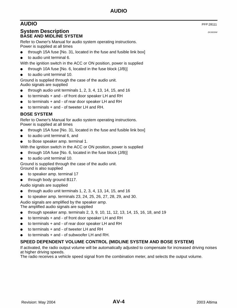
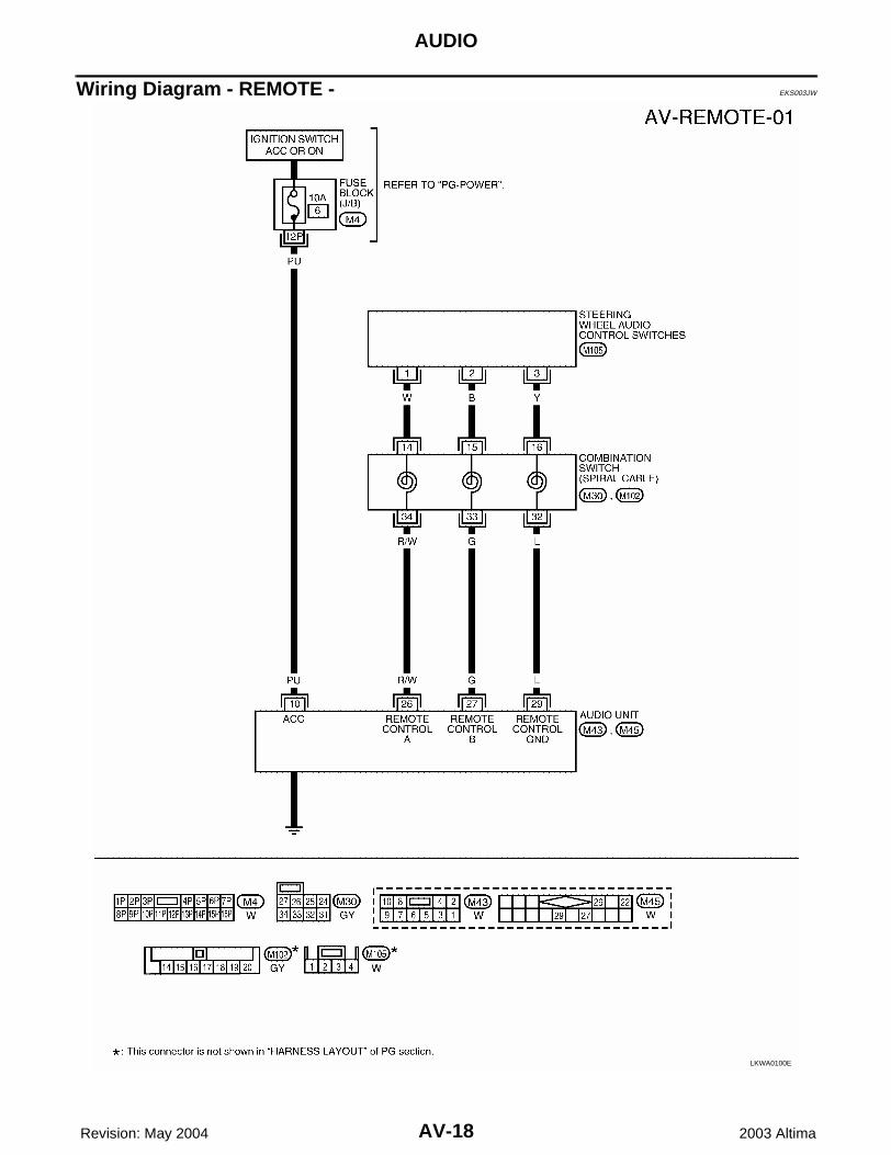
BASE AND MIDLINE SYSTEMRefer to Owner's Manual for audio system operating instructions.Power is supplied at all times through 15A fuse [No. 31, located in the fuse and fusible link box] to audio unit terminal 6.With the ignition switch in the ACC or ON position, power is supplied through 10A fuse [No. 6, located in the fuse block (J/B)] to audio unit terminal 10.Ground is supplied through the case of the audio unit.Audio signals are supplied through audio unit terminals 1, 2, 3, 4, 13, 14, 15, and 16 to terminals + and - of front door speaker LH and RH to terminals + and - of rear door speaker LH and RH to terminals + and - of tweeter LH and RH.
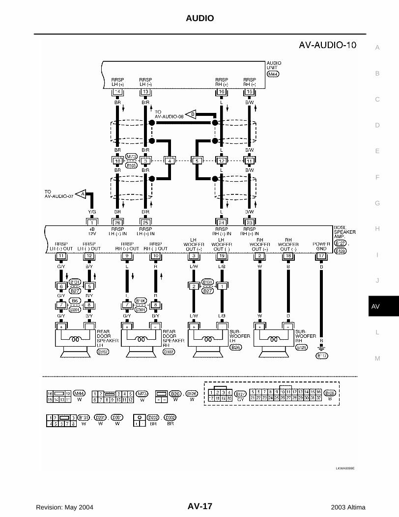
BOSE SYSTEMRefer to Owner's Manual for audio system operating instructions.Power is supplied at all times through 15A fuse [No. 31, located in the fuse and fusible link box] to audio unit terminal 6, and to Bose speaker amp. terminal 1.With the ignition switch in the ACC or ON position, power is supplied through 10A fuse [No. 6, located in the fuse block (J/B)] to audio unit terminal 10.Ground is supplied through the case of the audio unit.Ground is also supplied to speaker amp. terminal 17 through body ground B117.Audio signals are supplied through audio unit terminals 1, 2, 3, 4, 13, 14, 15, and 16 to speaker amp. terminals 23, 24, 25, 26, 27, 28, 29, and 30.Audio signals are amplified by the speaker amp.The amplified audio signals are supplied through speaker amp. terminals 2, 3, 9, 10, 11, 12, 13, 14, 15, 16, 18, and 19 to terminals + and - of front door speaker LH and RH to terminals + and - of rear door speaker LH and RH to terminals + and - of tweeter LH and RH to terminals + and - of subwoofer LH and RH.
SPEED DEPENDENT VOLUME CONTROL (MIDLINE SYSTEM AND BOSE SYSTEM)If activated, the radio output volume will be automatically adjusted to compensate for increased driving noisesat higher driving speeds.The radio receives a vehicle speed signal from the combination meter, and selects the output volume.
AUDIO
AV-5
C
D
E
F
G
H
I
J
L
M
A
B
AV
Revision: May 2004 2003 Altima
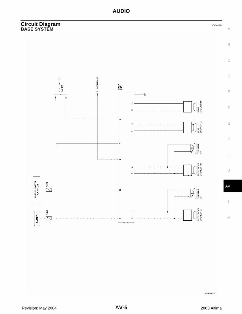
Circuit Diagram EKS003JU
BASE SYSTEM
LKWA0001E

AV-6
AUDIO
Revision: May 2004 2003 Altima
MIDLINE SYSTEM
LKWA0002E

AUDIO
AV-7
C
D
E
F
G
H
I
J
L
M
A
B
AV
Revision: May 2004 2003 Altima
BOSE SYSTEM
LKWA0003E
AV-8
AUDIO
Revision: May 2004 2003 Altima
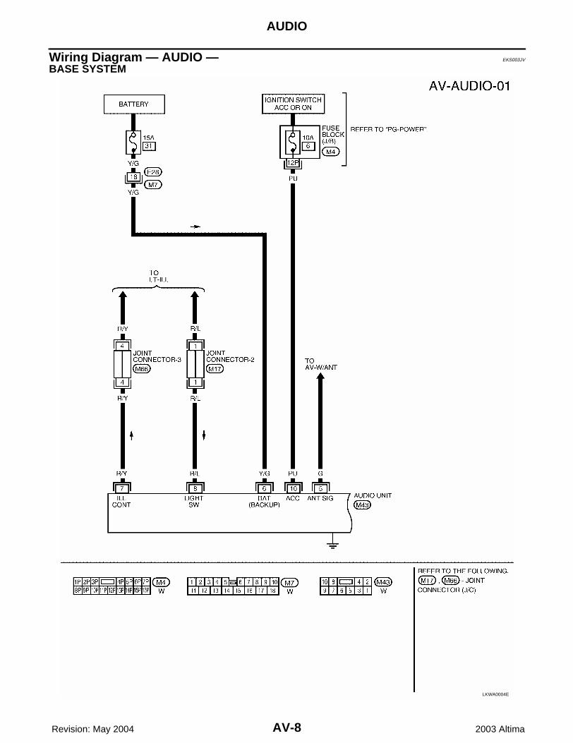
Wiring Diagram — AUDIO — EKS003JV
BASE SYSTEM
LKWA0004E

AUDIO
AV-9
C
D
E
F
G
H
I
J
L
M
A
B
AV
Revision: May 2004 2003 Altima
LKWA0093E

AV-10
AUDIO
Revision: May 2004 2003 Altima
LKWA0094E

AUDIO
AV-11
C
D
E
F
G
H
I
J
L
M
A
B
AV
Revision: May 2004 2003 Altima
MIDLINE SYSTEM
LKWA0007E

AV-12
AUDIO
Revision: May 2004 2003 Altima
LKWA0095E

AUDIO
AV-13
C
D
E
F
G
H
I
J
L
M
A
B
AV
Revision: May 2004 2003 Altima
LKWA0096E

AV-14
AUDIO
Revision: May 2004 2003 Altima
BOSE SYSTEM
WKWA0497E

AUDIO
AV-15
C
D
E
F
G
H
I
J
L
M
A
B
AV
Revision: May 2004 2003 Altima
WKWA0498E

AV-16
AUDIO
Revision: May 2004 2003 Altima
LKWA0098E
AUDIO
AV-17
C
D
E
F
G
H
I
J
L
M
A
B
AV
Revision: May 2004 2003 Altima
LKWA0099E
AV-18
AUDIO
Revision: May 2004 2003 Altima
Wiring Diagram - REMOTE - EKS003JW
LKWA0100E
AUDIO
AV-19
C
D
E
F
G
H
I
J
L
M
A
B
AV
Revision: May 2004 2003 Altima
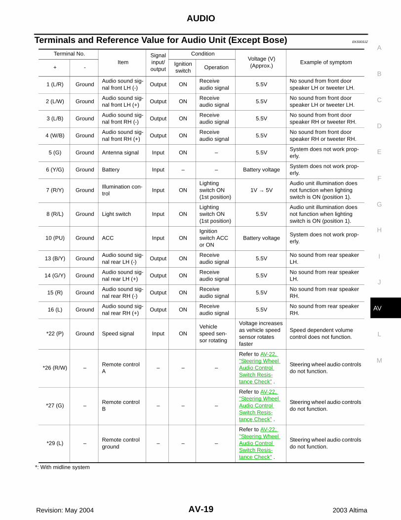
Terminals and Reference Value for Audio Unit (Except Bose) EKS003JZ
*: With midline system
Terminal No.
ItemSignal input/output
ConditionVoltage (V)(Approx.)
Example of symptom+ -
Ignition switch
Operation
1 (L/R) GroundAudio sound sig-nal front LH (-)
Output ONReceive audio signal
5.5VNo sound from front door speaker LH or tweeter LH.
2 (L/W) GroundAudio sound sig-nal front LH (+)
Output ONReceive audio signal
5.5VNo sound from front door speaker LH or tweeter LH.
3 (L/B) GroundAudio sound sig-nal front RH (-)
Output ONReceive audio signal
5.5VNo sound from front door speaker RH or tweeter RH.
4 (W/B) GroundAudio sound sig-nal front RH (+)
Output ONReceive audio signal
5.5VNo sound from front door speaker RH or tweeter RH.
5 (G) Ground Antenna signal Input ON – 5.5VSystem does not work prop-erly.
6 (Y/G) Ground Battery Input – – Battery voltageSystem does not work prop-erly.
7 (R/Y) GroundIllumination con-trol
Input ONLighting switch ON (1st position)
1V → 5VAudio unit illumination does not function when lighting switch is ON (position 1).
8 (R/L) Ground Light switch Input ONLighting switch ON (1st position)
5.5VAudio unit illumination does not function when lighting switch is ON (position 1).
10 (PU) Ground ACC Input ONIgnition switch ACC or ON
Battery voltageSystem does not work prop-erly.
13 (B/Y) GroundAudio sound sig-nal rear LH (-)
Output ONReceive audio signal
5.5VNo sound from rear speaker LH.
14 (G/Y) GroundAudio sound sig-nal rear LH (+)
Output ONReceive audio signal
5.5VNo sound from rear speaker LH.
15 (R) GroundAudio sound sig-nal rear RH (-)
Output ONReceive audio signal
5.5VNo sound from rear speaker RH.
16 (L) GroundAudio sound sig-nal rear RH (+)
Output ONReceive audio signal
5.5VNo sound from rear speaker RH.
*22 (P) Ground Speed signal Input ONVehicle speed sen-sor rotating
Voltage increases as vehicle speed sensor rotates faster
Speed dependent volume control does not function.
*26 (R/W) –Remote control A
– – –
Refer to AV-22, "Steering Wheel Audio Control Switch Resis-tance Check" .
Steering wheel audio controls do not function.
*27 (G) –Remote control B
– – –
Refer to AV-22, "Steering Wheel Audio Control Switch Resis-tance Check" .
Steering wheel audio controls do not function.
*29 (L) –Remote control ground
– – –
Refer to AV-22, "Steering Wheel Audio Control Switch Resis-tance Check" .
Steering wheel audio controls do not function.
AV-20
AUDIO
Revision: May 2004 2003 Altima
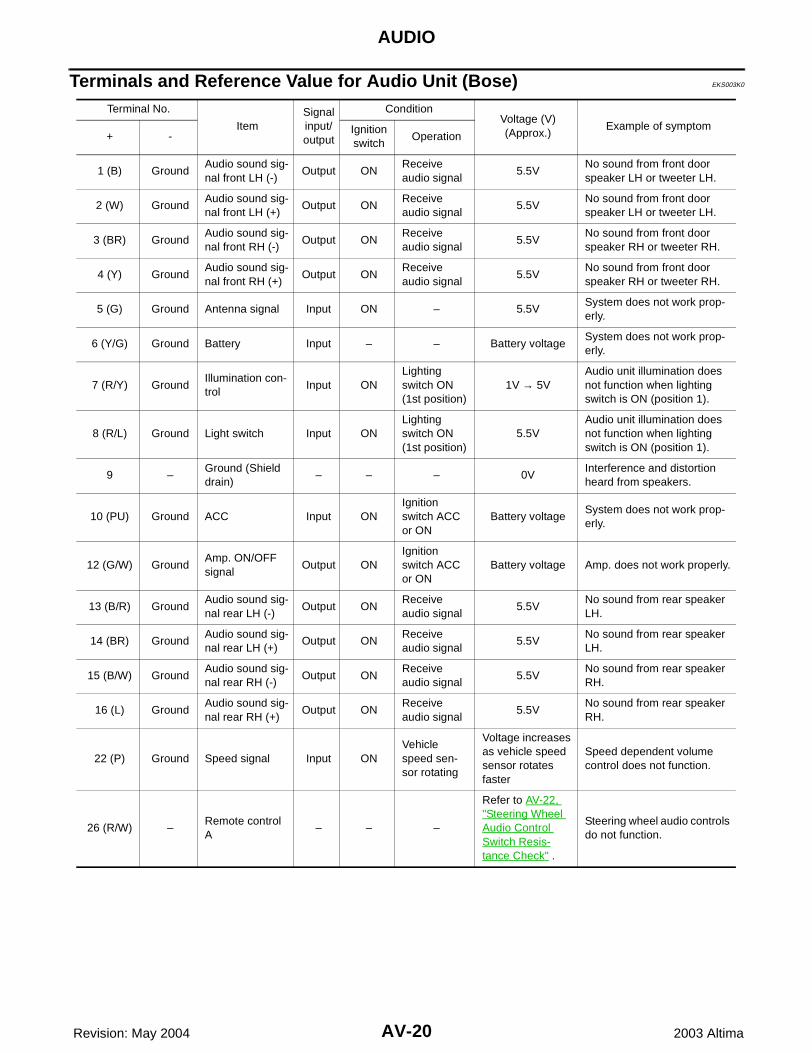
Terminals and Reference Value for Audio Unit (Bose) EKS003K0
Terminal No.
ItemSignal input/output
ConditionVoltage (V)(Approx.)
Example of symptom+ -
Ignition switch
Operation
1 (B) GroundAudio sound sig-nal front LH (-)
Output ONReceive audio signal
5.5VNo sound from front door speaker LH or tweeter LH.
2 (W) GroundAudio sound sig-nal front LH (+)
Output ONReceive audio signal
5.5VNo sound from front door speaker LH or tweeter LH.
3 (BR) GroundAudio sound sig-nal front RH (-)
Output ONReceive audio signal
5.5VNo sound from front door speaker RH or tweeter RH.
4 (Y) GroundAudio sound sig-nal front RH (+)
Output ONReceive audio signal
5.5VNo sound from front door speaker RH or tweeter RH.
5 (G) Ground Antenna signal Input ON – 5.5VSystem does not work prop-erly.
6 (Y/G) Ground Battery Input – – Battery voltageSystem does not work prop-erly.
7 (R/Y) GroundIllumination con-trol
Input ONLighting switch ON (1st position)
1V → 5VAudio unit illumination does not function when lighting switch is ON (position 1).
8 (R/L) Ground Light switch Input ONLighting switch ON (1st position)
5.5VAudio unit illumination does not function when lighting switch is ON (position 1).
9 –Ground (Shield drain)
– – – 0VInterference and distortion heard from speakers.
10 (PU) Ground ACC Input ONIgnition switch ACC or ON
Battery voltageSystem does not work prop-erly.
12 (G/W) GroundAmp. ON/OFF signal
Output ONIgnition switch ACC or ON
Battery voltage Amp. does not work properly.
13 (B/R) GroundAudio sound sig-nal rear LH (-)
Output ONReceive audio signal
5.5VNo sound from rear speaker LH.
14 (BR) GroundAudio sound sig-nal rear LH (+)
Output ONReceive audio signal
5.5VNo sound from rear speaker LH.
15 (B/W) GroundAudio sound sig-nal rear RH (-)
Output ONReceive audio signal
5.5VNo sound from rear speaker RH.
16 (L) GroundAudio sound sig-nal rear RH (+)
Output ONReceive audio signal
5.5VNo sound from rear speaker RH.
22 (P) Ground Speed signal Input ONVehicle speed sen-sor rotating
Voltage increases as vehicle speed sensor rotates faster
Speed dependent volume control does not function.
26 (R/W) –Remote control A
– – –
Refer to AV-22, "Steering Wheel Audio Control Switch Resis-tance Check" .
Steering wheel audio controls do not function.

AUDIO
AV-21
C
D
E
F
G
H
I
J
L
M
A
B
AV
Revision: May 2004 2003 Altima
Terminals and Reference Value for Bose Speaker Amp. EKS003K1
27 (G) –Remote control B
– – –
Refer to AV-22, "Steering Wheel Audio Control Switch Resis-tance Check" .
Steering wheel audio controls do not function.
29 (L) –Remote control ground
– – –
Refer to AV-22, "Steering Wheel Audio Control Switch Resis-tance Check" .
Steering wheel audio controls do not function.
Terminal No.
ItemSignal input/output
ConditionVoltage (V)(Approx.)
Example of symptom+ -
Ignition switch
Operation
Terminal No.
ItemSignal input/output
ConditionVoltage (V)(Approx.)
Example of symptom+ -
Ignition switch
Operation
1 (Y/G) Ground Battery Input – – Battery voltageSystem does not work prop-erly.
2 (W) GroundSubwoofer RH (+)
Output ONReceive audio signal
5 - 7.5VNo sound from subwoofer RH.
3 (L/W) GroundSubwoofer LH (+)
Output ONReceive audio signal
5 - 7.5VNo sound from subwoofer LH.
9 (L) GroundRear door speaker RH (+)
Output ONReceive audio signal
5 - 7.5VNo sound from rear door speaker RH.
10 (R) GroundRear door speaker RH (-)
Output ONReceive audio signal
5 - 7.5VNo sound from rear door speaker RH.
11 (G/Y) GroundRear door speaker LH (+)
Output ONReceive audio signal
5 - 7.5VNo sound from rear door speaker LH.
12 (B/Y) GroundRear door speaker LH (-)
Output ONReceive audio signal
5 - 7.5VNo sound from rear door speaker LH.
13 (W/B) GroundFront door speaker RH and tweeter RH (+)
Output ONReceive audio signal
5 - 7.5VNo sound from front door speaker RH or tweeter RH.
14 (L/B) GroundFront door speaker RH and tweeter RH (-)
Output ONReceive audio signal
5 - 7.5VNo sound from front door speaker RH or tweeter RH.
15 (L/W) GroundFront door speaker LH and tweeter LH (+)
Output ONReceive audio signal
5 - 7.5VNo sound from front door speaker LH or tweeter LH.
16 (L/R) GroundFront door speaker LH and tweeter LH (-)
Output ONReceive audio signal
5 - 7.5VNo sound from front door speaker LH or tweeter LH.
17 (B) Ground Ground – – – – –
18 (B) GroundSubwoofer RH (-)
Output ONReceive audio signal
5 - 7.5VNo sound from subwoofer RH.
19 (L/B) Ground Subwoofer LH (-) Output ONReceive audio signal
5 - 7.5VNo sound from subwoofer LH.
23 (B/W) GroundRear speaker RH (-)
Input ONReceive audio signal
5 - 7.5VNo sound from RH rear speakers.
24 (L) GroundRear speaker RH (+)
Input ONReceive audio signal
5 - 7.5VNo sound from RH rear speakers.
25 (B/R) GroundRear speaker LH (-)
Input ONReceive audio signal
5 - 7.5VNo sound from LH rear speakers.

AV-22
AUDIO
Revision: May 2004 2003 Altima
Steering Wheel Audio Control Switch Resistance Check EKS003K2
*: Audio unit terminals.
Removal and Installation EKS003K3
AUDIO UNIT1. Remove cluster lid C. Refer to IP-12, "Cluster Lid C" .2. Remove cluster lid D. Refer to IP-12, "Cluster Lid D" .3. Remove audio unit screws using power tool and slide audio unit
forward.4. Disconnect connectors and antenna cable and then remove
audio unit.Install in the reverse order of removal.
DOOR SPEAKER1. Remove door finisher. Refer to EI-27, "Removal and Installation" .
26 (BR) GroundRear speaker LH (+)
Input ONReceive audio signal
5 - 7.5VNo sound from LH rear speakers.
27 (BR) GroundFront speaker RH (-)
Input ONReceive audio signal
5 - 7.5VNo sound from RH front speakers.
28 (Y) GroundFront speaker RH (+)
Input ONReceive audio signal
5 - 7.5VNo sound from RH front speakers.
29 (B) GroundFront speaker LH (-)
Input ONReceive audio signal
5 - 7.5VNo sound from LH front speakers.
30 (W) GroundFront speaker LH (+)
Input ONReceive audio signal
5 - 7.5VNo sound from LH front speakers.
31 (G/W) GroundAmp. ON/OFF signal
Input ON – 10VSystem does not work prop-erly.
Terminal No.
ItemSignal input/output
ConditionVoltage (V)(Approx.)
Example of symptom+ -
Ignition switch
Operation
*Terminal No.(wire color) Signal name Condition
Resistance (Ω)(Approx.)
+ -
27 (G) 29 (L) Volume (down) Depress volume down switch 652Ω
26 (R/W) 29 (L) Volume (up) Depress volume up switch 652Ω
27 (G) 29 (L) Mode Depress (station) down switch 165Ω
26 (R/W) 29 (L) Up (next) Depress (station) up switch 165Ω
26 (R/W) 29 (L) Down (previous) Depress mode switch 1Ω
LKIA0056E
AUDIO
AV-23
C
D
E
F
G
H
I
J
L
M
A
B
AV
Revision: May 2004 2003 Altima
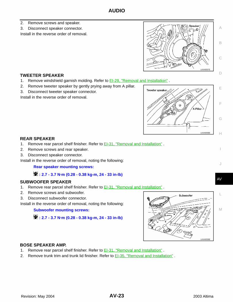
2. Remove screws and speaker.3. Disconnect speaker connector.Install in the reverse order of removal.
TWEETER SPEAKER1. Remove windshield garnish molding. Refer to EI-29, "Removal and Installation" .2. Remove tweeter speaker by gently prying away from A pillar.3. Disconnect tweeter speaker connector.Install in the reverse order of removal.
REAR SPEAKER1. Remove rear parcel shelf finisher. Refer to EI-31, "Removal and Installation" .2. Remove screws and rear speaker.3. Disconnect speaker connector.Install in the reverse order of removal, noting the following:
SUBWOOFER SPEAKER1. Remove rear parcel shelf finisher. Refer to EI-31, "Removal and Installation" .2. Remove screws and subwoofer.3. Disconnect subwoofer connector.Install in the reverse order of removal, noting the following:
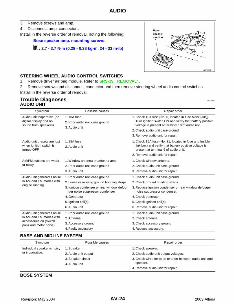
BOSE SPEAKER AMP.1. Remove rear parcel shelf finisher. Refer to EI-31, "Removal and Installation" .2. Remove trunk trim and trunk lid finisher. Refer to EI-35, "Removal and Installation" .
LKIA0057E
LKIA0058E
Rear speaker mounting screws:
: 2.7 - 3.7 N·m (0.28 - 0.38 kg-m, 24 - 33 in-lb)
Subwoofer mounting screws:
: 2.7 - 3.7 N·m (0.28 - 0.38 kg-m, 24 - 33 in-lb)
LKIA0059E
AV-24
AUDIO
Revision: May 2004 2003 Altima
3. Remove screws and amp.4. Disconnect amp. connectors.Install in the reverse order of removal, noting the following:
STEERING WHEEL AUDIO CONTROL SWITCHES1. Remove driver air bag module. Refer to SRS-39, "REMOVAL" .2. Remove screws and disconnect connector and then remove steering wheel audio control switches. Install in the reverse order of removal.
Trouble Diagnoses EKS003IZ
AUDIO UNIT
BASE AND MIDLINE SYSTEM
BOSE SYSTEM
Bose speaker amp. mounting screws:
: 2.7 - 3.7 N·m (0.28 - 0.38 kg-m, 24 - 33 in-lb)
LKIA0062E
Symptom Possible causes Repair order
Audio unit inoperative (no digital display and no sound from speakers).
1. 10A fuse
2. Poor audio unit case ground
3. Audio unit
1. Check 10A fuse [No. 6, located in fuse block (J/B)]. Turn ignition switch ON and verify that battery positive voltage is present at terminal 10 of audio unit.
2. Check audio unit case ground.
3. Remove audio unit for repair.
Audio unit presets are lost when ignition switch is turned OFF.
1. 15A fuse
2. Audio unit
1. Check 15A fuse (No. 31, located in fuse and fusible link box) and verify that battery positive voltage is present at terminal 6 of audio unit.
2. Remove audio unit for repair.
AM/FM stations are weak or noisy.
1. Window antenna or antenna amp.
2. Poor audio unit case ground
3. Audio unit
1. Check window antenna.
2. Check audio unit case ground.
3. Remove audio unit for repair.
Audio unit generates noise in AM and FM modes with engine running.
1. Poor audio unit case ground
2. Loose or missing ground bonding straps
3. Ignition condenser or rear window defog-ger noise suppressor condenser
4. Generator
5. Ignition coil(s)
6. Audio unit
1. Check audio unit case ground.
2. Check ground bonding straps.
3. Replace ignition condenser or rear window defogger noise suppressor condenser.
4. Check generator.
5. Check ignition coil(s).
6. Remove audio unit for repair.
Audio unit generates noise in AM and FM modes with accessories on (switch pops and motor noise).
1. Poor audio unit case ground
2. Antenna
3. Accessory ground
4. Faulty accessory
1. Check audio unit case ground.
2. Check antenna.
3. Check accessory ground.
4. Replace accessory.
Symptom Possible causes Repair order
Individual speaker is noisy or inoperative.
1. Speaker
2. Audio unit output
3. Speaker circuit
4. Audio unit
1. Check speaker.
2. Check audio unit output voltages.
3. Check wires for open or short between audio unit and speaker.
4. Remove audio unit for repair.

AUDIO
AV-25
C
D
E
F
G
H
I
J
L
M
A
B
AV
Revision: May 2004 2003 Altima
Symptom Possible causes Repair order
Audio unit controls are operational, but no sound is heard from any speaker.
1. 15A fuse
2. Amp. ON/OFF signal circuit
3. Speaker amp. ground
1. Check 15A fuse [No. 31, located in the fuse block (J/B)]. Verify battery positive voltage is present at terminal 1 of the speaker amp.
2. Check harness continuity between audio unit terminal 12 and speaker amp. terminal 31.
3. Check harness continuity between speaker amp. ter-minal 17 and ground.
Individual speaker is noisy or inoperative.
1. Speaker
2. Output circuits to speaker
3. Speaker amp. power supply and ground
1. Check speaker.
2. Check the output circuits to speaker:
– between audio unit and speaker amp.
– between speaker amp. and speaker
3. Check speaker amp. power supply and ground condi-tion.

AV-26
AUDIO ANTENNA
Revision: May 2004 2003 Altima
AUDIO ANTENNA PFP:28200
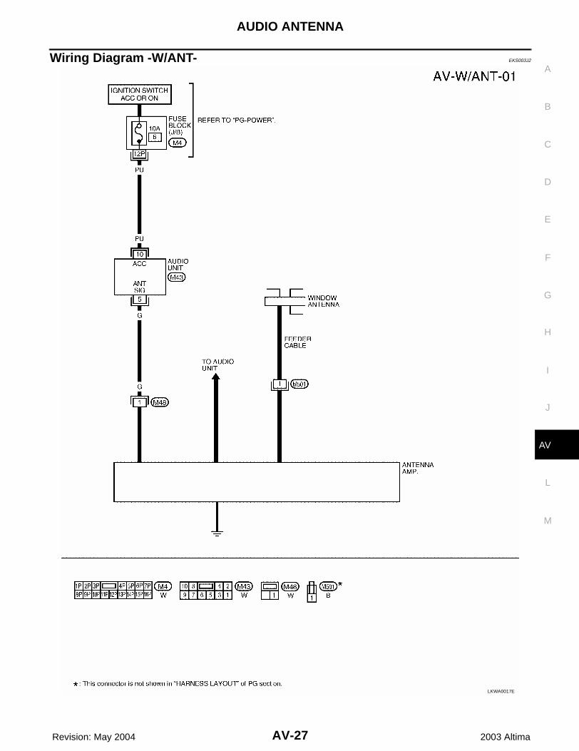
System Description EKS003J1
With the ignition switch in ACC or ON, power is supplied through 10A fuse [No. 6, located in the fuse block (J/B)] to audio unit terminal 10.Ground is supplied through the case of the antenna amp.When the radio switch is turned ON, antenna signal is supplied through audio unit terminal 5 to the antenna amp. terminal 1.Then the antenna amp. is activated.The amplified radio signals are supplied to the audio unit through the antenna amp.
AUDIO ANTENNA
AV-27
C
D
E
F
G
H
I
J
L
M
A
B
AV
Revision: May 2004 2003 Altima
Wiring Diagram -W/ANT- EKS003J2
LKWA0017E

AV-28
AUDIO ANTENNA
Revision: May 2004 2003 Altima
Location of Antenna EKS003J3
Window Antenna Repair EKS003J4
ELEMENT CHECK1. Attach probe circuit tester (ohm setting) to antenna terminal on
each side.
When measuring continuity, wrap tin foil around the top ofprobe. Then, press the foil against the wire with your finger.
LKIA0012E
SEL250I
SEL122R

AUDIO ANTENNA
AV-29
C
D
E
F
G
H
I
J
L
M
A
B
AV
Revision: May 2004 2003 Altima
2. If an element is broken, no continuity will exist.
3. To locate a break, move probe along element. Tester needle willswing abruptly when probe passes the broken point.
ELEMENT REPAIRRefer to GW-58, "Filament Repair" .
SEL252I
SEL253I

AV-30
AUDIO ANTENNA
Revision: May 2004 2003 Altima