2001 copyright scut dt&p labs 1 prime of mpls ( as an ip over atm solution)
TRANSCRIPT

2001 Copyright 2001 Copyright SCUT DT&P LabsSCUT DT&P Labs 1
Prime of MPLSPrime of MPLS
( As An IP over ATM ( As An IP over ATM Solution)Solution)
2001 Copyright 2001 Copyright SCUT DT&P LabsSCUT DT&P Labs 2
1.1. Multi protocol Label Switching (MPLS)Multi protocol Label Switching (MPLS)
MPLS is an emerging Internet Engineering Task Force (IETF) IP forwarding standard in 1997.
ITU-T accepts the Label Distribution Protocol (LDP) of MPLS as the signalling standard of transmission in public data network in 1999.
It is termed ‘MultiprotocolMultiprotocol’ as its principles can be applied to several data link layer protocols in combination with several network layer protocols.
The subject of this chapter is the specific implementation of MPLS as an IP over ATM technologyIP over ATM technology..
2001 Copyright 2001 Copyright SCUT DT&P LabsSCUT DT&P Labs 3
2. Principles of MPLS2. Principles of MPLS
When a packet arrives at the incoming node of an MPLS network, the packet is analysed and put into a forward forward equivalence classequivalence class (FEC).
A forward equivalence classforward equivalence class is defined as all layer three layer three packetspackets that can be treated identically by the network.
Each FEC is associated with a route through the network.
Each node within an MPLS network runs routing protocols, or has static routes defined, and thus knows the best path through the network.

2001 Copyright 2001 Copyright SCUT DT&P LabsSCUT DT&P Labs 4
2. Principles of MPLS (Contd.)2. Principles of MPLS (Contd.)
Arriving at the MPLS network, the packet has a label attached. This label specifies the portion between the incoming node and the next node on the packet’s intended route.
When the packet arrives at the next node, the label attached to it is read and used as a reference into a label database. A new label is obtained from this database.
This new label corresponds to the next section of the packet’s intended route.
2001 Copyright 2001 Copyright SCUT DT&P LabsSCUT DT&P Labs 5
2. Principles of MPLS (Contd.)2. Principles of MPLS (Contd.)
The new label is switched with the old label and the packet is forwarded with the new label attached.
This process is repeated throughout the network until the packet arrives at the far edge of the MPLS network.
When the packet reaches the outgoing node of the MPLS network, the final label is stripped off and the packet returns to whichever method of forwarding is used outside the MPLS network.
2001 Copyright 2001 Copyright SCUT DT&P LabsSCUT DT&P Labs 6
3. MPLS Implementations3. MPLS Implementations
MPLS as a layer three or IP solutionlayer three or IP solution. In this case, the label is an additional piece of data appended to the beginning of the IP packet.
MPLS components know how to switch using the label, rather than routing on the contents of the IP header.
MPLS as an IP over Frame Relay solutionIP over Frame Relay solution. In this case, the label is the data link control identifier (DLCI) in the Frame Relay header.
MPLS as an IP over ATM solutionIP over ATM solution. In this case, the label is the ATM VPI/VCI value within the ATM cell header.

2001 Copyright 2001 Copyright SCUT DT&P LabsSCUT DT&P Labs 7
4. MPLS: 4. MPLS: IP over ATM solutionIP over ATM solution
Broadly speaking, we can define an ATM network as a network of ATM hardware, in which this hardware is controlled by ATM software.
In contrast, an MPLS network (as an IP over ATM solution) is a network of ATM hardware in which this hardware is controlled by MPLS software.
In implementing MPLS as an IP over ATM technology, the MPLS ‘label’ is the ATM VPI/VCI value contained within the ATM cell header.

2001 Copyright 2001 Copyright SCUT DT&P LabsSCUT DT&P Labs 8
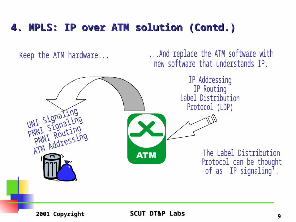
4. MPLS: 4. MPLS: IP over ATM solution IP over ATM solution (Contd.)(Contd.)
The significant difference between MPLS and otherother IP over ATM solutions, is that the MPLS connections are set up by the Label Distribution ProtocolLabel Distribution Protocol (LDP), and not by traditional ATM signalling protocols.
The MPLS LDP understands and usesuses IP addresses, thus providing seamless integration with existing IP networks while harnessing the high-speed switching of ATM.
In addition to using IP addressing, the routing protocolsrouting protocols used in MPLS networks are the samesame as those used in IP networks.
2001 Copyright 2001 Copyright SCUT DT&P LabsSCUT DT&P Labs 9
4. MPLS: 4. MPLS: IP over ATM solution IP over ATM solution (Contd.)(Contd.)

2001 Copyright 2001 Copyright SCUT DT&P LabsSCUT DT&P Labs 10
5. 5. MPLS Network Architecture
MPLS network architecture employs two main types of routers, label edge routerslabel edge routers and label switching routerslabel switching routers.
Label edge routers (LERLERs) are located at the edge of the network to perform traditional routing functions and to provide connectivity to user networks.
The LERs analyse and classify the incoming IP packet, adding a short label which indicates which LSP the packet should take.
In practice, the LERs are IP routers with an ATM interface running MPLS software (LDP).

2001 Copyright 2001 Copyright SCUT DT&P LabsSCUT DT&P Labs 11
5. 5. MPLS Network Architecture (Contd.)
Label switching routers (LSRLSRs) located in the centre of the network to perform high-performance label switching routing. The LSRs forward packets, identified by the label, along the LSP.
In practice, the LSRs are ATM switches running MPLS software (LDP).

2001 Copyright 2001 Copyright SCUT DT&P LabsSCUT DT&P Labs 12
5. 5. MPLS Network Architecture (Contd.)

2001 Copyright 2001 Copyright SCUT DT&P LabsSCUT DT&P Labs 13
6. 6. Label Distribution Protocol (LDP)
A label distribution protocollabel distribution protocol is a set of procedures by which MPLS nodes inform each other of the meaning of labels used to forward traffic between and through the nodes.
LDP is a new protocol defined for distributing labels.
It is the set of procedures and messages by which LSRs establish label switching pathslabel switching paths (LSPLSPs) through a network by mapping network layer routing information directly to data link layer switched paths.

2001 Copyright 2001 Copyright SCUT DT&P LabsSCUT DT&P Labs 14
6. 6. Label Distribution Protocol (LDP) (Contd.)
LDP associates a forwarding equivalence classforwarding equivalence class (FEC) with each LSP it creates.
The FEC associated with an LSP specifies which packets are mapped to that LSP.
Routing in an MPLS network is performed in the same way as in a legacy IP network.
Both LDP and routing information travel through the network on a default channel reserved for that purpose.
The channel 0,32channel 0,32 is used for this traffic.
2001 Copyright 2001 Copyright SCUT DT&P LabsSCUT DT&P Labs 15
7. Forward Equivalence Class (FEC)7. Forward Equivalence Class (FEC)
An FEC is defined as a group of layer three (network layer) packets that can be forwarded in the same manner.
An FEC may comprise traffic to a particular destination or it may be more specific, comprising traffic to a particular destination and distinct service requirements.
FECs are mapped directly to LSPs.
MPLS allows the IP packet to forwarding equivalence class mapping to be performed only once, that is, at the ingress to an MPLS network.
This facilitates complex mappings from IP packets to FEC that would otherwise be impractical.
2001 Copyright 2001 Copyright SCUT DT&P LabsSCUT DT&P Labs 16
7. Forward Equivalence Class (FEC) (Contd.)7. Forward Equivalence Class (FEC) (Contd.)
With FEC, the way to offer provisioned QoS is to map the packet at the ingress point to the preferred QoS level, and then to label the packet in some way.
MPLS offers an efficient method of labelling the QoS class associated with any particular packet.
MPLS does NOTNOT require that packet filtering in each LSR based on source and destination address, incoming interface, and other characteristics.
2001 Copyright 2001 Copyright SCUT DT&P LabsSCUT DT&P Labs 17
8. MPLS Advantages8. MPLS Advantages
Simplified ForwardingSimplified Forwarding Label swapping allows packet forwarding to be
considerably simplified. This means that it is easier to build a high-speed router using MPLS technology.
Efficient Explicit RoutingEfficient Explicit Routing Explicit routing, which is also called source routing. It is
carried only at the time that the label switched path is set up, and not with each packet.

2001 Copyright 2001 Copyright SCUT DT&P LabsSCUT DT&P Labs 18
8. MPLS Advantages (Contd.)8. MPLS Advantages (Contd.)
Service DifferentiationService Differentiation Since a packet is assigned to an FEC when it enters the
network, in determining the assignment the ingress router may use, any information it has about the packet, even if that information cannot be gleaned from the network layer header.
For example, packets arriving on different physical router ports may be assigned to different FECs.
A packet that enters the network at a particular router can be labeled differently than the same packet entering the network at a different router.
In contrast, conventional forwarding can only consider information which travels with the packet in the packet header.

2001 Copyright 2001 Copyright SCUT DT&P LabsSCUT DT&P Labs 19
8. MPLS Advantages (Contd.)8. MPLS Advantages (Contd.)
Multiple ServicesMultiple Services MPLS control components can coexist with traditional
ATM control components, thus supporting all existing ATM applications.
Signaling channel: ATMATM: VPI=0 / VCI=5 MPLSMPLS: VPI=0 / VCI=32
2001 Copyright 2001 Copyright SCUT DT&P LabsSCUT DT&P Labs 20
9. MPLS Scalability9. MPLS Scalability
Other available methods for interconnecting routers in an IP over ATM environment make use of one of the following:
A full mesh 'n- squared' overlay of virtual circuits between n ATM-attached routers;
A partial mesh of VCs between routers A partial mesh of VCs, plus the use of NHRP (Next Hop
Resolution Protocol) to facilitate on demand cut through SVCs.
PVC method requires all edge nodes to peer with all other edge nodes.

2001 Copyright 2001 Copyright SCUT DT&P LabsSCUT DT&P Labs 21
9. MPLS Scalability (Contd.)9. MPLS Scalability (Contd.)
MPLS improves the scalability of routing due to the reduced number of peers and the elimination of the 'n-squared' logical links between routers used to operate the routing protocols.
Because all LSRs run standard routing protocols, the number of the peers that routers need to communicate with is reduced to the number of the LSRs and LERs a given LSR is directly connected to.
2001 Copyright 2001 Copyright SCUT DT&P LabsSCUT DT&P Labs 22
10. MPLS and Layer 3 Forwarding10. MPLS and Layer 3 Forwarding
MPLS will not, and is not intended to, replace Layer 3 (L3) forwarding. L3 forwarding will be needed for a variety of reasons, including:
For scaling. Not every destination can be identified by a label. In most cases the label enables the traffic to get close to the destination, but not to reach the destination.
For security, to allow packet filtering at firewalls.
For forwarding at the initial router when hosts don't support MPLS.
For routing at the intra-domain routing protocols border.

2001 Copyright 2001 Copyright SCUT DT&P LabsSCUT DT&P Labs 23
11. Methods of Label Assignment11. Methods of Label Assignment
There are two methods of label assignment:
Scheme 1: Topology DrivenScheme 1: Topology Driven
Scheme 2: Traffic DrivenScheme 2: Traffic Driven

2001 Copyright 2001 Copyright SCUT DT&P LabsSCUT DT&P Labs 24
11. Methods of Label Assignment11. Methods of Label Assignment Topology DrivenTopology Driven In this scheme, labels are assigned to normal processing of
routing protocol traffic.
Labels are in general pre-assigned. If a route exists, a label has been assigned to it (and distributed).
Traffic may be label-swapped immediately it arrives. There is no label set-up latency at forwarding time.
This scheme requires LSRs to be able to process control traffic load only.
Labels can cover highly aggregated routes.
Amount of control information is proportional to the number of destinations.

2001 Copyright 2001 Copyright SCUT DT&P LabsSCUT DT&P Labs 25
11. Methods of Label Assignment11. Methods of Label Assignment Traffic DrivenTraffic Driven In this scheme, the arrival of data at an LSR triggers the
set-up of an LSP. Labels assignment and distribution costs are a function of
traffic patterns. Shout-lived but recurring flows may impose a heavy control burden.
There is a latency associated with the appearance of a flow and the assignment of a label to it.
Traffic-driven label assignment requires high-performance packet classification capabilities.
Amount of control information is proportional to the number of individual flows.

2001 Copyright 2001 Copyright SCUT DT&P LabsSCUT DT&P Labs 26
12. Merging LSPs12. Merging LSPs
Merging: MPLS makes use of the concept of stream merging in order to allow multiple streams to be merged into one stream.
Example:
2001 Copyright 2001 Copyright SCUT DT&P LabsSCUT DT&P Labs 27
12. Merging LSPs (Contd.)12. Merging LSPs (Contd.)
There isn't sufficient information in the ATM cell header to reassemble the PDU with any particular cell order.
If cells from several upstream links are transmitted onto the same downstream VPI/VCI, then cells from one PDU can get interleaved with cells from another PDU on the outgoing
VPI/VCI.
This can result in corruption of the original PDUs by mixing cells from different PDUs.
The problem when operating over ATM is how to avoid interleaving of cells from multiple sources.

2001 Copyright 2001 Copyright SCUT DT&P LabsSCUT DT&P Labs 28
12. Merging LSPs (Contd.)12. Merging LSPs (Contd.)
There are two ways to solve the interleaving problem, which are referred to as VC merge and VP merge.
VC mergeVC merge VP mergeVP merge

2001 Copyright 2001 Copyright SCUT DT&P LabsSCUT DT&P Labs 29
VC merge:VC merge: (1) VC merge allows multiple VCs to be merged into a single outgoing VC. (2) The node performing the merge needs to keep the cells
from one AAL5 frame separate from the cells of other AAL5 frames.
(3) One may be done by performing the SAR function, in order to reassemble each IP packet before forwarding that packet.
(4) An alternative is to buffer the cells of one AAL5 frame together, without actually reassembling them.
(5) Both forms of VC merge requires that the entire AAL5 frame be received before any cells corresponding to that frame be forwarded.
(6) It not available in most existing ATM forwarding hardware.

2001 Copyright 2001 Copyright SCUT DT&P LabsSCUT DT&P Labs 30
12. Merging LSPs (Contd.)12. Merging LSPs (Contd.)
VP merge:VP merge:
(1) With VP merge, multiple VPs can be merged into a single VP.
(2) Separate VCIs within the merged VP are used to distinguish frames from different sources.

2001 Copyright 2001 Copyright SCUT DT&P LabsSCUT DT&P Labs 31
13. LDP (Label Distribution Protocol) Message Structure13. LDP (Label Distribution Protocol) Message Structure
All LDP messages have a common structure that uses a type-length-valuetype-length-value (TLV) encoding scheme.
The value part of a TLV-encoded object, or TLV for short, may itself contain one or more TLVs.
Type-length-value
2001 Copyright 2001 Copyright SCUT DT&P LabsSCUT DT&P Labs 32
13. LDP Message Structure (Contd.)13. LDP Message Structure (Contd.)
Type-length-value U bitU bit: Unknown TLV bit. Upon receipt of an unknown TLV, if U is clear (=0), a notification must be returned to the
message originator and the entire message must be ignored;
if U is set (=1), the unknown TLV is silently ignored and the rest of the message is processed as if the unknown TLV did
not exist.

2001 Copyright 2001 Copyright SCUT DT&P LabsSCUT DT&P Labs 33
13. LDP Message Structure (Contd.)13. LDP Message Structure (Contd.)
Type-length-value F bitF bit: Forward unknown TLV bit. This bit applies only when
the U bit is set and the LDP message containing the unknown TLV is to be forwarded.
If F is clear (=0), the unknown TLV is notnot forwarded with the containing message;
if F is set (=1), the unknown TLV is forwarded with the containing message.

2001 Copyright 2001 Copyright SCUT DT&P LabsSCUT DT&P Labs 34
13. LDP Message Structure (Contd.)13. LDP Message Structure (Contd.)
Type-length-value TypeType: Encodes how the value field is to be interpreted.
LengthLength: Specifies the length of the value field in octets.
ValueValue: Octet string of length octets that encodes information to be interpreted as specified by the Type field.
The value field itself may contain TLV encodings. That is, TLVs may be nested.
Some TLV examples include FECFEC, Address ListAddress List, Hop Hop CountCount, Path VectorPath Vector and ATM LabelATM Label.

2001 Copyright 2001 Copyright SCUT DT&P LabsSCUT DT&P Labs 35
14. LDP Message Message Types14. LDP Message Message Types There are fourfour types of LDP messages:
Discovery messagesDiscovery messages, used to announce and maintain the presence of an LSR in a network.
Session messagesSession messages, used to establish, maintain, and terminate sessions between LDP peers.
Advertisement messagesAdvertisement messages, used to create, change, and delete label mappings for FECs.
Notification messagesNotification messages, used to provide advisory information and to signal error information.
2001 Copyright 2001 Copyright SCUT DT&P LabsSCUT DT&P Labs 36
14. LDP Message Message Types (Contd.)14. LDP Message Message Types (Contd.)
Correct operation of LDP requires reliable and ordered delivery of messages.
To satisfy this requirement, LDP uses the TCP transportTCP transport for sessionsession, advertisementadvertisement and notificationnotification messages, that is, for everything butbut the UDP based discoverydiscovery mechanism.
.
2001 Copyright 2001 Copyright SCUT DT&P LabsSCUT DT&P Labs 37
15. Establishing an LSP (Label Switched Path)15. Establishing an LSP (Label Switched Path)
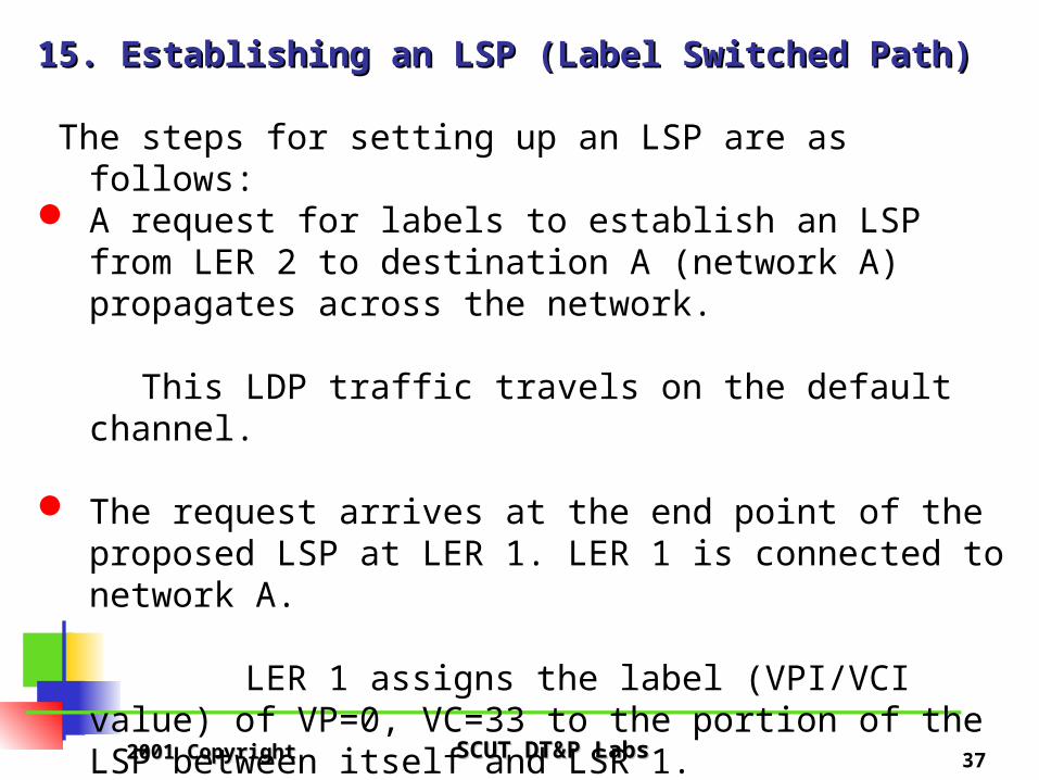
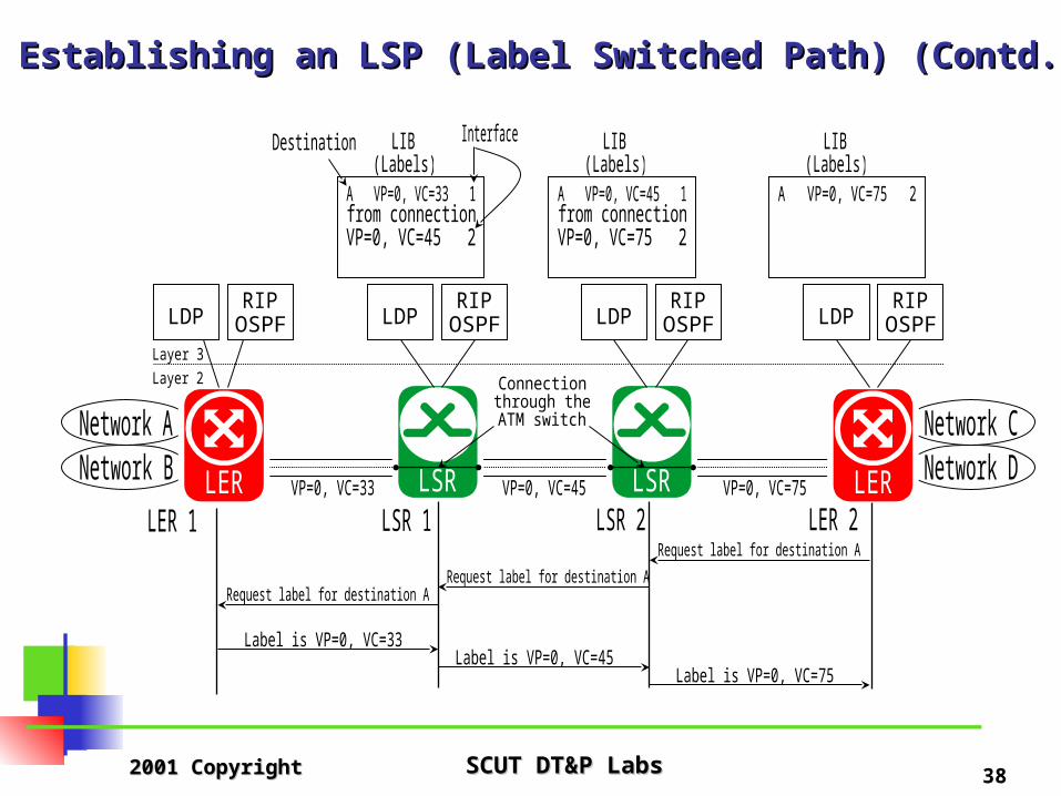
The steps for setting up an LSP are as follows: A request for labels to establish an LSP from LER 2 to
destination A (network A) propagates across the network.
This LDP traffic travels on the default channel.
The request arrives at the end point of the proposed LSP at LER 1. LER 1 is connected to network A.
LER 1 assigns the label (VPI/VCI value) of VP=0, VC=33 to the portion of the LSP between itself and LSR 1.
This label (VP=0, VC=33) is stored in the label information base (LIB) of LSR 1.
2001 Copyright 2001 Copyright SCUT DT&P LabsSCUT DT&P Labs 38
15. Establishing an LSP (Label Switched Path) (Contd.)15. Establishing an LSP (Label Switched Path) (Contd.)

2001 Copyright 2001 Copyright SCUT DT&P LabsSCUT DT&P Labs 39
15. Establishing an LSP (Label Switched Path) (Contd.)15. Establishing an LSP (Label Switched Path) (Contd.)
LSR 1 then assigns the label VP=0, VC=45 to the portion of the LSP between itself and LSR 2.
This label is stored in the LIBs of both LSR 1 and LSR 2. LSR 1 now has enough information to perform label
switching, that is, it has an incoming label (VP=0, VC=45) associated with an interface and an outgoing label (VP=0, VC=33) associated with another interface.

2001 Copyright 2001 Copyright SCUT DT&P LabsSCUT DT&P Labs 40
15. Establishing an LSP (Label Switched Path) (Contd.)15. Establishing an LSP (Label Switched Path) (Contd.)
LSR 2 assigns the label VP=0, VC=75 to the portion of the LSP between itself and LER 2.
This label is stored in the LIB of both LSR 2 and LER 2.
The network now has an LSP from LER 2 to LER 1. IP traffic destined for any networks connected to LER 1 (or to LER 1 itself) will travel along this LSP.

2001 Copyright 2001 Copyright SCUT DT&P LabsSCUT DT&P Labs 41
16. Link Failure16. Link Failure
An MPLS node periodically sends LDP keep-alive messages to its peer.
If LSP has not received either a keep-alive message or other LDP traffic from its peer within an agreed time, it times out and cancels the LDP session.
The LDP immediately signals down all affected LSPs regardless of their position in the network.

2001 Copyright 2001 Copyright SCUT DT&P LabsSCUT DT&P Labs 42
16. Link Failure (Contd.)16. Link Failure (Contd.)
Either the layer 3 routing protocols or the LDP notices a failed link. If the layer 3 routing protocols are first to notice, they inform the LDP. All LSPs which use this interface are signalled down and all information the LDP has learned from that LDP session is disregarded. If the LDP is the first to notice, it informs the routing software, and the software in turn updates the routing tables in each node.

2001 Copyright 2001 Copyright SCUT DT&P LabsSCUT DT&P Labs 43
16. Link Failure (Contd.)16. Link Failure (Contd.)
Following LSP failure, the MPLS node releases the LSP, then consults its routing tables for alternative routes and constructs other LSPs.
Additionally, the node which initiates the signalling to create an LSP periodically tries to reestablish that LSP when that LSP fails.
2001 Copyright 2001 Copyright SCUT DT&P LabsSCUT DT&P Labs 44
17. Loops17. Loops
Methods for dealing with loops can be split into three categories:
Loop survivalLoop survival
Loop detectionLoop detection
Loop preventionLoop prevention

2001 Copyright 2001 Copyright SCUT DT&P LabsSCUT DT&P Labs 45
17. Loops (contd.17. Loops (contd.Loop survivalLoop survival Loop survival makes use of methods which minimize the impact of loops, for example, by limiting the amount of network resources which can be consumed by a loop.
The most basic method for loop survival is based on the use of a TTL (Time To Live) field.
Neither ATM nor Frame Relay has a TTL field, so this method cannot be used for our purposes.
Another possible tool for loop survival is the use of fair queuing. This allows unrelated flows of user data to be placed in different queues. thereby minimizing the effect that loopingdata has on other data.

2001 Copyright 2001 Copyright SCUT DT&P LabsSCUT DT&P Labs 46
17. Loops (Contd.)17. Loops (Contd.) Loop detectionLoop detection Loop detection allows loops to be set up, but later detects these loops and eliminates them.
Loop detection may be achieved by using a path vector control message. A path vector contains a list of the LSRs visited by an LDP control packet.
Each LSR which propagates a control packet to either create or modify an LSP adds its own unique identifier to the path vector list.
An LSR that receives a message with a path vector that contains its own identifier detects that the message hastraversed a loop.

2001 Copyright 2001 Copyright SCUT DT&P LabsSCUT DT&P Labs 47
17. Loops (Contd.)17. Loops (Contd.) Loop preventionLoop prevention Loop prevention makes use of methods to ensure that loops are never set up at L2. One method of loop prevention requires that labels be propagated, starting at the egress LER and working backwards towards the ingress LER. This method, termed ‘ordered downstream on demand’ is the method used in the LSP set example given earlier in the chapter.

2001 Copyright 2001 Copyright SCUT DT&P LabsSCUT DT&P Labs 48
The End of MPLSThe End of MPLS