200 series meters - denver instrument · range 0.01 – 300,000 µs/cm• 30 - 20mΩ•cm* 0.01 -...
TRANSCRIPT

200 Series MetersOperation Manual
A S 7.001 pH
25.0°C
4.008 pH
7.000
6/30/1998 02:28 PM
Denver Instrument
S
902377.1 Rev. D

Models 215, 220, 225 and 250
Modes pH mV Temperature
Range -2.000 to 20.000 ±1800.0 -5.0 to 105.0˚C
Resolution 0.001/ 0.01 / 0. 1 0.1 / 1 0.1
Accuracy ±0.002 ±0.1 ± 0.3
Temperature Automatic & manual: -5 to 105˚CCompensation
Slope Control Automatic, 90 to 105%
Manual, 80 to 120%
Environmental 15 to 40°C, humidity from 0 to 90% (noncondensing)Conditions
Power Requirements 115V 50/60Hz (Additional voltages available)
Ordering Information
Meter with kit includes: Meter, power supply, high performance glass-body pH/ATC “3-in-1”
electrode, electrode arm and operation manual.
Meter only kit includes: Meter, power supply, electrode arm and operation manual.
Models 225 and 250
Mode Ion
Range 1.00E-9 to 9.99E9
Resolution 1, 2, or 3 significant figures
Accuracy ± 0.17%n (n = ion charge)
Slope Control Automatic or manual, 5.9 mV/decade (10% slope)to 71 mV/decade (120%)
Models 220 and 250
Practical NaCl
Mode Conductivity Resistivity Salinity Salinity TDS
Range 0.01 – 300,000 µS/cm• 30 - 20MΩ•cm* 0.01 - 42 ppt* 0.01 - 70ppt* 0.005 - 150,000*
Resolution 1, 2, 3, or 4 significant figures
Accuracy ± 0.5% ±0.01µS/cm
Cell Constant Automatic or manual, 0.01 - 100 /cm
Temperature Coeff Off or On (0 - 4% /°C)
Number of Standards 5
*depending on cell constant (from 0.1 to 10 /cm)
Meter Specifications

Meter Specifications . . . . . . . . . . . . . . . . . . . . . . . . . . . . . . . . . . inside front coverQuick Start Guide for pH Measurement . . . . . . . . . . . . . . . . . . . . . . . . . . . Page iiIntroduction
Menu Keys, Softkeys and Display . . . . . . . . . . . . . . . . . . . . . . . . . . . . . . . . . . 1Electrode Connectors and Inputs . . . . . . . . . . . . . . . . . . . . . . . . . . . . . . . . . . . 2LCD Display . . . . . . . . . . . . . . . . . . . . . . . . . . . . . . . . . . . . . . . . . . . . . . . . . . . 3Function Keys . . . . . . . . . . . . . . . . . . . . . . . . . . . . . . . . . . . . . . . . . . . . . . . . . . 4
Electrodes
Preparing pH and Ion Selective Electrodes . . . . . . . . . . . . . . . . . . . . . . . . . . . 6Connecting Electrodes . . . . . . . . . . . . . . . . . . . . . . . . . . . . . . . . . . . . . . . . . . . 6Using and Storing Electrodes . . . . . . . . . . . . . . . . . . . . . . . . . . . . . . . . . . . . . . 7
pH Electrodes . . . . . . . . . . . . . . . . . . . . . . . . . . . . . . . . . . . . . . . . . . . . . . . . 7Solid-State FET Electrodes . . . . . . . . . . . . . . . . . . . . . . . . . . . . . . . . . . . . . . 7Ion Selective Electrodes . . . . . . . . . . . . . . . . . . . . . . . . . . . . . . . . . . . . . . . . 7
Meter Setup
Meter Setup Menu . . . . . . . . . . . . . . . . . . . . . . . . . . . . . . . . . . . . . . . . . . . . . . 8pH Mode
pH Mode Standardization Menu. . . . . . . . . . . . . . . . . . . . . . . . . . . . . . . . . . . . 9Cal Reminder Menu . . . . . . . . . . . . . . . . . . . . . . . . . . . . . . . . . . . . . . . . . . . . . 9Select Custom Buffer Set . . . . . . . . . . . . . . . . . . . . . . . . . . . . . . . . . . . . . . . . . 9pH Mode Options Menu . . . . . . . . . . . . . . . . . . . . . . . . . . . . . . . . . . . . . . . . . 10Standardizing and Measuring pH . . . . . . . . . . . . . . . . . . . . . . . . . . . . . . . . . . 12Clearing Buffers. . . . . . . . . . . . . . . . . . . . . . . . . . . . . . . . . . . . . . . . . . . . . . . . 12
mV Mode
mV Mode Standardization Menu . . . . . . . . . . . . . . . . . . . . . . . . . . . . . . . . . . 13mV Mode Options Menu. . . . . . . . . . . . . . . . . . . . . . . . . . . . . . . . . . . . . . . . . 13Clearing Relative mV Mode . . . . . . . . . . . . . . . . . . . . . . . . . . . . . . . . . . . . . . 13
Quick Start Guide for Ion Measurement. . . . . . . . . . . . . . . . . . . . . . . . . . . . . . . 14Ion Mode
Ion Mode Standardization Menu . . . . . . . . . . . . . . . . . . . . . . . . . . . . . . . . . . 15Standardizing and Measuring Ion. . . . . . . . . . . . . . . . . . . . . . . . . . . . . . . . . . 16Measuring Ion using a Known Addition type (incremental ion) method . . . 17
Quick Start Guide for Conductivity/Resistivity/Salinity/TDS Measurement . . 18Conductivity/Resistivity/Salinity/TDS Modes
Conductivity/Resistivity/Salinity/TDS Standardize Menu . . . . . . . . . . . . . . . . 19Conductivity/Resistivity/Salinity/TDS Options Menu . . . . . . . . . . . . . . . . . . . 20
Quick Start Guide for Coulometric Karl Fischer Titration . . . . . . . . . . . . . . . . . 21Karl Fischer Titrator Setup . . . . . . . . . . . . . . . . . . . . . . . . . . . . . . . . . . . . . . . . . 22Karl Fischer Titration Mode . . . . . . . . . . . . . . . . . . . . . . . . . . . . . . . . . . . . . . . . . 24
Running a Titration . . . . . . . . . . . . . . . . . . . . . . . . . . . . . . . . . . . . . . . . . . . . . 24Titrator Status and Operating Data. . . . . . . . . . . . . . . . . . . . . . . . . . . . . . . . . 25Titrator Setup Menu . . . . . . . . . . . . . . . . . . . . . . . . . . . . . . . . . . . . . . . . . . . . 26
Cleaning the Titration Cell. . . . . . . . . . . . . . . . . . . . . . . . . . . . . . . . . . . . . . . . . . 27Troubleshooting Karl Fischer Titration . . . . . . . . . . . . . . . . . . . . . . . . . . . . . . . . 29Modifying Titration Protocols . . . . . . . . . . . . . . . . . . . . . . . . . . . . . . . . . . . . . . . 30Data logging . . . . . . . . . . . . . . . . . . . . . . . . . . . . . . . . . . . . . . . . . . . . . . . . . . . . 31Troubleshooting. . . . . . . . . . . . . . . . . . . . . . . . . . . . . . . . . . . . . . . . . . . . . . . . . . 32pH Theory . . . . . . . . . . . . . . . . . . . . . . . . . . . . . . . . . . . . . . . . . . . . . . . . . . . . . . 33Understanding Conductivity Temperature Correction . . . . . . . . . . . . . . . . . . . . 34Understanding pH Temperature Compensation. . . . . . . . . . . . . . . . . . . . . . . . . 35Ion Selective Electrode Theory . . . . . . . . . . . . . . . . . . . . . . . . . . . . . . . . . . . . . . 35Determining Isopotential Point . . . . . . . . . . . . . . . . . . . . . . . . . . . . . . . . . . . . . . 36RS-232 Serial Interface Meter Command Set . . . . . . . . . . . . . . . . . . . . . . . . . . . 37Maintenance . . . . . . . . . . . . . . . . . . . . . . . . . . . . . . . . . . . . . . . . . . . . . . . . . . . . 39Menu Tree Diagrams . . . . . . . . . . . . . . . . . . . . . . . . . . . . . . . . . . . . . . . . . . . . . . 40Warranty Instructions. . . . . . . . . . . . . . . . . . . . . . . . . . . . . . . . . Inside Back Cover
Table of Contents

1. Connect power cable to meter connector on therear panel marked “power” and to AC powersource.
2. Connect the glass pH/ATC electrode to the chan-nel A BNC connector marked “ch.A” and to thechannel A temperature connector marked “tempA”.
3. Verify the meter is in pH mode on channel A. Usethe Mode key and Channel key to set the meter tothe correct mode and channel if necessary. (SeeFunction keys).
4. Standardize the electrode by immersing the elec-trode in a buffer, pressing Standardize, pressing1) Auto-enter a buffer and following the prompts.Repeat this step to enter each buffer. The meterwill check the electrode and buffers, and give anerror message if there is a problem.
Press Standardize to enter or clear buffers, selectbuffers, set resolution, or set other parameters forthe current mode and channel.
5. The display shows the current measurement, andindicates a stable reading with the indicator.Press Cal Data to review and graph the electrodecalibration data.
ii
Quick Start Guide for pH Measurement
ch. A
ref. A
ch
Temp. A Temp. B
RS232C
power
cond. C
ch. A
ref. A
ch
Temp. A Temp. B
RS232C
power
cond. C
A 7.000 pH
25.0°C
No buffers.
6/30/1998 02:28 PM
Mode
Channel A: pH mode
Standardize Menu
1) Auto-enter a buffer
2) Manual buffer entry
3) Clear buffers
4) Options menu
5) Cal reminder menu
6) Select buffer set
channel
indicator
units
indicatorChannel
Standardize
A 7.000 pH
25.0°C
4.008 pH7.000
6/30/1998 02:28 PMentered
buffers
“power”
“ch. A” “temp A”
s
s
stability
indicator
s

This Denver Instrument electrochemistry meter is a powerful, versatile and accu-rate instrument. It features easy menu-based operation with easy to understandprompts and electrode/standard error checking.
These meters feature many advanced options, such as programmable stability cri-teria, programmable standardization reading delay times, multi-channel operation,fast reading update rates of twice per second for all channels, programmablealarms, programmable data logging of 500 data points and a superb RS-232 serialinterface for controlling the meter and obtaining data.
Direct Menu Keys, Softkeys and Display
The meter uses six Direct Menu keys to access the menus and operations (such asselecting pH mode, standardizing, checking electrode calibration data, selectingthe electrode channel).
There are four Softkeys that provide additional operations; these Softkeys changetheir function as needed and each Softkey has an icon to indicate its current func-tion.
The display is a backlit quarter-VGA screen capable of displaying all four electrodechannels of a Model 250 and eight channels (four electrode channels and four KarlFischer titrators) for a Model 270 simultaneously. The backlight will turn off after aperiod of non-use (the default is 45 minutes, set this time in the Setup menu);pressing any key will automatically turn the display backlight on again.
A S 7.001 pH
25.0°C
4.008 pH
7.000
6/30/1998 02:28 PM
Denver Instrument
S
1
Introduction
Softkeys
Direct Menu
KeysDirect Menu
Keys Numeric
Keypad

Electrode Connectors and Inputs
BNC ("ch.A" or "ch.B") connectors: pH, IonSelective Electrodes and ORP (redox) elec-trodes attach to the meter through a BNC("round twist-on") connector to channel A orchannel B (Models 225 and 250 only).
Temperature ("temp A" or "temp B") connec-
tors: use to connect the 2.5mm mini-phoneplug from the temperature sensor (built intothe pH electrode with the Denver Instrumentstandard pH/ATC electrode) for AutomaticTemperature Compensation (ATC).
Reference ("ref.A" or "ref.B") connectors: usefor attaching a reference electrode tip-pin plugwhen a separate reference electrode is used.
Conductivity DIN (“ch.C conductivity”)
connector: use to connect a 4-band conductivi-ty/ATC cell. These 4-band cells offer improvedlinearity and stability over older 2-band con-ductivity cells. (Models 220 and 250 only).
FET DIN ("ch.F FET") connector: use to con-nect the Denver Solid-State Field EffectTransistor (FET) pH/ATC electrode. These non-glass pH electrodes offer certain advantagesover conventional glass pH electrodes.
Serial port ("RS232") DB-9 connector: use toconnect a serial printer or Personal Computer.This bi-directional interface outputs data andreceives meter commands.
Power (“power”) connector: use to connect a5.5mm OD x 2.1 ID coaxial connector with12VDC at 500mA (center pin negative).
Titrator Network (“titrator network”) connec-
tor: use to connect up to four Coulometric KarlFischer titrators.
2
Introduction
ch. A
ref. A
tempA
RS232C
power
ch. FFET
ref
Connectors for Model 250
Note: Not all models have allconnectors shown.

D
Note: Not all of the following will display at thesame time.
A Result: current measurement.
B Units: displays the units for the current mea-surement. Examples: pH, mV, mg/L F-, µS/cmor Ω-cm.
C Softkey icons: show the current functionassigned to each softkey.
D Calibration due reminder: the icon meansa calibration is now due.
E Date and time: displayable in different formats.
F Datalogging: the icon indicates datalog-ging is active.
G Buffers/Standards: in single channel mode, allentered buffers or standards are displayed. A“!” symbol beside a buffer indicates that bufferis out of the entered calibration valid time (SeeCalibration reminder, page 9).
H Temperature: displays the measured tempera-ture when an electrode with ATC or separatetemperature probe is attached. Shows “M”when a manually entered temperature is beingused.
I Alarm: “*” indicator means data is outside theset alarm limits.
J Channel: indicates which electrode channel(input) or titrator channel is being displayed.Channels A & B are BNC electrode inputs,Channel C is a conductivity cell input, andChannel F is a FET pH electrode input. ChannelsT1 through T4 are Karl Fischer (KF) titrators(Models 260 & 270).
K Stability: the indicates the electrode is stableto the selected criteria.
L Multiple Channel: display can show two (Model215), three (Models 220 and 225) or four (Model250) electrode measurements with temperaturesimultaneously. Models 260 and 270 can displayfour KF titrators simultaneously.
M Out-of-range or non-valid reading: dashes indi-cate a measurement is not available. This usual-ly means the reading is out of range, or canmean in ion mode that no standards have beenentered, or strict calibration has been set andthe calibration expired. 3
Display
* A 7.000 pH
25.0°C
4.008 pH7.0009.999
6/30/1998 02:28 PM
A B
J
I
H
G
E
C
Single channel display
K
F
A 6.998 pH
24.6°C
B 1.02 mg/L
23.4°C F-
30-6-1998 14:28:05
Dual channel display
L
A pH
23.8°C
1998.6.30 14:28:30
M
s
s
s
LOG
CAL!
CAL!
LOG
S

A Mode: Selects the mode: pH, mV (Model215), Ion (Models 225 and 250),Conductivity - Resistivity-NaCl Salinity-Practical Salinity-TDS (Models 220 and250) to use for the currently selected chan-nel (electrode input). Select KF protocol forselected titrator (Models 260 and 270).
B Standardize: Enters buffers or standardsfor the currently selected channel andmode. Use to enter pH buffers, relative mVoffset, ion standards or conductivity /resis-tivity standards. Use to modify a KF titra-tion protocol.
Also used to change other settings whichaffect the measurement.
C Cal Data: Displays and graphs buffers orstandards with time and date stamp andelectrode calibration data for the selectedchannel and mode. Shows KF titrator oper-ating data such as drift rate, reagent condi-tion, and statistics on the last titrations.
D Channel: Selects the channel(s) (electrodeinputs) to display. The Model 215 can dis-play one or two channels simultaneously(Channels A and F). The Model 225 candisplay one, two or three channels simulta-neously (Channels A, B and F). The Model220 can display up to three channels(Channels A, C and F). The Model 250 candisplay up to four channels (Channels A, B,C and F). Models 260 and 270 can displayup to four KF Titrator channels.
E Setup: The Setup menu is used to set vari-ous general meter settings, such as dateand time, display contrast, keypress beepand serial port. Use Titration setup menuto access titration protocols and controltitrators.
F Data Log: Displays the datalogging menuused to set datalogging and view thestored Data Log (see Datalogging).
G Clear: Exits from the current menu andreturns to the previous menu, cancels thecurrent operation or clears a number entry.
H Enter/Print: Accepts numeric values, menuselections or pending operations. In themain measure screen, acts as a Print key,sending all current measurements to aprinter/ computer through the serial portand stores the measurements in the DataLog.
I Softkeys: These four keys access differentoperations at different times. Most menusoffer a “Help” softkey and the “Measure”softkey, which allows a direct return to themain measuring screen, exiting all menusimmediately. The “Up Arrow” and “DownArrow” softkeys offer one way to select amenu item. The “Left Arrow” key is a back-space, active during number entry.
J Numeric Keys: Pressing a number keyselects a numbered item in a menu. Thenumber keys also allow entering values forbuffers, standards, and various meter set-tings.
4
Function Keys
E
–+
Help
Measure
Scroll up
Scroll down
Backspace
Graph
Exponent number entry
Incremental ion method
Measure lock
Measure unlock
Titrator Start/Stop
Softkeys
5
Function Keys
Mode
Standardize
Cal Data
Channel Enter/Print
Clear
Setup
Data Log
?
A
B
C
D
E
F
G
H
I
J
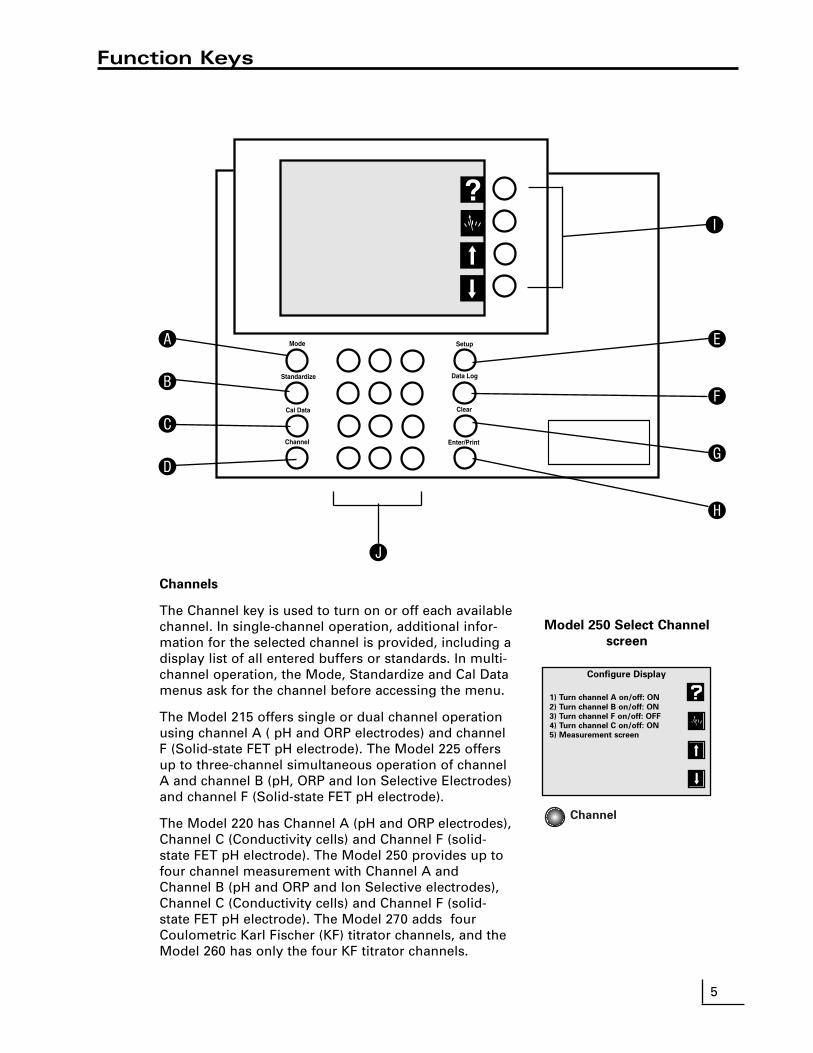
Channels
The Channel key is used to turn on or off each availablechannel. In single-channel operation, additional infor-mation for the selected channel is provided, including adisplay list of all entered buffers or standards. In multi-channel operation, the Mode, Standardize and Cal Datamenus ask for the channel before accessing the menu.
The Model 215 offers single or dual channel operationusing channel A ( pH and ORP electrodes) and channelF (Solid-state FET pH electrode). The Model 225 offersup to three-channel simultaneous operation of channelA and channel B (pH, ORP and Ion Selective Electrodes)and channel F (Solid-state FET pH electrode).
The Model 220 has Channel A (pH and ORP electrodes),Channel C (Conductivity cells) and Channel F (solid-state FET pH electrode). The Model 250 provides up tofour channel measurement with Channel A andChannel B (pH and ORP and Ion Selective electrodes),Channel C (Conductivity cells) and Channel F (solid-state FET pH electrode). The Model 270 adds fourCoulometric Karl Fischer (KF) titrator channels, and theModel 260 has only the four KF titrator channels.
Configure Display
1) Turn channel A on/off: ON
2) Turn channel B on/off: ON
3) Turn channel F on/off: OFF
4) Turn channel C on/off: ON
5) Measurement screen
Model 250 Select Channel
screen
Channel

The meter allows you to use a variety of glass mem-brane (“glass”) pH/ATC electrodes, ion selective elec-trodes, Conductivity/ATC cells, the Denver InstrumentField Effect Transistor (FET) Solid-State pH/ATC elec-trode, temperature (ATC) probes, combination elec-trodes using a BNC connector, or separate electrodepairs with BNC connector and reference pin.
Preparing Electrodes and Conductivity Cells
Remove the wetting cap or storage cap from the elec-trode. Before first using your pH electrode or wheneverthe electrode is dry, soak it several hours in an electrodefilling or storage solution (3 Molar KCl solution) or in abuffer for pH electrodes. Condition ISE’s in the recom-mended solutions. Rinse Conductivity cells with deion-ized water before use.
Connecting Electrodes
pH, ORP or ISE electrodes (with BNC connector):
Connect the electrode to the BNC input, either channelA or channel B (Models 225 and 250 only), located at therear of the meter. Push in and rotate the electrode’s BNCconnector until it locks in place. Connect the ATC con-nector to the temp. A or temp. B connector. To discon-nect, twist the BNC connector in the opposite directionand pull.
Electrode Pair Using a Reference Electrode (with
Reference Pin Plug):
Connect the indicating electrode to the BNC input.Connect the reference electrode to the Reference input.Push the electrode’s tip pin plug into the input to con-nect and pull out to disconnect.
Conductivity Cells (with DIN connector):
Align and push in the DIN connector fully to the channelC input (Models 220 and 250 only). Pull carefully to dis-connect.
6
Electrodes
To measure Use channel (connector)
pH A (BNC)* or B (BNC)*mV (ORP) A (BNC)* or B (BNC)*ion (ISE) A (BNC)* or B (BNC)*Conductivity C (DIN)Resistivity C (DIN)Salinity C (DIN) TDS C (DIN)pH (FET) F (mini-DIN)
*Separate reference electrodes can be used with “Ref A” or“Ref B” connectors
ch. A
ref. A
tempA
ref
ch. FFET
ch. Cconductivity
BNC Connector
Channel CConductivity Input
ATC Connector
Channel FFET pH Input
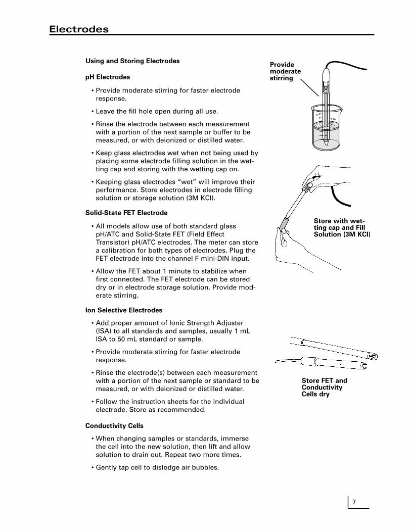
Using and Storing Electrodes
pH Electrodes
• Provide moderate stirring for faster electroderesponse.
• Leave the fill hole open during all use.
• Rinse the electrode between each measurementwith a portion of the next sample or buffer to bemeasured, or with deionized or distilled water.
• Keep glass electrodes wet when not being used byplacing some electrode filling solution in the wet-ting cap and storing with the wetting cap on.
• Keeping glass electrodes “wet” will improve theirperformance. Store electrodes in electrode fillingsolution or storage solution (3M KCl).
Solid-State FET Electrode
• All models allow use of both standard glasspH/ATC and Solid-State FET (Field EffectTransistor) pH/ATC electrodes. The meter can storea calibration for both types of electrodes. Plug theFET electrode into the channel F mini-DIN input.
• Allow the FET about 1 minute to stabilize whenfirst connected. The FET electrode can be storeddry or in electrode storage solution. Provide mod-erate stirring.
Ion Selective Electrodes
• Add proper amount of Ionic Strength Adjuster(ISA) to all standards and samples, usually 1 mLISA to 50 mL standard or sample.
• Provide moderate stirring for faster electroderesponse.
• Rinse the electrode(s) between each measurementwith a portion of the next sample or standard to bemeasured, or with deionized or distilled water.
• Follow the instruction sheets for the individualelectrode. Store as recommended.
Conductivity Cells
• When changing samples or standards, immersethe cell into the new solution, then lift and allowsolution to drain out. Repeat two more times.
• Gently tap cell to dislodge air bubbles.
7
Electrodes
Store with wet-ting cap and FillSolution (3M KCl)
Providemoderatestirring
Store FET andConductivityCells dry

Meter Setup Menu
Press Setup to access the Meter Setup menu:
1. Time and date menu: use to set the time format (HH:MMAM/PM or HH:MM:SS), set the time, set the date format(MM/DD/YY, DD-MM-YY or YYYY.MM.DD), and set thedate.
2. Select temperature units: use to select temperature mea-surement and display in degrees Celsius, degreesFahrenheit or Kelvin.
3. Select contrast: use to select the display contrast, makingthe displayed characters lighter or darker. Select setting“5” for typical conditions.
4. Select baud rate: use to set the serial RS232 port baudrate. This must match the baud rate setting of the printeror computer being used with the meter. Titration setup
menu (Models 260 & 270): use to modify, select and printtitration protocols, set titration intermediate results print-out, select balance type for the titrators, and control titra-tion stirrers.
5. Setup serial port: use to configure the serial port startbits and parity setting. This must match the settings ofthe printer or computer being used with the meter. Serial
port menu (Models 260 & 270): use to set serial port baudrate, start bits and parity.
6. Keypress beep on/off: use to turn on or off a "beep"upon each keypress as an audible signal that a key hasbeen pressed.
7. Select video color scheme: use to set the display to blackcharacters on a white background or white characters ona black background.
8. Show meter information: use to show the meter model,software version and serial number.
9. Enable measure lock: use to enable the measure lockwhere a stable measurement is locked (frozen) for laterreview. Stability criteria should be set to SLOW for allchannels and modes in use.
0. Enable strict calibration: use to set strict calibrationwhere no measurements are displayed if the calibrationreminder has expired.
“±” Set screen saver timeout: use to set a time for the back-light to turn off and the screensaver to activate.
"•" Restore factory defaults: use to reset all settings to fac-tory defaults. On occasion it may be useful to completelyreset the meter, for example, if other users have changeda setting.
Warning!
A reset also clears all electrode standardizations.
8
Meter Setup
!
Meter Setup Menu
1) Time and date menu
2) Select temperature units
3) Select contrast
4) Select baud rate
5) Setup serial port
6) Keypress beep on/off
7) Select video color scheme
8) Show meter information
9) Enable measure lock
0) Enable strict calibration
±) Set screen saver timeout
•) Restore factory defaults
Setup
Select Time Format
1) hr : min : sec
2) hr : min AM/PM
Select Date Format
1) mm / dd / yyyy
2) dd – mm – yyyy
3) yyyy.mm.dd
Enable Measure Lock
Display lock/unlock softkey?
1) Yes
2) No
If “measure lock” is enabled, a
“lock” soft key will appear on
the measurement screen
Enable Strict Calibration
Require calibration?
1) Yes
2) No
If strict calibration is enabled,
no measurements will be
displayed for a channel with an
expired cal reminder.

9
pH Mode
pH Mode Standardize Menu
Press Mode and select 1) pH. Press Standardize and the pH Mode Standardize Menuappears:
1. Auto-enter a buffer: use to add a new buffer whichis auto recognized by the meter, or update an exist-ing buffer. Follow the prompts.
2. Manual buffer entry: use to enter a buffer value bymanually entering the pH of the buffer.
3. Clear buffers: use to clear all buffers entered for thecurrent channel (pH mode). If all entered buffers arebeing re-entered, it is usually not necessary to clearbuffers before re-entering them.
4. Options Menu: A menu of additional specific pHmode settings. (See page 10).
5. Cal reminder menu: use to set a timer remindingyou to recalibrate. A icon will appear on themain screen and an exclamation mark will appearbeside the buffers for which time has expired.
The calibration reminder is a reminder of when elec-trode calibration (with buffers) should be redone. Itis based on elapsed time from the oldest enteredbuffer.
If strict calibration is set (see Meter Setup Menu), whena calibration has expired the icon appears, and "-- - " is displayed in place of the measurement. No mea-surements can be obtained until a calibration is per-formed.
Note: When strict calibration is set, the calibrationreminders for all channels are turned ON, and can't beturned off from the Cal Reminder Menu.
6. Select buffer set: There are five auto-recognitionbuffer sets and the option to configure and use acustom buffer set of your own.
Select custom buffer set
Use Custom Buffer Set to make a set of buffers con-taining the specific buffers in use (up to five buffers).Select Custom Buffer Set, configure the custombuffer set, then buffers from this set will be automat-ically recognized and entered.
Custom buffers can have any numeric pH value, orcan be selected from the built-in temperature cor-rected buffers. Using the built-in buffers allow tem-perature correction of the pH values of the buffers,offering more accuracy.
Channel A: pH mode
Standardize Menu
1) Auto-enter a buffer
2) Manual buffer entry
3) Clear Buffers
4) Options Menu
5) Cal reminder menu
6) Select buffer set
Standardize
Channel A: pH mode
Manual Buffer Entry
Enter the actual pH of this
buffer, after correcting
for temperature:
pH
Press Enter to accept.
Channel A: pH mode
Cal Reminder Menu
1) Turn reminder On/Off: OFF
2) Set reminder interval:
01, 00 : 00 days, hr : min
3) Standardization menu
When the cal reminder expires, a “CAL!”
(or “!”) icon will be displayed with the
measurement and with each expired stan-
dard. If strict cal is ON, reminders are
always ON, and expired channels show no
measurements.
Channel A: pH mode
Select Buffer Set
1) 2, 4, 7, 10, 12 at 25C
2) 2, 4, 7, 10, 12 at 20C
3) 1, 3, 6, 8, 10, 13
4) 1.68, 4.01, 6.86, 9.18, 12.46
5) 1.09, 3.06, 4.65, 9.23, 12.75
6) Select custom buffer set
Custom Buffer
No buffers
CAL!
Channel A: pH mode
Configure Custom Buffer Set
1) Add a “built-in” buffer
2) Add a manual buffer
3) Delete a buffer
4) Standardize menu
Custom Buffer Set
No buffers
CAL!

pH Mode Options Menu
1. Select resolution: use to set pH readings to 0.1, 0.01,or 0.001 pH units.
2. Select stability criteria: use to set stability criteria toslow, medium or fast to match the electrode's speedof response and the variability of the signal allowedfor a “stable” ( ) measurement.
3. Select signal averaging: use to set filtering of the elec-trode signal to very slow (10 readings), slow (8), medi-um (6), fast (4) or very fast (2). Slower settings givemore stable readings, although may require longertimes to reach stability.
4. Set standardization delay: use to set a reading delaytime for the meter to wait before accepting an elec-trode signal during standardization. Programming astandardization reading delay helps slow respondingelectrodes reach equilibrium before the electrode sig-nal is accepted.
5. Set pH slope: use to set a known electrode slope usedby the meter with a zero- or single-point standardiza-tion. The normal default slope is 59.16 mV/pH. Themeter allows between 80 and 120 % efficiency to beentered.
6. Standardize menu: Returns to the pH modeStandardization Menu.
7. Manual temperature menu: use to set a temperatureto be used in the absence of an ATC probe or whenmanually overriding the ATC.
8. Data alarm menu: use to set pH limits. If the limits areexceeded an alarm indication (“*”) is displayed andrecorded with any data points placed in the Data Log.
9. Set isopotential point: use to set an isopotential pointfor use in high accuracy electrode measurements (SeeIsopotential, page 20).
10
pH Mode
Channel A: pH mode
Options Menu
1) Select resolution
2) Select stability criteria
3) Select signal averaging
4) Set standardization delay
5) Set pH slope
6) Standardize menu
7) Manual temperature menu
8) Data alarm menu
9) Set isopotential pointS

Notes:
1. Auto-recognized buffers are found in the auto-recog-nized built-in buffer sets. These buffers are auto-rec-ognized by the meter, and are also automatically tem-perature corrected for the variation of buffer pH withtemperature.
2. When manually entering buffers, the exact pH of thebuffer at the current temperature must be entered. Allbuffers change pH with temperature. For best accura-cy, either use the built-in buffers or make sure manu-ally entered buffers are at the expected temperature(so that their pH as entered is correct).
3. Auto-recognition Buffer Sets: 1) 2, 4, 7, 10, 12 (nominal value adjusted at 25°C)2) 2, 4, 7, 10, 12 (nominal value adjusted at 20°C)3) 1, 3, 6, 8, 10, 134) 1.68, 4.01, 6.86, 9.18, 12.46 (NIST buffers)5) 1.09, 3.06, 4.65, 9.23, 12.75 (DIN buffers)6) Select custom buffer set
4. Temperature Correction of Electrodes and Buffers
The meter automatically compensates for the tempera-ture dependence of the electrode's response when mea-suring pH. The meter also compensates for bufferchange in pH value with temperature. See“Understanding pH Temperature Compensation” onpage 35 .
Using a Solid-state FET (Field Effect
Transistor) pH/ATC Electrode
By turning channel F (FET) on, a Denver Instrument FETpH/ATC electrode can be directly used. pH and mVmodes are available with the FET electrode. FET devicescan have large offset potentials that vary with each tran-sistor chip, so Manual buffer entry must be used toenter the first buffer. After one buffer has been enteredusing “Manual buffer entry”, following buffers can usu-ally be entered with “Auto-enter a buffer”.
pH Mode
11

12
Standardizing and Measuring pH
1. Immerse the electrode in a buffer and stir moderately.The meter displays the current pH measurement.
2. Allow the electrode sufficient time to reach equilibrium.
3. Press Standardize, then press either 1) Auto-enter a
buffer or 2) Manual buffer entry.
4. Follow the prompts on the display.
5. The meter waits for a stable signal, automatically rec-ognizes the buffer (if using “Auto-enter”), checks theelectrode and buffer and enters the buffer. Theentered buffer appears in the display.
6. Alternatively, if the signal is not stable, you can pressEnter when the reading stabilizes according to yourtolerance criteria. The meter then enters the buffer.
7. Repeat steps 1 through 4 to enter a second, third,fourth or fifth buffer. With more than one buffer themeter performs a diagnostic check on the electrode.The electrode is considered good if the slope isbetween 90 to 105%. If a sixth buffer is entered, thebuffer farthest away is replaced by the new buffer.
Hints to achieve better accuracy:
• During standardization, allow time for the electrode tostabilize before entering the buffer into the meter.
• Standardize using at least two buffers, bracketing theexpected pH of your samples.
• Standardize at least daily for the most accurate read-ings.
• Open the Fill Hole on the electrode.• Stir all buffers and samples.• Rinse the electrode with DI water between samples
and buffers.• Always use fresh buffers.
Clearing Buffers
Press Standardize, then press 3) Clear buffers to clearbuffers. If all previously entered buffers will be re-entered, it is not necessary to clear buffers since themeter will replace the previous values. If re-enteringonly some buffers, all the old buffers should be cleared.
Channel A: pH mode
pH Checklist
Prepare buffer or sample.
Rinse electrode.
Place electrode in solution.
Stir moderately.
Press Enter to continue.
Channel A: pH mode
Standardize Menu
1) Auto-enter a buffer
2) Manual buffer entry
3) Clear buffers
4) Options menu
5) Cal reminder menu
6) Select buffer set
Standardize
Channel A: pH mode
Manual Buffer Entry
Enter the actual pH of this
buffer, after correcting
for temperature:
pH
Press Enter to accept.
mV
4 7 10pH buffers
samples

Ele
ctro
de
Po
ten
tial
, mV
Titrant Volume, mL
Redox Titration
Standardize
Millivolt measurements are used to measure ORP (oxi-dation-reduction potential) or redox potential, to checkperformance of pH or Ion Selective Electrodes, and forredox titrations.
The meter will measure millivolts (mV) by pressingMode and selecting 2) mV. Relative mV can be mea-sured by entering a mV offset or using the current mVvalue as the mV offset.
mV Standardization Menu
In mV mode, press Standardize and the mV modeStandardization Menu appears:
1. Auto-enter mV offset: use to set the relative mV off-set equal to the current mV reading. The current mVbecomes 0.0 relative mV.
2. Set mV offset: use to manually enter a mV offset.3. Clear mV offset: use to clear any offset that has been
entered, returning the meter to absolute mV mode.4. Options menu: a menu of additional settings specific
to the mV mode. See below.
mV Mode Options Menu
1. Select resolution: use to set mV readings to 1 or 0.1millivolt resolution.
2. Select stability criteria: use to select stability criteriafor slow, medium or fast response which use a tight,average or loose requirement to indicate a “stable”( ) reading.
3. Select signal averaging: use to set the meter to aver-age readings that are very slow (10 readings), slow(8), medium (6), fast (4) or very fast (2).
4. Set standardization delay: use to set a length of timefor the meter to wait before entering a relative mVstandardization.
5. Set mV offset: use to manually enter a mV offset(same as in the mV Standardize menu).
6. Standardization menu: returns to the mVStandardization Menu.
Clearing Relative mV Mode
Press Standardize, then press 3) Clear mV offset toclear offset and return the meter to absolute mV mode.
mV Mode
Channel A: mV mode
Standardize Menu
1) Auto-enter mV offset
2) Set mV offset
3) Clear mV offset
4) Options menu
Channel A: mV mode
Options Menu
1) Select resolution
2) Select stability criteria
3) Select signal averaging
4) Set standardization delay
5) Set mV offset
6) Standardize
13
S
14
Quick Start Guide for Ion Measurements
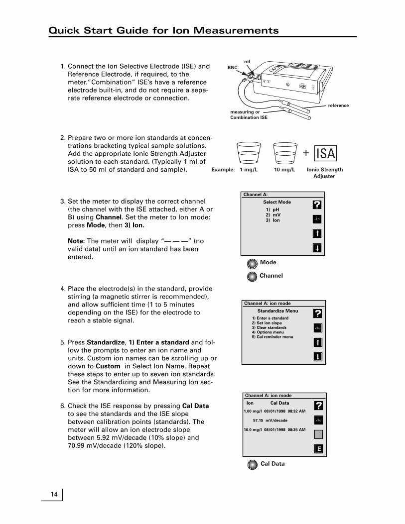
1. Connect the Ion Selective Electrode (ISE) andReference Electrode, if required, to themeter.”Combination” ISE’s have a referenceelectrode built-in, and do not require a sepa-rate reference electrode or connection.
2. Prepare two or more ion standards at concen-trations bracketing typical sample solutions.Add the appropriate Ionic Strength Adjustersolution to each standard. (Typically 1 ml ofISA to 50 ml of standard and sample),
3. Set the meter to display the correct channel(the channel with the ISE attached, either A orB) using Channel. Set the meter to Ion mode:press Mode, then 3) Ion.
Note: The meter will display “— — —” (novalid data) until an ion standard has beenentered.
4. Place the electrode(s) in the standard, providestirring (a magnetic stirrer is recommended),and allow sufficient time (1 to 5 minutesdepending on the ISE) for the electrode toreach a stable signal.
5. Press Standardize, 1) Enter a standard and fol-low the prompts to enter an ion name andunits. Custom ion names can be scrolling up ordown to Custom in Select Ion Name. Repeatthese steps to enter up to seven ion standards.See the Standardizing and Measuring Ion sec-tion for more information.
6. Check the ISE response by pressing Cal Data
to see the standards and the ISE slopebetween calibration points (standards). Themeter will allow an ion electrode slopebetween 5.92 mV/decade (10% slope) and70.99 mV/decade (120% slope).
ch. A
ref. A
ch
Temp. A Temp. B
RS232C
power
Mode
Channel
+ ISAExample: 1 mg/L 10 mg/L Ionic Strength
Adjuster
BNC
ref
measuring or
Combination ISE
reference
Cal Data
Channel A:
Select Mode
1) pH2) mV3) Ion
Channel A: ion mode
Ion Cal Data
1.00 mg/l 08/01/1998 08:32 AM
57.15 mV/decade
10.0 mg/l 08/01/1998 08:35 AM
E
Channel A: ion mode
Standardize Menu
1) Enter a standard
2) Set ion slope
3) Clear standards
4) Options menu
5) Cal reminder menu

Ion Mode Standardization Menu
Select channel A or B. Press Mode and then press 3) Ion for ionmode. Press Standardize and the Ion Mode Standardize Menuappears.
1. Enter a standard: use to add a new standard or update (re-enter) an existing standard. Follow the prompts. With the firststandard you select the ion name and units. Use Custom toenter an ion name.
2. Set ion slope: use to manually enter a slope for the selectedion electrode. Used with a one-point ion calibration. Useful ifthe ISE has a known, stable slope, so that measurements canbe made after entering a single ion standard.
Note: when two or more standards are entered, the meteruses the actual determined slope(s).
3. Clear standards: use to clear standards for the electrode stan-dardization selected.
4. Cal reminder menu: use to set a timer reminding you to recal-ibrate. A icon will appear on the main screen and anexclamation mark will appear beside the standards whichneed to be re-entered.
5. Options Menu: use to set various additional parameters to theion mode. See below.
Ion Mode Options Menu
1. Resolution: use to set the readings to 1, 2, or 3 significantdigits.
2. Select stability criteria: use to set the stability criteria to slow,medium or fast to match the electrode's speed and stability ofresponse, providing tight, medium and loose requirementsfor a stable ( ) indication.
3. Select signal averaging: use to set filtering of the electrodesignal to very slow (10 readings), slow (8), medium (6), fast(4) or very fast (2). Slower settings give more stable readings,although may require longer times to reach stability.
4. Set standardization delay: use to set a reading delay time forthe meter to wait before accepting an electrode signal duringstandardization. Programming a standardization reading delayhelps slow responding electrodes reach equilibrium beforethe electrode signal is accepted. Delays of one minute for fastISE’s and five to ten minutes for slow ISE’s are appropriate.
5. Set ion slope: use to enter a known ion electrode slope for aone point standardization.
6. Standardize menu: returns to the ion standardize menu.
7. Manual temperature menu: use to set a manual temperaturefor use in the absence of an ATC probe or when manuallyoverriding the ATC.
8. Data alarm menu: use to enter ion limits to be entered. If thelimits are exceeded an alarm indication (“*”) is displayed.
9. Set isopotential point: use to enter an isopotential point.See page 20.
0. Enable incremental: use to turn on the known addition/sub-traction type ion methods. See page 17.
Ion Mode
Channel A: ion mode
Standardize Menu
1) Enter a standard
2) Set ion slope
3) Clear standards
4) Options menu
5) Cal reminder menu
Channel A: ion mode
Options Menu
1) Select resolution
2) Select stability criteria
3) Select signal averaging
4) Set standardization delay
5) Set ion slope
6) Standardize menu
7) Manual temperature menu
8) Data alarm menu
9) Set isopotential point
0) Enable incremental modes
15
CAL!
S

16
Standardizing and Measuring Ion
Standardizing and Measuring Ion
1. Set the meter to ion mode (use Mode) and turnON the channel (use Channel) with the IonSelective Electrode (either Channel A or B).
The meter displays “— — —”, indicating no validmeasurement, until at least one ion standard hasbeen entered.
2. Prepare a standard, and add the appropriate IonicStrength Adjuster (ISA) solution to the standard.
3. Immerse the electrode(s) in the solution and stircontinuously.
4. Press Standardize, select the correct channel ifprompted to do so, and select 1) Enter a standard
to add a standard. If this is the first standard to beentered, select the ion name and units.
Follow the prompts. Be sure to allow enough timefor the electrode to reach a stable signal.
Note: The default standardization delay for ionmode is 30 seconds. This can be set by the user.See Ion Mode Options Menu, page 15.
5. The meter waits for a stable signal and enters thestandard. The entered standard appears in the dis-play (in single channel mode). Alternatively, if thesignal is not stable, you can press Enter when thereading stabilizes according to your tolerance cri-teria. The meter then enters the standard.
6. Repeat steps 2 through 5 to enter additional stan-dards. Up to seven standards can be entered.With more than one standard, the meter performsa diagnostic check on the electrode.
Helpful Hints:
• Provide stirring.
• Allow the electrode time to reach a stable readingbefore entering the standard into the meter.
• To achieve better accuracy, standardize using atleast two standards, bracketing the expected rangeof your samples.
• Standardize from low to high concentrations.
• Always use fresh standards.
• Use standards and samples near the same temper-ature.
• Remember to add Ionic Strength Adjuster to eachstandard and sample.
mV
ion standardslog [ion]
Channel B: ion mode
A 25.0°C
No standards.
08/01/1998 08:40 PM
Channel B: ion mode
Ion Checklist
Prepare standard or sample.
Add Ionic strength Adjuster.
Rinse electrode.
Place electrode in solution.
Stir moderately.
Press Enter to continue.
Standardize
Channel A: ion mode
Standardize Menu
1) Enter a standard
2) Set ion slope
3) Clear standards
4) Options menu
5) Cal reminder menu

Measuring Ion using Known Addition type (Incremental Ion) Methods
The meter provides known ("standard") addition/sub-traction and analate ("sample") addition/subtractionincremental methods for measuring ion concentra-tions. These advanced ion measurement techniquesare useful in overcoming certain problems in ionanalysis.
In known addition/subtraction a volume of sample isobtained, Ionic Strength Adjuster is added, and theion electrode potential is obtained. Then a small vol-ume of standard is added to the sample, and a secondelectrode potential is obtained. From the change inelectrode potential, the ion concentration in the sam-ple can be calculated. Interference from complexationand other ions can often be overcome by the known(standard) addition method.
In analate addition/subtraction the ion electrode isplaced in a volume of standard and the potentialobtained. Then a small volume of sample is addedand a second electrode potential is obtained. Thismethod helps overcome problems from widely differ-ing sample ionic strengths or temperatures.
Enable Incremental Ion Modes
Press Standardize, select the channel (if necessary), 4)
Options menu, 0) Enable incremental modes, then 1)
Yes.
This will "turn on" a special softkey in the main mea-sure screen which is a direct access softkey to start aknown addition type measurement.
Using a known addition type incremental ion mea-
surement
Press the incremental method softkey, select 1)
Known (standard) addition or 2) Analate (sample)
addition. Follow the prompts to place the electrode inthe first solution and obtain a reading, add an aliquot(a known volume) of standard or sample, obtain a sec-ond electrode reading, and enter the sample volumeand standard volume and concentration. The meterthen displays the calculated ion concentration in theoriginal sample. Press Enter to leave the result screenand return to the measure screen to use direct readingion measurements or start another known additiontype measurement.
Channel A: ion mode
Enable Incremental Modes
Display ion soft key?
1) Yes
2) No
If incremental modes are enabled,
a ‘+/- ion’ softkey will appear
on the measurement screen.
Select Measurement Technique
1) Known (standard) addition
2) Analate (sample) addition
Select ‘known addition’ to add
a small volume of known
standard to the sample.
Select ‘analate addition’ to add
a volume of sample to a
volume of known standard.
The meter will automatically
detect subtraction techniques.
Channel A: Known addition mode
Incremental Ion Measurement
S 58.7 mV
Prepare sample and note volume.
Add Ionic Strength Adjuster.
Rinse electrode.
Place electrode in solution.
Stir moderately.
Press Enter to accept.
–+
17
Channel A: Known addition mode
Incremental Ion Measurement
S 95.2 mV
Delta = 36.5 mV
Add aliquot of known standard.
Stir moderately.
For best accuracy, add volume
until Delta > 4.0 mV.
Note total volume added.
Press Enter to accept.

18
Quick Start Guide forConductivity/Resistivity/Salinity/TDS Measurements
1. Connect the conductivity/ATC cell to the meter.
2. Prepare one or more conductivity/resistivity stan-dard solutions at values near typical sample solu-tions.
3. Set the meter to display channel C using Channel.
Set the meter to the correct mode (Conductivity,Resistivity, NaCl salinity, Practical salinity or Totaldissolved solids) using Mode.
4. Place the conductivity cell in the standard,immerse the cell past the fill vent hole, then liftand allow the solution to drain out. Immerse anddrain at least three times to fully flush the innerchamber of the cell. Gently tap the cell to dis-lodge any air bubbles.
5. Press Standardize, then 1) Enter a standard andfollow the prompts to enter the value of the stan-dard at the current temperature (see“Understanding Conductivity TemperatureCorrection” page 34). Repeat these steps to enterup to five conductivity/resistivity standards. Eachstandard is displayed in the main measuringscreen when in single channel display.
6. Check the cell performance by pressing Cal Data
to display the standards and the cell constantsbetween standards.
Channel C: Conductivity mode
Select Mode
1) Conductivity
2) Practical salinity
3) NaCl salinity
4) Resistivity
5) Total dissolved solids
Channel C: Conductivity mode
Standardize Menu
1) Enter a standard
2) Set cell constant
3) Clear standards
4) Options menu
5) Cal reminder menu
Channel C: Conductivity mode
Cal Data
1.0051 /cm
100.1 µS/cm 08/01/98 08:45 AM
1.0092 /cm
1000 µS/cm 08/01/98 08:47 AM
ch. A
ref. A
ch
Temp. A Temp. B
RS232C
power
ch. CConductivity ch. FFET
Conductivity/ATC cell

Conductivity/Resistivity/Salinity/TDS Menus
Conductivity/Resistivity/Salinity/TDS Standardize
Menu
Turn ON Channel C using the Channel key. PressStandardize and the Standardize Menu is displayed.
1. Enter a standard: use to enter or re-enter a conduc-tivity standard. Follow the prompts.
2. Set cell constant: use to manually enter a known con-ductivity cell constant for use with no standards. Ifthe cell constant is known and stable, then this allowsstandardizing the cell without using standard solu-tions. If a standard is entered, the actual cell constantis calculated and used.
3. Clear standards: use to clear all existing standards.This is useful if new standards are to be entered.
4. Options menu: accesses additional settings used witheach conductivity-type mode. See below.
5. Cal reminder menu: use to set a timer reminding youwhen to recalibrate. A icon appears on themain screen and an exclamation mark appears besidethose standards which need to be re-entered.
6. [TDS mode only] Calculate solids factor: use this toallow the meter to calculate a solids factor. *
7. [TDS mode only] Set solids factor: use to manuallyenter a known solids factor * for a particular sampletype.
* The "solids factor" is used to correlate the conductivi-ty measurement with the weight based TDS measure-ment for a sample type.
Conductivity Mode Options Menu
1. Select resolution: use to set readings to 1 through 4significant digits resolution.
2. Select stability criteria: sets stability criteria used todetermine when the meter indicates Stable .
3. Select signal averaging: use to set filtering of the cellsignal to very slow (average 10 readings), slow (8),medium (6), fast (4) or very fast (2 readings). Slowersettings give more stable readings, and are recom-mended with conductivity measurements.
4. Set standardization delay: use to set a reading delaytime used by the meter when entering conductivitystandards. Programming a reading delay helps byensuring sufficient time for the cell signal to becomestable before being entered into the meter.
5. Set cell constant: use to manually enter a known con-ductivity cell constant. (Same as in StandardizeMenu).
6. Standardize Menu: use to return to the StandardizeMenu.
Channel C: Conductivity Mode
Standardize Menu
1) Enter a standard
2) Set cell constant
3) Clear standards
4) Options menu
5) Cal reminder menu
Options Menu
1) Select resolution
2) Select stability criteria
3) Select signal averaging
4) Set standardization delay
5) Set cell constant
6) Standardize menu
7) Manual temperature menu
8) Data alarm menu
9) Select display units
0) Set temperature coeff.
19
CAL!
S

20
Conductivity/Resistivity/Salinity/TDS Modes
7. Manual temperature menu: Use to set a manualtemperature for use in the absence of an ATC probeor when manually overriding the ATC.
8. Data alarm menu: use to set ion limits to be entered.If the limits are exceeded an alarm indication (“*”) isdisplayed.
9. Select display units: the meter automatically switch-es between uS/cm and mS/cm in conductivity, orbetween ohm-cm, Kiloohm-cm and Megohm-cm inresistivity. If it is better to display a fixed unit, the"Fixed" settings allow that.
0. Set temperature coefficient: use to set the referencetemperature to correct all conductivity and TDS mea-surements to, and set the temperature coefficient forthe temperature correction. Salinity measurementsby definition are corrected to 20°C. Resistivity mea-surements are not temperature corrected. See“Understanding Conductivity TemperatureCorrection”, page 34.
Standardizing and Measuring
Conductivity/Resistivity/Salinity/TDS
1. Set the meter to display channel C (use Channel).Set the meter to the correct mode (Conductivity,Resistivity, NaCl salinity, Practical salinity or Totaldissolved solids) using Mode.
2. Place the conductivity cell in the standard, immersethe cell past the fill vent hole, then lift and allow thesolution to drain out. Immerse and drain at leastthree times to fully flush the inner chamber of thecell. Gently tap the cell to dislodge any air bubbles.
3. Press Standardize, select the channel if necessary,then 1) Enter a standard and follow the prompts toenter the value of the standard. Repeat these stepsto enter up to five conductivity/resistivity standards.Each standard is displayed in the main measuringscreen when in single channel display. Use multiplestandards that cover the range of values expected insamples. Generally, standards should be a factor often apart in conductivity.
Channel C: Conductivity mode
Standardize Menu
1) Enter a standard
2) Set cell constant
3) Clear standards
4) Options menu
5) Cal reminder menu
Channel C: Conductivity mode
Set Temperature Coefficient
Enter the value for this cell:
%/°C
Press Enter to accept.
Channel C: Conductivity mode
Select Reference Temperature
1) 15°C
2) 20°C
3) 25°C
Channel C: Conductivity mode
Select display units
1) Automatic
2) Fixed µS/cm
3) Fixed mS/cm
1.90

21
Quick Start Guide for Coulometric Karl Fischer Titration
1. Turn Titrator 1 on for active display using the Channel key(see Function keys). If a Titrator is selected for single chan-nel display, a real-time titration curve will be displayed dur-ing each titration.
2. Select the KF titration protocol to be used for your analysisby pressing Mode, and selecting the closest protocol to yourneeds. Modify the selected protocol by pressingStandardize and selecting each parameter to modify.
3. A. Obtain the sample to be analyzed, typically in a syringe ifa liquid. Place the syringe on a balance and either notethe weight or tare the balance to show zero.
B. Press the Titration softkey [the key with an icon beside itthat looks like the KF titration cell].
C. Select which Titrator to use if there are multiple channelsturned on for display.
D. Enter the weight of the container (syringe) and sampleand press Enter. Usually this is entered as zero.
E. Immediately add the sample to the cell, usually by inject-ing the sample through the septum into the sealed cell.Carefully allow a final drop to fall off the needle with orfor injected samples, and pull back slightly on the syringeafter the desired sample volume has been introduced.Carefully remove the syringe from the cell.
Note: You must begin adding sample before the sampleintroduction time elapses, or the Titrator may end thetitration before you add the sample. The sample intro-duction time can be programmed.
F. Place the container (syringe) back on the balance andobtain the weight. Enter the "empty container weight" (ifyou used zero for the "full container weight", then use anegative value for the second tare weight) and pressEnter. This second weight must be less than the firstweight.
G. Watch the titration progress. When the titration com-pletes there is a beep, the status changes from "Titrating"to "Done" then to "Ready to titrate". A checkmark symbolbeside the "T1" channel indicator means the titration isdone. The result is automatically printed out theprinter/computer serial port and stored in the Data Log.
4. Repeat the titration. Usually KF analyzes use the average oftwo or three titrations for better accuracy. Once you havemore than one titration result on a sample, the Controllerwill calculate statistics on the results. Press Cal Data, SelectChannel if necessary, and press the X-bar Statistics softkey.The average, standard deviation and other statistical infor-mation is displayed for the selected Titrator, for the mostrecent "N" number of analyzes with the current units. PressClear or the Graph softkey to return to the reagent conditionbar graph screen, or press the Measure softkey to return tothe main measure screen.
Configure Display
1) Turn titrator 1 On/Off : ON
2) Turn titrator 2 On/Off : ON
3) Turn titrator 3 On/Off : OFF
4) Turn titrator 4 On/Off : OFF
5) Turn channel A On/Off : OFF
6) Turn channel B On/Off : OFF
7) Turn channel F On/Off : OFF
8) Turn channel C On/Off : OFF
9) Measurement Screen
Titrator 1
Start Titrator
Enter the full container weight:
Status: Ready to titrate
Result: – – –
Press Enter to accept.
0.00000 g
Titrator 1
Start Titrator
Add sample: 00 : 14
Enter the empty container weight:
Status: Titrating 00:06
Result: – – –
Press Enter to accept.
g
T1
Titrating 00:50
01/29/1999 12:01 AM
128
64
0
µg
0 120 240
112.3

22
Karl Fischer Titrator Setup
The Model 260 and 270 Titration Controllers operate oneto four attached Coulometric Karl Fischer (KF) Titrators.Each Titrator operates independently, so up to four KFtitrations can be run simultaneously. The CoulometricKF method is a sensitive and specific method for thedetermination of water at low levels. Samples are intro-duced into a sealed titration cell where the water in thesample undergoes a chemical reaction (the Karl Fischerreaction) with the KF reagent in the cell. The Titratorsenses that water is present and passes a quantity ofelectricity ("coulombs") through the cell to electrochemi-cally generate iodine, which reacts with water. TheTitrator determines when the titration is complete (allwater has been consumed).
Preliminary Titrator Setup -
Setting up and Connecting the KF Titration Cell
1. Important! If unpacking the Titration Cell, remove theshipping spacer between the platinum outer electrodeand the glass frit.
2. Make sure the Titration Cell is clean and DRY. If thecell is dirty, especially the glass frit in the GeneratorAssembly separating the anode and cathode, it mustbe thoroughly cleaned and dried before filling beingput in service. See Cleaning the Cell.
3. Prepare the Desiccant Assembly used to prevent roomwater vapor from entering the cell. Remove theParafilm wrap over the ends used for protection dur-ing shipping. If needed, to replace the desiccantunscrew the Desiccant Assembly from the cell top,place a plug of cotton or glass wool in the tube bot-tom, fill the tube with dry Indicating "Drierite" or 4Amolecular sieve desiccant (like "KF Dri-Alert") andclose the top cap.
4. Insert the Dual Platinum element KF IndicatingElectrode into the compression fitting cap with theopen hole in the top of the cell. Make sure the twoplatinum rods are straight and not touching eachother, and are clean. Carefully insert the electrodedown until the rods nearly touch the cell bottom.Tighten the fitting firmly.
5. Carefully place a 5/16" X 1" magnetic stir bar in thecell.
6. Use a Teflon sleeve on the ground glass joint of theGenerator Electrode or apply a high-vacuum stopcockgrease to the joint.
Warning!
Failure to use either stopcock grease or a Teflon sleeve
may result in the glass joint freezing together causing
breakage.
!
DesiccantChamber
GeneratorAssembly
Stir Bar
Sample Portwith Septum
KF Electrode
Cell Body withFittings
Desiccant
Assembly
Generator
Assembly
Frit
23
Karl Fischer Titrator Setup
7. Add approximately 150 mL of the anolyte reagent into the outer cellcompartment. The reagent to use varies with sample type, but typi-cal reagents include Hydranal Coulomat AG, AG-H, A or AK; EMScience AquaStar Coulomat AN, A or AK; or GFS WatermarkCoulomat A.
8. Quickly place the Generator Electrode into the cell to prevent furtherwater vapor absorption by the reagent.
9. Add catholyte reagent to the inner chamber of the GeneratorElectrode until the outer and inner reagent liquid levels are even, typi-cally 5 to 10 mL. Immediately place the Desiccant Assembly on topof the generator. The catholyte reagent to use generally matches theanolyte reagent used, such as Hydranal Coulomat CG, C or CK; EMScience Coulomat CN, C or CK; or GFS Watermark Coulomat C.
10. Place the Titration Cell in position on top of the Titration module.11. Plug the Generator Electrode (phone plug) into the "Generator" con-
nector on the back of the Titrator.12. Plug the Indicator Electrode (dual pin plugs) into the "Indicator" jacks
on the back of the module.
Note: If reagent spills on the titration module, wipe up immediately, asreagent will destroy the plastic cover.
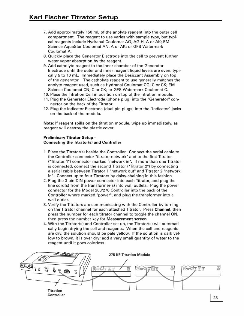
Preliminary Titrator Setup -
Connecting the Titrator(s) and Controller
1. Place the Titrator(s) beside the Controller. Connect the serial cable tothe Controller connector "titrator network" and to the first Titrator("Titrator 1") connector marked "network in". If more than one Titratoris connected, connect the second Titrator ("Titrator 2") by connectinga serial cable between Titrator 1 "network out" and Titrator 2 "networkin". Connect up to four Titrators by daisy-chaining in this fashion
2. Plug the 3-pin DIN power connector into each Titrator, and plug theline cord(s) from the transformer(s) into wall outlets. Plug the powerconnector for the Model 260/270 Controller into the back of theController where marked "power", and plug the transformer into awall outlet.
3. Verify the Titrators are communicating with the Controller by turningon the Titrator channel for each attached Titrator. Press Channel, thenpress the number for each titrator channel to toggle the channel ON,then press the number key for Measurement screen.
4. With the Titrator(s) and Controller set up, the Titrator(s) will automati-cally begin drying the cell and reagents. When the cell and reagentsare dry, the solution should be pale yellow. If the solution is dark yel-low to brown, it is over dry; add a very small quantity of water to thereagent until it goes colorless.
powernetwork
outgeneratorprobe
indicatorprobe
balancenetwork
in
powernetwork
outgeneratorprobe
indicatorprobe
balancenetwork
inpower
networkoutgenerator
probe
indicatorprobe
balancenetwork
in
ch. A
ref. A
ch.B
tempA
RS232Cpower
ch. FFET
tempB
ch. Cconductivity
ref
titratornetwork
275 KF Titration Module
Titration
Controller

24
Karl Fischer Titration Mode
Running a Titration
1. Select one or more titrator channels for active display bypressing Channel and pressing the number key for eachtitrator channel to toggle ON or OFF. When all channelshave been set, press the number key for Measurement
screen or press the Measure softkey (the softkey with themeter and needle symbol).
2. Press Mode and select one of the 10 stored KF titrationprotocols (protocols are methods) to use for the selectedTitrator. If multiple channels are active, Select the Titratorto change mode (protocol).
3. Modify the protocol if necessary by pressing Setup, 4)
Titration setup menu, 1) Modify titration protocol, andselect the protocol. Any changes made to this protocolare immediately stored for the protocol and are automati-cally sent to all Titrators using that specific protocol. TheTitrators using any given protocol are displayed at the topof the screen.
4. Press the Titration softkey to start the titration. If multipletitrators are turned on, select the titrator to start.
5. If micrograms or milligrams water are the units, the Addsample reminder and countdown will begin and the titra-tion start immediately. After adding the sample pressEnter.
If % or ppm water are the units, enter the weight for thesample and container (usually a syringe). Type in theweight value, or use automatic transfer from a balance,then press Enter. Common practice is to tare the balancewith the sample/syringe on it, and enter this weight aszero.
6. Immediately add the sample to the cell. The Controllerwill display "Add sample: 00:20" and countdown the pro-grammed sample introduction time. Be sure to beginadding the sample within this time period, or the Titratormay end the titration before the sample is added to thecell.
7. If % or ppm are the units, enter the empty containerweight. If the balance was tared with the syringe andsample, when the syringe is placed back on the balancethe weight is displayed as a negative value. Enter thisnegative value using the ± key. If weight transfer from abalance is set up, the weight appears in the display auto-matically, just press Enter.
8. The Controller returns to the main measure screen. Insingle channel display, a full screen real-time titrationcurve is displayed, showing the progress of the titration.In multiple channel mode there is no titration graph. Thestatus of the Titrator is displayed ("Titrating"), and whenthe titration is complete the status changes to "Done"briefly, then a "checkmark" appears by the titrator channelindicator to show the titration is done and the data isready. The status changes to "Ready to titrate", or theappropriate status.
Select Channel to Change Mode
1) Titrator 1: % Water
2) Titrator 2: % Water
3) Titrator 3: % Water
4) Titrator 4: % Water
5) Channel A: pH
6) Channel B: pH
7) Channel F: pH
8) Channel C: Conductivity
Titrator 1
Select New Protocol
1) % Water
2) ppm Water
3) Hydrocarbons
4) Solids
5) KF Oven
6) User6
7) User7
8) User8
9) User9
0) User10

25
Karl Fischer Titration Mode
Titrator Status and Operating Data
Press Cal Data, select the Titrator if displaying multiple chan-nels, to see that Titrator's current operating data, includingstatus, current result, background drift rate, and reagent con-dition.
Background drift rate is an important parameter to monitor. Itis also displayed for each titrator in the main measure screen.If the Titration Cell is sealed well to prevent ambient watervapor from entering the cell, and if there are no Karl Fischerreaction byproducts or sample components that are causingside reactions in the cell, then the background drift rateshould be a low number, typically less than 6 ug/min. Thebest results will be obtained when the background drift rate islow and stable. For maximum accuracy, the Titrator automat-ically subtracts the background drift from the titration resultthroughout the titration. Large drift rates may be reduced bychecking the desiccant, the cell seals and joints, cleaning thecell and replacing the reagents.
Reagent condition is indicated by the titration current, dis-played in milliamps (mA), and shown by the bar graph. Themarks on the bar graph indicate the full current obtained withfresh reagents of the AG/AN, A or AK types. As the reagentsbecome exhausted the current will decrease and titrations willtake longer. At 90 mA the error message "Reagents exhaust-ed" appears, and reagents must be changed.
Statistics on the previous titration results are available bypressing the X-bar softkey. The average, standard deviation,Relative Standard Deviation, minimum, maximum and count(the number of data points used) are displayed. The numberof values used, "N", can be set by pressing the N softkey.Many analysts use the average three KF titrations to increasetheir accuracy. Obtaining precise results, especially on awater standard, is a useful check on the analytical techniqueof the analyst. Good technique usually leads to repeatable,precise results with a low standard deviation.
Note: when using the average be sure to have the last "N"results for the selected Titrator are results from the samesample or standard. Example: if N is three, and only twotitrations have been run on a sample, then the third previousresult was from a different sample and the statistics will benot be correct!
Titrator 1 %Water
Titrator Data
Status: Titrating 15:58
Result: — — —
Drift: 0.0 µg/min
Reagent: 321 mA
Titrator 1
Titrator Statistics
Average: 1003.1
Std Dev: 3.3
RSD: 0.33%
Minimum: 999.7
Maximum: 1006.3
Count: N=3
1006.3
999.7
1003.2
Lo AK A AG

26
Karl Fischer Titration Mode
Titration Setup Menu
Press Setup, 4) Titration setup menu to access KF titrationprotocols, intermediate result printout, select balance type,and control the Titrator stirrers.
1. Modify titration protocol: use to modify the 10 stored KFtitration protocols.
2. Select/assign protocol: use to select a protocol for aTitrator.
3. Print a protocol: use to print hardcopy of a stored protocol.4. Set printouts on/off: use to turn on or off printing interme-
diate titration results out the serial port to a printer/comput-er. Useful for monitoring the rate of titrating water in asample when developing the optimal protocol for a specificsample.
5. Set printout interval: use to set the time interval in secondsfor printing intermediate titration results.
6. Select balance type: use to set the balance attached toTitrator 1 for automatic weight transfers. The output stringof the balance must match the type selected in order forthe Titrator to use the balance data.
7 -0. Turn stirrer 1 on/off: use to temporarily turn off a Titratorstirrer in order to replace the cell onto the Titrator andhave the stirbar magnetically couple. The Titrators aredesigned to maintain an equilibrium in the cell, and socontinuous stirring is required. All paused stirrers areautomatically turned back on when this Setup menu isexited.
Titration Setup Menu
1) Modify titration protocol2) Select/assign protocol3) Print a protocol4) Set printouts on/off :OFF5) Set printout interval: 6 sec6) Select balance type : A/M7) Turn stirrer 1 on/off :ON8) Turn stirrer 2 on/off :ON9) Turn stirrer 3 on/off :ON0) Turn stirrer 4 on/off :ON
NOTE: Any paused stirrers will automatically restartwhen you leave this screen.
Select Protocol to Modify
1) % Water
2) ppm Water
3) Hydrocarbons
4) Solids
5) KF Oven
6) User6
7) User7
8) User8
9) User9
0) User10
Select Titrator to Assign Protocol
1) Titrator 1: % Water
2) Titrator 2: % Water
3) Titrator 3: % Water
4) Titrator 4: Solids
Set Balance Type
1) Denver TL, TR or TC
2) Denver A or M
3) Denver DI
4) Denver AB
5) Denver AE

27
Cleaning the Titration Cell
General Cleaning
Large cell body - wash with a detergent solution, rinse with de-ionizedwater and rinse with methanol or acetone. Do not add reagents untilthe cell is dry. If drying in an oven, remove all plastic componentsincluding the stopcock.
KF electrode and stir bar - wipe with Chemwipe being careful not tobend Pt wires.
Cleaning the Generator Assembly
1. Block the hole in the upper glass portion of the Generator Assembly,this is where the platinum wire goes from the inside to the outside ofthe assembly. A recommended method is to wrap a piece ofParafilm around the Generator Assembly. When covering the holebe sure that the wrap is not long enough to reach the solvent levelas the vacuum created can pull liquid between the Parafilm and thegenerator and in through the wire hole.
2. Have a vacuum source available. One method is to use a vacuumaspirator.
3. Attach the aspirator to a faucet and connect the Generator Assemblyto the aspirator. (See Diagram)
4. Place the Generator Assembly into a beaker of the appropriate sol-vent that the samples analyzed are known to dissolve in. Typical sol-vents include hexane, methenol, acetone, chloroform and tolune.
5. Apply the vacuum and draw the solvent up through the frit.6. Repeat until the frit appears to be clean. This includes the removal
of any discoloration that may have accumulated from sample analy-sis. The solvent being drawn through should appear clear and clean,the absence of an oil layer in the solvent drawn through or any pre-cipitate on the frit, and are indications the frit is clean. The solvent isdrawn through the frit easier.
7. More than one reagent may be drawn through the frit for cleaningpurposes. (Typically concentrated nitric acid is used second).
8. The last solvent to be drawn through the generator assembly shouldbe either methanol or acetone.
9. Final cell drying should be done in an oven at 60°-75° C overnightand cooled in a dessicator.
Note:
Do not clean generator assembly with water
or solutions diluted with water.
Warning!
Do not heat the Generator Assembly above 80° C.
Damage will result.
Caution!
Let the cell cool before filling it with fresh Karl Fischer reagent,which
is mostly methanol and is flammable!
!
!

28
Cleaning the Titration Cell
10. Place fresh coulometric Karl Fischer reagents in the celland Generator Assembly, place the cell on the Titratorand begin the automatic cell and reagent dryingprocess. It may take a newly cleaned frit some time forreagent to diffuse into the frit and provide full titrationcurrent.
11. If the above procedure does not clean or unclog theglass frit, it may be necessary to use strong cleaningagents. For severely clogged frits, a chromic acid orconcentrated nitric acid cleaning process is recom-mended.
Caution!
These are strong acids and must be used with appropriate
care and protection!
Reagent Selection
Coulometric Karl Fischer reagents are available from sever-al manufacturers, including Riedel-de Haen Hydranal, EMScience AquaStar and GFS Watermark. The reagent ischosen so that its polarity will dissolve the samples. Themost common reagent type is the "AG" or "AN" methanolbased, next is the non-polar chloroform or long-chain alco-hol based "A", "AG-H" types for oils and other hydrocar-bons, and samples with ketones or aldehydes must be runin the special ketone reagents "AK". Contact DenverInstrument Electrochemistry Technical Support, or the vari-ous reagent manufacturer's Technical Support for addition-al assistance.
Balance interface
Weight based measurements are the most accurate, andusing a three or preferably four place balance is recom-mended. Automatic weight transfer from the balance tothe Titrator is a fast, error-free way to enter weights. TheTitrator supports most Denver Instrument balances. Thebalance is attached to the balance port on Titrator 1, andserves for all Titrators. The balance type must be set inthe Controller, and the balance must be set to 4800 baud,parity off, continuous once per second output. For exactsettings for each Denver Instrument balance, contactTechnical Support at 800-321-1135.
!
Cover the holeusing parafilm
Connect towater faucet
29
Troubleshooting Karl Fischer Titration
Common Errors and Solutions
Indicator error
• Check the KF electrode (dual platinum) to see if it is plugged in.• Check that the platinum tips are not touching each other or the cell.• Check for crack(s) in the electrode.• Verify that the reagents are not over dry (dark in color).• Clean the platinum tips thoroughly.
Generator error
• Check the Generator Assembly to see if it is plugged in at both ends.• Check the platinum grid at the bottom of the Generator Electrode.
Drying reagents
• If there are bubbles rising in the Generator Electrode, it is drying. Thereis water trapped in the cell and it must be titrated before continuing.
• Add a small amount of Composite 5 reagent to the cell to help dry thecell more quickly.
• If it is not bubbling and the reagents are getting darker, unplug the mod-ule and controller and replug back in while adding a drop of water.
• If reagents smell like sulfur, dispose of them. The cell then needs to becleaned and dried in an oven (See Cleaning Instruction).
Over dry
• Add a drop of water.• Keep adding a drop at a time until the solution goes clear and Controller
displays “Ready to titrate” or “Drying reagents”.Titrators off-line
• Reconnect all serial cable connections.• Verify serial cables go to correct connections (“in” and “out”). Press the
Titration softkey, then select 6) reinitialize network’.• Unplug power to the Titrators and Controller and replug them back in.
Stir bar not spinning
• Check to see that the module is plugged in.• For further information contact Technical Assistance, a replacement
motor kit may be necessary.Low Results
• Verify after injecting the sample, no sample is left on the end of the nee-dle prior to pulling it out.
• Change the desiccant and cotton, also inspect the septum and replace asnecessary.
• Verify that the drift rate is normal (not high).• Calibrate balance.• Clean the cell and frit.• Replace reagents.
High results
• Verify that when injecting, that all of the sample was injected into thereagents and not on the side of the reaction cell.
• Verify that the drift rate is normal• Check all seals on the reaction cell, and secure as needed.• Calibrate the balance.• Clean the cell and frit.• Replace reagents.

30
Modifying Titration Protocols
Each Titrator runs one of the 10 stored protocols. The pro-tocol controls all parameters of the titration, including theunits, sample introduction time, sample extraction time,endpoint persistence time, endpoint slope, and a solventblank.
Stored protocols include typical titration protocols formeasuring water content in easily analyzed liquid samplesin % and ppm units, for measuring water in hydrocarbons,water in slower to release solids, and water in plasticsbeing introduced by a KF oven/vaporizer. These protocolscan be modified and renamed, and five additional proto-cols are available for users.
A generic protocol often provides good results, but occa-sionally must be modified for a specific sample. Examplesof modifications include changing the time for a titration,either as additional "up-front" time with introduction time,or as additional post-endpoint time with persistence time,or using a low endpoint slope value like 0.05 to force atitration to continue longer.
1. Each protocol has a user-entered name.2. Units of micrograms, milligrams, %, ppm, or mg/l can
be selected. % and ppm are weight:weight water:sam-ple. The mg/l unit is weight:volume.
3. Sample introduction time should provide ample time toget the sample into the cell. Sometimes a little extratime is helpful, and can be set.
4. Extraction time allows time for a slow dissolving, slowwater releasing, or slow mixing sample to release waterto the reagent system for titration.
5. Endpoint persistence time is additional time after firstreaching the endpoint that the titrator continues totitrate; use to ensure complete recovery of water fromdifficult samples.
6. Endpoint slope is the primary endpoint control. Thetitrator will titrate until the set slope (rate of waterrecovery from the sample in micrograms water/second)is reached; use to ensure complete recovery of waterfrom slowly releasing samples such as solids or crys-talline materials. This has little effect on miscible liquidsamples which usually release water quickly.
7. Use a solvent blank to subtract water present in a sol-vent used to dissolve otherwise insoluble solid samples.The sample is dissolved in a fixed volume of a solvent,then that solvent is injected into the cell. Determine thewater content of the fixed volume of solvent in micro-grams, then set that value as a blank to be subtracted.
Titrator 1
Modify Titration Protocol
1) Change name% Water
2) Select units% H20
3) Set introduction time00:20 min:sec
4) Set extraction time00:00 min:sec
5) Set persistence time00:15 min:sec
6) Set endpoint slope0.05 µg/s
7) Set solvent blank0.0 µg H2O
Set Protocol Units
1) µg H2O
2) mg H2O
3) % H2O
4) ppm H2O
5) mg/l H2O
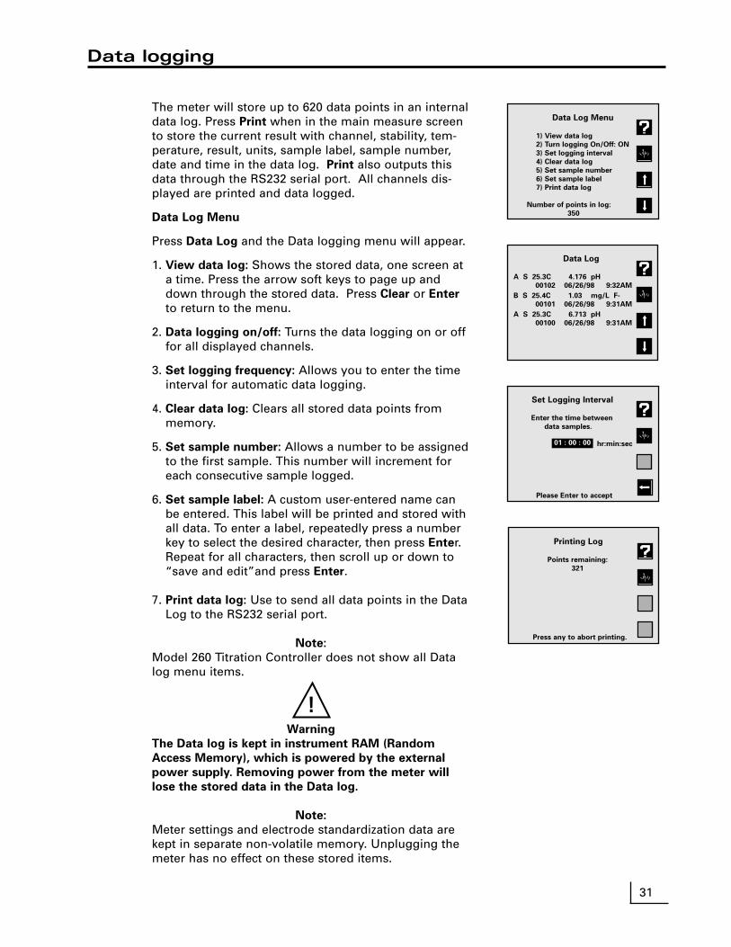
The meter will store up to 620 data points in an internaldata log. Press Print when in the main measure screento store the current result with channel, stability, tem-perature, result, units, sample label, sample number,date and time in the data log. Print also outputs thisdata through the RS232 serial port. All channels dis-played are printed and data logged.
Data Log Menu
Press Data Log and the Data logging menu will appear.
1. View data log: Shows the stored data, one screen ata time. Press the arrow soft keys to page up anddown through the stored data. Press Clear or Enter
to return to the menu.
2. Data logging on/off: Turns the data logging on or offfor all displayed channels.
3. Set logging frequency: Allows you to enter the timeinterval for automatic data logging.
4. Clear data log: Clears all stored data points frommemory.
5. Set sample number: Allows a number to be assignedto the first sample. This number will increment foreach consecutive sample logged.
6. Set sample label: A custom user-entered name canbe entered. This label will be printed and stored withall data. To enter a label, repeatedly press a numberkey to select the desired character, then press Enter.Repeat for all characters, then scroll up or down to“save and edit”and press Enter.
7. Print data log: Use to send all data points in the DataLog to the RS232 serial port.
Note:
Model 260 Titration Controller does not show all Datalog menu items.
Warning
The Data log is kept in instrument RAM (Random
Access Memory), which is powered by the external
power supply. Removing power from the meter will
lose the stored data in the Data log.
Note:
Meter settings and electrode standardization data arekept in separate non-volatile memory. Unplugging themeter has no effect on these stored items.
Data logging
!
Data Log Menu
1) View data log
2) Turn logging On/Off: ON
3) Set logging interval
4) Clear data log
5) Set sample number
6) Set sample label
7) Print data log
Number of points in log:
350
Data Log
A S 25.3C 4.176 pH
00102 06/26/98 9:32AM
B S 25.4C 1.03 mg/L F-
00101 06/26/98 9:31AM
A S 25.3C 6.713 pH
00100 06/26/98 9:31AM
31
Set Logging Interval
Enter the time between
data samples.
hr:min:sec
Please Enter to accept
01 : 00 : 00
Printing Log
Points remaining:
321
Press any to abort printing.

32
Testing the Electrode and Meter
To test the meter for correct operation without a pH, ORP orIon Selective electrode, short the BNC input connector (eitherChannel A or B) using the BNC Shorting Cap that was suppliedwith the meter on the BNC connector(s). Select the correctchannel using Channel. Select mV mode by pressing Mode
and selecting 2) mV. Verify meter is in absolute mV mode (dis-play shows “mV”, not “rel mV”). If the meter reads 0 ± 0.1mV*, and is stable, the meter is measuring correctly.
To test the pH electrode, place it in a fresh pH 7 buffer. Selectthe correct channel for the electrode using Channel. PressMode and select 2) mV. Verify that the meter is in absolute mVmode (display shows "mV", not "rel mV") and note the mVreading. Repeat for either a pH 4 or pH 10 buffer. If the elec-trode potential is within the limits shown, it is measuring cor-rectly.
pH 7 0 ± 30 mVpH 4 159 to 186 mV higher than pH 7 readingpH 10 159 to 186 mV lower than pH 7 reading
* Note: Meter accuracy is ±0.1 mV at calibration temperature,not including long term drift and any temperature error. Thezero and slope temperature coefficients of the meter over therange of 15 to 40°C specify 85ppm/°C, or ±4 mV at full scale(worst case). The long term drift should not exceed 0.1 mV permonth. This results in an expected range of 0 ± 0.3 mV with 1minute stability of ± 0.1 mV at room temperature.
Troubleshooting

33
pH
0 Strong Acid
1
2 Lemon Juice
3
4 Tomato Juice
5 Coffee
6
Neutral 7 Pure water
8 Baking Soda
9
10
11
12 Ammonia
13
14 Strong Base
Mo
re A
cid
icM
ore
Basic
pH scale showing therelative acidity or basicity ofsome common substances
pH Theory
The measurement of pH plays an important role in water quali-ty, industry and research. pH is a measure of acidity or alkalinityof a solution, and is usually written:
pH = -log [H+]
Where [H+] is the concentration of hydrogen ions.
pH levels generally range from 0 to 14, with a pH value of 7being the neutral point. pH values greater than 7 are alkaline,and pH values less than 7 indicate acidic solutions.
Conventional pH meters use a combination glass pH electrode,which includes a reference electrode. The reference electrodeprovides a stable reference point and completes the electricalcircuit. The pH meter reads the voltage of the two electrodes,converts it to pH units, and displays the result.
These meters can also use a Field Effect Transistor (FET)pH/ATC electrode for measuring pH. The FET uses an ion-sens-ing solid state membrane attached to a transistor to measurethe hydrogen ion concentration of a solution. These non-glasspH electrodes offer durability, dry storage and no glass con-struction.
The electrode signal varies with the pH, according to the NernstEquation:
E = E° + S • log [H+]
Where:
E = measured electrode potentialE° = standard potential of the system (constant)S = slope

34
Understanding Conductivity Temperature Correction
Conductivity measurements are dependent upon temperature.It has been determined that for most standard solutions thereis a 1.9% change per degree Celsius.
Traditionally conductivity measurements are reported at 25°C.The 200 series factory default is to correct all conductivity val-ues to 25°C using the 1.9%/°C value. However you can definethe correction temperature and value in the conductivityoptions menu. To turn temperature correction “off” select 0%.
When entering in conductivity standardization values, it is nec-essary to enter the value of the standard at the current tem-perature. To calculate this value:
1. Subtract the current temperature of your standard from 25°(the temperature at which the value of the standard was cal-culated).
2. Multiply this number by 1.9% which is your default temper-ature coefficient.
3. Multiply this number by the value of the standard (from thebottle).
4. Now subtract this number from the value of your standard(from the bottle). This is the value you enter into the instru-ment for the standard.
For example, if the standard solution is 1035 µS and the cur-rent temperature is 23.4°:1. 25.0 - 23.4 = 1.62. 1.6* 0.019 = 0.03043. 0.0304* 1035 = 31.464. 1035 - 31 = 1004 µS
Type the value of 1004 µS into the meter and the meter willtemperature correct to make the reading on the display 1035µS, which is the true value of the standard.

Understanding pH Temperature Compensation
NOTE: Temperature compensation only takes
effect when an ATC probe is attached.
There are two ways that temperature compensa-tion affects pH measurement:
1. Buffer pH values change with temperature.
Each buffer changes depending on the tempera-ture of the solution. These values are typicallyfound on the label of the buffer. The table atright is representative of most buffers.
When standardization is performed in pH mode,the pH value is adjusted to the current value forthe current temperature.
For example, if your pH 7 buffer is at 20°C themeter will standardize your buffer at 7.02 insteadof 7.00 which is the value at 25°C.
2. The electrode efficiency changes with temper-
ature.
The standard mV change per pH unit is approxi-mately 59.17 at 25°C. However, as shown in thegraph at right, this mV per pH unit valuechanges as temperature changes.
The meter compensates for this change bychanging the pH reading as temperaturechanges.
U.S. Standard BufferpH 4.00 pH 7.00 pH 10.00
0°C 4.005 7.13 10.345° 4.003 7.10 10.2610° 4.001 7.07 10.1915° 4.002 7.05 10.1220° 4.003 7.02 10.0625° 4.008 7.00 10.0030° 4.010 6.99 9.9435° 4.020 6.98 9.9040° 4.03 6.97 9.8550° 4.061 6.97 9.78
isopotentialpoint
electrodepotential(mV)
500
-500
0
0 7 14
100°C (74mV/pH unit)
50°C (64mV/pH unit)
0°C (54mV/pH unit)
Typical pH electrode response as afunction of temperature
Ion Selective Electrode Theory
The measurement of ions plays an important rolein water quality, industry, research and environ-mental monitoring. Ion-selective Electrodes(ISE’s) respond, more or less exclusively, to aspecific type of ion in solution. The particular ionto which an ISE responds depends on the chemi-cal makeup of its sensing membrane. ISE’s oper-ate according to a form of the Nernst equation:
E = Eo + S • log [ion]
35

36
The Isopotential point is the potential of an electrode system which does not change withtemperature. Typical pH electrodes have isopotential points near zero mV (which is thedefault setting for the meter). For high accuracy pH measurements, or for ion measure-ments where the sample temperature may widely vary, the isopotential of the pH or ionelectrode may be experimentally determined and entered into the meter.
• Prepare a set of buffers or ion standards spanning the linear range of the electrode.Place the buffers or standards in a temperature bath at known temperature.
• Place the meter into mV mode.
• Measure and record mV readings of each pH or concentration, and repeat at severaltemperatures.
• Plot the log of concentration or pH value versus mV reading.
• Connect the points for each temperature.
Where the lines intersect is the Isopotential point.
Determining the Isopotential Point
200
100
010-3 10-4
Log of Ion Concentration, moles/L
Electrode
Output
(mV)
10°C
60°C
Isopotential Point:
3.07 x 10⁻⁴ moles/L, 162 mV
Ion Electrode Isopotential Point
50
150
-180
0
1804 7 10
pH
Electrode
Output
(mV)
25°C
10°C
Isopotential
Point: 7.04pH 9
pH Electrode Isopotential Point

The Denver Instrument Series 200 meters have a bi-directional RS-232 serialport, which can be used to send commands to the meter and output data fromthe meter. Special characters (Ω, µ, é) are coded using ASCII (not ANSI); usean ASCII font like “Terminal”. Also use a terminal emulation like TTY or ANSI,not VT100.Serial commands follow either "keystroke" mode or high level command modeconsisting of "SET", "GET" and "DO" instructions. (Note: “GET” and “DO” are optional).
Keystroke instructions
KEYS M ModeZ StandardizeC Cal DataH ChannelS SetupL Data LogR ClearN Enter/Print[0 to 9] Equivalent to pressing a numeric key- +/- key. Decimal keyE Used within a number to enter values in exponential form! Press softkey #1 (at top, usually Help)@ Press softkey #2 (usually return to measuring screen)# Press softkey #3 (usually up arrow)$ Press softkey #4 (at bottom, usually down arrow)
Notes: Key commands are acknowledged by the meter with a reply Keys = COMMAND_RECEIVED. Multiple keys can be concatenatedtogether into a single command, for example, Keys Z413@(Standardize, options, resolution, set to 3, main), or Keys Z4721.2-N@(Set manual temperature to -1.2).
High level instructions
Use commands SET, GET, DO.Follow command by a keyword like MODE, STDZPH, STDZCONDO, CALDATA, STDZCLEAR, CHANNEL, DATETIME, TIMESTAMP, DISPLAY, READ,INFOTypical Syntax: [command] [keyword] [channel] [variable(s)]
Error conditions are replied to with an Error response; for example:"Error: Need channel", "Error: Need mode", "Error: Unspecified"
Accepted commands have a response; indicated below for each command.
Mode operations
set mode "channel character" "mode id"
Examples: SET MODE A PH SET MODE B MVSET MODE B IONSET MODE C CONDUCTIVITY
Returns confirmation; for example "SET MODE A PH" returns "A mode = PH".Valid modes are (depending on the meter model) PH, MV, CONDUCTIVITY,RESISTIVITY, PRAC_SALINITY, NACL_SALINITY, DISSOLVED_SOLIDS.
RS-232 Serial Interface Meter Command Set
37
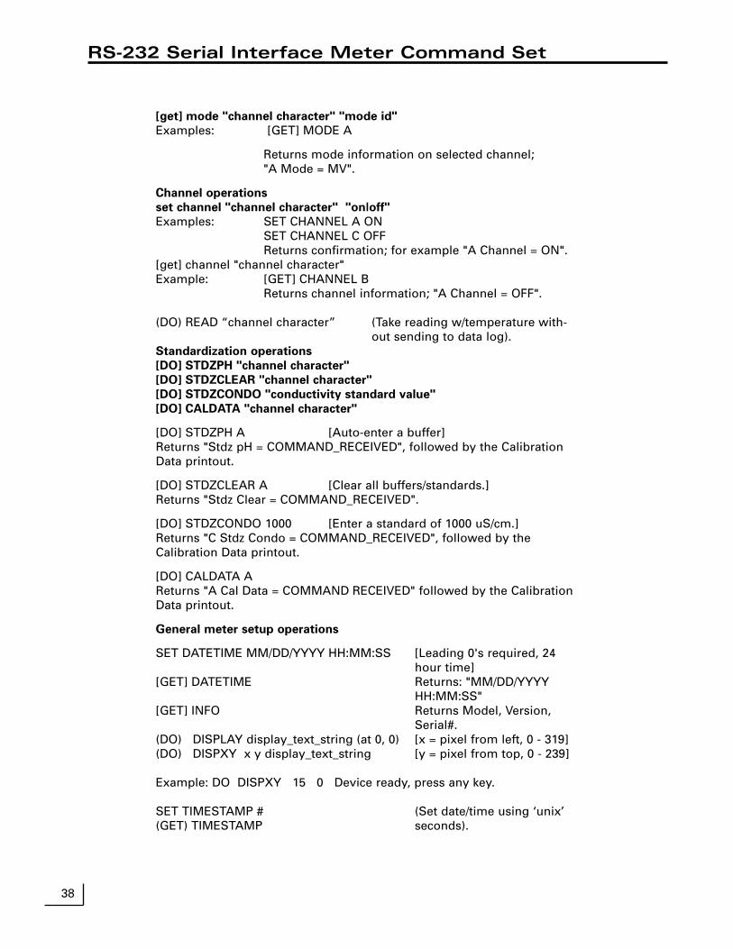
38
RS-232 Serial Interface Meter Command Set
[get] mode "channel character" "mode id"
Examples: [GET] MODE A
Returns mode information on selected channel; "A Mode = MV".
Channel operations
set channel "channel character" "on|off"
Examples: SET CHANNEL A ONSET CHANNEL C OFFReturns confirmation; for example "A Channel = ON".
[get] channel "channel character"Example: [GET] CHANNEL B
Returns channel information; "A Channel = OFF".
(DO) READ “channel character” (Take reading w/temperature with-out sending to data log).
Standardization operations
[DO] STDZPH "channel character"
[DO] STDZCLEAR "channel character"
[DO] STDZCONDO "conductivity standard value"
[DO] CALDATA "channel character"
[DO] STDZPH A [Auto-enter a buffer]Returns "Stdz pH = COMMAND_RECEIVED", followed by the CalibrationData printout.
[DO] STDZCLEAR A [Clear all buffers/standards.]Returns "Stdz Clear = COMMAND_RECEIVED".
[DO] STDZCONDO 1000 [Enter a standard of 1000 uS/cm.]Returns "C Stdz Condo = COMMAND_RECEIVED", followed by theCalibration Data printout.
[DO] CALDATA AReturns "A Cal Data = COMMAND RECEIVED" followed by the CalibrationData printout.
General meter setup operations
SET DATETIME MM/DD/YYYY HH:MM:SS [Leading 0's required, 24hour time]
[GET] DATETIME Returns: "MM/DD/YYYYHH:MM:SS"
[GET] INFO Returns Model, Version,Serial#.
(DO) DISPLAY display_text_string (at 0, 0) [x = pixel from left, 0 - 319](DO) DISPXY x y display_text_string [y = pixel from top, 0 - 239]
Example: DO DISPXY 15 0 Device ready, press any key.
SET TIMESTAMP # (Set date/time using ‘unix’ (GET) TIMESTAMP seconds).
Maintenance
This product contains no user serviceable parts. All replacementparts should be obtained from the manufacturer or an authorizeddistributor.
Cleaning
The exterior surfaces of this product may be cleaned with a dampcloth or with mild detergent.
Caution
Changes or modifications not expressly approved by the manufac-turer will void the user’s warranty for this equipment.
!
39

Menu Tree Diagram
1) pH2) mV3) Ion
1) Auto-enter a buffer2) Manual buffer entry3) Clear buffers4) Options menu5) Cal reminder menu6) Select buffer set
1) Select resolution2) Select stability criteria3) Select signal averaging4) Set standardization delay5) Set pH slope6) Standardize menu7) Manual temperature menu8) Data alarm menu9) Set isopotential point
1) Auto-enter mV offset2) Set mV offset3) Clear mV offset4) Options menu
1) Select resolution2) Select stability criteria3) Select signal averaging4) Set standardization delay5) Set mV offset6) Standardize menu
1) Enter a standard2) Set ion slope3) Clear standards4) Options menu5) Cal reminder menu
1) Select resolution2) Select stability criteria3) Select signal averaging4) Set standardization delay5) Set ion slope6) Standardize menu7) Manual temperature menu8) Data alarm menu9) Set isopotential point0) Enable incremental modes
1) Conductivity2) Practical salinity3) NaCl salinity4) Resistivity5) Total dissolved solids
1) Enter a standard2) Set cell constant3) Clear standards4) Options menu5) Cal reminder menu6) Calculate solids factor
(TDS mode only)7) Set solids factor
(TDS mode only)
1) Select resolution2) Select stability criteria3) Select signal averaging4) Set standardization delay5) Set cell constant6) Standardize menu7) Manual temperature menu8) Data alarm menu9) Set temperature coeff.
1) Time and date menu2) Select temperature units3) Select contrast4) Select baud rate
[Model 215 - 250]Titration setup menu [Model 260 - 270]
5) Setup serial port [Model 215 - 250]Serial port menu [Model 260 - 270]
6) Keypress beep on/off7) Select video color scheme8) Show meter information9) Enable measure lock0) Enable strict calibration±) Set screen saver timeout.) Restore factory defaults
1) View data log2) Turn logging On/Off :OFF3) Set logging interval4) Clear data log5) Set sample number6) Set sample label7) Print data log
Mode (A, B & F)
pH Standardize Menu:
pH Options Menu:
mV Standardize Menu:
mV Options Menu:
Ion Standardization Menu:
Ion Options Menu:
Conductivity Options Menu:
Setup Menu:
Data Log Menu:
Mode (C)
Conductivity Standardize Menu:
40

This manual covers Software Version 3.0
Manual and User Interface© Copyright Denver Instrument Company, 1999All rights reserved.
Warranty Instructions
1. Please return the prepaid, pre-addressed Purchase Registration Card to Denver InstrumentCompany promptly upon your purchase of the Denver Instrument product. The return of the cardis not a condition precedent to warranty coverage.
2. If you have any questions about a Denver Instrument product, please contact the nearest DenverInstrument office as listed below.
3. If it becomes necessary to return your Denver Instrument product for service, you must obtain a“Return Authorization Number”. Please pack the product securely in its original approved packingcarton or an other suitable container. Include your Return Authorization Number on the shippinglabel. Shipping charges must be fully prepaid.
Return to authorized distributor or :
North and South America: Denver Instrument Company
6542 Fig Street
Arvada, Colorado 80004
1-800-321-1135
Tel: 303-431-7255
Fax: 303-423-4831
U.K. and Ireland: Denver Instrument Company
Denver House, Sovereign Way
Trafalgar Business Park
Downham Market
Norfolk PE38 9SW England
Tel: 44 136 63862 42
Fax: 44 136 63862 04
Europe, Asia and Australia: Denver Instrument GmbH
Robert-Bosch-Briete 10
37079 Gottingen Germany
Tel: 49 551 20977 31
Fax: 49 551 20977 39
www.denverinstrument.com