200) bottom ported 3-way flanged ball valves...
TRANSCRIPT
2” – 8” (DN 50 – 200) BOTTOM PORTED 3-WAY FLANGED BALL VALVES
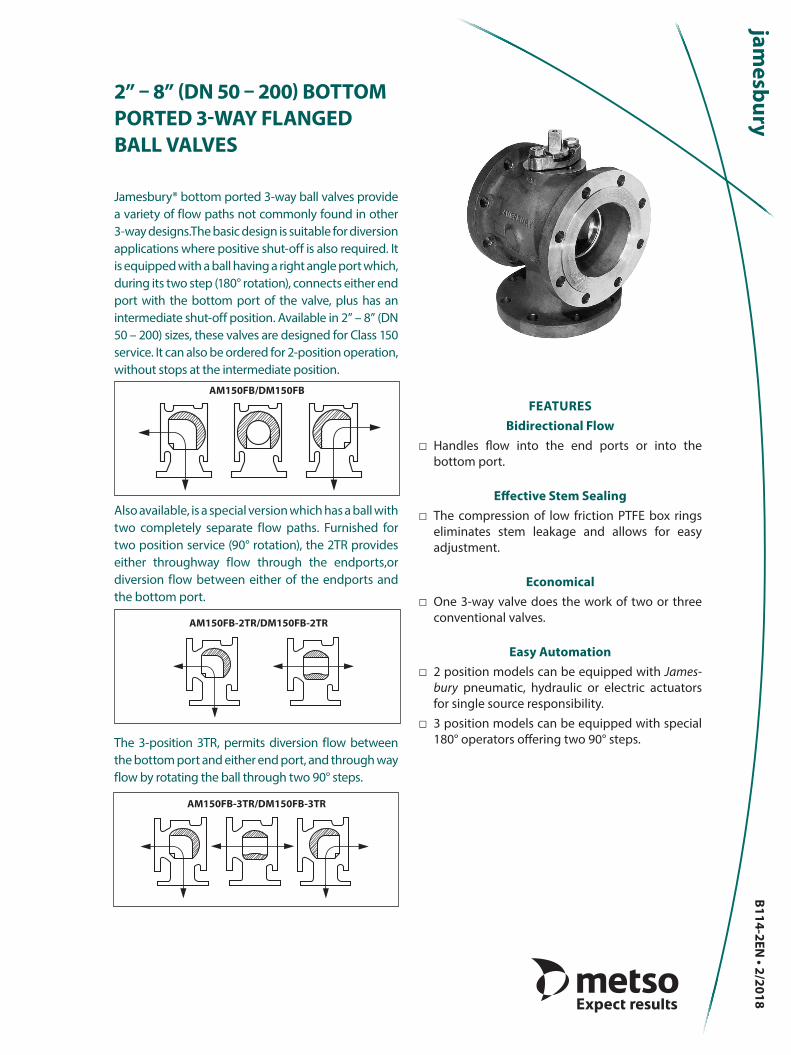
Jamesbury® bottom ported 3-way ball valves provide a variety of flow paths not commonly found in other 3-way designs.The basic design is suitable for diversion applications where positive shut-off is also required. It is equipped with a ball having a right angle port which, during its two step (180° rotation), connects either end port with the bottom port of the valve, plus has an intermediate shut-off position. Available in 2” – 8” (DN 50 – 200) sizes, these valves are designed for Class 150 service. It can also be ordered for 2-position operation, without stops at the intermediate position.
Also available, is a special version which has a ball with two completely separate flow paths. Furnished for two position service (90° rotation), the 2TR provides either throughway flow through the endports,or diversion flow between either of the endports and the bottom port.
The 3-position 3TR, permits diversion flow between the bottom port and either end port, and through way flow by rotating the ball through two 90° steps.
FEATURESBidirectional Flow
□ Handles flow into the end ports or into the bottom port.
Effective Stem Sealing □ The compression of low friction PTFE box rings
eliminates stem leakage and allows for easy adjustment.
Economical □ One 3-way valve does the work of two or three
conventional valves.
Easy Automation □ 2 position models can be equipped with James-
bury pneumatic, hydraulic or electric actuators for single source responsibility.
□ 3 position models can be equipped with special 180° operators offering two 90° steps.
AM150FB-3TR/DM150FB-3TR
AM150FB/DM150FB
AM150FB-2TR/DM150FB-2TR
B114-2EN • 2/2018
SPECIFICATIONS
VALVE SEAT RATINGS
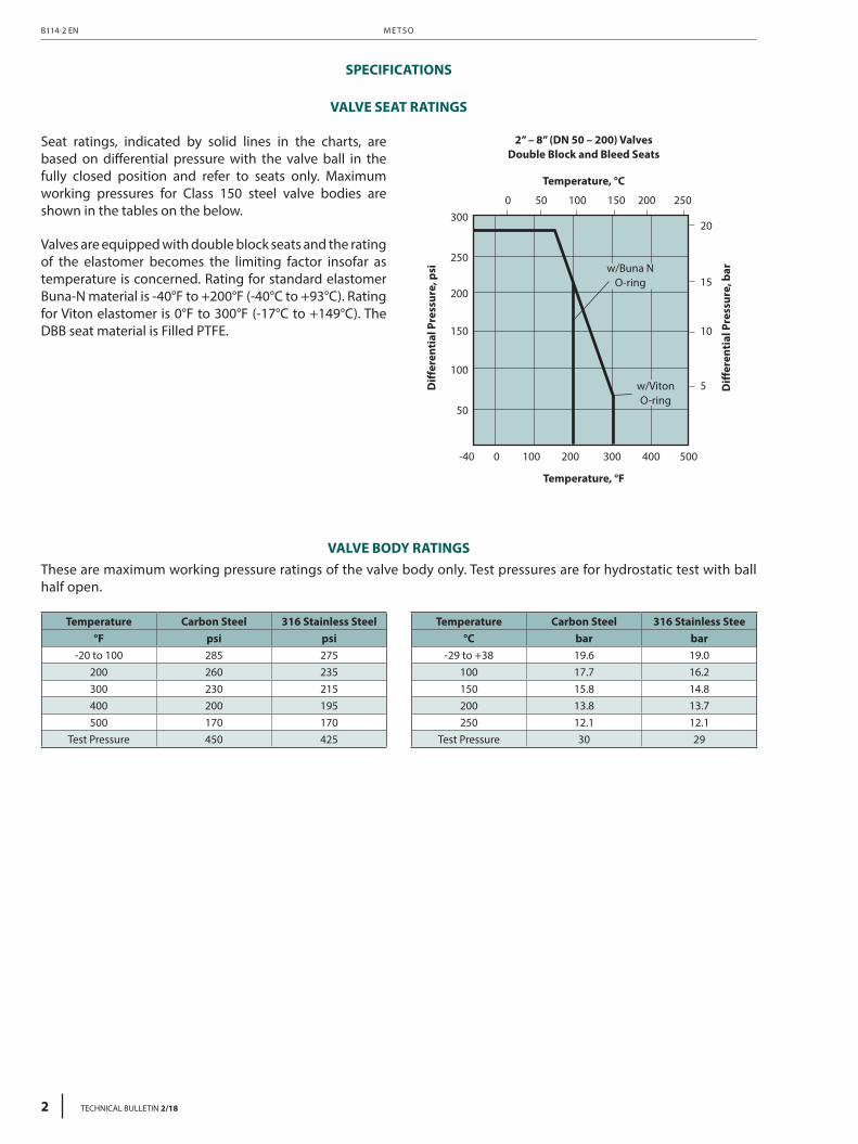
Seat ratings, indicated by solid lines in the charts, are based on differential pressure with the valve ball in the fully closed position and refer to seats only. Maximum working pressures for Class 150 steel valve bodies are shown in the tables on the below.
Valves are equipped with double block seats and the rating of the elastomer becomes the limiting factor insofar as temperature is concerned. Rating for standard elastomer Buna-N material is -40°F to +200°F (-40°C to +93°C). Rating for Viton elastomer is 0°F to 300°F (-17°C to +149°C). The DBB seat material is Filled PTFE.
2” – 8” (DN 50 – 200) ValvesDouble Block and Bleed Seats
Temperature, °C
0 50 100 150 200 250
-40 0 100 200 300 400 500
20
15
10
5
300
250
200
150
100
50
Diff
eren
tial
Pre
ssur
e, p
si
Diff
eren
tial
Pre
ssur
e, b
ar
Temperature, °F
w/Buna NO-ring
w/VitonO-ring
VALVE BODY RATINGSThese are maximum working pressure ratings of the valve body only. Test pressures are for hydrostatic test with ball half open.
Temperature Carbon Steel 316 Stainless Steel°F psi psi
-20 to 100 285 275200 260 235300 230 215400 200 195500 170 170
Test Pressure 450 425
Temperature Carbon Steel 316 Stainless Stee°C bar bar
-29 to +38 19.6 19.0100 17.7 16.2150 15.8 14.8200 13.8 13.7250 12.1 12.1
Test Pressure 30 29
M E T S OB114-2 EN
2 TECHNICAL BULLETIN 2/18
2” – 8” ( D N 50 – 200 ) B OT TO M P O R T E D 3 - WAY F L A N G E D B A L L VA LV E S B114-2 EN
TECHNICAL BULLETIN 2/18 3
FLOW DATA
AM150FB/DM150FBAM150FB-2TR-3TR/DM150FB-2TR-3TR
Valve Size
Cv Cv
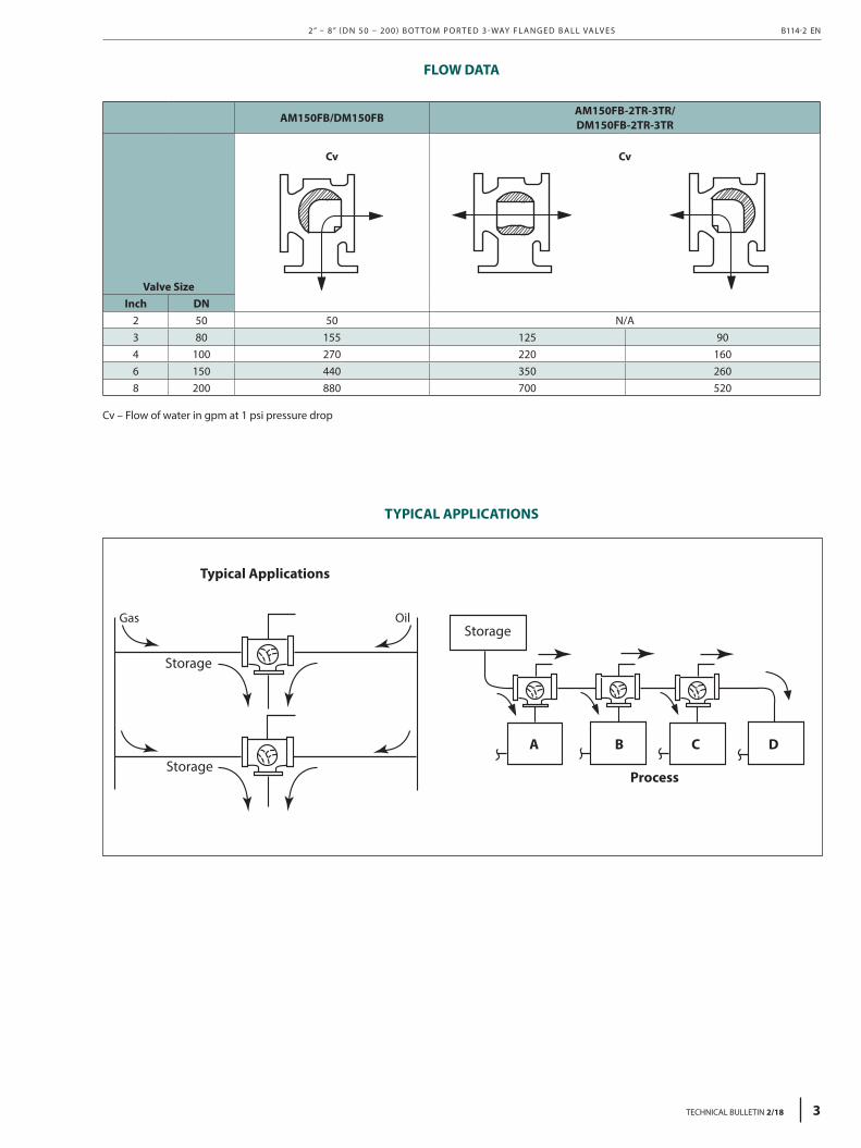
Inch DN2 50 50 N/A3 80 155 125 904 100 270 220 1606 150 440 350 2608 200 880 700 520
Cv – Flow of water in gpm at 1 psi pressure drop
TYPICAL APPLICATIONS
A B C D
Process
Storage
Storage
Storage
Typical Applications
Gas Oil
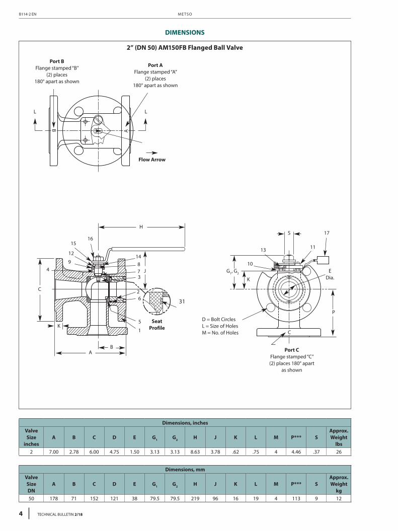
2” (DN 50) AM150FB Flanged Ball Valve
Port BFlange stamped “B”
(2) places180° apart as shown
Port AFlange stamped “A”
(2) places180° apart as shown
L L
A
Flow Arrow
HS
P
EDia.
C
K
G1, G2J
BA
K
C
SeatProfile
D = Bolt CirclesL = Size of HolesM = No. of Holes
Port CFlange stamped “C”(2) places 180° apart
as shown
B
1615
12
94
1
5
62
37
1413 11
17
108
31
Dimensions, inchesValve Size
inchesA B C D E G1 G2 H J K L M P*** S
Approx. Weight
lbs2 7.00 2.78 6.00 4.75 1.50 3.13 3.13 8.63 3.78 .62 .75 4 4.46 .37 26
Dimensions, mmValve Size DN
A B C D E G1 G2 H J K L M P*** SApprox. Weight
kg50 178 71 152 121 38 79.5 79.5 219 96 16 19 4 113 9 12
M E T S OB114-2 EN
4 TECHNICAL BULLETIN 2/18
DIMENSIONS
2” (DN 50) AM150FB – BILLS OF MATERIALS AND PARTS LIST
Part No. Part NameBody Material
Carbon steel (22) 316 Stainless steel (36)
1 Body Carbon steel ASTM A216 Type WCB 316 Stainless steel ASTM A351 Type CF8M
2 Insert Carbon steel 316 Stainless steel
3 Ball 316 Stainless steel
4 Stem 316 Stainless steel
5 Seat Elastomer backed filled PTFE
6 Body Seal PTFE
7 Stem Seal PTFE
8 Stem Bearing Filled PTFE
9 Compression Plate Carbon steel Stainless steel
10 Hex Jam Nut Carbon steel
11 Bonnet Screw 300 Series Stainless steel
12 Indicator Stop Carbon steel Stainless steel
13 Flat Head Cap Screw Stainless steel
14 Retaining Ring Carbon steel
15 Handle Carbon steel
16 Stem Nut 300 Series Stainless steel
17 Identification Tag 300 Series Stainless steel
31 O-Ring Buna-N or Viton A (as specified)
2” – 8” ( D N 50 – 200 ) B OT TO M P O R T E D 3 - WAY F L A N G E D B A L L VA LV E S B114-2 EN
TECHNICAL BULLETIN 2/18 5
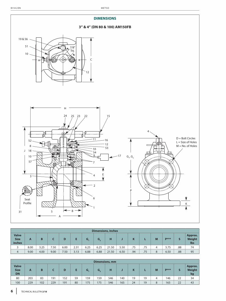
3” & 4” (DN 80 & 100) AM150FB
A
19 & 56
51
10
12
C
H
J
E
P
K
31 51
6
2
4
4
7
95455 53
17 G1, G2
121611
1522232524
52
8
18
10
57
3
B
SeatProfile
7/8”Sq.
AB
D = Bolt CirclesL = Size of HolesM = No. of Holes
Dimensions, inchesValve Size
inchesA B C D E G1 G2 H J K L M P*** S
Approx. Weight
lbs3 8.00 3.25 7.50 6.00 2.31 6.25 6.25 21.50 5.50 .75 .75 4 5.75 .88 744 9.00 4.00 9.00 7.50 3.13 6.88 6.88 21.50 6.50 .94 .75 8 6.50 .88 95
Dimensions, mmValve Size DN
A B C D E G1 G2 H J K L M P*** SApprox. Weight
kg80 203 83 191 152 59 159 159 546 140 19 19 4 146 22 34
100 229 102 229 191 80 175 175 546 165 24 19 8 165 22 43
DIMENSIONS
M E T S OB114-2 EN
6 TECHNICAL BULLETIN 2/18
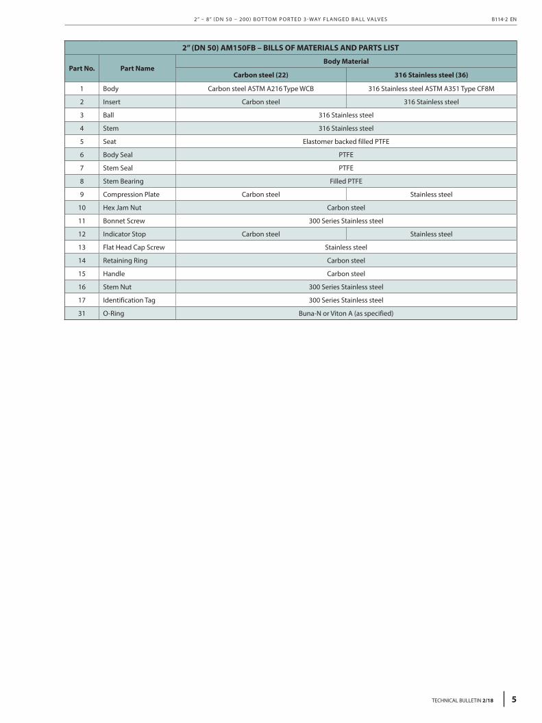
3” & 4” (DN 80 & 100) AM150FB – BILLS OF MATERIALS AND PARTS LIST
Part No. Part NameBody Material
Carbon steel (22) 316 Stainless steel (36)
1 Body Carbon steel ASTM A216 Type WCB 316 Stainless steel ASTM A351 Type CF8M
2 Insert Carbon steel ASTM A216 Type WCB 316 Stainless steel ASTM A351 Type CF8M
3 Ball 316 Stainless steel
4 Stem 316 Stainless steel
5 Seat Elastomer backed filled PTFE
6 Body Seal PTFE
7 Stem Seal PTFE
8 Stem Bearing Filled PTFE
9 Compression Plate Carbon steel Stainless steel
10 Hex Jam Nut Carbon steel
11 Bonnet Stud 300 Series Stainless steel
12 Indicator Stop Carbon steel Stainless steel
15 Handle Carbon steel
16 Stop Nut 300 Series Stainless steel
17 Identification Tag 300 Series Stainless steel
18 Compression Ring 300 Series Stainless steel
19 Lockwasher 300 Series Stainless steel
22 “T” Handle Adaptor Malleable Iron
23 Set Screw 300 Series Stainless steel
24 Stem Screw Carbon steel
25 Washer Carbon steel
31 O-Ring Buna-N or Viton A (as specified)
51 Bracket Carbon steel
52 Spring Plunger Carbon steel
53 Top Spacer Carbon steel
54 Lower Spacer Carbon steel
55 Stud Spacer Carbon steel
56 Hex Head Cap Screw Carbon steel 300 Series Stainless steel
57 Bonnet Stud 300 Series Stainless steel
2” – 8” ( D N 50 – 200 ) B OT TO M P O R T E D 3 - WAY F L A N G E D B A L L VA LV E S B114-2 EN
TECHNICAL BULLETIN 2/18 7
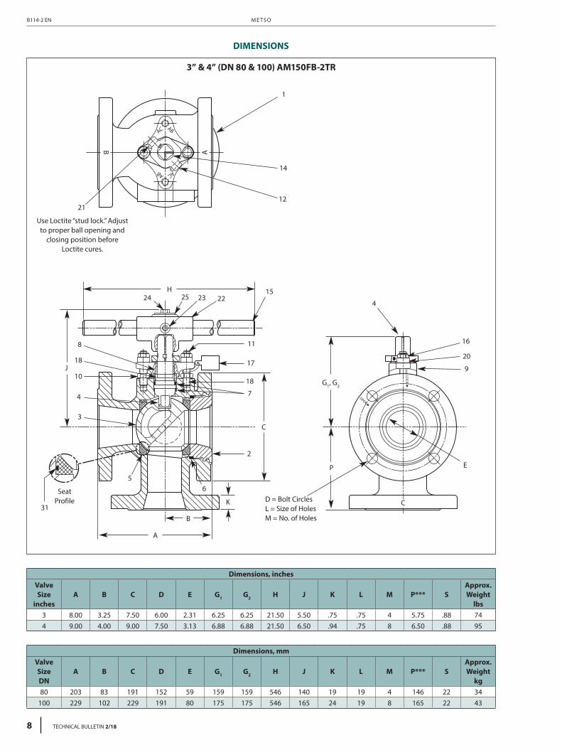
3” & 4” (DN 80 & 100) AM150FB-2TR
1
14
12
H24 25 23 22
15
11
17
18
7
2
C
P E
CD = Bolt CirclesL = Size of HolesM = No. of Holes
K
A
B
J
8
18
10
4
3
56
31
21
B A
Use Loctite “stud lock.” Adjustto proper ball opening and
closing position beforeLoctite cures.
SeatProfile
4
16
20
9
G1, G2
Dimensions, inchesValve Size
inchesA B C D E G1 G2 H J K L M P*** S
Approx. Weight
lbs3 8.00 3.25 7.50 6.00 2.31 6.25 6.25 21.50 5.50 .75 .75 4 5.75 .88 744 9.00 4.00 9.00 7.50 3.13 6.88 6.88 21.50 6.50 .94 .75 8 6.50 .88 95
Dimensions, mmValve Size DN
A B C D E G1 G2 H J K L M P*** SApprox. Weight
kg80 203 83 191 152 59 159 159 546 140 19 19 4 146 22 34
100 229 102 229 191 80 175 175 546 165 24 19 8 165 22 43
DIMENSIONS
M E T S OB114-2 EN
8 TECHNICAL BULLETIN 2/18
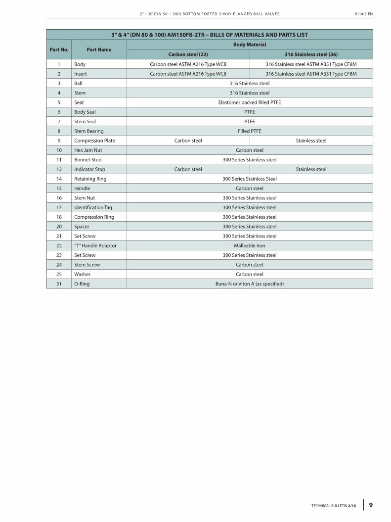
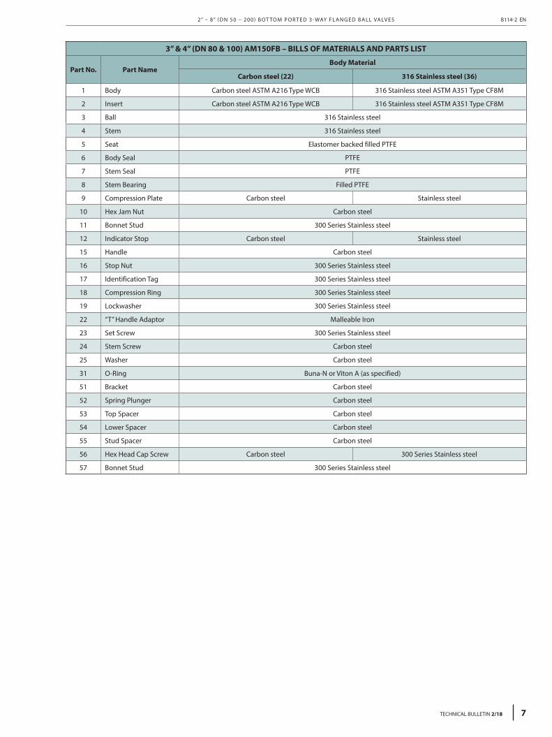
3” & 4” (DN 80 & 100) AM150FB-2TR – BILLS OF MATERIALS AND PARTS LIST
Part No. Part NameBody Material
Carbon steel (22) 316 Stainless steel (36)
1 Body Carbon steel ASTM A216 Type WCB 316 Stainless steel ASTM A351 Type CF8M
2 Insert Carbon steel ASTM A216 Type WCB 316 Stainless steel ASTM A351 Type CF8M
3 Ball 316 Stainless steel
4 Stem 316 Stainless steel
5 Seat Elastomer backed filled PTFE
6 Body Seal PTFE
7 Stem Seal PTFE
8 Stem Bearing Filled PTFE
9 Compression Plate Carbon steel Stainless steel
10 Hex Jam Nut Carbon steel
11 Bonnet Stud 300 Series Stainless steel
12 Indicator Stop Carbon steel Stainless steel
14 Retaining Ring 300 Series Stainless Steel
15 Handle Carbon steel
16 Stem Nut 300 Series Stainless steel
17 Identification Tag 300 Series Stainless steel
18 Compression Ring 300 Series Stainless steel
20 Spacer 300 Series Stainless steel
21 Set Screw 300 Series Stainless steel
22 “T” Handle Adaptor Malleable Iron
23 Set Screw 300 Series Stainless steel
24 Stem Screw Carbon steel
25 Washer Carbon steel
31 O-Ring Buna-N or Viton A (as specified)
2” – 8” ( D N 50 – 200 ) B OT TO M P O R T E D 3 - WAY F L A N G E D B A L L VA LV E S B114-2 EN
TECHNICAL BULLETIN 2/18 9
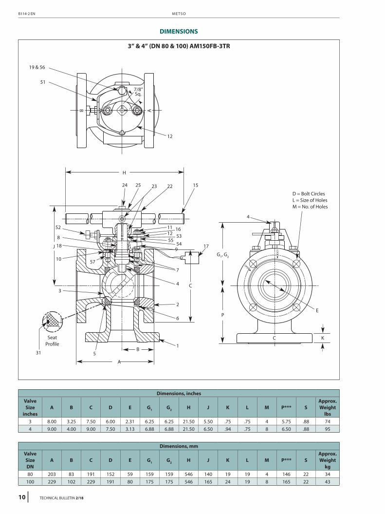
19 & 56
51
12
H
24 25 23 22 15
52
J
10 57
3
31 5
1
6
2
4
4
7
954
5553121611
17
C
P
C
E
K
A
B
18
8
B A
7/8”Sq.
3” & 4” (DN 80 & 100) AM150FB-3TR
DIMENSIONS
D = Bolt CirclesL = Size of HolesM = No. of Holes
SeatProfile
G1, G2
Dimensions, inchesValve Size
inchesA B C D E G1 G2 H J K L M P*** S
Approx. Weight
lbs3 8.00 3.25 7.50 6.00 2.31 6.25 6.25 21.50 5.50 .75 .75 4 5.75 .88 744 9.00 4.00 9.00 7.50 3.13 6.88 6.88 21.50 6.50 .94 .75 8 6.50 .88 95
Dimensions, mmValve Size DN
A B C D E G1 G2 H J K L M P*** SApprox. Weight
kg80 203 83 191 152 59 159 159 546 140 19 19 4 146 22 34
100 229 102 229 191 80 175 175 546 165 24 19 8 165 22 43
M E T S OB114-2 EN
10 TECHNICAL BULLETIN 2/18
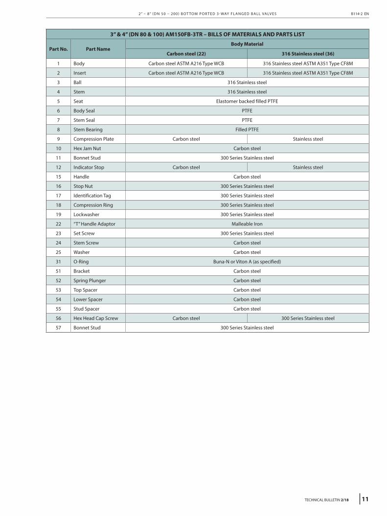
3” & 4” (DN 80 & 100) AM150FB-3TR – BILLS OF MATERIALS AND PARTS LIST
Part No. Part NameBody Material
Carbon steel (22) 316 Stainless steel (36)
1 Body Carbon steel ASTM A216 Type WCB 316 Stainless steel ASTM A351 Type CF8M
2 Insert Carbon steel ASTM A216 Type WCB 316 Stainless steel ASTM A351 Type CF8M
3 Ball 316 Stainless steel
4 Stem 316 Stainless steel
5 Seat Elastomer backed filled PTFE
6 Body Seal PTFE
7 Stem Seal PTFE
8 Stem Bearing Filled PTFE
9 Compression Plate Carbon steel Stainless steel
10 Hex Jam Nut Carbon steel
11 Bonnet Stud 300 Series Stainless steel
12 Indicator Stop Carbon steel Stainless steel
15 Handle Carbon steel
16 Stop Nut 300 Series Stainless steel
17 Identification Tag 300 Series Stainless steel
18 Compression Ring 300 Series Stainless steel
19 Lockwasher 300 Series Stainless steel
22 “T” Handle Adaptor Malleable Iron
23 Set Screw 300 Series Stainless steel
24 Stem Screw Carbon steel
25 Washer Carbon steel
31 O-Ring Buna-N or Viton A (as specified)
51 Bracket Carbon steel
52 Spring Plunger Carbon steel
53 Top Spacer Carbon steel
54 Lower Spacer Carbon steel
55 Stud Spacer Carbon steel
56 Hex Head Cap Screw Carbon steel 300 Series Stainless steel
57 Bonnet Stud 300 Series Stainless steel
2” – 8” ( D N 50 – 200 ) B OT TO M P O R T E D 3 - WAY F L A N G E D B A L L VA LV E S B114-2 EN
TECHNICAL BULLETIN 2/18 11
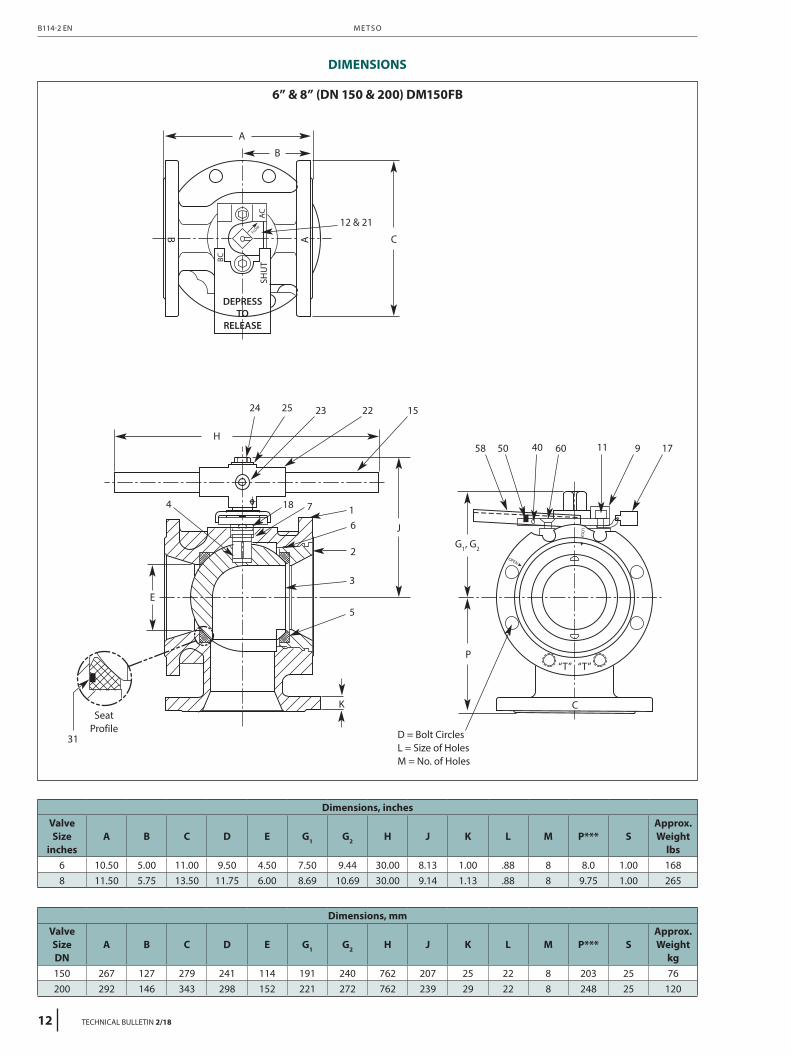
6” & 8” (DN 150 & 200) DM150FB
DIMENSIONS
Dimensions, inchesValve Size
inchesA B C D E G1 G2 H J K L M P*** S
Approx. Weight
lbs6 10.50 5.00 11.00 9.50 4.50 7.50 9.44 30.00 8.13 1.00 .88 8 8.0 1.00 1688 11.50 5.75 13.50 11.75 6.00 8.69 10.69 30.00 9.14 1.13 .88 8 9.75 1.00 265
Dimensions, mmValve Size DN
A B C D E G1 G2 H J K L M P*** SApprox. Weight
kg150 267 127 279 241 114 191 240 762 207 25 22 8 203 25 76200 292 146 343 298 152 221 272 762 239 29 22 8 248 25 120
31
A
H
24 25 23 22
18 7 16
2
3
5
K
E
4
15
58 50 40 60 11 9 17
J
P“T” “T”
C
A
B
B C
12 & 21
SeatProfile
G1, G2
D = Bolt CirclesL = Size of HolesM = No. of Holes
M E T S OB114-2 EN
12 TECHNICAL BULLETIN 2/18
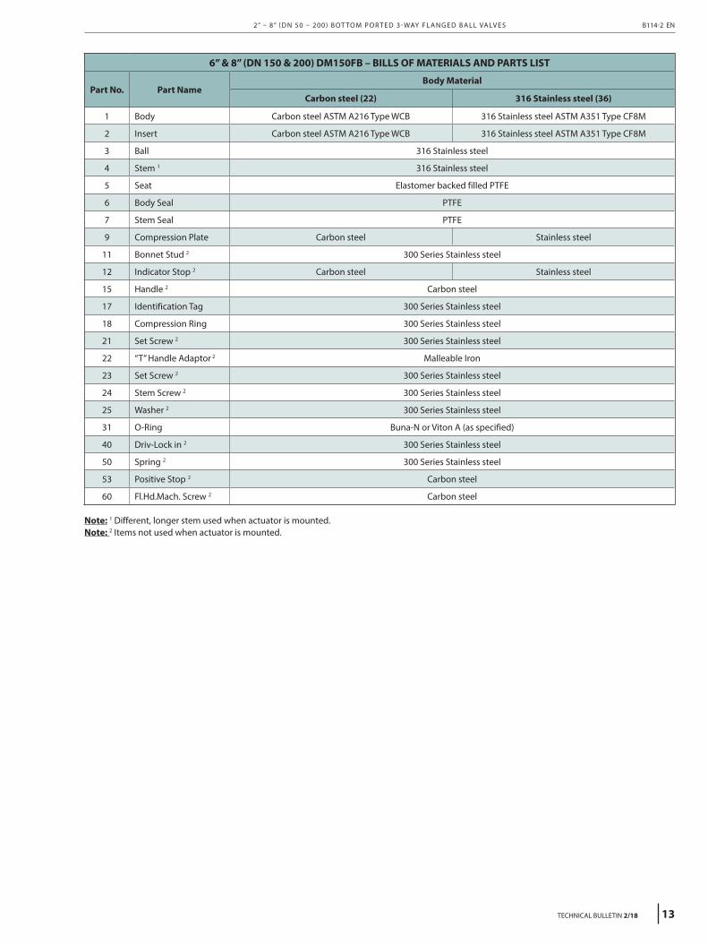
6” & 8” (DN 150 & 200) DM150FB – BILLS OF MATERIALS AND PARTS LIST
Part No. Part NameBody Material
Carbon steel (22) 316 Stainless steel (36)
1 Body Carbon steel ASTM A216 Type WCB 316 Stainless steel ASTM A351 Type CF8M
2 Insert Carbon steel ASTM A216 Type WCB 316 Stainless steel ASTM A351 Type CF8M
3 Ball 316 Stainless steel
4 Stem 1 316 Stainless steel
5 Seat Elastomer backed filled PTFE
6 Body Seal PTFE
7 Stem Seal PTFE
9 Compression Plate Carbon steel Stainless steel
11 Bonnet Stud 2 300 Series Stainless steel
12 Indicator Stop 2 Carbon steel Stainless steel
15 Handle 2 Carbon steel
17 Identification Tag 300 Series Stainless steel
18 Compression Ring 300 Series Stainless steel
21 Set Screw 2 300 Series Stainless steel
22 “T” Handle Adaptor 2 Malleable Iron
23 Set Screw 2 300 Series Stainless steel
24 Stem Screw 2 300 Series Stainless steel
25 Washer 2 300 Series Stainless steel
31 O-Ring Buna-N or Viton A (as specified)
40 Driv-Lock in 2 300 Series Stainless steel
50 Spring 2 300 Series Stainless steel
53 Positive Stop 2 Carbon steel
60 Fl.Hd.Mach. Screw 2 Carbon steel
Note: 1 Different, longer stem used when actuator is mounted.Note: 2 Items not used when actuator is mounted.
2” – 8” ( D N 50 – 200 ) B OT TO M P O R T E D 3 - WAY F L A N G E D B A L L VA LV E S B114-2 EN
TECHNICAL BULLETIN 2/18 13
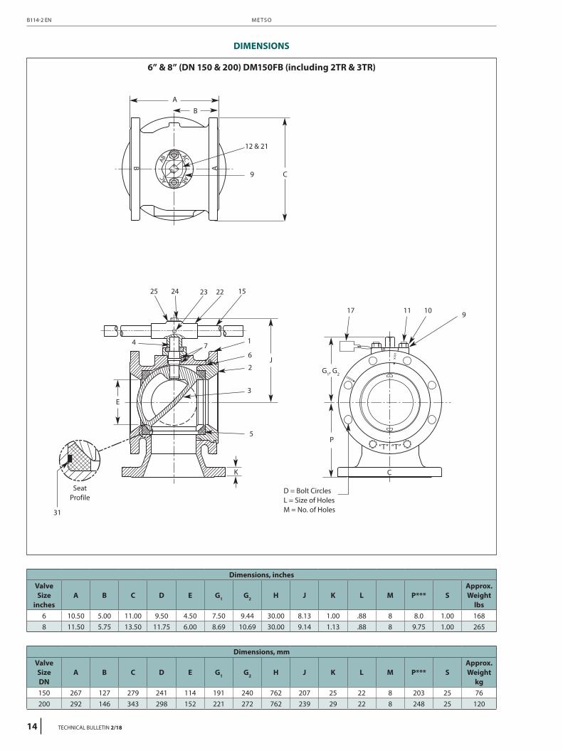
DIMENSIONS
6” & 8” (DN 150 & 200) DM150FB (including 2TR & 3TR)
31
A
2425 23 22
18
71
6
2
3
5
K
E
4
15
9
1011 917
J
P“T” “T”
C
A
B
B
C
12 & 21
SeatProfile
G1, G2
D = Bolt CirclesL = Size of HolesM = No. of Holes
Dimensions, inchesValve Size
inchesA B C D E G1 G2 H J K L M P*** S
Approx. Weight
lbs6 10.50 5.00 11.00 9.50 4.50 7.50 9.44 30.00 8.13 1.00 .88 8 8.0 1.00 1688 11.50 5.75 13.50 11.75 6.00 8.69 10.69 30.00 9.14 1.13 .88 8 9.75 1.00 265
Dimensions, mmValve Size DN
A B C D E G1 G2 H J K L M P*** SApprox. Weight
kg150 267 127 279 241 114 191 240 762 207 25 22 8 203 25 76200 292 146 343 298 152 221 272 762 239 29 22 8 248 25 120
M E T S OB114-2 EN
14 TECHNICAL BULLETIN 2/18
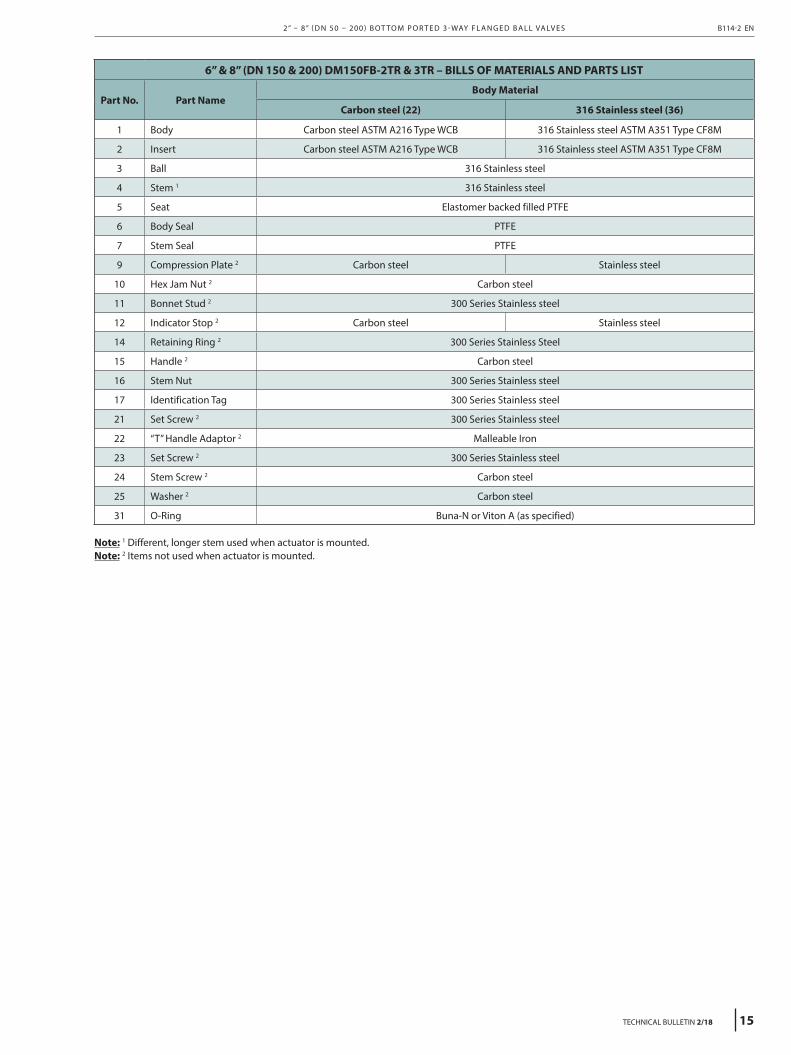
6” & 8” (DN 150 & 200) DM150FB-2TR & 3TR – BILLS OF MATERIALS AND PARTS LIST
Part No. Part NameBody Material
Carbon steel (22) 316 Stainless steel (36)
1 Body Carbon steel ASTM A216 Type WCB 316 Stainless steel ASTM A351 Type CF8M
2 Insert Carbon steel ASTM A216 Type WCB 316 Stainless steel ASTM A351 Type CF8M
3 Ball 316 Stainless steel
4 Stem 1 316 Stainless steel
5 Seat Elastomer backed filled PTFE
6 Body Seal PTFE
7 Stem Seal PTFE
9 Compression Plate 2 Carbon steel Stainless steel
10 Hex Jam Nut 2 Carbon steel
11 Bonnet Stud 2 300 Series Stainless steel
12 Indicator Stop 2 Carbon steel Stainless steel
14 Retaining Ring 2 300 Series Stainless Steel
15 Handle 2 Carbon steel
16 Stem Nut 300 Series Stainless steel
17 Identification Tag 300 Series Stainless steel
21 Set Screw 2 300 Series Stainless steel
22 “T” Handle Adaptor 2 Malleable Iron
23 Set Screw 2 300 Series Stainless steel
24 Stem Screw 2 Carbon steel
25 Washer 2 Carbon steel
31 O-Ring Buna-N or Viton A (as specified)
Note: 1 Different, longer stem used when actuator is mounted.Note: 2 Items not used when actuator is mounted.
2” – 8” ( D N 50 – 200 ) B OT TO M P O R T E D 3 - WAY F L A N G E D B A L L VA LV E S B114-2 EN
TECHNICAL BULLETIN 2/18 15
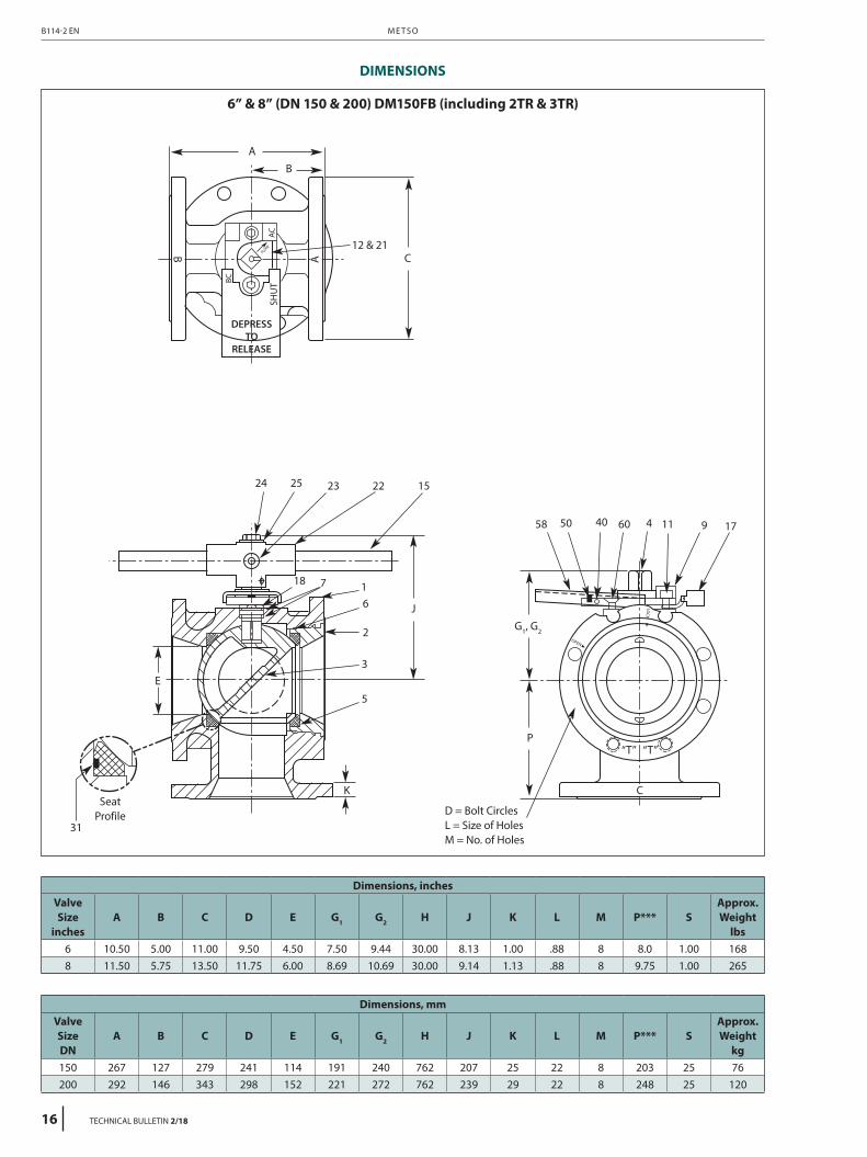
DIMENSIONS
6” & 8” (DN 150 & 200) DM150FB (including 2TR & 3TR)
Dimensions, inchesValve Size
inchesA B C D E G1 G2 H J K L M P*** S
Approx. Weight
lbs6 10.50 5.00 11.00 9.50 4.50 7.50 9.44 30.00 8.13 1.00 .88 8 8.0 1.00 1688 11.50 5.75 13.50 11.75 6.00 8.69 10.69 30.00 9.14 1.13 .88 8 9.75 1.00 265
Dimensions, mmValve Size DN
A B C D E G1 G2 H J K L M P*** SApprox. Weight
kg150 267 127 279 241 114 191 240 762 207 25 22 8 203 25 76200 292 146 343 298 152 221 272 762 239 29 22 8 248 25 120
31
A
24 25 23 22
18 7 16
2
3
5
K
E
15
58 50 40 60 114 9 17
J
P“T” “T”
C
A
B
B C12 & 21
SeatProfile
G1, G2
D = Bolt CirclesL = Size of HolesM = No. of Holes
M E T S OB114-2 EN
16 TECHNICAL BULLETIN 2/18

6” & 8” (DN 150 & 200) DM150FB – BILLS OF MATERIALS AND PARTS LIST
Part No. Part NameBody Material
Carbon steel (22) 316 Stainless steel (36)
1 Body Carbon steel ASTM A216 Type WCB 316 Stainless steel ASTM A351 Type CF8M
2 Insert Carbon steel ASTM A216 Type WCB 316 Stainless steel ASTM A351 Type CF8M
3 Ball 316 Stainless steel
4 Stem 1 316 Stainless steel
5 Seat Elastomer backed filled PTFE
6 Body Seal PTFE
7 Stem Seal PTFE
9 Compression Plate Carbon steel Stainless steel
11 Bonnet Stud 2 300 Series Stainless steel
12 Indicator Stop 2 Carbon steel Stainless steel
15 Handle 2 Carbon steel
17 Identification Tag 300 Series Stainless steel
18 Compression Ring 300 Series Stainless steel
21 Set Screw 2 300 Series Stainless steel
22 “T” Handle Adaptor 2 Malleable Iron
23 Set Screw 2 300 Series Stainless steel
24 Stem Screw 2 Carbon steel
25 Washer 2 Carbon steel
31 O-Ring Buna-N or Viton A (as specified)
40 Driv-Lock in 2 300 Series Stainless steel
50 Spring 2 300 Series Stainless steel
53 Positive Stop 2 Carbon steel
60 Fl.Hd.Mach. Screw 2 300 Series Stainless steel
Note: 1 Different, longer stem used when actuator is mounted.Note: 2 Items not used when actuator is mounted.
2” – 8” ( D N 50 – 200 ) B OT TO M P O R T E D 3 - WAY F L A N G E D B A L L VA LV E S B114-2 EN
TECHNICAL BULLETIN 2/18 17
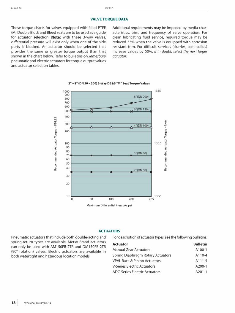
VALVE TORQUE DATA
These torque charts for valves equipped with filled PTFE (M) Double Block and Bleed seats are to be used as a guide for actuator selection. Note: with these 3-way valves, differential pressure will exist only when one of the side ports is blocked. An actuator should be selected that provides the same or greater torque output than that shown in the chart below. Refer to bulletins on Jamesbury pneumatic and electric actuators for torque output values and actuator selection tables.
Additional requirements may be imposed by media char-acteristics, trim, and frequency of valve operation. For clean lubricating fluid service, required torque may be reduced 33% when the valve is equipped with corrosion resistant trim. For difficult services (slurries, semi-solids) increase values by 50%. If in doubt, select the next larger actuator.
2” – 8” (DN 50 – 200) 3-Way DB&B “M” Seat Torque Values
Reco
mm
ende
d Ac
tuat
or To
rque
– F
T•LB
S
Reco
mm
ende
d Ac
tuat
or To
rque
– N
•m
Maximum Differential Pressure, psi
1000900800700600500
400
300
200
100908070605040
30
20
100 50 100 200 285
13.55
135.5
1355
ACTUATORS
Pneumatic actuators that include both double-acting and spring-return types are available. Metso Brand actuators can only be used with AM150FB-2TR and DM150FB-2TR (90° rotation) valves. Electric actuators are available in both watertight and hazardous location models.
For description of actuator types, see the following bulletins:
Actuator BulletinManual Gear Actuators A100-1Spring Diaphragm Rotary Actuators A110-4VPVL Rack & Pinion Actuators A111-5V-Series Electric Actuators A200-1ADC-Series Electric Actuators A201-1
8” (DN 200)
6” (DN 150)
4” (DN 100)
3” (DN 80)
2” (DN 50)
M E T S OB114-2 EN
18 TECHNICAL BULLETIN 2/18
1 Size inches 21 3 4 6 8
DN 50 80 100 150 200
2 Body StyleAM 2” – 4” (DN 50 – 100)DM 6” – 8” (DN 150 – 200)
3 Body Rating150 ANSI Class 150
4 ConfigurationFB Bottom ported flanged body
5 Configuration– Basic Design
2TR 2 position valve with dual ported ball3TR 3 position valve with dual ported ball
6 ConfigurationDBB Double block and bleed seats
7 Body/Trim Material2236 Carbon steel body/316 Stainless steel trim3600 316 Stainless steel body/316 Stainless steel trim
8 Seat MaterialM Filled PTFE
9 Seal MaterialT PTFE
10 O-Ring / Stem Selection2” thru 8”
52 Buna N53 Viton
6” thru 8”AO Buna N with operating stemDO Viton with operating stem
1 Not available with 2TR/3TR ball
WARNING:As the use of the valve is application specific, a number of factors should be taken into account when selecting a valve for a given application. Therefore, some of the situations in which the valves are used are outside the scope of this manual. If you have any questions concerning the use, application or compatibility of the valve with the intended service, contact Metso for more information.
HOW TO ORDER
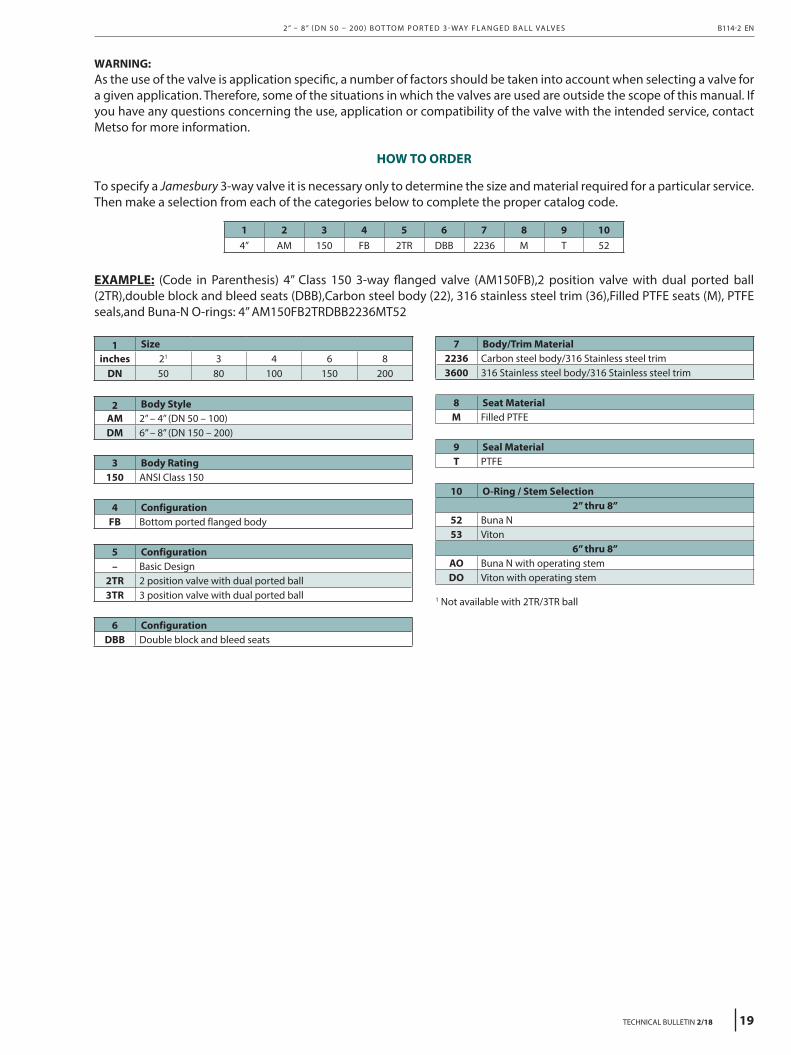
To specify a Jamesbury 3-way valve it is necessary only to determine the size and material required for a particular service. Then make a selection from each of the categories below to complete the proper catalog code.
1 2 3 4 5 6 7 8 9 104” AM 150 FB 2TR DBB 2236 M T 52
EXAMPLE: (Code in Parenthesis) 4” Class 150 3-way flanged valve (AM150FB),2 position valve with dual ported ball (2TR),double block and bleed seats (DBB),Carbon steel body (22), 316 stainless steel trim (36),Filled PTFE seats (M), PTFE seals,and Buna-N O-rings: 4” AM150FB2TRDBB2236MT52
2” – 8” ( D N 50 – 200 ) B OT TO M P O R T E D 3 - WAY F L A N G E D B A L L VA LV E S B114-2 EN
TECHNICAL BULLETIN 2/18 19

Subject to change without prior notice.
Metso Flow Control Inc.Europe, Vanha Porvoontie 229, P.O. Box 304, FI-01301 VANTAA, Finland.Tel. +358 20 483 150. Fax +358 20 483 151North America, 44 Bowditch Drive, P.O. Box 8044, Shrewsbury, MA 01545, USA. Tel. +1 508 852 0200. Fax +1 508 852 8172South America, Av. Independéncia, 2500- Iporanga, 18087-101, Sorocaba-São Paulo, Brazil.Tel. +55 15 2102 9700. Fax +55 15 2102 9748/49
Asia Paci�c, 238B Thomson Road, #17-01 Novena Square Tower B, Singapore 307685.Tel. +65 6511 1011. Fax +65 6250 0830
China, 11/F, China Youth Plaza, No.19 North Rd of East 3rd Ring Rd, Chaoyang District, Beijing 100020, China. Tel. +86 10 6566 6600. Fax +86 10 6566 2583
Middle East, Roundabout 8, Unit AB-07, P.O. Box 17175, Jebel Ali Freezone, Dubai,United Arab Emirates. Tel. +971 4 883 6974. Fax +971 4 883 6836
www.metso.com/valves