20 xtr manual - cb tricks - home page · citizens band and class c remote control frequencies.) ......
TRANSCRIPT
26
Accessory Order Form
Tax TableOhio, Wisconsin residents add 5%Indiana, Michigan residents add 6 %Illinois residents add 8.75%California residents add 7.25%
Please print clearlyName___________________________________________________Address (No P.O. Box)_____________________________________City____________________________________State____________Zip_____________Telephone (____)__________________________Credit Card No._________________________Exp. Date_________Customer Signature__________________________________Circle One: Visa MasterCard Discover
Subtotal
(Tax if applicable)
Shipping/handling
Total
Shipping & Handling*Amount of Shipping/Order Handling$10.00 or less $3.00 $10.01-$25.00 $5.50 $25.01-$50.00 $7.50$50.01-$90.00 $10.50$90.01-$130.00 $13.50$130.01-$200.00 $16.50$200.01 plus 10% of purchase
*For AK, HI and PR add additional$26.95 for FedEx Next Day or$10.95 for FedEx 2nd Day.Excludesweekend and holiday shipments.
Please allow 2-3 weeks fordelivery in the U.S. Prices subjectto change without notice.
Item # Description Cost Ea. Qty. Amount251-199-9-001 Replacement
Mounting Bracket
634-081-9-001 Replacement Thumb Screws
741-080-9-001 Replacement Microphone Bracket
HG M84 4 Pin Premium Noise-Cancelling Microphone
HG M84W 4 Pin Premium Noise-Cancelling Microphone Wood Grain
HG M85 5 Pin Premium Noise-Cancelling Microphone
HG M73 Replacement Dynamic Microphone
HG M75 4 Pin Power Microphone
HG M77 Noise Canceling Microphone
HG S100 Dynamic External Speaker
HG S300 Noise Canceling External Speaker
HG S500 Noise Canceling With Talk Back External Speaker
The Cobra® line ofquality products alsoincludes:• CB Radios
• microTALK® Radios
• Radar/Laser Detectors
• Safety Alert® Traffic Warning Systems
• Accessories
• GPS (Global PositioningSystem)
• HighGear™ Accessories
• Power Inverters
• VHF Marine Radios
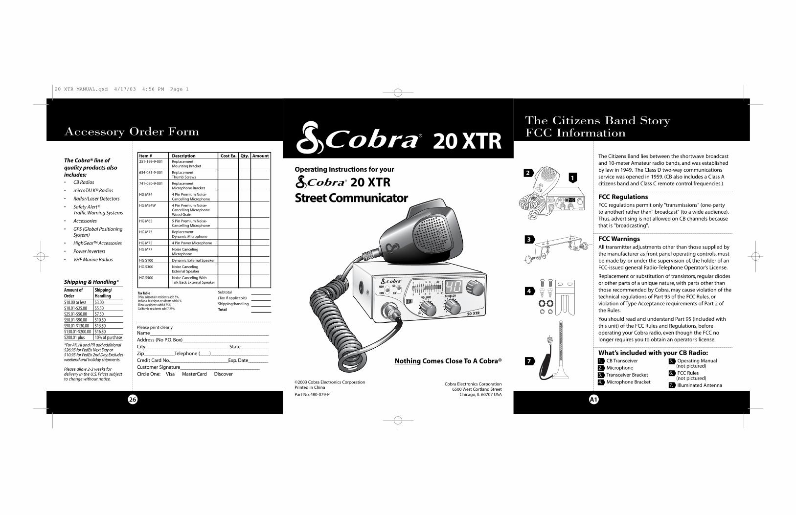
1. CB Transceiver
2. Microphone
3. Transceiver Bracket
4. Microphone Bracket
5. Operating Manual(not pictured)
6. FCC Rules(not pictured)
7. Illuminated Antenna
CB Tranceiver
A1
The Citizens Band StoryFCC Information
4
7
21
3
Nothing Comes Close To A Cobra®
20 XTRStreet Communicator
Operating Instructions for your
20 XTRThe Citizens Band lies between the shortwave broadcastand 10-meter Amateur radio bands, and was establishedby law in 1949. The Class D two-way communicationsservice was opened in 1959. (CB also includes a Class Acitizens band and Class C remote control frequencies.)
FCC RegulationsFCC regulations permit only "transmissions" (one-party to another) rather than" broadcast" (to a wide audience).Thus, advertising is not allowed on CB channels because that is "broadcasting".
FCC WarningsAll transmitter adjustments other than those supplied by the manufacturer as front panel operating controls, mustbe made by, or under the supervision of, the holder of an FCC-issued general Radio-Telephone Operator’s License.
Replacement or substitution of transistors, regular diodesor other parts of a unique nature, with parts other thanthose recommended by Cobra, may cause violation of thetechnical regulations of Part 95 of the FCC Rules, orviolation of Type Acceptance requirements of Part 2 ofthe Rules.
You should read and understand Part 95 (included withthis unit) of the FCC Rules and Regulations, beforeoperating your Cobra radio, even though the FCC nolonger requires you to obtain an operator’s license.
What’s included with your CB Radio:
©2003 Cobra Electronics CorporationPrinted in China
Part No. 480-079-P
Cobra Electronics Corporation6500 West Cortland Street
Chicago, IL 60707 USA
20 XTR MANUAL.qxd 4/17/03 4:56 PM Page 1

25
OptionalAccessories You can find accessories atyour local Cobra® dealer, or inthe U.S.A. you can order directly from Cobra®.
Ordering From U.S.A.Call 773-889-3087 for pricingor visit www.cobra.com.
For credit card ordersComplete and mail this orderform to:Cobra® Electronics Attn: Accessories Department 6500 West Cortland StreetChicago, IL 60707 USA.
Or fax the completed form tous at 773-622-2269.
You may also order by phoneby calling 773-889-3087 (press1 from the main menu) 8:00a.m. to 6:00 p.m. CT, Mondaythrough Friday.
To order online please visit our website:www.cobra.com
Accessories
Dynamic External SpeakerHG S100
Noise Canceling ExternalSpeakerHG S300
Noise Canceling With TalkBack External SpeakerHG S500
PA
ANT
13.8V DC
EXT
A2
Controls and Indicators
Thank you for purchasing the Cobra 20 XTR RadioTransceiver. Properly used, this Cobra product will giveyou many years of reliable service.
Customer AssistanceIn this user’s manual, you should find all theinformation you need to operate your radio. If yourequire further assistance after reading this manual,Cobra® Electronics offers the following customerassistance services:
For Assistance In the U.S.A.Automated Help DeskEnglish only. 24 hours a day, 7 days a week 773-889-3087 (phone).
Customer Assistance OperatorsEnglish and Spanish. 8:00 a.m. to 6:00 p.m. CT,Monday through Friday (except holidays) 773-889-3087 (phone).
QuestionsEnglish and Spanish. Faxes can be received at 773-622-2269 (fax).
Technical AssistanceEnglish only. www.cobra.com (on-line:Frequently Asked Questions).English and Spanish. [email protected] (e-mail).
For Assistance Outside the U.S.A.Contact Your Local Dealer
A3
1
7 6
Our Thanks to YouCustomer Assistance
5
10
Front Side
1. Microphone Connector.
2. Off/On/Volume.
3. Squelch.
4. Channel 9/NOR
5. CB/PA
6. Channel SelectorButton.
7. LED Channel Display.
8. S/RF Power Meter.
9. TX Indicator LED.
10. Microphone
Back Side
11. Antenna Connector
12. Public Address
13. Power Cord
14. External SpeakerConnector
4 8
11 13
1412
2 3
9
CustomerAssistance
20 XTR MANUAL.qxd 4/17/03 4:56 PM Page 4
1
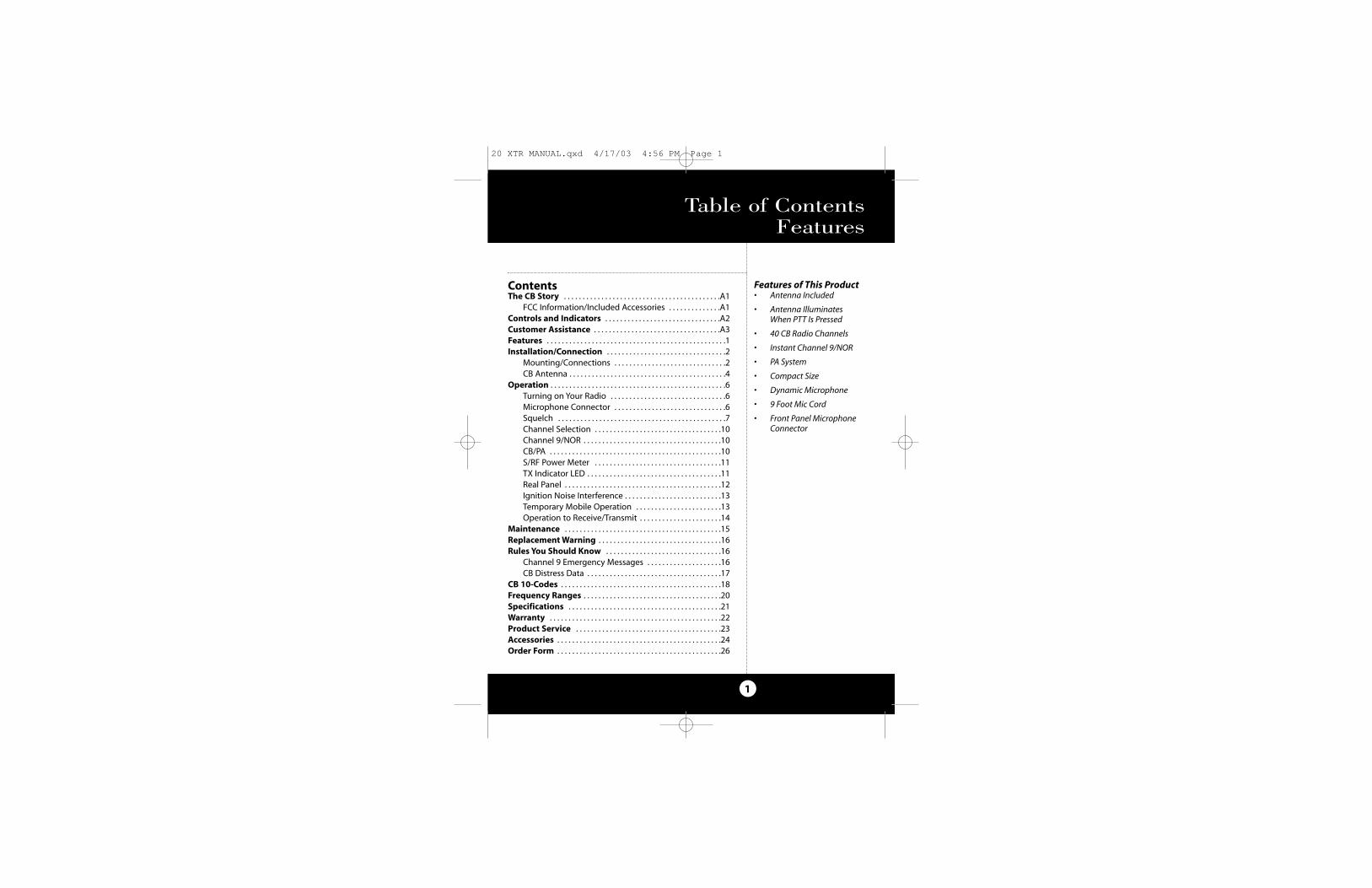
ContentsThe CB Story . . . . . . . . . . . . . . . . . . . . . . . . . . . . . . . . . . . . . . . . . .A1
FCC Information/Included Accessories . . . . . . . . . . . . . .A1Controls and Indicators . . . . . . . . . . . . . . . . . . . . . . . . . . . . . . .A2Customer Assistance . . . . . . . . . . . . . . . . . . . . . . . . . . . . . . . . . .A3Features . . . . . . . . . . . . . . . . . . . . . . . . . . . . . . . . . . . . . . . . . . . . . . . .1Installation/Connection . . . . . . . . . . . . . . . . . . . . . . . . . . . . . . . .2
Mounting/Connections . . . . . . . . . . . . . . . . . . . . . . . . . . . . . .2CB Antenna . . . . . . . . . . . . . . . . . . . . . . . . . . . . . . . . . . . . . . . . . .4
Operation . . . . . . . . . . . . . . . . . . . . . . . . . . . . . . . . . . . . . . . . . . . . . . .6Turning on Your Radio . . . . . . . . . . . . . . . . . . . . . . . . . . . . . . .6Microphone Connector . . . . . . . . . . . . . . . . . . . . . . . . . . . . . .6Squelch . . . . . . . . . . . . . . . . . . . . . . . . . . . . . . . . . . . . . . . . . . . . .7Channel Selection . . . . . . . . . . . . . . . . . . . . . . . . . . . . . . . . . .10Channel 9/NOR . . . . . . . . . . . . . . . . . . . . . . . . . . . . . . . . . . . . .10CB/PA . . . . . . . . . . . . . . . . . . . . . . . . . . . . . . . . . . . . . . . . . . . . . .10S/RF Power Meter . . . . . . . . . . . . . . . . . . . . . . . . . . . . . . . . . .11TX Indicator LED . . . . . . . . . . . . . . . . . . . . . . . . . . . . . . . . . . . .11Real Panel . . . . . . . . . . . . . . . . . . . . . . . . . . . . . . . . . . . . . . . . . .12Ignition Noise Interference . . . . . . . . . . . . . . . . . . . . . . . . . .13Temporary Mobile Operation . . . . . . . . . . . . . . . . . . . . . . .13Operation to Receive/Transmit . . . . . . . . . . . . . . . . . . . . . .14
Maintenance . . . . . . . . . . . . . . . . . . . . . . . . . . . . . . . . . . . . . . . . . .15Replacement Warning . . . . . . . . . . . . . . . . . . . . . . . . . . . . . . . . .16Rules You Should Know . . . . . . . . . . . . . . . . . . . . . . . . . . . . . . .16
Channel 9 Emergency Messages . . . . . . . . . . . . . . . . . . . .16CB Distress Data . . . . . . . . . . . . . . . . . . . . . . . . . . . . . . . . . . . .17
CB 10-Codes . . . . . . . . . . . . . . . . . . . . . . . . . . . . . . . . . . . . . . . . . . .18Frequency Ranges . . . . . . . . . . . . . . . . . . . . . . . . . . . . . . . . . . . . .20Specifications . . . . . . . . . . . . . . . . . . . . . . . . . . . . . . . . . . . . . . . . .21Warranty . . . . . . . . . . . . . . . . . . . . . . . . . . . . . . . . . . . . . . . . . . . . . .22Product Service . . . . . . . . . . . . . . . . . . . . . . . . . . . . . . . . . . . . . . .23Accessories . . . . . . . . . . . . . . . . . . . . . . . . . . . . . . . . . . . . . . . . . . . .24Order Form . . . . . . . . . . . . . . . . . . . . . . . . . . . . . . . . . . . . . . . . . . . .26
Features of This Product• Antenna Included
• Antenna IlluminatesWhen PTT Is Pressed
• 40 CB Radio Channels
• Instant Channel 9/NOR
• PA System
• Compact Size
• Dynamic Microphone
• 9 Foot Mic Cord
• Front Panel MicrophoneConnector
Table of ContentsFeatures
20 XTR MANUAL.qxd 4/17/03 4:56 PM Page 1
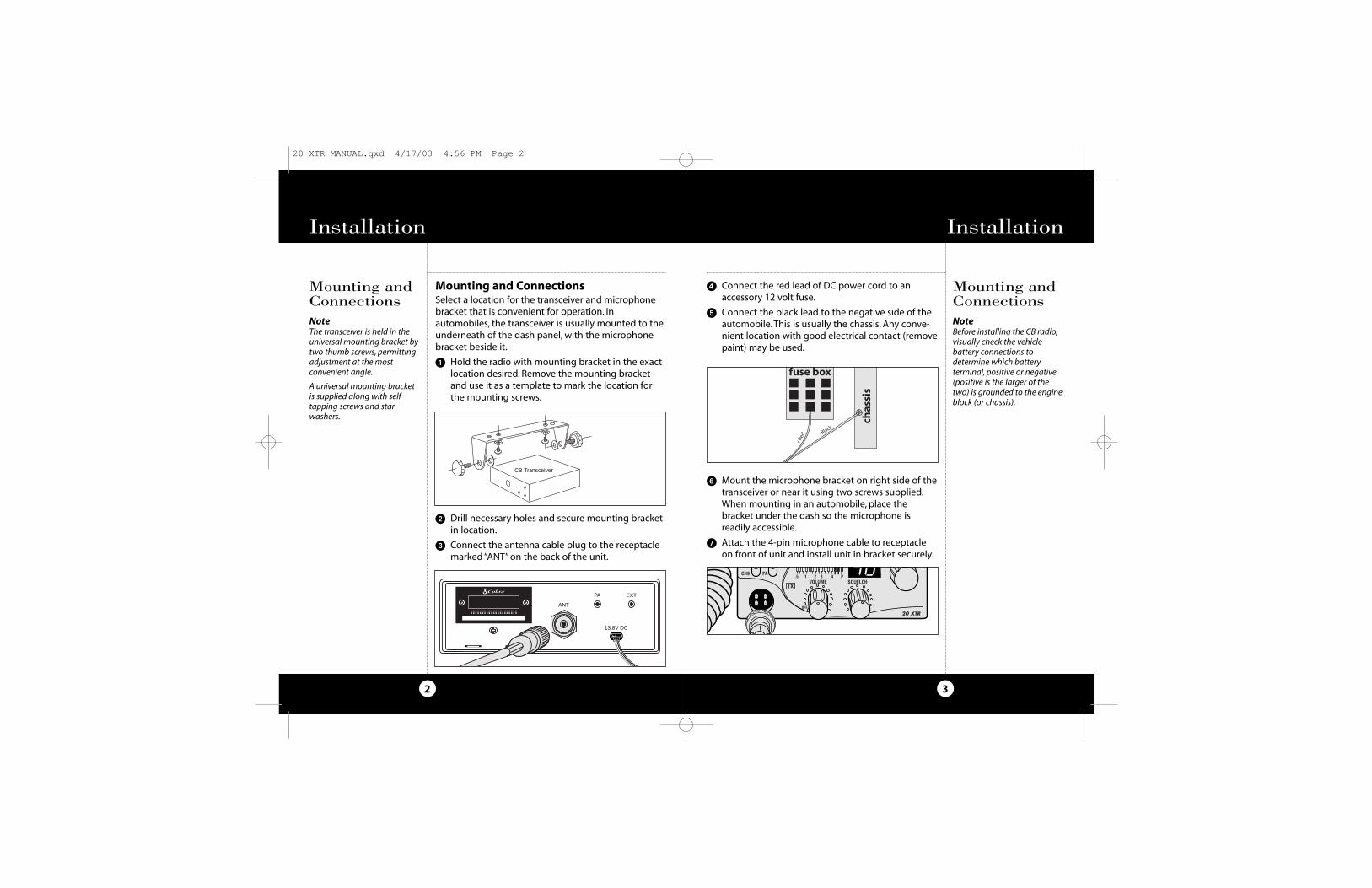
� Connect the red lead of DC power cord to anaccessory 12 volt fuse.
� Connect the black lead to the negative side of theautomobile. This is usually the chassis. Any conve-nient location with good electrical contact (removepaint) may be used.
� Mount the microphone bracket on right side of thetransceiver or near it using two screws supplied.When mounting in an automobile, place thebracket under the dash so the microphone isreadily accessible.
� Attach the 4-pin microphone cable to receptacleon front of unit and install unit in bracket securely.
Mounting and ConnectionsSelect a location for the transceiver and microphonebracket that is convenient for operation. Inautomobiles, the transceiver is usually mounted to theunderneath of the dash panel, with the microphonebracket beside it.
� Hold the radio with mounting bracket in the exactlocation desired. Remove the mounting bracketand use it as a template to mark the location forthe mounting screws.
� Drill necessary holes and secure mounting bracketin location.
� Connect the antenna cable plug to the receptaclemarked “ANT” on the back of the unit.
CB Tranceiver
EXT
ANT
13.8V DC
PA
3
Mounting andConnectionsNoteBefore installing the CB radio,visually check the vehiclebattery connections todetermine which batteryterminal, positive or negative(positive is the larger of thetwo) is grounded to the engineblock (or chassis).
2
Mounting andConnectionsNoteThe transceiver is held in theuniversal mounting bracket bytwo thumb screws, permittingadjustment at the mostconvenient angle.
A universal mounting bracketis supplied along with selftapping screws and starwashers.
OperationInstallation Installation
CB Transceiver
20 XTR MANUAL.qxd 4/17/03 4:56 PM Page 2
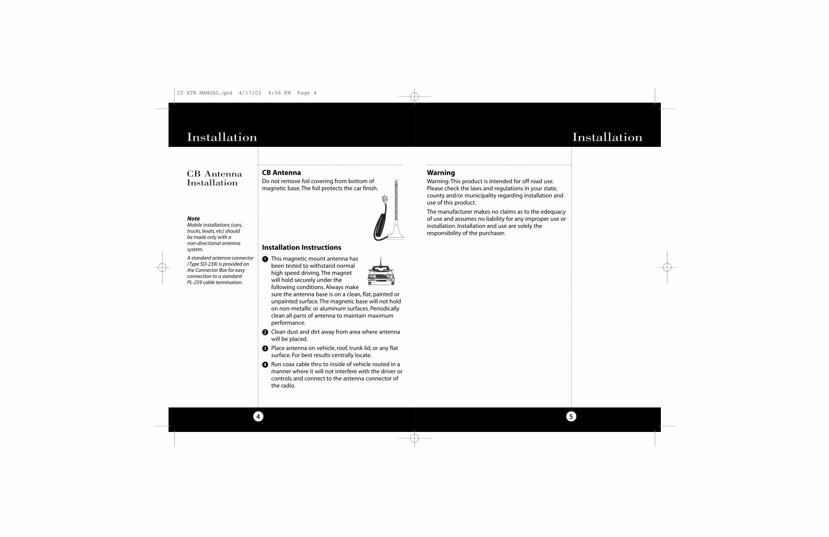
Installation Instructions
� This magnetic mount antenna hasbeen tested to withstand normalhigh speed driving. The magnetwill hold securely under thefollowing conditions. Always makesure the antenna base is on a clean, flat, painted orunpainted surface. The magnetic base will not holdon non-metallic or aluminum surfaces. Periodicallyclean all parts of antenna to maintain maximumperformance.
� Clean dust and dirt away from area where antennawill be placed.
� Place antenna on vehicle, roof, trunk lid, or any flatsurface. For best results centrally locate.
� Run coax cable thru to inside of vehicle routed in amanner where it will not interfere with the driver orcontrols and connect to the antenna connector ofthe radio.
5
WarningWarning: This product is intended for off road use.Please check the laws and regulations in your state,county and/or municipality regarding installation anduse of this product.
The manufacturer makes no claims as to the edequacyof use and assumes no liability for any improper use orinstallation. Installation and use are solely theresponsibility of the purchaser.
Installation
4
Installation
CB AntennaInstallation
NoteMobile installations (cars,trucks, boats, etc) should be made only with a non-directional antennasystem.
A standard antenna connector (Type SO-239) is provided onthe Connector Box for easyconnection to a standard PL-259 cable termination.
CB AntennaDo not remove foil covering from bottom of magnetic base. The foil protects the car finish.
20 XTR MANUAL.qxd 4/17/03 4:56 PM Page 4

7
SquelchThis control is used to cut off or eliminate receiverbackground noise in the absence of an incomingsignal. Adjust until the receiver noise disappears. Thiswill require the incoming signal to be slightly strongerthan average receiver noise. Further clockwise rotationwill increase the threshold level which a signal mustovercome in order to be heard. Only strong signals willbe heard at a maximum clockwise setting.
Squelch
Operation
6
Turning onTurn volume control clockwise to turn power on andset the desired listening volume.
Microphone Connector Allows for convenient removal of the microphone plugwhen storage is required. The microphone MUST beconnected to the unit at all times when in use, forproper operation.
Turning onYour Radio
Operation
SHIELD
AUDIO
RX
TX
1
23
4
MicrophoneConnector
20 XTR MANUAL.qxd 4/17/03 4:56 PM Page 6
NOISE
WEAK SIGNALS
MEDIUM SIGNALS
STRONG SIGNALS
GA
TE
CL
OS
ED
NOISE
WEAK SIGNALS
MEDIUM SIGNALS
STRONG SIGNALS
NOISE
WEAK SIGNALS
MEDIUM SIGNALS
STRONG SIGNALS
GA
TE
O
PE
N
NOISE
WEAK SIGNALS
MEDIUM SIGNALS
STRONG SIGNALS
NOISE
WEAK SIGNALS
MEDIUM SIGNALS
STRONG SIGNALS
GA
TE
9
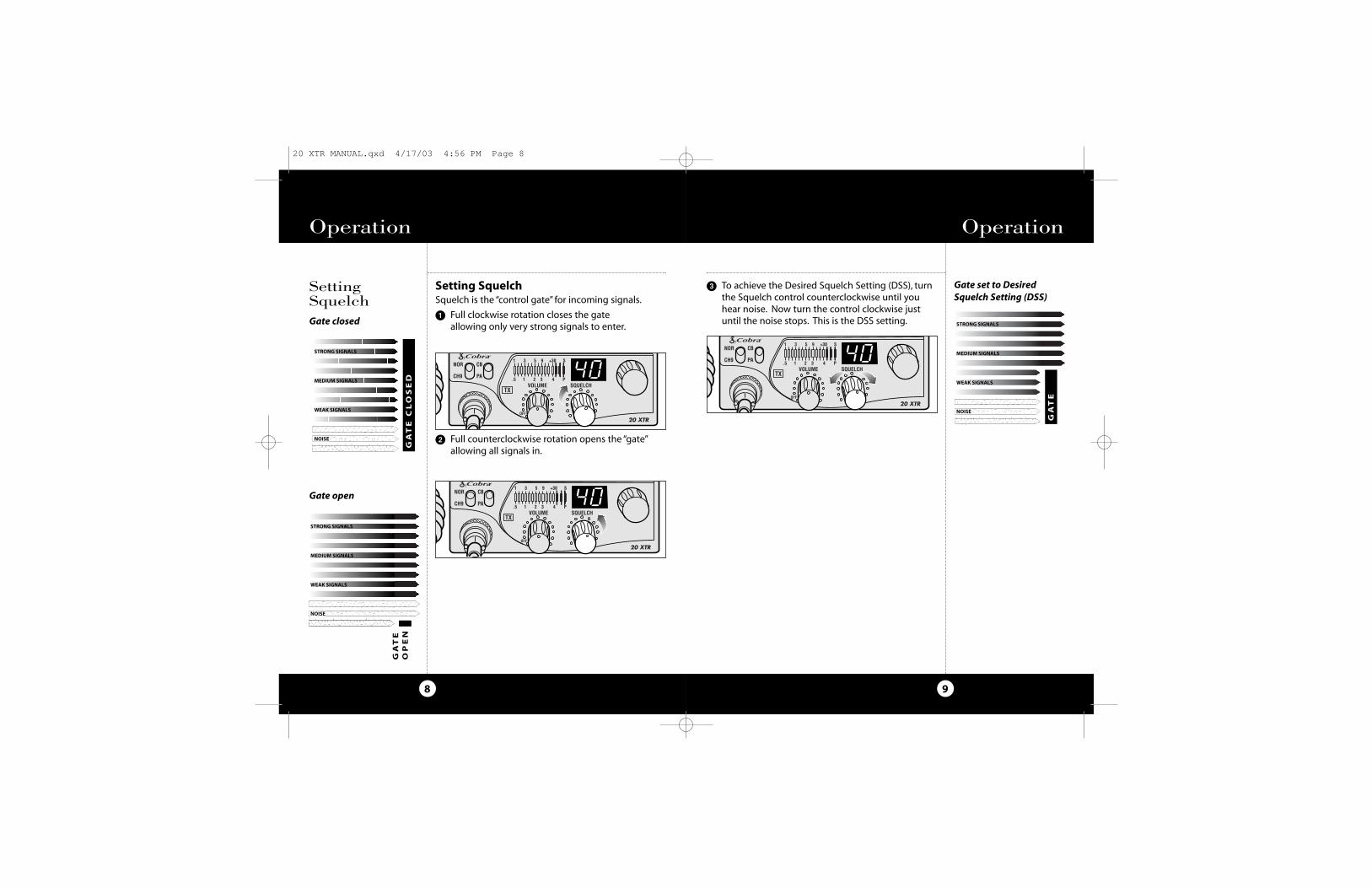
� To achieve the Desired Squelch Setting (DSS), turnthe Squelch control counterclockwise until youhear noise. Now turn the control clockwise justuntil the noise stops. This is the DSS setting.
Operation
8
Operation
Gate open
Gate set to Desired Squelch Setting (DSS)
Gate closed
SettingSquelch
Setting Squelch Squelch is the “control gate” for incoming signals.
� Full clockwise rotation closes the gate allowing only very strong signals to enter.
� Full counterclockwise rotation opens the “gate”allowing all signals in.
20 XTR MANUAL.qxd 4/17/03 4:56 PM Page 8
11
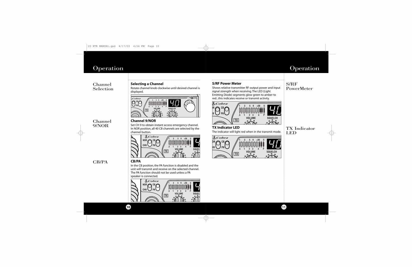
S/RF Power MeterShows relative transmitter RF output power and inputsignal strength when receiving. The LED (LightEmitting Diode) segments glow green to amber tored...this indicates receive or transmit activity.
TX Indicator LEDThe indicator will light red when in the transmit mode.
Operation
S/RFPowerMeter
TX IndicatorLED
ChannelSelection
10
Selecting a ChannelRotate channel knob clockwise until desired channel isdisplayed.
Channel 9/NORSet CH 9 to obtain instant access emergency channel.In NOR position, all 40 CB channels are selected by thechannel button.
CB/PAIn the CB position, the PA function is disabled and theunit will transmit and receive on the selected channel.The PA function should not be used unless a PAspeaker is connected.
Operation
Channel 9/NOR
CB/PA
20 XTR MANUAL.qxd 4/17/03 4:56 PM Page 10
13
Ignition Noise InterferenceUse of a mobile receiver at low signal levels isnormally limited by the presence of electrical noise.Under most operating conditions, when signal level isadequate, the background noise does not present aserious problem. Also, when extremely low levelsignals are being received, the transceiver may beoperated with vehicle engine turned off. The unitrequires very little current and therefore will notsignificantly discharge the vehicle battery.
Even though this radio has an automatic noise limiter,in some installations ignition interference may behigh enough to make good communicationsimpossible. Consult your COBRA dealer or a 2-wayradio technician for help in locating and correctingthe source of severe noise.
Temporary Mobile OperationFor temporary mobile operation, you may want topurchase an additional cigarette lighter adapter fromyour COBRA dealer. This adapter and a magneticmount antenna allow you to quickly "install" yourtransceiver for temporary use.
Operation
Ignition NoiseInterferenceNoteWhen using the unit withcigarette adapter, turn offwhen not in use to avoiddraining the battery.
TemporaryMobileOperationNoteRed wire is connected topositive side of socket centertip. Black wire is connected tonegative side contacts.
NoteRadio resets to CH 9 whenconnected to cigarette lighter plug.
EXT
ANT
13.8V DC
PA
12
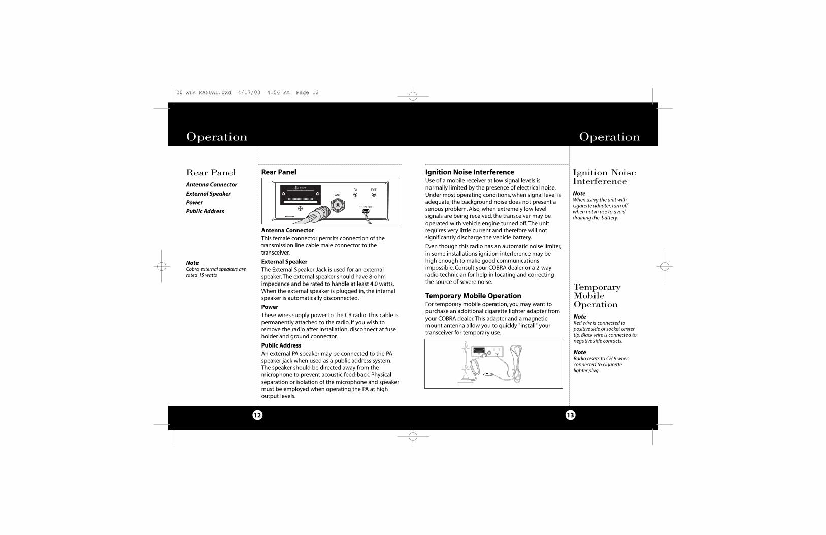
Rear Panel
Antenna ConnectorThis female connector permits connection of thetransmission line cable male connector to thetransceiver.
External SpeakerThe External Speaker Jack is used for an externalspeaker. The external speaker should have 8-ohmimpedance and be rated to handle at least 4.0 watts.When the external speaker is plugged in, the internalspeaker is automatically disconnected.
PowerThese wires supply power to the CB radio. This cable ispermanently attached to the radio. If you wish toremove the radio after installation, disconnect at fuseholder and ground connector.
Public AddressAn external PA speaker may be connected to the PAspeaker jack when used as a public address system.The speaker should be directed away from themicrophone to prevent acoustic feed-back. Physicalseparation or isolation of the microphone and speakermust be employed when operating the PA at highoutput levels.
Rear PanelAntenna Connector
External Speaker
Power
Public Address
Operation
NoteCobra external speakers arerated 15 watts
EXT
ANT
13.8V DC
PA
20 XTR MANUAL.qxd 4/17/03 4:56 PM Page 12
15
Maintenance/Adjustment
Maintenance
Maintenance and AdjustmentYour COBRA CB transceiver is specifically designed forthe environment encountered in mobile installations.The use of all solid state circuitry and its light weightresult in high reliability. Should a failure occur,however, review the following, then if necessary,replace parts only with identical parts. Do notsubstitute.
� Check connections to the source of power andmake sure it is the 13.8 VDC required to operateyour radio.
� Check the fuses in the DC power cord. The mainpower lead (red ) has a 2 amp 3AG type fuse in itsholder. Use only the above specified type and sizefuse for maximum protection. Failure to do so willvoid the warranty.
� Make certain the microphone is properlyplugged in.
� Make certain the antenna is properly assembledand connected.
If you are unable to correct the problem, refer to theSERVICE INSTRUCTIONS at the end of this manual forthe correct procedure for warranty and post-warrantyservice from COBRA.
14
Operating Procedure to Receive� Be sure that power cord, antenna and microphone
are connected to the proper connectors beforeproceeding further. The CB/PA switch should be inthe "CB" position.
� Turn the radio ON by rotating the VOLUMECONTROL clockwise.
� Rotate SQUELCH CONTROL counterclockwise untilincoming signal is heard.
� Select the desired channel.
� Set VOLUME CONTROL to a comfortable listeninglevel.
Operating Procedure to Transmit� Select the desired channel.
� The receiver and transmitter are controlled by thepress-to-talk switch on the microphone. Press theswitch and the transmitter is activated; releaseswitch to receive. When transmitting (on a clearchannel), hold the microphone two inches from themouth and speak clearly in a normal voice.
Be sure the antenna is properly connected to theradio before transmitting. Prolonged transmittingwithout an antenna, or a poorly matched antenna,could cause damage to the transmitter.
Operation
OperatingProcedure to Receive
OperatingProcedure to Transmit
20 XTR MANUAL.qxd 4/17/03 4:56 PM Page 14
CB DistressData
17
CB Distress Data
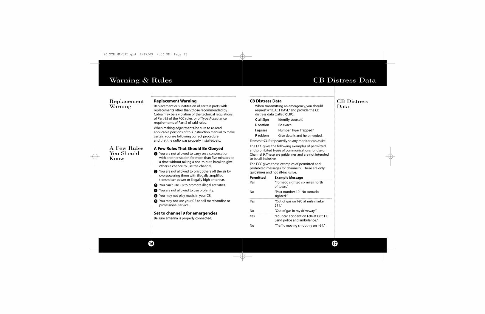
CB Distress DataWhen transmitting an emergency, you shouldrequest a “REACT BASE” and provide the CBdistress data (called CLIP):
C all Sign Identify yourself.
L ocation Be exact.
I njuries Number. Type. Trapped?
P roblem Give details and help needed.
Transmit CLIP repeatedly so any monitor can assist.
The FCC gives the following examples of permittedand prohibited types of communications for use onChannel 9. These are guidelines and are not intendedto be all-inclusive.
The FCC gives these examples of permitted andprohibited messages for channel 9. These are onlyguidelines and not all-inclusive:
Permitted Example MessageYes “Tornado sighted six miles north
of town.”
No “Post number 10. No tornadosighted.”
Yes “Out of gas on I-95 at mile marker211.”
No “Out of gas in my driveway.”
Yes “Four car accident on I-94 at Exit 11.Send police and ambulance.”
No “Traffic moving smoothly on I-94.”
Warning & Rules
16
A Few RulesYou ShouldKnow
Replacement WarningReplacement or substitution of certain parts with replacements other than those recommended byCobra may be a violation of the technical regulationsof Part 95 of the FCC rules, or of Type Acceptancerequirements of Part 2 of said rules.
When making adjustments, be sure to re-readapplicable portions of this instruction manual to makecertain you are following correct procedure and that the radio was properly installed, etc.
A Few Rules That Should Be Obeyed� You are not allowed to carry on a conversation
with another station for more than five minutes ata time without taking a one-minute break to giveothers a chance to use the channel.
� You are not allowed to blast others off the air byoverpowering them with illegally amplifiedtransmitter power or illegally high antennas.
� You can't use CB to promote illegal activities.
� You are not allowed to use profanity.
� You may not play music in your CB.
� You may not use your CB to sell merchandise orprofessional service.
Set to channel 9 for emergenciesBe sure antenna is properly connected.
ReplacementWarning
20 XTR MANUAL.qxd 4/17/03 4:56 PM Page 16
19
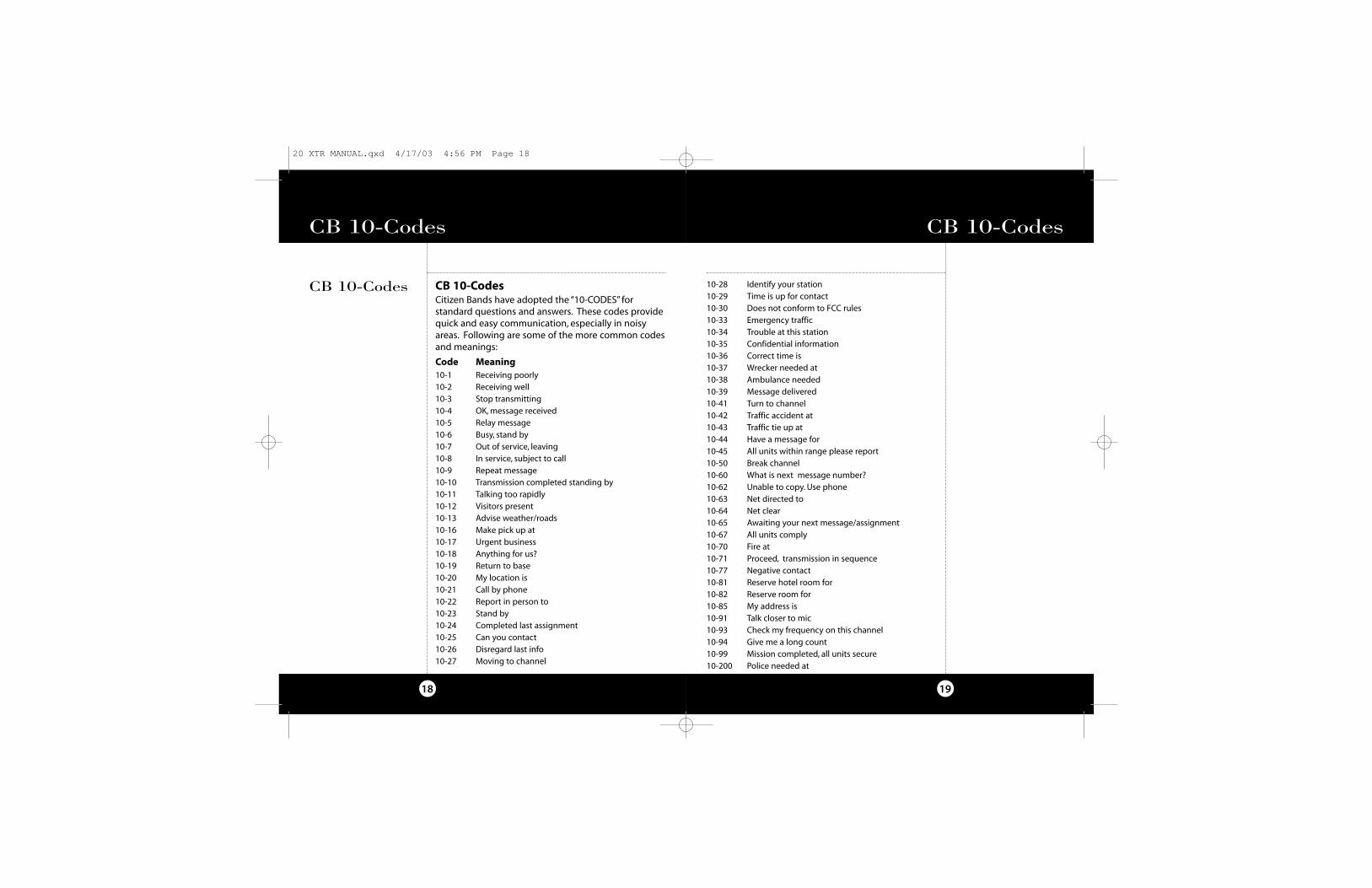
10-28 Identify your station10-29 Time is up for contact10-30 Does not conform to FCC rules10-33 Emergency traffic 10-34 Trouble at this station10-35 Confidential information10-36 Correct time is10-37 Wrecker needed at10-38 Ambulance needed10-39 Message delivered10-41 Turn to channel10-42 Traffic accident at10-43 Traffic tie up at10-44 Have a message for10-45 All units within range please report10-50 Break channel10-60 What is next message number?10-62 Unable to copy. Use phone10-63 Net directed to10-64 Net clear10-65 Awaiting your next message/assignment10-67 All units comply10-70 Fire at10-71 Proceed, transmission in sequence10-77 Negative contact10-81 Reserve hotel room for10-82 Reserve room for10-85 My address is10-91 Talk closer to mic10-93 Check my frequency on this channel10-94 Give me a long count10-99 Mission completed, all units secure10-200 Police needed at
CB 10-Codes
18
CB 10-CodesCitizen Bands have adopted the “10-CODES” forstandard questions and answers. These codes providequick and easy communication, especially in noisyareas. Following are some of the more common codesand meanings:
Code Meaning10-1 Receiving poorly10-2 Receiving well10-3 Stop transmitting10-4 OK, message received10-5 Relay message10-6 Busy, stand by10-7 Out of service, leaving10-8 In service, subject to call10-9 Repeat message10-10 Transmission completed standing by10-11 Talking too rapidly10-12 Visitors present10-13 Advise weather/roads 10-16 Make pick up at10-17 Urgent business10-18 Anything for us?10-19 Return to base10-20 My location is10-21 Call by phone10-22 Report in person to10-23 Stand by10-24 Completed last assignment10-25 Can you contact10-26 Disregard last info10-27 Moving to channel
CB 10-Codes
CB 10-Codes
20 XTR MANUAL.qxd 4/17/03 4:56 PM Page 18
21
Specifications
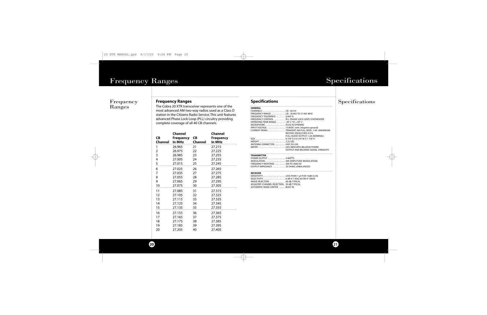
GENERALCHANNELS . . . . . . . . . . . . . . . . . . . . . . . CB - 40 CH FREQUENCY RANGE. . . . . . . . . . . . . . . CB - 26.965 TO 27.405 MHZFREQUENCY TOLERANCE. . . . . . . . . . 0.005 %FREQUENCY CONTROL . . . . . . . . . . . PLL (PHASE LOCK LOOP) SYNTHESIZEROPERATING TEMP. RANGE . . . . . . . . . -30° C TO + 65° CMICROPHONE . . . . . . . . . . . . . . . . . . . . PLUG-IN DYNAMICINPUT VOLTAGE . . . . . . . . . . . . . . . . . . 13.8VDC nom. (negative ground) CURRENT DRAIN . . . . . . . . . . . . . . . . . . TRANSMIT: AM FULL MOD., 1.4A (MAXIMUM)
RECEIVE: SQUELCHED, 0.9 A;FULL AUDIO OUTPUT, 1.2A (NOMINAL)
SIZE . . . . . . . . . . . . . . . . . . . . . . . . . . . . . . 6-7/8” D X 6-3/4”W X 1-7/8” HWEIGHT . . . . . . . . . . . . . . . . . . . . . . . . . . 3.25 LBS.ANTENNA CONNECTOR . . . . . . . . . . . UHF; SO-239METER. . . . . . . . . . . . . . . . . . . . . . . . . . . . LED; INDICATES RELATIVE POWER
OUTPUT AND RECEIVED SIGNAL STRENGTH
TRANSMITTERPOWER OUTPUT . . . . . . . . . . . . . . . . . . 4 WATTSMODULATION . . . . . . . . . . . . . . . . . . . . AM (AMPLITUDE MODULATION)FREQUENCY RESPONSE . . . . . . . . . . . 300 TO 3000 HZOUTPUT IMPEDANCE . . . . . . . . . . . . . 50 OHMS, UNBALANCED
RECEIVERSENSITIVITY. . . . . . . . . . . . . . . . . . . . . . . LESS THAN 1 µV FOR 10dB (S+N) SELECTIVITY . . . . . . . . . . . . . . . . . . . . . . 6 dB @ 7 KHZ, 60 DB @ 10KHZIMAGE REJECTION . . . . . . . . . . . . . . . . 60 dB, TYPICALADJACENT-CHANNEL REJECTION. . 50 dB, TYPICALAUTOMATIC NOISE LIMITER . . . . . . . BUILT-IN
Specifications
20
FrequencyRanges
Frequency Ranges
Frequency RangesThe Cobra 20 XTR transceiver represents one of themost advanced AM two-way radios used as a Class Dstation in the Citizens Radio Service. This unit featuresadvanced Phase Lock Loop (PLL) circuitry providingcomplete coverage of all 40 CB channels.
Channel ChannelCB Frequency CB FrequencyChannel In MHz Channel In MHz1 26.965 21 27.2152 26.975 22 27.2253 26.985 23 27.2554 27.005 24 27.2355 27.015 25 27.245
6 27.025 26 27.2657 27.035 27 27.2758 27.055 28 27.2859 27.065 29 27.29510 27.075 30 27.305
11 27.085 31 27.31512 27.105 32 27.32513 27.115 33 27.33514 27.125 34 27.34515 27.135 35 27.355
16 27.155 36 27.36517 27.165 37 27.37518 27.175 38 27.38519 27.185 39 27.39520 27.205 40 27.405
Specifications
20 XTR MANUAL.qxd 4/17/03 4:56 PM Page 20
23
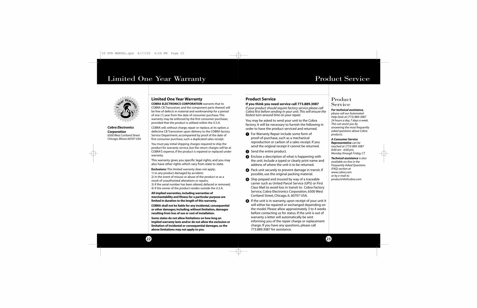
Product ServiceIf you think you need service call 773.889.3087If your product should require factory service please callCobra first before sending in your unit. This will ensure thefastest turn-around time on your repair.
You may be asked to send your unit to the Cobrafactory. It will be necessary to furnish the following inorder to have the product serviced and returned.
� For Warranty Repair include some form of proof-of-purchase, such as a mechanicalreproduction or carbon of a sales receipt. If yousend the original receipt it cannot be returned.
� Send the entire product.
� Enclose a description of what is happening withthe unit. Include a typed or clearly print name andaddress of where the unit is to be returned.
� Pack unit securely to prevent damage in transit. Ifpossible, use the original packing material.
� Ship prepaid and insured by way of a traceablecarrier such as United Parcel Service (UPS) or FirstClass Mail to avoid loss in transit to: Cobra FactoryService, Cobra Electronics Corporation, 6500 WestCortland Street, Chicago, IL 60707 USA.
� If the unit is in warranty, upon receipt of your unit itwill either be repaired or exchanged depending onthe model. Please allow approximately 3 to 4 weeksbefore contacting us for status. If the unit is out ofwarranty a letter will automatically be sentinforming you of the repair charge or replacementcharge. If you have any questions, please call773.889.3087 for assistance.
ProductServiceFor technical assistance,please call our AutomatedHelp Desk at (773) 889-308724 hours a day, 7 days a week.This can assist you byanswering the most frequentlyasked questions about Cobraproducts.
A Consumer ServiceRepresentative can bereached at (773) 889-3087 8:00 am - 6:00 pm,Monday through Friday, CT.
Technical assistance is alsoavailable on-line in theFrequently Asked Questions(FAQ) section atwww.cobra.com or by e-mail [email protected]
Product Service
22
Limited One Year WarrantyCOBRA ELECTRONICS CORPORATION warrants that itsCOBRA CB Transceiver, and the component parts thereof, willbe free of defects in material and workmanship for a periodof one (1) year from the date of consumer purchase. Thiswarranty may be enforced by the first consumer purchaser,provided that the product is utilized within the U.S.A.
COBRA will, without charge, repair or replace, at its option, adefective CB Transceiver upon delivery to the COBRA factoryService Department, accompanied by proof of the date offirst consumer purchase, such a duplicated sales receipt.
You must pay initial shipping charges required to ship theproduct for warranty service, but the return charges will be atCOBRA’S expense, if the product is repaired or replaced underwarranty.
This warranty gives you specific legal rights, and you mayalso have other rights which vary from state to state.
Exclusions: This limited warranty does not apply;1) to any product damaged by accident;2) in the event of misuse or abuse of the product or as aresult of unauthorized alterations or repairs;3) if the serial number has been altered, defaced or removed;4) if the owner of the product resides outside the U.S.A.
All implied warranties, including warranties ofmerchantability and fitness for a particular purpose arelimited in duration to the length of this warranty.
COBRA shall not be liable for any incidental, consequentialor other damages; including, without limitation, damagesresulting from loss of use or cost of installation.
Some states do not allow limitations on how long animplied warranty lasts and/or do not allow the exclusion orlimitation of incidental or consequential damages, so theabove limitations may not apply to you.
Cobra ElectronicsCorporation6500 West Cortland StreetChicago, Illinois 60707 USA
Limited One Year Warranty
1Ye
ar Warranty
20 XTR MANUAL.qxd 4/17/03 4:56 PM Page 22
24
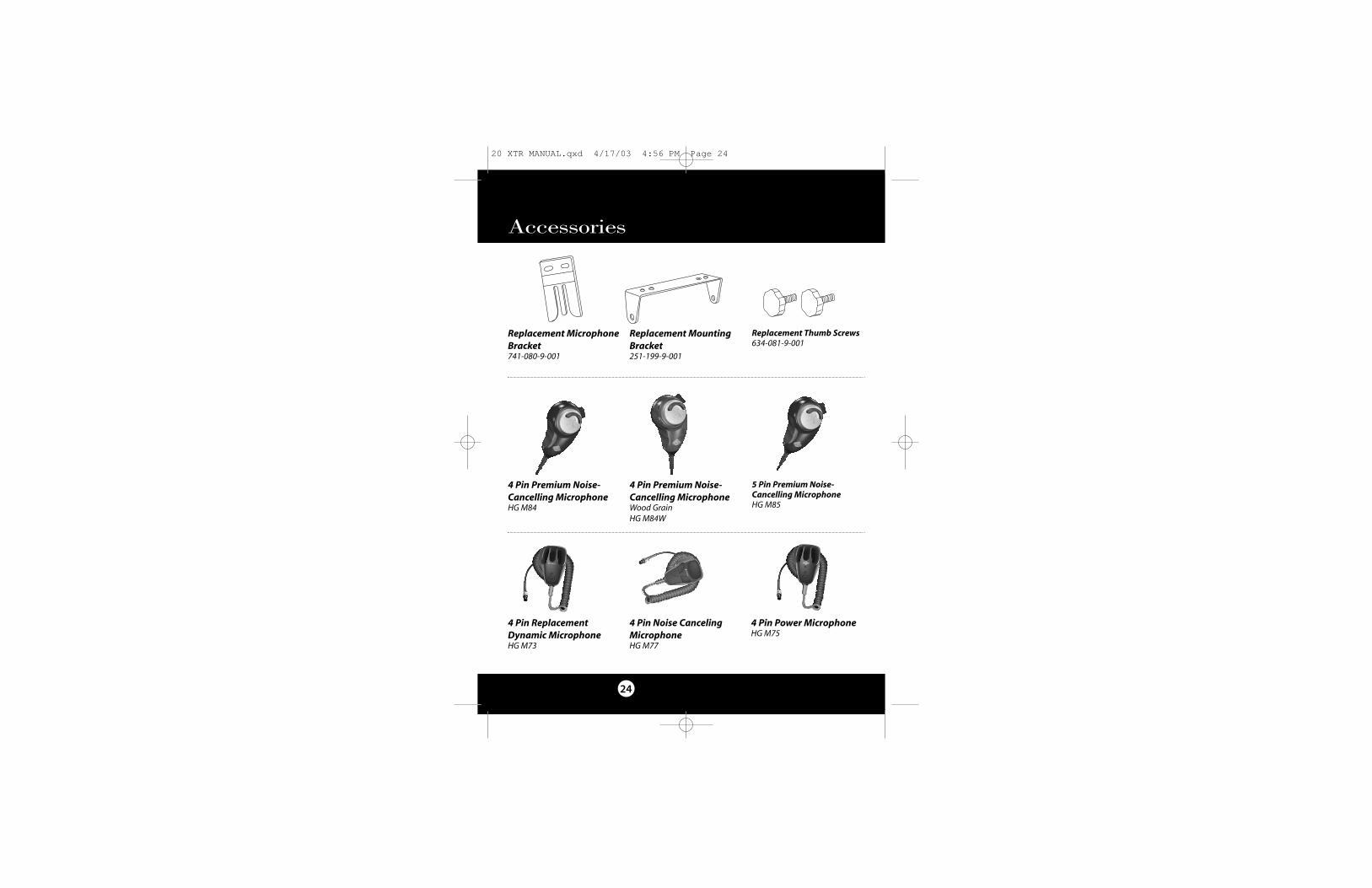
Accessories
Replacement MountingBracket251-199-9-001
Replacement Thumb Screws634-081-9-001
Replacement MicrophoneBracket741-080-9-001
4 Pin Power Microphone HG M75
4 Pin Noise CancelingMicrophoneHG M77
4 Pin ReplacementDynamic MicrophoneHG M73
4 Pin Premium Noise-Cancelling MicrophoneHG M84
4 Pin Premium Noise-Cancelling MicrophoneWood GrainHG M84W
5 Pin Premium Noise-Cancelling MicrophoneHG M85
20 XTR MANUAL.qxd 4/17/03 4:56 PM Page 24