2.0 alternatives considered
TRANSCRIPT

Mid-City/Exposition LRT Project 2.0 Alternatives ConsideredFinal EIS/EIR
2-1taha 2005-020
2.0 ALTERNATIVES CONSIDERED
This chapter describes the alternatives that are evaluated in this Final EIS/EIR for the Los Angeles Mid-City/Exposition Corridor. Two basic alternatives are reviewed: 1) the No Build Alternative, and 2) theLRT Build Alternative selected as the Locally Preferred Alternative (LPA).
Following public review of the alternatives contained in the Mid-City/Westside Transit Corridor DraftEIS/EIR in June 2001, the Metro Board of Directors adopted a Locally Preferred Alternative (DraftEIS/EIR Alternative #3a) which included a Bus Rapid Transit (BRT) project on Wilshire Boulevard anda Light Rail Transit (LRT) project along the Exposition Right-of-Way from Downtown Los Angeles toCulver City. The Mid-City/Westside Study Area was separated into two separate corridors for thepurposes of final environmental clearance; the Mid-City/Wilshire Corridor and the Mid-City/ExpositionCorridor. The Mid-City/Wilshire Bus Rapid Transit Project Final EIR was certified by the Metro Boardof Directors in August 2002. The Mid-City/Exposition Corridor LRT Build Alternative is the subject ofthis Final EIS/EIR.
Since the completion of the Draft EIS/EIR, Metro has decided to modify some portions of the Mid-City/Exposition LRT Build Alternative. Metro has added two Downtown Los Angeles alignment options(Flower Street and Hill Street Couplet) in response to comments from the City of Los Angeles regardingthe proposed LRT Build Alternative traffic impacts along Washington Boulevard. Metro has removedthe “Non-Revenue Connector” track and mid-day rail storage yard south of Downtown Los Angeles inresponse to community concerns that were revealed during circulation of the Draft EIS/EIR and replacedthese facilities with expansion of the existing Metro Blue Line Yard in Carson. A grade-separation at LaBrea Station and two alternatives for grade-separation of La Cienega and Jefferson Boulevards were addedto the Project description in response to Metro’s Grade Crossing Policy and traffic and safety concernsexpressed by the Cities of Los Angeles and Culver City. In addition, Metro introduced two alternate sitesfor the parking structure at the La Cienega station. Lastly, three design options for the Venice/Robertsonstation were also added to the Project description to address LADOT and Culver City concerns about theoperation of the Washington/National Boulevards intersection with LRT.
This chapter provides a background of planning studies leading to the selection of the LRT BuildAlternative and provides a detailed description of the No Build and LRT Build Alternatives that areevaluated in Chapters 3.0 Transportation Impacts and Mitigation and 4.0 Affected Environment andEnvironmental Consequences of this document.

Mid-City/Exposition LRT Project 2.1 Background & Planning ContextFinal EIS/EIR
2.1-1taha 2005-020
2.1 BACKGROUND AND PLANNING CONTEXT
2.1.1 ORIGINAL METRO RED LINE STUDIES (1983-1988)
The Metro Red Line Mid-City/Westside Extension has been an integral element of local, regional andfederal transportation planning since the early 1980s. Extending westward from the Los Angeles CentralBusiness District (LACBD) to the Mid-City areas of the Fairfax District or Pico/San Vicente, the Mid-City/Westside Extension had been the subject of in-depth technical studies and extensive communityinvolvement during this period. Ultimately, the line has been envisioned to extend to Century City,Westwood (UCLA) and West Los Angeles.
In 1983, the original Locally Preferred Alternative for the extension of the Metro Red Line (Figure 2.1-1)identified an alignment that followed Wilshire Boulevard to Fairfax Avenue and then north to Hollywoodand the San Fernando Valley. In 1985, a naturally-occurring methane gas caused a fire at a Ross “Dressfor Less” store, located along the selected LPA alignment, resulted in an investigation by a special Cityof Los Angeles Task Force. Conclusions from this investigation lead to a Congressional prohibition onfederal funding for subway construction within the designated Methane Gas Risk Zone, as determinedby the 1985 Task Force report on subsurface conditions in the region. As mandated by the Congressionalprohibition, a Congressionally Ordered Re-Engineering (CORE) study was conducted. The intent of thisstudy was to determine an appropriate alignment through which to link the Los Angeles CentralBusiness District, the San Fernando Valley and the Westside. Over 40 candidate alignments werereviewed and six alignments where studied in detail in environmental reports.
In July 1988, a new LPA was chosen. This new LPA would travel from Downtown Los Angeles UnionStation to Wilshire/Vermont and split into two separate lines, one traveling west to Wilshire/Westernand the other proceeding north to Hollywood and North Hollywood. This alignment was subsequentlyapproved for construction and completed as a series of projects. The subway was completed from UnionStation to Westlake/MacArthur Park in 1993, to Wilshire/Western Station in 1996, to Hollywood/Vinein 1999 and to North Hollywood in 2000.
2.1.2 EARLY SYSTEMS PLANNING STUDIES (1989-1990)
In order to evaluate the feasibility of further rapid transit extensions to the Metro Red Line, twoimportant studies were conducted to provide the systemwide framework for such expansion, the MetroRed Line Extension System Planning Study was prepared by the Southern California Association ofGovernments (SCAG) in 1989 (Figure 2.1-2). In addition, the Los Angeles Metro Orange Line Extension:Transitional Analysis was prepared by the Los Angeles County Transportation Commission (LACTC)in 1990. (The Los Angeles County Metropolitan Transit Authority (Metro) is the successor agency to boththe LACTC and the Southern California Rapid Transit District (SCRTD). ) These reports document thehistorical framework for the definition of the Mid-City/Westside Transit Corridor, as well as othercorridors. They provide the background systems analysis that was used to justify the need for majorcapital expenditures in these corridors. The results of the two studies are summarized in the followingsections.
The August 1989 Metro Red Line Extension System Planning Study was prepared by SCAG for theLACTC to evaluate future extensions of the original 18-mile Metro Red Line subway line between UnionStation and North Hollywood. The Extension Study evaluated travel corridor characteristics, reviewedexisting transit operations and analyzed the proposed corridor for consistency with the adopted regionalplan. Based on the analysis, the study identified proposed corridor extensions, which met federal criteriafor ridership, projected transit demand and which was consistent with the adopted regional plan.

105
405
10
5
90110
101
FIGURE 2.1-1METRO ORIGINAL LOCALLY
PREFERRED ALTERNATIVE-1983
MID-CITY/EXPOSITION LRT PROJECT FINAL EIS/EIRLOS ANGELES COUNTY METROPOLITAN TRANSPORTATION AUTHORITY
LEGEND:
Existing Red Line
Existing Blue Line
Existing Green Line
Metro Red Line 1983 LPA
SUNSET BLVD
SANTA
MO
NIC
ABLV
D
WIL
SHIR
EBLV
D
VEN
ICE
BLV
D
WILSHIRE BLVD
MANCHESTER BLVD
LINC
OLN
BLVD
EL SEGUNDO BLVD
CENTURY BLVD
FLORENCE AVE
VERNON AVE
SLAUSON AVE
LUTHER KING JR BLVD
EXPOSITION BLVD
WASHINGTON BLVD
OLYMPIC BLVD
BEVERLY BLVD
HOLLYWOOD BLVD
JEFFERSON BLVD
MAR
TIN
CE
NT
RA
LA
VE
FIG
UE
RO
AA
VE
VE
RM
ON
TA
VE
WE
ST
ER
NA
VE
CR
EN
SH
AW
BLV
D
SE
PU
LV
ED
AB
LV
D
LA
CIE
NE
GA
BLV
D
LA
BR
EA
AV
E
CU
LV
ER
BLV
D
RO
BE
RT
SO
NB
LV
D
FLO
WER
ST
HIG
HLA
ND
AV
E
HO
OV
ER
ST
SOURCE: Mid-City/Westside Transit Corridor Study, Re-Evaluation/Major Investment Study Report, 2000
NORTH
FA
IRFA
XA
VE

MID-CITY/EXPOSITION LRT PROJECT FINAL EIS/EIRLOS ANGELES COUNTY METROPOLITAN TRANSPORTATION AUTHORITY FIGURE 2.1-2
SCAG METRO RED LINE EXTENSIONSYSTEM PLANNING STUDY (1989)
LEGEND:
SOURCE: Southern California Association of Governments (SCAG)
NORTH
METHANE AREA
METHANE AREA

Mid-City/Exposition LRT Project 2.1 Background & Planning ContextFinal EIS/EIR
2.1-4taha 2005-020
Based on the 1989 System Planning Study, a Central East/West Corridor was identified as the highestpriority for a Metro Red Line LPA heavy rail extension. The 1990 Transitional Analysis was undertakento demonstrate that an extension to the east and west could meet federal cost-effectiveness thresholdsand provide the basis for proceeding with an Alternatives Analysis/Draft Environmental ImpactStatement (AA/Draft EIS). Based on conservative assumptions for the ridership projections, the totalcost per new rider was determined to be under the federal threshold. This supported the decision toproceed with a full AA/Draft EIS for the east-west corridor extensions.
2.1.3 METRO RED LINE MID-CITY EXTENSION STUDIES (1990-1998)
In 1990, approval of Proposition C created a new local funding source for transit projects. In 1992 afurther study of a Metro Red Line extension to the west was conducted. The 1992 Final SupplementalEnvironmental Impact Statement/Final Supplemental Environmental Impact Report (Final SEIS/SEIR)adopted an LPA for the Mid-City segment showing the construction of a Metro Red Line extension fromWilshire/Western Station to Pico/San Vicente Boulevards (Figure 2.1-3).
In 1993, geotechnical tests conducted to provide detailed information concerning the nature and extentof hydrogen sulfide gas along the Mid-City LPA alignment found concentrations much greater thanpreliminary tests had identified. This discovery prompted the 1994 Metro Red Line Segment 3/Mid-CityExtension Reassessment Study which identified possible vertical alternative alignments for the LPA tomitigate impacts from the hydrogen sulfide gas. The conclusions of this study initiated a newSEIS/SEIR in 1996 to assess the environmental impacts of shallow cut-and-cover and aerialconfigurations along the original Crenshaw Boulevard alignment.
The environmental process determined that the impacts of this alignment were highly negative to thecommunity. In an effort to mitigate these impacts, the March 1996 Mid-City Alternative Gas ExplorationStudy was conducted to investigate a deep-bore tunneling option along the Wilton Place/ArlingtonAvenue alignment, approximately one-quarter mile east of the adopted LPA. Results of the geotechnicaltests done along this alignment produced significantly lower hydrogen sulfide levels. As a result, theDraft Supplemental EIS/Supplemental ElR underway for the Mid-City Segment added aWilton/Arlington alignment.
In January 1998, Metro suspended work on extensions of the Metro Red Line heavy rail subway Projectin the Mid-City and Eastside Corridors. The North Hollywood Extension of the Metro Red Line wasallowed to continue into construction. Figure 2.1-3 illustrates the completed Metro Red Line Project withthe suspended segments in the Mid-City and Eastside Corridors.

AV
PA
LA
AL
TA
DEN
AD
R
T
/
/
DOUGLAS
/
MARINE/
GRAND
AV
I
HOLLYWOOD
FIGURE 2.1-3METRO RED LINE EXTENSION
SUSPENDED SEGMENTS (1998)
SOURCE: Los Angeles MetropolitanTransportation Authority
MID-CITY/EXPOSITION LRT PROJECT FINAL EIS/EIRLOS ANGELES COUNTY METROPOLITAN TRANSPORTATION AUTHORITY
�������������� ��������������������������� ���������������������������������� ���������������������������������������� ����������������������� ���������� �!"��#�� �������������
NORTH

Mid-City/Exposition LRT Project 2.1 Background & Planning ContextFinal EIS/EIR
2.1-6taha 2005-020
2.1.4 EARLY PLANNING STUDIES FOR THE EXPOSITION RIGHT-OF-WAY (1992-1994)
Three planning studies were conducted in the early 1990s following the purchase of the Southern PacificExposition railroad right-of-way. These studies envisioned a project that could be locally funded inaddition to the Metro Red Line Mid-City/Westside Extension. These studies were suspended in 1994 dueto lack of funding.
The Exposition Right-of-Way Preliminary Planning Study was completed in May 1992. This studyevaluated alternatives for the 12-mile corridor of the former Southern Pacific Railroad right-of-wayextending from just south of Downtown Los Angeles to 17th Street in Santa Monica. The study examinedlight rail transit, trolley bus, a transitway, and a bicycle path. The study recommended four routes andvarious types of modes for these routes for further study, and identified steps on which subsequentstudies should focus on.
The Exposition Right-of-Way Final Draft Phase I Summary Report was completed in December 1994.This study continued the transportation planning process initiated in the May 1992 Preliminary PlanningStudy and examines transit improvements to address mobility needs and demands in the ExpositionRight-of-Way Corridor. The study recommended to defer or retain alternatives developed in the courseof the analysis and recommended design enhancements and light rail transit (LRT) enhancementoptions.
The Exposition Park Branch Line Rail Transit Corridor Route EIR was completed in April 1992. Thisenvironmental impact report examined light rail transit facilities which would operate as a branch ofMetro Blue Line. The extensions would link and serve the employment, residential, educational, andcultural centers in Downtown Los Angeles to Exposition Park, USC Campus area and Vermont Avenuebusiness area.
The proposed Exposition Park Branch Line is an LRT line, which would extend along Flower Street fromthe junction with the existing Blue Line at Washington Boulevard to the Exposition Boulevard right-of-way to a terminus at Vermont Avenue. This Project was environmentally cleared in 1992.
2.1.5 METRO RAPID AND OTHER BUS SERVICE IMPROVEMENT STUDIES (1998-2002)
A number of important bus transit studies were conducted during the time that fixed guideway studieswere underway. These studies developed the Metro Rapid bus transit system that serves as an extensionof the fixed guideway system. Metro Rapid bus is Metro’s identification or “branding” for Bus RapidTransit (BRT), which contains several or all BRT attributes, from non-fixed guideway to fixed guidewayMetro Rapid bus as listed in the following studies.
The Westside Bus Improvement Study was completed in March 1998 and examined bus improvementsin the area bounded by Hoover/Hyperion, the Pacific Ocean/Malibu, Mulholland Drive, and 1-10Freeway/Culver City southern boundary/Jefferson Boulevard. The study found that the current busservice resulted in: slow arterial bus operations, overcrowding on certain lines/times, bus bunching, andcontinuity and coordination problems. Recommendations included introducing new and faster “MetroRapid” bus-service and high capacity buses; adjusting network and services for the Metro Red Lineopenings; improving network connections and service continuity; restructuring duplicated or poorlyperforming bus route segments; enhancing bus passenger facilities; and developing a “seamless” farestructure.
The Mid-Cities Bus Transit Restructuring Study was completed in March 1999 as a follow-up to theearlier 1993 Inner City Transit Needs Assessment Study, with the goals of improving ridership,operations, cost efficiency and cost effectiveness, and integration of the transit system. The Study Area

Mid-City/Exposition LRT Project 2.1 Background & Planning ContextFinal EIS/EIR
2.1-7taha 2005-020
was bounded by the I-105 Freeway, the Pacific Ocean/La Cienega Boulevard, Slauson Avenue/MarinaFreeway, and Alameda Street. Recommendations from the study included a three-tiered restructuringstrategy that addressed the needs of the core service of basic routes, the community connectors whichserve inter-community travel, and the local services, including shuttles, circulators, feeder services, anddemand responsive services.
The Los Angeles Metro Rapid Bus Demonstration Program was initiated in March 1999 by Metro*sBoard of Directors following an initial feasibility study. Staff was directed by the Board to conduct thefeasibility study in response to a visit to Curitiba, Brazil by Metro and City of Los Angeles officials. TheCuritiba urban design and public transportation model has been widely praised internationally for itssuccess and has been a major force in the Federal Transit Administration creation of a national BusRapid Transit (BRT) initiative. The feasibility study recommended that Metro, in partnership with theCity of Los Angeles, conduct a demonstration along two-to-three major arterials which have strongridership and unique characteristics to provide broad actual experience regarding the feasibility of full-scale deployment of BRT within the Metro system. However, of the 13 key attributes associated with thesuccessful Curitiba BRT, only seven were deemed feasible for implementation during the Phase IDemonstration Program. The remaining six attributes would be deployed in Phase II, system expansion,if the initial demonstration proved successful.
Phase I demonstration implementation planning was initiated in the summer of 1999 with a Spring 2000goal for start-up of Metro Rapid Bus. Two lines were selected for the demonstration:
• Line 720 Wilshire/Whittier (very high passenger demand urban corridor connecting through theLos Angeles Central Business District (LACBD)
• Line 750 Ventura (high passenger demand suburban corridor serving the Metro Red Line)
The two Metro Rapid lines were implemented on June 24, 2000, coinciding with the opening of theextension of the Metro Red Line to the San Fernando Valley. All seven of the Phase I attributes werefully operational at start-up with the exception of the Metro Rapid Stations where temporary stops wereutilized.
The Metro Rapid Expansion Program Phase 11 was adopted by Metro Board of Directors in February2002. Based on the demonstrated success of Metro Rapid initial lines on Wilshire and VenturaBoulevards, expansion of the system was proposed to the Metro Board of Directors in February 2002.The expansion program identified 28 corridors which best met the Metro Rapid program goals andobjectives, and recommended a phasing plan designed to construct a network of Metro Rapid service.This network was adopted as a part of the Metro Short Range Transportation Plan for fullimplementation by the year 2008 (Figure 2.1-4).

MID-CITY/EXPOSITION LRT PROJECT FINAL EIS/EIRLOS ANGELES COUNTY METROPOLITAN TRANSPORTATION AUTHORITY FIGURE 2.1-4
METRO RAPID PROGRAM APPROVED SYSTEM MAP (2002)
SOURCE: Metro Countywide Planning & Development, June 2004
NORTH

Mid-City/Exposition LRT Project 2.2 Re-Evaluation StudiesFinal EIS/EIR
2.2-1taha 2005-020
2.2 RE-EVALUATION STUDIES FOR MID-CITY/WESTSIDE TRANSIT IMPROVEMENTS(1998-2000)
In January 1998, Metro suspended work on extensions of the Metro Red Line heavy rail subway Project,which included the initial 2.3-mile segment of the Mid-City Locally Preferred Alternative (LPA) fromWilshire/Western to Pico/San Vicente. This action to suspend further Metro Red Line subwayextensions created the need for reevaluation of overall system planning for the affected corridor so thatalternative plans for transit service could be developed. As a result, several planning initiatives wereundertaken between 1998 and 2000 to redirect the planning of transit projects. These studies andinitiatives are described below.
2.2.1 Metro Restructuring Plan
The Metro Restructuring Plan titled: Analysis and Documentation of Metro’s Financial and ManagerialAbility to Complete North Hollywood Rail Construction and Meet the Terms of the Bus Consent Decree,was adopted by the Metro Board of Directors on May 13, 1998 and was subsequently approved by theFTA on July 2, 1998. The Restructuring Plan documented that Metro did not have sufficient localmatching funds to finance heavy rail subway projects in the Eastside Corridor as anticipated in theoriginal Full Funding Grant Agreements for the Project. At the same time, the Restructuring Plan calledfor Metro to study “viable and effective options” for transit in all parts of Los Angeles County, with anemphasis on the corridors in which the rail lines had been suspended.
Within the Mid-City/Westside Corridor, this necessitated the examination of alternative fixed guidewayoptions to heavy rail subway. It also committed Metro to a reevaluation of the financial capacities of theagency to undertake new start, fixed guideway projects. To that end, the Board authorized the RegionalTransit Alternatives Analysis (RTAA) Study that commenced in July 1998 and was completed inNovember 1998.
2.2.2 SCAG West Los Angeles Transit Corridor Technical Report (August 1998)
Additional information on Corridor transit needs was developed in the West Los Angeles TransitCorridor Technical Report: 1998 RTP Transit Restructuring for Use in the MTA Re-Evaluation Study.This study considered alternatives to heavy rail subway extensions to the Westside and developed threeconceptual alternatives for different types of transit service. The alternatives identified included:
• Transit Corridors Concept• Intermodal Linkage Concept• Centers Access Concept
Integral to the above concepts was the idea that no single corridor could adequately service a study aslarge as the Westside (Figure 2.2-1). Therefore, all of the concepts endeavored to provide a systemscontext for transit service centered on major corridors and major activity centers. The Transit CorridorsConcept further proposed that the Wilshire Boulevard Transit Corridor be supplemented with a secondcorridor along Exposition and Martin Luther King Boulevards utilizing above-ground transit alternatives.Because of the high cost of subway construction, the alternatives sought to define lower-cost surfacesolutions that could be implemented incrementally over time in order to provide improved transit serviceto larger areas of the Westside more quickly than would be the case with more expensive subwayextension solutions.

FIGURE 2.2-1SCAG WEST LOS ANGELES
RESTRUCTURING ALTERNATIVES (1998)
MID-CITY/EXPOSITION LRT PROJECT FINAL EIS/EIRLOS ANGELES COUNTY METROPOLITAN TRANSPORTATION AUTHORITY
SOURCE: Southern California Association of Governments (SCAG)
NORTH
Proposed Transit Corridors
Future Metro Rail (N. Hollywood)
Existing Metro Rail
Existing Long Beach Blue Line
Transit Stop
Conceptual Routes for Centers Connection
Activity Centers
Future Metro Rail (N. Hollywood)
Existing Metro Rail
Existing Long Beach Blue Line
Conceptual Surface Transit Routes
Express Bus Routes
Inter Modal Connection
Future Metro Rail (N. Hollywood)
Existing Metro Rail
Existing Long Beach Blue Line

Mid-City/Exposition LRT Project 2.2 Re-Evaluation StudiesFinal EIS/EIR
2.2-3taha 2005-020
2.2.3 Regional Transit Alternatives Analysis (November 1998)
The Regional Transit Alternatives Analysis (RTAA) Study accomplished several important objectives forMetro. The study evaluated local funding shortfalls and identified the amount of funding available fornew projects between FY1999 and FY2004. It suggested possible funding allocations, identifiedimmediate bus transit improvements in Los Angeles County, and established a framework for furtherfixed guideway project development in the Eastside, Westside, and San Fernando Valley corridors.
The study included a preliminary evaluation of fixed guideway alternatives in the three corridors. Thestudy did not make recommendations with regard to preferred fixed guideway transit modes orconfigurations, but recommended that a Major Investment Study (MIS) level of analysis be conductedto provide more information regarding these choices.
Results of the RTAA Study were presented to the Metro Board of Directors on November 9, 1998. At thatmeeting, the Board approved the concept of a recommended rapid bus system serving the Eastside,Westside and San Fernando Valley. The Board also reaffirmed its commitment to fund fixed guidewaytransit improvements beyond rapid bus in the suspended rail corridors. A priority funding commitmentof $220 million through FY2004 was made to the Eastside and Mid-City areas from remaininguncommitted funds.
2.2.4 Proposition A Ballot Initiative (Subway Funding Prohibition)
A 1998 ballot initiative referred to as the Metropolitan Transportation Authority Reform andAccountability Act, was approved (and became effective) on November 3, 1998. The most significantprovision of the new law stipulates that no local Proposition A or C sales tax monies shall be used to fundthe planning, design, construction, or operation of any “new subway”. The term “new subway” is definedto mean any subway project (a rail line which is in a tunnel below grade) other than the Metro Red LineSegments 1,2 or 3 (North Hollywood). As a result, the initiative prohibits the use of these sales taxrevenues to build subway extensions in the Mid-City/Westside Corridor.
The initiative does not prohibit the use of sales tax revenues to design and construct light rail, at-graderail, elevated rail systems, or busways in the Mid-City/Westside, or in other areas of Los Angeles County.Nor does this initiative prevent Metro from using state or federal revenues, or local revenues other thansales tax, to design and construct new subways in these areas
2.2.5 Mid-City Westside Re-Evaluation/Major Investment Study (1999-2000)
In June 1999, Metro initiated a Re-Evaluation/Major Investment Study (MIS) for the Mid-City/WestsideStudy Area. Metro also authorized parallel Re-Evaluation/Major Investment Studies for the Eastside andSan Fernando Valley corridors.
There were two major objectives for the Mid-City/Westside Re-Evaluation/Major Investment Study: 1)develop predominantly above-ground alternatives to the suspended Metro Red Line subway Project, and2) identify the Study Area*s long-term transportation needs to be addressed in the Metro Long RangeTransportation Plan. The MIS study provided the public and Metro Board of Directors the technicalinformation needed in order to make an informed decision related to selecting an alternative oralternatives that satisfy the needs of the Mid-City/Westside Study Area. The selected alternatives wouldthen be subjected to the next phase of the analysis, which was the preparation of the Draft EnvironmentalImpact Statement/Environmental Impact Report (Draft EIS/EIR).

Mid-City/Exposition LRT Project 2.2 Re-Evaluation StudiesFinal EIS/EIR
2.2-4taha 2005-020
2.2.5.1 MIS Alternatives
The Re-Evaluation/Major Investment Study looked at six build alternatives, as well as a No Build andTransportation System Management (TSM) Alternative within a broadened study area from thatevaluated in the original Metro Red Line Mid-City/Westside Extension studies. The expanded study areafor the Mid-City/Westside Study Area considered alternatives for the entire Westside of Los Angeles asdescribed in the RTAA and SCAG system studies described previously in this chapter.
The six build alternatives assessed in the Re-Evaluation/MIS (Figure 2.2-2) included:
1. Wilshire Bus Rapid Transit2. Exposition Bus Rapid Transit 3. Exposition Light Rail Transit4. Metro Red Line Extension via Pico/San Vicente5. Metro Red Line Extension via Wilshire Boulevard6. Wilshire Aerial Rail Extension
The reader is referred to the Mid-City/Westside Transit Corridor Study, Re-Evaluation/MIS Report(February 24, 2000), incorporated herein by this reference, for additional information about thealternatives studied and the potential environmental impacts.
2.2.5.2 Metro Board Action on MIS Study (February-March 2000)
In February and March 2000, following their review of the findings of the MIS, the MTA Board providedspecific direction on alternatives to be carried forward into the next phase of analysis. The primary focusof the Board was to evaluate an exclusive lane for Bus Rapid Transit along Wilshire Boulevard fromWestern and Wilshire to downtown Santa Monica (MIS Alternative #1). Additionally, the Boardconsidered Bus Rapid Transit and Light Rail Transit in the Metro Exposition Right-of-Way corridor(Alternatives #2 and #3).
While allowing further consideration of Exposition BRT and LRT, the Metro Board was explicit in theirdirection that the Exposition route be considered as a supporting corridor only, such that Expositionwould not supplant Wilshire Boulevard as the primary Westside transit route. Thus, the Exposition BRTand LRT alternatives to be considered in the Draft EIS/EIR document would need to be considered incombination with the Wilshire BRT alternative. The Metro Board further directed that the Expositionroute not use the former railroad right-of-way in the Cheviot Hills/Rancho Park area between VeniceBoulevard and Sepulveda Boulevard, rather use these streets for the BRT and LRT options.
In keeping with the prior study by SCAG, it was acknowledged that at-grade operations of bus rapidtransit or light rail transit could be constructed along two routes at lower cost than a single, heavy railMetro Red Line extension in subway or aerial configuration. Therefore, the Board directed that heavyrail subway and aerial rail alternatives (#4, #5 and #6) be deleted from further consideration due to highcosts, legislative and geotechnical obstacles to subway construction, and perceived visual and propertyimpacts of aerial guideway construction.

FIGURE 2.2-2MID-CITY/WESTSIDE MIS
ALTERNATIVES (2000)
MID-CITY/EXPOSITION LRT PROJECT FINAL EIS/EIRLOS ANGELES COUNTY METROPOLITAN TRANSPORTATION AUTHORITY
WILSHIRE BRTALTERNATIVE 1:
SANTA
MONICA
CULVER CITY
MARINA
DEL REY
DOWNTOWN
LOS ANGELES
BEVERLY
HILLS
PR
AIR
IEA
VE
SE
PU
LV
ED
AB
LV
D
ARBOR VITAE
AIR
PO
RT
BLV
D
SLAUSON AV
VE
RM
ON
TA
V
FIG
UE
RO
AS
T
CR
EN
SH
AW
BLV
D
LA
CIE
NE
GA
CU
LVER
BLV
D
CENTINELA PA
CIF
ICB
LV
D
AL
AM
ED
AS
T
SLAUSON AV
FLORENCE AV
TIJERA
BLV
D
MANCHESTER BLVD FLORENCE
AV
MANCHESTER BLVD
FLORENCE AV
8th
ST
SLAUSON AV
CO
MP
TO
NA
V
NO
RM
AN
DIE
AV
WE
ST
ER
NA
V
AR
LIN
GT
ON
AV
SO
TO
ST
CE
NT
RA
LA
V
DODGER
STADIUM
Hollywood
Park
Hospital
Fox Hills
Mall
Center
Civic
Inglewood
Hall
City
Hollywood
Park
Great
Western
Forum
Vista
Playa
110
90
LUTHER KING JR BLVD
EXPOSITION BLVD
BLV
D
OV
ER
LA
ND
AV
RODEO
PICO
BLVDW
ILSHIR
EBLV
D
SANTA
MO
NIC
ABLV
D
OLYMPIC
BLVD
OLY
MPIC
SAN
VICEN
TE
BLVD
LINCOLN
AV
OV
ER
LA
ND
AV
WILSHIRE BLVD
OLYMPIC BLVD
BEVERLY BLVD
PICO BLVD
OLYMPIC BLVD
VE
RM
ON
TA
V
HO
OV
ER
ST
LINCOLNBLVD
MELROSE AV
SANTA MONICA BLVD
SUNSET BLVD
SANTAM
ONIC
ABLVD
SE
PU
LV
ED
AB
LV
D
VERNON AV
NM
AINST
SPRING
ST
TEMPLESTBEVERLY BLVD
NM
ISSIO
N
BU
ND
YD
R
VENICE
BLVD
PICO
BLVD
RO
BE
RT
SO
NB
LV
D
LA
CIE
NE
GA
BLV
D
FA
IRFA
XA
V
VENICE BLVD
WASHINGTON BLVD
ADAMS BLVD
NO
RM
AN
DIE
AV
WE
ST
ER
NA
V
CR
EN
SH
AW
BLV
D
SA
NTA
FE
AV
ADAMSBLVD
WASHINGTONBLVD
JEFFERSONBLVD
PICOBLVD
9th ST
6thST
3rdST
ALVA
RA
DO
ST
UN
ION
AV
ALVA
RA
DO
ST
FIG
UE
RO
AS
T
WILSHIRE
BLVD
WASHIN
GTON
OCEANPARK
BLVD
BLVD
MO
NTA
NA
AV
WILSHIRE BLVD
3rd ST
JEFFERSON BLVD
SAN VICENTE BLVD
SUN SET
BLV
D
SUNSET
BLV
D
BLVD
RD
MARTIN
STOCKER ST
AL
AM
ED
AS
T
WESTW
OO
DB
LVD
OC
EA
NAV
LA
BR
EA
AV
WIL
TO
NP
L
HIG
HL
AN
DA
V
LA
BR
EA
AV
HOLLYWOOD BLVD
SUNSET
BLV
D
HOLLYWOOD BLVD
CHAVEZ AV
PA
CIF
IC
OC
EA
N
U.C.L.A.
U.S.C.
Regional
Hills
Baldwin
Park
Church
Angeles
Center
Shopping
Midtown
Westwood
Village
Pavillion
Westwood
Park
Regional
CBS
Farmers
Market
Beverly
Center
Cedars
Sinai
Museum
Petersen
LACMA
Tar Pits
La Brea
West
Santa Monica
Municipal
3rd St.
Promenade
Monica
Pier
Santa
Airport
405
10
2
405
5
101
TRANSIT CENTER
SANTA MONICA
Park
Leimert
Baldwin Hills
Crenshaw Plaza
Barbara
Santa
Plaza
10
HOLLYWOOD
HOLLYWOODWEST
SANTA
MONICA
CULVER CITY
MARINA
DEL REY
DOWNTOWN
LOS ANGELES
BEVERLY
HILLS
PR
AIR
IEA
VE
SE
PU
LV
ED
AB
LV
D
ARBOR VITAE
AIR
PO
RT
BLV
D
SLAUSON AV
VE
RM
ON
TA
V
FIG
UE
RO
AS
T
CR
EN
SH
AW
BLV
D
LA
CIE
NE
GA
CU
LVER
BLV
D
CENTINELA PA
CIF
ICB
LV
D
AL
AM
ED
AS
T
SLAUSON AV
FLORENCE AV
TIJERA
BLV
D
MANCHESTER BLVD FLORENCE
AV
MANCHESTER BLVD
FLORENCE AV
8th
ST
SLAUSON AV
CO
MP
TO
NA
V
NO
RM
AN
DIE
AV
WE
ST
ER
NA
V
AR
LIN
GT
ON
AV
SO
TO
ST
CE
NT
RA
LA
V
DODGER
STADIUM
Hollywood
Park
Hospital
Fox Hills
Mall
Center
Civic
Inglewood
Hall
City
Hollywood
Park
Great
Western
Forum
Vista
Playa
110
90
LUTHER KING JR BLVD
EXPOSITION BLVD
BLV
D
OV
ER
LA
ND
AV
RODEO
PICO
BLVDW
ILSHIR
EBLV
D
SANTA
MO
NIC
ABLV
D
OLYMPIC
BLVD
OLY
MPIC
SAN
VICEN
TE
BLVD
LINCOLN
AV
OV
ER
LA
ND
AV
WILSHIRE BLVD
OLYMPIC BLVD
BEVERLY BLVD
PICO BLVD
OLYMPIC BLVD
VE
RM
ON
TA
V
HO
OV
ER
ST
LINCOLNBLVD
MELROSE AV
SANTA MONICA BLVD
SUNSET BLVD
SANTAM
ONIC
ABLVD
SE
PU
LV
ED
AB
LV
D
VERNON AV
NM
AINST
SPRING
ST
TEMPLESTBEVERLY BLVD
NM
ISSIO
N
BU
ND
YD
R
VENICE
BLVD
PICO
BLVD
RO
BE
RT
SO
NB
LV
D
LA
CIE
NE
GA
BLV
D
FA
IRFA
XA
V
VENICE BLVD
WASHINGTON BLVD
ADAMS BLVD
NO
RM
AN
DIE
AV
WE
ST
ER
NA
V
CR
EN
SH
AW
BLV
D
SA
NTA
FE
AV
ADAMSBLVD
WASHINGTONBLVD
JEFFERSONBLVD
PICOBLVD
9th ST
6thST
3rdST
ALVA
RA
DO
ST
UN
ION
AV
ALVA
RA
DO
ST
FIG
UE
RO
AS
T
WILSHIRE
BLVD
WASHIN
GTON
OCEANPARK
BLVD
BLVD
MO
NTA
NA
AV
WILSHIRE BLVD
3rd ST
JEFFERSON BLVD
SAN VICENTE BLVD
SUN SET
BLV
D
SUNSET
BLV
D
BLVD
RD
MARTIN
STOCKER ST
AL
AM
ED
AS
T
WESTW
OO
DB
LVD
OC
EA
NAV
LA
BR
EA
AV
WIL
TO
NP
L
HIG
HL
AN
DA
V
LA
BR
EA
AV
HOLLYWOOD BLVD
SUNSET
BLV
D
HOLLYWOOD BLVD
CHAVEZ AV
PA
CIF
IC
OC
EA
N
U.C.L.A.
U.S.C.
Regional
Hills
Baldwin
Park
Church
Angeles
Center
Shopping
Midtown
Westwood
Village
Pavillion
Westwood
Park
Regional
CBS
Farmers
Market
Beverly
Center
Cedars
Sinai
Museum
Petersen
LACMA
Tar Pits
La Brea
West
Santa Monica
Municipal
3rd St.
Promenade
Monica
Pier
Santa
Airport
405
10
2
405
5
101
TRANSIT CENTER
SANTA MONICA
Park
Leimert
Baldwin Hills
Crenshaw Plaza
Barbara
Santa
Plaza
10
HOLLYWOOD
HOLLYWOODWEST
EXPOSITION LRTALTERNATIVES 3:
SANTA
MONICA
CULVER CITY
MARINA
DEL REY
DOWNTOWN
LOS ANGELES
BEVERLY
HILLS
PR
AIR
IEA
VE
SE
PU
LV
ED
AB
LV
D
ARBOR VITAE
AIR
PO
RT
BLV
D
SLAUSON AV
LUTHER KING JR BLVD
EXPOSITION BLVD
VE
RM
ON
TA
V
FIG
UE
RO
AS
T
CR
EN
SH
AW
BLV
D
LA
CIE
NE
GA
BLV
D
CU
LVER
BLV
D
OV
ER
LA
ND
AV
RODEO
PICO
BLVDW
ILSHIR
EBLV
D
SANTA
MO
NIC
ABLV
D
OLYMPIC
BLVD
OLY
MPIC
SAN
VICEN
TE
BLVD
LINCOLN
AV
OV
ER
LA
ND
AV
WILSHIRE BLVD
OLYMPIC BLVD
BEVERLY BLVD
PICO BLVD
OLYMPIC BLVD
VE
RM
ON
TA
V
HO
OV
ER
ST
LINCOLNBLVD
CENTINELA
MELROSE AV
SANTA MONICA BLVD
SUNSET BLVD
SANTAM
ONIC
ABLVD
SE
PU
LV
ED
AB
LV
D
PA
CIF
ICB
LV
D
AL
AM
ED
AS
T
SLAUSON AV
FLORENCE AV
TIJERA
BLV
D
MANCHESTER BLVD FLORENCE
AV
MANCHESTER BLVD
FLORENCE AV
8th
ST
SLAUSON AV
VERNON AV
NM
AINST
SPRING
ST
TEMPLEST
CESAR
BEVERLY BLVD
NM
ISSIO
N
CO
MP
TO
NA
V
BU
ND
YD
R
VENICE
BLVD
PICO
BLVD
RO
BE
RT
SO
NB
LV
D
LA
CIE
NE
GA
BLV
D
FA
IRFA
XA
V
VENICE BLVD
WASHINGTON BLVD
ADAMS BLVD
NO
RM
AN
DIE
AV
NO
RM
AN
DIE
AV
WE
ST
ER
NA
VW
ES
TE
RN
AV
CR
EN
SH
AW
BLV
DA
RL
ING
TO
NA
V
SO
TO
ST
SA
NTA
FE
AV
ADAMSBLVD
WASHINGTONBLVD
JEFFERSONBLVD
PICOBLVD
9th ST
6thST
3rdST
ALVA
RA
DO
ST
UN
ION
AV
ALVA
RA
DO
ST
FIG
UE
RO
AS
T
WILSHIRE
BLVD
WASHIN
GTON
OCEANPARK
BLVD
BLVD
MO
NTA
NA
AV
WILSHIRE BLVD
3rd ST
JEFFERSON BLVD
SAN VICENTE BLVD
SUN SET
BLV
D
SUNSET
BLV
D
BLVD
RD
MARTIN
STOCKER ST
SO
TO
ST
AL
AM
ED
AS
T
CE
NT
RA
LA
V
WESTW
OO
DB
LVD
OC
EA
NAV
LA
BR
EA
AV
WIL
TO
NP
L
HIG
HL
AN
DA
V
LA
BR
EA
AV
HOLLYWOOD BLVD
SUNSET
BLV
D
HOLLYWOOD BLVD
CHAVEZ AV
DODGER
STADIUM
Hollywood
Park
Hospital
PA
CIF
IC
OC
EA
N
U.C.L.A.
U.S.C.
Fox Hills
Mall
Regional
Hills
Baldwin
Park
Church
Angeles
Center
Shopping
Midtown
Center
Civic
Inglewood
Hall
City
Hollywood
Park
Great
Western
Forum
Westwood
Village
Pavillion
Westwood
Park
Regional
CBS
Farmers
Market
Beverly
Center
Cedars
Sinai
Museum
Petersen
LACMA
Tar Pits
La Brea
West
Santa Monica
Municipal
3rd St.
Promenade
Monica
Pier
Santa
Airport
Vista
Playa
405
10
2
110
405
5
90
101
TRANSIT CENTER
SANTA MONICA
Park
Leimert
Baldwin Hills
Crenshaw Plaza
Barbara
Santa
Plaza
10
HOLLYWOOD
HOLLYWOODWEST
SANTA
MONICA
CULVER CITY
MARINA
DEL REY
DOWNTOWN
LOS ANGELES
BEVERLY
HILLS
PR
AIR
IEA
VE
SE
PU
LV
ED
AB
LV
D
ARBOR VITAE
AIR
PO
RT
BLV
D
SLAUSON AV
LUTHER KING JR BLVD
EXPOSITION BLVD
VE
RM
ON
TA
V
FIG
UE
RO
AS
T
CR
EN
SH
AW
BLV
D
LA
CIE
NE
GA
BLV
D
CU
LVER
BLV
D
OV
ER
LA
ND
AV
RODEO
PICO
BLVDW
ILSHIR
EBLV
D
SANTA
MO
NIC
ABLV
D
OLYMPIC
BLVD
OLY
MPIC
SAN
VICEN
TE
BLVD
LINCOLN
AV
OV
ER
LA
ND
AV
WILSHIRE BLVD
OLYMPIC BLVD
BEVERLY BLVD
PICO BLVD
OLYMPIC BLVD
VE
RM
ON
TA
V
HO
OV
ER
ST
LINCOLNBLVD
CENTINELA
MELROSE AV
SANTA MONICA BLVD
SUNSET BLVD
SANTAM
ONIC
ABLVD
SE
PU
LV
ED
AB
LV
D
PA
CIF
ICB
LV
D
AL
AM
ED
AS
T
SLAUSON AV
FLORENCE AV
TIJERA
BLV
D
MANCHESTER BLVD FLORENCE
AV
MANCHESTER BLVD
FLORENCE AV
8th
ST
SLAUSON AV
VERNON AV
NM
AINST
SPRING
ST
TEMPLEST
CESAR
BEVERLY BLVD
NM
ISSIO
N
CO
MP
TO
NA
V
BU
ND
YD
R
VENICE
BLVD
PICO
BLVD
RO
BE
RT
SO
NB
LV
D
LA
CIE
NE
GA
BLV
D
FA
IRFA
XA
V
VENICE BLVD
WASHINGTON BLVD
ADAMS BLVD
NO
RM
AN
DIE
AV
NO
RM
AN
DIE
AV
WE
ST
ER
NA
VW
ES
TE
RN
AV
CR
EN
SH
AW
BLV
DA
RL
ING
TO
NA
V
SO
TO
ST
SA
NTA
FE
AV
ADAMSBLVD
WASHINGTONBLVD
JEFFERSONBLVD
PICOBLVD
9th ST
6thST
3rdST
ALVA
RA
DO
ST
UN
ION
AV
ALVA
RA
DO
ST
FIG
UE
RO
AS
T
WILSHIRE
BLVD
WASHIN
GTON
OCEANPARK
BLVD
BLVD
MO
NTA
NA
AV
WILSHIRE BLVD
3rd ST
JEFFERSON BLVD
SAN VICENTE BLVD
SUN SET
BLV
D
SUNSET
BLV
D
BLVD
RD
MARTIN
STOCKER ST
SO
TO
ST
AL
AM
ED
AS
T
CE
NT
RA
LA
V
WESTW
OO
DB
LVD
OC
EA
NAV
LA
BR
EA
AV
WIL
TO
NP
L
HIG
HL
AN
DA
V
LA
BR
EA
AV
HOLLYWOOD BLVD
SUNSET
BLV
D
HOLLYWOOD BLVD
CHAVEZ AV
DODGER
STADIUM
Hollywood
Park
Hospital
PA
CIF
IC
OC
EA
N
U.C.L.A.
U.S.C.
Fox Hills
Mall
Regional
Hills
Baldwin
Park
Church
Angeles
Center
Shopping
Midtown
Center
Civic
Inglewood
Hall
City
Hollywood
Park
Great
Western
Forum
Westwood
Village
Pavillion
Westwood
Park
Regional
CBS
Farmers
Market
Beverly
Center
Cedars
Sinai
Museum
Petersen
LACMA
Tar Pits
La Brea
West
Santa Monica
Municipal
3rd St.
Promenade
Monica
Pier
Santa
Airport
Vista
Playa
405
10
2
110
405
5
90
101
TRANSIT CENTER
SANTA MONICA
Park
Leimert
Baldwin Hills
Crenshaw Plaza
Barbara
Santa
Plaza
10
HOLLYWOOD
HOLLYWOODWEST
ALTERNATIVE 4: MID-CITY HRT VIA PICO/SAN VICENTE
SANTA
MONICA
CULVER CITY
MARINA
DEL REY
DOWNTOWN
LOS ANGELES
BEVERLY
HILLS
PR
AIR
IEA
VE
SE
PU
LV
ED
AB
LV
D
ARBOR VITAE
AIR
PO
RT
BLV
D
SLAUSON AV
VE
RM
ON
TA
V
FIG
UE
RO
AS
T
CR
EN
SH
AW
BLV
D
LA
CIE
NE
GA
CU
LVER
BLV
D
CENTINELA PA
CIF
ICB
LV
D
AL
AM
ED
AS
T
SLAUSON AV
FLORENCE AV
TIJERA
BLV
D
MANCHESTER BLVD FLORENCE
AV
MANCHESTER BLVD
FLORENCE AV
8th
ST
SLAUSON AV
CO
MP
TO
NA
V
NO
RM
AN
DIE
AV
WE
ST
ER
NA
V
AR
LIN
GT
ON
AV
SO
TO
ST
CE
NT
RA
LA
V
DODGER
STADIUM
Hollywood
Park
Hospital
Fox Hills
Mall
Center
Civic
Inglewood
Hall
City
Hollywood
Park
Great
Western
Forum
Vista
Playa
110
90
LUTHER KING JR BLVD
EXPOSITION BLVD
BLV
D
OV
ER
LA
ND
AV
RODEO
PICO
BLVDW
ILSHIR
EBLV
D
SANTA
MO
NIC
ABLV
D
OLYMPIC
BLVD
OLY
MPIC
SAN
VICEN
TE
BLVD
LINCOLN
AV
OV
ER
LA
ND
AV
WILSHIRE BLVD
OLYMPIC BLVD
BEVERLY BLVD
PICO BLVD
OLYMPIC BLVD
VE
RM
ON
TA
V
HO
OV
ER
ST
LINCOLNBLVD
MELROSE AV
SANTA MONICA BLVD
SUNSET BLVD
SANTAM
ONIC
ABLVD
SE
PU
LV
ED
AB
LV
D
VERNON AV
NM
AINST
SPRING
ST
TEMPLEST
CESAR
BEVERLY BLVD
NM
ISSIO
N
BU
ND
YD
R
VENICE
BLVD
PICO
BLVD
RO
BE
RT
SO
NB
LV
D
LA
CIE
NE
GA
BLV
D
FA
IRFA
XA
V
VENICE BLVD
WASHINGTON BLVD
ADAMS BLVD
NO
RM
AN
DIE
AV
WE
ST
ER
NA
V
CR
EN
SH
AW
BLV
D
SA
NTA
FE
AV
ADAMSBLVD
WASHINGTONBLVD
JEFFERSONBLVD
PICOBLVD
9th ST
6thST
3rdST
ALVA
RA
DO
ST
UN
ION
AV
ALVA
RA
DO
ST
FIG
UE
RO
AS
T
WILSHIRE
BLVD
WASHIN
GTON
OCEANPARK
BLVD
BLVD
MO
NTA
NA
AV
WILSHIRE BLVD
3rd ST
JEFFERSON BLVD
SAN VICENTE BLVD
SUN SET
BLV
D
SUNSET
BLV
D
BLVD
RD
MARTIN
STOCKER ST
SO
TO
ST
AL
AM
ED
AS
T
WESTW
OO
DB
LVD
OC
EA
NAV
LA
BR
EA
AV
WIL
TO
NP
L
HIG
HL
AN
DA
V
LA
BR
EA
AV
HOLLYWOOD BLVD
SUNSET
BLV
D
HOLLYWOOD BLVD
CHAVEZ AV
PA
CIF
IC
OC
EA
N
U.C.L.A.
U.S.C.
Regional
Hills
Baldwin
Park
Church
Angeles
Center
Shopping
Midtown
Westwood
Village
Pavillion
Westwood
Park
Regional
CBS
Farmers
Market
Beverly
Center
Cedars
Sinai
Museum
Petersen
LACMA
Tar Pits
La Brea
West
Santa Monica
Municipal
3rd St.
Promenade
Monica
Pier
Santa
Airport
405
10
2
405
5
101
TRANSIT CENTER
SANTA MONICA
Park
Leimert
Baldwin Hills
Crenshaw Plaza
Barbara
Santa
Plaza
10
HOLLYWOOD
HOLLYWOODWEST
SANTA
MONICA
CULVER CITY
MARINA
DEL REY
DOWNTOWN
LOS ANGELES
BEVERLY
HILLS
PR
AIR
IEA
VE
SE
PU
LV
ED
AB
LV
D
ARBOR VITAE
AIR
PO
RT
BLV
D
SLAUSON AV
VE
RM
ON
TA
V
FIG
UE
RO
AS
T
CR
EN
SH
AW
BLV
D
LA
CIE
NE
GA
CU
LVER
BLV
D
CENTINELA PA
CIF
ICB
LV
D
AL
AM
ED
AS
T
SLAUSON AV
FLORENCE AV
TIJERA
BLV
D
MANCHESTER BLVD FLORENCE
AV
MANCHESTER BLVD
FLORENCE AV
8th
ST
SLAUSON AV
CO
MP
TO
NA
V
NO
RM
AN
DIE
AV
WE
ST
ER
NA
V
AR
LIN
GT
ON
AV
SO
TO
ST
CE
NT
RA
LA
V
DODGER
STADIUM
Hollywood
Park
Hospital
Fox Hills
Mall
Center
Civic
Inglewood
Hall
City
Hollywood
Park
Great
Western
Forum
Vista
Playa
110
90
LUTHER KING JR BLVD
EXPOSITION BLVD
BLV
D
OV
ER
LA
ND
AV
RODEO
PICO
BLVDW
ILSHIR
EBLV
D
SANTA
MO
NIC
ABLV
D
OLYMPIC
BLVD
OLY
MPIC
SAN
VICEN
TE
BLVD
LINCOLN
AV
OV
ER
LA
ND
AV
WILSHIRE BLVD
OLYMPIC BLVD
BEVERLY BLVD
PICO BLVD
OLYMPIC BLVD
VE
RM
ON
TA
V
HO
OV
ER
ST
LINCOLNBLVD
MELROSE AV
SANTA MONICA BLVD
SUNSET BLVD
SANTAM
ONIC
ABLVD
SE
PU
LV
ED
AB
LV
D
VERNON AV
NM
AINST
SPRING
ST
TEMPLEST
CESAR
BEVERLY BLVD
NM
ISSIO
N
BU
ND
YD
R
VENICE
BLVD
PICO
BLVD
RO
BE
RT
SO
NB
LV
D
LA
CIE
NE
GA
BLV
D
FA
IRFA
XA
V
VENICE BLVD
WASHINGTON BLVD
ADAMS BLVD
NO
RM
AN
DIE
AV
WE
ST
ER
NA
V
CR
EN
SH
AW
BLV
D
SA
NTA
FE
AV
ADAMSBLVD
WASHINGTONBLVD
JEFFERSONBLVD
PICOBLVD
9th ST
6thST
3rdST
ALVA
RA
DO
ST
UN
ION
AV
ALVA
RA
DO
ST
FIG
UE
RO
AS
T
WILSHIRE
BLVD
WASHIN
GTON
OCEANPARK
BLVD
BLVD
MO
NTA
NA
AV
WILSHIRE BLVD
3rd ST
JEFFERSON BLVD
SAN VICENTE BLVD
SUN SET
BLV
D
SUNSET
BLV
D
BLVD
RD
MARTIN
STOCKER ST
SO
TO
ST
AL
AM
ED
AS
T
WESTW
OO
DB
LVD
OC
EA
NAV
LA
BR
EA
AV
WIL
TO
NP
L
HIG
HL
AN
DA
V
LA
BR
EA
AV
HOLLYWOOD BLVD
SUNSET
BLV
D
HOLLYWOOD BLVD
CHAVEZ AV
PA
CIF
IC
OC
EA
N
U.C.L.A.
U.S.C.
Regional
Hills
Baldwin
Park
Church
Angeles
Center
Shopping
Midtown
Westwood
Village
Pavillion
Westwood
Park
Regional
CBS
Farmers
Market
Beverly
Center
Cedars
Sinai
Museum
Petersen
LACMA
Tar Pits
La Brea
West
Santa Monica
Municipal
3rd St.
Promenade
Monica
Pier
Santa
Airport
405
10
2
405
5
101
TRANSIT CENTER
SANTA MONICA
Park
Leimert
Baldwin Hills
Crenshaw Plaza
Barbara
Santa
Plaza
10
HOLLYWOOD
HOLLYWOODWEST
ALTERNATIVE 5: METRO RED LINE VIA WILSHIRE
(SUBWAY)
Existing Rec LineExisting Blue LineMetro Rapid BusAlternative
SANTA
MONICA
CULVER CITY
MARINA
DEL REY
DOWNTOWN
LOS ANGELES
BEVERLY
HILLS
PR
AIR
IEA
VE
SE
PU
LV
ED
AB
LV
D
ARBOR VITAE
AIR
PO
RT
BLV
D
SLAUSON AV
VE
RM
ON
TA
V
FIG
UE
RO
AS
T
CR
EN
SH
AW
BLV
D
LA
CIE
NE
GA
CU
LVER
BLV
D
CENTINELA PA
CIF
ICB
LV
D
AL
AM
ED
AS
T
SLAUSON AV
FLORENCE AV
TIJERA
BLV
D
MANCHESTER BLVD FLORENCE
AV
MANCHESTER BLVD
FLORENCE AV
8th
ST
SLAUSON AV
CO
MP
TO
NA
V
NO
RM
AN
DIE
AV
WE
ST
ER
NA
V
AR
LIN
GT
ON
AV
SO
TO
ST
CE
NT
RA
LA
V
DODGER
STADIUM
Hollywood
Park
Hospital
Fox Hills
Mall
Center
Civic
Inglewood
Hall
City
Hollywood
Park
Great
Western
Forum
Vista
Playa
110
90
LUTHER KING JR BLVD
EXPOSITION BLVD
BLV
D
OV
ER
LA
ND
AV
RODEO
PICO
BLVDW
ILSHIR
EBLV
D
SANTA
MO
NIC
ABLV
D
OLYMPIC
BLVD
OLY
MPIC
SAN
VICEN
TE
BLVD
LINCOLN
AV
OV
ER
LA
ND
AV
WILSHIRE BLVD
OLYMPIC BLVD
BEVERLY BLVD
PICO BLVD
OLYMPIC BLVD
VE
RM
ON
TA
V
HO
OV
ER
ST
LINCOLNBLVD
MELROSE AV
SANTA MONICA BLVD
SUNSET BLVD
SANTAM
ONIC
ABLVD
SE
PU
LV
ED
AB
LV
D
VERNON AV
NM
AINST
SPRING
ST
TEMPLEST
CESAR
BEVERLY BLVD
NM
ISSIO
N
BU
ND
YD
R
VENICE
BLVD
PICO
BLVD
RO
BE
RT
SO
NB
LV
D
LA
CIE
NE
GA
BLV
D
FA
IRFA
XA
V
VENICE BLVD
WASHINGTON BLVD
ADAMS BLVD
NO
RM
AN
DIE
AV
WE
ST
ER
NA
V
CR
EN
SH
AW
BLV
D
SA
NTA
FE
AV
ADAMSBLVD
WASHINGTONBLVD
JEFFERSONBLVD
PICOBLVD
9th ST
6thST
3rdST
ALVA
RA
DO
ST
UN
ION
AV
ALVA
RA
DO
ST
FIG
UE
RO
AS
T
WILSHIRE
BLVD
WASHIN
GTON
OCEANPARK
BLVD
BLVD
MO
NTA
NA
AV
WILSHIRE BLVD
3rd ST
JEFFERSON BLVD
SAN VICENTE BLVD
SUN SET
BLV
D
SUNSET
BLV
D
BLVD
RD
MARTIN
STOCKER ST
SO
TO
ST
AL
AM
ED
AS
T
WESTW
OO
DB
LVD
OC
EA
NAV
LA
BR
EA
AV
WIL
TO
NP
L
HIG
HL
AN
DA
V
LA
BR
EA
AV
HOLLYWOOD BLVD
SUNSET
BLV
D
HOLLYWOOD BLVD
CHAVEZ AV
PA
CIF
IC
OC
EA
N
U.C.L.A.
U.S.C.
Regional
Hills
Baldwin
Park
Church
Angeles
Center
Shopping
Midtown
Westwood
Village
Pavillion
Westwood
Park
Regional
CBS
Farmers
Market
Beverly
Center
Cedars
Sinai
Museum
Petersen
LACMA
Tar Pits
La Brea
West
Santa Monica
Municipal
3rd St.
Promenade
Monica
Pier
Santa
Airport
405
10
2
405
5
101
TRANSIT CENTER
SANTA MONICA
Park
Leimert
Baldwin Hills
Crenshaw Plaza
Barbara
Santa
Plaza
10
HOLLYWOOD
HOLLYWOODWEST
SANTA
MONICA
CULVER CITY
MARINA
DEL REY
DOWNTOWN
LOS ANGELES
BEVERLY
HILLS
PR
AIR
IEA
VE
SE
PU
LV
ED
AB
LV
D
ARBOR VITAE
AIR
PO
RT
BLV
D
SLAUSON AV
VE
RM
ON
TA
V
FIG
UE
RO
AS
T
CR
EN
SH
AW
BLV
D
LA
CIE
NE
GA
CU
LVER
BLV
D
CENTINELA PA
CIF
ICB
LV
D
AL
AM
ED
AS
T
SLAUSON AV
FLORENCE AV
TIJERA
BLV
D
MANCHESTER BLVD FLORENCE
AV
MANCHESTER BLVD
FLORENCE AV
8th
ST
SLAUSON AV
CO
MP
TO
NA
V
NO
RM
AN
DIE
AV
WE
ST
ER
NA
V
AR
LIN
GT
ON
AV
SO
TO
ST
CE
NT
RA
LA
V
DODGER
STADIUM
Hollywood
Park
Hospital
Fox Hills
Mall
Center
Civic
Inglewood
Hall
City
Hollywood
Park
Great
Western
Forum
Vista
Playa
110
90
LUTHER KING JR BLVD
EXPOSITION BLVD
BLV
D
OV
ER
LA
ND
AV
RODEO
PICO
BLVDW
ILSHIR
EBLV
D
SANTA
MO
NIC
ABLV
D
OLYMPIC
BLVD
OLY
MPIC
SAN
VICEN
TE
BLVD
LINCOLN
AV
OV
ER
LA
ND
AV
WILSHIRE BLVD
OLYMPIC BLVD
BEVERLY BLVD
PICO BLVD
OLYMPIC BLVD
VE
RM
ON
TA
V
HO
OV
ER
ST
LINCOLNBLVD
MELROSE AV
SANTA MONICA BLVD
SUNSET BLVD
SANTAM
ONIC
ABLVD
SE
PU
LV
ED
AB
LV
D
VERNON AV
NM
AINST
SPRING
ST
TEMPLEST
CESAR
BEVERLY BLVD
NM
ISSIO
N
BU
ND
YD
R
VENICE
BLVD
PICO
BLVD
RO
BE
RT
SO
NB
LV
D
LA
CIE
NE
GA
BLV
D
FA
IRFA
XA
V
VENICE BLVD
WASHINGTON BLVD
ADAMS BLVD
NO
RM
AN
DIE
AV
WE
ST
ER
NA
V
CR
EN
SH
AW
BLV
D
SA
NTA
FE
AV
ADAMSBLVD
WASHINGTONBLVD
JEFFERSONBLVD
PICOBLVD
9th ST
6thST
3rdST
ALVA
RA
DO
ST
UN
ION
AV
ALVA
RA
DO
ST
FIG
UE
RO
AS
T
WILSHIRE
BLVD
WASHIN
GTON
OCEANPARK
BLVD
BLVD
MO
NTA
NA
AV
WILSHIRE BLVD
3rd ST
JEFFERSON BLVD
SAN VICENTE BLVD
SUN SET
BLV
D
SUNSET
BLV
D
BLVD
RD
MARTIN
STOCKER ST
SO
TO
ST
AL
AM
ED
AS
T
WESTW
OO
DB
LVD
OC
EA
NAV
LA
BR
EA
AV
WIL
TO
NP
L
HIG
HL
AN
DA
V
LA
BR
EA
AV
HOLLYWOOD BLVD
SUNSET
BLV
D
HOLLYWOOD BLVD
CHAVEZ AV
PA
CIF
IC
OC
EA
N
U.C.L.A.
U.S.C.
Regional
Hills
Baldwin
Park
Church
Angeles
Center
Shopping
Midtown
Westwood
Village
Pavillion
Westwood
Park
Regional
CBS
Farmers
Market
Beverly
Center
Cedars
Sinai
Museum
Petersen
LACMA
Tar Pits
La Brea
West
Santa Monica
Municipal
3rd St.
Promenade
Monica
Pier
Santa
Airport
405
10
2
405
5
101
TRANSIT CENTER
SANTA MONICA
Park
Leimert
Baldwin Hills
Crenshaw Plaza
Barbara
Santa
Plaza
10
HOLLYWOOD
HOLLYWOODWEST
ALTERNATIVE 6: WILSHIRE (AERIAL) HRT
LEGEND:
SANTA
MONICA
CULVER CITY
MARINA
DEL REY
DOWNTOWN
LOS ANGELES
BEVERLY
HILLS
PR
AIR
IEA
VE
SE
PU
LV
ED
AB
LV
D
ARBOR VITAE
AIR
PO
RT
BLV
D
SLAUSON AV
VE
RM
ON
TA
V
FIG
UE
RO
AS
T
CR
EN
SH
AW
BLV
D
LA
CIE
NE
GA
CU
LVER
BLV
D
CENTINELA PA
CIF
ICB
LV
D
AL
AM
ED
AS
T
SLAUSON AV
FLORENCE AV
TIJERA
BLV
D
MANCHESTER BLVD FLORENCE
AV
MANCHESTER BLVD
FLORENCE AV
8th
ST
SLAUSON AVC
OM
PT
ON
AV
NO
RM
AN
DIE
AV
WE
ST
ER
NA
V
AR
LIN
GT
ON
AV
SO
TO
ST
CE
NT
RA
LA
V
DODGER
STADIUM
Hollywood
Park
Hospital
Fox Hills
Mall
Center
Civic
Inglewood
Hall
City
Hollywood
Park
Great
Western
Forum
Vista
Playa
110
90
LUTHER KING JR BLVD
EXPOSITION BLVD
BLV
D
OV
ER
LA
ND
AV
RODEO
PICO
BLVDW
ILSHIR
EBLV
D
SANTA
MO
NIC
ABLV
D
OLYMPIC
BLVD
OLY
MPIC
SAN
VICEN
TE
BLVD
LINCOLN
AV
OV
ER
LA
ND
AV
WILSHIRE BLVD
OLYMPIC BLVD
BEVERLY BLVD
PICO BLVD
OLYMPIC BLVD
VE
RM
ON
TA
V
HO
OV
ER
ST
LINCOLNBLVD
MELROSE AV
SANTA MONICA BLVD
SUNSET BLVD
SANTAM
ONIC
ABLVD
SE
PU
LV
ED
AB
LV
D
VERNON AV
NM
AINST
SPRING
ST
TEMPLEST
CESAR
BEVERLY BLVD
NM
ISSIO
N
BU
ND
YD
R
VENICE
BLVD
PICO
BLVD
RO
BE
RT
SO
NB
LV
D
LA
CIE
NE
GA
BLV
D
FA
IRFA
XA
V
VENICE BLVD
WASHINGTON BLVD
ADAMS BLVDN
OR
MA
ND
IEA
V
WE
ST
ER
NA
V
CR
EN
SH
AW
BLV
D
SA
NTA
FE
AV
ADAMSBLVD
WASHINGTONBLVD
JEFFERSONBLVD
PICOBLVD
9th ST
6thST
3rdST
ALVA
RA
DO
ST
UN
ION
AV
ALVA
RA
DO
ST
FIG
UE
RO
AS
T
WILSHIRE
BLVD
WASHIN
GTON
OCEANPARK
BLVD
BLVD
MO
NTA
NA
AV
WILSHIRE BLVD
3rd ST
JEFFERSON BLVD
SAN VICENTE BLVD
SUN SET
BLV
D
SUNSET
BLV
D
BLVD
RD
MARTIN
STOCKER ST
SO
TO
ST
AL
AM
ED
AS
T
WESTW
OO
DB
LVD
OC
EA
NAV
LA
BR
EA
AV
WIL
TO
NP
L
HIG
HL
AN
DA
V
LA
BR
EA
AV
HOLLYWOOD BLVD
SUNSET
BLV
D
HOLLYWOOD BLVD
CHAVEZ AV
PA
CIF
IC
OC
EA
N
U.C.L.A.
U.S.C.
Regional
Hills
Baldwin
Park
Church
Angeles
Center
Shopping
Midtown
Westwood
Village
Pavillion
Westwood
Park
Regional
CBS
Farmers
Market
Beverly
Center
Cedars
Sinai
Museum
Petersen
LACMA
Tar Pits
La Brea
West
Santa Monica
Municipal
3rd St.
Promenade
Monica
Pier
Santa
Airport
405
10
2
405
5
101
TRANSIT CENTER
SANTA MONICA
Park
Leimert
Baldwin Hills
Crenshaw Plaza
Barbara
Santa
Plaza
10
HOLLYWOOD
HOLLYWOODWEST
SANTA
MONICA
CULVER CITY
MARINA
DEL REY
DOWNTOWN
LOS ANGELES
BEVERLY
HILLS
PR
AIR
IEA
VE
SE
PU
LV
ED
AB
LV
D
ARBOR VITAE
AIR
PO
RT
BLV
D
SLAUSON AV
VE
RM
ON
TA
V
FIG
UE
RO
AS
T
CR
EN
SH
AW
BLV
D
LA
CIE
NE
GA
CU
LVER
BLV
D
CENTINELA PA
CIF
ICB
LV
D
AL
AM
ED
AS
T
SLAUSON AV
FLORENCE AV
TIJERA
BLV
D
MANCHESTER BLVD FLORENCE
AV
MANCHESTER BLVD
FLORENCE AV
8th
ST
SLAUSON AVC
OM
PT
ON
AV
NO
RM
AN
DIE
AV
WE
ST
ER
NA
V
AR
LIN
GT
ON
AV
SO
TO
ST
CE
NT
RA
LA
V
DODGER
STADIUM
Hollywood
Park
Hospital
Fox Hills
Mall
Center
Civic
Inglewood
Hall
City
Hollywood
Park
Great
Western
Forum
Vista
Playa
110
90
LUTHER KING JR BLVD
EXPOSITION BLVD
BLV
D
OV
ER
LA
ND
AV
RODEO
PICO
BLVDW
ILSHIR
EBLV
D
SANTA
MO
NIC
ABLV
D
OLYMPIC
BLVD
OLY
MPIC
SAN
VICEN
TE
BLVD
LINCOLN
AV
OV
ER
LA
ND
AV
WILSHIRE BLVD
OLYMPIC BLVD
BEVERLY BLVD
PICO BLVD
OLYMPIC BLVD
VE
RM
ON
TA
V
HO
OV
ER
ST
LINCOLNBLVD
MELROSE AV
SANTA MONICA BLVD
SUNSET BLVD
SANTAM
ONIC
ABLVD
SE
PU
LV
ED
AB
LV
D
VERNON AV
NM
AINST
SPRING
ST
TEMPLEST
CESAR
BEVERLY BLVD
NM
ISSIO
N
BU
ND
YD
R
VENICE
BLVD
PICO
BLVD
RO
BE
RT
SO
NB
LV
D
LA
CIE
NE
GA
BLV
D
FA
IRFA
XA
V
VENICE BLVD
WASHINGTON BLVD
ADAMS BLVDN
OR
MA
ND
IEA
V
WE
ST
ER
NA
V
CR
EN
SH
AW
BLV
D
SA
NTA
FE
AV
ADAMSBLVD
WASHINGTONBLVD
JEFFERSONBLVD
PICOBLVD
9th ST
6thST
3rdST
ALVA
RA
DO
ST
UN
ION
AV
ALVA
RA
DO
ST
FIG
UE
RO
AS
T
WILSHIRE
BLVD
WASHIN
GTON
OCEANPARK
BLVD
BLVD
MO
NTA
NA
AV
WILSHIRE BLVD
3rd ST
JEFFERSON BLVD
SAN VICENTE BLVD
SUN SET
BLV
D
SUNSET
BLV
D
BLVD
RD
MARTIN
STOCKER ST
SO
TO
ST
AL
AM
ED
AS
T
WESTW
OO
DB
LVD
OC
EA
NAV
LA
BR
EA
AV
WIL
TO
NP
L
HIG
HL
AN
DA
V
LA
BR
EA
AV
HOLLYWOOD BLVD
SUNSET
BLV
D
HOLLYWOOD BLVD
CHAVEZ AV
PA
CIF
IC
OC
EA
N
U.C.L.A.
U.S.C.
Regional
Hills
Baldwin
Park
Church
Angeles
Center
Shopping
Midtown
Westwood
Village
Pavillion
Westwood
Park
Regional
CBS
Farmers
Market
Beverly
Center
Cedars
Sinai
Museum
Petersen
LACMA
Tar Pits
La Brea
West
Santa Monica
Municipal
3rd St.
Promenade
Monica
Pier
Santa
Airport
405
10
2
405
5
101
TRANSIT CENTER
SANTA MONICA
Park
Leimert
Baldwin Hills
Crenshaw Plaza
Barbara
Santa
Plaza
10
HOLLYWOOD
HOLLYWOODWEST
EXPOSITION BRTALTERNATIVE 2:
SANTA
MONICA
CULVER CITY
MARINA
DEL REY
DOWNTOWN
LOS ANGELES
BEVERLY
HILLS
PR
AIR
IEA
VE
SE
PU
LV
ED
AB
LV
D
ARBOR VITAE
AIR
PO
RT
BLV
D
SLAUSON AV
LUTHER KING JR BLVD
EXPOSITION BLVD
VE
RM
ON
TA
V
FIG
UE
RO
AS
T
CR
EN
SH
AW
BLV
D
LA
CIE
NE
GA
BLV
D
CU
LVER
BLV
D
OV
ER
LA
ND
AV
RODEO
PICO
BLVDW
ILSHIR
EBLV
D
SANTA
MO
NIC
ABLV
D
OLYMPIC
BLVD
OLY
MPIC
SAN
VICEN
TE
BLVD
LINCOLN
AV
OV
ER
LA
ND
AV
WILSHIRE BLVD
OLYMPIC BLVD
BEVERLY BLVD
PICO BLVD
OLYMPIC BLVD
VE
RM
ON
TA
V
HO
OV
ER
ST
LINCOLNBLVD
CENTINELA
MELROSE AV
SANTA MONICA BLVD
SUNSET BLVD
SANTAM
ONIC
ABLVD
SE
PU
LV
ED
AB
LV
D
PA
CIF
ICB
LV
D
AL
AM
ED
AS
T
SLAUSON AV
FLORENCE AV
TIJERA
BLV
D
MANCHESTER BLVD FLORENCE
AV
MANCHESTER BLVD
FLORENCE AV
8th
ST
SLAUSON AV
VERNON AV
NM
AINST
SPRING
ST
TEMPLEST
CESAR
BEVERLY BLVD
NM
ISSIO
N
CO
MP
TO
NA
V
BU
ND
YD
R
VENICE
BLVD
PICO
BLVD
RO
BE
RT
SO
NB
LV
D
LA
CIE
NE
GA
BLV
D
FA
IRFA
XA
V
VENICE BLVD
WASHINGTON BLVD
ADAMS BLVD
NO
RM
AN
DIE
AV
NO
RM
AN
DIE
AV
WE
ST
ER
NA
VW
ES
TE
RN
AV
CR
EN
SH
AW
BLV
DA
RL
ING
TO
NA
V
SO
TO
ST
SA
NTA
FE
AV
ADAMSBLVD
WASHINGTONBLVD
JEFFERSONBLVD
PICOBLVD
9th ST
6thST
3rdST
ALVA
RA
DO
ST
UN
ION
AV
ALVA
RA
DO
ST
FIG
UE
RO
AS
T
WILSHIRE
BLVD
WASHIN
GTON
OCEANPARK
BLVD
BLVD
MO
NTA
NA
AV
WILSHIRE BLVD
3rd ST
JEFFERSON BLVD
SAN VICENTE BLVD
SUN SET
BLV
D
SUNSET
BLV
D
BLVD
RD
MARTIN
STOCKER ST
SO
TO
ST
AL
AM
ED
AS
T
CE
NT
RA
LA
V
WESTW
OO
DB
LVD
OC
EA
NAV
LA
BR
EA
AV
WIL
TO
NP
L
HIG
HL
AN
DA
V
LA
BR
EA
AV
HOLLYWOOD BLVD
SUNSET
BLV
D
HOLLYWOOD BLVD
CHAVEZ AV
DODGER
STADIUM
Hollywood
Park
Hospital
PA
CIF
IC
OC
EA
N
U.C.L.A.
U.S.C.
Fox Hills
Mall
Regional
Hills
Baldwin
Park
Church
Angeles
Center
Shopping
Midtown
Center
Civic
Inglewood
Hall
City
Hollywood
Park
Great
Western
Forum
Westwood
Village
Pavillion
Westwood
Park
Regional
CBS
Farmers
Market
Beverly
Center
Cedars
Sinai
Museum
Petersen
LACMA
Tar Pits
La Brea
West
Santa Monica
Municipal
3rd St.
Promenade
Monica
Pier
Santa
Airport
Vista
Playa
405
10
2
110
405
5
90
101
TRANSIT CENTER
SANTA MONICA
Park
Leimert
Baldwin Hills
Crenshaw Plaza
Barbara
Santa
Plaza
10
HOLLYWOOD
HOLLYWOODWEST
SANTA
MONICA
CULVER CITY
MARINA
DEL REY
DOWNTOWN
LOS ANGELES
BEVERLY
HILLS
PR
AIR
IEA
VE
SE
PU
LV
ED
AB
LV
D
ARBOR VITAE
AIR
PO
RT
BLV
D
SLAUSON AV
LUTHER KING JR BLVD
EXPOSITION BLVD
VE
RM
ON
TA
V
FIG
UE
RO
AS
T
CR
EN
SH
AW
BLV
D
LA
CIE
NE
GA
BLV
D
CU
LVER
BLV
D
OV
ER
LA
ND
AV
RODEO
PICO
BLVDW
ILSHIR
EBLV
D
SANTA
MO
NIC
ABLV
D
OLYMPIC
BLVD
OLY
MPIC
SAN
VICEN
TE
BLVD
LINCOLN
AV
OV
ER
LA
ND
AV
WILSHIRE BLVD
OLYMPIC BLVD
BEVERLY BLVD
PICO BLVD
OLYMPIC BLVD
VE
RM
ON
TA
V
HO
OV
ER
ST
LINCOLNBLVD
CENTINELA
MELROSE AV
SANTA MONICA BLVD
SUNSET BLVD
SANTAM
ONIC
ABLVD
SE
PU
LV
ED
AB
LV
D
PA
CIF
ICB
LV
D
AL
AM
ED
AS
T
SLAUSON AV
FLORENCE AV
TIJERA
BLV
D
MANCHESTER BLVD FLORENCE
AV
MANCHESTER BLVD
FLORENCE AV
8th
ST
SLAUSON AV
VERNON AV
NM
AINST
SPRING
ST
TEMPLEST
CESAR
BEVERLY BLVD
NM
ISSIO
N
CO
MP
TO
NA
V
BU
ND
YD
R
VENICE
BLVD
PICO
BLVD
RO
BE
RT
SO
NB
LV
D
LA
CIE
NE
GA
BLV
D
FA
IRFA
XA
V
VENICE BLVD
WASHINGTON BLVD
ADAMS BLVD
NO
RM
AN
DIE
AV
NO
RM
AN
DIE
AV
WE
ST
ER
NA
VW
ES
TE
RN
AV
CR
EN
SH
AW
BLV
DA
RL
ING
TO
NA
V
SO
TO
ST
SA
NTA
FE
AV
ADAMSBLVD
WASHINGTONBLVD
JEFFERSONBLVD
PICOBLVD
9th ST
6thST
3rdST
ALVA
RA
DO
ST
UN
ION
AV
ALVA
RA
DO
ST
FIG
UE
RO
AS
T
WILSHIRE
BLVD
WASHIN
GTON
OCEANPARK
BLVD
BLVD
MO
NTA
NA
AV
WILSHIRE BLVD
3rd ST
JEFFERSON BLVD
SAN VICENTE BLVD
SUN SET
BLV
D
SUNSET
BLV
D
BLVD
RD
MARTIN
STOCKER ST
SO
TO
ST
AL
AM
ED
AS
T
CE
NT
RA
LA
V
WESTW
OO
DB
LVD
OC
EA
NAV
LA
BR
EA
AV
WIL
TO
NP
L
HIG
HL
AN
DA
V
LA
BR
EA
AV
HOLLYWOOD BLVD
SUNSET
BLV
D
HOLLYWOOD BLVD
CHAVEZ AV
DODGER
STADIUM
Hollywood
Park
Hospital
PA
CIF
IC
OC
EA
N
U.C.L.A.
U.S.C.
Fox Hills
Mall
Regional
Hills
Baldwin
Park
Church
Angeles
Center
Shopping
Midtown
Center
Civic
Inglewood
Hall
City
Hollywood
Park
Great
Western
Forum
Westwood
Village
Pavillion
Westwood
Park
Regional
CBS
Farmers
Market
Beverly
Center
Cedars
Sinai
Museum
Petersen
LACMA
Tar Pits
La Brea
West
Santa Monica
Municipal
3rd St.
Promenade
Monica
Pier
Santa
Airport
Vista
Playa
405
10
2
110
405
5
90
101
TRANSIT CENTER
SANTA MONICA
Park
Leimert
Baldwin Hills
Crenshaw Plaza
Barbara
Santa
Plaza
10
HOLLYWOOD
HOLLYWOODWEST
SOURCE: Mid-City/Westside Transit Corridor Study, Re-Evaluation/Major Investment Study Report, 2000
NORTH

Mid-City/Exposition LRT Project 2.2 Re-Evaluation StudiesFinal EIS/EIR
2.2-6taha 2005-020
2.2.6 Adoption of the Mid-City/Westside Transit Corridors into Regional Plans
The identification of above-ground transit alternatives to the previously approved heavy rail subwayextensions in the Mid-City/Westside Re-Evaluation MIS study provided the background analysis so thatregional plans could be updated. The following regional plans were updated in 2001 and 2004 to reflectthe new alternatives in the Mid-City/Westside Study Area.
2.2.6.1 Regional Transportation Plan (2004)
In 2001, the Southern California Association of Governments (SCAG) updated the RegionalTransportation Plan (RTP) for the six-county Southern California region and incorporated the LosAngeles Mid-City/Wilshire and Mid-City/Exposition Transit Corridors as baseline projects in the plan.In this plan, the Mid-City/Wilshire and Mid-City/Exposition Corridors are identified for completion allthe way to Santa Monica by the year 2025. The RTP was updated again in April 2004 and maintainedthe Mid-City/Wilshire and Mid-City/Exposition Corridors as baseline projects in the plan.
2.2.6.2 Metro Long Range Transportation Plan (2001)
Metro has prepared a comprehensive long-range planning document to guide the development of thecountywide transportation system. Metro’s 2001 Long Range Transportation Plan for Los AngelesCounty was approved in April 2001 and provides a blueprint for growth to the year 2025. The Mid-City/Wilshire and Mid-City/Exposition Transit Corridors, including a future phase from Culver City toSanta Monica, are identified in the plan. An updated Metro Long Range Plan (LRP) is currently beingprepared for the forecast year 2030, which will reflect the transit planning currently underway.

Mid-City/Exposition LRT Project 2.3 Los Angeles Mid-City/Westside Transit Corridor Draft EIS/EIR Final EIS/EIR
2.3-1taha 2005-020
2.3 LOS ANGELES MID-CITY/WESTSIDE TRANSIT CORRIDOR DRAFT EIS/EIR (2000-2001)
Following the completion of the Re-Evaluation/MIS report, the Metro Board of Directors authorized thepreparation of the Mid-City/Westside Transit Corridor Draft EIS/ EIR. A public scoping period was heldin May-June 2000 and all of the alternatives carried forward from the MIS report were evaluated in thisenvironmental study. The Draft EIS/EIR was circulated for public comment between April and June2001. As described in Chapter 6.0 Community Participation of this document, three public hearingswere held during that time and the Metro Board of Directors considered the public testimony andenvironmental report at their June 2001 meeting.
The reader is referred to the Mid-City/Westside Transit Corridor Draft EIS/EIR, (April 2001),incorporated herein by this reference, for additional information about the alternatives studied and thepotential environmental impacts.
2.3.1 DRAFT EIS/EIR ALTERNATIVES
Alternatives evaluated in the Draft EIS/EIR included a No Action and Transportation SystemsManagement (TSM) Alternative. The No Action Alternative provided some significant improvementsover existing bus service by reflecting committed Metro programs to be implemented by the year 2020,and has been updated to reflect the Metro Rapid Bus Implementation Plan previously described inSection 2.1.5 and illustrated in Figure 2.1-4. Additional service enhancement was also provided as areflection of court mandated consent decree service. The No Action Alternative is more fully describedin Section 3.1 Transit of this document.
The Transportation Systems Management (TSM) Alternative builds upon Metro Rapid and ConsentDecree service to provide increased headways along parallel bus lines to the Exposition Transit Corridor.The purpose of this parallel service is to emulate the service provided by the Wilshire and Expositionlines without the cost of the fixed guideway investments. Some additional bus service improvementsand modifications were made to the background bus network, as appropriate, to support the proposedimprovements in east-west bus lines.
The Draft EIS/EIR included a total of seven Build Alternatives for evaluation. The alternativesconsidered in the Draft EIS/EIR are illustrated in Figure 2.3-1 and included the following.
• 1A Wilshire BRT (Median Running Bus Lanes)• 1B Wilshire BRT (Median Adjacent Bus Lanes)• 1C Wilshire BRT (Curb Adjacent Bus Lanes)• 2 Wilshire BRT + Expo BRT (to Santa Monica)• 2A Wilshire BRT + Expo BRT (to Culver City)• 3 Wilshire BRT + Expo LRT (to Santa Monica)• 3A Wilshire BRT + Expo LRT (to Culver City)
Wilshire BRT Alternatives - For Alternatives 1A, 1B and 1C, the operating plan provided that MetroRapid Bus service would continue to be provided over the 26-mile length of the present service fromWhittier to downtown Santa Monica. In the 13.2-mile segment between Wilshire/Western anddowntown Santa Monica, a dedicated bus lane would be provided in each direction along WilshireBoulevard.

SANTA
MONICA
CULVER CITY
MARINA
DEL REY
DOWNTOWN
LOS ANGELES
BEVERLY
HILLS
PR
AIR
IEA
VE
SE
PU
LV
ED
AB
LV
D
ARBOR VITAE
AIR
PO
RT
BLV
D
SLAUSON AV
LUTHER KING JR BLVD
EXPOSITION BLVD
VE
RM
ON
TA
V
FIG
UE
RO
AS
T
CR
EN
SH
AW
BLV
D
LA
CIE
NE
GA
BLV
D
CU
LVER
BLV
D
OV
ER
LA
ND
AV
RODEO
PICO
BLVDW
ILSHIR
EBLV
D
SANTA
MO
NIC
ABLV
D
OLYMPIC
BLVD
OLY
MPIC
SAN
VICEN
TE
BLVD
LINCOLN
AV
OV
ER
LA
ND
AV
WILSHIRE BLVD
OLYMPIC BLVD
BEVERLY BLVD
PICO BLVD
OLYMPIC BLVD
VE
RM
ON
TA
V
HO
OV
ER
ST
LINCOLNBLVD
CENTINELA
MELROSE AV
SANTA MONICA BLVD
SUNSET BLVD
SANTAM
ONIC
ABLVD
SE
PU
LV
ED
AB
LV
D
PA
CIF
ICB
LV
D
AL
AM
ED
AS
T
SLAUSON AV
FLORENCE AV
TIJERA
BLV
D
MANCHESTER BLVD FLORENCE
AV
MANCHESTER BLVD
FLORENCE AV
8th
ST
SLAUSON AV
VERNON AV
NM
AINST
SPRING
ST
TEMPLEST
CESAR
BEVERLY BLVD
NM
ISSIO
N
CO
MP
TO
NA
V
BU
ND
YD
R
VENICE
BLVD
PICO
BLVD
RO
BE
RT
SO
NB
LV
D
LA
CIE
NE
GA
BLV
D
FA
IRF
AX
AV
VENICE BLVD
WASHINGTON BLVD
ADAMS BLVD
NO
RM
AN
DIE
AV
NO
RM
AN
DIE
AV
WE
ST
ER
NA
VW
ES
TE
RN
AV
CR
EN
SH
AW
BLV
DA
RL
ING
TO
NA
V
SO
TO
ST
SA
NTA
FE
AV
ADAMSBLVD
WASHINGTONBLVD
JEFFERSONBLVD
PICOBLVD
9th ST
6thST
3rdST
ALVA
RA
DO
ST
UN
ION
AV
ALVA
RA
DO
ST
FIG
UE
RO
AS
T
WILSHIRE
BLVD
WASHIN
GTON
OCEANPARK
BLVD
BLVD
MO
NTA
NA
AV
WILSHIRE BLVD
3rd ST
JEFFERSON BLVD
SAN VICENTE BLVD
SUN SET
BLV
D
SUNSET
BLV
D
BLVD
RD
MARTIN
STOCKER ST
SO
TO
ST
AL
AM
ED
AS
T
CE
NT
RA
LA
V
WESTW
OO
DB
LVD
OC
EA
NAV
LA
BR
EA
AV
WIL
TO
NP
L
HIG
HL
AN
DA
V
LA
BR
EA
AV
HOLLYWOOD BLVD
SUNSET
BLV
D
HOLLYWOOD BLVD
CHAVEZ AV
DODGER
STADIUM
Hollywood
Park
Hospital
PA
CIF
IC
OC
EA
N
U.C.L.A.
U.S.C.
Fox Hills
Mall
Regional
Hills
Baldwin
Park
Church
Angeles
Center
Shopping
Midtown
Center
Civic
Inglewood
Hall
City
Hollywood
Park
Great
Western
Forum
Westwood
Village
Pavillion
Westwood
Park
Regional
CBS
Farmers
Market
Beverly
Center
Cedars
Sinai
Museum
Petersen
LACMA
Tar Pits
La Brea
West
Santa Monica
Municipal
3rd St.
Promenade
Monica
Pier
Santa
Airport
Vista
Playa
405
10
2
110
405
5
90
101
TRANSIT CENTER
SANTA MONICA
Park
Leimert
Baldwin Hills
Crenshaw Plaza
Barbara
Santa
Plaza
HOLLYWOOD
HOLLYWOODWEST
T
WILSHIRE BLVD
LEGEND:
F
E
D
C
B
A
ALTERNATIVES 2 & 3:
EXPOSITION BRT/LRT*
TERMINI OFALTERNATIVES 2 & 3*
TERMINI OFALTERNATIVES 2A & 3A*
ALTERNATIVE 1: WILSHIRE BRT
Route is representativeof all three design optionsfor Alternatives 1, 1A, & 1B
Alternatives 2 & 2A
Alternatives 3 & 3A
10
MID-CITY/EXPOSITION LRT PROJECT FINAL EIS/EIRLOS ANGELES COUNTY METROPOLITAN TRANSPORTATION AUTHORITY FIGURE 2.3-1
MID-CITY/WESTSIDE TRANSIT CORRIDORDRAFT EIS/EIR BUILD ALTERNATIVES (2001)
Santa MonicaWest Los Angeles
Beverly HillsCulver City
* Alternatives 2, 2A, 3, 3A, also includethe Wilshire BRT route
Los AngelesSouth Los Angeles/Downtown
SOURCE: Terry A. Hayes Associates LLC
A
B
C
D
E
FNORTH
LEGEND:

Mid-City/Exposition LRT Project 2.3 Los Angeles Mid-City/Westside Transit Corridor Draft EIS/EIR Final EIS/EIR
2.3-3taha 2005-020
This alternative included three design options; 1A) the center lane concept; 1B) the median adjacent laneconcept; and 1C) the curb lane concept.
Exposition BRT Alternatives - For Alternatives 2 and 2A, the above alternatives for Wilshire Boulevardtransit improvements would be supplemented by the construction of an exclusive busway using theExposition right-of-way owned by Metro. The bus service would originate in Downtown Los Angeles andwould operate in mixed flow along Figueroa Street and Exposition Boulevard until reaching theExposition right-of-way east of Vermont. From that point, the busway would be located within theformer railroad right-of-way until reaching Venice Boulevard. At that point, bus lanes would beconstructed in the center of Venice and Sepulveda Boulevards until rejoining the railroad right-of-wayat Sepulveda and Exposition Boulevards. West of Sepulveda Boulevard, a busway would again beprovided in the railroad right-of-way, until intersecting with Olympic Boulevard in Santa Monica. Fromthat point the bus service would operate in mixed flow along Olympic Boulevard, 17th Street, andColorado Boulevard until reaching its terminus at the Santa Monica Transit Mall west of LincolnBoulevard. Alternative 2 reflects the full Exposition BRT to Santa Monica while Alternative 2A reflectsa busway that extends from Downtown Los Angeles to Venice/Robertson (Culver City) only.
Exposition LRT Alternatives - For Alternatives 3 and 3A, the above alternatives for Wilshire Boulevardtransit improvements would be supplemented by the construction of an exclusive light rail guidewayusing the Exposition right-of-way owned by Metro. The LRT service would originate in Downtown LosAngeles and the LRT vehicles would operate along Hill Street until reaching the Exposition right-of-way.The LRT guideway tracks would be located within the railroad right-of-way until reaching VeniceBoulevard. At that point, a guideway would be constructed in the center of Venice and SepulvedaBoulevards until the railroad right-of-way rejoins the former railroad right-of-way at Sepulveda andExposition Boulevards. West of Sepulveda Boulevard, the LRT line would again use the railroad right-of-way, until reaching the intersection with Olympic Boulevard in Santa Monica. From that point the LRTservice would operate on Olympic Boulevard. The guideway would cross over Lincoln Boulevard and theSanta Monica Freeway and terminate near the Santa Monica Civic Center. Alternative 3 reflects the fullExposition LRT to Santa Monica while Alternative 3A reflects a light rail line that extends fromDowntown Los Angeles to Venice/Robertson Boulevards (Culver City) only.
2.3.2 SELECTION OF THE LOCALLY PREFERRED ALTERNATIVE (LPA)
The public review of the Draft EIS/EIR extended from April 13, 2001 through June 15, 2001. A Noticeof Availability was published in the Federal Register, and a Notice of Completion was filed with theCalifornia State Clearinghouse (SCH#2000051058). Public notices also appeared in local newspapersand through an extensive mailing to provide the public advance notice of the three community publichearings held on May 7, May 9 and May 15, 2001. The public hearings and other community meetingswere held to discuss the contents and comparisons presented in the Draft EIS/EIR. Considerable publicinput has been sought through additional community meetings, station area meetings, corridor workinggroups, stakeholder meetings, etc., during development of the Final EIS/EIR regarding the modifiedoptions.
At the Board meeting of June 28, 2001 the Metro Board of Directors considered the Project’s publiccomments received including letters and public hearing testimony. Following consideration of allcomments, the Metro Board formally adopted Alternative 3A (Wilshire BRT + Expo LRT to Culver City)as the Locally Preferred Alternative for the Mid-City/Westside Transit Corridor. The Board furtherdirected that the Wilshire and Exposition branches of the Mid-City/Westside Transit Corridor be splitinto separate transit corridors for purposes of final environmental clearance.
As a result of the direction to separate the Wilshire and Exposition Transit Corridors, the Mid-City/Wilshire Transit Corridor has been further evaluated in the Wilshire Bus Rapid Transit Project Final

Mid-City/Exposition LRT Project 2.3 Los Angeles Mid-City/Westside Transit Corridor Draft EIS/EIR Final EIS/EIR
2.3-4taha 2005-020
EIR. That document was certified by the Metro Board of Directors in August 2002. The Mid-City/Exposition Transit Corridor is being evaluated separately as a part of this Final EIS/EIR.
With regard to the Mid-City/Exposition Transit Corridor, the adoption of Alternative 3A, approved forfinal environmental clearance, a light rail transit project from Downtown Los Angeles to Culver City.The action deleted further consideration of Alternative 2 Bus Rapid Transit (Downtown Los Angeles toSanta Monica), 2A Bus Rapid Transit Alternative (Downtown Los Angeles to Culver City) and Alternative3 Light Rail Transit (Downtown Los Angeles to Santa Monica). The deletion of Alternatives 2 and 2Afrom further consideration was based on the selection of light rail transit instead of bus rapid transit asthe preferred transit mode for the Mid-City/Exposition Transit Corridor. The deletion of Alternative 3from further consideration was based on the decision to limit the total length of the Project to extendfrom Downtown Los Angeles to Culver City (approximately 9 to 10 miles) instead of Downtown LosAngeles to Santa Monica (approximately 16 to 17 miles).
The following are some of the reasons that were cited in the selection of light rail transit (Alternative 3A)over bus rapid transit (Alternative 2 and 2A) in the Mid-City/Exposition Transit Corridor:
• Intensity of Transit Use- The Mid-City/Exposition Transit Corridor is expected to carry a highernumber of transit riders than most other corridors, however, the right of way passes adjacent tomany schools, parks, residential neighborhoods and other sensitive land uses. Light rail vehiclescan carry up to 600 persons on a typical three-car train, whereas the largest BRT vehicles cancarry approximately 90 passengers per vehicle. Therefore, the LRT vehicles can reduce theimpacts on the adjacent land uses by carrying the high number of transit riders in approximately1/6 the number of vehicles. This significantly reduces the impacts to adjacent communities.
• Traffic Impacts- Light Rail Vehicles will be able to operate with maximum frequencies of onceevery five minutes in the peak periods. Similar service levels with BRT vehicles would requirethat buses operate every 45 to 60 seconds in order to carry a similar number of passengers. Thiscreates a greater number of traffic impacts at street crossings and reduces the amount of signalpriority that can be provided to the transit vehicles. As a result, BRT provides slower travel timesthan LRT in this corridor because of the high traffic volumes on cross streets and the reducedlevels of traffic signal priority that can be provided for the BRT service levels required.
• Noise Impacts- Noise from BRT vehicles is generated from the engine exhaust vents which are10 to 12 feet above grade. Noise from LRT vehicles is generated from the wheels which are oneto three feet above grade. As a result, soundwalls must be 10 to 12 feet tall in many areas tomitigate the sound from BRT vehicles. LRT soundwall heights can range from three to four feetif located immediately adjacent to the tracks to six to eight feet if located at the right of way line.Furthermore, LRT vehicles would pass less frequently than BRT vehicles and generate fewernumbers of intrusions to communities as a result.
• Narrowness of Right of Way- Because the Exposition Right-of-Way is quite narrow in many areas,the BRT Alternative would require the removal of most trees and plant materials from the rightof way in order to provide the paved asphalt running surface. When combined with the existingtraffic lanes, this would have the effect of creating a very wide roadway that would have theappearance of a six to ten lane arterial roadway. The LRT guideway does not require a pavedsurface and is generally narrower than the BRT guideway. This allows for separation betweenthe automobile roadway and the trackway surface and the opportunity to provide landscaping inthese areas that would not be possible in most segments of the BRT guideway. This landscapedbuffer was an important consideration to several communities along the corridor as it allows fora “transit parkway” concept that was able to be developed as a part of the LRT Project.

Mid-City/Exposition LRT Project 2.3 Los Angeles Mid-City/Westside Transit Corridor Draft EIS/EIR Final EIS/EIR
2.3-5taha 2005-020
• System Connectivity in Downtown Los Angeles- The LRT Alternative would operate as a branchof the Metro Blue Line and share stations and a subway tunnel in Downtown Los Angeles. Thisprovides faster operating times in the Downtown area and allows for easier transfers with theMetro Blue Line and Metro Red Line than would be possible with an above-ground bus systemin the Downtown area.
The most significant reason for the selection of the length of the LRT Project from Downtown LosAngeles to Culver City (Alternative 3A) instead of Downtown Los Angeles to Santa Monica (Alternative3) was a lack of funding. The costs to construct a light rail transit project from Downtown Los Angelesto Santa Monica were estimated at more than $1.0 billion in future (year of expenditure) dollars. Becauseof limited funding availability at both the state and federal levels, a project of this size did not seemfeasible in 2001. The Board instead adopted a motion expressing “an intent to complete the project toSanta Monica in the future.”

Mid-City/Exposition LRT Project 2.4 Description of LRT Build Alternative ConsideredFinal EIS/EIR
2.4-1taha 2005-020
2.4 DESCRIPTION OF LRT BUILD ALTERNATIVE CONSIDERED IN THIS FINAL EIS/EIR
This section presents the Locally Preferred Alternative (LPA) for the Mid-City/Exposition LRT Corridor.The LPA was adopted after thorough review and analysis of the Mid-City/Westside Transit Corridor DraftEnvironmental Impact Statement (EIS)/Environmental Impact Report (EIR) by the Los Angeles CountyMetropolitan Transportation Authority (Metro) in June 2001. This review included consideration ofcomments received from affected local jurisdictions, organizations, and individuals.
The LPA, in large part, uses the existing Exposition Right of Way (ROW) owned by Metro, which extendsfrom south of Downtown Los Angeles to Santa Monica for approximately 16 miles. This corridor iscurrently an abandoned railroad ROW that runs parallel to I-10 (Santa Monica Freeway), one of the mostheavily used and congested freeways in the nation. Historically, the Exposition Corridor had both freightand inter-urban passenger rail service during the 20th Century. Southern Pacific Railroad formerlyowned the ROW until purchased by Metro in 1990. Since that time, the corridor has been recognizedin local and regional planning documents as a possible transit corridor. The corridor has consistentlybeen an element of Metro’s Long Range Transportation Plan.
In 2000, Metro considered the Exposition Corridor as part of the Mid-City/Westside Transit CorridorDraft EIS/EIR. In this assessment, two parallel transit corridors were evaluated to extend transit serviceto West Los Angeles. One was to run along Wilshire Boulevard extending from the Wilshire/WesternMetro Red Line Station to Santa Monica, and the other along the Exposition ROW extending from theMetro Blue Line Station at 7th Street/Metro Center to Santa Monica. The Draft EIS/EIR evaluated NoAction, TSM and two build alternatives along Exposition Corridor, i.e., a bus rapid transit option (BRT)and a light rail transit option (LRT). Along the Exposition route, a Minimum Operable Segment (MOS)was identified in the Draft EIS/EIR as Alternative 3A. This would extend either BRT or LRT service fromDowntown Los Angeles to Culver City.
Based on the findings of the Draft EIS/EIR, in June 2001 Metro separated the two corridors intoindividual projects. Metro adopted an LPA for BRT service along Wilshire Boulevard and adopted LRTextending from Downtown Los Angeles to Culver City as the LPA along the Exposition Corridor. Metrodetermined that each project would be environmentally cleared separately. This FEIS/EIR deals solelywithin the Mid-City/Exposition Corridor and is not part of an areawide transit study. The LPA of theExposition Corridor is also known as the Mid-City/Exposition LRT Project. For the purposes of thisdocument, the LPA will be identified as part of the Mid-City/Exposition LRT Project, or the proposedProject.
2.4.1 INITIAL SCREENING
One of the most important aspects of the environmental review process is the identification andassessment of reasonable alternatives that have the potential for avoiding or minimizing theenvironmental impacts of a proposed Project. In addition to mandating consideration of the No ActionAlternative, both NEPA Regulations (40 CFR 1502.14) and CEQA Guidelines (Section 15126(d))emphasize the selection of a reasonable range of technically feasible alternatives and the preparation ofa comparative analysis of these alternatives to allow for adequate consideration by decision-makers.NEPA Regulations (Section 1502.14) provide for the inclusion of reasonable alternatives, including thosethat may not be within the jurisdiction of the lead agency.
CEQA Guidelines state that the discussion of alternatives shall focus on alternatives capable ofeliminating or reducing significant adverse environmental effects of the proposed Project, even if thesealternatives would impede to some degree the attainment of the Project objectives or would be more

Mid-City/Exposition LRT Project 2.4 Description of LRT Build Alternative ConsideredFinal EIS/EIR
2.4-2taha 2005-020
costly. Finally, CEQA Guidelines declare that an EIR need not consider an alternative whose effectcannot be reasonably ascertained and whose implementation is remote or speculative.
To better understand how and why alternatives were selected for, or eliminated from, furtherconsideration, the process used to develop the alternatives is presented below. The development of thealternatives involved a lengthy, multi-step process, and included
• An alternatives-identification and screening process conducted during the MIS phase of study• Actions taken by the Metro Board based on findings from the MIS (as described below in
Summary of Screening Results below)• Design modifications based on input provided by the public during the Draft EIS/EIR scoping
period
2.4.1.1 Screening Methodology
As mentioned above, the development of the alternatives involved an extensive screening process. The screening process served two overall purposes:
• To eliminate alternatives that do not conform to NEPA/CEQA requirements; and• To distinguish alternatives to the Project from other EIS/EIR elements (such as suggested
mitigation measures).
Alternatives to the proposed Project were initially selected for this study based on the planning effortsthat had occurred prior to this study, as well as input from the public during the EIR scopinghearings, agency suggestions, and public comments on the draft MIS. The alternatives screeningprocess consisted of the following steps:
• Develop Project objectives• Determine impacts to be avoided or minimized• Develop broad list of alternatives• Develop screening criteria for feasibility• Screen alternatives for feasibility• If alternative is determined to be infeasible, eliminate from further consideration and provide
explanation for its elimination• If alternative is determined to be feasible, carry alternative forward into the next, more-detailed
evaluation in the Draft EIS/EIR
Infeasible alternatives and alternatives that clearly offered no potential for environmental advantageswere removed from further consideration and analysis. In the final phase of the screening analysis, theadvantages and disadvantages of the remaining alternatives were carefully weighed with respect to thepotential for overall environmental advantage, technical feasibility, and consistency with Project andpublic objectives. These criteria are discussed in the following subsections.
Potential to Eliminate Significant Environmental Effects. If an alternative clearly does not provide anyenvironmental advantages as compared to the proposed Project, it is eliminated from furtherconsideration. At the screening stage, it is not possible to evaluate potential impacts of the alternativeor the proposed Project with absolute certainty. However, it is possible to identify elements of analternative that are likely to be the source of impacts and to relate them, to the extent possible, to generalconditions of the Study Area or to other concepts that encompass the bounds of the issue which thealternative is intended to address.

Mid-City/Exposition LRT Project 2.4 Description of LRT Build Alternative ConsideredFinal EIS/EIR
2.4-3taha 2005-020
Feasibility. For the screening analysis, the technical and regulatory feasibilities of various potentialalternatives were assessed at a general level. Specific feasibility analyses are not needed for this purpose.Infeasibility was defined more by kind than by degree. The assessment was directed toward reversereason (i.e., was anything about the alternative infeasible on technical or regulatory grounds?).
Consistency with Project Objectives. For screening purposes, the following general Project objectiveswere established:
• Provide safe, high-capacity transit service to the Westside• Develop safe, high-capacity transit system at a relatively low cost
The screening analysis does not focus on relative economic factors of the alternatives, since CEQAGuidelines require consideration of alternatives capable of eliminating or reducing significantenvironmental effects even though they may “impede to some degree the attainment of Project objectivesor would be more costly.” NEPA (40 CFR Part 1502.23) requires that the merits and drawbacks of thevarious alternatives need not include a monetary cost-benefit analysis, and states that economic concernsshould not overshadow qualitative considerations. Likewise, the question of market demand is notconsidered.
2.4.1.2 Screening Studies
Proposed alternatives identified by Metro (Lead Agency), other affected public agencies, and themembers of the general public are listed below. It should again be noted that only those alternativespertaining directly to the Mid-City/Exposition LRT Project are noted below. Alternatives considered forthe Wilshire Corridor were analyzed in a separate Final EIR that was released in August 2002.
Alternatives Evaluated in the Mid-City/Westside Transit Corridor Study Re-Evaluation/MajorInvestment Study
As discussed above, the alternatives evaluated in the Mid-City/Westside MIS evolved over a 17-year timespan and reflected a certain evolutionary process influenced by expanded knowledge of the existinggeotechnical conditions, and greater community awareness and understanding of general transit needs.This process was derived from previous studies of the selected LPA associated with the Exposition Right-of-Way (ROW), currently owned by Metro, as a viable future transit improvement opportunity.
Based on previous study efforts conducted for the Study Area, a set of alternatives was selected forscreening in the MIS phase prior to the preparation of the Draft EIR. The alternatives evaluated in theMIS pertaining to the Exposition Corridor only, and the recommendation to either study an alternativeor eliminate it from further consideration are described below.
• Exposition Bus Rapid Transit (BRT). This alternative offers significant long-term transportationbenefits and provides connection to Downtown Los Angeles, USC, Exposition Park and HarborFreeway Transitway from key centers in Santa Monica, West Los Angeles, and Culver City.
• Mid-City/Exposition Light Rail Transit (LRT). This alternative offers significant long-termtransportation benefits and provides connection to Downtown Los Angeles, USC, ExpositionPark, and Harbor Freeway Transitway from key centers in Santa Monica, West Los Angeles, andCulver City. This alternative has less frequent disruption of intersections and adjacent propertieswhen compared with the BRT and has the capacity to serve post-2020 demand.
The MIS conclusions and recommendations listed above were forwarded to Metro for theirconsideration.

Mid-City/Exposition LRT Project 2.4 Description of LRT Build Alternative ConsideredFinal EIS/EIR
2.4-4taha 2005-020
2.4.1.3 Metro Board Actions (February 2000, June 2001)
At Metro’s regular February 2000 Board meeting, the Wilshire BRT and Exposition Bus Rapid Transitand Light Rail Transit alternatives were selected for environmental review and further analysis.Following preparation of the Draft EIS/EIR in June 2001, the Metro Board adopted a Locally PreferredAlternative (LPA) consisting of Bus Rapid Transit (BRT) for the Wilshire Boulevard route and Light RailTransit (LRT) for the Exposition route. At that time, the Metro Board separated the Wilshire BRT andMid-City/Exposition LRT in separate environmental documents.
This LPA is identical to the Mid-City/Exposition LRT analyzed as Alternative 3A in the Draft EIS/EIR,following action by Metro to separate the Mid-City/Exposition LRT and the Wilshire BRT into separateprojects. The Mid-City/Exposition Corridor LRT Locally Preferred Alternative (LPA) reflects the MOSidentified in the Draft EIS/EIR. The adoption of the LPA has resulted in the Mid-City/Exposition LRTMOS as adopted as the proposed Project for the Mid-City/Exposition LRT Final EIS/EIR and that thereis no project extending beyond the two terminal points of the LPA.
2.4.2 LOCALLY PREFERRED ALTERNATIVE
The route of the LPA runs from a joint terminal facility with the Metro Blue line at the 7th Street/MetroCenter in Downtown Los Angeles to a terminal station at Venice Boulevard near Washington andRobertson Boulevards in Culver City, a distance of approximately ten miles. The dual track alignmentwill have up to eleven stations. Three stations will be shared with the Metro Blue Line and eight newstations will be constructed exclusively for Mid-City/Exposition LRT trains. Two of the new stations willbe constructed as part of an elevated bridge structure spanning a major thoroughfare. The length of theLPA route not shared with the Metro Blue Line is 7.7 miles. In the new construction segment, the LRTwill operate either in the center or curb lane of selected streets (as described below) or within the Metro-owned Exposition ROW. Specifically, the LPA would use the existing Metro Blue Line track facilitiesextending from the 7th Street/Metro Center along the at-grade portions of Flower Street and along theat-grade portion of Washington Boulevard until the intersection of Washington Boulevard and HillStreet. At Hill Street, the line would turn southward in the middle of Hill Street until it reaches theExposition ROW. The line would then proceed westward using this ROW until the terminal station atVenice and Washington Boulevards. Figure 2.4-1 illustrates this route. Figure 2.4-2 depicts the divisionof the route into three geographic subareas for purposes of providing more detailed descriptions andenvironmental impact assessment. Figures 2.4-3 through 2.4-14 (shown at the end of this Section) showtypical cross sections in the Downtown Los Angeles Connection, Mid-Corridor, and West End geographicsubareas.
Alignment Options are also included for consideration in the Project. These alignment options areknown as Design Options to the LPA. These design options are located within the Downtown LosAngeles Connection segment and the West End segment. Within the Downtown Los AngelesConnection segment, three design options are described below:

SOURCE: Terry A. Hayes Associates LLC, 2004
FIGURE 2 -1
GENERALIZED MID-CITY/EXPOSITION LRT ROUTE
.4
SANTA
MONICA
CULVER CITY
MARINA
DEL REY
DOWNTOWN
LOS ANGELES
BEVERLY
HILLS
PR
AIR
IEA
VE
SE
PU
LV
ED
AB
LV
D
AIR
PO
RT
BLV
D
SLAUSON AV
LUTHER KING JR BLVD
EXPOSITION BLVD
VE
RM
ON
TA
V
FIG
UE
RO
AS
T
CR
EN
SH
AW
BLV
D
LA
CIE
NE
GA
BLV
D
CU
LVER
BLV
D
OV
ER
LA
ND
AV
RODEO
PICO
BLVDW
ILSHIR
EBLV
D
SANTA
MO
NIC
ABLV
D
OLYMPIC
BLVD
OLY
MPIC
SAN
VICEN
TE
BLVD
LINCOLN
AV
OV
ER
LA
ND
AV
WILSHIRE BLVD
OLYMPIC BLVD
BEVERLY BLVD
PICO BLVD
OLYMPIC BLVD
VE
RM
ON
TA
V
HO
OV
ER
ST
LINCOLNBLVD
CENTINELA
MELROSE AV
SANTA MONICA BLVD
SUNSET BLVD
SANTAM
ONIC
ABLVD
SE
PU
LV
ED
AB
LV
D
PA
CIF
ICB
LV
D
AL
AM
ED
AS
T
SLAUSON AV
FLORENCE AV
TIJERA
BLV
D
MANCHESTER BLVD FLORENCE
AV
MANCHESTER BLVD
FLORENCE AV
8th
ST
SLAUSON AV
VERNON AV
NM
AINST
SPRING
ST
TEMPLEST
CESAR
BEVERLY BLVD
NM
ISSIO
N
CO
MP
TO
NA
V
BU
ND
YD
R
VENICE
BLVD
PICO
BLVD
RO
BE
RT
SO
NB
LV
D
LA
CIE
NE
GA
BLV
D
FA
IRF
AX
AV
VENICE BLVD
WASHINGTON BLVD
ADAMS BLVD
NO
RM
AN
DIE
AV
NO
RM
AN
DIE
AV
WE
ST
ER
NA
VW
ES
TE
RN
AV
CR
EN
SH
AW
BLV
DA
RL
ING
TO
NA
V
SO
TO
ST
SA
NTA
FE
AV
ADAMSBLVD
WASHINGTONBLVD
JEFFERSONBLVD
PICOBLVD
9th ST
6thST
3rdST
ALVA
RA
DO
ST
UN
ION
AV
ALVA
RA
DO
ST
FLO
WER
ST
FIG
UE
RO
AS
T
WILSHIRE
BLVD
WASHIN
GTON
OCEANPARK
BLVD
BLVD
MO
NTA
NA
AV
WILSHIRE BLVD
3rd ST
JEFFERSON BLVD
SAN VICENTE BLVD
SUN SET
BLV
D
SUNSET
BLV
D
BLVD
RD
MARTIN
STOCKER ST
SO
TO
ST
AL
AM
ED
AS
T
CE
NT
RA
LA
V
WESTW
OO
DB
LVD
OC
EA
NAV
LA
BR
EA
AV
WIL
TO
NP
L
HIG
HL
AN
DA
V
LA
BR
EA
AV
HOLLYWOOD BLVD
SUNSET
BLV
D
HOLLYWOOD BLVD
CHAVEZ AV
DODGER
STADIUM
Union
Station
PA
CIF
IC
OC
EA
N
U.C.L.A.
U.S.C.
Westwood
Village
405
10
2
110
405
5
90
101
SANTA MONICA
10
HOLLYWOOD
HOLLYWOOD
WEST
PP
P
Red
Lin
e
Blu
eLin
e
Red Line
Gol
dLi
ne
Eastside Line
GRAN
D/W
ASH
ING
TON
GRAN
D/W
ASH
ING
TON
GRAN
D/W
ASH
ING
TON
PIC
O
PIC
O
VENIC
E/R
OBERTSON
VENIC
E/R
OBERTSON
LA
CIE
NEG
A
LA
CIE
NEG
ALA
BREA
LA
BREA
CRENSHAW
CRENSHAW
WESTERN
WESTERN
VERM
ON
T
VERM
ON
TUSC/E
XPOSIT
ION
PARK
USC/E
XPOSIT
ION
PARK
21ST
STREET
21ST
STREET
21ST
STREET
7THST/M
ETROCTR
7THST/M
ETROCTR
NORTH
MID-CITY/EXPOSITION LRT PROJECT FINAL EIS/EIRLOS ANGELES COUNTY METROPOLITAN TRANSPORTATION AUTHORITY
LEGEND:
P
Mid-City/Exposition LRT RouteBlue LineMid-City/Exposition LRT Route Shared with
Mid-City/Mid-City/Exposition LRT Station with Grade SeparationParking Facility
Exposition LRT Station

NORTH
FIGURE 2 -2
GEOGRAPHIC SUBAREAS
.4
SANTA
MONICA
CULVER CITY
MARINA
DEL REY
DOWNTOWN
LOS ANGELES
BEVERLY
HILLS
PR
AIR
IEA
VE
SE
PU
LV
ED
AB
LV
D
AIR
PO
RT
BLV
D
SLAUSON AV
LUTHER KING JR BLVD
EXPOSITION BLVD
VE
RM
ON
TA
V
FIG
UE
RO
AS
T
CR
EN
SH
AW
BLV
D
LA
CIE
NE
GA
BLV
D
CU
LVER
BLV
D
OV
ER
LA
ND
AV
RODEO
PICO
BLVDW
ILSHIR
EBLV
D
SANTA
MO
NIC
ABLV
D
OLYMPIC
BLVD
OLY
MPIC
SAN
VICEN
TE
BLVD
LINCOLN
AV
OV
ER
LA
ND
AV
WILSHIRE BLVD
OLYMPIC BLVD
BEVERLY BLVD
PICO BLVD
OLYMPIC BLVD
VE
RM
ON
TA
V
HO
OV
ER
ST
LINCOLNBLVD
CENTINELA
MELROSE AV
SANTA MONICA BLVD
SUNSET BLVD
SANTAM
ONIC
ABLVD
SE
PU
LV
ED
AB
LV
D
PA
CIF
ICB
LV
D
AL
AM
ED
AS
T
SLAUSON AV
FLORENCE AV
TIJERA
BLV
D
MANCHESTER BLVD FLORENCE
AV
MANCHESTER BLVD
FLORENCE AV
8th
ST
SLAUSON AV
VERNON AV
NM
AINST
SPRING
ST
TEMPLEST
CESAR
BEVERLY BLVD
NM
ISSIO
N
CO
MP
TO
NA
V
BU
ND
YD
R
VENICE
BLVD
PICO
BLVD
RO
BE
RT
SO
NB
LV
D
LA
CIE
NE
GA
BLV
D
FA
IRF
AX
AV
VENICE BLVD
WASHINGTON BLVD
ADAMS BLVD
NO
RM
AN
DIE
AV
NO
RM
AN
DIE
AV
WE
ST
ER
NA
VW
ES
TE
RN
AV
CR
EN
SH
AW
BLV
DA
RL
ING
TO
NA
V
SO
TO
ST
SA
NTA
FE
AV
ADAMSBLVD
WASHINGTONBLVD
JEFFERSONBLVD
PICOBLVD
9th ST
6thST
3rdST
ALVA
RA
DO
ST
UN
ION
AV
ALVA
RA
DO
ST
FLO
WER
ST
FIG
UE
RO
AS
T
WILSHIRE
BLVD
WASHIN
GTON
OCEANPARK
BLVD
BLVD
MO
NTA
NA
AV
WILSHIRE BLVD
3rd ST
JEFFERSON BLVD
SAN VICENTE BLVD
SUN SET
BLV
D
SUNSET
BLV
D
BLVD
RD
MARTIN
STOCKER ST
SO
TO
ST
AL
AM
ED
AS
T
CE
NT
RA
LA
V
WESTW
OO
DB
LVD
OC
EA
NAV
LA
BR
EA
AV
WIL
TO
NP
L
HIG
HL
AN
DA
V
LA
BR
EA
AV
HOLLYWOOD BLVD
SUNSET
BLV
D
HOLLYWOOD BLVD
CHAVEZ AV
DODGER
STADIUM
Union
Station
PA
CIF
IC
OC
EA
N
U.C.L.A.
U.S.C.
Westwood
Village
405
10
2
110
405
5
90
101
SANTA MONICA
10
HOLLYWOOD
HOLLYWOOD
WEST
PP
P
Red
Lin
e
Blu
eLin
e
Red Line
Gol
dLi
ne
Eastside Line
GRAN
D/W
ASH
ING
TON
GRAN
D/W
ASH
ING
TON
GRAN
D/W
ASH
ING
TON
PIC
O
PIC
O
VENIC
E/R
OBERTSON
VENIC
E/R
OBERTSON
LA
CIE
NEG
A
LA
CIE
NEG
ALA
BREA
LA
BREA
CRENSHAW
CRENSHAW
WESTERN
WESTERN
VERM
ON
T
VERM
ON
TUSC/E
XPOSIT
ION
PARK
USC/E
XPOSIT
ION
PARK
21ST
STREET
21ST
STREET
21ST
STREET
West
EndMid-
Corridor
Downtown
Los Angeles
Connection
SOURCE: Terry A. Hayes Associates LLC, 2004
MID-CITY/EXPOSITION LRT PROJECT FINAL EIS/EIRLOS ANGELES COUNTY METROPOLITAN TRANSPORTATION AUTHORITY
7THST/M
ETROCTR
7THST/M
ETROCTR

Mid-City/Exposition LRT Project 2.4 Description of LRT Build Alternative ConsideredFinal EIS/EIR
2.4-7taha 2005-020
Downtown Los Angeles Design Options
• Hill Street Couplet Design Option• Flower Street Design Option
-USC/Exposition Undercrossing-USC/Exposition Modified Undercrossing-USC/Exposition Extended Undercrossing
Within the West End segment, two design options are described below:
La Cienega Parking Options
• Southwest Corner Option• No Parking Option
Jefferson Boulevard Design Options
• Medium Bridge Design OptionsS with North WideningS with South Widening
Venice/Robertson Design Options
• ROW Design Option• North of ROW Design Option• Aerial Station Design Option
The Design Options to the LPA are further described on pages 2.4-20 through 2.4-24, includingalignment and station modifications.
The Mid-City/Exposition LRT Project system would use light rail vehicles with standard dimensionsmeasuring 90 feet long, 8.6 feet wide, and 15 feet in height. The system would use a catenary (overheadwires) as a source of power. The LRT maximum speed would be 55 miles per hour, with an averagespeed of 24 mph including stops and delay in street-running sections. It would take just under 31minutes to run the length of the line. All LRT Stations would be designed to accommodate three-cartrains. Selected bus routes would be modified to connect or truncate at LRT stations as shown in Figure2.4-15.
It is envisioned that on opening day there would be an initial LRT fleet of approximately 16 vehicles. Thefleet would be expanded over time to approximately 31 vehicles as demand increases. Initially, the fleetcould operate as one or two-car trains depending on the time of day and expand to three-car trains aswarranted by demand. Trains are expected to run every five minutes during peak hour and every tenminutes during off-peak hour. During peak periods, to further reduce travel times, Metro may alsointroduce express service where there would not be a stop at every station. Ridership forecasts estimatethere would be approximately 43,600 daily riders in the Year 2020.

SANTA
MONICA
CULVER CITY
MARINA
DEL REY
DOWNTOWN
LOS ANGELES
BEVERLY
HILLS
PR
AIR
IEA
VE
SE
PU
LV
ED
AB
LV
D
AIR
PO
RT
BLV
D
SLAUSON AV
LUTHER KING JR BLVD
EXPOSITION BLVD
VE
RM
ON
TA
V
FIG
UE
RO
AS
T
CR
EN
SH
AW
BLV
D
LA
CIE
NE
GA
BLV
D
CU
LVER
BLV
D
OV
ER
LA
ND
AV
RODEO
PICO
BLVDW
ILSHIR
EBLV
D
SANTA
MO
NIC
ABLV
D
OLYMPIC
BLVD
OLY
MPIC
SAN
VICEN
TE
BLVD
LINCOLN
AV
OV
ER
LA
ND
AV
WILSHIRE BLVD
OLYMPIC BLVD
BEVERLY BLVD
PICO BLVD
OLYMPIC BLVD
VE
RM
ON
TA
V
HO
OV
ER
ST
LINCOLNBLVD
CENTINELA
MELROSE AV
SANTA MONICA BLVD
SUNSET BLVD
SANTAM
ONIC
ABLVD
SE
PU
LV
ED
AB
LV
D
PA
CIF
ICB
LV
D
AL
AM
ED
AS
T
SLAUSON AV
FLORENCE AV
TIJERA
BLV
D
MANCHESTER BLVD FLORENCE
AV
MANCHESTER BLVD
FLORENCE AV
8th
ST
SLAUSON AV
VERNON AV
NM
AINST
SPRING
ST
TEMPLEST
CESAR
BEVERLY BLVD
NM
ISSIO
N
CO
MP
TO
NA
V
BU
ND
YD
R
VENICE
BLVD
PICO
BLVD
RO
BE
RT
SO
NB
LV
D
LA
CIE
NE
GA
BLV
D
FA
IRF
AX
AV
VENICE BLVD
WASHINGTON BLVD
ADAMS BLVD
NO
RM
AN
DIE
AV
NO
RM
AN
DIE
AV
WE
ST
ER
NA
VW
ES
TE
RN
AV
CR
EN
SH
AW
BLV
DA
RL
ING
TO
NA
V
SO
TO
ST
SA
NTA
FE
AV
ADAMSBLVD
WASHINGTONBLVD
JEFFERSONBLVD
PICOBLVD
9th ST
6thST
3rdST
ALVA
RA
DO
ST
UN
ION
AV
ALVA
RA
DO
ST
FLO
WER
ST
FIG
UE
RO
AS
T
WILSHIRE
BLVD
WASHIN
GTON
OCEANPARK
BLVD
BLVD
MO
NTA
NA
AV
WILSHIRE BLVD
3rd ST
JEFFERSON BLVD
SAN VICENTE BLVD
SUN SET
BLV
D
SUNSET
BLV
D
BLVD
RD
MARTIN
STOCKER ST
SO
TO
ST
AL
AM
ED
AS
T
CE
NT
RA
LA
V
WESTW
OO
DB
LVD
OC
EA
NAV
LA
BR
EA
AV
WIL
TO
NP
L
HIG
HL
AN
DA
V
LA
BR
EA
AV
HOLLYWOOD BLVD
SUNSET
BLV
D
HOLLYWOOD BLVD
CHAVEZ AV
DODGER
STADIUM
Union
Station
PA
CIF
IC
OC
EA
N
U.C.L.A.
U.S.C.
Westwood
Village
405
10
2
110
405
5
90
101
SANTA MONICA
10
HOLLYWOOD
HOLLYWOOD
WEST
PP
P
Red
Lin
e
Blu
eLin
e
Red Line
Gol
dLi
ne
Eastside Line
GRAN
D/W
ASH
ING
TON
GRAN
D/W
ASH
ING
TON
GRAN
D/W
ASH
ING
TON
PIC
O
PIC
O
METRO CENTER
METRO CENTER
VENIC
E/R
OBERTSON
VENIC
E/R
OBERTSON
LA
CIE
NEG
A
LA
CIE
NEG
ALA
BREA
LA
BREA
CRENSHAW
CRENSHAW
WESTERN
WESTERN
VERM
ON
T
VERM
ON
TUSC/E
XPOSIT
ION
PARK
USC/E
XPOSIT
ION
PARK
21ST
STREET
21ST
STREET
21ST
STREET
NORTH
SANTA
MONICA
CULVER CITY
MARINA
DEL REY
DOWNTOWN
LOS ANGELES
BEVERLY
HILLS
PR
AIR
IEA
VE
SE
PU
LV
ED
AB
LV
D
AIR
PO
RT
BLV
D
SLAUSON AV
LUTHER KING JR BLVD
EXPOSITION BLVD
VE
RM
ON
TA
V
FIG
UE
RO
AS
T
CR
EN
SH
AW
BLV
D
LA
CIE
NE
GA
BLV
D
CU
LVER
BLV
D
OV
ER
LA
ND
AV
RODEO
PICO
BLVDW
ILSHIR
EBLV
D
SANTA
MO
NIC
ABLV
D
OLYMPIC
BLVD
OLY
MPIC
SAN
VICEN
TE
BLVD
LINCOLN
AV
OV
ER
LA
ND
AV
WILSHIRE BLVD
OLYMPIC BLVD
BEVERLY BLVD
PICO BLVD
OLYMPIC BLVD
VE
RM
ON
TA
V
HO
OV
ER
ST
LINCOLNBLVD
CENTINELA
MELROSE AV
SANTA MONICA BLVD
SUNSET BLVD
SANTAM
ONIC
ABLVD
SE
PU
LV
ED
AB
LV
D
PA
CIF
ICB
LV
D
AL
AM
ED
AS
T
SLAUSON AV
FLORENCE AV
TIJERA
BLV
D
MANCHESTER BLVD FLORENCE
AV
MANCHESTER BLVD
FLORENCE AV
8th
ST
SLAUSON AV
VERNON AV
NM
AINST
SPRING
ST
TEMPLEST
CESAR
BEVERLY BLVD
NM
ISSIO
N
CO
MP
TO
NA
V
BU
ND
YD
R
VENICE
BLVD
PICO
BLVD
RO
BE
RT
SO
NB
LV
D
LA
CIE
NE
GA
BLV
D
FA
IRF
AX
AV
VENICE BLVD
WASHINGTON BLVD
ADAMS BLVD
NO
RM
AN
DIE
AV
NO
RM
AN
DIE
AV
WE
ST
ER
NA
VW
ES
TE
RN
AV
CR
EN
SH
AW
BLV
DA
RL
ING
TO
NA
V
SO
TO
ST
SA
NTA
FE
AV
ADAMSBLVD
WASHINGTONBLVD
JEFFERSONBLVD
PICOBLVD
9th ST
6thST
3rdST
ALVA
RA
DO
ST
UN
ION
AV
ALVA
RA
DO
ST
FLO
WER
ST
FIG
UE
RO
AS
T
WILSHIRE
BLVD
WASHIN
GTON
OCEANPARK
BLVD
BLVD
MO
NTA
NA
AV
WILSHIRE BLVD
3rd ST
JEFFERSON BLVD
SAN VICENTE BLVD
SUN SET
BLV
D
SUNSET
BLV
D
BLVD
RD
MARTIN
STOCKER ST
SO
TO
ST
AL
AM
ED
AS
T
CE
NT
RA
LA
V
WESTW
OO
DB
LVD
OC
EA
NAV
LA
BR
EA
AV
WIL
TO
NP
L
HIG
HL
AN
DA
V
LA
BR
EA
AV
HOLLYWOOD BLVD
SUNSET
BLV
D
HOLLYWOOD BLVD
CHAVEZ AV
DODGER
STADIUM
Union
Station
PA
CIF
IC
OC
EA
N
U.C.L.A.
U.S.C.
Westwood
Village
405
10
2
110
405
5
90
101
SANTA MONICA
10
HOLLYWOOD
HOLLYWOOD
WEST
PP
P
Red
Lin
e
Blu
eLin
e
Red Line
Gol
dLi
ne
Eastside Line
GRAN
D/W
ASH
ING
TON
GRAN
D/W
ASH
ING
TON
GRAN
D/W
ASH
ING
TON
PIC
O
PIC
O
METRO CENTER
METRO CENTER
VENIC
E/R
OBERTSON
VENIC
E/R
OBERTSON
LA
CIE
NEG
A
LA
CIE
NEG
ALA
BREA
LA
BREA
CRENSHAW
CRENSHAW
WESTERN
WESTERN
VERM
ON
T
VERM
ON
TUSC/E
XPOSIT
ION
PARK
USC/E
XPOSIT
ION
PARK
21ST
STREET
21ST
STREET
21ST
STREET
NORTH
FIGURE 2 -15
BUS FEEDER NETWORK
.4
SOURCE: Padron & Associates
SM
12
220
105
(705)
NE
W
31
217
(NE
W780)
68
68
37
3838
37
210
710
742
305
550
(NE
W712)
212
212
212
NE
W712
105
60
8
608
207,5
76,(N
EW
757)
204,754
81
102550120
550102
102,105
(NEW 705)
C4/C
5
C1
C4
C5
C1
220
C6
706
430/431
LADOT
SM10
(ONLIN
E STOP)
SM
SU
PER
12
430
333(N
EW
733)TO
VEN
ICE/W
ASH
ING
TON
33
SM3
(NEW
MR8)
439
DASH CRN LSMID NEW (705)
DA
SH
MID-CITY/EXPOSITION LRT PROJECT FINAL EIS/EIRLOS ANGELES COUNTY METROPOLITAN TRANSPORTATION AUTHORITY

Mid-City/Exposition LRT Project 2.4 Description of LRT Build Alternative ConsideredFinal EIS/EIR
2.4-9taha 2005-020
The Mid-City/Exposition LRT Project is designed to operate as a fully integrated transportation system.Transit centers at designated stations would be created to feed into comprehensive bus networks. Intotal, 11 stations and one optional station would be located at appropriate intervals along the 9.5-mileMid-City/Exposition LRT route. Station locations are shown in Figure 2.4-1 above and include thefollowing:
C 7th Street/Metro Center (existing)C Pico (existing)C Grand (existing)C Hill/21st StreetC USC/Exposition ParkC VermontC WesternC Crenshaw (Parking Facilties)C La BreaC La Cienega (Parking Facilities with Transit Center )C Venice/Robertson (Parking Facilities with Transit Center)
At the Crenshaw, La Cienega and Venice/Robertson Stations Parking Facilities would be created. TheVenice/Robertson Station may also feature a Clean Mobility Center (CMC) that seeks to promote publictransportation and alternative fuel vehicles by providing a centralized bicycle parking and bicycle-sharingfacility, along with a car-sharing facility. The CMC will have direct access to all transit facilities at thestation. Both La Cienega and Venice/Robertson Stations will also feature transit centers.
The light rail Project would also incorporate a bikeway which will parallel the length of the LRTalignment from Vermont Station to Venice/Robertson Station. These bike facilities would provideconnections to the existing Ballona Creek Bike Path, as well as to the future Exposition West Bike Paththat will be on the Exposition ROW northwest of Venice Boulevard to Sepulveda Boulevard. The ClassI bike path will run from Wesley Street to the Ballona Creek for approximately 0.6 miles, at which pointit will feed into the Class II bike lane running for almost five miles to Vermont Avenue. In total, thebicycle facility included in the Project would be just over five and one half miles.
During the Draft EIS/EIR circulation period, comments were received from the City of Los AngelesDepartment of Transportation (LADOT) regarding the Flower to Hill Streets portion of the LPA. Thesecomments concluded that adding another LRT line operations to this segment would significantlyadversely affect north-south cross street traffic along Washington Boulevard, between Flower Street andLong Beach Avenue, by disrupting the traffic signal timing progressions. As a response to the comment,this document includes two route alignment design options that could alleviate these traffic/railoperational conflicts on Washington Boulevard.
One option would carry the LRT east-west from Flower Street in a corridor between 17th and 18th Streetsand provide a connection to Hill Street north of Washington Boulevard, thus eliminating additional LRToperations on Washington Boulevard. Another option entails the LRT alignment running along the eastside of Flower Street from Washington Boulevard to Exposition Boulevard and entering an undercrossingpassing under Figueroa Street. There are three undercrossing design options. One would extend 2,290feet in a primarily open undercrossing with a covered segment of about 600 feet and bridge crossingsat Pardee Way and Figueroa Street. It would come to grade east of Trousdale Parkway. The secondwould be the same length, but would be covered for its fully depressed length of approximately 1,250 feet.The third undercrossing option would have a covered length of about 2,200 feet and would run a totalof 3,350 feet, coming to grade at Watt Way. The options are depicted in Figure 2.4-18 shown later in thisSection. The environmental effects of these three design options are evaluated in this report.

Mid-City/Exposition LRT Project 2.4 Description of LRT Build Alternative ConsideredFinal EIS/EIR
2.4-10taha 2005-020
2.4.2.1 Components of the Locally Preferred Alternative
This Project description groups all of the LPA elements of the Project into the following components forcontinued elaboration in this Section and this document. The LPA’s Project elements are defined in thefollowing components:
C Exposition Transit ParkwayC Operations and Maintenance Facility
All Project description options previously described above and mentioned hereafter is further elaboratedin one or more of the LPA components listed below.
2.4.2.1.1 EXPOSITION TRANSIT PARKWAY
Exposition Transit Parkway Description. The Exposition Transit Parkway includes the LRT Project,bikeway facilities, pedestrian linkages, landscape design, public art, and related system facilities of thealignment as a seamless, integrated component of the Mid-City/Exposition LRT Project.
The Exposition Transit Parkway includes the following elements:
2.4.2.1.1a Route Alignment and Guideway
• LPA Segments- Downtown Los Angeles Connection- Mid-Corridor- West End
• At Grade Crossings• Pedestrian Crossings and Linkages• Design Options to the LPA
- Downtown Los Angeles Connection- La Cienega Station Parking Options- Jefferson Boulevard Design Options- Venice/Robertson Design Options
2.4.2.1.1b Stations
• Standardized Station Design• Station Types• Station Locations• Station Program• Station Description• Station Options
Mid-City/Exposition LRT Project 2.4 Description of LRT Build Alternative ConsideredFinal EIS/EIR
2.4-11taha 2005-020
2.4.2.1.1c Parking Facilities
- Downtown Los Angeles Connection- Mid-Corridor- West End
2.4.2.1.1d Bikeway and Bikeway Facilities
• Bikeway Description- Downtown Los Angeles Connection- Mid-Corridor- West End
• Bicycle Facilities at Stations• Bikeway Features
2.4.2.1.1e Landscaping, Public Art and Other Transit Parkway Improvements
• Landscaping Plan- Planting Guidelines- Landscape Planting at Corridors- Landscape Planting at Stations- Parking Facilities- Elevated Stations, Embankments and Walls
• Integrated Corridor Features- Public Art and System Elements- Pedestrian Safety Features- Signage and Graphics
• Systems Facilities- TPSS Facilities- Communication and Signal Building (at Stations)
2.4.2.1.1f Planning Principles
The Exposition Transit Parkway follows these planning principles:
• To establish a multi-modal transit corridor combining a light rail transitalignment, a bikeway, streets and pedestrian linkages in a safe, balanced andcohesive parkway setting:
• To develop a transit parkway that encourages links, buffers, borders, paths andedges from the parkway into diverse communities along the alignment:
• To weave the transit parkway into the existing urban fabric of the city bycombining public art, architecture and landscape design with publictransportation that integrates neighborhoods and is legible across the entirealignment:
• Provide design continuity across the alignment through art and landscapingwhile allowing for variation to distinguish individual neighborhoods:
• Provide architectural and landscape designs to express movement and placealong the alignment;
• Develop designs that promote sustainability of natural resources; and • Integrate regional planning goals of the Project with local communities along
the alignment.

Mid-City/Exposition LRT Project 2.4 Description of LRT Build Alternative ConsideredFinal EIS/EIR
2.4-12taha 2005-020
The concept for the Exposition Transit Parkway has historical roots in Olmsted andBartholemew’s plan for “Parks Playgrounds and Beaches of Los Angeles.” Thiscomprehensive master plan, published in 1930, describes existing and proposedrecreational open spaces and the parkways that were meant to link them. Translatingthis planning ideal for an urban transit parkway into the 21st century suggests a new setof guiding principles.
The following is a detailed description of all elements of the Exposition Transit Parkwaydescribed above. The route alignment is described and illustrated with the followingparagraphs. Refer to the Plan and Profile drawings contained in Appendix A for furtherinformation.
2.4.2.1.1a Route Alignment and Guideway
LPA Segments
Downtown Los Angeles Connection. The Downtown Los Angeles Connection is the segment of the LPAbeginning at 7th Street/Metro Center in Downtown Los Angeles to Vermont Station. From 7th
Street/Metro Station, the Project would share the existing station platform, tunnel and tracks used bythe Metro Blue Line. These existing dual tracks would emerge at ground level on the eastside of FlowerStreet between 11th and 12th Streets. The east side of Flower Street, from the existing LRT portal toapproximately 23rd Street will be improved with the implementation of the Project. Such improvementswould include and not be limited to street restoration, including sidewalk and open space enhancements,with Landscaping, Public Art and other Transit Parkway Improvements in this segment of thealignment. The Project will include a stop at the existing Pico Station.
The LPA would continue to share an existing dual-track alignment with Metro Blue Line along theeastside of Flower Street and turn eastward at Washington Boulevard, where the existing Metro Blue Linetracks are located in a semi-exclusive median. The LRT will stop at the existing Grand Station. At HillStreet, the LPA would turn south of the median on Washington Boulevard and would continue in a semi-exclusive median along Hill Street. The entire LRT alignment on Hill Street will operate under streetrunning operations using an embedded trackway. To accommodate LRT street running operations ina semi-exclusive median, all curb parking on both sides of Hill Street would be eliminated fromWashington Boulevard to the Exposition ROW. There will be a new station at 21st /Hill Street. The LRTalignment will then turn westbound at Hill Street and the Exposition ROW. The alignment will crossat-grade and beneath the existing I-110 (Harbor Freeway) viaduct and will also cross intersectionsadjacent to freeway on and off-ramps. The LRT will run in-between freeway columns next to the ROW,while crossing under the I-110 (Harbor Freeway) viaduct. The LRT will then be side running next to anexisting building before the LRT crosses Figueroa Street. Track segments between intersections fromHill Street to Flower Street will be ballasted trackway. All crossings at intersections within this segmentwill be on concrete grade-crossing panels. Embedded track will also be used from Flower Street toVermont Avenue.
The LRT will run at-grade from Flower Street to Vermont Avenue. The design concept of the ExpositionTransit Parkway would maintain a visual continuity of Exposition Boulevard as an extension ofExposition Park. The LRT will be operating at street running speeds so that the LRT is running similarto a streetcar or tram within a wide landscaped median. The Exposition ROW is located in the median.Approximately 16 feet on either side of the ROW would be widened to accommodate dual track LRToperations and a wide landscaped median for the Exposition Transit Parkway. Exposition Boulevardwould have two vehicular travel lanes in the east and west directions. On-street curb parking will beeliminated on the north side of Exposition Boulevard.
Crossing gates and barriers will not be needed in this segment because the LRT will be operating at thesame speeds as automobile traffic. Extensive landscaping running on the north and south sides of the

Mid-City/Exposition LRT Project 2.4 Description of LRT Build Alternative ConsideredFinal EIS/EIR
2.4-13taha 2005-020
trackway would provide a green link between Exposition Boulevard and Exposition Park. Vehicular leftturns at Pardee Way and full pedestrian access from USC to Exposition Park at Trousdale Parkway, WattWay and Menlo Avenue will be maintained. Specially designed landscape, public art and other transitparkway improvement elements will assist pedestrians crossing safely at-grade in coordination with LRToperations during normal use. During special event days where Exposition Boulevard is closed or haslimited vehicular access, a plan is provided to interrupt LRT service or to create limited special eventstrain service with slower moving trains between Vermont Station and Figueroa Street, much likestreetcar service in other cities.
An option to construct a new USC/Exposition Park station will be located in the vicinity of Kinsey Drive.The California Science Center and School at Exposition Park, the African American Museum and PardeeWay at USC will be conveniently accessible from this station. The Los Angeles Coliseum will also beaccessible from this station.
An important pedestrian connection at Trousdale Parkway and Exposition Boulevard would bemaintained with the implementation of the Exposition Transit Parkway. Included, as part of thispedestrian connection is Trousdale Parkway, which connects the LRT alignment in the east-westdirection, Trousdale Parkway to the north and the Rose Garden of Exposition Park to the south.Trousdale Parkway and the trackway, landscaping, public art and other elements of the ExpositionTransit Parkway are designed as an integrated concept to maintain visual continuity between USC andExposition Park.
The USC/Exposition Park Station and LRT alignment will be designed to be unobtrusive and would serveto link Exposition Boulevard to Exposition Park. The Exposition Transit Parkway and Trousdale Parkwaynear this station would be in full view of the Rose Garden at Exposition Park.
A new station will be located along the alignment west of Trousdale Parkway, towards Vermont Avenue.This station will be located on both sides of Vermont Avenue. The eastern portion of Vermont Stationwill feature a visual connection and access to the new addition of the Museum of Natural History. Thewestern portion of Vermont Station will have access and a visual connection to the Hasjid Omar Ibn Al-Khatdab Mosque. The bikeway alignment of the Project begins at this point west of Vermont Avenuenear the western platform of Vermont Station.
Mid-Corridor. The Mid-Corridor is the segment of the LPA running from Vermont Station to LaCienega Station. From the Vermont Station traveling west, the LRT would run in a ballasted trackwaywithin a landscaped median to Gramercy Place. The LRT would also operate from Vermont Station toGramercy Place without the use of crossing gates. From Gramercy Place to La Cienega Station, eithergated operations or transit signal priority operations would be utilized. Pedestrian safety features andlinkages from stations and crossings to neighborhood destinations are featured in this segment.
From Vermont Station to Gramercy Place, a dual trackway will continue by widening the existing ROWby approximately 12 to 16 feet. This will require the removal of one lane of traffic in each direction onExposition Boulevard. On-street bike lanes will also be implemented. Landscaping on both north andsouth sides of the ROW median would be implemented, so that a strong vertical corridor of trees anda continuity of the green link are maintained from the Exposition Transit Parkway at USC and ExpositionPark. The landscaping would also be designed to maintain pedestrian, train and vehicular safety. Therewill be a new station located on both sides of Western Avenue. There is a transition at Gramercy Place,where the lanes of Exposition Boulevard north and south combine into one boulevard. ExpositionBoulevard south will transition into both Rodeo Road and Exposition Boulevard west of Gramercy Place.The LRT alignment crosses through this transition at-grade using city traffic signal controls. There willbe a transition for bike lanes to continue on Exposition Boulevard, west of Gramercy Place.
The LRT alignment west of Gramercy Place will be located in a side running configuration of the ROW.At this point, the ROW is located south of Exposition Boulevard. This side running LRT alignment

Mid-City/Exposition LRT Project 2.4 Description of LRT Build Alternative ConsideredFinal EIS/EIR
2.4-14taha 2005-020
would continue to the Crenshaw Station. The green link of the Exposition Transit Parkway will continuealong portions of the ROW, where available area exists for landscaping. The trackway in this part of thealignment is ballasted with concrete grade-crossing panels at crossings. Crossing gates are located atArlington Avenue and at all other crossings to Crenshaw Boulevard.
Immediately east of Crenshaw Boulevard, the alignment transitions from a side running configurationback to a median running configuration, where the ROW is still south of Exposition Boulevard, but northof another street called Exposition Place. Bike lanes will continue in both east and west directions onExposition Boulevard. There will be a new station on both sides of Crenshaw Boulevard. The LRT willbe crossing Crenshaw Boulevard using traffic signals with transit priority.
Immediately west of Crenshaw Boulevard, the alignment continues in a median running configurationwithin the ROW to Farmdale Avenue. ROW crossings at this part of the alignment will have crossinggates. The green link of the Exposition Transit Parkway will continue on the sides of the ballastedtrackway in the ROW median. Landscaping in the form of berms and terraced planting and street treeswill act as a buffer between the LRT alignment and residential areas. The bikeway will continue onExposition Boulevard in both east and west directions to both La Brea Avenue and Harcourt Avenue. Thesurface of the grade crossing will be concrete panels.
From Farmdale Avenue to Rimpau Boulevard, the LRT alignment will again be in a side runningconfiguration. Near Rimpau Boulevard, the LRT alignment would transition to an elevated bridgestructure over La Brea Avenue. An existing northern driveway providing access to the Rancho LaCienega Sports Center would be relocated to maintain access to the Center from Exposition Boulevard.The on-street bike lanes on Exposition Boulevard would transition to Jefferson Boulevard at HarcourtAvenue. Bike lanes will also connect to the entry plaza of La Brea Station.
The elevated structure over La Brea Avenue would be approximately 1,870 feet in length, with directlyfixated and/or ballasted dual trackway. A new aerial station will be located on the elevated structure overLa Brea Avenue. The eastern end of the elevated structure will have landscaping designed so that theROW landscaping visually merges with the sides of the elevated structure. The western portion of theelevated structure and aerial station would be designed so that tall landscaping is planted in front ofmultifamily and single-family residential areas. An opaque wall would be constructed north of thelandscaping to provide further screening facing residential areas. The elevated structure would spanwesterly over La Brea Avenue and would reach ground level at Alsace Avenue. Landscaping would beused on a portion of the elevated structure facing Jefferson Boulevard. The LRT alignment would thenremain at-grade in a side running configuration south of Jefferson Boulevard in a ballasted trackbed.Several private driveways and crossings with grade-crossing panels and crossing gates would beconstructed across the LRT trackway to maintain access for existing businesses. Bike lanes will runparallel to the LRT alignment on Jefferson Boulevard from Harcourt Avenue to La Cienega Boulevard,and then onto Ballona Creek.
Near Clyde Avenue, the LRT alignment would rise in an elevated structure to cross La CienegaBoulevard. A directly fixated and/or ballasted dual trackway would be accomodated in the elevatedstructure. The elevated structure would span over La Cienega and would feature an aerial stationspanning over La Cienega Boulevard. The elevated structure will use a combination of columns andlandscaped Mechanically Stabilized Earth walls immediately adjacent to Jefferson Boulevard.
West End. The West End is the segment of the LPA running from La Cienega Station toVenice/Robertson Station. The LRT alignment would use a bridge structure to cross over La CienegaBoulevard, along with an aerial station. A new elevated structure containing the LRT guideway wouldcross over Ballona Creek. National Boulevard would be realigned and relocated so that both directionsof travel are located south of the LRT ROW west of Ballona Creek. The LRT alignment would cross theJefferson Boulevard/National Boulevard intersection at-grade. For further discussion on this gradeseparation design, see Design Options to the LPA in this chapter.

Mid-City/Exposition LRT Project 2.4 Description of LRT Build Alternative ConsideredFinal EIS/EIR
2.4-15taha 2005-020
A portion of the existing National Boulevard from Ballona Creek to Hayden Avenue would be vacatedas part of the Project. An existing crossing at Hayden Avenue, National Boulevard and the ROW wouldbe eliminated. A portion of National Boulevard south of the ROW would be widened into the existingMetro ROW to accommodate National Boulevard running in both directions. A segment of existingNational Boulevard north of the ROW from Ballona Creek to Washington Boulevard would be convertedinto an off-street bike path. This segment includes an existing vehicular bridge crossing Ballona Creek,which would also be converted to a bicycle bridge. The LRT alignment would also cross Ballona Creekon a new bridge. An existing historic Pacific Electric Railway bridge located over Ballona Creek wouldbe maintained. The Exposition Transit Parkway calls for the LRT alignment from Ballona Creek or FayAvenue to National Boulevard to be located at-grade in a wide landscaped ROW with a trackway shieldedby landscaped berms and terracing along residential areas past Syd Kronenthal Park. The trackway willalso be located in a graded parkway between Ballona Creek or Fay Avenue to Wesley Street. The bikepath would be located within a row of trees and landscaping to provide a buffer between the LRTalignment and residential areas (Figure 2.4-16). The landscaped berms would face the ballasted LRTtrackway so that these berms act as screening of the trackway from residential areas as well as acting asa sound buffer against LRT noise. These landscaped berms undulate visually in a park-like setting sothat there would not be a visual impact of a continuous wall dividing communities north and south ofthe LRT ROW in Culver City. The LRT would run in a combination of gated and transit signal priorityoperations in Culver City.
The LRT alignment would cross Washington Boulevard at-grade on concrete crossing panels andcontinue to the new interim western terminal at Venice/Robertson Station. The off-street bike pathwould transition at National and Washington Boulevard, and continue as a bikeway promenade throughthe Venice/Robertson Station area and terminate north of Venice Boulevard at the Exposition ROW withconnections to the Venice Bike Lane and future planned bike paths on the ROW north of VeniceBoulevard.
Within the West End Segment, Metro owns an easement located in the Hayden Track, located south ofthe Exposition ROW near Hayden Avenue in Culver City. This easement has been included as part ofthe Exposition ROW ownership title purchased by the Agency in 1990. Parts of the easement run in a“spur” within Hayden Track. This spur begins west of Hayden Avenue, moving south to cross HaydenAvenue, then traveling east to terminate at Eastham Street. In coordination with the implementation ofthe Mid-City/Exposition LRT Project, Metro would maintain and plan the parcels within the HaydenTract Spur for local transportation uses in the future.

Segment of National Boulevard to be vacated for bike path
MTA Right-of-Way to remain for LRT and landscaping
Segment of National to be vacated for LRTBoulevard
Segment of MTA Right-of-way for widening of National to two-way operations.Boulevard
Existing National Right-of-WayBoulevard
BA
LLO
NA
CR
EE
K
EA
ST
HA
MD
R.
HAY
DE
NA
VE
Sid Kronenthal
Park
FAY
AV
E
CA
TTA
RA
UG
US
AV
E
MC
MA
NU
SA
VE
JEFFERSON BLVD
SOURCE: Terry A. Hayes Associates LLC, 2004
FIGURE 2 -16
PROPOSED RIGHT-OF-WAY CHANGES FOR NATIONAL BOULEVARD
.4
NORTH
LEGEND:
MID-CITY/EXPOSITION LRT PROJECT FINAL EIS/EIRLOS ANGELES COUNTY METROPOLITAN TRANSPORTATION AUTHORITY
Elimination of Hayden crossing

Mid-City/Exposition LRT Project 2.4 Description of LRT Build Alternative ConsideredFinal EIS/EIR
2.4-17taha 2005-020
At-Grade Crossings
The LPA alignment will cross existing streets with a majority of the crossings remaining at-grade. Streetcrossings are listed below:
TABLE 2.4-1: LOCALLY PREFERRED ALTERNATIVE LRT GRADE CROSSINGSCross Street Route Street Crossing ClosureDOWNTOWN LOS ANGELES CONNECTION7th St./Metro Center (below grade) Flower St. N/AExisting below grade segment between 7th St./MetroCenter and 12th St.
Flower St. N/A
Existing Crossings between 12th Street and WashingtonBlvd. with Metro Blue Line
Flower St.
Washington Blvd. Flower St./Washington Blvd.Grand Station Washington Blvd.Existing Crossing at Olive Street with Metro Blue Line Washington Blvd.Hill St. Washington Blvd./Hill St.21st/Hill St. Station Hill St.W. 22nd Hill St.W. 23rd Hill St.W. 24th Hill St.W. 25th Hill St.W. Adams Hill St.W. 27th Hill St.W. 28th Hill St.W. 29th Hill St.W. 30th Hill St.W. 31st Hill St.W. 32nd Hill St.Jefferson Blvd. Hill St.Exposition ROW Hill St./Exposition ROWS. Grand Ave. Exposition ROWHope St. Exposition ROW110 Freeway Exposition ROWFlower St. Exposition ROWFigueroa St. Exposition ROWPardee Way Exposition ROWTrousdale Crossing (proposed Trousdale Parkway) Exposition ROWMenlo Ave. Exposition ROWVermont Station Exposition ROW RIRO (at Vermont Ave.)MID-CORRIDORWisconsin St. Exposition ROW RIROS. Catalina St. Exposition ROW RIROBudlong Ave. Exposition ROW RIRORaymond Ave./a/ Exposition ROWNormandie Ave. Exposition ROWHalldale Ave. Exposition ROW RIRODenker Ave. Exposition ROWLa Salle Ave. (north of ROW) Exposition ROW RIROHarvard Blvd. (north of ROW) Exposition ROW RIROHobart Blvd. Exposition ROW RIROWestern Station Exposition ROWGramercy Pl. (south of ROW) Exposition ROWArlington Ave. Exposition ROW2nd Ave. Exposition ROW Closed south of ROW3rd Ave. Exposition ROW Closed south of ROW7th Ave. Exposition ROW10th Ave. Exposition ROW11th Ave. Exposition ROWCrenshaw Station Exposition ROW

Mid-City/Exposition LRT Project 2.4 Description of LRT Build Alternative ConsideredFinal EIS/EIR
TABLE 2.4-1: LOCALLY PREFERRED ALTERNATIVE LRT GRADE CROSSINGSCross Street Route Street Crossing Closure
2.4-18taha 2005-020
Buckingham Rd. Exposition ROWFarmdale Ave. Exposition ROWAerial segment between Rimpau Blvd. and Alsace Ave.,including La Brea Station
Exposition ROW N/A
2 Private Crossings between Dunsmuir Ave. andHauser Blvd.
Exposition ROW
Carmona Ave. Exposition ROWAerial segment between Clyde Ave. and La CienegaBlvd.WEST ENDAerial segment between La Cienega Blvd. to JeffersonBlvd., including La Cienega Station
Exposition ROW N/A
Jefferson Blvd. Exposition ROWWesley St./a/ Exposition ROWNational Blvd. Exposition ROWWashington Blvd. Exposition ROWVenice/Robertson Station Exposition ROW/a/ Pedestrian crossing onlyNote:Route Street listed above are for Semi-Exclusive LRT alignment.N/A: Not Applicable due to grade separation or crossing removal. Crossings not listed but occur along the table’s Route Street are former crossings that havebeen grade separated or removed.RIRO: Right-in-right out condition for the cross street due to street closure.SOURCE: Metro
At-grade and grade separated crossings have been determined using the adopted Metro Grade CrossingPolicy for LRT. This policy provides a uniform approach to analyze crossings for feasibility of LRToperations at-grade. See separate discussion of the Grade Crossing Policy and the evaluation of theproposed Project using this Policy in Section 3.2 Traffic. The City of Los Angeles, Culver City, Caltransand the California Public Utilities Commission (CPUC) made input regarding crossing evaluation usingthis Policy. For the LPA, Agency Board actions have been made based on recommendations from theevaluation of the proposed Project using the Grade Crossing Policy that the alignment segment at LaBrea Avenue would be grade separated. The La Cienega segment of the alignment is shown gradeseparated in the Draft EIS/EIR and is also part of all Jefferson Boulevard Design Options describedunder “Design Options to the LPA” in this Chapter. Design options for other grade separations are alsodescribed in the same section. For a more detailed discussion of crossings and analysis, see Section 3.2Traffic and Appendix E.
Ultimately, crossings, which have been listed at-grade or grade separated are governed by the designrequirements of the California Public Utilities Commission (CPUC) during Final Design. Prior to thisdesign phase, a comprehensive Hazard Analysis would be conducted with field diagnostic reviews withaffected parties that will define the crossing design during the Final Design phase of the proposedProject.
Pedestrian Crossings and Linkages
Due to the nature of light rail transit in urban environments, pedestrian crossings are an integral partof the planning and design of an LRT system. High volumes of pedestrian traffic travel to and from LRTstations. In addition, the LRT system itself is integrated with urban intersections. The LPA alignmenttraverses various areas with high levels of pedestrian traffic. Figure 2.4-17 presents the numerouspedestrian generators along the corridor. Some of the more notable pedestrian activity centers includeschools, parks, places of worship and other neighborhood links.

CULVER CITY
DOWNTOWN
LOS ANGELES
SLAUSON AV
LUTHER KING JR BLVD
EXPOSITION BLVD
CR
EN
SH
AW
BLV
D
LA
CIE
NE
GA
BLV
D
OV
ER
LA
ND
AV
RODEO
OLYMPIC BLVD
PICO BLVD
HO
OV
ER
ST
SLAUSON AV
VERNON AV
CO
MP
TO
NA
V
RO
BE
RT
SO
NB
LV
D
LA
CIE
NE
GA
BLV
D
VENICE BLVD
WASHINGTON BLVD
ADAMS BLVD
NO
RM
AN
DIE
AV
CR
EN
SH
AW
BLV
D
ADAMSBLVD
WASHINGTONBLVD
JEFFERSONBLVD
PICOBLVD
9th ST
6thST
3rdST
UN
ION
AV
ALVA
RA
DO
ST
FIG
UE
RO
AS
T
WILSHIRE
BLVD
JEFFERSON BLVD
SAN VICENTE BLVD
RD
MARTIN
STOCKER ST
AL
AM
ED
AS
T
CE
NT
RA
LA
V
LA
BR
EA
AV
WIL
TO
NP
L
405
10
7
14
4
8
15
16
18
2 69
17
1
19
20
21
2223
24
25
2627
2829
30
38
31
32
33
34
3536
37
3
5
10 11
VE
RM
ON
TA
V
WE
ST
ER
NA
V
110
1. Downtown Culver City2. Hayden Tract3. Syd Kronenthal Park &
Echo Horizon School4. Rancho Cienega Park5. Dorsey High School6. God in Christ Church7. Foshay Learning Center8. Masjid Umar Mosque
11. Exposition Park14. Coliseum/Sports Arena15. Orthopaedic Hospital16. Trade Tech College
9. USC Eastside10. Museums at Exposition Park
a) California Science Centerb) African-American Museumc) Natural History Museumd) Aero-space Museum
19. USC Southside20. USC Village Center21. Fast Food Restaurants (Fat Burger,La Taquiza, Yoshinoya Beef Bowl, KingKhan Mongolian BBQ, Tapioca Express,Red Dragon, Mikoshi, Jack in the Box,Carl’s Jr, Denny’s, Chano’s Drive Inn,El Pollo Loco, Nin O One Club, etc)
17. Staples Center18. 7th Street Marketplace
22. Jesse Brewer Park23. 38 and Normandie Park24. Open Space at Rodeo Road &
Cimarron Street25. Baldwin Hills Recreation Center26. Westside Park27. Mount Saint Mary’s College28. Saint Vincent’s School29. John Adams Middle School30. Central Middle School
th
31. USC Performing Arts Magnet School32. Science Center School33. Weemes Elementary School34. Al-Madinah School35. Hamilton High School36. Turning Point School37. Higuera Neighborhood38. California Hospital Medical Center.
Low (<500 trips generated daily) Medium (<1,000 trips generated daily) High (>1,000 trips generated daily)
SOURCE: Terry A. Hayes Associates LLC, 2003
FIGURE 2 -17.4
GENERALIZED PEDESTRIAN ACTIVITY
MID-CITY/EXPOSITION LRT PROJECT FINAL EIS/EIRLOS ANGELES COUNTY METROPOLITAN TRANSPORTATION AUTHORITY
NORTH
LEGEND:

Mid-City/Exposition LRT Project 2.4 Description of LRT Build Alternative ConsideredFinal EIS/EIR
2.4-20taha 2005-020
In order to accommodate pedestrian traffic, pedestrian crossings must be planned and designed tobalance the needs of pedestrian mobility and pedestrian safety. This includes providing an adequateamount of designated pedestrian crossings that are equipped with pedestrian safety treatments. Thedesign of the Mid-City/Exposition LRT Project has taken into account the need to accommodate forpedestrian traffic and includes safety treatments specific to the needs of pedestrian traffic.
The ability for pedestrians to cross the trackway safely is dependent on several factors including:
• Pedestrian awareness of the crossing;• Pedestrian path across the trackway;• Pedestrian awareness of approaching LRT vehicle, and ability to see the vehicle; and • Pedestrian understanding of the potential hazards at grade crossings.
Each of these factors has been accounted for along the LPA alignment and pedestrian safety treatmentshave been included in the design of the Project to accommodate pedestrian traffic. Specifics on the typesof pedestrian treatments are defined in the Integrated Corridor Features section of this Projectdescription and discussed further in Section 4.12 Safety and Security.
Design Options to the LPA
Design options to the current LPA are also being considered. These options are located in the followingsegments of the alignment:
Downtown Los Angeles Connection. A Hill Street Couplet Design Option and a Flower Street DesignOption present alternative locations for the Downtown Los Angeles Connection of the alignment (Figure2.4-18).
Hill Street Couplet Design Option - This option would have the LRT alignment branch off of the existingMetro Blue Line alignment on Flower Street in a couplet arrangement using 17th and 18th Streets nextto the I-10 (Santa Monica Freeway) to join Hill Street. The couplet arrangement would have LRT trainsbound for 7th Street/Metro Center to branch off of Hill Street at 17th Street north of the I-10 (SantaMonica Freeway). This single-track branch would join with the existing Flower Street Metro Blue Linealignment north of the I-10 (Santa Monica Freeway) on-ramp. LRT trains outbound from 7th
Street/Metro Center would branch off of the Flower Street Metro Blue Line alignment at 18th Street southof the I-10 (Santa Monica Freeway). This single-track branch would cross in front of the I-10 (SantaMonica Freeway) Grand Avenue off-ramp to join with Hill Street. The LRT alignment would proceedsouthbound on Hill Street. Crossing gates would be installed at the I-10 (Santa Monica Freeway) off-ramp and at Grand Avenue to control traffic and to allow access off the freeway. Additional crossinggates would be installed at the intersections of 17th Street and Hill Street, 18th Street at Hill Street, 17th
Street at Olive Street, 18th at Olive Street, 17th Street and Grand Avenue and 18th Street and GrandAvenue.
Flower Street Design Option - This option would have an LRT alignment beginning at 7th Street/ MetroCenter, sharing the existing dual trackway with Metro Blue Line to Washington Boulevard. The Project'salignment would then continue south past Washington Boulevard on the eastside of Flower Street, toa point south of Jefferson Boulevard. An existing Flower Street bridge would be retrofitted toaccommodate the LRT alignment, where the bridge crosses over the I-110 (Harbor Freeway).Landscaping, public art and other transit parkway improvements would complement the LRT alignmentin an effort to mitigate and improve the east side of Flower Street. New stations would be located at 23rd
Street/Flower Street and at Jefferson Boulevard/Flower Street. The alignment would then enter a portalto an undercrossing to avoid conflicts with the I-110 (Harbor Freeway) off-ramps, traffic operationsconflicts at Exposition Boulevard and Figueroa Street, and traffic conflicts

110
-H
AR
BO
RFR
EE
WA
Y
GR
AN
DA
VE
NU
E
OLIV
ES
TR
EE
T
HILL
ST
RE
ET
BR
OA
DW
AY
WASHINGTON BLVD
JEFFERSON BLVD
GRAND
AVENUE
STATION
23RD ST
W. ADAMS BLVD
30TH ST
Harbor Transitway
Station
28TH ST
FIG
UE
RO
AS
TR
EE
T
SA
NTA
MONIC FREEWAY
EXPOSIT
ION
BLVD
FLO
WE
RS
TR
EE
T
21ST ST
21st Street
Station
USC
/Expositio
n`
Park
Sta
tion
23rd Street
Station
Jefferson
Station
Long Beach Blue Line
A
FIGURE 2 -18
DOWNTOWN LOS ANGELESCONNECTION DESIGN OPTIONS
.4MID-CITY/EXPOSITION LRT PROJECT FINAL EIS/EIRLOS ANGELES COUNTY METROPOLITAN TRANSPORTATION AUTHORITY
SOURCE: Zimmer Gunsul Frasca Partnership
HILL STREET COUPLET
DESIGN OPTION
LPA (DESIGN OPTIONS SHOWN DASHED)
FLOWER STREET DESIGN OPTION
Optio
nal

Mid-City/Exposition LRT Project 2.4 Description of LRT Build Alternative ConsideredFinal EIS/EIR
2.4-22taha 2005-020
from future parcel development along Flower Street south of Jefferson Boulevard. Three sub-optionsfor the undercrossing starting at Figueroa Street and Exposition Boulevard are included in the FlowerStreet Design Option:
• USC/Exposition Park Undercrossing -The LRT trackway would enter a portal to transition tobelow-grade just south of Jefferson Boulevard. This undercrossing option would run forapproximately 2,290 feet in length and would be fully depressed for approximately 1,250 feet.The LRT trackway will emerge to grade just west of Pardee Way before Trousdale Parkway. Thisoption does not preclude an optional USC/Exposition Park Station that would be located westof Kinsey Drive just east of Trousdale Parkway. The Amgen Center for Science Learning islocated on top of a large berm along the south side of Exposition Boulevard, across from theportal. There are no direct pedestrian access points to the Center across from the portal. At-grade pedestrian and vehicular access is maintained for left turns from eastbound ExpositionBoulevard to Pardee Way going north into the USC Campus. Full pedestrian access ismaintained at Trousdale Parkway and the Rose Garden facing Exposition Boulevard.
This option would be covered for 600 feet of its total length. The remainder of the trackwaywould run in the median of Exposition Boulevard in an open undercrossing approximately 22feet below grade. Bridge crossings would be provided at Pardee Way, Figueroa Street, andFlower Street. A vertical safety wall and screen that is approximately five feet in height wouldbe constructed on either side of the open undercrossing to prevent pedestrians and vehicles fromaccessing the trackway and to screen the depressed guideway from view. The design of the safetywall and screen would be consistent with the aesthetic of the Exposition Transit Parkway.Landscaping would be planted, where feasible, in the median adjacent to the safety wall. Thesafety wall and screen would be erected from Flower Street to east of Pardee Way. The safetywall would begin again at the LRT portal west of Pardee Way, just west of Kinsey Drive,extending a length of approximately 500 feet. If the optional USC/Exposition Park Station isconstructed, the height of the safety wall adjacent to the station platforms would be three feet,as the station platforms will be at sidewalk level in the Exposition Boulevard median.
• USC/Exposition Park Modified Undercrossing - This design option would follow the samealignment as the USC/Exposition Park Undercrossing described above. The entire fully-depressed section of the undercrossing however, will be covered. Outside of the LRT portal, thetrackway would be open to allow the LRT alignment to come back to grade. Safety walls andscreens would line the LRT portal west of Pardee Way to a point immediately west of KinseyDrive. The length of the safety wall would be approximately 500 feet in length. Under thisoption, the USC/Exposition Park station would not be constructed. From the Jefferson station,the next station west would be the Vermont Station.
• USC/Exposition Park Extended Undercrossing - This design option would also follow the samealignment as the two previous options. However, the undercrossing would be extended anadditional 1,070 feet to the west as compared to the shorter undercrossings in the above options.The undercrossing would also be covered except for the transitions to grade at each end. TheLRT portal would be located west of the proposed Trousdale Parkway, within the ExpositionBoulevard median. Safety walls and screens would line the LRT portal to grade alignment atWatt Way. The safety wall would be approximately five feet and would span approximately 500feet from LRT portal west of Trousdale Parkway to Watt Way. At-grade pedestrian and vehicularaccess would be maintained at Watt Way. Under this option, the USC/Exposition Park stationwould not be constructed. From the Jefferson station, the next station west would be theVermont Station.

Mid-City/Exposition LRT Project 2.4 Description of LRT Build Alternative ConsideredFinal EIS/EIR
2.4-23taha 2005-020
Length of Trackwork by Design Option - The design option selected would affect the total length of theMid-City/Exposition LRT alignment. The length of trackwork would be as follows:
• LPA - New Track: 7.9 miles, Blue Line (existing) track: 1.6 miles;• Hill Street Couplet Design Option - New Track 8.4 miles, Blue Line (existing) track: 1.1 miles;• Flower Street Design Option - New Track: 7.6 miles, Blue Line (existing) track: 1.3 miles.
West End. The following design options to the LPA are considered:
La Cienega Station Parking Options - There are two options for parking at the La Cienega Station. Underthe LPA, a parking facility and transit center would be constructed on the southeast corner of La Cienegaand Jefferson Boulevards. This is the site of a City of Los Angeles East Central Interceptor Sewer site.Two other options exist to accommodate parking at La Cienega Station:
• Southwest Corner Option - The Southwest Corner option would construct a 530-space parkingfacility with transit center. The parking facility would provide a parking structure to meetexpected initial and year 2020 parking demand at the La Cienega station. The transit center willinclude both off-street and on-street transit centers as part of this design option Figure 2.4-19.
• No Parking Option - The No Parking option would shift the La Cienega Station parking demandto other station locations where parking maybe provided. For example, the demand could beshifted to the Venice/Robertson Station, La Brea Station or Crenshaw station. At Crenshawstation, a new parking structure could be provided within the station vicinity, to meet thisdemand.
Jefferson Boulevard Design Options - Figure 2.4-20 illustrates three options for the LRT alignment tocross Ballona Creek. All options involve a grade separation and an aerial station at La Cienega Boulevard,which was considered in the Draft EIS/EIR. Option A was considered in the Draft EIS/EIR and is nolonger considered in this document due to potentially severe visual impacts. Option B and the MediumBridge Design Options would realign National Boulevard with Jefferson Boulevard, so that the existingHayden Avenue crossing is removed in Culver City. These bridge options would also propose to convertthe existing National Boulevard Bridge north of the ROW over Ballona Creek into a bicycle only bridge.Both bridge options would allow a left turn from northbound Jefferson Boulevard to westbound NationalBoulevard.
Option B is considered part of the Locally Preferred Alternative, as it would provide an alignment withfewer impacts in Culver City. Concerns, however, regarding at-grade LRT operations at JeffersonBoulevard east of Ballona Creek together with traffic and bikeway conflicts at the same crossing haveresulted in the consideration of another Jefferson Boulevard Design Option, Option C Medium Bridge.The Medium Bridge Design Option calls for a longer bridge structure than the LPA bridge, which willspan over Jefferson/National Boulevards, La Cienega Boulevard and Ballona Creek. This would resultin a structure approximately 2,970 feet long. On the east side of La Cienega Boulevard, the structurewould return to grade near Clyde Street; on the west side of La Cienega Boulevard, the structure wouldcome to grade west of Ballona Creek and east of Fay Avenue. An existing historic Pacific
Electric Railway bridge located over Ballona Creek would be maintained. See Section 4.13 Historic,Archaeological for further description.

SOURCE: ZGF, 2005
FIGURE 2 -19
SOUTHWEST CORNER OPTION
.4MID-CITY/EXPOSITION LRT PROJECT FINAL EIS/EIRLOS ANGELES COUNTY METROPOLITAN TRANSPORTATION AUTHORITY

Fay
Ave
Ballona
Creek
La
Cie
ne
ga
Pl
La
Cie
ne
ga
Blv
d
Cly
de
Ave
Carm
ona
Ave
National BlvdWest BoundLanes to beVacated forBike Path
Crossing atHayden AveEliminated National Blvd
Widen to 2-way
Jefferson Blvd
Jeffe
rson
Blv
d
Hayden
Ave
Option A - Long Bridge
Option B - Preliminary Engineering Short Bridge
Medium Bridge Design Option
PLAN VIEWPLAN VIEW
BRIDGE SPAN DIAGRAMSBRIDGE SPAN DIAGRAMS
La Cienega Aerial Station
La Cienega Aerial Station
La Cienega Aerial Station
Vertical elevations not to scale
SOURCE: Terry A. Hayes Associates LLC, 2005
FIGURE 2 -20JEFFERSON BOULEVARD GRADE SEPARATION
AND DESIGN OPTIONS
.4
PLAN VIEW
STATION
MID-CITY/EXPOSITION LRT PROJECT FINAL EIS/EIRLOS ANGELES COUNTY METROPOLITAN TRANSPORTATION AUTHORITY
BRIDGE SPAN DIAGRAMS
Jefferson Blvd tobe Realigned forDesign Option D
Initial Concept in Draft EIS/EIR. Eliminated from further consideration in the Final EIS/EIR.
Locally Preferred Alternative

Mid-City/Exposition LRT Project 2.4 Description of LRT Build Alternative ConsideredFinal EIS/EIR
2.4-26taha 2005-020
Mitigation of traffic impacts related to the relocation of Metro Bus Division 6 would require the wideningof Jefferson Boulevard to provide an adequate number of traffic lanes. Two options for wideningJefferson Boulevard exist, to the north or south of its current position. The widening options for MediumBridge are summarized as follows:
• North Widening - This option would acquire a parcel of land at the northwest corner of Jeffersonand La Cienega Boulevards in order to accommodate additional turning and through lanes onJefferson Boulevard. Jefferson Boulevard would be expanded to the north of its existing position,and the existing businesses on this parcel would be displaced. Except where the guideway wouldrun directly over the street, the structure would be supported by a structurally-engineered fillwall.
• South Widening - This option would use Metro-owned ROW land to widen Jefferson Boulevardto the south of it current position. No businesses would be displaced by the south wideningoption. The guideway structure would be shifted to the south side of the Metro-owned ROW.The bridge portion of the structure would be extended an additional 300 feet to the west. Aneastbound right-turn lane on Jefferson Boulevard would be constructed under the bridge.
Venice/Robertson Station Design Options - The City of Culver City has expressed concern that theaddition of at-grade LRT operations at Washington and National Boulevards would significantly hampertraffic operations at the intersection of these streets. In addition, mitigating the traffic impacts of theLPA at this intersection would result in a significant additional cost to construct the Project beyondidentified funding. To address these issues, five design options for the terminus station at Venice andRobertson Boulevards are considered in this Final EIS/EIR. Four of the proposed options feature at-grade stations that would occur on the east side of the Washington and National Boulevard intersection.The fifth option would grade separate the LRT trackway from the Washington National Boulevardintersection and construct an aerial station at the same site considered for the LPA Venice/Robertsonstation. The Venice/Robertson Design Options consist of the following:
• ROW Design Option - This option would situate the Venice/Robertson Station in the Metro-owned ROW where Wesley Street dead ends at the ROW and National Boulevard. It would bean at-grade, center platform station. A crosswalk at the east end of the station would providepedestrian access from south of National Boulevard to the station. Pedestrian access to the eastside of the station would also continue to Wesley Street. A Class I bikeway would run along thenorth side of the station and give way to a Class III bikeway on Wesley Street.
• North of ROW Design Option A - Under this option, the Venice/Robertson station would belocated north of the ROW directly on the northeast corner of the Washington and NationalBoulevard intersection. This design option proposes an at-grade, center platform station.Implementation of this design option would displace a roofing company located on the proposedsite. Crosswalks at the west end of the station would provide pedestrian access between thestation, Washington Boulevard and National Boulevard. A crosswalk would also be located southof the station to provide access from south of National Boulevard to the station along WesleyStreet. A Class I bikeway would border the north side of the station and terminate atWashington Boulevard.
• North of ROW Design Option B - Under this option, the Venice/Robertson Station would belocated north of the ROW on the parcels occupied by a sound recording studio and auto-bodyshop on Wesley Street. This design option proposes an at-grade station. A crosswalk at the eastend of the station would provide pedestrian access from south of National Boulevard to thestation. Pedestrian access to the station would be provided from Wesley Street. A Class Ibikeway would run along the north side of the track and give way to a Class III bikeway onWesley Street.

Mid-City/Exposition LRT Project 2.4 Description of LRT Build Alternative ConsideredFinal EIS/EIR
2.4-27taha 2005-020
• North of ROW Design Option C - Under this option, the Venice/Robertson Station would belocated north of the ROW on the parcels occupied by an auto-body shop and two vacant lots onthe east side of Wesley Street. This design option proposes an at-grade station. A crosswalk atthe east end of the station would provide pedestrian access from south of National Boulevardto the station. Pedestrian access to the station would also be provided from Wesley Street. AClass I bikeway would run along the north side of the track and connect to a Class III bikewayon Wesley Street.
• Aerial Station Design Option - This option proposes an aerial, center-platform station. Thestation would be located at the same site as the LPA Venice/Robertson station. The LRTtrackway would begin to grade separate east of the Washington and National Boulevardintersection between Caroline Avenue and Helms Avenue. The trackway would achieve its fullheight of approximately 20 feet at Wesley Street. As the aerial station would elevate the LRTtrackway east of the Washington and National Boulevard intersection, operational conflicts at thisintersection would be avoided. Figure 2.4-21 displays a profile of the aerial station and gradeseparation.
2.4.2.1.1b Stations
Standardized Station Design
Stations for up to three-car train capacity (300-foot platforms) will be provided along the LRT route. TheProject’s LRT system will be designed to allow for one-, two-, or three-car trains in accordance with thevariations in demand over time. Initial year service is expected to be provided by a light rail vehicle fleetof up to two-car trains. Stations will feature contemporary designs and the layout and materials used willbe designed to be consistent with the overall Exposition Transit Parkway theme. A typical station isshown on Figure 2.4-22.
Design Goals and Objectives
Station design goals and objectives include:
• An architecture based on a singular design language to provide continuity to the overallalignment while allowing for variation at each station;
• Developing a kit-of-parts for the station architecture that can be combined in different ways toaddress a variety off needs along the station platform (full rain protection or shade, partial shadeand openness);
• Applying the kit-of-parts to create a variety that can be used at both Neighborhood and Gatewaystations;
• Developing an architecture expressive of movement and place;• Integrating sustainability into the design of the station architecture; and• Providing architectural continuity while allowing for the unique character of neighborhoods
along the Exposition Transit Parkway to be expressed.
The stations represent special places along the alignment and signal a point of entry into the light railsystem. The approach to station design emerges from the larger concept for the Exposition TransitParkway.

CROSS SECTIONCROSS SECTION
Venice/Robertson Aerial Station
Vertical elevations not to scale
CROSS SECTION
STATION
National Blvd
Wash
ingto
nBlv
d
Exposition Blvd
Helm
sA
ve
Wesle
ySt
Carolin
eA
ve
Jacob St
PLAN VIEWPLAN VIEWPLAN VIEW
Washin
gton
Blv
d
Natio
nalB
lvd
Wesle
yS
t
Helm
sA
ve
Caroline
Ave
Sherbourne
Dr
Sherbourne
Dr
FIGURE 2.4-21
VENICE/ROBERTSON AERIAL STATION DESIGN OPTIONAND GRADE SEPARATION
SOURCE: Terry A. Hayes Associates LLC, 2005
MID-CITY/EXPOSITION LRT PROJECT FINAL EIS/EIRLOS ANGELES COUNTY METROPOLITAN TRANSPORTATION AUTHORITY

The typical LRT station on the Exposition corridor would be 300-foot long center
platform (pictured above) or a side platform (pictured below). Amenities include
a canopy, lighting, paving, maps and schedules, kiosks, variable message signs,
landscaping, and public art.
MID-CITY/EXPOSITION LRT PROJECT FINAL EIS/EIRLOS ANGELES COUNTY METROPOLITAN TRANSPORTATION AUTHORITY
SOURCE: Zimmer Gunsul Frasca Partnership
FIGURE 2 -22
TYPICAL STATION
.4
LRT
CENTER PLATFORM
SIDE PLATFORM
Bike
Lane
Bike
Lane
Sidewalk Exposition BlvdExposition BlvdBike
Lane
Sidewalk Exposition BlvdLRT
Trackway
LRT
Trackway
LRT
Trackway
LRT
Trackway
Landscaped
Parkway
Landscaped
ParkwayLRT
Trackway
LRT
Trackway
Landscaped
ParkwayPlatformPlatformPlatform Exposition BlvdExposition BlvdExposition Blvd Bike
Lane
Bike
Lane
SidewalkBike
Lane
Sidewalk
Landsaped
Parkway
Landsaped
Parkway
Sidewalk Landscaped
Parkway
Sidewalk LRT
Trackway
LRT
Trackway
LRT
Trackway
PlatformPlatform
Bike
Lane
Bike
Lane
Bike
Lane
Bike
Lane Sidewalk
Bike
Lane
Bike
Lane Sidewalk

Mid-City/Exposition LRT Project 2.4 Description of LRT Build Alternative ConsideredFinal EIS/EIR
2.4-30taha 2005-020
Station Types
The Exposition Transit Parkway's standardized station design types include the following: 1.) At-gradecenter platform station, 2.) At-grade side platform station, 3.) Aerial center platform station. SeeAppendix H and Figure 2.4-22 for further descriptions of station types and variants of station types. SeeTable 2.4-2 for Station locations.
Station Locations
The following table illustrates the locations of all stations along the alignment of the LPA.
TABLE 2.4-2: LPA STATION LOCATIONSStation Name Station Program Station Type Station Area FeaturesDOWNTOWN LOS ANGELES CONNECTION
7TH St./Metro CenterExisting Los AngelesStation
Eastern terminal, sideplatform, underground
Minor station upgrades
Pico StationExisting Los AngelesStation At-grade center platform Minor station upgrades
Washington Blvd/Grand Ave. StationExisting Los AngelesStation At-grade center platform Minor station upgrades
21st St./Hill St. Station Neighborhood StationAt-grade split and sideplatform New Station
USC/Exposition Park /a/ Gateway Station At-grade center platform New Station
Vermont Station Neighborhood StationAt-grade split and sideplatform New Station
MID-CORRIDOR
Western Station Neighborhood StationAt-grade split and sideplatform New Station
Crenshaw Station Gateway StationAt-grade split and sideplatform
New Station, ParkingFacilities
La Brea Station Neighborhood StationAerial station sideplatform New Station
WEST END
La Cienega Station Gateway StationAerial station, centerplatform
New Station, ParkingFacilities, Transit Center
Venice/Robertson Station Gateway Station
Interim westernterminal, at-grade centerplatform
New Station, ParkingFacilities, Transit Center,CMC
/a/ Optional Station under the Flower Street Design Option.SOURCE: Los Angeles County Metropolitan Transportation Authority
Station Program
The following program requirements apply to all station types previously listed. Further developmentof the Station Program would be done prior to Final Design:
• Platform-minimum of 270-foot long; platform width will be 12 feet for side platform, 16 feet forcenter platform, and 26 feet for center platform aerial station
• Ticketing area – entry zone for ticket vending, information display cases and telephone• Entry Installation – Lead Artist-directed station installation• Canopy – overhead protection meeting design criteria requirements; a photovoltaic system
maybe included as part of the canopy; see modular canopy design below• Signage & graphics – station identification, regulatory/security signage, wayfinding graphics,
variable message signs (VMS) at stations• Bicycle facilities – bicycle racks and lockers (except at 7th St./Metro Center), and where
appropriate a clean mobility center• Station amenities – provide seating at waiting area, railings where required and trash receptacles

Mid-City/Exposition LRT Project 2.4 Description of LRT Build Alternative ConsideredFinal EIS/EIR
2.4-31taha 2005-020
• Security – closed circuit television cameras at station, passenger assistance telephone, publicaddress system
• Landscaping – robust drought tolerant planting• Lighting – illuminated entrance, platform and other major public areas• Pedestrian Linkages – see Gateway and Neighborhood Station program, Pedestrian Linkages and
station area definitions• Transit Centers – On Street and/or Off Street Transit Centers maybe included; see Transit
Center program• System Facilities – Communication and Signal Building
Interim Terminal Station requirements
The Venice/Robertson Station also includes a Control Office Building, which meets the design criteriarequirements of an Interim Terminal Station
Aerial Center Platform Station Vertical Circulation requirements
Vertical circulation elements such as stairs and elevators are required for Aerial Center Platform stations.This station program would not preclude escalators as part of this station type, to be consistent withAgency design criteria. See Preliminary Engineering Design for further description.
Modular Canopy Design
A modular canopy design concept is featured as part of the proposed Project. The concept involves asystematic, uniform canopy design concept, featuring a menu of at least four canopy concepts. SeeAppendix H for further description. One or more of these canopy concepts would be developed duringFinal Design. Special canopy designs maybe developed as part of an air rights joint use development ina Gateway Station.
Clean Mobility Center
A Clean Mobility Center (CMC) is a flexible and integrated multi-modal facility containing a bicyclesharing and bicycle parking facilities and a car sharing facility. For this Project, a CMC can be providedas part of a Gateway Station program. A CMC assigned to a Gateway Station program would include allbicycle facilities assigned to the station as part of the CMC. Refer to Appendix H for programrequirements.
Transit Centers
Transit Centers are bus transit facilities located at LRT stations. Transit Center facilities allow for thetransfer of passengers form bus transit to another mode, facilitating circulation flow for bus vehicles andorganize passenger movements in a comfortable, convenient manner. For the proposed Project, TransitCenters can be located at Neighborhood Stations or Gateway Stations. There are two types of TransitCenters defined for the proposed Project: an On-Street Transit Center and an Off-Street Transit Center.Gateway Stations would feature both On-Street and Off-Street Transit Centers as part of the GatewayStation program. See Appendix H for On-Street and Off-Street Transit Centers program requirements.See Tables 2.4-2 and 2.4-4 below for Transit Center locations and features at LRT stations.

Mid-City/Exposition LRT Project 2.4 Description of LRT Build Alternative ConsideredFinal EIS/EIR
2.4-32taha 2005-020
TABLE 2.4-3: TRANSIT CENTER SUMMARY
Transit Center Locationat Mid-City/ExpositionLRT Station
StationElement
TransitCenter Type Transit Center Location Transit Center Element
La Cienega Station GatewayStation
On- and Off-Street
On La Cienega Blvd., within the StationSite area:
West CurbNorth of Jefferson Blvd., nearside,alighting for southbound buses, curbspace for five stops
South of Jefferson Blvd.Far side dedicated for Metro Rapidsouthbound
East CurbSouth of Jefferson Blvd., nearsideboarding and alighting with curb spacefor four stops and a dedicated curbspace for a northbound Metro Rapidstop
Division 6 at Jefferson Blvd.Bus layover at West Los AngelesTransportation Center
Ground floor of Parking Facility to beused as Off-street Transit Center
Provide at least one bus stopnorthbound and southbound toallow for articulated busoperations
Layover and operator’s restroomwill occur nearby West LosAngeles Transportation Center
Provide service identity, servicemaps, timetables, lighting,seating, phones and real-timeservice information
Provide customer protection(canopy waiting areas)
Provide recommendedPedestrian Safety Features at thisStation
Provide shade trees at bus stops
Venice/RobertsonStation
GatewayStation
Off-street Next to LRT platform, north side, withinthe Station Site area:
Seven bus bays “sawtooth” type withassigned layover, boarding, alightingand dedicated Metro Rapid bays for 40-foot standard size buses
Provide customer protection(canopy waiting areas)
Provide service identity, servicemaps, timetables, ShareNeighborhood areamaps/information in Station Sitearea, lighting, seating, phonesand communication system(VMS or Next Bus or similar)
Provide closed-circuit televisioncameras and PassengerAssistance Telephones
Provide features fromLandscape, Public Art, and OtherTransit Parkway Improvements
On-street Within the Station Vicinity area:
Venice Blvd.North side and south side, stopslocated either nearside or far side ofRobertson Blvd., or include both
Washington Blvd.North side and south side, stopslocated either nearside or far side LRTtrackway or include both
Provide service identity, servicemaps, timetables, lighting,seating and phones
Provide customer protection(canopy waiting areas)
Provide recommendedPedestrian Safety Features at thisStation
Provide shade trees at bus stops
SOURCE: Metro, 2004

Mid-City/Exposition LRT Project 2.4 Description of LRT Build Alternative ConsideredFinal EIS/EIR
2.4-33taha 2005-020
Pedestrian Linkages
Pedestrian Linkages integrate the landscaping, public art and other transit parkway improvementstogether with station program guidelines to develop linkages from the station to the surrounding areawithin two station area zones: the station site area and station vicinity. Pedestrian linkages may includestreetscape improvements such as trees, lighting, signage and benches in station site areas across fromthe station platforms. Pedestrian linkage designs would be developed prior to the construction phase ofthe Project. See Station Area Definitions and Station Program Guidelines for Gateway and Neighborhoodstations below and in Appendix H for further description.
Station Area Definitions
These station area definitions are used to define pedestrian linkages, ROW landscaping near stations,public art and other transit parkway improvements, station entrance features and station programguidelines. The following zones are included:• Station Site: zone extending approximately 200 to 300 feet from the center of the platform of the
station.• Station Vicinity: zone extending approximately 300 to 600 feet beyond the Station Site.• Station Influence: zone extending approximately 1/4 mile from the center of the station site area.
See Appendix H for further description.
Station Program Guidelines
Two concepts are used to express station program guidelines for the proposed Project. These conceptsare Gateway Stations and Neighborhood Stations.
Gateway Stations. Gateway Stations are stations located near major destinations along the alignment.These stations anticipate high boardings and may include extensive pedestrian linkages within thestation vicinity to major destinations nearby. Gateway Stations would be visible to and from a majordestination. These stations may present opportunities for air rights development over the station.
Neighborhood Stations. Neighborhood Stations are smaller scaled stations located in smallerneighborhoods along the alignment. Typically, air rights development over Neighborhood Stations andGuideway is generally not anticipated. This will preserve existing views and open space around thestation. Pedestrian linkages would typically include enhancements to a station site area.
Existing Downtown Los Angeles Station. These existing LRT stations are located in Downtown LosAngeles. These stations may include improvements to the stations themselves and/or station site areas.
See Appendix H for further descriptions of Gateway and Neighborhood Stations. These station programguidelines will be further developed for each station before Final Design.
Station Location Description
Downtown Los Angeles Connection. Six stations are located in this segment of the Project; 7th
Street/Metro Center, Pico, Grand, Hill Street/21st Street, USC/Exposition Park, and Vermont. 7th
Street/Metro Center and Grand Stations are existing stations.
• The Hill/21st Street station would be a side/split platform Neighborhood Station as shown inFigure 2.4-23. This location provides access to the Los Angeles Trade Technical College newcampus entrance two blocks west on Grand Avenue at 21st Street.

FIGURE 2 -23
21ST/HILL STATION AREA
.4
SOURCE: Zimmer Gunsul Frasca Partnership
MID-CITY/EXPOSITION LRT PROJECT FINAL EIS/EIRLOS ANGELES COUNTY METROPOLITAN TRANSPORTATION AUTHORITY
HILL
ST
23RD ST
22ND ST
BR
OA
DW
AY
Station Vicinity Surrounding Context
Note: Exact station platform locations to be determined in Final Design.
Station Location
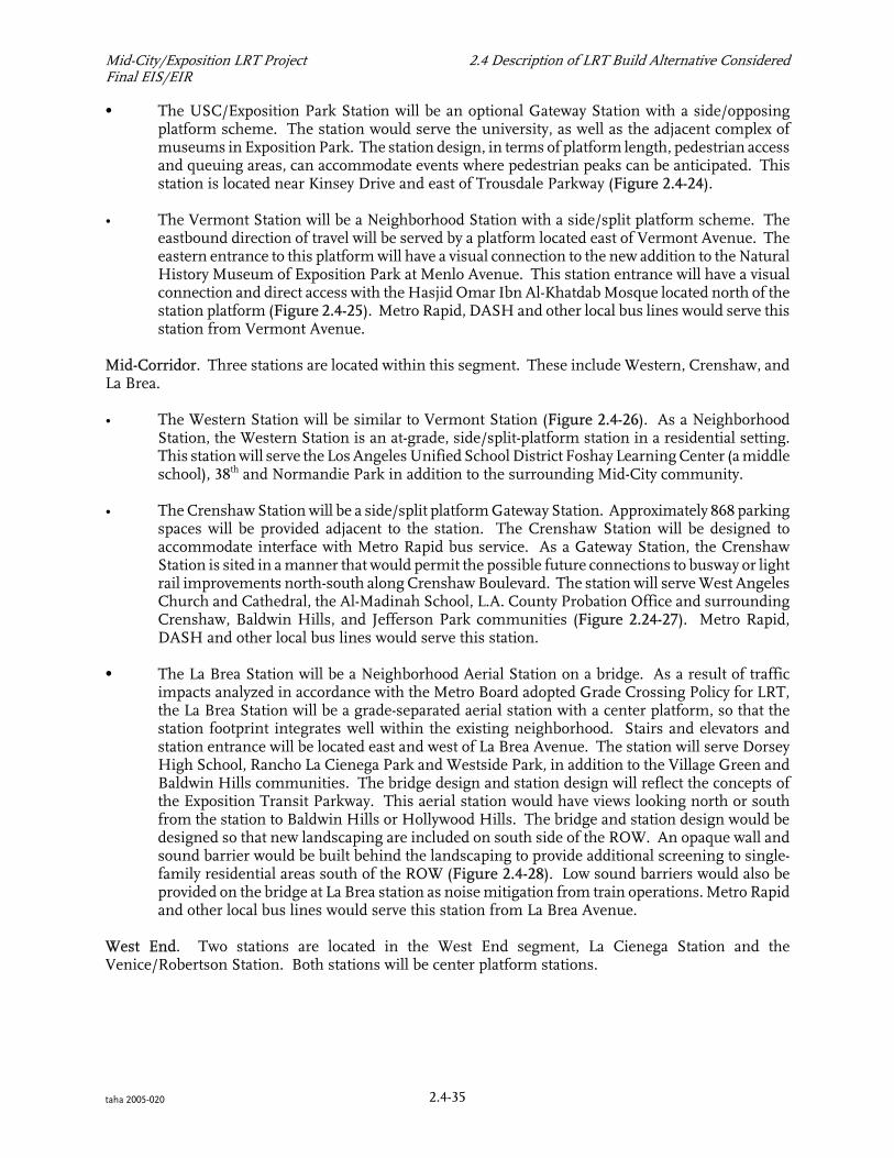
Mid-City/Exposition LRT Project 2.4 Description of LRT Build Alternative ConsideredFinal EIS/EIR
2.4-35taha 2005-020
C The USC/Exposition Park Station will be an optional Gateway Station with a side/opposingplatform scheme. The station would serve the university, as well as the adjacent complex ofmuseums in Exposition Park. The station design, in terms of platform length, pedestrian accessand queuing areas, can accommodate events where pedestrian peaks can be anticipated. Thisstation is located near Kinsey Drive and east of Trousdale Parkway (Figure 2.4-24).
• The Vermont Station will be a Neighborhood Station with a side/split platform scheme. Theeastbound direction of travel will be served by a platform located east of Vermont Avenue. Theeastern entrance to this platform will have a visual connection to the new addition to the NaturalHistory Museum of Exposition Park at Menlo Avenue. This station entrance will have a visualconnection and direct access with the Hasjid Omar Ibn Al-Khatdab Mosque located north of thestation platform (Figure 2.4-25). Metro Rapid, DASH and other local bus lines would serve thisstation from Vermont Avenue.
Mid-Corridor. Three stations are located within this segment. These include Western, Crenshaw, andLa Brea.
• The Western Station will be similar to Vermont Station (Figure 2.4-26). As a NeighborhoodStation, the Western Station is an at-grade, side/split-platform station in a residential setting.This station will serve the Los Angeles Unified School District Foshay Learning Center (a middleschool), 38th and Normandie Park in addition to the surrounding Mid-City community.
• The Crenshaw Station will be a side/split platform Gateway Station. Approximately 868 parkingspaces will be provided adjacent to the station. The Crenshaw Station will be designed toaccommodate interface with Metro Rapid bus service. As a Gateway Station, the CrenshawStation is sited in a manner that would permit the possible future connections to busway or lightrail improvements north-south along Crenshaw Boulevard. The station will serve West AngelesChurch and Cathedral, the Al-Madinah School, L.A. County Probation Office and surroundingCrenshaw, Baldwin Hills, and Jefferson Park communities (Figure 2.24-27). Metro Rapid,DASH and other local bus lines would serve this station.
C The La Brea Station will be a Neighborhood Aerial Station on a bridge. As a result of trafficimpacts analyzed in accordance with the Metro Board adopted Grade Crossing Policy for LRT,the La Brea Station will be a grade-separated aerial station with a center platform, so that thestation footprint integrates well within the existing neighborhood. Stairs and elevators andstation entrance will be located east and west of La Brea Avenue. The station will serve DorseyHigh School, Rancho La Cienega Park and Westside Park, in addition to the Village Green andBaldwin Hills communities. The bridge design and station design will reflect the concepts ofthe Exposition Transit Parkway. This aerial station would have views looking north or southfrom the station to Baldwin Hills or Hollywood Hills. The bridge and station design would bedesigned so that new landscaping are included on south side of the ROW. An opaque wall andsound barrier would be built behind the landscaping to provide additional screening to single-family residential areas south of the ROW (Figure 2.4-28). Low sound barriers would also beprovided on the bridge at La Brea station as noise mitigation from train operations. Metro Rapidand other local bus lines would serve this station from La Brea Avenue.
West End. Two stations are located in the West End segment, La Cienega Station and theVenice/Robertson Station. Both stations will be center platform stations.

FIGURE 2 -24
USC/EXPOSITION PARKSTATION AREA
.4
SOURCE: Zimmer Gunsul Frasca Partnership
MID-CITY/EXPOSITION LRT PROJECT FINAL EIS/EIRLOS ANGELES COUNTY METROPOLITAN TRANSPORTATION AUTHORITY
`
KIN
SE
YD
R
EXPOSITION BLVD
FIG
UR
EO
AST
FLO
WER
ST
Station Vicinity Surrounding Context Station Location
Note: Exact station platform locations to be determined in Final Design.

FIGURE 2 -25
VERMONT STATION AREA
.4
SOURCE: Zimmer Gunsul Frasca Partnership
MID-CITY/EXPOSITION LRT PROJECT FINAL EIS/EIRLOS ANGELES COUNTY METROPOLITAN TRANSPORTATION AUTHORITY
VE
RM
ON
TA
VE
EXPOSITION BLVD
Station Vicinity Surrounding Context Station Location
Note: Exact station platform locations to be determined in Final Design.

SOURCE: Zimmer Gunsul Frasca Partnership
MID-CITY/EXPOSITION LRT PROJECT FINAL EIS/EIRLOS ANGELES COUNTY METROPOLITAN TRANSPORTATION AUTHORITY
`
WE
ST
ER
NA
VE
EXPOSITION BLVD
Station Vicinity Surrounding Context Station Location
FIGURE 2.4-26
WESTERN STATION AREA
Note: Exact station platform locations to be determined in Final Design.

FIGURE 2 -27
CRENSHAW STATION AREA
.4
SOURCE: Zimmer Gunsul Frasca Partnership
MID-CITY/EXPOSITION LRT PROJECT FINAL EIS/EIRLOS ANGELES COUNTY METROPOLITAN TRANSPORTATION AUTHORITY
`
EXPOSITION BLVDCR
EN
SH
AW
BLV
D
Station Vicinity Surrounding Context Station Location
Note: Exact station platform locations to be determined in Final Design.

FIGURE 2 -28
LA BREA STATION AREA
.4
SOURCE: Zimmer Gunsul Frasca Partnership
MID-CITY/EXPOSITION LRT PROJECT FINAL EIS/EIRLOS ANGELES COUNTY METROPOLITAN TRANSPORTATION AUTHORITY
`
JEFFERSON BLVD
EXPOSITION BLVD
LA
BR
EA
AV
E
Station Vicinity Surrounding Context Station Location

Mid-City/Exposition LRT Project 2.4 Description of LRT Build Alternative ConsideredFinal EIS/EIR
2.4-41taha 2005-020
• The La Cienega Station will be a Gateway Station located on a bridge structure that would bridgeLa Cienega Boulevard. Two station entrances with stairs and elevators will be located on both theeast and west sides of the La Cienega Station. Approximately 530 parking spaces would beprovided in a parking structure located in the southeast quadrant of La Cienega Boulevard andJefferson Boulevard, along with a surface parking lot on the Metro ROW east of La CienegaBoulevard. This station will serve the Hayden Tract, Syd Kronenthal Park and Baldwin Hillscommunity (Figure 2.4-29). Metro Rapid, express and local bus lines would serve this stationfrom an On-street and Off-Street Transit Center located at or near the station's Parking Facility.
• The Venice/Robertson Station will be the interim terminal station for the proposed Project. ThisGateway Station will be located at ground level and will have a center platform located on thesouth side of Venice Boulevard. It will incorporate a Clean Mobility Center (CMC).Approximately 845 parking spaces will be provided at the station in three surface parking lotswithin the Exposition ROW. The parking area in the ROW north of Venice Boulevard will bedesigned to accommodate a parking structure should it be warranted in the future, and it willalso accommodate the West Los Angeles Bike Path within the Metro-owned ROW (Figure 2.4-30). Metro Rapid and local buses would serve this station in an On-Street and Off-Street TransitCenter.
Downtown Los Angeles Connection Station Options
The LPA and Design Options within the Downtown Los Angeles Connection will have the followingstations:
TABLE 2.4-4: DOWNTOWN LOS ANGELES CONNECTION DESIGN OPTIONS – STATION LOCATIONSLocally Preferred Alternative Hill Street Couplet Design Option Flower Street Design OptionsUses existing Pico Station Using existing Pico Station Uses existing Pico Station
Uses existing Grand Station N/A N/A
New Hill Street and 21st Street Stationcenter platform
New Hill Street and 21st Street Stationsplit platform
New Flower Street and 23rd Streetsplit/side platform stations
Designed not to preclude a futurestation at Hill Street and JeffersonBoulevard
Designed not to preclude a futurestation at Hill Street and JeffersonBoulevard or at 17th/18th Street/GrandAvenue
New Flower Street and JeffersonBoulevard split/side platform station
USC/Exposition Park Station at KinseyDrive
USC/Exposition Park Station at KinseyDrive
USC/Exposition Park Station atKinsey Drive (Applies USC/ExpositionUndercrossing option only, not at theModified and Extendedundercrossing options)
Note: For station plans see Appendix H, bound separately.SOURCE: Los Angeles Metropolitan Transit Authority, 2004

FIGURE 2 -29
LA CIENEGA STATION AREA
.4
SOURCE: Zimmer Gunsul Frasca Partnership
MID-CITY/EXPOSITION LRT PROJECT FINAL EIS/EIRLOS ANGELES COUNTY METROPOLITAN TRANSPORTATION AUTHORITY
JEFFERSON BLVD
LA
CIE
NE
GA
BLV
D
MIXED-USE
OPPORTUNITY SITE
Station Vicinity Surrounding Context Station Location
Parking
Facilities

FIGURE 2 -30
VENICE/ROBERTSON STATION AREA
.4
SOURCE: Zimmer Gunsul Frasca Partnership
MID-CITY/EXPOSITION LRT PROJECT FINAL EIS/EIRLOS ANGELES COUNTY METROPOLITAN TRANSPORTATION AUTHORITY
VEN
ICE
BLV
D
NATIO
NAL
BLVD
10FR
EEW
AY
WASH
ING
TON
BLV
D
RO
BE
RT
SO
NB
LV
D
EXPOSITION BLVD
PARK-AND-RIDE/`
CLEAN MOBILITY
CENTER
OPPORTUNITY
PARK-AND-RIDE
OPPORTUNITY
PARK-AND-RIDE
OPPORTUNITY
Station Vicinity Surrounding Context
Station Location

Mid-City/Exposition LRT Project 2.4 Description of LRT Build Alternative ConsideredFinal EIS/EIR
2.4-44taha 2005-020
2.4.2.1.1c Parking Facilities
Parking facilities is defined as car parking facilities assigned to the Project. These facilities are providedand assigned to Mid-City/Exposition LRT stations based on ridership forecast and demand. The role andpurpose of this element is to provide park and ride facilities and other types of car parking and cartransfer facilities to allow for transfer of passengers from an automobile mode to transit or non-motorized mode provided by the Project. Parking numbers described below are for the year 2020demand. Fewer parking spaces may be provided on opening day. Replacement parking for the Projectis not part of this element of the Exposition Transit Parkway, and is discussed separately in Section 3.2Parking. Parking facilities for the Project will be assigned to the following segments of the RouteAlignment:
Downtown Los Angeles Connection. No parking facilities will be provided within this segment of theProject.
Mid-Corridor. Parking for 868 vehicles will be provided at Crenshaw Station in existing lots northeastof Crenshaw and Exposition Boulevards, north of Crenshaw Station and within the Station Vicinity area,adjacent to commercial uses. This could occur, for example, by sharing existing parking spaces with theWest Los Angeles Cathedral or others. A "Kiss-and-Ride" drop off and waiting area will be located southof the station on Exposition Place, east of Crenshaw Boulevard. A "Kiss-and-Ride" drop off and waitingarea will be provided immediately south of the La Brea station platform on Exposition Boulevard south.Access to the drop off area will be off of La Brea Avenue and a reconfigured access road across the ROWfrom Exposition Boulevard north.
West End. Both stations in the West End would have Parking Facilities.
• La Cienega Station - Approximately 530 parking spaces will be provided in a multi-level parkingstructure and a surface lot in the ROW. The multi-level parking structure will be located on thesoutheast corner of La Cienega and Jefferson Boulevards within the Station Site of La CienegaStation. Street level retail amenities will be part of the parking structure. An On-Street TransitCenter will be provided in front of the parking structure on La Cienega Boulevard, facing thestreet level retail amenities. An On-Street Transit Center will also be provided on the groundlevel of the parking structure The parking structure will provide driveway access from La Cienegaand Jefferson Boulevards. Driveway access and circulation of transit buses will be provided aspart of the ground floor level of the parking structure. A drop-off and waiting area will beprovided on the north side of the parking structure on the ROW, south of Jefferson Boulevard.
The proposed La Cienega station would be situated on a major, regional north-south corridorserving transit users from both the South Bay and Hollywood. A large parking facility isproposed to serve the needs of park-and-ride transit users coming from these surrounding areas.The City of Los Angeles currently owns the site for the proposed La Cienega parking facility. TheCity has used this site as part of the East Central Interceptor Sewer (ECIS) improvement project.The City has a continuing need for a portion of the site as an air treatment facility for sewerodors. Through the City’s real property disposition process, Metro is seeking to acquire the otherportion of the site not needed for air treatment equipment. In response, the City of Los AngelesCity Council adopted a resolution in November 2004 requiring Council review before dispositionof the property. The City has taken this action to ensure that alternate uses for the site other thantransit and parking are considered. Due to the potential for the City to reserve this site for otheruses, options to the La Cienega parking facility were generated. One option would relocate theparking facility to the opposite side of La Cienega Boulevard, on the southwest corner of LaCienega and Jefferson Boulevards. This option would require the acquisition of private property.The second option would redirect parking demand to other parking facilities along thealignment.

Mid-City/Exposition LRT Project 2.4 Description of LRT Build Alternative ConsideredFinal EIS/EIR
2.4-45taha 2005-020
• Venice/Robertson Station - Approximately 845 parking spaces will be provided in surface lotswithin the Metro ROW, within the Station Area, within the Station Vicinity, within and outsidethe Station Influence Area. Three categories of parking facilities will be provided in three zonesof the station:
• Drop Off/Waiting - Also known as “Kiss-and-Ride” facility located north of the LRTplatform on Exposition Boulevard, within the Station Site area.
• Midday Parking - Provided in surface parking lots with 68 spaces provided south of thestation platform within the Station Site and partially in the Station Vicinity area. Forty-two (42) spaces are provided southeast of the station platform in the ROW within theStation Vicinity and partially in the Station Influence area.
• Commuter Parking - 735 spaces in a surface parking lot west of Venice Boulevard in theExposition ROW.
2.4.2.1.1.d Bikeway and Bikeway Facilities
Bikeway Description
The Project includes a proposed bikeway facility, running parallel to the route alignment of the LRT,from Vermont Station to Venice/Robertson station. The proposed bikeway would have directconnections to the Ballona Creek Bikeway west of La Cienega Boulevard, the Venice Boulevard bike lanesat Venice/Robertson Station and would provide a connection to the western extension of the ExpositionWest Bike Path located on the Exposition ROW, west of Venice Boulevard. On the eastern end of thebikeway, direct connections can be made from the bikeway at Vermont Station to Exposition Park.
The following describes bikeway definitions to be used throughout the discussion of this element of theProject and throughout the document:
• Bike Route - Class III bikeways (bike routes) are established by placing Bike Route signs alongroadways and used to connect discontinuous segments of bikeways for continuity to the bikewaysystem.
•
Class I bikeways (bike paths) are facilities with exclusive Right of Way, with crossflows by motorists minimized.
• On-street bikeway - An on-street bikeway is comparable to a Class II bike lane. Signage adjacentto the street indicates where the bikeway is located, and the on-street bikeways are separatedfrom the flow of traffic by striping.
• Off-street bikeway - An off-street bikeway is comparable to a Class I bikeway or bike path.
The discussion that follows details the characteristics of the bikeway’s route alignment (Figure 2.4-31):
• Mid-Corridor. The Project’s bikeway alignment begins west of Vermont Avenue across the LRTplatform of the Vermont Station. Eastbound and westbound Class II bike lanes on-street (fivefeet in width) would be located on north and south sides of Exposition Boulevard betweenVermont and La Brea Avenues.

SANTA
MONICA
CULVER CITY
MARINA
DEL REY
DOWNTOWN
LOS ANGELES
BEVERLY
HILLS
PR
AIR
IEA
VE
SE
PU
LV
ED
AB
LV
D
AIR
PO
RT
BLV
D
SLAUSON AV
LUTHER KING JR BLVD
EXPOSITION BLVD
VE
RM
ON
TA
V
FIG
UE
RO
AS
T
CR
EN
SH
AW
BLV
D
LA
CIE
NE
GA
BLV
D
CU
LVER
BLV
D
OV
ER
LA
ND
AV
RODEO
PICO
BLVDW
ILSHIR
EBLV
D
SANTA
MO
NIC
ABLV
D
OLYMPIC
BLVD
OLY
MPIC
SAN
VICEN
TE
BLVD
LINCOLN
AV
OV
ER
LA
ND
AV
WILSHIRE BLVD
OLYMPIC BLVD
BEVERLY BLVD
PICO BLVD
OLYMPIC BLVD
VE
RM
ON
TA
V
HO
OV
ER
ST
LINCOLNBLVD
CENTINELA
MELROSE AV
SANTA MONICA BLVD
SUNSET BLVD
SANTAM
ONIC
ABLVD
SE
PU
LV
ED
AB
LV
D
PA
CIF
ICB
LV
D
AL
AM
ED
AS
T
SLAUSON AV
FLORENCE AV
TIJERA
BLV
D
MANCHESTER BLVD FLORENCE
AV
MANCHESTER BLVD
FLORENCE AV
8th
ST
SLAUSON AV
VERNON AV
NM
AINST
SPRING
ST
TEMPLEST
CESAR
BEVERLY BLVD
NM
ISSIO
N
CO
MP
TO
NA
V
BU
ND
YD
R
VENICE
BLVD
PICO
BLVD
RO
BE
RT
SO
NB
LV
D
LA
CIE
NE
GA
BLV
D
FA
IRF
AX
AV
VENICE BLVD
WASHINGTON BLVD
ADAMS BLVD
NO
RM
AN
DIE
AV
NO
RM
AN
DIE
AV
WE
ST
ER
NA
VW
ES
TE
RN
AV
CR
EN
SH
AW
BLV
DA
RL
ING
TO
NA
V
SO
TO
ST
SA
NTA
FE
AV
ADAMSBLVD
WASHINGTONBLVD
JEFFERSONBLVD
PICOBLVD
9th ST
6thST
3rdST
ALVA
RA
DO
ST
UN
ION
AV
ALVA
RA
DO
ST
FLO
WER
ST
FIG
UE
RO
AS
T
WILSHIRE
BLVD
WASHIN
GTON
OCEANPARK
BLVD
BLVD
MO
NTA
NA
AV
WILSHIRE BLVD
3rd ST
JEFFERSON BLVD
SAN VICENTE BLVD
SUN SET
BLV
D
SUNSET
BLV
D
BLVD
RD
MARTIN
STOCKER ST
SO
TO
ST
AL
AM
ED
AS
T
CE
NT
RA
LA
V
WESTW
OO
DB
LVD
OC
EA
NAV
LA
BR
EA
AV
WIL
TO
NP
L
HIG
HL
AN
DA
V
LA
BR
EA
AV
HOLLYWOOD BLVD
SUNSET
BLV
D
HOLLYWOOD BLVD
CHAVEZ AV
DODGER
STADIUM
Union
Station
PA
CIF
IC
OC
EA
N
U.C.L.A.
U.S.C.
Westwood
Village
405
10
2
110
405
5
90
101
SANTA MONICA
10
HOLLYWOOD
HOLLYWOOD
WEST
PP
P
Red
Lin
e
Blu
eLin
e
Red Line
Gol
dLi
ne
Eastside Line
GRAN
D/W
ASH
ING
TON
GRAN
D/W
ASH
ING
TON
GRAN
D/W
ASH
ING
TON
PIC
O
PIC
O
VENIC
E/R
OBERTSON
VENIC
E/R
OBERTSON
LA
CIE
NEG
A
LA
CIE
NEG
ALA
BREA
LA
BREA
CRENSHAW
CRENSHAW
WESTERN
WESTERN
VERM
ON
T
VERM
ON
TUSC/E
XPOSIT
ION
PARK
USC/E
XPOSIT
ION
PARK
21ST
STREET
21ST
STREET
21ST
STREET
NORTH
7THST/M
ETROCTR
7THST/M
ETROCTR
SANTA
MONICA
CULVER CITY
MARINA
DEL REY
DOWNTOWN
LOS ANGELES
BEVERLY
HILLS
PR
AIR
IEA
VE
SE
PU
LV
ED
AB
LV
D
AIR
PO
RT
BLV
D
SLAUSON AV
LUTHER KING JR BLVD
EXPOSITION BLVD
VE
RM
ON
TA
V
FIG
UE
RO
AS
T
CR
EN
SH
AW
BLV
D
LA
CIE
NE
GA
BLV
D
CU
LVER
BLV
D
OV
ER
LA
ND
AV
RODEO
PICO
BLVDW
ILSHIR
EBLV
D
SANTA
MO
NIC
ABLV
D
OLYMPIC
BLVD
OLY
MPIC
SAN
VICEN
TE
BLVD
LINCOLN
AV
OV
ER
LA
ND
AV
WILSHIRE BLVD
OLYMPIC BLVD
BEVERLY BLVD
PICO BLVD
OLYMPIC BLVD
VE
RM
ON
TA
V
HO
OV
ER
ST
LINCOLNBLVD
CENTINELA
MELROSE AV
SANTA MONICA BLVD
SUNSET BLVD
SANTAM
ONIC
ABLVD
SE
PU
LV
ED
AB
LV
D
PA
CIF
ICB
LV
D
AL
AM
ED
AS
T
SLAUSON AV
FLORENCE AV
TIJERA
BLV
D
MANCHESTER BLVD FLORENCE
AV
MANCHESTER BLVD
FLORENCE AV
8th
ST
SLAUSON AV
VERNON AV
NM
AINST
SPRING
ST
TEMPLEST
CESAR
BEVERLY BLVD
NM
ISSIO
N
CO
MP
TO
NA
V
BU
ND
YD
R
VENICE
BLVD
PICO
BLVD
RO
BE
RT
SO
NB
LV
D
LA
CIE
NE
GA
BLV
D
FA
IRF
AX
AV
VENICE BLVD
WASHINGTON BLVD
ADAMS BLVD
NO
RM
AN
DIE
AV
NO
RM
AN
DIE
AV
WE
ST
ER
NA
VW
ES
TE
RN
AV
CR
EN
SH
AW
BLV
DA
RL
ING
TO
NA
V
SO
TO
ST
SA
NTA
FE
AV
ADAMSBLVD
WASHINGTONBLVD
JEFFERSONBLVD
PICOBLVD
9th ST
6thST
3rdST
ALVA
RA
DO
ST
UN
ION
AV
ALVA
RA
DO
ST
FLO
WER
ST
FIG
UE
RO
AS
T
WILSHIRE
BLVD
WASHIN
GTON
OCEANPARK
BLVD
BLVD
MO
NTA
NA
AV
WILSHIRE BLVD
3rd ST
JEFFERSON BLVD
SAN VICENTE BLVD
SUN SET
BLV
D
SUNSET
BLV
D
BLVD
RD
MARTIN
STOCKER ST
SO
TO
ST
AL
AM
ED
AS
T
CE
NT
RA
LA
V
WESTW
OO
DB
LVD
OC
EA
NAV
LA
BR
EA
AV
WIL
TO
NP
L
HIG
HL
AN
DA
V
LA
BR
EA
AV
HOLLYWOOD BLVD
SUNSET
BLV
D
HOLLYWOOD BLVD
CHAVEZ AV
DODGER
STADIUM
Union
Station
PA
CIF
IC
OC
EA
N
U.C.L.A.
U.S.C.
Westwood
Village
405
10
2
110
405
5
90
101
SANTA MONICA
10
HOLLYWOOD
HOLLYWOOD
WEST
PP
P
Red
Lin
e
Blu
eLin
e
Red Line
Gol
dLi
ne
Eastside Line
GRAN
D/W
ASH
ING
TON
GRAN
D/W
ASH
ING
TON
GRAN
D/W
ASH
ING
TON
PIC
O
PIC
O
VENIC
E/R
OBERTSON
VENIC
E/R
OBERTSON
LA
CIE
NEG
A
LA
CIE
NEG
ALA
BREA
LA
BREA
CRENSHAW
CRENSHAW
WESTERN
WESTERN
VERM
ON
T
VERM
ON
TUSC/E
XPOSIT
ION
PARK
USC/E
XPOSIT
ION
PARK
21ST
STREET
21ST
STREET
21ST
STREET
NORTH
7THST/M
ETROCTR
7THST/M
ETROCTR
Future City of Los Angeles
Exposition West Bike Path
Future City of Santa
Monica Exposition
Bike Path
Ballona
Creek
Bikew
ay
Venice
Bouleva
rdBik
eway
Coasta
lBik
ePath
Off-StreetOn-Street
On-Street
SOURCE: Terry A. Hayes Associates LLC, 2004
FIGURE 2 -31
BIKEWAY ROUTE ALIGNMENT
.4MID-CITY/EXPOSITION LRT PROJECT FINAL EIS/EIRLOS ANGELES COUNTY METROPOLITAN TRANSPORTATION AUTHORITY

Mid-City/Exposition LRT Project 2.4 Description of LRT Build Alternative ConsideredFinal EIS/EIR
2.4-47taha 2005-020
a transition so that cyclists will stop at Gramercy Place and walk their bikes over to the eastboundbike lane where Rodeo Road transitions to Exposition Boulevard south (Figure 2.4-32).
At Harcourt Avenue, cyclists would have a choice of transitioning to Jefferson Boulevard andriding on the street or use crosswalks along with pedestrians (Figure 2.4-33). At JeffersonBoulevard, bike lanes would be constructed on the north and south sides of Jefferson Boulevardto La Cienega Boulevard. Bike lanes would also continue on Exposition Boulevard beyondHarcourt Avenue to connect with the entry plaza at La Brea Station.
• West End. On-street bike lanes would be provided on the north and south sides of JeffersonBoulevard and west of La Cienega Boulevard. At a point just west of La Cienega Boulevard, anentrance to an off-street bikeway would be created. The westbound bike lane would transitioninto this entrance. Eastbound bicyclists – using the off street bikeway– would be required todismount and cross Jefferson Boulevard at the Jefferson/National traffic signal. The off-streetbikeway would use the existing National Boulevard bridge over Ballona Creek (the bridge wouldbe vacated for automobile use by the Project) (Figure 2.4-34). The bikeway would provide afuture connection to the ramp to the existing Ballona Creek Bike Path near this location.
The off-street bikeway would continue to Wesley Street where bicyclists would be directed throughsignage and pavement markings to either use crosswalks to enter the Venice/Robertson Station area orto proceed along National Boulevard to either intersect the bike lanes on Venice Boulevard or to connectto the future Exposition West Bike Path which would use the Metro-owned ROW west of VeniceBoulevard (Figure 2.4-35). A dedicated and separate bike path (12 feet wide) would be created along thesouth edge of the proposed Venice/Robertson Station parking facility which would also be located in theROW.
Outside of the proposed bikeway alignment, connections can be made to other bikeways at the followingsegments:
• Downtown Los Angeles Connection. The Project’s bikeway would connect to a Class 3 BikeRoute extends past USC and Exposition Park along Exposition Boulevard from Vermont Avenueto Figueroa Street. A Class 3 Bike Route extends from Exposition Boulevard at Figueroa Streetto Olympic Boulevard towards Downtown Los Angeles.
• West End. The proposed bikeway would have direct connections to the Class 1 Ballona CreekBikeway meeting the Class 1 bike path of the Project’s bikeway at Ballona Creek, near SydKronenthal Park. The Project’s bikeway would also connect to the Venice Boulevard Bike Lanesnorth of the Project’s western terminus and would provide a connection to the future ExpositionWest Bike Path located on the Exposition ROW west of Venice Boulevard.

SOURCE: DMJM Harris
FIGURE 2 -32EXPOSITION BOULEVARD AT
RODEO ROAD BIKE LANE TRANSITION
.4
5’ Bike Lane WB 5’ Bike Lane WB
Bike Lane EB
5’ Bike Lane EB
5’ Bike Lane EB
MID-CITY/EXPOSITION LRT PROJECT FINAL EIS/EIRLOS ANGELES COUNTY METROPOLITAN TRANSPORTATION AUTHORITY
EB or WB Cyclists have a choice
to cross or turn at the signalized
intersections at the pedestrian
cross walks, or ride on the street
as a vehicle.
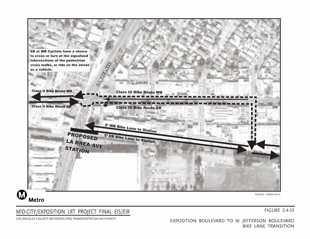
LA
BR
EA
AV
E
LA
BR
EA
AV
E
PROPOSEDLA BREA AVESTATION
PROPOSEDLA BREA AVESTATION
HA
RC
OU
RT
RIM
PA
U
EXPOSITION BLVD
SOURCE: DMJM Harris
Class III Bike Route WB
5’ WB Bike Lane to Station
Class II Bike Route WB
EB or WB Cyclists have a choice
to cross or turn at the signalized
intersections at the pedestrian
cross walks, or ride on the street
as a vehicle.
Class III Bike Route EB
5’ EB Bike Lane to Station
Class II Bike Route EB
LA
BR
EA
AV
E
HA
RC
OU
RT
RIM
PA
U
EXPOSITION BLVD
PROPOSEDLA BREA AVESTATION
FIGURE 2 -33
EXPOSITION BOULEVARD TO W. JEFFERSON BOULEVARDBIKE LANE TRANSITION
.4MID-CITY/EXPOSITION LRT PROJECT FINAL EIS/EIRLOS ANGELES COUNTY METROPOLITAN TRANSPORTATION AUTHORITY

FIGURE 2 -34JEFFERSON BOULEVARD AT
NATIONAL BOULEVARDBIKE LANE/BIKE PATH TRANSITION
.4
NATIONAL BLVD
JE
FF
ER
SO
NB
LV
D
Existing National Blvd
Bridge Converted to
“Bikes Only”
Access Point to
Ballona Creek Bikeway
Widened & Realigned
National Blvd
5’ Bike Lane WB
Off-Street 12’ Bikeway
5’ Bike Lane EB
SOURCE: DMJM Harris
MID-CITY/EXPOSITION LRT PROJECT FINAL EIS/EIRLOS ANGELES COUNTY METROPOLITAN TRANSPORTATION AUTHORITY
EB or WB Cyclists have a choice
to cross or turn at the signalized
intersections at the pedestrian
cross walks, or ride on the street
as a vehicle.
LRT guideway

FIGURE 2 -35WASHINGTON BOULEVARD AT
NATIONAL BOULEVARDBIKE PATH TRANSITION
.4
NATIONALBLVD
Park
From Venice Boulevard
Bike Lanes or Exposition
West Bike Path
To Venice Boulevard
Bike Lanes or Exposition
West Bike Path
End of Class I
12’ wide Bike Path
Venice/Robertson
Station
Crossing
Gates
Crossing
Gates
SOURCE: DMJM Harris
MID-CITY/EXPOSITION LRT PROJECT FINAL EIS/EIRLOS ANGELES COUNTY METROPOLITAN TRANSPORTATION AUTHORITY

Mid-City/Exposition LRT Project 2.4 Description of LRT Build Alternative ConsideredFinal EIS/EIR
2.4-52taha 2005-020
Bicycle Facilities at Stations
Bicycle parking will be provided at every station along the alignment with the exception of stationslacking adequate space, such as, at 7th Street/Metro Station. Racks and lockers will meet Metro bikewayplanning group specifications. A minimum of ten inverted U racks (five in close proximity to eachplatform) will be provided within access to each station entrance, where space allows. Four secure bikelockers will be provided at each station without a parking facility except for stations without adequatespace. Eight secure bicycle parking spaces (lockers or a locked enclosure) will be provided with room forexpansion as demand increases, at each station with a parking facility. The bicycle parking will belocated within close proximity to handicapped car parking. Bicycle parking should be no further fromthe station entrance than the closest car parking. If shared parking lots are utilized, bicycle parkingagreements need to be made between Metro and the property owner to provide space for secure bicycleparking to be managed by Metro.
Table 2.4-5 provides a summary of the Mid-City/Exposition LRT Project bicycle facilities.
TABLE 2.4-5: BICYCLE FACILITIES SUMMARY
Station Name Bicycle Rack/Locker Requirement /a/ Location Guidelines
DOWNTOWN LOS ANGELES CONNECTION
7th St./Metro Center None provided in this Project N/A
Pico Station 10 racks/4 lockers racks located close to station platform
Washington Blvd/Grand AveStation
10 racks/4 lockers racks located close to station platform
21st St./Hill St. 10 racks/4 lockers racks located close to station platform
USC/Exposition Park 10 racks/4 lockers racks located close to station platform
Vermont Station 10 racks/4 lockers racks located close to station platform
MID-CORRIDOR
Western Station 10 racks/4 lockers racks located close to station platform
Crenshaw Station 10 racks/8 lockers or locked enclosure lockers located at Crenshaw and La CienegaParking Facilties
La Brea Station 10 racks/4 lockers lockers located at Crenshaw and La CienegaParking Facilities
WEST END
La Cienega Station 10 racks/8 lockers or locked enclosure lockers located at Crenshaw and La CienegaParking Facility
Venice/Robertson Station See Clean Mobility Center Clean Mobility Center programrequirements
STATION OPTIONS
23rd St./Flower St. 10 racks/4 lockers racks located close to station platform
Jefferson/Flower St. 10 racks/4 lockers racks located close to station platform
17th St. and 18th St. 10 racks/4 lockers racks located close to station platform
Jefferson/Hill St. 10 racks/4 lockers racks located close to station platform
/a/ Exact rack and locker quantities to be determined in Final Design.SOURCE: Metro, 2004.

Mid-City/Exposition LRT Project 2.4 Description of LRT Build Alternative ConsideredFinal EIS/EIR
2.4-53taha 2005-020
Bikeway Features
Bike lanes are designed for bicyclists to share the roadway with, and use the same intersectionssignalization and cross walks as motorists and pedestrians. At certain intersections, bicycle specificsignal phasing may be introduced where conditions warrant. Additional design features include roadwaysurface improvements and wayfinding signage and graphics. In addition to the striped bike lanes,design, and signage, striping standard will follow the Caltrans Highway Design Manual Chapter 1000or the State-adopted MUTCD.
In Culver City, directional patterns designed by the Project’s lead artist will be applied to the surface ofthe Class 1 (off-street dedicated ROW) bike path. The patterns will be configured to create a ‘warningcode’ that instruct bike riders to slow down for street crossing intersections and transitions onto theClass 2 (on-street) bike-lanes at Jefferson and National Boulevards. The patterns are envisioned as awoven motif that would be applied using traffic paint or thermal plastic film which are inexpensive, easyto maintain, have a reflective quality for night riding, and do not create trip hazards. Use of earthenberms and landscape planting may also be used to enhance delineation of the Class 1 bike path anddesignate it as a strand of the Exposition Transit Parkway. The bikeway would also include consistentuniform way-finding signage, graphics and bikeway maps.
2.4.1.1e Landscaping, Public Art and Other Transit Parkway Improvements
Landscaping Plan
The Exposition Transit Parkway focuses on improved landscape design throughout the corridor. The goalof this landscaping plan is to implement the Exposition Transit Parkway using landscape concepts, whichwould:
• Create a distinct and positive image to the neighborhoods along the alignment.• Provide a sustainable alignment;• Be reasonable to maintain; and• Be economical to build;
The landscape installations for the Exposition Transit Parkway are designed to enhance and invitecustomers onto the system. Improvements may include extensive plantings, earthen berms, enhancedfencing, landscape-veiled structural walls, sound walls and fencing, and other features. Theseinstallations will mitigate the visual impacts of the alignment. Wherever possible, all of the landscapeelements will be designed with input from the Lead Artist so that landscape and structure appearthematically woven together. Woven decorative patterns conceptualized by the Lead Artist may also beincorporated into the design of structural walls, sound walls and fencing. While also creating asculptural interest, the elements may also help deter graffiti.
Stations and bridges will be landscaped efficiently wherever possible, including in restricted, elevatedspaces such as hills and walls. This will further reduce visual impact and will reinforce the image of acohesive green corridor. The color, texture and massing of trees and plantings will create visual interestto passengers and will screen undesirable views from residential areas. The trees, shrubs and groundcovers suggested in the landscaping plan have been recommended for their longevity, low maintenancerequirements and drought tolerance.
Local needs of residential and other property owners will be taken into consideration in providingadequate screening and buffering adjacent to the Project. Where feasible, planting and woven patternsconceptualized by the Lead Artist may cover large unadorned walls, and would be used to screen lightrail equipment such as valves, transformers, electrical substations and other mechanical devices that mayvisually impact residents. These measures will further help deter graffiti, especially in difficult tosupervise areas. Walkways and linkages from adjacent neighborhoods will be enhanced to reinforce

Mid-City/Exposition LRT Project 2.4 Description of LRT Build Alternative ConsideredFinal EIS/EIR
2.4-54taha 2005-020
neighborhood places and signal the act of arrival at stations. Levels of landscaping provided by theProject would be consistent with the landscape levels provided for Metro Orange Line and Metro Goldline (Pasadena).
Landscaping improvements include:
• Removal of existing soils, rough and fine grading;• Soil amendments;• Soil top dressing and mulching;• Automatic irrigation system;• Surveying, evaluation, removal or relocation of existing trees;• Planting of new trees, shrubs, espaliers, vines and vines; and• Coordination and planting on walls, fencing, arbors and other landscape structural features.
Planting Guidelines. The planting areas within the transit parkway are located outside of the traindynamic envelope on the north and south sides and within the Metro ROW. Available planting areasvary due to the track alignment within the Metro ROW, and varying width of the ROW.
The following principles are used as a general guideline to the planting palette/design:
• Use water conserving plant materials, employ water conserving irrigation techniques, screenundesirable views, frame desirable views, assist in buffering noise at appropriate locations,provide longevity, use hardy materials.
C A single tree species and a single shrub species is recommended to continue the entire lengthof the alignment, with the exception of those areas where space is otherwise restricted.
The landscape concept developed as part of the environmental process suggests that the remaining plantmaterials consists of palette groupings, having an individual color assigned to them, which the plantcharacteristics have (i.e., flower color, leaf color, etc.) These individual pallettes are designated to mini-segments, within the Mid-Corridor segment, that are massed by color theme and transition from onecolor theme to another along the route, the landscape theme recommends.
• Serpentine (weaving) masses of shrubs and ground cover with layers of texture and heightprovided between stations in direct contrast to the lines created by single tree and hedge speciesdescribed above;
• Accent trees at street intersections, in variation of appropriate colors;• Vines/Espaliers on the fences and walls along the route at strategic locations;• The landscape transitions from the above design concept to the station areas by introducing
another layer;• Columnar trees placed in a rhythmic pattern;• Blocks of colored ground plane plant materials used in the same rhythm as the columnar trees
mentioned above; and• Each station provided with its own identity by following the prescribed color theme, and at the
same time, maintain a definite cohesion throughout the alignment.
Landscape Planting at Corridors. Space for planting along the linear corridors of the Exposition TransitParkway is variable and frequently narrow as it traverses the more urbanized and traveledneighborhoods. In these narrow areas, four- to five-foot wide planters along fences lines and adjacentto the roadways will be planted with low masses of hedge and accent plantings. Trees other than palmswill need periodic pruning so that there is no growth into the train dynamic envelope. Rather thanindividual branch shaping and thinning, trees adjacent to the tracks may be massed sheared periodicallyto create a “green wall” outside the adjacent fence line.

Mid-City/Exposition LRT Project 2.4 Description of LRT Build Alternative ConsideredFinal EIS/EIR
2.4-55taha 2005-020
C Vines shall be planted no more than 12 feet on center on walls and fences. Vines on fencesshould be trimmed and maintained to encourage dense growth while not allowing undesiredgrowth into the rail Right of Way.
C A tree spacing of 35 feet on center is suggested within the Right of Way. Tree and tree wellsshall conform to local jurisdictional standards. All permits and approvals shall be obtained fortree planting outside of Metro Right of Way.
C Trees shall be kept at least five feet from roadway pavement, where feasible. Trees within fivefeet of pavement shall have root barriers.
C The width between the roadway and the clear rail envelope varies. Tree selection and placementshould take into consideration overhanging branches into private property or into the publicroadway. The Exposition Transit Parkway design concept is to create a park like edge along therail line and to buffer the view, noise and motion of the trains as much as possible from adjacentproperties.
C Effort should be made to place plantings in strategic places that screen negative views, reduceglare, impede graffiti on walls and deter foot traffic into or near dangerous rail and utilityservices.
C The landscape should allow for a path for Metro security and maintenance personnel. Openingsin the fences or walls should not be blocked by landscape plantings.
C In many places where space or maintenance in limited, it is encouraged that ground areas becovered with natural coarse shredded bark mulch or ornamental river cobblestone. Mulchshould be resistant to wind and fire hazards while river cobble should be anchored to a concretegrout bed (without joints) so as to discourage removal.
Landscape Planting at Stations. At stations and at major intersections, there is a desire to create visualimpact and diversity by specifying particular flowering tree specimens of unusual or dramatic form andtexture. For more interest and diversity in midst of the structured unity of fences, walls and stationstructures, it is recommended that specific stations be assigned color themes for the flowering plantmaterials. The following guidelines should also be considered:
C Yellows, oranges, violet, reds and other colors should be used in monochromatic masses atspecific stations.
C Consider columnar trees planted in linear rows, where feasible, along the station platform toidentify the station and the route of the Project.
C Where feasible, isolated or strategic planters near major entrance to stations should containunusual and striking specimen trees or plantings that give unique character to the particularstations. Planters should be low maintenance and drought tolerant.
Parking Facilities. In provided parking facilities adjacent to the stations, streets and the ROW, trees areto be planted within surface parking lots following local ordinances. If feasible, a 24-inch box tree shouldbe provided as a standard tree type to be planted in surface parking lots. Views of parked vehiclesadjacent to roadways and driveways shall be screened by no taller than 36-inch planting screens orhedges. Where possible, all surface parking lots included within the Metro ROW would have permeablesurfaces.
Integrated Corridor Features

Mid-City/Exposition LRT Project 2.4 Description of LRT Build Alternative ConsideredFinal EIS/EIR
2.4-56taha 2005-020
Public art, safety devices and Metro signage are visual elements that would be associated with theExposition Transit Parkway. Public Art conceptualized by the Lead Artist will further the visual motifof weaving and will be carried through all new stations. Safety devices seek to ensure the safety ofpedestrians and motorists while public signage and graphics would keep transit users as informed aspossible of transit options and pertinent schedules.
Public Art and System Elements.
Due to the unique nature of art and the significance of operational impacts, and in order to ensurecuratorial appropriateness, the public art program must be implemented and managed by an expert inboth the public art field and public transportation (see Section 4.4 Visual Quality of this document).
In support of the EIR effort, Metro has commissioned a Lead Artist to work with the Project’s DesignTeam to develop relevant, integrated public art opportunities with a cohesive aesthetic. With the LeadArtist’s input, the concept of weaving the structural and landscaped elements of the Parkway has beendeveloped during PE and will require further refinement during Design/Build.
System Wide Elements to be designed with Lead Artist input include:
• Canopies: The concept of weaving has a strong sculptural presence in all aspects of the canopystructure and will create interesting shadow patterns on bare concrete expanses.
• Entry installations: Vertical woven forms strategically positioned at station entrances will serveas landmarks for commuters and will help define gateway and neighborhood stations.
• Bridges, Sound Walls, Structural Walls and Fences: Will be some of the most imposing aspectsof the parkway and their impact may be softened and made more appealing with input from theLead Artist. The integration of woven forms in these surfaces will also serve as graffiti deterrentas highly textured and patterned surfaces are difficult to tag. The inclusion of art also helps todeter vandalism as it provides the impression of a more controlled and meaningful environment.Construction methods available to integrate woven patterns include sandblasting, form work andpatterned brick or block.
• Bollets: Small sculptural forms that help define the alignment in dense urban areas where thereis little room for tree planting. These may help serve as a warning code in pedestrian areas.
• Bikeway: Note that all bikeway embellishment will need to undergo appropriate safety review (seeBikeway Features).
In addition to the Lead Artist who will work on the systemwide elements, individual Station Artists willbe contracted at a later date to design, fabricate and install feature artworks for each individual station.Station Artist projects will address the environmental and cultural contexts of their appointed station.
Station Artist Opportunities will include:
• Paving: Platform areas dedicated to embellishment in prominent locations. Only materials withproven durability in highly trafficked public places will be considered, such as: colored, texturedor stamped concrete. Lithocrete (glass, shell or ceramic embedded concrete), terrazzo and trafficpaint and thermal film.
• Seating: Design or selection of a system-wide bench whose form or surface may be embellishedor adapted by Station Artists (e.g. a concrete bench with decorative sandblasted surface motif).
Free standing sculpture: may help define the character of each individual station while serving as arrivalmarkers for customers. Suitable materials include concrete, GFRC, granite, stainless steel and ceramictile.
A budget will be established for the Project’s public art program, and shall be appropriate to the overallcosts of the Project and adequate to have an impact.

Mid-City/Exposition LRT Project 2.4 Description of LRT Build Alternative ConsideredFinal EIS/EIR
2.4-57taha 2005-020
The art budget shall cover the following:
• Lead Artist’s design and construction oversight fees• Station Artists’ design and construction oversight fees• Station Artists’ fabrication and installation of artworks
The art budget shall not include:
• Design, fabrication and installation of functional artworks (e.g. benches, paving, etc.) that maybe embellished by Station Artists
• Implementation of the Lead Artist’s integrated design concepts
These costs are part of the baseline budget and should not come out of the art budget.
Pedestrian and Motorist Safety Features. A variety of techniques are available for enhancing pedestriansafety at light rail grade crossings. Warning signals range in height, placement, style to best capture thepedestrian’s attention. The Mid-City/Exposition LRT Project incorporates, where appropriate, passivesigning, pavement marking, and barrier channelization which includes active warning devices, swinggates, and pedestrian gates into its pedestrian safety approach. Each technique is further describedbelow.
• Passive Signing and Pavement Marking
This type of pedestrian treatment includes signs, stop bars, tactile warning strips and stripedchannelization. As described in TCRP Report 69, pedestrian-only signs (signs intended forviewing only by pedestrians traveling along the desired path) should be installed below about 6.5feet. These signs should also be installed so that pedestrians walking on the intended path willnot strike them. Often, pedestrian signs are mounted overhead. Although these signs are visiblewhile pedestrians approach from a distance, they cannot see it when they need it most, right asthey are about to cross the tracks.
The Mid-City/Exposition LRT Project will include passive signing located where it is mosteffective for pedestrian warning (see examples in Figure 2.4-36). Tactile warning strips, such astruncated domes, are applied to the sidewalk and are beneficial to warn visually impairedpedestrians of an upcoming hazard. The tactile treatment will also provide a warning to allpedestrians of the safe area to stand when a train is approaching. The use of tactile warningstrips will not be limited to station platforms, but will be used at all pedestrian at-grade crossingsof the tracks where sidewalks exist and pedestrian activity is present or anticipated. A changein texture or color of the trackway can also be incorporated to delineate the safe zone for thepedestrian. In either case, the tactile warning strip or striping will be located completely outsideof the dynamic envelope of the light rail vehicle. Signage and striping will be compatible withthe Americans with Disabilities Act.

FIGURE 2 -36
PEDESTRIAN CROSSING WARNING SIGNS
.4
SOURCE: Korve Engineering
MID-CITY/EXPOSITION LRT PROJECT FINAL EIS/EIRLOS ANGELES COUNTY METROPOLITAN TRANSPORTATION AUTHORITY
Portland LRT System Pedestrian Crossing
Active Warning Devices
Active warning devices will be provided for pedestrians along the Project. Active warning devices aredevices that are activated by an approaching train and warn pedestrians of the approaching train.They include such devices as railroad flashing lights, “light rail vehicle icon” warning signs, pedestriansignals and audible warning devices. This figure provides examples of various passive and activewarning devices used on LRT systems already in use on the MTA Pasadena Gold Line.

Mid-City/Exposition LRT Project 2.4 Description of LRT Build Alternative ConsideredFinal EIS/EIR
2.4-59taha 2005-020
As part of passive control treatments, a pedestrian refuge area is important at locations wherepedestrians must cross multiple modes of traffic. For example along median runningalignments and side running alignments, pedestrians are required to cross both motorist trafficand LRT tracks. At these locations, pedestrian refuge areas will be made available. As such, eachcrossing is separated into a distinct movement, and pedestrians are not left standing on thetracks, or in the roadway, when a train approaches. The pedestrian refuge area will be clearlydefined with contrasting materials. Pedestrian signalization will also be provided.
Barrier Channelization
Barrier channelization may be provided at pedestrian crossings to direct pedestrians to thedesignated pedestrian crossing. Barrier channelization physically separates the pedestrian pathfrom the LRT trackway, leading the pedestrian to a designated pedestrian crossing. One of themost common types of barrier channelization are pedestrian gates. Swing gates are commonlyused pedestrian gates in many LRT systems.
Similar to the motorist gate, the pedestrian automatic gate lowers in front of the path of a pedestrian,physically blocking them from entering the crossing area. See typical pedestrian automatic gateexamples in Figure 2.4-37.
• Enhanced Crosswalks
Enhanced pedestrian crosswalks should be used within station areas and selected parts of thealignment. Enhanced crosswalk locations are summarized in Table 2.4-6.The goals of theenhanced crosswalks are the following:
- To provide a visual means of direction and guidance for pedestrians walking from adestination to the station area and station entrance;
- To visually reduce the scale and distance a pedestrian encounters when crossing a largeroadway such as a major arterial, thus humanizing the walk experience in a station area;
- To delineate crossing paths so that the pedestrian circulation around a station areawithin a given neighborhood is organized in a well understood hierarchy of pedestrianfeatures;
- Gives emphasis to where a station is located across from adjacent streets;- To assist pedestrians to cross at-grade LRT crossings safely;- To assist in directing pedestrians to cross safely across streets; and- To assist pedestrian crossings where there is a transportation mode change on street.

FIGURE 2 -37
PEDESTRIAN CROSSING GATES
.4
SOURCE: Korve Engineering
MID-CITY/EXPOSITION LRT PROJECT FINAL EIS/EIRLOS ANGELES COUNTY METROPOLITAN TRANSPORTATION AUTHORITY
Portland LRT SystemSwing Gates
Dallas LRT SystemPedestrian AutomaticGates
Los Angeles LRTSystem PedestrianAutomatic Gates withSwing Gate
Swing gates require pedestrians to pull a gate to enter the crossing and to push a gateto exit the protected track area; therefore, a pedestrian cannot physically cross thetracks without pulling open the gate. The gates are designed to return to the closedposition after the pedestrian has passed.

Mid-City/Exposition LRT Project 2.4 Description of LRT Build Alternative ConsideredFinal EIS/EIR
2.4-61taha 2005-020
TABLE 2.4-6: SUMMARY OF ENHANCED CROSSWALK LOCATIONS
Station or CrossingLocation LPA
Station Area Definition or LRTCrossing Location Enhanced Crosswalk Location
21st St./Hill St. Station Station Site Intersection at 21st St. and Hill St. connecting stationentrances
USC/Exposition ParkStation
Station Site Crossing near Pardee Way connecting east station entrance;Crossing at Kinsey Drive, near west station entrance
TrousdaleWay Crossing at street runningLRT alignment
Crossing connecting Trousdale Parkway to Exposition Blvd.north, median, Exposition Blvd. south and Rose Garden ofExposition Park
Vermont Station Station Site Intersection at Vermont Ave. and Exposition Blvd. connectingstation entrances facing Vermont Ave.; Crossing at MenloAve., connecting to east platform and station entrance fromMenlo Ave.
Western Station Station Site Intersection at Western Ave. and Exposition Blvd. Connectingstation entrances
Normandie Avenue Crossing at street running LRT alignment
Intersection at Normandie Ave. and Exposition Blvd.,including median
Gramercy Place Crossing at gated LRT andbikeway alignment
Crossing from Exposition Blvd. north to Exposition Blvd.south, east of LRT crossing and transition including medianand bikeway; crossing from Exposition Blvd. To Rodeo Rd.west of LRT crossing and transition including median andbikeway
Arlington Avenue Crossing at gated LRT andbikeway alignment
Intersection at Arlington Ave. and Exposition Blvd.
Crenshaw Station Station Site Intersection at Crenshaw Blvd. and Exposition Blvd.connecting station entrances facing Crenshaw Blvd.; blockcrossing to east platform station entrance
Denker Avenue Crossing at street runningalignment
Raymond Avenue Crossing at street runningalignment
Buckingham Road Crossing at gated LRT andbikeway alignment
Farmdale Avenue Crossing at gated LRT andbikeway alignment
La Brea Station Station Site, Station Vicinitynear bus transfer zones closeto Jefferson Blvd. and La BreaAvenue
Crossing at Exposition Blvd. and La Brea Ave. for north-southaccess of station area under bridge structure; intersection ofJefferson Blvd. And La Brea Avenue
La Cienega Station Station Site Intersection at Jefferson Blvd. and La Cienega Blvd.Connecting station entrances, including acess from on-streettransit center to LRT station entrance across La Cienega Blvd.or Jefferson Blvd.
Venice/RobertsonStation
Station Site and StationVicinity
Intersection at Venice Blvd. and Robertson Blvd. connectingstation area to Exposition ROW and Exposition West BikePath northwest of Venice Blvd.; intersection of WashingtonBlvd., National Blvd., and ROW. to connect to station area
SOURCE: Metro, 2004

Mid-City/Exposition LRT Project 2.4 Description of LRT Build Alternative ConsideredFinal EIS/EIR
2.4-62taha 2005-020
Enhanced crosswalks can be designed with pavers, paint striping (e.g. zebra stripe) or other slip resistantsurfaces to highlight a pedestrian crossing at selected intersections close to a station entrance or acrossa LRT crossing where concrete crossing panels occur. These crosswalks are highlighted or delineateddifferently from other conventional crosswalks such as ladder type or two paint stripes bordering acrosswalk zone.
The following are guidelines for enhanced crosswalks:
- Necessary within a station site area, at arterial intersections close to a station entrancewhere LRT operations are street running;
- Necessary within a station site area or station vicinity area, where high levels ofpedestrians from bus, auto or bicycle transfers to LRT station entrances occur;
- Enhanced crosswalks should be used on all four sides of an intersection close to a stationentrance where LRT are street running;
- Enhanced crosswalks should be used at pedestrian crossings where LRT gated crossingsoccur;
- Encourage enhanced crosswalks with direct access to a mid-block station entrance. Notethat for mid-block crossings in certain jurisdictions, a traffic signal may be required;
- Encourage enhanced crosswalks in selected segments of an LRT alignment where highpedestrian volumes occur during special events or time of day in conjunction with LRTrunning operations;
- Enhanced crosswalk designs around a station site area should be consistently designed;- A lower level crosswalk design (e.g. ladder type or two stripe bordering a crosswalk zone)
maybe provided within a station vicinity area but not at an LRT crossing, so that a higheremphasis is given to crosswalks closest to the station entrance within the station sitearea;
- A lower level crosswalk design is never used for at-grade LRT crossings, regardless of thestation area location;
- Local jurisdiction standards for enhanced crosswalks apply to all crosswalk designs incity streets and rights of way;
- Enhanced crosswalks meet PUC permitting requirements for hearing and sight impairedtransit users.
A menu of enhanced crosswalk designs will be developed as part of the Integrated CorridorFeatures of the Exposition Transit Parkway.
• Curb Extensions
Curb extensions are corner extensions of a sidewalk on a street right of way. Curb extensionsassist a pedestrian crossing a street by reducing the width of the roadway a pedestrian has tocross. Curb extensions are also seen as a means of calming down traffic by slowing motoristsclose to an intersection where the curb extension necks down or pinches the roadway at theintersection. Motorists will also have a tendency to slow down when a pedestrian waiting on acurb extension is in full view of the on-coming motorist.
Curb extensions used for this Project are planned to facilitate walk access to a Station Site areaand station entrance from a Station Vicinity area. This is seen diagrammatically as pedestriansconverging or distributing out from the target station platform to the neighborhood or finaldestinations.

Mid-City/Exposition LRT Project 2.4 Description of LRT Build Alternative ConsideredFinal EIS/EIR
2.4-63taha 2005-020
For this Project, curb extensions are used under the following guidelines:
- Extensions are located on side streets and not on major arterial streets;- Extensions are designed so that the extension side is facing an opposing extension across
the street and do not extend into bike lanes and fire hydrant access; and- Extensions are planned to facilitate direct pedestrian path of travel to and from the
station entrance, station site area and surrounding neighborhood or destination.
Subject to local jurisdictional approval, curb extensions are located at the following side streetsin this Project and at the following Station locations:
Mid-Corridor
• Western Station. North-south side streets located north and south of Exposition Boulevard botheast and west of Western Avenue. These streets would be within the 600-foot radius StationVicinity zone.
• Crenshaw Station. North-south side streets located north and south of Exposition Boulevard,west of Crenshaw Boulevard. These streets would be within the 600-foot Station Vicinity zone.
Countdown Pedestrian Crossing Traffic Signals. Countdown pedestrian crossing traffic signals aresignal devices that display an allowed time for a pedestrian signal phase for pedestrian crossings. Thesignal operates by displaying a walk signal and icon with a digital display of pedestrian crossing timecounting down to zero at the end of the walk cycle.
The implementation of these signals is subject to local jurisdictional approval. The following guidelinesmaybe used if countdown pedestrian crossing traffic signals are used in this Project:
• Install signals at pedestrian crossings with direct access to a Clean Mobility Center• Install signals only where a high volume of pedestrian crossings occur, either to or from a station
site area or across an at-grade LRT alignment
Installation of countdown pedestrian signals is encouraged for crosswalks having direct access to theClean Mobility Center at Venice/Robertson Station. These signals could be installed at Venice andRobertson Boulevards to allow organized pedestrian movements from the Exposition ROW ParkingFacility and Exposition West Bike Path to the Venice/Robertson Station Clean Mobility Center.
• Motorist Safety Features. The following safety features will be incorporated into the Mid-City/Exposition LRT Project to provide an increased level of motorist safety. One of the leadingcauses of train versus motor vehicle collisions at grade crossings controlled by gate arms is themotor vehicle driving around lowered gate arms. The classic, “drive-around” gate violation is an“S” turn maneuver made along the cross street, as can be seen in Figure 2.4-38. In addition,inattentive drivers may make left turns from unsignalized frontage roads, or driveways, aroundthe tips of lowered gate arms. Various measures can be taken to deter or prevent motorists fromintentionally driving around the lowered automatic gates arms. Those treatments includeinstalling a raised median, installing large pavement buttons or flexible bollards, and installingfour-quadrant gates. The following treatments are available for LRT grade crossings and willutilized along the Mid-City/Exposition LRT corridor:
S Install Raised Median - Where the roadway geometry permits, a raised median may beinstalled with non-mountable (barrier) curbs to deter motor vehicles from driving aroundthe lowered gate arms as seen in Figure 3-39. When installing medians, the

Double Yellow Striping -
Vehicle Drives Around Gate
SOURCE: Korve Engineering
FIGURE 2 -38
MOTORIST VIOLATIONSAT LRT CROSSING
.4MID-CITY/EXPOSITION LRT PROJECT FINAL EIS/EIRLOS ANGELES COUNTY METROPOLITAN TRANSPORTATION AUTHORITY
S-TURN VIOLATION
MOTORIST DRIVING AROUND GATE FROM FRONTAGE ROAD

Raised median mayphysically prevent motoristsfrom driving around thelowered crossing gates
Intended motorist pathblocked by raised median
TrackCrossing
Area
EntranceGate
ExitGate
SOURCE: Korve Engineering
FIGURE 2.4-39
MOTORIST VIOLATION DETERRENTSAT LRT CROSSING
MID-CITY/EXPOSITION LRT PROJECT FINAL EIS/EIRLOS ANGELES COUNTY METROPOLITAN TRANSPORTATION AUTHORITY
FOUR QUADRANT GATE SYSTEM
PRE-SIGNAL
RAISED MEDIAN

Mid-City/Exposition LRT Project 2.4 Description of LRT Build Alternative ConsideredFinal EIS/EIR
2.4-66taha 2005-020
grade crossing geometry must be evaluated to provide adequate mobility to adjacent drivewaysand streets parallel to the trackway. The median should typically extend 100 feet from the gradecrossing, but this may not be possible due to the grade crossing geometry.
S Install Large Pavement Buttons or Flexible Bollards -Where raised medians are difficultto install due to roadway geometry, large six inch diameter pavement buttons four incheshigh or flexible bollards or delineators should be installed in the median to deter motorvehicles driving around the lowered gate arms. These devices will discourage motoristsfrom driving around lowered automatic gate arms. These devices are not a completesubstitute for raised medians or four quadrant gates. The installation of these devicesis subject to local jurisdiction approval.
S Install Four Quadrant Gates - Another possible solution to deterring motorists fromdriving around the tip of lowered gate arms is installing automatic gates in all fourquadrants of the crossing, blocking both the entrance (near side) and exit (far side) to thecrossing on each roadway approach, as illustrated in Figure 2.4-39 above. Because a gatealso blocks the exit from the crossing, motor vehicles are essentially unable to drivearound the tip of the standard automatic gate arm. Four quadrant automatic gates aremost applicable at crossings where the approach roadway is not wide enough toaccommodate raised medians or where there is an immediately adjacent, parallelroadway or driveway allowing motorists to circumvent the crossing warning devices.They may also be appropriate at problem locations with poor sight distance and where,despite median treatments, motorists continue to violate the automatic gates.
S Install Pre-Signals - Pre-signals will be installed at all crossings where the clear storagearea for motor vehicles between the trackway and the downstream stop line is less thanthe length of the design vehicle for the roadway. In addition pre-signals will be installedat crossings where queuing from a downstream intersection extends beyond thetrackway.
As defined by the Implementation Report of the USDOT Grade Crossing Safety TaskForce, pre-signals are, “supplemental highway traffic signal faces operated as part of thehighway intersection traffic signals, located in a position that controls traffic approachingthe railroad crossing and intersection.” During the traffic signal preemption sequence,motorists may focus on the downstream traffic signal indications rather than theflashing light signals located at the highway rail grade crossing (immediately upstreamfrom the intersection). This type of motorist behavior is especially undesirable duringthe beginning of the preemption sequence when the downstream traffic signals aretypically green, clearing queued vehicles off the tracks, and the flashing light signals areactivated (before the automatic gates start to descend or are fully lowered). Motorists areeither confused by the conflicting message from the two traffic control devices – greentraffic signal indications in conjunction with red flashing light signals – or simply ignorethe flashing light signals altogether. In fact, some motorists are so intent on the greendownstream traffic signals, that they will drive through a completely lowered automaticgate arm, breaking it off the mechanism.
S Install Active “No Right Turn” (NRT) or “No Left Turn” (NLT) Signs - Where motoristsmay inadvertently drive around or into a lowered gate arm from an adjacent parallelstreet or driveway, active “No Left Turn” signs or red arrows for protected left turnapproaches should be installed. Where queuing from right turn vehicles may obstructthe intersection for both motorists and pedestrians, or where sight distance limitationsobstruct the flashing light signals or automatic gates, active “No Right Turn” signsshould be installed.

Mid-City/Exposition LRT Project 2.4 Description of LRT Build Alternative ConsideredFinal EIS/EIR
2.4-67taha 2005-020
Signage & Graphics. Signage & Graphics are information and wayfinding indicators, which inform anddirect customers onto the system. Signage & Graphics prepare a customer in advance for a travelexperience on the Metro Rail system. At the same time, proper Signage & Graphics constantly informscustomers where they are in the system, the line they are traveling in, the destinations they are travelingthrough, the possible transportation connections to be made and the convenience of destinationamenities nearby the system. Signage & Graphics for this Project will be developed from the MetroSignage & Graphics Standards. Design elements and criteria from these Standards will be customizedfor this Project. Elements covering this item will include and not be limited to:
• Station Identification and Directional Signage• Variable Message Signs (on board vehicle and at stations)• Graphics for ticket vending machines and miscellaneous electronic passenger Information
devices• Off-site Directional Signage and Markers• Road access and Parking Signage
System Facilities
Traction Power Substations Facilities. Traction Power Substations (TPSS) electrical substations areneeded to redistribute the electrical current needed to run the LRT. Typical traction power substationsare enclosed buildings located adjacent to the LRT ROW. Eight locations are proposed along the route.Figure 2.4-40 illustrates the general location of each TPSS station. Specific locations are shown in thePlan and Profile drawings in Appendix A.
Communication and Signal Building (at Stations). These buildings, known as C&S buildings house traincontrol and communications for LRT operations in a central facility at each station. Each facility is anenclosure located within the Station Site area, typically adjacent to a station platform. Positioning of aC&S building must be done to provide clearances for maintenance and servicing, as well as maintainingsight lines for LRT operations.
2.4.3 OPERATIONS AND MAINTENANCE FACILITY
2.4.3.1 The Existing Division 11 Operations and Maintenance Facility
Currently, the Metro Blue Line’s maintenance and storage facility is located adjacent to the Blue Linemain line in the City of Carson. This location is bounded by the Union Pacific Railroad Right of Wayon the north, the SR-710 (Long Beach Freeway) on the west, and Southern California Edison’sTransmission Line Right of Way and the Los Angeles River on the east. There are no residential orcommercial structures anywhere within sight of the yard. The only existing neighbors are some animalstables and a public storage facility to the south.
This site is to be expanded, as part of another project, to accommodate the additional rolling stocknecessary for the growing Blue Line service. The proposed expansion is insufficient to meet the lightmaintenance and storage needs of the proposed Mid-City/Exposition LRT vehicles. The heavymaintenance needs associated with the Mid-City/Exposition LRT can be met with the Division 11 facility,provided that another facility exists for light maintenance and storage.

SANTA
MONICA
CULVER CITY
MARINA
DEL REY
DOWNTOWN
LOS ANGELES
BEVERLY
HILLS
PR
AIR
IEA
VE
SE
PU
LV
ED
AB
LV
D
AIR
PO
RT
BLV
D
SLAUSON AV
LUTHER KING JR BLVD
EXPOSITION BLVD
VE
RM
ON
TA
V
FIG
UE
RO
AS
T
CR
EN
SH
AW
BLV
D
LA
CIE
NE
GA
BLV
D
CU
LVER
BLV
D
OV
ER
LA
ND
AV
RODEO
PICO
BLVDW
ILSHIR
EBLV
D
SANTA
MO
NIC
ABLV
D
OLYMPIC
BLVD
OLY
MPIC
SAN
VICEN
TE
BLVD
LINCOLN
AV
OV
ER
LA
ND
AV
WILSHIRE BLVD
OLYMPIC BLVD
BEVERLY BLVD
PICO BLVD
OLYMPIC BLVD
VE
RM
ON
TA
V
HO
OV
ER
ST
LINCOLNBLVD
CENTINELA
MELROSE AV
SANTA MONICA BLVD
SUNSET BLVD
SANTAM
ONIC
ABLVD
SE
PU
LV
ED
AB
LV
D
PA
CIF
ICB
LV
D
AL
AM
ED
AS
T
SLAUSON AV
FLORENCE AV
TIJERA
BLV
D
MANCHESTER BLVD FLORENCE
AV
MANCHESTER BLVD
FLORENCE AV
8th
ST
SLAUSON AV
VERNON AV
NM
AINST
SPRING
ST
TEMPLEST
CESAR
BEVERLY BLVD
NM
ISSIO
N
CO
MP
TO
NA
V
BU
ND
YD
R
VENICE
BLVD
PICO
BLVD
RO
BE
RT
SO
NB
LV
D
LA
CIE
NE
GA
BLV
D
FA
IRF
AX
AV
VENICE BLVD
WASHINGTON BLVD
ADAMS BLVD
NO
RM
AN
DIE
AV
NO
RM
AN
DIE
AV
WE
ST
ER
NA
VW
ES
TE
RN
AV
CR
EN
SH
AW
BLV
DA
RL
ING
TO
NA
V
SO
TO
ST
SA
NTA
FE
AV
ADAMSBLVD
WASHINGTONBLVD
JEFFERSONBLVD
PICOBLVD
9th ST
6thST
3rdST
ALVA
RA
DO
ST
UN
ION
AV
ALVA
RA
DO
ST
FLO
WER
ST
FIG
UE
RO
AS
T
WILSHIRE
BLVD
WASHIN
GTON
OCEANPARK
BLVD
BLVD
MO
NTA
NA
AV
WILSHIRE BLVD
3rd ST
JEFFERSON BLVD
SAN VICENTE BLVD
SUN SET
BLV
D
SUNSET
BLV
D
BLVD
RD
MARTIN
STOCKER ST
SO
TO
ST
AL
AM
ED
AS
T
CE
NT
RA
LA
V
WESTW
OO
DB
LVD
OC
EA
NAV
LA
BR
EA
AV
WIL
TO
NP
L
HIG
HL
AN
DA
V
LA
BR
EA
AV
HOLLYWOOD BLVD
SUNSET
BLV
D
HOLLYWOOD BLVD
CHAVEZ AV
DODGER
STADIUM
Union
Station
PA
CIF
IC
OC
EA
N
U.C.L.A.
U.S.C.
Westwood
Village
405
10
2
110
405
5
90
101
SANTA MONICA
10
HOLLYWOOD
HOLLYWOOD
WEST
PP
P
Red
Lin
e
Blu
eLin
e
Red Line
Gol
dLi
ne
Eastside Line
GRAN
D/W
ASH
ING
TON
GRAN
D/W
ASH
ING
TON
GRAN
D/W
ASH
ING
TON
PIC
O
PIC
O
VENIC
E/R
OBERTSON
VENIC
E/R
OBERTSON
LA
CIE
NEG
A
LA
CIE
NEG
ALA
BREA
LA
BREA
CRENSHAW
CRENSHAW
WESTERN
WESTERN
VERM
ON
T
VERM
ON
TUSC/E
XPOSIT
ION
PARK
USC/E
XPOSIT
ION
PARK
21ST
STREET
21ST
STREET
21ST
STREET
7THST/M
ETROCTR
7THST/M
ETROCTR
NORTH
SANTA
MONICA
CULVER CITY
MARINA
DEL REY
DOWNTOWN
LOS ANGELES
BEVERLY
HILLS
PR
AIR
IEA
VE
SE
PU
LV
ED
AB
LV
D
AIR
PO
RT
BLV
D
SLAUSON AV
LUTHER KING JR BLVD
EXPOSITION BLVD
VE
RM
ON
TA
V
FIG
UE
RO
AS
T
CR
EN
SH
AW
BLV
D
LA
CIE
NE
GA
BLV
D
CU
LVER
BLV
D
OV
ER
LA
ND
AV
RODEO
PICO
BLVDW
ILSHIR
EBLV
D
SANTA
MO
NIC
ABLV
D
OLYMPIC
BLVD
OLY
MPIC
SAN
VICEN
TE
BLVD
LINCOLN
AV
OV
ER
LA
ND
AV
WILSHIRE BLVD
OLYMPIC BLVD
BEVERLY BLVD
PICO BLVD
OLYMPIC BLVD
VE
RM
ON
TA
V
HO
OV
ER
ST
LINCOLNBLVD
CENTINELA
MELROSE AV
SANTA MONICA BLVD
SUNSET BLVD
SANTAM
ONIC
ABLVD
SE
PU
LV
ED
AB
LV
D
PA
CIF
ICB
LV
D
AL
AM
ED
AS
T
SLAUSON AV
FLORENCE AV
TIJERA
BLV
D
MANCHESTER BLVD FLORENCE
AV
MANCHESTER BLVD
FLORENCE AV
8th
ST
SLAUSON AV
VERNON AV
NM
AINST
SPRING
ST
TEMPLEST
CESAR
BEVERLY BLVD
NM
ISSIO
N
CO
MP
TO
NA
V
BU
ND
YD
R
VENICE
BLVD
PICO
BLVD
RO
BE
RT
SO
NB
LV
D
LA
CIE
NE
GA
BLV
D
FA
IRF
AX
AV
VENICE BLVD
WASHINGTON BLVD
ADAMS BLVD
NO
RM
AN
DIE
AV
NO
RM
AN
DIE
AV
WE
ST
ER
NA
VW
ES
TE
RN
AV
CR
EN
SH
AW
BLV
DA
RL
ING
TO
NA
V
SO
TO
ST
SA
NTA
FE
AV
ADAMSBLVD
WASHINGTONBLVD
JEFFERSONBLVD
PICOBLVD
9th ST
6thST
3rdST
ALVA
RA
DO
ST
UN
ION
AV
ALVA
RA
DO
ST
FLO
WER
ST
FIG
UE
RO
AS
T
WILSHIRE
BLVD
WASHIN
GTON
OCEANPARK
BLVD
BLVD
MO
NTA
NA
AV
WILSHIRE BLVD
3rd ST
JEFFERSON BLVD
SAN VICENTE BLVD
SUN SET
BLV
D
SUNSET
BLV
D
BLVD
RD
MARTIN
STOCKER ST
SO
TO
ST
AL
AM
ED
AS
T
CE
NT
RA
LA
V
WESTW
OO
DB
LVD
OC
EA
NAV
LA
BR
EA
AV
WIL
TO
NP
L
HIG
HL
AN
DA
V
LA
BR
EA
AV
HOLLYWOOD BLVD
SUNSET
BLV
D
HOLLYWOOD BLVD
CHAVEZ AV
DODGER
STADIUM
Union
Station
PA
CIF
IC
OC
EA
N
U.C.L.A.
U.S.C.
Westwood
Village
405
10
2
110
405
5
90
101
SANTA MONICA
10
HOLLYWOOD
HOLLYWOOD
WEST
PP
P
Red
Lin
e
Blu
eLin
e
Red Line
Gol
dLi
ne
Eastside Line
GRAN
D/W
ASH
ING
TON
GRAN
D/W
ASH
ING
TON
GRAN
D/W
ASH
ING
TON
PIC
O
PIC
O
VENIC
E/R
OBERTSON
VENIC
E/R
OBERTSON
LA
CIE
NEG
A
LA
CIE
NEG
ALA
BREA
LA
BREA
CRENSHAW
CRENSHAW
WESTERN
WESTERN
VERM
ON
T
VERM
ON
TUSC/E
XPOSIT
ION
PARK
USC/E
XPOSIT
ION
PARK
21ST
STREET
21ST
STREET
21ST
STREET
7THST/M
ETROCTR
7THST/M
ETROCTR
NORTH
SOURCE: Terry A. Hayes Associates LLC, 2004
FIGURE 2 -40
GENERAL LOCATION OF TRACTION POWER SUBSTATIONS
.4MID-CITY/EXPOSITION LRT PROJECT FINAL EIS/EIRLOS ANGELES COUNTY METROPOLITAN TRANSPORTATION AUTHORITY
Traction Power Substation
LEGEND:
Flower Street Design Options

Mid-City/Exposition LRT Project 2.4 Description of LRT Build Alternative ConsideredFinal EIS/EIR
2.4-69taha 2005-020
2.4.3.2 Selected Site for Mid-City/Exposition LRT Layover and Maintenance
The proposed Mid-City/Exposition LRT layover and maintenance facility is planned for a site just southof and adjacent to the Division 11 facility (Figure 2.4-41). This site is located between the Los AngelesRiver and the SR-710 (Long Beach Freeway) on land currently owned by Southern California Edison(SCE) for their power transmission lines. These lines run along the eastern and western edge of theproperty. Metro plans to lease a portion of this property for the Mid-City/Exposition LRT Layover andMaintenance Facilities. SCE has indicated a willingness to lease this property to the Metro pendingcompletion of environmental clearance.
The proposed Mid-City/Exposition LRT Layover and Maintenance storage and utility tracks are plannedto be located under SCE’s transmission lines. Initial site assessment indicates that the buildingsrequired to house the light maintenance and layover buildings could be designed and located outside thedrip lines of the transmission lines, although the proximity of these lines could limit the size of thefacilities without relocating several transmission line supporting structures. SCE clearance requirementswill be evaluated before Final Design to confirm suitability of this proposed site and determine finalconfiguration of tracks and buildings.
Note that the extent of track and facilities shown in Figure 2.4-41 indicates the ultimate build-out of thefacilities for the full projected fleet of 31 vehicles. Only a portion of these facilities will be required forthe initial fleet of 16 vehicles.
These light maintenance facilities will be operated in conjunction with the existing Division 11 facilitiesto provide the planned maintenance and layover needs for the Mid-City/Exposition LRT vehicles. Thisadjacency to the existing Division 11 facilities will provide easy access to all of the facility types that Metroutilizes, including a paint shop, vehicle hoist, specialty shops, and other heavy maintenance needs.
2.4.3.3 Mid-Day Layover Site
For the temporary storage of LRT vehicles, a mid-day layover site would be established in an industrialarea south of Downtown Los Angeles. A short section of abandoned rail ROW from Union PacificRailroad would be provided for midday storage. The proposed track purchase is approximately 10 milescloser to the Mid-City/Exposition LRT alignment than Division 11 in Carson, which is currently providedas an overnight storage and maintenance yard (Figure 2.4-42).
The proposed ROW purchase is in the same median as the existing Metro Blue Line between theintersections of Long Beach Boulevard and Washington Boulevard to the north, Long Beach Boulevardand approximately 24th Street to the South, with a total area of approximately 60,000 square feet. Usabletrack still exists across the intervening intersections. Track will need to be reinstalled between theintersections, on the existing ballast. This track was occasionally used for empty freight car storage priorto the removal of the track within the last five years.

14
118
170
134
5
210
210
210
710
5
405
405
110
101
10
10
60
42
91
90
2
110
Pacific
Ocean
SOURCE: DMJM Harris, Los Angeles County Assessor’s Office, & Terry A. Hayes Associates LLC
FIGURE 2 -41MTA DIVISION 11
MAINTENANCE FACILITY -EXISTING AND PROPOSED SITES
.4
FACILITIES
PARKING
LIGHT
MAINT.
CAR
WASH
CLEANING
PLATFORM
NO.8 LH
TURNOUTS
DIVISION 11
LEAD TRACKS
EXISTING
PROPOSED
MID-CITY/EXPOSITION LRT PROJECT FINAL EIS/EIRLOS ANGELES COUNTY METROPOLITAN TRANSPORTATION AUTHORITY

FIGURE 2 -42
MID-DAY STORAGE AREA
.4
NORTH
SOURCE: Terry A. Hayes Associates LLC
MID-CITY/EXPOSITION LRT PROJECT FINAL EIS/EIRLOS ANGELES COUNTY METROPOLITAN TRANSPORTATION AUTHORITY
WASHINGTON BLVD
WASHINGTON BLVD
22ND ST
22ND ST
LO
NG
BE
AC
HB
LV
D
WASHINGTON BLVD
22ND ST
LO
NG
BE
AC
HB
LV
D
24TH ST24TH ST
Proposed
Mid-Day
Storage Site

Mid-City/Exposition LRT Project 2.4 Description of LRT Build Alternative ConsideredFinal EIS/EIR
2.4-72taha 2005-020
The description of the Mid-City/Exposition LRT Alternative described in the Draft EIS/EIR included amaintenance yard to be located within the Metro ROW near the intersection of Hooper Street andCentral Avenue in South Los Angeles. Access to this maintenance area would be along the Metro ROWvia a non-revenue connector. Public comments received on the Draft EIS/EIR indicated that there werecommunity safety and proximity impact concerns because the non-revenue connector would passthrough a densely populated low income minority neighborhood. As a result of these concerns, theMetro Board, when authorizing the Preliminary Engineering phase of the work, explicitly indicated thatthe Hooper and Central maintenance location not be considered further. After the evaluation of severalalternate locations, the Preliminary Engineering team in consultation with Metro staff determined thatan expansion of the Division 11 O&M facility in Carson was the most practicable option
2.4.4 CONSTRUCTION SCENARIO
2.4.4.1 No Operation Construction Option
The No Operation Construction Option would not begin LRT operations until construction of the LPAis complete. Construction of the proposed Project would be divided into a number of linear segmentsto allow additional flexibility and simultaneous construction phasing. The objective of the phased,sequenced construction schedule is to provide the shortest practical construction duration, both overalland as experienced by individual neighborhoods and stakeholders along the proposed LRT alignment.By taking advantage of simultaneous scheduling and construction of the Project’s major structures andsegments, it is anticipated that the total duration of construction can be accomplished in approximately36 months. The anticipated year of completion is 2012.
Construction would occur simultaneously at several locations along the proposed alignment toaccommodate areas requiring lengthy construction times. The objective of this approach is to bring thevarious segments to completion at approximately the same time.
Many contractors specializing in various methods of construction would be working on the Projectselected for the overall length of the construction period. The physical construction would involve themethod that is most suitable for each segment of the Project.
Construction of the Project would follow all applicable local, state, and federal laws for building andsafety. Working hours would vary to meet special circumstances. Standard construction methods wouldbe used for traffic control and noise, vibration, and dust control, consistent with all applicable laws.
2.4.4.2 Partial Operation Construction Option
The Partial Operation Construction Option would phase-in LRT operations in three segments asconstruction milestones are met. LRT operations from 7th Street/Metro Center to the Vermont Stationwould begin upon completion of this portion of the Project’s route in approximately 2008; while LRToperations to the Crenshaw Station would begin upon completion of this segment in approximately2010. The final segment, from Crenshaw Boulevard to the Venice/Robertson Station, would be scheduledfor completion in 2012.
This construction scenario is almost identical to the No Operation Construction Option, except that thesimultaneous construction phasing would be focused on a goal to complete the Project in threeconsecutive operable segments.

SANTA
MONICA
CULVER CITY
MARINA
DEL REY
DOWNTOWN
LOS ANGELES
BEVERLY
HILLS
PR
AIR
IEA
VE
SE
PU
LV
ED
AB
LV
D
AIR
PO
RT
BLV
D
SLAUSON AV
LUTHER KING JR BLVD
EXPOSITION BLVD
VE
RM
ON
TA
V
FIG
UE
RO
AS
T
CR
EN
SH
AW
BLV
D
LA
CIE
NE
GA
BLV
D
CU
LVER
BLV
D
OV
ER
LA
ND
AV
RODEO
PICO
BLVDW
ILSHIR
EBLV
D
SANTA
MO
NIC
ABLV
D
OLYMPIC
BLVD
OLY
MPIC
SAN
VICEN
TE
BLVD
LINCOLN
AV
OV
ER
LA
ND
AV
WILSHIRE BLVD
OLYMPIC BLVD
BEVERLY BLVD
PICO BLVD
OLYMPIC BLVD
VE
RM
ON
TA
V
HO
OV
ER
ST
LINCOLNBLVD
CENTINELA
MELROSE AV
SANTA MONICA BLVD
SUNSET BLVD
SANTAM
ONIC
ABLVD
SE
PU
LV
ED
AB
LV
D
PA
CIF
ICB
LV
D
AL
AM
ED
AS
T
SLAUSON AV
FLORENCE AV
TIJERA
BLV
D
MANCHESTER BLVD FLORENCE
AV
MANCHESTER BLVD
FLORENCE AV
8th
ST
SLAUSON AV
VERNON AV
NM
AINST
SPRING
ST
TEMPLEST
CESAR
BEVERLY BLVD
NM
ISSIO
N
CO
MP
TO
NA
V
BU
ND
YD
R
VENICE
BLVD
PICO
BLVD
RO
BE
RT
SO
NB
LV
D
LA
CIE
NE
GA
BLV
D
FA
IRF
AX
AV
VENICE BLVD
WASHINGTON BLVD
ADAMS BLVD
NO
RM
AN
DIE
AV
NO
RM
AN
DIE
AV
WE
ST
ER
NA
VW
ES
TE
RN
AV
CR
EN
SH
AW
BLV
DA
RL
ING
TO
NA
V
SO
TO
ST
SA
NTA
FE
AV
ADAMSBLVD
WASHINGTONBLVD
JEFFERSONBLVD
PICOBLVD
9th ST
6thST
3rdST
ALVA
RA
DO
ST
UN
ION
AV
ALVA
RA
DO
ST
FLO
WER
ST
FIG
UE
RO
AS
T
WILSHIRE
BLVD
WASHIN
GTON
OCEANPARK
BLVD
BLVD
MO
NTA
NA
AV
WILSHIRE BLVD
3rd ST
JEFFERSON BLVD
SAN VICENTE BLVD
SUN SET
BLV
D
SUNSET
BLV
D
BLVD
RD
MARTIN
STOCKER ST
SO
TO
ST
AL
AM
ED
AS
T
CE
NT
RA
LA
V
WESTW
OO
DB
LVD
OC
EA
NAV
LA
BR
EA
AV
WIL
TO
NP
L
HIG
HL
AN
DA
V
LA
BR
EA
AV
HOLLYWOOD BLVD
SUNSET
BLV
D
HOLLYWOOD BLVD
CHAVEZ AV
DODGER
STADIUM
Union
Station
PA
CIF
IC
OC
EA
N
U.C.L.A.
U.S.C.
Westwood
Village
405
10
2
110
405
5
90
101
SANTA MONICA
10
HOLLYWOOD
HOLLYWOOD
WEST
PP
P
Red
Lin
e
Blu
eLin
e
Red Line
Gol
dLi
ne
Eastside Line
GRAN
D/W
ASH
ING
TON
GRAN
D/W
ASH
ING
TON
GRAN
D/W
ASH
ING
TON
PIC
O
PIC
O
VENIC
E/R
OBERTSON
VENIC
E/R
OBERTSON
LA
CIE
NEG
A
LA
CIE
NEG
ALA
BREA
LA
BREA
CRENSHAW
CRENSHAW
WESTERN
WESTERN
VERM
ON
T
VERM
ON
TUSC/E
XPOSIT
ION
PARK
USC/E
XPOSIT
ION
PARK
21ST
STREET
21ST
STREET
21ST
STREET
NORTH
7THST/M
ETROCTR
7THST/M
ETROCTR
SANTA
MONICA
CULVER CITY
MARINA
DEL REY
DOWNTOWN
LOS ANGELES
BEVERLY
HILLS
PR
AIR
IEA
VE
SE
PU
LV
ED
AB
LV
D
AIR
PO
RT
BLV
D
SLAUSON AV
LUTHER KING JR BLVD
EXPOSITION BLVD
VE
RM
ON
TA
V
FIG
UE
RO
AS
T
CR
EN
SH
AW
BLV
D
LA
CIE
NE
GA
BLV
D
CU
LVER
BLV
D
OV
ER
LA
ND
AV
RODEO
PICO
BLVDW
ILSHIR
EBLV
D
SANTA
MO
NIC
ABLV
D
OLYMPIC
BLVD
OLY
MPIC
SAN
VICEN
TE
BLVD
LINCOLN
AV
OV
ER
LA
ND
AV
WILSHIRE BLVD
OLYMPIC BLVD
BEVERLY BLVD
PICO BLVD
OLYMPIC BLVD
VE
RM
ON
TA
V
HO
OV
ER
ST
LINCOLNBLVD
CENTINELA
MELROSE AV
SANTA MONICA BLVD
SUNSET BLVD
SANTAM
ONIC
ABLVD
SE
PU
LV
ED
AB
LV
D
PA
CIF
ICB
LV
D
AL
AM
ED
AS
T
SLAUSON AV
FLORENCE AV
TIJERA
BLV
D
MANCHESTER BLVD FLORENCE
AV
MANCHESTER BLVD
FLORENCE AV
8th
ST
SLAUSON AV
VERNON AV
NM
AINST
SPRING
ST
TEMPLEST
CESAR
BEVERLY BLVD
NM
ISSIO
N
CO
MP
TO
NA
V
BU
ND
YD
R
VENICE
BLVD
PICO
BLVD
RO
BE
RT
SO
NB
LV
D
LA
CIE
NE
GA
BLV
D
FA
IRF
AX
AV
VENICE BLVD
WASHINGTON BLVD
ADAMS BLVD
NO
RM
AN
DIE
AV
NO
RM
AN
DIE
AV
WE
ST
ER
NA
VW
ES
TE
RN
AV
CR
EN
SH
AW
BLV
DA
RL
ING
TO
NA
V
SO
TO
ST
SA
NTA
FE
AV
ADAMSBLVD
WASHINGTONBLVD
JEFFERSONBLVD
PICOBLVD
9th ST
6thST
3rdST
ALVA
RA
DO
ST
UN
ION
AV
ALVA
RA
DO
ST
FLO
WER
ST
FIG
UE
RO
AS
T
WILSHIRE
BLVD
WASHIN
GTON
OCEANPARK
BLVD
BLVD
MO
NTA
NA
AV
WILSHIRE BLVD
3rd ST
JEFFERSON BLVD
SAN VICENTE BLVD
SUN SET
BLV
D
SUNSET
BLV
D
BLVD
RD
MARTIN
STOCKER ST
SO
TO
ST
AL
AM
ED
AS
T
CE
NT
RA
LA
V
WESTW
OO
DB
LVD
OC
EA
NAV
LA
BR
EA
AV
WIL
TO
NP
L
HIG
HL
AN
DA
V
LA
BR
EA
AV
HOLLYWOOD BLVD
SUNSET
BLV
D
HOLLYWOOD BLVD
CHAVEZ AV
DODGER
STADIUM
Union
Station
PA
CIF
IC
OC
EA
N
U.C.L.A.
U.S.C.
Westwood
Village
405
10
2
110
405
5
90
101
SANTA MONICA
10
HOLLYWOOD
HOLLYWOOD
WEST
PP
P
Red
Lin
e
Blu
eLin
e
Red Line
Gol
dLi
ne
Eastside Line
GRAN
D/W
ASH
ING
TON
GRAN
D/W
ASH
ING
TON
GRAN
D/W
ASH
ING
TON
PIC
O
PIC
O
VENIC
E/R
OBERTSON
VENIC
E/R
OBERTSON
LA
CIE
NEG
A
LA
CIE
NEG
ALA
BREA
LA
BREA
CRENSHAW
CRENSHAW
WESTERN
WESTERN
VERM
ON
T
VERM
ON
TUSC/E
XPOSIT
ION
PARK
USC/E
XPOSIT
ION
PARK
21ST
STREET
21ST
STREET
21ST
STREET
NORTH
7THST/M
ETROCTR
7THST/M
ETROCTR
SOURCE: Terry A. Hayes Associates LLC, 2004
FIGURE 2 -3
INDEX TO TYPICAL CROSS SECTIONS
.4
A
BCDEFGHIJKLMNOP
QST R
MID-CITY/EXPOSITION LRT PROJECT FINAL EIS/EIRLOS ANGELES COUNTY METROPOLITAN TRANSPORTATION AUTHORITY

������������� �����������������������
������������� ����������
SOURCE: DMJM Harris
FIGURE 2 -4
CROSS SECTIONS A & B
.4MID-CITY/EXPOSITION LRT PROJECT FINAL EIS/EIRLOS ANGELES COUNTY METROPOLITAN TRANSPORTATION AUTHORITY

���������������� ����������������������������
���������������������� ��������������������
FIGURE 2 -5
CROSS SECTIONS C & C2
.4
SOURCE: DMJM Harris
MID-CITY/EXPOSITION LRT PROJECT FINAL EIS/EIRLOS ANGELES COUNTY METROPOLITAN TRANSPORTATION AUTHORITY
LRT LRT

������������� ��������������������������������
������������� ����������������������������������
FIGURE 2.4-6
CROSS SECTIONS D & E
SOURCE: DMJM Harris
MID-CITY/EXPOSITION LRT PROJECT FINAL EIS/EIRLOS ANGELES COUNTY METROPOLITAN TRANSPORTATION AUTHORITY

������������� ��������������������������������
������������� ����������������������������������������
FIGURE 2 -7
CROSS SECTIONS F & G
.4
SOURCE: DMJM Harris
MID-CITY/EXPOSITION LRT PROJECT FINAL EIS/EIRLOS ANGELES COUNTY METROPOLITAN TRANSPORTATION AUTHORITY

������������� �����������������������������
������������� �����������������������
FIGURE 2 -8
CROSS SECTIONS H & I
.4
SOURCE: DMJM Harris
MID-CITY/EXPOSITION LRT PROJECT FINAL EIS/EIRLOS ANGELES COUNTY METROPOLITAN TRANSPORTATION AUTHORITY

������������� ����������������������������������������������������
������������� ������������������
FIGURE 2 -9
CROSS SECTIONS J & K
.4
SOURCE: DMJM Harris
MID-CITY/EXPOSITION LRT PROJECT FINAL EIS/EIRLOS ANGELES COUNTY METROPOLITAN TRANSPORTATION AUTHORITY

������������� ����������������������������������������
������������� ������������������������������������������������������
FIGURE 2.4-10
CROSS SECTIONS L & M
SOURCE: DMJM Harris
MID-CITY/EXPOSITION LRT PROJECT FINAL EIS/EIRLOS ANGELES COUNTY METROPOLITAN TRANSPORTATION AUTHORITY

������������� �������������������
������������� ��������������������������������������������������
FIGURE 2 -11
CROSS SECTIONS N & O
.4
SOURCE: DMJM Harris
MID-CITY/EXPOSITION LRT PROJECT FINAL EIS/EIRLOS ANGELES COUNTY METROPOLITAN TRANSPORTATION AUTHORITY

������������� ����������������������������������������
Cross Section Q: La Cienega Station
FIGURE 2.4-12
CROSS SECTIONS P & Q
SOURCE: DMJM Harris
MID-CITY/EXPOSITION LRT PROJECT FINAL EIS/EIRLOS ANGELES COUNTY METROPOLITAN TRANSPORTATION AUTHORITY

������������� ���������������������������������
������������� �����������������������
FIGURE 2.4-13
CROSS SECTIONS R & S
SOURCE: DMJM Harris
MID-CITY/EXPOSITION LRT PROJECT FINAL EIS/EIRLOS ANGELES COUNTY METROPOLITAN TRANSPORTATION AUTHORITY

������������� ��������������������
FIGURE 2 -14
CROSS SECTION T
.4
SOURCE: DMJM Harris
MID-CITY/EXPOSITION LRT PROJECT FINAL EIS/EIRLOS ANGELES COUNTY METROPOLITAN TRANSPORTATION AUTHORITY
TRANSIT CENTER

Mid-City/Exposition LRT Project 2.5 Other Alternatives May Reduce Impacts Final EIS/EIR
2.5 OTHER ALTERNATIVES EVALUATED THAT MAY REDUCE IMPACTS
The Re-Evaluation/Major Investment Study along with the Draft EIS/EIR conducted a rigorous review, analysis, and screening of potential fixed guideway transit (Bus, Light Rail, Heavy Rail) alternatives that could serve as a replacement to the suspended Red Line project and provide an adequate level of service to residents and businesses in the Mid-City/Exposition Corridor. This process included extensive public discussion of environmental impacts as well as the technical conditions. The Locally Preferred Alternative (LPA) selected by the Metro Board of Directors considered all alternatives (especially the alternatives that reduced impacts in the area of the Non-Revenue Connection, near residential areas, and adjacent to schools, parks and religious institutions). The Proposed Downtown and Venice/Robertson Design Options, La Cienega Station Parking Options, additional grade separations at Figueroa/Flower, La Brea and La Cienega/Jefferson presented in this Final EIS/EIR respond to and evaluate the concerns of the community based on comments received on the Draft EIS/EIR. However, the No-Build alternative would not be consistent with or address the need to increase transit in the project area. Furthermore, the No-Build Alternative would be inconsistent with actions previously taken related to the suspended Red Line project.
taha 9912 2.5-1

Mid-City/Exposition LRT Project 2.6 Uses of Final EIS/EIRFinal EIS/EIR
2.6-1taha 2005-020
2.6 USES OF THIS FINAL EIS/EIR DOCUMENT - SELECTION OF LOCALLY PREFERREDALTERNATIVE FOR IMPLEMENTATION
The preparation of this Final EIS/EIR, together with the required circulation, public hearings, and reviewof the Draft EIS/EIR, ensures that all significant transportation and environmental impacts have beenassessed, and that public participation and comments have been solicited to help guide the decision-making process.
The identification, examination, and assessment of all reasonable and feasible alternatives (Re-Evaluation/MIS and the Draft EIS/EIR) are necessary to meet the requirements of the NationalEnvironmental Policy Act (NEPA), as well as the California Environmental Quality Act (CEQA). CEQArequires similar environmental analysis in Environmental Impact Reports (EIRs) and public review forprojects that will have significant effects on the environment. The State of California encourages jointpreparation of EIRs and EISs and has produced guidelines to facilitate preparation of joint documents.
The purpose of the Final EIS/EIR is to evaluate the LRT Build Alternative along with its design options,as well as the No-Build Alternative. The document will allow the Metro Board of Directors to select themost appropriate project for the Mid-City/Exposition Corridor while ensuring that potentially significantenvironmental consequences are considered as part of this process. This Final EIS/EIR document willbe circulated and made available as required by NEPA and CEQA to interested and concerned parties,including private citizens, community groups, the business community, elected officials, and publicagencies.
This Final EIS/EIR will also be used by federal, state, regional, and local agencies to make discretionarydecisions regarding this project.

Mid-City/Exposition LRT Project 2.7 Locally Preferred Alternative Identified by Metro StaffFinal EIS/EIR
2.7-1taha 2005-020
2.7 LOCALLY PREFERRED ALTERNATIVE AS IDENTIFIED BY METRO STAFF
Section 2.4 describes the Locally Preferred Alternative (LPA) adopted by the Metro Board of Directorsin June 2001 and further modified in December 2003. In addition, a number of design options aredescribed which have been considered as possible changes to the LPA in response to public commentson the Draft EIS/EIR. Six principal changes have been included and/or considered as changes to theoriginal LPA. Changes to the Locally Preferred Alternative that are being recommended by Metro Staffas a result of the analysis contained in this Final EIS/EIR are summarized below.
1) Non-Revenue Connector/Rail Maintenance & Storage Facility - In response to concerns expressedby community groups south of Downtown Los Angeles, the “Non-Revenue Connector” and Rail StorageYard described in the Draft EIS/EIR has been eliminated from the Project. The principal Rail Storageand Maintenance Yard will now be located at the existing Metro Blue Line Division #11 Rail Storage &Maintenance Yard located in the City of Carson. Mid-City/Exposition LRT trains will utilize the existingMetro Blue Line tracks to access the Division #11 Rail Storage & Maintenance Facility and will notrequire new tracks located along the “Non-Revenue Connector” tracks. Mid-day storage will beaccomplished by acquiring additional right of way adjacent to the Metro Blue Line track betweenWashington Boulevard and 24th Street. This right-of-way was formerly used as a trackway for freight railtraffic and is well removed from residential neighborhoods.
2) Downtown Los Angeles Alignment Design Options - In response to concerns expressed by the Cityof Los Angeles and others, two design options to the original LPA alignment have been evaluated in theDowntown Los Angeles segment of the proposed Project. These include the Hill Street Couplet DesignOption and the Flower Street Design Option. Following evaluation of the LPA and the two designoptions, staff has concluded that both the Hill Street Couplet Design Option and the Flower StreetDesign Option are superior to the previous LPA alignment. Therefore, staff recommends that the LPAalignment be revised in the Downtown area to either the Hill Street Couplet or the Flower Streetalignment.
A comparison between the Hill Street Couplet and the Flower Street alignment identifies that the FlowerStreet alignment is shorter, more direct and serves a denser area than the Hill Street Couplet alignment.The average travel time for transit passengers is up to four minutes faster via the Flower Street routethan via the Hill Street Couplet route. The Flower Street alignment, however, is more costly than theHill Street Couplet due principally to a grade-separation that would be required at FlowerStreet/Exposition Boulevard/Figueroa Street. The additional funding required for this design option isavailable within the Project budget approved by the Metro Board of Directors in April 2005. Therefore,staff recommends the adoption of the Flower Street Design Option for the project alignment in theDowntown Los Angeles segment of the corridor. However, it should be noted that this budget requiressignificant funding from the City of Los Angeles and the University of Southern California. If thesefunds are not forthcoming, the Hill Street Couplet may be the only viable alternative.
3) Flower Street Design Option - USC/Exposition Park Undercrossing Design Options - Severalcomments on the Draft EIS/EIR raised concerns about the operation of at-grade light rail on ExpositionBoulevard between Figueroa Street and Vermont Avenue. Specific stakeholders, including the Universityof Southern California, requested that a belowground alignment be considered. In response to theseconcerns, the Metro Board approved the Grade Crossing Policy for Light Rail Transit in December 2003and specifically used the policy to evaluate the need for grade separations in the USC/Exposition Parkarea.
The analysis developed through the Grade Crossing Policy determined that the Flower Street designoption would need to be grade separated in an area from just south of Jefferson Boulevard to just east

Mid-City/Exposition LRT Project 2.7 Locally Preferred Alternative Identified by Metro StaffFinal EIS/EIR
2.7-2taha 2005-020
of Trousdale Parkway (approximately half way between Figueroa Street and Vermont Avenue). Gradeseparation was not specifically identified as necessary for the two alignments that followed Hill Street(LPA and Hill Street Couplet).
With regard to the Flower Street alignment option, the University of Southern California has requested,and helped to fund, additional design studies to evaluate further design options for that alternative. Theundercrossing options address three key concerns regarding the Flower Street/ Exposition Boulevard/Figueroa Street grade separation: 1) the location and design of the LRT portal; 2) possible covering or rooftreatments for the underground trench segment including additional landscaping; and 3) the possibleinclusion and location of a USC/Exposition Park Station which is a baseline station under the Hill StreetCouplet Design Option and LPA alignment alternatives, but is an optional station for the Flower Streetalignment alternative.
Metro staff does not have a recommendation with regard to 1) the location and design of the LRT portal;nor 2) possible covering or roof treatments for the underground trench segment including additionallandscaping. Staff considers these architectural treatments and refinements of the undercrossing asdesign betterments that could be considered for inclusion in the project if the Flower Street DesignOption is adopted and these architectural enhancements are supported by adjacent stakeholders andfunded from sources outside of the presently identified project budget.
Metro staff, likewise, does not have a recommendation with regard to 3) the possible inclusion andlocation of an optional USC/Exposition Park Station. The staff recommended Flower Street DesignOption is being designed not to preclude this station, in the event that additional funding is identifiedand there is community consensus to include it as a part of the Project. It should be noted, however, thatinclusion of the optional USC/Exposition Park Station would not be possible if one of the aboveundercrossing options is adopted which relocates the Flower Street Design Option portal and extendsthe underground section from the vicinity of Trousdale Parkway to Watt Way. The optional station atUSC/Exposition Park would only be possible with the baseline Flower Street Design Option that bringsthe LRT trains up to the surface in the vicinity of Trousdale Parkway or with the Modified Undercrossingthat brings the LRT trains up to the surface in the vicinity of Kinsey Way. If the Extended Undercrossingdesign were selected, the underground segment would extend to the vicinity of Watt Way. With thisdesign, LRT trains would operate below the surface in the vicinity of the optional USC/Exposition ParkStation; effectively eliminating the feasibility of a station due to the high costs of subway stationconstruction.
Without the inclusion of the optional USC/Exposition Park Station, the Flower Street design optionwould still provide two stations to serve the greater USC/Exposition Park community. These stationswould be located at Jefferson/Flower and Vermont/Exposition. This is the same number of stations thatwould be provided by either of the Hill Street Couplet Design Option or the LPA Hill Street alignment,which would provide two stations to serve the USC/Exposition Park community at Exposition/Kinseyand Exposition/Vermont. The optional third station at USC/Exposition Park, that is being consideredas a part of the Flower Street Design Option, would provide enhanced access for special events at the LosAngeles Memorial Coliseum and the Sports Arena and would provide slightly better transit access forvenues in the eastern portion of Exposition Park.
4) La Cienega Station Parking Facility - The La Cienega Station has been designed as an aerial structurespanning over La Cienega Boulevard with a contiguous parking structure for approximately 500 spaceslocated on the southeast corner of Jefferson and La Cienega Boulevards. The parking structure was tobe located on a site owned by the City of Los Angeles which was used as a construction staging site forthe East Central Interceptor Sewer Project (ECIS Project).

Mid-City/Exposition LRT Project 2.7 Locally Preferred Alternative Identified by Metro StaffFinal EIS/EIR
2.7-3taha 2005-020
In November, 2004, the Los Angeles City Council passed a motion (Ludlow/Parks) requiring furtherconsideration by the City Council before it can be determined if the ECIS property will be made availablefor use as part of the Metro station. Reasons cited by the city for further consideration include newrequirements by the U.S. Environmental Protection Agency for construction of an ECIS Project AirTreatment Facility and the need to consider other potential uses.
Metro has reviewed options for this parking facility with the City of Los Angeles Bureau of Sanitationand Bureau of Engineering to determine if a shared use of this land would be possible. Metro hasdeveloped concepts that would allow the ECIS Air Treatment Facility to occupy the eastern portion of theproperty and the Metro Parking Structure to occupy the western portion of the property. To date,resolution of this issue has been inconclusive.
In the event that the City of Los Angeles ECIS site should become unavailable for use as a station parkingfacility, an alternative has been developed on the southwest corner of Jefferson and La CienegaBoulevards. This site is privately owned and is currently operated as a Public Storage warehouse. Theuse of this site for station-related parking would require the relocation of this business and theacquisition of the property. This option would be pursued if the City of Los Angeles property cannot bemade available for station parking. As such, the staff recommendation is to continue to work with theCity of Los Angeles to develop the station related parking on the ECIS site as a joint development withthe City of Los Angeles Bureau of Sanitation Air Treatment Facility.
5) Jefferson Boulevard Design Options: Grade Separation & Widening Options - The Draft EIS/EIRidentified the need for a grade separation at La Cienega Boulevard and an at-grade crossing at JeffersonBoulevard. The cities of Los Angeles and Culver City raised concerns about potential traffic impacts ofan at-grade crossing at Jefferson. In response to these comments, several design options were developedto evaluate a potential grade separation of the Jefferson Boulevard crossing. Because of the closeproximity of Jefferson Boulevard to La Cienega Boulevard, all design options involved the extension ofthe planned grade-separation of La Cienega Boulevard over Jefferson Boulevard. This required that thestructure extend across the Ballona Creek as well.
Following the review of several grade-separation options, the “Medium Bridge Design Option” isrecommended by Metro staff as the preferred design from among the alternatives that were considered.The medium bridge option would extend the La Cienega Boulevard aerial guideway across JeffersonBoulevard and Ballona Creek, touching down just before Fay Avenue in Culver City. This design optionwould bring the aerial guideway back to grade east of the homes located north of Jefferson Boulevard,thereby eliminating any impacts of an aerial guideway in residential areas.
The traffic impact analysis for the relocation of Division 6 concluded that Jefferson Boulevard would needto be widened between La Cienega Place to accommodate buses turning west on to Jefferson fromsouthbound La Cienega on route to Division 6. The original design of the LPA proposed to add two five-foot bike lanes on Jefferson Boulevard west of La Cienega within the existing street width by eliminatingone of the two left turn lanes. Subsequent traffic analyses indicate that both eastbound Jefferson left turnlanes are needed. The combination of these requirements results in a need to widen Jefferson Boulevardby a total of 14 feet from La Cienega Boulevard to La Cienega Place.
Two options for widening Jefferson Boulevard have been identified; one involves widening the existingroadway to the north and the other involves widening the roadway to the south. The widening to thenorth would require the acquisition and relocation of several businesses located on a single parcelbetween La Cienega Boulevard and La Cienega Place. Widening to the south would not require right-of-way acquisition but would required a more costly aerial guideway structure to allow for widening of theroadway within the Metro owned right-of-way. By widening Jefferson Boulevard to the north, the elevatedguideway west of La Cienega would be built on structurally engineered fill. If Jefferson Boulevard were

Mid-City/Exposition LRT Project 2.7 Locally Preferred Alternative Identified by Metro StaffFinal EIS/EIR
2.7-4taha 2005-020
widened to the south, a right turn lane would need to run under the bridge and thus, the elevatedguideway would have to be supported by a bridge structure built on columns instead of earthfill.
For the above reasons, Metro staff will recommend the medium bridge option and the northsideJefferson Boulevard widening to the Metro Board of Directors as the staff preferred option for the LaCienega/Jefferson grade separation.
6) Venice/Robertson Station Design Options - The Locally Preferred Alternative adopted by the MetroBoard of Directors in June 2001 called for an at-grade station at Venice/Robertson, with at-gradecrossings of Washington and National Boulevards. The City of Culver City requested that this decisionbe reconsidered in favor of a grade-separated crossing of Washington and National Boulevards. The citycited severe traffic congestion and maintained that only an aerial station could successfully mitigate suchimpacts.
Following preparation of the Grade Crossing Policy for Light Rail Transit, the Metro Board agreed thatan aerial station would be needed at some point in the future when the line is extended across VeniceBoulevard. In the meantime, however, interim station designs have been developed in preliminaryengineering that do not preclude future conversion to an aerial station. Funding is not available toconsider full grade-separation at this time, and furthermore, a decision has not been made about thefuture extension of the Exposition Line and no alignment has been approved for such an extension. Thedesign of the aerial station can be better developed in the future, when funding is identified and therouting of the future extension is known so that the aerial station can be designed in its optimumlocation. At that time, the grade-separation can be revisited.
In order to respond to the City of Culver City’s concerns about the at-grade crossings of Washington andNational Boulevards, two additional interim station design options have been developed that do notrequire at-grade LRT crossings of these streets. The “North of ROW’ Design Option would locate aninterim station on a parcel of land bounded by National, Washington, Wesley and the Expo right-of-way.An industrial roofing supply company currently occupies this parcel. The “ROW” Design Option islocated on the Metro owned railroad right-of-way in the vicinity of Wesley Street. This design optionwould not require any private property takings.
Metro staff is recommending adoption of the “ROW” Design Option but will continue to work withCulver City on these station design options to determine if consensus can be reached on a preferredstation design for the Venice/Robertson Station. Comments received from the circulation of the FinalEIS/EIR will be considered prior to the adoption of a preferred station design.
Revised Locally Preferred Alternative as Identified by Metro Staff- Based on the above rationale, andkeeping within the adopted project budget of $640 million, the revised Locally Preferred Alternativerecommended by Metro Staff would replace the Hill Street alignment in Downtown Los Angeles of theoriginal LPA with the Flower Street Design Option. The Flower Street Design Option- Undercrossingdesign enhancements and optional station at USC/Exposition Park are not recommended for inclusionin the revised LPA at this time, unless additional funding can be identified outside of the existing projectbudget. A grade-separation and aerial station are recommended at La Brea. The La Cienega parkingstructure located on the ECIS property (southeast corner of La Cienega/Jefferson) is recommended overthe alternate La Cienega parking site, with the condition that this site must be made available for use bythe City of Los Angeles. The Jefferson grade-separation is recommended in lieu of the original LPA at-grade crossing of Jefferson Boulevard and the Jefferson Boulevard north widening is recommended overthe southside widening option. Finally, the interim Venice/Robertson at-grade station located east ofNational Boulevard on the Metro right-of-way near Wesley Street is recommended over the original LPAat-grade Venice/Robertson site located between Washington and Venice Boulevards. Thisrecommendation acknowledges that Metro will continue to work with the City of Culver City on designs

Mid-City/Exposition LRT Project 2.7 Locally Preferred Alternative Identified by Metro StaffFinal EIS/EIR
2.7-5taha 2005-020
for a future grade-separated station at Venice/Robertson when additional funding outside of the existingapproved project budget can be identified and other design-related issues have been resolved.

Mid-City/Exposition LRT Project 2.8 Role of the Exposition Metro LineFinal EIS/EIR Construction Authority
2.8-1taha 2005-020
2.8 ROLE OF THE EXPOSITION METRO LINE CONSTRUCTION AUTHORITY
In 2004, the California Legislature adopted Public Utilities Code (Sections 132600-132650, et.seq. ) tocreate the Exposition Metro Line Construction Authority (Authority). The Authority was created for thepurpose of awarding and overseeing final design and construction contracts for completion of the LosAngeles Exposition Line Transit Project. Metro remains the lead agency for the purpose of planning andpreparing this Final EIS/EIR. Responsibility for designing the project as well as incorporation andimplementation of most mitigation measures identified in this Final EIS/EIR, will lie with the Authority.The Authority will be identified and assigned as a responsible agency or entity in a Record of Decisionissued by the Federal Transit Administration following a 45-day Public Review Period and certificationof this Final EIS/EIR by the Metro Board of Directors.