20-256-695:homepages.uc.edu/~irohj/polymer composites.doc · web viewresin ( unsaturated polyester,...
TRANSCRIPT

20-256-695: Introduction to Polymer Composite Materials Instructor: Prof. J. O. Iroh - Winter, 2002Textbook: "Analysis and Performance of Fiber Composites" by B. D. Agarwal and L. J. BroutmanObjective: Introduction of the concept of composite materials with particular focus on fiber reinforced polymers. Chapter 1] Introduction
An overview of the different classes of materials and their characteristics
Chapter 2] An insight into the nature and characteristics of the constituents of polymeric composites
2 .I Matrix materials2. II The reinforcements2. III The interface
Chapter 3] Composites technologyExploration of the different techniques for processing
polymeric composites;Sheet molding compounds, compression molding, reaction
injection molding, thermoplastic compositesChapter 4. Unidirectional composites/Micromechanics
4. I Longitudinal properties4. II Transverse properties4. III Failure modes
Chapter 5. Short fiber composites/Micromechanics5. I Stress transfer analysis5. II Stiffness and strength of short fiber composites5. III Fatigue, impact and fracture toughness of short fiber
compositesChapter 6. Deformation of materials/Macromechanics
6. I Orthotropic materials6. II Isotropic materials6. III Unidirectional lamina
Chapter 7. Test methods/Special topics /Special projects
1

Evaluation/GradingPoints
Attendance 5 Home work (4) 20Midterm exam 20Final exam 60
2

Composites
SyntheticNatural
Bones Leaf Polymer Metal Others
Fibrous Particulate Molecular
Materials
Basic Materials
MetalCeramic
Polymers
Short Fiber Composites
Continuous Composites
Single Layer Multilayer(angle-ply)
HybridsLaminates
Random Orientation
Preferred Orientation
Bidirectional Orientation
Unidirectional Composite
3

1.ICompositesComposites constitute two or more chemically distinct parts combined macroscopically.The properties of composites are superior to those of their constituents.Examples of composites include; leaf, bones (naturally occurring composite).Most synthetic composites may be classified as; polymer, metal and ceramic matrix composites.A 2-phase metal alloy or 2-phase polymer alloy are composites.The addition of additives in plastics does not result in a composite.Why not?.
4

Types of Composites
Class Fiber/Matrix
Metal-matrixB/Al, Al2O3/AlAl2O3/Mg, SiC/AlSiC/Ti (alloys)
Ceramic-matrixC/C, C/SiCSiC/Al2O3, SiC/SiCSiC/Si3N4
5

Polymer-matrix
Kevlar/epoxyKevlar/polyesterGraphite/PEEKGraphite/PPSCarbon/polyimide
Other examplesWood composed of elongated biological cells (fibers) and lignin (matrix). Bambo stickComposed of hard outer phase, continuous unidirectional fibers and soft foamy matrix.Concrete
6

Composed of rocks and sands in a matrix of calcium aluminosilicate.
The formation of a composite must result in significant property changes.Lets say that one of the phases is fibrous or platelet and has Vf ≥ 10%;
7

The expected property change should be ≥ 5 times that of the components.
Example IAn E-glass composite contain 75 vol % of fibers in epoxy matrix.Calculate the weight % of glass fibers in the composite.What is the density of the composite ?.Hints:density of fibers ~ 2.54 Mg/m3, density of epoxy = 1.1 Mg/m3
8

Solution to example IImE glass 2.54 Mg
1 m3 0.75m3 1.91
mE epoxy 1.1Mg1 m3 0.25m3 0.28
Wt % glass 1.911.91 0.28100 84%
Density of comp 2.19Mg1m3 2.19M g
m3
9

Unidir
Unidir
Cross ply mat
Continuous/Long Fiber Composites
Compare the mechanical performance of I, II & II in terms of the geometry of the preform.
10

Short Fiber/Discontinuous Composites
11

multiphase Material
Particulate Composite
Particulate Composites
12

1. II Characteristics of CompositesComposites are made up of one or more discontinuous phases embeded in a continuous phase.The discontinuous component which is usually the harder and stronger phase is the reinforcement.The continuous and ductile/viscoelast- -ic phase is the matrix.The reinforcements are usually seperated from the matrix by the interface.Some fillers have unusually lower stiffness than the matrix.Example: Rubber-modified polymers made up of rigid polymer matrix and rubbery particles.
13

The properties of composites depend on the properties of the components, their amount, distribution and their interaction.
The properties of composites can be predicted by the rule of mixture.
Pc Pf fPm m
Where P = material prop f = composition
f, m = fiber, matrixProperties of composites often don't obey the simple rule of mixture.To fully describe a composite:You must specify;a the constituent materialsb the properties of components
14

c geometry of the reinforcement with reference to the system The shape, size and size distribution of the components define the geometry.
The volume fraction:I Determines the contribution of
a single componentII Is a very important parameter
that influences composite properties
III Controlled during manufacture
Redo example II
15

Concentration distribution:Measure of homogeneity and uniformity of the system
Non-uniformity: area/zone weakness, crack initiation/propagation
Orientation of Components;Affect the isotropy of the system
16

Particulate (equiaxied) fillers form isotropic composites and their properties are independent of direction.Isotropic composites are also formed when fillers are randomly oriented.An example is short fiber composites.Orientation may be induced during manufacture.E.g. Injection molding of short fiber composites may induce orientation of the fibers and hence induce anisotropy.
Continuous fiber composites;17

I UnidirectionalII Cross-ply
Anisotropy may be desirable.
In these composites the ability to control anisotropy by design and fabrication is a major advantage.
The strengthening mechanism of composites depends strongly on the geometry of reinforcement.
18

1.III Classification of Composites
Composites may be classified on the basis of geometry of representative unit reinforcement.Fibers; Length are longer than diameter/width.Particulate; mostly equiaxiedParticulate CompositesThe fillers are non-fibrous particles possessing no long dimensions.Reinforcements with long dimensions terminate crack propagation;i.e. are toughening
19

Particles are not as effective as fibers in improving fracture resistance,Why?. Rubber-like particles improve fracture resistance in brittle matrices. How?Ceramics, metals and inorganic particles produce reinforcing effects in metallic matrices by different strengthening mechanism.Particulate fillers are harder than the matrix. They therefore constrain deformation of the composite.Particles share the applied load with the matrix to a smaller extent than unidirectional fibrous composites.They enhance the stiffness composites but do not strengthen the composites.
20

A hard particles placed in a brittle matrix reduce the strength due to stress concentration in the adjacent matrix material.Role of Particulate Fillers;a modify the thermal and electrical
conductivity b improve performance at elevated
temperaturec they are also used to reduce
costd improve the stiffnessEg. Combination of metallic and non-metallic materials.Choice depends on the desired end-use.Hard particles mixed with copper alloys and steel to improve their mechineability.
21

Lead is used as a lubricant in bearings made of copper alloys.Reinforcement of Cu/Ag matrices with tungsten/Cr/Mo/other carbides for electrical contact applications
Most commercial elastomers are filled with carbon-black or silica to improve their strength or abrasion resistance while maintaining their extensibility.Cold solder constituting metal powder in thermoset matrix are hard strong and conduct heat/electricity.Cu/epoxy increased conductivityPb/plastic for sound proof, shield radiationPlastic fluorocarbon bearings; metals are added to improve
22

thermal conductivity and lower the coefficient of thermal expansion.Thin flakes having 2-D geometry reduce wear, impart equal strength in all direction in their plane. Note that fibers are unidirectional.Flakes can be packed more closely than fibers and particles.E.g. Mica is used for electrical and heat insulating applications.Mica/Al used in paints and coatings.
23

Summary:Types of Composites
EREM
> 1 EREM
< 1 Ductile
Nylon/ThermosetComposite
Rubber/Ps Metal/MetalComposite
24
Glass/ Boron/ Graphite-Thermoset/Ceramics
Rubber-/Glass
Glass/Thermoplastic,Boron/Graphite-MetalsE.g. Al (m)Steel (R)
Generally matrix and fillers are brittle. But resulting composite is ductile.1.IV Fibrous CompositesFor most materials; Measured strength < theoretical strength by about one half-order.
25

Why so ?.I presence of flawsII imperfectionElimination of flaws in materials improves their strength.Flaws and cracks perpendicular to the direction of applied load lower the strength of materials.
Synthetic polymeric fibers have small cross-sectional dimensions.Fiber properties (& E) in fiber axis are optimized by;I elimination of large flaws andII induced molecular orientation
during manufacture26

Table1.1. Characteristics of some fibers
Glass fibers have defect free surface and high .Graphite and Kevlar fibers are very highly orientedE-glass are the most important reinforcement fibers because of their high and low cost.Boron, graphite, Kevlar (aramid) fibers have exceptional E values.Graphite fibers offer the greatest variety of properties because of the controllability of their structure.
Fibers are embedded in the matrix to form fibrous composites.The matrix:
27

1 Holds the fibers together2 Transfers the applied load to fibers3 Protect fibers from environmental and mechanical damage
Fibrous composites may be classified as either single layer or multiple layer (angle ply) composites.Single layer fibrous composites are made up of several layers, each
28

layer having the same orientation and properties.
Short fiber composites show no distinct layers. They are therefore single layer composites.In non-woven composites the random orientation is constant in each layer and the resulting composite is a single layer composite, though resin "rivers/islands" may be present.Most composites used in structural applications are multi-layered constituting several layers of fibrous composites.Each layer or lamina is a single-layer composite and each orientation is varied according to design.
29

Each layer of the composite is about 0.1 mm thin and cannot be used directly.Several identical or different layers are bonded together to form a multilayered composite for engineering applications.When the constituents are the same they are called laminates.
30

Symmetric cross-ply
Symmetric angle-ply
Unidirectional lamina
31

Hybrid laminates are multi-layered composites consisting of layers made up of different constituent materials.Example: One layer of a hybrid laminate may be glass filled epoxy, while another layer may be graphite fiber filled epoxy.A single layer of composite is the basic building block.
32

Types of Fibrous CompositesThere are two types of fibrous composites;
I Short/discontinuous fiber composites
II Long/continuous fiber composites
The length of fibers is very important in short fiber composites because it affects their properties.How ?
c fvf 1
lc2 l
m vf
In long fiber composites the load is directly applied to the fibers.The fibers aligned in the direction of the applied load are the major load bearing components.
33

The fiber volume fraction (%) must be ≥ 10% to impart high modulus to the composite.
c fvf m vf
Ec Ef vf Emvm
The fibers control the failure mode of composites.
34

When long fibers in a single composite are aligned in one direction, unidirectional composites are formed.Unidirectional composites are very strong in the fiber direction but very weak in the direction perpendicular to the fiber direction. Fibers in transverse direction act as stress concentrators.They cause composite to fail prematurely.
Transverse modulus1Ec
vfEf
vmEm
35

80%
TRANSVERSE
LONGITUDINAL
E/Em
1
LONGITUDINAL
m
TRANSVERSE
Poor adhesion
Degradation of strength in transverse direction
36

When the fibers are layed parallel to one-another and saturated or impregnated with resin (polyester, epoxy) a prepreg is formed.Pre-impregnated fibers are called prepregs.
Unidirectional prepregs are stacked together in various orientation to form laminates for engineering applications.
ApplicationsUnidirectional glass reinforced adhesive tapes are used in heavy duty sealing applications.Unidirectional fiber composites are also used in fishing poles and other rod-like structures.
37

Bi-directional CompositeContinuous reinforcement in single layer may also be provided in a second direction to give more balanced properties.In woven fabrics the composite has the same strength in the perpendicular and parallel direction.Orientation of short fibers is not easily controlled. The fibers are assumed to randomly distributed in the matrix.Injection molded fibrous composites show considerable orientation in the flow direction (fig 4.11).Short fibers may be sprayed simultaneously with liquid resin against a mold to form a composite.They can be converted into a lightly bonded preform or mat that is
38

later impregnated with resin to fabricate single lay composites.S.F.C are said to be isotropic. i.e. their properties do not change with direction within the plane of the sheet.S.F. may be blended with resin to form reinforced molding compound.
39

Fibrous composites are characterized by:
1 High Strength/stiffness2 Controlled anisotropy (table 1.2)3 Superior specific properties
than metals. Low weight/volume ratio make composites attractive to aerospace industries.E/ used as design parametersCross-ply laminates resemble bulk isotropic materials.In unidirectional composites; longitudinal strength can be changed by changing the volume fraction of fibers.
40

Other Characteristics of Fibrous CompositesI Properties can be altered by
changing material and manufacturing variables
II Properties can be altered by changing the volume fraction of fibers
III It is possible to form intricate shape
Applications:Aircraft, space, land transportation, sport, construction industries.
DisadvantagesFibers have diameter ~ 7-10m.
41

SummaryComposites:
I Lighter than metalsII Easy to fabricateIII Cheaper than metals
Presence of glass fibersI Increase notch impact
strengthII Increases use temp {HDT,
(Tg)} Nylon 6,6 deflects at 66˚C.Nylon 6,6 composites deflects at 260˚CUsed in automobile, gear pieces and are often subjected to temperature rise.Plastic-fiber composites are more dimensionally stable than un-reinforced plastics.
42

Polymer Matrix Materials
Polymer E (MPa) (MPa) Use Temp (˚C)
PC 2345 62 120Polyestr 2415 76 125Phenolic 3100 62 160Epoxy 2480 83 145Density of Fibers and Metals
Mat E-glass
Cfiber
K-49
Ti Al steel
(g/cm3)
2.54 1.90 1.50 - 2.7 7.8
43

Properties of Fibers and Metals
Fiber E(GPa) (GPa E(MPa/Kg/m3)
(MPa/Kg/m3)
E-glass
72.4 3.5 28.5 1.38
carbon(HM)
390.0 2.1 205.0 1.3
Kevlar-49
130.0 2.8 87.0 1.87
Ti - - - -Al 70 .14-.6
225.9 0.052-
0.23
44

Steel 210 .34-2.1
26.9 0.043-0.27
Response Material in a Structural Element
Compression
MM
Dimensions; H = 6mm W = 10 cm
Flex Rigidity E b h3
12 E I
45

flex 6 Mb h2 b
where E is the modulus, M is the moment and b is the breaking strength.Estimate the size of beam needed to sustain a given load.
Criteria:
M Const b h2
6
46

Estimate the size of beam needed to sustain a given load.
EIsteel 210GNm2
.01 m.006m3
12
378 N
m2
M steel 0.64 GNm2
0.1m0.006m2
6 384 N
m2
Assume beams are equivalent (EI ~ constant).
47

EIbeamEIsteel
E0.1m h3
12
h
37812109
E0.1109
13 35.66
E1/3
Material EI constantheight(h mm)
(Wt beam) /(Wt. Steel beam)
Steel 6.0 1.00E-glass-epoxy
12.84 0.54
Kevlar-epoxy
10.44 0.31
48

Carbon fiber-epoxy 8.19 0.27
Calculation using the flexural strength:Assume M = constant
Material b constantheight(h mm)
(Wt beam) /(Wt. Steel beam)
Steel 6.0 1.00
49

E-glass-epoxy
6.36 0.27
Kevlar-epoxy
5.95 0.18
Carbon fiber-epoxy 7.79 0.26
Weight of beamlength bh Const
Material h (mm) (EI) beam (EI)steel
(M) beam (M)steel
Steel 6.00 1.00 1.00E-glass-epoxy 23.76 6.36 13.97
50

Kevlar-epoxy 33.43 32.95 31.53Carbon-epoxy 30.39 51.36 15.23
The cost of the weight advantage is the volume of material used.
2. Constituent of Polymeric Composites
2.1 FibersFibers have high aspect ratio (l/d) >>1. This allows the transfer of load through the matrix.
2.1.1Carbon Fibers
51

They are usually about 7-8 m in diameter.Graphite fibers have high strength and high modulus.Graphite fibers contain about 99-100% carbon.Carbon fibers contain about 80-95% carbon.The heat treatment temperature determines the carbon content.Graphite fibers are the product of thermal decomposition of the organic precursors such as PAN, rayon and pitch.
52

C
C
C
C
C
C
C
CN
H
CN
H
CN
H
CN
H
H
H
H
H
C
C
C
C
C
C
C
C
H N
H
C
N
H
C
N
H
H
H
H
H
C
PAN is Converted into A Rigid Ladder Material
53

Arrangement of Carbon Atoms within A Layer Plane
Carbon Fiber Made of Stack of Layer Planes Aligned Parallel to Fiber Axis
Fiber Axis
246pm
54

Carbon fibers are made up of repeating units of graphitic (an allotrope of carbon) layers. A single crystal of graphite is made up of single crystals of carbon atoms arranged in hexagonal arrays and stacked on top of each other in a regular ABAB sequence. Carbon atoms in each layer or basal plane are held together by strong covalent bonds.Adjacent layers are held together by weak van der waals forces.The basic crystal unit is therefore highly anisotropic.For example in-plane Youngs modulus parallel to a-axis is 910 GPa while that parallel to the c-axis (normal to the basal plane is 30 GPa. The spacing between layers is about 0.335 nm.
55

To form high modulus and high strength fibers the graphite layer planes must be aligned parallel to the fiber axis.
In practice graphite fiber units contain defects and imperfection. Voids and flaws act as points of stress concentration and weaken the fibers.The properties of the fibers depend on the extent of alignment and orientation.Different degrees of imperfection result from the different manufacturing techniques.
56

2.1.1iPAN FibersPAN is converted into carbon fibers in five distinct steps:a spinning of PAN into precursor
fiberb stretching of the precursor fiberc stabilization of the precursor fiber;
Fiber is held under tension at about 205-240 ˚C for 24 h in oxidizing atmosphere
d carbonization at T~1500˚C in inert atmosphere e graphitization at about 3000˚C in
inert atmosphereGraphitization/heat treatment is carried out at T>1800˚C. This
57

improves the crystalline structure and forces the preferred orientation and results in improved modulus.The PAN process gives low cost graphite fibers with good properties.Pitch based carbon fibers are currently the least cost fibers.Rayon based fibers are very expensive because of the extreme high temperatures required for their stretch graphitization.Graphite fibers are available as continuous, chopped, woven fabrics or mat.Tows, yarns, rovings and tape are the common continuous graphite fibers.A tow consists of numerous filaments in a straight laid bundle and is specified by their number~ 400-10,000.
58

A yarn is a twisted tow.A roven is a number of ends. Strands are collected in a parallel bundle with no twist and is specified by the no of ends.A tape consists of numerous tows or yarns (300) laid side-by -side on a backing.
2.1.1ii Aramid fibersThere are two types; Kevlar 29 ( high , moderate E) for tire cord reinforcement and Kevlar 49 (high and high E ~ 130 GPa) for high performance composites.
59

C
OH OHO=C C=O H2N NH2
CN
NO
H
HO
+
n
Poly(paraphenylene terephthalamide)
Phenylene diamineParaphenyleneterephthalic acid
60

CNH
O
C
O
NH
Hydrogen bonds form between adjacent amide groups
Amide functional group
61

Polymer aramid fibers (Kevlar) are produced form aromatic polyamides by dry-jet wet spinning process. Polyamides are synthesized by solution condensation polymerization of diamines and diacid halides at low temperature.The diacid chloride are rapidly added to a cool (5-10˚C) amine solution with stirring.The polymer is then mixed with a strong (sulfuric) acid and extracted from spinnerets at elevated temperature (51-100˚C) into cold water.The fibers initially of about 40 MPa strength and modulus of 3.6 GPa is wound on a drum and subsequently stretched and drawn to increase the strength and modulus (El~ 130 GPa) (increased degree of alignment).
62

Fiber properties are altered by:I varying spinning conditionsII amount of additivesIII post-spinning heat treatment.The molecules form rigid planar sheets. The chains within each plane are held together by hydrogen bonding. The sheets are stacked together to form crystalline array. Weak van der waals bonds hold the sheets together.Kevlar fibers have high tensile strength and high tensile modulus but low elongation. They also have poor compressive properties (due to anisotropy of structure)The properties of Kevlar fiber are given in table 2.4
63

Molecules form rigid planar sheets.The chains are extended. The sheets (chains) areheld together by hydrogen bonds
Super Molecular Structure of Aromatic Polyamide Fiber
64

2.1.2 Glass fibersGlass fibers are the most common of all the reinforcing fibers for polymeric composites.Properties:High strength, low modulus, poor adhesion to the polymer especially in the absence of water, low cost.Chemical coupling agents (silane) are applied to the surface of the fibers to improve adhesion.
65

OSiO OO
OSiO
OSiO OO
OSiO O
OSiO
OSiO OOO
_M M M+ + +_ _
_
_
_
___
_ _ _
Glass Fibers
Composition of Glasses
Glass SiO2 Al2O3
Fe2O3
CaO/Mg2O
B2O3 Na2O
E 52.4 14.4 21.8 10.6 0.8C 63.6 4.0 16.6 6.7 9.1S 64 26 10 0 0
66

2.1.2.i Types of Glass FibersTwo types of glass fibers;
I ContinuousII Staple (discontinuous)
2.1.2.ii ManufactureSand, limestone and alumina are dry-mixed and melted in a refractory furnace. The temperature of the furnace varies for each glass composition. A typical value is 1260˚C.Molten glass flows directly into the fiber drawing chamber (mable making machine) and is drawn into fibers. This process is called the direct melt process (fig 2.1).
67

Continuous glass fiberThe molten glass is introduced into a platinium brushing and then fed by gravity into the die through a multiplicity of holes in the base of the brushings.Molten glass exiting from the orifice are mechanically drawn to proper dimensions and passed through a light water spray (quenched). They are transferred onto a belt where protective and lubricating binder or size are applied to individual fibers.The fibers are then gathered together into a bundle of fibers called a strand or end. The strand consisting of about 204 filaments is
68

wound onto a receiving package (spool) at a speed of about 50 m/s. The cake is then conditioned or dried prior to further processing.Staple glass fibersStaple fibers are produced by passing a jet of air across the orifice in the base of the brushing. Individual fiber filaments are pulled 20-40 cm long from the molten glass exiting from each orifice. The fibers are collected in a rotating vacuum drum, sprayed with a binder and gathered as silver.Table 2.2 gives the properties of S-glas and E-glass.Glass fiber roving; produced by winding together about 20 strands of fiber. Fibers of diameter of 9-13m are used in rovings. Roven yield vary from 3600-450m/Kg.Woven roven:
69

These are roven woven into heavy, coarse-weave fabric for applications that require rapid thickness build-up over large areas. Used in the manufacture of fiber glass boats and toolings.
Chopped strand mat/matsChopped-strand mat/non-woven; The fiber glass strands from roven are chopped into 25-50mm lengths and evenly distributed at random onto a horizontal plane and bound together with an appropriate chemical binder. They are available from 5cm-2m at 0.25-0.92 kg/m2.Mat width ~ 5cm -2mlength of strands ~ 25-50mmWeight ~ 0.25-0.92 kg/m2r = 2.54g/cm3
70

Calculate no of fiber filamentsNote; 208 filaments per strand.Continuous fiber strand consists of unchopped continuous strands of fiber glass deposited and interlocked in a spiral fashion.
71

Chemical treatments applied during the forming of glass fibers are called sizes.Types of sizesTwo types of sizes:I temporary sizesII compatible sizesAdvantages of temporary sizes:1 bind fibers together for easy
handling.2 reduce fiber-fiber contact Examples include starch-oil sizes, PVA gelatin.Disadvantages1 interfere with the bonding between the fibers and the resin.2 prevent proper wetting of the fibers by the resin.
72

Temporary sizes are replaced by coupling agents before resin impregnation.They are removed by heating fibers in an air circulating oven at T ≥ 340˚C for 15-20 h.Coupling agents are applied to; I enhance adhesion of resin to glass II improve stability of the bonds.Common organo-silane coupling agents have the following chemical formula:
X3SiCH 2nYn = 0-3Y = organofunctional group
compatible with the resin
X = hydrolysable gp on silicon
73

They form about 0.1-0.5 % of the weight of the treated glass.Hydrolysis of the coupling agent gives intermediate silanols;The silanol group forms hydrogen bonds with the glass surface through the OH groups present on the glass surface.The organofunctional group react with the matrix to form strong covalent bonds or Vander waals bonds.Coupling agent improves the interfacial strength of composite in the presence of water.
74

CH2 CH SiCl3
H2N (CH2)3 Si (OCH2CH3)
CH2 CH CH2 SiCl
ClO
OH
The coupling agent connects to the glass by reactionwith the OH groups on glass surface
Allyl dichlorosilane resorcinol
-amino-propyltriethoxysilane
Vinyl trichlorosilane
75

NH(CH2)3
Si
O
O O
M
NH(CH2)3
Si
O
O O
M
NH(CH2)3
Si
O
O O
M
Polymer Matrix
Glass Fiber
MatrixFibers
H2N(CH2)3Si(OH)3
H2O
H2N(CH2)3Si(OC2H5)3
76

The coupling agent and the glass surface bond with water molecule at the interface.In the absence of a coupling agent, water plasticizes and weaken the interface.
Note:Complete loss of adhesion is prevented by the reversible nature of hydrolysis.Presence of water makes it possible for silane group to maintain strength.
Comparison:E(carbon>E(Kevlar)>E(glass)(Kevlar)>(glass)≥(carbon)
77

The strength and modulus of Kevlar fibers depend on the final heat treatment temperature (1200-2600˚C).Carbon fibers retain properties above 2000 ˚C.Bulk glasses soften at about 850˚C.Both the and E of E-glass drop rapidly below 250˚C.Kevlar has good thermal stability.It may however, suffer irreversible deterioration during processing due to changes in the internal structure.Kevlar suffers severe photo-degradati- -on under sunlight.Kevlar has low compressive strength.Carbon and glass fibers have similar compressive and tensile strength.
78

C/E-glass are brittle. Kevlar shows ductile failure with necking.Boron Fibers Boron filaments are produced by CVD from BCl3 on carbon monofilament substrate. The Substrate is resistively heated to about 1260˚C and continuously pulled through a reactor to obtain the desired boron coatings thickness.Typical fiber diameters are 100, 140 and 200 m.Boron fibers have strength of about 3445 MPa. The tensile strength can be improved by etching away part of the outer surface.Other FibersCeramic Fibers:Ceramic fibers have the following properties;
79

high strength, high modulushigh temperature capabilitiesenvironmental stability
Examples of ceramic fibers include alumina fibers (duPont).They are made up of continuous -alumina yarn with 98% theoretical density.They are manufactured by spinning of the aqueous slurry and a two-step firing.Thin silica coatings give smoothness and enhances strength by about 50%.There is also good strength retention up to 1370˚C.SiC fibers are produced by CVD process and by controlled pyrolisis of the polymeric precursor (Nippon
80

carbon). SiC fibers retain strength well above 650˚C.Both alumina and SiC are good reinforcement for metals.Carbon and boron exhibit adverse reactivity with metal matrices.Alumina is resistant to oxygen. They are used in gas turbine blades.Spectro 900 ultra high molecular weight (UHMW) PE fibers.Obtained from solution and gel spinning. PE fibers have very low density ~ 0.77 gm/cm3.The modulus and strength are slightly lower than those of Kevlar and other fibers;But the specific strength and specific modulus is about 30-40% higher than those of Kevlar.
81

The limitations of PE fibers include lower use temperature ~ 150˚C.PE fibers have inert surface. They show poor adhesion.PE fibers are also susceptible to creep.Matrix MaterialsPolymers are the most common types of matrix materials for fibrous composites.They are cheap, easily processible, and resistant to chemical attacks. They have low density.Their disadvantages include:
I low strengthII low modulusIII low use temperatureIV susceptible to UV radiation
and solvents
82

Polymer matrix materials may be grouped into classes:
a Thermosetting polymers andb Thermoplastic polymers
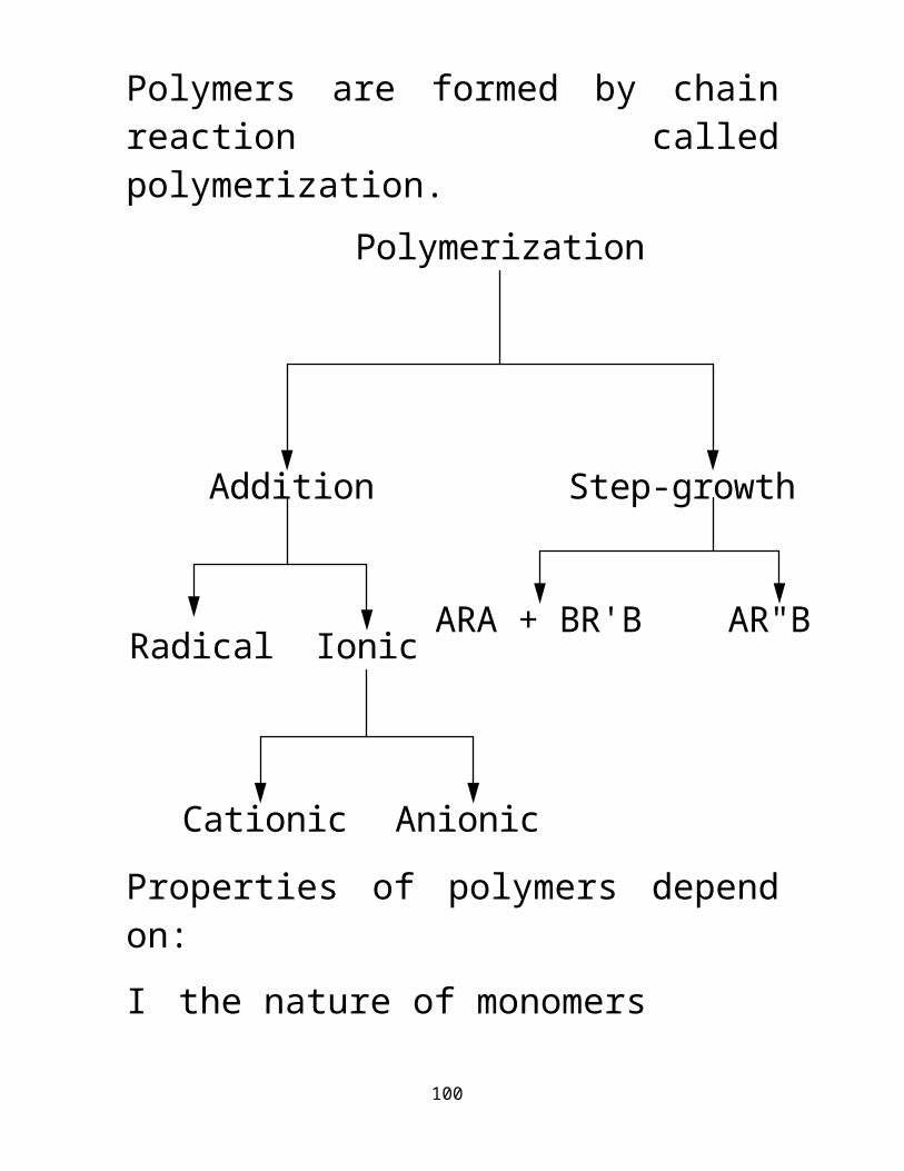
Polymers are formed by chain reaction called polymerization.
Polymerization
Step-growthAddition
Radical Ionic
Cationic Anionic
ARA + BR'B AR"B
Properties of polymers depend on:83

I the nature of monomersII the molecular weightIII temperature and timeADDITION POLYMERS They are formed by the addition of unsaturated monomers to the growing chain.Example of addition polymers include PE, PS, PMMA, PVC etc.
PolyethyleneEthylene
n
n C C
H H
HHH H
HH
CC
Generally
84

For PE, PS and PVC X = H, Ph and Clrespectively
XX
C C
H
HH H H
H
CCn
n
For a di-substituted monomer like methyl methacrylate;
n
n C C
H
HH
H
CC
X X
For PMMA, X and Y = Me and CO 2 Merespectively
Y Y
85

CONDENSATION POLYMERSCondensation polymerization results in the loss of small molecules such as water or methanol. Nylons and polyesters are good examples of condensation polymers.
Synthesis of a Typical Polyimide
86

NH2
(CH2)6NH2 CO2H
(CH2)4
CO2H
H
NH
(CH2)6
NH
CO
(CH2)4
CO
OH
Nylon 6,6
adipic acidhexamethylene diamine
+
n
Synthesis of a Typical polyester
87

HO (CH2)2 OH CO2H Ph CO2H
HO (CH2)2 O CO Ph CO O H
terephthalic acidethylene glycol
Poly(ethylene terephthalate)
+
n
CROSSLINKED POLYMERS
88

Crosslinked polymers are formed when the functionality of one of the reacting monomers is greater than two.Polymerization of styrene results in linear polystyrene. But when styrene is polymerized simultaneously with divinyl benzene, a crosslinked network system is obtained.Crosslinked polymers can also be formed by vulcanization and irradiation.
Representation of linear polymer
Representation of crosslinked network
89

H2C CH H2C CH
CH CH2
crosslinked polystyrene
divinyl benzenestyrene
90

Polymers are viscoelastic. Their properties are affected by temperature, environment and time (see table 2.8).Thermoplastics are either amorphous or semi-crystalline.Thermosetting polymers are amorphous.Amorphous polymers have only glass transition temperature, Tg.Semi-crystalline polymers have both glass transition temperature, Tg and melting temperature, Tm.Table 2.9 show the Tg and Tm of some polymers.Tg marked by a shift in the base line in the specific volume versus temperature plot (fig 2.3).
91

V
Temperature
high cooling rate
low cooling rate
T1 T2
3. Cooling and Heating Rates
92

V
Temperature
3. Cooling and Heating Rates
T3 T4
high heating ratelow heating rate
If the rate of cooling is faster than the rate of motion of the fastest segment the molecules would appear frozen in their lattices resulting in higher Tg.
93

Tm is marked by a break/discontinuity in the specific volume versus temperature curve (fig 2.3).The viscosity of polymers is considerably low above the Tg and Tm.Amorphous polymers are processed above Tg.Semi-crystalline polymers are processed above Tm.Significant changes in the mechanical properties of polymers occur at Tg and Tm.a. Modulus, strength, decrease at
Tgb. Polymer props are time/temp
dependent at Tg/TmMost polymers are used below Tg.
94

Semi-crystalline polymers PP, PE are used above Tg but below Tm.Highly cross-linked polymers can be used above their Tg.Thermoplastics are severely affected by strain rate and temp especially at Tg/Tm.Thermosets are less sensitive to temperature and strain rate Why?.Unlike metals and ceramics:Polymers absorb moisture;
epoxy/polyesters ~ 4-5% by weight
Polyamides 15-30% by weightPolymer becomes plasticized showing lowered mechanical properties.Common Polymer MatricesI Thermosetting Resins
95

Examples include polyesters, epoxy resins, bismaleimide resin, phenol formaldehyde resin, alkyd resin and polyimides.Characteristics of Thermosetting Resins:I. Easily processible.II. Good chemical resistance.III. Form 3-D networks. They are dimensionally stable.IV usually brittleV short pot lifeVI possibility of continued reaction for less than 100% cured system.VII cannot be reversibly processed
96

Polyester ResinThis is made up of unsaturated polyester.Unsaturated polyesters are formed by condensation reaction between ethylene glycol, propylene glycol, diethylene glycol and unsaturated dibasic acid (maleic or fumaric acid).
97

CH3 CH
OH
CH2
OHC C
CO2HHO2C
H H
CHCH2COOCHCHOCHO
CH3
Unsaturated polyester
Maleic acidPP glycol
II Dianhydrides
I Phthalic acid acts as spacer reduces the degree of crosslinking
Other reagents :
n
+
98

The polymer is dissolved in a liquid monomer and a peroxide/AZO initiator is added to form 3-D network.
CH2 CH
CHCH2COO
CHCH2COOCHCHOCHO
CH3
CHCHOCHO
CH3
CHCH2COOCHCH2OOC
CH3
CH2
CH
CHCH2COOCHCH2OOC
CH3
Curing of Unsaturated polyester
+ R•
n
n
99
The curing/crosslinking reaction occur at ambient or elevated temperatures. No bi-products are formed.* The degree of polymerization n varies ?The amount of monomer/styrene controls the viscosity and processibility of the resin. X-linking reaction gives no bi-productsX-linking reaction is exothermicX-linking results in shrinkage and rise in temperature.The properties of the polyester can be varied by varying the acids, glycols and monomers.Properties of thermosetting resins are given in table 2.10.
100

Epoxy ResinsEpoxy resins are low molecular weight liquid containing the oxirane (epoxide) group.Epoxy resin are produced from the reaction of epichlorohydrin and bisphenol-A.The viscosity of the resin depends on the degree of polymerization, n.The epoxy resin is reacted with a curing agent to form a 3-D network.Examples of curing agents includes diamines, anhydrides.
101

During curing reaction the epoxide ring is broken resulting in further polymerization.
Characteristics of Epoxy Cure Reactions
I exothermicII leads to shrinkageIII no bi-productsIV both room temp/high temp
curing of epoxy resin are possible.
102

H2C CHO
CH2 Cl HO C
CH3
CH3
OH
H2C CHO
CH2
H2C
O C
CH3
CH3
O
CHOH
CH2
OO C
CH3
CH3
O
If n = 1 ~ diglycidyl ether of BPA
n = 12
Epoxy resin
Bis-phenol A (BPA)Epichlorohydrin
-HCl
+
The properties of epoxy resin depend on the epoxy pre-polymer and the curing agent.
103

For higher temp resins use epoxidized novolac resin in place of EPH.Highly viscous at 25˚C.Flows slightly at 100˚C.Solvent = MEKLow temperature epoxies;
glycerolbis-phenol Fpentaerythritol
replace bisphenol A.Epoxy resins are cured by use of hardners;
Resin HardnersEpoxy 1o/2o aminesEpoxy Acids/
dianhydride104

Epoxy 30 aminesEpoxy resins are more moisture and chemical resistant than polyester resins.They also show better adhesion and wet the fibers better than polyesters.
105

PolyimidesThey have service temperature of about 250-300˚C.They are used where exceptional heat resistance is required.They are used in the manufacture of carbon or glass prepregs for laminating or filament winding.
Two types:I Those based on bis-maleimide
resin (Kerimid™) formed by addition polymerization
between a diamine and bismaleimide
II Polyimides based on cyclic anhydrides and diamines
106

Skybond-700™Prepared from cyclic anhydrides and amines/ammonia.Properties
I high strengthII good thermal / oxidative /
hydrolytic stabilityIII good molding compoundsIV good adhesion to fibers
PreparationPyromellitic dianhydride reacts with a 4,4'diaminophenyloxide to form polyamide acid which cyclizes at 120˚C to form polyimide.Water is released in the process.
107

Looses 1/3 of ambient tensile strength at 260˚C.Other PIs include duPont’s Kapton.Melts above 600˚C and shows zero weight loss at 500˚C in inert atm.
108

H2N O NH2C
OC
N OC
NC
CO
C
NH O NC
HO C
CH
C OH
CN
C
POLYAMIDE ACID
POLYIMIDE
-H2O120ÞC
O
O O
O
O
O O
O
Pyromellitic dianhydride4,4Diaminophenyloxide
dimethyl formamide25ÞC
O
OO
O
109

CN
CR N
C
CNH R NH
POLY(BISMALEIMIDE)
OO
OO
110

PolybenzimidazolesTg > 370 ˚C.Formed by the reaction between 3,3'-diaminobenzidene and diphenylisophthalate at 260˚C followed by vacuum at 400˚C.
111

H2N
H2N
NH2
NH2
OCO CO
O
CNH
N
NH
NC C
N
NH
Tg > 370ÞC
POLYBENZIMIDAZOLE
Diphenylisophthalate
3,3'Diaminobenzidene
n
112

II Thermoplastics
CharacteristicsI linear polymersII reversibly processibleIII possibility for large vol productionIV no further reaction needed after
polymer is formedV exceptionally toughnessVI long pot/storage lifeVI high melt viscosityVII poor dimensional stability
113

Properties of thermoplastics are dependent on:I the nature of monomersII the molecular weightIII amount of fillersIV temperature and time
Aromatic polymers have high Tg/Tm. They also have high strength and modulus. High molecular weight amorphous polymers have entanglements which act as physical cross-links.Crystalline thermoplastics are highly aligned and ordered.Heating of amorphous thermoplastics result in disentanglement and flow.
114

Heating of crystalline thermoplastics result in melting and flow.Thermoplastics can be oriented during processing.Crystalline plastics can be further oriented during thermal treatment and annealing.Examples of thermoplastics include PP, PE, PC, PET and nylons.Crystalline TP contain about 25-50% crystallinity. See properties of thermoplastics on a table elsewhere.Plastics yield and deform before fracture. Their properties are strongly dependent on temperature.Under constant loading conditions the strain increases with time i.e. they creep under loading conditions.Redistribution of load between resin and fibers occur during deformation.
115

Polypropylene (PP)PP is formed by Ziegler Natta polymerization in the presence of a Lewis acid, TiCl3 and co-reactant, AlR3 (Coordination polymerization).The rate of formation of PP is controlled by the rate of diffusion of monomer and polymer to and from the catalyst surface.Improve rate by agitation, controlling catalyst particle size and lower viscosity of the solvent.
116

TiCH2
AlR
CH3
CH2 CHCH3
Complex
POLYPROPYLENE
n CHCH3CH2
TiCl3 + AlR3
117

Nylon 6,6Tg ~ 50˚C, Tm ~ 265˚C, n ~ 35-45Formed by the condensation of hexamethylene diamine and adipic acid in the presence of methanol. Nylon salt is first formed and is heated in the presence of acetic acid at about 220-280˚C to form nylon 6,6.
118

H2N (CH2)6 NH2 HO-CO (CH2)4 CO-OH
H2N (CH2)6 NH3 O-CO (CH2)4 CO-OH
Ac NH (CH2)6 NH CO (CH2)4 CO
NYLON SALT
Adipic acid
diamineHexamethylene
NYLON 6,6
n
3 h220-280ÞCAcetic acid
-+
Methanol
119

PolyestersPoly(ethylene terephthalate) PETTg ~ 80˚C, Tm ~ 265 ˚CFormed from the reaction between ethylene glycol and therephthalate. This reaction takes place in two stages;
120

Stage IThe reactants are heated at 160-230˚C in the presence of a catalyst under nitrogen atmosphere to give the pre-polymer and methanol.The product is then heated at 260-300˚C in the presence of a catalyst under vacuum to give PET.HO (CH2)2 OH CH3 O-CO
HO (CH2)2 O-CO
CO-O CH3
HO (CH2)2 O-CO CO-O (CH2)2-OH
CO-O (CH2)2-OH
POLY(ETHYLENE TEREPHTHALATE)
Methyl terephthalateEthylene glycol
n
cat, vacuum260-300ÞC+ CH3OH
N2, catalyst160-230ÞC
+
121

MetalsPropertiesThey are high strength, high modulus, high toughness, high impact resistant and high temperature resistance.Compared to plastics metals are more thermally and environmentally resistant.Disadvantages of metal matrices include:
I Reaction with fibersII Corrosion
Metals used as matrix materials include;
Aluminum (2.7 g/cm3)Titanium (4.5 g/cm3)Aluminum/titanium alloys
122

Mg (1.7 g/cm3) reacts easily with O2 and is very corrosive.Ni and Co super alloys are also used as matrix materials at moderate temperatures.Oxidation of Ni/Co super alloys occur at elevated/high temperatures.See properties of metal matrices on table 2.14.Pure aluminum metal is corrosion resistant.Aluminum alloys 6061 & 2024 have high specific strength.Carbon is suitable fibers for Al matrix composites.But it reacts with Al at T ≥ 500˚C forming AlC which lowers the mechanical properties.
123

Coatings are applied onto fibers to prevent carbide formation and improve wetting/adhesion. Ti alloys used as matrices include Ti-6Al-9V and Ti-10V-2Fe-3Al.They have higher specific strength and retain properties at about 400-500˚C better than aluminum alloys.They react with boron and alumina fibers at processing temperatures.SiC and Borsic (boron fibers coated with silicon carbide) react less with Ti.
124

The InterfaceIn fibrous composites the fibers are separated from the matrix by the interface.The load applied to the matrix is transferred to the fibers through the interface.The stronger the interfacial bond the more efficient is the transfer of the applied load from the matrix to the fiber.
125

In the absence of any bonds, the composite has no strength along AA' (perpendicular).The strength and modulus along BB' depend on the grip.Consider two cases:A: Fiber stack gripped by means of
an adhesive bond.The strength of the stack depends upon the strength of the outer layer.
B: Fiber stack clamped;The clamped strength equals the strength of all the layers.In order to use the high strength and high modulus of fibers;The fibers must be strongly bonded to the matrix.
126

Lets consider a continuous unidirectional composite showing two major loading directions AA' and BB'.
Clamp
Adhesive bond
The Role of The Interface127

A
B'
A'
B
Cases 1. Perfect bond (100 % transfer)2. No bond (0 % transfer)3. % transfer depends on bonding4. Bonding improved by: (i) sizing coupling agents
128

Consider a continuous unidirectional composite showing two major loading directions AA' and BB'.
If no bond exists between the matrix and the fibers;Then composite has zero strength in AA'.
129

LV
SV LiquidVapor
SolidSLA
Contact angle for a liquid drop on a solid surface
Adhesion between two rigid rough surfaces
130

Adhesion and WettingIf two neutral surfaces are brought sufficiently close together they experience physical attraction.Consider the wetting of solid surfaces by liquids.When two solids are brought together, surface roughness on micro and atomic scale prevents surface contact.Most surfaces are usually contaminated. The liquid resin must cover all the hills and valley of the surface and displace trapped air.
131

The wetting of a solid by a liquid is explained by use of Dupree's equation:
WA
Where = surface energy,WA = the work of adhesionsub 1, 2 and 12 = liquid, solid and liquid-solid interface.From the Young's equation:
SV SLLV cos
Where;SV = solid-vapor interfaceSL = solid-liquid interfaceLV = liquid interface = the contact angle
132

Criteria for spontaneous wetting: = 0˚ of a solid measured by use of liquids of known .From Zisman's critical surface energy c;
LV cspontaneous wetting
LV cno wettingMaterial (mJ/m2)Glass 560Graphite 70Polyester 35Epoxy resin 43Polyethylene 31 (c)
Surface energies of some materials
133

Why can't either resin wet PE fiber ?.From Young's and Dupree's equation we obtain for WA:
WA SVLV SL
WA is the physical bond due to molecular dispersion forces.Why are strong physical bonds not formed b/n GF and resins.I contamination of fiber surfaceII presence of entrapped air and gases on fiber surfacesIII shrinkage of resin during cure
result cracks and flaws
Note that contamination reduces the surface energy of fibers.
134

Chemically reactive species called coupling agents are applied to the surface of the fibers.The bonding between the fibers and matrix is improved by use of chemical coupling agents.One end of coupling agent forms a bond with the fiber, the other forms bond with matrix.
The hydrolyzable ends react with water/fibers while the R-end reacts with the matrix.
135

R
SiO
M
R
Si
O
M
O
Coupling agent : Polysilane Representation : R-Si(X3) X = OH
INTERFACE
136

MeasurementConsider two linear elastic materials A and B.If the bond strength between A & B is less than the strength of A and B;Separation will occur.Lets the work done in creating two new surfaces WW = 1/2 F W =
The presence of cracks/flaws affects the performance of composites.
From Griffith’s theory:137

F E S
c
1/2
F
c1/2
sAB AB
Where E is the Young's modulus.Let one of the material be elastic while the other is plastic. And assume no flaws;The breaking stress (strength) is given by the relation:
F E S P
co 1/2
Experimental determination
138

Because of the different elastic properties of the matrix and fiber, the applied load is transferred by shear.The maximum tensile stress (strength) acting on the outer fibers at point 0 is given by the relation;
max 3 P S2 a2b
Where S is the span and a, b are the cross-sectional dimension of the specimen.
The ratio
max depends on test
geometry a
2 S.Tensile or flexural failure occurs at 0.
Shear failure depends on Sa ratio.
139

S is chosen such that failure occurs by shear.
L cc *F r
2 The solid is compressed along the fiber direction and shear is developed at the ends of fiber.
2.5 c = s
By measuring c at which de-bonding is first detected at the ends of fiber, we are able to estimate s.The extent of adhesion between the matrix and the fibers is measured also by the Interfacial shear test.
L cc *F r
2
Short beam shear test140

The unidirectional composite is tested in such a way that failure occurs in a shear mode parallel to fibers.The Inter-laminar shear test is a 3-point bending test.The shear stress t on the mid-plane xx' is related to the applied load P by the relationship:
3 P4 a b
Where a and b are the thickness and width of the specimen.
141

IFS Test
142

Interlaminar Shear Test
l
a
b
143

3 Composite TechnologyThe matrix and fiber are combined to form the composite.During composite formation, the matrix permeates, surrounds and wets the fibers.Fabrication TechniquesThermosetting matrix composites;
hand lay-upspray-upvacuum bag moldingcompression moldingRIM/RRIM
Final curing and shape forming occur in one stage. Why?Thermoplastic matrix composites;
injection molding, extrusion144

compression moldingTwo distinct steps: (1) matrix formation (2) shapingThermosetting Matrix CompositesPolymerization of the pre-poplymer and or monomer occur at the same time with cross-linking reaction in the presence of hardners/catalysts.
145

Classification
Wet process Premix/prepregOne-step curing & forming process
PDT formed while resin is fluidy
E.g. HLU, FW, BM, poltrusion
Two steps;a. Compoundingb. Curing under pressure & temp
E.g. SMC, BMC
146

Contact lay-up processAn open mold process.Well suited for low volume production and is less expensive.MaterialsmoldFibers ( GF mat, fabric, woven roven)Resin ( unsaturated polyester, epoxy)Additives ( curing agent)ProcedureMold is polished and coated with release agents such as PVA, wax, fluorocarbons, silicone, PTFE film.The resin, fiber and additives are fed into the mold.
147

Curing of the resin occur at ambient or elevated temperature.Hand lay up processMaterials:
moldcoatings, resin, additives, fibers
ProcedureThis process involves three stages of operation:I mold preparationFor good finish and stick-free molding.II gel coatingFor decorative and protective purposes.Gel-coat comprising the resin, pigments and mineral fillers are first applied to the mold and form the outer surface of the laminate.
148

III material preparationFor compounding of the materialsPre-measured resin and catalyst are thoroughly mixed.The resin mix is applied onto glass fibers (mat, cloth, woven roven) inside or outside the mold.Serrated rollers are used to compact the material and remove air bubbles.For SGF systemThe resin, catalyst and fibers are thoroughly mixed and fed into the mold.Sometimes surface mat or veil is coated on mold surface to improve finish.
149

Spray-up processChopped GF and resin are simultaneously deposited onto an open mold.Mixing occur externally or internally.External mixingTwo nozzles spray resin/catalyst and resin/accelerator onto mold.Internal mixing systemOne nozzle sprays the resin, catalyst and accelerator previously mixed in a single gun chamber.Advantages Disadvantages1 low cost labor intensive
150

2 design flexibility low volume3 production of long cure times
sandwich and much wastagecomplex parts absence of QC
Bag molding process (BMP)MaterialsMold,Resin, catalyst, hardenersFibersDiaphram/bagProcedurePlace fibers in the mold and coat/spray uniformly by resin.Cover mold with flexible diaphram/bag and seal diaphram.Connect vacuum line and slowly apply heat and pressure to cure.
151

Quality of molding depends on the molder.Thickness of the molding depends on the size of the oven/autoclave.Three types of BMP1) vacuum bag method2) pressure bag method3) autoclave method
AdvantagesI low costII vacuum bag can be used for
unlimited times.
152

Filament windingUses:Manufacture of surfaces of pipes, tubes, cylinder and spheres.Construction of large tanks.Continuous fiber rovings or prepregs may be used.Instrumentation;Creel, mandrelResin bath, sizing bathHeated ovenFeed; resin, catalyst; fiber roving
ProcedureFiber rovings are fed from multiplicity of creels, passed through sizing bath and resin bath, pre-cured in a heated oven.
153

The coated rovings are collected into a band of a given width and finally wound around a rotating mandrel.The fiber bands may be laid adjacent to each other over the length of mandrel.Winding angle and orientation of fibers is controlled by a specially designed machine that transverses and synchronizes with the rotating mandrel.Winding angle may be longitudinal, helical, circumferential or any combination of the above.Strength-performance requirements detect the winding angle.Advantages of filament wound vessels using prepregs/roving tapes1 less damage to fibers
154

2 A wide range of resin systems can be used
3 better control of Vm4 less messy operationAdvantages of filament winding1 Automation is possible2 very high strength parts can be
formed3 size of products can be easily varied4 anisotropy of properties can be
easily achievedDisadvantages of filament winding1 difficult to wind reverse curvatures2 difficult to wind at low angles3 difficult to obtain complex shapes4 poor finish/external surface
155

POLTRUSIONAutomated manufacture of continuous constant section profiles from composites is termed poltrusion.Poltrusion is well suited for thermosets that give no cure bi-products.Instrumentationcreelsresin bath (impregnator)heated diepuller/driving mechanismcut-off sawMaterials:resin (thermoset)fibers (continuous rovings/glass mat
156

ProcedureContinuous fiber rovings are pulled through the impregnator. They are then passed through the preforming fixture for shaping and removal of excess resin and cured in a heated die.
SMC/BMCThis is a continuous flat sheet of ready to mold composite.Materialsresin (unsaturated polyesters, epoxy)additives (hardners, inhibitors, mold release agent)fibers; 20-35 wt % of 21-55 mm long of
157

E-glass, S-2, carbon, Kevlar-49Both short and continuous fibers are used.ProcedureResin is mixed with catalyst and other additives to form resin paste.Fibers are added to the paste and the system is compacted.Finally SMC sheet are stored in a maturation room (temp controlled room) at 29-32˚C for 3 days.
AlternateCoat continuous PE/cellophane film with unsaturated polyester. Deposit a layer of chopped fibers onto the resin.Place a second layer of PE film and repeat the above procedure.
158

Pass the sandwich system through a series of compacting rollers and wind the sandwich into a roll.
BMCFormulation resemble SMCMaterialsfibers (15-20 wt% of 6-12 mm long E-glass fibers)resin (unsaturated polyesters)An intensive mixer is used to compound resin and fibers. The mixture is extruded as continuous
159

log and cut into desired length using a cutter.No thickners are used.PrepregsMaterialsresin (epoxy)additives (catalyst)fibers ( continuous/discontinuous)Equipmentresin bath, metering/compaction rollersProcedurePrepregs are produced from resin solution or hot melt.Fibers are passed through resin bath followed by the metering rollers.The coated fibers are pre-cured and rid of solvents in a heated section.
160

Cooled prepreg is sandwiched between two layers of silicone release film and wound into a roll or cut into sheets.
Banbury mixerout
entryram system
rotor bladecavity
rotor
core for heating and cooling
INTERNAL/BANBURY
Mixed materials is transfered to a 2-roll mill and sheeted out or they can be fed directly to the extruder.
161

NIP
HIDE
NIP
THE TWO ROLL MILL
162

Die Die adaptor
Filters
Barrel
Hopper
SCHEMATIC REPRESENTATION OF AN EXTRUDER
CHARACTERISTICS OF THE EXTRUDER
I Length to diameter ratioThe L/D ratio ranges from 12/1 upto 32/1The bigger the machine the bigger the L/D ratioII Compression ratioThis is an important characteristic of the extruder. It is defined as the volume contained in one complete turn of the screw at the feed end divided by the volume in one complete turn of the screw at the discharge end.
163

III Heating(i) External heaters: electrical heaters(ii) Shear: work done by the screws on the polymerConsiderable friction is generated between the polymer and the barrel surface and between the polymer and the screw surface.(iii) Heating can be done by running the extruder adiabatically at the risk of breaking the screw.
164

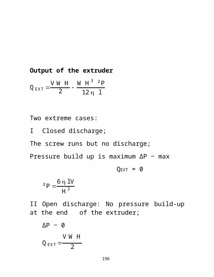
Output of the extruder
QEXT V W H2 W H 3 ² P
12 l
Two extreme cases:I Closed discharge;The screw runs but no discharge;Pressure build up is maximum ∆P ~ max
QEXT = 0
² P 6 l VH 2
II Open discharge: No pressure build-up at the end of the extruder;
∆P ~ 0
QEXT V W H
2
165

DIE
Increasing viscosity
Extruder
Increasing screw speed
Point of operation
QOUTPUT
Q MAX
²P ²P MAX
PERFORMANCE CHARACTERISTICS
166

EXTRUDER VOLUMETRIC EFFICIENCYThe ideal extruder output is obtained when the polymer melt flows with no rotation of screw;
Qideal Vdi X cross section of screw flight
Qideal š2 D2 H N tan
hevolumetric efficiency of the extruder is given by the ratio of the maximum flow rate to the ideal extruder flow rate;
Vol eff QmaxQideal
cos2
The volumetric flow rate depends on the helix angle and has a value of 45.4% for '.
167

WIRE COATING
The bare wire is pulled at a high speed m/s into the die at N and is coated on exiting the die at O. The melt flow is turned through a right angle and is separated into an annulus and extruded as a tube. Vacuum is drawn to enhance the movement of the melt onto the wire.
168

Molten plastic
Coated wireCore tube
Vacuum connector
Die body crosshead
Connecting bolt
Slight vacuum
Bare wire
ON
Die for wire coating
169

Moving moldFixed mold
Nozzle Screw
Sprue
A
B C
Operation of the injection molding machine
170
REACTION INJECTION MOLDING (RIM)
This is suited for large area moldings such as car bumpers and car body panels.RIM requires low injection pressure since the feed are low viscosity prepolymers and monomers. Low density aluminum molds are effectively substituted for steel, resulting in a significant weight savings and reduced cost.
Mold
Polyol + glass Isocyabate
Pump
Mixing head
Reaction injection molding
171

COMPRESSION MOLDING
Mold top part
Mold bottom part
Feed
172

COMPRESSION MOLDING
Mold top part
Mold bottom part
Feed Molding
173

Unidirectional CompositesIn unidirectional composites parallel fibers are embedded in a matrix. Several plys/lamina are stacked together forming a laminate.Unidirectional composites are orthotropic.Their properties are different in 3-mutually perpendicular directions at a point with 3-mutually perpendicular planes of symmetry.
174

3
2
1
Transverse
Longitudinal
Conversion of weight/volume fractionsUse density to convert from Wf to Vf
cfVf mVm : c1
Wff
Wmm
Wf Vf fc
: Wm Vm m
c
175

c theorycexp due to voids
Vv ct ce
ct
Density of void is determined in accordance with ASTM D2734-70Measured density of reinforced matrix is usually higher than the density of bulk resin resulting in lower Vv values.
176

Longitudinal Strength and ModulusInitial BehaviorAssumptions1 fibers are uniform and circular2 fibers are ideally packed and
aligned uni-axially
3 no contact between fibersideal dispersion and wetting
4 perfect bonding exist between fiber and matrix5 fiber and matrix are ideally elastic
The strain on fibers, matrix and composite are equal (iso -strain model)
177

Condition of stress equilibriumPc P f Pm : ccfA f mm
cfV f mVm IBy differentiation with respect to
dc
d d
dV f d
dVm
dd
is slope of Vs curve
Ec EfV f EmVm IIeqs I & II are the rule of mixture eqs.EX ICalculate Ec/Em for epoxy/E-glass and epoxy/carbon for Vf ~15% and Vf ~ 75%
178

Property increases as Vf is increased.Hence Ef influences Ec significantly.
0 1.0
Ef
Em
Vf
Plot of Ecl Vs Vf
179

Fiber
Matrixcomposite
f
cm
c
From the Vs diagram for fibers and matrixConsider two cases
i fiber has linear curve up to failurematrix also has linear
curveii fiber behave as in i
matrix has non-linear curve
180

At any given point obtain m/f, m/f and calculate cObservations
c linear in i ; c non-linear in iic/ curve lies b/n and m/curves
Vf c close to f curve
Vf Vm c close to m curve
Shearing of load b/n fiber and matrix in composite
fEf
mEm
cEc
fiber and matrix are linearly
elastic; fmc
181

fEf
mEm
cEc
fiber and matrix are linearly
elastic; fmc
f
m Ef
Em: and f
c Ef
Ec
Ratio of s similar to ratio of E.Ef must be >> Em for high c
P fPc
EfEm
EfEm
VmV f
182

Ef/Em
Pf/Pc x100
Vf
1
2
3
10050
Fiber load : load on Composite Vs Vf
% load on fiber increases as Ef/Em increases.Vf must be maximized for a given f/m system to ensure higher % fiber load.
183

Maximum Vf of cylindrical fibers in a composite ~ 91%.At Vf > 80% Pc decreases;Reasons;
I matrix cannot wet fibersII fibers are poorly bondedII presence of voidsIII fiber-fiber contact
Ex II: Estimate % of load on by fibers.
E-glass/epoxy system Vf = 15%, Ef = 70 GPa, Em = 3.5 GPa
184

Beyond initial deformationd/d = E under elastic deformationGenerally composite deform in four stages:
i fiber and matrix deform elastically
ii fiber deform elastically matrix deform plastically
iii fiber and matrix deform plastically
iv fiber fail followed by composite failureFor non-linear m/ curve
Ec EfV f Vmd m
d
c
Composite containing brittle fibers fail at f*.If f* < fc then fiber fail plastically.
185

Difference b/n f* and fc increases with Vf.Failure MechanismFor unidirectional composites under longitudinal loading;A composite starts to fail at f*Assumptions
i f* < m*ii all fibers have same f*iii Vf > Vmin ≥ 10% Composite fail instantly at f*cufuV f f*1 V f
186

If Vf < Vmin, matrix supports all loadand composite fail at m*.
cumu1 V f
V min mu mf*
f* mu mf*
Fig 3.7 plots eqs 3.23 and 3.24 Vs Vf
187

cu
Vf
Vcrit
Vmin
u
fu
mu
m)f*
f
cu of unidirectional composite Vs Vf
fu
mum)f*
f
188

Critical volume fraction VcritVcrit must be exceeded for strengthening to occur.Three cases;
i fiber controlled failurecufuV f f*1 V f
Vf ≥ Vminii matrix controlledcumu1 V f
Vf < Vminiii For reinforcement
cufuV f f*1 V f ≥ mu
Vf ≥ √crit
Vcrit mu mf*f mf*
189

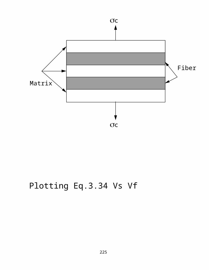
Transverse Stiffness and StrengthThe composite is made up of layers of matrix and fibers.Each layer is perpendicular to the loading direction.Each layer has same area, carry same load and experience same stress.
The mathematical model that fully describes this system is the Iso-stress model.
f = m = cThe elongation of the composite c in the direction of loading equals the sum of the fiber elongation and matrix elongation.
cfm
cctc; fftc; mmtm190

Assuming elastic deformation of the fibers and matrix;
c fVf mVm
1Ec
VfEf
VmEm
3.34
c
Matrix
Fibers
c
191

Plotting Eq.3.34 Vs Vf
Rule of mixture
Ec(T) eq. 3.34
Ec/Em
Vf
192

For Ef/Em = 10Vf ≥ 55 % in order for Ec(T) = 2 x Em Vf ≥ 11 % in order for Ec(L) = 2 x Em
Generally fibers do not contribute to higher E except at very high Vf.
Vf ≥ 90 % for Ec(T) ~ 5 x Em
Problems with the iso-stress model1. f ≠ m2. fiber and matrix shear applied load3. mismatch in poission ratio causes stress in fibers and matrix
perpendicular to the load.
193

Empirical EquationsHalpin-Tsai equations for Ec(T)
ETEM
1 Vf1 Vf
EfEm
1
EfEm
depends on fiber geometry, packing geometry, and loading conditions.For fibers with circular or square cross-sections, = 2.For rectangular cross-section fibers;
2 ab
194

Ec/Em
Vf
Ef/Em100
20105
Prediction of Halpin-Tsai equation
195
Ex IIICompare Ec(T) calculated using H-T equation with Ec(T) obtained by using the iso-stress model equation.Hint: Ef = 70 GPa, Em = 3.5 GPa, = 2.Two cases; i Vf = 10%
ii Vf = 50 %
196

r
r/a1 2 4
2 4 6
r
197

Stress distribution about a single fiber surrounded by the matrix
4%/6.88
55%/.39
78%/.012
max/av
Ef/Em
av
av
rr
198

Transverse StrengthWhen composites are stressed in transverse direction, the high E fibers constrain matrix failure there-by enhancing the Ec(T).Unlike Ec(L), Ec(T), c(L);— c(T) is lowered by the presence of fibers. and concentration in the matrix adjacent to the fibers.The composite usually fail at
cm*
199

Internal stresses and composite failureGoodier analyzed the stress in an elastic matrix surrounding single cylindrical fiber.See figure 3.12a for the variations in radial and tangential stresses.Near the inclusion r and >> The inclusion cause concentration in matrix (triaxiality of stresses).decreases rapidly for r/a =2r effects the failure up to r/a = 4
SCF max internal applied
200

We need to know m and SCF to calculate c*.A brittle matrix with inclusion fail at an applied stress lower than the fracture stress by a factor equals SCF.Factors affecting stress concentration in composites
i Vfii elastic properties of f and
matrix
201

Prediction of transverse strengthTwo approaches
i strength of material approachii advanced elasticity approach
Assumptions 1. The ultimate strength of composites U is controlled by matrix ultimate strength U
2. UU by a factor S; (SRF)S is fn of fiber and matrix properties, and Vf.
UMUS
uMUSMF
In case 1: S ~ SCF or SMF
202

SCF 1 Vf
1
EmEf
1 4Vfš
1/2
mEf
SMF 1
1 4Vfš
1/2
mEf
S can be calculated by use of the maximum disorientation energy Umax criteria.
S UMax1/2
c
Umax (Vf, fiber packing, Pf, Pm, interface)
According to NielsenCB V1/3
f For elastic matrix and fibers
CBM B
M1 V1/3
f
203

Transverse shear modulus1. The iso-stress model
fmccfmcctc e.t.cassume f and m are elasticGLT GfGm
GmV f GfVm
2. Halpin-Tsai modelGLTGm
1 V f1 V f
GfGm
1
GfGm
; 1
204

f m
fibers
matrix
fmc
Shear modulus for unidirectional composites
Shear deformations
205

Prediction of Poisson ratio
LTEL
TLET
LT fV f mVm
fibers
matrix
fmc
Prediction of Poisson's ratiof
m
L
206

Failure ModesFailure of composites occur in the following forms:
i internal failureii macroscopic failure
Forms of internal failure(a) fiber breakage(b) microcracking of matrix(c) fiber debonding(d) delamination
207

A ply or lamina fails when;Load on composite exceeds the linear elastic limitMax fracture load is attained
Non-linear failure curves may occur when;
i Vf << 1ii Em ≥ Ef (metal matrix
systems)
0
80
160
240
(%)
, KSI
Vf = 55%
Vf = 62%
1.2.8.40
graphite-epoxy
boron-epoxy
208

Longitudinal tensile failure3 modes of failure
i brittleii brittle with fiber
pulloutiii mode ii with (a) interface-matrix
shear failure(b)constituent
debonding For glass fiber composites;a brittle failure occur when Vf < 40%b brittle failure with pullout occur
when 0.4 < Vf < 0.65c at Vf > 65% brittle failure with
fiber pullout and debonding or matrix shear failure occur
209

Failure under compressive loadsContinuous fibers act as long columns resulting in microbuckling of fibers.At low Vf fiber microbuckling occur, but matrix strength is still elastic.At Vf > 40%, matrix yields or fiber debonds and matrix microcracks before microbuckling.
Longitudinal compressive failure of unidirectional composite occur;
when poission ratio effect >> cu.
Two effects;(i) crack is formed at interface(ii) shear failure
210

Failure modes of composites under longitudinal compressive loads(i) transverse tensile failure(ii) fiber microbuckling
a with matrix still elasticb after matrix failurec after constituent debonding
(iii) shear failure
211

A B
C
212

A— transverse tensile failure; microcracking and debonding
at interfaceB— occur at large fiber interdistance
adjacent fibers deform in out-of- phase manner to each other;
creates extensional strain in matrix (extension mode)
C— occur at Vf ≥ .65 deformation of adjacent fibers adjacent fibers deform in in-phase manner (shear mode);creates sharing strains in thematrix
According to Rosen:For shear mode buckling;
LU Gm1 V f
predicts lower at Vf 60%
213

If failure occurs at T (tensile strain) > composite breaking strain:
L'
LELC
: LT'
LELC
LTL
LU ' EfV f EmVm1 V1/3
f M U
V ff Vmm
where lT relates the longitudinal strength due to transverse strain (major Poission ratio)TL is the minor Poission ratio and relates the transverse strength to longitudinal strain.
214

Transverse tensile failureThe composite fail due to;
i matrix tensile failureii debonding or fiber splitting
Transverse compressive loadingThree modes of failure:
i matrix shearii matrix shear with debondingiii fiber crushing
215

Transverse tensile load
Transverse compressive load
216

In-plane shear failureModes of failure
i matrix shear failureii i with debondingiii debonding
In-plane shear failure
217

Thermal expansion coefficientRelates to changes in dimension due to changes in temperature. is defined as changes in the linear dimensions per unit length per unit change in temperature. is same in all directions for isotropic materials. for composites change with direction.Generally;
L 1EL
fEfV f mEmVm
T 1 ffV f 1 mmVm
LLT
T fV f 1 mmVm at V f>.25
218

Composite propertiesTensile
ELL
TET
Fibers Matrix Interface
SSWW
WWSS
NNNS
Composite props
Compressive
ELL
TET
Fibers Matrix Interface
SSWW
WSSS
NNNN
In-plane shear
GLTLT
Fibers Matrix Interface
WW
SS
NS
ILSS N S S
219

Discontinuous CompositesComposites composed of short fibers are termed short/discontinuous-fiber composites.The properties of these composites are dependent on the length of the fibers.
Undeformed
Deformed
Lines of equal strain
Continuous— uniform distribution of stress and strain in fiber/matrix
220

Undeformed
Deformed
Lines of equal strain
Discontinuous— non-uniform distribution of stress and strain. vary along fiber length
gradient
221

Conclusions based on the above model1. zero tensile stress at fiber ends2. max tensile stress at the fiber
center3. strain gradient develop from
outward surface of the matrix to the fiber surface
4. stress and strain gradient result in shear gradient at interface5. shear stress is max at fiber ends
shear stress is min at fiber centerTensile stress is therefore built into the fiber by shear transfer mechanism.
222

Stress/strain distribution along discontinuous fiber
223

Tensile force, PxShear stress
c
x
Px
x = l/2x = 0
Fiber length = l
Stress/strain distribution
is assumed constant and equals the shear strength of the interface i*.
224
Variation of Px with xdPxdx i r
dPx r xPr
r2 xr
fx 2ixr
x is linear distance from center
If x 0; fx 0If x l2; fx i*l
r
225

fx f* whenx lc
2 l2f* 2i* lc
r 2lcd f*
2 i*Where lc is the critical fiber length, d, (2r) is the fiber diameter.lc/d is the critical aspect ratio.
226

227

f
l
(lt/2)
l/2
lc/2
(f)max
f*
min
max
lt = elastic transfer length
If lt = lc (f)max = f*Occurs at fiber center
Progressive increase in stress transfer
228

f
l(l1 > lc)
(f)max
f*=
<f > <f > <f > <f >
(l2 = lc) (l3 < lc) (l4 < lc)
As l SFC resembles CFC
Assumption; const d; same matrix; const i*
cc f
Series of fibers of different length l
229

cc f
lc = (f* d) / 2 i*Efficiency of load transferIncrease efficiency by making lc small.
<>f f* 1
lc2l
How to increase efficiency(a) increase fiber length(b)reduce lc(c) increase i*
improve bonding b/n fiber and matrix
230

f*
Poorly bonded, low i* high lc
Strongly bonded,high i* low lc
EX IVConsider glass fiber reinforced nylon 6,6: f* = 3.5 GPa, d = 10-5 m, m* = 60 MPa.Calculate lc and l if <sf> = .95 f*Comparison b/n continuous and discontinuous composites
lcdisc
lccont
1 12
llc
1
m'f*
V f
1
231

Three casesl < lc
<> l *dl ≥ lc
<> f* 1 lc
2 l
l = ∞; lc/2l 0<f> f*
As the fibers become discontinuous end effects become more significant.
Note:
<f> f* 1 f d
4 *
* is associated with the shear strength of the matrix.For perfect bonding (i*= m*)
232

Prediction of strength
Uniaxially aligned short fibers of equal length l; (l lc)
(c)*disc (c)*cont
Fracture plane
Continuous fiber
233

Prediction of composite strength
lc*cont f*V f m'1 V f
lc*disc <f>V f m' 1 V f
(a) matrix/interface failurel < lc
<f> i* ld
(b)fiber failure at f* = fu
l > lc
<f> f* 1
lc2 l
(c) fiber failure at fu l >> lc
<f> f*
234

Prediction of composite modulusThe Halpin-Tsai Equations:(a) Longitudinal modulus
ELEm
1
2ld
L V f
1 L V f
ET
Em 1 2T V f
1 TV f
L EfEm
1
EfEm
2 ld
T EfEm
1
EfEm
2
235

Implications of H-T equations1 ET is not affected by l/d2. ET
disc ETcont
For composites containing randomly oriented fibers;
Erandom 38 EL 58 ET
Grandom 18 EL 14 ET
236

where G is the shear modulus, E is the Youngs modulus, subscripts L and T denote the longitudinal and transverse properties respectively.
Definition of a matrixA matrix is a rectangular array of elements.An array of M rows and N columns is a rectangular array of order [M, N].Square Matrices
237

M = NElements of a matrix aij = elements in the ith row and jth column.
[A] =
a11 a12 a13......a1n
a 21 a 22 a 23....a 2n
a m1 a m2................a mn
Matrix A
Special MatricesRow Matrices
[A] = a1 a2 a3......an
Matrix A
238

Column Matrix
[A] =
a1 a2 an
Matrix A
Transpose of A A T
Is a matrix obtained by interchanging all rows and columns.
239

[A] =
Matrix A
T
a11 a12 a13 a1n
a21 a31 am1
a2n amn
Symmetric square matrixAll aij aji
240

For this systemA A T
Diagonal matrixA square matrix where all but diagonal aij = o
[A] =
Matrix A
a11 0 0 0
0 amm
a22a33
0 0 0
Determinant of a square matrix
241

[D] =
Determinant D
a11 a21
amn
a 22
am1
a 12
The free index is not summed
D a11M11 a12M12 ... 1n1a1nM in
n >1
j1aijA ij
n >1
i 1aijA ij
Mij is the determinant of the order (n-1) formed by stricking out the jth row and the ith column. It is also called the minor of the element aij.
A ij Cofactor of aij 1ijM ij
242

a11 a21
[M] =
a 22
a 12Find D
[D] =
a 22
a 12a11 a21
[D] =
a 22
a 12a11 a21
a11M11 - a12M12
=;
a11a22 - a12 a21
Matrix operationAdditionOnly when [A] and [B] have same number of rows and columns.[A] + [B] = [C] and
243

aij + bij = cij
[C] = a11 a12
a21 a22
b11 b12
b21 b22+
(a11 + b11) (a12 + b12)
(a21 + b21) (a22 + b22)[C] =
Subtraction[A] - [B] = [C]aij - bij = cij
Matrix aljebraProduct of two matrices [C] = [A][B]True if;# of rows in [B] = # of columns in [A].
244

[C] = a11 a12 a13
a21 a22 a23
b11 b12
b21 b22a31 a32 a33 b31 b32
c11 (a11 b11+ a12b21 + a13 b31) (a11 b12+ a12b22 + a13 b32)
c12
c21 c22
(a21 b11+ a22b21 + a23 b31) (a21 b12+ a22b22 + a23 b32)
c31 c32
[A][B] = 1 00 0
0 2
1 0
EX VI. Find the product
245

The adjoint matrix of A is obtained by replacing each element of A by its cofactor and then transposing.
246

[A] =
1 1 1
2 3 5
3 5 12
Each element can be replaced by its cofactor
11 -9 1
-7 9 -2
2 -3 1
adj.A =
11 -7 2
-9 9 -3
1 -2 1
By transposing we obtain;
Inverse matrix of A is that matrix A-1 which satisfies the relation;
AA-1 = 1247

The inverse matrix can be determined from the identity;
A =-1 adj. A
|A|
248

If [A] =
1 1 1
2 3 5
3 5 12
adj.A =
11 -7 2
-9 9 -3
1 -2 1
If [A] =
|A| = det A =
1 1 1
2 3 5
3 5 12
= 1(11) - 2(7) + 3(2) = 3
A-1
= 2 -3
1
-2
1
113
-7 3
3
-9393
3
3
3
3
249

The inverse of a square matrix:A A 1 A 1A I
True for |D| ≠ 0
01
01
0
1
0
00AA = I = -1
e.g.
a11 a12
a21 a22[A] =
D = |A| = a11 a22 - a12 a21= a11 M11- a12 M21
Aij = (-1)i+j Mij
A12 = -M12 = -a21
A21 = -M21 = -a12
A11 = M11 = a22
A22 = M22 = a11
250

a11 a12
a21 a22[A] =
a22 -a12
-a21 a11
[A] =-1
; adj.A =
|A|=
a22 -a12
-a21 a11
(a22 a11 - a21 a12)
= 1
(a22 a11 - a21 a12)
a22 -a12
-a21 a11
[A][A] -1= [A] [A]-1 = [I] = 1
= 1
(a22 a11 - a21 a12)
a22 -a12
-a21 a11
a11 a12
a21 a22
Let n = (a22 a11 - a21 a12)
adj.A
251

[A][A] -1= [A] [A]-1 = [I]
a11 a12
a21 a22
= a22 -a12
-a21 a11
n n
nn
a22 a11 - a12 a21
a21 a11 + a11 a21n
nn
na22 a12 - a12 a22
a21 a12 + a11 a22n
nn
n
1
0
0
a22 a11 - a12 a21a22 a11 a12 a21-=
252

TensorsThese are mathematical models developed to describe physical conditions and phenomena., T and P are scalar quantitiesV, D, F, and are vectors. and are fully described by specifying the magnitude and two directions. Each component of signifies the magnitude of the average force component in one of the arbitrary fixed reference axes.For ij; each of the subscripts signifies a particular direction.ij; i & j = 1 or 2 in 2-Dijk; i, j & k = 1, 2 or 3 in 3-Dwhere 1 indicates direction of the normal and 2 represents the direction of the force component.
253

A tensor is defined as a mathematical or physical entity that transforms according to a specific law of transformation with a change in the coordinate system., T, P are tensors of zero order.
x3
x2
x1
333231
23
222113
1211
254

V, D, and F are first order tensors. and are second order tensors.Consider the figure belowFor a vector V;
x2' x2
V
x1'
x1
V1 V cos, V2 V sin
V1' V cos V cos cos V sin sinV2' V sin V sin cos Vcos sin i
255

By substitutionV1' V1 cos V2 sin IV2' V2 cos V1 sin IIV i' aji V j
Generally
Equations I & II are the laws for transforming components of a vector in one coordinate system to to those in another.
a11 cos11 cos a12 cos12 cos 90 sina21 cos21 cos 90 sina22 cos22 cos
Substituting into iV1' a11V1 a21V2
V2' a12V1 a22V2 III
256

V i' aji V j
Writing eq III as a matrix;
=a21 a22
a11 a12
V1 V2
V1' V2'
V1' V2'
= (aji)V1 V2
(aij) =a11 a21
a12 a22
=cos11 cos12
cos21 cos22
257

xi, i 1, 2, 3 3 1o tensoraij, i, j 1, 2, 3 9 stressbijk, i,j,k 1, 2, 3 27 strainEijkl, i,j,k,l 1,2,3 81 modulus
T = [ij] =
cos -sin
sin cos
0 0
0
01
first order tensor
To transpose multiply by the elements of the director cosine matrix
258

Let Vj =ij Vj'
V1' V2' V3'
cos -sin
sin cos
0 0
0
01
V1 V2 V3
=
V1 = V1' cosV2' sinV2 = V1' sinV2' cos
V3 = 00 V'3
Second order tensorsA ij ik jl A kl 9 dimensions
Plane stress case
259

[T] =
cos sin sincos
sin cos sincos
-sincossincoscos sin
2 2
2 2
2 2
cos sin sincos
sin cos sincos
sincos-incoscos sin
2 2
2 2
2 2
1 2 2
1' 2' 2'
=
A homogenous material is uniform at every point independent of position.
260

Isotropic material:— at any point properties are independent of orientation.Isotropic materials are not necessarily homogenous.Heterogenous material:— has non-uniform properties across the body.Properties vary with position (composites).Anisotropic materials— at any point the properties are a function of orientation.Properties are different in different directions.Homogenous materials may be anisotropic (graphite fibers, liquid crystals, and extended materials).Orthotropic material— at any point properties are a function of orientation but they have 3-
261

mutually perpendicular planes of material symmetry.Isotropic
1. Normal stress causes extension in direction of stress and contraction perpendicular to the stress.2. Shear stress causes only shear
deformation and deformation is related to tensile properties.
Orthotropic
262

1 Like in isotropic material normal stresses cause only extension in direction of stress and
contraction in direction perpendicular to it.2. Shear stress causes only shear
deformation but the shear deformation is not related to the tensile behavior.
AnisotropicA normal stress will cause extension, contraction and shear deformation.Off-axis loading of orthotropic materials result in anisotropic behavior.Samples are distorted when pulled making it difficult to measure properties.
263

Anisotropic
Orthotropic
264

Heterogenous isotropic
Heterogenous
a. isotropic if randomb. anisotropic if oriented
Orthotropicmirror images when rotated
265

ISOTROPIC ELASTIC SOLIDThese materials obey the Hooks law
ij Eij ij
At equilibrium;ij ji
Tensors Contracted notations
11
11
1
1
266

Stress Tensorsj Eij j; i,j 1.....6Eij Eji elements of stiffness matrix
1
1
E11 E61
E12- - - - E16 E66
E22E33
E44E55
=
267

i Sij j
Sij elements of the compliance matrix
1
S11 S61
S12- - - - S16 S66
S22S33
S44S55
1
=
Isotropic materialsE11 E22 E33
E13 E23 E12
E44 E55 E66
E66 E11 E122 ; all other ij 0
all other Eij 0Two independent variables
268

Writing the S in compliance matrix
1
S11 S12 S12
S12 S12
S11S11
2(S11-S12)
1
=2(S11-S12)
2(S11-S12)
000
0
S12S12
0
0
0000
00000
000
0
000
00
1 S111 S122 32 S112 S121 312 2S11 S1212
269

Evaluation of S11, S12Two tests— two independent variables
2 3 0
270

1
2 = 3 = 0
1 = S111 = 1
EL
2 = S121 = S12 1
S11
S12
S11
2
1= = S12 EL
= -(poisson ratio)S12
S11
=S11
=S12
1/EL
-EL
Shear Test
271

= EL
12
1 = 2 = 3 = 0
= GLT
= finite
12 = 2(S11 - S12)212
2(S11 - S12) 1 = GLT
RatiosEL
GLT
=2(S11 - S12)
S11 = 2(1-S12
S11)
2(1+ )
GLT2(1+ )=
272

Bulk modulus (compressibility)1/K = (volumetric strain)/(hydrostatic
pressure)
273

1K
=3 (S11 + 2S12) (1 + 2 + 3)
(1 + 2 + 3)
1K
= 1 + 2 + 3
1 + 2 + 3)
1K
=3EL
(1 -
K =EL
3(1-
If K and material is incompressible
= 1/2;
EL & GLT always +ve and
K is always +ve
Š 0.5; -1ŠŠ 0.5Experimentally Š 0.5
274

Plane stress3 0; 31 23 0
Stress Tensors1
S11 S12 0
S12
S111
=2(S11-S12)0
00
275

Engineering constants for ij matrix
1
E11 E12 0
E12
E221
=
E660 00
1 1E11 2E12
2 1E12 2E22
12
E22E12
1E12 E11
1 1E11 2E11
1 1E11 E111
1 E111 21 EL1
E11 EL
1 2; E12 EL
1 2
E66 G EL21
276

Strain measurement
L
L
=
1EL
EL
EL
1EL
1GLT
0
0
0 0
L LEL
TEL
T LEL
1 TEL
LT 1 LTGLT
Stress in terms of strain
L EL
1 2L EL
1 2T
T EL
1 2L EL
1 2T
LT GLT LT
277

UNIDIRECTIONAL LAMINA3
2
1
9 independent elastic constants
278
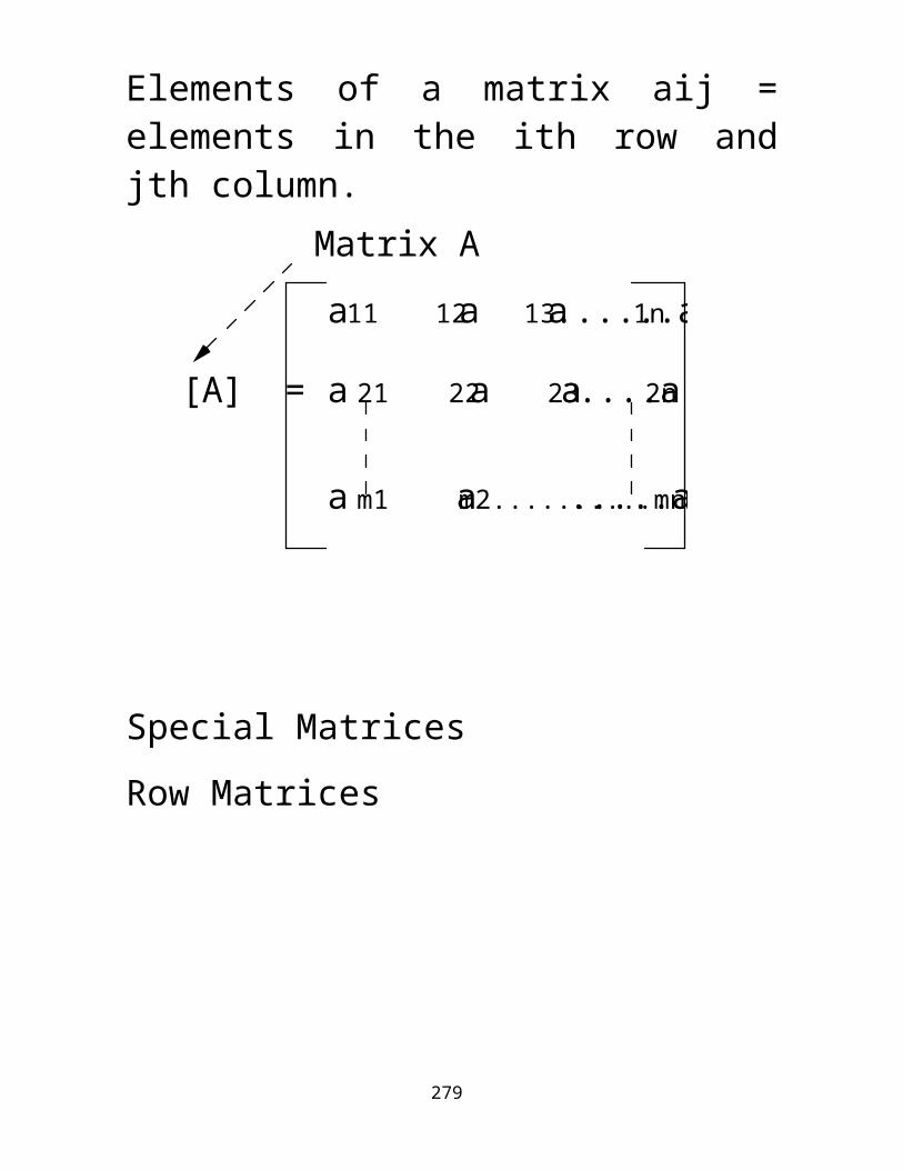
1
S11 S12 S13 0 0
S12 S13
S66
S22
S33S44
S55
1
=
000 0
0
000 0 0
0
00
0
00
S23
S23000
000
For plane stress
1
S11 S12 0
S12
S221
=
0 00
S66
3 = S13 S23
Constitutive equation for specially isotropic material.
Five independent elastic constants
279

1
Q11 Q12 0
1
= 00
Q66
Q12 Q22 0
TESTS Unidirectional tension
1
1
= 00
S66
S12 S22 0
S11 S12 0
1
1 S111 1EL
; 2 S121 S12EL
21
S12EL LT
S12 LTEL
280

To measure S22 do transverse test
S11 S12 0
S12
S221
=
0 00
S66
1 S122 S12ET2; 12
S12ET
2 S 222 2ET
; S22 1ET
;
12
LT ETEL
S12 ET TL
TL EL L T ET
Two poisson ratios in anisotropic material; LT ≠ TL
To measure S do shear test281

1 2 0; 12 S6612 12GLT
S66 1GLT
; LT ELETTL
EL, ET, GLT, LT, TL
Measured values of typical composites
Q11 EL1 LTTL; Q12 LTET
1 LTTL
Q22 ET1 LTTL
; Q66 GLT
Q16 Q26 0TL 0.1 0.15; LT 2 4
282

L
LT
L
LT
=
EL
1-LTLT
GLT0
0
0
0
LTET
1-LTL
LTET
1-LTL
ET
1-TLLT
Calculate L, T, LT
283

Transformation matrix
x y
xy
L
LT=
x y
xy
L
LT
=
[T]
[T]
yL
x
T
You must know the transformation matrix
1/2 1/2
284

Let m = cosn = sin
[T]n m nm
2nm -2nm m -n
m n -nm
2 2
2 2
2 2
=
[T]-1
=
-2nm 2nm m -n
m n nm
2 2
2n m nm
2
2 2-
L
LT
x y
xy
x y
xy=[T] [T]=
-1
;L
LT
-1
1/2 1/2
285

Introducing the identity matrix RL
LT
x y
xy
[T]=-1
-1
[Q] =L
LT[T]
-1[Q][R]
1/2
x y
xy
x y
xy[T]
-1[Q][R]
1/2
[T]=
x y
xy
x y
xy[T]
-1[Q][R]
1/2
[T]= [R]-1
[R] =1 0 0 0 1 0 0 0 2
[R] =1 0 0 0 1 0 0 0 1/2
286

=
x y
xy
x y
xy[T]
-1[Q][R]
1/2
[T]= [R]-1
= [Q]x y
xy
[Q]
Q11 Q12 Q16 Q12 Q22 Q26 Q16 Q26 Q66
Q 11 Q11cos4 2Q12Q66sin2cos2 Q22sin4
287

Uniaxial testing
x
y = 0
xy = 0
calculate x, y
and xy
n m nm
2nm -2nm m -n
m n -nm
2 2
2 2
2 2
L T
LT[T]=
x y
xy=
x
L m2x 0 0 cos2x
T n2x 0 0 sin2x
LT xsin cos
Calculate the principal stresses as a function of the angle and applied force.
288

L T
LT[S]=
L T
LT
Obtain expression of strains in terms of stresses.
By substitution
L xcos2
EL TL sin2
ET
T xsin
2ET
LTcos2EL
xsin cos
GLT
x y
xy[T]=
L T
LT
-1
1/2
In two steps
289

Alternatively calculate Q bar matrices first.
Ex xx
; Ey yy
; xy yx
yx xy EyEx
; Mx xyELx
My xy ELy
Mx measures the shear strain caused by normal stress sx.For isotropic material the only other properties left is GLT.
290

Strain Properties
xT
2
LT
xT
2
Theoriesmax stress theorymax strain theorymax energy theory
291

Theories for strain versus angle relationship.1. Max. stress theoryCalculate x, L, T, x, 1, 2
CriterionFracture occurs when a principal stress exceeds one of the following;
1 LU Tnsile or LU Comp
or 12 LTU or 2 TU Tensile or TU Comp
Which ever of these criteria is reached first is the criterion for failure.
1 x cos2; 2 x sin212 x sin2
292

To improve unidirectional stress you need to calculate all the other forces. The maximum allowable is x max.
xM ax xM ax Š L U
cos2 or
xM ax Š TU
sin2 or xM ax Š LU
sincos
Š TUsincos
293
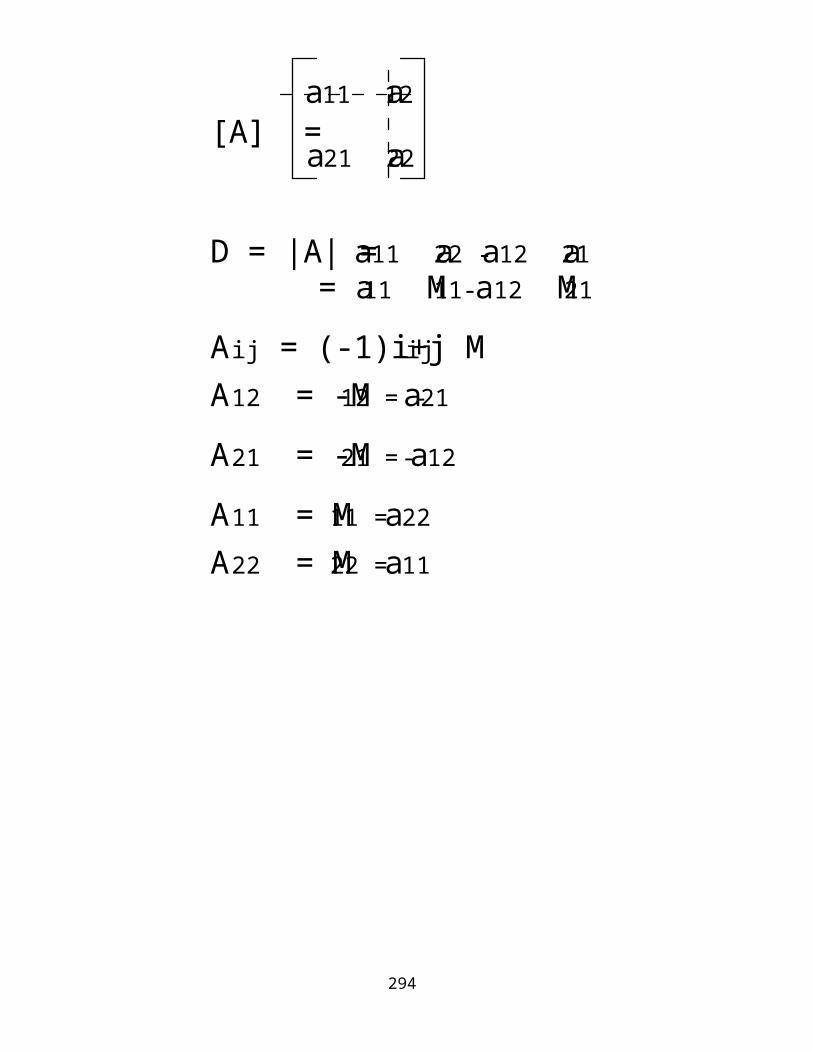
Lu
90
450
LUcos
(xmax
2LT TU
sin TU
Fiber breakage
294

B. Max Strain TheoryStates that the max allowable strain is the smallest of the following;
1max Š LU or 1max Š TU or12max Š LT
11E1
1 122 xEL
cos2 LTsin2
21E2
2 211 xET
sin2 TLcos2
12 12G12
xsin cos
295

Hill-Tsai Criteria.Energy criteria = Yield criteria.This criteria was originally designed for yield properties of materials but adapted by H-Tsai for composites.For plane stress state;
21
2LU
12
2LU
22
2TU
212
LTU 1
Resembles Von Misses criteria1 2
2 1 32 2 3
2 KGeneral form
1x
2max
cos4
2L U T
12
LTU 1
2L U T
cos2sin2
sin42
TU T
296

297