2-secm-03-67.pdf - freightliner trucks · ddec iii/iv single ecm troubleshooting guide 67.5.2 check...
TRANSCRIPT
67 FLASH CODE 67 - MAP SENSOR FAULT
Section Page
67.1 DESCRIPTION OF FLASH CODE 67 ..................................................... 67-3
67.2 SAE J1587 EQUIVALENT CODE FOR FLASH CODE 67 ....................... 67-3
67.3 TROUBLESHOOTING FLASH CODE 67 ................................................ 67-4
67.4 MAP INPUT VOLTAGE HIGH .................................................................. 67-5
67.5 MAP INPUT VOLTAGE LOW .................................................................... 67-12

(Rev. 2/03) All information subject to change without notice.
67-2 From Bulletin 2-SECM-03 6SE497 0207 Copyright © 2003 DETROIT DIESEL CORPORATION
DDEC III/IV SINGLE ECM TROUBLESHOOTING GUIDE
67.1 DESCRIPTION OF FLASH CODE 67
For diesel engines, Flash Code 67 indicates that the coolant pressure input voltage to the ECM hasexceeded or dropped below the allowed range.
This code is not covered in this manual (for diesel engines). If changes occur, notification willbe sent from DDC.
For gas engines, Flash Code 67 indicates that the input voltage to the ECM from the air inletpressure sensor has dropped below 5%, or gone above 95% of the sensor supply voltage.
67.2 SAE J1587 EQUIVALENT CODE FOR FLASH CODE 67
For diesel engines, the SAE J1587 equivalent codes for Flash Code 67 are 109/3, coolant pressuresensor input voltage high, and 109/4, coolant pressure sensor input voltage low.
For gas engines, the SAE J1587 equivalent codes for Flash Code 67 are p 106/3, air inlet pressuresensor input voltage high, and p 106/4, air inlet pressure sensor input voltage low. Inlet pressureis also referred to as Manifold Air Pressure (MAP).
All information subject to change without notice. (Rev. 2/03)
6SE497 0207 Copyright © 2003 DETROIT DIESEL CORPORATION From Bulletin 2-SECM-03 67-3
67.3 TROUBLESHOOTING FLASH CODE 67
67.3 TROUBLESHOOTING FLASH CODE 67
The following procedure will troubleshoot Flash Code 67.
67.3.1 Determine Failure
Perform the following steps to determine failure.
1. Turn ignition ON.
2. Plug in DDR.
3. Read codes.
[a] If code 106/3 is logged, refer to section 67.4, MAP Input Voltage High.
[b] If code 106/4 is logged, refer to section 67.5, MAP Input Voltage Low.
(Rev. 2/03) All information subject to change without notice.
67-4 From Bulletin 2-SECM-03 6SE497 0207 Copyright © 2003 DETROIT DIESEL CORPORATION
DDEC III/IV SINGLE ECM TROUBLESHOOTING GUIDE
67.4 MAP INPUT VOLTAGE HIGH
Follow these steps to troubleshoot manifold air pressure (MAP) input voltage high.
67.4.1 Sensor Check
Perform the following steps to check the sensor.
1. Turn vehicle ignition OFF.
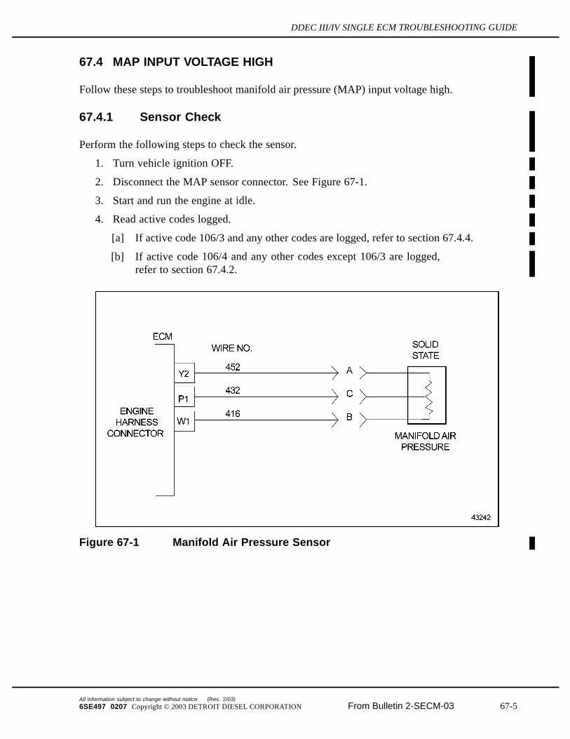
2. Disconnect the MAP sensor connector. See Figure 67-1.
3. Start and run the engine at idle.
4. Read active codes logged.
[a] If active code 106/3 and any other codes are logged, refer to section 67.4.4.
[b] If active code 106/4 and any other codes except 106/3 are logged,refer to section 67.4.2.
Figure 67-1 Manifold Air Pressure Sensor
All information subject to change without notice. (Rev. 2/03)
6SE497 0207 Copyright © 2003 DETROIT DIESEL CORPORATION From Bulletin 2-SECM-03 67-5
67.4 MAP INPUT VOLTAGE HIGH
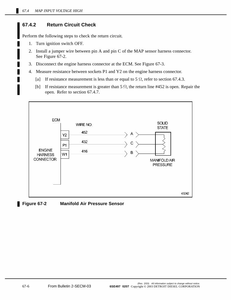
67.4.2 Return Circuit Check
Perform the following steps to check the return circuit.
1. Turn ignition switch OFF.
2. Install a jumper wire between pin A and pin C of the MAP sensor harness connector.See Figure 67-2.
3. Disconnect the engine harness connector at the ECM. See Figure 67-3.
4. Measure resistance between sockets P1 and Y2 on the engine harness connector.
[a] If resistance measurement is less than or equal to 5 , refer to section 67.4.3.
[b] If resistance measurement is greater than 5 , the return line #452 is open. Repair theopen. Refer to section 67.4.7.
Figure 67-2 Manifold Air Pressure Sensor
(Rev. 2/03) All information subject to change without notice.
67-6 From Bulletin 2-SECM-03 6SE497 0207 Copyright © 2003 DETROIT DIESEL CORPORATION
DDEC III/IV SINGLE ECM TROUBLESHOOTING GUIDE
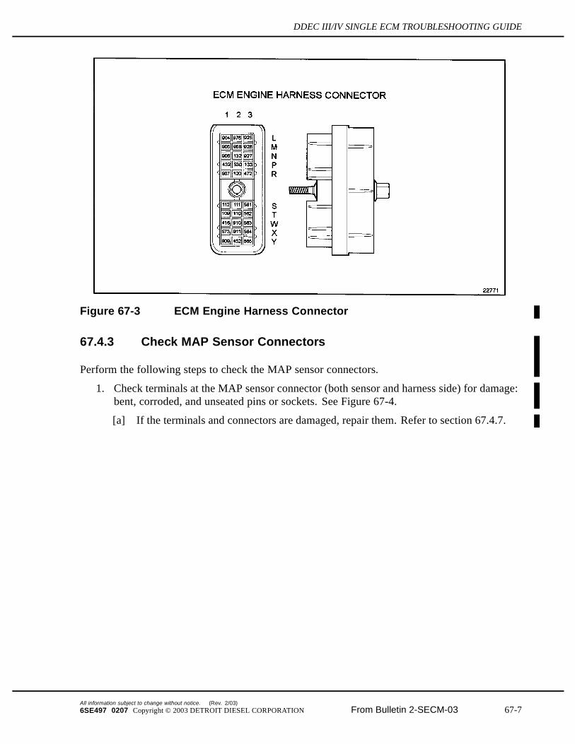
Figure 67-3 ECM Engine Harness Connector
67.4.3 Check MAP Sensor Connectors
Perform the following steps to check the MAP sensor connectors.
1. Check terminals at the MAP sensor connector (both sensor and harness side) for damage:bent, corroded, and unseated pins or sockets. See Figure 67-4.
[a] If the terminals and connectors are damaged, repair them. Refer to section 67.4.7.
All information subject to change without notice. (Rev. 2/03)
6SE497 0207 Copyright © 2003 DETROIT DIESEL CORPORATION From Bulletin 2-SECM-03 67-7
67.4 MAP INPUT VOLTAGE HIGH
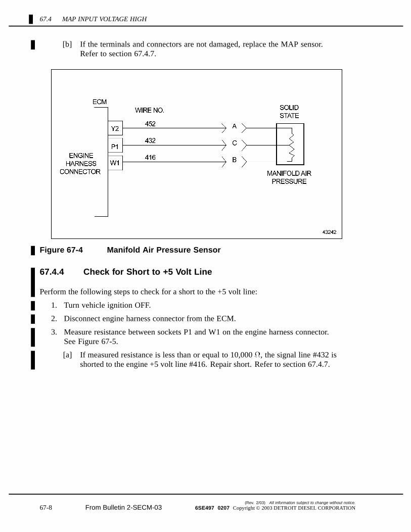
[b] If the terminals and connectors are not damaged, replace the MAP sensor.Refer to section 67.4.7.
Figure 67-4 Manifold Air Pressure Sensor
67.4.4 Check for Short to +5 Volt Line
Perform the following steps to check for a short to the +5 volt line:
1. Turn vehicle ignition OFF.
2. Disconnect engine harness connector from the ECM.
3. Measure resistance between sockets P1 and W1 on the engine harness connector.See Figure 67-5.
[a] If measured resistance is less than or equal to 10,000 , the signal line #432 isshorted to the engine +5 volt line #416. Repair short. Refer to section 67.4.7.
(Rev. 2/03) All information subject to change without notice.
67-8 From Bulletin 2-SECM-03 6SE497 0207 Copyright © 2003 DETROIT DIESEL CORPORATION
DDEC III/IV SINGLE ECM TROUBLESHOOTING GUIDE
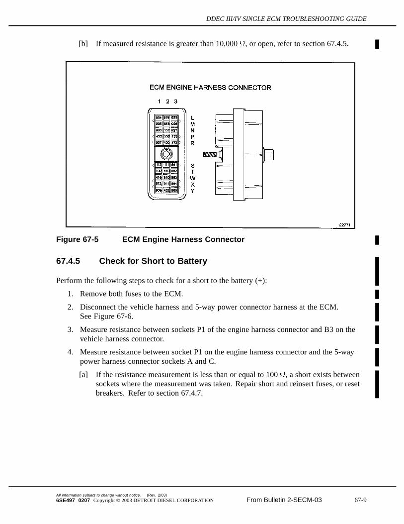
[b] If measured resistance is greater than 10,000 , or open, refer to section 67.4.5.
Figure 67-5 ECM Engine Harness Connector
67.4.5 Check for Short to Battery
Perform the following steps to check for a short to the battery (+):
1. Remove both fuses to the ECM.
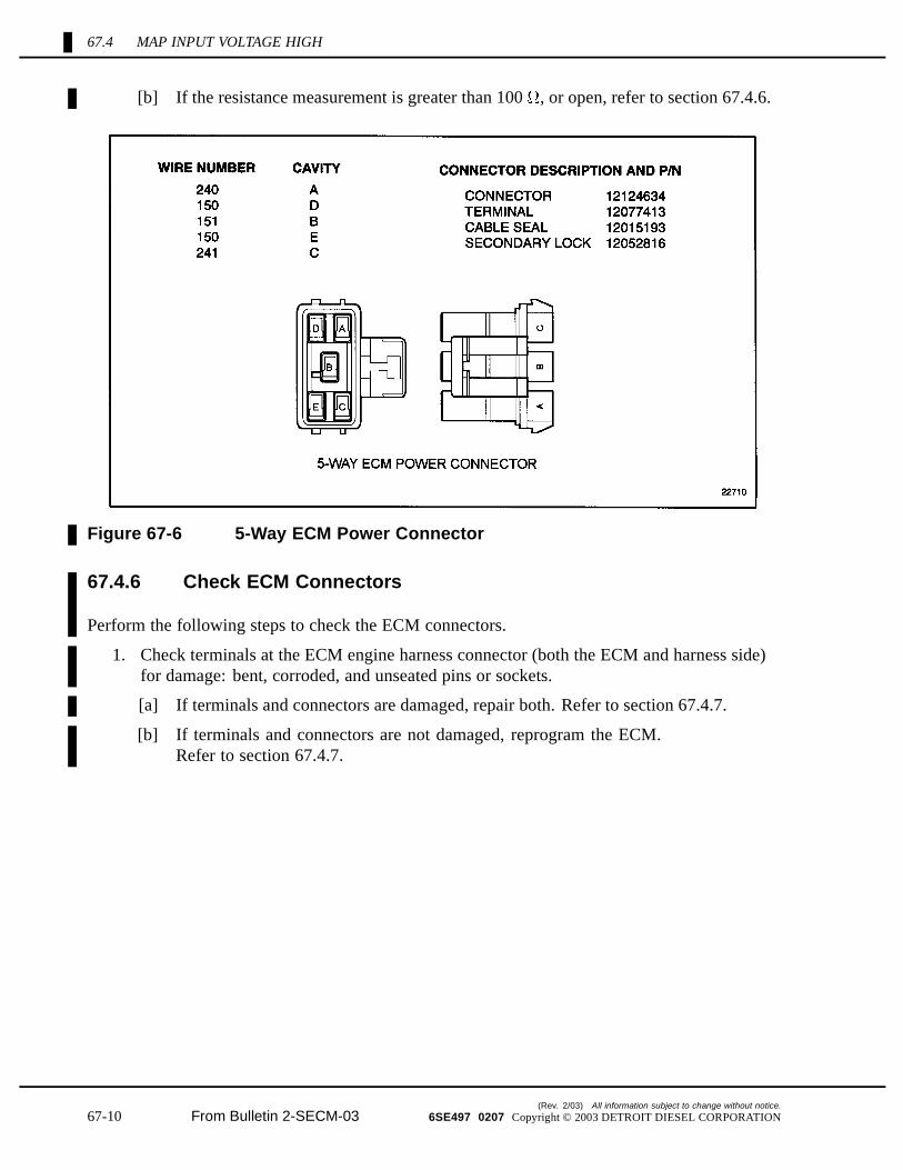
2. Disconnect the vehicle harness and 5-way power connector harness at the ECM.See Figure 67-6.
3. Measure resistance between sockets P1 of the engine harness connector and B3 on thevehicle harness connector.
4. Measure resistance between socket P1 on the engine harness connector and the 5-waypower harness connector sockets A and C.
[a] If the resistance measurement is less than or equal to 100 , a short exists betweensockets where the measurement was taken. Repair short and reinsert fuses, or resetbreakers. Refer to section 67.4.7.
All information subject to change without notice. (Rev. 2/03)
6SE497 0207 Copyright © 2003 DETROIT DIESEL CORPORATION From Bulletin 2-SECM-03 67-9
67.4 MAP INPUT VOLTAGE HIGH
[b] If the resistance measurement is greater than 100 , or open, refer to section 67.4.6.
Figure 67-6 5-Way ECM Power Connector
67.4.6 Check ECM Connectors
Perform the following steps to check the ECM connectors.
1. Check terminals at the ECM engine harness connector (both the ECM and harness side)for damage: bent, corroded, and unseated pins or sockets.
[a] If terminals and connectors are damaged, repair both. Refer to section 67.4.7.
[b] If terminals and connectors are not damaged, reprogram the ECM.Refer to section 67.4.7.
(Rev. 2/03) All information subject to change without notice.
67-10 From Bulletin 2-SECM-03 6SE497 0207 Copyright © 2003 DETROIT DIESEL CORPORATION
DDEC III/IV SINGLE ECM TROUBLESHOOTING GUIDE
67.4.7 Verify Repairs
Perform the following steps to verify repairs.
1. Turn ignition switch OFF.
2. Reconnect all connectors.
3. Turn ignition ON.
4. Clear codes.
5. Start and run the engine for one minute.
6. Stop engine.
7. Check DDR for codes.
[a] If no codes are logged, troubleshooting is complete.
[b] If code 106/3 is not logged, and other codes are logged, refer to section 9.1.
[c] If code 106/3 is logged, and other codes are logged, refer to section 67.4.1.
All information subject to change without notice. (Rev. 2/03)
6SE497 0207 Copyright © 2003 DETROIT DIESEL CORPORATION From Bulletin 2-SECM-03 67-11
67.5 MAP INPUT VOLTAGE LOW
67.5 MAP INPUT VOLTAGE LOW
Follow these steps to troubleshoot manifold air pressure (MAP) input voltage low.
67.5.1 Sensor Check
Perform the following steps to check the sensor.
1. Turn vehicle ignition OFF.
2. Disconnect the MAP sensor connector.
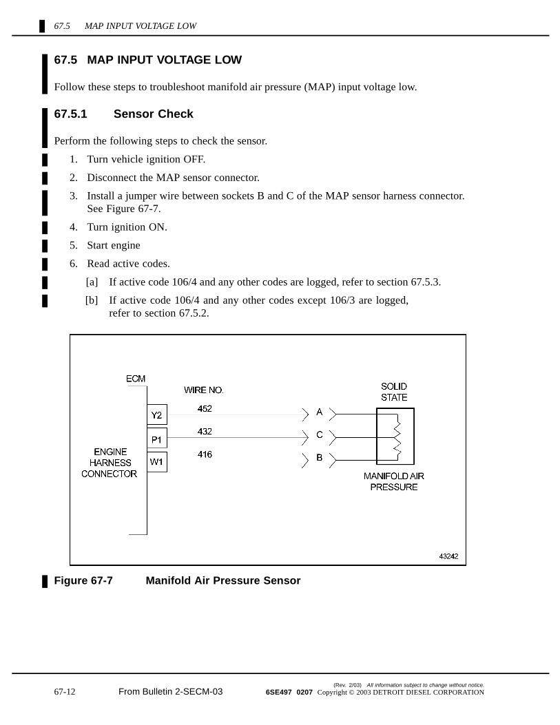
3. Install a jumper wire between sockets B and C of the MAP sensor harness connector.See Figure 67-7.
4. Turn ignition ON.
5. Start engine
6. Read active codes.
[a] If active code 106/4 and any other codes are logged, refer to section 67.5.3.
[b] If active code 106/4 and any other codes except 106/3 are logged,refer to section 67.5.2.
Figure 67-7 Manifold Air Pressure Sensor
(Rev. 2/03) All information subject to change without notice.
67-12 From Bulletin 2-SECM-03 6SE497 0207 Copyright © 2003 DETROIT DIESEL CORPORATION
DDEC III/IV SINGLE ECM TROUBLESHOOTING GUIDE
67.5.2 Check MAP Sensor Connectors
Perform the following steps to check the MAP sensor connector.
1. Check terminals at the MAP sensor connectors (both the MAP and harness side) fordamage: bent, corroded and unseated pins or sockets.
[a] If the terminals and connectors are damaged, repair them. Refer to section 67.5.10.
[b] If the terminals and connectors are not damaged, replace the MAP sensor.Refer to section 67.5.10.
67.5.3 Check for +5 Volt
Perform the following steps to check for +5 volt.
1. Remove jumper.
2. Turn ignition ON.
3. Measure voltage on MAP sensor harness connector, pin B (red lead) to pin A (black lead).
[a] If the voltage measurement is greater than 6 volts, refer to section 67.5.9.
[b] If the voltage measurement is between 4 and 6 volts, refer to section 67.5.4.
[c] If the voltage measurement is less than 4 volts, refer to section 67.5.7.
67.5.4 Check for Signal Open
Perform the following steps to check for signal open.
1. Turn vehicle ignition OFF.
2. Disconnect the engine harness connector at the ECM.
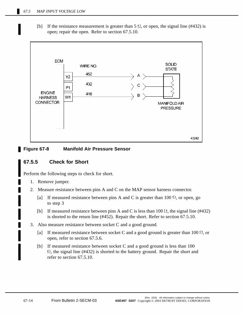
3. Install a jumper wire between pins A and C of the MAP sensor harness connector.See Figure 67-8.
4. Measure resistance between sockets P1 and Y2 on the engine harness connector.
[a] If the resistance measurement is less than or equal to 5 , refer to section 67.5.5.
All information subject to change without notice. (Rev. 2/03)
6SE497 0207 Copyright © 2003 DETROIT DIESEL CORPORATION From Bulletin 2-SECM-03 67-13
67.5 MAP INPUT VOLTAGE LOW
[b] If the resistance measurement is greater than 5 , or open, the signal line (#432) isopen; repair the open. Refer to section 67.5.10.
Figure 67-8 Manifold Air Pressure Sensor
67.5.5 Check for Short
Perform the following steps to check for short.
1. Remove jumper.
2. Measure resistance between pins A and C on the MAP sensor harness connector.
[a] If measured resistance between pins A and C is greater than 100 , or open, goto step 3
[b] If measured resistance between pins A and C is less than 100 , the signal line (#432)is shorted to the return line (#452). Repair the short. Refer to section 67.5.10.
3. Also measure resistance between socket C and a good ground.
[a] If measured resistance between socket C and a good ground is greater than 100 , oropen, refer to section 67.5.6.
[b] If measured resistance between socket C and a good ground is less than 100, the signal line (#432) is shorted to the battery ground. Repair the short and
refer to section 67.5.10.
(Rev. 2/03) All information subject to change without notice.
67-14 From Bulletin 2-SECM-03 6SE497 0207 Copyright © 2003 DETROIT DIESEL CORPORATION
DDEC III/IV SINGLE ECM TROUBLESHOOTING GUIDE
67.5.6 Check ECM Connectors
Perform the following steps to check the ECM connectors.
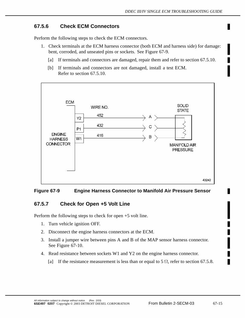
1. Check terminals at the ECM harness connector (both ECM and harness side) for damage:bent, corroded, and unseated pins or sockets. See Figure 67-9.
[a] If terminals and connectors are damaged, repair them and refer to section 67.5.10.
[b] If terminals and connectors are not damaged, install a test ECM.Refer to section 67.5.10.
Figure 67-9 Engine Harness Connector to Manifold Air Pressure Sensor
67.5.7 Check for Open +5 Volt Line
Perform the following steps to check for open +5 volt line.
1. Turn vehicle ignition OFF.
2. Disconnect the engine harness connectors at the ECM.
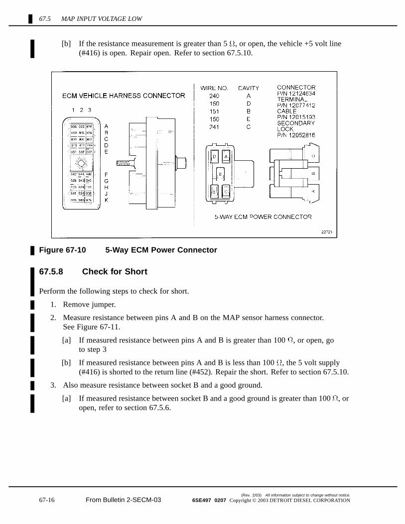
3. Install a jumper wire between pins A and B of the MAP sensor harness connector.See Figure 67-10.
4. Read resistance between sockets W1 and Y2 on the engine harness connector.
[a] If the resistance measurement is less than or equal to 5 , refer to section 67.5.8.
All information subject to change without notice. (Rev. 2/03)
6SE497 0207 Copyright © 2003 DETROIT DIESEL CORPORATION From Bulletin 2-SECM-03 67-15
67.5 MAP INPUT VOLTAGE LOW
[b] If the resistance measurement is greater than 5 , or open, the vehicle +5 volt line(#416) is open. Repair open. Refer to section 67.5.10.
Figure 67-10 5-Way ECM Power Connector
67.5.8 Check for Short
Perform the following steps to check for short.
1. Remove jumper.
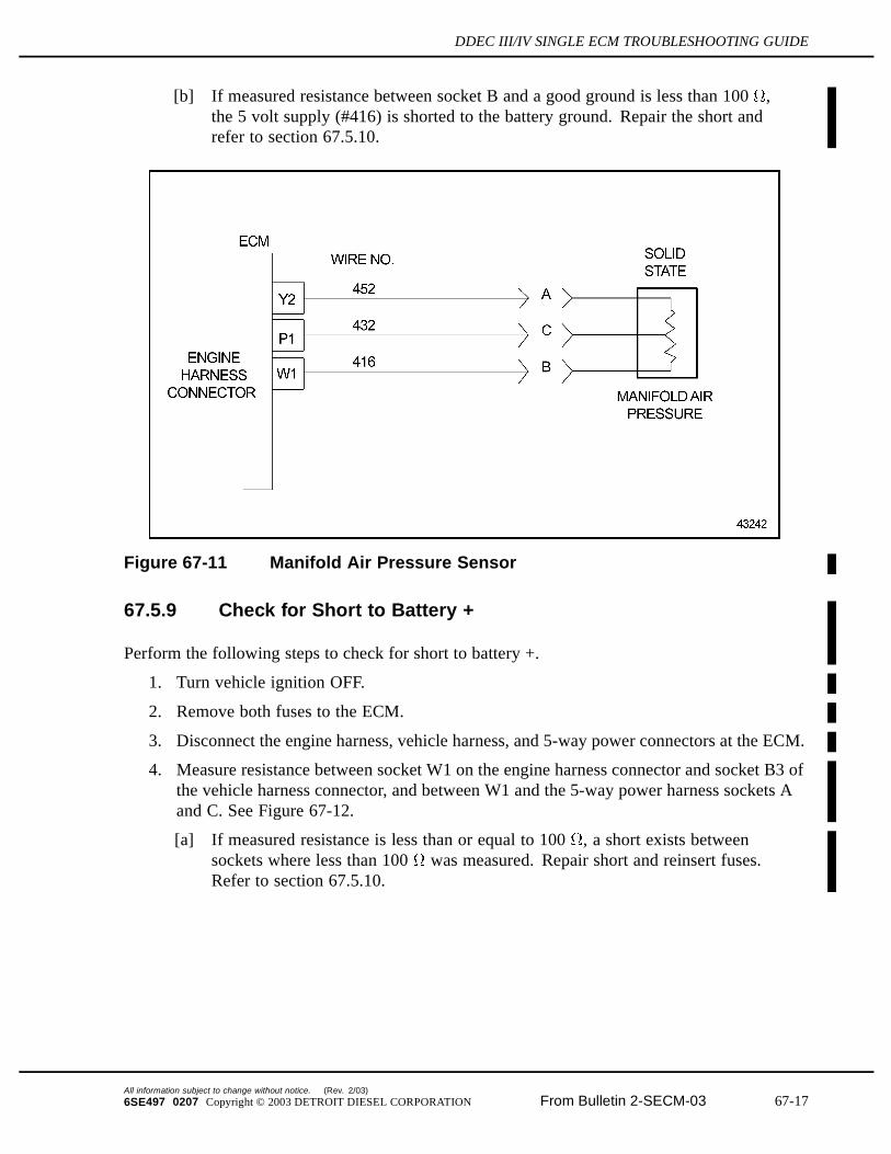
2. Measure resistance between pins A and B on the MAP sensor harness connector.See Figure 67-11.
[a] If measured resistance between pins A and B is greater than 100 , or open, goto step 3
[b] If measured resistance between pins A and B is less than 100 , the 5 volt supply(#416) is shorted to the return line (#452). Repair the short. Refer to section 67.5.10.
3. Also measure resistance between socket B and a good ground.
[a] If measured resistance between socket B and a good ground is greater than 100 , oropen, refer to section 67.5.6.
(Rev. 2/03) All information subject to change without notice.
67-16 From Bulletin 2-SECM-03 6SE497 0207 Copyright © 2003 DETROIT DIESEL CORPORATION
DDEC III/IV SINGLE ECM TROUBLESHOOTING GUIDE
[b] If measured resistance between socket B and a good ground is less than 100 ,the 5 volt supply (#416) is shorted to the battery ground. Repair the short andrefer to section 67.5.10.
Figure 67-11 Manifold Air Pressure Sensor
67.5.9 Check for Short to Battery +
Perform the following steps to check for short to battery +.
1. Turn vehicle ignition OFF.
2. Remove both fuses to the ECM.
3. Disconnect the engine harness, vehicle harness, and 5-way power connectors at the ECM.
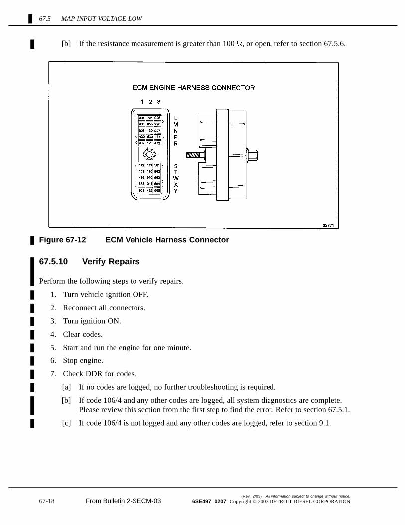
4. Measure resistance between socket W1 on the engine harness connector and socket B3 ofthe vehicle harness connector, and between W1 and the 5-way power harness sockets Aand C. See Figure 67-12.
[a] If measured resistance is less than or equal to 100 , a short exists betweensockets where less than 100 was measured. Repair short and reinsert fuses.Refer to section 67.5.10.
All information subject to change without notice. (Rev. 2/03)
6SE497 0207 Copyright © 2003 DETROIT DIESEL CORPORATION From Bulletin 2-SECM-03 67-17
67.5 MAP INPUT VOLTAGE LOW
[b] If the resistance measurement is greater than 100 , or open, refer to section 67.5.6.
Figure 67-12 ECM Vehicle Harness Connector
67.5.10 Verify Repairs
Perform the following steps to verify repairs.
1. Turn vehicle ignition OFF.
2. Reconnect all connectors.
3. Turn ignition ON.
4. Clear codes.
5. Start and run the engine for one minute.
6. Stop engine.
7. Check DDR for codes.
[a] If no codes are logged, no further troubleshooting is required.
[b] If code 106/4 and any other codes are logged, all system diagnostics are complete.Please review this section from the first step to find the error. Refer to section 67.5.1.
[c] If code 106/4 is not logged and any other codes are logged, refer to section 9.1.
(Rev. 2/03) All information subject to change without notice.
67-18 From Bulletin 2-SECM-03 6SE497 0207 Copyright © 2003 DETROIT DIESEL CORPORATION