2 - sdh alarms
DESCRIPTION
This ppt about SDH alarmsdifferent kind of alarms in sdhTRANSCRIPT
© Tejas Networks India Ltd., 2007, Proprietary Information Rev1.2 Last update 12 Dec 07 Reviewed by:
Tejas Networks
SDH Alarms

© Tejas Networks India Ltd., 2007, Proprietary Information Rev1.2 Last update 12 Dec 07 Reviewed by:
Organisation of Slides
SDH section hierarchy
SDH objects, nomenclature
Downstream and Upstream
Alarms understanding rules
RS alarms
MS alarms
HP / LP alarms
Description of Alarms
Alarm Masking and Suppressed Secondary Alarms
Alarm propagation examples

© Tejas Networks India Ltd., 2007, Proprietary Information Rev1.2 Last update 12 Dec 07 Reviewed by:
There are four sections – Regenerator Section (RS), Multiplex Section (MS), Higher
Order Path Section (HP), and Lower Order Path Section (LP)
RS is a part (section) of the optical fibre network, within which RSOH part of SDH frame is NOT opened
MS is a part (section) of the optical fibre network, within which MSOH part of SDH frame is NOT opened
HP is a part (section) of the optical fibre network, within which higher order VC part of SDH frame is NOT opened (it may be opened only for interpreting HOPOH)
LP is a part (section) of the optical fibre network, within which lower order VC part of SDH frame is NOT opened (it may be opened only for interpreting LOPOH)
SDH Section Hierarchy

© Tejas Networks India Ltd., 2007, Proprietary Information Rev1.2 Last update 12 Dec 07 Reviewed by:
SDH Section Hierarchy (…contd.)
Points to Remember:
Without opening RS, one can not do operation with MS and/or open MS Without opening MS, one can not do operation with HP and/or open HP Without opening HP, one can not do operation with LP and/or open LP
Consequences
• So, for Tejas nodes, even if one is making a VC4 level pass-through (an operation with HP without opening it), he/she is opening MS & therefore terminating the MS
• One can change any HPOH field (e.g., J1 transmitted trace) only when one is opening HP (e.g., VC12 level cross-connect exists on AU4 mapping), but not when HP is not disturbed (e.g., VC4 level pass-through on AU4 mapping)
Points to Remember:
For Tejas nodes, for AU4 mapping, one can make VC4 and VC12/VC11 level and not VC3 level pass-through for E1/DS1 traffic
Consequences
• If in a STM-1 node, multiple (say, 18) E1/DS1 traffic have to be passed-through with some other traffic added/dropped from that node, one has to make multiple (18) VC12 level pass-through

© Tejas Networks India Ltd., 2007, Proprietary Information Rev1.2 Last update 12 Dec 07 Reviewed by:
Section Hierarchy (examples)
Example 1
Example 2
ADM 1 ADM 2
Reg.
MS
RS RS
ADM 1 ADM 2 ADM 3
RSRS
MSMS (STM 1)
(VC4)
© Tejas Networks India Ltd., 2007, Proprietary Information Rev1.2 Last update 12 Dec 07 Reviewed by:
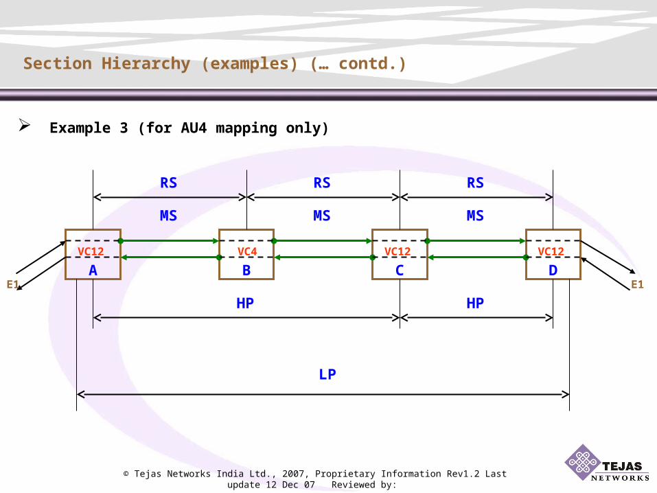
Example 3 (for AU4 mapping only)
Section Hierarchy (examples) (… contd.)
DA B CVC12 VC12
E1 E1
VC12 VC4
RS
MS
RS RS
MS MS
HPHP
LP

© Tejas Networks India Ltd., 2007, Proprietary Information Rev1.2 Last update 12 Dec 07 Reviewed by:
Section Hierarchy (examples) (… contd.)
Example 4a (for STM1 capacity & AU4 mapping only)
H
A B
C
D
E
F
G
#1 E1 – between A & E
#2 E1 – between F & H
E3 – between F & G
E1
E1VC12VC12
E1
E1
VC
12
VC
12
E3
E3 VC
3
VC
3
Reg.
RS – A-B, B-C, C-D, D-E, F-B, C-G, E-H
MS – A-B, B-C, C-E, F-B, C-G, E-H
HP – A-B, B-C, C-E
LP – A-E
HP – F-B, B-C, C-G
LP – F-G
HP – F-B, B-C, C-E, E-H
LP – F-H

© Tejas Networks India Ltd., 2007, Proprietary Information Rev1.2 Last update 12 Dec 07 Reviewed by:
Section Hierarchy (examples) (… contd.)
Example 4b (for STM4 capacity & AU4 mapping only)
H
A B
C
D
E
F
G
#1 E1 – between A & E
#2 E1 – between F & H
E3 – between F & G
E1
E1VC12VC12
E1
E1
VC
12
VC
12
E3
E3 VC
3
VC
3
STM # 1
STM # 2
----- VC 4
Reg.
STM # 2
Within STM # 1
STM # 1
RS – A-B, B-C, C-D, D-E, F-B, C-G, E-H
MS – A-B, B-C, C-E, F-B, C-G, E-H
HP – A-E
LP – A-E
HP – F-C, C-H
LP – F-H
HP – F-C, C-G
LP – F-G

© Tejas Networks India Ltd., 2007, Proprietary Information Rev1.2 Last update 12 Dec 07 Reviewed by:
SDH objects, nomenclature
3 different kinds of objects:
• STM port (STM-1 / STM-4 / STM-16)
• AU (AU-3 / AU-4 / AU-4-4c / AU-4-16c) – Higher-order object (present even if no HO cross-connect)
• TU (TU-11 / TU-12 / TU-2 / TU-3) – Lower-order object (present only if LO cross-connect exists) Nomenclature
• STM-1 chassis – slot – port (these fields are product specific)
• AU-4 chassis – slot – port – STM # – 1• AU-3 chassis – slot – port – STM # – K (for AU-3 mapping)
• TU-3 chassis – slot – port – STM # – K (for AU-4 mapping)• TU-2 chassis – slot – port – STM # – K – L• TU-12 chassis – slot – port – STM # – K – L – M (M = 1 to 3)• TU-11 chassis – slot – port – STM # – K – L – M (M = 1 to 4)
Note: STM # = 1 (for STM-1) = 1 to 4 (for STM-4) like that, K = 1 to 3, L = 1 to 7

© Tejas Networks India Ltd., 2007, Proprietary Information Rev1.2 Last update 12 Dec 07 Reviewed by:
Downstream & Upstream
Downstream direction for a fault condition
Along the direction of fault condition received OR Towards the Back-plane of the node receiving fault condition
Upstream direction for a fault condition
Opposite of the direction of fault condition received OR Away from the Back-plane of the node receiving fault condition
Downstream & Upstream direction for a node not fixed
Depends on direction of fault condition (abbreviated as FC)
ADM 1 ADM 2 ADM 3
FC 1
Downstream
Upstream
FC 2
Upstream
Downstream

© Tejas Networks India Ltd., 2007, Proprietary Information Rev1.2 Last update 12 Dec 07 Reviewed by:
Alarm Understanding Rules
Rule 1
Rule 2
FC 1Alarm reported
Alarm reportedFC 1
ADM 1 ADM 2
ex. a
ADM 1 ADM 2
ex. b
Alarms reported are alarms received
Alarms are reported on SDH Objects

© Tejas Networks India Ltd., 2007, Proprietary Information Rev1.2 Last update 12 Dec 07 Reviewed by:
Alarm Understanding Rules (…contd.)
Rule 3
ADM 1 ADM 2
ex.
3a. No Object => No Alarms reported
FC on TU12 (1-1-1)
NO TU12
(1-1-1)
3b. Object Mismatch => No Alarms reported
FC on TU12 (1-1-1)
TU11
(1-1-1)
ADM 1 ADM 2
ex.
Note:
These two examples are not possible for AU object
WHY?
See slide 9
NO Alarm reported for FC on TU12 (1-1-1)
NO Alarm reported for FC on TU12 (1-1-1)

© Tejas Networks India Ltd., 2007, Proprietary Information Rev1.2 Last update 12 Dec 07 Reviewed by:
Alarm Understanding Rules (…contd.)
Rule 4
4a. No PT XC => No Alarms pass-through
FC on AU4 (1)
NO VC4
PT (1)
Alarm reported for FC on AU4 (1)
FC on TU12 (1-1-1)
ADM 1 ADM 2 ADM 3
ex. a
ADM 1 ADM 2 ADM 3
ex. b
NO Alarm pass-through
NO VC12
PT (1-1-1)
NO Alarm pass-through
NO Alarm reported for FC on TU12 (1-1-1)

© Tejas Networks India Ltd., 2007, Proprietary Information Rev1.2 Last update 12 Dec 07 Reviewed by:
Alarm Understanding Rules (…contd.)
4b. Bigger PT XC => No Alarms reported & Alarm pass-through
FC on TU12 (1-1-1)
Alarm pass-through for
FC on TU12 (1-1-1)
NO Alarm reported
for FC on TU3 (1)
VC4
ADM 1 ADM 2 ADM 3
ex. aSTM-1
links
4c. Smaller PT XC => No Alarms reported (always ??) & Alarm pass-through but on smaller object
FC on TU3 (1)
VC12
(1-1-1)
NO Alarm reported
for FC on TU12 (1-1-1)
ADM 1 ADM 2 ADM 3
ex. bSTM-1
links
Alarm pass-through for
FC on TU12 (1-1-1)What if Same size PT XC ?

© Tejas Networks India Ltd., 2007, Proprietary Information Rev1.2 Last update 12 Dec 07 Reviewed by:
RS Alarms
RS alarms are those, which can be reported even by a pure Regenerator
(who has privilege of opening (interpreting & rewriting) only RSOH)
LOS (Loss of Signal)based on whole RSOH
LOF (Loss of Frame)based on A1, A2 bytes
TIM (Trace Identifier Mismatch)based on J0 byte
SF (Signal Fail)based on B1 byte
SD (Signal Degrade)based on B1 byte
D3D2D1
F1E1B1
J0A2A1
RSOH bytes
Note: The order in which the alarms are written is important,
as we will see later while discussing Alarm masking

© Tejas Networks India Ltd., 2007, Proprietary Information Rev1.2 Last update 12 Dec 07 Reviewed by:
MS Alarms
MS alarms are those, which can be reported by a Add-Drop Multiplexer, irrespective of cross-connect configuration
(who has privilege of opening (interpreting & rewriting) RSOH, MSOH, AU pointers plus opening HOPOH(s) / TU Pointers / LOPOH(s) depending upon cross-connect configuration)
AIS (Alarm Indication Signal) reported based on K2 byte -- bits 6,7,8
SF (Signal Fail)based on B2 bytes
SD (Signal Degrade)based on B2 bytes
RDI (Remote Defect Indication)based on K2 byte -- bits 6,7,8
MSOH bytes
K2K1B2
D6D5D4
D9D8D7
E2M1S1
D12D11D10
Note 1: The order in which the alarms are written is important, we will see later while discussing Alarm masking
Note 2: MS-AIS is also called Line-AIS or AIS on STM port
MS-RDI is also called Line-RDI or RDI on STM port

© Tejas Networks India Ltd., 2007, Proprietary Information Rev1.2 Last update 12 Dec 07 Reviewed by:
HP / LP Alarms
HP / LP alarms are those, which can be reported by a Add-Drop Multiplexer, having HO / HO & LO object (LO object => LO cross-connect)
(who has privilege of “opening (interpreting & rewriting) RSOH, MSOH, AU Pointers plus at least interpreting HOPOH(s)” / “opening (interpreting & rewriting) RSOH, MSOH, AU Pointers, HOPOH(s), TU Pointers plus at least interpreting LOPOH(s)” depending upon cross-connect configuration)
HP-AIS reported based on H1, H2 bytes
HP-LOP (Loss of Pointer) based on H1, H2 bytes
HP-UNEQ (unequipped) based on C2 byte
HP-TIM based on J1 byte
HP-SF based on B3 byte
HP-SD based on B3 byte
HP-RDI based on G1 byte -- bit 5
Note 1: Same as before
Note 2: HP-Alarm is also
called AU-Alarm
or Alarm on AU
LP-Alarm is also
called TU-Alarm
or Alarm on TU
K3F3
H4
F2
G1
C2
B3
J1
N1
HOPOH
bytes
H1, H2, H3 – AU Pointer bytes

© Tejas Networks India Ltd., 2007, Proprietary Information Rev1.2 Last update 12 Dec 07 Reviewed by:
HP / LP Alarms (…contd.)
LP-AIS reported based on V1, V2 bytes
LP-LOP based on V1, V2 bytes
LOM (Loss of Multiframe) based on H4 byte – bits 7,8
HP-PLM / SLM (Payload / Signal Label Mismatch)based on C2 byte
LP-UNEQ based on V5 byte – bits 5,6,7
LP-TIM based on J2 byte
LP-SF based on V5 byte – bits 1,2
LP-SD based on V5 byte – bits 1,2
LP-RDI based on V5 byte -- bit 8
LP-PLM / SLM based on V5 byte – bits 5,6,7
Note 1: Same as before
Note 2: Whole of this slide assumes
TU2/TU12/TU11 for LP. If there
is TU3 with AU4 mapping, then
also it is LP but Pointers & POH
bytes will be like HO
K4
N2
J2
V5
LOPOH bytes
V1, V2, V3 – TU Pointer bytes
© Tejas Networks India Ltd., 2007, Proprietary Information Rev1.2 Last update 12 Dec 07 Reviewed by:
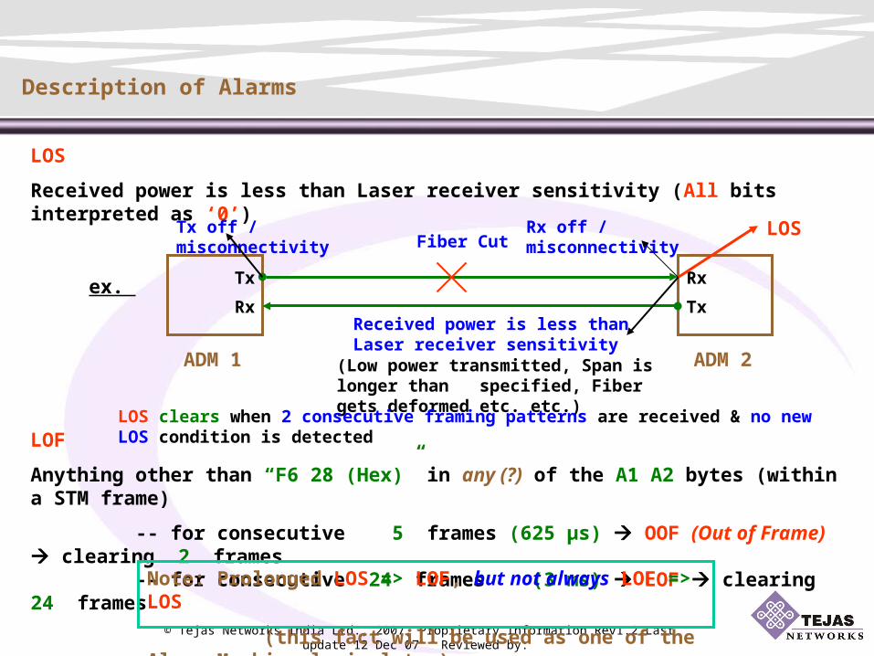
Description of Alarms
LOS
Received power is less than Laser receiver sensitivity (All bits interpreted as ‘0’)
ADM 1 ADM 2
ex. TxRx
RxTx
LOSTx off / misconnectivity Rx off / misconnectivityFiber Cut
Received power is less than Laser receiver sensitivity
(Low power transmitted, Span is longer than specified, Fiber gets deformed etc. etc.)
LOF
Anything other than “F6 28 (Hex)” in any (?) of the A1 A2 bytes (within a STM frame)
-- for consecutive 5 frames (625 µs) OOF (Out of Frame) clearing 2 frames -- for consecutive 24 frames (3 ms) LOF clearing 24 frames
Note: Prolonged LOS => LOF, but not always LOF => LOS
(this fact will be used as one of the Alarm Masking logic later)
LOS clears when 2 consecutive framing patterns are received & no new LOS condition is detected

© Tejas Networks India Ltd., 2007, Proprietary Information Rev1.2 Last update 12 Dec 07 Reviewed by:
Description of Alarms (…contd.)
TIM (J0)
Received J0 trace (1/16 byte(s)) != Expected J0 trace (1/16 byte(s))
Note: For both SF & SD, alarm clearing threshold is 1 decade lower than generation threshold, e.g., Gen. Thr. is 1 in 1000 or higher => Clg. Thr. is 1 in 10000 or lower
SF (B1/B2/B3/V5)
Equivalent BER exceeds alarm generation threshold ( 1 in 10 / 1 in 10 / 1 in 10 )
3 4 5
5 9SD (B1/B2/B3/V5)
Equivalent BER exceeds alarm generation threshold ( 1 in 10 to 1 in 10 )
P1
P2
A B C
Rx trace = C to B
Rx trace = A to B
Tx trace = A to B
Exp trace = A to B
Tx trace = C to BExp trace = C to B

© Tejas Networks India Ltd., 2007, Proprietary Information Rev1.2 Last update 12 Dec 07 Reviewed by:
Description of Alarms (…contd.)
Generation of AIS & RDI
Upon Receiving traffic affecting RS alarm, a Reg.
generates AIS towards downstream side
(all ‘1’ in whole STM frame)
Upon Receiving traffic affecting RS alarm, a ADM
generates MS-AIS towards downstream side
(all ‘1’ in whole STM frame minus RSOH)
& generates MS-RDI towards upstream side
(in K2 byte b6 -- b8 set as ‘110’)
Upon Receiving traffic affecting HP alarm, a ADM
generates AU-AIS towards downstream side
(all ‘1’ in whole AU)
& generates HP-RDI towards upstream side
(in G1 byte b5 set as ‘1’)
© Tejas Networks India Ltd., 2007, Proprietary Information Rev1.2 Last update 12 Dec 07 Reviewed by:
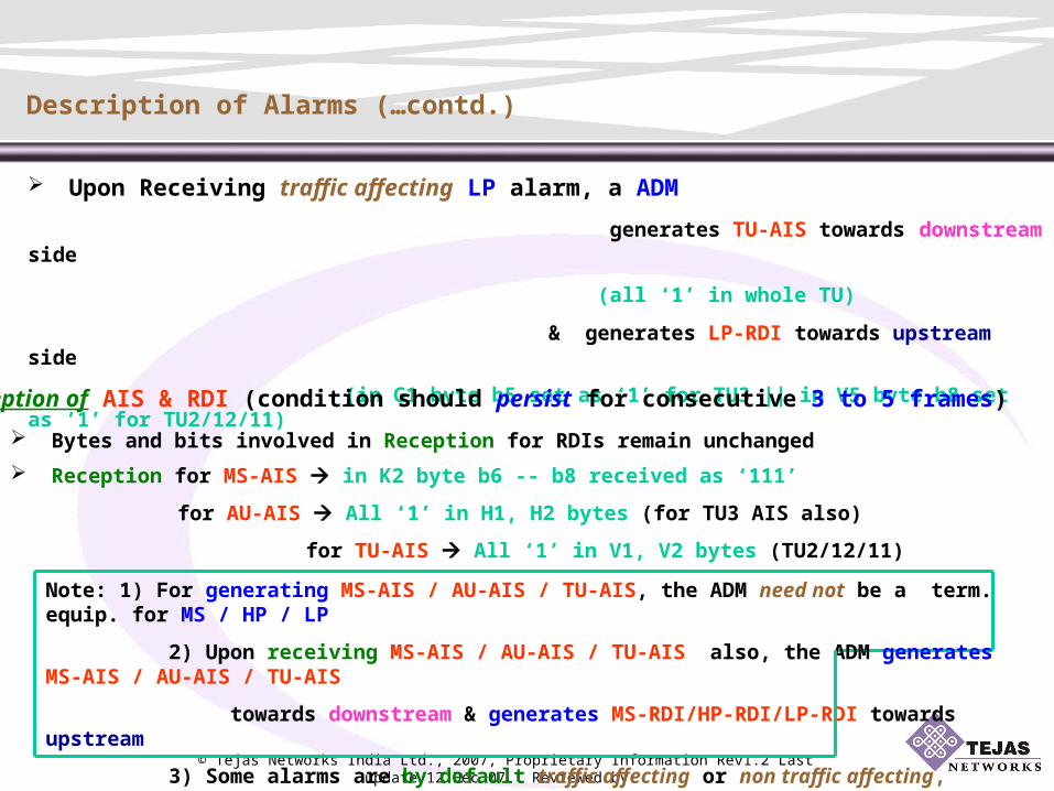
Description of Alarms (…contd.)
Note: 1) For generating MS-AIS / AU-AIS / TU-AIS, the ADM need not be a term. equip. for MS / HP / LP
2) Upon receiving MS-AIS / AU-AIS / TU-AIS also, the ADM generates MS-AIS / AU-AIS / TU-AIS
towards downstream & generates MS-RDI/HP-RDI/LP-RDI towards upstream
3) Some alarms are by default traffic affecting or non traffic affecting, whereas
some alarms can be made traffic affecting by user action
Bytes and bits involved in Reception for RDIs remain unchanged
Upon Receiving traffic affecting LP alarm, a ADM
generates TU-AIS towards downstream side
(all ‘1’ in whole TU)
& generates LP-RDI towards upstream side
(in G1 byte b5 set as ‘1’ for TU3 || in V5 byte b8 set as ‘1’ for TU2/12/11)
Reception of AIS & RDI (condition should persist for consecutive 3 to 5 frames)
Reception for MS-AIS in K2 byte b6 -- b8 received as ‘111’
for AU-AIS All ‘1’ in H1, H2 bytes (for TU3 AIS also)
for TU-AIS All ‘1’ in V1, V2 bytes (TU2/12/11)

© Tejas Networks India Ltd., 2007, Proprietary Information Rev1.2 Last update 12 Dec 07 Reviewed by:
Description of Alarms (…contd.)
Example of generation of AIS, RDI
ADM
Any traffic affecting RS Alarm or MS-AIS (Rx)MS-AIS (Gen)
MS-RDI
Any traffic affecting HP Alarm or AU-AIS (Rx)AU-AIS (Gen)
HP-RDI
Any traffic affecting LP Alarm or TU-AIS (Rx)TU-AIS (Gen)
LP-RDI
Example of reception of TU-AIS, LP-RDI
ADM 1 ADM 2 ADM 3
E1 E1
VC12 VC12 VC12
TU-AIS (Rx)
LP-RDI (Rx)
Any traffic affecting RS/HP/LP Alarm

© Tejas Networks India Ltd., 2007, Proprietary Information Rev1.2 Last update 12 Dec 07 Reviewed by:
Description of Alarms (…contd.)
AU/TU-LOP (AU-LOP is not reported in Tejas nodes, as always valid AU pointer values are sent)
8/9/10 consecutive invalid AU/TU pointers received or
8/9/10 consecutive NDF (New Data Flag) received (other than in a concatenation indicator)
E4 E4
VC4 VC4
AU-LOP
AU-LOP
(cleared when 3 equal valid pointers received)
E1 E1
VC12 VC12
TU-LOP
TU-LOPADM 1 ADM 2 ADM 3
Ex.
ADM 1 ADM 2 ADM 3
Ex.

© Tejas Networks India Ltd., 2007, Proprietary Information Rev1.2 Last update 12 Dec 07 Reviewed by:
Description of Alarms (…contd.)
HP/LP-UNEQ
All ‘0’ in C2 byte for at least 5 frames (for AU4/AU3/TU3)
‘000’ in V5 byte, bits 5,6,7 for at least 5 multi-frames (for TU2/12/11)
ADM 1 ADM 2
ex. AU Sig. Label UNEQuipped
UNEQuipped AU Sig. Label
AU has
no XC
AU has
no XC
HP-UNEQ
HP-UNEQ
ADM 1 ADM 2
ex.
E1
VC12AU has
no XC
UNEQuipped AU Sig. Label
AU Sig. Label TUG-structured
HP-UNEQ

© Tejas Networks India Ltd., 2007, Proprietary Information Rev1.2 Last update 12 Dec 07 Reviewed by:
Description of Alarms (…contd.)
LOM
Multiframe information not recovered from H4 byte (bits 7,8) for 1 to 5 ms
(i.e., 2 to 10 multi-frames)
TIM (J1/J2) (Default action is to “Ignore TIM”)
Concept is like TIM (J0), but
a) Remember Section Hierarchy – Tx trace (J1/J2) can not be edited within a HP/LP
Note: LOM is an alarm concerning LP, but inferred from HOPOH byte – so,
it will be reported on a HO object
DA B CVC12 VC12
E1 E1
VC12 VC4
Tx trace can be edited for J0, J1, J2 all
Tx trace can be edited for J0 only
Tx trace can be edited for J0, J1 only
b) All trace lengths are now 16/64 bytes

© Tejas Networks India Ltd., 2007, Proprietary Information Rev1.2 Last update 12 Dec 07 Reviewed by:
Description of Alarms (…contd.)
HP/LP-PLM (SLM) (Default action is to “Report PLM, but no Downstream AIS”)
Mismatch in ‘own’ and ‘received’ signal label
in C2 byte for at least 5 frames (for AU4/AU3/TU3)
in V5 byte, bits 5,6,7 for at least 5 multi-frames (for TU2/12/11)
ADM 1 ADM 2
ex.
AU Sig. Label TUG-structured
UNEQuipped AU Sig. Label
TUG-ST
UNEQ
TUG-ST
UNEQ
HP-PLM (SLM)
HP-PLM (SLM)
E1
VC12AU has
no XC
Asynch. C4
TUGST
E1
VC12 VC12 VC4
E1
ADM 1 ADM 3
ex.
ADM 2
Asynch. C4
TUGST
Asynch. C4
TUGST
Asynch. C4
TUGST
HP-PLM (SLM) on all ports

© Tejas Networks India Ltd., 2007, Proprietary Information Rev1.2 Last update 12 Dec 07 Reviewed by:
Masking of Alarms
Why?
Do not want to crowd the alarm reporting page ( and thereby confuse the user) with those alarms, not required for unearthing the root cause
When? (The logics)
Logic 1 (when the alarms are related)
if ( FC1 ==> FC2 but FC2 =/=> FC1 )
then ( Mask FC2 in presence of FC1 )
Note: When FC1 clears, FC2 may or may not clear – in the later case FC2 will be reported now
ex. 1a) LOS ==> LOF but LOF =/=> LOS 1b) LOS ==> HP-UNEQ but HP-UNEQ =/=> LOS
2) AU-AIS reported because of MS/AU-AIS generated
==> HP-RDI and
TU-AIS & LP-RDI(s) reported (if TU object(s) are there) but not vice-versa
4) AU/TU-AIS reported ==> AU/TU-LOP but not vice-versa
3) HP-UNEQ because of no XC at other end
==> TU-LOP(s) (if TU object(s) are there) but not vice-versa

© Tejas Networks India Ltd., 2007, Proprietary Information Rev1.2 Last update 12 Dec 07 Reviewed by:
Masking of Alarms (…contd.)
Note: When FC1 clears, FC2 will be reported
Logic 2 (when the alarms are not related)
if ( FC1 has higher priority than FC2 )
then ( Mask FC2 in presence of FC1 )
ex. 1) AU/TU-LOP has higher priority than HP/LP-UNEQ
(if one is not getting the starting location of VC, how to look at what is happening within VC)
2) HP/LP-TIM, if action is chosen as “Report TIM, Downstream AIS” (i.e. traffic affecting)
has higher priority than HP/LP-RDI
(first correct received problem, then only look for problem in other direction)
3) HP/LP-TIM has higher priority than HP/LP-PLM
(first correct mis-connection, then see signal label problem within correct correction)
4) HP/LP-UNEQ has higher priority than HP/LP-TIM (even if traffic affecting)
(what to gain by correcting mis-connection, if even after that traffic can not be carried)
© Tejas Networks India Ltd., 2007, Proprietary Information Rev1.2 Last update 12 Dec 07 Reviewed by:
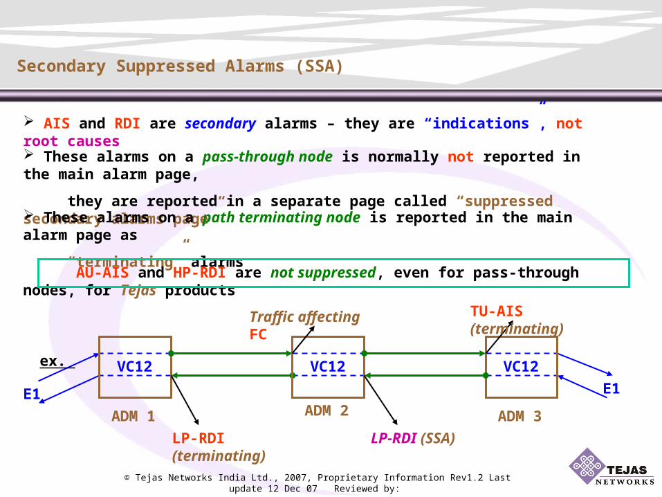
Secondary Suppressed Alarms (SSA)
AIS and RDI are secondary alarms – they are “indications”, not root causes
E1
VC12 VC12VC12
E1
ADM 1 ADM 3
ex.
ADM 2
These alarms on a pass-through node is normally not reported in the main alarm page,
they are reported in a separate page called “suppressed secondary alarms page”
These alarms on a path terminating node is reported in the main alarm page as
“terminating” alarms
AU-AIS and HP-RDI are not suppressed, even for pass-through nodes, for Tejas products
Traffic affecting FC TU-AIS (terminating)
LP-RDI (terminating) LP-RDI (SSA)

© Tejas Networks India Ltd., 2007, Proprietary Information Rev1.2 Last update 12 Dec 07 Reviewed by:
Alarm Propagation Examples
For every example,
Assumption(s) is/are stated
Root Cause(s) is/are stated
Diagrammatic representation is made (OFCs are shown in cyan)
Alarm(s) generated / condition(s) generated for reporting alarms is/are
shown in black Alarm(s) existing at a port is/are shown in red
Alarm(s) masked at a port is/are covered with
Alarm(s) reported at secondary supprressed alarm page is/are shown
in pink, italicised
Note(s), whenever required is/are mentioned in green
© Tejas Networks India Ltd., 2007, Proprietary Information Rev1.2 Last update 12 Dec 07 Reviewed by:
Alarm Propagation Examples (…contd.)
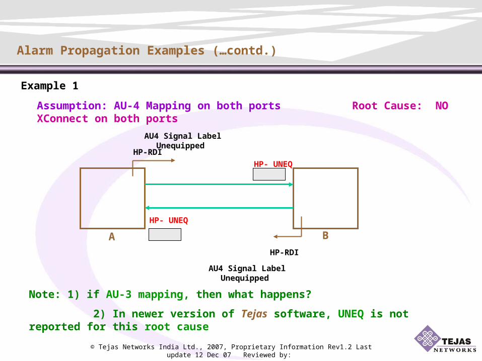
Example 1
A B
Assumption: AU-4 Mapping on both ports Root Cause: NO XConnect on both ports
AU4 Signal Label Unequipped
HP-RDI
HP- UNEQ
HP-RDI
AU4 Signal Label Unequipped
HP- UNEQ
HP-RDI
HP-RDI
Note: 1) if AU-3 mapping, then what happens?
2) In newer version of Tejas software, UNEQ is not reported for this root cause

© Tejas Networks India Ltd., 2007, Proprietary Information Rev1.2 Last update 12 Dec 07 Reviewed by:
Alarm Propagation Examples (…contd.)
HP-RDI
HP- UNEQ
AU4 Signal Label Unequipped
Signal Label TUG-structure
HP-SLM
HP-RDI
TU-LOP
Example 2
Assumption: AU-4 Mapping on both ports, Root Cause: NO XConnect on the port of B
A B
E1
VC12
Invalid TU Pointer value
LP-RDI
Note: LP-RDI is not reported on B (See Rule 3a)
HP-SLM default action is “report SLM, no downstream AIS”

© Tejas Networks India Ltd., 2007, Proprietary Information Rev1.2 Last update 12 Dec 07 Reviewed by:
LOS
MS-AIS
AU-AIS
TU-AIS
MS-RDI
HP-RDI
LP-RDI
Alarm Propagation Examples (…contd.)
VC-12 VC-12
E1 E1
A CB (Reg.)
Example 3
Assumption: AU-4 Mapping on both ports of A & C
Root Cause: Fiber cut in the link from A to B
AIS
MS-RDI
HP-RDI
LP-RDINote: The Reg. can not generate any RDI
Actually at C, AU-AIS & TU-AIS conditions are also received

© Tejas Networks India Ltd., 2007, Proprietary Information Rev1.2 Last update 12 Dec 07 Reviewed by:
LOS
MS-RDI
HP-RDI
LP RDI
Alarm Propagation Examples (…contd.)
MS-AIS
LP RDI MS-RDI
HP-RDI
E1 E1
VC-12 VC-12
A CB
Example 4
Assumption: AU-4 Mapping on all ports Root Cause: Fiber cut in the link from A to B
VC-12
ADM B VC-12 PT
TU AIS
Note: Only TU-AIS is reported on Node C (See Rule 4c)
LP RDI
LP-RDI on B is SSA

© Tejas Networks India Ltd., 2007, Proprietary Information Rev1.2 Last update 12 Dec 07 Reviewed by:
LOS
MS-RDI
HP-RDI
LP RDI
Alarm Propagation Examples (…contd.)
MS-AIS
LP RDI MS-RDI
HP-RDI
E1 E1
VC-12 VC-12
A CB
Example 5
Assumption: AU-4 Mapping on all ports Root Cause: Fiber cut in the link from A to B
VC-4
ADM B VC-4 PT
Note: Only AU-AIS is reported on Node C (See Rule 4c)
LP-RDI on B is not reported (See Rule 3b)
AU AIS
TU AIS

© Tejas Networks India Ltd., 2007, Proprietary Information Rev1.2 Last update 12 Dec 07 Reviewed by:
Invalid TU Pointers (1-1-2)
TU-LOP (1-1-2)
A DCB
E1
(2)
VC-12 (1-1-2)
Example 6
Assumption: AU-4 Mapping on all ports Root cause: NO XConnect on B, C & D for (1-1-2)
E1 (1)E1 (1)
VC-12 (1-1-1)
LP RDI (1-1-2)
Note: Why E1(1) is shown?
LP-RDI is not reported on B (See Rule 3a)
Alarm Propagation Examples (…contd.)

© Tejas Networks India Ltd., 2007, Proprietary Information Rev1.2 Last update 12 Dec 07 Reviewed by:
Invalid TU Pointers (1-1-2)
TU-LOP (1-1-2)
LP RDI (1-1-2)
Note: LP-RDI at node B is secondary suppressed
TU-AIS at node A is reported as terminating alarm
Alarm Propagation Examples (…contd.)
VC-12 (1-1-2)
A DCB
Example 7
Assumption: AU-4 Mapping on all ports Root cause: NO XConnect on C & D for (1-1-2)
E1 (1)E1 (1)
VC-12 (1-1-1)
E1
(2)
VC-12 (1-1-2)
TU-AIS (1-1-2)
TU AIS (1-1-2)
LP RDI (1-1-2)
LP-RDI (1-1-2)

© Tejas Networks India Ltd., 2007, Proprietary Information Rev1.2 Last update 12 Dec 07 Reviewed by:
Invalid TU Pointers (1-1-2)
TU-LOP (1-1-2)
LP RDI (1-1-2)
Note: K-L-M value need not remain same throughout a particular LP, alarms will
be reported accordingly on different objects
Alarm Propagation Examples (…contd.)
TU-AIS (1-1-2)
TU AIS (1-1-2)
LP RDI (1-1-2)
LP-RDI (1-1-2)
VC-12 (1-1-2)
A DCB
Example 8
Assumption: AU-4 Mapping on all ports Root cause: NO XConnect on C for (1-1-2)
E1 (1)E1 (1)
VC-12 (1-1-1)
E1
(2)
VC-12 (1-1-2) E1
(2)
VC12(1-1-2)
Invalid TU Pointers (1-1-2)
TU-LOP (1-1-2)
LP RDI (1-1-2)

© Tejas Networks India Ltd., 2007, Proprietary Information Rev1.2 Last update 12 Dec 07 Reviewed by:
Invalid TU Pointers
(1-1-1)
TU-LOP
(1-1-1)
LP-RDI
(1-1-1)
Note: LP-RDI from A is not reported on B (See Rule 3b).
Why assumption on SLM?
Alarm Propagation Examples (…contd.)
A CB
VC-12(1-1-1)
VC-4 VC-12(1-1-2)VC-12(1-1-2)E1 (1)
E1 (2)
E1(2)
Example 9
Assumption: AU-4 Mapping on all ports, Root cause: NO XConnect on C for (1-1-1)
VC4 PT at node B,
For each port, HP-SLM default action is “ignore SLM”
© Tejas Networks India Ltd., 2007, Proprietary Information Rev1.2 Last update 12 Dec 07 Reviewed by:
LOS
MS-RDI
HP-RDI
LP RDI
TU AIS
LP RDI
MS-AIS
LP RDI MS-RDI
HP-RDI
Alarm Propagation Examples (…contd.)
VC-12VC-12
VC-12
E1 E1
A CB
D
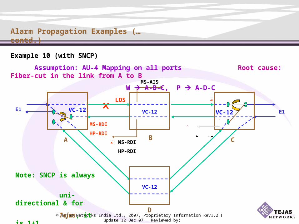
Example 10 (with SNCP)
Assumption: AU-4 Mapping on all ports Root cause: Fiber-cut in the link from A to B
W A-B-C, P A-D-C
VC-12
Note: SNCP is always
uni-directional & for
Tejas, it is 1+1

© Tejas Networks India Ltd., 2007, Proprietary Information Rev1.2 Last update 12 Dec 07 Reviewed by:
Thank You…