2-post rack mount kit installation...
TRANSCRIPT
���
2-Post Rack Mount Kit Installation Instructions
Review the documentation that comes with your rack for safety and cabling information. Before installing
your server in a rack, review the following guidelines:
v Three or more people are required to install the device in a rack.
v Use shear plates for any unused U spaces within a rack.
v Connect the BladeCenter® T Type 8730 unit to a 220-volt power distribution unit (PDU) or to a
properly grounded 220-volt power outlet. Connect the BladeCenter T Type 8720 unit to the overhead
direct current (dc) power source.
v The BladeCenter T unit is designed to be rack-compatible with NEBS-compliant 2-post racks.
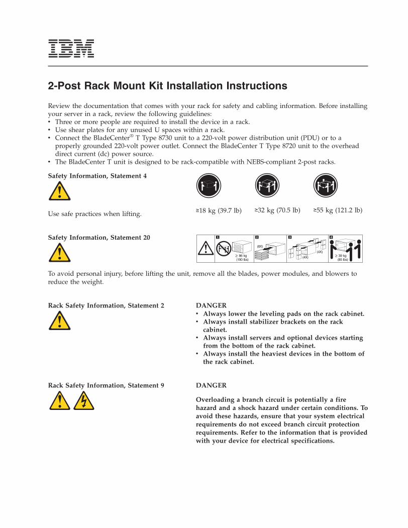
Safety Information, Statement 4
Use safe practices when lifting.
≥18 kg (39.7 lb)
≥32 kg (70.5 lb)
≥55 kg (121.2 lb)
Safety Information, Statement 20
(8X)
(4X)
(4X)86 kg
(190 lbs)39 kg
(85 lbs)
To avoid personal injury, before lifting the unit, remove all the blades, power modules, and blowers to
reduce the weight.
Rack Safety Information, Statement 2
DANGER
v Always lower the leveling pads on the rack cabinet.
v Always install stabilizer brackets on the rack
cabinet.
v Always install servers and optional devices starting
from the bottom of the rack cabinet.
v Always install the heaviest devices in the bottom of
the rack cabinet.
Rack Safety Information, Statement 9
DANGER
Overloading a branch circuit is potentially a fire
hazard and a shock hazard under certain conditions. To
avoid these hazards, ensure that your system electrical
requirements do not exceed branch circuit protection
requirements. Refer to the information that is provided
with your device for electrical specifications.
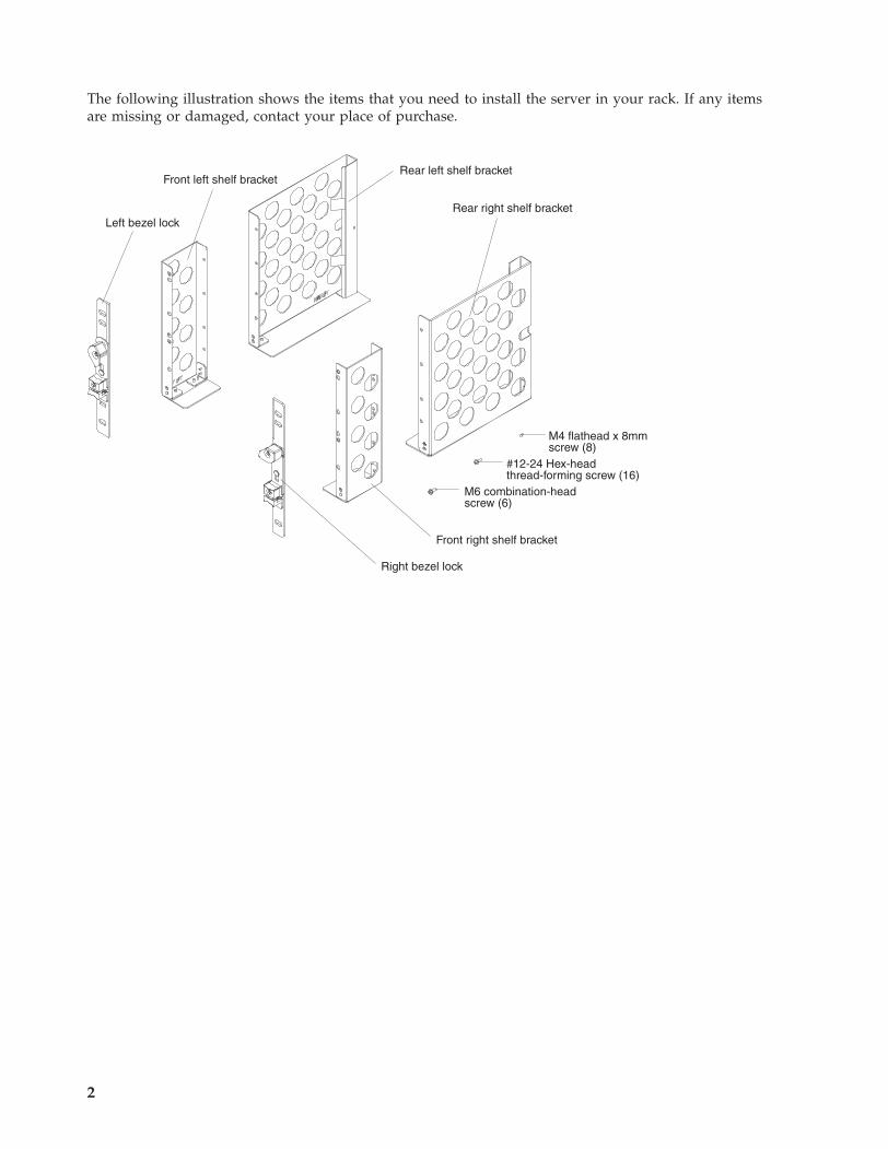
The following illustration shows the items that you need to install the server in your rack. If any items
are missing or damaged, contact your place of purchase.
Rear left shelf bracket
Rear right shelf bracket
Front left shelf bracket
Front right shelf bracket
M4 flathead x 8mmscrew (8)
M6 combination-headscrew (6)
#12-24 Hex-headthread-forming screw (16)
Right bezel lock
Left bezel lock
2
1
4 #12 x 24 hex-headthread-formingscrews per bracket
CMM1
CMM2
ESD
2
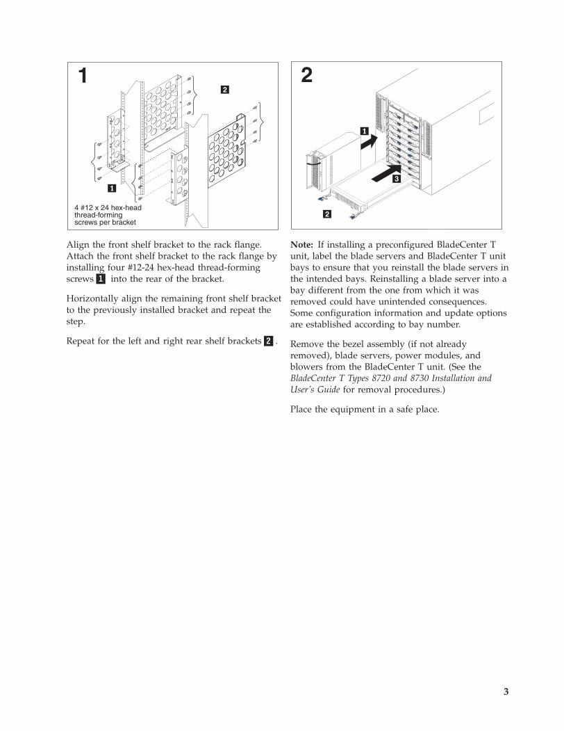
Align the front shelf bracket to the rack flange.
Attach the front shelf bracket to the rack flange by
installing four #12-24 hex-head thread-forming
screws�1� into the rear of the bracket.
Horizontally align the remaining front shelf bracket
to the previously installed bracket and repeat the
step.
Repeat for the left and right rear shelf brackets�2�.
Note: If installing a preconfigured BladeCenter T
unit, label the blade servers and BladeCenter T unit
bays to ensure that you reinstall the blade servers in
the intended bays. Reinstalling a blade server into a
bay different from the one from which it was
removed could have unintended consequences.
Some configuration information and update options
are established according to bay number.
Remove the bezel assembly (if not already
removed), blade servers, power modules, and
blowers from the BladeCenter T unit. (See the
BladeCenter T Types 8720 and 8730 Installation and
User’s Guide for removal procedures.)
Place the equipment in a safe place.
3
3
ESD ESD
30
0W
4
ESD ESD
30
0W
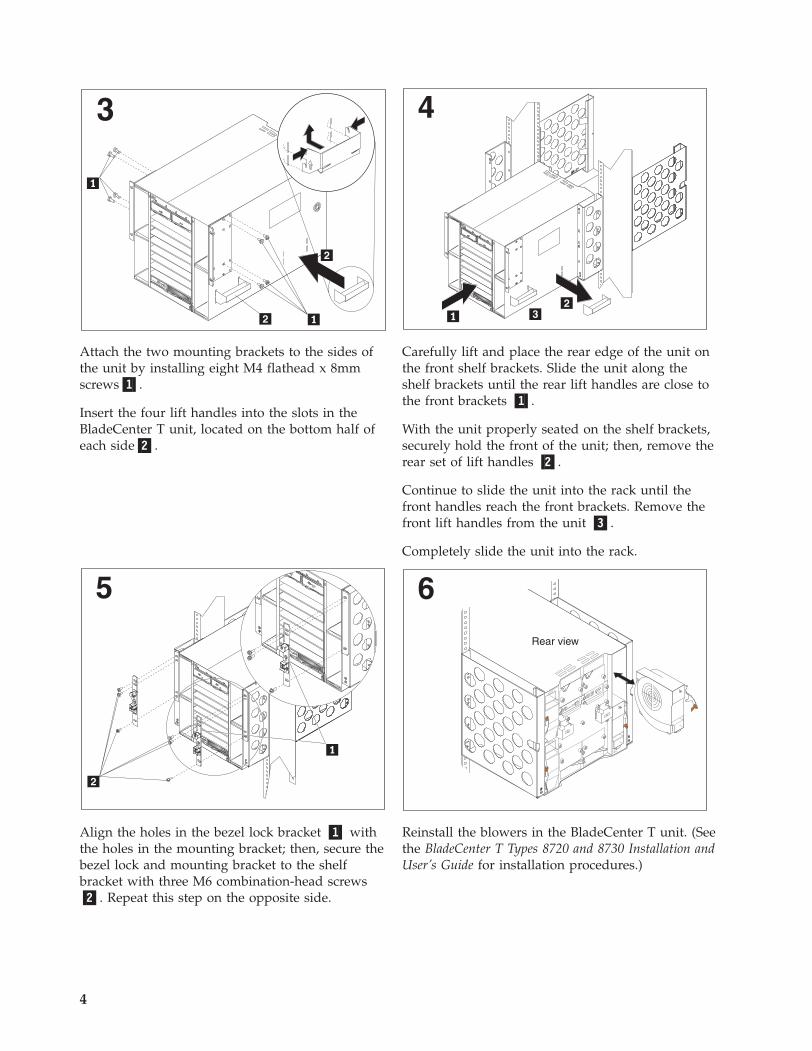
Attach the two mounting brackets to the sides of
the unit by installing eight M4 flathead x 8mm
screws�1�.
Insert the four lift handles into the slots in the
BladeCenter T unit, located on the bottom half of
each side�2�.
Carefully lift and place the rear edge of the unit on
the front shelf brackets. Slide the unit along the
shelf brackets until the rear lift handles are close to
the front brackets �1�.
With the unit properly seated on the shelf brackets,
securely hold the front of the unit; then, remove the
rear set of lift handles �2�.
Continue to slide the unit into the rack until the
front handles reach the front brackets. Remove the
front lift handles from the unit �3�.
Completely slide the unit into the rack.
5
ESD ESD
30
0W
ESD ESD
6
24
13
Rear view
Align the holes in the bezel lock bracket �1� with
the holes in the mounting bracket; then, secure the
bezel lock and mounting bracket to the shelf
bracket with three M6 combination-head screws
�2�. Repeat this step on the opposite side.
Reinstall the blowers in the BladeCenter T unit. (See
the BladeCenter T Types 8720 and 8730 Installation and
User’s Guide for installation procedures.)
4
TOP D TOP D
BTM E BTM E
1 3
CRTMJR
MNR
2Alarms
1
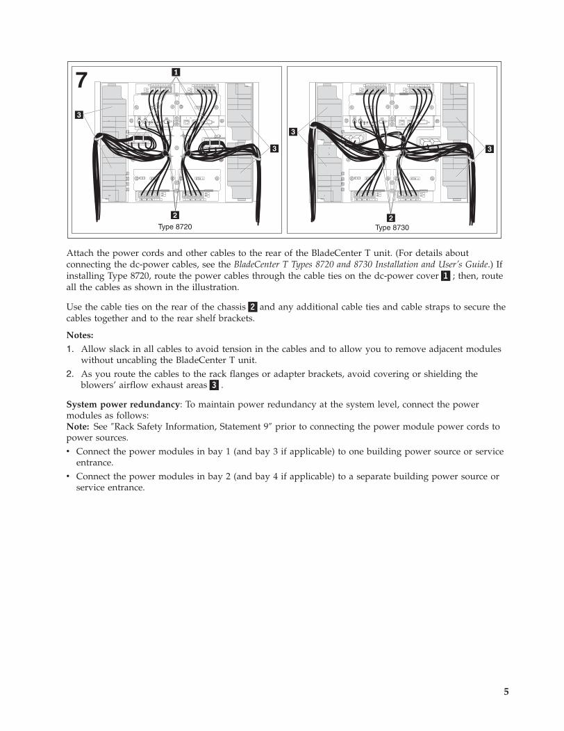
Type 8720
7TOP D TOP D
BTM E BTM E
2 41 3
CRTMJR
MNR
2Alarms
1
Type 8730
Attach the power cords and other cables to the rear of the BladeCenter T unit. (For details about
connecting the dc-power cables, see the BladeCenter T Types 8720 and 8730 Installation and User’s Guide.) If
installing Type 8720, route the power cables through the cable ties on the dc-power cover�1�; then, route
all the cables as shown in the illustration.
Use the cable ties on the rear of the chassis�2�and any additional cable ties and cable straps to secure the
cables together and to the rear shelf brackets.
Notes:
1. Allow slack in all cables to avoid tension in the cables and to allow you to remove adjacent modules
without uncabling the BladeCenter T unit.
2. As you route the cables to the rack flanges or adapter brackets, avoid covering or shielding the
blowers’ airflow exhaust areas�3�.
System power redundancy: To maintain power redundancy at the system level, connect the power
modules as follows:
Note: See ″Rack Safety Information, Statement 9″ prior to connecting the power module power cords to
power sources.
v Connect the power modules in bay 1 (and bay 3 if applicable) to one building power source or service
entrance.
v Connect the power modules in bay 2 (and bay 4 if applicable) to a separate building power source or
service entrance.
5
8CMM
1
CMM2
ESD
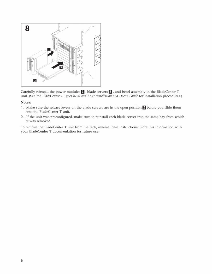
Carefully reinstall the power modules�1�, blade servers�3�, and bezel assembly in the BladeCenter T
unit. (See the BladeCenter T Types 8720 and 8730 Installation and User’s Guide for installation procedures.)
Notes:
1. Make sure the release levers on the blade servers are in the open position�2�before you slide them
into the BladeCenter T unit.
2. If the unit was preconfigured, make sure to reinstall each blade server into the same bay from which
it was removed.
To remove the BladeCenter T unit from the rack, reverse these instructions. Store this information with
your BladeCenter T documentation for future use.
6

7
Third Edition (July 2006)
IBM and BladeCenter are trademarks of the IBM Corporation in the United States, other countries, or both.
Printed in the U.S.A.
© Copyright International Business Machines Corporation 2006. All rights reserved.
US Government Users Restricted Rights – Use, duplication or disclosure restricted by GSA ADP Schedule Contract
with IBM Corp.
(1P) P/N: 31R1708