2 general introduction - fusion: fusion - a clean · pdf file · 2014-08-13and...
TRANSCRIPT

Annual Report of the EURATOM/CCFE Fusion Programme 2013
2.1 7. Technology
7 Technology
7.1 POWER PLANT STUDIES The CCFE contribution to the programme of the EFDA Power Plant Physics and Technology Department (PPPT) showed a slight decrease in terms of manpower compared to 2012 (12.4PPY compared to 14.1PPY) with a 69% bid success rate, but still represents ~25% of the total funding to the Technology Programme and represents the largest single commitment in the Technology programme.
7.1.1 SYSTEM STUDIES Previous work in 2012 within the PPPT DEMO baseline group had identified reasonable working points for the pulsed DEMO and an alternative steady state tokamak. These were used as the basis for a series of sensitivity studies, using CCFE’s PROCESS systems code, to assess their sensitivity to key variables. As part of the work, improvements were also made to PROCESS when improved models became available, in particular the addition of a new blanket model and a detailed review of the stress modelling in the toroidal field (TF) coils. An improved plasma radiation model, allowing a wider range of impurities and a profile parameterisation including a pedestal, was also investigated for future inclusion. Factors investigated within the sensitivities studies included the impact on plant design of improving materials within the toroidal field coils; identifying operating windows above the L-H power threshold but below divertor power-handling limits; optimisation of the aspect ratio for a pulsed plant with self-consistent TF coil modelling; impact of core radiation fraction on pulse length; effects of increasing pulse length by increasing current-drive power on plant electrical output; and current-drive system efficiency impacts. The principal conclusion is that divertor protection still remains a critical issue for both designs, and that how this is accomplished has a strong effect on the design choices. In addition further work is required on the factors which set the performance limits in steady state, particularly the interaction of the assumed H-factor and beta limit. 7.1.2 SAFETY AND DESIGN CRITERIA
CCFE played a major role in the new Safety Work Package within the PPPT work programme, producing two documents – a DEMO Safety Requirements Discussion document and Preliminary DEMO Safety Design Guidelines. The Requirements Document followed an extensive review of US DoE standards, IAEA Safety Standards, ICRP guidance, and available ITER, DEMO and Japanese DDA Safety Approach documentation. It defines the fundamental safety requirements and safety functions for the design and operations envelope of DEMO. One of the key points is
7. T
ech
no
log
y

Annual Report of the EURATOM/CCFE Fusion Programme 2013
2.2 7 Technology
the need to minimise the amount of material requiring disposal either by recycling or by reducing resource use through design. This aspect of the safety requirements is synergistic with CCFE’s aim to nurture and exploit the advanced manufacturing techniques and new materials being developed by UK Universities and industry under the Technology Growth Programme. The preliminary DEMO safety design guidelines document describes the design process and safety interfaces and provides guidance on a range of safety and engineering assessment options for designers. There is a strong synergy with the PPPT task on the development of design tools, methodologies and structural design criteria (SDC) for fusion that CCFE leads. Having gained an understanding of the required content for a DEMO specific SDC, work focused on filling priority gaps through the investigation of alternative non-ductile failure rules and the development of a creep fatigue design tool. In addition, CCFE investigated the possibility of including fracture mechanics based fatigue calculations, concluding that this would provide a much needed increase in design space. Finally CCFE have created a development plan detailing the high level design criteria requirements and providing a strategy to successfully deliver the DEMO SDC to the DEMO in vessel component designers during the conceptual design phase. 7.1.3 RAMI The CCFE technology programme has held a prominent role in 2013 in developing design tools and methodologies in the important area of Reliability, Availability, Maintainability and Inspectability (RAMI) for DEMO. In order to satisfy stakeholder requirements, DEMO must show a predictable level of availability during operations, and the cost and impact of maintenance actions must be minimised through design optimisation. Therefore, RAMI considerations must form an integral part of the DEMO programme and form a component of the overall systems engineering design approach. CCFE led three key areas:
availability of the primary heat transfer and balance of plant systems of the water cooled LiPb blanket concept.
analysis of the time-variant states and modes of DEMO, such as plasma ramp up/down and interpulse dwell, with respect to plant availability.
definition of high level Key Performance Indicators (KPI) for availability that characterise the system performance as a tool to enable demonstration of project success against stakeholder requirements.
The overall availability of DEMO for operations will be determined by the availability of its constituent systems and the probability of successful transitions between states at plant and system level and the duration of the transitions. The different stakeholders will have varying interests in the measures of availability and the proposed KPIs were assessed against those for comparable developmental technologies, such as those in The European Strategic Energy Technology Plan

Annual Report of the EURATOM/CCFE Fusion Programme 2013
2.3 7. Technology
(SET-Plan). These KPIs then inform system design trade-off studies, including a proposal for the future extension of the PROCESS systems code to enable quantitative exploration of differing availability metrics in optimising plant architectures. 7.1.4 HEATING AND CURRENT DRIVE One of the leading candidates for heating and current drive for the DEMO plasma is neutral beam injection (NBI) and the size and density of the DEMO plasma dictates a beam energy of 1.5MeV or more to penetrate the core. Heating of the plasma is required to reach the higher confinement H-mode and to generate the self-sustaining fusion reaction. In addition, because the tokamak is essentially a transformer, there is a finite time for which the plasma can be maintained that depends on the rate of decay of current through the central solenoid; for DEMO this is typically around 1-2hours. Longer pulses require the plasma current to be driven non-inductively and NBI can also serve this purpose. For DEMO the pulse length can be extended up to 4 hours by this method. As DEMO is intended to use near-term technology, it is probable that the NBI system will be similar to that of ITER, based on 1MeV beam energy. To investigate the effects of reducing the beam energy the current drive was compared at 1MeV and 1.5MeV for anticipated plasma profiles with beams injected over a range of radii and elevations, allowing contours of current drive efficiency to be constructed across the plasma profile. It was found that the predicted current drive efficiency, averaged over the whole plasma, was not significantly reduced at the lower beam energy. However, the 1MeV beam would create a less localised driven current distribution within the plasma, with more current driven at the plasma’s outer edge than with the 1.5MeV beam. Because NBI is driving plasma current it can also affect the distribution of current in the plasma, so careful analysis is required to avoid introducing plasma instabilities. CCFE lead the analysis of the optimisation of NBI current drive in the PPPT programme and have developed a methodology based on a Genetic Algorithm to optimise the position and power of the beams to achieve a desired plasma profile. The Genetic Algorithm method was used to investigate the ability to match a target current profile, such as that required to drive a long pulse plasma. For both beam energies, the GA determined optimal combinations of beam tangency, elevation and magnitude of injected power for the resulting driven current to best match the target profile. When the beam energy is reduced to 1MeV in the same scenario the total power required would be greater with more current being driven at the edge resulting in a less optimal fit to the target profile. Although it is not proposed to drive all the current in a near term DEMO device using beams, this is a useful result in helping determine requirements regarding beamline tangency and elevation for optimal deployment of NBCD.
Annual Report of the EURATOM/CCFE Fusion Programme 2013
2.4 7 Technology
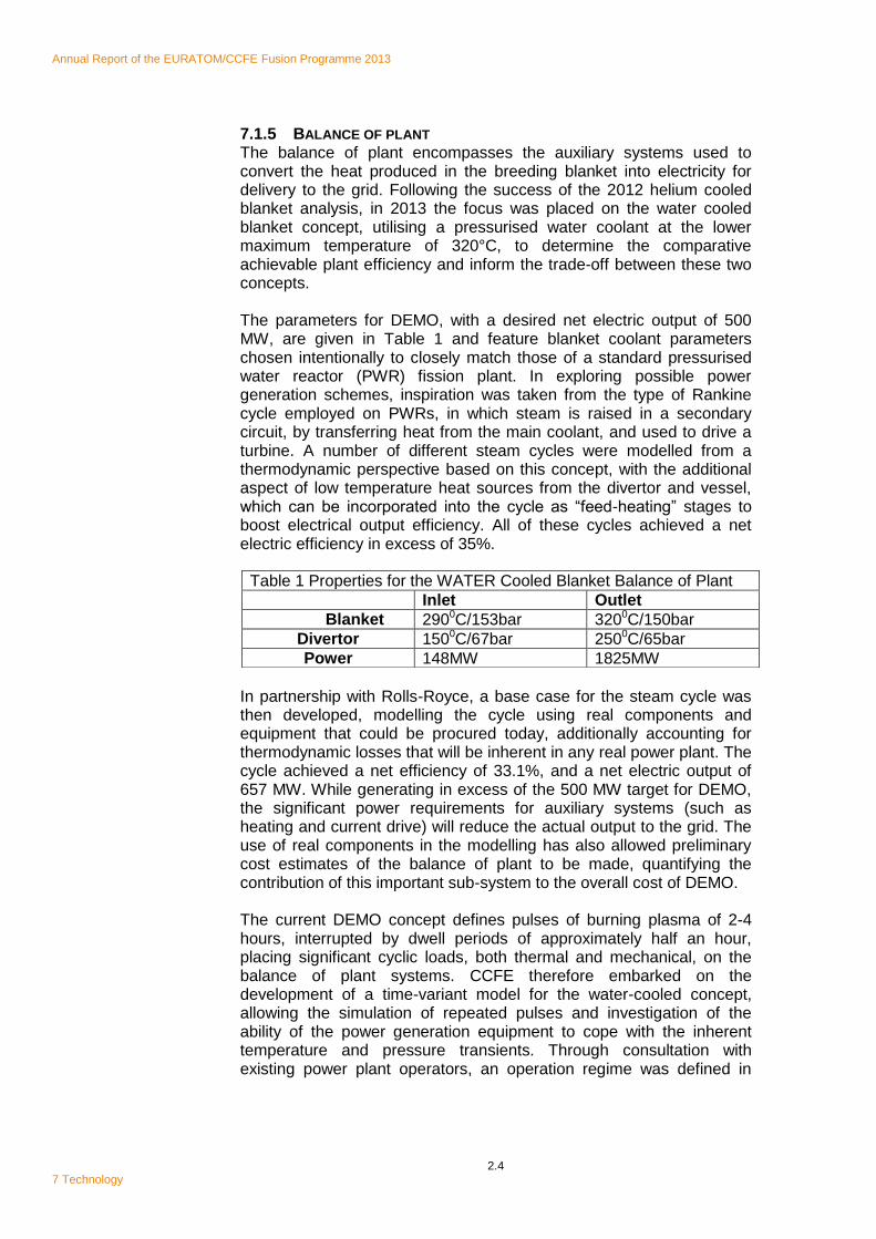
7.1.5 BALANCE OF PLANT The balance of plant encompasses the auxiliary systems used to convert the heat produced in the breeding blanket into electricity for delivery to the grid. Following the success of the 2012 helium cooled blanket analysis, in 2013 the focus was placed on the water cooled blanket concept, utilising a pressurised water coolant at the lower maximum temperature of 320°C, to determine the comparative achievable plant efficiency and inform the trade-off between these two concepts. The parameters for DEMO, with a desired net electric output of 500 MW, are given in Table 1 and feature blanket coolant parameters chosen intentionally to closely match those of a standard pressurised water reactor (PWR) fission plant. In exploring possible power generation schemes, inspiration was taken from the type of Rankine cycle employed on PWRs, in which steam is raised in a secondary circuit, by transferring heat from the main coolant, and used to drive a turbine. A number of different steam cycles were modelled from a thermodynamic perspective based on this concept, with the additional aspect of low temperature heat sources from the divertor and vessel, which can be incorporated into the cycle as “feed-heating” stages to boost electrical output efficiency. All of these cycles achieved a net electric efficiency in excess of 35%.
In partnership with Rolls-Royce, a base case for the steam cycle was then developed, modelling the cycle using real components and equipment that could be procured today, additionally accounting for thermodynamic losses that will be inherent in any real power plant. The cycle achieved a net efficiency of 33.1%, and a net electric output of 657 MW. While generating in excess of the 500 MW target for DEMO, the significant power requirements for auxiliary systems (such as heating and current drive) will reduce the actual output to the grid. The use of real components in the modelling has also allowed preliminary cost estimates of the balance of plant to be made, quantifying the contribution of this important sub-system to the overall cost of DEMO. The current DEMO concept defines pulses of burning plasma of 2-4 hours, interrupted by dwell periods of approximately half an hour, placing significant cyclic loads, both thermal and mechanical, on the balance of plant systems. CCFE therefore embarked on the development of a time-variant model for the water-cooled concept, allowing the simulation of repeated pulses and investigation of the ability of the power generation equipment to cope with the inherent temperature and pressure transients. Through consultation with existing power plant operators, an operation regime was defined in
Table 1 Properties for the WATER Cooled Blanket Balance of Plant
Inlet Outlet
Blanket 2900C/153bar 3200C/150bar
Divertor 1500C/67bar 2500C/65bar
Power 148MW 1825MW

Annual Report of the EURATOM/CCFE Fusion Programme 2013
2.5 7. Technology
which the temperatures of the blanket and all associated components within the primary circuit can be kept within allowable limits, while pressure transients, caused by variations in coolant temperature, can be successfully managed. Dynamic modelling has also allowed simulation of the pulsed behaviour of one of the key components of concern for the balance of plant – the steam turbine. Cool-down of the turbine internals during the dwell and the resulting induced thermal stresses have been calculated and found to be minimal, instilling some confidence in the ability of the turbine to withstand regular pulsing. This has been confirmed for PWR-type turbines in a parallel study in collaboration with Rolls-Royce; however, it has also been identified that the cyclic mechanical loading of the turbine blades will be significant, specifically leading to localised plastic deformation and potential cracking at the point of attachment to the turbine disk, which will require a suitable mitigation strategy. These activities have enabled CCFE to understand in greater detail where the most challenging aspects of pulsed operation will lie, drilling down from a systems level understanding of plant interactions, to more localised component-specific risks, which will guide and focus future studies. 7.1.6 WATER COOLED DIVERTOR Building on the success in 2012 of the programme to develop alternative water cooled divertor concepts in PPPT, the focus in 2013 has been to explore a concept proposed by CCFE in 2012 called Thermal Break. This is an evolution of the ITER-like monoblock high heat flux target shown schematically in Figure 7.1.
The most likely cause of failure in this design is the stress in the CuCrZr pipe due to the differential thermal expansion between it and the tungsten monoblock armour. In the Thermal Break concept careful control of the properties of the interlayer between the armour and pipe greatly reduces the structural stress as well as allowing the materials to operate closer to their recommended temperature ranges. The work in 2013 has progressed along two lines: finite-element analysis
based design search and optimisation of the Thermal Break concept, and the initiation of joining and manufacturing processes.
Figure 7.1 Divertor target element comprising tungsten monoblock plasma facing armour, CuCrZr cooling structure and a compliant interlayer

Annual Report of the EURATOM/CCFE Fusion Programme 2013
2.6 7 Technology
Optimising the design of the monoblock with the multiple parameter variants available, such as thermal conductivity of the interlayer, pipe diameter, tungsten wall thickness, would be prohibitively time consuming to perform manually. CCFE therefore developed an automated design search and optimisation process based on the response surfaces method and this has now been adopted as the standard analysis method for this programme. The method calculates a selected property (for example stress) along a number of prescribed paths in the component and compares against its appropriate design code limit to generate a reserve factor (a measure of how close to its design limit the component is taken). By repeating this process for varying component parameters (such as interlayer conductivity, tungsten wall thickness and pipe diameter) an optimised design point can be identified. The analysis shows that stress in the CuCrZr pipe is strongly coupled to the interlayer thermal conductivity, in a highly non-linear manner and that minimum stress is achieved for a conductivity equivalent to ~10% of copper. This has yielded a Thermal Break design, based on 200°C coolant, that passes all the ITER SDC-IC low temperature rules for an incident heat flux of 10MWm-2, with a minimum structural reserve factor of 1.4 and peak tungsten surface temperature limited by recrystallisation to 1300°C. The Thermal Break interlayer reduces the peak heat flux at the top of the coolant pipe by 21% while increasing the minimum heat flux through the bottom of the pipe by 393%. The upper limit of power density, determined by local plastic flow in the CuCrZr pipe, is 18MWm-2. These are extremely encouraging results, as to date the reference concepts for DEMO have not achieved power handling of greater than 10MWm-2. To explore the performance enhancement of Thermal Break, the design studies used a parameterisation of the interlayer material properties rather than real material data. To promote the viability of this concept an appropriate material and joining technology needs to be demonstrated which realises the “target” characteristics determined by design. To address this need a series of manufacturing and joining trials are being performed using a porous copper layer as the Thermal Break interlayer. A bespoke experimental test rig has been designed and constructed at CCFE to measure the interlayer thermal conductance as a function of temperature and pressure under vacuum conditions. Joint mock-ups have been prepared by CCFE Special Techniques Group using a porous copper material (“FeltMetal”) sandwiched between copper sample blocks. 7.1.7 REMOTE MAINTENANCE CCFE continued to lead the DEMO remote maintenance programme in 2013 contributing to all nine tasks, the major being maintenance duration and blanket segment maintenance scheme. A feasible remote handling strategy for DEMO and thereby for fusion power-plants based
Annual Report of the EURATOM/CCFE Fusion Programme 2013
2.7 7. Technology
on the vertical maintenance concept developed during 2012 has been formulated. Building on work in 2012, CCFE continued to develop the estimate for the duration of the remote maintenance of the DEMO blanket segments and divertor cassettes including the impact of the different blanket technology alternatives. Changes to the design of the remote maintenance system have required reassessment of the operations for the maintenance of the divertor cassettes. A divertor port closure plate with an inner and outer port acts as a door within a door. It reduces the maintenance duration for the divertor only replacement by allowing the blanket drain pipes to remain in place. The time savings for the divertor only replacement significantly outweigh the additional time required during the divertor and blanket replacement. Duration data was extrapolated from recorded times and operational experience from remote maintenance activities on the JET tokamak or calculated directly from pre-conceptual component and tool designs. With four remote handling systems operating in parallel, the results indicate that for a highly developed and optimised remote maintenance system, replacing all blankets segments and all divertor cassettes could be achieved in just over 6 months. Replacement of the divertor cassettes alone could be achieved in less than 3 months. Increased parallel working will become more of a necessity with increasing design complexity. Pipe connection operations are critical, accounting for around half of the process time. Successful development of laser cutting and welding would significantly reduce the maintenance duration. CCFE investigated the leading edge technology for cutting and welding operations with the constraints of in-bore operation. TIG welding is a well-developed but slow pipe joining technology. Laser welding needs further work to demonstrate its applicability to the DEMO application through design and mock-up testing. A feasible and substantiated concept has been developed for the blanket segment maintenance, incorporating ‘dog-leg’ interfaces between segments to reduce neutron streaming to the vacuum vessel. This change has impacted on the in-vessel mover and the vertical maintenance crane. The in-vessel mover has been completely redesigned to allow disconnection of the new blanket segment supports from the vessel and is no longer required to move toroidally along the divertor support rails. The vertical maintenance crane has been simplified and adapted to the new segment handling requirements and now includes active cooling for removal of the decay heat. The increased thickness of the blanket segments reduces the gaps between the segments requiring an additional degree of freedom to be added to the vertical maintenance crane transporter which now includes a new articulated arm as shown in Fig 7.2.

Annual Report of the EURATOM/CCFE Fusion Programme 2013
2.8 7 Technology
The remote handling equipment needed for the replacement of the blanket segments has been further developed. Pipes can be cut and welded in parallel, with tools grouped for each segment. The impact of pipe operations on the maintenance duration implies that a blanket design using ceramic pebbles in the tritium breeder would be advantageous as fewer pipe operations are required compared to the liquid lithium lead eutectic breeder. However the liquid metal
alternative allows draining of the blankets before removal, lowering their weight and activation levels.
7.2 TECHNOLOGY GROWTH Technology Growth encompasses all activities undertaken within the Technology Programme that are not directly included within the EFDA PPPT programme. In 2013 this included contributions to materials technology and advanced divertor designs in addition to continuing with development of the 14MeV neutron source concepts. In 2013 the Technology Programme actively sought new partnerships with UK universities to develop the application of advanced manufacturing and materials technology to fusion. Over the year a network of seven universities has been established, each engaged in complementary research programmes aimed at solving some of the most challenging problems for fusion power. Finally the expertise in fusion engineering of CCFE staff engaged in the Technology Programme was recognised when the American Society of Mechanical Engineers asked 3 CCFE staff members to join the new committee to develop engineering codes and standards for fusion power plants. Michael Porton was also awarded the McFarlane Award by the Royal Academy of Engineering in recognition of his contribution to the development of the European Fusion Programme. 2.2.1 ADVANCED DIVERTORS
1 Handling the exhaust power from the plasma is a major challenge in DEMO where power densities greater than 10MWm-2 are expected on
1 Although outside of Contract of Association funding, this work is reported for
completeness
Figure 7.2 The new articulated arm on the vertical maintenance crane transporter.
Annual Report of the EURATOM/CCFE Fusion Programme 2013
2.9 7. Technology
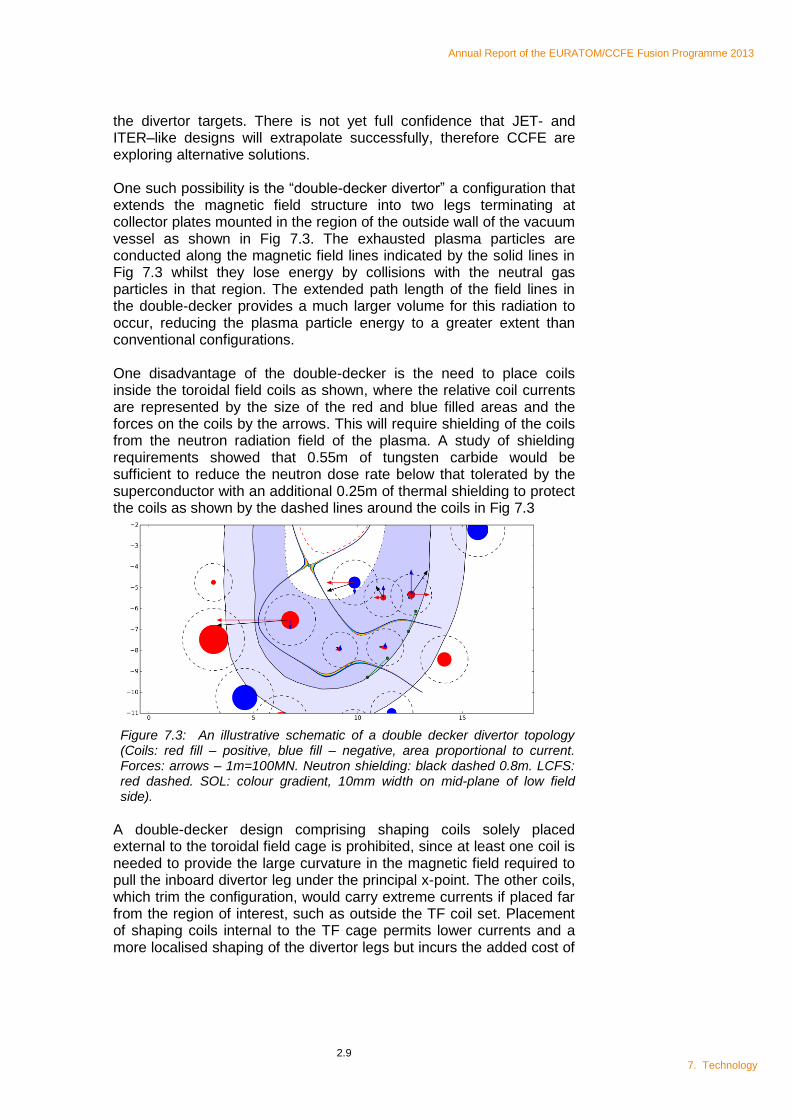
the divertor targets. There is not yet full confidence that JET- and ITER–like designs will extrapolate successfully, therefore CCFE are exploring alternative solutions. One such possibility is the “double-decker divertor” a configuration that extends the magnetic field structure into two legs terminating at collector plates mounted in the region of the outside wall of the vacuum vessel as shown in Fig 7.3. The exhausted plasma particles are conducted along the magnetic field lines indicated by the solid lines in Fig 7.3 whilst they lose energy by collisions with the neutral gas particles in that region. The extended path length of the field lines in the double-decker provides a much larger volume for this radiation to occur, reducing the plasma particle energy to a greater extent than conventional configurations. One disadvantage of the double-decker is the need to place coils inside the toroidal field coils as shown, where the relative coil currents are represented by the size of the red and blue filled areas and the forces on the coils by the arrows. This will require shielding of the coils from the neutron radiation field of the plasma. A study of shielding requirements showed that 0.55m of tungsten carbide would be sufficient to reduce the neutron dose rate below that tolerated by the superconductor with an additional 0.25m of thermal shielding to protect the coils as shown by the dashed lines around the coils in Fig 7.3
Figure 7.3: An illustrative schematic of a double decker divertor topology (Coils: red fill – positive, blue fill – negative, area proportional to current. Forces: arrows – 1m=100MN. Neutron shielding: black dashed 0.8m. LCFS: red dashed. SOL: colour gradient, 10mm width on mid-plane of low field side).
A double-decker design comprising shaping coils solely placed external to the toroidal field cage is prohibited, since at least one coil is needed to provide the large curvature in the magnetic field required to pull the inboard divertor leg under the principal x-point. The other coils, which trim the configuration, would carry extreme currents if placed far from the region of interest, such as outside the TF coil set. Placement of shaping coils internal to the TF cage permits lower currents and a more localised shaping of the divertor legs but incurs the added cost of
Annual Report of the EURATOM/CCFE Fusion Programme 2013
2.10 7 Technology
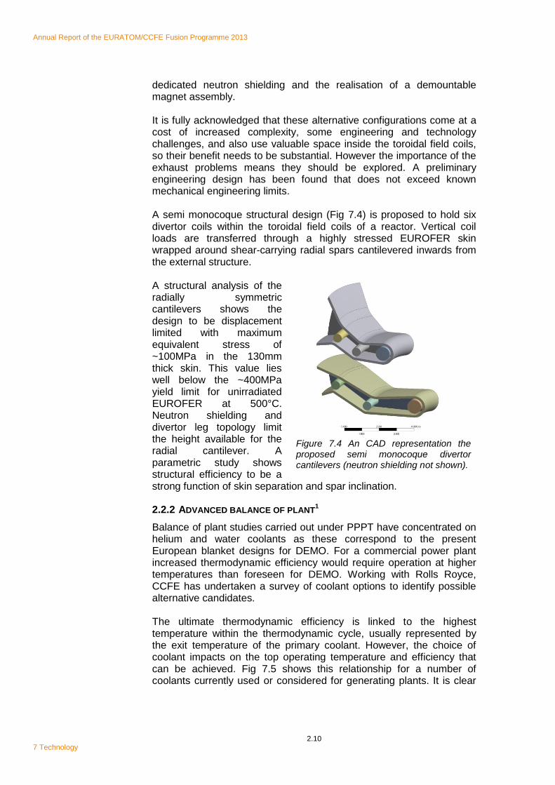
dedicated neutron shielding and the realisation of a demountable magnet assembly. It is fully acknowledged that these alternative configurations come at a cost of increased complexity, some engineering and technology challenges, and also use valuable space inside the toroidal field coils, so their benefit needs to be substantial. However the importance of the exhaust problems means they should be explored. A preliminary engineering design has been found that does not exceed known mechanical engineering limits. A semi monocoque structural design (Fig 7.4) is proposed to hold six divertor coils within the toroidal field coils of a reactor. Vertical coil loads are transferred through a highly stressed EUROFER skin wrapped around shear-carrying radial spars cantilevered inwards from the external structure. A structural analysis of the radially symmetric cantilevers shows the design to be displacement limited with maximum equivalent stress of ~100MPa in the 130mm thick skin. This value lies well below the ~400MPa yield limit for unirradiated EUROFER at 500°C. Neutron shielding and divertor leg topology limit the height available for the radial cantilever. A parametric study shows structural efficiency to be a strong function of skin separation and spar inclination. 2.2.2 ADVANCED BALANCE OF PLANT
1
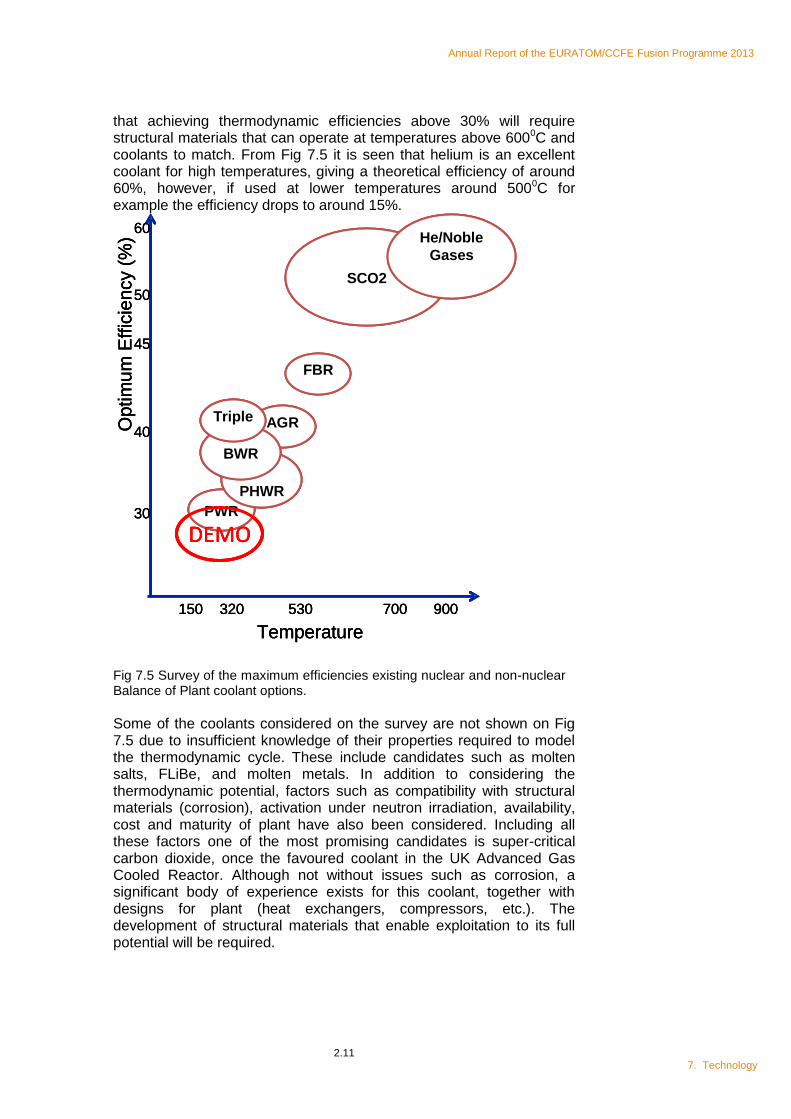
Balance of plant studies carried out under PPPT have concentrated on helium and water coolants as these correspond to the present European blanket designs for DEMO. For a commercial power plant increased thermodynamic efficiency would require operation at higher temperatures than foreseen for DEMO. Working with Rolls Royce, CCFE has undertaken a survey of coolant options to identify possible alternative candidates. The ultimate thermodynamic efficiency is linked to the highest temperature within the thermodynamic cycle, usually represented by the exit temperature of the primary coolant. However, the choice of coolant impacts on the top operating temperature and efficiency that can be achieved. Fig 7.5 shows this relationship for a number of coolants currently used or considered for generating plants. It is clear
Figure 7.4 An CAD representation the proposed semi monocoque divertor cantilevers (neutron shielding not shown).
Annual Report of the EURATOM/CCFE Fusion Programme 2013
2.11 7. Technology
AGR
FBR
SCO2
He/Noble
Gases
Temperature
150 320 700 900530
Optim
um
Effic
ien
cy (
%)
40
50
60
30
45
PWR
PHWR
BWR
Triple
DEMO
AGR
FBR
SCO2
He/Noble
Gases
Temperature
150 320 700 900530
Optim
um
Effic
ien
cy (
%)
40
50
60
30
45
Temperature
150 320 700 900530
Optim
um
Effic
ien
cy (
%)
40
50
60
30
45
PWR
PHWR
BWR
Triple
DEMOPWR
PHWR
BWR
Triple
DEMO
that achieving thermodynamic efficiencies above 30% will require structural materials that can operate at temperatures above 6000C and coolants to match. From Fig 7.5 it is seen that helium is an excellent coolant for high temperatures, giving a theoretical efficiency of around 60%, however, if used at lower temperatures around 5000C for example the efficiency drops to around 15%.
Fig 7.5 Survey of the maximum efficiencies existing nuclear and non-nuclear Balance of Plant coolant options.
Some of the coolants considered on the survey are not shown on Fig 7.5 due to insufficient knowledge of their properties required to model the thermodynamic cycle. These include candidates such as molten salts, FLiBe, and molten metals. In addition to considering the thermodynamic potential, factors such as compatibility with structural materials (corrosion), activation under neutron irradiation, availability, cost and maturity of plant have also been considered. Including all these factors one of the most promising candidates is super-critical carbon dioxide, once the favoured coolant in the UK Advanced Gas Cooled Reactor. Although not without issues such as corrosion, a significant body of experience exists for this coolant, together with designs for plant (heat exchangers, compressors, etc.). The development of structural materials that enable exploitation to its full potential will be required.
Annual Report of the EURATOM/CCFE Fusion Programme 2013
2.12 7 Technology
2.2.3 NEUTRON SOURCE1
Progress in the engineering design of the European DEMO by 2030 is dependent upon amassing a sufficiently informed database of material properties under fusion relevant irradiation conditions. To date only a small amount of data has been collected under irradiation by 14MeV neutrons and the need precede IFMIF with an early, reduced intensity neutron source is recognised in the EU Fusion Roadmap.
CCFE has continued to develop the FAFNIR (FAcility for Fusion Neutron Irradiation Research) concept with consortium partners Oxford, Birmingham and Manchester Universities and the STFC Rutherford Appleton Laboratory, specifically addressing the target engineering. FAFNIR is a 14MeV neutron source based on the reaction of a 40MeV deuterium beam on a carbon target. The intensity of the source depends on the deuterium beam current and achieving 30mA is the goal. This represents a power load on the carbon at the upper end of present capability, so design optimisation is essential.
An engineering analysis of the rotating target shows that for a given rotation speed, there is an optimum target size that minimises stress and temperature. The tensile stress is limited to around 37MPa for graphite and the temperature is limited to below 18000C by the evaporation rate. For a 30mA beam, simultaneously satisfying these conditions will require cooling of the target, possibly by helium gas.
FAFNIR remains a candidate for the European early neutron source and was presented at three international conferences in 2013, attracting attention from Korea and China.