2 computer organization and course structure … · computer organization and components ......
TRANSCRIPT
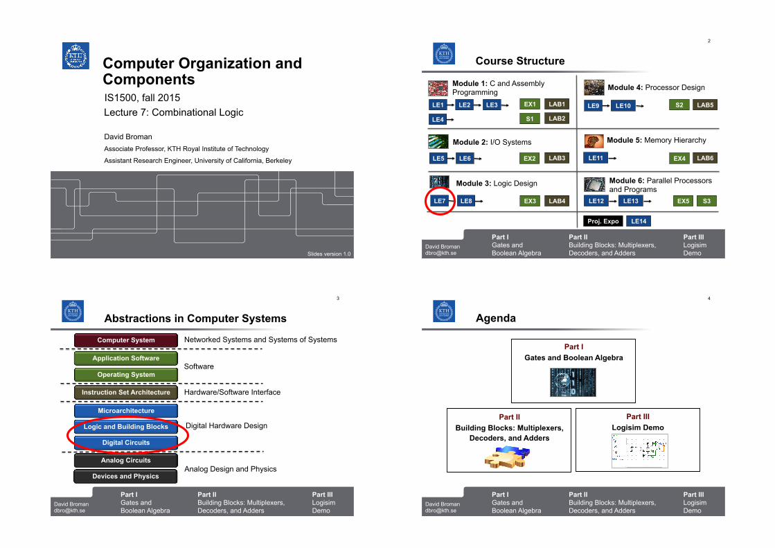
Computer Organization and Components
Lecture 7: Combinational Logic
David Broman Associate Professor, KTH Royal Institute of Technology
Assistant Research Engineer, University of California, Berkeley
IS1500, fall 2015
Slides version 1.0
Part I Gates and Boolean Algebra
Part II Building Blocks: Multiplexers, Decoders, and Adders
David Broman [email protected]
2
Part III Logisim Demo
Course Structure
Module 3: Logic Design
Module 4: Processor Design Module 1: C and Assembly Programming
Module 5: Memory Hierarchy Module 2: I/O Systems
Module 6: Parallel Processors and Programs
LE1 EX1 LAB1 LE2 LE3
LE4 S1 LAB2
LE5 LE6 EX2
LE7 LE8 EX3
LAB3
LAB4
LE9 LE10 S2 LAB5
LE11 EX4 LAB6
LE12 LE13 EX5 S3
Proj. Expo LE14
Part I Gates and Boolean Algebra
Part II Building Blocks: Multiplexers, Decoders, and Adders
David Broman [email protected]
3
Part III Logisim Demo
Abstractions in Computer Systems
Instruction Set Architecture
Microarchitecture
Logic and Building Blocks
Digital Circuits
Analog Circuits
Devices and Physics
Operating System
Application Software
Computer System Networked Systems and Systems of Systems
Software
Hardware/Software Interface
Digital Hardware Design
Analog Design and Physics
Part I Gates and Boolean Algebra
Part II Building Blocks: Multiplexers, Decoders, and Adders
David Broman [email protected]
4
Part III Logisim Demo
Agenda
Part II
Building Blocks: Multiplexers, Decoders, and Adders
Part I
Gates and Boolean Algebra
Part III
Logisim Demo
Part I Gates and Boolean Algebra
Part II Building Blocks: Multiplexers, Decoders, and Adders
David Broman [email protected]
5
Part III Logisim Demo
Part I
Gates and Boolean Algebra
Part I Gates and Boolean Algebra
Part II Building Blocks: Multiplexers, Decoders, and Adders
David Broman [email protected]
6
Part III Logisim Demo
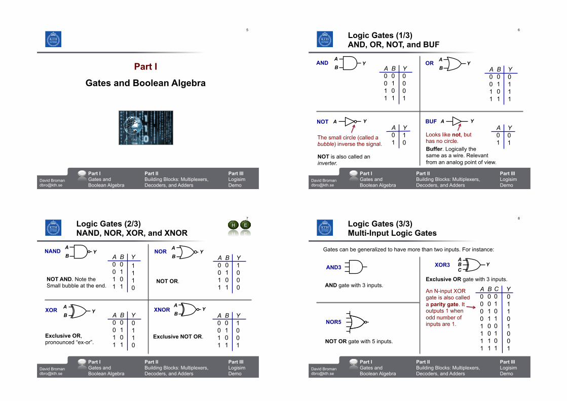
Logic Gates (1/3) AND, OR, NOT, and BUF
AND OR
NOT BUF
A 0 0 1 1
B 0 1 0 1
Y 00 0 1
B
AY
A 0 0 1 1
B 0 1 0 1
Y 01 1 1
A Y
B
AY
A YA 0 1
Y 10
A 0 1
Y 01
The small circle (called a bubble) inverse the signal.
NOT is also called an inverter.
Looks like not, but has no circle. Buffer. Logically the same as a wire. Relevant from an analog point of view.
Part I Gates and Boolean Algebra
Part II Building Blocks: Multiplexers, Decoders, and Adders
David Broman [email protected]
7
Part III Logisim Demo
Logic Gates (2/3) NAND, NOR, XOR, and XNOR
XOR XNOR
E
A 0 0 1 1
B 0 1 0 1
Y NAND
B
AY NOR
A 0 0 1 1
B 0 1 0 1
Y
B
AY
A 0 0 1 1
B 0 1 0 1
Y A 0 0 1 1
B 0 1 0 1
Y
NOT AND. Note the Small bubble at the end.
Exclusive OR, pronounced “ex-or”.
NOT OR.
H
B
AY
Exclusive NOT OR.
B
AY
11 1 0
10 0 0
01 1 0
1 00 1
Part I Gates and Boolean Algebra
Part II Building Blocks: Multiplexers, Decoders, and Adders
David Broman [email protected]
8
Part III Logisim Demo
Logic Gates (3/3) Multi-Input Logic Gates
XOR3
NOR5
AND3
Gates can be generalized to have more than two inputs. For instance:
AND gate with 3 inputs.
NOT OR gate with 5 inputs.
Exclusive OR gate with 3 inputs.
A 0 0 0 0 1 1 1 1
B 0 0 1 1 0 0 1 1
Y C 0 1 0 1 0 1 0 1
An N-input XOR gate is also called a parity gate. It outputs 1 when odd number of inputs are 1.
ABC
Y
0 1 1 0 1 0 0 1
Part I Gates and Boolean Algebra
Part II Building Blocks: Multiplexers, Decoders, and Adders
David Broman [email protected]
9
Part III Logisim Demo
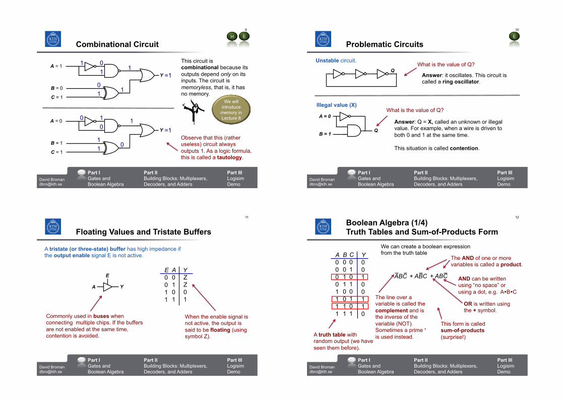
Combinational Circuit
This circuit is combinational because its outputs depend only on its inputs. The circuit is memoryless, that is, it has no memory.
E
A = 1
Y
B = 0
C = 1
1 0 1 1
=1 0 1
1
A = 0
Y
B = 1
C = 1
0 1 0
1 =1
1 1
0
We will introduce memory in Lecture 8
Observe that this (rather useless) circuit always outputs 1. As a logic formula, this is called a tautology.
H
Part I Gates and Boolean Algebra
Part II Building Blocks: Multiplexers, Decoders, and Adders
David Broman [email protected]
10
Part III Logisim Demo
Problematic Circuits
What is the value of Q?
Answer: it oscillates. This circuit is called a ring oscillator.
Q
Unstable circuit.
Illegal value (X)
A = 0
B = 1 Q
What is the value of Q?
Answer: Q = X, called an unknown or illegal value. For example, when a wire is driven to both 0 and 1 at the same time. This situation is called contention.
E
Part I Gates and Boolean Algebra
Part II Building Blocks: Multiplexers, Decoders, and Adders
David Broman [email protected]
11
Part III Logisim Demo
Floating Values and Tristate Buffers
A Y
EE 0 0 1 1
A 0 1 0 1
Y ZZ 0 1
A tristate (or three-state) buffer has high impedance if the output enable signal E is not active.
Commonly used in buses when connecting multiple chips. If the buffers are not enabled at the same time, contention is avoided.
When the enable signal is not active, the output is said to be floating (using symbol Z).
Part I Gates and Boolean Algebra
Part II Building Blocks: Multiplexers, Decoders, and Adders
David Broman [email protected]
12
Part III Logisim Demo
Boolean Algebra (1/4) Truth Tables and Sum-of-Products Form
We can create a boolean expression from the truth table A
0 0 0 0 1 1 1 1
B 0 0 1 1 0 0 1 1
Y 0 0 1 0 0 1 1 0
C 0 1 0 1 0 1 0 1
A truth table with random output (we have seen them before).
ABC + ABC + ABC
The line over a variable is called the complement and is the inverse of the variable (NOT). Sometimes a prime ‘ is used instead.
The AND of one or more variables is called a product.
AND can be written using “no space” or using a dot, e.g. A!B!C
OR is written using the + symbol.
This form is called sum-of-products (surprise!)
Part I Gates and Boolean Algebra
Part II Building Blocks: Multiplexers, Decoders, and Adders
David Broman [email protected]
13
Part III Logisim Demo
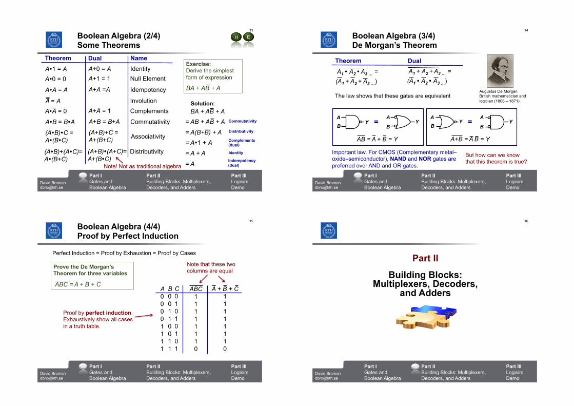
Boolean Algebra (2/4) Some Theorems
A!1 = A A+0 = A Identity A!0 = 0 Null Element
A!A = A
A+1 = 1
A+A =A Idempotency
A = A Involution A!A = 0 A+A = 1 Complements
A!B = B!A A+B = B+A Commutativity
E H
(A!B)!C = A!(B!C)
(A+B)+C = A+(B+C) Associativity
(A!B)+(A!C)= A!(B+C)
(A+B)!(A+C)= A+(B!C)
Distributivity
Theorem Dual Name Exercise: Derive the simplest form of expression
BA + AB + A
BA + AB + A
= AB + AB + A
= A(B+B) + A
= A!1 + A
= A + A
= A
Commutativity
Distributivity
Complements (dual)
Identity
Indempotency (dual)
Solution:
Note! Not as traditional algebra Part I Gates and Boolean Algebra
Part II Building Blocks: Multiplexers, Decoders, and Adders
David Broman [email protected]
14
Part III Logisim Demo
Boolean Algebra (3/4) De Morgan’s Theorem
A1 ! A2 ! A3 … =
(A1 + A2 + A3 …)
Theorem Dual A1 + A2 + A3 … =
(A1 ! A2 ! A3 …)
B
AY
Important law. For CMOS (Complementary metal–oxide–semiconductor), NAND and NOR gates are preferred over AND and OR gates.
The law shows that these gates are equivalent
But how can we know that this theorem is true?
B
AY=
AB = A + B = Y
B
AY
B
AY=
A+B = A B = Y
Augustus De Morgan British mathematician and logician (1806 – 1871).
Part I Gates and Boolean Algebra
Part II Building Blocks: Multiplexers, Decoders, and Adders
David Broman [email protected]
15
Part III Logisim Demo
Boolean Algebra (4/4) Proof by Perfect Induction
A 0 0 0 0 1 1 1 1
B 0 0 1 1 0 0 1 1
ABC 1 1 1 1 1 1 1 0
C 0 1 0 1 0 1 0 1
Perfect Induction = Proof by Exhaustion = Proof by Cases
Proof by perfect induction. Exhaustively show all cases in a truth table.
Prove the De Morgan’s Theorem for three variables
ABC = A + B + C A + B + C
1 1 1 1 1 1 1 0
Note that these two columns are equal
Part I Gates and Boolean Algebra
Part II Building Blocks: Multiplexers, Decoders, and Adders
David Broman [email protected]
16
Part III Logisim Demo
Part II
Building Blocks: Multiplexers, Decoders,
and Adders
Part I Gates and Boolean Algebra
Part II Building Blocks: Multiplexers, Decoders, and Adders
David Broman [email protected]
17
Part III Logisim Demo
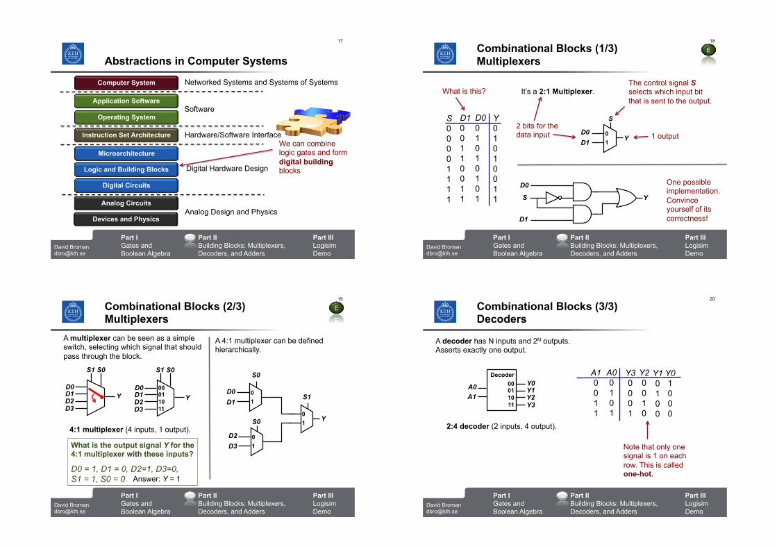
Abstractions in Computer Systems
Instruction Set Architecture
Microarchitecture
Logic and Building Blocks
Digital Circuits
Analog Circuits
Devices and Physics
Operating System
Application Software
Computer System Networked Systems and Systems of Systems
Software
Hardware/Software Interface
Digital Hardware Design
Analog Design and Physics
We can combine logic gates and form digital building blocks
Part I Gates and Boolean Algebra
Part II Building Blocks: Multiplexers, Decoders, and Adders
David Broman [email protected]
18
Part III Logisim Demo
Combinational Blocks (1/3)
E
Multiplexers
S 0 0 0 0 1 1 1 1
D1 0 0 1 1 0 0 1 1
Y 0 1 0 1 0 0 1 1
D0 0 1 0 1 0 1 0 1
What is this?
0
1
S
D0
D1
It’s a 2:1 Multiplexer.
2 bits for the data input 1 output
The control signal S selects which input bit that is sent to the output.
S
D0
D1
One possible implementation. Convince yourself of its correctness!
Y
Y
Part I Gates and Boolean Algebra
Part II Building Blocks: Multiplexers, Decoders, and Adders
David Broman [email protected]
19
Part III Logisim Demo
Combinational Blocks (2/3) Multiplexers
E
00 01 10 11
S1 S0
Y
A multiplexer can be seen as a simple switch, selecting which signal that should pass through the block.
Y
4:1 multiplexer (4 inputs, 1 output).
D0 D1 D2 D3
What is the output signal Y for the 4:1 multiplexer with these inputs?
D0 = 1, D1 = 0, D2=1, D3=0, S1 = 1, S0 = 0
D0 D1 D2 D3
A 4:1 multiplexer can be defined hierarchically.
0
1 D0
D1
Y
0
1
S0
0
1
D2
D3
S1
S0
Answer: Y = 1
S1 S0
Part I Gates and Boolean Algebra
Part II Building Blocks: Multiplexers, Decoders, and Adders
David Broman [email protected]
20
Part III Logisim Demo
Combinational Blocks (3/3) Decoders
Decoder 00 01 10 11
A decoder has N inputs and 2N outputs. Asserts exactly one output.
Y0
A1 A0 Y1
Y2 Y3
2:4 decoder (2 inputs, 4 output).
A1 0 0 1 1
Y3 0 0 0 1
A0 0 1 0 1
Y2 0 0 1 0
Y1 0 1 0 0
Y0 1 0 0 0
Note that only one signal is 1 on each row. This is called one-hot.
Part I Gates and Boolean Algebra
Part II Building Blocks: Multiplexers, Decoders, and Adders
David Broman [email protected]
21
Part III Logisim Demo
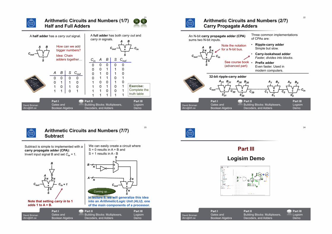
Arithmetic Circuits and Numbers (1/7) Half and Full Adders
A half adder has a carry out signal.
Idea: Chain adders together…
Cout +
A B
S
A full adder has both carry out and carry in signals.
+
A B
Cout
S
Cin
A
0 0 1 1
B
0 1 0 1
S
0 1 1 0
Cout
0 0 0 1
How can we add bigger numbers?
A
0 0 1 1 0 0 1 1
B
0 1 0 1 0 1 0 1
S
0 1 1 0
Cout
0 0 0 1
Cin
0 0 0 0 1 1 1 1
E H
1 0 0 1
0 1 1 1
Exercise: Complete the truth table
Part I Gates and Boolean Algebra
Part II Building Blocks: Multiplexers, Decoders, and Adders
David Broman [email protected]
22
Part III Logisim Demo
Arithmetic Circuits and Numbers (2/7) Carry Propagate Adders
An N-bit carry propagate adder (CPA) sums two N-bit inputs.
+
A B
Cout
S
Cin
N N
N
Note the notation for a N-bit bus.
Three common implementations of CPAs are:
• Ripple-carry adder Simple but slow.
• Carry-lookahead adder Faster, divides into blocks.
• Prefix adder Even faster. Used in modern computers.
See course book (advanced part)
32-bit ripple-carry adder
+
A31
Cout C30
B31
S31
+
A30
C29
B30
S30
+
A1
C0
B1
S1
+
A0
Cin
B0
S0
C1
Part I Gates and Boolean Algebra
Part II Building Blocks: Multiplexers, Decoders, and Adders
David Broman [email protected]
23
Part III Logisim Demo
Arithmetic Circuits and Numbers (7/7) Subtract
Subtract is simple to implemented with a carry propagate adder (CPA): Invert input signal B and set Cin = 1.
+
A
B
Cout
S
Cin
N N
N
= 1
Note that setting carry in to 1 adds 1 to A + B.
Coming up…
We can easily create a circuit where S = 0 results in A + B and S = 1 results in A - B
0
1
S
B
+
A
Cout
S
N
N
N
N
In lecture 9, we will generalize this idea into an Arithmetic/Logic Unit (ALU), one of the main components of a processor.
Part I Gates and Boolean Algebra
Part II Building Blocks: Multiplexers, Decoders, and Adders
David Broman [email protected]
24
Part III Logisim Demo
Part III
Logisim Demo
Part I Gates and Boolean Algebra
Part II Building Blocks: Multiplexers, Decoders, and Adders
David Broman [email protected]
25
Part III Logisim Demo
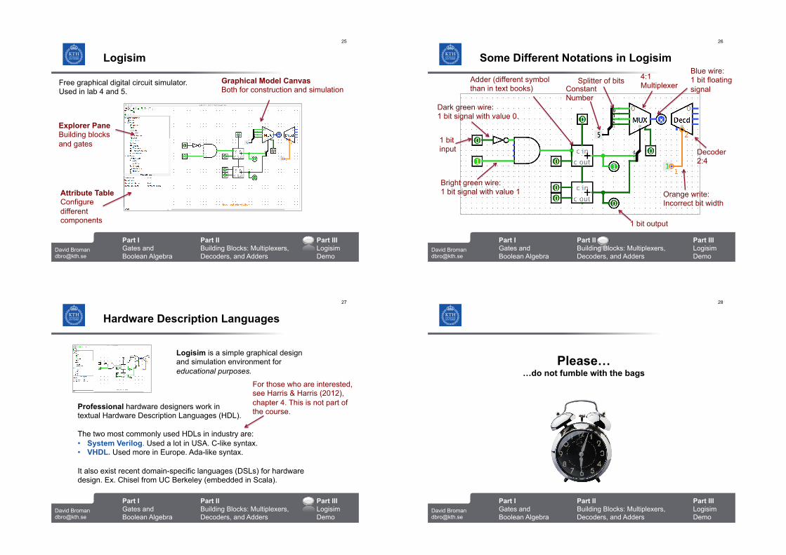
Logisim
Free graphical digital circuit simulator. Used in lab 4 and 5.
Graphical Model Canvas Both for construction and simulation
Attribute Table Configure different components
Explorer Pane Building blocks and gates
Part I Gates and Boolean Algebra
Part II Building Blocks: Multiplexers, Decoders, and Adders
David Broman [email protected]
26
Part III Logisim Demo
Some Different Notations in Logisim Blue wire: 1 bit floating signal
Dark green wire: 1 bit signal with value 0.
Bright green wire: 1 bit signal with value 1
Adder (different symbol than in text books)
1 bit input
1 bit output
Splitter of bits Constant Number
Orange write: Incorrect bit width
Decoder 2:4
4:1 Multiplexer
Part I Gates and Boolean Algebra
Part II Building Blocks: Multiplexers, Decoders, and Adders
David Broman [email protected]
27
Part III Logisim Demo
Hardware Description Languages
Logisim is a simple graphical design and simulation environment for educational purposes.
Professional hardware designers work in textual Hardware Description Languages (HDL). The two most commonly used HDLs in industry are: • System Verilog. Used a lot in USA. C-like syntax. • VHDL. Used more in Europe. Ada-like syntax. It also exist recent domain-specific languages (DSLs) for hardware design. Ex. Chisel from UC Berkeley (embedded in Scala).
For those who are interested, see Harris & Harris (2012), chapter 4. This is not part of the course.
Part I Gates and Boolean Algebra
Part II Building Blocks: Multiplexers, Decoders, and Adders
David Broman [email protected]
28
Part III Logisim Demo
Please…
…do not fumble with the bags
Part I Gates and Boolean Algebra
Part II Building Blocks: Multiplexers, Decoders, and Adders
David Broman [email protected]
29
Part III Logisim Demo
Reading Guidelines
Module 3: Logic Design Lecture 7: Combinational Logic Design • H&H Chapters 1.5, 2.1-2.4, 2.6, 2.8-2.9 Lecture 8: Sequential Logic Design • H&H Chapters 3.1-3.3 (not 3.2.7),
3.4.1-3.4.3, 5.2.1-5.2.2, 5.5.5
Reading Guidelines See the course webpage for more information.
Part I Gates and Boolean Algebra
Part II Building Blocks: Multiplexers, Decoders, and Adders
David Broman [email protected]
30
Part III Logisim Demo
Summary
• Combinational logic design: Output is directly dependent on input. There is no memory.
• Main components to remember: multiplexer, decoder, and adder.
• Next lecture is about sequential logic design; circuits with memory.
Thanks for listening!
Some key take away points: