2-14 project 1 infrastructure formatted
TRANSCRIPT

2.14-1
Chapter 2: Probable Impacts of Project 1, Shaft and Bypass Tunnel Construction
Section 2.14: Infrastructure
2.14-1 INTRODUCTION
This section analyzes the potential impacts of Project 1, Shaft and Bypass Tunnel Construction on utility services and infrastructure related to water supply, wastewater, and stormwater runoff. It describes existing service providers and conditions of existing services in the study areas, future conditions without Project 1, and any potential impacts of Project 1. The potential environmental impacts of Project 1 on stormwater runoff are also discussed.
Consequences of potential stormwater discharges to surface water resources during Project 1 are presented in Section 2.8, “Natural Resources and Water Resources.” Section 2.14 is organized as follows:
Section 2.14-2, “Methodology,” describes the methodology for assessing impacts associated with water supply, wastewater, and stormwater runoff and discusses the relevant regulations.
Sections 2.14-3.1 and 2.14-4.1 describe existing conditions in the west of Hudson and east of Hudson study areas, respectively.
Sections 2.14-3.2 and 2.14-4.2 describe conditions in the future without Project 1 (i.e., No Build) in the west of Hudson and east of Hudson study areas, respectively.
Sections 2.14-3.3 and 2.14-4.3 describe the potential impacts of Project 1 in the west of Hudson and east of Hudson study areas, respectively.
Section 2.14-4 presents conclusions.
2.14-2 METHODOLOGY
The relevant state, county, and town regulations for the design of water supply, wastewater and stormwater infrastructure required for Project 1, and the methodology and analysis of potential impacts in these areas are discussed below.
2.14-2.1 WATER SUPPLY
As described in Chapter 2.1, “Probable impacts of Project 1, Shaft and Bypass Tunnel Construction,” potable and non-potable water supply would be necessary at both the west and

Water for the Future Program: Delaware Aqueduct Rondout-West Branch Tunnel Repair FEIS
2.14-2
east connection sites throughout of Project 1. Potable water would be required for consumption, shower facilities, and the concrete batch plant process, while non-potable water would be necessary for equipment operation, dust control, and fire suppression. Once construction of Project 1 and Project 2B, Bypass Tunnel Connection and RWBT Inspection and Repair, including Wawarsing is complete, these water supply facilities would no longer be necessary at either connection site. Because water service mains are not currently available at either connection site for typical service connections, several alternatives for providing water to the two sites have been examined, and their feasibility and potential impacts are assessed in this section.
At the west connection site, three alternatives were investigated for potable and non-potable water: a new water supply well, a water main extension and new connection, and trucking water for on-site storage in tanks. At the east connection site, the three four alternatives investigated for providing potable water were: a new water supply well, treating water from the existing aqueduct, and trucking water for on-site storage, and a potential connection to the United Wappinger Water District (UWWD). All nNon-potable water required at the east connection site during Project 1 would be drawn from the existing aqueduct, or would be supplied using treated dewatering water, recycled stormwater, or water from the UWWD water main connection.
The following state and local regulations and guidelines were considered in determining the water supply design and permitting requirements for Project 1.
NEW YORK STATE DEPARTMENT OF HEALTH—SANITARY CODE
Design of potable water supply systems is governed by Public Health Law, Section 225, Title 10, Section 5–Drinking Water Supplies. The water supply permitting authority is delegated to the applicable county health departments for review and approval.
10 STATE STANDARDS—RECOMMENDED STANDARDS FOR WATER WORKS
The 10 State Standards provide general guidelines and standards for design of water supply systems in the Northeast region.
NEW YORK STATE BUILDING AND FIRE CODE
Proposed water storage tanks and on-site fire suppressions systems would be designed and operated in conformance with the New York State Building and Fire Code.
ORANGE COUNTY DEPARTMENT OF HEALTH
The Orange County Department of Health is responsible for enforcement of the regulations outlined in the Orange County Sanitary Code. The Sanitary Code includes the review and approval of potable water supply systems as well as sanitary systems.

Chapter 2: Probable Impacts of Project 1, Shaft and Bypass Tunnel Construction
Section 2.14: Infrastructure
2.14-3
DUTCHESS COUNTY DEPARTMENT OF HEALTH
The Dutchess County Department of Health is responsible for enforcement of the regulations outlined in the Dutchess County Sanitary Code. The Sanitary Code includes the review and approval of potable water supply systems as well as sanitary systems.
TOWN OF NEWBURGH—CONSOLIDATED WATER DISTRICT
A portion of the west connection site is located within the Consolidated Water District. The water main extension and service connection proposed for the west connection site would be designed in conformance with the Town of Newburgh’s standards for design and construction.
2.14-2.2 WASTEWATER
SANITARY WASTEWATER
Both connection sites would have restroom facilities for workers throughout the duration of Project 1. Three alternatives were investigated for managing sanitary wastewater: an on-site subsurface sewage treatment system, a package wastewater treatment plant, and a pump and haul process from a temporary holding tank.
The following regulations and guidelines were considered in determining the design and permitting requirements for the various Project 1 sanitary wastewater treatment alternatives.
NYSDEC Design Standards for Wastewater Treatment Works—Intermediate-Sized Sewerage Facilities
These design standards relate to subsurface sewage treatment and other wastewater treatment facilities. Sanitary discharges to groundwater of 1,000 to 10,000 gallons per day (gpd) of treated sanitary waste are permitted under State Pollutant Discharge Elimination System (SPDES) GP-0-05-001, and the wastewater treatment process for package treatment plants is permitted under SPDES Form NY-2A.
10 State Standards—Recommended Standards for Wastewater Facilities
These are general standards and guidelines for design of package treatment plants and other wastewater treatment systems in the Northeast.
New York State Department of Health—Sanitary Code
Design of wastewater treatment and conveyance systems is governed by Public Health Law, Section 225, Title 10. The permitting authority is delegated to the applicable county health departments for review and approval.
INDUSTRIAL WASTEWATER
During shaft and tunnel construction, dewatering operations would be necessary to keep the work areas at both connection sites dry for continued construction and worker safety. Because

Water for the Future Program: Delaware Aqueduct Rondout-West Branch Tunnel Repair FEIS
2.14-4
there are no existing wastewater treatment facilities in the vicinity of the connection sites, water would be pumped from the work areas to a treatment system and ultimately discharged to the adjacent stream at the west connection site, and to the Hudson River at the east connection site.
NYSDEC Regulations
Effluent standards for dewatering water are outlined in NYSDEC Part 703: Surface Water and Groundwater Quality Standards and Groundwater Effluent Limitations.
2.14-2.3 STORMWATER
Potential impacts associated with stormwater runoff at both connection sites would be alleviated through the implementation of erosion and sediment control practices and a stormwater management system designed in conformance with the following regulations.
NEW YORK STATE DEPARTMENT OF ENVIRONMENTAL CONSERVATION
General Permit for Stormwater Discharges from Construction Activities
Soil disturbances of greater than 1 acre require coverage under NYSDEC’s State Pollutant Discharge Elimination System General Permit for Stormwater Discharges from Construction Activities Permit No. GP-0-10-001 (SPDES GP-0-10-001). The design standards and guidance for erosion and sediment control and post-construction practices are outlined in the following documents:
New York Standards and Specifications for Erosion and Sediment Controls—last revised August, 2005
New York State Stormwater Management Design Manual (NYSSMDM)—last revised August, 2010
A Notice of Intent form must be completed and filed with NYSDEC Division of Water in Albany to obtain coverage under SPDES GP 0-10-001, and a letter of acknowledgement from NYSDEC is required prior to commencement of construction activities. Table 2.14-1 summarizes the NYSSMDM stormwater design criteria.
Table 2.14-1NYSDEC Uniform Sizing Criteria
Standard CriteriaWater Quality Volume (WQv)
WQv = Volume based on the 90 percent storm event.
Runoff Reduction Volume (RRv)
RRv = Reduction of the total WQv by application of green infrastructure techniques and SMPs to replicate pre-development hydrology.
Channel Protection (Cpv)
Cpv = 24 hour extended detention of post-developed 1-year, 24-hour storm event.
Overbank Flood (Qp)
Control the peak discharge from the 10-year storm to 10-year predevelopment rates.
Extreme Storm (Qf)
Control the peak discharge from the 100-year storm to 100-year predevelopment rates. Safely convey the 100-year storm event.

Chapter 2: Probable Impacts of Project 1, Shaft and Bypass Tunnel Construction
Section 2.14: Infrastructure
2.14-5
Modeling Methodology To analyze the stormwater runoff in existing and proposed conditions, a computer modeling program is used to model surface hydrology. The computer modeling program is a design tool used to evaluate and analyze the stormwater runoff from a site. The program is based on U.S. Department of Agriculture (USDA), Natural Resources Conservation Service (NRCS) Technical Releases TR20 and TR55. TR20 and TR55 are tools that were developed to calculate the volume and peak discharge rates of stormwater runoff for rainfall events over a 24-hour period. Runoff volumes and rates are calculated by determining the curve numbers (CN) and calculating the time of concentration (Tc) for each drainage area depending on the given rainfall value. The CN values are based on the TR55 table and the hydrologic soil group, cover type, hydrologic condition, and saturated soil runoff condition. The Tc represents the time it takes for surface water to travel to the hydraulically most distant point within the subcatchment area.
The following 24-hour rainfall values for Orange and Dutchess Counties, shown in Table 2.14-2, were used in the analysis. These values represent the rainfall distribution for various storm frequencies.
Table 2.14-2 Rainfall Values
Storm Event (Year) Rainfall Value (inches)1 2.80
10 5.00 100 8.00
Source: Northeast Regional Climate Center.
MULTI-SECTOR GENERAL PERMIT FOR STORMWATER DISCHARGES ASSOCIATED WITH INDUSTRIAL ACTIVITY
A concrete batch plant is proposed on the west connection site during the tunnel construction phase of Project 1. Therefore a Stormwater Pollution Prevention Plan (SWPPP) would be required in conformance with the NYSDEC SPDES Multi-Sector General Permit (MSGP) for Stormwater Discharges Associated with an Industrial Activity.
TOWN OF NEWBURGH—WEST OF HUDSON
Conformance with the Stormwater Management Code (Town Code Chapter 157) would be required. Typically, this can be achieved through conformance with the NYSDEC General Permit 0-10-001. Subsequent to the issuance of the DEIS, a draft SWPPP was prepared in accordance with the NYSSMDM and is included in the FEIS as Appendix 2.14-1. After the FEIS is issued, a revised SWPPP—which is currently being prepared, and upon which the FEIS conclusions are based—will be issued to address comments from the Town of Newburgh on the draft SWPPP, and to reflect the latest project design for the west connection site and the water main extension and dewatering pipeline segment along Route 9W. The Town of Newburgh—as a regulated, traditional land use MS4—would be is responsible for the review of a the SWPPP

Water for the Future Program: Delaware Aqueduct Rondout-West Branch Tunnel Repair FEIS
2.14-6
and completion of the MS4 acceptance form prior to filing of the Notice of Intent with NYSDEC.
TOWN OF WAPPINGER—EAST OF HUDSON
All land development activities require conformance with the Stormwater Management and Erosion and Sediment Control Code (Town Code Chapter 213, Article I). Subsequent to the issuance of the DEIS, a draft SWPPP would be was prepared in accordance with the NYSSMDM and is included in the FEIS as Appendix 2.14-2. After the FEIS is issued, a revised SWPPP—which is currently being prepared, and upon which the FEIS conclusions are based—will be issued to address comments raised by the Town of Wappinger on the draft SWPPP, and to reflect the latest project design for the east connection site. The Town of Wappinger—as a regulated, traditional land use MS4—would be is responsible for the review of a the SWPPP and completion of the MS4 acceptance form prior to filing of the Notice of Intent with the NYSDEC.
2.14-3 WEST OF HUDSON
2.14-3.1 EXISTING CONDITIONS—WEST OF HUDSON
WEST CONNECTION SITE
Water Supply
The west connection site is mostly undeveloped; therefore, new water service would be required to support Project 1 construction activities. The municipally-owned and operated water supply main is located south on Route 9W approximately 1,100 feet south of the existing southern driveway to the west connection site. There is a well on the west connection site, and the existing adjacent properties have wells for potable water supply.
Wastewater
As with water service, an existing public sanitary sewer service is not located in the vicinity of the west connection site. Adjacent parcels and local residences are served by subsurface sewage treatment systems.
Stormwater
The west connection site is primarily undeveloped, and there are no existing stormwater facilities on-site. Stormwater runoff generally flows from west to east toward the existing on-site stream (described below). The site is steeply sloped, with a 200-foot elevation change from Route 9W to the western boundary. The eastern portion of the site has a road frontage on Route 9W and several vacant buildings, including a former restaurant and bar, and two single-family homes with a barn, a cinderblock outbuilding, and several trailers. The western portion of the site is vacant. Stormwater runoff from a portion of the adjacent off-site uphill area flows across the site.
Chapter 2: Probable Impacts of Project 1, Shaft and Bypass Tunnel Construction
Section 2.14: Infrastructure
2.14-7
A NYSDEC Use Class C stream (New York State Waters Index #H-103-1-3, a third-order tributary to Lattintown Creek) runs through the southeastern portion of the site, which then flows under Route 9W and ultimately into Lattintown Creek just upstream of its confluence with the Hudson River. Accordingly, the site falls within the Hudson River watershed. The on-site stream is not a 303(d) listed water body, nor is the site part of a protected watershed.
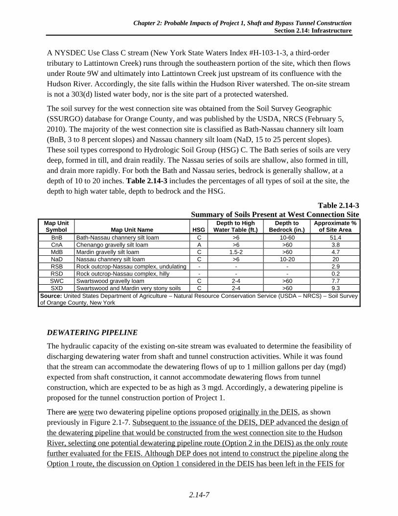
The soil survey for the west connection site was obtained from the Soil Survey Geographic (SSURGO) database for Orange County, and was published by the USDA, NRCS (February 5, 2010). The majority of the west connection site is classified as Bath-Nassau channery silt loam (BnB, 3 to 8 percent slopes) and Nassau channery silt loam (NaD, 15 to 25 percent slopes). These soil types correspond to Hydrologic Soil Group (HSG) C. The Bath series of soils are very deep, formed in till, and drain readily. The Nassau series of soils are shallow, also formed in till, and drain more rapidly. For both the Bath and Nassau series, bedrock is generally shallow, at a depth of 10 to 20 inches. Table 2.14-3 includes the percentages of all types of soil at the site, the depth to high water table, depth to bedrock and the HSG.
Table 2.14-3Summary of Soils Present at West Connection Site
Map Unit Symbol Map Unit Name HSG
Depth to High Water Table (ft.)
Depth to Bedrock (in.)
Approximate % of Site Area
BnB Bath-Nassau channery silt loam C >6 10-60 51.4 CnA Chenango gravelly silt loam A >6 >60 3.8 MdB Mardin gravelly silt loam C 1.5-2 >60 4.7 NaD Nassau channery silt loam C >6 10-20 20 RSB Rock outcrop-Nassau complex, undulating - - - 2.9 RSD Rock outcrop-Nassau complex, hilly - - - 0.2 SWC Swartswood gravelly loam C 2-4 >60 7.7 SXD Swartswood and Mardin very stony soils C 2-4 >60 9.3
Source: United States Department of Agriculture – Natural Resource Conservation Service (USDA – NRCS) – Soil Survey of Orange County, New York
DEWATERING PIPELINE
The hydraulic capacity of the existing on-site stream was evaluated to determine the feasibility of discharging dewatering water from shaft and tunnel construction activities. While it was found that the stream can accommodate the dewatering flows of up to 1 million gallons per day (mgd) expected from shaft construction, it cannot accommodate dewatering flows from tunnel construction, which are expected to be as high as 3 mgd. Accordingly, a dewatering pipeline is proposed for the tunnel construction portion of Project 1.
There are were two dewatering pipeline options proposed originally in the DEIS, as shown previously in Figure 2.1-7. Subsequent to the issuance of the DEIS, DEP advanced the design of the dewatering pipeline that would be constructed from the west connection site to the Hudson River, selecting one potential dewatering pipeline route (Option 2 in the DEIS) as the only route further evaluated for the FEIS. Although DEP does not intend to construct the pipeline along the Option 1 route, the discussion on Option 1 considered in the DEIS has been left in the FEIS for

Water for the Future Program: Delaware Aqueduct Rondout-West Branch Tunnel Repair FEIS
2.14-8
reference purposes. In March 2012, DEP submitted a Joint Application to USACE for an individual permit for the dewatering pipeline and other project elements, and to NYSDEC with supplemental information to facilitate its review in the context of Protection of Waters and 401 Water Quality Certification approvals.
Both pipeline routes would traverse approximately 1,400 feet southward along Route 9W, continuing approximately 1,900 feet eastward along Old Post Road, and an additional 2,200 feet eastward along River Road. At the southern turn along River Road, Option 1 would continue approximately 2,500 feet eastward, ultimately discharging into the Hudson River; Option 2 would continue approximately 3,000 feet southward along River Road, ultimately discharging to the tidal portion of a stream, near its confluence with the Hudson River. The majority of both pipeline route options would be constructed under the existing asphalt pavement, with the approximate 2,500 feet for the last portion of Option 1 being lawn or meadow.
2.14-3.2 FUTURE WITHOUT PROJECT 1, SHAFT AND BYPASS TUNNEL CONSTRUCTION—WEST OF HUDSON
WEST CONNECTION SITE
In the future without Project 1, the west connection site would remain in its current condition, and no changes to water supply, wastewater, or stormwater are expected.
DEWATERING PIPELINE
In the future without Project 1, the dewatering pipeline would not be constructed and no disturbance would take place along either of the proposed routes.
2.14-3.3 PROBABLE IMPACTS OF PROJECT 1, SHAFT AND BYPASS TUNNEL CONSTRUCTION—WEST OF HUDSON
WEST CONNECTION SITE
This following section discusses the probable impacts due to the infrastructure built in support of the construction activities related to the west connection site. The section is organized as follows:
Water Supply
Sanitary Wastewater
Industrial Wastewater - SPDES Industrial Discharge Permit NY-2C (Shaft and Tunnel Construction Dewatering)
Stormwater
Multi-Sector General Permit for Stormwater Discharges Associated with Industrial Activity.

Chapter 2: Probable Impacts of Project 1, Shaft and Bypass Tunnel Construction
Section 2.14: Infrastructure
2.14-9
Water Supply
Potable water is required for the restrooms, showers, and laundry facilities to be used by construction workers at the west connection site. Based on the expected number of workers the average potable water demand for the west connection site would be approximately 7,400 gallons per day.
Potential sources of potable water supply that were investigated included a new on-site well, water delivery and storage on-site, and connection to the municipal water system. A new well would require disinfection, and possibly treatment, because potable water would be provided to more than 25 people. The on-site storage and distribution of potable water delivered by a certified bulk supplier would also require disinfection and operation by certified personnel. In light of these constraints, it was determined that the preferred alternative for potable water supply would be a connection to the municipal water system via a water main extension along Route 9W, as described in greater detail below.
The existing Town of Newburgh water main does not extend north beyond the intersection of Old Post Road and Route 9W. Therefore, approximately 1,400 feet of new water main extending north along Route 9W is proposed. The proposed water main would be designed and constructed in accordance with the requirements of the Town of Newburgh Consolidated Water District and applicable design standards. In discussions with the Consolidated Water District staff, it is understood that there may not be adequate pressure and flow to convey water from Route 9W to the top of the west connection site, an approximately 200-foot elevation change. Therefore, a water booster pump station would be constructed on-site to help provide the necessary flow to the work area.
Non-potable water needs, including equipment operation, dust control, and fire suppression, would be met using potable water from the water main extension described above, as well as with treated dewatering water or stormwater recycled on the west connection site. The maximum potential non-potable water demand would be approximately 251,000 gpd. A 30,000-gallon non-potable water storage tank to be used for fire suppression would also be constructed on-site.
A well monitoring program would be implemented for the existing well to remain on the west connection site and the well located at 5505 Route 9W, Newburgh. Coordination would be undertaken with the off-site property owner to install a well filter and well level sensor and provide filter maintenance. If any of the wells being monitored are impacted by the construction of Project 1, such that the well production or the water quality is less than satisfactory, an alternate supply of potable water of up to 300 gallons per each impacted household per day would be provided until the issue has been sufficiently resolved.
Sanitary Wastewater
The following wastewater systems were considered:
A package treatment plant with a surface discharge;
A subsurface sewage treatment system; and

Water for the Future Program: Delaware Aqueduct Rondout-West Branch Tunnel Repair FEIS
2.14-10
A holding tank to be pumped and hauled.
The proposed sanitary flows under Project 1, assuming 90 percent of average potable water usage from restrooms, showers and laundry facilities would be returned as sanitary wastewater, would be approximately 6,700 gpd. The holding tank was selected as the preferred alternative due to its relative simplicity and because a permanent sewage treatment system would not be required at the west connection site.
Sanitary sewage would be conveyed to the sanitary holding tank, which would be pumped out on a regular schedule by a certified sanitary waste hauler. A permit for the tank would not be required from NYSDEC; however, review and approval by the regional NYSDEC Division of Water would be required. Review and approval from the Town of Newburgh and Orange County Health Department may also be required. The following would be provided to each regulatory entity for their approval:
Evidence of an agreement with a professional hauler for disposal of the waste;
A written statement from the wastewater treatment plant owner/operator that it can accept the waste;
Holding tank design that includes
- a capacity equal to at least twice the volume of the waste to be generated between anticipated removal dates, within a minimum of 1,000 gallons;
- floats and alarms to minimize the potential for discharges to the surface;
- measures to minimize the potential for freezing; and
- odor control measures.
Industrial Wastewater - SPDES Industrial Discharge Permit NY-2C (Shaft and Tunnel Construction Dewatering)
During Project 1’s shaft and tunnel construction phases, dewatering of the shaft and tunnel work areas would be required. Potential pollutants in the waste stream would consist of suspended solids from the shaft excavation and bypass tunnel boring operations; connector tunnel excavation; muck removal; concreting of the shaft, bypass tunnel, and connector tunnel; vehicle washing; and operation of the concrete batch plant.
During shaft construction, the maximum flow from the construction dewatering would be approximately 1 mgd and would discharge to the stream adjacent to the west connection site. During tunnel construction, the maximum tunnel dewatering rate would be approximately 3 mgd, which would be conveyed through the proposed dewatering pipeline to the Hudson River. (The same pipeline would be used during Project 2B to unwater the RWBT before connecting the bypass tunnel, with a maximum flow rate of 10 mgd over approximately 2 weeks.)
All dewatering water and construction-related water would be treated to meet surface water effluent standards., and an individual SPDES NY-2C permit would be obtained A SPDES NY-2C permit application for industrial facilities was submitted to NYSDEC Region 3 in February

Chapter 2: Probable Impacts of Project 1, Shaft and Bypass Tunnel Construction
Section 2.14: Infrastructure
2.14-11
2012 for the proposed dewatering facility on the west connection site. The water treatment facility would be designed to meet the effluent limitations shown in Table 2.14-4.
Table 2.14-4 Effluent Parameters
Parameter Effluent RequirementSettleable solids 0.1 ml/l Total suspended solids 25 mg/l (daily average)
45 mg/l (daily maximum) Oils and grease 15 mg/l (daily maximum) pH range 6.5-8.5
Water from the shaft and tunnel construction, vehicle washing, muck dewatering, and operation of the concrete batch plant would be collected and piped to the water treatment facility. The treated effluent would then be conveyed to the on-site stream. The water would be sampled and tested to ensure compliance with the permitting requirements.
Stormwater
Following an introduction to the potential impacts related to stormwater and common practices to minimize these impacts, stormwater management measures that would be employed during Project 1 construction are discussed below. They are:
Erosion and sediment control;
Inspection and maintenance; and
Stormwater management practices.
Introduction Impacts to stormwater runoff can result from changes in land use, creation of impervious surfaces, and changes in grading. As vegetation is removed and the amount of impervious surfaces increases, the quality of stormwater runoff decreases, impacting receiving water bodies. Because of changes in land use and increase in impervious surfaces, a smaller volume of stormwater infiltrates into the soil, increasing volume and peak flow of stormwater runoff.
Potential impacts to surface water quality and quantity associated with construction activities are alleviated with various stormwater treatment practices. The NYSSMDM offers relevant guidance, with a focus on conserving natural areas, reducing impervious cover, and better integrating stormwater treatment.
Green infrastructure practices are now a required element of stormwater treatment systems, with the post-developed condition closely replicating pre-development conditions as much as possible. Green infrastructure techniques, involving infiltration and groundwater recharge among others, are employed to replicate pre-development hydrology conditions.
The following explains the design of the proposed stormwater management system for Project 1 at the west connection site.

Water for the Future Program: Delaware Aqueduct Rondout-West Branch Tunnel Repair FEIS
2.14-12
Erosion and Sediment Control The potential impacts associated with construction activities for Project 1 include sediment deposition, rilling and erosion, and the potential for causing turbidity within receiving water bodies. To address these potential impacts due to the disturbance of approximately 20 acres, erosion and sediment control plans have been developed. It is anticipated that the west connection site would require a waiver to allow disturbance of greater than 5 acres. Subsequent to the issuance of the DEIS, a 5-acre waiver request was submitted in February 2012 to the Town of Newburgh, the regulated traditional land use MS4, and is currently under review. Project phasing would be developed to minimize the amount of disturbance in each phase, and a detailed sequence of construction activities and implementation of erosion and sediment control practices would be developed for each of the project phases. The project development phases that include most of the land disturbance have been divided into seven stages, and the sequence of construction activities that the contractor would follow has been defined. Subsequent to the issuance of the DEIS, DEP developed and submitted to NYSDEC and the Town of Newburgh a draft SWPPP with erosion and sediment controls, stormwater management measures, and vegetative stabilization measures. Implementation of erosion and sediment control measures as part of the SWPPP would minimize potential impacts to water quality associated with stormwater runoff during land-disturbing activities.
It is anticipated that the following practices would be implemented throughout the construction activities to minimize the potential impacts associated with the disturbance:
Protect vegetation
Stabilized construction entrance/exit
Straw bales and/or Silt fence
Stone check dams
Storm drain inlet protection
Material stockpile protection
Gravel surface construction area
Stone outlet sediment trap
Dust control
Temporary stabilization (such as rolled erosion control blankets, seeding and mulching or soil stabilizers)
Sump pit
Dewatering
Perimeter dike/swale
Temporary sediment basin
Materials handling precautions

Chapter 2: Probable Impacts of Project 1, Shaft and Bypass Tunnel Construction
Section 2.14: Infrastructure
2.14-13
All potential pollutants, such as petroleum products and chemicals, would be properly stored in designated areas to minimize contact with precipitation.
Inspection and Maintenance Inspection and maintenance of the proposed stormwater management features would be conducted to ensure that the erosion and sediment control practices that are part of the SWPPP continue to be effective in preventing sediment and other pollutants from entering the stormwater system. As a part of the SWPPP inspection and maintenance activities during construction, an Erosion and Sediment Control Inspection Report would be updated and kept on-site.
Inspections would need to be conducted by the qualified inspector once every seven days, according to the schedule required by the SPDES GP 0-10-001. The inspection schedule would be increased to twice per week when land disturbance is greater than five acres. During each inspection, the qualified inspector would record the areas of disturbance, deficiencies in erosion and sediment control practices, required maintenance, and areas of temporary or permanent stabilization. The need for modifications to the Erosion and Sediment Control Plan would be identified and implemented immediately.
All maintenance would be completed in accordance with the New York State Standards and Specifications for Erosion and Sediment Control. All erosion and sediment control measures would be maintained in good working order; if repairs are found to be necessary, the qualified inspector would notify the DEP, the contractor, and the construction manager of any necessary corrective actions within one business day. The contractor (or subcontractor) would need to begin implementing the corrective actions within one business day of this notification and need to complete the corrective actions in a reasonable time frame.
Stormwater Management Practices
An analysis of the existing and proposed conditions would be has been performed to fully evaluate the effects of Project 1 on stormwater runoff. A hydrologic modeling program would be was used to determine existing, or pre-development runoff volumes and peak flow conditions. This same modeling program would be was used to develop the proposed, or post-development, stormwater management system. The proposed system would be has been designed and modeled to demonstrate that the peak flows do not cause downstream flooding. each of the design analysis point are equal to the pre-development peak flow rates after construction.
The proposed stormwater management system would be has been designed to capture and treat stormwater runoff for treatment of the Water Quality Volume (WQv). Once the west connection site has been stabilized, the temporary sediment basin located at the entrance to the site would be converted to a permanent stormwater treatment basin an approximately 14-foot-deep micropool extended detention basin. The basin would include a forebay to allow preliminary settling of coarse sediment. The outlet control structure would be modified in accordance with the NYSSMDM, and the basin would be vegetated with various native plant species. to maintain a permanent 6-foot depth of water or micropool. A 10- to 15-foot-wide aquatic bench surrounding

Water for the Future Program: Delaware Aqueduct Rondout-West Branch Tunnel Repair FEIS
2.14-14
the micropool was designed with semi-aquatic vegetation for additional pollutant removal and nutrient uptake.
The existing site has less than an acre of impervious surface, including the existing houses and driveways. Project 1 would result in an increase in temporary impervious surfaces due to the construction of the access road, parking areas, concrete batch plant, and construction laydown areas. The stormwater management system would be has been designed in conformance with the intent of the NYSSMDM stormwater sizing criteria listed in Table 2.14-1. The goal is to treat the WQv, the volume of stormwater runoff from the 90 percent rainfall event, in a stormwater treatment practice such as a stormwater pond, infiltration basin, or created wetland would be met through the design of the micropool extended detention basin. To address the stormwater quantity or peak flows from the 1-, 10-, and 100-year storm events, a stormwater management practice would be was designed to detain the stormwater runoff peak flows to match pre-developed conditions. Please note that although the draft SWPPP included in Appendix 2.14-1 indicates a slight increase in stormwater runoff peak flows over pre-developed conditions for the 100-year storm, this increase has since been eliminated. This will be reflected in the revised SWPPP which will be issued after issuance of the FEIS, and upon which the conclusions of the FEIS are based. As mentioned above, the revised SWPPP will also address comments from the Town of Newburgh on the draft SWPPP, and will reflect the latest project design for the west connection site and the water main extension and dewatering pipeline segment along Route 9W.
In addition to peak flow analysis, runoff reduction volume (RRv) green infrastructure practices, including tree pits and a bioretention basin, have been incorporated into the design. that may be incorporated into the design. may include
Open channels;
Rain gardens;
Tree pits; and
Rain tanks or cisterns for water reuse.
The post construction inspection and maintenance program would be implemented after the completion of all construction activities and final stabilization of the project site. Additional discussion of the post construction inspection and maintenance program is provided in Section 5.5, “Infrastructure.”
Multi-Sector General Permit for Stormwater Discharges Associated with Industrial Activity
As discussed above, a concrete batch plant is proposed on the west connection site during the tunnel construction phase of Project 1. For current planning purposes, the batch plant would occupy an area of approximately 15,000 square feet, and would provide grout during the placement of the pre-cast concrete segments by the tunnel boring machine (TBM), as well as providing concrete for the final bypass tunnel lining, connector tunnels, and other project elements. Concrete required for shaft construction would be trucked in from an outside source.

Chapter 2: Probable Impacts of Project 1, Shaft and Bypass Tunnel Construction
Section 2.14: Infrastructure
2.14-15
Potential sources of stormwater pollution related to the construction and operation of the concrete batch plant include spilled aggregate, cement, admixture, and vehicle washing. Likely pollutants of concern include total suspended solids (TSS), pH level, chemical oxygen demand (COD), lead, iron, zinc, oil and gas.
A SWPPP would be developed in conformance with the requirements of the NYSDEC SPDES Multi-Sector General Permit (MSGP) for Stormwater Discharges Associated with an Industrial Activity. A Pollution Prevention Team would be identified within the SWPPP to help address spill prevention and responses, staff training, inspection and maintenance, sampling, and testing. The SWPPP would identify stormwater treatment practices that would provide settling and filtering of the finer particulates, including cement, sediment, and hydrocarbons. Wash water from the vehicle wash station and stormwater runoff from the concrete batch operation would be collected and conveyed to the dewatering treatment facilities.
Non-structural best management practices (BMPs), such as good housekeeping, preventive maintenance, spill response measures, and street sweeping, would be outlined in the SWPPP to satisfy the permit requirements.
In addition to structural and non-structural stormwater practices, the SWPPP would include training requirements, quarterly visual inspections, dry weather inspections, and annual benchmark pollutant sampling. An annual certification report would be completed and submitted to the NYSDEC during each year of construction activities.
DEWATERING PIPELINE
The majority of the proposed dewatering pipeline would be located within the existing roadbed or adjacent shoulder, and potential impacts to stormwater runoff would only occur during construction as a result of the open excavation to install the pipeline. An erosion and sediment control plan would be designed to address potential impacts to stormwater runoff, and may include the following practices:
Sump pit;
Portable sediment tank;
Silt fence; and
Inlet protection.
When approaching stream crossings, construction of the dewatering pipeline would be accomplished by the jack and bore methodusing trenchless construction techniques. The proposed pipeline would be constructed below the stream bed to avoid any short or long-term impacts to the stream. Once the design of the complete dewatering pipeline is finalized, the draft SWPPP for the west connection site, water main extension, and dewatering pipeline segment along Route 9W would be modified. The impacts associated with construction of the water main extension and dewatering pipeline would be temporary and not result in an increase in impervious surfaces.

Water for the Future Program: Delaware Aqueduct Rondout-West Branch Tunnel Repair FEIS
2.14-16
2.14-4 EAST OF HUDSON
2.14-4.1 EXISTING CONDITIONS—EAST OF HUDSON
WATER SUPPLY
There is currently no public potable water supply on or in close proximity to the east connection site, and the site is not located within a water supply district. The surrounding parcels and residences are served by private wells. There are two wells located at Shaft 6; however, they have very low yield and are currently classified as non‐potable.
The closest potable water purveyor to the east connection site with excess capacity is the Town of Wappinger water supply (UWWD).
WASTEWATER
As with water service, an existing public sanitary sewer service is not located in the vicinity of the east connection site. Adjacent parcels and local residences are served by subsurface sewage treatment systems. The existing restroom facilities at the east connection site are served by a small septic system adjacent to the Hudson River Pump Station; this system serves fewer than five people per day.
STORMWATER
The east connection site is approximately 20.1 acres and is developed with a number of DEP and contractor-related structures. At the main entrance, there is a guard booth, temporary field offices and parking facilities associated with the ongoing rehabilitation of Shaft 6. The construction activities, impervious surfaces, and stormwater infrastructure associated with this rehabilitation are covered under an existing SPDES permit. A portion of the impervious surfaces associated with the rehabilitation would be utilized for Project 1 and 2A, and then removed upon completion of the current proposed program. The stormwater infrastructure includes an underground sand filter, SMP 1, constructed at the upper parking lot, west of the existing Shaft 6 building, to treat stormwater runoff and convey flow the existing blow-off chamber. A second underground sand filter, SMP 2, located in the lower parking area in the southwest corner of the project site, treats stormwater runoff and conveys it downstream to the existing stormwater outfall adjacent to the Hudson River. The underground vaults were designed as the on-site SMPs in accordance with the NYSDEC’s Stormwater Management Design Manual (2003). Other DEP facilities on the east connection site include the Shaft 6 superstructure, Hudson River Pump Station, power supply facilities (substation), roads and parking areas.
The east connection site is bordered by a New York Power Authority (NYPA) substation to the north and northeast, residences to the east and south, and a Metro-North rail line to the west. Access to the east connection site is currently provided by a driveway at the southern portion of the site.

Chapter 2: Probable Impacts of Project 1, Shaft and Bypass Tunnel Construction
Section 2.14: Infrastructure
2.14-17
The existing off-site area, including the NYPA property, which drains onto the east connection site is approximately 22.8 acres. Approximately 16.7 acres of the 20.1-acre existing site drains to the Hudson River to the west of the property, by way of existing outfalls. Areas along the northern and southwestern boundaries of the east connection site drain by sheet flow to other existing stormwater conveyances.
The Hudson River is a Class A stream; however, it is not part of the 303(d) listed water bodies for potential pollutants associated with stormwater runoff.
Table 2.14-5 includes the percentage of each type of soil at the site, the depth to high water table, depth to bedrock and the HSG. Approximately 60 percent of the site is comprised of Udorthents soils (Ud), which were excavated during the construction of the existing Delaware aqueduct, and which drain somewhat slowly. The Dutchess-Cardigan complex consists of an intricate pattern of very deep Dutchess soils that drain readily, and moderately deep Cardigan soils formed in glacial till deposits, which also drain readily. The Nassau-Rock outcrop complex consists of approximately 45 percent Nassau soils, which are shallow, drain very rapidly, and are formed in till, as well as 30 percent rock outcrop, and 25 percent other soils. None of the soils identified at the site are classified as highly erodible.
Table 2.14-5Summary of Soils Present at East Connection Site
Map Unit Symbol Map Unit Name HSG
Depth to High Water Table (ft.)
Depth to Bedrock (in.)
Approximate % of Site Area
DwB Dutchess-Cardigan complex, undulating, rocky
B Rock
outcrop (D)>6 20-40 30
NxE Nassau-Rock outcrop complex, steep
C Rock
outcrop (D)>6 10-20 10
Ud Udorthents, smoothed A/D >3 >60 60
Source: United States Department of Agriculture – Natural Resource Conservation Service (USDA – NRCS) –Soil Survey of Dutchess County, New York.
2.14-4.2 FUTURE WITHOUT PROJECT 1, SHAFT AND BYPASS TUNNEL CONSTRUCTION—EAST OF HUDSON
EAST CONNECTION SITE
In the future without Project 1, the ongoing rehabilitation of Shaft 6 would be completed and the site would be restored to its operational condition.
2.14-4.3 PROBABLE IMPACTS OF PROJECT 1, SHAFT AND BYPASS TUNNEL CONSTRUCTION—EAST OF HUDSON
This following section discusses the probable impacts due to the infrastructure built in support of the construction activities related to the west connection site. The section is organized as follows:

Water for the Future Program: Delaware Aqueduct Rondout-West Branch Tunnel Repair FEIS
2.14-18
Water Supply
Sanitary Wastewater
Industrial Wastewater - SPDES Industrial Discharge Permit NY-2C (Shaft and Tunnel Construction Dewatering)
Stormwater
WATER SUPPLY
Potable water is required for the restrooms, showers, and laundry facilities to be used by construction workers at the east connection site. The average potable water demand for the east connection site would be approximately 5,200 gpd.
Potential sources of potable water supply that were investigated included the following: (1) constructing a new on-site well; (2) water delivery and storage on-site; (3) and treating water from the existing aqueduct; (4) and a potential connection to the UWWD. Review of the existing on-site water supply wells and geotechnical borings indicate that the groundwater supply yield would not be sufficient to meet the projected demand. Furthermore, the New York State Department of Health (NYSDOH) public water supply well setback requirements to certain activities makes the construction of a new well on the east connection site infeasible. Accordingly, the only the feasible options for potable water supply are water delivery and storage on-site, and treating water from the existing aqueduct, and a potential connection to the UWWD. In either case, water would be pumped into a water storage tank.
The first two feasible options would require water to be pumped into a storage tank. In addition, in accordance with Part 5, Subpart 5-1, Section 5-1.1 of NYSDOH Sanitary Code, based on a system that would serve at least 25 of the same individuals for at least six months, the water supply system would be classified as a Non-Transient Non-Community Water System (NTNCWS). Therefore a Potable Water Source (PWS) would need to be established, including the requirement for a designated system operator, as well as disinfection if the water source were to be a certified bulk potable water purveyor, and disinfection and treatment if the water source were to be the existing aqueduct. The design of the potable water system would be in conformance with the NYSDOH Sanitary Code, Dutchess County DOH Sanitary Code, and the 10 State Standards.
The third feasible option to provide a reliable potable water supply to the east connection site would involve the potential construction of a water main between the site and the UWWD, prior to construction of the east connection shaft under Project 1. The nearest UWWD trunk main is located approximately 3.5 miles northeast of from the east connection site and is primarily supplied from a series of deep gravel wells positioned along Wappingers Creek. The district has sufficient excess capacity capable of meeting DEP’s approximate maximum daily demand. A connection to the UWWD, would allow for a reliable water supply to the east connection site during construction of Projects 1, 2A, and 2B. Once construction is complete, this water main

Chapter 2: Probable Impacts of Project 1, Shaft and Bypass Tunnel Construction
Section 2.14: Infrastructure
2.14-19
could potentially provide the town with a connection to the RWBT and a long-term source of potable water.
The proposed water main connection, and subsequent use of the water main and any distribution lines, additional piping, or treatment necessary for the distribution of water within the Town of Wappinger would be subject to a separate environmental review. The construction and environmental review of this water main connection would be undertaken by the Town of Wappinger. If this option is chosen, construction of the water main would be similar to a typical installation along public right-of-ways, and would cover approximately 100 linear feet per day. The impacts associated with construction of the water main would be temporary and not result in an increase in impervious.
Non-potable water needs, including equipment operation, dust control, and fire suppression, would be met using water from the existing aqueduct, as well as with treated dewatering water, or recycled stormwater, or water from the from UWWD water main connection. recycled on the east connection site. The maximum potential non-potable water demand would be approximately 80,000 gpd. A 30,000-gallon non-potable water storage tank to be used for fire suppression would also be constructed on-site.
A well monitoring program would be implemented for properties located within 500 feet horizontal distance of the centerline of the east connection site shaft and properties located at 179, 191, 192, 198, 212, 216, 217, 219, and 225 River Road North in the Town of Wappinger. Coordination would be undertaken with these property owners to install well filters and well level sensors and provide filter maintenance services. If any of the wells being monitored are impacted by the construction of Project 1, such that the well production or the water quality is less than satisfactory, an alternate supply of potable water of up to 300 gallons per impacted household per day would be provided until the issue has been sufficiently resolved.
SANITARY WASTEWATER
As mentioned above, the existing sanitary system for the Shaft 6 site serves fewer than five people per day. This existing system does not have the capacity to accept flows that would be generated by Project 1 which, assuming 90 percent of the average potable water usage for restrooms, showers and laundry facilities would be returned as sanitary wastewater, would be approximately 4,700 gpd. Accordingly, the following new wastewater systems were considered:
A package treatment plant with a surface discharge;
A subsurface sewage treatment system; and
A holding tank to be pumped and hauled.
The holding tank was selected as the preferred alternative due to its relative simplicity and the fact that a new permanent sewage treatment system would not be required at the east connection site.

Water for the Future Program: Delaware Aqueduct Rondout-West Branch Tunnel Repair FEIS
2.14-20
Sanitary sewage from the bathrooms, showers, and laundry facilities would be conveyed to the sanitary holding tank, which would be pumped out on a regular schedule by a certified sanitary waste hauler. A permit for the tank would not be required from NYSDEC; however, review and approval by the regional NYSDEC Division of Water would be required. Review and approval from the Town of Wappinger and Dutchess County Health Department may also be required. The following would be provided to each regulatory entity for their approval:
Evidence of an agreement with a professional hauler for disposal of the waste;
A written statement from the wastewater treatment plant owner/operator that it can accept the waste;
Holding tank design that includes
- a capacity equal to at least twice the volume of the waste to be generated between anticipated removal dates, within a minimum of 1,000 gallons;
- floats and alarms to minimize the potential for discharges to the surface;
- measures to minimize the potential for freezing; and
- odor control measures.
INDUSTRIAL WASTEWATER - SPDES INDUSTRIAL DISCHARGE PERMIT NY-2C
During the shaft construction phase of Project 1 at the east connection site, dewatering would be required. The potential pollutants in the waste stream would consist of suspended solids from the shaft and connector tunnel excavation, muck removal, concreting of the shaft and connector tunnel, and vehicle washing. The maximum flow would be approximately 1 mgd and would discharge to the Hudson River.
All dewatering water and construction-related water would be treated to meet surface water effluent standards, and an individual SPDES NY-2C permit would be obtained. The water treatment facility would be designed to meet the following effluent limitations shown in Table 2.14-6.
Table 2.14-6 Effluent Parameters
Parameter Effluent RequirementSettleable solids 0.1 ml/l
Total suspended solids 25 mg/l (daily average)
45 mg/l (daily maximum) Oils and grease 15 mg/l (daily maximum)
pH range 6.5-8.5
Water from the shaft and connector tunnel construction, muck dewatering, and vehicle washing would be collected and piped to the water treatment facility. The treated effluent would then be conveyed to the existing blow-off chamber and outfall to the Hudson River. The water would be sampled and tested to ensure compliance with the permitting requirements. It is likely that the existing individual SPDES permit for the blow-off chamber would be modified to include flow

Chapter 2: Probable Impacts of Project 1, Shaft and Bypass Tunnel Construction
Section 2.14: Infrastructure
2.14-21
from the water treatment facility. An individual SPDES NY-2C permit application was submitted to NYSDEC in February 2012, and is currently under review.
Finally, during the tunnel connection phase, unwatering of the existing aqueduct at approximately 10 mgd would be necessary, and would be covered under the existing SPDES Permit for unwatering the aqueduct at this location.
STORMWATER
Following an introduction to the potential impacts related to stormwater and common practices to minimize these impacts, stormwater management measures that would be employed during Project 1 construction are discussed below. They are:
Erosion and sediment control;
Inspection and maintenance; and
Stormwater management practices.
Introduction
Impacts to stormwater runoff can result from changes in land use, creation of impervious surfaces, and changes in grading. As vegetation is removed and the amount of impervious surfaces increases, the quality of stormwater runoff decreases, impacting receiving water bodies. Because of changes in land use and increase in impervious surfaces, a smaller volume of stormwater infiltrates into the soil, increasing volume and peak flow of stormwater runoff.
Potential impacts to surface water quality and quantity associated with construction activities are alleviated with various stormwater treatment practices. The NYSSMDM offers relevant guidance, with a focus on conserving natural areas, reducing impervious cover, and better integrating stormwater treatment.
Green infrastructure practices are now a required element of stormwater treatment systems, with the post-developed condition closely replicating pre-development conditions as much as possible. Green infrastructure techniques, involving infiltration and groundwater recharge among others, are employed to replicate pre-development hydrology conditions.
The following sub-sections explain the design of the proposed stormwater management system for Project 1 at the east connection site.
Erosion and Sediment Control
The potential impacts associated with construction activities for Project 1 include sediment deposition, rilling and erosion, and the potential for causing turbidity within receiving water bodies. To address these potential impacts, erosion and sediment control plans have been developed. Off-site stormwater runoff would be diverted around the work area at the east connection site to avoid impacts from pollutants generated by the construction activities. A temporary sediment basin would be constructed to treat on-site stormwater runoff by capturing

Water for the Future Program: Delaware Aqueduct Rondout-West Branch Tunnel Repair FEIS
2.14-22
and treating it through settling and filtering. The sediment basin would connect into the existing stormwater management system and convey stormwater to the Hudson River via the existing blow-off chamber outfall. Subsequent to the issuance of the DEIS, DEP developed and submitted to NYSDEC and the Town of Wappinger a draft SWPPP with erosion and sediment controls, stormwater management measures, and vegetative stabilization measures. Implementation of erosion and sediment control measures as part of the SWPPP would minimize potential impacts to water quality associated with stormwater runoff during land-disturbing activities.
It is anticipated that the following additional practices would be implemented throughout the construction activities to minimize the potential impacts associated with the disturbance:
Stabilized construction entrance/exit
Straw bales and/or silt fence
Storm drain inlet protection
Material stockpile protection
Dust control
Temporary stabilization (rolled erosion control blankets, seeding and mulching, and soil stabilizers)
Sump pit
Dewatering
Perimeter dike/swale
Materials handling precautions
All potential pollutants, such as petroleum products, chemicals, etc, would be properly stored in designated areas in order to minimize contact with precipitation.
Inspection and Maintenance
Inspection and maintenance of the proposed stormwater management features would be conducted to ensure that the erosion and sediment control practices that are part of the SWPPP continue to be effective in preventing sediment and other pollutants from entering the stormwater system. As a part of the SWPPP inspection and maintenance activities during construction, an Erosion and Sediment Control Inspection Report would be updated and kept on-site.
Inspections would need to be conducted by the qualified inspector every seven days according to the schedule required by the SPDES GP 0-10-001. During each inspection, the qualified inspector would record the areas of disturbance, deficiencies in erosion and sediment control practices, required maintenance, and areas of temporary or permanent stabilization. The need for modifications to the Erosion and Sediment Control Plan would be identified and implemented immediately.
All maintenance would need to be completed in accordance with the New York State Standards and Specifications for Erosion and Sediment Control. All erosion and sediment control measures would be maintained in good working order; if repairs are found to be necessary, the qualified

Chapter 2: Probable Impacts of Project 1, Shaft and Bypass Tunnel Construction
Section 2.14: Infrastructure
2.14-23
inspector would notify DEP, the contractor and the construction manager of any necessary corrective actions within one business day. The contractor (or subcontractor) would need to begin implementing the corrective actions within one business day of this notification and need to complete the corrective actions in a reasonable time frame.
Stormwater Management Practices
Stormwater runoff discharges from the east connection site would be discharged into the Hudson River, a tidal water body. The Hudson River is not on the 303(d) list of water bodies impaired by stormwater runoff or within a watershed improvement strategy area. Therefore, stormwater quantity or the channel protection volume, overbank flood protection, and flood control sizing criteria would not be required. However, post-construction stormwater quality treatment practices would be required.
The Portions of the existing stormwater management system would be utilized for conveyance. where feasible. The proposed stormwater management system would be has been designed to capture and treat stormwater runoff for treatment of the WQv.
Since there would be a net reduction in impervious area in the post-construction condition for the portions of the east connection site that flow to the two underground sand filters, the plan for permanent stormwater quality control would be as follows:
Existing sand filters SMP 1 and SMP 2 would be retrofitted with new inlet piping to accommodate the changes to the contributing drainage areas during the various construction phases.
SMP 1 and SMP 2, in the lower parking area, would remain in service and would continue to treat the remaining impervious area that flows to the practices.
A bioretention/rain garden bioretention basin is proposed planned to treat the WQv from the new east connection site shaft (Shaft 6B) and associated access road.
The post construction inspection and maintenance program would be implemented after the completion of all construction activities and final stabilization of the project site. Additional discussion of the post construction inspection and maintenance program is provided in Section 5.5, “Infrastructure.”
2.14-4 CONCLUSIONS
2.14-4.1 WEST OF HUDSON
Based on the information and analysis presented above, Project 1 would not result in any significant adverse impacts in the areas of water supply, wastewater, or stormwater runoff.
While the proposed new impervious surfaces and changes in land use would potentially increase peak stormwater runoff flows, decrease infiltration, and increase pollutant concentrations in stormwater runoff, the proposed stormwater mitigation measures would minimize potentially adverse impacts. The post-development stormwater flows would be attenuated to the pre-

Water for the Future Program: Delaware Aqueduct Rondout-West Branch Tunnel Repair FEIS
2.14-24
development flow conditions, thus decreasing erosion potential and improving water quality. The runoff reduction volume would be achieved through the use of on-site tree pits plantings and pits, a bioretention basin, open channels, and an approximately 14-foot-deep micropool extended detention basin infiltration basins. Overall, the proposed stormwater practices would re-introduce infiltration, provide filtering, and promote evapotranspiration.
2.14-4.2 EAST OF HUDSON
Based on the information and analysis presented above, Project 1 would not result in any significant adverse impacts in the areas of water supply, wastewater, or stormwater.
While the proposed new impervious surfaces and changes in land use would potentially increase peak stormwater runoff flows, decrease infiltration, and increase pollutant concentrations in stormwater runoff, the proposed stormwater mitigation measures would minimize potentially adverse impacts. The runoff reduction volume would be achieved through the use of and a bioretention basin and underground sand filters. tree pits Overall, the proposed stormwater practices would re-introduce infiltration, provide filtering, and promote evapotranspiration.