1tripr xd combo operator’s manual part #125-030-01
TRANSCRIPT

1tRIPr XD ComboOperator’s Manual
Part #125-030-01

INTRODUCTION
Built for today’s larger farms, the drawn Orthman 1tRIPr® XD Combo offers the additional efficiency of fertilizer carrying capacity integrated in large-frame drawn designs, combined with a planter attachment feature to enable a true single-pass operation. The Orthman 1tRIPr® XD Combo is a great addition to the modern high horsepower farms.
12 row 1tRIPr® XD Combo
The Orthman 1tRIPr® XD Combo comes standard with Orthman 1tRIPr® row units and can be equipped with dual 500 gallon fertilizer tanks to fully utilize the 1tRIPr® XD Combo as a true single-pass machine. The Orthman 1tRIPr® XD Combo is available in four and six wheel configurations to carry a wide variety of implement sizes. A wide stance creates stability in the field as well as during transport. High lift clearance allows for adequate clearance in rough terrain. To increase lifting capacity, optional lift wheels (2) are available for addition to four-lift wheel machines.
For information regarding the 1tRIPr® row units, refer to the 1tRIPr® operator’s manual provided with the machine.
This manual is considered to be an integral component of the 1tRIPr® XD Combo and is designed to educate the owner and/or operator(s) regarding safety, operation, maintenance, troubleshooting, and component identification. All personnel involved in the operation of this implement are responsible for reading and understanding entire manual content. This manual is designed to keep the operator safe and knowledgeable as well as prolong the life of the implement and maximize field efficiency. This manual should accompany the implement if it were ever to be sold.
We would like to thank you for placing your confidence in Orthman Mfg., Inc. Your 1tRIPr® XD Combo is manufactured to meet the highest standards and is built with precision and strength to increase your agricultural operation’s dependability and profitability.
Thank you for choosing Orthman.
1 - 1

INTRODUCTION
To The Dealer:Inspect the implement thoroughly after assembly to be certain it is functioning properly before delivering it to the customer. The following checklist is a reminder of points to cover. Check off each item as it is found satisfactory or after proper adjustment is made.
Pre-Delivery Checklist
1. All Hardware properly tightened.
2. Lubrication of grease fittings.
3. All decals properly located and readable.
4. All implement tools and options are installed and set.
5. Check overall condition of implement.
6. Make sure Operator’s manual is included.
Date Set Up. Signature.
DeliveryReview the operator’s manual with the customer. Explain the following:
1. Introduce the machine to the customer. Give the customer this manual and encourage them to read it.2. Make the customer aware of all the safety precautions that must be exercised when using and transporting this machine.3. Make customer aware of the different tooling options available.4. This machine does not come set to run in the field from the factory. The Field settings section in this manual is meant to help set the machine for optimal performance. Explain all operating adjustments.5. Explain to the customer that the life expectancy of this machine depends on regular maintenance as directed in this manual.6. Tell the customer to use the proper tools for service and make them aware of Orthman parts availability.7. Write machine model number and serial number in the spaces provided below.
Date delivered. Signature.
Model Number.
Serial Number.
1 - 2

INTRODUCTION INTRODUCTION
TABLE OF CONTENTS
INTRODUCTION General Information -XD Combo. ....................................................................................................................................................1 - 1
Delivery Checklist. ..........................................................................................................................................................................1 - 2
Warranty Information ....................................................................................................................................................................1 - 3
Table of Contents ............................................................................................................................................................................1 - 4
IMPORTANT SAFETY INFORMATION Farm Safety.....................................................................................................................................................................................2 - 1
Your Protection - Equipment Safety - Safety Alert Symbol ............................................................................................................2 - 3
Signal Words - Shutdown and Storage ...........................................................................................................................................2 - 4
Safe Transport - Warning and Safety Lights ...................................................................................................................................2 - 5
Safe Operation - No Riders ..............................................................................................................................................................2 - 6
Practice Safe Maintenance..............................................................................................................................................................2 - 7
Practice Safe Maintenance - Prepare for Emergencies ...................................................................................................................2 - 8
Anhydrous Ammonia - Liquid Fertilizer Precautions - Safety Never Hurts .....................................................................................2 - 9
Safety Decals ................................................................................................................................................................................2 - 10
Orthman Decals and Orthman Serial Tag ......................................................................................................................................2 - 14
PREPARATION AND SETUP Toolbar Component Identification ..................................................................................................................................................3 - 1
Tongue Component Identification ..................................................................................................................................................3 - 2
Machine Lift Component Identification ..........................................................................................................................................3 - 3
Light Kit Component Identification ................................................................................................................................................ 3 -4
Shipping Configuration...................................................................................................................................................................3 - 5
Preparing the Toolbar/Machine to Tractor Connection ...................................................................................................................3 - 6
Machine to Secondary Implement Connection ...............................................................................................................................3 - 8
TOOLING OPTIONS AND INSTALLATION Tongue Tab .....................................................................................................................................................................................4 - 1
Liquid Fertilizer Tank Package ........................................................................................................................................................4 - 2
LIft Tire Scraper Package ................................................................................................................................................................4 - 3
Nurse Tank HItch .............................................................................................................................................................................4 - 4
1 - 41 - 3
WARRANTY
Orthman warrants each new wholegood product to be free from defects in manufactured components and workmanship. This warranty is applicable only for the normal service life expectancy of the product or components, not to exceed twenty-four (24) consecutive months from date of purchase of the new Orthman product to the original purchaser.
Purchased components installed by Orthman (blades, bearings, controls, hoses, wheels, coulters, cylinders, fittings, etc.) shall be warranted by the respective manufacturer for a period of twelve (12) consecutive months from date of delivery of the new Orthman product to the original purchaser.
A completed online Warranty Registration for the original purchaser must be received by Orthman to activate warranty coverage. Non-receipt of warranty registration may void warranty coverage. The Orthman warranty is non-transferable.
Genuine Orthman replacement parts and components will be warranted for ninety (90) days from date of purchase, or the remainder of the original equipment warranty period, whichever is greater.
All warranty work is to be performed by an authorized Orthman dealer at the repairing dealer’s location, unless otherwise approved by Orthman.
Under no circumstances, will this warranty cover any merchandise or component thereof, which, in the opinion of Orthman, has been subjected to misuse, unauthorized modifications or alteration, accident, collision with obstruction/ground, or if repairs have been made with parts other than those obtainable through Orthman.
Orthman warranty policies do not cover travel expenses, after-hours field/service time, overnight expenses, or expenses not related to regular shop labor rates or parts replaced during actual warranty repair. Orthman reserves the right to adjust warranty labor credits to believed normal repair times as directed by state law(s).
This warranty shall be limited to repairing or replacing, free of charge to the purchaser, any part, which Orthman’s judgment shows evidence of such defect. Additionally, the defective part(s) shall be returned within thirty (30) days from the date of failure to Orthman through the dealer or distributor from whom the product was purchased or repaired; transportation charges prepaid.
This warranty shall not be interpreted to render Orthman liable for injury or damages of any kind or nature to person or property. This warranty does not extend to the loss of crops, loss of delay in harvesting/planting, or any expense or loss incurred for labor, substitute machinery, rental, or any subsequent reasons thereof.
Except as set forth above, Orthman shall have no obligation or liability of any kind on account of its equipment and shall not be liable for special or consequential damages. Orthman makes no other warranty, expressed or implied, and, specifically disclaims any implied warranty or merchantability or fitness for a particular purpose. Some states or provinces do not permit limitations or exclusions of implied warranties or incidental or consequential damages, so the limitations or exclusion in this warranty may not apply. This warranty is subject to any existing conditions of supply, which may directly affect ability to obtain materials or manufacture replacement parts.
Orthman reserves the right to make improvements in design or changes in specifications at any time, without incurring any obligation to owners of units previously sold; to include, but not limit to engineering prototype machines. No one is authorized to alter, modify, or enlarge this warranty nor the exclusions, limitations, and reservations.
© Copyright 2014Orthman Manufacturing Inc.Lexington, NebraskaAll rights reserved.
Orthman provides this manual without warranty of any kind, expressed or implied. This manual reflects the product at the time of publication. All information within is based upon current information on the publication date. Orthman assumes no responsibility for damages incurred due to the use of the illustrations, information, and specifications within this publication.

SAFETY INFORMATIONINTRODUCTIONFarm Safety
Contrary to the popular image of fresh air and peaceful surroundings, a farm is not a hazard-free work setting.Every year, thousands of farm workers are injured and hundreds more die in farming accidents. According to the National Safety Council, agriculture is the most hazardous industry in the nation.
How You Can Improve Farm Safety
You can start by increasing your awareness of farming hazards and making a conscious effort to prepare for emergency situations including fires, vehicle accidents, electrical shocks from equipment and wires, and chemical exposures. Be especially alert to hazards that may affect children and the elderly. Minimize hazards by carefully selecting the products you buy to ensure that you provide good tools and equipment. Always use seat belts when operating tractors, and establish and maintain good housekeeping practices. Here are some other steps you can take to reduce illnesses and injuries on the farm:
• Read and follow instructions in equipment operator’s manuals and on product labels.• Inspect equipment routinely for problems that may cause accidents.• Discuss safety hazards and emergency procedures with your workers.• Install approved rollover protective structures, protective enclosures, or protective frames on tractors.• Make sure that guards on farm equipment are replaced after maintenance.• Review and follow instructions in material safety data sheets (MSDSs) and on labels that come with chemical products and communicate information on these hazards to your workers.
Health and Safety Hazards on Farms
Farm workers including farm families and migrant workers are exposed to hazards such as the following:
Danger Potential Effect or Injury PreventionChemicals/Pes-ticides
Skin and respiratory injury or death MSDS and proper Personal Protective Equipment. Review Manufacturers data sheets
Cold Illness, Frostbite or death Dress properly for the day.
Dust Respiratory injury or explosive combinations Be aware of your surroundings and activity
Electricity Shock, burns, fire, death Use a qualified professional for wiring dangerous electrical devices. Never overload a circuit. Replace damaged electrical devices or cords. Electrical tape will not insulate you from injury.
Grain bins, Silos Entrapment, Suffocation, Explosion from formation of dangerous gases and poisoning.
Make sure the bin is properly ventilated and maintained. Never walk the grain.
Hand tools Injury including cuts abrasions, electrocution, strains, sprains and death
Make sure you hand tools are in good condition. Never leave a damaged tooling accessible for someone else to use.
Highway traffic Collisions resulting in injury or death Follow regulations, stay alert. Avoid alcohol and use of communication devices while driving
Lifting & lifting devices
Back injury, sprains, strains. Falling material resulting in being struck or crushed by heavy material
Use proper lifting technique. Get help when the load is too heavy. Inspect chains, straps or cables routine-ly to make sure they are in good condition.
Livestock handling Serious injury or death resulting from being pinned struck or trampled.
Always make sure you have adequate room and an escape route
Machinery/Equip-ment
Cuts, abrasions, amputations, death. Thoroughly read and understand your Owners Equipment Manual. Never operate the equipment without guards in place. Make sure the equipment can not be energized or otherwise put into operation while you are working on it.
Manure pits Explosion from formation of dangerous gases. Suffo-cation. Poisoning
Proper maintenance.
Mud Sprains, strains, entrapment and suffocation. Eye injury and skin irritation.
Proper Personal Protective Equipment. In some conditions a “Spotter” may be needed.
Noise Hearing damage Personal Protective Equipment.
Ponds Drowning Wear a life preserver and make sure help is readily available.
Slips/Trips/Falls Sprains, strains, back and neck injury, bone breaks or death
Keep work area free from clutter and organized. If working on anything elevated make sure you have appropriate guarding and/or fall protection such as a harness and lanyard.
Sun/Heat Sun burn, Heat Stroke, shock, death Use common sense on excessively hot days, use sun screen, wear a hat and stay hydrated.
Toxic gases Skin and respiratory injury or death. Explosion. MSDS and proper Personal Protective Equipment. Review Manufacturers data sheets
Tractors Cuts, abrasions, amputations, death. Thoroughly read and understand your Owners Equipment Manual. Never operate the equipment without guards in place. Anti-roll over devices.
Wells Electrocution, amputation, death Avoid contact with water while working on an electrical device. Always be sure the equipment can/will not be energized during repair or maintenance. Make sure all guarding is in place.
Severe Weather Electrocution, “struck by” injuries, death Move to a safe place. Lightening, hail and tornadoes are unpredictable.
Orthman Manufacturing, Inc. does not limit the potential effects or injuries nor prevention measures to those listed above. They are provided solely as a guideline to making your farm life safer. Always consult your Owner/Operators Manual for specific tool and equipment safety requirements.
2 - 1
TABLE OF CONTENTS
FIELD SETTINGS Field Operation ................................................................................................................................................................................5 - 1 Bar Stand Placement ...............................................................................................................................................................5 - 1 Rigid Operation - Wing Leveling ..............................................................................................................................................5 - 2 Toolbar Height and Orientation ................................................................................................................................................5 - 3
HYDRAULICS Main Hydraulic Manifold Block Port Identification..........................................................................................................................6 - 1 Combo Lift Hydraulic Manifold Block and Flow Divider Port Identification ....................................................................................6 - 2 Machine Fold Hydraulic Hose Routing .............................................................................................................................................6 - 3 Machine Lift Hydraulic Hose Routing ..............................................................................................................................................6 - 4
TROUBLESHOOTING Wings do not fold or unfold ............................................................................................................................................................7 - 1 Removal of internal cylinder assembly ...........................................................................................................................................7 - 3 Removal of internal cylinder assembly ...........................................................................................................................................7 - 4 Machine will not raise or lower .......................................................................................................................................................7 - 5
MAINTENANCE Practice Safe Maintenance ..............................................................................................................................................................8 - 1 Torque Specifications ......................................................................................................................................................................8 - 2 Lubrication .....................................................................................................................................................................................8 - 3 Lubrication/Implement Inspection ................................................................................................................................................8 - 5 Implement Storage .........................................................................................................................................................................8 - 6
PARTS IDENTIFICATION Tongue Assembly ............................................................................................................................................................................9 - 1 Toolbar Hinge Assembly ..................................................................................................................................................................9 - 3 Toolbar Center Section Assembly ....................................................................................................................................................9 - 4 Machine Lift Assembly ....................................................................................................................................................................9 - 5 Lift Wheel Assembly .......................................................................................................................................................................9 - 6 Wheel Hub Assembly ......................................................................................................................................................................9 - 7 Machine Lift Hydraulic Manifold/Gear Flow Divider Assembly .......................................................................................................9 - 8 Hydraulic Manifold Assembly ..........................................................................................................................................................9 - 9 Internal Fold Assembly ..................................................................................................................................................................9 - 10 Hydraulic Hose Identification - 4 Wheel Machine Lift .................................................................................................................. 9 - 11 Hydraulic Hose Identification - 6 Wheel Machine Lift ...................................................................................................................9 - 12 Hydraulic Hose Identification - Wing Fold .....................................................................................................................................9 - 13 Hydraulic Hose Identification - Tongue Bulkhead to Machine .......................................................................................................9 - 15 Secondary Implement Hitch Assembly .........................................................................................................................................9 - 17 Additional Lift Wheels Assembly - 6 Wheel Configurations Only ..................................................................................................9 - 18 Light Bracket Assembly .................................................................................................................................................................9 - 19 Light Kit Assembly ........................................................................................................................................................................9 - 20 Hydraulic Cylinder Internal - Wing Fold .........................................................................................................................................9 - 21
1 - 5

SAFETY INFORMATION SAFETY INFORMATION
FOR YOUR PROTECTION
READ AND UNDERSTAND THE ENTIRE CONTENT OF THIS MANUAL BEFORE OPERATING OR SERVICING IMPLEMENT. Read and understand all operator manuals for the machinery used in conjunction with your Orthman equipment.
• Carefully READ ALL SAFETY DECALS in this manual as well as on the imple-ment. Keep implement clean so decals are easily visible. Keep all safety decals in good, clean, and legible condition. Immediately replace damaged and/or missing decals. Replacement decals are available from your Orthman dealer.
• Learn to operate the implement and all components properly. Do not let others operate implement without proper instruction. Unauthorized implement modifications may impair function and safety. If you do not understand any content in this manual or need assistance, contact your Orthman dealer.
EQUIPMENT SAFETY GUIDELINES
Operator safety is the primary concern when designing an Orthman implement. Orthman integrates as many safety features into the implement as possible. You can avoid many hazards and possible accidents by observing precautions in this safety section.
• Insist that yourself and personnel working with and around you follow all safety precau-tions. Be cautious when working with or around implement to avoid injury.
SAFETY ALERT SYMBOL
The SAFETY ALERT SYMBOL warns of potential hazards to personal safety and that extra precautions must be taken. When you see this symbol, carefully read the message(s) that follow. Follow all recommended precautions and safe operating practices in this manual.
NOTE: Hazard control and accident prevention are dependent upon the safety awareness and proper training of personnel involved in the operation of this implement.
CAUTION
OPERATOR’S
MANUAL
2 - 3
High Risk Factors on Farms
The following factors may increase risk of injury or illness for farm workers:
• Age – Injury rates are highest among children age 15 and under and adults over 65.
• Equipment and Machinery – Most farm accidents and fatalities involve machinery. Proper machine guarding and doing equipment maintenance according to manufacturers’ recommendations can help prevent accidents.
• Protective Equipment – Using protective equipment, such as seat belts on tractors, and personal protective equipment (such as safety gloves, coveralls, boots, hats, aprons, goggles, face shields) could significantly reduce farming injuries.
• Take precautions to prevent entrapment and suffocation caused by unstable surfaces of grain storage bins, silos, or hoppers. Never “walk the grain.”
• Be aware that methane gas, carbon dioxide, ammonia, and hydrogen sulfide can form in unventilated grain silos and manure pits and can suffocate or poison workers or explode.
• Take advantage of safety equipment, such as bypass starter covers, power take-off master shields, and slow-moving vehicle emblems.
• Medical Care – Hospitals and emergency medical care are typically not readily accessible in rural areas near farms.
The Benefits of Improved Safety and Health Practices
Orthman Manufacturing Provides this document in the hope that everyone that has a job to do, does it SAFELY. Our goal and yours should be to end each day in the best possible health. Better safety and health practices reduce fatalities, injuries, and illnesses as well as associated costs such as workers’ compensation insurance premiums, lost production, and medical expenses. A safer and more healthful workplace improves morale and productivity.
2 - 2

SAFETY INFORMATION SAFETY INFORMATION
SAFE TRANSPORT
• Engage transport locking devices prior to transport.
• Plan your route to avoid traffic. Yield to traffic in all situations.
• Maximum transport speed is 20 mph (32 kph). Various conditions will require reduced speed. Travel at speeds that allow for adequate control of stopping and steering.
AVOID ELECTROCUTION. Be aware of overhead power lines. Contact or close proximity to power lines can result in injury or death. Use extreme care when operating implement near power lines.
• Know implement transport height and gross weight. Avoid overhead obstructions not allowing your transport height. Do not use bridges rated below combined implement and tractor weight.
• Make sure a slow moving vehicle (SMV) placard is mounted to the implement and is easily visible to other motorists.
• Make allowances for implement size when transporting. Sudden braking can cause a towed load to swerve and/or rollover. Never use independent braking with implement in tow as loss of control and/or rollover can result. Reduce speed if towed implement is not equipped with brakes.
• Do not coast. Always keep tractor or towing device in gear to provide engine braking when traveling downhill.
• Comply with state and local laws governing implement transport.
WARNING AND SAFETY LIGHTS
• Oversized implements and slow moving vehicles create a hazard when transported on public roads.
• Make sure all warning, safety lights, and turning signals are working and clean. Use safety lighting when using public roads day and night. Replace missing or damaged lights immediately. Comply with state and local laws governing implement safety lighting.
• A safety lighting package, conforming to implement lighting standard ANSI/ASAE S279.12, if not supplied with, is available for addition to your equipment. Contact your Orthman dealer for safety lighting package information. Refer to toolbar operator’s manual for safety lighting package installation and adjustment.
SMV
STOP
DANGER
CAUTION
2 - 5
BE AWARE OF SIGNAL WORDS
SIGNAL WORDS designate a degree or level of HAZARD seriousness.These signal words include:
DANGER indicates a hazardous situation that, if not avoided, will result in death or serious injury. DANGER is limited to extreme situations, typically for machine compo-nents which for functional purposes, cannot be guarded.
WARNING indicates a potentially hazardous situation that, if not avoided, could result in death or serious injury. WARNING includes hazards that are exposed when safety guards are removed. Warning may also be used to alert against unsafe practices.
CAUTION indicates a potentially hazardous situation that, if not avoided, may result in minor or moderate injury. CAUTION may also be used to alert against unsafe practices.
SHUTDOWN AND STORAGE
AVOID CRUSHING. Make sure all personnel are clear of the implement. Lower implement to the ground, place tractor in park, turn off engine, and remove key.
USE BAR STANDS AND CYLINDER STOPS TO SUPPORT THE IMPLEMENT. Store implement on a clean, dry, and level surface. An uneven surface could cause implement to shift or fall, resulting in injury or death, as well as implement damage. Securely support all implement components that must be raised. Store implement away from human activity.
DANGER
WARNING
off
RED
ORANGE
YELLOW
CAUTION
WARNING
DANGER
2 - 4

SAFETY INFORMATION SAFETY INFORMATION
PRACTICE SAFE MAINTENANCE
Proper maintenance is your responsibility. Maintenance neglect and/or poor maintenance practices can result in injury or death. Always use the proper tools to maintain implement.
AVOID CRUSHING. Make sure all personnel are clear of the implement. Lower implement to the ground, place tractor in park, turn off engine, and remove key.
USE BAR STANDS AND CYLINDER STOPS TO SUPPORT THE IMPLEMENT.Store implement on a clean, dry, and level surface. An uneven surface could cause implement to shift or fall, resulting in injury or death, as well as implement damage. Securely support all implement components that must be raised. Store implement away from human activity.
AVOID ENTANGLEMENT. Never lubricate or service implement in motion. Keep away from power driven parts when in motion. Disengage power sources prior to maintaining implement. Injury or death can result from contact with power driven parts when in motion.
AVOID CRUSHING. Do not stand between the tractor and implement when connecting or disconnecting implement. Injury or death can result from being trapped between the tractor and implement.
Escaping pressurized hydraulic fluid can penetrate skin, resulting in injury or death. Relieve hydraulic system pressure before connecting or disconnecting tractor. Use card-board or wood, NOT BODY PARTS, to check for suspected hydraulic leaks. Wear protective gloves and safety glasses or goggles when working with hydraulic systems. If an accident occurs, see a doctor immediately for proper treatment.
DANGER
WARNING
off
DANGER
DANGER
DANGER
2 - 7
WARNING
WARNING
CAUTION
OPERATOR’S
MANUAL
SAFE OPERATION
READ AND UNDERSTAND THE ENTIRE CONTENT OF THIS MANUAL BEFORE OPERATING OR SERVICING IMPLEMENT. Implement is to be operated by qualified personnel only. Never let children operate implement. A complete understanding of safety precautions, operation, and maintenance is mandatory before implement use.
AVOID ELECTROCUTION. Be aware of overhead power lines. Contact or close proximity to power lines can result in injury or death. Use extreme care when operating implement near power lines.
• Know implement transport height and gross weight. Avoid overhead obstructions not allowing your transport height. Do not use bridges rated below combined implement and tractor weight.
AVOID ROLLOVER. Do not fold or unfold implement and avoid sharp turns when on a hillside, as shift of weight could cause rollover. Operate implement at a safe distance from terrain irregularities and other obstructions that could cause rollover.
AVOID CRUSHING. Make sure all personnel are clear of implement at all times implement is in motion. Be aware of obstructions above, below, and around implement when in operation or transport. Injury or death can result from being struck by the imple-ment.
NO RIDERSNEVER ALLOW RIDERS ON TRACTOR OR IMPLEMENT. Riders hinder operator visibility and can be thrown from the implement and/or be struck by foreign objects resulting in injury or death.
DANGER
DANGER
2 - 6

SAFETY INFORMATION SAFETY INFORMATION
ANHYDROUS AMMONIA - NH3
LIQUID FERTILIZER
ANHYDROUS AMMONIA (NH3) AND LIQUID FERTILIZER APPEARS HARM-
LESS. DIRECT EXPOSURE TO NH3 OR LIQUID FERTILIZER IS EXTREMELY
DANGEROUS AND CAN RESULT IN INJURY AND/OR DEATH.
• Keep a clean supply of water readily accessible in case of exposure to NH3 or liquid fertlizer.
• Wear protective goggles and gloves when working with NH3 or liquid fertilizer. Be sure all
persons involved in the operation are properly trained concerning the dangers and precau-
tions involved in the application of NH3 or liquid fertilizer.
• If you choose to apply NH3 or liquid fertilizer, it is advisable to consult documented informa-
tion regarding safe handling and application of NH3 or liquid fertilizer. Information is avail-
able from the following recognized sources:
1. American National Standards Institute - www.ansi.org - (212) 642-4900
2. Material Safety Data Sheets - MSDS - www.msdsonline.com
3. National Safety Council - www.nsc.org/necas
4. The Fertilizer Institute - www.tfi.org
5. United States Department of Transportation - D.O.T. - www.dot.gov
6. Compressed Gas Association - www.cganet.com
SAFETY NEVER HURTS
READ AND UNDERSTAND THE ENTIRE CONTENT OF THIS MANUAL BEFORE
OPERATING OR SERVICING IMPLEMENT.
• Understand all implement functions.
• Never stand between tractor and implement when connecting or disconnecting implement.
• Be aware of all surroundings before moving implement.
• Operate implement from operator’s seat only.
• Never mount or dismount a moving tractor.
• Never leave engine running when implement is unattended.
• Keep away from power driven parts when in motion.
• Make sure all personnel are clear before lowering implement to the ground.
DANGER
CAUTION
OPERATOR’S
MANUAL
2 - 9
CAUTION
CAUTION
DANGER
DANGER
PRACTICE SAFE MAINTENANCE
• Never operate a combustion engine in an enclosed area. Make sure there is adequate ventilation. Exhaust fumes can cause asphyxiation.
• Service tires safely. Tire and rim separation can result in serious injury or death. Do not over inflate tires. Only mount or dismount tires if you possess the proper equipment, otherwise contact a trained professional. Always maintain correct tire pressure. Inspect tires and wheels daily. Do not operate tires with inadequate pressure, cuts, visible dam-age, or missing hardware.
• Be extremely careful working around unshielded sharp edges. Injury may result from contact with sharp edges.
• Keep all parts in good condition and properly installed. Replace damaged or missing parts immediately.
• Remove tools and unused parts prior to implement operation.
PREPARE FOR EMERGENCIES
• Be prepared for a fire. Keep a readily accessible fire extinguisher at all times.
• Keep a readily accessible stocked first aid kit and emergency phone numbers for your doctor, hospital, ambulance, and fire department.
• Wear protective clothing and equipment. Wear clothing appropriate for the situation. Protect your eyes, ears, hands, and feet with the use of protective goggles, ear plugs, gloves, boots, etc.
9 1 1
2 - 8

SAFETY INFORMATION SAFETY INFORMATION
2 - 11
153-013.indd 1 6/16/2005 8:08:03 AM
FRONT OF HINGE
D A N G E RHIGH-PRESSURE FLUID HAZARD
To prevent serious injury or death:
•Relieve pressure on hydraulic system before servicing or disconnecting hoses.•Wear proper hand and eye protection when searching for leaks. Use wood or cardboard instead of hands.•Keep all components in good repair.
153-528
SAFETY DECALS
FRONT CENTER OF BAR
RE
AD
MA
NU
AL
IMP
OR
TAN
T
SAFETY DECALS
Safety decals promote awareness and knowledge concerning safe operation and maintenance of the implement.
Carefully READ ALL SAFETY DECALS in this manual as well as on the implement. Keep implement clean so decals are easily visible. Keep all decals in good and legible condition. Immediately replace damaged and/or missing decals. Replacement decals are available from your Orthman dealer.To install decals: Thoroughly clean area where decal is to be placed and attach decal void of bubbles. Refer to this safety information section for proper decal placement.
RED
ORANGE
YELLOW
CAUTION
WARNING
DANGER
MANUAL ENCLOSURE
2 - 10
END OF WING

SAFETY INFORMATION SAFETY INFORMATION
2 - 13
REAR OF MACHINE
SAFETY DECALS
153-171Orange Florescent
153-173Red Retro-reflective
SMV SIGN
153-173Red Retro-reflective
FRONT OF TOOLBAR, END OF WING, END OF CENTER SECTION
SAFETY DECALS
153-172Amber Retro-reflective
REAR OF TOOLBAR, END OF WING, END OF CENTER SECTION
153-173Red Retro-reflective
153-171Orange Florescent
2 - 12

PREPARATION AND SETUPSAFETY INFORMATION PREPARATION AND SETUP
TOOLBARCOMPONENT IDENTIFICATION
1
3 - 1
2
12
3
4 5
7
8
6
9
10
11
NOTE: Right and left as illustrated above and referenced from this point on, is determined by facing the same direction the toolbar will travel while in use.
1. CENTER SECTION. A solid, heavy-duty center section provides a robust toolbar foundation.2. WINGS. Dual tube wings provide strength to the very end of the toolbar.3. BAR STANDS. Support machine frontal weight during storage and maintenance. 4. TOOLBAR WING HINGE. Orthman’s own wing hinge design is built to allow the center section to couple with the wings while not giving up strength and versatility. 5. CARRIER STRINGER. Connects the toolbar to the carrier and is designed to allow for easy access to row units beneath. 6. INTERNAL CYLINDER ASSEMBLY. Orthman developed the internal fold cylinder many years ago and it continues to be a trademark feature of our toolbars. Some larger toolbars will utilize two cylinder assemblies to fold each wing, tied together with a hydraulic manifold.7. WING LEVEL BOLTS. These bolts serve as the down-stop for the wing and can be fine-tuned to accuratley level the bar when unfolded.8. HYDRAULIC MANIFOLD. Directs hydraulic fluid to the proper cylinders per specific function. 9. WING RESTS. 170 degree, welded on wing rests for most toolbars. 10. TOP LINK CENTER MAST PLATES. Connection point between tongue top link and toolbar. 11. LOWER HITCH MOUNT. Connection point between lower hitch clamps on tongue and toolbar. 12. RIGID WING LOCK PIN. Use this pin to lock down the toolbar to a rigid machine. When not in use, storage for these pins are at the end of the center section near the hinge pin.13. MANUAL STORAGE TUBE. A place to safely store this manual, and will also house the manual for any row unit that is on the toolbar if you purchased a full machine.
13
RIGHTLEFT
DIRECTION OF TRAVEL
WING HINGE(BOTTOM VIEW)
ORTHMAN DECALS
153-430
2 - 14
ORTHMAN SERIAL TAG
The Orthman serial tag contains valuable information. The model and serial numbers provide Orthman dealers and the Orthman Service Department with the exact specifications of your implement if any warranty or service issues need to be addressed.
153-011
L E X I N G T O N , N E B R A S K A
MODEL
3 0 8 - 3 2 4 - 4 6 5 4
SERIAL# #
LEFT TOOLBAR HINGE
RIGHT FRONT AND LEFT REAR OF TOOLBAR

PREPARATION AND SETUP PREPARATION AND SETUP
MACHINE LIFT COMPONENT IDENTIFICATION
4
5
1
3
78
NOTE: Right and left as illustrated above and referenced from this point on, is determined by facing the same direction the toolbar will travel while in use.
1. FRAME CONNECTION PLATE. Area of connection between toolbar stringers and combo lift arms. 2. FRAME ARM. Combines strength and the versatility to raise and lower both machines. 3. COMBO LIFT MAINFRAME. Support frame for the combo lift wheels.4. SECONDARY IMPLEMENT HITCH. Category III, 3-point hitch. 5. HYDRAULIC LIFT CYLINDER. Lifts and lowers the machine vertically.6. FLOTATIONAL LIFT WHEEL. Large 385/65R22.5 tire.7. LOWER HITCH TUG ARM. Directly connects to the lower hitch bracket of the secondary implement. 8. TOP LINK. Adjustable turnbuckle top link to stabalize the secondary implement. 9. LIFT WHEEL YOLK FRAME. Stabalizes each lift wheel. 10. LOWER HITCH TUG ARM SUPPORT PINS. These pins provide upper support of the tug arms to keep the lower hitch tub arm in place. HYDRAULIC MANIFOLD NOT SHOWN
2
6
9
3 - 3
DIRECTION OF TRAVEL
RIGHT
LEFT
10
3-2
TONGUECOMPONENT IDENTIFICATION
1
3
2
4 5
67
8
NOTE: Right and left as illustrated above and referenced from this point on, is determined by facing the same direction the toolbar will travel while in use.
1. TRACTOR HITCH TAB. Socket swivel tab eliminates hitch pin fore and aft movement.2. TONGUE BAR STAND. Keeps the tongue from resting on the ground, but does not support machine weight. Always use bar stands to support machine. 3. HYDRAULIC LINE BULK-HEAD. For assembly ease, and in case of damaged hoses, the hydraulic lines for the 1tRIPr® XD are all routed to an organized front bulkhead where they terminate and seperate hydraulic hoses make their way to the tractor.4. TONGUE FRAME. T-shape design offers excellent strength and good turning radius.5. HITCH MODULES. Line-bored connections for increased strength and durability.6. HITCH CROSS BAR. 5” x 7” bar to support hitch modules. 7. LIFT CYLINDER. 6” bore cylinder powers the front lift of the implement.8. COURTESY PALETTE. Designed to offer the convenience of hydraulic hose storage while the machine is not in use. Also serves as the mounting location for the safety lights logic module.
RIGHTLEFT
DIRECTION OF TRAVEL
PREPARATION AND SETUP PREPARATION AND SETUP
SHIPPING CONFIGURATION
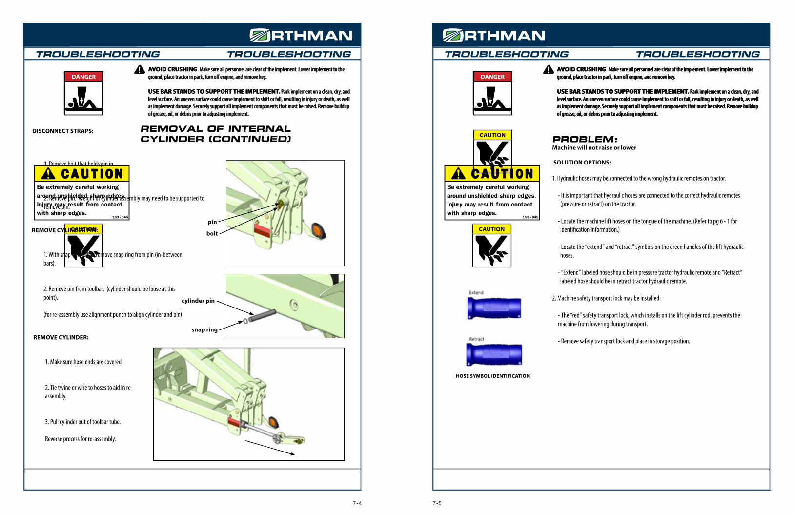
The majority of the 1tRIPr® XD Combo is assembled at Orthman Mfg., Inc. The 1tRIPr XD Combo is assembled in an appropriate shipping configuration to ensure transport safety and efficiency from the manufacturer.
CAUTION
Wing Lock Pin
The 1tRIPr® XD Combo may ship folded or unfolded, depending on configurations. If the toolbar ships unfolded (shown picture above) it will most likely have the rigid wing lock pins installed. These pins will need to be removed prior to folding the toolbar. (see pg. 5 - 1)
The 1tRIPr® XD Combo will also come from the factory without the safety lights or the SMV installed, due to the potential for damage to those items during shipment. These items will also need to be installed prior to use or transport of the 1tRIPr® XD Combo.
CAUTION! BE EXTREMELY CAREFUL WORKING AROUND UNSHIELDED SHARP EDGES. INJURY MAY RESULT FROM CONTACT WITH SHARP EDGES.
Wing Lock Pin
Unfolded Shipping Configuration
Folded Shipping Configuration
3 - 5
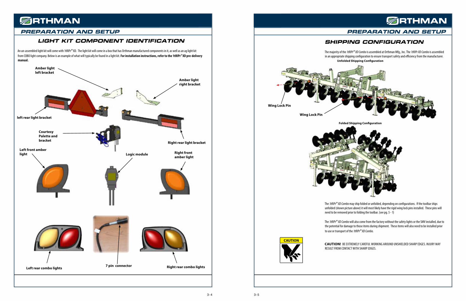
Right rear combo lightsLeft rear combo lights
Logic module
7 pin connector
Right front amber light
LIGHT KIT COMPONENT IDENTIFICATION
An un-assembled light kit will come with 1tRIPr® XD. The light kit will come in a box that has Orthman manufactured components in it, as well as an ag light kit from COBO light company. Below is an example of what will typically be found in a light kit. For installation instructions, refer to the 1tRIPr® XD pre-delivery manual.
Amber lightright bracket
Amber lightleft bracket
Courtesy Palette and bracket
Left front amber light
Right rear light bracket
left rear light bracket
3 - 4

PREPARATION AND SETUP PREPARATION AND SETUP
MACHINE TO TRACTOR CONNECTION (CONTINUED)
DANGER! Escaping pressurized hydraulic fluid can penetrate skin, resulting in injury or death. Relieve hydraulic system pressure before connecting or disconnecting trac-tor. Use cardboard or wood, NOT BODY PARTS, to check for suspected hydraulic leaks. Wear protective gloves and safety glasses or goggles when working with hydraulic systems. If an accident occurs, see a doctor immediately for proper treatment.
CONNECT HYDRAULIC HOSES TO TRACTOR:
1. Four (4) hydraulic hoses are located on the machine tongue. Two (2) hoses possess blue colored handles. Two (2) hoses possess green colored handles. The hoses with blue handles are the wing fold hoses. The hoses with green handles are the machine lift and lower hoses.
2. Each hose also possesses an “extend” symbol or a “retract” symbol. (See illustration) Connect the “extend” labeled hoses to the pressure port of a tractor SCV remote. Connect the “retract” labeled hoses to the retract port of a corresponding tractor SCV remote.
HOSE SYMBOL IDENTIFICATIONMACHINE TONGUE
HOSES
3 - 7
DANGER
PREPARATION AND SETUP
PREPARING THE TOOLBAR
Tooling options available for added 1tRIPr® XD Combo versatility are illustrated and explained in the tooling options section of this manual. Field adjustments are illustrated and explained in the field settings section of this manual.
Tooling options available for the 1tRIPr® row units are illustrated and explained in the tooling options section of the 1tRIPr® row unit operator’s manual.
Be sure to consult the 1tRIPr® row unit operator’s manual before attempting to operate the implement. Read and understand operator manuals for machinery used in conjunction with the 1tRIPr® XD Combo.
Before each use, check hardware for wear and proper torque. Replace damaged or missing hardware with hardware of an identical grade to restore implement to original specifications.
MACHINE TO TRACTOR CONNECTIONAVOID CRUSHING. Do not stand between tractor and implement when connecting or disconnect-ing implement. Injury or death can result from being trapped between the tractor and implement.
AVOID CRUSHING. Make sure all personnel are clear of the implement. Lower implement to the ground, place tractor in park, turn off engine, and remove key.
USE BAR STANDS TO SUPPORT THE IMPLEMENT. Park implement on a clean, dry, and level surface. An uneven surface could cause implement to shift or fall, resulting in injury or death, as well as implement damage. Securely support all implement components that must be raised.
CONNECT TRACTOR DRAWBAR TO XDR TONGUE TAB:
1. Position the rear of the tractor in front of the tongue tab on the XD Combo tongue.
2. Connect machine lift hydraulic hoses to a tractor hydraulic SCV remote to enable the tongue to raise up or lower down to align the XD Combo tongue tab with the tractor drawbar.
3. Move tractor into the position that will enable the hitch pin to be inserted through both the tractor drawbar and XD Combo tongue tab.
4. Place tractor in park.
5. Insert hitch pin
CAUTION! Escaping pressurized hydraulic fluid can penetrate skin, resulting in injury or death. Relieve hydraulic system pressure before connecting or disconnecting trac-tor. Use cardboard or wood, NOT BODY PARTS, to check for suspected hydraulic leaks. Wear protective gloves and safety glasses or goggles when working with hydraulic systems. If an accident occurs, see a doctor immediately for proper treatment.
DANGER
DANGER
CAUTION
OPERATOR’S
MANUAL
3 - 6
DANGER

TOOLING OPTIONS AND INSTALLATIONPREPARATION AND SETUP TOOLING OPTIONS AND INSTALLATION
TONGUE TAB
The 1tRIPr® XD Combo comes standard with a Category 3/Category 4 tongue tab (152-806) with an insert for a 1 1/2” tractor hitch pin size (Cat. 3) and an additional tab insert for a 2” (5.08 cm) tractor hitch pin size (Cat 4), which can replace the Category 3 tab insert by removal of the snap ring above the tab insert and then removing the tab insert from the internal socket. Also available is a Category 5 tongue tab (152-805) with a tab insert for a 2 3/4” (6.99 cm) tractor hitch pin size. These tongue tabs have an internal socket that fits the pin closely. This eliminates implement backlash and improves control.
DANGER
CAUTION
1. Determine level mounting location. see page 5 - 3. Tractor drawbar heights vary.2. Insert Tonge Tab in-between Tongue Tab mountin plates on Tongue.3. Align bolts in correct holes, and fasten using nuts and lockwashers.4. After tightening, tongue tab mount plates should clamp tight on Tongue tab. If gap exists it may be necessary to shim inside with a flat or machined washer.
NOTE: IT IS IMPORTANT THAT THE TONGUE TAB MOUNT PLATES CLAMP TIGHT ON THE TONGUE TAB. RECOMMENDED TOOLS: IMPACT WRENCH, 1 1/2” IMPACT SOCKET, 1 1/2” END WRENCH.
Tongue
for 2” pin
152-806
Tongue Tab
Tongue Tab mount holes
MOUNTING OF TONGUE TABAVOID CRUSHING. Make sure all personnel are clear of the implement. Lower implement to the ground, place tractor in park, turn off engine, and remove key.
USE BAR STANDS TO SUPPORT THE IMPLEMENT. Park implement on a clean, dry, and level surface. An uneven surface could cause implement to shift or fall, resulting in personal injury or death, as well as implement damage. Securely support all implement components that must be raised. Remove buildup of grease, oil, or debris prior to installing row unit mounts.
152-805
for 2 3/4” pin
4 - 1
MACHINE TO SECONDARY IMPLEMENT CONNECTIONAVOID CRUSHING. Do not stand between tractor and implement when connecting or disconnect-ing implement. Injury or death can result from being trapped between the tractor and implement.
AVOID CRUSHING. Make sure all personnel are clear of the implement. Lower implement to the ground, place tractor in park, turn off engine, and remove key.
USE BAR STANDS TO SUPPORT THE IMPLEMENT. Park implement on a clean, dry, and level surface. An uneven surface could cause implement to shift or fall, resulting in injury or death, as well as implement damage. Securely support all implement components that must be raised.
TO CONNECT MACHINE TO SECONDARY IMPLEMENT:
1. The secondary implement should be staged on a level ground surface, free of obstacles.
2. The XD Combo machine should be completely attached to the tractor (i.e. all hydraulic lines hooked up and bar stands in the upright position).
3. All three hitch pins in the secondary implement hitch should be removed.
4. The lower hitch tug arm support pins should be in the desired position above the lower hitch tug arms.
5. Position the XD Combo in front of the secondary implement, and within a distance that allows the XD Combo secondary implement connection arms to be connected to the secondary implement.
6. Lower the XD Combo to the ground surface
7. Place each of the lower secondary implement connecting arms into the secondary implement’s lower hitch brackets. Insert each hitch pin.
8. Connect the top link to the secondary implement’s top link hitch bracket and insert pin.
9. Connect secondary implement hydraulic hoses to the XD Combo secondary implement quick connect couplers at the rear of the machine lift frame.
DANGER
DANGER
3 - 8

TOOLING OPTIONS AND INSTALLATION TOOLING OPTIONS AND INSTALLATION
LIFT TIRE SCRAPER PACKAGE
The lift tire scraper package is an additional component used to control residue build up on the lift tires. Excessive buildup of field residue can adversely affect the operating height of the machine. Each scraper mounts to the lift wheel yolk frame with provided hardware.
MOUNTING BOLTHOLES
MOUNTING BOLTS
SCRAPER PLATE BOLTS
COMBO LIFT WHEELS
INSTALLATION:
AVOID CRUSHING. Make sure all personnel are clear of the implement. Lower implement to the ground, place tractor in park, turn off engine, and remove key.
USE BAR STANDS TO SUPPORT THE IMPLEMENT. Park implement on a clean, dry, and level surface. An uneven surface could cause implement to shift or fall, resulting in personal injury or death, as well as implement damage. Securely support all implement components that must be raised. Remove buildup of grease, oil, or debris prior to installing row unit mounts.
1. Mount tire scraper bracket to lift wheel with mounting bolts, lock washers, and flange nuts (4).
2. Mount tire scraper to scraper bracket with carriage mounting bolts and flange nuts (2).
3. Tighten all hardware to proper torque specifications.
NOTE: WHEN INSTALLING THE TIRE SCRAPER, DO NOT ALLOW TIRE SCRAPER TO COME INTO CONTACT WITH THE TIRE. TIRE TO SCRAPER CONTACT WILL CAUSE PREMATURE TIRE WEAR.
DANGER
4 - 3
LIQUID FERTILIZER TANK PACKAGE
The 1tRIPr® XD Combo can be equipped with dual 500 gallon nutrient application tanks. These tanks rest in a saddle frame which is mounted to the combo lift frame as shown. NOTE: THE XD COMBO FERTILIZER PACKAGE DOES NOT INCLUDE PUMPS, HOSES, AND OTHER WETWARE.
1
2
FERTILIZER TANK PACKAGE IDENTIFICATION:
1. DUAL 500 GALLON TANKS
2. TANK PACKAGE FRAME
3. TANK SADDLE
DANGER
3
INSTALLATION:
AVOID CRUSHING. Make sure all personnel are clear of the implement. Lower implement to the ground, place tractor in park, turn off engine, and remove key.
USE BAR STANDS TO SUPPORT THE IMPLEMENT. Park implement on a clean, dry, and level surface. An uneven surface could cause implement to shift or fall, resulting in personal injury or death, as well as implement damage. Securely support all implement components that must be raised. Remove buildup of grease, oil, or debris prior to installing row unit mounts.
1. The fertilizer tank package frame rests atop the combo lift frame. There are 16 sloted bolt holes for securing the tank frame.
2. Rest the tank frame squarely onto the combo lift frame and secure with provided hardware.
1tRIPr® XD COMBO WITH DUAL FERTILIZER TANKS
4 - 2

FIELD SETTINGSTOOLING OPTIONS AND INSTALLATION
PLACE MACHINE TOOLBAR COMPONENTS IN “FIELD READY” POSITION:
AVOID CRUSHING. Do not stand between tractor and implement when connecting or disconnect-ing implement. Injury or death can result from being trapped between the tractor and implement.
AVOID CRUSHING. Make sure all personnel are clear of the implement. Lower implement to the ground, place tractor in park, turn off engine, and remove key.
USE BAR STANDS TO SUPPORT THE IMPLEMENT. Park implement on a clean, dry, and level surface. An uneven surface could cause implement to shift or fall, resulting in injury or death, as well as implement damage. Securely support all implement components that must be raised.
PLACE TRACTOR IN PARK AND REMOVE KEY BEFORE DISMOUNTING TRACTOR TO ADJUST IMPLEMENT.
NEVER ALLOW RIDERS ON TRACTOR OR IMPLEMENT. Riders hinder operator visibil-ity and can be thrown from the implement and/or be struck by foreign objects resulting in injury or death.
Raise bar stand up
1. Make sure machine is attached securely to tractor drawbar.
2. Make sure cab hydraulic control configuration is easily accessible and to the preference of the primary operator.
3. Make sure tractor is adequately ballasted for safe operation. Refer to owner’s manual for proper ballasting instructions.
4. After tractor hook-up raise the machine and remove Bar stand pin and raise bar stand to raised position, and replace bar stand pin.
5. Move Rigid wing lock pin from Rigid wing lock position to Lock pin storage position. The toolbar will not fold with the Rigid wing lock pins installed in the Rigid lock position.
FIELD OPERATION
W A R N I N G
offW A R N I N G
Bar stand pin
DANGER
DANGER
Lock pin storage position
Rigid wing lock position
Rigid wing lock pin
5 - 1
NURSE TANK HITCH
For situations in which the secondary implement is separated from the 1tRIPr® XD Combo, and only nutrient application and seedbed preparation is needed, an optional nurse tank hitch is available. The 1tRIPr® XD Combo nurse tank hitch attaches to the secondary implement draft links at the rear of the machine.
DANGERINSTALLATION:
AVOID CRUSHING. Make sure all personnel are clear of elevated objects during installation.
1. Remove draft pins in the upper third link and lower draft tugs of the nurse tank hitch.
2. Raise the hitch up to the secondary implement hitch, align the pin slots, and re-insert the pins.
NURSE TANK HITCH MOUNTED
4 - 4

FIELD SETTINGS FIELD SETTINGS
TOOLBAR HEIGHT AND ORIENTATIONPLACE TRACTOR IN PARK AND REMOVE KEY BEFOREDISMOUNTING TRACTOR TO ADJUST IMPLEMENT.
NEVER ALLOW RIDERS ON TRACTOR OR IMPLEMENT. Riders hinder operator visibility and can be thrown from the implement and/or be struck by foreign objects resulting in injury or death.
NOTE: WHEN SETTING TOOLBAR HEIGHT AND ORIENTATION, DISREGARD ROW UNIT PERFORMANCE. TOOLBAR HEIGHT AND ORIENTATION MUST BE ESTABLISHED PRIOR TO TOOLING ADJUSTMENT. FOR 1TRIPR® TOOLING ADJUSTMENT, REFER TO THE 1TRIPR® ROW UNIT OPERATOR’S MANUAL.
The top and bottom of the toolbar must operate parallel with the ground surface. Adjustment of tractor hitch tab height, tongue lift cylinder stops, and/or lifting gauge wheel cylinder stops, will allow the toolbar to operate parallel with the ground surface.
Have an assistant pull the tractor and implement slowly forward in the field position as you view the end of the toolbars from a safe distance. Observe the toolbars heights and orientations while in operation. Make adjustments accordingly until the top and bottom of both toolbars operate parallel with the ground surface .
1tRIPr® XD Combo in raised position
In the rasied position, there should be adequate clearance between the ground surface and the 1tRIPr® shank.
1tRIPr® XD Combo in field position
1. In the field position, the 1tRIPr® XD Combo toolbar should run 30”-32” above the ground surface.
2. Row unit parallel linkage should run parallel with the ground surface and not be resting on the toolbar.
offW A R N I N G
W A R N I N G
5 - 3
30-32”(76-81cm)
Ground Surface
Hitch Tab height
5 - 2
FIELD OPERATION
Rigid wing lock position
Lock pin storage position
Rigid wing lock pin
RIGID OPERATION. For Rigid operation in the field: With wings completely unfolded, move Rigid wing lock pin from Lock pin storage position and install into Rigid wing lock position. This will keep wing from floating up. NOTE: TOOLBAR WILL NOT BE ABLE TO FOLD WITH WINGS LOCKED DOWN.
WING LEVELING. Factory setting for wing level bolts allows no downward wing position from level. If wings become out of adjustment, these bolts can be moved. Wing leveling bolts can also be adjusted so that wings will float down below factory setting. Smaller 1tRIPr® XD Combo machines will have 1 wing level bolt on each wing. Larger 1tRIPr® XD Combo machines will have 2 wing level bolts for each wing (shown below). If there are two wing level bolts per wing it is important that these bolts are adjusted so that both of them make contact with the wing so the load is distributed evenly.
To adjust Wing leveling bolts: 1. Loosen Jam nut. 2. Adjust bolt or bolts. 3. Tighten Jam nut. Recommended Tools: 1 13/16 end wrench.
NOTE: JAM NUTS ARE IMPORTANT FOR PROTECTING THE THREADS IN THE TAPPED PLATE AND SHOULD NOT EVER BE REMOVED FROM THE ASSEMBLY.
Wing leveling bolts making contact on wing plate
Wing leveling bolts Jam nuts

HYDRAULICSNOTES
HYDRAULIC MANIFOLD BLOCK #180-332PORT HOSE ASSIGNMENT FUNCTION
FOLD TRACTOR TO MANIFOLD PRESSURE I SUPPLIES OIL TO MANIFOLD TO EXTEND WING FOLD CYLINDERS
UNFOLD TRACTOR TO MANIFOLD RETRACT I SUPPLIES OIL TO MANIFOLD TO RETRACT WING FOLD CYLINDERS
LAWP TRACTOR TO MANIFOLD PRESSURE II SUPPLIES OIL TO MANIFOLD TO LIFT MACHINE
LAWR TRACTOR TO MANIFOLD RETRACT II SUPPLIES OIL TO MANIFOLD TO LOWER MACHINE
LP1MANIFOLD TO LEFT WING FOLD
CYLINDER1 (BASE END)SUPPLIES OIL TO LEFT WING FOLD CYLINDER 1 DURING FOLDING
LP2*MANIFOLD TO LEFT WING FOLD CYLINDER
2 (BASE END)SUPPLIES OIL TO LEFT WING FOLD CYLINDER 2 DURING FOLDING
LR1MANIFOLD TO LEFT WING FOLD CYLINDER
1 (ROD END)SUPPLIES OIL TO LEFT WING FOLD CYLINDER 1 DURING UNFOLDING
LR2*MANIFOLD TO LEFT WING FOLD CYLINDER
2 (ROD END)SUPPLIES OIL TO LEFT WING FOLD CYLINDER 2 DURING UNFOLDING
RP1MANIFOLD TO RIGHT WING FOLD CYLIN-
DER 1 (BASE END)SUPPLIES OIL TO RIGHT WING FOLD CYLINDER 1 DURING FOLDING
RP2*MANIFOLD TO RIGHT WING FOLD CYLIN-
DER 2 (BASE END)SUPPLIES OIL TO RIGHT WING FOLD CYLINDER 2 DURING FOLDING
RR1MANIFOLD TO RIGHT WING FOLD CYLIN-
DER 1 (ROD END)SUPPLIES OIL TO RIGHT WING FOLD CYLINDER 1 DURING UNFOLDING
RR2*MANIFOLD TO RIGHT WING FOLD CYLIN-
DER 2 (ROD END)SUPPLIES OIL TO RIGHT WING FOLD CYLINDER 2 DURING UNFOLDING
TPTONGUE CYLINDER TO MANIFOLD (BASE
END)SUPPLIES OIL TO TONGUE CYLINDER DURING MACHINE LIFTING
TRTONGUE CYLINDER TO MANIFOLD (ROD
END)SUPPLIES OIL TO TONGUE CYLINDER DURING MACHINE LOWERING
P3 MANIFOLD TO COMBO LIFT FLOW DIVIDER SUPPLIES OIL TO COMBO LIFT WHEELS DURING MACHINE LIFTING
R3 MANIFOLD TO COMBO LIFT MANIFOLD SUPPLIES OIL TO COMBO LIFT WHEELS DURING MACHINE LOWERING
P4 NOT USED PORT SHOULD BE PLUGGED
R4 NOT USED PORT SHOULD BE PLUGGED
MAIN HYDRAULIC MANIFOLD BLOCK PORT IDENTIFICATION
The 1tRIPr® XD Combo is equipped with a hydraulic manifold block located near the top link center mast plates, which directs oil to multiple cylinders that must perform together to accomplish a specific function. The hydraulic manifold block may be unique to the configuration of your machine. Refer to the parts section of this manual to determine which hydraulic manifold block is equipped on your machine. Below is a port identification chart of the hydraulic manifold block.
*NOTE: PORT IS NOT USED ON TOOLBARS WITH ONLY 2 WING FOLD CYLINDERS (12R30 and smaller configurations)
6 - 15 - 4

HYDRAULICS HYDRAULICS
MACHINE FOLD HYDRAULIC HOSE ROUTING
HOSES ENTER TOOLBAR NEAR MANIFOLD
2 CYLINDER FOLDING TOOLBARS(12R30 AND SMALLER CONFIGURATIONS)
4 CYLINDER FOLDING TOOLBARS(12R36 AND LARGER CONFIGURATIONS)
HOSES ENTER TOOLBAR NEAR MANIFOLD
HOSES ENTER TOOLBAR NEAR MANIFOLD
INTERNAL CYLINDER INTERNAL CYLINDER
For individual hose identification, refer to the Hydraulic Manifold Block Port Identifcation and Toolbar Hydraulic Hose parts identification .
For individual hose identification, refer to the Hydraulic Manifold Block Port Identifcation and Toolbar Hydraulic Hose parts identification .
6 - 3
PORT IDENTIFICATION NOTES PORT IDENTIFICATION NOTES
A* Aux. Lift Wheel Retract Rod end of lift wheel cylinder J Lift Wheel Pressure Base end of LH lift wheel cylinders
B Auxiliary Retract Ports Ports are normally plugged K Auxiliary Ports Ports normally plugged
C* Aux. Lift Wheel Pressure Base end of lift wheel cylinder L Lift Wheel Pressure Base end of RH lift wheel cylinders
D Lift Wheel Pressure inlet 1 Routes to flow divider port P M* Aux. Lift Wheel Retract Rod end of lift wheel cylinder
E Lift Wheel Pressure inlet 2 Routes to flow divider port Q N* Aux. Lift Wheel Pressure Base end of lift wheel cylinder
F Main Retract Port Routes to main manifold block port R3 O Main Pressure Port Routes to main manifold block port P3
G Lift Wheel Retract Rod end of LH lift wheel cylinders P Flow Divider Pressure 1 Routes to manifold port E
H Auxiliary Ports Ports normally plugged Q Flow Divider Pressure 2 Routes to manifold port D
I Lift Wheel Retract Rod end of RH lift wheel cylinders - --- ----
COMBO LIFT HYDRAULIC MANIFOLD BLOCK AND FLOW DIVIDER PORT IDENTIFICATION
O
B
F
D
A
C
E Q
P
J
G
K
H
L
I
N
M
HYDRAULIC MANIFOLD BLOCK AND FLOW DIVIDER(FRONT VIEW)
HYDRAULIC MANIFOLD BLOCK AND FLOW DIVIDER
(REAR VIEW)
* Ports only used on 6 wheel configurations. Ports plugged on 4 wheel configurations.
6 - 2

TROUBLESHOOTINGAVOID CRUSHING. Make sure all personnel are clear of the implement. Lower implement to the ground, place tractor in park, turn off engine, and remove key.
USE BAR STANDS TO SUPPORT THE IMPLEMENT. Park implement on a clean, dry, and level surface. An uneven surface could cause implement to shift or fall, resulting in injury or death, as well as implement damage. Securely support all implement components that must be raised. Remove buildup of grease, oil, or debris prior to adjusting implement.
DANGER
CAUTION
C A U T I O NBe extremely careful working around unshielded sharp edges. Injury may result from contact with sharp edges.
153 - 045
153-045.indd 1 1/12/2005 8:49:28 AM
HYDRAULICS TROUBLESHOOTINGAVOID CRUSHING. Make sure all personnel are clear of the implement. Lower implement to the ground, place tractor in park, turn off engine, and remove key.
USE BAR STANDS TO SUPPORT THE IMPLEMENT. Park implement on a clean, dry, and level surface. An uneven surface could cause implement to shift or fall, resulting in injury or death, as well as implement damage. Securely support all implement components that must be raised. Remove buildup of grease, oil, or debris prior to adjusting implement.
DANGER
7 - 1
DANGER
CAUTION PROBLEM:Wings do not fold or unfold.
SOLUTION OPTIONS:
1. Rigid wing lock pins installed. • Remove wing lock pins.
2. Hydraulic tips installed incorrectly in tractor SCV. • Refer to to tractor operator’s manual or dealer for tractor hydraulic specifications.
3. Tractor hydraulic pressure is insuffficient. • Refer to tractor operator’s manual or dealer for tractor hydraulic specifications.
NOTE: TO AVOID FOREIGN OBJECTS IN HYDRAULIC OIL, ALWAYS CLEAN HYDRAULIC TIPS AND OUTLETS. FOREIGN MATERIAL CAN RUIN CYLINDERS AND PLUG RESTRICTORS.
MACHINE LIFTHYDRAULIC HOSE ROUING
HOSES ROUTE TO LIFT CYLINDERS
HOSES ROUTE FROM FLOW DIVIDER TO MACHINE LIFT
MANIFOLDHOSE ROUTES TO MAIN TOOLBAR
MANIFOLD BLOCK(RETRACT)
HOSE ROUTES TO MAIN TOOLBAR MANIFOLD BLOCK
(PRESSURE)
MACHINE LIFT MANIFOLD/ FLOW DIVIDER
HOSE ROUTING FROM MAIN MANIFOLD BLOCK TO TONGUE CYLINDER
6 - 4

TROUBLESHOOTING TROUBLESHOOTINGAVOID CRUSHING. Make sure all personnel are clear of the implement. Lower implement to the ground, place tractor in park, turn off engine, and remove key.
USE BAR STANDS TO SUPPORT THE IMPLEMENT. Park implement on a clean, dry, and level surface. An uneven surface could cause implement to shift or fall, resulting in injury or death, as well as implement damage. Securely support all implement components that must be raised. Remove buildup of grease, oil, or debris prior to adjusting implement.
DANGER
CAUTION
AVOID CRUSHING. Make sure all personnel are clear of the implement. Lower implement to the ground, place tractor in park, turn off engine, and remove key.
USE BAR STANDS TO SUPPORT THE IMPLEMENT. Park implement on a clean, dry, and level surface. An uneven surface could cause implement to shift or fall, resulting in injury or death, as well as implement damage. Securely support all implement components that must be raised. Remove buildup of grease, oil, or debris prior to adjusting implement.
DANGER
CAUTION
C A U T I O NBe extremely careful working around unshielded sharp edges. Injury may result from contact with sharp edges.
153 - 045
153-045.indd 1 1/12/2005 8:49:28 AM
C A U T I O NBe extremely careful working around unshielded sharp edges. Injury may result from contact with sharp edges.
153 - 045
153-045.indd 1 1/12/2005 8:49:28 AM
TROUBLESHOOTINGAVOID CRUSHING. Make sure all personnel are clear of the implement. Lower implement to the ground, place tractor in park, turn off engine, and remove key.
USE BAR STANDS TO SUPPORT THE IMPLEMENT. Park implement on a clean, dry, and level surface. An uneven surface could cause implement to shift or fall, resulting in injury or death, as well as implement damage. Securely support all implement components that must be raised. Remove buildup of grease, oil, or debris prior to adjusting implement.
DANGER
7 - 3
DANGERDANGER
CAUTIONREMOVAL OF INTERNAL CYLINDER
FOLD TOOLBAR:
1. Be sure rigid locking pin is in storage position.
2. Fold wings over until they hit wing stops so weight of wings are on stops.
DISCONNECT HYDRAULIC HOSES:
1. Relive hydraulic system pressure in tractor.
2. Unhook hydraulic hoses and store in courtsey palette.
3. Locate cylinder hoses on the hydraulic manifold and disconnect. The wing hoses will be located on the sides of the hydraulic manifold block.
Hydraulic manifold
Wing hoses
TROUBLESHOOTINGAVOID CRUSHING. Make sure all personnel are clear of the implement. Lower implement to the ground, place tractor in park, turn off engine, and remove key.
USE BAR STANDS TO SUPPORT THE IMPLEMENT. Park implement on a clean, dry, and level surface. An uneven surface could cause implement to shift or fall, resulting in injury or death, as well as implement damage. Securely support all implement components that must be raised. Remove buildup of grease, oil, or debris prior to adjusting implement.
DANGER
7 - 2
DANGERDANGER
CAUTIONPROBLEM:Wings do not fold or unfold. (cont.)
SOLUTION OPTIONS:
4. Hydraulic flow divider is faulty or plugged. • Refer to (pg. 9 - 9) for hydraulic manifold breakdown. • Flow divider may need to be removed and cleaned or possibly replaced.
5. Hydraulic cylinder restrictors could be plugged. • Refer to (pg. 7 - 3 & 7 - 4) for removall process of cylinder assembly. 1. Remove hose from cylinder. 2. Remove adaptor that goes in-between hose and cylinder port. 3. Restrictor is located inside the adaptor and can be removed with allen wrench. 4. Restrictor is made from a set screw with a .055 hole drilled in it. 5. Check to see if hole is plugged. 6. Clean and re-install. • Refer to (pg. 9 - 10) for cylinder component identification and replacement parts.
6. Cylinder seal kit is bad.
• Refer to (pg. 7 - 3 & 7 - 4) for removal process of cylinder assembly. • Refer to (pg. 9 - 21) for cylinder internal component identification and seal kit part
number.
NOTE: TO AVOID FOREIGN OBJECTS IN HYDRAULIC OIL, ALWAYS CLEAN HYDRAULIC TIPS AND OUTLETS. FOREIGN MATERIAL CAN RUIN CYLINDERS AND PLUG RESTRICTORS.
TROUBLESHOOTING TROUBLESHOOTINGAVOID CRUSHING. Make sure all personnel are clear of the implement. Lower implement to the ground, place tractor in park, turn off engine, and remove key.
USE BAR STANDS TO SUPPORT THE IMPLEMENT. Park implement on a clean, dry, and level surface. An uneven surface could cause implement to shift or fall, resulting in injury or death, as well as implement damage. Securely support all implement components that must be raised. Remove buildup of grease, oil, or debris prior to adjusting implement.
DANGER
CAUTION
AVOID CRUSHING. Make sure all personnel are clear of the implement. Lower implement to the ground, place tractor in park, turn off engine, and remove key.
USE BAR STANDS TO SUPPORT THE IMPLEMENT. Park implement on a clean, dry, and level surface. An uneven surface could cause implement to shift or fall, resulting in injury or death, as well as implement damage. Securely support all implement components that must be raised. Remove buildup of grease, oil, or debris prior to adjusting implement.
DANGER
CAUTION
C A U T I O NBe extremely careful working around unshielded sharp edges. Injury may result from contact with sharp edges.
153 - 045
153-045.indd 1 1/12/2005 8:49:28 AM
C A U T I O NBe extremely careful working around unshielded sharp edges. Injury may result from contact with sharp edges.
153 - 045
153-045.indd 1 1/12/2005 8:49:28 AM
TROUBLESHOOTINGAVOID CRUSHING. Make sure all personnel are clear of the implement. Lower implement to the ground, place tractor in park, turn off engine, and remove key.
USE BAR STANDS TO SUPPORT THE IMPLEMENT. Park implement on a clean, dry, and level surface. An uneven surface could cause implement to shift or fall, resulting in injury or death, as well as implement damage. Securely support all implement components that must be raised. Remove buildup of grease, oil, or debris prior to adjusting implement.
DANGER
7 - 5
AVOID CRUSHING. Make sure all personnel are clear of the implement. Lower implement to the ground, place tractor in park, turn off engine, and remove key.
USE BAR STANDS TO SUPPORT THE IMPLEMENT. Park implement on a clean, dry, and level surface. An uneven surface could cause implement to shift or fall, resulting in injury or death, as well as implement damage. Securely support all implement components that must be raised. Remove buildup of grease, oil, or debris prior to adjusting implement.
DANGER
CAUTION PROBLEM:Machine will not raise or lower
SOLUTION OPTIONS:
1. Hydraulic hoses may be connected to the wrong hydraulic remotes on tractor.
- It is important that hydraulic hoses are connected to the correct hydraulic remotes (pressure or retract) on the tractor.
- Locate the machine lift hoses on the tongue of the machine. (Refer to pg 6 - 1 for identification information.)
- Locate the “extend” and “retract” symbols on the green handles of the lift hydraulic hoses.
- “Extend” labeled hose should be in pressure tractor hydraulic remote and “Retract” labeled hose should be in retract tractor hydraulic remote.
2. Machine safety transport lock may be installed.
- The “red” safety transport lock, which installs on the lift cylinder rod, prevents the machine from lowering during transport.
- Remove safety transport lock and place in storage position.
HOSE SYMBOL IDENTIFICATION
TROUBLESHOOTINGAVOID CRUSHING. Make sure all personnel are clear of the implement. Lower implement to the ground, place tractor in park, turn off engine, and remove key.
USE BAR STANDS TO SUPPORT THE IMPLEMENT. Park implement on a clean, dry, and level surface. An uneven surface could cause implement to shift or fall, resulting in injury or death, as well as implement damage. Securely support all implement components that must be raised. Remove buildup of grease, oil, or debris prior to adjusting implement.
DANGERDANGER
REMOVAL OF INTERNAL CYLINDER (CONTINUED)
DISCONNECT STRAPS:
1. Remove bolt that holds pin in.
2. Remove pin. Weight of cylinder assembly may need to be supported to remove pin.
bolt
pinREMOVE CYLINDER PIN:
1. With snap-ring pliers remove snap ring from pin (in-between bars).
2. Remove pin from toolbar. (cylinder should be loose at this point).
(for re-assembly use alignment punch to align cylinder and pin)
cylinder pin
snap ringREMOVE CYLINDER:
1. Make sure hose ends are covered.
2. Tie twine or wire to hoses to aid in re-assembly.
3. Pull cylinder out of toolbar tube.
Reverse process for re-assembly.
7 - 4

MAINTENANCENOTES
PRACTICE SAFE MAINTENANCE
Proper maintenance is your responsibility. Maintenance neglect and/or poor maintenance practices can result in injury or death. Always use the proper tools to maintain implement.
AVOID CRUSHING. Make sure all personnel are clear of the implement.Lower implement to the ground, place tractor in park, turn off engine, and remove key.
USE BAR STANDS AND CYLINDER STOPS TO SUPPORT THE IMPLEMENT. Park implement on a clean, dry, and level surface. An uneven surface could cause implement to shift or fall, resulting in injury or death, as well as implement damage. Securely support all implement components that must be raised. Remove buildup of grease, oil, or debris prior to maintaining implement.
AVOID ENTANGLEMENT. Never lubricate or service implement in motion. Keep away from power driven parts when in motion. Disengage power sources prior to maintain-ing implement. Injury or death can result from contact with power driven parts when in motion.
AVOID CRUSHING. Do not stand between the tractor and implement when connect-ing or disconnecting implement. Injury or death can result from being trapped between the tractor and implement.
Escaping pressurized hydraulic fluid can penetrate skin, resulting in injury or death. Relieve hydraulic system pressure before connecting or disconnecting tractor. Use cardboard or wood, NOT BODY PARTS, to check for suspected hydraulic leaks. Wear protective gloves and safety glasses or goggles when working with hydraulic systems. If an accident occurs, see a doctor immediately for proper treatment.
DANGER
DANGER
DANGER
DANGER
WARNING
off
8 - 17 - 6

MAINTENANCE MAINTENANCE
LUBRICATION
• Grease - use high quality multi-purpose grease. • Follow recommended hourly service intervals illustrated below.
GREASE
10
Tongue Hitch Tab
30
Tongue Lift Cylinder pins
30XD Combo Tongue to
1tRIPr Toolbar bushings
8 - 3
TORQUE SPECIFICATIONSUnified Inch Bolt and Screw Torque Values
Bolt or Screw
Size
SAE Grade 1 SAE Grade 2a SAE Grade 5, 5.1 or 5.2 SAE Grade 8 or 8.2
Lubricatedb Dryc Lubricatedb Dryc Lubricatedb Dryc Lubricatedb Dryc
N•m lb-in N•m lb-in N•m lb-in N•m lb-in N•m lb-in N•m lb-in N•m lb-in N•m lb-in
1/4 3.7 33 4.7 42 6 53 7.5 66 9.5 84 12 106 13.5 120 17 150
N•m lb-ft N•m lb-ft
5/16 7.7 68 9.8 86 12 106 15.5 137 19.5 172 25 221 28 20.5 35 26
N•m lb-ft N•m lb-ft
3/8 13.5 120 17.5 155 22 194 27 240 35 26 44 32.5 49 36 63 46
N•m lb-ft N•m lb-ft N•m lb-ft
7/16 22 194 28 20.5 35 26 44 32.5 56 41 70 52 80 59 100 74
N•m lb-ft
1/2 34 25 42 31 53 39 67 49 85 63 110 80 120 88 155 115
9/16 48 35.5 60 45 76 56 95 70 125 92 155 115 175 130 220 165
5/8 67 49 85 63 105 77 135 100 170 125 215 160 240 175 308 225
3/4 120 88 150 110 190 140 240 175 300 220 380 280 425 315 540 400
7/8 190 140 240 175 190 140 240 175 490 360 615 455 690 510 870 640
1 285 210 360 265 285 210 360 265 730 540 920 680 1030 760 1300 960
1-1/8 400 300 510 375 400 300 510 375 910 670 1150 850 1450 1075 1850 1350
1-1/4 570 420 725 535 570 420 725 535 1280 945 1630 1200 2050 1500 2600 1920
1-3/8 750 550 950 700 750 550 950 700 1700 1250 2140 1580 2700 2000 3400 2500
1-1/2 990 730 1250 930 990 730 1250 930 2250 1650 2850 2100 3600 2650 4550 3350
Torque values listed are for general use only, based on the strength of the bolt or screw. DO NOT use these values if a different torque value or tightening procedure is given for a specific application. For plastic insert or crimped steel type lock nuts, for stainless steel fasteners, or for nuts on U-bolts, see the tightening instructions for the specific application. Shear bolts are designed to fail under predetermined loads. Always replace shear bolts with identical grade.
Replace fasteners with the same or higher grade. If higher grade fasteners are used, tighten these to the strength of the original. Make sure fastener threads are clean and that you properly start thread engagement. When possible, lubricate plain or zinc plated fasteners other than lock nuts, wheel bolts or wheel nuts, unless different instructions are given for the specific application.
a Grade 2 applies for hex cap screws (not hex bolts) up to 6. in (152 mm) long. Grade 1 applies for hex cap screws over 6 in. (152 mm) long, and for all other types of bolts and screws of any length.b “Lubricated” means coated with a lubricant such as engine oil, fasteners with phosphate and oil coatings, or 7/8 in. and larger fasteners with JDM F13C zinc flake coating.
c “Dry” means plain or zinc plated without any lubrication, or 1/4 to 3/4 in. fasteners with JDM F13B zinc flake coating.
8 - 2

MAINTENANCE MAINTENANCE
50Wing Hinge bushings2 zerks on each wing
LUBRICATION
• Grease - use high quality multi-purpose grease. • Follow recommended 50 hour service interval illustrated below.
GREASE
50
IMPLEMENT INSPECTION• When replacement parts are necessary for periodic maintenance and servicing, genuine
factory replacement parts must be used to restore implement to original specifications. Replace broken or worn parts immediately. Contact your Orthman dealer for replacement parts.
• During break-in (40 hours), check hardware for proper torque every 10 to 20 hours. (pg. 8 - 2)
• Before each use, check hardware for wear and proper torque. (pg. 8 - 2) Replace damaged or missing hardware with hardware of an identical grade to restore implement to original specifications.
• Do not allow debris to buildup on any surface of the implement.
• Replace all shields and guards. Be sure all tools, parts, and service equipment are removed prior to transporting equipment.
8 - 5
LUBRICATION
• Grease - use high quality multi-purpose grease. • Follow recommended hourly service interval illustrated below.
GREASE
50Internal fold
DUAL CYLINDER TOOLBAR
30Lifting Wheel Cylinder pins
8 - 4

PARTS IDENTIFICATIONMAINTENANCE
9 - 1
Parts list located on the following page.
16
18
17
7
14
11
6
1
30
15
35
4
6
8
10
3733
283
220
11
5
9
31
16
14
13
19
12
17
38
27
32 34
2933 32
36
39
21
26
2423
25
22
TONGUE ASSEMBLYIMPLEMENT STORAGE
• Clean and touch up paint seasonally to avoid corrosion and rust. Contact your Orthman dealer for touch up paint.
• Inspect all safety and Orthman decals and replace if missing or damaged. Contact your Orthman dealer for replacement decals.
• Grease all zerks regardless of hourly interval prior to storage.
• Check all hardware according to torque specifications prior to storage.
• Replace all worn or damaged parts prior to storage.
• Store inside if possible. Storing implement inside will prolong the life of the components.
AVOID CRUSHING. Make sure all personnel are clear of the implement. Lower implement to the ground, place tractor in park, turn off engine, and remove key.
Storing implement on the ground will relieve the tractor three point hitch of hydraulic pres-sure.Hydraulic systems tend to settle, endangering anything underneath the implement.
USE BAR STANDS TO SUPPORT THE IMPLEMENT. Store implement on a clean, dry, and level surface. An uneven surface could cause implement to shift or fall, resulting in injury or death, as well as implement damage. Securely support all implement components that must be raised. Store implement away from human activity.
AVOID CRUSHING. Never use the tongue bar stand to support the weight of the machine. Tongue bar stand may fail if machine weight rests on the tongue bar stand. Only use the tongue bar stand to keep the tongue from resting on the ground.
DANGER
WARNING
off
8 - 6

PARTS IDENTIFICATIONPARTS IDENTIFICATION
A
9
10
6
8
7
5
3
4
1
6
12
14
13
15
11
11
15
2
TOOLBAR HINGE ASSEMBLY 7X7 FRONT BARKey Part # Description Qty Notes Key Part # Description Qty Notes
1 342-810 Hinge pin 2 2” x 22” long 9 100-471 Bolt 4 1 1/4” x 3”, Grade 8
2 100-206 Bolt 2 3/4” x 1 1/2”, Grade 5 10 102-077 Jam nut 4 1 1/4”
3 108-022 Lock washer 2 3/4” 11 134-040 Bushing, split 8 1 7/8” x 1 1/2” x 3/4” long
4 108-011 Flat washer 2 3/4” 12 134-097 Bushing, split 4 2 1/2” x 2” x 1 1/2” long
5 342-809 Lock pin 2 1” x 22 7/16” long 13 134-094 Bushing, split 4 2 1/2” x 2” x 3” long
6 104-065 Linch pin 4 5/16” x 1 11/16” 14 341-651 Spacer 4 2 3/8” long
7 303-846 Barstand pin 2 3/4” x 5” long 15 110-001 Grease fitting 8 1/4” straight
8 303-744 Bar stand 2 48”
9 - 39 - 2
TONGUE ASSEMBLYKey Part # Description Qty Notes Key Part # Description Qty Notes
1 348-196 Tongue Frame 1 --- 21 196-373 Hydraulic Hose 4 1/2” - tractor to mani.
2 348-184 Tongue Module 2 --- 22 198-326 Union 4 3/4MJ x 3/4MJ
3 348-183 Module Clamp 2 --- 23 152-299 Hose Holder 1
4 100-156 Bolt 6 3/4” x 2”, Grade 5 24 100-115 Bolt 1 1/2” x 1 1/4”, Grade 5
5 100-158 Bolt 6 3/4” x 2 1/2”, Grade 5 25 108-020 Lock washer 1 1/2”
6 102-105 Flange nut 12 3/4”, serrated 26 108-001 Flat washer 1 1/2” SAE
7 100-124 Bolt 2 1/2” x 3 1/4”, Grade 5 27 352-067 Tongue Stand 1
8 102-028 Lock nut 2 1/2” 28 153-044 Decal 1 Important
9 348-205 Pin 2 --- 29 153-528 Decal 1 Warning - Hyd. pressure
10 348-198 Safety Stop 1 --- 30 153-167 Decal 1 Danger - Pinch
11 104-251 Safety snap pin 1 3/8” x 4” x 4 3/4” 31 100-569 Bolt 2 1” x 3 1/2”, Grade 5
12 194-464 Cylinder 1 6” x 6” welded 32 108-025 Lock washer 4 1”
13 348-179 Pin 1 --- 33 102-214 Lock nut 4 1” Nylock
14 100-305 Flange bolt 2 1/2” x 1”, Grade 8 34 130-037 Safety Chain 2 CAT4
15 348-197 Pin 1 --- 35 100-405 Bolt 2 1” x 7 1/2”, Grade 8
16 100-306 Bolt 2 1/2” x 2 3/4”, Grade 8 36 348-811 Hydraulic storage 1 package (see pg. x-x)
17 102-224 Lock nut 2 1/2”37
152-806Hitch Tab 1
CAT4 ( 2” tractor pin )
18 505-379 Collar 2 --- 152-805 CAT5 ( 2 3/4” tractor pin )
19 198-246 Elbow 2 7/8MB x 3/4MJ 90 degrees 38 505-854 Pin and cotter key 1
20 196-352 Hydraulic Hose 4 1/2” x 132” - bulkhead to mani. 39 153-627 Decal 1 Danger

PARTS IDENTIFICATIONPARTS IDENTIFICATION
9 - 5
1
23
4 5
6
7
8
MACHINE LIFT ASSEMBLYKey Part # Description Qty Notes
1 100-195 Bolt 24 1” x 3 1/4”
2 108-025 Lock washer 24 1”
3 102-111 Hex nut 24 1”
4 344-203 Hose caddy 1 Used for holding quick connect hoses for the secondary implement
5 100-105 Bolt 2 3/8” x 3/4”
6 108-018 Lock washer 2 3/8”
7 344-014 Hydraulic manifold kit 1 For individual parts breakdown, see pg. (XX)
8 344-610 Machine lift wheel assembly 4 For individual parts breakdown, see pg. (XX)
9 344-625 Extra lift wheel package 1 6 wheel lift machines only; For individual parts breakdown, see pg. (xx)
9
9 - 4
8
7
6
9
2
1
3
5
4
4
TOOLBAR CENTER SECTION ASSEMBLYKey Part # Description Qty Notes
1 303-744 Bar stand 2 ----
2 303-846 Pin 2 ----
3 104-065 Lynch pin 2 ----
4 134-097 Bushing 4 ----
5 110-002 Grease fitting 2 ----
6 152-588 Wing rest bumper 2 ----
7 108-003 Flat washer 2 3/4”
8 100-075 Bolt 2 3/4” x 2 1/2”
9 352-075 Edge guard 2 Cut to length

PARTS IDENTIFICATIONPARTS IDENTIFICATION
9 - 7
2
2
1
3
2
2
WHEEL HUB ASSEMBLYKey Part # Description Qty Notes
1 344-104 Spacer 1 ----
2 120-058 Bearing 4 ----
3 100-555 Wheel stud 8 5/8” x 2.5
9 - 6
1
35
9 6
13
12
11
14
15
15 1416
1713
13
24
7
10
8
LIFT WHEEL ASSEMBLYKey Part # Description Qty Notes Key Part # Description Qty Notes
1 100-206 Bolt 1 3/4” x 1 1/2” 10 190-056 Tire and Rim 1 385/65R22.5
2 102-117 Nut 1 1 1/2” 11 194-428 Hydraulic Cylinder 1 ----
3 108-022 Lock washer 1 3/4” 12 366-114 Pin 1 ----
4 108-063 Lock washer 1 1 1/2” 13 100-305 Bolt 3 1/2” x 1”
5 342-214 Pin retainer 1 --- 14 301-793 Pin collar 2 ----
6 344-094 Pin 1 --- 15 104-008 Roll pin 2 ----
7 344-102 Wheel hub 1 Breakdown on pg. xx 16 198-080 Elbow fitting 2 7/8”-14MB - 9/16”-18MJ
8 344-105 Bolt 1 Wheel bolt 17 344-623 Pin 1 ----
9 344-611 Wheel Fork 1 ----

PARTS IDENTIFICATIONPARTS IDENTIFICATION
HYDRAULIC MANIFOLD ASSEMBLY Key Part # Description Qty Notes
1 180-332 Manifold block 1 no fittings, used on all machines except for 12R30, 8R30, and narrow transport configurations
2 198-078 Adaptor 6 3/4 - 16MB - 9/16-18MJ
3 198-210 Plug 1 3/4 - 16MB
4 198-089 Elbow 6 3/4 - 16MB - 3/4 - 16MJ
5 100-215 Bolt 2 3/8 - 16 x 5 1/2 GR. 5
6 198-128 Adaptor 4 3/4-16MB - 3/4MJ
7 180-279 Flow Divider 1 -----
8 108-018 Lock Washer 2 3/8
9 102-005 Nut 2 3/8-16 GR. 2
10 198-064 Elbow 2 3/4-16MB - 9/16-18MJ
381-332 Manifold pkg. Includes items 1-10
381-334 Manifold pkg. 12R30 configuration only; Includes items 1-10, but with 2 less elbows and 2 more adaptors,
2
1
3
2
2
4
44
4
4
45 2
10
10
2
2
6
6
6
6
7
9
8
5
9 - 9
7
9
9
11
143
10
11
6
5
8
12
2
MACHINE LIFT HYDRAULIC MANIFOLD/GEAR FLOW DIVIDER ASSEMBLY
Key Part # Description Qty Notes Key Part # Description Qty Notes
1 100-114 Bolt 2 1/2” x 1” 7 198-078 Adaptor fitting 8 3/4”-16MB - 9/16”-18MJ
2 106-148 Screw 2 3/8” x 3” 8 198-128 Adaptor fitting 1 3/4”-16MB - 3/4”MJ
3 108-001 Flat washer 2 1/2” 9 198-210 Plug 10 3/4”-16MB
4 108-020 Lock washer 2 1/2” 10 198-289 Adaptor fitting 1 1 5/16”-12MB x 3/4”-16MJ
5 180-288 Manifold 1 no fittings 11 198-301 Elbow fitting 2 3/4”-16MJ - 3/4”FJX
6 180-289 Gear flow divider 1 no fittings 12 198-246 Elbow fitting 2 7/8”-14MB - 3/4”-16MJ
9 - 8

PARTS IDENTIFICATIONPARTS IDENTIFICATION
2
1
3
4
5
6
7
MACHINE LIFT HYDRAULIC MANIFOLD
OUTER LEFT LIFT WHEEL
INNER LEFT LIFT WHEEL
INNER RIGHT LIFT WHEEL
OUTER RIGHT LIFT WHEEL
8
Key Part # Description Qty Notes
1 196-232 Hydraulic hose 1 3/8” x 72” ; End fittings - 9/16FJX x 9/16FJX
2 196-233 Hydraulic hose 1 3/8” x 66” ; End fittings - 9/16FJX x 9/16FJX
3 196-235 Hydraulic hose 1 3/8” x 34” ; End fittings - 9/16FJX x 9/16FJX
4 196-234 Hydraulic hose 1 3/8” x 42” ; End fittings - 9/16FJX x 9/16FJX
5 196-231 Hydraulic hose 1 3/8” x 52” ; End fittings - 9/16FJX x 9/16FJX
6 302-851 Hydraulic hose 1 3/8” x 44” ; End fittings - 9/16FJX x 9/16FJX
7 196-054 Hydraulic hose 1 3/8” x 76” ; End fittings - 9/16FJX x 9/16FJX
8 196-230 Hydraulic hose 1 3/8” x 82” ; End fittings - 9/16FJX x 9/16FJX
9 196-179 Hydraulic hose 2 1/2” x 30” ; End fittings - 3/4FJX x 3/4MB
9 9
HYDRAULIC HOSE IDENTIFICATION(4 WHEEL MACHINE LIFT)
9 - 11
4 12
6
1413
19
1
8
7 15
22
1211
20
20
18
3
8
8
3
10
5
16
5
17
2124
24
21
22
23
INTERNAL FOLD ASSEMBLYKey Part # Description Qty Notes Key Part # Description Qty Notes
1 100-115 Bolt 1 1/2” x 1 1/4”, Grade 5 14 301-512 Friction plate 2 ---
2 100-125 Bolt 2 1/2” x 4 1/4”, Grade 5 15 301-548 Linkage pin 1 ---
3 102-007 Nut 2 1/2”16
301-500 Pin 1 6 7/8” long (for 3/8” wall bars)
4 104-052 Snap ring 2 1 1/2” external 301-800 Pin 1 6 9/16” long (for 1/2” wall bars)
5 104-053 Snap ring 2 1” external17
301-948 Pin 1 5 7/8” long (for 3/8” wall bars)
6 106-107 Screw 4 3/8” x 3/4” 301-945 Pin 1 5 5/8” long (for 1/2” wall bars)
7 108-001 Flat washer 1 1/2” 18 341-823 Connecting strap 2 ---
8 108-020 Lock washer 3 1/2”19
301-511 Guide wheel 2 3/4” thick (for 3/8” wall bars)
9 301-802 Guide wheel 2 5/8” thick (for 1/2” wall bars)
10 194-499 Cylinder 1 4” x 24” 20 317-714 Spacer 2 ---
11 134-040 Bushing, split 2 1 7/8” x 1 1/2” x 3/4” 21 340-078 Adaptor 2 9/16” MB x 9/16 MJ
12 134-041 Machined washer 4 2 1/4” x 1 1/2” x 14 ga. 22 100-098 Bolt 1 3/8” x 3”, Grade 5
13134-040 Bushing, split 2 1 7/8” x 1 1/2” x 3/4” 23 102-027 Lock nut 1 3/8”
134-047 Bushing, split 2 1 3/4” x 1 1/2” x 5/8” 24 340-057 Restrictor 2 3/8” x 3/8” with .055 hole
9 - 10

PARTS IDENTIFICATIONPARTS IDENTIFICATION
TOOLBAR MANIFOLD
BLOCK
B
AB
A
B
AB
A
RH WING FOLD CYLINDERS LH WING FOLD CYLINDERS
HYDRAULIC HOSE IDENTIFICATION(WING FOLD)
Parts list located on the following page.
9 - 13
OUTER LEFT LIFT WHEEL
INNER LEFT LIFT WHEEL
EXTRALIFT WHEEL
INNER RIGHT LIFT WHEEL
OUTER RIGHT LIFT WHEEL
EXTRALIFT WHEEL
2
1
3
4
5
6
7
8
9 9
MACHINE LIFT HYDRAULIC MANIFOLD
11
10
13
12
HYDRAULIC HOSE IDENTIFICATION(6 WHEEL MACHINE LIFT)
Key Part # Description Qty Notes
1 196-232 Hydraulic hose 1 3/8” x 72” ; End fittings - 9/16FJX x 9/16FJX
2 196-233 Hydraulic hose 1 3/8” x 66” ; End fittings - 9/16FJX x 9/16FJX
3 196-235 Hydraulic hose 1 3/8” x 34” ; End fittings - 9/16FJX x 9/16FJX
4 196-234 Hydraulic hose 1 3/8” x 42” ; End fittings - 9/16FJX x 9/16FJX
5 196-231 Hydraulic hose 1 3/8” x 52” ; End fittings - 9/16FJX x 9/16FJX
6 302-851 Hydraulic hose 1 3/8” x 44” ; End fittings - 9/16FJX x 9/16FJX
7 196-054 Hydraulic hose 1 3/8” x 76” ; End fittings - 9/16FJX x 9/16FJX
8 196-230 Hydraulic hose 1 3/8” x 82” ; End fittings - 9/16FJX x 9/16FJX
9 196-179 Hydraulic hose 2 1/2” x 30” ; End fittings - 3/4FJX x 3/4MB
10 196-240 Hydraulic hose 1 3/8” x 100” ; End fittings - 9/16FJX x 9/16FJX
11 196-241 Hydraulic hose 1 3/8” x 106” ; End fittings - 9/16FJX x 9/16FJX
12 196-404 Hydraulic hose 1 3/8” x 110” ; End fittings - 9/16FJX x 9/16FJX
13 196-242 Hydraulic hose 1 3/8” x 116” ; End fittings - 9/16FJX x 9/16FJX
9 - 12
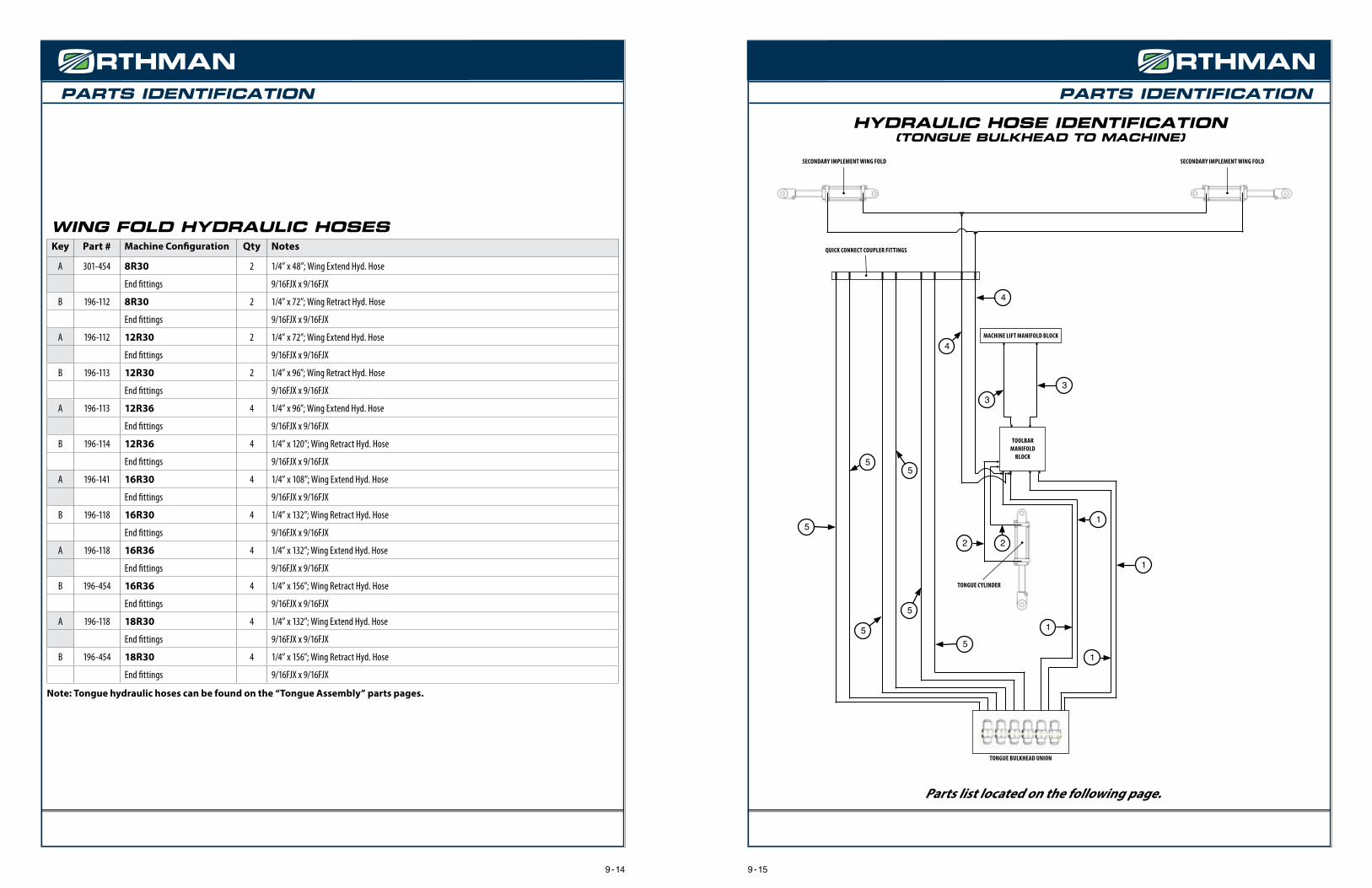
PARTS IDENTIFICATIONPARTS IDENTIFICATION
TOOLBAR MANIFOLD
BLOCK
MACHINE LIFT MANIFOLD BLOCK
SECONDARY IMPLEMENT WING FOLD SECONDARY IMPLEMENT WING FOLD
TONGUE CYLINDER
TONGUE BULKHEAD UNION
QUICK CONNECT COUPLER FITTINGS
1
1
1
1
22
5
5
5
5
5
5
3
3
4
4
HYDRAULIC HOSE IDENTIFICATION(TONGUE BULKHEAD TO MACHINE)
Parts list located on the following page.
9 - 15
WING FOLD HYDRAULIC HOSES Key Part # Machine Configuration Qty Notes
A 301-454 8R30 2 1/4” x 48”; Wing Extend Hyd. Hose
End fittings 9/16FJX x 9/16FJX
B 196-112 8R30 2 1/4” x 72”; Wing Retract Hyd. Hose
End fittings 9/16FJX x 9/16FJX
A 196-112 12R30 2 1/4” x 72”; Wing Extend Hyd. Hose
End fittings 9/16FJX x 9/16FJX
B 196-113 12R30 2 1/4” x 96”; Wing Retract Hyd. Hose
End fittings 9/16FJX x 9/16FJX
A 196-113 12R36 4 1/4” x 96”; Wing Extend Hyd. Hose
End fittings 9/16FJX x 9/16FJX
B 196-114 12R36 4 1/4” x 120”; Wing Retract Hyd. Hose
End fittings 9/16FJX x 9/16FJX
A 196-141 16R30 4 1/4” x 108”; Wing Extend Hyd. Hose
End fittings 9/16FJX x 9/16FJX
B 196-118 16R30 4 1/4” x 132”; Wing Retract Hyd. Hose
End fittings 9/16FJX x 9/16FJX
A 196-118 16R36 4 1/4” x 132”; Wing Extend Hyd. Hose
End fittings 9/16FJX x 9/16FJX
B 196-454 16R36 4 1/4” x 156”; Wing Retract Hyd. Hose
End fittings 9/16FJX x 9/16FJX
A 196-118 18R30 4 1/4” x 132”; Wing Extend Hyd. Hose
End fittings 9/16FJX x 9/16FJX
B 196-454 18R30 4 1/4” x 156”; Wing Retract Hyd. Hose
End fittings 9/16FJX x 9/16FJX
Note: Tongue hydraulic hoses can be found on the “Tongue Assembly” parts pages.
9 - 14

PARTS IDENTIFICATIONPARTS IDENTIFICATION
1
3
2
6 5 7
12
9
8
11
13 4
3
14
10
SECONDARY IMPLEMENT HITCH ASSEMBLYKey Part # Description Qty Notes Key Part # Description Qty Notes
1 102-009 Hex nut 20 3/4” 8 344-028 Pin 2 ----
2 100-159 Bolt 20 3/4” x 2 3/4” 9 104-102 Roll pin 4 ----
3 108-022 Lock washer 22 3/4” 10 348-085 LIft frame tail 1 ----
4 100-155 Bolt 2 3/4” x 1 3/4” 11 348-080 Tug arm 2 ----
5 108-001 Flat washer 2 1/2” 12 344-038 Pin 2 ----
6 100-115 Bolt 2 1/2” x 1 1/4” 13 342-214 Pin retainer 2 ----
7 108-020 Lock washer 2 1/2” 14 152-683 Top link 1 ----
9 - 17
TONGUE BULKHEAD TO MACHINE HOSESKey Part # Description Qty Notes
1 196-352 Machine lift hydraulic hoses - Bulkhead to Toolbar Manifold Block 4 1/2” x 132” ; End fittings - 3/4FJX x 3/4FJX
2 196-561 Tongue Cylinder hydraulic hose - Toolbar Manifold Block tongue cylinder 2 1/2” x 27” ; End fittings - 3/4FJX x 3/4MB
3 196-344 Machine lift hydraulic hoses - Toolbar Manifold Block to Machine Lift Manifold Block 2 1/2” x 192” ; End fittings - 3/4FJX x 3/4FJX
4 196-318 Secondary Implement wing fold hoses - Toolbar Manifold Block to Quick Connect 2 1/2” x 180” ; End fittings - 3/4FJX x 3/4MB
5 196-036 Secondary Implement auxiliary hoses 6 1/2” x 216” ; End fittings 3/4FJX x 3/4FJX
9 - 16

PARTS IDENTIFICATIONPARTS IDENTIFICATION
2
11
4
10
1
47
8
3
56
9
12
LIGHT BRACKET ASSEMBLY Key Part # Description Qty Notes Key Part # Description Qty Notes
1 341-772 Light Bracket 1 Front LH 7 153-109 SMV sign 1 ----
2 341-774 Light Bracket 1 Front RH 8 102-077 Screw 2 1/4” x 3/4”
3 348-524 Light Bracket 1 Rear LH 9 102-085 Nut 2 1/4
4 348-528 Light Bracket 1 Rear RH 10 100-157 Bolt 4 3/4”-10 x 2 1/4” GR.5
5 100-001 Bolt 4 Carriage; 1/4”-20 X 1” 11 108-022 Lock Washer 4 3/4”
6 102-227 Nut 4 1/4”-20 12 102-009 Nut 4 3/4”
303-915 Light Bracket pkg. Includes items 1-12
9 - 19
42
3
1
5
ADDITIONAL LIFT WHEELS ASSEMBLY (6 WHEEL CONFIGURATIONS ONLY)
Key Part # Description Qty Notes
1 100-155 Bolt 20 3/4” x 1 3/4”
2 102-009 Hex nut 20 3/4”
3 108-022 Lock washer 20 3/4”
4 344-626 RH lift wheel frame 1 ----
5 344-627 LH lift wheel frame 1 ----
9 - 18

PARTS IDENTIFICATIONPARTS IDENTIFICATION
HYDRAULIC CYLINDER INTERNAL (WING FOLD)Key Part # Description Qty Notes
1 194-440 Seal kit 1 for 194-499 cylinder
2 194-406 Cylinder rod 1 ---
3 194-288 Gland 1 ---
4 194-293 Piston 1 ---
2
3
1
4
9 - 219 - 20
LIGHT KIT ASSEMBLYKey Part # Description Qty Notes
152-850 XD Light Kit -- Includes all parts in above. Cobo brand
Call the Orthman parts department for individual replacement lights.

NOTES NOTES
9 - 239 - 22

NOTES
9 - 24