1pipelining (i) - safari research group
TRANSCRIPT
Design of Digital Circuits (252-0028-00L), Spring 2020
Optional HW 4: Pipelining, Tomasulo’s Algorithm,and Out-of-Order Execution
SOLUTIONS
Instructor: Prof. Onur MutluTAs: Mohammed Alser, Rahul Bera, Can Firtina, Juan Gomez-Luna, Jawad Haj-Yahya, Hasan Hassan,
Konstantinos Kanellopoulos, Lois Orosa, Jisung Park, Geraldo De Oliveira Junior, Minesh Patel, Giray Yaglikci
Released: Wednesday, April 15, 2020
1 Pipelining (I)
Given the following code:
1 MUL R3, R1, R22 ADD R5, R4, R33 ADD R6, R4, R14 MUL R7, R8, R95 ADD R4, R3, R76 MUL R10 , R5, R6
Calculate the number of cycles it takes to execute the given code on the following models:Note 1: Each instruction is specified with the destination register first.Note 2: Do not forget to list any assumptions you make about the pipeline structure (e.g., how is data
forwarding done between pipeline stages)Note 3: For all machine models, use the basic instruction cycle as follows:
• Fetch (one clock cycle)• Decode (one clock cycle)• Execute (MUL takes 6, ADD takes 4 clock cycles). The multiplier and the adder are not pipelined.• Write-back (one clock cycle)
(a) A non-pipelined machine
MUL: 1 + 1 + 6 + 1 = 9 cyclesADD: 1 + 1 + 4 + 1 = 7 cycles
9 + 7 + 7 + 9 + 7 + 9 = 48 cycles
1/20

(b) A pipelined machine with scoreboarding and five adders and five multipliers without data forwarding
28 cycles
PC Cycles 1 2 3 4 5 6 7 8 9 10 11 12 13 14 15 161 MUL R3, R1, R2 F D E E E E E E W2 ADD R5, R4, R3 F D - - - - - - - E E E E W3 ADD R6, R4, R1 F - - - - - - - D E E E E W4 MUL R7, R8, R9 F D E E E E5 ADD R4, R3, R7 F D - - -6 MUL R10, R5, R6 F - - -PC Cycles ... 15 16 17 18 19 20 21 22 23 24 25 26 27 281 MUL R3, R1, R2 ...2 ADD R5, R4, R3 ... W3 ADD R6, R4, R1 ... E W4 MUL R7, R8, R9 ... E E E E W5 ADD R4, R3, R7 ... - - - - - - E E E E W6 MUL R10, R5, R6 ... - - - - - - D E E E E E E W
(c) A pipelined machine with scoreboarding and five adders and five multipliers with data forwarding.
26 cycles
PC Cycles 1 2 3 4 5 6 7 8 9 10 11 12 13 14 15 161 MUL R3, R1, R2 F D E E E E E E W2 ADD R5, R4, R3 F D - - - - - - E E E E W3 ADD R6, R4, R1 F - - - - - - D E E E E W4 MUL R7, R8, R9 F D E E E E E5 ADD R4, R3, R7 F D - - - -6 MUL R10, R5, R6 F - - - -PC Cycles ... 15 16 17 18 19 20 21 22 23 24 25 26 27 281 MUL R3, R1, R2 ...2 ADD R5, R4, R3 ...3 ADD R6, R4, R1 ... W4 MUL R7, R8, R9 ... E E E W5 ADD R4, R3, R7 ... - - - - E E E E W6 MUL R10, R5, R6 ... - - - - D E E E E E E W
2/20
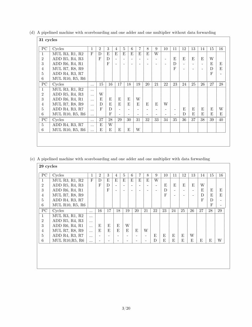
(d) A pipelined machine with scoreboarding and one adder and one multiplier without data forwarding
31 cycles
PC Cycles 1 2 3 4 5 6 7 8 9 10 11 12 13 14 15 161 MUL R3, R1, R2 F D E E E E E E W2 ADD R5, R4, R3 F D - - - - - - - E E E E W3 ADD R6, R4, R1 F - - - - - - - D - - - E E4 MUL R7, R8, R9 F - - - D E5 ADD R4, R3, R7 F -6 MUL R10, R5, R6PC Cycles ... 15 16 17 18 19 20 21 22 23 24 25 26 27 281 MUL R3, R1, R2 ...2 ADD R5, R4, R3 ... W3 ADD R6, R4, R1 ... E E E E W4 MUL R7, R8, R9 ... D E E E E E E W5 ADD R4, R3, R7 ... F D - - - - - - - E E E E W6 MUL R10, R5, R6 ... F - - - - - - - D E E E EPC Cycles ... 27 28 29 30 31 32 33 34 35 36 37 38 39 405 ADD R4, R3, R7 ... E W6 MUL R10, R5, R6 ... E E E E W
(e) A pipelined machine with scoreboarding and one adder and one multiplier with data forwarding
29 cycles
PC Cycles 1 2 3 4 5 6 7 8 9 10 11 12 13 14 15 161 MUL R3, R1, R2 F D E E E E E E W2 ADD R5, R4, R3 F D - - - - - - E E E E W3 ADD R6, R4, R1 F - - - - - - D - - - E E E4 MUL R7, R8, R9 F - - - D E E5 ADD R4, R3, R7 F D -6 MUL R10, R5, R6 F -PC Cycles ... 16 17 18 19 20 21 22 23 24 25 26 27 28 291 MUL R3, R1, R2 ...2 ADD R5, R4, R3 ...3 ADD R6, R4, R1 ... E E E W4 MUL R7, R8, R9 ... E E E E E W5 ADD R4, R3, R7 ... - - - - - - E E E E W6 MUL R10,R5, R6 ... - - - - - - D E E E E E E W
3/20
2 Pipelining (II)
Consider two pipelined machines implementing MIPS ISA, Machine I and Machine II:Both machines have the following five pipeline stages, very similarly to the basic 5-stage pipelined MIPS
processor we discussed in lectures, and one ALU :
1. Fetch (one clock cycle)
2. Decode (one clock cycle)
3. Execute (one clock cycle)
4. Memory (one clock cycle)
5. Write-back (one clock cycle).
Machine I does not implement interlocking in hardware. It assumes all instructions are independent andrelies on the compiler to order instructions such that there is sufficient distance between dependentinstructions. The compiler either moves other independent instructions between two dependent instruc-tions, if it can find such instructions, or otherwise, inserts nops. Assume internal register file forwarding(an instruction writes into a register in the first half of a cycle and another instruction can correctlyaccess the same register in the next half of the cycle). Assume that the processor predicts all branchesas always-taken.
Machine II implements data forwarding in hardware. On detection of a flow dependence, it forwards anoperand from the memory stage or from the write-back stage to the execute stage. The load instruction(lw) can only be forwarded from the write-back stage because data becomes available in the memorystage but not in the execute stage like for the other instructions. Assume internal register file forwarding(an instruction writes into a register in the first half of a cycle and another instruction can access thesame register in the next half of the cycle). The compiler does not reorder instructions. Assume that theprocessor predicts all branches as always-taken.Consider the following code segment:
Copy: lw $2, 100($5)sw $2, 200($6)addi $1, $1, 1bne $1, $25, Copy
Initially, $5 = 0, $6 = 0, $1 = 0, and $25 = 25.
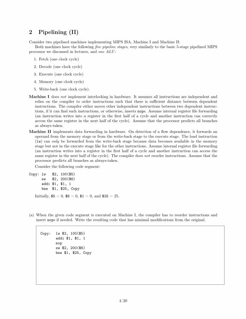
(a) When the given code segment is executed on Machine I, the compiler has to reorder instructions andinsert nops if needed. Write the resulting code that has minimal modifications from the original.
Copy: lw $2, 100($5)addi $1, $1, 1nopsw $2, 200($6)bne $1, $25, Copy
4/20

(b) When the given code segment is executed on Machine II, dependencies between instructions are resolvedin hardware. Explain when data is forwarded and which instructions are stalled and when they arestalled.
In every iteration, data are forwarded for sw and for bne. The instruction sw is dependent on lw, so it isstalled one cycle in every iteration
(c) Calculate the machine code size of the code segments executed on Machine I (part (a)) and Machine II(part (b)).
Machine I - 20 bytes (because of the additional nop)Machine II - 16 bytes
(d) Calculate the number of cycles it takes to execute the code segment on Machine I and Machine II.
Machine I: The compiler reorders instructions and places one nop. This is the execution timeline of thefirst iteration:1 2 3 4 5 6 7 8 9F D E M W
F D E M WN N N N N
F D E M WF D E M W
9 cycles for one iteration. As there are 5 instructions in each iteration and 25 iterations, the total numberof cycles is 129 cycles.
Machine II: The machine stalls sw one cycle in the decode stage. This is the execution timeline of thefirst iteration:1 2 3 4 5 6 7 8 9F D E M W
F D D E M WF F D E M W
F D E M W9 cycles for one iteration. As there are 4 instructions in each iteration and 25 iterations, and one stallcycle in each iteration, the total number of cycles is 129 cycles.
5/20

(e) Which machine is faster for this code segment? Explain.
For this code segment, both machines take the same number of cycles. We cannot say which one is faster,since we do not know the clock frequency.
6/20

3 Pipeline (Reverse Engineering)
The following piece of code runs on a pipelined microprocessor as shown in the table (F: Fetch, D: Decode, E:Execute, M: Memory, W:Write back). Instructions are in the form “Instruction Destination,Source1,Source2.”For example, “ADD A, B, C” means A ← B + C.
Cycles 1 2 3 4 5 6 7 8 9 10 11 12 13 14 15 16 17 180 MUL R5, R6, R7 F D E1 E2 E3 E4 M W1 ADD R4, R6, R7 F D E1 E2 E3 - M W2 ADD R5, R5, R6 F D - - E1 E2 E3 M W3 MUL R4, R7, R7 F - - D E1 E2 E3 E4 M W4 ADD R6, R7, R5 F D - E1 E2 E3 M W5 ADD R3, R0, R6 F - D - - E1 E2 E3 M W6 ADD R7, R1, R4 F - - D E1 E2 E3 M W
Use this information to reverse engineer the architecture of this microprocessor to answer the followingquestions. Answer the questions as precise as possible with the provided information. If the providedinformation is not sufficient to answer a question, answer “Unknown” and explain your reasoning clearly.
(a) How many cycles does it take for an adder and for a multiplier to calculate a result?
3 cycles for adder (E1, E2, E3) and 4 cycles for multiplier (E1, E2, E3, E4).
(b) What is the minimum number of register file read/write ports that this architecture implements? Ex-plain.
The register file has two read ports and one write port.Decode and Writeback stages can be performed simultaneously as seen at cycle 8. Decode reads from tworegisters, Writeback writes to one register.
(c) Can we reduce the execution time of this code by enabling more read/write ports in the register file?Explain.
It is not possible to reduce stall cycles of the given code by only enabling more register file ports, as thepipeline would be stalled due to other limited resources.
(d) Does this architecture implement any data forwarding? If so, how is data forwarding done betweenpipeline stages? Explain.
There is data forwarding from the M stage to E1, as we observe that the instruction 2 starts using R5 atthe clk cycle 7, which is one clk cycle after the instruction 0 finishes calculating its result in the executionunit.Similarly, as another proof of this data forwarding, we observe that the instruction 4 starts using R5 at theclk cycle 10, which is one clk cycle after the instruction 2 finishes calculating its result in the execution unit.
Any other data forwarding is unknown with the given information.
7/20

(e) Is it possible to run this code faster by adding more data forwarding paths? If it is, how? Explain.
Not possible.
All instructions that stall due to data dependency are already using the best possible data forwarding.There is no stall cycles that can be eliminated by enabling another form of data forwarding.
(f) Is there internal forwarding in the register file? If there is not, how would the execution time of the sameprogram change by enabling internal forwarding in the register file? Explain.
The register file already implements internal forwarding, as instruction 6 can finish the decode stage byfetching the value of R4 from the register file in the same cycle that R4 is written (cycle 13).
8/20

(g) Optimize the assembly code in order to reduce the number of stall cycles. You are allowed to reorder, add,or remove ADD and MUL instructions. You are expected to achieve the minimum possible executiontime. Make sure that the register values that the optimized code generates at the end of its executionare identical to the register values that the original code generates at the end of its execution. Justifyeach individual change you make. Show the execution timeline of each instruction and what stage it isin the table below. (Notice that the table below consists of two parts: the first ten cycles at the top, andthe next ten cycles at the bottom.)
• Instruction 1 is useless due to write-after-write, remove it.
• Instruction 3 stalls for decode logic, move it up.
• Instruction 6 does not have read-after-write dependency and can be executed before instr.5. However, it cannot execute before instruction 4 as it would change the value of R7.
New total execution time is 17 cycles instead of 18.
Instr. Instructions Cycles
No 1 2 3 4 5 6 7 8 9 10
0 MUL R5, R6, R7 F D E1 E2 E3 E4 M W
3 MUL R4, R7, R7 F D E1 E2 E3 E4 M W
2 ADD R5, R5, R6 F D - - E1 E2 E3 M
4 ADD R6, R7, R5 F - - D - - E1
6 ADD R7, R1, R4 F - - D
5 ADD R3, R0, R6 F
11 12 13 14 15 16 17 18 19 20
0 MUL R5, R6, R7
3 MUL R4, R7, R7
2 ADD R5, R5, R6 W
4 ADD R6, R7, R5 E2 E3 M W
6 ADD R7, R1, R4 E1 E2 E3 M W
5 ADD R3, R0, R6 D - E1 E2 E3 M W
9/20

4 Tomasulo’s Algorithm (I)
Remember that Tomasulo’s algorithm requires tag broadcast and comparison to enable wake-up of dependentinstructions. In this question, we will calculate the number of tag comparators and size of tag storage requiredto implement Tomasulo’s algorithm in a machine that has the following properties:• 8 functional units where each functional unit has a dedicated separate tag and data broadcast bus• 32 64-bit architectural registers• 16 reservation station entries per functional unit• Each reservation station entry can have two source registers
Answer the following questions. Show your work for credit.
(a) What is the number of tag comparators per reservation station entry?
8 ∗ 2
(b) What is the total number of tag comparators in the entire machine?
16 ∗ 8 ∗ 2 ∗ 8 + 8 ∗ 32
(c) What is the (minimum possible) size of the tag?
log(16 ∗ 8) = 7
(d) What is the (minimum possible) size of the register alias table (or, frontend register file) in bits?
72 ∗ 32 (64 bits for data, 7 bits for the tag, 1 valid bit)
(e) What is the total (minimum possible) size of the tag storage in the entire machine in bits?
7 ∗ 32 + 7 ∗ 16 ∗ 8 ∗ 2
10/20
5 Tomasulo’s Algorithm (II)
In this problem, we consider an in-order fetch, out-of-order dispatch, and out-of-order retirement executionengine that employs Tomasulo’s algorithm. This engine behaves as follows:
• The engine has four main pipeline stages: Fetch (F), Decode (D), Execute (E), and Write-back (W).
• The engine can fetch FW instructions per cycle, decode DW instructions per cycle, and write backthe result of RW instructions per cycle.
• The engine has two execution units: 1) an integer ALU for executing integer instructions (i.e., additionand multiplication) and 2) a memory unit for executing load/store instructions.
• Each execution unit has an R-entry reservation station.
• An instruction always allocates the first available entry of the reservation station (in top-to-bottomorder) of the corresponding execution unit.
The reservation stations are all initally empty. The processor fetches and executes six instructions.Table 1 shows the six instructions and their execution diagram.
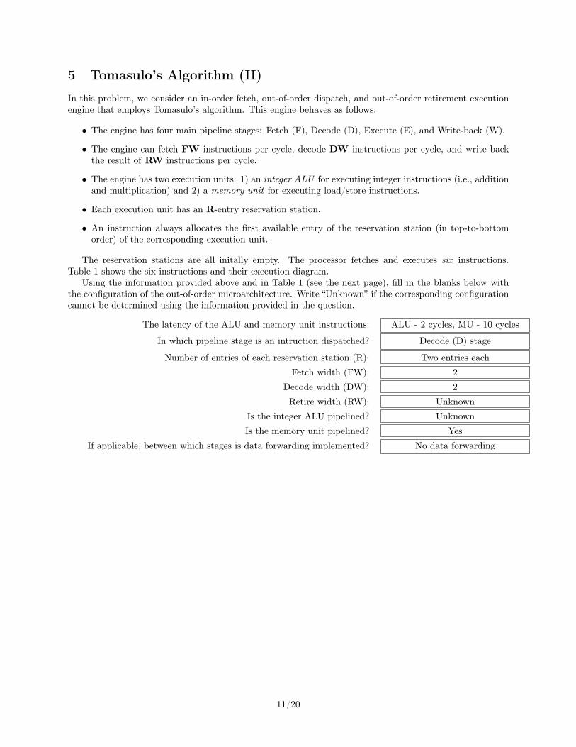
Using the information provided above and in Table 1 (see the next page), fill in the blanks below withthe configuration of the out-of-order microarchitecture. Write “Unknown” if the corresponding configurationcannot be determined using the information provided in the question.
The latency of the ALU and memory unit instructions: ALU - 2 cycles, MU - 10 cycles
In which pipeline stage is an intruction dispatched? Decode (D) stage
Number of entries of each reservation station (R): Two entries eachFetch width (FW): 2
Decode width (DW): 2Retire width (RW): Unknown
Is the integer ALU pipelined? UnknownIs the memory unit pipelined? Yes
If applicable, between which stages is data forwarding implemented? No data forwarding
11/20

Instruction/
Cycle:
12
34
56
78
910
1112
1314
1516
1718
1920
2122
2324
2526
2728
2930
3132
33
1:ADD
R1←
R0,
R1
FD
E1
E2
W
2:LD
R2←
[R1]
FD
--
-E1
E2
E3
E4
E5
E6
E7
E8
E9
E10
W
3:ADDIR1←
R1,
#4
FD
--
E1
E2
W
4:LD
R3←
[R1]
FD
--
--
-E1
E2
E3
E4
E5
E6
E7
E8
E9
E10
W
5:MULR4←
R2,
R3
F-
-D
--
--
--
--
--
--
-E1
E2
W
6:ST
[R0]←
R4
F-
--
--
--
--
--
--
D-
--
--
E1
E2
E3
E4
E5
E6
E7
E8
E9
E10
W
Tab
le1:
Execution
diagram
ofthesixinstructions.
12/20

6 Tomasulo’s Algorithm (Reverse Engineering)
In this problem, we will give you the state of the Register Alias Table (RAT) and Reservation Stations (RS)for an out-of-order execution engine that employs Tomasulo’s algorithm, as we discussed in lectures. Yourjob is to determine the original sequence of four instructions in program order.
The out-of-order machine in this problem behaves as follows:• The frontend of the machine has a one-cycle fetch stage and a one-cycle decode stage. The machine canfetch one instruction per cycle, and can decode one instruction per cycle.• The machine executes only register-type instructions, e.g., OP Rdest ← Rsrc1, Rsrc2.• The machine dispatches one instruction per cycle into the reservation stations, in program order. Dispatchoccurs during the decode stage.• An instruction always allocates the first reservation station that is available (in top-to-bottom order) atthe required functional unit.• When an instruction in a reservation station finishes executing, the reservation station is cleared.• The adder and multiplier are not pipelined. An add operation takes 2 cycles. A multiply operationtakes 3 cycles.• The result of an addition and multiplication is broadcast to the reservation station entries and the RATin the writeback stage. A dependent instruction can begin execution in the next cycle after the writebackif it has all of its operands available in the reservation station entry.• When multiple instructions are ready to execute at a functional unit at the same cycle, the oldest readyinstruction is chosen to be executed first.Initially, the machine is empty. Four instructions then are fetched, decoded, and dispatched into reser-
vation stations. Pictured below is the state of the machine when the final instruction has been dispatchedinto a reservation station:
Reg V Tag Value
RAT
R0
R1
R2
R3
R4
R5
0
0
0
1
A
E
B
5
8–––
–
–––
––
ID
+
V Tag Value V Tag Value
A 0 D – 1 8B 0 A – 0 A –
–
C – – – –– –
ID
×
V Tag Value V Tag Value
D 1 – 5 1 – 5
E 0 A 0 B– –F – – – –– –
13/20

(a) Give the four instructions that have been dispatched into the machine, in program order. The sourceregisters for the first instruction can be specified in either order. Give instructions in the followingformat: “opcode destination ⇐ source1, source2.”
MUL R1 ⇐ R1 , R1
ADD R1 ⇐ R1 , R2
ADD R4 ⇐ R1 , R1
MUL R3 ⇐ R1 , R4
(b) Now assume that the machine flushes all instructions out of the pipeline and restarts fetch from the firstinstruction in the sequence above. Show the full pipeline timing diagram below for the sequence of fourinstructions that you determined above, from the fetch of the first instruction to the writeback of thelast instruction. Assume that the machine stops fetching instructions after the fourth instruction.
As we saw in lectures, use “F” for fetch, “D” for decode, “En” to signify the nth cycle of execution for aninstruction, and “W” to signify writeback. You may or may not need all columns shown.
Cycle: 1 2 3 4 5 6 7 8 9 10 11 12 13 14 15 16MUL R1 ← R1, R1 F D E1 E2 E3 WADD R1 ← R1, R2 F D E1 E2 WADD R4 ← R1, R1 F D E1 E2 WMUL R3 ← R1, R4 F D E1 E2 E3 W
(c) Finally, show the state of the RAT and reservation stations at the end of the 12th cycle of executionin the figure below. Complete all blank parts.
Reg V Tag Value
RAT
R0
R1
R2
R3
R4
R5
1
0
1
1
E
33
8––66
–
–––
–––
–
ID
+
V Tag Value V Tag Value
A
B
C – – – –– –
– – – –– –– – – –– –
ID
×
V Tag Value V Tag Value
D – – E 1 133 66F – – – ––
– – ––
–– –
14/20
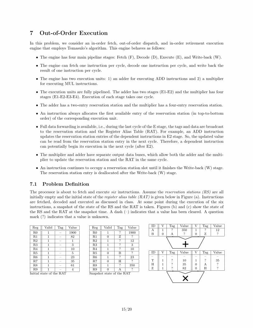
7 Out-of-Order Execution
In this problem, we consider an in-order fetch, out-of-order dispatch, and in-order retirement executionengine that employs Tomasulo’s algorithm. This engine behaves as follows:
• The engine has four main pipeline stages: Fetch (F), Decode (D), Execute (E), and Write-back (W).
• The engine can fetch one instruction per cycle, decode one instruction per cycle, and write back theresult of one instruction per cycle.
• The engine has two execution units: 1) an adder for executing ADD instructions and 2) a multiplierfor executing MUL instructions.
• The execution units are fully pipelined. The adder has two stages (E1-E2) and the multiplier has fourstages (E1-E2-E3-E4). Execution of each stage takes one cycle.
• The adder has a two-entry reservation station and the multiplier has a four-entry reservation station.
• An instruction always allocates the first available entry of the reservation station (in top-to-bottomorder) of the corresponding execution unit.
• Full data forwarding is available, i.e., during the last cycle of the E stage, the tags and data are broadcastto the reservation station and the Register Alias Table (RAT). For example, an ADD instructionupdates the reservation station entries of the dependent instructions in E2 stage. So, the updated valuecan be read from the reservation station entry in the next cycle. Therefore, a dependent instructioncan potentially begin its execution in the next cycle (after E2).
• The multiplier and adder have separate output data buses, which allow both the adder and the multi-plier to update the reservation station and the RAT in the same cycle.
• An instruction continues to occupy a reservation station slot until it finishes the Write-back (W) stage.The reservation station entry is deallocated after the Write-back (W) stage.
7.1 Problem DefinitionThe processor is about to fetch and execute six instructions. Assume the reservation stations (RS) are allinitially empty and the initial state of the register alias table (RAT) is given below in Figure (a). Instructionsare fetched, decoded and executed as discussed in class. At some point during the execution of the sixinstructions, a snapshot of the state of the RS and the RAT is taken. Figures (b) and (c) show the state ofthe RS and the RAT at the snapshot time. A dash (–) indicates that a value has been cleared. A questionmark (?) indicates that a value is unknown.
Reg Valid Tag ValueR0 1 – 1900R1 1 – 82R2 1 – 1R3 1 – 3R4 1 – 10R5 1 – 5R6 1 – 23R7 1 – 35R8 1 – 61R9 1 – 4
Initial state of the RAT
Reg Valid Tag ValueR0 1 ? 1900R1 0 Z ?R2 1 ? 12R3 1 ? 3R4 1 ? 10R5 0 B ?R6 1 ? 23R7 0 H ?R8 1 ? 350R9 0 A ?
Snapshot state of the RAT
ID V Tag Value V Tag ValueA 1 ? 350 1 ? 12B 0 A ? 0 Z ?
ID
+
V Tag Value V Tag Value
D 0 T – 0 H – K 0 D – 0 Z –
ID
×
V Tag Value V Tag Value
H 1 – 35 1 – 35
Z 1 – 82 0 – H
E 1 – 7 1 – 35
T 1 – 14 1 – 35
ID V Tag Value V Tag Value– – – – – – –T 1 ? 10 1 ? 35H 1 ? 35 0 A ?Z 1 ? 82 0 H ?
ID
+
V Tag Value V Tag Value
D 0 T – 0 H – K 0 D – 0 Z –
ID
×
V Tag Value V Tag Value
H 1 – 35 1 – 35
Z 1 – 82 0 – H
E 1 – 7 1 – 35
T 1 – 14 1 – 35
15/20

7.2 (a) Data Flow GraphBased on the information provided above, identify the instructions and complete the dataflow graph below forthe six instructions that have been fetched. Please appropriately connect the nodes using edges and specifythe direction of each edge. Label each edge with the destination architectural register and the correspondingTag. Note that you may not need to use all registers and/or nodes provided below.
7.3 (b) Program InstructionsFill in the blanks below with the six-instruction sequence in program order. When referring to registers,please use their architectural names (R0 through R9). Place the register with the smaller architectural nameon the left source register box. For example, ADD R8 ⇐ R1, R5.
MUL R2 ← R3 , R9
MUL R8 ← R4 , R7
ADD R9 ← R2 , R8
MUL R7 ← R7 , R9
MUL R1 ← R1 , R7
ADD R5 ← R1 , R9
16/20

8 Out-of-Order Execution - Reverse Engineering (I)
In this problem, we will give you the state of the Register Alias Table (RAT) and Reservation Stations(RS) for an out-of-order execution engine that employs Tomasulo’s algorithm. Your job is to determine theoriginal sequence of five instructions in program order.
The out-of-order machine in this problem behaves as follows:• The frontend of the machine has a one-cycle fetch stage and a one-cycle decode stage. The machine canfetch one instruction per cycle, and can decode one instruction per cycle.• The machine dispatches one instruction per cycle into the reservation stations, in program order. Dispatchoccurs during the decode stage.• An instruction always allocates the first reservation station that is available (in top-to-bottom order) atthe required functional unit.• When a value is captured (at a reservation station) or written back (to a register) in this machine, theold tag that was previously at that location is not cleared ; only the valid bit is set.• When an instruction in a reservation station finishes executing, the reservation station is cleared.• Both the adder and multiplier are fully pipelined. An add instruction takes 2 cycles. A multiply instruc-tion takes 4 cycles.• When an instruction completes execution, it broadcasts its result. A dependent instructions can beginexecution in the next cycle if it has all its operands available.• When multiple instructions are ready to execute at a functional unit, the oldest ready instruction ischosen.Initially, the machine is empty. Five instructions then are fetched, decoded, and dispatched into reser-
vation stations. When the final instruction has been fetched and decoded, one instruction has already beenwritten back. Pictured below is the state of the machine at this point, after the fifth instruction has beenfetched and decoded:
RAT
MUL
Reg V Tag ValueR0 1 13R1 0 A 8R2 1 3R3 1 5R4 0 X 255R5 0 Y 12R6 0 Z 74R7 1 7
Src 1 Src2 Src 1 Src2ADD
Tag V Value Tag V ValueA - 1 5 Z 0 -BC
Tag V Value Tag V ValueA A 1 8 - 1 7B X 0 - - 1 13C - 1 3 - 1 8
XY
Z
17/20

(a) Give the five instructions that have been dispatched into the machine, in program order. The sourceregisters for the first instruction can be specified in either order. Give instructions in the followingformat: “opcode destination ⇐ source1, source2.”
ADD R1 ← R2, R3
MUL R4 ← R1, R7
MUL R5 ← R4, R0
MUL R6 ← R2, R1
ADD R1 ← R3, R6
(b) Now assume that the machine flushes all instructions out of the pipeline and restarts fetch from the firstinstruction in the sequence above. Show the full pipeline timing diagram below for the sequence of fiveinstructions that you determined above, from the fetch of the first instruction to the writeback of thelast instruction. Assume that the machine stops fetching instructions after the fifth instruction.
As we saw in class, use “F” for fetch, “D” for decode, “En” to signify the nth cycle of execution for aninstruction, and “W” to signify writeback. You may or may not need all columns shown.
Cycle: 1 2 3 4 5 6 7 8 9 10 11 12 13 14Instruction: F D E1 E2 WInstruction: F D E1 E2 E3 E4 WInstruction: F D E1 E2 E3 E4 WInstruction: F D E1 E2 E3 E4 WInstruction: F D E1 E2 W
Finally, show the state of the RAT and reservation stations after 10 cycles in the blank figures below.
RAT
MUL
Reg V Tag ValueR0 1 13R1 0 A 8R2 1 3R3 1 5R4 1 X 56R5 0 Y 12R6 1 Z 24R7 1 7
Src 1 Src2 Src 1 Src2ADD
Tag V Value Tag V ValueA - 1 5 Z 1 24BC
Tag V Value Tag V ValueAB X 1 56 - 1 13C
XY
Z
18/20
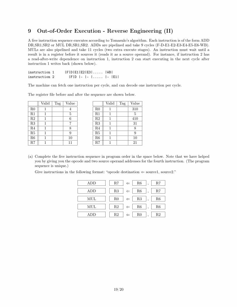
9 Out-of-Order Execution - Reverse Engineering (II)
A five instruction sequence executes according to Tomasulo’s algorithm. Each instruction is of the form ADDDR,SR1,SR2 or MUL DR,SR1,SR2. ADDs are pipelined and take 9 cycles (F-D-E1-E2-E3-E4-E5-E6-WB).MULs are also pipelined and take 11 cycles (two extra execute stages). An instruction must wait until aresult is in a register before it sources it (reads it as a source operand). For instance, if instruction 2 hasa read-after-write dependence on instruction 1, instruction 2 can start executing in the next cycle afterinstruction 1 writes back (shown below).
instruction 1 |F|D|E1|E2|E3|..... |WB|instruction 2 |F|D |- |- |..... |- |E1|
The machine can fetch one instruction per cycle, and can decode one instruction per cycle.
The register file before and after the sequence are shown below.
Valid Tag ValueR0 1 4R1 1 5R2 1 6R3 1 7R4 1 8R5 1 9R6 1 10R7 1 11
Valid Tag ValueR0 1 310R1 1 5R2 1 410R3 1 31R4 1 8R5 1 9R6 1 10R7 1 21
(a) Complete the five instruction sequence in program order in the space below. Note that we have helpedyou by giving you the opcode and two source operand addresses for the fourth instruction. (The programsequence is unique.)
Give instructions in the following format: “opcode destination ⇐ source1, source2.”
ADD R7 ⇐ R6 , R7
ADD R3 ⇐ R6 , R7
MUL R0 ⇐ R3 , R6
MUL R2 ⇐ R6 , R6
ADD R2 ⇐ R0 , R2
19/20

(b) In each cycle, a single instruction is fetched and a single instruction is decoded.
Assume the reservation stations are all initially empty. Put each instruction into the next availablereservation station. For example, the first ADD goes into “a”. The first MUL goes into “x”. Instructionsremain in the reservation stations until they are completed. Show the state of the reservation stationsat the end of cycle 8.
Note: to make it easier for the grader, when allocating source registers to reservation stations, pleasealways have the higher numbered register be assigned to source2.
~ 110 111 ~
x 0~ ~0 y
b 1~ 100 ~
~ 110 101 ~~ 010 ~1 a
a
b
c
+
x
y
z
x
(c) Show the state of the Register Alias Table (Valid, Tag, Value) at the end of cycle 8.
Valid Tag ValueR0 0 x 4R1 1 ~ 5R2 0 c 6R3 0 b 7R4 1 ~ 8R5 1 ~ 9R6 1 ~ 10R7 0 a 11
20/20