1.multilayer pipe. the pipe and its applications1.multilayer pipe. the pipe and its applications the...
TRANSCRIPT
1.MULTILAYER Pipe. The pipe and its applications
The plastics have several advantages, not only on the utilisation level as raw material and final product, but also on a production level.
According to the energetic/environmental point of view, when we observe the production of the raw material, we can see the reduced value that the relation “kg of energy for production/ kg of final product” show to us. As example, the same comparison shows a result of 7 or 8 times higher for copper. Another advantage comparison, more and more important nowadays, is the capability of recycle or re- utilisation, for a new production or use as a combustible.
Adding to this characteristic, we have also high chemical, physical and thermal properties of the final products when compared with metallic pipes. Other advantageous characteristics are, among others, low density, low electrical conductibility, high corrosion and toxicity resistance.
As any product, there are some limitations, as the relation between pressure and working temperatures with inferior results when compared with the metallic pipes; or superior thermal dilations when under the effect of temperature variations.
Therefore, it is easy to understand the reason of the growing utilisation of the plastic pipes in the industrial and domestic installations, for the transport and fluid distribution.
Because of the impossibility of fighting the limitations of plastic pipes as “pure” material, the solution has been to try achieving a commitment between metallic and non-metallic pipes, trying to enhance the inherent properties of each type of pipe.
The multilayer pipe has then appeared, consisting in a joint of plastic material (polyethylene) with a metallic element (aluminium).
Polyethylene characteristics, as a plastic material, are easily recognised. However, it is questionable the use of the aluminium. The aluminium appears in the top of the list of the most versatile metallic materials, with higher resources. The fact that it is used in the food and pharmaceutical industries is an example of that same versatility. The aluminium, besides being inodorous, is impermeable to gases and light.
The MULTILAYER pipe is an extruded pipe. To the interior layer of polyethylene is added a layer of adherent film to allow the placement of the aluminium leaf. This aluminium leaf is laser welded and designated by METALPEX, or by sounds being designated MAXIMETAL.
The aluminium leaf is covered with another layer of adherent film and then a final layer of white polyethylene (bearing in mind the external installations).
Fig1. multilayer constitution
It is therefore easy to conclude that the MULTILAYER pipe combine the plastic pipes advantages to the metallic pipes potentialities.
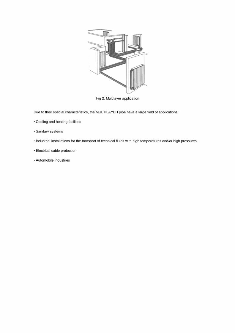
Fig 2. Multilayer application
Due to their special characteristics, the MULTILAYER pipe have a large field of applications:
• Cooling and heating facilities
• Sanitary systems
• Industrial installations for the transport of technical fluids with high temperatures and/or high pressures.
• Electrical cable protection
• Automobile industries

2. METALPEX Characteristics
In chart 1 and 2, we can see the dimension characteristics and associated heights to each model of produced pipe.
METALPEX is produced according to the specification SKZ- HR- 3.12, specification KIWA BRL- K- 536/03 (part E), standard Din 4729 and Duofil specification.
Fig. 3- Multilayer pipe dimension
The following graph shows the range of production of the METALPEX pipe:
The pipe is supplied in 4 meter bars or in coils of 50, 100 and 200 meters for the METALPEX pipes.
The following graph shows the pipe proprieties.

Chart 2- Multilayer Proprieties

3. MULTILAYER advantages
For all that has been presented, the numerous advantages of METALPEX pipe is easily understood.
The most important are:
• High temperature fluid transportation ( 95º C without risk of achieving the 110º C in brief periods) and/or high pressures ( 10 bar)
• Reduced coefficient of thermal conductibility, important for the energetic consumption in heating and also for external condensations in cooling systems.
• Low coefficient of linear expansion, allowing us to consider these pipes at the level of the metallic ones.
• High fluid discharge with reduced loss of friction charge, implying energy savings in relation with the inherent consumption of the fluid circulation. The possibility of incrustations is minimised by the nearly flat inner surface.
• Total anti-oxygen barrier, assured by the aluminium layer, maintaining the same characteristics of the fluids inside the pipes.
• High corrosion resistance due to the double layer of PEX (METALPEX) or to the double layer of PE-RT (MAXIMETAL), which protects the aluminium layer inside and outside, and to the quality of the MULTILAYER fittings that do not allow the metallic contact between the water and the aluminium layer stopping the formation of electrochemical phenomena, assuring a higher durability of the installations and a higher performance.
• Low coefficient of electrical conductibility, reducing the possibility of transmitting electrical power, a characteristic of the metallic pipes.
• Pipes are build with perfectly hygiene materials, increasing the trust in the transportation of clean water or any other fluids for human consumption.
• Reduced level of sound transmission increasing the comfort level, which does not happen in the installations with metallic pipes.
• The high flexibility, allowing manual moulding, achieving permanent and stable forms, together with the METALPEX and MAXIMETAL system composed by a wide range of easy handling fittings for a simple connection and installation, really reduce the execution time of the installation when compared, for example, with an installation in welded copper.
• Low weight which reduces the risks of transportation and installation of the pipes.
4. MULTILAYER considerations
To understand the advantages in the use of the MULTILAYER, some recommendations should be taken into consideration during handling, in order to maintain its proprieties:
• The pipe should be stored and/or transported always in places protected from the weather
• The package should be only removed in the moment of the installation, keeping it intact in order to keep the good state of the pipe.
• The bars and the coils should be stored in a correct way, without the possibility of falls, at a maximum of 1.5m
• The formation of ice inside the pipe should be avoided ( for example, during the hydraulic rehearsal of the installation the exterior temperature at night can cause this freezing) which could lead to additional efforts and damage the pipe when changing phase occurs.
• Never put sharp elements in contact with the pipe surface because it can create cuts or damages that will cause the appearance of cracks.
• Do not .use heat to mould the pipe. Always use the correct equipment specified for the effect. This way, also a higher uniformization of the pipe section is achieved.
• The cut of the pipe should always be made in a perpendicular way to the geriatric and with proper equipment ( for ex. Cutting scissors).
At the end of each installation, a stagnation rehearsal, to detect and verify any possible leaking, should be
made. This rehearsal should be made with a 1,5 times higher pressure than the working pressure, and it
could be used water, gas or any other designated test fluid.

5. METALPEX and MAXIMETAL systems
The METALPEX and MAXIMETAL pipe has a large range of fittings, mechanical opening fittings or mechanical pressure fittings associated, to install the system. DUOFIL is always disposal for helping in finding the best solution for each case.
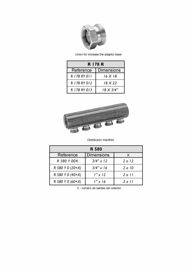


Fig.4. some examples of how the multilayer system can be use

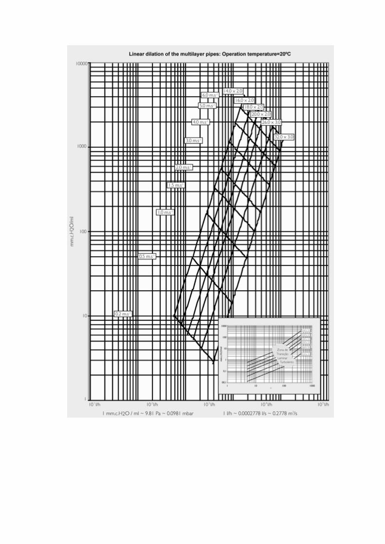
6. Load losses
The load losses for friction are calculated taking under consideration the dimension of the pumping system of the hydraulic installation. Easily it is understood that lower load losses lead to smaller equipment and cheaper ones, but also to pumping inferior energy consumption.
Chart 1, in next page, shows the load losses by linear meter of METALPEX / MAXIMETAL pipe installation, in the available range. It is necessary to keep in mind that this graphic points out values for working temperatures of 20ºC.
Chart 3, in the bottom of the page, allow us to see the load losses shown in graphic 1, for an indicated water flow and pipe. We can use the coefficient of temperature variation ( Kvt), showed in chart 3, to determinate the real load losses to the working temperature of the installation. The formula is:
Chart3. temperature variations coefficients. For other values of operation temperatures and transportation speed, we could use the
interpolation ( cubical) spit the non linear variation.
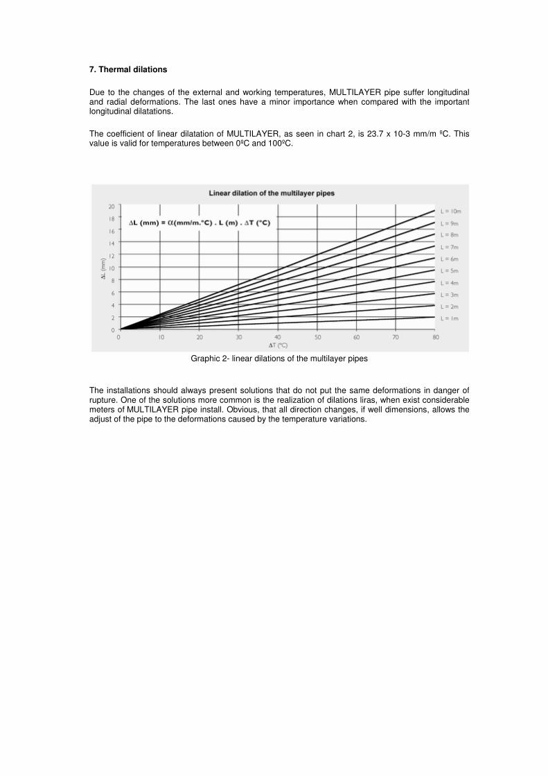
7. Thermal dilations
Due to the changes of the external and working temperatures, MULTILAYER pipe suffer longitudinal and radial deformations. The last ones have a minor importance when compared with the important longitudinal dilatations.
The coefficient of linear dilatation of MULTILAYER, as seen in chart 2, is 23.7 x 10⁻³ mm/m ºC. This value is valid for temperatures between 0ºC and 100ºC.
Graphic 2- linear dilations of the multilayer pipes
The installations should always present solutions that do not put the same deformations in danger of rupture. One of the solutions more common is the realization of dilations liras, when exist considerable meters of MULTILAYER pipe install. Obvious, that all direction changes, if well dimensions, allows the adjust of the pipe to the deformations caused by the temperature variations.

Graphic 3. different linear dilations of the several materials used in the pipes buildings, for a strait line
with L=10 m and a temperature difference of 50ºC

Graphic 4. compensation arms of the linear dilations for the pipe.
As we can conclude by figure 5.1 and 5.2 of graph 4, for each meters L (measure starting for a point of rigid fix ion), it should be install a dilatation arm whose dimension must have a minimum value in Lb measure. This values are a plicate also in others situations similar to the dilatations liras as the situations shows in the next page.
Fig. 5.1. dilation lira with false selling
Fig. 5.2. “courette” vertical distribution

Fig 5.3. installation
Let us consider a situation of an installation with false ceiling as in image 5.3.. It is necessary to take into consideration some measures of the installation, so that the expansions caused by heating or cooling of the fluid, for the working temperature, does not cause excessive efforts, either in the MULTILAYER pipe and fittings, and consequent ruptures.
Therefore, measure A must always have a higher value to the one considered for the dilatation arm Lb, using graph 3, because the crossing hole is equal to the existence of a support slide. In case of not “existing” a wall at the level of the false ceiling, this measure stops automatically needing to have a minimum value to respect.
The B measure is very important in heating situations. This value must be superior to the length variation value (∆L) presented by length L of the MULTILAYER pipe. In case this does not happen, when proceeding to the heating of the fluid circulating inside the pipe, this will expand and the horizontal distribution pipe to the living room will be compressed against the ceiling.
At last, and opposite to B measure, C measure is important in cooling installations or when the fluid, due to the variation of the exterior temperature, has the tendency to cool down. Therefore, is value must be higher to the contraction (∆L) value previewed for MULTILAYER pipe of L length.

8. Fixation Points
The fixation or support points of an installation made with MULTILAYER must not exceed the values presented in chart 4. Please notice that this value shows simple supports and do not intend to indicate the fixations points.
The values presented by chart 4 are not valid for inside wall installations.
There are some rules for the execution of pipe support as showed bellow:
• All supports must be placed as near as possible of the concentrated loads, such us valves or manifolds.
• In direction changes in a horizontal level, the supports should be located as near as possible of the bends or Ts, at a distance of ¾ of the maximum value for straight lines (chart 4).
• In any case should be placed supports in bends so that the rigidity of the anchorage system is increased.
• In the direction changes in the vertical plan, a support should be placed in the horizontal inferior part of the vertical column, as near as possible of the bend (this is the support that will sustain the weight of the vertical installation). The supports in the vertical part will “guide” the pipe. These guides should be separated about two times the maximum distance previewed for the horizontal parts.
• There should be a support in the superior half of the vertical path to avoid the pipe flexion.
• The supports should be always installed in resistant structures that can sustain the support and pipe themselves, trying to avoid special support structures.
• When there is a cross over of two pipes, the fixation points should be at the crossing point, as indicated in image 7.
It is very important to make a preview study of the supports to be considered, taking under consideration the dilatations and the weights of the installation.
In the installations with pipes inside the wall, it is so or even more important to consider its supports, and should be created the necessary conditions in the openings of the pipe installation, so that it may expand or contract due to the temperature variation.

9. Thermal Losses
The transport effect of a fluid at a different temperature from the ambient one implies a heat transmission in the MULTILAYER pipe walls and therefore a temperature variation of the transported fluid. In a simple way, for an infinite length, the final temperature in the exit of a installation would be equal to the exterior temperature of the air in contact with the installation.
Such phenomenon is important to estimate the water temperature value in a specific installation point or, as this case shows, the temperature value at the exit of the installation. Another important phenomenon, inherent to the transport of fluids at temperatures inferior to the external one, is the appearing of condensations in the external pipe surface that leads to the deterioration and the appearing of “humidity” in the house walls when the pipes are installed inside them.
In conclusion, the thermal losses lead to the inefficiency of a system. As an example, when we compare the performance of a MULTILAYER with a copper pipe, we can see that for the same working temperatures, either of the inside fluid or the external air, and considering similar values for the isolation thickness, the thermal losses are inferior to the installation using a multilayer system.
Graphic 5. percentage diminution area of thermal losses by substituting an cupper by an multilayer pipe,
geometric and isolation thinness equal, for the same operation condition.
On the other hand, when comparing the isolation thickness necessary for the same working conditions and for the same thermal losses, the results are also very favourable to the METALPEX / MAXIMETAL pipes.
Graphic 6. percentage values area regarding the isolation thinness diminution by substituting a cupper
pipe for a multilayer one, geometrical equal, AT between the average temperature of the liquid to transport and the external air temperature, and equal thermal losses.
The presented comparison has advantages in two levels: installation cost and bigger perception of the diminution of the thermal losses when METALPEX / MAXIMETAL pipe is used instead of the copper pipes. Graphic 5 allow us to observe the energetic gains inherent to the use of METALPEX / MAXIMETAL pipe.
The MULTILAYER pipe, offers obvious guarantees of energetic savings and, therefore, an energy invoice reduction by increasing the efficiency of the installation.

Graph 7, after same theoretical simplification, allow us to estimate a value for the water temperature transported inside the METALPEX / MAXIMETAL pipe. This temperatures changes, obviously, according to the fluid flow (transport speed and pipe diameter), with the water temperature available by the heating system, with external air temperature value and its agitation ( for the situation in the graphic it was considered an external temperature of 20º C) and with the number of meters of the installed pipe.
Chart 5 show us the minimum value of the thermal isolation thinness to install.
Chart5. minimum isolation thinness to stop the appearing of the air condensation phenomena’s in the
external suffer of the pipes

10. Application example
let us consider the next real situation.
A METALPEX / MAXIMETAL pipe 16, 0x2, 0 with 70 meters longer, transport 400l/h of water at a medium temperature of 80º. We should consider also an external temperature of 20ºC.
The calculus should begin by determinate the load loss of water, using graphic 1, we could determinate the exact value for an operation temperature of 20ºC.
Trough the temperature variation coefficient, we could calculate the load loss for 80ºC
So,
Now, to achieve the total value regarding the load loss, we should determinate the linear dilations effect on the length do pipe. Considering fixes supports distant 10 meters of each other and making dilatation liras exactly on the middle of each trunk, we can calculate the real pipe length when the water achieve 80ºC.
This way, trough graphic 2,
For a 70m length, the linear dilatation will be,
Now, we will have to considerer all the dilatation lengths of each lira previous introduce.
Each linear trunk with 10 meters longer between the fixes supports, has one dilatation lira witch arm can be determinate using graphic 4. Advice that a dilatation with half of the value found for the pipe dilatation between fixes supports.

Each lira has toe dilatation arms, existing 7 liras in the installation consider, the additional length will be,
Finally, the total length will be,
This way, the total loss that will give us the barometrical high, for gravity or for using a pomp group, will be,
At last, and assuming that the temperature at entrance is 80ºC we can, trough graphic 7, estimate the water temperature value after running 70meters ( 74,65 real meters at 80ºC) of the installation.
11. Installation. Different ways of MULTILAYER pipe application
Follow, we will be able to see how to install multilayer pipes and their connection with the fittings already mention. To this connection, we call METALPEX / MAXIMETAL system.
We should always remember chapter 4, due to the considerations in the pipe installation.
As mention, the multilayer system has two forms of installations:
Ø Mechanical opening fittings ( for example: R 179 AM fitting)
Ø Mechanical pressure ( for example: RP 102 fitting)
All the fittings have a plastic protection, avoiding the contact between the metal in the fitting and the aluminium that exists in the pipe, pushing away the electrochemical phenomenon.
Spite the differences related this two methods, they have equal operations. So, the following description coverage the two methods, existing differences correctly mention.
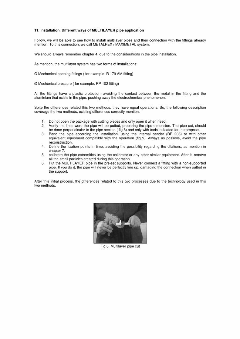
1. Do not open the package with cutting pieces and only open it when need. 2. Verify the lines were the pipe will be putted, preparing the pipe dimension. The pipe cut, should
be done perpendicular to the pipe section ( fig 8) and only with tools indicated for the propose. 3. Bend the pipe according the installation, using the internal bender (RP 208) or with other
equivalent equipment compatibly with the operation (fig 9). Always as possible, avoid the pipe reconstruction.
4. Define the fixation points in time, avoiding the possibility regarding the dilations, as mention in chapter 7.
5. calibrate the pipe extremities using the calibrator or any other similar equipment. After it, remove all the small particles created during this operation.
6. Put the MULTILAYER pipe in the pre-set supports. Never connect a fitting with a non-supported pipe. If you do it, the pipe will never be perfectly line up, damaging the connection when putted in the support.
After this initial process, the differences related to this two processes due to the technology used in this two methods.
Fig 8. Multilayer pipe cut

Fig 9. shaping
Fig 10. Pipe calibration
11.1 Mechanical Pressure
After calibrating the pipe, a R179 AM fitting is placed in the pipe as illustrated in image 11. A special care is important with the plastic ring so there is no contact between metallic elements. The adapter is put inside the pipe and the pressure is made to the element in question ( manifold, radiator,…)
The rest of the fittings allow us to adapt the coupling dimensional systems to the dimensions of the RP 179 AM fitting.
Fig 11. Fitting placement
Fig 12. fitting adjustment

11.2 Press-fitting
In this process, a compression equipment is necessary ( RP 200). After placing the correct clamp to the pipe dimension and the correct fitting ( fig. 13), it is necessary to adjust the compression jaw ( fig 14) to carry out the operation. After finishing the compression, the jaw is removed and the fitting guarantees the installation.
All the range of press-fittings, identified by the letters RP, does not allow the contact between the metallic elements in the pipe and in the fittings.
Fig 13. fitting placement
Fig 14. Compression operation
11.3 Other Considerations
At the end of each installation, before beginning the full work of the same, a hydraulic test should be made
to check any leakage of fluid. This test should be made by putting all the installation to a pressure non
inferior to 1.5 times the foreseen working pressure, for at least 24 hours. The test fluid could be water, gas,
or any other fluid designated for the effect.