1m60 user's manual - daheng...
TRANSCRIPT

PANTERA 22M
Camera User’s Manual
CA-40-22M03-00-L
Pro
gressiv
e S
ca
n M
on
och
rom
e C
am
era
20-Aug-11
Hwww.teledynedalsa.com
03-032-20049-02 H

2 PANTERA 22M User’s Manual
Teledyne DALSA 03-032-20049-02
About Teledyne Technologies and Teledyne DALSA, Inc.
Teledyne Technologies is a lead ing provider of sophisticated electronic subsystems, instrumentation and
communication products, engineered systems, aerospace engines, and energy and power generation
systems. Teledyne Technologies’ operations are primarily located in the United States, the United
Kingdom and Mexico. For more information, visit Teledyne Technologies’ website at www.teledyne.com.
Teledyne DALSA, a Teledyne Technologies company, is an international leader in high performance
d igital imaging and semiconductors with approximately 1,000 employees worldwide, headquartered in
Waterloo, Ontario, Canada. Established in 1980, the company designs, develops, manufactures and
markets d igital imaging products and solutions, in addition to provid ing MEMS products and services.
For more information, visit Teledyne DALSA’s website at www.teledynedalsa.com.
Support
For further information not included in this manual, or for information on Teledyne DALSA’s extensive
line of image sensing products, please contact:
North America
605 McMurray Rd
Waterloo, ON N2V 2E9
Canada
Tel: 519 886 6000
Fax: 519 886 8023
www.teledynedalsa.com
Europe
Breslauer Str. 34
D-82194 Gröbenzell (Munich)
Germany
Tel: +49 - 8142 – 46770
Fax: +49 - 8142 – 467746
www.teledynedalsa.com
Asia Pacific
Ikebukuro East 13F
3-4-3 Higashi-Ikebukuro
Toshima-ku, Tokyo 170-0013
Japan
Tel: 81 3 5960 6353
Fax: 81 3 5960 6354 (fax)
www.teledynedalsa.com

PANTERA 22M User’s Manual 3
Teledyne DALSA 03-032-20049-02
Contents
Introduction to the PANTERA 22M Area/TDI Scan Camera ____________________________ 5
1.1 Camera Highlights ....................................................................................................................................................... 5
1.2 Image Sensor ............................................................................................................................................................... 6
1.3 Camera Performance Specifications ............................................................................................................................ 7
1.4 Blemish specification ................................................................................................................................................... 9
Camera Hardware Interface ________________________________________________ 11
2.1 Installation Overview ................................................................................................................................................... 11
2.2 Input/Output Connectors and LED ............................................................................................................................... 11
Software Interface: How to Control the Camera __________________________________ 17
3.1 Communications Protocol Overview ............................................................................................................................ 17
3.2 Overview: Setting up the Camera to Send Commands ................................................................................................ 18
3.3 Saving and Restoring Settings ..................................................................................................................................... 19
3.4 Setting Operating Mode .............................................................................................................................................. 19
3.5 Setting Exposure Mode and Exposure Time (Area Mode) ........................................................................................... 19
3.6 TDI Mode ..................................................................................................................................................................... 24
3.7 Setting Sync Frequency (TDI and Area Mode) ............................................................................................................. 25
3.8 Switching between Area and TDI mode (TDI/Area Mode) .......................................................................................... 26
3.9 Setting the Camera Link Data Mode ........................................................................................................................... 26
3.10 Setting Baud Rate ...................................................................................................................................................... 27
3.11 Setting Gains ............................................................................................................................................................. 27
3.12 Monitoring the Camera ............................................................................................................................................. 29
3.13 Rebooting the Camera ............................................................................................................................................... 29
3.14 Setting the Video Mode and Generating Test Patterns ............................................................................................. 29
Optical and Mechanical Considerations ________________________________________ 31
4.1 Mechanical Interface .................................................................................................................................................... 31
4.2 Mounting the Camera .................................................................................................................................................. 32
4.3 Thermal Management ................................................................................................................................................. 32
4.4 Environment ................................................................................................................................................................ 32
Cleaning and Maintenance ________________________________________________ 33
5.1 Cleaning ....................................................................................................................................................................... 33
5.2 Maintenance ................................................................................................................................................................ 35
Troubleshooting ________________________________________________________ 37
6.1 Common Solutions ....................................................................................................................................................... 37
6.2 Troubleshooting Using the Serial Interface ................................................................................................................. 38
6.3 Specific Solutions ......................................................................................................................................................... 39
6.4 Product Support ........................................................................................................................................................... 40

4 PANTERA 22M User’s Manual
Teledyne DALSA 03-032-20049-02
Camera Link™ Reference, Configuration and Image Construction ______________________ 41
Commands and Error Handling _____________________________________________ 45
Index _______________________________________________________________ 49
Revision History ________________________________________________________ 51

PANTERA 22M User’s Manual 5
Teledyne DALSA 03-032-20049-02
1 Introduction to the
PANTERA 22M Area/TDI
Scan Camera
1.1 Camera Highlights
Features • 4008(H) x 5344(V) resolu tion, fu ll frame CCD architecture
• The PANTERA 22M offers up to 3.6 fps, 4 outputs at fu ll resolu tion, 27 MHz data rate
• Up to 12 bit d igitization
• Small gain steps to achieve extremely low seam mismatch between taps
• High sensitivity with low dark current
• Area or TDI mode
• Exposure control and antiblooming
• Asynchronous image capture, externally triggerable
• Tap to tap matching
• 100% fill factor
• Single 12VDC power supply
Programmability • Simple ASCII protocol controls gain, offset, frame rates, trigger mode, test pattern
output, and camera d iagnostics
• Serial interface (ASCII, 9600 baud, ad justable up to 115200), through Camera Link™
Description The PANTERA 22M digital cameras provide high-sensitivity 12 bit images with a 4008 x
5344 spatial resolu tion. The cameras use the fu ll frame FTF4052M sensor to
simultaneously achieve outstanding resolu tion and gray scale characteristics. A square
pixel format and high fill factor provide superior, quantifiable image quality even at low
light levels.
6 PANTERA 22M User’s Manual
Teledyne DALSA 03-032-20049-02
Applications The PANTERA 22M are outstanding performers in fast, very high resolu tion
applications. 12 bit performance provides up to 4096 d istinct gray levels—perfect for
applications with large interscene light variations. The low -noise, d igitized video signal
also makes the camera an excellent choice where low contrast images must be captured in
challenging applications.
Specific applications include:
• Flat panel inspection
• Microscopy
• Aerial reconnaissance
• Medical and non-destructive test x-ray
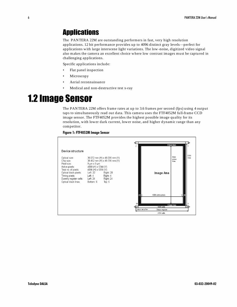
1.2 Image Sensor The PANTERA 22M offers frame rates at up to 3.6 frames per second (fps) using 4 output
taps to simultaneously read out data. This camera uses the FTF4052M full-frame CCD
image sensor. The FTF4052M provides the highest possible image quality for its
resolu tion, with lower dark current, lower noise, and higher dynamic range than any
competitor.
Figure 1: FTF4052M Image Sensor
PANTERA 22M User’s Manual 7
Teledyne DALSA 03-032-20049-02
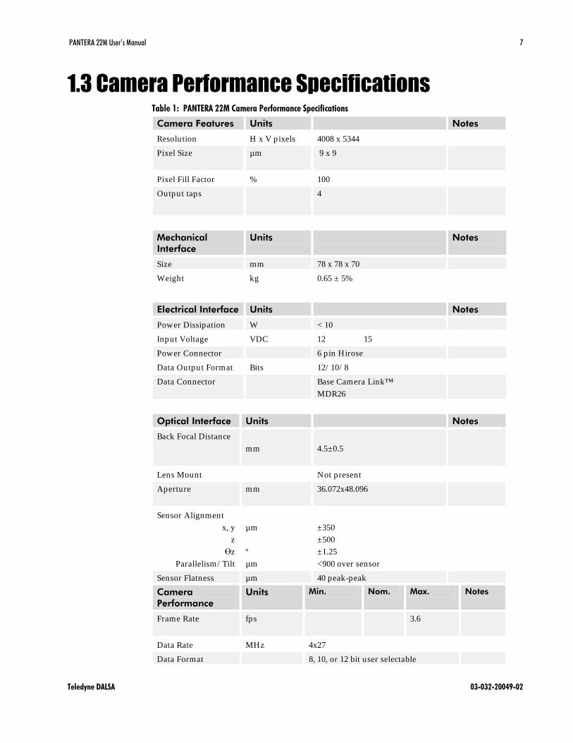
1.3 Camera Performance Specifications Table 1: PANTERA 22M Camera Performance Specifications
Camera Features Units Notes
Resolution H x V pixels 4008 x 5344
Pixel Size µm 9 x 9
Pixel Fill Factor % 100
Output taps 4
Mechanical
Interface
Units Notes
Size mm 78 x 78 x 70
Weight kg 0.65 ± 5%
Electrical Interface Units Notes
Power Dissipation W < 10
Input Voltage VDC 12 15
Power Connector 6 pin Hirose
Data Output Format Bits 12/ 10/ 8
Data Connector Base Camera Link™
MDR26
Optical Interface Units Notes
Back Focal Distance
mm
4.5±0.5
Lens Mount Not present
Aperture mm 36.072x48.096
Sensor Alignment
x, y
z
z
Parallelism/ Tilt
µm
º
µm
±350
±500
±1.25
<900 over sensor
Sensor Flatness µm 40 peak-peak
Camera
Performance
Units Min. Nom. Max. Notes
Frame Rate
fps 3.6
Data Rate MHz 4x27
Data Format 8, 10, or 12 bit user selectable

8 PANTERA 22M User’s Manual
Teledyne DALSA 03-032-20049-02
Operating Temp °C -10 50 At front
plate
Gain Range dB 0 24
Dynamic Range dB 63
Pixel Response Non-
Uniformity (PRNU)
DN rms 5
Fixed Pattern Noise
(FPN)
DN rms 3
Sat. Output
Amplitude
DN 3680 3840 4000 1
DC Offset DN 80 160 240 1
Antiblooming >100x 1
Responsivity DN/ (nJ/ cm P
2P) 19 20 21 12-bit
@530nm
Power Up Duration sec 10
Power Up
Stabilization time
min 30
Regulatory
Regulatory
Compliance
None
Notes:
1. Nominal output, 100ms exposure time. Light source: broadband quartz halogen,
3200K, 750nm and IR cutoff filter.
Figure 2 PANTERA 22M Spectral Responsivity

PANTERA 22M User’s Manual 9
Teledyne DALSA 03-032-20049-02
1.4 Blemish specification PANTERA 22M camera includes an FTF4052M CCD image sensor, industrial grade.
Blemish specification is presented below.
Below table shows FTF4052M Sensor Blemish Specifications, maximum number of
blemishes permitted .
Description IG (industrial grade)
Pixel defects 100
Cluster defects 12
Spot defects 0
Column defects 1
Row defects 0
Definition of blemishes
Pixel defect
Pixel whose signal, at nominal light (illumination at 50% of the linear range), deviates
more than ±30% from its neighbouring pixels. Pixel whose signal, in dark, deviates more
than 250mV from its neighbouring pixels.
Cluster defect
A grouping of at most 5 pixel defects within a sub-area of 3*3 pixels.
Spot defect
A grouping of more than 5 p ixel defects within a sub-area of 3*3 pixels.
Column defect
A column which has more than 8 pixel defects in a 1*12 kernel.
Column defects must be horizontally separated by 3 good columns.
Row defect
A horizontal grouping of more than 8 pixel defects between at least 2 good pixels on both
sides, where single good pixels between 2 defective pixels are considered as defective.
Test conditions
Temperature: 60°C
Integration Time: 100ms

10 PANTERA 22M User’s Manual
Teledyne DALSA 03-032-20049-02

PANTERA 22M User’s Manual 11
Teledyne DALSA 03-032-20049-02
2 Camera Hardware
Interface
2.1 Installation Overview In order to set up your camera, you should take these initial steps:
1. Power down all equipment.
2. Following the manufacturer’s instructions, install the frame grabber (if
applicable). TBe sure to observe all static precautions
3. Install any necessary imaging software.
4. Before connecting power to the camera, test all power supplies. TEnsure that all the
correct voltages are present at the camera end of the power cable T (The Camera Performance
Specifications on page 6 list appropriate voltages). Power supplies must meet the
requirements defined in HT2.2.3 Power Connector TH Power Input.
5. Inspect all cables and connectors prior to installation. Do not use damaged cables
or connectors or the camera may be damaged.
6. Connect data, serial interface, and power cables.
7. After connecting cables, apply power to the camera. After a few seconds, the LED
on the back of the camera should be green to indicate that the camera is operating
and ready to receive commands.
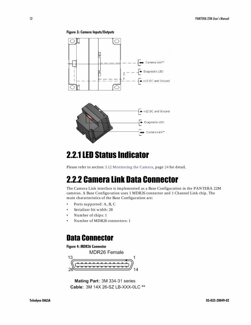
2.2 Input/Output Connectors and LED The camera uses a:
• Diagnostic LED for monitoring the camera. See LED Status Indicator section below
for details.
• High-density 26-pin MDR26 connector for Camera Link control signals, data signals,
and serial communications. Refer to Figure 4: MDR26 Connector for pin descriptions.
• 6-pin Hirose connector for power. Refer to HT2.2.3 Power Connector TH for pin
descriptions.
This installation overview
assumes you have not installed
any system components yet.
12 PANTERA 22M User’s Manual
Teledyne DALSA 03-032-20049-02
Figure 3: Camera Inputs/Outputs
2.2.1 LED Status Indicator
Please refer to section HT3.12 Monitoring the Camera TH, page T24TH for detail.
2.2.2 Camera Link Data Connector The Camera Link interface is implemented as a Base Configuration in the PANTERA 22M
cameras. A Base Configuration uses 1 MDR26 connector and 1 Channel Link chip. The
main characteristics of the Base Configuration are:
• Ports supported: A, B, C
• Serializer bit width: 28
• Number of chips: 1
• Number of MDR26 connectors: 1
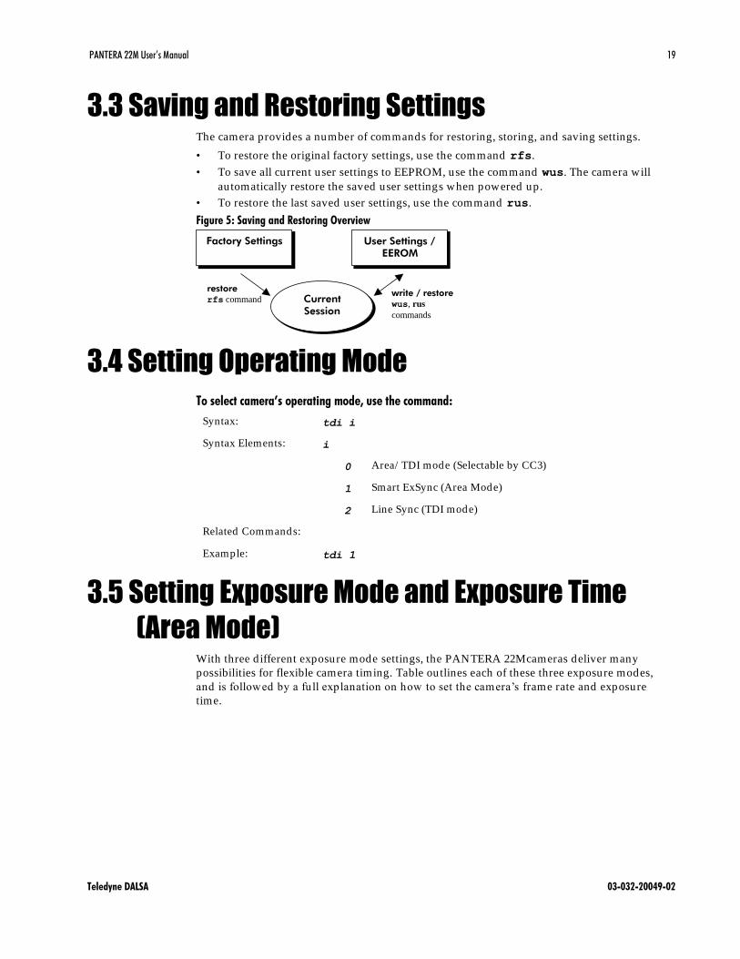
Data Connector Figure 4: MDR26 Connector

PANTERA 22M User’s Manual 13
Teledyne DALSA 03-032-20049-02
Table 2: MDR26 Connector Reference
Item Value Item Value
Pinout BASE Pinout BASE
1 GND 14 GND
2 X0- 15 X0+
3 X1- 16 X1+
4 X2- 17 X2+
5 Xclk- 18 Xclk+
6 X3- 19 X3+
7 SERTC+ 20 SERTC-
8 SERTFG- 21 SERTFG+
9 CC1- 22 CC1+
10 CC2+ 23 CC2-
11 CC3- 24 CC3+
12 CC4+ 25 CC4-
13 GND 26 GND
TNotes:
*Exterior Overshield is connected to the shells of the connectors on both ends.
**3M part 14X26-SZLB-XXX-0LC is a complete cable assembly, including connectors.
Unused pairs should be terminated in 100 ohms at both ends of the cable.
Table 3: Camera Control Configuration
Signal Configuration
CC1 Smart EXSYNC(Area Mode)
CC2 Line Sync (TDI mode)
CC3 Area/ TDI mode
CC4 Spare
Digital Data The camera d igitizes internally to 12 bits and has a user selectable output of 8, 10, or 12
bits in LVDS format on the Camera Link connector. You can select the output using the
clm command. For details, see section3.9 Setting the Camera Link Data Mode.
Data Clocking Signals These signals indicate when data is valid , allowing you to clock the data from the camera
to your acquisition system. These signals are part of the Camera Link configuration and
you should refer to the Teledyne DALSA Camera Link Implementation Road Map,
available with contacting Teledyne DALSA Technical support, for the standard location
of these signals:
Clocking Signal Indicates
LVAL (high) Outputting valid line
DVAL (high) Valid data
STROBE (rising edge) Valid data
FVAL (high) Outputting valid frame
IMPORTANT:
This camera’s data
should be sampled on
the rising edge of
STROBE.

14 PANTERA 22M User’s Manual
Teledyne DALSA 03-032-20049-02
See Appendix A for the complete Camera Link timing, Teledyne DALSA Camera Link
configuration table, and contact Teledyne DALSA Technical support, for the official
Camera Link document.
Input Signals The camera accepts an EXSYNC control input through the Camera Link MDR26F
connector.
EXSYNC (Triggers Readout) For high speed communication the CC lines of camera link will be used .
The table below shows high speed controls:
Table 4: PANTERA 22M Camera Control Configuration
Camera Link
input
Function Note
CC1 Smart ExSync (Frame trigger
and exposure control)
Will be ignored in TDI
mode
CC2 Line sync TDI mode only
CC3 0 - Area mode, split vertical
transfer.
1 - TDI mode, one-way
transfer
The direction of one-way
transfer is set by
software
2.2.3 Power Connector
Pin Description Pin Description
1 +12V 4 GND
2 +12V 5 GND
3 +12V 6 GND
The camera requires a single voltage input (+12VDC to +15VDC). The camera meets all
performance specifications using standard switching power supplies, although well -
regulated linear supplies provide optimum performance.
When setting up the camera’s power supplies follow these guidelines:
• Protect the camera with a fast-blow fuse between power supply and camera.
• Do not use the shield on a multi-conductor cable for ground.
• Keep leads as short as possible to reduce voltage drop.
• Use high-quality linear supplies to minimize noise.
Note: Performance specifications are not guaranteed if your power supply does not meet
these requirements

PANTERA 22M User’s Manual 15
Teledyne DALSA 03-032-20049-02
WARNING: It is extremely important that you apply the appropriate voltages to your camera.
Incorrect voltages will damage the camera. Protect the camera with a fast-blow fuse between
power supply and camera.
Visit the www.teledynedalsa.com Web site for a list of companies that make power
supplies that meet the camera’s requirements. The companies listed should not be
considered the only choices.

16 PANTERA 22M User’s Manual
Teledyne DALSA 03-032-20049-02

PANTERA 22M User’s Manual 17
Teledyne DALSA 03-032-20049-02
3 Software Interface: How
to Control the Camera
All camera features can be controlled through the serial interface. The camera can also be
used without the serial interface after it has been set up correctly. This chapter explains
the most commonly used and important commands, including:
HT3.3 Saving and Restoring Settings TH
HT3.4 Setting Operating Mode TH
HT3.5 Setting Exposure Mode and Exposure Time (Area Mode) TH
HT3.6 Setting Scan Direction and Sync Mode (TDI Mode) TH
HT3.7 Setting Sync Frequency (TDI and Area Mode) TH
HT3.8 Switching between area and TDI mode (TDI/ Area Mode) TH
HT3.9 Setting the Camera Link Data Mode TH
HT3.10 Setting Baud Rate TH
HT3.11 Setting Gains TH
HT3.12 Monitoring the Camera TH
HT3.13 Rebooting the Camera TH
HT3.14 Setting the Video Mode and Generating Test Patterns TH
The serial interface uses a simple ASCII-based protocol. For a complete list of all available
commands, refer to the Communications Protocol on page HTCommands and Error
Handling TH.
Online Help For quick help, the camera can return all available commands and parameters through
the serial interface. To generate this list, send the command Th T to the camera.
Retrieving Camera Settings To read current camera settings, send the command gcp.
3.1 Communications Protocol Overview
Serial Protocol Defaults: • 8 data bits
i
This chapter outlines the
more commonly used
commands. See
Appendix B for a list of
all available commands.

18 PANTERA 22M User’s Manual
Teledyne DALSA 03-032-20049-02
• 1 stop bit
• No parity
• No flow control
• 9.6Kbps
• Camera does not echo characters
When entering commands, remember that:
• A carriage return (CR) ends each command. The linefeed character is ignored .
• The camera will answer each command with either "OK >" or "Error x: Error Message
>". The ">" is always the last character sent by the camera.
• The following parameters are used throughout the manual:
i = integer
f = float
t = tap
[ ] = optional parameter
3.2 Overview: Setting up the Camera to Send
Commands The following steps describe how to begin using the PANTERA 22M and commands.
1. If you have not already set up your camera cables, connect your cables as described
in section HT2.1 Installation Overview TH.
2. Using a terminal program (e.g., Microsoft HyperTerminal), open a terminal window.
Note: In order to communicate with the camera, a serial connection in the Camera
Link cable needs to be established. The framegrabber manufacturers should be able
to provide a solu tion in order to communicate through this serial link. The terminal
software can be also provided by the framegrabber manufacturer. Standard terminal
software such as HyperTerminal can be used in case if COM port is allocated by the
framegrabber.
Terminal should be set at 9600 baud during the camera power up.
3. When the terminal window is set up, power on the camera.
4. The boot-up message should appear on the terminal window:
Configuration Successful.
OK>
You can now communicate with the camera through the terminal using the software
commands described in this manual.
5. Set up the framegrabber to receive the data. Following the framegrabber
manufacturer’s instructions, set up the parameters described in the Camera Link™
Configuration Table on page 42.
6. Once the framegrabber is set up for data processing and the camera is powered up,
run your image processing software. You should be able to see an image from the
camera when exposed to a light source.
7. You can now set the other camera parameters described in this chapter.
PANTERA 22M User’s Manual 19
Teledyne DALSA 03-032-20049-02
3.3 Saving and Restoring Settings The camera provides a number of commands for restoring, storing, and saving settings.
• To restore the original factory settings, use the command Trfs T.
• To save all current user settings to EEPROM, use the command Twus T. The camera will
au tomatically restore the saved user settings when powered up.
• To restore the last saved user settings, use the command Trus T.
Figure 5: Saving and Restoring Overview
write / restore
wus, rus
commands
restore
rfs command Current
Session
Factory Settings User Settings /
EEROM
3.4 Setting Operating Mode
To select camera’s operating mode, use the command:
Syntax: tdi i
Syntax Elements: i
0 Area/ TDI mode (Selectable by CC3)
1 Smart ExSync (Area Mode)
2 Line Sync (TDI mode)
Related Commands:
Example: tdi 1
3.5 Setting Exposure Mode and Exposure Time
(Area Mode) With three d ifferent exposure mode settings, the PANTERA 22Mcameras deliver many
possibilities for flexible camera timing. Table outlines each of these three exposure modes,
and is followed by a fu ll explanation on how to set the camera’s frame rate and exposure
time.
20 PANTERA 22M User’s Manual
Teledyne DALSA 03-032-20049-02
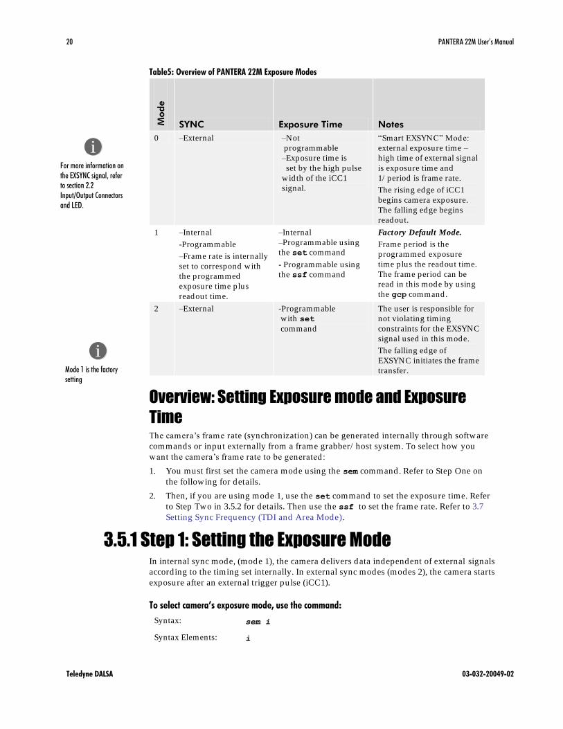
Table5: Overview of PANTERA 22M Exposure Modes
Mod
e
SYNC Exposure Time Notes
0 –External –Not
programmable
–Exposure time is
set by the high pulse
wid th of the iCC1
signal.
―Smart EXSYNC‖ Mode:
external exposure time –
high time of external signal
is exposure time and
1/ period is frame rate.
The rising edge of iCC1
begins camera exposure.
The falling edge begins
readout.
1 –Internal
-Programmable
–Frame rate is internally
set to correspond with
the programmed
exposure time plus
readout time.
–Internal
–Programmable using
the set command
- Programmable using
the ssf command
Factory Default Mode.
Frame period is the
programmed exposure
time plus the readout time.
The frame period can be
read in this mode by using
the gcp command.
2 –External -Programmable
with set
command
The user is responsible for
not violating timing
constraints for the EXSYNC
signal used in this mode.
The falling edge of
EXSYNC initiates the frame
transfer.
Overview: Setting Exposure mode and Exposure
Time The camera’s frame rate (synchronization) can be generated internally through software
commands or input externally from a frame grabber/ host system. To select how you
want the camera’s frame rate to be generated:
1. You must first set the camera mode using the sem command. Refer to Step One on
the following for details.
2. Then, if you are using mode 1, use the Tset T command to set the exposure time. Refer
to Step Two in 3.5.2 for details. Then use the Tssf Tto set the frame rate. Refer to HT3.7
Setting Sync Frequency (TDI and Area Mode) TH.
3.5.1 Step 1: Setting the Exposure Mode In internal sync mode, (mode 1), the camera delivers data independent of external signals
according to the timing set internally. In external sync modes (modes 2), the camera starts
exposure after an external trigger pulse (iCC1).
To select camera’s exposure mode, use the command:
Syntax: sem i
Syntax Elements: i
i
Mode 1 is the factory
setting
i
For more information on
the EXSYNC signal, refer
to section 2.2
Input/Output Connectors
and LED.

PANTERA 22M User’s Manual 21
Teledyne DALSA 03-032-20049-02
0 Smart ExSync (Area Mode)
1 Frame Sync Internal, Exposure Internal
2 Frame Sync External, Exposure Internal
Notes: To obtain the current value of the exposure mode, use the
command Tgcp T.
Related Commands: set
Example: sem 1
Mode 0: Smart EXSYNC, External Frame Rate and
Exposure Time
Figure5. Area mode timing diagram
The below table shows our recommended timing values,
Timing Type Recommended
value
Remarks
T1 Variable >276 ms Frame period , maximum
frame rate = 3.6 frames/ sec
T2 Variable 10 us +
exposure time
iCC1 high length
T3 Typical 718.8 us iCC1 falling edge to FVAL
start
T4 Typical 275.3 ms FVAL length for one frame

22 PANTERA 22M User’s Manual
Teledyne DALSA 03-032-20049-02
T5 Typical 27 us FVAL start to LVAL start
T6 Typical 74.22 us LVAL length
T7 Typical 28.75 us LVAL end to next line LVAL
start
T8 Variable >1 ms Id le time, depending on frame
rate and exposure time
In Smart Exsync mode, the following events take place:
Rising edge of iCC1 Frame Sync pulse is triggering charge dump(CD)
Charge dump time which is fixed and set internally to 10µs
After charge dump, exposure begins and lasts till iCC1 falling edge.
the iCC1 falling edge causes frame transfer including vertical and horizontal
readouts to begin.
The first 6 lines of readout are dummy lines
The next 2672 lines are active lines with video data
At the end of the frame transfer the camera goes into id le operation state and
remains in this state until a next iCC1 rising edge.
The duration of iCC1 pulse in high state should be larger than Charge reset time.
The frame period should be larger than the sum of charge dump time, exposure time, and
the frame transfer time (including dummy and active lines).
The iCC3 signal should be driven LOW during area mode operation of the camera.
Mode 1: Internal Frame Sync and Internal Exposure
Time In this mode, the exposure time is programmed internally with the set command
(described on following page); the frame rate is programmed internally with ssf
command (described on following page). The Readout occurs immediately after the
exposure time. After the readout is complete, the next exposure begins again. Both frame
sync and exposure times are generated internally. The same restrictions as in mode 0
apply to this mode.
PANTERA 22M User’s Manual 23
Teledyne DALSA 03-032-20049-02
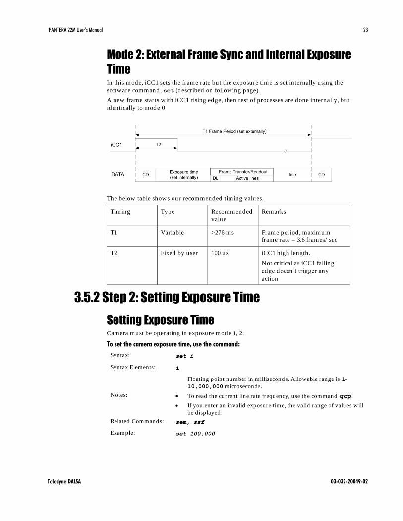
Mode 2: External Frame Sync and Internal Exposure
Time In this mode, iCC1 sets the frame rate but the exposure time is set internally using the
software command, set (described on following page).
A new frame starts with iCC1 rising edge, then rest of processes are done internally, but
identically to mode 0
The below table shows our recommended timing values,
Timing Type Recommended
value
Remarks
T1 Variable >276 ms Frame period , maximum
frame rate = 3.6 frames/ sec
T2 Fixed by user 100 us iCC1 high length.
Not critical as iCC1 falling
edge doesn’t trigger any
action
3.5.2 Step 2: Setting Exposure Time
Setting Exposure Time Camera must be operating in exposure mode 1, 2.
To set the camera exposure time, use the command:
Syntax: set i
Syntax Elements: i
Floating point number in milliseconds. Allowable range is 1-
10,000,000 microseconds.
Notes: To read the current line rate frequency, use the command Tgcp T. T
If you enter an invalid exposure time, the valid range of values will
be d isplayed .
Related Commands: sem, ssf
Example: set 100,000

24 PANTERA 22M User’s Manual
Teledyne DALSA 03-032-20049-02
3.6 TDI Mode
In TDI mode, the following events take place:
Rising edge of iCC2 Line Sync pulse or internal counter is triggering beginning
of a new line
New line starts with vertical transfer of one line
Stop vertical transfer and start horizontal readout
Read out dummy pixels
Read out active lines. In parallel process data from active pixels. Enable LVAL
for active pixels data.
Overclock pixels, required for internal processing
Id le state, waiting for next line sync
Figure 2. TDI mode timing diagram
The below table shows our recommended timing values,
Timing Type Recommended
value
Remarks
T1 Typical 103us Line period , set externally or
internally
Equivalent to 9.71kHz line
rate
T2 Minimum 0.12-1 us iCC2 high length.
Not critical as iCC2 falling
edge doesn’t trigger any
action
T3 Typical 28.7 us Line Sync to LVAL start
T4 Typical 74.22 us LVAL, slightly delayed from
active pixels due to internal
data processing

PANTERA 22M User’s Manual 25
Teledyne DALSA 03-032-20049-02
T5 Variable 1 us Depending on line rate
If iCC2 (line sync) is running at higher rate than the maximum, the signal will be ignored .
When the camera operates in TDI mode, iCC3 is driven High and iCC1 value is ignored
(so iCC1 could be driven either LOW – recommended, or High).
The sensor is exposed all the time and the lines are read w ith the frequency of the iCC2.
The value of FVAL will be set to LOW.
Setting TDI Direction (scd) To set CCD scanning direction in TDI mode, use the command:
Syntax: scd i
Syntax Elements: i
0 Top to bottom
1 Bottom to top
Related Commands: tdi
Example: Scd 0
Setting Sync Mode (ssm) To set sync mode to internal or external in TDI mode, use the command:
Syntax: ssm i
Syntax Elements: i
0 Internal Line sync
1 External line sync
Related Commands: tdi
Example: ssm 1
3.7 Setting Sync Frequency (TDI and Area Mode) For both TDI and Area mode, to set the camera’s frame rate and line rate values, use the
command:
Syntax: ssf i i
Syntax Elements: i
1 Frame rate: 278 – 16383 milliseconds
2 Line rate: 2780 – 16383 counts of pixel clock
26 PANTERA 22M User’s Manual
Teledyne DALSA 03-032-20049-02
Notes: To read the current line rate frequency, use the command gcp.
If you enter an invalid frame rate or line rate, the valid range of
values will be d isplayed.
Related Commands: sem, ssm
Example: ssf 1 2780
3.8 Switching between Area and TDI mode
(TDI/Area Mode) 1. TDI mode to Area
It is safe to switch from TDI mode to Area mode.
2. Area mode to TDI mode
It is safe to switch during exposure time or id le time. If switched during frame
transfer, the readout of fu ll frame will be done first before the camera enters into TDI
mode.
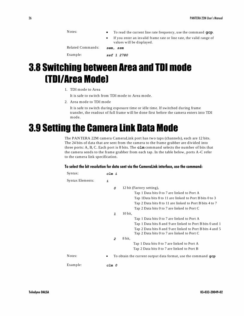
3.9 Setting the Camera Link Data Mode The PANTERA 22M camera CameraLink port has two taps (channels), each are 12 bits.
The 24 bits of data that are sent from the camera to the frame grabber are d ivided into
three ports: A, B, C. Each port is 8 bits. The clm command selects the number of bits that
the camera sends to the frame grabber from each tap. In the table below, ports A -C refer
to the camera link specification.
To select the bit resolution for data sent via the CameraLink interface, use the command:
Syntax: clm i
Syntax Elements: i
0 12 bit (Factory setting),
Tap 1 Data bits 0 to 7 are linked to Port A
Tap 1Data bits 8 to 11 are linked to Port B bits 0 to 3
Tap 2 Data bits 8 to 11 are linked to Port B bits 4 to 7
Tap 2 Data bits 0 to 7 are linked to Port C
1 10 bit,
Tap 1 Data bits 0 to 7 are linked to Port A
Tap 1 Data bits 8 and 9 are linked to Port B bits 0 and 1
Tap 2 Data bits 8 and 9 are linked to Port B bits 4 and 5
Tap 2 Data bits 0 to 7 are linked to Port C
2 8 bit,
Tap 1 Data bits 0 to 7 are linked to Port A
Tap 2 Data bits 0 to 7 are linked to Port B
Notes: To obtain the current output d ata format, use the command gcp
Example: clm 0
PANTERA 22M User’s Manual 27
Teledyne DALSA 03-032-20049-02
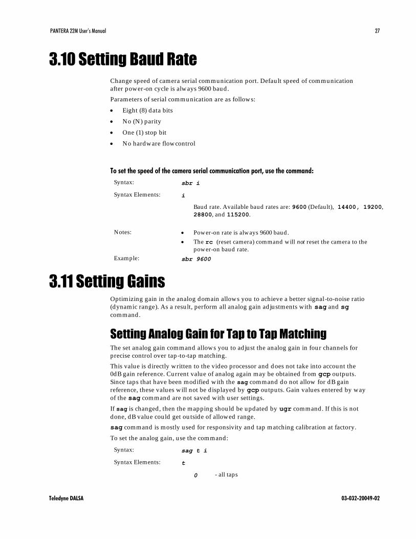
3.10 Setting Baud Rate Change speed of camera serial communication port. Default speed of communication
after power-on cycle is always 9600 baud.
Parameters of serial communication are as follows:
Eight (8) data bits
No (N) parity
One (1) stop bit
No hardware flowcontrol
To set the speed of the camera serial communication port, use the command:
Syntax: sbr i
Syntax Elements: i
Baud rate. Available baud rates are: 9600 (Default), 14400, 19200,
28800, and 115200.
Notes: Power-on rate is always 9600 baud .
The rc (reset camera) command will not reset the camera to the
power-on baud rate.
Example: sbr 9600
3.11 Setting Gains Optimizing gain in the analog domain allows you to achieve a better signal-to-noise ratio
(dynamic range). As a result, perform all analog gain ad justments with sag and sg
command.
Setting Analog Gain for Tap to Tap Matching The set analog gain command allows you to ad just the analog gain in four channels for
precise control over tap -to-tap matching.
This value is d irectly written to the video processor and does not take into account the
0dB gain reference. Current value of analog again may be obtained fr om gcp outputs.
Since taps that have been modified with the sag command do not allow for dB gain
reference, these values will not be d isplayed by gcp outputs. Gain values entered by way
of the sag command are not saved with user settings.
If sag is changed, then the mapping should be updated by ugr command. If this is not
done, dB value could get ou tside of allowed range.
sag command is mostly used for responsivity and tap matching calibration at factory.
To set the analog gain, use the command:
Syntax: sag t i
Syntax Elements: t
0 - all taps

28 PANTERA 22M User’s Manual
Teledyne DALSA 03-032-20049-02
1-4 - Tap count (select single tap)
i
0-1023. 0 corresponds to low gain, 1023 corresponds to high gain
Related Commands: gag ; ugr
Example: sag 0 27
Update Gain Reference Command ugr is to update 0dB gain reference to be equal to the current value of analog
gain setting. It is the DN value currently set to the video processor’s gain registers that is
used as the gain reference. As such, values entered via the sag command) as well as the
sg command are equally applicable. Gain references are saved with user settings.
Syntax: ugr
Set Gain (sg) Command sg is for setting analog gain in the video processor. The value written to the
video processor is summed with the 0dB gain reference. Current value of analog gain
may be obtained from gcp, and gag outputs. Gain settings entered by way of the sg
command are saved with user settings. If just higher responsivity is needed on all taps,
the easiest way is to send a command sg 0 x.
To set the analog gain, use the command:
Syntax: sg t i
Syntax Elements: t
0 - all taps
1-4 - Tap count (select single tap)
i
0.0 – 24.0 in dB, 0 corresponds to low gain, 24 corresponds to high
gain
Related Commands: gag ; gcp
Example: Sg 0 0

PANTERA 22M User’s Manual 29
Teledyne DALSA 03-032-20049-02
3.12 Monitoring the Camera The camera is equipped with a red/ green LED used to d isplay the operational status of
the camera. Table 6 below summarizes the operating states of the camera and the
corresponding LED states.
Table 6: Camera Operating States
LED state Priority Camera Status Condition
Blinking RED 1 Error Fatal hardware failure
Steady RED 2 Warning Monitoring task failure
Blinking
GREEN
3 Progress Lengthy operation in progress
Steady GREEN 4 OK Healthy
3.13 Rebooting the Camera The command rc reboots the camera. The camera starts up with the last saved settings.
3.14 Setting the Video Mode and Generating
Test Patterns
To set the video mode, use the command:
Syntax: tps i
Syntax Elements: i
0 video
1 Test pattern 1
2 Test pattern 2
Example: tps 0
Note: When more than
one condition is active,
the LED indicates the
condition with the
highest priority. Error
and warning states are
accompanied by
corresponding messages
further describing the
current camera status.

30 PANTERA 22M User’s Manual
Teledyne DALSA 03-032-20049-02

PANTERA 22M User’s Manual 31
Teledyne DALSA 03-032-20049-02
4 Optical and Mechanical
Considerations
4.1 Mechanical Interface Figure 6: Mechanical Drawing

32 PANTERA 22M User’s Manual
Teledyne DALSA 03-032-20049-02
4.2 Mounting the Camera The PANTERA 22Mcameras can be mounted via the 4 holes.
4.3 Thermal Management For any CCD camera optimal performance is achieved by transferring heat away from the
sensor. Keeping a sensor ―cool‖ red uces the amount of dark current generated . Dark
current is the leading contributor to FPN, PRNU, dark offset, random noise and other
performance specifications, especially when a camera is significantly gained (i.e. +10db).
PANTERA 22M mechanicals have been optimized to transfer heat from the sensor to the
front of the housing. Recommend to mount camera on a metal plate. Mount fans away
from the camera to avoid vibration, and d irect the airflow across the housing to decrease
the temperature delta between ambient and housing temperatures. Proper installation
greatly reduces dark current and will improve you systems performance.
4.4 Environment The camera and cables should be shielded from environmental noise sources for best
operation. The camera should also be kept as cool as possible. The specified operating
temperature is -10–50°C measured at the front surface of the camera.

PANTERA 22M User’s Manual 33
Teledyne DALSA 03-032-20049-02
5 Cleaning and
Maintenance
5.1 Cleaning
Electrostatic Discharge and the CCD Sensor Charge-coupled device (CCD) image sensors are metal oxide semiconductor (MOS)
devices and are susceptible to damage from electrostatic d ischarge (ESD). Although many
sensor pins have ESD protection circuitry, the ESD protection circuitry in CCDs is
typically not as effective as those found in standard CMOS circuits.
Electrostatic charge introduced to the sensor window surface can induce charge buildup
on the underside of the window that cannot be read ily d issipated by the dry nitrogen gas
in the sensor package cavity. When charge buildup occurs, surface gated photodiodes
(SGPDs) may exhibit higher image lag. Some SGPD sensors may also exhibit a highly
non-uniform response when affected by charge build -up, with some pixels d isplaying a
much higher response when the sensor is exposed to uniform illumination. The charge
normally d issipates within 24 hours and the sensor returns to normal operation.
Preventing ESD Damage To prevent ESD damage, we advise you to take the following handling precautions.
1. Ground yourself prior to handling CCDs.
2. Ensure that your ground and your workbench are also properly grounded. Install
conductive mats if your ground or workbench is non -conductive.
3. Use bare hands or non-chargeable cotton gloves to handle CCDs. NOTE: Rubber
fingercots can introduce electrostatic charge if the rubber comes in contact with the
sensor window.
4. Do not touch the window, especially in the region over the imaging are a.
5. Ground all tools and mechanical components that come in contact with the CCD.
6. We recommend that CCDs be handled under ionized air to prevent static charge
buildup.
The above ESD precautions need to be followed at all times, even when there is no
evidence of CCD damage. The rate which electrostatic charge d issipates depends on
numerous environmental conditions and an improper handling procedure that does

34 PANTERA 22M User’s Manual
Teledyne DALSA 03-032-20049-02
not appear to be damaging the CCDs immediately may cause damage with a change
in environmental conditions.
Protecting Against Dust, Oil, and Scratches The CCD window is part of the optical path and should be handled like other optical
components, with extreme care.
Dust can obscure pixels, producing dark patches on the sensor response. Dust is most
visible when the illumination is collimated . The dark patches shift position as the angle of
illumination changes. Dust is normally not visible when the sensor is positioned at the
exit port of an integrating sphere, where the illumination is d iffuse.
Dust can normally be removed by blowing the window surface using an ionized air gun.
Oil is usually introduced during handling. Touching the surface of the window
barehanded will leave oily residues. Using rubber fingercots and rubber gloves can
prevent contamination. However, the friction between rubber and the window may
produce electrostatic charge that may damage the sensor. To avoid ESD damage and to
avoid introducing oily residues, avoid touching the sensor.
Scratches d iffract incident illumination. When exposed to uniform illumination, a sensor
with a scratched window will normally have brighter p ixels ad jacent to darker pixels. The
location of these pixels will change with the angle of illumination.
Cleaning the Sensor Window
Equipment Required
Glass cleaning station with microscope within clean room.
3M ionized air gun 980
(http:/ / solu tions.3mcanada.ca/ wps/ portal/ 3M/ en_CA/ WW2/ Country/ )
Ionized air flood system, foot operated .
Swab (HUBY-340CA-003)
(http:/ / www.cleancross.net/ modules/ xfsection/ article.php?articleid=24)
Single drop bottle (FD-2-ESD)
E2 (Eclipse optic cleaning system (www.photosol.com )
Procedure
Use localized ionized air flow on to the glass during sensor cleaning.
Blow off mobile contamination using an ionized air gun.
Place the sensor under the microscope at a magnification of 5x to determine the
location of any remaining contamination.
Clean the contamination on the sensor using one drop of E2 on a swab.
Wipe the swab from left to right ( or right to left but only in one d irection). Do this in
an overlapping pattern, turning the swab after the first wipe and with each
subsequent wipe. Avoid swiping back and forth with the same swab in order to
ensure that particles are removed and not simply transferred to a new location on the
sensor window. This procedure requires you to use multiple swabs.
Discard the swab after both sides of the swab have been used once.
Repeat until there is no visible contamination present.

PANTERA 22M User’s Manual 35
Teledyne DALSA 03-032-20049-02
5.2 Maintenance There are no user serviceable parts on this camera. Please contact Teledyne DALSA for service.

36 PANTERA 22M User’s Manual
Teledyne DALSA 03-032-20049-02

PANTERA 22M User’s Manual 37
Teledyne DALSA 03-032-20049-02
6 Troubleshooting
The information in this chapter can help you solve problems that may occur during the
setup of your camera. Remember that the camera is part of the entire acquisition system.
You may have to troubleshoot any or all of the following:
power supplies cabling
frame grabber hardware & software host computer
light sources optics
operating environment encoder
Your steps in dealing with a technical problem should be:
1. Try the general and specific solu tions listed in sections 6.1, 6.2, and 6.3.
2. If these solu tions do not resolve your problem, see section 6.4 on getting product
support.
6.1 Common Solutions
Connections The first step in troubleshooting is to verify that your camera has all the correct
connections.
Power Supply Voltages Check for the presence of all voltages at the camera power connector. Verify that all
grounds are connected .
EXSYNC When the camera is powered on for the first time, the factory setting is default(no external
inputs required ). After you have saved settings, the camera powers up with the saved
settings next time it is rebooted .
Data Clocking/Output Signals To validate cable integrity, have the camera send out a test pattern and verify it is being
properly received.

38 PANTERA 22M User’s Manual
Teledyne DALSA 03-032-20049-02
6.2 Troubleshooting Using the Serial Interface The following commands can aid in debugging. (The complete command protocol is
described in Appendix B.)
Communications To quickly verify serial communications send the help command. The h command
returns the online help menu.
Verify Parameters To verify the camera setup, send the gcp command.
Verify Factory Calibrated Settings To restore the camera’s factory settings, send the rfs command.
After executing this command send the gcp command to verify the factory settings.
Verify Timing and Digital Video Path Use the test pattern feature to verify the proper timing and connections between the
camera and the frame grabber and verify the proper output along the d igital processing
chain. See below.
Generating Test Patterns The camera can generate a test pattern to aid in system debugging. Use the command
svm i to activate the test pattern (see section 3.14 Setting the Video Mode and
Generating Test Patterns for details). The test pattern is a ramp from 1 to the number of
pixels in the line, then starts at 1 again. Use the test pattern to verify the proper timing
and connections between the camera and the frame grabber.
No test pattern or bad test pattern — May indicate a problem with the camera (e.g.
missing bit) or a system setup problem (e.g. frame grabber or timing). Verify the
presence of the LVAL and STROBE signals.
Test pattern successful — Run the svm 0 command to deactivate video correction.
Verify Temperature To check the camera’s internal temperature, use the vt command. If it is within the
proper range, the camera returns OK>. Otherwise the camera returns an error message.
LED Status Located on the back of the camera is a red/ green LED used to d isplay the operational
status of the camera. Red lights indicate errors or warnings and green lights indicate
progress and OKs. Error and warning states are accompanied by correspond ing messages
further describing current camera status. See section 2.2.1 LED Status Indicator for the
complete LED information.

PANTERA 22M User’s Manual 39
Teledyne DALSA 03-032-20049-02
6.3 Specific Solutions
No Output or Erratic Behavior If your camera provides no output or behaves erratically, it may be picking up random
noise from long cables acting as antennae. Do not attach wires to unused pins. Verify that
the camera is not receiving spurious inputs (e.g. EXSYNC, if camera is in exposure mode
that regulates external signals).
Line Dropout, Bright Lines, or Incorrect Frame Rate Verify that the frequency of the internal sync is set correctly, or when the camera is set to
external sync that the EXSYNC signal supplied to the camera does not exceed the
camera’s maximum specified frame rate.
Noisy Output Check your power supply voltage outputs for noise. Noise present on these lines can
result in poor video quality. Low quality or non -twisted pair cable can also add noise to
the video output.
Dark Patches If dark patches appear in your output the optics path may have become contaminated .
Refer to the sensor cleaning procedure in Chapter 5. for proper cleaning instructions.
Horizontal Lines or Patterns in Image A faulty or irregular encoder signal may result in horizontal lines due to exposure time
fluctuations; ensure that your exposure time is regular. If you have verified that your
exposure time is consistent and patterns of low frequency intensity variations still occur,
ensure that you are using a DC or high frequency light source.
40 PANTERA 22M User’s Manual
Teledyne DALSA 03-032-20049-02
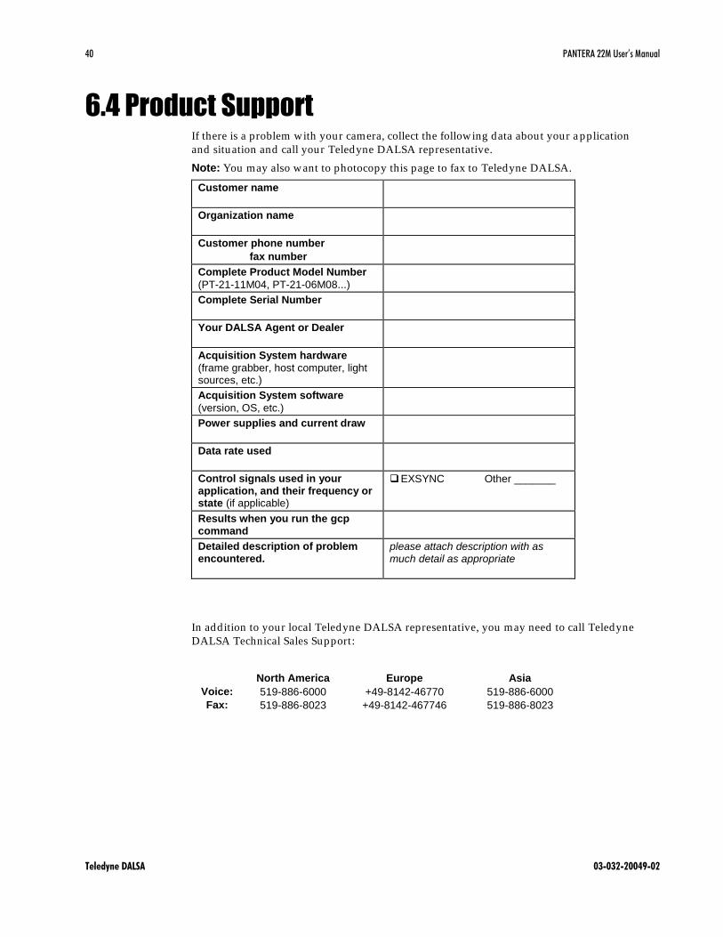
6.4 Product Support If there is a problem with your camera, collect the following data about your a pplication
and situation and call your Teledyne DALSA representative.
Note: You may also want to photocopy this page to fax to Teledyne DALSA.
Customer name
Organization name
Customer phone number
fax number
Complete Product Model Number
(PT-21-11M04, PT-21-06M08...)
Complete Serial Number
Your DALSA Agent or Dealer
Acquisition System hardware
(frame grabber, host computer, light sources, etc.)
Acquisition System software
(version, OS, etc.)
Power supplies and current draw
Data rate used
Control signals used in your application, and their frequency or state (if applicable)
EXSYNC Other _______
Results when you run the gcp command
Detailed description of problem encountered.
please attach description with as much detail as appropriate
In addition to your local Teledyne DALSA representative, you may need to call Teledyne
DALSA Technical Sales Support:
Voice:
Fax:
North America
519-886-6000
519-886-8023
Europe
+49-8142-46770
+49-8142-467746
Asia
519-886-6000
519-886-8023

PANTERA 22M User’s Manual 41
Teledyne DALSA 03-032-20049-02
Appendix A
Camera Link™ Reference,
Configuration and Image
Construction
Camera Link is a communication interface for vision applications. It provides a
connectivity standard between cameras and frame grabbers.
LVDS Technical Description Low Voltage Differential Signaling (LVDS) is a high-speed, low -power general-purpose
interface standard . The standard , known as ANSI/ TIA/ EIA-644, was approved in March
1996. LVDS uses d ifferential signaling, with a nominal signal swing of 350mV differential.
The low signal swing decreases rise and fall times to achieve a theoretical maximum
transmission rate of 1.923 Gbps into a loss-less medium. The low signal swing also means
that the standard is not dependent on a particular supply voltage. LVDS uses current-
mode drivers, which limit power consumption. The d ifferential signals are immune to ±1
V common volt noise.
Camera Signal Requirements This section provides definitions for the signals used in the Camera Link interface. The
standard Camera Link cable provides camera control signals, serial communication, and
video data.
Video Data The Channel Link technology is integral to the transmission of video data. Image data
and image enable signals are transmitted on the Channel Link bus. Four enable signals
are defined as:
• FVAL—Frame Valid (FVAL) is defined HIGH for valid lines.
• LVAL—Line Valid (LVAL) is defined HIGH for valid p ixels.
• DVAL—Data Valid (DVAL) is d efined HIGH when data is valid .
• Spare— A spare has been defined for fu ture use.
All four enable signals must be provided by the camera on each Channel Link chip. All
unused data bits must be tied to a known value by the camera. For more info rmation on
image data bit allocations, refer to the official Camera Link Road Map specification on the
www.teledynedalsa.com Web site.

42 PANTERA 22M User’s Manual
Teledyne DALSA 03-032-20049-02
Camera Control Signals Four LVDS pairs are reserved for general-purpose camera control. They are defined as
camera inputs and frame grabber outputs. Camera manufacturers can define these signals
to meet their needs for a particular product. The signals are:
• Camera Control 1 (CC1)
• Camera Control 2 (CC2)
• Camera Control 3 (CC3)
• Camera Control 4 (CC4)
Communication Two LVDS pairs have been allocated for asynchronous serial communication to and from
the camera and frame grabber. Cameras and frame grabbers should support at least 9600
baud. These signals are
• SerTFG—Differential pair with serial communications to the frame grabber.
• SerTC—Differential pair w ith serial communications to the camera.
The serial interface will have the following characteristics: one start bit, one stop bit, no
parity, and no handshaking. It is recommended that frame grabber manufacturers supply
both a user interface and a software application programming interface (API) for using
the asynchronous serial communication port. The user interface will consist of a terminal
program with minimal capabilities of sending and receiving a character string and
sending a file of bytes. The software API will provide functions to enumerate boards and
send or receive a character string. See Ap pendix B in the Official Camera Link
specification on the Web site
(http:/ / www.teledynedalsa.com/ mv/ knowledge/ appnotes.aspx).
Power Power will not be provided on the Camera Link connector. The camera will receive
power through a separate cable. Camera manufacturers will define their own power
connector, current, and voltage requirements.
Camera Link™ Configuration Table The following table provides tap reconstruction information. DALSA is working with the
machine vision industry to use this table as the basis for auto configuration. Visit the H
Web site and view the DALSA Camera Link Implementation Road Map document for
further details (http:/ / www.teledynedalsa.com/ mv/ knowledge/ appnotes.aspx).
PANTERA 22M User’s Manual 43
Teledyne DALSA 03-032-20049-02
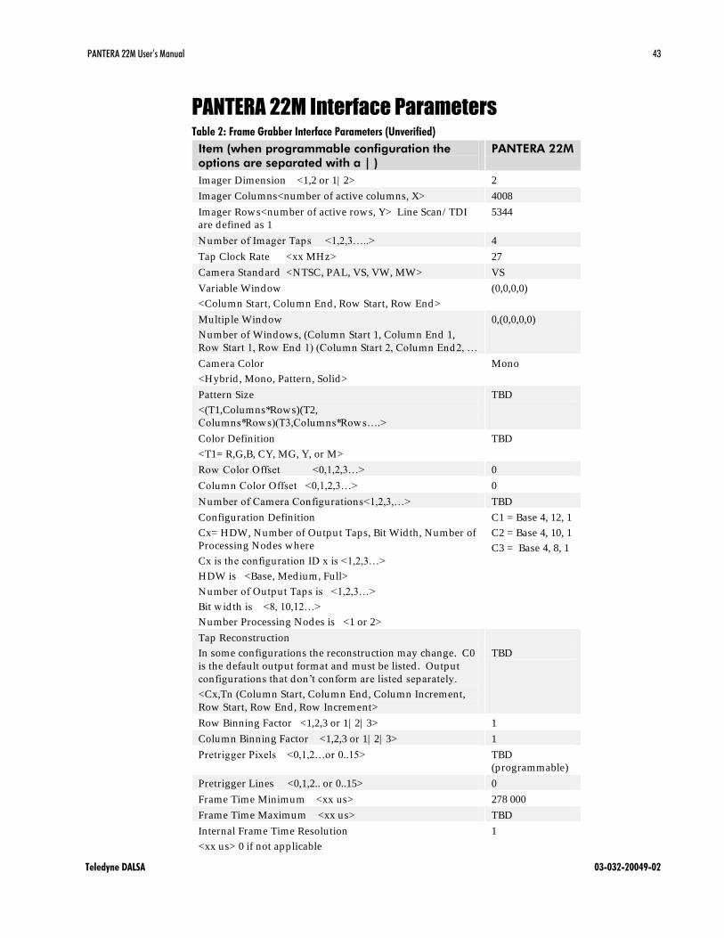
PANTERA 22M Interface Parameters Table 2: Frame Grabber Interface Parameters (Unverified)
Item (when programmable configuration the
options are separated with a | )
PANTERA 22M
Imager Dimension <1,2 or 1| 2> 2
Imager Columns<number of active columns, X> 4008
Imager Rows<number of active rows, Y> Line Scan/ TDI
are defined as 1
5344
Number of Imager Taps <1,2,3…..> 4
Tap Clock Rate <xx MHz> 27
Camera Standard <NTSC, PAL, VS, VW, MW> VS
Variable Window
<Column Start, Column End, Row Start, Row End>
(0,0,0,0)
Multiple Window
Number of Windows, (Column Start 1, Column End 1,
Row Start 1, Row End 1) (Column Start 2, Column End2, …
0,(0,0,0,0)
Camera Color
<Hybrid , Mono, Pattern, Solid>
Mono
Pattern Size
<(T1,Columns*Rows)(T2,
Columns*Rows)(T3,Columns*Rows….>
TBD
Color Definition
<T1= R,G,B, CY, MG, Y, or M>
TBD
Row Color Offset <0,1,2,3…> 0
Column Color Offset <0,1,2,3…> 0
Number of Camera Configurations<1,2,3,…> TBD
Configuration Definition
Cx= HDW, Number of Output Taps, Bit Width, Number of
Processing Nodes where
Cx is the configuration ID x is <1,2,3…>
HDW is <Base, Medium, Full>
Number of Output Taps is <1,2,3…>
Bit wid th is <8, 10,12…>
Number Processing Nodes is <1 or 2>
C1 = Base 4, 12, 1
C2 = Base 4, 10, 1
C3 = Base 4, 8, 1
Tap Reconstruction
In some configurations the reconstruction may change. C0
is the default output format and must be listed . Output
configurations that don’t conform are listed separately.
<Cx,Tn (Column Start, Column End, Column Increment,
Row Start, Row End, Row Increment>
TBD
Row Binning Factor <1,2,3 or 1| 2| 3> 1
Column Binning Factor <1,2,3 or 1| 2| 3> 1
Pretrigger Pixels <0,1,2…or 0..15> TBD
(programmable)
Pretrigger Lines <0,1,2.. or 0..15> 0
Frame Time Minimum <xx us> 278 000
Frame Time Maximum <xx us> TBD
Internal Frame Time Resolution
<xx us> 0 if not applicable
1

44 PANTERA 22M User’s Manual
Teledyne DALSA 03-032-20049-02
Item (when programmable configuration the
options are separated with a | )
PANTERA 22M
Pixel Reset Pulse Minimum Width
<xx ns> 0 if not applicable
0
Internal Pixel Reset Time Resolution
<xx ns> 0 if not applicable
0
Pixel Reset to Exsync Hold time <xx ns> TBD
BAUD Rate <9600….> 9600
CC1 <Area mode> Smart Exsync
CC2 <TDI mode> Line Sync
CC3 <Area/ TDI mode > Selectable
CC4 <Spare> Spare
DVAL out <Strobe Valid , Alternate> Data Valid , held
high except in
binning modes
FVAL out <Frame Valid , Alternate> Frame Valid
LVAL< Frame Valid , Alternate > Line Valid
PANTERA 22M Image Construction
Table: Data channels configuration
22M03 tap Data channel#, default configuration
Data channel#, custom configuration(for use with
Xcellera PX-4 framegrabber)
W 1 1
X 3 2
Z 2 3
Y 4 4

PANTERA 22M User’s Manual 45
Teledyne DALSA 03-032-20049-02
Appendix B
Commands and Error Handling
This table provides a brief overview of all of the available user commands. For a detailed
explanation of these commands, refer to Chapter 3.
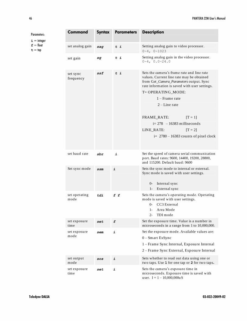
Table: All Available CommandsTable 3Table 4
Command
Syntax Parameters Description
FPGA
configuration
store
fcs Place the camera into FPGA code download
state. Use HyperTerminal application to
download the binary image of the FPGA
configuration the file, the camera needs to be
reset or power cycled.
Before starting the download process with
this commend, the camera’s serial data rate
should be increased by using the sbr. A
baud rate of 115200 is recommended .
get analog gain gag Read the camera analog gain
get analog
offset gao Read the camera analog offset
get camera
model gcm Read the camera model number
get camera
parameters gcp Read all of the camera parameters.
get camera
serial gcs Read the camera serial number
get camera
version gcv Read the firmware version and FPGA version
get sensor
serial gss Read the sensor serial number
help h Display the online help
camera link
mode clm i Sets the data mode to use. Available values
are:
0: 12 bit mode
1: 10 bit mode
2: 8 bit mode
reset camera rc Reset the entire camera (reboot)
restore factory
settings rfs Restore the camera’s factory settings.
restore user
settings rus Restore the camera's last saved user settings.
Parameters:
i = integer
f = float
t = tap
46 PANTERA 22M User’s Manual
Teledyne DALSA 03-032-20049-02
Command
Syntax Parameters Description
set analog gain sag t i Setting analog gain to video processor.
0~4, 0~1023
set gain sg t i Setting analog gain in the video processor. 0~4, 0.0~24.0
set sync
frequency
ssf t i Sets the camera’s frame rate and line rate
values. Current line rate may be obtained
from Get_Camera_Parameters output. Sync
rate information is saved with user settings.
T= OPERATING_MODE:
1 – Frame rate
2 – Line rate
FRAME_RATE: [T = 1]
i= 278 – 16383 milliseconds
LINE_RATE: [T = 2]
i= 2780 – 16383 counts of pixel clock
set baud rate sbr i Set the speed of camera serial communication
port. Baud rates: 9600, 14400, 19200, 28800,
and 115200. Default baud: 9600
Set sync mode ssm i Sets the sync mode to internal or external.
Sync mode is saved with user settings.
0- Internal sync
1- External sync
set operating
mode tdi f f Sets the camera’s operating mode. Operating
mode is saved with user settings.
0- CC3 External
1- Area Mode
2- TDI mode
set exposure
time set f Set the exposure time. Value is a number in
microseconds in a range from 1 to 10,000,000.
set exposure
mode sem i Set the exposure mode. Available values are:
0 – Smart ExSync
1 – Frame Sync Internal, Exposure Internal
2 – Frame Sync External, Exposure Internal
set output
mode sos i Sets whether to read out data using one or
two taps. Use 1 for one tap or 2 for two taps.
set exposure
time set i Sets the camera’s exposure time in
microseconds. Exposure time is saved with
user. I = 1 – 10,000,000uS
Parameters:
i = integer
f = float
t = tap

PANTERA 22M User’s Manual 47
Teledyne DALSA 03-032-20049-02
Command
Syntax Parameters Description
set td i
d irection scd i Set video mode. Available values are:
0: Top to Bottom
1: Bottom to Top
Test pattern
select tps Selects between video output, test pattern 1,
and test pattern 2 output. Test pattern mode
is saved with user settings.
TEST_PATTERN:
0 – video
1 – test pattern 1
2 – test pattern 2
write user
settings wus Write all of the user settings to EEPROM
update gain
reference ugr Updates 0dB gain reference to be equal to the
current value of analog gain setting. It is the
DN value currently set to the video
processor’s gain registers that is used as the
gain reference. As such, values entered via
the sag command (Set_Analog_Gain) as well
as the sg command (Set_Gain) are equally
applicable. Gain references are saved with
user settings.
verify voltage vv Measures and reports the external voltage
supply provided to the camera.
Parameters:
i = integer
f = float
t = tap

48 PANTERA 22M User’s Manual
Teledyne DALSA 03-032-20049-02

PANTERA 22M User’s Manual 49
Teledyne DALSA 03-032-20049-02
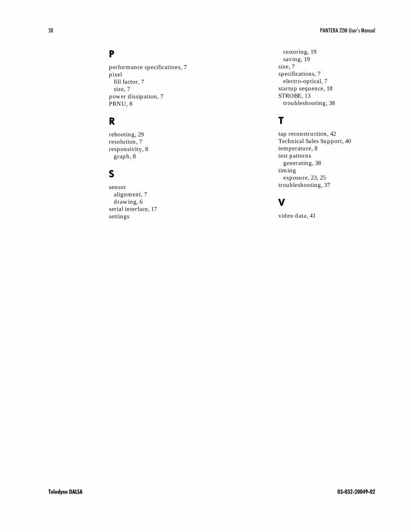
Index
2
2 taps, 19, 20
A
aperture, 7
applications, 6
B
baud rate, 27
bright lines, 39
C
camera control signals, 42
Camera Link
configuration, 13, 14
connector, 13
signals, 13
clock signals, 13
commands
descriptions, 45
connector
Camera Link, 12
data, 12
pinout, 12
power, 14
D
dark patches, 39
data bus, 13
data rate, 7
d igital data, 13
DVAL, 13, 41
dynamic range, 8
E
EMC Declaration of
Conformity, 42
exposure
control, 19
modes, 19
setting, 20
time, 19
exposure time
setting, 23, 25
EXSYNC, 14
troubleshooting, 37
external trigger, 14
F
features, 5
fill factor, 7
frame rate, 7
FVAL, 41
G
gain range, 8
H
help, 17
I
incorrect line rate, 39
installation, 11
interface parameters, 43
L
LED, 12
line dropout, 39
LVAL, 13, 41
LVDS, 41
pairs, 42
M
MDR26 connector, 11, 13
modes, 20
exposure, 20
operating, 20
N
noisy output, 39
O
operating modes, 20
operating temp, 8
50 PANTERA 22M User’s Manual
Teledyne DALSA 03-032-20049-02
P
performance specifications, 7
pixel
fill factor, 7
size, 7
power d issipation, 7
PRNU, 8
R
rebooting, 29
resolution, 7
responsivity, 8
graph, 8
S
sensor
alignment, 7
d rawing, 6
serial interface, 17
settings
restoring, 19
saving, 19
size, 7
specifications, 7
electro-optical, 7
startup sequence, 18
STROBE, 13
troubleshooting, 38
T
tap reconstruction, 42
Technical Sales Support, 40
temperature, 8
test patterns
generating, 38
timing
exposure, 23, 25
troubleshooting, 37
V
video data, 41

Revision History
DATE Revision Action Originator
23/ 05/ 2008 00 Initial Release Lawson Luo
19/ 11/ 2009 01 See detail below Lawson Luo
08/ 19/ 2011 02 -Update to cosmetic
blemish and sensor
cleaning procedure
-Restored missing
labels to timing
d iagrams.
Gary Gagne
Details of the changes at version 01:
1. On page 26 in the second to last sentence it says "there values will not be d isp layed by gcp outputs"
has been corrected to "these values"
2. On page 27 it says "d igital gain" has been changed to "analog gain"
3. On page 26 the sentence that says "Current value of analog again may be obtained from gcp outputs."
Has been changed to "Current value of analog gain may be obtained from gcp outputs."
4. Cover picture has been updated .
5. On pa25, section 3.9, setting the camera link data mod, line 1, ―the PANTERA 22M camera have four
tapes, each are 12 bits‖ ―The PANTERA 22M camera CameraLink port has two taps (channels), each
are 12 bits.
6. On page 25, section 3.9, ―The 28 bits of data that are sent from the camera to the frame grabber are
divided into three ports: A, B, C. Each port is 8 bits.‖ Has been changed to ―The 24 bits of data that are
sent from the camera to the frame grabber are d ivided into three ports: A, B, C. Each po rt is 8 bits.‖
7. On page 26-27, definitions of ugr and sg have been added into chapter 3.11 setting analog gain.
8. On page 39 and 40. the website address ―heep:/ / vfm.dalsa.com‖ has been changed to
―www.dalsa.com‖
9. On page 42, the Table: Data channels configuration has been updated .
10. On page 44, the description of the command sag and sg of have been updated .
11. Footer has been updated with the reflection of version 01.
12. Picture on the front page has been updated .