1charging wireless sensor networks with mobile charger and
TRANSCRIPT
1Charging Wireless Sensor Networks with Mobile Charger
and Infrastructure Pivot Cluster Heads
Dongsoo Har
Abstract
Wireless rechargeable sensor networks (WRSNs) consisting of sensor nodes with batteries
have been at the forefront of sensing and communication technologies in the last few years. Sensor
networks with different missions are being massively rolled out, particularly in the internet-of-
things commercial market. To ensure sustainable operation of WRSNs, charging in a timely fashion
is very important, since lack of energy of even a single sensor node could result in serious outcomes.
With the large number of WRSNs existing and to be existed, energy-efficient charging schemes are
becoming indispensable to workplaces that demand a proper level of operating cost. Selection of
charging scheme depends on network parameters such as the distribution pattern of sensor nodes,
the mobility of the charger, and the availability of the directional antenna. Among current charging
techniques, radio frequency (RF) remote charging with a small transmit antenna is gaining interest
when non-contact type charging is required for sensor nodes. RF charging is particularly useful
when sensor nodes are distributed in the service area. To obtain higher charging efficiency with RF
charging, optimal path planning for mobile chargers, and the beamforming technique,
implemented by making use of a directional antenna, can be considered. In this article, we present a
review of RF charging for WRSNs from the perspectives of charging by mobile charger, harvesting
using sensor nodes, and energy trading between sensor nodes. The concept of a pivot cluster head is
introduced and a novel RF charging scheme in two stages, consisting of charging pivot cluster
heads by a mobile charger with a directional antenna and charging member sensor nodes by pivot
cluster heads with directional antennae, is presented.
I. INTRODUCTION
Dongsoo Har is with the Cho Chun Shik Graduate School of Green Transportation, KAIST, 291 Daehak-ro, Daejeon, Republic of
Korea.
E-mail: [email protected] (Dongsoo Har).

The Internet of things (IoT) is creating a new paradigm in regards to the connectivity and
intelligence of various types of sensor devices. Advancements in microchip fabrication technology have
led to widespread adoption of sensor devices, such as radio frequency identification (RFID) tags, and
extensive deployment of wireless sensor networks. Wireless sensor networks, which treat sensor devices
as network nodes, serve as critical enablers of the IoT [1], carrying out missions of monitoring,
localization, tracking of objects by seamless transfer of data in real time between sensor nodes [2]. Since
sustainable operation of wireless sensor networks is a major concern, particularly with mission-critical
sensor networks, the importance of charging the sensor nodes in a timely manner cannot be
overemphasized. Devices operated with batteries usually have short lifetimes and most wireless sensor
networks cease their operation when even a single or small number of sensor nodes become energy-
depleted. Therefore, one of the primary objectives considered when designing a wireless rechargeable
sensor network (WRSN) consisting of sensor nodes with batteries is to prolong the network lifetime
without compromising the sensing performance [3]. From this viewpoint, it is necessary to develop a
charging scheme for WRSNs that does not jeopardize the quality of service of the network operation.
Charging the WRSNs involves several issues. Charging method can be contact type near-field charging or
non-contact type far-field charging. Contact type near-field charging is typically based on magnetic
induction and low frequency in the HF band. Charging efficiency of this method is very low when the
sensor node is located more than a meter from the charger. Charger can be an infrastructure charger or a
mobile charger. An infrastructure charger or immobile charger is not suitable for WRSNs deployed in
large service areas where the sensor nodes are distributed. Charging efficiency with mobile chargers is
higher because energy transfer to individual sensor nodes suffers less wave propagation loss with small
distances between the charger and the sensor nodes. The configuration of the WRSN depends on the
number of sensor nodes and the type of node localization. When many sensor nodes, on the order of
hundred, are distributed in a large service area, charging efficiency significantly varies according to the
specific charging scheme. Sensor nodes of WRSNs must have energy harvesting capability. Energy
harvesting circuits have different configurations depending on the type of energy source. When that
source is ambient radio frequency (RF) energy from a TV signal, cellular signal, or Wi-Fi signal, the
amount of harvested energy is typically very low. On the other hand, when it is RF energy transferred by
an intended charger, the amount of harvested energy is much larger. RF (energy) charging is gaining
interest because of the use of small transmit and receive antennae for energy transmission and reception.
In addition, the beamforming technique, which can provide high directional gain for antennae, can
facilitate increased charging efficiency.
When a decent number of sensor nodes are involved in a WRSN deployed in a large service area,
RF charging with a mobile charger requires substantial charging time for all the sensor nodes to reach the

target energy level. Since this charging process is repeated regularly or irregularly according to
application of the WRSN, an energy-efficient charging scheme is indispensable to maintaining a proper
level of operating cost. In this article, an energy-efficient charging scheme is considered a charging
scheme with reduced charging time for a given transmit power of the charger. In order to achieve this
goal, optimized charging schemes for WRSNs aiming at finding optimal charging spots [4] and
establishing optimal velocity control [5] have recently appeared in the literature. However, with a large
number of sensor nodes to recharge, optimization for energy-efficient charging is accompanied by high
computational complexity, which grows non-linearly with increased number of sensor nodes. Therefore, a
sub-optimal charging scheme with reduced computational complexity might be more effective in practice.
To this end, a novel energy-efficient charging method in two stages with a mobile charger and pivot
cluster heads is presented here.
All the sensor nodes considered here are stationary or quasi-stationary sensor nodes. For energy-
efficient charging, the sensor nodes are classified into clusters. Each cluster consists of a cluster head and
member sensor nodes. When the cluster head has a directional antenna capable of steering beamforming
for transmitting energy, it is a pivot cluster head here. Other than the pivot cluster heads, the sensor nodes
have omni-directional antennae with 0dB antenna gain. The RF charging scheme in two stages is
composed of charging for pivot cluster heads in the first stage with a mobile charger and charging for
member sensor nodes by pivot cluster heads in the second stage. This charging scheme is hierarchical, in
contrast to other flat charging schemes. The mobile charger is only concerned with the pivot cluster heads,
so the computational complexity is substantially reduced. The pivot cluster heads are determined
according to a simple clustering algorithm and it is highly likely that pivot cluster heads will be located at
or around the center of locally grouped sensor nodes. Due to the natural wavefront spreading of
electromagnetic waves, member sensor nodes other than the pivot cluster heads are also charged in the
first stage with the mobile charger. When the first stage is complete, all the pivot cluster heads become
overcharged, i.e., charged more than the target level set for the pivot cluster heads, and member sensor
nodes are overcharged or partially charged. To complete the entire charging process for all the sensor
nodes, energy transfer from pivot cluster heads to member sensor nodes takes place until all the member
sensor nodes are charged over the target level set for the member sensor nodes. To achieve an energy-
efficient charging process, the target energy level of the pivot cluster heads and the target energy level of
the member sensor nodes are set at different values. Notably, antennae with directive gain are used for the
mobile charger and also the pivot cluster heads when these entities transfer energy. For a comparison
purpose, another charging scheme without costly directional antennae for cluster heads is also considered.
Main differences of this charging scheme are the target energy level of the cluster heads set differently

from that of the pivot cluster heads and energy trading between overcharged sensor nodes, including
cluster heads, and undercharged sensor nodes.
This article is organized as follows. The review of energy harvesting and RF charging with a
mobile charger is given in Section II. The process of energy-efficient charging in two stages with a
mobile charger and pivot cluster heads is presented in Section III. The conclusion of this article is
given in Section IV.
II. Energy Harvesting and RF Charging with Mobile Charger
A. Energy Harvesting with Different RF Sources
Wireless remote charging is seen as a powerful technology that can be used to power various
types of sensor devices with capabilities of energy harvesting. Figure 1 illustrates the types of energy
sources for energy harvesting. Solar energy can be captured by sensor nodes with small photovoltaic
panels installed on or around them. Thermal energy is harvested by making use of thermoelectric
converters converting heat energy into electric energy according to the Seebeck effect [6]. Harvesting
vibrational energy is enabled by piezoelectric sensors utilized as transducers. However, these types of
environmental energy are vulnerable to intermittency. Solar energy is accessible only during daytime and
under certain weather conditions; thermal energy is excessively scarce for energy demanding applications;
sources generating vibrational energy are rather limited. For these reasons, RF energy is emerging as the
major source to power sensor devices. Harvesting RF energy can be practiced with a battery, since most
components necessary for harvesting, such as antenna, rectifier, and amplifier, already exist in typical
sensor devices implemented in the form of customized ASICs or FPGAs [7, 8]. Harvesting ambient RF
energy can be classified into two different processes, according to the type of energy source, as follows:
Anticipated sources: RF sources that are always present, e.g., TV signals and radio signals, but
are not optimized nor specialized for the transmission of power to the sensor devices
Dynamic energy sources: RF sources that are periodic and unstable, usually transmitting in short
periods of time and requiring spectrum sensing by sensor devices for harvesting opportunities

On the other hand, harvesting RF energy with a dedicated RF charger is predictable with decent
accuracy, when the pathloss model to estimate the power received at sensor devices and the location
information of the sensor devices are commensurate with the desired accuracy. RF charging is expected to
deliver a steady influx of energy to the sensor devices as long as the charger keeps transferring. It can be
optimized in relation to charging frequency and the beamforming direction of the RF charger can be
adjusted to obtain the highest level of charging efficiency. RF charging can work with tens of meters of
distances between the transmitter and the sensor devices. Thus, RF charging can be applicable to operate
the sensor nodes in WRSNs. An example of a sensor device capable of RF energy harvesting is shown in
Fig. 2. The sensor device is seen to have a T-shaped directional antenna.
Fig. 1. Different types of sources for energy harvesting by sensor device.
Fig. 2. Sensor node capable of RF energy harvesting [9].
B. Energy Harvesting in Spectrum Sharing and Energy Trading
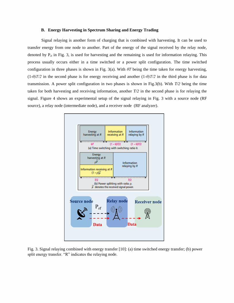
Signal relaying is another form of charging that is combined with harvesting. It can be used to
transfer energy from one node to another. Part of the energy of the signal received by the relay node,
denoted by Prf in Fig. 3, is used for harvesting and the remaining is used for information relaying. This
process usually occurs either in a time switched or a power split configuration. The time switched
configuration in three phases is shown in Fig. 3(a). With θT being the time taken for energy harvesting,
(1-θ)T/2 in the second phase is for energy receiving and another (1-θ)T/2 in the third phase is for data
transmission. A power split configuration in two phases is shown in Fig.3(b). With T/2 being the time
taken for both harvesting and receiving information, another T/2 in the second phase is for relaying the
signal. Figure 4 shows an experimental setup of the signal relaying in Fig. 3 with a source node (RF
source), a relay node (intermediate node), and a receiver node (RF analyzer).
Fig. 3. Signal relaying combined with energy transfer [10]: (a) time switched energy transfer; (b) power
split energy transfer. “R” indicates the relaying node.

Fig. 4. Signal relaying configuration [11].
Energy trading [12] between sensor nodes can greatly improve the charging efficiency of the
system by pluralizing the sources of energy in a WRSN. A charging scheme based on a single mobile
charger is likely to cause imbalances in energy intake of the sensor nodes. In a WRSN consisting of dense
sensor nodes, overcharged sensor nodes and undercharged sensor nodes can co-exist. Imbalances of
sensor nodes can be reduced by energy trading between sensor nodes. Overcharged sensor nodes act as
seller nodes while undercharged ones become buyer nodes. The seller nodes charge the buyer nodes,
whereas the buyer nodes harvest energy transferred from the seller nodes. With dense and distributed
sensor nodes, a buyer node is prone to being surrounded by seller nodes and a seller node is also prone to
being surrounded by buyer nodes. Therefore, loss due to off-target charging is reduced. Xiao et al. [12]
described an energy trading scheme for sensor nodes to harvest energy from ambience. Each sensor node
is aware of its current energy level and how much energy is necessary to perform its duty to transmit
messages. The sensor nodes that do not have enough energy to send all their buffered data become buyer
nodes, while the sensor nodes that are able to harvest more energy than necessary become seller nodes. A
request-and-acceptance process is set up between those two groups of nodes in a one-to-one
correspondence. In a WRSN with distributed sensor nodes, this sort of energy trading can be performed in
many-to-one correspondence due to many seller nodes around each buyer node.
C. RF Charging with Mobile Charger

A typical assumption for charging schemes with mobile chargers is that the mobile charger knows
the locations of all the sensor nodes. Charging schemes with mobile chargers must account for path
planning for the charger, target energy level of sensor nodes, and possible interaction between sensor
nodes. An infrastructure charger is not suitable for use with distributed sensor nodes because the sensor
nodes distant from it require a lot more energy to reach the target level compared to the sensor nodes in
the charger’s immediate vicinity. Figure 5 shows a mobile charger charging distributed sensor nodes in a
square service area. Charging scheme should be designed in consideration of the charging efficiency,
measured by the ratio of the amount of energy received by the sensor nodes to the amount of energy
transmitted by the charger, and the charging time taken for all the sensor nodes to reach individual or
common target energy level. Charging efficiency depends on path planning, types of transmit antenna of
the charger and receive antenna of the sensor nodes, performance of the RF circuits in the charger and the
sensor nodes, polarization loss, and pattern of distributed sensor nodes. The charging time is affected by
the factors determining the charging efficiency as well as by the transmit power of the charger.
Fig. 5. Mobile charger and distributed sensor nodes.
There are many different ways to provide energy to the sensor nodes in a WRSN. Fu et al. [4]
presented a charging scheme with a mobile charger. The goal of their charging scheme is to find optimal
locations of the mobile charger that can facilitate minimum charging time for all the sensor nodes to reach
the target energy level. Linear programming is used to find the optimal spots in which the charger should
be stationed over individual sojourn times. The wireless propagation model, valid for short distances on
the order of ten meters, is based on Friss’s power equation, as follows:

2
0 24 ( ) ( )
t rr
p
G Gp p
L d d
(1)
where pr, Gt, Gr, , , d, , Lp, and p0 are received power, antenna gain of transmitter, antenna gain of
receiver, rectifier efficiency, wavelength, distance between transmitter and receiver, a parameter
characterizing charging model, polarization loss, and transmit power, respectively. The value of in eq.(1)
is obtained by combining the parameters Gt, Gr, , , Lp, and p0. In their charging scheme, the charger is
considered to move from one spot to another instantaneously without transition time and the service area
is discretized into concentric circle areas. In order to calculate the amount of energy received by each
node, each intersection area between the concentric circles is associated with an attenuation factor in
relation to each one of the sensor nodes. Madhja et al. [13] proposed a charging scheme employing
multiple chargers. Two different classes of mobiles chargers are used. The chargers that belong to the
mobile charger class are responsible only for charging the infrastructure sensor nodes; the charger in the
super charger class has the duty of charging the other chargers in the mobile charger class as well as the
sensor nodes. Wang [14] presented a charging scheme with two different types of energy sources. The
sensor nodes are clustered and the cluster heads have the capability of harvesting solar energy while the
other nodes are charged by mobile chargers transferring RF energy. The purpose of clustering is to
achieve efficient aggregation of data via multi-hop routing from member sensor nodes, so a cluster head
is selected from the perspective of minimum hop distance from each member sensor node.
D. Pivot Cluster Heads and Directional Antenna

When sensor nodes are distributed over a service area, a hierarchical charging scheme is more
computationally efficient than flat charging because of the smaller number of sensor nodes to be
considered for the charging scheme. A hierarchical charging scheme involves multi-stage charging. One
possible way to implement a hierarchical charging scheme is to create clusters, each of which consists of
a cluster head and member sensor nodes, and charge the cluster heads first. In the next sequence, the
charged cluster heads charge the member sensor nodes. As a result, the mobile charger is only concerned
with the cluster heads. Member sensor nodes located around the cluster heads are highly likely to be
charged as well, due to the radiation pattern of the transmit antenna of the mobile charger. For clustering,
widely used clustering algorithms such as the k-means algorithm [15] can be used. However, when the
predetermined number of cluster heads is erroneously set, the clustering pattern deviates substantially
from visual classification. A simple but efficient clustering process suitable for hierarchical charging is
shown in Fig. 6.
Fig. 7. Sequential charging by pivot cluster head.
Fig. 6. Clustering process: (a) Selection of pivot cluster heads; (b) pivot cluster
head and member sensor nodes.

An inclusion circle is placed with its center at each of 5 sensor nodes to determine the cluster heads.
Each sensor node in Fig. 6(a) is associated with an inclusion circle having identical radius Rd. The number
of sensor nodes within each inclusion circle is counted and the resulting number is compared with the
numbers of other circles. The inclusion circle of sensor node 2 includes sensor node 1 and sensor node 3,
so the number of sensor nodes within the inclusion circle is 3. Sensor node 1 contains 5 sensor nodes in
its inclusion circle and this is the largest number of sensor nodes included by any inclusion circle in the
figure. Thus, sensor node 1 is selected as a cluster head. This procedure can be applied to the entire set of
sensor nodes in a WRSN. The sensor node associated with the inclusion circle including the largest
number of sensor nodes becomes the first cluster head, and the member sensor nodes in the cluster are
thus determined. The cluster head and the member sensor nodes in the first cluster are no longer
considered for further clustering. To find the second cluster head, the same procedure is repeated with the
remaining sensor nodes. This procedure is continued until all the cluster heads are determined. It should
be noted that some clusters consist of a single isolated sensor node. Once the locations of cluster heads
are determined, directional antennae capable of steering beamforming can be used to make them more
powerful chargers in the second stage. When the selected cluster head is able to steer the beamforming
with directive gain, the cluster head can charge the nearby sensor nodes sequentially. Figure 7 shows a
cluster head charging member sensor nodes sequentially. Such cluster heads are called pivot cluster heads
here to emphasize their ability to steer the beamforming. A directional antenna can concentrate the
Fig. 8. Pivot cluster heads and directional antenna:(a) distribution of pivot
cluster heads and member sensor nodes; (b) directive gain of directional
antenna with 12 dB antenna gain.

transferred energy in a particular direction or orientation. Let Фj(t) be the orientation angle Ф of the j-th
sensor node at time t. Then, the wireless propagation model with directive gain ( ( ))jg t in linear scale is
given by:
2( ( ))
( ( ) )r j
j
P g td t
(2)
Eq.(2) can be used for the mobile charger as well as the pivot cluster heads. Figure 8(a) illustrates the
two-stage charging process: charging by the mobile charger in the first stage and charging by the pivot
cluster heads in the second stage. Figure 8(b) shows the directive gain of the directional antenna
according to the orientation angle.
E. MAC Protocols for Charging by Pivot Cluster Heads
Fig. 9. Charging by pivot cluster heads in the second stage and broadcast messages from undercharged
sensor nodes.
A medium access control (MAC) protocol for charging undercharged sensor nodes in the second
stage must handle scheduling for broadcast messages from undercharged sensor nodes. Unlike the wired
channel, nature of wireless transmission of messages is broadcast, particularly with omni-directional
antenna. It is assumed that the frequency band used for broadcast messages is separate from the frequency
band for transferring energy. All the undercharged sensor nodes request charging by pivot cluster heads.
When the total number of sensor nodes NT is on the order of hundred, the number of broadcast messages

requesting charging is also commensurately large. To handle the flooding of broadcast messages, an
efficient MAC protocol should be used. As shown in Fig. 9(a), there is a time interval θT for broadcasting
the request messages shown in Fig. 9(b). If each pivot cluster head knows the list of member sensor nodes
in the same cluster, it can decide the order of charging based on its own policy. The MAC protocol to
handle scheduling for broadcast can be polling based, carrier sense multiple access (CSMA) based, or
round-robin based. Polling based scheduling [16] based on the initiative taken by the pivot cluster head is
not suitable for charging in the second stage, since many undercharged sensor nodes request charging at
the same time in the beginning of the second stage. The CSMA based random access [17] of the broadcast
channel by the undercharged sensor nodes might be efficient when the number of undercharged sensor
nodes is small, but less efficient with a large number of undercharged sensor nodes due to frequent
collisions of broadcast messages. Round robin based scheduling [18] can serve well with a large number
of undercharged sensor nodes. The order of charging upon receiving requests from sensor nodes can be
non-priority based, without respect to the amount of energy needed for each node, or priority-based,
serving the sensor nodes with large amount of energy needed ahead of the others.
III. Energy-efficient Charging in Two Stages with Mobile Charger and Pivot Cluster Heads
A. Path Planning for Mobile Charger and Charging by Pivot Cluster Heads
A charging scheme in two stages with a mobile charger and pivot cluster heads is described in
this section. The total number of sensor nodes is denoted as NT and the total number of pivot cluster heads
is given as Np. Unlike the mobile charger stopped at optimal spots in [4], the mobile charger considered
for this charging scheme travels while charging at constant velocity. In order to reduce the charging time
of the mobile charger, the clustering algorithm illustrated in Fig. 6 is used to get pivot cluster heads. As a
result, each cluster has a pivot cluster head and member sensor nodes. In the first stage, the mobile
charger charges the pivot cluster heads and in the second stage the pivot cluster heads charge the member
sensor nodes. The pivot cluster heads have one omni-directional receive antenna with 0dB antenna gain
and one transmit antenna with 12dB antenna gain, whereas member sensor nodes have both antennae with
common 0dB antenna gain. The wireless propagation model for charging the pivot cluster heads, as well
as for charging the member sensor nodes, is eq.(2). The directive gain of the transmit antenna is shown in
Fig. 8(b). The values of and in eq.(2) are set at 36 and 30, respectively, just like those used for [4].
For a given starting spot of the mobile charger, the path of the mobile charger is planned
according to the minimized charging time. Let the objective function ( )cm iT PATH be the charging time
Tcm taken along a path PATHi . Then, the goal of optimization is to minimize the ( )cm iT PATH as follows:
,min min ( )cm cm ii
T T PATH paths (3)
subject to Ej(Tcm,min)ETp j=1,...,Np
where Ej(Tcm,min) represents the charged energy level of the j-th pivot cluster head and ETp indicates the
target energy level of the pivot cluster heads. Each location of the cluster head is chosen as the starting
spot of the mobile charger and for given starting spot the sub-optimal path satisfying smallest charging
time is chosen. The optimal path with the locations of cluster heads taken as the respective starting spots
is the one requiring minimum charging time among all the sub-optimal paths.
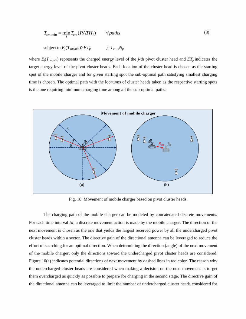
Fig. 10. Movement of mobile charger based on pivot cluster heads.
The charging path of the mobile charger can be modeled by concatenated discrete movements.
For each time interval t, a discrete movement action is made by the mobile charger. The direction of the
next movement is chosen as the one that yields the largest received power by all the undercharged pivot
cluster heads within a sector. The directive gain of the directional antenna can be leveraged to reduce the
effort of searching for an optimal direction. When determining the direction (angle) of the next movement
of the mobile charger, only the directions toward the undercharged pivot cluster heads are considered.
Figure 10(a) indicates potential directions of next movement by dashed lines in red color. The reason why
the undercharged cluster heads are considered when making a decision on the next movement is to get
them overcharged as quickly as possible to prepare for charging in the second stage. The directive gain of
the directional antenna can be leveraged to limit the number of undercharged cluster heads considered for

the direction of the charger movement. The interior angle of each service sector is 2B, where B=22o is the
half-power beamwidth of the radiation pattern in Fig. 8(b), and the bisector of the interior angle,
corresponding to the potential direction of next movement, connects the charger to an undercharged
cluster head. The time interval t is set at 2.5msec and the distance Rm between the current location and
the next location is set at 0.05m. Thus, when the mobile charger keeps shifting, the velocity of the mobile
charger is equal to (0.05m/2.5ms)=72km/hour. When staying at the same location yields the largest
received power by all the undercharged pivot cluster heads within the same or different sector, the charger
decides to do so. Figure 10(b) shows the movement of the mobile charger according to the locations of
the pivot cluster heads.
Charging by pivot cluster heads begins when every pivot cluster head becomes overcharged.
During the first stage, the mobile charger transmits the RF energy by aiming at the pivot cluster heads, but
due to the geophysical proximity of the member sensor nodes to the pivot cluster heads, many member
nodes are fairly charged as well. Nevertheless, many member sensor nodes are still undercharged when
the first stage is complete. To bring these undercharged member sensor nodes up to the target energy level
ETs, the pivot cluster heads charge the member sensor nodes that are still in need of energy. In the
beginning of the second stage energy, all the undercharged member sensor nodes broadcast messages, as
is shown in Fig. 9(b). It is assumed here that each pivot cluster head knows the list of member sensor
nodes in its cluster. After receiving all the messages from the member sensor nodes, each pivot cluster
head charges the member sensor nodes in the same cluster. Order of preference in charging can be
determined by the amount of energy needed or another criterion. If a member sensor node gets all the
energy it needs, it broadcasts a message indicating completion of charging. In the following simulations,
MAC protocol to determine the order of charging is not taken into account.
B. Charging Efficiency of Charging Scheme in Two Stages
The performance of the charging scheme in two stages is evaluated in a given
total service area with different random distributions of sensor nodes. The total service area used for the
simulations is 100m x100m. This is similar to the area of a factory, a warehouse, or a parking lot, where
many wireless sensor nodes are deployed [19][20]. Random distributions of sensor nodes are tested for
evaluation of the charging performance and all the sensor nodes are initially energy-depleted. The number
of sensor nodes NT ranges from 100 to 200. The target energy level of the member sensor nodes
ETs=2Joules, just like that for [4] and the target energy level of the pivot cluster heads ETp is adjusted
according to NT. The ETp is set significantly higher than ETs to guarantee that the pivot cluster heads not

only have enough energy for their own tasks but also can charge the member sensor nodes in their vicinity.
The charging efficiency Tf, the ratio of received power at distance d=0m to transmit power P0 of the pivot
cluster head, is set at Tf =0.02, as in [22]. The radius of the inclusion circle is set at Rcl =10m.
Table 1. Simulation parameters
Types of cluster heads
C Charging
Configuration
Antenna gain of
mobile charger
Transmit antenna
gain of pivot
cluster heads
TN /p
h
ET
ET
Pivot cluster heads 12 dB 12 dB 200 nodes 5.5 J
175 nodes 5.5 J
150 nodes 4.5 J
125 nodes 4.5 J
100 nodes 4.0 J
Cluster heads 12 dB 0 dB 200 nodes 5.0 J
175 nodes 5.5 J
150 nodes 5.5 J
125 nodes 6.0 J
100 nodes 6.0 J
The performance of the charging scheme in two stages is compared with that of other charging
schemes. One of the charging schemes for comparison is the scheme in [4]. Another charging scheme is
also in two stages with a difference in that there is an absence of pivot cluster heads with directional
antennae. Path planning of the mobile charger in the first stage is designed to charge cluster heads.
Antenna gain of the transmit antennae of the cluster heads is 0dB instead of 12dB for the pivot cluster
heads. When charging with the mobile charger in the first stage is finished, every cluster head becomes
overcharged. Unlike charging only by pivot cluster heads in the second stage, all the overcharged sensor
nodes, including the cluster heads, can charge the undercharged member sensor nodes. The target energy
level ETh with the overcharged sensor nodes in the second stage is also set according to NT, as shown in
Table 1. Since the cluster heads employ transmit antennae with 0 dB antenna gain, eq.(1) is used instead
of eq.(2). From Table 1, it is seen that the ETp is set higher than the ETh with high density of sensor nodes,
but it is set lower with low density of sensor nodes. This is because with larger NT the number of

overcharged sensor nodes increases, so that there are more sensor nodes that are able to charge
undercharged sensor nodes.
Fig.11. Simulation results: (a) total charging time; (b) number of overcharged sensor nodes as a function
of time
Figure 11 shows the total charging time for the three schemes considered. Both charging schemes
in two stages outperform the charging scheme in [4] and the charging scheme involving pivot cluster
heads provides the best performance. Since the pivot cluster heads use directional antennae, the charging
efficiency in the second stage is significantly higher than that of the other schemes in two stages. On the
other hand, charging efficiency with cluster heads of omni-directional antennae in the second stage is seen
comparable to that with pivot cluster heads employing directional antennae. Compared with the scheme in
[4], charging by overcharged sensor nodes in the second stage seems effective at reducing the total
charging time. Figure 11(b) shows the charging progress in terms of the number of charged sensor nodes
over time. Figure 11(b) suggests that the charging scheme with overcharged sensor nodes for charging in
the second stage requires substantially more sensor nodes to be overcharged in the first stage as compared
to the case with the pivot cluster heads. This is because of the waste of energy that occurs when the
overcharged sensor nodes transfer energy and the waste occurs due to the omni-directional antenna
incurring much transmission loss along wrong directions. Thus, the number of undercharged sensor nodes
that can become overcharged in the second stage is substantially smaller with the overcharged sensor

nodes used in the second stage. The simulation results obtained here are in accordance with the results in
[9], where it is stated that a directional antenna is more efficient than an omni-directional antenna for
charging applications. Figure 12 shows the energy profile of the pivot cluster heads before and after the
second stage with three different NT values. The amount of surplus energy of a pivot cluster head
increases with increased NT, and the surplus energy becomes approximately 0 after the second stage.
Fig.12. Energy level of pivot cluster heads before and after the second stage: (a) NT=100; (b) NT=150; (c)
NT=200.
IV.CONCLUSION
Review of wireless rechargeable sensor networks (WRSNs) is presented in this article. To ensure
sustainable operation of sensor networks, charging efficiency is considered important. With the large
number of existing WRSNs, energy-efficient charging schemes become critical to workplaces aiming at
low operating cost. System aspects of RF remote charging and RF energy harvesting are described. To
obtain higher charging efficiency, a directional antenna providing higher antenna gain can be adopted.
The RF remote charging scheme consisting of charging pivot cluster heads by a mobile charger with
directional antenna in the first stage and charging undercharged sensor nodes by pivot cluster heads with
directional antenna in the second stage is presented. Also, another charging scheme involving energy
trading between overcharged sensor nodes and undercharged sensor nodes in the second stage is
presented. The proposed charging schemes are expected to be particularly useful in open spaces with
many sensor nodes such as factories, warehouses, and parking lots, where sensor nodes can be densely
deployed.
References
[1] X. Jia, O. Feng, T. Fan, and Q. Lei, “RFID technology and its applications in internet of things (IoT),”
in Proc. 2nd IEEE Int. Conf. Consum. Electron., Commun. Netw. (CECNet), pp. 1282–1285, Apr. 2012.
[2] E. Hong, K. Kim, and D. Har, “Spectrum sensing by parallel pairs of cross-correlators and comb
filters for OFDM systems with pilot tones,” IEEE Sensors Journal, vol.12, no.7, pp. 2380–2383, 2012.
[3] J. Kim and J.-W. Lee, "Energy adaptive MAC protocol for wireless sensor networks with RF energy
transfer", Proc. IEEE 3rd ICUFN, pp. 89-94, 2011.
[4] L. Fu, P. Cheng, Y. Gu, J. Chen and T. He, "Optimal Charging in Wireless Rechargeable Sensor
Networks", IEEE Trans. Veh. Technol., vol. 65, no. 1, pp. 278-291, Jan. 2016.
[5] Y. Shu, H. Yousefi, P. Cheng, J. Chen, Y. J. Gu, T. He, K. G. Shin, Near-Optimal Velocity Control
for Mobile Charging in Wireless Rechargeable Sensor Networks, IEEE Transactions On Mobile
Computing, pp.1699-1713.
[6] I. Stark, "Invited talk: Thermal energy harvesting with thermo life", Proc. Int. Workshop Wearable
Implantable BSN, pp. 19-22, 2006
[7] O. Galinina, H. Tabassum, K. Mikhaylov, S. Andreev, E. Hossain, and Y. Koucheryavy, "On
feasibility of 5G-grade dedicated RF charging technology for wireless-powered wearables,"IEEE
Wireless Communications, vol. 23, no. 2, pp. 28–37, Apr. 2016.
[8] Y. Zafar, J. Park, and D. Har, "Random clocking induced DPA attack immunity in FPGAs", IEEE Int.
Conf. on Industrial Technology, pp.1068-1070, 2010.

[9] Michael Buettner , Ben Greenstein , David Wetherall, Dewdrop: an energy-aware runtime for
computational RFID, Proceedings of the 8th USENIX conference on Networked systems design and
implementation, March, 2011.
[10] Liu, Kuang-hao and Phone Lin. "Toward Self-Sustainable Cooperative Relays: State Of The Art And
The Future". IEEE Commun. Mag. vol.53, no.6, pp.56-62. 2015.
[11] D. Mishra, S. De, S. Jana, S. Basagni, K. Chowdhury and W. Heinzelman, "Smart RF energy
harvesting communications: Challenges and opportunities", IEEE Commun. Mag., vol. 53, no. 4, pp.
70-78, 2015.
[12] Y. Xiao, D. Niyato, Z. Han and L. A. DaSilva, "Dynamic Energy Trading for Energy Harvesting
Communication Networks: A Stochastic Energy Trading Game", IEEE J. Select. Areas Commun., vol. 33,
no. 12, pp. 2718-2734, 2015.
[13] A. Madhja, S. Nikoletseas and T. P. Raptis, "Hierarchical collaborative wireless charging in sensor
networks", IEEE WCNC, pp.1285-1290, 2015.
[14] C. Wang, J. Li, Y. Yang and F. Ye, "A hybrid framework combining solar energy harvesting and
wireless charging for wireless sensor networks".
[15] E.W. Forgy, “Clustering analysis of multivariate data: efficiency versus interpretability of
classifications,” Biometrics, vol.21, pp.768-769, 1965.
[16] E. Ibarraa, A. Antonopoulosa, E. Kartsaklib , C. Verikoukisa, HEH-BMAC: hybrid polling MAC
protocol for WBANs operated by human energy harvesting. Telecommunication systems, 2015, 58.2:
111-124.
[17] I. Park, D. Kim, and D. Har, “MAC Achieving Low Latency and Energy Efficiency in Hierarchical
M2M Networks with Clustered Nodes,” IEEE Sensors Journal, vol.15, no.3, pp.1657-1661, 2015.
[18] P. Blasco, D. Gündüz, M. Dohler, Low-complexity scheduling policies for energy harvesting
communication networks, Information Theory Proceedings (ISIT), 2013 IEEE International Symposium
on, 1601-1605.
[19] S. Lee, D. Yoon and A. Ghosh, "Intelligent parking lot application using wireless sensor
networks",Proc. Int. Symp. Collaborative Technol. Syst. (CTS), pp. 48-57, 2008.

[20] C. R hrig and S. Spie er, Trac ing of Transport ehicles for Warehouse Management using a
Wireless Sensor Network," in 2008 IEEE/RSJ International Conference on Intelligent Robots and
Systems (IROS 2008), pp. 3260-3265, Sept. 2008.