1996 toyota corolla - the national locksmith - home · parisienne 1985-1990 sunbird 1985-1994...
TRANSCRIPT

AUTUMN1996
The Official Publication of the
NATIONAL LOCKSMITHAUTOMOBILE ASSOCIATION™
1996 Toyota Corolla ..........................................................page 1
Publisher's Page................................................................page 3
Director's Page ..................................................................page 4
1996 GMC Savana...........................................................page 13
Auto Parts.........................................................................page 26
1996 Nissan Pathfinder..................................................page 27
Ford 8 Wafer Ignition Removal Kit.............................page 37
™
2. To open this car we used anopening tool from the High-Techset, but any similar tool will do.You will need a couple of goodwedges also.
1996 Toyota Corollaby Michael Hyde
OPENING THE CAR
1. The Toyota Corolla is one ofthe best selling cars in theUnited States. The Corolla is afavorite of the rental carcompanies because of its smallsize and dependability.
(Continued on page 5)

Autumn 1996 3
Well as you know by now, the 1996 AutoSmart is now out and available.It is completely updated up through 1996 models and also includes a
lot of 1997 information. Have you ordered your extra copy yet?
We recently offered a great deal to NLAA members due to renew theirmembership. All-Lock was kind enough to give to us a quantity of FordStarter Kits, designed just for the NSO.
The kits contain an uncombinated Ford ignition as well as a casecontaining a number of each tumbler, springs, and shutters. As a bonus, theyalso included an uncombinated Toyota ignition.
Many thanks to All-Lock for the donation, and to get yours, use therenewal form you were recently sent. If you are not quite due to renew yet,you can still get your free kit by renewing early. Just send us a check foryour $125 dues, and include your NLAA membership number and mentionthe All-Lock kit.
The NLAA pledges not only to continue providing you with criticalautomotive service information, but also to give you great value for yourmembership dollar.
Here's something else you might be interested in. The National Locksmithmagazine now has an extensive website online. There is a great deal of
technical information available there. And you can also submit your ownquestions online to get technical support from your fellow locksmiths.
The site is www.TheNationalLocksmith.com. To get into the securedlocksmith area you will need a user name and a password, so here they are.Both are case sensitive.
User name: national
Password: G5fh84
Happy web surfing and enjoy this issue of the NLAA!
FROM THE PUBLISHER
Marc Goldberg
National Locksmith Automobile Association™
PublisherMarc Goldberg
DirectorGreg Mango
Printed in U.S.A.NLAA, a division of
National Publishing Co.Publishers of
THE NATIONAL LOCKSMITH
1533 Burgundy ParkwayStreamwood, Illinois 60107
Phone 630-837-2044Fax 630-837-1210
E-mail address: [email protected]
Unsolicited manuscripts areaccepted, but must include
SASE.© 1996 National Publishing Co.
All Rights Reserved
Autumn 1996
Happy Web Surfing!

Operation Air BagA customer calls and inquires as to
what the charges would be to makean ignition key for a 1985 BuickCentury. You know you will need topull the steering wheel to release theignition for the key code. Thishowever, should prove to be fairlypainless so you quote the customeryour normal fee plus a trip charge forthis service. The customer agrees,and you head to the call.
When you arrive, you notice thatsomething isn’t quite right. Thesteer-ing wheel is not a factorywheel. On the surface of the wheel,the words SRS-40 is engraved andyou notice there is a “WARNING”sticker on the side of the wheel thatstates: “This steering wheel/SRS-40system should be serviced by factoryauthorized personnel only. Tamperingmay result in serious injury.”
Should you encounter such a situ-ation, take the warning serious. Whatyou have stumbled upon is your veryfirst Midas Muffler after market install-ed air bag. That’s right, Midas Muffler.
The system is referred to as the“SRS-40 Supplemental RestraintSystem,” and is manufactured byBreed Technologies of Lakeland,Florida. Currently, Midas servicetechnicians are the only onesauthorized to service the SRS-40. Thisair bag system is very different fromthe ones currently in use by theoriginal car manufacturers. There is avery real possibility of an accidentaldeployment and serious personalinjury if not handled properly.
The following is a list of vehicleswhich can currently be retrofittedwith the SRS-40 SupplementalRestraint System:
BUICK Century* 1985-1992 Electra* 1985-1990 Electa Park Avenue 1985-1990 LeSabre 1985-1991Regal 1988-1993 Skyhawk 1985-1991 Skylark 1985-1993 Somerset 1985-1987
CADILIAC Cimarron 1985-1988
CHEVROLETBeretta** 1987-1990 Caprice 1985-1990 Cavalier 1985-1994 Lumina*** 1990-1994 Celebrity 1985-1990 Corsica** 1987-1990 Geo Prizm 1990-1992
CHRYSLER Eagle Talon 1990-1994Plymouth Laser 1990-1994
FORD/MERCURYCougar 1989-1993Crown Victoria 1986-1989 Grand Marquis 1986-1989 Lincoln Town Car 1986-1989 LTD Country Squire Wagon1986-1989 Thunderbird 1989-1993
HONDAAccord 1986-1991
MITSUBISHIEclipse 1989-1994
OLDSMOBILE88 Royale 1986-1991 Achieva 1992-1993 Cutlass Calais 1985-1991 Cutlass Ciera 1985-1993 Ninety Eight 1985-1990Cutlass Cruiser Wagon 1985-1993 Cutlass Supreme 1988-1993 Delta 88 1986-1991 Firenza 1985-1988
PONTIAC 6000 1985-1991 Bonneville 1987-1991 Grand Am 1985-1993 Grand Prix 1988-1993Parisienne 1985-1990 Sunbird 1985-1994 Tempest 1987-1991
TOYOTACamry 1987-1991 Corolla 1988-1992 *Does not include wagon.**Cruise control not available ***Passenger cars only. Not AVP
Available For These Trucks:CHRYSLER
Caravan 1985-1990 Grand Caravan 1985-1990 Grand Voyager 1985-1990 Town and Country 1990 Voyager 1985-1990
GENERAL MOTORS Astro Mini-Van 1985-1993 Blazer 1985-1994 Bravada 1991-1994 Chevy Sportsvan 1985-1995 Chevy Van 1985-1995 CK Pickup 1985-1995 GMC Van 1985-1995 Jimmy 1985-1994Yukon 1985-1994 S-10 Pickup & Blazer 1985-1994 S-15 Jimmy 1985-1994 S-15 Pickup 1985-1994 Safari Mini-Van 1985-1993 Sierra 1985-1995 Sonoma 1985-1994 Suburban 1985-1995 Vandura 1985-1995
FORDBronco 1988-1993 BroncoII 1989-1990 E-150 1988-1991 E-250 1988-1991 E-350 1988-1991 Explorer 1991-1994 F-150 1988-1993 F-250 1988-1995 F-350 1988-1995 Ranger 1989-1994
JEEP Cherokee 1985-1994
MAZDAB-Series Pickup 1993-1994Navajo 1991-1994
The next time you receive a callto make an ignition key that willrequire pulling the steering wheelto accomplish, ask if the vehicle isequipped with an Air Bag RestraintSystem. If it is, ask if it is originalequipment, or after market. Theanswer to those questions couldseverely alter your initial response,and service charges.
DIRECTOR’SPAGE
GREG MANGO
4 Autumn 1996 National Locksmith Automobile Association

1996 Toyota Corolla
National Locksmith Automobile Association Autumn 1996 5
(continued from front cover)
3. The linkage is vertical on this model and isprotected with a black plastic tube.
4. At the bottom of the linkage rod is where thetube ends, from this point the linkage rod isexposed and easily accessible. Lift up on thebottom of the rod to unlock the car.
5. To service the ignitioncylinder you can pop-off thecolored trim ring or leave it onsince it wraps around the lockcylinder and is not part of thedash.
IGNITION LOCK
6. The knee bolster has to be lowered to access the active retaineron the ignition. Remove the access cover below the ignitioncylinder. You will need to remove the screw under the cover. Thereis a simular access cover on the left side of the column in wherethe screw underneath needs to be removed.

6 Autumn 1996 National Locksmith Automobile Association
7. There are two 10mm bolts on the bottom of the knee bolster,one in the right corner and one in the left corner behind the sidepanel which need to by removed.
8. With the knee bolster out ofthe way it is easy to accessthe ignition retainer. Insert aworking key and rotate it tothe “ACC” position. Depressthe retainer and remove thelock cylinder.
9. The ignition cylinder.
10. To disassemble theignition cylinder you mustremove the tru-arc retainer onthe back end of the cylinderplug.
11. This lock has a face cap on it that must be removed. The facecap is held to the cylinder by both a roll pin and two staked posts.The hole the roll pin sits in is concave. The easiest way to removeit is to drill a 7/64” hole on the side of the housing to lift up the pinfrom the bottom.

12. The two stamped posts areshown.
13. The posts are partof the cylinder face capand travel through the
front of the cylinderbody and then are
“peened” or “staked” sothere is enough extrametal overlapping to
hold the cap in place.Use a pin punch to
evenly tap on each postuntil the cap is
removed. Rememberyou must do this evenlyor you can break one of
the posts.
14. The face cap removed, is shown.
15. To slide out the cylinder plug you will need aworking key.
16. The cylinder plug contains two sets of splittumblers in positions four and seven from the bow.
17. The door lock cylinder is partof the door handle assembly.
DOOR LOCK
National Locksmith Automobile Association Autumn 1996 7

8 Autumn 1996 National Locksmith Automobile Association
18. The door panel must be removed to servicethe door lock cylinder.
19. First, lift up the armrest pad and unsnap it.
20. Remove the two phillips head screws that arefound under the pad.
21. Remove the phillips head screw that holdsthe inside release to the door. Disconnect thelinkage to the release.
22. This model haselectric door locksand power windows.Lift up the doorcontrols from thefront and disconnectthe wiringconnectors. Now youcan remove the doorpanel. It uses thestandard plasticpush-in clips.
National Locksmith Automobile Association Autumn 1996 9
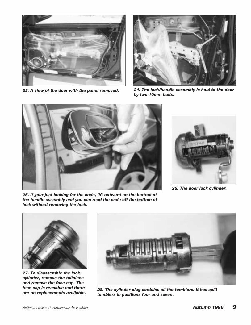
23. A view of the door with the panel removed. 24. The lock/handle assembly is held to the doorby two 10mm bolts.
25. If your just looking for the code, lift outward on the bottom ofthe handle assembly and you can read the code off the bottom oflock without removing the lock.
26. The door lock cylinder.
27. To disassemble the lockcylinder, remove the tailpieceand remove the face cap. Theface cap is reusable and thereare no replacements available.
28. The cylinder plug contains all the tumblers. It has splittumblers in positions four and seven.

10 Autumn 1996 National Locksmith Automobile Association
29. The door lock cylinder disassembled. 30. The trunk lock cylinder islocated under the rear taillightassembly.
TRUNK LOCK
31. The cloth-like material liner must be pulledback or removed to access the trunk lockcylinder and taillight assembly.
32. Remove the 10mm nuts that hold the taillightassembly on. Next remove the 10mm bolts thathold the trunk lid latch on. Next you will have togently unsnap all the plastic clips. Do not pull onthe light assembly or you will crack the plasticouter lens, like I did.
33. A view of the plastic locking clips.34. A view of the backside of the taillightassembly.

National Locksmith Automobile Association Autumn 1996 11
35. The trunk lidwith the taillight
removed.
36. Finally,remove the two10mm nuts thathold in the lockcylinder anddisconnect thelinkage rod.
37. To disassemble the trunklock cylinder, remove the
tailpiece and the face cap.The face cap is reusable and
there are no replacementsavailable.

12 Autumn 1996 National Locksmith Automobile Association
GLOVE BOX LOCKThere is no glove box lock on this model.
GENERATING FIRST KEYMethod 1). Check owners manual for code, written in
by the dealer or fellow locksmith.
Method 2). Remove passenger door cylinder and readcode stamped on lock.
Method 3). Disassemble door cylinder or trunkcylinder and decode wafers to make master key.
SPECIFICATIONSCode Series: 10000-15000
Key Blank: Ilco X217/TR47/ Silca TOY43
Reed Codes: 11-02-064
HPC 1200CM #: XF208, PUNCH PF208
M.A.C.S: 2
First Cut: .885 (measured from tip)
Cut to Cut: .090
Depths: 1=.323, 2=.299, 3=.276, 4=.252
FRAMON: Use Ford 5 PIN Spacing Clip, Set
Starting Cut @ .017 (First Cut From Bow).
38. Be aware of the ball bearing in the back ofthe lock as you disassemble it. There is anaccess hole that you will use to re-load the ballbearing. 39. It is common for dust shutter assemblies on
these locks to fall apart as you remove the facecap.
40. The trunk cylinder plug contains all thetumblers. It has split tumblers in positions four andseven. The trunk lock disassembled, is shown.

National Locksmith Automobile Association Autumn 1996 13
By Michael Hyde
1996 GMC Savana
1. Lets take a look at the new 1996 GMC SAVANA. This new van is a full-size vanmade alongside with the new Chevy Express. This van we serviced had the new GM10-cut locking system and is a “one-key” vehicle. This van uses the GM 10-cut“CSS” column, found mostly on trucks.
2. To open this van weused two wedges and ahorizontal slide linkage
tool. Insert the tool aboutmidway on the door.
OPENINGTECHNIQUE

14 Autumn 1996 National Locksmith Automobile Association
3. Insert the tool straight downand make contact with secondhorizontal linkage rod, justnudge the tool and the van willunlock. The linkage rod slidesvery easy and just bumping itwould unlock the door. It isfunny to see that GM heavilyshielded the latch linkage rodand left this big opening forthe lock linkage rod.
4. Here is a tip from Steve Young over at Tech-Train. Remove the rear license plate light and you canreach your finger in and move the bell crank to the unlock position. Thanks Steve.
5. On the CSS columns there is no secondarylock cylinder housing. This means that thelock cylinder housing is an integral part of
the steering column. The lock cylinder plugis inserted directly into that housing. When
these columns are built, they are assembledwith the shroud, ignition housing, steeringwheel and so on. The ignition lock cylinder
plug is inserted after the column arrivesfrom the column manufacture. Since thewings of the lock cylinder plug are larger
that the opening in the shroud you can notremove the upper section of the shroud.
IGNITION SERVICE

National Locksmith Automobile Association Autumn 1996 15
6. The underside view of the CSS column. 7. To gain easier access to the bottom of theshroud you can unsnap part of the knee bolster.This will give you a little extra room whenworking on the ignition. Remove the two Torxscrews that hold the bottom half of the shroud tothe column. Adjust the column to its mid-heightposition. Now remove the tilt-column lever. Thelever pulls right out.
8. The next step is to gently and I mean gentlyunsnap the forward section of the shroud. Therear section of the shroud is hinged and will notunsnap. The lower section of the shroud can beremoved by pushing it towards the front of thetruck, to release it from the molded plastichooks. Or you can push the shroud out of yourway.
9. There are two External Torx screws to beloosened. One is on the left side of the column.The screw goes through a plate and to a postthat is connected to the upper shroud. It isimportant to hold the post and not allow it to turnas you loosen the screw. Use a 4mm socket ordriver for this procedure.

16 Autumn 1996 National Locksmith Automobile Association
10. The other screw that holdsthe upper shroud to the columnis on the right side of the columnand is forward of the lockhousing. Loosen this screw butdo not remove it. Use a 4mmsocket or driver for thisprocedure.
IMPORTANT NOTE: The cylinderplug only releases when it is inthe “Start” position. You candisconnect the battery or youcan put the truck into gear, suchas Drive, and then turn theignition to Start and depress theretainer. When the truck is ingear, the transmission safetyswitch does not allow the starterto engage. Be Careful, if youhear the starter engage, turn theignition switch to the OFFposition immediately.
11. Insert the working key and rotate thecylinder to the “ON” position. Put the truck in“Drive” and make sure the brake is on. Use aGM 10-cut ignition release tool and rotatethe plug to the “Start” position. Depress theretainer that is located on top of the housing.The cylinder plug will now slide out. (Theignition retainer tool that is pictured was partof a GM 10-cut servicing kit purchased fromA-1 Security. A GM 10-cut ignition retainertool can be purchased from Tech-TrainProducts, also.)
12. The ignition housing is pictured. Thedrop-in hole for the retainer is shown withtool tip protruding through. The plasticbuzzer switch is to the right of the tool.

National Locksmith Automobile Association Autumn 1996 17
13. The ignition cylinder plug. This plug containsnine tumblers in positions 1 through 9. This lockuses a side-bar.
14. A close-up view of the code that is stampedon the cylinder plug. The code looks as if it wasput on in a “dot-matrix” design, and can bedifficult to make out the individual digits.
15. The ignition tumblers are pictured.
16. Thetumblers canbe found in theStrattecPinning Kitnumber702767.

18 Autumn 1996 National Locksmith Automobile Association
17. The door lock is part of the outside doorhandle.
DOOR LOCK SERVICING
18. To service the door cylinder it is necessary toremove the inside door panel.
19. First, remove the twophillips head screws that holdon the arm-rest.
20. Next, remove the plastic cover plate that is behind the insidedoor release handle. It unsnaps.

National Locksmith Automobile Association Autumn 1996 19
21. There are two phillips head screws that haveto be removed behind the door release handle. 22. There is a plastic trim cover that sits on top
of the door panel, on the forward door post. Itsnaps and has to be removed.
23. The panel uses plastic hooks, just lift up andremove the panel. That’s it, your done.
24. Thedoor withthe panelremoved.
20 Autumn 1996 National Locksmith Automobile Association
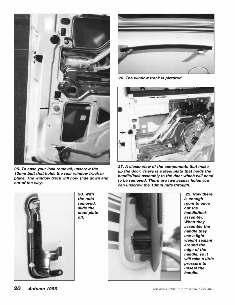
25. To ease your lock removal, unscrew the10mm bolt that holds the rear window track inplace. The window track will now slide down andout of the way.
26. The window track is pictured.
27. A closer view of the components that makeup the door. There is a steel plate that holds thehandle/lock assembly to the door which will needto be removed. There are two access holes youcan unscrew the 10mm nuts through.
28. Withthe nutsremoved,slide thesteel plateoff.
29. Now thereis enoughroom to edgeout thehandle/lockassembly.When theyassemble thehandle theyuse a lightweight sealantaround theedge of thehandle, so itwill take a littlepressure tounseal thehandle.
National Locksmith Automobile Association Autumn 1996 21
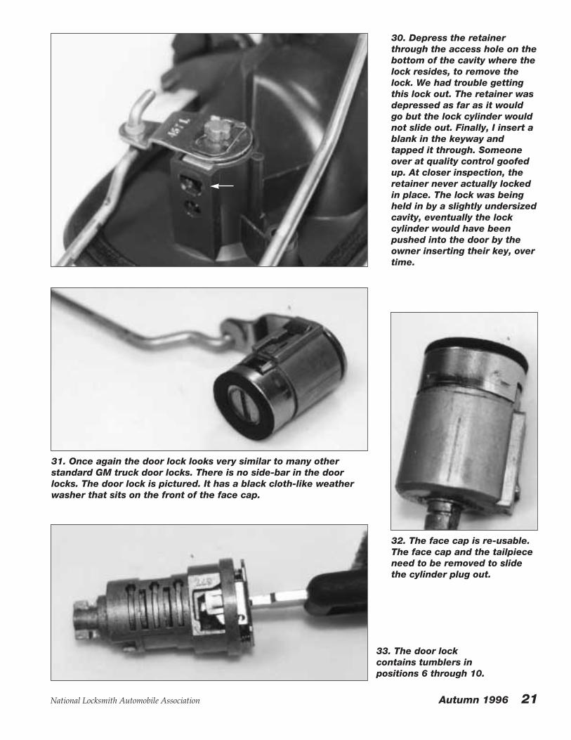
30. Depress the retainerthrough the access hole on thebottom of the cavity where thelock resides, to remove thelock. We had trouble gettingthis lock out. The retainer wasdepressed as far as it wouldgo but the lock cylinder wouldnot slide out. Finally, I insert ablank in the keyway andtapped it through. Someoneover at quality control goofedup. At closer inspection, theretainer never actually lockedin place. The lock was beingheld in by a slightly undersizedcavity, eventually the lockcylinder would have beenpushed into the door by theowner inserting their key, overtime.
31. Once again the door lock looks very similar to many otherstandard GM truck door locks. There is no side-bar in the doorlocks. The door lock is pictured. It has a black cloth-like weatherwasher that sits on the front of the face cap.
32. The face cap is re-usable.The face cap and the tailpieceneed to be removed to slidethe cylinder plug out.
33. The door lockcontains tumblers inpositions 6 through 10.

22 Autumn 1996 National Locksmith Automobile Association
34. The door lock, disassembled.
35. The type of tumblers used in the door lock.Note serration’s.
36 The rear door lock is part of the door handleand the license plate holder.
REAR DOOR LOCKSERVICING
37. A view of the inside door panel. This van hashad the interior upgraded by a custom interiorcompany that specializes in upgrading vans fordealers.
38. The inside doorrelease. There is a trimplate covering two phillipsscrews. Unsnap the coverand remove it.

National Locksmith Automobile Association Autumn 1996 23
39. Remove the two phillips head screws.40. The trim plate can now be removed, youmust disconnect the wiring connector.
41. The upper door panel section, where it thinsout around the window on the left and right side,has fasteners that must be unsnapped. Once theupper fasteners are unsnapped, you can simplylift upward to remove the panel. It also usesplastic hooks to lock it into the door body, as withthe front doors. 42. A view of the door with the panel removed.

24 Autumn 1996 National Locksmith Automobile Association
43. A look at the steel plate that holds the handleassembly to the door. It also has two 10mm nutsthat hold it to the door. These nuts do not have tobe removed as the lock cylinder can be easilyremoved. The lock on this door also had aproblem with removal. We had to insert akeyblank and tap on it to remove the cylinderfrom the plastic handle assembly.
44. The rear door lock cylinder.
45. The re-usable face
cap andtailpiecemust be
removed toslide the
cylinder plugout.
46. The reardoor lockcontainstumblers inpositions 6through 10.
47. The rear door lock,disassembled.

National Locksmith Automobile Association Autumn 1996 25
GLOVE BOX / COMPARTMENT LOCK
We found no glove box lock orcompartment lock on this vehicle.
MAKING FIRST KEYMethod 1). Call GMC Roadside
for the key code.
Method 2). Use A-1’s GM 10-cutIgnition pick and decoder serviceset. It will allow you to pick theignition cylinder and then removethe cylinder to decode it, withoutdrilling or damaging the lock. Thiswill give you cuts in positions 1through 9.
(A-1 Security can be reached at804-359-9003)
Method 3). Use AAble’s GM 10-Cut tool to pick the lock to the“ON” position and remove tocheck for the code or decode thelock. (AABLE Locksmiths can bereached at 718-847-1377)
Method 4). Use a “Dremel” toolto slice a slot where the side-barwould be on the ignition housing.Put light pressure on the side-barand then “rake” the tumblers. Onceyou have picked the cylinder, DO
NOT ROTATE THE CYLINDER,until you insert a key that has beencut down to all number fourdepths and has no high spots. Usethe prepped key to turn thecylinder. This will prevent youfrom breaking the key buzzerswitch. Average cost of switch$132.00. If the truck is anautomatic, put it in “Drive” (whichwill block the truck from startingbecause of the ‘neutral safetyswitch’) and turn the cylinder tothe “Start” position to depress theactive retainer on the top of thecylinder housing. If the truck is astick-shift, do not depress theclutch (which will block the truckfrom starting because of the‘neutral safety switch’) and turnthe cylinder to the “Start” positionto depress the active retainer on thetop of the cylinder housing. Justthe plug will come out, as thiscylinder plug does not have ahousing of its own and fits directlyinto the column housing.
IMPORTANT NOTE: The cylinder plug only releases
when it is in the “Start” position.You can disconnect the battery oryou can put the truck into gear,such as Drive, and then turn the
ignition to Start to depress theretainer. When the truck is in gear,the transmission safety switch doesnot allow the starter to engage. BeCareful, if you hear the starterengage, turn the ignition switch tothe OFF position immediately.
SPECIFICATIONS: Code Series: AA00-7N45
Key Blank: Ilco P1107-B86 / B89,Silca GM39
Reed Codes: 12-01-001
HPC 1200CM #: CF215
M.A.C.S.: 2
Center of first cut: 1.034 (fromtip)
Cut to Cut: .092
Depths: 1=.315, 2=.290, 3=.265,4=.240
FRAMON: Lay tip stop clip flatagainst left side of vise, then tipstop key against clip.
First cut @ .216.
NOTES:

26 Autumn 1996 National Locksmith Automobile Association
Inside Industry NewsBy Michael Hyde
In this issue of the NLAAnewsletter, we continue with ournews about the auto industry.
G.M. TRUCK COLUMNSSome G.M. passenger cars,
starting in 1997 will be using theignition lock assemblies previouslyonly found in the truck line. Theassemblies are cal led “CSS”columns. These are all using thenew 10-cut keyway.
INFINITI NEWSThe 1997 Q45 was just released.
It uses the new Pathfinder keywayand a Transponder. The keys canbe cut as any conventional key,except special equipment is neededto program the new key into thecars computer. This equipment isonly available to Infiniti dealers.
Why does Curtis have an insidetrack with Infinti. In my area of thecountry, the dealers are told theyhave to buy a special clipper to cutthese keys. The clipper was re-engineered to allow the new largetransponder head key to work in it.I had to travel down to the localdealer I do work for and show theregional service/parts rep. that mydealer did not need any new keycutter. I do all their key and lockwork. This cutter is not going to besold to locksmiths.
The 1998 Q45 will have sideimpact Airbags.
A slightly re-designed Pathfinderwill be sold as an Infiniti QX4.
FORD EXPEDITIONThere is another new Ford out
there, its called an Expedition. TheExpedition uses the new Ford 8-cutkeyway and will have the PATSsystem as standard equipment. TheExpedition is a sport utility vehiclethat replaced the Bronco.
AUDI NEWSThe Audi A6 is a high-security
keyway with a 2-track internalkeyway. The factory key has aTransponder in it. I made keys toone and it started and ran just fine.The key I used did not have atransponder in it. The Audi A4uses a conventional keyway with atransponder also. The car also ranwithout a transponder in the key.
1995 RANGE ROVERThe newer body style 1995 Range
Rover 4.0 uses a 4-track keyway.The dealer insists that it has atransponder in the key, it mighthave. The car will start and runwithout a transponder key, butonly the 1995 model.
BMW TRANSPONDERIs there a way to defeat the BMW
transponder system? We’ll let youknow. If there is a will, there mightbe a way.
VOLVODo you do high-security car
work? Do you have space & depthkeys for both Volvo 4-tracksystems. There are two differentsets needed. One set is for the earlyversion used between approx-imately 1988 through 1992. Thenewer set, that is in current use,started approximately in 1993. Thesets can not be interchanged.
Volvo will start changing all thenames of its models. Someexamples could be: Current Model850 = S80 or V80. Current Model960 = S90 or V90.
LEXUS NEWSThe new 1997 ES300, no longer
has the built-in remote button onthe key. This model now uses a key“fob” for the remote functions.
The 1997 LS400 has atransponder in the key. There is away around their system, we’ll letyou know next issue after somemore testing.
RECALL NEWSThe 1995 Geo Tracker has bad
welds on the steering wheel andcould break apart.
1992 BMW models: 318i, 318iS,325i, 325iS, 525iT and 91-92 525i,535i, 735i, 735iL, 750iL, 850i andM5. The above models havedefect ive driver-side Airbagcontact rings. Don’t work on thesecars unless they have been repairedby the dealer.
MERCEDES M-CLASSThe new Mercedes sport-utility
vehicle being built in Alabama willbe arriving at dealers in mid 1997.It will be given the “M” classdesignation.
NEW BUGVW has decided to bring back
the Beetle. It has a new modernlook. It is being built in Mexico.Expect it in the model year 1998.
1997 TOYOTA CAMRYThe 1997 Toyota Camry has a
completely re-designed exterior.
1997 CADILLACSAll 1997 Cadillac models (except
Catera) will have an option called“OnStar”. This option will letCadillac owners call and ask fordirections. Among other thingsthey can call and have their carunlocked via a cell phone receivercircuit hooked up to the carscomputer.
DISAPPEARING MODELSThe following models will
disappear for 1997. Infiniti G20,Mazda RX-7 and the Nissan 300ZX.

National Locksmith Automobile Association Autumn 1996 27
The 1996 Nissan PathfinderBy Michael Hyde
1. The 1996 Nissan Pathfinder was re-designed for this model year. It is thefirst model to go to the new Nissan keyway.
2. The new keyway has 10 cuts on it and fourdepths. There are no codes to be found on thevehicle.
3. This vehicle has a horizontal linkage that isfairly easy to attack. To open this truck, we useda reverse horizontal slide linkage tool. It can be alittle tricky hooking on to the rod, but be patientyou’ll get it.
OPENING
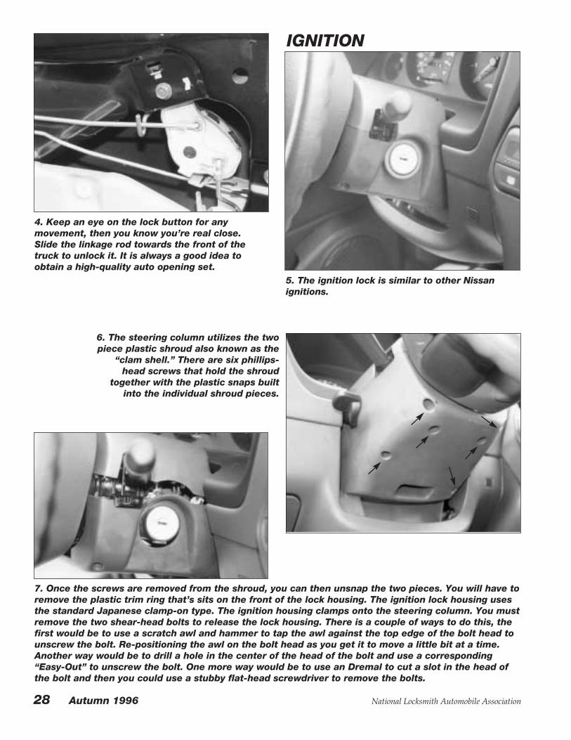
4. Keep an eye on the lock button for anymovement, then you know you’re real close.Slide the linkage rod towards the front of thetruck to unlock it. It is always a good idea toobtain a high-quality auto opening set.
IGNITION
6. The steering column utilizes the twopiece plastic shroud also known as the
“clam shell.” There are six phillips-head screws that hold the shroud
together with the plastic snaps builtinto the individual shroud pieces.
7. Once the screws are removed from the shroud, you can then unsnap the two pieces. You will have toremove the plastic trim ring that’s sits on the front of the lock housing. The ignition lock housing usesthe standard Japanese clamp-on type. The ignition housing clamps onto the steering column. You mustremove the two shear-head bolts to release the lock housing. There is a couple of ways to do this, thefirst would be to use a scratch awl and hammer to tap the awl against the top edge of the bolt head tounscrew the bolt. Re-positioning the awl on the bolt head as you get it to move a little bit at a time.Another way would be to drill a hole in the center of the head of the bolt and use a corresponding“Easy-Out” to unscrew the bolt. One more way would be to use an Dremal to cut a slot in the head ofthe bolt and then you could use a stubby flat-head screwdriver to remove the bolts.
5. The ignition lock is similar to other Nissanignitions.
28 Autumn 1996 National Locksmith Automobile Association

National Locksmith Automobile Association Autumn 1996 29
8. The ignition lock is shown.
9. The ignition housing uses a face cap that is a partof the lock housing. The face cap is held to the lockhousing by way of the two opposing roll pins.
10. I usually drill a 7/64” hole directly next to theroll pin and then use a pin punch to lift out thepin. Remember for this to work easily you mustdrill directly next to the pin, even slightly cuttingthe side of the pin as you drill is the best method.
11. Now that the roll pins have been removed, youcan slide out the ignition cylinder and the face cap.
12. You do nothave to worry aboutflying springs orball bearings withthis lock. Thosemovingcomponents havebeen built into thecylinder housingand cylinder plug.Previous versionsof similar Nissanignitions this wasnot the case.
13. The ignition cylinder is shown. The electronicbuzzer switch can be removed or left on for re-keying, it does not matter.

30 Autumn 1996 National Locksmith Automobile Association
14. The cylinder plug has a small pointed springloaded retainer on the end. Depress the retainerto slide the cylinder plug out of the cylinderhousing.
15. The cylinder plug uses ten wafers and fourdepths. Don’t worry, the tumblers from the ASPBMW kit #A-13-101 can be used to service thismodel.
16. The ignition cylinder is shown disassembled. The assemblyconsists of the lock housing, the cylinder housing, the cylinderplug, the lock face cap and the two roll pins.
17. The door lock is shown.The lock cylinder is separatefrom the outside door handle,as with many late modelNissans.
DOOR LOCK
18. To service the door lockcylinder you must remove thedoor panel.

National Locksmith Automobile Association Autumn 1996 31
19. Remove the plastic trim ring that sits on topof the inside door release handle. It unsnaps butbe gentle. Do not remove the screw that isconcealed under the trim cover in the center ofthe door release.
20. The rear section of the armrest can beunsnapped.
21. With the rear section unsnapped, unsnap theforward section of the armrest.
22. Disconnect the wiring connector from theforward section of the armrest.
23. Next, remove the three 10mm screws thatsecure the armrest and door panel.
24. The door panel is also held to the door bodyby means of plastic push-in style fasteners.These fasteners are very tight-fitting and if youtry to man-handle the panel you will end updestroying it. It is important for you to unsnapeach fastener one-by-one. The door body withthe panel removed, is shown.

32 Autumn 1996 National Locksmith Automobile Association
25. To gain easy access to the door lock, youshould remove the lower rear window track. Thewindow track is held in place by a single 10mmbolt. Remove the bolt and slide the window trackout of the way.
26. There is a metal anti-theft lock protector thathas to be removed.
27. It is held in place by a 10mm nut, that can beaccessed through a cut-out in the door. 28. A view of the anti-theft lock protector device.

National Locksmith Automobile Association Autumn 1996 33
29. The door lock cylinder is held to the door withstandard horseshoe style metal clip. Remove theelectronic switch from the lock cylinder. You donot need to mark how it came off, it can only goback on in one position.
30. The door lock is shown. The ASP replacementcap is part number P-16-213.
31. The door lock cylinder can be disassembledby removing the face cap and the tailpiece. Thetailpiece can only go back on in one position.
32. The door lock has a new type of plug springfor Nissans. It is easily removed and replacedwhen servicing the lock cylinder.
33. The door lock plug contains eight out of theten tumblers, in positions three through ten. TheASP tumbler kit for this is the also the BMW kit,part number A-13-101.
34. The door lock disassembled. The door lockcylinder consists of the cylinder housing, thecylinder plug, face cap, rubber gasket, tailpieceand retainer, cylinder plug spring andcombinations tumblers and associated springs.

34 Autumn 1996 National Locksmith Automobile Association
REAR DOOR LOCK
35. The rear door or hatch hasa two position lock cylinder.Turn the key in the lock to theleft and it will release the reardoor. Turn the key in the lockto the right and it will releasethe rear door glass.
36. To access the rear door lock cylinder it is necessary to removethe plastic door panel.
37. There is a pull handle on the door. The endshave an access door built in.
38. Gently open the little plastic access doors toget at the two 10mm bolts. You will have toremove the bolts.
39. Now the onlything holding theplastic panel arethe plastic push-in style fasteners.Unsnap the panelcarefully as to notbreak anyfasteners.

National Locksmith Automobile Association Autumn 1996 35
40. The lock cylinder is held to the door by means of ametal horse-shoe style clip.
41. There are two linkage rods connected tothe tailpiece of the lock. There is also anelectronic switch attached to the lock cylinder.
42. The rear door lock cylinder. 43. To disassemble the lock cylinder you willhave to remove the tailpiece and the face cap.The replacement face cap is the same for thedoors and is ASP part number P-16-213.
44. The door lock plug contains eight outof the ten tumblers, in positions threethrough ten. The ASP tumbler kit for thisis the also the BMW kit, part number A-13-101. 45. The door lock disassembled.

36 Autumn 1996 National Locksmith Automobile Association
SPECIFICATIONS Code Series: 00001 - 22182
Key Blank: Ilco X237 / Ilco/EZDA34 / Silca NSN14 / CurtisDA34
Reed Codes: N/A
HPC 1200CM: N/A
M.A.C.S.: 2
Center of first cut: 1.034 (fromtip)
Cut to Cut: .083
Depths: 1=.333, 2=.307, 3=.281,4=.256
FRAMON: Lay tip stop clip flatagainst left side of vise, then tipstop key against clip.
First cut @ .337.
46. The glove box lock and handle assembly.
GLOVE BOX LOCK
47. The glove box lock is held in place by twophillips-head screws.
48. The glove box lockremoved from the vehicle.
49. Depress the retainer on therear section of the assembly toslide out the plug unit.
50. The cylinder plug unit.
51. The glove box lock cylindercontains four tumblers inpositions seven through ten.The tumblers are the same asthe tumblers used in the otherlocks on this vehicle.

National Locksmith Automobile Association Autumn 1996 37
Ford 8 Wafer Ignition Removal Kit
By Thomas A. Mazzone
As each year brings with itnew vehicle models and
designs, changes to body styles,safety features and exotic colors,new locksmith challenges alsoappear to be the norm. Ford isnow employing an 8 cut sidebarwafer ignition system along withthe ten cut system that wasadopted in the late 1984 modelyear. Just as we become familiarwith one system, a new oneappears and either supersedesa n d r e p l a c e s i t o r m o r eprocedures are added to existingones.
Ford’s new 8 cut ignition isnow here to stay. It is a springloaded, depression pin retainedlock which requires the lock to beturned to the “ON” position to ber e m o v e d f o r d e c o d i n g o rreplacement. It’s depression pinhas a slight change in it thatresembles the Ten Cut Ignition
cylinder used in GM vehicles.Instead of having a retaining pinthat is a friction fit, it has a springsteel strip that is riveted into thelock housing with the depressionpin built onto the opposite end.With the exception of its roundconf igurat ion, the reta inerassembly greatly resembles thatof the GM lock.
The lock housing and keybuzzer warning switch appearsto have been left unchanged indesign and the tailpiece is alsosimilar to prior Ford sidebarignition locks. The “wings” of theignition have changed slightly inthe appearance of an ellipticalshape instead of the “ears” thatwe have grown accustomed toseeing.
W i t h p r o g r e s s c o m e schallenges. And with challengescomes invention. Once again,Frank Markisello from AABLE
Locksmiths of Ozone Park, NewYork, has brought another greattool to the market place. Frankhas several automotive tools outon the locksmith market and itappears he has another winner.
Frank’s latest addition is hisFord 8 Cut Removal Tool. Thistool can be used to generate afirst key and be able to reuse theoriginal ignition lock. It also hasthe capability to force the ignitionlock to the “On” position in thee v e n t o f a d a m a g e d o rmalfunctioning lock. As always,Frank’s tools come with completeinstructions and photographs.Frank also offers technicalsupport if needed in the use ofhis tools.
Le t ' s t a k e a l o o k a t t h eoperation of this new tool.
The Ford 8 Cut Tool itself isvery similar in comparison to hisGM Ten Cut ignition removal
1. Using a wide straight blade screwdriver, gentlypry the face cap from the face of the lock.
2. With the face cap removed, the drill guide canthen be inserted with the alignment legs of thetool carefully placed in the keyway.

tool. It is packaged in the sameway and has similar lookingpressure and pick tools.
Due to the Ford lock’s design,the front face cap must beremoved. Using a wide straightblade screwdriver, gently pry theface cap from the face of the lockand remove it (see Photograph 1).
Drilling through the face andthen inserting a plastic plug as onthe GM lock is not required,speeding the service procedure.Carefully prying the face capuntil it is free from the housingrequires some care, but will thenallow the original lock to be usedafter decoding.
With the face cap removed, thedrill guide can then be insertedwith the alignment legs of thetool carefully placed in thekeyway (see Photograph 2). Theincluded special arbor and drillbit can then be chucked into adrill motor and drilling into thelock housing can begin.
When drilling, it is best to drilland then remove the chipsfrequently. This will help reducethe risk of breaking the drill bitand insure a nice clean hole.Drilling is complete when thearbor’s shoulder bottoms outagainst the guide block (see
Photograph 3).Remove theguide block.
With the holecomplete, accessto the sidebarc a n b e m a d et h r o u g h t h ehole. The kiti n c l u d e s as p e c i a l l yd e s i g n e dtension tool toput pressure onthe sidebar.
Insert thetension toolthrough the holewith the small“ L ” s h a p e dhandle facingtoward you (seePhotograph 4).
As the tip ofthe tension toolenters the sidebar broaching, youwill feel it contact the sidebar. Atthis point, you can begin to rakethe wafers to allow them to alignwith the sidebar. This lock isequipped with dual opposingwafers so you will need to rakethe bottom and the top wafers aswell (see Photograph 5).
The pick that is included with
the set is a uniquely designed balltype pick with the center of thepick shaft narrowed. This willallow for a bit easier movementwhen raking the wafers. As withmost picking techniques, anothertype of pick could be substituteddepending on personalpreference and as long as it canfit into the confines of thekeyway.
38 Autumn 1996 National Locksmith Automobile Association
4. Insert the tension tool through the hole withthe small “L” shaped handle facing toward you.
5. At this point, you can begin to rake the wafers toallow them to align with the sidebar.
3. Drilling is complete when the arbor’s shoulderbottoms out against the guide block.

National Locksmith Automobile Association Autumn 1996 39
As each wafer reaches its pointof alignment with the wafer
“V” notch and the sidebar, thetension tool will move furtherinto lock. The shoulder stop ofthe tension tool will bottomagainst the face of the cylinderplug when the sidebar has fullyentered all of the wafers. A slightupward pressure can be exertedto insure the sidebar’s fullretraction. A modified H75keyblank which is also part of theservice kit can be inserted in thekeyway and used to turn thecylinder core. As the core beginsto turn, you will feel the tensiontool begin to get trapped in theclearance between the lock coreand the lock shell. At this point,the sidebar should be trappedbetween the core and the housingand you can remove the tensiontool (see Photograph 6).
Turn the plug to the “ON”position and push in on thedepression pin and remove theplug (see Photograph 7).
Once you have the completelock assembly in your hand, youwill notice that turning the lockpast the “ON” position still does
not allow the removal of the plugas prior Ford sidebar locks have.There is another spring loadedretaining pin that will need to bedepressed before the plug can beremoved. This can be done with athin pick or narrow probe. Withthe lock core in your hand, youcan then put pressure on thesidebar and rake the plug againto read the wafers. Decode thelock and generate the first key.
Sometimes, due to attemptedtheft or lock malfunction, force isrequired to remove an ignitionlock. This tool also doubles as aforce tool if necessary. The drillguide block can be used toforcibly turn the plug by exertingenough force on the sidebar toshear it.
Just as drilling the cylinder, theface cap of the lock will have tobe pried off. Again the drill guideis inserted into the keyway. Thedrill guide is made of heavy steeland the tabs on the inboard sidethat align with the keyway are.140 high and .235 wide, offeringfull “grasp” of the keyway.
With the guide now in thekeyway, a large crescent
wrench can be used to turn thetool and shear the sidebar (seePhotograph 8). A word of wouldbe to be sure to hold the toolfirmly against the lock face whileturning. This will insure thatmaximum force is applied to thework and reduce the chance ofthe tool slipping out of the lock. Itis my personal preference to usea long handled ratchet and socketbecause it is easier to exert theinward force on the socket whileturning the ratchet handle. Allowyourself enough room formovement and be prepared asthe sidebar shears. This shouldhelp avoid skinned knuckles asthe longer the ratchet handle, thegreater force can be exerted.
With the sidebar sheared, thelock can be decoded because thewafers remain undamaged.Replacement of the lock will benecessary, but as stated earlier,each situation is different andforce should only be consideredwhen absolutely necessary.
Whichever method is right forthe particular situation that youare working with, it is nice toknow that you have the capability
6. The sidebar should be trapped between thecore and the housing and you can remove thetension tool.
7. Turn the plug to the “ON” position and push inon the depression pin and remove the plug.

of completing the job withouthaving to make additionalpurchases. This tool appears to
have been wellthought out andis solidly built.
A locksmithwill find thistool really hasits merit in theevent of anignition cylinderr e p l a c e m e n tthat has notbeen keyed intothe originalb i t t i n g . T h ebitting for thislock haspositions 1-6 inthe door and theignition haspositions 2-8. Asyou can see,progression isan option, butthe use of thistool is a fast andeasy method.
As with any specialty tool, it isstrongly advised to use this tool
in practice before taking it out inthe field. The biggest cause forfailure with this tool that I can seewill be for an inexperiencedoperator to be faced with the taskof key generation without firstbecoming familiar with the tool.
This is one of those “musthave” tools if you do a largeamount of automotive work. Thetool is very user friendly and onthe occasions when I have calledFrank Markisello for help, he isalways willing to help solve anyproblems.
Further information on this andother AABLE tools can beo b t a i n e d f r o m : A A B L ELocksmiths, 91-10 Liberty Ave.,Ozone Park, NY 11417, (718) 847-1377.
40 Autumn 1996 National Locksmith Automobile Association
NOTES:
8. With the guide now in the keyway, a largecrescent wrench can be used to turn the tool andshear the sidebar.