1988 the design and implementation of a speech codec for
TRANSCRIPT
University of WollongongResearch Online
University of Wollongong Thesis Collection University of Wollongong Thesis Collections
1988
The design and implementation of a speech codecfor packet switched networksStephen Charles HallUniversity of Wollongong
Research Online is the open access institutional repository for theUniversity of Wollongong. For further information contact ManagerRepository Services: [email protected].
Recommended CitationHall, Stephen Charles, The design and implementation of a speech codec for packet switched networks, Doctor of Philosophy thesis,Department of Electrical and Computer Engineering, University of Wollongong, 1988. http://ro.uow.edu.au/theses/1352


THE DESIGN AND IMPLEMENTATION OF A SPEECH CODEC
FOR PACKET SWITCHED NETWORKS
A thesis submitted in fulfilment of the
requirements for the award of the degree of
DOCTOR OF PHILOSOPHY
from
THE UNIVERSITY OF WOLLONGONG
by
STEPHEN CHARLES HALL, B.Sc. (Eng.)
Department of Electrical
and Computer Engineering
1988

I hereby certify that no part of the work presented in this thesis has
been previously submitted for a degree to any university or similar
institution.
Stephen Charles Hall 29/08/88

CONTENTS
ACKNOWLEDGEMENTS
ABSTRACT
CHAPTER 1 : INTRODUCTION
1.1 Background to the thesis
1.1.1 Segregated and integrated communications networ
1.1.2 Local and wide area networks
1.1.3 Problems associated with the addition of voice
data LAN
1.1.4 The need for a special speech codec
1.2 Aims of the thesis
1.3 An overview of the thesis contents
1.4 Original contributions made by the thesis
1.5 Publications by the author related to the thesis
CHAPTER 2 : THE NETWORK AND WORKSTATIONS
2.1 Introduction
2.2 The network
2.2.1 Configuration
2.2.2 Switching technique
2.2.3 Capacity
2.2.4 Channel errors
2.2.5 Delay
2.3 The workstations
2.3.1 Functional components

n
2.3.2 Structure of the packet voice terminal 15
2.3.3 Conclusions 18
CHAPTER 3 : SPEECH QUALITY IN PACKET VOICE COMMUNICATIONS 20
20 3.1 Introduction
3.2 Signal distortion 20
3.2.1 Introduction 20
3.2.2 Fixed distortion 21
3.2.3 Variable distortion 21
3.2.4 Summary and conclusions 22
3.3 Signal delay 22
3.3.1 Types of delay 22
3.3.2 The subjective effects of fixed delay 23
3.3.3 Delay minimization 24
3.3.4 Summary and conclusions 26
3.4 Signal loss 26
3.4.1 Introduction 26
3.4.2 Lost packets 27
3.4.3 The effect of lost packets on speech quality 27
3.4.4 Summary and conclusions 28
3.5 Signal corruption 29
3.5.1 Introduction 29
3.5.2 Corruption of voice packets 29
3.5.3 Summary and conclusions 31
3.6 Silence elimination 31
3.6.1 Introduction 31
3.6.2 The advantage of silence elimination 31
3.6.3 The disadvantages of silence elimination 32
3.6.4 Summary and conclusions

iii
3.7 Overal1 speech qual ity 35
3.7.1 Quality standards 35
3.7.2 Maximizing the overall quality 36
3.7.3 Conclusions 37
CHAPTER 4 : THE ACCESS CONTROLLER 38
4.1 Introduction 38
4.2 Contention-based vs. ordered access 38
4.3 Priority access 39
4.4 Summary and conclusions 40
CHAPTER 5 : THE NETWORK VOICE PROTOCOL 41
5.1 Introduction 41
5.2 Packetization 41
5.2.1 Introduction 41
5.2.2 Factors influencing the optimum packet length 42
5.2.3 Instantaneous variations in the packet length 42
5.2.4 Long-term variations in the packet length 43
5.2.5 Summary and conclusions 44
5.3 Prioritization 44
5.3.1 Introduction 44
5.3.2 The relative prioritization of voice and data 45
5.3.3 Prioritization of voice according to its activity 45
5.3.4 Prioritization of voice according to its transmission
history 46
5.3.5 Summary and conclusions 47
5.4 Flow control 47
5.4.1 Introduction 47
5.4.2 Flow control of voice traffic 48

IV
5.4.3 Network load estimation/prediction 49
5.4.4 Summary and conclusions 49
5.5 Synchronization 49
5.5.1 Introduction 49
5.5.2 Essential issues in packet voice synchronization 50
5.5.2.1 Packet ordering 50
5.5.2.2 Identification of the type of a missing packet 51
5.5.2.3 Correction of variable packet delay 52
5.5.2.4 Clock frequency matching 55
5.5.2.5 Temporal distortion of silence intervals 55
5.5.2.6 Adjustment of the playout rate 56
5.5.3 A taxonomy of packet voice synchronization schemes 57
5.5.3.1 Introduction 57
5.5.3.2 Synchronization schemes with exact knowledge
of Dv 57
5.5.3.3 Synchronization schemes with approximate
knowledge of Dv 58
5.5.3.4 Synchronization schemes with no knowledge
of Dv 58
5.5.4 Summary and conclusions 60
5.6 Fil 1 -in 61
5.6.1 Introduction 61
5.6.2 Simple packet fill-in schemes 61
5.6.3 Advanced packet fill-in schemes 62
5.6.4 Summary and conclusions 64
CHAPTER 6 : CODEC REQUIREMENTS 65
6.1 Introduction 65
6.2 Input signal characteristics 65

6.3 Signal distortion 66
6.4 Signal delay 66
6.5 Bandwidth efficiency 66
6.6 Variable rate coding 67
6.7 Robustness to bit errors 67
6.8 Robustness to packet loss 68
6.9 Tandem coding 68
6.10 Voice conferencing 69
6.11 Voice messaging 70
6.12 PCM compatibility 71
6.13 Non-speech code 71
6.14 Control information 72
6.15 Packetization 72
6.16 Implementation 72
CHAPTER 7 : DESIGN AND DEVELOPMENT OF THE CODEC 74
7.1 Introduction 74
7.2 Variable rate coding 74
7.2.1 Introduction 74
7.2.2 Variable rate coding in DCM systems 75
7.2.2.1 Techniques 75
7.2.2.2 Issues 76
7.2.3 Variable rate coding in packet switched networks 77
7.2.3.1 Techniques 77
7.2.3.2 Issues 78
7.2.4 Multi rate coding 79
7.2.5 Embedded coding 80
7.2.6 Issues in the design of the embedded code 81
7.2.6.1 Code hierarchy 81

VI
7.2.6.2 Explicit noise coding vs. coarse feedback coding 82
7.2.6.3 Code format 83
7.2.7 Summary and conclusions 84
7.3 Redundancy reduction coding 85
7.3.1 Introduction 85
7.3.2 Waveform coders vs. vocoders 85
7.3.3 Time domain vs. frequency domain waveform coders 86
7.3.4 Predictive waveform coders 86
7.3.5 Concl usions 92
7.4 The adaptive quantizer in the primary coder 92
7.4.1 Introduction 92
7.4.2 Adaptation vs. companding 93
7.4.3 Backward vs. forward adaptation 96
7.4.4 Syllabic, instantaneous and hybrid adaptation 96
7.4.5 The optimization of backward adaptive quantizers 98
7.4.6 The Generalized Hybrid Adaptive Quantizer 101
7.4.6.1 Introduction 101
7.4.6.2 The syllabic compandor 101
7.4.6.3 The instantaneously adaptive quantizer 103
7.4.7 Derivation of the GHAQ optimization procedure 107
7.4.8 Performance measures 110
7.4.9 The training set 111
7.4.10 Evaluation of the GHAQ optimization procedure 112
7.4.10.1 Introduction 112
7.4.10.2 Convergence 113
7.4.10.3 Design optimality 117
7.4.10.4 The effect of p on the performance of the GHAQ 118
7.4.10.5 The effect of L on the performance of the GHAQ 120
7.5 The predictor in the primary coder 120

Vll
7.5.1 Introduction 120
7.5.2 An analytic approach to predictor optimization 122
7.5.3 An iterative approach to predictor optimization 123
7.6 Comparative performance tests 124
7.6.1 Introduction 124
7.6.2 Test conditions 125
7.6.3 Results for the 1-bit adaptive quantizers 126
7.6.3.1 The optimum coder parameters 126
7.6.3.2 SNR results 128
7.6.3.3 Step responses 130
7.6.4 Results for the 2-bit adaptive quantizers 133
7.6.4.1 The optimum coder parameters 133
7.6.4.2 SNR results 135
7.6.4.3 Step responses 135
7.6.5 Summary and conclusions 135
7.7 Development of the secondary coding algorithm 138
7.7.1 Introduction 138
7.7.2 Selection of the coding technique 138
7.7.3 Adaptation of the secondary quantizer 139
7.7.4 Embedded code generation 140
7.7.5 Optimization of the secondary quantizer 143
7.7.5.1 The optimization procedure 143
7.7.5.2 Convergence of the optimization procedure 144
7.7.5.3 Results 145
7.8 Recovery from bit errors 147
7.8.1 Introduction 147
7.8.2 Effects of bit errors on the primary decoder 148
7.8.3 The development of the robust GHAQ 150
7.8.4 Performance of the robust GHAQ 153

viii
7.8.5 Idle channel noise in the robust GHAQ 154
7.8.6 The effects of bit errors on the secondary decoder 155
7.9 Recovery from missing packets 155
7.9.1 Introduction 155
7.9.2 The effect of missing packets on the embedded decoder 156
7.9.3 A mechanism for recovering from missing packets 157
7.10 Packetization issues 158
7.11 Prioritization and flow control issues 160
7.11.1 Introduction 160
7.11.2 Speech prioritization in DCM systems 161
7.11.3 Fixed-rate performance of the embedded coder 162
7.11.4 Generation of the prioritization variables 165
7.11.5 Use of the prioritization variables 167
7.12 Packet voice synchronization and fill-in issues 170
7.12.1 Synchronization 170
7.12.2 Fi I 1 -in 170
CHAPTER 8 : IMPLEMENTATION OF THE CODEC 173
8.1 Introduction 173
8.2 Implementation strategy 173
8.3 An overview of the codec card 173
8.4 Signal conditioning and conversion 175
8.5 The embedded codec 176
8.5.1 Choice of digital signal processor 176
8.5.2 Program structure and timing 176
8.5.3 Arithmetic considerations 179
8.5.3.1 Fixed-point notation 179
8.5.3.2 Arithmetic overflow 180
8.5.3.3 Truncation error 180

IX
8.5.4 Code and control information formats 181
8.5.4.1 Introduction 181
8.5.4.2 Transmit group structure 182
8.5.4.3 Receive group structure 184
8.5.4.4 Codec control/status word 185
8.5.5 DSP resource usage 187
8.6 The codec/network voice protocol interface 188
8.6.1 Introduction 188
8.6.2 Information transfer techniques 188
8.6.3 Memory buffers and blocks 189
8.6.4 Information parcels and frames 189
8.7 The card control/status register 192
8.8 Card configuration options 194
CHAPTER 9 : EVALUATION OF THE CODEC 196
9.1 Introduction 196
9.2 Performance comparison with log PCM 196
9.3 Dynamic range 199
9.4 Signal delay 200
9.5 Robustness to bit errors and missing packets 200
9.6 Idle channel noise 202
9.7 Transcoding 203
9.8 Subjective quality 205
9.9 Cost 206
CHAPTER 10 : CONCLUSIONS AND FURTHER WORK 207
10.1 Conclusions 207
10.1.1 Embedded coding 207
10.1.2 Silence elimination 208
10.1.3 Adaptive quantization 208
10.1.4 Interdependence of adaptive quantizers and predictors 209
10.1.5 The codec implementation 209
10.1.5.1 Performance 209
10.1.5.2 Facilities 210
10.1.6 The network voice protocol 211
10.2 Further work 212
10.2.1 The codec 212
10.2.1.1 Optimization of the GHAQ with alternative
distortion measures 212
10.2.1.2 Adaptation of the syllabic compandor in the GHAQ 212
10.2.1.3 Switched predictor adaptation 213
10.2.1.4 Prioritization variables 214
10.2.1.5 Channel error robustness 214
10.2.2 The network voice protocol 215
APPENDIX A : Minimization of the GHAQ distortion measure 217
APPENDIX B : Error dissipation in the robust GHAQ 220
APPENDIX C : The minimum output level of the robust GHAQ 222
APPENDIX D : Development equipment and software 224
APPENDIX E : Reference speech material 225
APPENDIX F : Adaptive quantizers used in the comparative tests 225
REFERENCES 230
ABBREVIATIONS AND ACRONYMS 241

XI
ACKNOWLEDGEMENTS
I am deeply grateful to my supervisor, Professor Hugh Bradlow, for his
guidance, insight and enthusiasm, and to my family, for their unfailing
support.
I would also like to thank Mr. James Irvine for his assistance during
the development of the simulation software used in this thesis, Mr.
Carlo Giusti for laying out the printed-circuit version of the codec
card, and Mr. Joe Tiziano for assisting with its fabrication.
Finally, I would like to acknowledge the financial support of the
University of Wollongong, the Council for Scientific and Industrial
Research (South Africa), and St. John's College (Johannesburg).

xi i
ABSTRACT
Packet switching is used extensively in Local Area Networks (LANs) for
data communications, and is becoming increasingly important in the
trend towards integrated services Wide Area Networks (WANs). As most
existing speech codecs were designed with circuit switched connections
in mind, they are vulnerable to packet loss, and are unable to fully
exploit the variable capacity of packet switched connections. Con
sideration is therefore given in this thesis to the design and imple
mentation of a speech codec specifically intended for use with packet
switched networks.
The thesis starts with a discussion of the general characteristics of
local and wide area networks. Then a model for a packet voice termi
nal, consisting of a speech codec, network voice protocol, and access
controller, is described. The way in which the network and the compo
nents of the packet voice terminal can affect the quality of speech
communications is then discussed, and this leads to a detailed set of
requirements for the codec itself.
The codec design makes use of an "embedded" coding scheme, which allows
rapid flow control of voice traffic to be performed, and enables the
variable activity of the signal to be exploited for bandwidth compres
sion purposes. The fundamental coding technique used is Adaptive
Differential Pulse Code Modulation (ADPCM), and particular attention is
given to the design of the adaptive quantizer in this algorithm.
A new structure for this device is developed, and the result is called
the Generalized Hybrid Adaptive Quantizer (GHAQ). The GHAQ is easily
optimized to the statistics of a particular signal by means of an

xiii
iterative procedure, and is shown to yield improved signal-to-noise
ratio over other well-known adaptive quantizers in Adaptive Delta
Modulators and 2-bit ADPCM coders.
The codec is implemented on an IBM PC expansion card using a program
mable digital signal processor. Associated interface hardware, design
ed to allow the packetization of coded speech with minimal processing
overhead, is also included. This hardware/software system represents
an economical means of adding voice traffic to an existing data LAN,
and is a flexible vehicle for further research into packet voice commu
nications.

1
CHAPTER 1 : INTRODUCTION
1.1 Background to the thesis
1.1.1 Segregated and integrated communications networks
The field of telecommunications has traditionally been dominated by
interactive voice traffic. However, with the rise of computer techno
logy in recent decades, the provision of high-speed data communications
has become increasingly important. For example, while in 1987 voice
traffic represented about 87% of the total volume of communications
traffic (the remaining 13% being data), it is anticipated that this
will drop to 57% by 1991 [Malek 88]. Unfortunately, the current Public
Switched Telephone Network (PSTN) is not well suited to data communica
tions, due to inherent differences between the properties and require
ments of voice and data traffic.
For example, interactive data traffic can have a "burstiness factor"
(the ratio of the peak to average information rate) of more than 10,
whereas for interactive voice traffic a lower figure of between 2 and 5
applies [Burgin 87]. Furthermore, data traffic is relatively tolerant
of delay, but intolerant of transmission errors, whereas the reverse is
true of voice traffic [Gruber 83]. These incompatibilities have led to
the installation of special-purpose networks for data communications,
such as the ARPANET in the USA [Weinstein 83]. However, the creation
of a global data communications network in parallel with the PSTN is an
enormously expensive proposition.
A way out of this impasse is provided by recent technological develop
ments, such as high-bandwidth optical transmission and high-speed digi
tal signal processing and switching. These will allow the current PSTN

2
to evol ve into a network which will provide efficient, reliable and
inexpensive transmission of both voice and data traffic, and which can
therefore be cal led an integrated services network.
Early forms of this network will make use of integrated access facili
ties, but will retain segregated transmission and switching facilities.
Current standards for the Integrated Services Digital Network (ISDN)
therefore relate primarily to the network access interface [Pandhi 87].
However, it is highly likely that in the future, the separate trans
mission and switching facilities will be fused, resulting in a truly
integrated network. Apart from the economic advantages of eliminating
duplicate equipment, an integrated network is easier to manage than
segregated ones are, and offers the possibility of providing new multi
media communications services (eg. video-conferencing).
In the long term, increasing use of the above technologies will in
crease the capacity and flexibility of the ISDN, allowing it to evolve
further into the Broadband ISDN (BISDN), which will be capable of
carrying high-quality video and high-speed data traffic [Weinstein 87].
It is highly likely that the BISDN will be based largely on packet
switching rather than circuit switching, due to the resulting ease and
economy with which different types of traffic may be integrated, and
the flexibility of the network with respect to changing service demands
[Burgin 87]. Fast Packet Switching (FPS), which makes use of high
speed switch architectures and simple link protocols to maintain low
delay in multi-link networks, is particularly promising in this respect
[Burgin 87].
These profound changes in global communications networks will need to
be matched by corresponding changes in the equipment connected to them
3
if their full potential is to be realised. In particular, local area
communications networks, discussed in the next section, will need to be
adapted or re-designed appropriately.
1.1.2 Local and wide area networks
A distinction is commonly made between Local Area Networks (LANs) and
Wide Area Networks (WANs). While these terms are conventionally asso
ciated with data communications, they have corresponding concepts in
telephony, namely Private Automatic Branch Exchange (PABX) networks,
and the PSTN itself. Accordingly, the terms LAN and WAN are used in
this thesis in connection with both voice and data traffic.
By definition, a LAN is confined to a limited geographical area, and
usually serves a single organization, such as a business corporation or
a university [Tanenbaum 81]. Due to the relatively low cost of laying
high-capacity cables over a small geographical area, LANs have prolif
erated in recent years as a means of providing data communications.
However, due to the absence of a global data WAN, long-distance data
communications must still be conducted over dedicated lines or special
data networks (which are expensive and restricted in connectivity), or
via the PSTN (which has relatively long call set-up times, a low trans
mission rate, and a high bit error rate).
As the PSTN evolves into the ISDN, the service offered to data traffic
will improve dramatically, so that the number of LANs connected to this
WAN is likely to increase correspondingly. It will then be natural to
extend service integration from the wide environment to the local
environment, requiring that existing data LANs are adapted for voice
traffic, or alternatively that new LANs suited to both types of traffic
are developed [Anido 87]. Another possibility is that PABXs, which
4
have traditionally control 1 ed voice communications in the local en
vironment, will be designed to handle data traffic, a trend which is
already emerging in practice [Camrass 87]. It is difficult to predict
which of these paths to integrated local networks will prevail in the
future, as each has its advantages.
The path considered in this thesis involves the addition of voice
traffic to an existing data LAN, and particular attention is given here
to the processes of encoding and decoding speech signals for this
application. This option is likely to be the most economical of the
above three, as it does not Require the replacement of any equipment,
and can make use of existing network hardware and software.
1.1.3 Problems associated with the addition of voice to a data LAN
As most data LANs are designed to provide a high-integrity transport
service, which responds to increased traffic load with increased delay,
they are intrinsically ill-suited to the transmission of voice traffic.
Assuming that speech must incur some form of service degradation when
the network is congested, it would prefer a decreased signal-to-noise
ratio to an increased delay. A large part of the problem of adding
voice traffic to a data network therefore lies in making the network
look less hostile to the voice signal (or conversely making the voice
signal appear more pliable to the network). This function may be
performed jointly by the speech coding algorithm and the network commu
nications protocols, as is discussed in detail in the body of this
thesis.
1.1.4 The need for a special speech codec
A digital voice terminal requires a speech codec (coder/decoder) to
convert the speech signal between its analog and digital forms and to
5
enable it to be represented as a code suited to transmission over a
particular network. While much work has been done on digital speech
coding in the past two decades [Jayant 84], [Rabiner 78], attention has
been concentrated to a large extent on algorithms suitable for use with
the current PSTN, ie. with fixed bandwidth, circuit switched connec
tions.
At present, the most widely used speech coding technique is 64 kbps A-
law or u-law Pulse Code Modulation (PCM), referred to from this point
as 64 kbps PCM. This technique has the advantages of providing good
speech quality and signal transparency (ie. it is able to handle non-
speech signals such as voiceband data). This makes it suitable for use
in the current PSTN, in which modulated data is carried on voice chan
nels. Due to the relative simplicity of 64 kbps PCM and the fact that
it has been standardized by the CCITT (specification G.711) [Jayant
84], inexpensive PCM codecs have been available in integrated circuit
form for a number of years.
The main disadvantage of 64 kbps PCM is that it is relatively ineff
icient in its use of transmission bandwidth, and this fact has led to
the recent standardization by the CCITT of a 32 kbps Adaptive Differen
tial PCM (ADPCM) algorithm (specification G.721) [Jayant 84]. While
this algorithm is far more complex than 64 kbps PCM, single-chip Digi
tal Signal Processor (DSP) implementations have been reported [Nishi-
tani 87]. It is intended that these devices will replace 64 kbps PCM
codecs in the PSTN, thereby allowing an increase in bandwidth efficien
cy while maintaining good speech quality and signal transparency.
However, the ADPCM algorithm is not well suited for use with packet
switched networks for a number of reasons. Firstly, as it operates at

6
a fixed rate (32 kbps), it cannot take advantage of the variable capa
city of packet switched channels. Secondly, it makes use of a number
of adaptive coding variables (for example 8 predictor coefficients),
which are vulnerable to the effects of packet loss. While there is
provision in the algorithm for the effects of channel bit errors on
these variables to be dissipated with time, this strategy does not cope
well with the signal discontinuity represented by a lost packet.
Thirdly, while the algorithm's ability to handle voiceband data does
not actually make it unsuitable for use in an all-digital network, it
does mean that significant extra complexity is associated with a redun
dant function.
Another speech coding algorithm available in integrated circuit form is
16 kbps Continuously Variable Slope Delta Modulation (CVSD) [Jayant
84]. This algorithm gives a speech quality which is significantly
lower than that of the two described above, and it is intended for
specialized applications such as military communications, rather than
for commercial telephony [Glasbergen 81]. Its main disadvantages as
far as this project is concerned are its fixed coding rate, low speech
quality and the fact that its adaptive step size is vulnerable to
packet loss, as described for the 32 kbps ADPCM codec.
While a detailed discussion of the requirements of a speech codec
suitable for use with packet switched networks is left to Chapter 6, it
is clear that the above codecs are not well suited to this application,
thus providing the incentive for the rest of the work described in this
thesis.
1.2 Aims of the thesis
The ultimate aim of the work of which this thesis forms a part is to

7
al 1ow interactive voice communications to be conducted over existing
data LANs, which may be linked together through a WAN (eg. the ISDN).
Important objectives are that the voice facility should be flexible
(meaning that it should not make restrictive assumptions about the
nature of the network), non-intrusive (meaning that it should not
impact severely on existing data communications), efficient (thus
making the facility simultaneously available to a large number of
users), and economical.
The specific concern of this thesis is the design and implementation of
a speech codec for the above application. The implementation of the
voice communications protocols and the evaluation of the overall system
is not considered here, but in order to allow the project objectives to
be reached, it is important that the communications protocols and
network are considered when the codec is designed.
Apart from its immediate application in telephony, the codec/protocol
combination will also be used for research purposes. As described in
Section 1.1.1, packet switching is likely to become of considerable
importance in future versions of the ISDN, and due to the relatively
high capacity and low delay variance of LANs, they may be used as low-
cost vehicles for the study of real-time traffic in more general packet
switched networks.
1.3 An overview of the thesis contents
In Chapter 2 of this thesis, a brief description of the communications
network is given, with particular reference to its limitations. In
addition, a model for a packet voice terminal is presented. In Chapter
3, the causes of quality degradation in packet voice communications are
summarized, and general techniques for controlling these are described.
8
The access controller used in each workstation is considered in Chapter
4, and the need to avoid restrictive assumptions about this device is
made clear. In Chapter 5, the functions of the network voice protocol
are considered in detail, and it is shown that a number of these
functions impact on the codec design.
Chapter 6 provides a summary of the codec design requirements, with
reference both to the material in the preceding chapters and to addi
tional issues. The development of the speech coding algorithm and
associated operations is covered in Chapter 7, leading to the hardware
implementation described in Chapter 8. In Chapter 9, this implementa
tion is evaluated with reference to the requirements of Chapter 6.
Finally, conclusions are drawn in Chapter 10, and some opportunities
for further work are suggested.
1.4 Original contributions made by the thesis
The original contributions made by this thesis to the fields of speech
coding and packet voice communications are as follows:
A new "hybrid" adaptive quantizer for speech coding is described,
and is shown to give superior signal-to-noise ratios to a number
of other algorithms of similar complexity. It has a generalized,
flexible structure which permits its use in applications other
than that described in this thesis.
An efficient optimization procedure is derived for the new adapt
ive quantizer, allowing it to be easily tailored to the statistics
of its input signal in a given application. By contrast, optimi
zation of previous adaptive quantizers had to be performed using
time-consuming random search techniques.
9
A simple bit error recovery mechanism is adapted for use with the
new adaptive quantizer, and an analysis of its operation is pre
sented. It is shown that this technique is suitable for speech
coding applications in the context of low error-rate digital
networks.
The interaction between the optimum parameters of the predictor
and the adaptive quantizer in a delta modulator is demonstrated,
and it is shown that a random search procedure can be used for
finding optimum predictor coefficients in this context.
A new speech prioritization scheme for use in packet switched
communications is described. In contrast to the silence/talkspurt
discriminators conventionally used in this context, this scheme
prioritizes speech on a continuous scale, thereby allowing the
variable capacity of packet switched channels to be used more
effectively. In addition, the fact that this scheme transmits
"silence" at a low bit rate, instead of eliminating it, simplifies
the design of the network voice protocol and has perceptual advan
tages.
An inexpensive hardware implementation of the speech codec and the
associated codec/protocol interface is described and evaluated.
1.5 Publications by the author related to the thesis
S.C. Hall, "A review of speech coding : theory and techniques", Elek-
tron (Journal of the South African Institute of Electrical Engineers),
vol. 1, pp. 25-31, Sept. 1984.

10
J.M. Irvine, S.C. Hall, H.S. Bradlow, "An improved hybrid companding
delta modulator", IEEE Trans. Commun., vol. COM-'34, pp. 995-998, Oct.
1986.
H.S. Bradlow and S.C. Hall, "Integration of conversational voice into
networks designed for data communications", 2nd Fast Packet Switching
Workshop, Melbourne, May 1987.
H.S. Bradlow and S.C. Hall, "The design of an integrated voice/data
terminal and voice transport protocol", 3rd Fast Packet Switching
Workshop, Melbourne, May 1988.
S.C. Hall and H.S. Bradlow, "The design of a hybrid adaptive quantizer
for speech coding applications", to be published in IEEE Trans.
Commun., Nov. 1988.

11
CHAPTER 2 : THE NETWORK AND WORKSTATIONS
2.1 Introduction
In this chapter, an overview is given of the network and workstations
with which the codec is to be used, in order to establish a basis for
the work in the rest of the thesis. In particular, limiting assumptions
about the network characteristics are made. Attention is also given to
the functional and physical structure of the workstations, and a model
for a packet voice terminal is presented, the individual elements of
which are considered in detail in subsequent chapters.
2.2 The network
2.2.1 Configuration
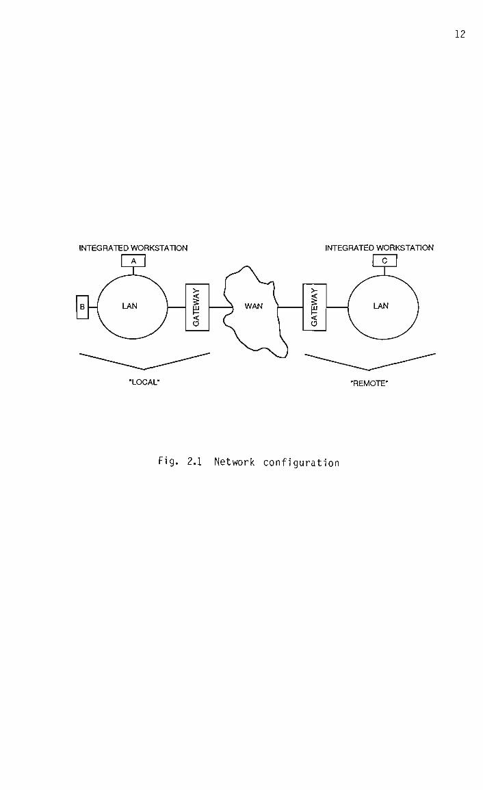
The basic network configuration considered in this thesis is shown in
Fig. 2.1. A number of integrated voice/data workstations are connected
to a local area network, enabling the transmission of voice and data
traffic among the "local" users (eg. A and B). A user outside this
local environment (eg. C) is considered to be "remote". In order to
extend communications to remote users, a gateway to a wide area network
supporting voice and data traffic is used. Since the gateway handles
all the traffic between local and remote users, it can access the WAN
by means of a single high-capacity link, as is done by current PABX
systems.
The possible inclusion of both local and wide area networks in the call
path makes the design of the voice terminal more demanding, as the two
types of network are often significantly different in terms of topo
logy, capacity, delay statistics and error rate. While the trend
12
INTEGRATED WORKSTATION INTEGRATED WORKSTATION
"LOCAL" "REMOTE"
Fig. 2.1 Network configuration

13
towards wide area networks using fast packet switching and optical
transmission will reduce the magnitude of these differences, the pro
cess of change is slow, due to the scale of the exercise, and there are
also limits to the convergence which may be achieved.
2.2.2 Switching technique
Packet switching is invariably used in local area networks, because it
is an efficient means for a number of data users to utilize a single
transmission channel. In the wider environment, circuit switching
still dominates the PSTN, due mainly to its ease of implementation.
However, as described in Chapter 1, packet switching is likely to find
increasing use in wide area networks in the future.
The fact that at least part of the overall link for voice traffic is
packet switched should be taken into account in the design of the
speech codec. The most important considerations in this respect are
that the network has the potential to provide a variable rate connec
tion between the encoder and decoder, and that any shortcomings of the
network in terms of capacity or error rate are likely to manifest as
gaps in the received speech signal, corresponding to missing packets.
By contrast, a wholly circuit switched network would provide a fixed-
rate connection, and network limitations would result in call blocking
and isolated bit errors.
2.2.3 Capacity
A fundamental assumption about the network is that the capacity of each
link is-sufficient to allow digitized speech to be transmitted in real
time. From past experience with speech coding, it can be predicted
that a bit rate of about 16 - 64 kbps will be involved [Flanagan 79].
This is not likely to be a problem in the local environment, as LANs

14
require a link capacity of at least 1 Mbps in order to support bursts
of data traffic [Tanenbaum 81].
Considering the wider environment, standard voice channels in the PSTN
are currently capable of supporting data rates up to about 10 kbps,
although higher-bandwidth connections can be made over leased lines
[Tanenbaum 81]. However, it is certain that increased bandwidth will
be available to users of future versions of the PSTN, for example as
specified in the ISDN basic- and primary-rate interfaces, which provide
respectively for 144 kbps and 2.048 Mbps of transmission capacity
[Pandhi 87].
2.2.4 Channel errors
Assuming that the interface equipment associated with a network link is
functioning correctly, bit errors can be caused in the channel by
thermal noise, interference, and signal dispersion [Tanenbaum 81]. The
error rate in a particular channel is highly dependent on the type of
transmission medium used. For example, coaxial cables are more resis
tant to electrical interference than twisted pairs [Gee 83], and local
area networks using the former typically have error rates of the order
of 1 in IO9.
While the current trend in wide area networks is towards the use of
optical transmission technology, which is highly reliable, the gradual
nature of this process means that the possibile inclusion of a low-
integrity link in the overall voice path must be considered. Error
rates up to 1 in 10"* are currently encountered in the PSTN, and this is
likely to remain true for some time to come [Maitre 82]. An extreme
type of network as regards error rate is the mobile radio network, in
which signal fading may cause average error rates of up to 1 in 10^

15
[Jayant 75]. For this reason, and because of the tight bandwidth
restrictions involved, the transmission of coded speech over mobile
radio networks is not considered in this thesis.
2.2.5 Delay
Signal delay has a deleterious effect on interactive voice communica
tions, as is discussed in detail in Chapter 3. In general, the domin
ant causes of signal delay in packet switched networks are propagation
delay and queueing delay, the latter being incurred in network nodes
(ie. switches). In order for a network to support interactive voice
communications, queueing delay should be minimized, a requirement which
makes some networks installed for data communications poorly suited to
voice traffic, an example being the ARPANET [Weinstein 83].
2.3 The workstations
2.3.1 Functional components
Each integrated workstation on the network may be considered to consist
of three functional components; a packet voice terminal associated with
voice communications, a packet data terminal associated with data
communications, and a local computing facility. While these entities
may overlap in their use of the workstation's physical resources,
distinguishing among them is conceptually useful, because this thesis
is concerned specifically with the packet voice terminal. By contrast,
the packet data terminal and local computing facility are assumed to
exist already.
2.3.2 Structure of the packet voice terminal
As the field of packet voice communications is evolving rapidly, a

16
sensible approach to the design of a packet voice terminal is to speci
fy its functions in terms of a set of independent modules with clearly
defined interfaces [O'Leary 81]. Then if one of the modules is changed
or updated, the impact on the other modules is minimized. This philo
sophy is also compatible with a fundamental aim of this project, namely
to provide a voice communications facility which is independent of the
nature of the network as far as possible.
There are three essential modules in a packet voice terminal [O'Leary
81], as shown in Fig. 2.2. The first is the speech codec, which
converts the speech signal between its analog and digital forms and
implements the coding algorithm. The second is the network voice
protocol [Cohen 78], which provides service-specific features to allow
voice communications to take place over a network. In particular, the
packetization, prioritization, flow control, synchronization and fill-
in of voice traffic are performed in this module, as is discussed in
detail in Chapter 5. The third module is the access controller, which
provides the network-specific packet transport mechanism [O'Leary 81].
The nature of the access controller, and in particular its ability to
handle prioritized traffic, can have a considerable effect on voice
communications, as is discussed in Chapter 4.
In terms of the International Standards Organization (ISO) Reference
Model of Open Systems Interconnection [Tannenbaum 81], the access
controller covers the Physical and Data Link protocol layers, and the
network voice protocol covers the Network, Transport and Session
layers. While a practical packet voice terminal will probably include
higher-level protocols as well (ie. Presentation and Application
layers), these are not considered here.
The maintenance of independence among the above three modules places

17
("•——n
i CODEC
I NETWORK VOICE PROTOCOL
I ACCESS CONTROLLER
I c NETWORK }
Fig. 2.2 Structure of the packet voice terminal

18
certain restrictions on the design of the packet voice terminal. For
example, some schemes for performing packet voice fill-in (a function
of the network voice protocol), operate on the speech signal in decoded
form. They therefore need to be implemented between the codec and the
handset, which clearly violates the structure of Fig. 2.2. A similar
observation applies to packet voice synchronization techniques which
require network-wide synchronized clocks, and therefore make special
demands on the access controller.
In the context of an integrated voice/data workstation, the packet
voice terminal is likely to share some physical resources with other
functional components, as described above. It is assumed in this
thesis that the network voice protocol is implemented on the work
station's main processor, and that the access controller is implemented
by means of dedicated hardware (eg. on an expansion card).
It is known from past experience that implementing the speech coding
algorithm on the workstation's main processor is not feasible, because
the general purpose nature of such devices leads to inefficient imple
mentations of signal processing functions. Furthermore, the processor
already has a significant load placed on it by the high-level protocol
software. For these reasons, extra hardware is required for the speech
codec and the associated codec/protocol interface.
2.3.3 Summary and conclusions
The maintenance of modularity in a packet voice terminal is an impor
tant design goal. While it precludes the use of some techniques, it is
believed that its advantage in terms of "future-proofing" is of greater
significance. However, the flexibility provided by terminal modularity
is achieved at the expense of efficiency, and in practice it may be

necessary to violate this principle in order to increase information
throughput. An example of this is described in Section 7.10, where
part of the process of packetization (which is strictly speaking a
function of the network voice protocol), is assigned to the codec.

20
CHAPTER 3 : SPEECH QUALITY IN PACKET VOICE COMMUNICATIONS
3.1 Introduction
An important measure of the performance of a voice communication system
is the subjective speech quality as perceived by the users. Other
performance issues are the service availability and the network res
ponse time [Gruber 83], but as these are not related directly to the
design of the codec, they are not considered here.
Subjective speech quality in packet communications is typically influ
enced by a number of factors, namely distortion, delay, loss and cor
ruption of the signal. In this context, "distortion" refers to deter
ministic perturbation of the signal , such as is caused by quantization,
whereas "corruption" refers to stochastic perturbations caused by chan
nel errors. In this chapter, the causes of these various degradations
are discussed, and consideration is given to their minimization.
3.2 Signal distortion
3.2.1 Introduction
The speech path in a digital communication system typically consists of
a microphone, pre-sampling filter, encoder, transmission channel, de
coder, reconstruction filter, and earphone or loudspeaker. One of the
major benefits of a digital channel is that distortion-free trans
mission over an arbitrary distance may be achieved, given sufficient
bandwidth and signal power [Taub 71]. However, practical restrictions
mean that a certain amount of signal corruption occurs in digital
channels and this issue is considered separately in Section 3.5.
In this section, signal distortion introduced by the other elements in

21
the speech path is discussed, in terms of "variable" distortion, which
is available for manipulation, and "fixed" distortion, which is not.
3.2.2 Fixed distortion
The distortion introduced by the pre-sampling and reconstruction fil
ters is essentially in the form of signal bandlimiting, and is neces
sary to control the transmission bandwidth used by the signal and to
prevent aliasing in digital systems. At present, "narrowband" tele
phony (300 - 3400 Hz) is almost universal [Jayant 84], although "wide
band" telephony (50 Hz - 7000 Hz) is likely to become of increasing
importance in the future [Mermel stein 88].
Microphones and earphones currently used in narrowband telephony
exhibit considerable non-linearity in dynamic range and non-uniformity
in frequency response, implying correspondingly large signal distor
tion, although some aspects of this distortion, such as the attennua-
tion of low-level background noise and the pre-emphasis of high
frequencies, can actually enhance speech intelligibility [Gayford 70].
While it is likely that future transducers will introduce less signal
distortion, in response to the requirements of wideband telephony
[Maitre 82], the nature of current devices should be allowed for in the
design and evaluation of a narrowband voice communications system.
3.2.3 Variable distortion
The nature and degree of the distortion introduced by the process of
encoding and decoding the signal is dependent on the coding algorithm
used. Appropriate measures of this distortion are also coder-
dependent, since some techniques attempt to preserve the perceptual
qualities of speech, while others attempt to preserve its waveform, as
is discussed in Chapter 7. Where a waveform coding technique is used,
a reasonable measure of signal distortion is the signal-to-noise ratio
(SNR) of the decoded speech. The SNR level required for speech coders
in the current telephone network is 33.9 dB [Jayant 84]. However, it
is important to note that this figure includes an allowance for up to
14 tandem encoding-decoding operations in the network. If no such
operations take place, (as is likely in a fully digital network) then
an SNR of 22 dB provides equivalent quality [Bylanski 84].
3.2.4 Conclusions
In order to maintain compatibility with current systems, it should be
assumed that standard narrowband transducers and filters are used.
Attempts to minimize the overall signal distortion should therefore be
concentrated on the speech coding algorithm.
3.3 Signal delay
3.3.1 Types of delay
It is possible to identify a number of independent components of the
total signal delay in packet switched networks. The first is the
length of time it takes to sample the input speech signal and convert
it to digitally coded form, which is known as the encoding delay.
Sufficient code words must then be accumulated to fill a packet, lead
ing to the packetization delay. While the packet waits to be transmit
ted, it incurs queueing (ie. access) delay. The time taken to clock
the packet out of the transmitter depends on the bit rate of the link,
and is known as the transmission time (or delay).
If the packet does not have to pass through any intermediate nodes in
the network, the time it takes to reach the receiver is determined

23
solely by the propagation delay. However, in a multi-link network
there will be further queueing and transmission delays associated with
each network node. Once the packet reaches the receiver, it is put
into a buffer, in which it incurs a synchronization delay before being
played out to the decoder. Finally, the process of converting the
coded speech back to analog form adds decoding delay.
For a given call path, some of the above delays are variable (eg.
queueing delay) while others are fixed (eg. propagation delay). It is
the function of the synchronization algorithm in the network voice
protocol to compensate for variable delays, which it does by intro
ducing extra synchronization delay where required, as is described in
Section 5.5. If the synchronization process is perfect, then the total
signal delay is constant for all packets.
In practice, perfect synchronization is difficult to achieve, so that
the total signal delay may still contain a degree of variability. This
implies temporal distortion of the decoded speech, the subjective
effects of which are discussed in Section 5.5.2.5. For the purposes of
the present discussion, however, it is assumed that any variable delay
the signal incurs is fully compensated for by the synchronization algo
rithm, although at the possible expense of extra fixed delay.
3.3.2 The subjective effects of fixed delay
When the fixed delay in a voice communications system is excessive,
users involved in a conversation tend to mistake the pause which occurs
while a talkspurt is propagating across the network as an indication
that the other party has stopped talking. This results in frequent
talkspurt "collisions" between the two users, and a degradation in the
quality of the service [Seidl 87]. While a "limit of acceptability"
24
cannot be defined precisely for fixed signal delay, the CCITT has
suggested that only very disciplined users who are aware of the prob
lems involved can effectively use a connection with an end-to-end delay
of greater than 300 mS [Seidl 87].
Smaller delays can also cause significant service degradation when
combined with inadequate isolation between the transmit and receive
speech paths, as delayed echoes are confusing to users if they are not
sufficiently attennuated, typically making them stutter [Tanenbaum 81].
While the electrical echoes associated with two-wire/four-wire hybrids
and other line impedance mismatches do not occur in fully digital
networks, acoustic echoes can still be introduced if there is a signi
ficant degree of acoustic coupling between the transmit and receive
paths in the remote telephone set, as in the case of loudspeaking
telephones [Seidl 87].
3.3.3 Delay minimization
In the general case, a speech path will include local and remote LANs,
as wel 1 as an intervening WAN, as discussed in Chapter 2. The signal
delay within the WAN will consist of transmission, propagation and
queueing delays. Through the use of high-capacity links and high-speed
switches, it is possible to reduce the transmission and queueing delays
in wide area networks to sub-millisecond values. However, the propaga
tion delay is constrained by the speed of light, and can be consider
able in a long-distance link, an example being the 270 mS one-way
propagation delay in a satellite link [Tanenbaum 81]. This means that
the delay incurred by the signal in the LANs should be a few tens of
milliseconds at most, so as to maintain acceptable performance for
long-distance cal1 s.

25
For a given LAN, the only delays which cannot be manipulated are the
transmission and propagation delays. Minimization of the encoding and
decoding delays requires the choice of a suitable coding technique.
Some speech coding algorithms operate on a "block" or "frame" of the
speech signal at a time, and the encoding delay hence consists of a
period during which sufficient data is acquired to fill the block
(typically about 30 mS), and a further period in which the block is
analysed (typically about 20 mS) [Seidl 87]. (However, in this case no
further packetization delay is involved, so that the effective encoding
delay is the time taken to analyse the block.)
Other speech coding algorithms operate on a sample-by-sample or
"sequential" basis, and therefore introduce an encoding delay of only
one sample period (typically 125 uS). With both block and sequential
coding techniques, the decoding delay is usually less than or equal to
the encoding delay.
Current specifications for encoding/decoding delays in interactive
voice communications over wide area networks are in the range 2 mS
[Maitre 82] to 4 mS [Mermel stein 88]. However, these requirements are
imposed primarily for echo control purposes [Mermelstein 88], and it is
likely that in a fully digital network they could be relaxed somewhat.
The packetizing delay is determined by the bit rate of the codec and
the packet length, which is a parameter of the network voice protocol.
The packet length is usually selected by trading off a number of con
flicting requirements, one of which is the requirement for a small
packetization delay, as is discussed in Section 5.2.
The queueing delay in the transmitter, (ie. the access delay), depends
in general on the nature of the access mechanism and on the prevailing

network load, which is in turn influenced by the flow control algo
rithms implemented by all workstations on the network. It is thus to
be expected that a wel 1-designed flow control algorithm will tend to
reduce the access delay.
As mentioned in Section 3.3.1, the synchronization delay is a variable
quantity introduced by the synchronization algorithm in the network
voice protocol to compensate for other variable delays in the signal
path. Minimization of this delay is thus dependent on the minimization
of the other variable delays, as well as on the design of the synchro
nization algorithm.
3.3.4 Summary and conclusions
Due to its deleterious effects on interactive communications, and the
possibility of echo-related problems, it is desirable that the total
delay between the production and reproduction of speech is minimized.
For a given network and access controller, this requires the use of a
low-delay speech coding algorithm, an appropriate voice packet length,
an effective voice/data flow control algorithm, and a wel 1-designed
packet synchronization scheme. Furthermore, the variability of the
delay encountered by packets within the network is of concern, as
variable delay must be compensated for by increased total delay if
temporal distortion of the signal is to be avoided.
3.4 Signal loss
3.4.1 Introduction
In a packet switched network, signal loss manifests as the absence at
the receiver of a portion of the code stream corresponding to the
length of one or more packets. There are in general four possible

27
causes of such "missing" packets. One possibility is that no attempt
is made to transmit a packet, because it contains code which corres
ponds to an interval of silence in the input signal. These are called
"silent" packets in this thesis, and their elimination should in theory
not detract from the perceived speech quality. The extent to which
this is true in practice is discussed separately in Section 3.6.
3.4.2 Lost packets
When an attempt is made to transmit a packet (ignoring for the moment
whether it is silent or not), there are in general three ways in which
it can become "lost". Firstly, it may be discarded at the transmitter
or at one of the network nodes, due to a temporary overload in the
associated network link. This is referred to here as a "blocked"
packet. Secondly, a packet which is not blocked may have its header
(containing address and control information) corrupted by a channel
error, with the result that it fails to reach the receiver, or is
discarded when it does so. This is called a "corrupted" packet. The
third possibility is that the packet is neither blocked nor corrupted,
but incurs so much delay in transit that by the time it reaches the
receiver it is too late to be used, and is hence a "late" packet. As
blocked, corrupted and late packets are those which are offered to the
transport network but are not delivered in a useful way, they are
referred to collectively as "lost" packets.
3.4.3 The effect of lost packets on speech quality
As lost packets may occur at any point in the speech signal, including
during talkspurts, they are expected to detract to some extent from the
overall speech quality. It is known that for PCM-coded speech a lost
packet rate of about 1 in 100 is subjectively acceptable, provided that

28
individual packets contain less than about 32 mS of speech [Jayant 81].
As a PCM system encodes each sample independently, this figure relates
only to the effect of the gaps in the decoded signal, and assumes that
the loss of a packet has no effect on subsequent portions of the
signal. However, in coding schemes which are more bandwidth-efficient
than PCM, samples are usual ly not coded independently, implying that
the effect of a lost packet will not be isolated. This means that with
such schemes attention must be given to ensuring that tracking between
the encoder and decoder is quickly re-established after packet loss
occurs.
It is also important to note that the above figure for an acceptable
packet loss rate is based on average statistics, and does not consider
the temporal distribution of lost packets or their relative perceptual
importance. For example, the loss of two successive packets is likely
to be more disturbing than if the packets are widely separated. In
general, it is possible to manipulate the probability that a packet
will be blocked or late by altering its transmission priority relative
to that of other traffic. This can take place either in the access
controller, as is discussed in Chapter 4, or in the network voice
protocol, as is discussed in Chapter 5. The effect of lost packets on
perceived speech quality also depends on the way in which gaps in the
packet stream are filled in at the receiver, as is discussed in Chapter
5.
3.4.4 Summary and conclusions
Gaps in the received packet stream due to lost (blocked, corrupted or
late) packets are expected to have a more severe effect on speech
quality than those due to silent packets. While packet loss caused by

29
channel errors is unavoidable (in the absence of error correction), it
is possible to minimize the incidence of blocked and late packets by
means of appropriate flow control and synchronization algorithms.
Furthermore, the effect of such gaps on speech quality can be reduced
by means of suitable voice prioritization and packet fill-in algo
rithms.
3.5 Signal corruption
3.5.1 Introduction
Bit errors in the transmission channel can corrupt either the header or
the information field of a voice or data packet. There are three
possible responses to this situation. Firstly, it can be assumed that
errors are sufficiently infrequent as to be insignificant, so that the
possibility of a packet being corrupted is ignored. Secondly, corrupt
ed packets can be identified by means of error-detecting codes [Tanen
baum 81], after which they are simply discarded. Thirdly, errors can
be corrected, either by requesting that corrupted packets are retrans
mitted, or through the use of error-correcting codes [Tanenbaum 81].
A minimum requirement in any packet switched network is that errors in
the packet header are detected, in order to ensure that the packet is
not delivered to the wrong destination. In the case of a data packet,
it is also required that errors in the header or information field are
corrected. Due to the relatively low error rates of the majority of
data networks, this is most efficiently done by means of retransmission
[Tanenbaum 81].
3.5.2 Corruption of voice packets
The retransmission of a corrupted voice packet is undesirable because

30
of the extra delay incurred. A packet with a corrupted header will
therefore be discarded at some point in the network, so that the packet
is "lost" as far as the receiver is concerned, as discussed in Section
3.4.
If only the information field is corrupted, it is usually better to
make use of the packet than to discard it, as the robustness of the
speech perception mechanism means that errors in the decoded signal are
tolerable. While error-correcting codes can be used to remove errors
in the information field, the extra processing and bandwidth associated
with such codes means they are only worthwhile with very low-integrity
channels such as in mobile radio networks [Natvig 88].
The effect of corruption of the speech code on the decoded signal will
depend on the coding technique used and the way in which the code is
formatted, as is discussed in detail in Section 7.8. However, of
particular concern is the case where the coding algorithm is adaptive,
as it is then possible that a single bit error will cause a decoder
error which persists indefinitely, unless special provision is made in
the coding algorithm itself for the effect of bit errors to be dissi
pated with time [Goodman 75].
Apart from the actual speech code, there may also be "side information"
in the packet information field, such as a quantizer step size or
predictor coefficient, which can be used to assist the decoder in
recovering from packet loss. As the decoder is likely to be more
sensitive to the corruption of this side information than of the speech
code itself, limited forward error correction might be applied in this
case. As a minimum requirement, errors in the side information should
be detected, so that it can be ignored if it is corrupted.

31
3.5.3 Summary and conclusions
Error correction by re-transmission is not appropriate for voice traf
fic, and should therefore not be implemented by the low-level protocols
of a network used for interactive voice communications. Forward error
correction is also not applicable in general, although it may in some
cases be applied to small portions of the information field. It is
therefore important that the decoder itself is able to recover from the
effects of speech code corruption.
3.6 Silence elimination
3.6.1 Introduction
The detection and elimination of silence from the transmitted signal in
a packet voice network represents a special case of signal loss, as
considered in general in Section 3.4. In theory, silence elimination
should not have a noticeable effect on perceived speech quality, as
long as appropriate inter-talkspurt pauses are reconstructed at the
receiver. In practice, there may be significant direct effects on
speech quality, as considered below, as well as indirect effects, as
are discussed in Chapter 5 in the context of packet synchronization and
fill-in.
3.6.2 The advantage of silence elimination
Silence elimination offers a potential bandwidth saving of up to about
50% in packet voice networks [Forgie 76]. In the somewhat unrealistic
case of a voice-only packet switched network, realization of this
saving requires that 40 or more conversations are in progress at a
given time, in order to allow the statistical multiplexing of indepen
dent signals to be effective [Forgie 76]. While this requirement can
32
be relaxed through the queueing of voice traffic [Weinstein 79], this
has the undesirable effect of increasing the signal delay.
By contrast, in an integrated voice/data network, the less stringent
delay requirements of data traffic mean that it can be queued in order
to aid the multiplexing process, with the result that the increase in
total traffic throughput associated with silence elimination is realiz
able with fewer than 40 conversations [Forgie 76].
3.6.3 The disadvantages of silence elimination
The process of discriminating between talkspurts and silence is common
ly known as Speech Activity Detection (SAD) [Weinstein 83], and one
disadvantage of silence elimination is the potential degradation of the
speech signal caused by the non-ideal operation of practical SAD de
vices [Seidl 87]. Traditional SAD algorithms discriminate between
talkspurts and silence on the basis of a measurement of the short-term
signal energy [Drago 78]. More sophisticated schemes which make use of
other signal characteristics, such as the signal's zero-crossing rate,
have also been proposed, with corresponding increases in algorithmic
complexity and processing delay [Un Aug. 80].
There are two types of "mistake" which a SAD algorithm can make, namely
to erroneously reject a portion of a talkspurt, and to erroneously
accept silence. The first type of mistake typically manifests as the
clipping of the front-end or tail-end of a talkspurt, which may be
difficult to distinguish from background noise due to its low energy
[Drago 78]. Unfortunately, these portions of talkspurts are often
perceptually important, particularly low-energy consonants such as the
"s" in "stop" [Drago 78].
This problem is exacerbated by high levels of background noise, and by
33
any mismatch which may exist between the long-term signal energy and
the decision threshold of the SAD algorithm, although an improvement
can be obtained in such cases through the use of adaptive energy
thresholds [Drago 78]. (Long-term energy mismatch can be caused by
changes in the parameters of analog portions of the speech path, eg.
transducers, transmission lines and amplifiers, as well as by the
varying loudness of speech from different speakers).
The erroneous rejection of portions of talkspurts by simple energy-
based SAD algorithms can also be improved by introducing "hangover"
periods, which keep the SAD output in the active state for a short time
(typically about 250 mS [Drago 78]) after the end of a talkspurt is
indicated by the short-term energy calculation. A similar technique
can be used to allow anticipation of the commencement of a talkspurt,
although this requires an appropriate degree of buffering in the trans
mitter, and consequent extra delay [Weinstein 83].
The second type of SAD error, involving the acceptance of a portion of
a silence interval, is not detrimental to the intelligibility of
speech, but can nevertheless be subjectively annoying. With this type
of error, the "silence", which is in practice low-level background
noise, is transmitted, and because it is often different in nature from
the artificial silence which is generated by the receiver to fill in
for missing packets, it is more noticeable to the listener than would
have been the case if the connection were continuous [Forgie 76].
Final lyi the overall effect of silence elimination in a speech communi
cation link is a loss of "subjective transparency" [Derby 87]. During
talkspurts, the listener is usually aware to some extent of background
noise in the speaker's environment. Depending on the fill-in strategy

34
used in the receiver, this noise either ceases or is replaced by random
noise during silent intervals. Whether this is perceived as a loss of
subjective transparency depends on the level of background noise, and
how well the fill-in noise matches it [Dvorak 88].
In recognition of this problem, it has been proposed that a few packets
of background noise be transmitted at the end of each talkspurt, and
that at the receiver these packets be played out with gradually increa
sing attennuation, thereby fading the noise into silence [DeTreville
83]. While this strategy is reported to be effective in an "office"
environment, it is not known whether it will be sufficient in more
noisy environments.
Also of concern is the case where the conversation is suspended for a
time (such as when one user puts down the handset in order to perform
some task). If silence is eliminated from the speech signal, the other
user is left with a "dead" connection. Although a solution to this is
for the user who puts down the handset to put the other "on hold" until
the conversation is resumed, this requires a degree of user discipline,
and is arguably less friendly than the maintenance of an open connec
tion.
3.6.4 Summary and conclusions
While bandwidth saving has traditionally formed a strong incentive for
eliminating silence from packet voice communications, it is believed
that this is outweighed by the perceptual disadvantages when trans
mission bandwidth is not at a premium. Furthermore, the on/off
approach to speech transmission does not take full advantage of the
ability of a packet switched network to provide a truly variable rate
connection.
35
For example, low bit rate transmission of silence can be implemented
straightforwardly on such a network. Apart from the improvement in
subjective transparency this offers, it also means that any mistake
made by the SAD algorithm is likely to have a relatively minor percep
tual effect, since it will merely cause a change in coding rate (and
hence in speech quality), instead of affecting the continuity of the
transmitted signal. Such a scheme also has advantages for the synchro
nization and fill-in of voice packets, as is described in Chapter 5.
3.7 Overall speech quality
3.7.1 Quality standards
The subjective quality of digitally coded speech is usually described
in terms of four broad categories, namely broadcast, toll, communica
tions, and synthetic quality [Flanagan 79]. Broadcast quality speech
has a bandwidth (7 kHz or more) which is wider than that currently
associated with telephony. Toll quality speech is accepted as standard
for commercial telephony, and is indistinguishable in terms of signal
distortion from undigitized speech which has been correspondingly band-
limited [Jayant 84].
Communications quality speech, by contrast, contains detectable distor
tion, but suffers from very little degradation of intelligibility.
Finally, synthetic quality speech is characterized by substantial loss
of "naturalness", which may not be a disadvantage in person-machine
transactions [Gold 77], but is unnacceptable in person-to-person commu
nications in which factors such as speaker recognition are important.
It is important to note that standards for digital speech quality have
until recently been dominated by the characteristics of the current

36
PSTN (ie. analog transmission, fixed bandwidth connections, circuit
switching). With the increasing use of Digital Circuit Multiplication
(DCM) equipment and the advent of packet switched voice communications,
it has become necessary to take account of forms of degradation pecu
liar to such systems, such as sample (or packet) loss, variable delay,
and the effects of variable rate coding. A subjective testing methodo
logy for such systems is currently under development by the CCITT
[Dvorak 88].
3.7.2 Maximizing the overall speech quality
In principle, it is possible to trade the various factors affecting
speech quality in packet voice communications off against each other.
For example, packet loss due to network congestion can be avoided by
reducing the bit rate (and hence possibly increasing the distortion) of
the coded speech. Alternatively, for a given bit rate, the incidence
of packet loss due to momentary link overload can be reduced by
increasing the maximum lengths of queues in the network (and hence
increasing the average signal delay). As another example, signal
corruption can be reduced by means of forward error correction, at the
expense of increased network load.
A rigorous approach to the design of a packet voice communications
system would thus attempt to maximize the overall subjective speech
quality by finding an optimal compromise among the above degradations.
However, this is difficult to do in practice because the various types
of degradation interact with each other. For example, it has been
found that when the signal distortion is low (as in 64 kbps PCM
coding), subjective quality is affected more by increased packet loss
than by increased signal delay, whereas for higher signal distortion
(as in 32 kbps Delta Modulation coding) the reverse is true [Aoki 86].

37
Furthermore, performing formal subjective tests for incremental changes
in each type of degradation is impractical.
Another issue is that because the causes of degradation are distributed
across the network, it is not possible to apply accurate control at any
single point. For example, the transmitter does not know in general
how long a packet will take to reach the receiver, implying that it
cannot make an accurate trade-off between packet loss and signal delay
by extending its transmit queue length. (However, this trade-off can
be made at the receiver, by appropriate manipulation of the receive
buffer length, as is described in Section 5.5.) Similarly, the trans
mitter does not know in advance how many packets will be discarded by
"downstream" network nodes due to local congestion conditions, and thus
cannot make an accurate trade-off between the signal coding rate and
the packet loss rate.
3.7.3 Conclusions
Due to the practical problems involved in a rigorous trade-off among
the various types of quality degradation in a packet switched network,
it is necessary to adopt a pragmatic design approach. Specifically,
fixed target levels are set for most of the forms of degradation, and
an attempt is then made to minimize the remaining degradations. Thus
if the packet loss rate is constrained to be less than 1 in 100, the
total signal delay (excluding propagation delay) less than 50 mS, and
the channel bit error rate less than 1 in 103, then speech quality can
be measured in terms of the signal distortion.
38
CHAPTER 4 : THE ACCESS CONTROLLER
4.1 Introduction
In a packet switched local area network, it is necessary for access to
the transmission channel to be re-negotiated for each packet in a call,
and this is done by the access controller shown in Fig. 2.2. As the
terminals connected to the LAN usually compete for the use of the
channel on a distributed basis, the problem of access control is
frequently complex [Kurose 84].
It is assumed in this thesis that access multiplexing is performed by
means of statistical time division. This approach, which is used in
the majority of existing data LANs, implies that in general packets do
not get instant access to the channel, and have to wait for some period
(which may be fixed or variable) until the channel is available. An
alternative multiplexing technique uses "spread spectrum" modulation,
which can avoid access delay at the expense of variable SNR in the
received signals [Kahn 78].
4.2 Contention-based access vs. ordered access
While many distinct access control schemes have been proposed for local
area networks [Kurose 84], it is possible to identify two generic
types. The first is the "ordered" or "controlled" access type, an
example being token passing, which is used in the Token Ring [Gee 83].
The second is the "contention-based" or "random" access type, an ex
ample being Carrier Sense Multiple Access with Collision Detection
(CSMA/CD), which is used in the Ethernet [Gee 83].
A characteristic of contention-based access schemes is that the access

39
delay is not bounded (ie. it cannot be guaranteed that a particular
packet will be successfully transmitted within a given time period.)
This is not a major problem for most data traffic, but is clearly of
concern when the packet contains coded speech, which must meet real
time end-to-end delay constraints. In practice, voice packets which
experience excessive access delay will be discarded at the transmitter,
and hence lost.
By contrast, an upper bound can be defined for the access delay of a
particular packet when an ordered access technique is used. (Whether
or not this upper bound will be acceptable to voice traffic is another
issue.) As might be expected from these considerations, it has been
found that token passing results in better voice performance than
CSMA/CD in an integrated voice/data network [DeTreville 84]. Neverthe
less, the relative ease of implementation of contention-based access
schemes has resulted in their wide proliferation in data LANs.
4.3 Priority access
In addition to discriminating between ordered and contention-based
access techniques, it is possible to make a distinction between those
which support prioritized traffic, and those which don't. The former
type typically refrain from accessing the channel if they do not have
packets of a sufficiently high priority to transmit, thereby making
bandwidth available to other workstations which have more important
traffic. For example, if voice data is given a higher access priority
than data traffic in an integrated network, then the variable delay
incurred by voice packets will be reduced, regardless of whether an
ordered or a contention-based access technique is used.
However, as far as this thesis is concerned, it is important to note

40
that a large number of currently installed data LANs (in particular
Ethernet LANs), do not support priority access. This means that it is
not possible to guarantee the continuity of voice calls on these LANs,
particularly under adverse channel conditions, such as during bulk data
transfers. Nevertheless, it is likely that it will be possible to
reduce the incidence of call interruptions to an acceptably low level,
by means of suitable flow control measures applied to both voice and
data traffic.
4.4 Summary and conclusions
In order to allow the speech codec and network voice protocol to be
used with a variety of local area networks, restrictive assumptions
should not be made about the access controller associated with the
network. In particular, the possibility of voice packets incurring
variable, and in some cases unacceptably high access delays should be
considered. This implies the need for packet voice synchronization and
fill-in algorithms in the network voice protocol, and these are dis
cussed in Chapter 5. In addition, the effect of excessively delayed
(ie. lost) packets on the codec must be considered, and provision made
for tracking between the encoder and decoder to be recovered.
Furthermore, it should not be assumed that priority access to the
channel is supported by the access controller. This means that atten
tion must be given to the identification and isolation of the most
important portions of the coded voice signal, so that the impact of
adverse channel conditions on voice communications is minimized. This
issue is discussed in detail in Chapters 5 and 7.
41
CHAPTER 5 : THE NETWORK VOICE PROTOCOL
5.1 Introduction
The network voice protocol utilizes the network and access controller
to provide a real-time voice communication facility. It has two main
tasks, namely to establish/disconnect a call, and to maintain a call
which is in progress [Cohen 78], [O'Leary 81].
In order to establish a call, the network voice protocol must interact
with the user to obtain the number of the callee. It must then asso
ciate this number with the physical address of a workstation, and
negotiate the setting up of the call with the network and workstation
concerned. At the end of the call, disconnection must be similarly
negotiated. It is also necessary that audible signalling tones (dial
ling, ringing and busy) be conveyed to the user at various stages of
the above process, and the generation of these tones impacts on the
codec design, as is considered in Chapter 6.
As regards call maintenance, the network voice protocol in the trans
mitter must packetize, prioritize and flow control the coded speech.
In the receiver, it must depacketize the speech, synchronize its play-
out, and fill in any gaps caused by missing packets. As many of these
functions of the network voice protocol have a significant effect on
the design of the speech codec, they are considered in detail below.
5.2 Packetization
5.2.1 Introduction
The process of packetization involves collecting a suitable amount of
coded speech, formatting it into the information field of a packet, and

42
appending a packet header containing addresses and control information.
Depacketization reverses this process to produce the original coded
speech. A fundamental issue in this context is the choice of the size
of the packet information field, or equivalently, the total packet
length for a given header length.
5.2.2 Factors influencing the optimum packet length
Overall signal delay is an important factor which influences the choice
of the length of voice packets. Increasing the packet length reduces
the packet production rate, thereby reducing the delay incurred in
network nodes in processing each packet [Suda 84]. On the other hand,
increasing the packet length increases the packetization delay, for a
given coding rate. This means that minimization of the overall delay
involves trading these delay components off against each other [Minoli
79].
Also of importance is the fact that increasing the packet length for a
given coding rate increases the audibility of gaps in the decoded
speech caused by missing packets [Jayant 81]. Finally, decreasing the
packet length decreases the bandwidth efficiency of the packetization
process, since the proportion of the total packet length consumed by
the packet header increases. In practice, an upper bound is placed on
the packet length by delay and loss-perception issues, while a lower
bound is defined by efficiency considerations.
5.2.3 Instantaneous variations in the packet length
Given that the conditions prevailing in a network vary dynamically, it
has been proposed that the packet length should be adapted accordingly.
In one such scheme [Gonsalves 82], an attempt is made to transmit a
43
packet once it contains a reasonable amount of information. During an.y
delay incurred in the process of transmission, the packet grows in
length, up to a specified maximum. If the packet still has not been
transmitted when the maximum length is reached, its contents are
managed as a FIFO queue, the oldest information being discarded when
new information becomes available.
The main benefits of this scheme are that it reduces the total delay in
the transmitter by effectively overlapping the packetization and access
delays, thereby avoiding the discarding of packets due to excessive
access delay. It also transmits fewer packets under heavy load, there
by applying a degree of negative feedback [DeTreville 84]. However,
satisfactory synchronization of a stream of variable-length packets can
only be achieved at the receiver at the expense of extra synchroniza
tion delay, in order to prevent the receiver running out of code for
playback when a short packet is followed by a long packet. In addi
tion, the fact that the packet length in the above scheme is not set
until the time of transmission means that it must be implemented in the
access controller itself, rather than in the network voice protocol.
5.2.4 Long-term variations in the packet length
It is also possible to adapt the packet length to long-term changes in
the network conditions. As described in Section 5.2.2, minimization of
the total packet delay involves a trade-off between the packetization
delay and the nodal queueing delay, so that if the queueing delay
increases significantly due to congestion, the use of longer packets is
indicated. In order to avoid the possible synchronization problems
described in the previous section, the packet length can be adapted
gradually. Another possibility is to determine an appropriate packet
length at the beginning of a call, and keep this fixed for the call's

44
duration.
5.2.5 Summary and conclusions
A significant implication of the above discussion is that the codec
should allow flexibility in the choice of the packet length. In block-
oriented speech coding techniques, the encoder collects a number of
input samples and analyses them before producing the output code. This
means that the total encoding delay (ie. collection + analysis) is
considerable, typically about 50 mS [Seidl 87]. However, if the packet
length is made equal to an integral number of block lengths, then there
is no need for further delay to be incurred by the packetization pro
cess, as mentioned in Section 3.3.3. Nevertheless, the need to relate
the packet and block lengths to each other in this case increases the
degree of dependence between the codec and the network voice protocol.
By contrast, with sequential coding techniques each input sample is
encoded immediately, so that no constraints are placed by the codec on
the packet length chosen by the network voice protocol (or the access
controller). However, in order to obtain this benefit in practice, it
must be ensured that control information produced by the codec (such as
an indication of speech activity), is also produced sequentially,
rather than for a block of samples at a time.
5.3 Prioritization
5.3.1 Introduction
The traffic prioritization algorithm in an integrated voice/data termi
nal should attempt to maintain acceptable speech quality by identifying
the relative importance of traffic before it is offered to the flow
control algorithm. As described in Chapter 3, there are four fundamen-

45
tal causes of speech quality degradation in packet switched networks,
namely signal distortion, delay, loss, and corruption, and these can be
manipulated by the prioritization algorithm in order to maximize the
overall perceptual quality.
In particular, signal distortion can be controlled by adjusting the
coding rate according to the activity of the signal, signal delay can
be controlled by suitable prioritization of competing data traffic, and
signal loss can be controlled by prioritizing the signal according to
its transmission history. These distinct aspects of the prioritization
algorithm are discussed below.
5.3.2 The relative prioritization of voice and data
It is usually easy for voice traffic from a particular workstation to
be given priority over data traffic originating in the same work
station, but it cannot be assumed in general that an access controller
is available which wil 1 give voice traffic priority over data traffic
from other workstations. The best that can be done in this case is to
provide voice traffic with "quasi-priority", meaning that flow control
is applied to data traffic at a lower network load than for voice
traffic, thereby making network capacity available (on a statistical
basis) for use by voice traffic from any workstation. While this
policy is likely to lead to a reduction in the peak data rate offered
to each user, it is unrealistic to expect that a voice service can be
added to a data LAN with no impact whatsoever on data performance.
53.3 Prioritization of voice according to its activity
If high-activity portions of the speech signal are given priority over
low-activity portions, then in principle a saving in the average bit

46
rate required by the voice traffic can be obtained with no perceptible
quality degradation. If it becomes necessary to reduce the channel
bandwidth used by the voice traffic due to network congestion, then
identification of the relative importance of different portions of the
signal will also ensure that rate reduction has the minimum impact on
speech quality.
In practice, the success of this approach will depend on the accuracy
with which the activity of the signal is estimated. The simplest
activity estimate classifies the speech signal into talkspurts and
silence, the implication being that talkspurts should be transmitted
and silence discarded. However, as a packet switched network offers a
truly variable rate transmission service, more refined levels of acti
vity classification can be used, with potentially better results.
53.4 Prioritization of voice according to its transmission history
A performance measure often used in studies of packet voice trans
mission is the percentage of voice packets lost due to excessive delay
[DeTreville 84], [Gonsal ves 82]. However, this measure gives no indi
cation of the temporal distribution of lost packets. This factor is
likely to have a significant effect on speech quality, as the loss of
two successive packets is equivalent to the loss of a single larger
packet, and it is known that the probability of losing an entire speech
phoneme increases rapidly for packet periods greater than 20 mS [Jayant
81]. It is therefore desirable that the loss of successive packets be
avoided by prioritizing the voice traffic according to the degree of
success of previous packet transmission attempts.
A generalization of this principle is possible in the case of variable
rate speech coding, as it is reasonable to suppose that a momentary

47
reduction of the transmitted bit rate due to channel congestion will be
less noticeable than a sustained reduction. It is thus indicated that
the prioritization algorithm should maintain a record of the degree of
transmission success achieved by recent packets in a particular call,
and prioritize succeeding packets accordingly.
5.3.5 Summary and conclusions
The relative prioritization of voice and data traffic, and the priori
tization of voice traffic according to its transmission history, are
expected to have significant effects on speech quality in packet voice
communications. However, these are not of direct concern in the design
of the codec, in contrast to the relative prioritization of different
portions of the speech signal according to its activity.
The modular structure of the packet voice terminal in Fig. 2.2 indi
cates that the network voice protocol has access to the speech signal
in its coded form only, from which it may be difficult to derive
prioritization information. However, assigning the prioritization
function entirely to the codec is undesirable, because it increases the
dependency of the network voice protocol on the codec. For example, if
the codec simply tags "silent" portions of code [O'Leary 81], then the
network voice protocol can only use an "on/off" prioritization strate
gy. A more flexible approach is for the codec to supply suitable side
information to the network voice protocol to allow it to prioritize the
speech as it chooses, and with a minimum of effort.
5.4 Flow control
5.4.1 Introduction
The objective of network flow control is to regulate the entry of
48
traffic into a network in order to avoid congestion [Bially Mar. 80].
Data traffic is usually flow controlled by delaying its transmission,
ie. queueing it. If the queues become too long, fundamental corrective
action must be taken, typically involving a reduction in the rate at
which the source of the traffic (such as a disk drive) produces infor
mation. In the case of voice traffic, however, flow control by means
of queueing is undesirable, as it introduces extra signal delay. Fur
thermore, reducing the information rate of the source by requiring the
user to speak more slowly is clearly not acceptable, so that alterna
tive approaches must be used, as described below.
5.4.2 Flow control of voice traffic
Flow control has traditionally been performed in voice communications
networks by means of blocking. In the case of new calls, the user is
required to wait until bandwidth is available, and in the case of
momentary channel overload during calls in progress, excess demand is
simply "frozen out", implying loss of speech [Weinstein 79]. Both of
these manifestations of the blocking policy are unfriendly to the user,
and motivate for a more refined flow control scheme.
Fortunately, the robustness of the speech perception mechanism means
that a slight reduction in signal quality does not significantly impair
its intelligibility. This means that it is possible to flow control
voice traffic by reducing the coding rate (and hence probably increas
ing the signal distortion) when the network is congested. This princi
ple can be applied to the control of access to the network by new users
as wel 1 as to the control of rapid statistical variations in the traf
fic of calls in progress [Bially Mar. 80], although it will still be
necessary to block new calls at a certain level of congestion.

49
5.4.3 Network load estimation/prediction
In order for effective flow control to be implemented by the network
voice protocol, it must be provided with some quantity correlated with
the current network load, such as the delay experienced by previous
packets in gaining access to the channel. This quantity can then be
used to estimate or even predict the network load on a statistical
basis, so that appropriate flow control action can be taken before
network congestion has time to degrade the voice service [Johnson 81].
Prediction is possible in this case because it is expected that the
load in an integrated voice/data network will not vary arbitrarily with
time. Rather, because the average talkspurt duration is much greater
than the typical packet generation time, and because of the long hold
ing time of individual voice calls, there will be some short-term
correlation in successive measures of the level of voice traffic on the
network [Johnson 81]. Furthermore, while data traffic is inherently
less structured than voice traffic, queueing in network nodes will tend
to give data traffic Markov characteristics, thereby increasing the
predictability of the overall network load.
5.4.4 Summary and conclusions
Flow control ling voice traffic by means of queueing or blocking is
undesirable. A better strategy involves the reduction of the speech
coding rate in response to network congestion, requiring that a var
iable rate coding technique is implemented in the codec.
5.5 Synchronization
5.5.1 Introduction
The function of the packet voice synchronization algorithm in the
50
receiver is to establish a suitable playout time for each received
packet. This requires not only that the variable delay incurred by
each packet in traversing the network is accounted for, but also that
missing packets, and packets which arrive out of order, are identified.
As a number of disparate packet voice synchronization schemes have been
described in the literature [Montgomery 83], an attempt is made below
to identify the essential problems in this area, and to categorize the
solutions adopted.
5.5.2 Essential issues in packet voice synchronization
5.5.2.1 Packet ordering
In general, a packet switched network may deliver voice packets to the
receiver in a different order from that in which they are transmitted.
This can occur if the route taken by successive packets through the
network varies with time (eg. when adaptive routing is used as a means
of controlling congestion). The traditional solution to this problem
is to place a sequence number in each packet prior to transmission
[Weinstein 83]. The sequence number is incremented every time a packet
is transmitted, so that the receiver can determine the correct packet
ordering by examining successive packet sequence numbers.
It is reasonable to assume in this application that mis-ordering of
packets by the network never occurs. Obviously, this assumption holds
within LANs, which have only one possible transmission route. Further
more, a strong trend in packet switched wide area networks for real
time services is towards the use of packet virtual circuits, which also
maintain packet ordering [Burgin 87]. Nevertheless, packet sequence
numbers are still of value, as they can be used to detect missing
packets, and to distinguish among the various types of missing packet

51
described in Section 3.4.
5.5.2.2 Identification of the type of a missing packet
It is useful if the synchronization algorithm is able to detect the
cause of a potential gap in the played out speech, ie. whether it is
due to a silent or lost packet, as this information may be used by the
packet fill-in algorithm to generate an appropriate substitute packet,
as is described in Section 5.6. The synchronization algorithm should
also be able to discriminate between "on-time" and late packets, as
late packets must usually be discarded.
If silence is eliminated from the transmitted packet stream, then
packet sequence numbers are required if silent packets are to be de
tected unambiguously at the receiver [Weinstein 83]. In this case, the
packet sequence number is only incremented when a packet is actually
transmitted, ie. it is unchanged during silence intervals. Therefore,
a gap at the receiver between two packets with successive sequence
numbers must be due to one or more silent packets. Conversely, a
missing sequence number indicates a lost rather than a silent packet.
However, it is important to note that discrimination between lost and
silent packets can only be performed in retrospect, ie. once the packet
after a missing one has arrived. This may imply that extra delay must
be introduced at the receiver, which is undesirable. If silence is not
eliminated from the transmitted packet stream, then the above process
of discrimination is unnecessary.
Discrimination between on-time and late packets is also required, as
failure to do so will result in late packets being played out as if
they were on time, and the resulting temporal distortion of the signal
52
rma^ is likely to be objectionable [Forgie 76]. If explicit timing info
tion is included in the packet header, then this may be used to detect
late packets. In the absence of such information, packet sequence
numbers must be used for this purpose, as late packets cannot be de
tected unambiguously by observation of the packet arrival times alone,
due to the possibility that packets may be blocked or corrupted.
5.5.2.3 Correction of variable packet delay
The total network delay Dn suffered by a packet consists of a fixed
component Df (due to transmission and propagation delays) and a vari
able component Dv (due to queueing delays). Variations in the value of
Dv associated with successive packets result in temporal "jitter" in
the packet stream. If not accounted for, this jitter leads to the loss
of portions of the reconstructed signal, and the introduction of arti
ficial gaps. Both of these phenomena degrade the perceptual quality of
the signal, and should therefore be prevented from occurring as far as
possible. This requires that packets are buffered in the receiver prior
to being decoded, in order to smooth out jitter in the packet stream.
Fig. 5.1 shows a generic Probability Density Function (PDF) for the
network delay in packet switched networks [Aoki 86]. The tail on the
left of the distribution is truncated because packets must incur at
least some fixed delay Df. However, the tail on the right may in
general have an asymptotic form, due to the possible presence of a
number of queues of varying length in the call path. It is undesirable
to wait for the arrival of late packets falling into this region of the
distribution, as this would result in excessive overall delay. Such
packets are therefore considered lost as far as the playout of speech
is concerned.

A
D
Delay D n
D v.th
Fig. 5.1 Generic packet delay distribution
54
It is well known from listening tests that a lost packet rate of 1 in
100 or less is acceptable [Forgie 76], [Jayant 81]. This means that a
threshold of acceptability, DVj t h can be defined in Fig. 5.1 such that
the shaded area represents a cumulative probability of 0.01.
A fundamental goal of the synchronization algorithm is to maintain a
continuous playout of speech. This means that if a packet incurs an
unusually small delay (ie. less than the median in Fig. 5.1), it should
not be played out immediately, as it would then be likely that a gap
would be introduced into the decoded speech at a later stage. Rather,
the packet should be delayed by an additional amount Ds, (the synchro
nization delay) where:
Ds = Dv,th - Dv (5.D
which gives a probability of 0.99 that subsequent packets will arrive
in time to allow a continuous playout.
In practice, there are two problems associated with the implementation
of the above strategy. The first is that the delay PDF is in general
not known when a call is established. This is because unknown networks
(with unknown delay characteristics) may be included in the call path,
and these characteristics may also change with time as the network
loads change. The result is that Dv t^, ie. the delay threshold which
will include 99% of all packets, is not known in equation (5.1). The
second problem is that it is often difficult for the receiver to deter
mine the delay associated with a particular packet, implying that Dv in
(5.1) is also not known. Practical synchronization schemes therefore
usually involve imperfect estimates of Dv tn or Dv (or both).
55
5.5.2.4 Clock frequency matching
The fundamental timing references in a packet voice communications
system are the encoder and decoder sampling clocks, since these deter
mine the rate at which packetized speech code is offered to and demand
ed from the network. All operations of the synchronization algorithm
should therefore be referenced to the codec sampling clock, and this
would ideally be derived from a network-wide master source. For exam
ple, in a LAN with a bit-synchronous channel, the sampling clocks can
be derived from the channel clock [Anido 87]. However, this is often
not possible in more general networks, and the installation of special
lines for the distribution of the clock signal is usually impractical
[Montgomery 83].
It is therefore more usual to assume independent crystal-control 1 ed
sampling clocks in the packet voice terminals, which are typically
accurate to 1 part in IO5. A problem in this case is that any differ
ence in frequency between the clocks in the transmitter and receiver
will manifest as an increasing relative phase drift (up to 72 mS per
hour in the above example). Whether this represents a problem in
practice depends on the way in which the synchronization algorithm
responds to such changes, as is discussed in Section 5.5.3.
5.5.2.5 Temporal distortion of silence intervals
If silence is eliminated from the stream of transmitted packets, then
it is in general necessary to re-synchronize the packets in each talk
spurt. This is of no consequence to synchronization schemes which know
exactly how much delay each packet has incurred (these schemes are
discussed in Section 5.5.3.2). However, when this information is
approximate (Section 5.5.3.3), or not available at all (Section

56
5.5.3.4), then each packet is typically synchronized relative to the
preceding one, which clearly presents a problem in the case of the
first packet in a talkspurt. The result is that the silence intervals
between talkspurts tend to become distorted in length [Suda 84].
The perceptual importance of accurately reconstructing silence inter
vals is a subject of ongoing research. One study claims that modifica
tion of the lengths of silence intervals by up to 50% is acceptable
[Webber 77]. More detailed studies note that distortion of the rela
tively long silence intervals between sentences and phrases is less
noticeable than for intervals between words and syllables [Gruber 81],
[Gruber 85]. This is one reason for using a relatively long hangover
period (about 200 mS) in speech activity detectors, to ensure that
short silence intervals are not eliminated.
5.5.2.6 Adjustment of the playout rate
Most packet synchronization schemes assume that the decoder empties the
receive buffer at a constant rate, or at least at a rate which is
independent of the buffer occupancy, implying that the synchronization
algorithm must control buffer overflow and underflow conditions by
discarding or inserting packets of code as necessary. However, it is
also possible to adjust the rate at which the decoder operates accord
ing to the buffer occupancy [Gold 77], in a manner analogous to the
control of the encoding rate according to the occupancy of the transmit
buffer [Dubnowski 79]. In general, this strategy cannot be implemented
by simply altering the sampling rate of the decoder, as this will
change the pitch of the decoded speech. Instead, vocoder techniques
must be used, which allow the duration of a speech sound to be in
creased or decreased, without altering its pitch [Gold 77].

57
5.5.3 A taxonomy of packet voice synchronization schemes
5.5.3.1 Introduction
As mentioned in Section 5.5.2.3, an issue common to most packet voice
synchronization schemes is that Dv tn in equation (5.1) is not known in
advance for a general call path. However, there are significant diff
erences among synchronization schemes as regards their knowledge of Dv
in (5.1), and accordingly they are classified below on this basis.
5.5.3.2 Synchronization schemes with exact knowledge of Dv
There are essentially two ways in which the receiver can obtain exact
knowledge of the network delay experienced by a particular packet. In
the first, the transmitter and receiver maintain clocks which are
phase-synchronized, or equivalently, both have access to a network-wide
master clock. The transmitter places a time stamp into each packet
immediately prior to transmission, and the receiver can then compare
this stamp with its own clock when the packet is received, thereby
obtaining an exact delay measurement (in the absence of channel bit
errors).
This is known as the "absolute timing" technique [Montgomery 83]. Its
main disadvantage is that the requirement for perfectly synchronized
transmitter and receiver clocks or a network-wide master clock is often
difficult to satisfy in practice, particularly when the network covers
a wide area.
The second technique measures the variable delay suffered by a packet
at the point where it actually occurs (for example in a queue in a
network node), and then places this "delay stamp" in the packet. If
all network nodes implement this strategy by suitably incrementing the

58
delay stamps of packets in transit, then by the time a particular
packet reaches the receiver, it will contain an accurate representation
of the total delay it has suffered in traversing the network. This is
known as the "added variable delay" technique [Montgomery 83], and
although it avoids the need for clock synchronization, it has the major
disadvantage of placing special requirements on the network nodes,
namely that they must be able to process the delay stamp.
5.5.3.3 Synchronization schemes with approximate knowledge of Dv
A less restrictive assumption than that of the absolute timing scheme
is that the transmitter and receiver have separate clocks which are
matched in frequency, but not necessarily in phase. Then if packet
time stamps are used, it is possible for the receiver to gradually
correct any phase offset between its clock and that of the transmitter,
by continually revising its timebase whenever it observes a value of Dv
which is smaller than those for preceding packets [Barberis 80].
This type of scheme can also be used to track slow changes in the
packet arrival statistics [Forgie 76]. These might be due to real
changes in the packet delay statistics caused by changing network load,
or due to a slight mismatch between the frequencies of the transmitter
and receiver clocks, which will cause apparent changes in the delay
statistics.
5.5.3.4 Synchronization schemes with no knowledge of Dv
Synchronization schemes in this category do not make use of time or
delay stamps, and therefore have no knowledge of the actual network
delay incurred by individual packets. Instead, they assume a worst-
case value of Ds for the first packet in a talkspurt (ie. Dv = 0 in

59
equation (5.1)). If Dv>t h is known exactly, and remains fixed, then
this assumption ensures that subsequent packets in the talkspurt arrive
in time to be played out with a probability of 0.99.
However, if an inappropriate value of Dy th is assumed, or Dv th varies
with time, then this synchronization scheme functions sub-optimally.
This means either that unnecessary extra delay is introduced into the
speech path, or that the packet loss rate becomes unacceptably high.
Such "blind delay" [Montgomery 83] or "null timing information" [Bar
beris 80] schemes are therefore best suited to applications in which a
good estimate of Dy th is available from a priori knowledge about the
network, for example within the controlled environment of a LAN.
The limitations of the above schemes can be substantially removed if
the possibility of revising the initial value of Ds (ie. the initial
estimate of Dv t n) is allowed. For example, if Ds is increased when
ever a late packet is encountered, and decreased after a "faultless"
period during which no late packets occur, then the average rate at
which late packets occur can be set. If the "faultless" period is set
to correspond to 100 packets, then at most 1% of packets will be
discarded due to being late [Forgie 76]. (In order to obtain an ini
tial value for Ds at the beginning of a call without affecting speech
quality, a few "dummy" packets can be transmitted as part of the call
set-up procedure.)
This synchronization scheme is appealing because it requires no ex
plicit knowledge of Dv or Dv tn, and may therefore be used for a call
spanning unknown networks. Furthermore, it is able to adapt automatic
ally to changes in the packet arrival statistics caused by changing
network load or drift between the transmitter and receiver clocks.

60
5.5.4 Summary and conclusions
It is apparent that the elimination of silence from the transmitted
packet stream makes the task of the synchronization algorithm signifi
cantly more complex. In particular, the possible distortion of the
lengths of silence intervals becomes an issue, and the unambiguous
identification by the receiver of gaps in the packet stream caused by
the elimination of silence requires the introduction of extra delay.
If a single packet route is used for the duration of a call, and
silence intervals are transmitted, then packet sequence numbers are not
required for the correction of packet mis-ordering or the detection of
silent packets, although they are still needed if late packets are to
be detected unambiguously.
Due to the restrictive requirements they place on the network, synchro
nization schemes using time or delay stamps to obtain exact knowledge
of Dy for each packet are not considered appropriate in this applica
tion. Furthermore, schemes which require an a priori assumption to be
made about Dv t^ are too restrictive for synchronization over general
call paths. It is therefore recommended that a synchronization tech
nique which adapts to implicit changes in the packet delay distribu
tion, as indicated by the packet arrival statistics, is used.
Since the encoder and decoder will operate from separate clocks, all
operations of the synchronization algorithm should be referenced to the
decoder clock. If the latter is not explicitly synchronized with the
main processor clock in the workstation (for implementation reasons),
then some means of scheduling the synchronization algorithm software is
needed, for example an interrupt signal from the codec.
While the ability to vary the decoding rate without changing the pitch

61
of the speech can be useful in avoiding receive buffer overflow or
underflow, the restrictions this places on the nature of the coding
algorithm (ie. that it is vocoder-like) are undesirable if flexibility
of the terminal is to be maintained. This implies that receive buffer
management should rather be based on packet discarding and insertion,
5.6 Fill-in
5.6.1 Introduction
The task of the packet voice fill-in algorithm in the receiver is to
generate substitutes for missing packets. Such packets may have been
discarded by the transmitter or the network, or may arrive too late to
be useable. In any event, the gap in the packet stream is detected by
the packet synchronization algorithm. Ideally, the fact that a fill-in
packet has been used should be imperceptible, but the degree to which
this is true in practice depends on the length of the fill-in packet
and how wel 1 it matches adjacent packets.
Various packet fill-in schemes are discussed below in two categories;
those which require minimal processing (at most the copying of a block
of code from one area of memory to another), and those which involve a
considerable amount of computation.
5.6.2 Simple packet fill-in schemes
The simplest fill-in schemes substitute silence or low-level random
noise for missing packets [Seneviratne 87], Whether such a substitute
matches adjacent packets depends on the type of the missing packet. For
example, if the packet is missing because it was silent, and therefore
not transmitted, then replacing it by silence is a good strategy.
However, if the packet was lost from the middle of a talkspurt, then

62
replacing it with silence is inappropriate [Forgie 76]. As described
in Section 5.5, sequence numbers can be used to discriminate between
silent and lost packets, at the possible expense of extra delay.
Attempts to improve the matching between fill-in packets and adjacent
ones typically use some form of extrapolation or interpolation. The
simplest scheme in this category uses the previously received packet as
a fill-in packet (ie. packet extrapolation). While this approach works
well for isolated missing packets, and provides a significant improve
ment over silence substitution [Wasem 88], a problem arises when a
number of consecutive packets are missing (such as when silence is
eliminated), as in this case packet repetition introduces an artificial
periodicity into the signal, which is audible as a buzzing sound. A
variant which avoids this phenomenon replaces the first in a sequence
of missing packets by the previous packet, and subsequent missing
packets by silence [Anido 87].
5.6.3 Advanced packet fill-in schemes
A problem in the design of more effective fill-in schemes is that a
missing" packet represents the loss of a large number of consecutive
speech samples (typically 80 - 160 samples for packet periods of 10 -
20 mS), implying that relatively sophisticated extrapolation or inter
polation algorithms must be used.
One example is the "pattern matching" technique, where an attempt is
made to find an earlier occurrence in the speech waveform of the
pattern leading up to the missing packet [Goodman 86]. If such an
occurrence is found, then a portion of the subsequent waveform is used
to fill in for the missing packet. A disadvantage of this technique is
that it operates on the speech in decoded form, thereby violating the
63
modular structure of the packet voice terminal described in Chapter 2.
Furthermore, a considerable amount of real-time signal processing is
involved.
Other sophisticated approaches make use of vocoding techniques to
generate the fill-in packet. If a model of the speech production
process is available (or specially created) at the receiver, then its
state just before a missing packet provides a good clue as to the
likely behaviour of the signal during the missing packet. For example,
it has been found in systems using LPC vocoding that the synthesis of
voiceless speech is an effective packet fill-in technique [Weinstein
83]. Another scheme estimates the local pitch of the speech signal,
and generates a fill-in packet by repeating a recent waveform segment
equal in duration to the pitch period [Goodman 86]. However, like the
pattern-matching technique, these vocoder-oriented fill-in strategies
violate the modular stucture of the packet voice terminal and involve
considerable computation.
The packet extrapolation problem considered above is greatly simplified
if "even" samples in the code stream are placed in one packet and "odd"
samples in another [Jayant 81]. Then if the packet containing the even
samples is missing at the receiver, these samples can be interpolated
from the odd samples in the adjacent packet (assuming it is not also
missing), and vice versa. If neither of the packets is missing, the
samples are simply put back into their original order and played out.
The advantage of this scheme is that it replaces packet extrapolation
by sample interpolation, so that a simple first-order interpolation
algorithm gives good results with missing packet rates as high as 5%
[Jayant 81]. However, it still operates on the speech signal in de-

64
coded form, and the separation of odd and even samples doubles the
packetization delay for a particular packet length.
5.6.4 Summary and conclusions
In order to retain the modular structure of the packet voice terminal,
packet fill-in strategies which operate on the decoded speech signal
should not be used. Furthermore, real-time constraints motivate for
the use of simple fill-in packets containing silence, random noise, the
contents of previous packets, or some combination of these. This
allows substitution for missing packets to be performed with minimal
processing.
The effectiveness of such simple fill-in schemes will depend on a
number of other aspects of the network voice protocol; namely the
packet length, the voice prioritization algorithm, and the flow control
algorithm, as these will determine the length and frequency of gaps in
the received packet stream. Optimization of the fill-in algorithm will
thus need to be performed once these components of the packet voice
terminal have been finalized.

65
CHAPTER 6 : CODEC REQUIREMENTS
6.1 Introduction
In this chapter the codec requirements are discussed, with reference to
the assumptions made about the network (Chapter 2) and the access
controller (Chapter 4), the functions performed by the network voice
protocol (Chapter 5), and the factors which influence the overall
speech quality in packet voice networks (Chapter 3). Additional issues
such as the cost of implementation and the ability to handle non-voice
signals are also considered.
6.2 Input signal characteristics
It is assumed that the codec input signal is captured by a standard
telephone handset and has a bandwidth of 300 - 3400 Hz. As digitiza
tion of the signal will take place immediately, only speech and acous
tic background noise will be routed through the codec. This means that
the codec can be optimized specifically for speech signals, thereby
improving its performance for a given design complexity [Mermelstein
88].
By contrast, speech codecs designed to enable the progressive
conversion to digital technology of portions of the current public
telephone network need to be able to successfully encode and decode
modulated voiceband data, as well as speech. This requirement leads
either to codecs which do not exploit much of the redundancy in speech
signals, such as PCM codecs, or to designs which are very complex, and
therefore difficult to implement, such as the CCITT G.721 ADPCM algo
rithm [Jayant 84].

66
6.3 Signal distortion
No fixed distortion target is set for the codec, due to the statistical
nature of the transport mechanism in packet switched networks. Never
theless, it should be possible under favourable network conditions to
obtain distortion levels similar to those of 64 kbps PCM (ie. toll
quality), although as noted in Section 3.2, reduction of the number of
tandem coding operations in the call path reduces the SNR required for
the initial encoding operation. Under unfavourable conditions, such as
when the channel is heavily congested, the codec should still provide
intelligible speech (ie. communications quality), in line with current
specifications for error robustness [Mermelstein 88].
6.4 Signal delay
In order to maintain acceptable overall signal delay for a call path
which includes a wide area network, the delay introduced by the encod
ing and decoding processes should be no more than about 4 mS. However,
if a coding technique is used in which a block of code is collected
before being analysed, then the packetization and encoding delays will
overlap, so that this requirement can be relaxed somewhat.
6.5 Bandwidth efficiency
The codec should make efficient use of the transmission bandwidth,
while maintaining acceptable speech quality and allowing an economical
implementation. Bandwidth compression of speech can in general be
achieved through the exploitation of the variable activity of the
speech signal [Dubnowski 79] and/or through the use of redundancy
reduction coding techniques [Flanagan 79]. However, due to the rela
tively large bandwidth available to each user on a LAN, bandwidth
compression is not as important as it would be, for example, in a

67
packet radio system. The use of sophisticated compression techniques
is thus not indicated in this application, particularly in the light of
the observation that the compression of speech by redundancy reduction
methods tends to follow the "law of diminishing returns" [Jayant 84].
6.6 Variable rate coding
In order to al low the use of a flow control scheme for voice traffic
which varies the voice bit rate in response to the network congestion,
a variable rate coding scheme is required in the codec. A reasonably
wide range of rates should be covered, and the codec should respond
quickly to rate control commands. Furthermore, variable rate coding
can be used to achieve a reduction in the average transmission band
width required by the voice traffic, if the coding rate is varied in
accordance with the activity of the speech signal. This requires that
suitable prioritization information is made available to the network
voice protocol by the codec.
6.7 Robustness to bit errors
As protocol-associated error detection and correction are in general
inappropriate for voice traffic in packet switched networks, the codec
needs to be robust to bit errors in the channel. In particular, if an
adaptive coding algorithm is used, it is necessary to ensure that
tracking is re-established between the encoder and decoder after the
occurrence of a bit error. In the light of current specifications for
speech codecs to be used over wide area networks [Mermelstein 88], it
is required that intelligibility of the decoded speech be maintained
for bit error rates up to 1 in 10^.
68
6.8 Robustness to packet loss
In order to reduce the audibility of missing packets at the receiver,
the codec should be amenable to the substitution of fill-in code. For
example, it should be possible to generate silence or white noise using
synthesized code, and to repeat the code from a previously received
packet without producing an anomalous decoder output. Furthermore,
recovery of tracking between the encoder and decoder subsequent to a
missing packet should be as rapid as possible. This is an important
consideration if an adaptive coding technique is used, as a mechanism
for gradually dissipating the effects of individual bit errors is
unlikely to be sufficient to deal with the signal discontinuities
caused by packet loss. Robustness to a packet loss rate of 1 in 100 is
a reasonable target.
6.9 Tandem coding
If the speech signal has different representations in different por
tions of the call path, the effect of tandem coding operations on
speech quality must be considered. For example, if the network uses a
mixture of transmission technologies, the signal may be converted
between analog and digital forms a number of times as it traverses the
network. Such conversions are termed "asynchronous" [Jayant 84], and
involve an inevitable degradation in SNR.
In an all-digital connection, no asynchronous conversions are required,
although it may be necessary to convert the code from one digital
format to another at one or more points in the call path. Such "syn
chronous" conversions, or "transcoding" operations, do not necessarily
result in reduced SNR, although this is dependent on the code formats
involved. For example, synchronous conversion between log PCM and

69
linear PCM codes results in no cumulative SNR degradation, regardless
of the number of tandem stages involved [Jayant 84].
In the application considered in this thesis, transcoding is unlikely
to take place within the LAN itself. However, it may be necessary to
communicate with a remote terminal equipped with a PCM coding facility
only. Alternatively, it may be necessary to use a WAN channel intended
for 64 kbps PCM code to link the local and remote LANs. In either of
these cases, transcoding to 64 kbps PCM code will be necessary, and
this is likely to be performed in the LAN gateways. It is thus import
ant to ensure that this transcoding operation can be performed without
excessive signal qual ity degradation.
6.10 Voice conferencing
Voice conferencing among a number of users of a network is typically
implemented in one of two ways. In the first, the speech signal from
each user is transmitted to a conference bridge, where it is combined
with those of the other users involved. Since almost all speech coding
algorithms do not permit direct superposition of code words, each
signal must first be converted to linear form [Mermelstein 88]. The
composite signal is then re-encoded and broadcasted to all the users,
so that they can all hear each other simultaneously. An important con
sideration in this case is the amount of processing, delay, and signal
degradation involved in converting the speech code to linear form and
then re-encoding it.
The second scheme makes use of an arbitration mechanism in the confer
ence bridge which "gives the floor" to one user at a time. This
becomes more bandwidth-efficient than the first scheme as the number of
users involved in the conference increases [Weinstein 83]. In order to

70
implement this one-at-a-time conferencing scheme, an indication of the
activity of each speaker is required, so that it is useful if the codec
provides this information to the network voice protocol in each work
station.
A third possibility is to combine the above two schemes, so that the
signals from all active speakers are combined in the conference bridge
and then broadcasted. This is likely to have the advantage of prevent
ing the "fastest talker" from dominating a discussion, while at the
same time conserving transmission bandwidth. For this scheme to be
implemented, the requirements of both the other two must be satisfied
by the codec.
6.11 Voice messaging
Since the packet voice terminal is part of a workstation which is
likely to include local storage facilities such as disk drives, it is
relatively straightforward for digitized speech to be stored for mess
aging purposes. The main problem in this regard is the relatively
large storage requirements of even short spoken messages. For example,
a single 20-second message requires about 160 Kbytes of storage if
coded using 64 kbps PCM. From this point of view, a coding scheme more
efficient than PCM is desirable.
Furthermore, it is likely that a lower-quality representation of the
signal than that associated with interactive communications would be
accepted for voice messages, if the benefit was that a greater number
of messages could be stored. The elimination of silence from the
stored signal, which would further reduce the storage requirements,
would probably be tolerated for the same reason [Gan 88].

71
6.12 PCM compatibility
PCM encoding of speech at 64 kbps with a signal band of 300-3400 Hz and
a sampling rate of 8 kHz is a well established standard for telephony
purposes [Jayant 84], and it is desirable that the codec maintain
compatibility with this standard as far as possible. While direct code
compatibility is not expected, the coding rates used should be multi
ples of 8 kbps, and it should be possible to format one or more code
words into 8-bit bytes. The benefits of such compatibility include the
following. Firstly, devices intended for PCM systems such as inte
grated anti-aliasing filters can be used. Secondly, performance com
parisons with published results are made easier. Thirdly, transcoding
the output of the codec to PCM form, and the handling of PCM code by
the codec, are facilitated.
6.13 Non-speech code
While a codec in a fully digital network is not required to actually
encode non-voice signals, it should nevertheless al low dial 1ing, ring
ing and busy tones to be conveyed to the user through the earphone in a
straightforward manner. These tones will typically be generated by the
network voice protocol and be sent to the codec at the appropriate time
for decoding, in the same manner as coded speech. This means that the
codec should not employ a code which makes tone synthesis complex.
Alternatively, a back-up mode of operation should be possible, in which
the decoder operates with a simple code such as PCM. Other non-speech
code which the decoder needs to handle is that used to fill in for
missing packets at the receiver, as discussed in Section 6.8.

72
6.14 Control information
Apart from speech code, fill-in code and signalling tones, it is nece
ssary for control information to be exchanged between the network voice
protocol and the codec. Some of this information may be "code-
asynchronous", such as a command to disable the codec or a flag repor
ting a codec error condition. Code-asynchronous information may be
exchanged relatively simply, by means of a special-purpose register or
memory location. By contrast, "code-synchronous" control information
(such as an indication of speech activity) is only useful when it is
associated with the corresponding code, and must therefore be embedded
in the actual code stream flowing between the codec and network voice
protocol. This requires the specification of a suitable format for the
composite code stream.
6.15 Packetization
Strictly, the process of formatting the coded speech into packets of
suitable length and appending packet headers is a function of the
network voice protocol. However, the codec can assist considerably in
this process by pre-formatting the code and transferring it directly to
the appropriate packet locations in the workstation's memory. At the
receiver, the reverse process is implemented. This leaves the work
station's processor free to perform more complex tasks such as network
flow control.
6.16 Implementation
It is intended that the codec will initially be used on an expansion
card in an IBM PC/XT/AT or compatible workstation. The total cost of
the card should thus be a reasonably small fraction of the cost of a
PC, a requirement which places a limit on the complexity of the speech

73
coding technique which can be used. The workstation will be connected
to a LAN by means of a suitable access controller, and the high-level
communications protocols will be implemented in software running on the
workstation's main processor.
As these protocols represent a substantial processing burden, it is
desirable that the processing overhead associated with the addition of
the codec card be kept to a minimum. This indicates that techniques
such as direct memory access, interrupt signalling and pointer passing
should be used in preference to program-controlled I/O, device polling
and location-to-location code copying.

74
CHAPTER 7 : DESIGN AND DEVELOPMENT OF THE CODEC
7.1 Introduction
In this chapter, a description is given of the design and development
of the speech coding algorithm and its associated operations, with
reference to the codec requirements in Chapter 6. This development was
performed by means of simulation on a general-purpose computer, and a
brief description of the associated hardware and software is given in
Appendix D. The implementation of the codec in special-purpose digital
hardware, and issues specifically associated with this implementation
(such as the effect of limited precision arithmetic), are considered in
Chapter 8.
7.2 Variable rate coding
7.2.1 Introduction
"Variable rate coding" is used in this thesis as a generic term to
refer to any coding scheme involving a time-varying bit rate. Variable
rate coding of speech does not necessarily imply variable quality, as
the speech signal itself contains a time-varying information rate.
However, assuming that the coder is able to track the information rate
of the signal exactly, variations in speech quality can be introduced
by the constraints of the channel. A fundamental assumption in this
thesis is that such variations do not have disastrous consequences for
voice communications, due to the robustness of the speech perception
mechanism.
Variable rate coding can be used as a means of flow controlling voice
traffic, as well as of reducing its average transmission bandwidth
75
requirements. As this principle has already been applied to Digital
Circuit Multiplication (DCM) systems in the current telephone network,
it is instructive to compare these systems with packet switched net
works, and this is done in Sections 7.2.2 and 7.2.3 below. In the case
of packet switched networks, it is particularly important to disting
uish between variable rate coding schemes based on "multirate" coding
[Bially Mar. 80] and those based on "embedded" coding [Bially Mar. 80],
as is explained in Sections 7.2.4 and 7.2.5 below.
7.2.2 Variable rate coding in DCM systems
7.2.2.1 Techniques
Digital Circuit Multiplication (DCM) systems make use of Time Assign
ment Speech Interpolation (TASI) and low bit rate speech coding tech
niques to increase (with respect to 64 kbps PCM) the number of simul
taneous voice calls that can be transmitted over a digital link of
given capacity [Decina 88]. The incentive for using DCM equipment is
to make the most efficient use of an expensive transmission facility,
such as a submarine cable or satellite link.
There are two fundamental assumptions about the nature of the input
voice channels which are employed by DCM systems in order to enable
concentration. The first is that the activity of each channel varies
with time, implying that the bandwidth assigned to it may be varied
accordingly. The second assumption is that the activity of each chan
nel is statistically independent of that of any other channel, implying
that if enough channels are concentrated in a single DCM system, then
any bandwidth in the output channel not used by a particular input
channel can be used by another input channel. The total capacity of
the input channels and the capacity of the output channel are related

76
by a "concentration factor", which is greater than unity in a useful
DCM system.
Early circuit multiplication systems assigned output channel bandwidth
to each input channel on the basis of whether the signal represented a
talkspurt or a silence interval. Using this technique a concentration
factor (or "TASI gain") of about 2 is obtained with 40 or more input
channels [Bially Sept. 80]. However, a problem associated with this
approach is that there is a finite probability that the output channel
will be overloaded at a given time. This means that one or more input
channels requiring bandwidth in the output channel may be denied it,
leading to the phenomenon known as "freeze-out". This usually mani
fests as clipping of the initial portion of a talkspurt, which is
subjectively unacceptable if the fraction of speech lost is greater
than about 0.5% [Weinstein 79].
By combining the TASI principle with low bit rate digital speech coding
techniques, concentration factors of greater than 2 become possible in
circuit multiplication equipment. Furthermore, as the signal is repre
sented in digital form, a more refined level of bandwidth-assignment
than that used in early systems is feasible. Specifically, variable
rate coding can be used to track the changing information rate of each
input signal [Yatsuzuka 82]. In addition, the coding rate can be
adapted to the dynamic conditions existing in the output channel, so
that freeze-out can be prevented, by reducing the coding rate of all
input signals momentarily [Gruber 81]. With these features, the
concentration factor of DCM systems can be as high as 7 [Yatsuzuka 82].
7.2.2.2 Issues
There are two important points to note as regards the use of variable

77
rate coding in DCM systems. Firstly, due to their constrained connect
ivity, DCM systems require relatively little addressing and control
information to be transmitted along with the speech code. This effi-
ciency means that it is practical to multiplex relatively short por-
tions of code from each input channel, typical figures being 2 - 5 mS
worth of speech [Langenbucher 82], [Yatsuzuka 82]. The coding rate for
a particular input channel can thus be changed with corresponding
frequency, ie. every 2 - 5 mS.
Secondly, because the use of centralized multiplexing means that the
output link utilization is known exactly to the flow control algorithm,
it can specify a bit rate for each input channel in the sure knowledge
that the required capacity will be available to convey the speech
signal to its destination (ie. the other end of the multiplexed link).
7.2.3 Variable rate coding in packet switched networks
7.2.3.1 Techniques
The flexibility of a packet switched network means that there are a
number of ways in which variable rate speech coding can be applied.
One possibility is to negotiate a coding rate between the voice term
inal and the network when the call is set up [Cohen 78]. The nego
tiated rate might be influenced by the prevailing level of network
congestion and the amount the user is prepared to pay for a particular
quality of service. However, this approach does not exploit the vari
able activity of speech, and does not permit dynamic flow control.
Another possibility is to allow the coding rate to be set independently
for each packet in a call. Suitable rate-control information is in
cluded in each packet header, and at the receiver the information is
used to set the decoding rate accordingly for the duration of the
78
packet. The coding rate can thus be adapted on a per-packet basis to
the source activity, as well as to changing network conditions, while
the cal 1 is in progess.
A third possibi1ity is to al low the coding rate to be varied within a
packet (in the limit on a per-sample basis), although flow control-
related rate variations are still likely to be implemented on a per-
packet basis. While this approach allows the maximum bandwidth com
pression to be achieved [Dubnowski 79], the extra complexity involved
makes it unsuitable for this project.
7.2.3.2 Issues
The fact that the connectivity of a packet switched network is invar
iably less constrained than that of a DCM system means that the former
has a greater bandwidth overhead associated with addressing and con
trol information. Thus for the same level of efficiency, the amount of
speech in a packet must be greater than the 2 - 5 mS portion of speech
code multiplexed in DCM systems, a value of 20 mS being typical [Forgie
76].
Although this is unlikely to be restrictive as regards flow control, it
does put a limit on the bandwidth compression which can be achieved by
varying the coding rate on a per-packet basis. However, per-packet
rate adaptation can still account for the significant long-term varia
tions in the speech signal, such as the differences between talkspurts
and pauses, and between voiced and unvoiced sounds.
As mentioned in Section 7.2.2.2, the centralized multiplexing imple
mented in DCM systems means that rate assigment can be done in the sure
knowledge that the required bandwidth will be available in the trans-

79
mission channel. By contrast, the multiplexing in packet switched
networks is often performed on a distributed basis, examples being
local area networks and packet radio networks. This means that there
is in general a degree of uncertainty involved in rate assignment, as
the demands made by other network nodes on the transmission channel are
not known. This fact has important implications for the way in which
the variable rate code is generated, as is discussed in the next two
sections.
7.2.4 Multirate coding
A multirate coder is defined here as one for which the bit rate of the
output code stream is varied by means of some change in the encoding
algorithm itself, such as the sampling rate, or the number of bits with
which each sample is quantized [Un 82], [Dubnowski 79]. When a multi-
rate coder is used in a packet switched network, rate control commands
must be issued to it by the flow control algorithm in the network voice
protocol. Assuming that a per-packet rate adaptation strategy is used,
it is then necessary for the encoder to know the location of packet
boundaries in its output code stream, in order that rate changes can be
executed on these boundaries. This increases the complexity of the
interface between the codec and the network voice protocol, and de
creases the degree of independence between these two modules.
Furthermore, a flow control "dead time" is introduced between the
sensing of an overload condition and the reduction of the coding rate.
While this delay is limited to the length of a packet in a single-link
network such as a LAN, there is no such limit in multi-link networks.
For example, if an overload occurs on a link which is geographically
remote from the transmitter, it may take a considerable time for a
supervisory packet to travel back from the point of congestion to the

80
transmitter to inform it of this condition. In the meantime, the
transmitter will continue to produce packets at a high rate, thereby
compounding the congestion problem [Bially Mar. 80].
7.2.5 Embedded coding
In contrast to a multirate coder, an embedded coder produces code at a
fixed rate, but allows the network to remove appropriate portions of
the code stream in order to reduce the effective bit rate if necessary.
The code words are generated in a manner which minimizes the effect of
this removal on the quality of the decoded signal [Goodman 80].
As the removal of bits from the code stream may be performed at any
point in the call path, without the transmitter or receiver being
explicitly informed, the "dead time" problem associated with multirate
coding is avoided. Furthermore, if the embedded code is organized into
packets of bits of equal significance, then bit rate reduction can be
implemented by dropping entire packets at a time [Tierney 81]. Em
bedded coding thus allows packet loss (due to overflowing queues) to be
replaced by a gradual SNR reduction in both local [Frost 85] and wide
area [Bially Mar. 80] networks. In addition, as flow control may be
exercised by the network voice protocol in a packet voice terminal
without informing the codec, it permits a considerable simplification
of the interface between the two modules.
A disadvantage of embedded coding in comparison with multirate coding
is that it results in a lower SNR than the latter. This is a conse
quence of the fact that the embedded encoder cannot be simultaneously
optimized for all possible decoder rates, and therefore represents a
compromise design [Tzou 86]. However, in practical speech coding
applications this SNR reduction can be made small (typically less than

81
1 dB) [Goodman 80]. On balance, the slight reduction in SNR incurred
by embedded coding is outweighed by the advantage of fast and simple
flow control, and it is therefore chosen in preference to multi-rate
coding for this application.
7.2.6 Issues in the design of the embedded code
7.2.6.1 Code hierarchy
It is usual , though not essential , for an embedded code word to have a
hierarchical structure, meaning that different bits in the word are of
differing significance [Jayant 84]. Bits of lesser significance should
therefore be removed from the word before bits of greater significance,
in order to provide a graceful degradation in the quality of the de
coded speech. Furthermore, a certain minimum number of bits must
typically be left in the word in order to maintain an acceptable signal
quality. In this sense, the code word can be considered to consist of
"primary" (ie. essential) and "secondary" (ie. disposable) bits.
It is reasonable to assume that a packet switched network will success
ful ly convey the primary bits in each embedded code word to the re
ceiver with a high probability (say more than 99% of the time). This
implies that at any given time the information contained in the primary
bits of previous code words will almost certainly be available at the
receiver for the decoding of the current code word. The primary bits
may therefore be generated and decoded using an algorithm containing a
certain amount of "memory". Such algorithms are in general more band
width-efficient than memoryless ones in speech coding applications
[Jayant 84].
By contrast, it is expected that the secondary bits in each code word

82
will be successfully conveyed to the receiver with a significantly
lower probability than the primary bits, and it should therefore not be
assumed that the secondary bits from previous code words will be avail
able at the receiver when the current code word is decoded. With these
considerations in mind, two ways in which the embedded code words can
be generated are by means of "explicit noise coding" and by means of
"coarse feedback coding", and these are discussed in the next section.
7.2.6.2 Explicit noise coding vs. coarse feedback coding
In the explicit noise coding scheme [Jayant 83], each input sample is
first applied to a "primary" encoder, which generates the primary bits
in the corresponding code word. The quantization noise or "residual"
generated by this process becomes the input signal to a "secondary"
encoder, which produces the secondary code bits in the code word. At
the receiver, the two portions of each code word are decoded by sepa
rate algorithms, and the outputs are then summed to produce the recon
structed sample.
In principle, the number of coding operations may be increased beyond
two, so that the quantization noise from the secondary coder is encoded
by a tertiary encoder, and so on. The use of more than two coders has
been studied for the special case where each coder is a delta modula
tor, and SNR improvements over a single delta modulator operating at an
equivalent total bit rate have been demonstrated [Chakravarthy 76].
However, in this application only two coders are considered, in the
interests of simplicity of implementation.
In the coarse feedback coding scheme [Goodman 80], a single encoder
generates both the primary and the secondary bits in each code word.
However, any portions of the coding algorithm involving memory make use

83
of the information contained in the primary bits only (hence the term
"coarse feedback"). An example of this scheme is an 8 bits/sample DPCM
coder in which the input samples to the predictor are represented with
only 2 bits, implying that each code word contains 2 primary and 6
secondary bits [Goodman 80].
The single coding algorithm used in coarse feedback coding makes it
conceptually simpler than explicit noise coding. However, the latter
is more flexible than coarse feedback coding because it allows the use
of different types of algorithm for the primary and secondary coders,
and these can then be independently optimized. For instance, it has
been shown that the SNR of an explicit noise coding scheme with an
ADPCM primary coder can be significantly improved through the use of a
block coding technique in the secondary encoder [Jayant 83]. Another
example uses CVSD as the primary coder and log PCM as the secondary
coder [Tierney 81]. Because of this flexibility, explicit noise coding
is chosen as a means of realizing an embedded code in this application.
7.2.6.3 Code format
In order to maintain compatibility with 64 kbps PCM technology, the
code words are specified to be 8 bits long, and to be produced at a
rate of one per 125 uS, thus setting a maximum coding rate of 64 kbps.
At the other extreme, it is known that the lowest rate at which commu
nications quality speech can be achieved without resorting to high-
complexity coding techniques is approximately 16 kbps [Jayant 84].
This implies that at least 2 bits in each code word must be transmit
ted, and these 2 primary bits are therefore grouped into a single code
"fragment".
If the secondary bits in each code word are also grouped into 2-bit

84
fragments, then additional bit rates of 32 and 48 kbps may be obtained
by discarding 1 or 2 secondary fragments from each word. In keeping
with the hierarchical structure described in Section 7.2.6.1, the
fragments are distinguished on the basis of their significance in the
code word, and discarding must be performed by working upwards, from
the least significant fragment to the most significant fragment.
It would also be possible to define 1-bit instead of 2-bit secondary
fragments, so that rates of 24, 32, 40, 48, and 56 kbps were obtained,
in addition to the 16 and 64 kbps rates. However, since fragments of
like significance must be placed in the same packet, as explained in
Section 7.2.5, the time taken to accumulate a packet of a particular
type of fragment (ie. the packetization delay for a particular packet
length) would then be doubled.
7.2.7 Summary and conclusions
Variable rate coding is most easily applied to packet voice communica
tions if the rate is varied on a per-packet basis. With this approach,
embedded coding can be used to permit simple, fast flow control to be
performed at any point in the call path by simply discarding packets
appropriately, and explicit noise coding using separate primary and
secondary coders is a flexible means of generating an embedded code.
Given the code format specification of Section 7.2.6.3, it is necessary
to find suitable algorithms for the primary and secondary encoders by
considering such factors as bandwidth compression and implementation
complexity.

85
7.3 Redundancy reduction coding
7.3.1 Introduction
While variable rate coding permits a degree of statistical bandwidth
compression, further gains can be made through the use of redundancy
reduction coding techniques. The degree of compression achieved by
such techniques is directly related to their complexity, so that a
suitable technique should be chosen on the basis of a trade-off between
performance and complexity. A brief taxonomy of speech coding tech
niques offering redundancy reduction is given below, leading to the
selection of appropriate algorithms for the primary and secondary
coders.
7.3.2 Waveform coders vs. vocoders
Speech coders are conventionally grouped into two main classes, namely
waveform coders and vocoders [Jayant 84]. Vocoders attempt to extract
the perceptual ly important features of the speech signal (such as its
formant frequencies or pitch), in order to enable the synthesis at the
decoder of a signal which "sounds the same" as the original, but which
may have a significantly different waveform [Jayant 84]. A well-known
example is the Linear Predictive Coding (LPC) vocoder [Rabiner 78].
While vocoders may achieve high bandwidth compression factors, they are
correspondingly complex to implement, and also tend to produce speech
with a synthetic quality, so that they are not considered further here.
Waveform coders, on the other hand, attempt to preserve the time-
amplitude waveform of the speech signal , an inherently simpler approach
than that of vocoders. The class of waveform coders thus includes
algorithms with implementation complexities appropriate to this appli
cation.
86
7.3.3 Time domain vs. frequency domain waveform coders
A distinction can be made between waveform coders which attempt to
preserve the signal waveform by means of operations performed directly
on its time-domain representation, and those which first transform the
signal to the frequency domain. In the latter case, the Discrete
Fourier Transform may be used, and as this transform by itself repre
sents a significant implementation problem, such techniques are not
considered appropriate to this project.
An alternative means of obtaining a frequency-domain representation of
the signal involves passing it through a filter bank. However, even
when this bank contains only a few filters, as in Sub-Band Coding (SBC)
[Jayant 84], its implementation in digital form still represents a
considerable computational load, and a sub-band coder typically has a
complexity similar to that of an LPC vocoder [Goldberg 79].
Elimination of the "frequency-domain" waveform coders leaves those
which operate directly on the time-domain representation of the input
signal. Such coders remove redundancy from the signal by means of
linear prediction (Differential PCM, Delta Modulation, Adaptive Predic
tive Coding), or by some other means (Run-length Coding, Entropy
Coding, Vector Coding) [Jayant 84]. For reasons of implementation
complexity, attention is restricted here to the simpler predictive
coders.
7.3.4 Predictive waveform coders
The basic structure of a predictive encoder/decoder pair is shown in
Fig. 7.1. In the notation used here, the quantizer produces both a
code word w(n), which is transmitted over the channel, and an estimate

87
x(n) V Q
u(n)
v(n) QUANTIZER
-• w(n)
•0
PREDICTOR
s(n)
y(n)
Encoder
w'(n) ^ INVERSE QUANTIZER
s'(n)
•e-u'(n)
y'(n)
PREDICTOR
Decoder
Fig. 7.1 A predictive encoder and decoder

88
s(n) of the prediction residual v(n). In the decoder, an "inverse"
quantizer produces an estimate s'(n) of the prediction residual from
the received code word w'(n). The predictor is assumed to be linear,
as is standard practice in speech coding [Jayant 84], and in the
simplest case all its coefficients may be equal to zero, resulting in a
PCM coder.
The predictor and quantizer may each be fixed or adaptive, adaptive
forms giving better performance than fixed ones with non-stationary
signals such as speech, at the expense of increased complexity and
increased vulnerability to channel errors (ie. packet loss or bit
errors). In general, it is possible to adapt the quantizer and predic
tor in a predictive coder in a "forward" or "backward" manner. This
issue is discussed further in Section 7.4.3, but is worth mentioning
here that in practice forward adaptation is associated with block
coding techniques, whereas backward adaptation is associated with se
quential techniques. For the reasons given in Sections 3.3.3 and
5.2.5, sequential coding (and hence backward adaptation) is preferred
in this application.
Fig. 7.2 shows relative performance figures for a range of predictive
waveform coders operating at 16 kbps [Noll 75], which is the intended
coding rate of the primary coder. These results are presented here in
order to give an impression of the relative performance gains which can
be expected as the algorithmic complexity of the predictive coding
system is increased.
Details of the quantizers and predictors and their associated adapta
tion mechanisms used to obtain the results in Fig. 7.2 are given in
[Noll 75]. While points "d", "e" and "f" in this figure were generated

89
Coder type
The relative performance of predictive coders at 16 kbps :
(a) Log PCM (b) APCM (c) ADPCM with a lst-order fixed
predictor (d) ADPCM with a lst-order adaptive predictor (e)
ADPCM with a 4th-order adaptive predictor (f) ADPCM with a
12th-order adaptive predictor [Noll 75]

90
using forward predictor adaptation, the performance of backward adapta
tion is known to be similar for transmission rates > 16 kbps, provided
that the extra side information which must be transmitted in forward
adaptation is taken into account [Jayant 84].
The simplest predictive coder (at least conceptually, if not in terms
of implementation) is uniformly quantized ("linear") PCM, which
requires 96 kbps for toll quality coding of speech. Logarithmically
quantized ("log") PCM provides toll quality at 64 kbps, at the expense
of increased quantizer complexity. However, its performance falls off
relatively rapidly with decreasing bit rate, and speech quality is
unacceptable (lower than communications quality) at 16 kbps (point "a"
in Fig. 7.2).
If the quantizer in a PCM system is made adaptive, yielding Adaptive
PCM (APCM), then communications quality can be approximated at 16 kbps
(point "b" in Fig. 7.2). The penalty for this improvement in bandwidth
efficiency is that the coder becomes vulnerable to channel errors
(packet loss and bit errors), since tracking between the adaptive
quantizers in the encoder and decoder may be lost. In practice, speci
fic measures must be taken to deal with this problem, as mentioned in
Section 6.8.
The addition of a fixed predictor to an APCM system, resulting in
Adaptive Differential PCM (ADPCM), improves the SNR by an amount which
is related to the average degree of correlation among samples of the
input signal. This potential improvement, the "prediction gain", is
dependent upon the statistics of the speech source as wel1 as on the
transfer function of the acoustic/electrical transducer used. Point
"c" in Fig. 7.2 shows the performance obtainable for speech if the
transducer has a uniform frequency response.

91
However, with a typical telephone microphone, which has a non-uniform
frequency response, the prediction gain over APCM is virtually zero
[Cattermole 69]. The predictor also increases the vulnerability of the
coder to channel errors, although error effects decay automatically
with time for stable predictors [Jayant 84].
Making the predictor in an ADPCM coder adaptive yields SNR improvements
of about 0.5, 2 and 3.5 dB for predictor orders of 1, 4 and 12, respec
tively (points "d", "e" and "f" in Fig. 7.2). However, predictor
adaptation algorithms are fairly complex to implement, and significant
ly increase the sensitivity of the coder to channel errors [Yatrou 88].
An alternative way of improving the SNR of an ADPCM coder is to in
crease the sampling rate. This has the effect of increasing the corre
lation between signal samples, so that the prediction gain obtainable
with a simple fixed predictor is increased. In the special case where
a 1-bit adaptive quantizer is used, the scheme is known as Adaptive
Delta modulation (ADM). The increase in SNR obtained for ADM with
increasing bit rate is less than that obtained for ADPCM, although at
low bit rates (around 16 kbps) the performances of the two systems
converge [Jayant 84].
Increasing the predictor order above 1 in an ADM system does not gener
ally yield significant SNR improvement, and tends to lead to codec
instability, due to the highly non-linear nature of the 1-bit quantizer
[Jayant 84]. For the same reason, adaptive prediction is also not used
in delta modulators. The presence of an adaptive quantizer and a
predictor in an ADM coder makes it vulnerable to channel errors, al
though individual bit errors tend to have less effect than on a multi-
bit/sample ADPCM coder [Jayant 84].

92
7.3.5 Concl usions
The two coding techniques suitable for this project in terms of speech
quality, complexity of implementation, and robustness to packet loss,
are Differential PCM with fixed prediction and adaptive quantization,
and Delta Modulation with fixed prediction and adaptive quantization
(referred to simply as ADM and ADPCM from this point). Both of these
techniques provide communications quality speech at 16 kbps, which
represents a reasonable lower quality bound for this application.
However, as ADM and ADPCM have significantly different implementation
requirements (in terms of sampling rate and quantizer resolution), a
more detailed study of each scheme is required before a choice can be
made between the two.
In particular, it is necessary to optimize the predictor and adaptive
quantizer in each case for the appropriate sampling rate and input
transducer type, if a fair comparison is to be made between the two
techniques. Optimization of the predictors in these coders is rela
tively straightforward, requiring only that optimum predictor coeffi
cients be found, as is discussed in Section 7.5. By contrast, a large
number of distinct quantizer adaptation algorithms have been described
in the literature [Jayant 84], so that in this case it is necessary to
select an appropriate algorithm, as well as to optimize its parameters,
as is considered in the next section.
7.4 The adaptive quantizer in the primary coder
7.4.1 Introduction
During preliminary comparisons of various delta modulation algorithms
conducted as part of this project, it was noted that anomalously low

93
performance was obtained with telephone speech inputs (ie. speech
captured by a standard telephone microphone). Specifically, the diff
erence in SNR between ADPCM and ADM coders with fixed first-order
predictors was less than 1 dB with high-quality input speech, but
greater than 4 dB with telephone speech. As these results were ob
tained after the predictor coefficient had been adjusted for maximum
SNR in each case, it was indicated that the performance discrepancy
might be due to inadequacies in the adaptive quantizers used in the ADM
coders.
In particular, the fact that these adaptive quantizers had been design
ed for high-quality speech inputs suggested that they were poorly
matched to the statistics of telephone speech, and that this could not
be compensated for by manipulation of the predictor coefficient. How
ever, as the adaptive quantizers involved had to be optimized using
time-consuming random search methods, it was difficult to test this
hypothesis. It was therefore considered worthwhile to investigate the
operation of adaptive quantizers in detail, and to attempt to develop
one which could be optimized by means of a more efficient procedure.
During the course of this work, a new ADM algorithm which offered good
subjective performance and simple implementation was developed [Irvine
86]. Subsequently, a generalized form of adaptive quantizer and an
associated optimization procedure were developed [Hall 88]. The struc
ture of this new adaptive quantizer is described in detail in Section
7.4.6, but in order to facilitate the description, a review of perti
nent issues in adaptive quantization is given below.
7.4.2 Adaptation vs. companding
In the past, it has been widely assumed that changes in the mean and

94
PDF shape of the quantizer input signal are insignificant in comparison
with changes in its local variance, and adaptive quantizers have there
fore tended to take account of the latter statistic only, typically by
relating all the quantizer levels to a fundamental "step size", and
then increasing or decreasing this step size appropriately [Jayant 70],
[Jayant 73]. For the same reason, the term "companding" (compressing/
expanding) is often used interchangeably with "adaptation" in the
literature. Nevertheless, it is quite feasible to adapt a quantizer to
changes in the mean and PDF shape of its input signal [Jayant 84].
Accordingly, "adaptation" is used here in the more general sense, while
"companding" is used to refer to adaptation to changes in the signal
variance only.
Adaptation to a change in the local variance of the quantizer input
signal requires that all the quantizer levels are scaled by an appro
priate factor, or equivalently that the signal is scaled by a recipro
cal factor prior to quantization. Adaptation to a change in the mean
of the signal requires that a uniform shift is applied to the quantizer
levels, and adaptation to a change in PDF shape requires the re
distribution of these levels [Jayant 84]. In principle, all of the
above types of adaptation may be required at each sampling instant in
order to quantize the input signal "optimally".
One case in which quantizer adaptation has a clear potential advantage
over simple companding is delta modulation, where the relatively small
range of the quantizer means that it is frequently overloaded. Fig.
7.3 shows the encoder input and predictor output signals for an ADM
system with a perfect integrator in the encoder feedback loop. Two
distinct regions of operation can be identified, one in which "slope
overload" distortion is incurred, and the other in which "granular"
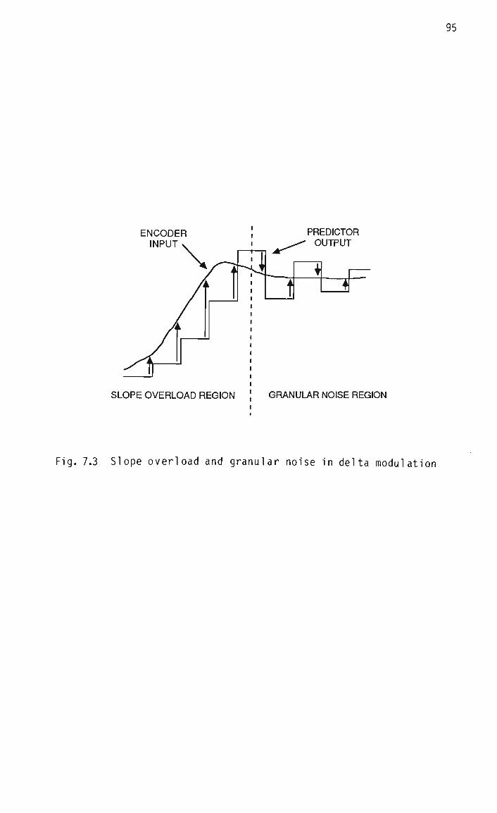
95
ENCODER INPUT
PREDICTOR OUTPUT
SLOPE OVERLOAD REGION GRANULAR NOISE REGION
Fig. 7.3 Slope overload and granular noise in delta modulation

96
noise is produced.
The quantizer input signal in this case is equal to the difference
between the encoder input and the predictor output, as indicated by the
vertical arrows in Fig. 7.3. Clearly, this difference signal has a
mean which is approximately zero in the granular noise region, but
which is non-zero in the slope overload region. This suggests that
adaptation of the quantizer to the shift in the mean might result in a
worthwhile performance improvement. The potential advantage of adapta
tion over companding is less clear for higher-resolution adaptive
quantizers, but it is shown in Section 7.6.4.2 that an improvement is
obtained at least in the case of 2-bit quantization.
7.4.3 Backward vs. forward adaptation
A distinction can be made between "forward" adaptive quantizers, which
are adapted from observations of the quantizer input signal, and "back
ward" adaptive quantizers, which are adapted from observations of the
quantizer output signal only [Jayant 84]. As the quantizer input
signal is not available to the decoder, forward adaptive quantizers
typically calculate adaptation parameters for a block of speech and
transmit these to the decoder as side information. This association
between forward adaptation and block coding makes it undesirable in
this application (as mentioned in Section 7.3.4), so that attention is
restricted here to backward adaptation, which can be implemented in a
sequential manner.
7.4.4 Syllabic, instantaneous, and hybrid adaptation
Adaptive quantizers can be further classified according to the "speed"
of their adaptation characteristics, which may be instantaneous (ie. an

97
attempt is made to track sample-to-sample variations in the signal
magnitude), syllabic (ie. an attempt is made to track changes in the
signal magnitude associated with different syllables), or some combina
tion of the two [Jayant 84]. Instantaneously adaptive quantizers are
able to quantize signal transients well, but can cause codec instabili
ty if their response is too rapid. This tendency is accentuated by low
quantizer resolution and the use of fixed predictors of order 2 or more
[Gibson 78]. At the other extreme, syllabically adaptive quantizers
are inherently stable in predictive coders, but quantize transients
poorly.
While it may appear that there should be an adaptation scheme which has
a response time somewhere between those of instantaneously and sylla
bically adaptive quantizers, and which could therefore be called
"critically damped", the fast attack/slow decay characteristic of
speech signals makes such a simple solution sub-optimal. A better
approach is represented by "pseudosyl labical ly" adaptive quantizers
[Nasr 84], which employ instantaneous adaptation during periods of
quantizer overload, and syllabic adaptation elsewhere. An adaptive
quantizer of this type is used in Continuously Variable Slope Delta
Modulation (CVSD) [Jayant 84].
An alternative to pseudosyl labic adaptation is hybrid adaptation, which
makes continuous use of both instantaneous and syllabic adaptation.
This technique was first used in a delta modulator [Magi 11 77], [Un
81], where it was shown to provide significant improvements in SNR and
dynamic range over other schemes [Un Jan. 80], and was later general
ized to include multi-bit quantizers [Nasr 84].
98
7.4.5 The optimization of backward adaptive quantizers
For a fixed quantizer, the decision and reconstruction levels used to
quantize a particular input sample depend solely on its magnitude (and
sign). Optimization of the quantizer therefore simply requires that
the decision and reconstruction levels are matched to the likely values
of the input samples.
However, in the case of a backward adaptive quantizer, the levels used
to quantize a particular sample are determined not only by its magni
tude, but also by one or more quantizer output bits. In principle,
these output bits could be related to the "past" or the "future", but
the use of future output bits (involving Delayed Decision or Multipath
Search Coding [Jayant 84]) requires considerably more processing than
the use of past output bits, so that attention is restricted here to
the latter case.
Optimization of a backward adaptive quantizer thus requires that the
decision and reconstruction levels are matched to the likely values of
the input samples for each possible combination of previous quantizer
output bits, which significantly increases the dimensionality of the
optimization problem. This tends to make optimization by means of
trial-and-error or using a random search procedure very time-consuming,
particularly since a large number of samples must be included in the
training sequence (>10 000) in order to obtain a statistically repre
sentative input.
An alternative to the above approach has been proposed for optimizing a
particular instantaneously adaptive quantizer [Castellino 77]. In this
procedure, the appropriate quantizer levels are updated after each
sample is coded, so that suitable values are "learnt" over the course

99
of the training sequence. While this procedure is much more efficient
than random search methods, it is not rigorous when the training se
quence is taken from a non-stationary signal, since it assigns more
weight to samples at the beginning of the sequence than at the end.
By contrast, the optimization procedure developed by Bello et al. for
the Statistical Delta Modulation (SDM) system assigns equal weight to
all samples in the training sequence [Bello 67]. The SDM system, which
is shown in Fig. 7.4, differs from conventional delta modulators in
that it does not use an integrator (ie. a linear predictor) in the
encoder feedback loop. Instead, a generalized mapping operation is
used to map past quantizer output bits, stored in a shift register, to
a predicted signal value, which is then used as a decision level for
calculating the output bit. A corresponding operation in the decoder
maps received bits to an estimated signal value, or reconstruction
level. The SDM optimization procedure iteratively improves these map
pings when the input to the system is a training sequence of samples.
The SDM system can thus be thought of as a form of backward adaptive
quantizer, as its decision and reconstruction levels at any given
sampling instant are dependent on a number of quantizer output bits.
Unfortunately, however, due to the relatively short memories which must
be used in practical implementations, account cannot be taken of long-
term (ie. syllabic) changes in the signal variance. As such changes
are considerable in speech, typically spanning 40 dB [Jayant 84], the
original SDM system is unsuitable for use in speech coding applica
tions.
Nevertheless, it has been found that an optimized SDM system performs
significantly better than a conventional DM system when coding a
stationary signal, to the extent that the coding rate can be reduced by

x (n) >_4<+>-v {n)
u(n)
Q b(n)
100
{p(j)J * j(n)
MEMORY t
CHANNEL
* MEMORY Mn)
* {q(k)} ->d(n)
Fig. 7.4 The Statistical Delta Modulation system

101
a factor of 1.5 for the same SNR [Bello 67]. This suggests that the
ability of the SDM coder to adapt to short-term changes in the varian
ce, mean and PDF shape of its input signal is important.
7.4.6 The Generalized Hybrid Adaptive Quantizer
7.4.6.1 Introduction
The fundamental problem with the SDM system, which prevents it from
being used in speech coding applications, is that it is unable to adapt
to long-term changes in the variance of its input signal. This problem
is overcome here by the addition of a syllabic compandor, thereby
creating a hybrid adaptive quantizer. (While this does not allow
adaptation to long-term changes in the mean and PDF shape of the quant
izer input signal, these are expected to be of secondary importance in
speech coding applications.) Furthermore, the scheme is generalized to
include multi-bit quantization. The resulting adaptive quantizer has
an arbitrary memory and code word length (in contrast to many previous
ly proposed schemes), and is therefore called the Generalized Hybrid
Adaptive Quantizer (GHAQ).
Fig. 7.5 shows the GHAQ in the context of a predictive encoder, the
GHAQ being the portion of the figure to the right of the vertical
dashed line. Its input is the prediction residual v(n), and its out
puts are the code word w(n) and the estimate s(n), which is a quantized
version of the prediction residual v(n). The GHAQ itself can be fur
ther divided into an instantaneously adaptive quantizer, which is shown
inside the dashed box in Fig. 7.5., and a syllabic compandor.
7.4.6.2 The syllabic compandor
The syllabic compandor makes use of an exponentially-weighted average
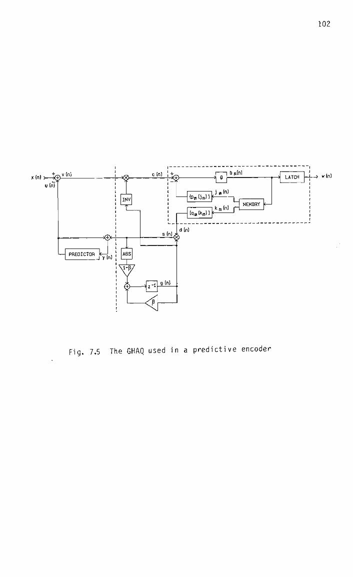
102
u(n)
• w(n)
Fig. 7.5 The GHAQ used in a predictive encoder
103
magnitude estimate. This is not the only possible weighting function
for average magnitude estimation, nor is it necessarily optimal
[Fischer 85], but the fact tht it can be realized in recursive form
makes its implementation considerably simpler than for most other
estimators. The average magnitude estimate g(n) is used to compress
the prediction residual v(n) before it is quantized, and to expand it
again afterwards. The compression operation is performed by inverting
g(n) before multiplying, as shown by the block labelled "INV" in Fig.
7.5. The block labelled "ABS" calculates the magnitude of the syllabic
compandor input sample. The minimum value of g(n) is constrained to be
unity, in order to prevent g(n) from diminishing indefinitely if the
input to the syllabic compandor is zero.
Multiplication of the quantizer decision and reconstruction levels by
g(n) would be equivalent to the compression/expansion representation
in Fig. 7.5, and would have the practical advantage that the inversion
operation could be avoided. However, the form shown in Fig. 7.5 is
used here, because it facilitates the description of the optimization
problem, although the hardware implementation of the codec described in
Chapter 8 uses the alternative form.
7.4.6.3 The instantaneously adaptive quantizer
The instantaneously adaptive quantizer in the GHAQ consists of a number
of sets of decision and reconstruction levels, a fixed 1-bit quantizer,
and a FIFO memory of length L bits, which stores one or more quantizer
output words. Multi-bit quantization is implemented by determining the
bits bm(n) ; ra = 0,1,...,M-1 in code word w(n) sequentially, starting
with the Most Significant Bit (MSBit) bM_ 1(n), and finishing with the
Least Significant Bit (LSBit) bQ(n), where M is the number of bits/

sample. This approach is similar to the "successive approximation"
technique used in analog-to-digital converters, although it is impor
tant to note that in the GHAQ the instantaneously adaptive quantizer is
adapted during the generation of each code word.
Associated with each value of the bit index m is a set of decision
levels Pffl = {pm(jm) i j m = 0,1,... ,Jm-l}, and a set of corresponding
reconstruction levels Qm = {qm(km)|km = 0,1,... ,1^-1}. The quantizer
level indices jm(n) and km(n) are generated by interpreting the con
tents of the memory as respective unsigned binary numbers. The exact
interpretation in each case depends on the current state of the
"successive approximation" process. This is illustrated in Fig. 7.6
using the 2-bit GHAQ with memory length L = 4 as an example, and the
sequential generation of these indices is described below.
First, ji(n) is generated, and this selects the appropriate decision
level from the set P^, enabling bj(n) to be determined. This bit is
latched to form the MSBit of w(n), and is also clocked into the memory,
in the position shown in Fig. 7.6. Next, j0(n) is generated, and this
selects a decision level from the set PQ, enabling bQ(n) to be deter
mined. This bit is latched to form the LSBit of w(n), and is also
clocked into the memory. Finally kQ(n) is determined, which selects a
reconstruction level from the set Qg, and this level becomes the quan
tizer output level d(n). The contents of the entire memory are then
shifted to the right by 2 bits, in preparation for the next input
sample c(n+l).
It can be seen that at no stage in the above process is the index kj(n)
required, implying that the set Q1 is not used. This observation can
be generalized to the sets Q M_ 1»QM-2 »- - -»Ql in an imPl e r a e n t a t i o n o f tne
M-bit GHAQ. However, these sets are required in the process of opti-

105
MEMORY
b0(n) bi(n) b0(n-l) bi(n-l)
j^n)
k^n)
j0(n)
kQ(n)
Fig. 7.6 Generation of the GHAQ level indices jm(n) and km(n) for code
word length M = 2 and memory length L = 4
106
mizing the GHAQ, since the optimum decision levels are defined in terms
of the optimum reconstruction levels, as is shown in Section 7.4.7.
The number of elements in each set Pm or Qm is determined by the number
of different values that j m or km can assume, which is in turn deter
mined by the memory length L and the bit index m, as illustrated in
Fig. 7.6. Since there are by definition two reconstruction levels
associated with each decision level, the number of levels in each case
can be expressed:
Jm = 2L"l-m (7.1)
m̂ = 2 L" m = 2Jm (7.2)
In the case of speech inputs, it is to be expected that the signal
statistics will be symmetrical with respect to the signal mean [Jayant
84], implying a corresponding symmetry in the quantizer decision and
reconstruction levels:
Pm(j'm) = -Pm^m-i-J'm) (7.3)
*M - "Wi-V (7-4)
Use of this assumption in an implementation of the GHAQ halves the
number of levels which must be stored, as the missing levels can be
derived from the stored ones by using the MSBit of the current code
word, bM_j(n), as a sign bit. In the interests of simplicity of pre
sentation, statistical symmetry of the signal is not assumed in the
derivation of the optimization procedure in Section 7.4.7. However, it
is assumed when the optimization procedure is actually used, by simply
averaging the corresponding values at each iteration.
Another implementation issue worth noting is that it was found empiric
ally that the SNR of the 2-bit GHAQ with speech inputs was degraded

107
only slightly (< 0.5 dB) by setting all the decision levels in the set
PQ to zero. This simplifies the implementation significantly, and
accordingly all references in the rest of this thesis to the 2-bit GHAQ
assume the use of this scheme.
7.4.7 Derivation of the GHAQ optimization procedure
There are three independent factors which simultaneously determine the
performance of the GHAQ with a given input signal, namely the syllabic
compandor coefficient 8, the memory length L, and the values of the
quantizer decision and reconstruction levels. An iterative procedure
is derived below which is suitable for finding optimum quantizer levels
for given 8 and L. This procedure is similar to the Lloyd-Max proce
dure for optimizing fixed quantizers [Lloyd 57], [Max 60], and the
optimization procedure associated with the SDM system [Bello 67].
It is assumed for the purposes of quantizer optimization that speech is
"quasi-ergodic", in the sense that if time averages are calculated for
a sufficiently long period, they will tend to approach ensemble aver
ages across a correspondingly large number of utterances [Linde 80].
Furthermore, a training sequence representative of general speech sig
nals is used, as is described in Section 7.4.9. For these reasons,
time-independent random variables x,y, etc., rather than individual
samples x(n), y(n), etc. are considered in the analysis below.
A quadratic cost function is assumed, as done in [Max 60] and [Lloyd
57], although other functions could also be used, as is discussed in
Section 7.4.8. The distortion to be minimized is thus:
D = E{(x - y)2} (7-5)
where E{#} denotes expectation. It can be seen from Fig. 7.5 that:

108
X = V + u
y = s + u
Also:
v = c g
s = d g
Thus (7.5) can be rewritten:
D = E{g2(c - d)2} (7.6)
As d is the random variable associated with the quantizer output level
d(n), it can only take on values equal to the reconstruction levels in
the sets Qm ; m = 0,1,...,M-l. In the interests of clarity of presen
tation, the subscript m is omitted in the development below, with the
understanding that the analysis is valid for any bit bm(n) in code word
w(n). Associated with each decision level p(j) are two reconstruction
levels, q(kjb=0) and q(k|b=l), so that (7.6) can be expressed:
j_l «o p(j)
D = J [ / J g2(c - q(k|b=0))2 fcg(c,g|j) dc dg fj(j) j=0 -0O--0
+ iT 92(c - q(k|b=l))2 fcg(c,g|j) dc dg fj(j) ] (7.7) -«*p(j)
where : fc (c,g|j) is the joint PDF of c and g conditional upon j
fj(j) is the PDF of j
A crucial issue in the development of an optimization procedure from
(7.7) is the extent to which the PDFs fcg(c,g|j) and fj(j) are indepen
dent of the decision levels p(j) for j = 0,1,...,J-1, as (7.7) must be
differentiated with respect to these levels. Strictly, g(n) is a
weighted sum of quantizer output samples d(n),d(n-l),...,d(l), which
109
are in turn dependent on the reconstruction levels, and hence on the
decision levels. However, in order to maintain a tractable analysis,
it is assumed in the development below that the assumption of indepen
dence is valid. This point is discussed further in Section 7.4.10,
where the performance of the optimization procedure is evaluated.
In order to minimize D, it is differentiated with respect to the p(j)'s
and q(k)'s, and the derivatives are equated with zero. This gives
necessary, although not sufficient, conditions for a local minimum.
Details of the minimization are given in Appendix A, and the main
results are:
P(j) = 1/2 [ q(j) + q(J+K/2) ] ; j = 0,1,...,J-1 (7.8)
E{cg2|k} q(k) = ; k = 0,1,...,K-1 (7.9)
E{g2|k}
Equation (7.8), which is identical to the design equation obtained for
non-uniform fixed quantizers [Max 60], [Lloyd 57], states that the
optimum decision levels lie midway between the corresponding recon
struction levels. Equation (7.9) states that the optimum reconstruc
tion levels are the "weighted" centroids of the quantizer input signal
on the corresponding quantizer intervals.
In order to optimize the GHAQ, initial sets {p(j)| and {q(k)} are
assumed, and these are then iteratively improved with a training se
quence of input samples by repeated evaluation of (7.8) and (7.9),
where the expectations are replaced by sample averages. This procedure
is repeated for values of 8 in the range [0,1), in order to optimize
this parameter simultaneously with the quantizer levels. The memory
length L is assumed to be given, but unlike 8, there is no theoretical
no
upper bound on this parameter. Rather, it is expected that increasing
L will result in a monotonic increase in the SNR of the GHAQ, and that
the SNR wil 1 tend to saturate above a certain value of L, due to the
finite correlation time of the input signal, as found for the SDM
system [Bello 67]. In practice, L will be constrained by the desire
for a simple implementation.
If it is assumed that c and g are independent random variables, then
(7.9) reduces to:
q(k) = E{c|k} ; k = 0,1,...,K-l (7.10)
which corresponds to the well-known result for fixed quantizers [Max
60], [Lloyd 57]. However, it was found empirically that if (7.10) is
used instead of (7.9) in the optimization procedure, unsatisfactory
convergence behaviour results in many instances, indicating that the
assumption of independence of c and g is not valid in general.
7.4.8 Performance measures
The distortion measure used in the GHAQ optimization procedure is the
Mean Square Error (MSE), implying that the procedure will attempt to
maximize the SNR of the GHAQ. The MSE has the advantage that it is
easily calculated and tractable, and is widely used in the optimization
and evaluation of speech coding systems [Jayant 84]. However, as the
ultimate objective is to maximize the perceived quality of the decoded
speech, the question arises as to how well SNR is correlated with
perceptual judgements.
A number of studies have addressed this issue [McDermott 78], [Nakatsui
82], [Scagliola 79], [Barnwell 82], and average correlations between
SNR and subjective judgements in the range 0.24 to 0.89 have been

Ill
reported. However, the major conclusion of these studies is that SNR
is not a good predictor of subjective quality ratings for different
coder types (such as when both waveform coders and vocoders are in
cluded in the tests). When only time-domain waveform coders are in
cluded, the correlation between SNR and subjective judgements improves
considerably [Nakatsui 82].
It has also been found in these studies that segmental SNR (SNRSEG)
[Jayant 84] is a better predictor than SNR of the subjective quality of
waveform coded speech, and has correlations in the range 0.77 to 0.95.
The distortion measure associated with SNRSEG is the Energy-Weighted
Mean Square Error (EWMSE) [Chen 87], and while this measure involves
more computation than the MSE, it is considerably simpler than alterna
tive distortion measures such as the LPC Cepstrum Distance [Kitawaki
82]. Although the EWMSE has not been used in the GHAQ optimization
procedure described here, it should be directly applicable, and this
represents a reasonable area for further work. Nevertheless, SNRSEG
figures are given in all performance evaluations of the GHAQ, in order
to allow comparison with SNR figures.
7.4.9 The training set
When any algorithm is optimized by tailoring its characteristics using
a particular training set, it is important to ensure that the training
set is representative of the class of signals from which it is taken
[Linde 80]. In the case of speech, significant variations in training
set statistics can be caused by variations in the linguistic material
used, and in the identity (in particular the sex), of the speaker. For
these reasons, a special training set containing "phonetically bal
anced" linguistic material spoken by both male and female speakers, was
constructed, as is standard practice in evaluations of speech coders

112
[IEEE 69]. This training set, consisting of Sentences 1 to 4 in Appen
dix E, was used in all GHAQ optimization runs.
It was observed during the development of the GHAQ that there was in
general little difference among the sets of optimum quantizer levels
obtained for training sets containing different (but phonetically
balanced) utterances by different speakers. By contrast, significant
differences were noted between the sets of optimum quantizer levels
when the training set contained only voiced speech or only unvoiced
speech, thus emphasizing the need to use phonetically balanced
utterances.
As a check on the representative nature of the training set, the per
formance of the optimized 2-bit GHAQ for this set was compared with its
performance for another input sequence (Sentences 5 to 8 in Appendix
E). The difference between the performance figures obtained in each
case was 0.26 dB for SNR and 0.02 dB for SNRSEG, and in fact the
outside-training-set utterance yielded the higher figures. It is
therefore concluded that the above training set is sufficiently repre
sentative of general speech signals for this application.
7.4.10 Evaluation of the GHAQ optimization procedure
7.4.10.1 Introduction
There are a number of issues which must be addressed in order to
determine the usefulness of the optimization procedure derived in
Section 7.4.7. Firstly, it needs to be established whether and under
what conditions the procedure converges in practice. Due to the ass
umption that the probability distributions of c and g are independent
of the quantizer levels, convergence cannot be guaranteed from the
113
analysis. Secondly, if the procedure converges, does the point of
convergence represent an optimum design, ie. has the objective function
been minimized? Thirdly, if the point of convergence is a minimum of
the objective function, is the minimum global or not? Fourthly, what
are the effects of the GHAQ parameters 8 and L on the peak performance
obtained?
7.4.10.2 Convergence
The optimization procedure was evaluated with 1-bit and 2-bit versions
of the GHAQ, operating at respective sampling rates of 16 kHz and 8
kHz, and with speech inputs. The procedure was found to converge from
a number of different starting points and for a range of values of 8
and L, although some exceptions are described below.
Typical convergence characteristics are shown in Figs. 7.7 and 7.8,
where SNR is plotted against the iteration number i. (The SNRF measure
used in Fig. 7.7 is the SNR calculated after the decoder output fil
ter.) While convergence is not necessarily monotonic, as can be seen
from Fig. 7.7, the final optima are stable with respect to further
iteration in both cases. Also plotted in these figures is a converg
ence measure 6^, which is defined:
K-l 6, = 1/(K-D [ I (q(k)|.- q(k)l. ) 2 ] ^ 2 (7.11)
k=0 1 1-1
where the vertical bars indicate the iteration at which q(k) is eval
uated. This convergence measure is used to provide a termination
criterion for the optimization procedure, namely 6-,- < 0.05.
The GHAQ reconstruction levels corresponding to the first and fifteenth
iterations in Figs. 7.7 and 7.8 are given in Tables 7.1 and 7.2,

114
X X * X~
X SNRF
1.50
1.25
1.00
0.75^-
0.50
0.25
JI IB 2 3 4 5 G 7 B 9 10 11 12 13 14 15 0.00
Fig. 7.7 Convergence characteristics of the optimization procedure for
the 1-bit GHAQ
X X X X X X X—-x X X- X } 1.50
X SNR
M= JH m a K j m at-
1.25
1.00
0.75co
- 0.50
0.25
10 11 12 13 14 15 0.00
Fig. 7.8 Convergence characteristics of the optimization procedure for
the 2-bit GHAQ

b0(n)
0
0
0
0
0
0
0
0
b0(n-l)
0
0
0
0
1
1
1
1
0
0
0
0
1
1
1
1
b0(n-2)
0
0
1
1
0
0
1
1
0
0
1
1
0
0
1
1
b0(n-3)
0
1
0
1
0
1
0
1
0
1
0
1
0
1
0
1
k(n)
0
1
2
3
4
5
e 7
8
9
10
11
12
13
14
15
q(k)
i=0
1.50
1.50
1.50
1.50
-0.50
-0.50
-0.50
-0.50
0.50
0.50
0.50
0.50
-1.50
-1.50
-1.50
-1.50
1=15
3.21
2.73
1.63
1.61
1.02
0.58
0.07
0.16
-0.16
-0.07
-0.58
-1.02
-1.61
-1.63
-2.73
-3.21
Table 7.1 Reconstruction levels q(k) of the 1-bit GHAQ before
iteration i = 1 and after iteration i = 15 of the
optimization procedure
b0(n)
0
0
0
0
0
0
0
0
1
1
1
1
1
1
1
1
bi<n)
0
0
0
0
1
1
1
1
0
0
0
0
1
1
1
1
bo(n-D
0
0
1
1
0
0
1
1
0
0
1
1
0
0
1
1
bi(n-l)
0
1
0
X
0
1
0
1
0
1
0
1
0
1
0
1
k(n)
0
1
2
3
4
5
6
7
e 9
10
11
12
13
14
15
q(k)
i=0
1.50
1.50
1.50
1.50
-0.50
-0.50
-0.50
-0.50
0.50
0.50
0.50
0.50
-1.50
-1.50
-1.50
-1.50
i=15
3.34
1.67
1.86
2.00
-0.55
-0.57
-0.46
-0.91
0.91
0.46
0.57
0.55
-2.00
-1.86
-1.67
-3.34
Table 7.2 Reconstruction levels q(k) of the 2-bit GHAQ before
iteration i = 1 and after iteration i = 15 of the
optimization procedure
116
respectively. The corresponding decision levels can be calculated
straightforwardly using equation (7.8). Although all 16 reconstruction
levels are given in each case for the sake of clarity, the fact that
they are constrained to be symmetrical means that only 8 need be stored
in a practical implementation, as explained in Section 7.4.6.3.
The choice of a starting point for the GHAQ optimization procedure is
an important issue, not only because it affects the number of itera
tions required for convergence, but also because in extreme cases the
adaptive quantizer design associated with a particular point will be
unstable (such as when all the reconstruction levels are greater than
unity), with the result that the procedure will not converge. The
starting set shown in Table 7.1 is chosen from intuitive considera
tions, by distinguishing those cases in which an increase in signal
variance is indicated from those in which a decrease is indicated.
However, as the memory length increases, this intuitive approach becomes
less useful, and a more rigorous way of finding a starting set is
required.
This issue has been addressed in a study of adaptive vector quantizers,
and a two-phase optimization procedure has been proposed [Chen 87]. In
Phase 1, the quantizer is optimized using unquantized inputs to the
"gain predictor" (equivalent to the syllabic compandor in the GHAQ).
The use of unquantized values ensures that the adaptive quantizer
cannot become unstable during the optimization process, no matter what
starting set is used. Once Phase 1 has converged, its final design is
used as a starting point for Phase 2, in which quantized syllabic
compandor inputs are used. This second phase thus corresponds to the
optimization procedure derived in this thesis, and Phase 1 is a means
of finding a good starting set for the procedure.

117
Non-convergence of the optimization procedure was observed when an
attempt was made to optimize the l-blt GHAQ in a delta modulator with a
value of p which was too small and/or a predictor coefficient hl which
was too small. This phenomenon may be related to the assumption that
the conditional PDFs in equation (7.7) are independent of the quantizer
levels, which becomes less valid as the quantization noise increases
(eg. when the quantizer resolution is reduced).
Furthermore, there are two feedback loops around the instantaneously
adaptive quantizer in Fig. 7.5, which tend to compensate for the
effects of quantization noise. These loops contain the predictor and
the syllabic compandor, respectively. Reducing the value of the pred
ictor coefficient reduces the amount of negative feedback applied by
the first loop, and reducing the syllabic compandor coefficient reduces
the "smoothing" action of the second. The effect in both cases is to
perturb the PDFs between iterations of the optimization procedure,
thereby hindering convergence. However, it was found that with speech
inputs convergence always occurred for 8 > 0.4 and hx > 0.5, and these
limits are sufficiently distant from the respective optimum values
(given in Sections 7.4.10.4 and 7.6.3.1), to be unrestrictive in prac
tice.
7.4.10.3 Design optimality
The optimal ity of the final design was verified in the cases of Figs.
7.7 and 7.8 by means of a general-purpose search procedure [Nelder 65],
which failed to improve by more than 0.2 dB on the final SNRs shown in
these figures. However, due to the large number of iterations required
by the general-purpose procedure, this verification process was not
extended to other cases.
118
The question of whether a local minimum is also global is common to all
optimization procedures, and cannot be answered conclusively without
knowledge of the nature of the objective function, which is not avail
able in this case. However, it is worth noting that an empirical
technique has been suggested for ensuring the location of a global
optimum using the Lloyd-Max optimization procedure [Linde 80]. It
involves the addition of independent noise to the input signal, the
noise variance being gradually attennuated as the procedure progresses.
While this technique has not been evaluated with the GHAQ optimization
procedure, it is likely to be applicable, and represents a possible
area for further work.
7.4.10.4 The effect of 0 on the performance of the GHAQ
The effect of varying 8 on the performance of the 1-bit and 2-bit GHAQs
can be seen in Figs. 7.9 and 7.10, respectively. The GHAQ was re-
optimized for each value of 8 plotted. A first-order predictor was
used, and L was fixed at 4, as negligible interaction was observed
between the respective effects of 8 and L on performance. It can be
seen that there is a well-defined performance peak in each case, occur
ring at approximately 8 = 0.97 for the 1-bit GHAQ, and 8 = 0.94 for the
2-bit GHAQ. The difference between the SNR and SNRSEG curves (up to
1.2 dB) is due to the MSE distortion measure used by the optimization
procedure, which gives more significance to large-amplitude than small -
amplitude signals.
The optimum values of 8 in Figs. 7.9 and 7.10 correspond to a syllabic
compandor time constant of about 2 mS in both cases, which is somewhat
lower than corresponding values used in other hybrid adaptive quanti
zers (5 - 20mS) [Nasr 84], [Un 81]. This may be attributed to the fact

15.5
DQ "D 14.5
L_ (J Ld IS) CK 13.5 Z 01 73 C to 12.5 LL
CK Z
cn
X SNRF 0 SNRSEGF
1 1 . 5 I I i i i I i r i i I i i i i I i i i i I i i .. I .... I .... I .... I .... | .... I 0 . 1 . 2 . 3 . 4 . 5 . G . 7 . 8 . 9 1
fi
Fig. 7.9 Performance of the optimized 1-bit GHAQ vs. p
15.5
m 14.5
u Ld LG CK 13.5 01
T3 C
Z 01
12.5
11.5 .... 1 • • * ' • • • i . . . . i . . . . i _ i i i i i -
0 SNRSEG 0
i i i i i i i i i i i i i .I. I 0 .1 .2 .3 .4 .5
fi
.6 .7 .8 .3 1
Fig. 7.10 Performance of the optimized 2-bit GHAQ vs. 6

120
that the instantaneously adaptive quantizers in the latter schemes
typically have a more rapid response than does the corresponding quan
tizer in the GHAQ, implying that a more rapidly-responding syllabic
compandor is required in the GHAQ.
7.4.10.5 The effect of L on the performance of the GHAQ
In Figs. 7.11 and 7.12, the effect on performance of varying the memory
length L is shown for the 1-bit and 2-bit GHAQs. Only even values of L
are shown in Fig. 7.12, because it is required that an integral number
of 2-bit code words are stored in the quantizer memory. Values of L
greater than 8 were not considered, due to the relatively large amount
of storage that would be required for the quantizer levels. As in the
previous section, the GHAQ was re-optimized for each value of L, and a
first-order predictor was used. The optimum values of p found in the
previous section (0.97 and 0.94) were used for the 1-bit and 2-bit
GHAQs, respectively.
The increase in performance with increasing L is as predicted from the
discussion in Section 7.4.7, although negligible improvement is observ
able above L = 4. Again, the difference between the SNR and SNRSEG
figures can be attributed to the MSE distortion measure used in the
optimization procedure.
7.5 The predictor in the primary coder
7.5.1 Introduction
In order to enable a fair comparison to be made among various ADM and
ADPCM coders, it is necessary to ensure that the predictor used in each
case is optimized, as this can have a significant effect on coder
performance. Predictors used in speech coders are usually constrained

15.5
ra 13 14.5
CJ Ld V) LY. 13.5
CO
73 C rd
L_ CK Z
cn
12.5
11.5 5 L
X SNRF 0 SNRSEGF
Fig. 7.11 Performance of the optimized 1-bit GHAQ vs. L
L5.5
T5
c fd
CK
z cn
12.5
LI.5
X SNR 0 SNRSEG
5
L
Fig. 7.12 Performance of the optimized 2-bit GHAQ vs. L
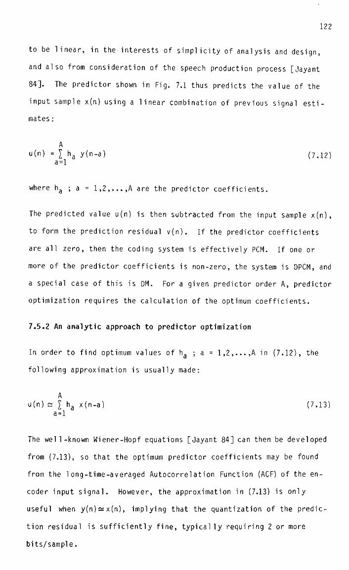
122
to be linear, in the interests of simplicity of analysis and design,
and also from consideration of the speech production process [Jayant
84]. The predictor shown in Fig. 7.1 thus predicts the value of the
input sample x(n) using a linear combination of previous signal esti
mates :
A "(n) = I ha y(n-a) (7.12)
a=l
where ha ; a = 1,2,...,A are the predictor coefficients.
The predicted value u(n) is then subtracted from the input sample x(n),
to form the prediction residual v(n). If the predictor coefficients
are all zero, then the coding system is effectively PCM. If one or
more of the predictor coefficients is non-zero, the system is DPCM, and
a special case of this is DM. For a given predictor order A, predictor
optimization requires the calculation of the optimum coefficients.
7.5.2 An analytic approach to predictor optimization
In order to find optimum values of ha ; a = 1,2,...,A in (7.12), the
following approximation is usually made:
A u(n) ~ I ha x(n-a) (7.13)
a=l
The well-known Wiener-Hopf equations [Jayant 84] can then be developed
from (7.13), so that the optimum predictor coefficients may be found
from the long-time-averaged Autocorrelation Function (ACF) of the en
coder input signal. However, the approximation in (7.13) is only
useful when y(n)^x(n), implying that the quantization of the predic
tion residual is sufficiently fine, typically requiring 2 or more
bits/sample.

This approximation can therefore not be used to find the optimum pre
dictor coefficients in delta modulators, except in the special case
where a first-order predictor is used and the first coefficient Pl of
the long-time-averaged ACF of the input signal is close to unity
[Jayant 78], implying that the magnitude of the prediction residual is
small in comparison with the signal magnitude.
The above ACF criterion is usually satisfied in speech coding applica
tions using high-quality microphones with uniform frequency response.
However, when a standard telephone microphone is used, the resulting
pre-emphasis of the input speech reduces P1 considerably. For example,
it was found in this project that the same utterance captured by a
high-quality microphone and a telephone microphone had p, = 0.95 and p}
= 0.66, respectively, at a sampling rate of 16 kHz.
Another factor to be considered is the interaction which can occur
between the backwardly adaptive quantizer and the predictor [Gibson
78], and which can perturb the optimum predictor coefficients from the
values which might otherwise be expected. For this reason, as well as
because of the coarseness of the quantization process, an alternative
method to (7.13) for finding the optimum predictor coefficients is
required in the case of ADM.
7.5.3 An iterative approach to predictor optimization
In this thesis, predictor optimization was performed for a number of
ADM coders using a mul tivariabl e search technique, known as the
"Simplex" Method [Nelder 65], or more accurately, the Flexible Poly
hedron Method (FPM) [Himmelblau 72]. (Details of the coders are given
in Section 7.6) Because the FPM does not use derivatives of the objec-

124
tive function, no analysis of the optimization problem is necessary.
The only restriction is that the objective function must be convex,
otherwise a non-global minimum might be found.
The distortion measure used in this case was the MSE, implying an SNR
performance measure, as for the GHAQ optimization procedure. Strictly,
the performance measure applied to oversampled systems should be SNRF
[Jayant 84] (ie. the SNR calculated after filtering at the decoder
output). However, in this work it is assumed that the shape of the
quantization noise spectrum is independent of the predictor coeffi
cients, implying that optimization of the SNR is equivalent to optimi
zation of the SNRF. This assumption considerably reduces the computing
time required to perform each optimization, by eliminating the need to
simulate the decoder output filter.
The Flexible Polyhedron Method was found to perform well in this appli
cation, although as it does not estimate derivatives it takes longer to
converge than steepest-descent algorithms. Convergence was observed to
be smooth and unambiguous, at least for the first- and second-order
predictors studied. The optimum predictor coefficients found in each
case are given in Section 7.6.3.1.
7.6 Comparative performance tests
7.6.1 Introduction
In order to evaluate the usefulness of the optimized GHAQ, the perform
ance figures of 1-bit and 2-bit versions were compared with those of a
representative selection of other adaptive quantizers of similar com
plexity. This selection included the Constant Factor Delta Modulation
Adaptive Quantizer (CFDMAQ) [Jayant 70], the Hybrid Companding Delta
Modulation Adaptive Quantizer (HCDMAQ) [Un 81], and a 2-bit version of

125
the "Adaptive Quantizer with a One-Word Memory", which is referred to
here as the Jayant Adaptive Quantizer (JAQ) [Jayant 73]. Details of
these algorithms are given in Appendix F.
While the Continuously Variable Slope Delta Modulation Adaptive Quant
izer (CVSDAQ) [Jayant 84] is equally well known, it was not included in
the comparison, as it is known to have a limited dynamic range [Un Jan.
80]. By contrast, the dynamic range of the other algorithms can be
made arbitrarily large by setting the step size limits appropriately.
7.6.2 Test conditions
The test signal for the comparisons consisted of Sentences 1 to 4 in
Appendix E. While strictly speaking this signal is "inside" the train
ing set for the GHAQ, the GHAQ is not given an unfair advantage over
the other adaptive quantizers, because the utterance is designed to be
representative of general speech signals, as discussed in Section 7.4.9.
Both a telephone handset and a high-quality microphone were used for
speech acquisition, in order to allow the effect of each transducer on
the coding algorithms to be assessed. The performance measures used
were SNR and SNRSEG, although for the oversampled DM systems the
corresponding measures SNRF and SNRSEGF [Jayant 84] were also calcu
lated, as explained in Section 7.5.3. The decoder output filter in
this case had a 6th-order Chebyshev low-pass characteristic, with 0.5
dB passband ripple and a cutoff frequency of 3.4 kHz.
Fixed predictors of order 0, 1, and 2 were used, with the exception
that the zero-order predictor was not used with the DM systems, as this
resulted in coder instability. The optimum predictor coefficients were
found for the DM systems using the Flexible Polyhedron Method, and for
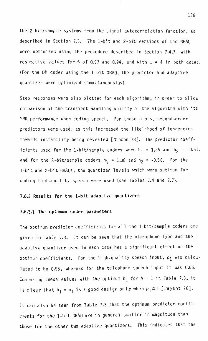
126
the 2-bit/sample systems from the signal autocorrelation function, as
described in Section 7.5. The 1-bit and 2-bit versions of the GHAQ
were optimized using the procedure described in Section 7.4.7, with
respective values for 8 of 0.97 and 0.94, and with L = 4 in both cases.
(For the DM coder using the 1-bit GHAQ, the predictor and adaptive
quantizer were optimized simultaneously.)
Step responses were also plotted for each algorithm, in order to allow
comparison of the transient-handling ability of the algorithm with its
SNR performance when coding speech. For these plots, second-order
predictors were used, as this increased the likelihood of tendencies
towards instability being revealed [Gibson 78]. The predictor coeff
icients used for the 1-bit/sample coders were h^ = 1.25 and l^ = -0.31,
and for the 2-bit/sample coders hj = 1.38 and h2 = -0.50. For the
1-bit and 2-bit GHAQs, the quantizer levels which were optimum for
coding high-quality speech were used (see Tables 7.4 and 7.7).
7.6.3 Results for the 1-bit adaptive quantizers
7.6.3.1 The optimum coder parameters
The optimum predictor coefficients for all the 1-bit/sample coders are
given in Table 7.3. It can be seen that the microphone type and the
adaptive quantizer used in each case has a significant effect on the
optimum coefficients. For the high-quality speech input, pj was calcu
lated to be 0.95, whereas for the telephone speech input it was 0.66.
Comparing these values with the optimum h1 for A = 1 in Table 7.3, it
is clear that hx = p1 is a good design only when p^l [Jayant 78].
It can also be seen from Table 7.3 that the optimum predictor coeffi
cients for the 1-bit GHAQ are in general smaller in magnitude than
those for the other two adaptive quantizers. This indicates that the

127
CFOMAQ
HCDMAQ
GHAQ
HIGH-QUALITY SPEECH
A=l
hl
0.95
0.95
0.93
A=2
hl
1.25
1.34
0.96
h2
-0.31
-0.39
-0.03
TELEPHONE SPEECH
A=l
hl
0.75
0.80
0.55
A=2
hl
0.95
0.96
0.69
h2
-0.39
-0.33
-0.35
Table 7.3 Optimum predictor coefficients ha for the 1-bit/sample
coders with predictor order A = 1 and 2
b0(rO
0
0
0
0
0
0
0
0
b0(n-l)
0
0
0
0
1
1
1
1
0
0
0
0
1
1
1
1
b0(n-2,
0
0
1
1
0
0
1
1
0
0
1
1
0
0
1
1
b0(n-3)
0
1
0
1
0
1
0
1
0
1
0
1
0
1
0
1
k(n)
0
1
2
3
4
5
6
7
8
9
10
11
12
13
14
15
q(k)
HIGH-QUALITY
SPEECH
A=l
3.13
2.64
1.58
1.51
1.07
0.55
0.02
0.07
-3.13
-2.64
-1.58
-1.51
-1.07
-0.55
-0.02
-0.07
A=2
3.16
2.67
1.59
1.53
1.07
0.60
0.11
0.19
-3.16
-2.67
-1.59
-1.53
-1.07
-0.60
-0.11
-0.19
TELEPHONE
SPEECH
A=l
2.22
1.66
0.85
2.31
-0.28
0.84
0.34
1.04
-2.22
-1.66
-0.85
-2.31
0.28
-0.84
-0.34
-1.04
A=2
2.48
1.76
0.96
2.05
0.47
0.86
0.42
0.65
-2.48
-1.76
-0.96
-2.05
-0.47
-0.86
-0.42
-0.65
Table 7.4 Optimum reconstruction levels q(k) for the 1-bit GHAQ with
L = 4 for predictor order A = 1 and 2

GHAQ is taking over part of the function of the predictor, by removing
some of the correlation from the input signal. The reason the GHAQ is
able to do this, whereas the other adaptive quantizers are not, is that
it produces an "optimal" prediction of its input signal on the basis of
past observations, ie. it generates a "Bayesian" estimate [Schwartz
75].
The optimum reconstruction levels for the 1-bit GHAQ are given in Table
7.4, and the effect of the microphone type and of the predictor order
on these levels can clearly be seen. This observation supports the
hypothesis put forward in Section 7.4.1 that 1-bit adaptive quantizers
optimized with high-quality speech are not well matched to telephone
speech.
7.6.3.2 SNR results
Tables 7.5 and 7.6 show that in all cases the 1-bit GHAQ gives an
improvement over the other adaptive quantizers, in terms of SNR(F) and
SNRSEG(F). The performance advantage is most marked for the telephone
speech input, which can be attributed to the fact that the other adap
tive quantizers were designed for signals with a higher degree of
adjacent-sample correlation. (Due to the complex interaction between
the predictor and the adaptive quantizer in a DM system, the pre-
emphasis introduced by the telephone microphone cannot be completely
compensated for by manipulation of the predictor coefficients alone.)
Furthermore, the performance of the 1-bit GHAQ is seen to be virtually
independent of the predictor order in all cases, which can be attrib
uted to the ability of the GHAQ to perform a degree of prediction, as
mentioned in Section 7.6.3.1.
It is to be expected that if the quantization noise in the DM systems

129
CFDMAQ
HCDMAQ
GHAQ
HIGH-QUALITY SPEECH
A=l
SNR
10.2
11.7
13.7
SNRSEG
9.0
10.2
12.0
A=2
SNR
11.4
13.0
13.8
SNRSEG
10.2
11.4
12.0
TELEPHONE SPEECH
A=l
SNR
0.7
2.5
5.7
SNRSEG
1.3
3.2
5.6
A=2
SNR
3.6
3.0
6.0
SNRSEG
3.9
4.2
5.7
Table 7.5 SNR and SNRSEG [dB] figures for the 1-bit/sample coders with
predictor order A = 1 and 2
CFDMAQ
HCOMAQ
GHAQ
HIGH-QUALITY SPEECH
A=l
SNRF
12.7
13.7
14.6
SNRSEGF
11.7
12.2
13.1
A=2
SNRF
12.9
13.5
14.7
SNRSEGF
11.9
12.1
13.1
TELEPHONE SPEECH
A=l
SNRF
3.8
3.3
7.0
SNRSEGF
4.7
4.8
7.2
A=2
SNRF
5.7
3.4
7.2
SNRSEGF
6.4
5.2
7.4
Table 7.6 SNRF and SNRSEGF [dB] figures for the 1-bit/sample coders
with predictor order A = 1 and 2

130
were uniformly spectrally distributed, then filtering the decoder out
put signal to 3.4 kHz would give increases in the SNRF and SNRSEGF
figures over the SNR and SNRSEG figures equal to about 3 dB, since the
quantization noise power should be approximately halved. However,
comparing the results in Table 7.5 with those in Table 7.6, it is
apparent that the increase is almost always less than 3 dB in practice,
and furthermore that it is dependent on the type of adaptive quantizer
used.
The increase tends to be greatest for the CFDMAQ, and smallest for the
GHAQ, which can be related to the fact that the CFDMAQ has a faster
transient response than the 1-bit GHAQ (see the step response plots),
implying that the CFDMAQ tends to generate a greater proportion of
high-frequency noise than the 1-bit GHAQ. This suggests that the SNRF
of the 1-bit GHAQ might be improved in oversampled systems by spectral
ly redistributing its quantization noise, so that more of the noise lay
outside the signal band. This would require the use of a frequency-
weighted distortion function in the optimization procedure, and repre
sents an area for further work. Alternatively, the reduced level of
out-of-band noise in DM systems using the 1-bit GHAQ would justify a
relaxation of the rol 1-off requirements of the decoder output filter.
7.6.3.3 Step responses
The step response plots are shown in Figs. 7.13 - 7.15. It can be seen
that the CFDMAQ responds more quickly to a step input than does the 1-
bit GHAQ optimized for speech. However, the penalty for the rapid
response of the CFDMAQ is relatively severe oscillatory behaviour after
the step level has been reached. The benefit to be gained by increas
ing the quantizer memory length can be seen from the response of the

200
160
150
140
120
100
8 0
50
40
20
0 80
i/VVVVWli i i 1l
p u P ijywvWw yWlrVV"
I 100 120 140 160 160
n
200 220 240 260 280
Fig. 7.13 Step response of the CFDMAQ
200
160
160
140
120
100
80
60
40
20
0 80
/
flWpll||ll|iliiPlwJ
100 120 140 1G0 180
n
200 220 240 260 280
Fig. 7.14 Step response of the HCDMAQ

132
200
280
Fig. 7.15 Step response of the 1-bit GHAQ

HCDMAQ, which has a memory one bit longer than that of the CFDMAQ.
(The HCDMAQ is essentially an instantaneously adaptive quantizer for
the short period of time defining the overload response).
As the memory in the 1-bit GHAQ can be made arbitrarily long, it is
reasonable to believe that an overload response similar to that of the
instantaneously adaptive quantizers could be obtained while avoiding
the subsequent oscillatory behaviour, if the quantizer were optimized
for a step input. This possibility is not of particular interest in
the context of speech coding, but would be in video coding applica
tions, where step-like transients are frequently encountered [Weiss
75].
7.6.4 Results for 2-bit adaptive quantizers
7.6.4.1 Optimum coder parameters
The optimum predictor coefficients for the high-quality speech input
were hj = 0.92 for a first-order predictor and hj = 1.38, h2 = -0.50
for a second-order predictor. With the telephone speech input, the
optimum coefficients for first- and second-order predictors were vir
tually zero, an observation which is also made in [Cattermole 69].
Accordingly, the predictor was omitted in this case.
The optimum reconstruction levels for the 2-bit GHAQ are shown in Table
7.7. The effect of the microphone type and predictor order on the
optimum levels is less pronounced in this case than for the 1-bit GHAQ,
which can be attributed to the reduced interaction between the adaptive
quantizer and the predictor. While the parameters of the 2-bit JAQ are
given in Appendix F, it should be noted that in the specific case of
the telephone speech input, the appropriate step size multipliers are
those specified for DPCM rather than PCM, due to the de-correlation of

b0(n)
0
0
0
0
0
0
0
0
"»x(n)
0
0
0
0
1
1
1
1
0
0
0
0
1
1
1
1
b0(n-l)
0
0
1
1
0
0
1
1
0
0
1
1
0
0
1
1
b^n-1)
0
1
0
1
0
1
0
I
0
1
0
1
0
1
0
1
k(n)
0
1
2
3
4
5
6
7
8
9
10
11
12
13
14
15
q{kl
HIGH-QUALITY
SPEECH
A=0
2.19
1.28
1.28
1.94
-0.44
-0.45
-0.25
-1.15
1.15
0.25
0.45
0.44
-1.94
-1.28
-1.28
-2.19
A=l
3.34
1.60
1.75
1.95
-0.54
-0.51
-0.42
-0.91
0.91
0.42
0.51
0.54
-1.95
-1.75
-1.60
-3.34
A=2
3.43
1.67
1.79
2.07
-0.66
-0.51
-0.47
-0.77
0.77
0.47
0.51
0.66
-2.07
-1.79
-1.67
-3.43
TELEPHONE
SPEECH
A=0
3.37
1.74
1.84
2.24
-0.77
-0.53
-0.51
-0.89
0.89
0.51
0.53
0.77
-2.24
-1.84
-1.74
-3.37
Table 7.7 Optimum reconstruction levels q(k) for the 2-bit GHAQ for
predictor order A = 0, 1 and 2
JAQ
GHAQ
A
SNR
7.8
10.7
=0
SNRSEG
7.6
10.0
HIGH-QUALITY
SPEECH
A
SNR
13.1
15.0
= 1
SNRSEG
12.8
13.9
A=2
SNR
14.1
15.5
SNRSEG
13.0
14.4
TELEPHONE
SPEECH
A=0
SNR
6.9
8.2
SNRSEG
7.3
8.0
Table 7.8 SNR and SNRSEG [dB] figures for the 2-bit/sample coders with
predictor order A = 0, 1 and 2

the signal performed by the telephone microphone.
7.6.4.2 SNR results
It can be seen from Table 7.8 that the 2-bit GHAQ gives improved
performance in terms of SNR and SNRSEG over the 2-bit JAQ in all cases.
The improvement increases with decreasing predictor order, a trend
which can be attributed to the fact that the optimized GHAQ is able to
perform a degree of prediction, so that it can exploit correlation in
its input signal in order to improve the accuracy of the quantization
process, as mentioned in Section 7.6.3.1. In the PCM system (ie.
without a predictor), significant correlation is present in the quant
izer input signal, whereas in the DPCM system with a second-order
predictor, most of the correlation has been removed.
7.6.4.3 Step responses
It can be seen from Figs. 7.16 and 7.17 that the step response of the
2-bit GHAQ optimized for speech is slower than that of the 2-bit JAQ,
although the discrepancy is less pronounced than for the 1-bit adaptive
quantizers. As in Section 7.6.3.3, the faster-responding system exhi
bits more severe oscillations after the step level is reached.
7.6.5 Summary and conclusions
It is evident from the results of the comparative tests that the 1-bit
and 2-bit versions of the GHAQ provide the best SNR and SNRSEG perform
ance with telephone speech inputs. As the implementation complexity of
the GHAQ is of the same order as that of the other schemes, its use in
the primary coding algorithm of the embedded coder is indicated.
If the primary coding algorithm is ADM, then only a first-order

200
280
200
Fig. 7.16 Step response of the 2-bit JAQ
180
160
140
120
100
60
Y^wvWiru^^ nnnnnru
260
Fig. 7.17 Step response of the 2-bit GHAQ

137
predictor is required, as negligible improvement results through an
increase in predictor order. However, if it is ADPCM, then the predic
tor can be eliminated altogether. It can be seen from Tables 7.6 and
7.8 that the differences in SNR(F) and SNRSEG(F) between the GHAQ-based
ADM and ADPCM coders with telephone speech inputs are small (about 1
dB). The choice between the two coder types is thus dependent primari
ly on the implementation strategy.
In a full-custom or semi-custom integrated implementation, the ADM
coder has the advantages of a simpler quantizer and higher sampling
rate than the ADPCM coder. Specifically, the quantizer may be imple
mented as single analog comparator, and the high sampling rate eases
the roll-off requirements of the pre-sampling and reconstruction fil
ters. These two advantages of delta modulation have lead to its use as
an initial digitizing technique in 64 kbps PCM codecs, the DM code
being digitally converted to PCM format prior to transmission [Sakane
78].
On the other hand, the fact that the ADPCM coder operates at 8 kHz
means that a commercial PCM codec chip can be used to perform A/D and
D/A conversion of the signal in a board-level implementation, leaving
the embedded coder itself with an all-digital transcoding task. While
this means that the overall communication link involves two additional
PCM coding operations in tandem with the embedded coder, implying that
the peak SNR and dynamic range of the overall link will be limited by
the PCM codecs, this is not likely to be a problem in practice, because
the subjective quality of 64 kbps PCM coded speech is known to be good
[Jayant 84].
As the original codec implementation strategy was based on semi-custom
integration, the use of an ADM coder was favoured initially. However,
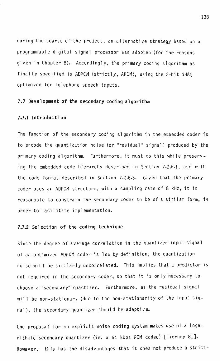
138
during the course of the project, an alternative strategy based on a
programmable digital signal processor was adopted (for the reasons
given in Chapter 8). Accordingly, the primary coding algorithm as
finally specified is ADPCM (strictly, APCM), using the 2-bit GHAQ
optimized for telephone speech inputs.
7.7 Development of the secondary coding algorithm
7.7.1 Introduction
The function of the secondary coding algorithm in the embedded coder is
to encode the quantization noise (or "residual" signal) produced by the
primary coding algorithm. Furthermore, it must do this while preserv
ing the embedded code hierarchy described in Section 7.2.6.1, and with
the code format described in Section 7.2.6.3. Given that the primary
coder uses an ADPCM structure, with a sampling rate of 8 kHz, it is
reasonable to constrain the secondary coder to be of a similar form, in
order to facilitate implementation.
7.7.2 Selection of the coding technique
Since the degree of average correlation in the quantizer input signal
of an optimized ADPCM coder is low by definition, the quantization
noise will be similarly uncorrel ated. This implies that a predictor is
not required in the secondary coder, so that it is only necessary to
choose a "secondary" quantizer. Furthermore, as the residual signal
will be non-stationary (due to the non-stationarity of the input sig
nal), the secondary quantizer should be adaptive.
One proposal for an explicit noise coding system makes use of a loga
rithmic secondary quantizer (ie. a 64 kbps PCM codec) [Tierney 81].
However, this has the disadvantages that it does not produce a strict-

139
ly embedded code (as is explained in Section 7.1 A), and is not neces
sarily well matched to the residual signal statistics, either locally
or in the long term.
Another proposal uses a block coding approach to the quantization of
the residual signal [Jayant 83], While this produces substantial
performance improvements over sequential techniques, it does so at the
expense of considerable extra complexity. Furthermore, as mentioned a
number of times in this thesis, sequential coding is preferred to block
coding in this application.
Another possibility is to use the GHAQ in the secondary coder as well
as the primary coder. However, as speech quality is expected to be
good at the "secondary" coding rates of 32 kbps and higher, a simple
variance-adaptive quantizer is considered adequate. Given this choice,
there are three main design tasks, namely to find a suitable way of
adapting the secondary quantizer, to ensure that its output code is
embedded, and to maximize its SNR, and these issues are discussed
below.
7.7.3 Adaptation of the secondary quantizer
The secondary quantizer is adapted by scaling its levels by a suitable
factor, in order to account for changes in the local variance of the
residual signal. The scaling factor cannot be obtained recursively
from the output of the secondary quantizer itself, because there is no
guarantee that the decoder will have the same information available, as
some of it may be discarded by the channel. The scaling factor must
therefore be derived from some quantity in the primary encoder which is
reasonably well correlated with the variance of the residual signal.

140
Since the GHAQ attempts to preserve an approximately constant SNR,
regardless of the input signal variance, it is to be expected that the
magnitude of its quantization noise will be relatively well correlated
with the signal magnitude. As the GHAQ syllabic factor is an estimate
of the local average magnitude of the input signal, it thus represents
a reasonable scaling factor for the secondary quantizer. However, the
magnitude of the GHAQ output level s(n) is even better in this respect,
as it is an estimate of the most recent input sample, rather than of
the local average, and is therefore less likely to lead to momentary
overload of the secondary quantizer. For this reason, |s(n)| is chosen
as the scaling factor for the secondary quantizer.
Fig. 7.18 shows the structure of the embedded encoder based on explicit
noise coding. (A predictor is shown in the primary coder in this
figure to maintain generality, although it is not used in the imple
mentation described in Chapter 8, due to the fortuitous observation
that the optimum coefficients are zeros, as mentioned in Section
7.6.5.) The dependence of the secondary quantizer on the primary one
is indicated by means of the dashed linkage in Fig. 7.18, and the
output code word w(n) is shown as being formed from its primary and
secondary components, namely wp(n) and ws(n), respectively.
7.7.4 Embedded code generation
One criterion which must be satisfied by an embedded code is that it
should result in successively better approximations to the input sample
as additional code fragments become available to the decoder [Tzou 86].
This is clearly satisfied for the 16 and 64 kbps rates by the structure
of the explicit noise coding scheme, ie. reception of al 1 4 fragments
of a particular code word must result in a better estimate of the input
sample than if only 1 fragment is received. However, as the embedded

141
+ (n) — ^ - J
u(n) i
pV U>7
r(n)
i — *~
\ •
QUANTIZER
QUANTIZER
PRFDI^TrvD
*
*C;
V
> / /
/ s
s(n)
y(n)
•wg(n)
• w (n) ' pv '
w(n)
Fig. 7.18 The embedded encoder based upon explicit noise coding

coder must also support intermediate rates of 32 and 48 kbps, it is
necessary to ensure that the output code of the secondary quantizer
also satisfies the above criterion, and it is not immediately clear
that it wil1.
It has been shown that in order for the output code of a multi-bit
quantizer to be embedded, the decision levels for quantization with F
fragments must form a subset of the set of decision levels for quanti
zation with (F+l) fragments [Tzou 86]. This condition is also known as
"threshold alignment", because the decision levels in the lower-
resolution quantizer are aligned with those in the higher-resolution
one [Tzou 86]. The condition is not satisfied in general when the F-
fragment and (F+l)-fragment quantizers are independently optimized for
maximum SNR. An exception is when both quantizers are constrained to
have uniform level distributions, although this distribution is optimal
for uniform signal PDFs only, and is therefore not appropriate for
speech coding [Jayant 84].
There is thus a conflict between the desire to maximize the SNR for all
coding rates, requiring independent sets of decision levels for each
rate, and the desire for an embedded output code, requiring a single
set of decision levels for all rates. A compromise must therefore be
reached among the SNR degradations incurred at the various rates when a
single set of quantizer decision levels is chosen. One possibility is
to assign equal amounts of SNR degradation to the highest and lowest
bit rates, with no degradation at a "central" bit rate [Tzou 86].
However, in this project it was decided to maximize the SNR at the
highest coding rate, in order to allow the SNR of 64 kbps PCM to be
approached as closely as possible.

143
As regards the quantizer reconstruction levels, it is well known from
the theory of optimum non-uniform quantization that these should be
equal to the centroids of the corresponding quantization intervals if
the SNR is to be maximized [Lloyd 57], [Max 60]. However, the location
of the quantization intervals will depend on the number of fragments of
the embedded code which are received, thus causing a corresponding
variation in the location of the centroids. This implies that separate
sets of reconstruction levels should be used for the various bit rates,
and the use of a single set as in [Tierney 81] is in general sub-
optimal .
7.7.5 Optimization of the secondary quantizer
7.7.5.1 The optimization procedure
According to the discussion in the previous section, optimization of
the secondary quantizer requires a single "compromise" set of decision
levels and four sets of reconstruction levels (one for each rate) to be
found. This can be done using the standard Lloyd-Max optimization
procedure [Lloyd 57], [Max 60], although a "weighted" objective func
tion must be used to take account of the quantizer scaling factor
obtained from the primary coder [Chen 87]. The optimum decision and
reconstruction levels of the secondary quantizer are therefore given
by:
p(k) = 1/2 [ q(k) + q(k-l) ] ; k = 1,2,...,K-1 (7.14)
E{r |s|2|k} q(k) = - ; k = 0,1,...,K-1 (7.15)
E{|s|2|k}
where : p(k) is the decision level associated with level index k
q(k) is the reconstruction level associated with level index k

r is the residual signal from the primary coder
s is the output level from the GHAQ in the primary coder
It should be noted that in this case k is the standard quantizer level
index associated with memoryless quantizers [Jayant 84], and is not
related to the level index used in the GHAQ, as described in Section
7.4.6.3. It is assumed that the residual signal has a symmetrical PDF
about a mean of zero, implying that the optimum quantizer levels will
exhibit similar symmetry.
In order to maximize the SNR at the 64 kbps rate (ie. K - 32), it is
necessary to find the sets of optimum decision and reconstruction
levels for this rate first. Once this has been done, the set of
optimum decision levels is used to calculate sets of reconstruction
levels from (7.15) for the 48 and 32 kbps rates (ie. K = 8 and K = 2).
Due to the zero-mean assumption for the residual signal, the optimum
reconstruction level for the 16 kbps rate is zero.
7.7.5.2 Convergence of the optimization procedure
When a quantizer is optimized with the Lloyd-Max procedure using a
training sequence of input samples, convergence problems may be en
countered when the number of quantizer levels is large. This is first
ly because a finite number of input samples is used, and secondly
because the samples do not change between successive iterations. The
first factor means that the objective function is granular, to a degree
which is determined by the number of samples used. In terms of the
minimization problem, it may be said that the surface of the objective
function is "pitted" with local minima. The second factor means that
these local minima do not shift from iteration to iteration, so that
the procedure may become "trapped" in one of these minima and terminate

spuriously.
While this problem cannot be overcome completely, its effects can be
minimized through the choice of a good starting point for the proce
dure, which reduces the distance which must be traversed to the opti
mum, and therefore decreases the likelihood of spurious termination. A
good starting point also reduces the number of iterations required for
the optimum to be reached, which can be considerable for multi-bit
quantizers.
One way of finding such a starting point is by means of "level split
ting" [Linde 80]. This technique starts with a 1-bit quantizer, which
can be optimized analytically [Jayant 84], and then splits each recon
struction level to form a 2-bit quantizer. The process of splitting a
level amounts to the addition and subtraction of a small constant to
and from the level, thereby forming two new levels. The 2-bit quant
izer is then re-optimized, after which its levels are split to give a
3-bit quantizer, and so on, until the desired quantizer resolution is
reached.
7.7.5.3 Resul ts
The level-splitting technique was applied to the procedure described in
Section 7.7.5.1, in order to find the optimum decision and recon
struction levels for the secondary quantizer. The training sequence
was obtained by applying Sentence 1 in Appendix E to the primary en
coder, and then collecting the residual samples r(n). The reconstruc
tion levels for K = 32, 8 and 2 are given in Table 7.9, and the corres
ponding decision levels can be calculated from (7.14).
Also shown in Table 7.9 are the optimum reconstruction levels calcu
lated without the constraint that the output code must be embedded.

k
0
1
2
3
4
5
6
7
8
9
10
11
12
13
14
15
16
17
18
19
20
21
22
23
24
25
26
27
28
29
30
31
K = 32
0.0143
0.0454
0.0753
0.1039
0.1336
0.1616
0.1950
0.2322
0.2651
0.2959
0.3310
0.3628
0.4278
0.4889
0.5561
0.6262
0.7074
0.7852
0.8678
0.9605
1.0509
1.1412
1.2488
1.3763
1.5352
1.7357
2.0206
2.1875
2.9429
3.7147
8.7802
17.6459
EMBEDDED
q(k)
K = 8
0.0592
0.1841
0.3117
0.5233
0.8303
1.1840
1.7665
3.4271
K = 2
0.2395
1.0164
NON-EMBEDDED
<M
K = 8
0.0572
0.1781
0.3083
0.5112
0.8048
1.1806
2.0210
3.5840
K = 2
0.2275
0.9478
Table 7.9 Optimum embedded and non-embedded reconstruction levels q(k)
for the secondary quantizer

While the differences between the corresponding levels are not substan-
tial in this case, this might not be so for different residual signal
statistics, which might arise if the primary coding algorithm is modi
fied. It was therefore considered advisable to retain the separate
sets of reconstruction levels in the codec implementation described in
Chapter 8. Performance figures for the embedded coder using these
levels are given in Chapter 9.
7.8 Recovery from bit errors
7.8.1 Introduction
In order to allow the voice call path to include low-integrity wide
area networks, the codec should have a reasonable degree of robustness
to bit errors in the channel. Furthermore, such a feature can assist
the decoder in recovering from missing packets, as is discussed in
Section 7.9, as well as in dissipating the effects of different initial
conditions in the encoder and decoder at the start of a call.
In general, a bit error will cause the decoder output to be perturbed
at an one or more sampling times. This error effect can be usefully
separated into "immediate" and "long-term" components. The immediate
effect of a bit error depends on the relative significance of the bit
in the code word hierarchy, which is determined by the shape of the
quantizer characteristic (ie. its level distribution), as well as on
the "weight" assigned to the code word by the coding scheme.
When the quantizer is adaptive, the weight assigned to a code word
changes with time, and is typically correlated with the signal energy.
The "noise" produced by a bit error thus also tends to be correlated in
magnitude with the signal energy, which is desirable if it is required

148
that a constant SNR is maintained. By contrast, when the quantizer is
fixed, as in a 64 kbps PCM coder, the magnitude of the noise due to a
bit error will in general be uncorrected with the signal amplitude,
and for example might stand out as a noticeable click during a low-
energy portion of the signal [Jayant 84].
The long-term effects of bit errors are caused by "memory" in the
coding algorithm. In a general predictive coder, memory might be
present in the quantizer adaptation mechanism, the predictor, and the
predictor adaptation mechanism. In each case, the use of memory is
associated with increased bandwidth efficiency. The degree to which
this memory causes long-term error effects is dependent on the memory
length, and the relative weighting of the individual memory elements.
Recursive algorithms tend to be particularly sensitive in this respect,
due to their (theoretically) infinite memory lengths [Jayant 84].
7.8.2 Effects of bit errors on the primary decoder
Referring to Fig 7.5, the output level of the GHAQ in the primary
encoder is given by:
s(n) = d(n) g(n) (7.16)
where d(n) is the quantizer output level and g(n) is the syllabic
factor. The corresponding quantities in the decoder are:
s'(n) = d'(n) g'(n) (7.17)
The immediate effect of a bit error in the channel will be to perturb
d'(n), and thereby s'(n). The magnitude of this perturbation will
depend on g'(n), and hence on the local average magnitude of the
signal. This dependence of the error effect on the signal magnitude is
desirable, as explained in the previous section.
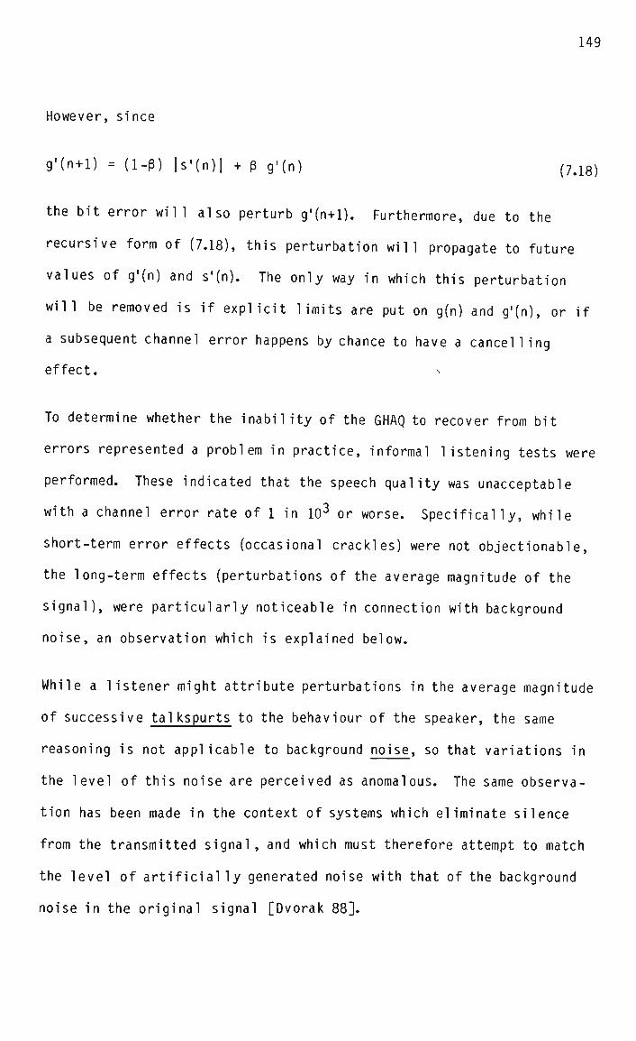
However, since
g'(n + l) = (i-p) |s'(n)| + B g'(n) (7.18)
the bit error will also perturb g'(n+l). Furthermore, due to the
recursive form of (7.18), this perturbation will propagate to future
values of g'(n) and s'(n). The only way in which this perturbation
will be removed is if explicit limits are put on g(n) and g'(n), or if
a subsequent channel error happens by chance to have a cancelling
effect. •<
To determine whether the inability of the GHAQ to recover from bit
errors represented a problem in practice, informal listening tests were
performed. These indicated that the speech quality was unacceptable
with a channel error rate of 1 in IO3 or worse. Specifically, while
short-term error effects (occasional crackles) were not objectionable,
the long-term effects (perturbations of the average magnitude of the
signal), were particularly noticeable in connection with background
noise, an observation which is explained below.
While a listener might attribute perturbations in the average magnitude
of successive tal kspurts to the behaviour of the speaker, the same
reasoning is not applicable to background noise, so that variations in
the level of this noise are perceived as anomalous. The same observa
tion has been made in the context of systems which eliminate silence
from the transmitted signal , and which must therefore attempt to match
the level of artificially generated noise with that of the background
noise in the original signal [Dvorak 88].

150
7.8.3 The development of the robust GHAQ
It is clear from the previous section that the inclusion of a specific
error-recovery mechanism in the GHAQ in the primary coder is necessary,
if satisfactory performance is to be obtained with non-ideal channels.
Two such mechanisms which have been successfully applied to other
adaptive quantizers were considered for this purpose. The first is the
"exponential leakage" technique used in the Robust Adaptive Quantizer
(RAQ) [Goodman 75], which is essentially a modified form of the Jayant
Adaptive Quantizer (JAQ) [Jayant 73]. In the RAQ, exponential leakage
is applied to the quantizer step size at each sampling instant. The
quantizer adaptation mechanism is thus given by:
A(n) = A(n-1)Y M(w(n-1)) (7.19)
where : A(n) is the quantizer step size
Y is the leakage constant
M(w(n-1)) is the step size multiplier
w(n-l) is the previous quantizer output code word
It has been shown that for y< 1. the effect of channel bit errors on
the quantizer step size in the decoder is dissipated with time [Goodman
75]. Furthermore, the recovery process is independent of the statis
tics of the input signal. However, the increase in implementation
complexity over the JAQ (ie. y = 1) is significant.
The second error recovery mechanism considered here, which has been
successfully used in an ADM coder, involves the addition of a small
constant to the quantizer step size at each sampling instant [Dodds
80]. This scheme is much simpler to implement than the exponential
leakage algorithm, but has the disadvantage that the speed of recovery
is dependent on the input signal statistics. Specifically, recovery

151
takes longer when the average magnitude of the signal is large [Dodds
80]. The recovery time can be shortened by increasing the magnitude of
the step size increment, but only at the expense of a reduced SNR
during low-level portions of the input signal.
In this case, the quantizer adaptation mechanism is given by:
A(n) = A(n-l) M(w(n-1)) + I (7.20)
where : A(n) is the quantizer step size
I is the step size increment
M(w(n-1)) is the step size multiplier
w(n-l) is the previous quantizer output code word
The recovery mechanism of (7.20) is considered more suitable for this
project than that of (7.19), due to its considerably simpler implement
ation. Also, the fact that error rates greater than 1 in IO3 are not
expected means that a relatively small step size increment can be used,
thereby avoiding significant SNR degradation for low-level signals.
As the syllabic factor in the GHAQ corresponds to the step size A(n) in
(7.20), a "syllabic increment" I is used in this application, instead
of a step size increment. The syllabic increment is added to the input
of the syllabic compandor, as shown in Fig. 7.19, so that the syllabic
factor in the resulting "robust" GHAQ is calculated as follows:
9(n) = (1-B) [|s(n-l)| + I] + B g(n-l) (7.21)
It is not immediately obvious why the addition of the syllabic incre
ment should cause the effects of channel errors on the syllabic factor
to dissipate. An intuitive explanation given in [Dodds 80] is that it
causes an increase in the probability of the selection of quantizer
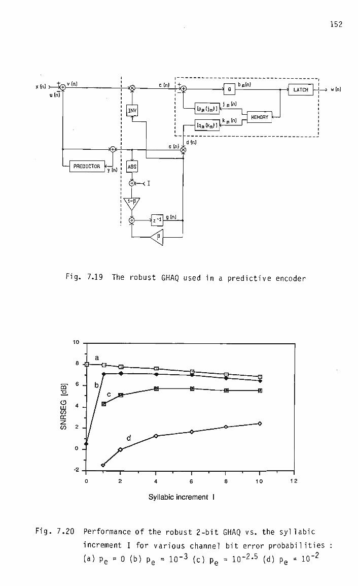
x (n) >—fe>-v (n!
u(n)
PREDICTOR i
w(n)
Fig. 7.19 The robust GHAQ used in a predictive encoder
Syllabic increment I
Fig. 7.20 Performance of the robust 2-bit GHAQ vs. the syllabic
increment I for various channel bit error probabilities
(a) p e = 0 (b) p e = IO"3 (c) p e = 10"2'5 (d) p e = 10"2

153
reconstruction levels which have magnitudes less than unity. This
causes the feedback path between the output and input of the syllabic
compandor (ie. between g(n) and s(n) in Fig. 7.5) to have an average
"gain" less than unity, so that perturbations of the syllabic factor
are leaked away with time. A more rigorous explanation of error recov
ery in the robust GHAQ is given in Appendix B.
7.8.4 Performance of the robust GHAQ
As observed in the previous section, the selection of a suitable value
for the syllabic increment involves a trade-off between the SNR with an
error-free channel on the one hand, and the SNR with channel errors on
the other. Furthermore, the effect of the bit error recovery mechanism
is greater on low-level signals than on high-level signals. The com
plex nature of this trade-off makes it difficult to identify a clear
"optimum" for the syllabic increment. Fortunately, however, the per
formance of the robust GHAQ is not very sensitive to the exact value of
this parameter.
This is illustrated in Fig. 7.20, where SNRSEG is plotted against the
value of the syllabic increment, with the channel error rate as a
parameter. (The units of the syllabic increment are 1/4095 of the
maximum signal magnitude.) SNRSEG, rather than SNR, is used as a
performance measure in this case for two reasons. Firstly, it is known
that SNR is a poor indicator of the quality of ADPCM coders under noisy
channel conditions, and that SNRSEG is significantly better in this
respect [Scagliola 79]. Secondly, the effect of the bit error recovery
mechanism is greater on low-level than on high-level signals, and these
low-level signals tend to be more fairly weighted in the SNRSEG mea
sure.

Curve (a) in Fig. 7.20 shows that the performance of the robust GHAQ
with an error-free channel degrades gradually as the syllabic increment
is increased, which can be attributed to increasingly sub-optimal
estimation by the syllabic compandor of the average magnitude of the
signal. The large effect of an error rate of 1 in IO3 on the perform
ance of the "non-robust" GHAQ (ie. I = 0) is evident from curve (b),
confiriming the need for the bit error recovery mechanism.
At a higher error rate, (1 in IO2*5) the performance improves as the
syllabic increment is increased, until a saturation level is reached,
as can be seen from curve (c). Given that error rates in excess of 1
in IO3 are not expected in this application, a reasonable choice for
the syllabic increment is between about 1 and 4.
7.8.5 Idle channel noise in the robust GHAQ
Another issue which must be considered in choosing a value for the
syllabic increment is that it determines, in combination with the
smallest quantizer reconstruction level, the minimum output level of
the robust GHAQ. The relationship between these three quantities is
shown in Appendix C to be:
1 drnin ti oo\
U - dmin)
where : I is the syllabic increment
dm1-n is the smallest quantizer reconstruction level
sml-n is the minimum output level of the robust GHAQ
The minimum output level of the robust GHAQ is of interest because it
determines the "idle channel noise", ie. the decoder output when the
input to the encoder is zero or close to zero. (The GHAQ has a

155
"midrise" quantizer characteristic, which means that it reconstructs
zero or near-zero amplitudes using a small non-zero level [Jayant 84].)
For example, for the idle channel noise to have an amplitude no greater
than 1, and assuming that the minimum quantizer reconstruction level
dml-n is 0.5, then from (7.22) the maximum permissible value of the
syllabic increment I is also 1.
7.8.6 The effects of bit errors on the secondary decoder
As the secondary decoder itself contains no memory, bit errors which
corrupt secondary bits in the embedded code words will have only short-
term (spike-like) effects on the secondary decoder output. The magni
tude of these spikes will depend on the significance of the affected
bit within the code word hierarchy, as well as on the weight assigned
to the code word by the quantizer scaling factor, as discussed in
Section 7.8.1. While it is possible to use smoothing techniques to
remove spikes from the decoder output [Jayant 84], this is unlikely to
be worthwhile at the error rates expected in this case.
Bit errors which corrupt primary bits of the embedded code will also
affect the secondary decoder output, through perturbations in the GHAQ
output level s'(n), which is used to adapt the secondary quantizer.
However, making the GHAQ robust to such errors, as described in Section
7.8.3, will also reduce their effects on the secondary decoder output.
7.9 Recovery from missing packets
7.9.1 Introduction
A packet may be missing from the received stream due to being silent or
lost. In either case, it is the task of the packet fill-in algorithm
to replace the missing packet with substitute code, so that the decoder
156
sees a continuous code stream. However, a side-effect of the missing
packet is that with adaptive coding algorithms the decoder is likely to
lose track of the encoder, as in the case of channel bit errors.
Whereas bit errors may occur at arbitrary points in the code stream,
missing packets may only occur at known points, corresponding to packet
boundaries. Furthermore, whereas bit errors may be scattered, and
hence cause "diffused" mistracking effects, missing packets are equiva
lent to concentrated error bursts of considerable duration (typically
10 - 20 mS), implying the probable loss of a significant amount of
tracking information.
While mechanisms developed to enable adaptive coding algorithms to
recover from channel bit errors will also lead to eventual recovery
from missing packets, this may take a substantial length of time. For
example, using the Robust Adaptive Quantizer (RAQ) with exponential
leakage (described in Section 7.8.3), a burst of 60 bit errors in 255
successive code words can cause a decoder error which takes a further
400 sample periods to dissipate [Yatrou 88]. (While the coder in this
example also makes use of backward adaptive prediction, it is stated in
[Yatrou 88] that the decoder error is attributable mainly to mistrack
ing in the adaptive quantizer.) When the code words in a packet are
missing altogether (as opposed to merely corrupted), the potential
error effect is even greater.
7.9.2 The effect of missing packets on the embedded decoder
In the embedded decoder of this project, information related to the
signal history is present in the primary decoder only. Specifically,
it is contained in the bits b'Q(n-l) and b'^n-1) in the GHAQ memory,
and in the syllabic factor g'(n). The absence of b'0(n-l) and b'^n-1)

157
after a missing packet is equivalent in the worst case to a pair of bit
errors. Assuming a packet size of 256 bits (16 mS at 16 kbps) and a
missing packet rate of 1 in 100, this amounts to a bit error rate of
about 1 in 10 . However, according to the results of Section 7.8.4,
this will cause little degradation of the performance of the robust
version of the GHAQ.
Of more concern is the probable loss of tracking between g(n) in the
encoder and g'(n) in the decoder. If a packet is missing because it
was eliminated due to being silent, then the mismatch between g(n) and
g'(n) is likely to be negligible if g'(n) is simply held fixed for the
duration of the missing packet. However, when the packet is missing
due to being lost, then the mismatch produced by this strategy might be
considerable. As a packet period of 16 mS corresponds to 128 sampling
periods of 125 uS, it is possible for the encoder syllabic factor to
change substantially in magnitude over the course of a missing packet.
For example, in the 14 sampling periods taken to reach the step level
in the step response of Fig. 7.17, g(n) increases by a factor of about
3.
7.9.3 A mechanism for recovering from missing packets n
The fact that missing packet effects can only manifest at packet bound
aries, rather than at arbitrary points in the code stream, makes it
feasible to transmit side information in each packet which will assist
with the re-establishment of tracking in the event that the preceding
packet is missing at the receiver. As it is shown in the previous
section that the most important quantity in this respect is the sylla
bic factor in the GHAQ, provision is made for this variable to be re
initialized in the decoder to a value provided by the receiver's net
work voice protocol.

158
This also requires that the syllabic factor in the encoder is made
available to the transmitter's network voice protocol at the approriate
time, so that it can be included in each packet. It is worth noting in
this connection that the syllabic factor is also used by the network
voice protocol for prioritization purposes, as is discussed in Section
7.11.4.
7.10 Packetization issues
The embedded encoder produces code words containing fragments with four
different levels of significance. However, embedded coding is most
useful in a packet switched network if code fragments of equal signifi-
cance are grouped together during the packetization process. This
means that network flow control may be performed by discarding entire
packets at a time. As requiring the network voice protocol to group
the code fragments appropriately places a substantial burden on the
workstation's processor, this task is given to the codec instead.
The packetization of the embedded code fragments is illustrated in Fig.
7.21. The specific example used in this figure is a fragment with
significance 0, but the packetization of fragments with significance 1,
2 and 3 is exactly analogous. As can be seen, significance 0 fragments
from four successive sampling periods are grouped into a single byte.
These bytes are then formed into a packet of the desired length, so
that the packet contains only fragments of a particular significance.
(An implication of this approach is that the packet period must be
equal to a multiple of four sampling periods, ie. of 500 uS.)
Once this process is complete, the network voice protocol simply has to
make a transmit/discard decision for each packet, using the associated

f3(n) t>(n) ^(n) f0(n)
Mn) bQ(n)
f0(n-3) f0(n-2) f0(n-D f0(n)
EMBEDDED CODE WORD w(n)
SIGNIFICANCE 0 FRAGMENT
SIGNIFICANCE 0 BYTE
HEADER
SIDE INFORMATION
SIGNIFICANCE 0 CODE
SIGNIFICANCE 0 CODE
SIGNIFICANCE 0 CODE
BYTE
BYTE
BYTE
SIGNIFICANCE 0 CODE BYTE
SIGNIFICANCE 0 PACKET
Fig. 7.21 Packetization of an embedded code fragment with
significance 0

160
prioritization and flow control information, and append side informa
tion and packet headers as appropriate.
The fact that the packetization process is under the control of the
codec implies that the packet length cannot be varied instantaneously
according to the access delay experienced by each packet. However, at
the end of every packet generation period, the network voice protocol
has a chance to set the length of the next packet, so that long-term
adaptation of the packet length to changing network conditions is still
possible. As described in Section 5.2, this approach is likely to
cause fewer problems in the synchronization process at the receiver
than instantaneous variations in the packet length.
7.11 Prioritization and flow control issues
7.11.1 Introduction
In general, the network voice protocol assigns a priority to a packet
of speech code on the basis of the source activity, the degree of
transmission success achieved by previous packets in the call, and the
relative requirements of data packets. Attention is restricted here to
the first factor, as this is of specific concern in the design of the
codec, which is required to supply the network voice protocol with
suitable prioritization information.
The flow control algorithm uses the packet priority, as well as inform
ation supplied by the load prediction algorithm, to decide whether an
attempt should be made to transmit the packet. As the formatting of
voice packets to facilitate flow control has already been described in
Section 7.10, no further attention is given here to the flow control
issue. However, implicit in the discussion of the prioritization
algorithm below is the assumption that the flow control algorithm will

161
discard (as opposed to queue) voice packets which it decides are not
important enough to transmit immediately.
7.11.2 Speech prioritization in DCM systems
Speech prioritization is used in DCM systems not only to allow effi
cient concentration through silence elimination, but also to identify
information which can be discarded in overload situations when variable
rate coding is used, as described in Section 7.2.2. Two main types of
prioritization scheme have been described in the literature, namely
"signal-based" and "coder-based" types.
Signal-based schemes use properties of the input signal as the basis of
prioritization. Included in this category are the tal kspurt/silence
discrimination schemes used in traditional TASI systems, which are
usually based on a measurement of the local average signal energy
[Drago 78]. More recently, higher resolution prioritization using
spectral properties of the signal has been described [Yatsuzuka 82].
In this approach, the number of bits with which each sample is quant
ized is dependent not only on the signal energy, but also on whether
the signal is classified as a "wideband" or a "narrowband" sound, the
former being assigned more bits/sample than the latter. The reasoning
behind this is that wideband sounds are less predictable than narrow
band ones, and are therefore less well coded by ADPCM algorithms
[Yatsuzuka 82].
Coder-based prioritization schemes, on the other hand, vary the coding
rate according to the performance of the coder, rather than according
to the properties of the signal. For example, a common approach is to
attempt to maintain a constant coding SNR for all types of sound [Lang-
enbucher 82]. Obviously, coder-based prioritization schemes have the

162
potential to be more effective than signal-based ones, as it is the
decoded signal that the listener actually hears, rather than the en
coder input signal. However, in practice this advantage is dependent
on how well the performance measure used is correlated with perceptual
speech quality.
7.11.3 Fixed-rate performance of the embedded coder
In order to develop a scheme for varying the number of bits assigned to
various portions of the input signal, it is necessary to evaluate the
performance of the embedded coding algorithm at each individual bit
rate. Informal listening tests were therefore conducted, with the
fol lowing resul ts:
At 16 kbps, good intelligibility was observed, but distortion was
noticeable in all types of sound. This "roughness" was most
noticeable in sounds with substantial high-frequency content,
particularly fricatives.
At 32 kbps, slight distortion was audible in high-frequency
sounds.
At 48 and 64 kbps, no distortion was audible in any type of sound.
A significant aspect of the above observations is the discrepancy
between the perceptual performance for low and high-frequency sounds.
This might be explained by the fact that the fixed predictor coeffi
cients (which happen to be zeros in this case) are calculated using
long-term average statistics of the signal, implying that in the short
term significant mismatch may exist between the signal and predictor.
As voiced (low-frequency) sounds are more prevalent than unvoiced
(high-frequency) sounds in speech [Jayant 84], the long term average

statistics will be dominated by the former, with the result that the
coding of unvoiced sounds will be less accurate [Evci 1981]. However,
informal listening tests with a prioritization scheme which attempted
to maintain a constant SNR for all sounds (as in Section 7.11.2) were
not encouraging, and suggested that some factor other than SNR needed
to be considered.
An investigation of the spectral properties of the signal and coding
noise was therefore undertaken. In Figs. 7.22 and 7.23, the spectra of
the signal and quantization noise are shown for the coding of a voiced
and an unvoiced sound by the primary coder. The voiced sound is the
"AA" in "dark", and the unvoiced sound is the "SH" in "sheet", the
utterance involved being Sentence 1 in Appendix E. It can be seen that
in both cases the noise spectrum is substantially flat, apart from
minor deviations, as is to be expected in APCM systems [Jayant 84].
In the case of the voiced sound (Fig. 7.22), there is a predominance of
low-frequency energy, but it is important to note that at higher fre
quencies the noise power does not significantly exceed that of the
signal. (An exception to this is at the extreme high end of the
spectrum, where the signal power decreases rapidly. This is due to the
roll-off above 3.4 kHz of the pre-sampling filter, and as the recon
struction filter has a similar roll-off, the noise power will be simi
larly reduced at the earphone.)
In the case of the unvoiced sound in Fig. 7.23, there is a predominance
of high-frequency energy, and at lower frequencies the signal power
drops considerably below the noise power. It is well known that coding
noise is more objectionable if its power significantly exceeds that of
the signal in any part of the spectrum within the signal band [Jayant

164
-0 TS
a u N M
J O
z
" flfl"
FREQUENCY D0MRIN MRG SOURRED DRTFI
POINTS NORMALIZED db: 0= B.037 5E+001 db FREQUENCY RESOLUTION «= 6.E500E+01 Hz FOLDOVER FREQUENCY = 4.0000E+03 Hz = POINT
— i
G4
64
Fig. 7.22 Signal and coding noise spectra for the primary coder with a
voiced sound
" S H " FREQUENCY DOMRIN MRG SQURRED DRTfl
POINTS NORMALIZED db: 0= 8.4G05E+001 db FREQUENCY RESOLUTION - 6.2500E+01 Hz FOLDOVER FREQUENCY = 4.0000E+03 Hz = POINT
— i
G4
64
Fig. 7.23 Signal and coding noise spectra for the primary coder with
an unvoiced sound.
165
84]. This is the basis of the Noise Feedback Coding (NFC) technique,
in which the quantization noise spectrum is purposely re-shaped so that
it follows that of the signal, and is therefore perceptually "masked"
[Jayant 84]. Referring again to Fig. 7.23, the fact that the noise is
"exposed" in the low frequency region makes it more noticeable than
would otherwise be the case, thus further degrading the speech quality
obtained for unvoiced sounds.
The question naturally arises as to whether the reverse situation might
occur, ie. whether a voiced sound might produce a significant degree of
exposed noise in the high frequency region. This was not found to
occur in practice, an observation which may be attributed to the pre-
emphasis of the input signal performed by the telephone microphone,
which flattens the "low-pass" spectrum conventionally associated with
voiced sounds.
It is thus indicated that the speech coding rate should be increased
for sounds which have a predominance of high-frequency energy, which
will decrease the noise power across the entire spectrum in Fig. 7.23,
thereby reducing the amount of exposed noise. This approach is con
sistent with the increased number of bits allocated to unvoiced sounds
in some DCM systems based on ADPCM [Cox 80], [Yatsuzuka 82].
7.11.4 Generation of the prioritization variables
Clearly, an important prioritization variable is the local average
energy of the input signal, as the priority of low-energy pauses must
be made lower than that of high-energy talkspurts. This does not
necessarily imply that there should be a linear relationship between
the signal energy and the transmission priority, as this might en
courage users to speak more loudly in order to claim more transmission

166
bandwidth! Nevertheless, as far as the codec is concerned, the genera
tion of some quantity related to the local average signal energy is
required, the exact way in which this information is used being left to
the network voice protocol.
Since the primary coder already generates such a quantity, namely the
syllabic factor of the GHAQ, it makes sense that this is transferred to
the network voice protocol for prioritization purposes. Furthermore,
this fits in with the need to transmit the encoder syllabic factor to
the decoder to aid in the recovery from packet loss, as described in
Section 7.9.3.
The discussion in the previous section indicates that it is also nece
ssary to discriminate between voiced and unvoiced sounds for prioriti
zation purposes. A well-known means of doing this is to estimate the
zero crossing rate of the input signal, a high rate indicating a high
frequency (unvoiced) sound [Rabiner 78]. Although this technique is
only approximate, it is considered sufficient for this application,
particularly since prioritization takes place only on a per-packet
basis, and is therefore inherently limited in precision.
The use of the zero crossing rate for prioritization is also consistent
with the need to assign a higher priority to talkspurts than to sil
ence, as high-frequency consonants (such as the "s" in "stop") freq
uently have a low energy, and are therefore not given a sufficiently
high priority by energy-based schemes [Rabiner 78].
The zero crossing rate estimate is generated by the codec as follows.
Successive output code words from the primary encoder are examined, a
reversal of the sign bit indicating that the signal has crossed the
zero axis. In this case a counter is incremented, but if no sign

167
reversal is observed, the counter is decremented. The value in the
counter is referred to as the "zero crossing count". Due to the way in
which it is generated, the zero crossing count tends to be close to
zero for voiced sounds and close to its maximum value for unvoiced
sounds, spending little time between these limits.
The distinct types of behaviour of the two prioritization variables are
shown in Figs. 7.24 and 7.25, which were generated using Sentence 1 in
Appendix E. The syllabic factor g(n) simply follows the local signal
energy as expected, whereas the zero crossing count in Fig. 7.25 dis
criminates between the significant burst of high frequency energy in
the word "sheet" and the predominance of low frequency energy in most
of the rest of the sentence.
7.11.5 Use of the prioritization variables
The portion of the prioritization algorithm which takes account of the
source activity should be of the following form:
P = f(S,G,Z) (7.23)
where : P is priority
S is the significance of the code fragments in the packet
G is the maximum syllabic factor associated with the packet
Z is the maximum zero crossing count associated with the packet
f(*) is some function
A suitable form for f(S,G,Z) needs to be determined, and is a subject
for future research, although it can be stated at this stage that it
should be an increasing function of S, G, and Z. This will mean that
the highest priority will be assigned to a packet containing the most
significant fragments of code associated with high-level, high-

250 -
200
C
cn
150
100
50
168
GLUE THE SHEET TO THE DARK BLUE BACKGROUND
-L_ i <J
5000 10000 n
u VJ J — . i . . i 15000 20000
Fig. 7.24 Plot of the syllabic factor g(n) over the course of a
sentence
GLUE THE SHEET TO THE DARK BLUE BACKGROUND
T
20000
Fig. 7.25 Plot of the zero crossing count over the course of a
sentence

169
frequency sounds, and the lowest priority to a packet containing the
least significant fragments of code associated with low-level, low-
frequency sounds. (Maximum values of the syllabic factor and zero
crossing count are specified above, in order to ensure that a high
priority is given to packets in which only a small portion of the code
is associated with a "high-priority" sound.)
In addition, the following guidelines are suggested from informal
1istening tests:
The best subjective quality is obtained if al 1 portions of the
speech signal are transmitted, including intervals of so-called
silence. This implies that f(G,S,Z) should never produce a prior
ity of zero.
Transmitting any type of speech sound at a bit rate greater than
48 kbps produces no audible quality improvement. (While this
seems to imply that the 64 kbps coding rate is redundant, this
rate might nevertheless be useful in special cases where the SNR
of the signal is degraded considerably in the transmission chan
nel , due for example to a large number of asynchronous tandem
coding operations.)
Transmitting silence (ie. background noise) at a bit rate greater
than 16 kbps produces no audible improvement.
Talkspurts (detected by means of the syllabic factor) should be
transmitted at a higher bit rate than silence, an appropriate rate
increment being 16 kbps.
Unvoiced sounds (detected by means of the zero crossing count)
should be transmitted at a higher bit rate than voiced sounds, an

170
appropriate rate increment being 16 kbps.
7.12 Packet voice synchronization and fill-in issues
7.12.1 Synchronization
The embedded coder design places a few minor restrictions on the type
of synchronization algorithm which can be used in the network voice
protocol. Firstly, as the decoder sampling rate is fixed, receive
buffer management must be done on the basis of code insertion and
discarding, rather than sampling rate adjustment. Secondly, because
the coding algorithm is adaptive, samples within a particular packet
are dependent on each other, so that where code is discarded, this
should be either an entire packet or the tail-end of a packet. If the
front-end of a packet is discarded, an error will be produced in the
decoder syllabic factor.
The codec is thus suitable for use with the packet voice synchroniza
tion algorithm described in Section 5.5.3.4, which adapts to the packet
delay statistics on the basis of the observed arrival times, by in
creasing or decreasing the packet synchronization delay in units of a
packet period. As mentioned in Section 5.5.4, such an algorithm is
recommended in this application.
7.12.2 Fill-in
A number of features are included in the codec design in order to
facilitate the implementation of the simpler packet voice fill-in
strategies described in Section 5.6.2 (ie. the insertion of silence,
random noise or the contents of the previous packet). While further
experimentation is required to determine the perceptually optimal fill-
in strategy for the embedded codec with given packet loss statistics,

171
the features described below provide considerable flexibility in this
regard.
Firstly, the decoder syllabic factor can be explicitly set to a parti
cular value by the fill-in algorithm, implying that the average magni
tude of the fill-in signal can be easily manipulated. For example, an
appropriate level for random noise can be determined from the syllabic
factor of the previous packet and set accordingly, thereby improving
the matching between the substitute packet and adjacent packets.
If the contents of the previous packet are used as a substitute, then
the decoder syllabic factor can be re-initialized to its value at the
start of the previous packet, to ensure that the signal at the decoder
output is a replica of that associated with the previous packet. If
this were not done, repetition of the code in the previous packet would
in general produce a different decoder output signal, due to the diff
erent initial state of the adaptive quantizer.
Secondly, provision is made to "freeze" (ie. not update) the decoder
syllabic factor for the duration of a packet. This means that the
average magnitude of the decoder output can be held constant, regard
less of the substituted code. This feature can be used to ensure that
digitally synthesized random noise does not cause the decoder syllabic
factor to grow or decay with time.
Thirdly, a decoding rate of "zero" kbps can be selected. This simply
replaces the decoder output with zero-valued samples, regardless of the
actual speech code involved, and means that silence can be inserted
without copying special code into the receive buffer.
Finally, provision is made for the embedded decoding algorithm to be
bypassed, so that the substitute code can be in PCM form. This feature
172
is useful if the fill-in signal cannot be conveniently represented in
embedded code form.

173
CHAPTER 8 : IMPLEMENTATION OF THE CODEC
8.1 Introduction
In this chapter, a real-time implementation in digital hardware of the
embedded codec developed in Chapter 7 is described. Interface and
control circuitry associated with the transfer of information between
the codec and the network voice protocol is also discussed, and the
format of this information is specified.
8.2 Implementation strategy
It was originally proposed that the codec be implemented by integrating
it onto a number of digital gate arrays and analog uncommitted chips.
At the time of the proposal (January 1984), this seemed the only feas
ible strategy, as general-purpose microprocessors did not have the
speed necessary for real-time speech coding, and the specialized Digi
tal Signal Processors (DSPs) which were beginning to emerge were either
prohibitively priced or too slow for this application.
Since then, however, the cost of DSPs has reduced to the point where
their use in this project became reasonable. Apart from the relative
ease with which complex signal processing functions may be implemented
using these devices, the fact that they are programmable means that
modifications and improvements may be made to the coding algorithm at a
later date.
8.3 An overview of the codec card
The speech coding system is implemented on a printed circuit expansion
card for the IBM PC (Fig. 8.1), referred to here as the "codec card".
A block diagram of the circuitry on the card is given in Fig. 8.2.

Fig. 8.1 Photograph of the codec card
r
L
HOO SWITC
K ft ;H "
PCM CODEC/ FILTER
DIGITAL SIGNAL
PROCESSOR
CONTROL REGISTER
DMA CONTROLLER
MEMORY
MEMORY ACCESS
ARBITRATOR
•4-*
CO
CD
o Q.
Fig. 8.2 Block diagram of the circuitry on the codec card
175
This circuitry performs four essential functions. Firstly, signal
conditioning and conversion is performed by analog amplifiers and a PCM
codec/filter chip. Secondly, the embedded coding algorithm and asso
ciated operations are implemented by a digital signal processor.
Thirdly, the transfer of speech code and associated information between
the codec and the network voice protocol is performed by a shared-
memory interface. Finally, the operation of individual card elements
is co-ordinated by means of a card control/status register.
8.4 Signal conditioning and conversion
The input signal from the handset mouthpiece is high-pass filtered by a
first-order RC filter with a lower cutoff frequency of 190 Hz, to
prevent 50 Hz mains "hum" picked up by the handset lead from reaching
the earpiece via the sidetone path. The signal is then amplified by 35
dB before being fed into the PCM filter/codec IC. Further gain of up
to 20 dB (variable by means of a trimpot) is applied to the signal
within the PCM codec. A fraction of the input signal (variable between
0 and 1 using a trimpot) is also added to the output signal from the
PCM codec/filter chip, in order to provide the sidetone. The gain of
the composite output signal can be varied between -«°and 0 dB (using a
trimpot) before it reaches the handset earpiece.
The PCM codec/filter chip performs the pre-sampling and reconstruction
filtering, with a standard signal band of 300 - 3400 Hz. Conversion
between analog and digital forms is also performed, and the digital
code is 8-bit, sign-magnitude, A-law PCM.

176
8.5 The embedded codec
8.5.1 Choice of digital signal processor
The DSP used to implement the embedded codec is the Texas Instruments
TMS320E17, a variant of the TMS32010. Features of this device which
make it particularly suitable for this application are a serial PCM
interface, logarithmic companding hardware, a latched "coprocessor"
port, and a relatively low cost.
The serial PCM interface facilitates the use of a PCM filter/codec chip
for signal filtering and conversion, and the companding hardware allows
log PCM code to be linearized for signal processing purposes without
the use of time-consuming software. The latched coprocessor port
allows the asynchronous exchange of data between the DSP and the card's
shared memory, thus avoiding the reduction in the speed of program
execution which would result if the program had to wait for memory
accesses to be completed.
8.5.2 Program structure and timing
The DSP program is written in TMS32010 assembly language, and is con
tained in an EPROM which is part of the device itself. The program
consists of an initialization section, an interrupt handler, and a main
routine, as shown in Fig. 8.3. (Subroutines are avoided because of the
processing overhead associated with the call/return sequence.) The
initialization section is executed when the DSP is reset, and the
interrupt handler is associated with real-time synchronization, as
explained below.
The main routine contains the transmit and receive functions associated
with a single sampling period, ie. 125 uS. (The "transmit" direction

177
C RESET " )
INITIALIZATION
MAIN ROUTINE
FRAMING PULSE
INTERRUPT i
INTERRUPT HANDLER
Fig. 8.3 DSP program flow chart

178
is defined to be from the mouthpiece to the network, and the "receive"
direction is from the network to the earpiece.) The transmit functions
include fetching a PCM input sample from the serial port and encoding
it into embedded form, as well as generating speech prioritization
information. In addition, a transmit buffer inside the DSP, which is
required to allow formatting of the embedded code as is described in
Section 8.5.4, must be managed. The receive functions include decoding
an embedded code word and sending the result to the PCM codec via the
serial port, as well as managing an internal receive buffer.
Apart from executing the transmit and receive functions, it is also
necessary for the codec to maintain synchronization with the 125 uS
sample "framing pulse" associated with the PCM codec. This obviously
requires that the main routine executes in less than 125 uS, which
corresponds to 625 cycles of the DSP's clock. Synchronization is
maintained by tying the framing pulse to a DSP interrupt, rather than
by means of polling. This approach has the advantage that any viola
tion of the 125 uS period, due for example to a software modification,
is easily detected.
The 125 uS period during which one sample is encoded/decoded is re
ferred to as a "sample cycle", and is subdivided into "active" and
"inactive" phases. During the active phase, the transmit and receive
functions in the main routine are executed, and during the subsequent
inactive phase the DSP sits in an idle loop waiting for the next
framing pulse. Thus as the processing time required by the active
phase of the sample cycle tends to 125 uS (see Section 8.5.5), the
duration of the inactive phase will tend to a minimum.
While information is transferred between the DSP and the PCM codec on a
sanple-by-sample basis, the exchange of information between the DSP and

179
the card memory is done on a "group" basis. This is necessary because
of the way that the embedded code words are formatted into bytes, as is
described in Section 8.5.4. A "group cycle" equal to four sample
cycles (ie. 500 /JS) is thus defined. During a group cycle, four suc
cessive samples are encoded (and decoded). The code, as well as asso
ciated control information, is formatted into an 8-byte group, which is
stored in an internal transmit buffer in the DSP itself before being
transferred to the card memory. A corresponding operation also takes
place in the receive direction. The composition of the transmit and
receive groups is described in Section 8.5.4.
8.5.3 Arithmetic considerations
8.5.3.1 Fixed-point notation
The fundamental wordlength of the TMS320E17 DSP is 16 bits (this is the
length of most registers and all memory locations), although 32-bit
arithmetic can be performed in the accumulator. Since linearized A-law
PCM code requires 13 bits (including the sign bit) for its representa
tion, a natural notation is Q3, ie. 13 whole bits and 3 fractional bits
[Texas Instruments 85]. This implies a representational accuracy of
+/- 0.0625 "linear units", where one linear unit is the weight of the
LSBit of the linearized PCM sample. For this reason, most variables in
the coding algorithm are represented in Q3 form. As two's complement
arithmetic is used, conversion to and from the sign-magnitude notation
used by the PCM codec is required.
Some quantities in the coding algorithm, such as the secondary quan
tizer levels, require a higher representational accuracy than that
provided by Q3 notation. Careful choice of the notation in these cases
minimizes the number of instructions required to convert non-Q3 pro-
180
ducts to Q3 form after multiplication operations. For example, repre
senting the secondary quantizer levels in Q12 notation means that a Q15
product is formed after multiplication by the scaling factor from the
primary coder, which is a Q3 quantity. This 32-bit Q15 product can
then be converted back to a 16-bit Q3 quantity with a single shift-
right-by-4-and-store instruction. As only shifts of 0,1 or 4 places
can be specified in this instruction [Texas Instruments 85], the need
for care in selecting the notation of the quantities involved is clear.
8.5.3.2 Arithmetic overflow
Arithmetic overflow is avoided through the use of appropriate scaling,
and an explicit upper limit on the syllabic factor in the primary
coding algorithm. Also, the TMS320E17's "arithmetic saturation" func
tion is enabled, which causes overflow results in the accumulator to be
replaced by the largest number which can be represented.
8.5.3.3 Truncation error
Another issue in the choice of notation is the effect of truncation
error on the long-term operation of the coding algorithm. This is
often important when recursive structures are used in digital signal
processing applications, as truncation errors can then accumulate. In
this project, only the primary coder contains such a structure, namely
the syllabic compandor in the GHAQ. However, in this case the use of
feedback tends to compensate for truncation errors in the same way as
it compensates for quantization errors, as discussed in Section
7.4.10.2. Truncation error is thus not expected to affect the SNR of
the codec significantly, and this was confirmed experimentally by
comparing the performance of the simulated codec (which used floating
point arithmetic) with the DSP version. With the same input sequence

181
(Sentence 1 in Appendix E), the respective SNR and SNRSEG figures
differed by at most 0.1 dB.
However, in contrast to the above, the ability of the codec to recover
from channel errors is not protected from the effects of truncation by
the use of feedback. As discussed in Section 7.8.3, the "robust" GHAQ
derives its robustness from the addition of the syllabic increment
which is applied to the input of the syllabic compandor. Suitable
values for this increment are shown in Section 7.8.4 to be in the
region of 1 - 4. As this increment is then scaled by a factor (1-0) =
0.06 (see Fig. 7.5), it is in danger of being truncated out of exist
ence in a Q3 quantity.
For this reason, B is changed in the codec implementation from 0.94 to
0.9375, which according to Fig. 7.10 has negligible effect on the
performance of the 2-bit GHAQ. The term (1-B) then becomes equal to
0.0625, which corresponds to an arithmetic right shift of 4 places, as
opposed to more than 4 in the case of (1-B) = 0.06. In addition, the
syllabic increment is made equal to 2, ensuring that it will not dis
appear from a Q3 quantity after being shifted right by 4 places. The
effect of these two measures is thus to improve channel error recovery
in the fixed-point implementation of the robust GHAQ, by reducing
truncation error in the syllabic increment. Appropriate results are
presented in Chapter 9.
8.5.4 Code and control information formats
8.5.4.1 Introduction
Information is transferred between the DSP and the card memory in
groups of 8 bytes, one group being transferred in each direction every
182
500 uS. The interpretation of each byte depends on its position within
the group, and whether the group is associated with the transmit or
receive directions. Furthermore, the interpretation of each transmit
and receive group is affected by the "codec control/status word", which
is described in Section 8.5.4.4.
8.5.4.2 Transmit group structure
Byte 0 : Type 0 code - This byte contains either four embedded code
fragments or one PCM code word, depending on the "Tx PCM"
flag in the codec control word. If this flag is clear, the
byte contains embedded code fragments of significance 0 (ie.
the lowest significance) for samples n-3 to n. If the flag
is set, the byte contains an 8-bit PCM code word correspond
ing to sample n-3. These two possible code formats are shown
in Fig. 8.4.
Byte _1 : Type 1 code - As for Byte 0, except that embedded code frag
ments have significance 1, and PCM code corresponds to sample
n-2.
Byte 2 : Type 2 code - As for Byte 0, except that embedded code frag
ments have significance 2, and PCM code corresponds to sample
n-1.
Byte 3 : Type 3 code - As for Byte 0, except that embedded code frag
ments have significance 3, and PCM code corresponds to sample
n.
Byte 4 : Codec control/status word - The upper 4 bits of this byte are
always zero in the transmit group, but the lower 4 bits are
the lower 4 bits of the codec control/status word, described

EMBEDDED CODE (TX PCM =0̂
b^n-3) b (n-3) 0
b(rh2) bo(n-2) b^n-1) bo(n-1) ^(n) bo(n)
PCM CODE rrxpcM=-n
b (n-3) b (n-3) 6
b (n-3) 5
b (n-3) 4
b (n-3) 3
b (n-3) 2
b (n-3) 1
b (n-3) 0
Fig. 8.4 Alternative formats for Type 0 code bytes, depending on the
state of the "TX PCM" flag
FROM PCM ^ r CODEC
RX LOOP \
TO PCM ^ CODEC
RX F
1
1 1
V**W
0
PCM DECODER
EMBEDDED ENCODER
1 i
1
PCM ENCODER
EMBEDDED DECODER
o
TXPCM
<
1 <
0 ft- T O
i ̂ Innn CHANNEL 1 TX LOOP
TXLOOP » ^ FROM
0* " CHANNEL
Fig. 8.5 Signal paths inside the DSP which may be reconfigured using
the lower 4 bits of the codec control/status word

in Section 8.5.4.4.
184
Byte 5 : Zero crossing count - This byte contains the zero crossing
count (0-255), latched after encoding sample n.
Byte 6 : MSByte of syllabic factor - This byte contains the MSByte of
the encoder syllabic factor (in Q3 notation), latched prior
to encoding sample n-3.
Byte 7 : LSByte of syllabic factor - As for Byte 6, except that the
LSByte is invol ved.
8.5.4.3 Receive group structure
Byte 0 : Type 0 code - This byte contains either four embedded code
fragments or one PCM code word, depending on the "Rx PCM"
flag in the codec control/status word. If this flag is
clear, the byte contains embedded code fragments of signifi
cance 0 for samples n-3 to n. If the flag is set, the byte
contains an 8-bit PCM code word corresponding to sample n-3.
These two formats are the same as those shown in Fig. 8.4 for
the transmit group.
Byte 1 : Type 1 code - As for Byte 0, except that embedded code frag
ments have significance 1, and PCM code corresponds to sample
n-2.
Byte 2 : Type 2 code - As for Byte 0, except that embedded code frag
ments have significance 2, and PCM code corresponds to sample
n-1.

185
Byte 3 : Type 3 code - As for Byte 0, except that embedded code frag
ments have significance 3, and PCM code corresponds to sample
n.
Byte 4 : Codec control/status word - This byte contains the codec
control /status word, described in Section 8.5.4.4.
Byte 5 : Rate indicator - This byte contains a number from 0 to 4
which indicates to the decoder the number of valid fragments
in the received embedded code words. Equivalently, when
multiplied by 16 kbps, it gives the effective decoding rate.
Thus "0" selects a decoding rate of 0 kbps (resulting in
zero-valued output samples), and "4" selects a decoding rate
of 64 kbps. The byte is ignored if the "Latch rate indica
tor" flag in the codec control/status word is clear, or if
the "Rx PCM" flag is set.
Byte 6 : MSByte of syllabic factor - This byte contains the MSByte of
the syllabic factor (in Q3 notation). If the "Latch decoder
syllabic factor" flag in the codec control/status word is
set, the byte is latched into the MSByte of the decoder
syllabic factor prior to the decoding of sample n-3. Other
wise this byte is ignored.
Byte 7 : LSByte of syllabic factor - As for Byte 6, except that the
LSByte is invol ved.
8.5.4.4 Codec control/status word
The codec control/status word enables code-synchronous control/status
information to be transferred between the codec and the network voice
protocol. It consists of eight single-bit flags, as described below.

There is a corresponding "codec control/status register" in the DSP
which stores the lower 4 bits of the codec control/status word. These
bits determine the internal connections of the codec, as shown in Fig.
8.5, thus allowing test configurations such as signal loops to be set
up.
Bit 0 : "Rx loop" flag (Read/Write) - If this flag is set, the de
coder output is looped back to the encoder input (see Fig.
8.5). This feature can be used for testing purposes. Note
that a delay of one sample cycle (125 juS) is associated with
the loop.
Bit 1 : "Tx loop" flag (Read/Write) - If this flag is set, the en
coder output is looped back to the decoder input (see Fig.
8.5). This feature can be used for testing purposes. Note
that a delay of one sample cycle (125 /JS) is associated with
the loop.
Bit 2 : "Rx PCM" flag (Read/Write) - If this flag is clear, bytes 0 -
3 of the receive group are assumed by the codec to contain
embedded code, otherwise they are assumed to contain PCM
code.
Bit 3 : "Tx PCM" flag (Read/Write) - If this flag is clear, bytes 0 -
3 of the transmit group contain embedded code, otherwise they
contain PCM code.
Bit 4 : "Freeze decoder syllabic factor" flag (Read/Write) - If this
flag is set, the decoder syllabic factor is not updated
during each sample cycle, although all other aspects of the
decoder's operation are unchanged.

Bit 5 : "Latch decoder syllabic factor" flag (Write only) - If this
flag is set, the contents of receive group Bytes 6 and 7 are
latched into the decoder syllabic factor in the DSP.
Bit 6 : "Latch rate indicator" flag (Write only) - If this flag is
set, the contents of receive group Byte 5 are latched into
the rate indicator in the DSP.
Bit 7 : "Latch codec control/status word" flag (Write only) - If this
flag is set, Bits 0 - 3 of the codec control/status word are
latched into the codec control/status register in the DSP,
and the operations specified by bits 4-6 are performed.
Otherwise, bits 0-6 are ignored.
8.5.5 DSP resource usage
RAM usage : 56% (143/256 words)
ROM usage : 14% (580/4096 words)
Processing time : 92% (574/625 clock cycles)
The above processing time applies to the active phase of the sample
cycle (described in Section 8.5.2), and is a worst-case figure, as it
assumes that the least favourable branch is taken at conditional
instructions. As mentioned in Section 8.5.1, transfers between the DSP
and card memory are performed by means of asynchronous latches, so that
slight variations in the times required by these transfers (due to
contention for access to the shared memory) have no effect on the
processing time given above.

188
8.6 The codec/network voice protocol interface
8.6.1 Introduction
The interface between the codec and the network voice protocol is an
area of shared memory which is physically located on the codec card,
but which is mapped into the PC's memory space. Single-byte memory
accesses made by the DSP and the PC are interleaved by an access
arbitrator, as shown in Fig. 8.2.
This design has the advantage that information can be communicated
between the codec and network voice protocol with a minimum of process
ing on the part of the PC, and without slowing down the DSP. Further
more, the memory can be made to appear non-contiguous to the codec, a
feature which has benefits explained below. Alternative interface
designs, for example using the DMA controller in the PC (which has only
one spare channel), or program-controlled I/O, would not offer these
features.
8.6.2 Information transfer techniques
Information is transferred between the card memory and the DSP by means
of a DMA controller chip on the card, which can be programmed by the
PC. This device has four DMA channels, of which two are associated
with the transmit direction (channels 0 and 2), and two with the re
ceive direction (channels 1 and 3). Alternate use is made of the
channels associated with a particular direction, so that at any given
time two channels are "active" and two are "inactive". Special hard
ware on the card switches automatically between the active and inactive
channels for each transfer direction, the switching operation being
initiated by a "terminal count" on the associated active channel. A PC
hardware interrupt is also generated at this stage, to inform the

189
network voice protocol that the changeover has taken place.
The above design facilitates the implementation of an "alternating
buffer" approach to the exchange of information between the codec and
the network voice protocol, thereby avoiding the transfer synchroniza
tion problems which might otherwise occur. As the network voice proto
col is not expected to move the speech code once it is in the card
memory, the exchange of information between this protocol and the
network access controller can be performed by simply passing pointers
to areas of this memory. The speech code can then be read from or
written to the card memory by the network access controller, using
program-controlled or DMA-controlled transfers.
8.6.3 Memory buffers and blocks
The 4 Kbyte card memory is organized into 4 "buffers", each with a size
of 1 Kbyte. The buffers are numbered from 0 to 3, working upwards in
memory. Each buffer is subdivided into 8 "blocks" of 128 bytes. The
blocks in a buffer are numbered from 0 to 7, working upwards in memory.
The significance of the buffers is that they define regions of memory
which the codec treats as non-contiguous. Thus when speech code and
control/status information is written to or read from these buffers by
the codec, successive bytes are associated with successive blocks,
rather than successive memory locations. (This is achieved at a hard
ware level by permutation of the address lines of the DMA controller.)
The utility of this feature is explained in the next section.
8.6.4 Information parcels and frames
As explained in Section 8.5.4, the codec works with "groups" of 8 bytes
of speech code and control/status information. If successive bytes in

190
a group were stored in successive locations in the card memory, then
speech code would be intermingled with control/status information, so
that when the network voice protocol wanted to packetize the code, it
would have to extract it byte by byte, which would require extra pro
cessing. However, as successive bytes in a group are in fact stored in
successive blocks, as shown in Fig. 8.6, each block is filled with a
single type of byte only. For example, referring to Section 8.5.4,
Block 0 contains only Type 0 code bytes, so that when the network voice
protocol wants to create a packet from these bytes, it simply appends a
header.
A collection of bytes of the same type in a particular block is re
ferred to as a "parcel", and the 8 parcels which are formed in the 8
blocks of a particular buffer constitute a "frame". The frame is the
fundamental unit of data transferred between the codec and the network
voice protocol. In the simplest case, a single frame is associated
with each buffer, so that there are two transmit frames and two receive
frames which are used alternately by the codec and the network voice
protocol. When the end of a transmit or receive frame is reached by
the DSP, the alternate DMA channels are selected, as described in
Section 8.6.2, and an interrupt is sent to the PC.
Unlike buffers and blocks, whose locations are determined at the hard
ware level, frames (and hence parcels) have starting addresses and
lengths which can be programmed by means of the "base address" and
"word count" registers of the DMA controller. It is obviously desir
able that the parcel length is made equal to the packet length used by
the network voice protocol, in order to facilitate packetization.
There is an upper limit on the parcel length of 128 bytes (ie. the
block size), but as this corresponds to 64 mS of speech, it is unlikely

191
GROUP
ByteO
Bytel
Byte 2
Byte 3
Byte 4
Byte 5
Byte 6
Byte 7
ByteO
i i
i i
i i
i i
Byte 1
i i
i i
i i
i i
Byte 2
i i
i i
i i
i i
Byte 3
i i
i i
i i
Byte 4
i i
i i
i •
i i
Byte 5
i i i i
i •
• i
Byte 6
i i
i i i i
i i
I i Byte 7
i i
i i
i i i i
i 1
i Block 0
i Block 1
Block 2
Block 3
Block 4
Block 5
Block 6
Block 7
BUFFER
Fig. 8.6 Non-contiguous storage of a group in a buffer

192
to be restrictive in practice. With typical packet periods of 16 mS,
it is even possible to store up to 4 frames in a single buffer, as
might be required for example in the adaptive packet voice synchroniza
tion scheme described in Section 5.5.3.4.
The alternating use of the DMA channels means that it is possible for
the PC to re-program the base address and word count registers of
channels while they are inactive. This allows parcel lengths to be
varied "on the fly", as might be required for variable packet length
schemes (Section 5,2). Also, changing the starting address of a frame
allows the "alternating buffer" approach to be overridden when re
quired. For example, a frame of "dial tone" can be kept permanently in
a buffer and brought into use when required. As another example, a
frame containing speech code can be repeated in the event of packet
loss, as described in Section 5.6.2.
8.7 The card control/status register
The card control/status register co-ordinates the operation of the
devices on the card and provides a code-asynchronous interface between
the codec and the network voice protocol. It contains an 8-bit "card
control/status word", which is composed as follows:
Bit 0 : "Error" flag (Read/Clear) - The function of this flag is to
indicate codec error conditions to the network voice proto
col, and to disable the codec automatically in the event of
such errors. It is set by a PC RESET signal (thereby dis
abling the codec) and should be cleared before an attempt is
made to enable the codec. Once the codec has been enabled,
the "Error" flag is set by the codec if a sample cycle error
occurs, which means either that the DSP program is not exe-
193
cuting sufficiently quickly (due for example to a program
modification), or that the DMA controller has failed to
respond to a service request. In the latter case, the DMA
controller may have been programmed incorrectly, or DMA
requests may simply have been masked out, such as at the end
of a call. In either case, a PC hardware interrupt is gener
ated, and the "Codec Enable" flag is cleared, thereby dis-
abling the codec.
Bit 1 : "End-of-frame" flag (Read/Clear) - The function of this flag
is to indicate to the network voice protocol when the end of
the current receive or transmit frame is reached by the
codec, by generating a PC hardware interrupt. It should be
cleared during card initialization and upon acknowledgement
of the interrupt. The network voice protocol can determine
which DMA channel caused the interrupt by examining Bits 6
and 7 of the card control/status register.
Bit 2 : "Off-hook" flag (Read/Clear) - The function of this flag is
to indicate to the network voice protocol when the handset is
lifted, by generating a PC hardware interrupt. It should be
cleared during card initialization and upon acknowledgement
of the interrupt.
Bit 3 : "On-hook" flag (Read/Clear) - The function of this flag is to
indicate to the network voice protocol when the handset is
replaced, by generating a PC hardware interrupt. It should
be cleared during card initialization and upon acknowledge
ment of the interrupt.

194
Bit 4 : "Analog Loop" flag (Read/Write) - This flag controls the
"loop" function of the 2914 PCM codec/filter chip [Intel 84],
and can be used for testing purposes. When set by a write
operation, the loop is closed. It should be cleared for
normal communications.
Bit 5 : "Codec Enable" flag (Read/Write) - This flag enables and dis
ables the codec by means of the DSP reset line. It is
cleared automatically by the "Error" flag, as explained
above. It should be cleared during card initialization, and
set at the start of a call. It is not necessary to clear it
expl icitly at the end of a cal 1 , as masking out the DMA
requests will cause the "Error" flag to do this automatical
ly.
Bit 6 : Tx active channel index (Read only) - This bit indicates
which DMA channel is currently being used by the codec for
transmit transfers. If it is clear, it indicates that chan
nel 0 is being used, and if it is set, it indicates that
channel 2 is being used.
Bit 7 : Rx active channel index (Read only) - This bit indicates
which DMA channel is currently being used by the codec for
receive transfers. If it is clear, it indicates that channel
1 is being used, and if it is set, it indicates that channel
3 is being used.
8.8 Card configuration options
In order to allow the codec card to be used in a variety of hardware/
software environments, the following hardware features are made user-
configurable:

195
The location of the card memory in the PC's memory space. The
buffer memory can be given a starting address of 8C000, AC000,
CC000, or EC000 hex, by means of jumpers J3 and J4. These jumpers
are respectively associated with address lines A18 and A17 on the
PC's expansion bus, and tying either of them low requires the cor
responding address line to be high to select the card memory.
The location of the DMA controller registers and the card control/
status register in the PC's I/O space. These can be given a
starting address of 300, 320, 340 or 360 hex, by means of jumpers
JI and J2. These jumpers are respectively associated with address
lines A6 and A5 on the PC expansion bus, and tying either of them
low requires the corresponding address line to be high to select
these registers. The DMA controller registers occupy the 16
locations from the starting address upwards, followed by the card
control/status register.
The interrupt request line used by the card. This can be selected
from IRQ2, IRQ3, IRQ4, and IRQ5 using jumper J5.
Provided the above configuration options are set correctly, the card
can be used in IBM PC/XT/AT and compatible microcomputers, including
"Turbo" machines, ie. those with accelerated system clocks.

CHAPTER 9 : EVALUATION OF THE CODEC
9.1 Introduction
In this chapter, the codec implementation described in Chapter 8 is
evaluated. The results presented here were obtained using test soft
ware which is described in Appendix D. The hardware test configura
tion, which uses a single codec card, is shown in Fig. 9.1. It can be
seen that by connecting point "c" to point "d" in this configuration, a
loop is completed which allows the coding operations in an end-to-end
speech path to be evaluated. In this case the signal undergoes two PCM
encoding/decoding operations, as well as an embedded encoding/decoding
operation, and the complete process is thus referred to as PCM-EC-PCM
coding in this chapter.
In order to calculate signal-to-noise ratios for PCM-EC-PCM coding, a
linearly quantized test signal (Sentence 1 in Appendix E) was encoded
into 64 kbps PCM form by the test software and then injected into the
speech path at point "a" in Fig. 9.1. The output signal was then
extracted at point "b", and converted back to linear form by the soft
ware for comparison with the input signal. Injection and extraction of
the test signal and the looping back of the encoder output to the
decoder input was performed using the flags in the lower 4 bits of the
codec control/status word, as described in Section 8.5.4.4.
9.2 Performance comparison with log PCM
As each input sample is coded independently in log PCM systems, it is
possible to obtain a fairly graceful reduction in speech quality by
stripping bits progressively from each code word, and replacing them
with "filler" bits prior to decoding [Goodman 80]. However, because

1
PCM CODEC DIGITAL SIGNAL PROCESSOR
r
L
PCM ENCODER
a
-X- PCM DECODER
EMBEDDED ENCODER "*^CHANNEL
D
PCM DECODER
b
-X- PCM ENCODER
EMBEDDED DECODER
d
-X- FROM CHANNEL
Fig. 9.1 Codec card test configuration
T ' r 32 48
Rate [kbps]
Fig. 9.2 Performance vs. coding rate : (a) PCM-EC-PCM coding (b) lo
PCM coding with bit deletion and insertion

198
the decision thresholds are not aligned in this case, the code is not
strictly embedded, as explained in Section 7.7.4. Furthermore, the use
of a single set of reconstruction levels for all decoding rates is sub-
optimal .
These facts, combined with the use of a non-adaptive quantizer in log
PCM, mean that it is not a viable alternative to the embedded coding
scheme developed in this thesis, as the speech quality it yields at 16
kbps is unacceptable. Nevertheless, it provides a useful reference
point with which to compare the performance of the embedded codec.
In Fig. 9.2, SNRSEG vs. bit rate is shown for PCM-EC-PCM coding (curve
"a") and for log PCM with bit stripping and insertion (curve "b"). At
a rate of 64 kbps, log PCM yields better performance than PCM-EC-PCM
coding, the difference being about 3 dB. This is attributable to the
fact that the quantizer decision and reconstruction levels used in the
embedded coder are not related to those used by the adjacent PCM co
ders, so that the two PCM operations are in effect "asynchronous" with
respect to each other, ie. it is as if the output of the first one is
converted to analog form and then re-sampled by the second. It is
known that the SNR degradation in such asynchronous tandems is approx
imately 3 dB [Jayant 84].
As the performance of both log PCM and PCM-EC-PCM coding is very good
at 64 kbps (as indicated by the SNRSEG figures of over 30 dB) the 3 dB
performance discrepancy at this rate is not important. However, at a
coding rate of 16 kbps, audible distortion is present in the outputs of
both coding schemes, so that the SNRSEG improvement of 8 dB provided by
PCM-EC-PCM coding is significant.

199
9.3 Dynamic range
As the local variance of speech varies over a wide range (typically 40
dB [Jayant 84]), it is important to establish that the codec has an
appropriate dynamic range, requiring that the SNR of the codec is
measured for a range of input signal powers. However, a problem in
this context is the choice of a suitable test signal. In the past,
sinusoids and bandlimited Gaussian noise have been used for evaluating
the dynamic range of PCM codecs [Jayant 84]. The attractive feature of
these signals is that because they may be described exactly, the tests
are easily repeatable.
However, as speech codecs become more signal-specific, testing them
using non-speech signals becomes increasingly less meaningful. Accord
ingly, a number of researchers have evaluated the dynamic range of
codecs by plotting SNR for a speech signal which has been attenuated to
various degrees [Un Jan. 80], [Nasr 84], While this represents an
improvement on the use of synthetic signals, the SNR figure is still
dominated for all the points plotted by the portions of the signal
which have the largest relative amplitude.
In recognition of these problems, an improved technique for evaluating
coder dynamic range has recently been proposed [Chen 87]. It involves
the calculation of segmental signal to noise ratios, as in the SNRSEG
measure. However, instead of averaging the segmental figures across
the entire utterance to obtain a single result, they are grouped on the
basis of the normalized average signal power during each segment, the
average power of the entire utterance being used as a normalizing
factor. (For example, the signal-to-noise ratios of all segments with
a normalized average signal power between -2.5 dB and + 2.5dB are
grouped together.) The average signal to noise ratio is then

200
calculated for each group, and the results plotted against the corres
ponding normalized signal power. These figures give a very precise
idea of how the quantizer performs for speech segments having different
power levels [Chen 87].
In Fig. 9.3, dynamic range curves calculated as described above are
shown, for PCM-EC-PCM coding with various bit rates (curves "b" to
"e"). Also shown is a curve applying to a single 64 kbps PCM coding
operation (curve "a"). It can be seen that at the lower bit rates the
dynamic range of PCM-EC-PCM coding is at least 40 dB, and that it is
limited at the higher rates by the dynamic range of the PCM coder. As
in Section 9.2, the SNR difference between PCM-EC-PCM coding and PCM
coding is about 3 dB at 64 kbps.
9.4 Signal delay
The use of sequential rather than block coding techniques in the em
bedded codec means that the encoding and decoding delays per se are
each equal to a single sampling period (125 uS). However, the format
ting process performed in the DSP to aid in packetization means that
internal buffering must be used, as described in Section 8.5.2. Each
internal buffer stores a "group" of information, corresponding to 4
sampling periods. The total signal delay in the embedded codec is thus
(2 + (4 x 2)) x 125 uS = 1.25 mS, which is wel 1 within the encoding/
decoding delay limit of 4 mS specified in Chapter 6.
9.5 Robustness to bit errors and missing packets
The performance of PCM-EC-PCM coding with a noisy channel was evaluated
by introducing pseudo-random errors into the loop between points "c"
and "d" in Fig. 9.1, and the results are shown in Fig. 9.4. It can be

201
co
QC Z CO 75 o o
-20 -10 0 10
Normalized signal power [dB]
20
9.3 Dynamic range curves : (a) 64 kbps PCM (b) PCM-EC-PCM coding,
EC rate = 64 kbps (c) PCM-EC-PCM coding, EC rate = 48 kbps
(d) PCM-EC-PCM coding, EC rate = 32 kbps (e) PCM-EC-PCM
coding, EC rate = 16 kbps
40
10 10
Pe
9.4 Performance vs. channel bit error probability for PCM-EC-PCM
coding : (a) EC rate = 64 kbps (b) EC rate = 48 kbps (c) EC
rate = 32 kbps (d) EC rate = 16 kbps

seen that the SNRSEG is only slightly degraded for error rates up to
about 1 in IO3, but that at higher rates it drops off rapidly. In
informal listening tests, bit errors were audible as background
"crackling" at an error rate of 1 in IO3, although the intelligibility
was not degraded substantially.
Recovery from missing packets is facilitated by allowing the decoder
syllabic factor to be reset to a value transmitted as side information
in each packet, and it was verified that this function was implemented
correctly in the codec.
It is also worthwhile noting that if the decoder syllabic factor is
reset appropriately at the start of each packet, regardless of whether
the previous packet is missing or not, then any perturbation of this
quantity which may have been caused by corruption of the speech code by
bit errors will be eliminated. However, it is also possible that the
side information in a packet may be corrupted, implying that some form
of error detection and/or correction may be needed, as discussed in
Section 3.5. An issue in the design of the network voice protocol is
thus the identification of the precise circumstances in which the
decoder syllabic factor should be reset.
9.6 Idle channel noise
In the idle channel state (ie. with no background noise or DC offset),
the first PCM encoder in the PCM-EC-PCM coding operation will produce
code words of 00 hex and 80 hex with equal probability, corresponding
to the use of its innermost quantization levels. With these input
codes, the additional idle channel noise due to the embedded coding
operation will be determined by the quantizer levels used in the prim
ary and secondary coding algorithms, the minimum value of the syllabic

203
factor, and the transmission bit rate, as discussed- in Section 7.8.5.
Since the quantizer levels in the primary coder are selected on the
basis of two successive quantizer output words, there are four (ie. 22)
combinations of the two idle channel input codes which must be consid
ered, namely 00 00, 00 80, 80 00, and 80 80 hex.
When the above PCM code combinations were injected at point "a" in Fig.
9.1, the codes shown in Table 9.10 were obtained at point "b". It can
be seen that only at the 64 kbps rate are the codes preserved in all
cases, although the maximum deviation at lower rates is 1 LSBit. How
ever, as the reconstruction levels corresponding to these code words
are very small in log PCM coding (about 60 dB below the largest recon
struction level), the idle channel noise performance of the overall
PCM-EC-PCM coding operation is considered satisfactory.
9.7 Transcoding
A number of circumstances in which it may be necessary to transcode the
embedded code words within the network are identified in Chapter 6, and
are discussed here with reference to Fig. 2.1. Firstly, it may be
necessary to communicate with a remote voice terminal equipped with a
PCM coding facility only. In this case, the embedded code is likely to
be converted to PCM form in the local gateway, and then transmitted in
this form to the remote terminal for decoding. Referring to Fig. 9.1,
this is equivalent to inserting an extra channel at point "b", but as
no extra coding operations are involved in the end-to-end speech path,
the performance results of Sections 9.2 to 9.6 apply.
Secondly, it may be necessary to communicate with a remote terminal
equipped with an embedded coding facility, but which can only be reach
ed via a 64 kbps PCM connection (ie. embedded coding is used for voice

204
INPUT COOES
00 00
00 80
80 00
80 80
OUTPUT CODES
16 kbps
01 01
01 81
81 01
81 81
32 kbps
00 00
00 81
81 00
81 81
48 kbps
00 00
00 81
81 00
81 81
64 kbps
00 00
00 80
80 00
80 80
Table 9.1 Idle channel input and output codes of the embedded codec
16
i • r 32 48
Rate [kbps] 80
Fig. 9.5 Tandem coding performance of PCM-EC-PCM coding : (a) 1 coding
operation (b) 2 coding operations

205
traffic within the LANs in Fig. 2.1, but 64 kbps PCM is used within the
WAN). In this case the embedded code must be converted to PCM form at
the local gateway, and back to embedded form at the remote gateway.
This is equivalent to a tandem connection of two PCM-EC-PCM coding
operations.
Fig. 9.5 shows SNRSEG vs. bit rate for this tandem connection (curve
"b"), as well as for a single PCM-EC-PCM coding operation (curve "a").
It is assumed that the rates associated with the two embedded coding
operations are equal in the tandem case. Clearly, the extra degrada
tion incurred by the tandem connection (at most 1.5 dB) is not substan
tial at any coding rate. Furthermore, the extra delay in this case
need be no greater than the 1.25 mS specified in Section 9.4.
A third situation in which transcoding is required is when the speech
code must be converted to linear form for superposition in a conference
bridge, located in one of the LAN gateways, or within the WAN itself.
If the conference bridge operates with 64 kbps PCM inputs and outputs,
then the speech code may need to be converted from embedded form to PCM
form and back again. However, the overall speech path is then equiva
lent to a tandem connection of two PCM-EC-PCM coding operations, and
the results of Fig. 9.5 apply. Alternatively, if the conference bridge
operates with linear inputs and outputs, then converting the embedded
code directly to and from linear form will incur even less degradation
than is indicated by Fig. 9.5.
9.8 Subjective quality
As the codec itself represents only a portion of the speech communica
tion link in a packet voice system, formal tests of the subjective
speech quality are not appropriate at this stage of the voice/data
206
integration project. Such tests (eg. Mean Opinion Scores [Jayant 84])
will be meaningful only when the combined effects of signal distortion,
delay, loss and corruption can be assessed. As explained in Chapters
2, 3, 4, and 5, the levels of these types of degradation are critically
dependent on the prioritization, flow control, synchronization and
fill-in algorithms in the network voice protocol, as well as on the
nature of the network and access controller. The development and
optimization of the above algorithms in the network voice protocol, and
the evaluation of the subjective speech quality in suitable networks,
is thus an area for further work.
9.9 Cost
The cost of the codec card is kept low through the use of a standard
PCM codec/filter chip for signal conversion and filtering purposes.
The most expensive item on the card is the DSP chip, although only one
of these is required for full duplex communications. Other components
(apart from the DMA controller) are mainly MSI or SSI devices. It is
estimated that the total materials cost for the codec card is A$ 200.

207
CHAPTER 10 : CONCLUSIONS AND FURTHER WORK
10.1 Conclusions
10.1.1 Embedded coding
It is clear that two major advantages of embedded coding in packet
switched networks are that it enables both rapid flow control and
statistical bandwidth compression of speech to be performed. A further
benefit is that it provides an "evolutionary path" for the coding
equipment associated with the transmission of bursty real-time traffic
on packet switched networks, as described below.
Two well-established trends in the field of digital communications are
the falling cost of transmission bandwidth, caused primarily by the
increasing use of optical transmission media, and the falling cost of
signal compression, caused by the increase in the integration density
and speed of digital signal processing chips [Vickers 87]. These two
trends are to some extent in competition, since the reduced cost of
transmission bandwidth makes signal compression less attractive. At
any given time, a trade-off must be made between these two factors, the
optimal solution being the one which minimizes the overall cost of the
system. However, the position of this optimum will shift with time,
unless transmission bandwidth and compression facilities decrease in
cost at exactly the same rate, which is unlikely.
A solution to this problem is to specify a range of bit rates which may
be used by a codec, and then to allow the codec to demand transmission
capacity as required, with the user being charged accordingly. Thus as
sophisticated signal compression techniques become less expensive to
implement, they can be used to provide higher quality at lower

transmission rates, within the same bit rate structure. Similarly, if
transmission costs fall, simpler codecs can be produced which use the
higher rates more frequently. This feature of embedded coding is
likely to be particularly useful in connection with video services, as
the technology associated with the real-time compression of these
signals is less mature than in the case of speech.
10.1.2 Silence el imination
It is pointed out in this thesis that there are a number of disadvan
tages to the traditional elimination of silence from the transmitted
signal in packet voice communications, in terms of its effects on
subjective speech quality, packet voice synchronization and packet
voice fill-in. A more flexible approach, which assigns transmission
priority to the speech signal on a continuous scale, is proposed here.
This has none of the disdavantages of silence elimination, but stil 1
allows statistical bandwidth compression of the signal to be achieved
by exploiting the ability of a packet switched network to provide a
variable capacity connection.
10.1.3 Adaptive quantization
It is demonstrated in this thesis that 1-bit and 2-bit versions of the
Generalized Hybrid Adaptive Quantizer provide improved performance over
a number of other adaptive quantizers currently used in ADM and ADPCM
speech coders. This improvement is most marked in the case of ADM with
telephone speech inputs. Furthermore, as the GHAQ can be readily opti
mized in situ to the statistics of its input signal, it can be expected
to give improved performance in other speech coding applications as
well. Examples are Sub-Band Coding and Adaptive Predictive Coding
systems [Jayant 84], which both require the quantization of a "resi-
209
dual" signal which has application-specific statistics.
10.1.4 Interdependence of adaptive quantizers and predictors
It is shown in this work that in predictive waveform coders a consider
able degree of interdependence exists between the optimum parameters of
backward adaptive quantizers and those of fixed predictors, for given
input signal statistics. In particular, when 1-bit quantization is
used and the speech signal is pre-emphasized by a conventional tele
phone microphone, joint optimization of the adaptive quantizer and
predictor is required if the best performance is to be obtained. Fur
thermore, with both 1-bit and 2-bit quantization, sub-optimal pre
diction can be compensated for to some extent by careful optimization
of the adaptive quantizer.
10.1.5 The codec implementation
10.1.5.1 Performance
The embedded coding algorithm, implemented as described in Chapter 8,
yields segmental SNR performance which is similar to that of log PCM at
64 and 48 kbps, and which is considerably better at lower bit rates.
Subjectively, the codec provides good speech quality at rates of 32
kbps and above. At 16 kbps, noticeable distortion is present in
speech, although not in background noise. It is therefore recommended
that under normal operating conditions talkspurts should be transmitted
at a rate of 32 kbps or more, with the 16 kbps rate being used for the
transmission of "silence", and in conditions of momentary channel
overload.
However, as the coding algorithm itself is implemented in software, it
is possible that in the future its performance may be improved, as is

210
considered in Section 10.2.1. In particular, an improvement of the
performance at the 16 kbps rate will be passed on to the higher rates
as well, due to the explicit noise coding structure. In this case it
will be desirable to increase the frequency with which the lower rates
are used, and this can be done by simply altering the parameters of the
prioritization algorithm in the network voice protocol.
The codec provides good robustness to channel bit errors with rates up
to 1 in 10°. The inclusion of a facility to prevent the propagation of
mistracking due to missing packets means that the acceptable packet
loss rate associated with PCM coding (1 in 102) applies. The total
signal delay introduced by the codec is 1.25 mS, which is acceptable,
as is the idle channel noise at all bit rates. Finally, transcoding
of the embedded code to PCM form for transmission over a 64 kbps
channel, and/or conversion to linear form for voice conferencing pur
poses, results in little signal degradation.
10.1.5.2 Facilities
The organization of the embedded code into 8-bit bytes means that
operation with 64 kbps PCM code is facilitated. This feature can be
used for communicating with voice terminals equipped with PCM coding
facilities only, for playing out non-speech signals that are conven
iently represented in PCM form, and for codec testing.
The prioritization variables provided to the network voice protocol by
the codec permit voice traffic to be prioritized on a continuous scale,
rather than in an on/off manner. Nevertheless, discrimination between
talkspurts and silence can also be performed (as might be required for
voice conferencing purposes), by combining the energy and frequency
measurements as done in conventional speech detectors.

211
The hardware interface between the codec and the network voice proto
col, and its associated data structures (parcels and frames), facili
tate the rapid packetization of speech code while maintaining flexi
bility as regards packet length. Provision for a substantial amount of
control/status information to be exchanged along with the speech code
permits additional features to be included in the codec in the future.
For example, the inclusion of a switched predictor (discussed in Sec
tion 10.2.1.3) would require the transmission of additional side infor
mation in each packet, which could be communicated to the network voice
protocol in the control/status parcels.
10.1.6 The network voice protocol
During the development of the speech codec in this project, a number of
important issues in the design of the network voice protocol were
considered. As a result, the following specific recommendations are
made with regard to the packetization, prioritization, flow control,
synchronization and fill-in algorithms of this protocol:
- Flexibility in the selection of the length of voice packets should
be maintained, and it should be possible to change this length on
a per-cal 1 basis. SIow adaptation of the packet length during a
cal 1 may be beneficial in some cases.
Voice traffic should be prioritized on a continuous scale accord
ing to its activity, transmission history, and the relative re
quirements of data traffic.
Flow control of voice traffic should be performed by discarding
low-priority packets containing embedded code of lesser signifi
cance, and a network load estimation algorithm should be developed
212
to facilitate this.
Packet voice synchronization should be based on the observed
packet arrival statistics, rather than on time stamping, and
should preferably be adaptive.
Packet voice fill-in should be based on the repetition of previous
packets, except where more than one or two successive packets are
missing, in which case a synthetic substitute is required.
10.2 Further work
10.2.1 The codec
10.2.1.1 Optimization of the GHAQ with alternative distortion measures
The use of an alternative distortion measure to the MSE in the GHAQ
optimization procedure is suggested in Section 7.4.8. The incentive
for doing this is the possibility of improving the subjective speech
quality of the embedded codec without increasing its complexity. The
Energy-Weighted MSE distortion measure is considered worthy of investi
gation in this respect, due to the relative simplicity of its calcula
tion and its established correlation with subjective quality judge
ments.
10.2.1.2 Adaptation of the syllabic compandor in the GHAQ
The coefficient 6, which determines the time constant of the syllabic
compandor in the GHAQ, is essentially a compromise value which maxi
mizes the average performance for an entire utterance. A less con
strained design would allow B to vary with time, according to the local
signal statistics. The likelihood that this would result in a per
formance improvement is suggested by the work in [Chen 87], where it is

213
shown that an exponentially-weighted variance estimator with a fixed
time constant (as used in the GHAQ) is sub-optimal for the adaptive
quantization of speech at low bit rates.
The possibility of applying backward adaptation to the variance estima
tor is also suggested in [Chen 87], and this would amount to adapting p
in the GHAQ. This parameter could be adapted in the same way that the
quantizer in the GHAQ is currently adapted, namely by selecting an
optimum value on the basis of a number of previous quantizer output
bits. This would require a set of optimum values for 6 to be found,
which could be done by incorporating a suitable calculation into the
iterative optimization procedure, as suggested in [Chen 87]. Apart
from the simplicity of implementation of this scheme, it has the advan
tage that the existing mechnisms for allowing the decoder to recover
from bit errors and missing packets would continue to operate.
10.2.1.3 Switched predictor adaptation
Adaptive prediction was originally rejected when the codec was de
signed, due to the associated implementation complexity and vulnerabi
lity to packet loss. However, these disadvantages are substantially
reduced if switched rather than continuous adaptation is used [Evci
81]. In this approach, the predictor coefficients are selected from a
small set of possibilities, according to a simple estimate of the auto
correlation function of the input signal. The "selector" is then
transmitted to the decoder as side information, and due to its con
strained form requires far fewer bits for its representation than do
the coefficients themselves.
While the average SNR improvement of adaptive over fixed prediction is
not considerable for low predictor orders (as shown in Fig. 7.2), it

214
has been reported that the short-term improvement can be large (about 5
dB) in the specific case of unvoiced speech sounds, due to the improve
ment in predictor/signal matching [Evci 81]. As observed in Section
7.11.3, it is in precisely these cases that the primary coding algo
rithm currently used performs poorly.
10.2.1.4 Prioritization variables
The prioritization variables currently produced by the codec are the
syllabic factor and the zero crossing count. The use of the latter
variable is related to some extent to the observation that the perform
ance of the primary coding algorithm is worse for unvoiced sounds than
for voiced sounds. As explained in Section 7.11.3, this can be attrib
uted to the use of a fixed rather than an adaptive predictor. Thus if
the primary coding algorithm is modified significantly, for example by
including a switched predictor (as discussed in the previous section),
then the prioritization strategy will need to be re-assessed. Never
theless, the zero crossing count and the syllabic factor will remain
useful in this case for discriminating between talkspurts and silence.
10.2.1.5 Channel error robustness
The technique described in Section 7.8.3 to ensure the robustness of
the codec to channel bit errors has the important advantage of being
extremely simple to implement, but has the disadvantage that its opera
tion is dependent on the input signal statistics. As explained in
Section 7.8.3, the more complex "exponential leakage" algorithm does
not suffer from this limitation. However, a problem with this scheme
is that it tends to dampen the response of the adaptive quantizer
[Jayant 84], thus requiring the recalculation of optimum step size
multipliers by time-consuming random search methods. This suggests

215
that further work might usefully be done on the application of the
exponential leakage technique to the GHAQ, as in this case the damp
ening effect could be accounted for by re-optimizing the adaptive
quantizer using the procedure described in Section 7.4.7.
10.2.2 The network voice protocol
The next stage in the project of which this thesis forms a part is the
development and implementation of a network voice protocol suitable for
use with the speech codec card. The codec/protocol combination will
then be used to add a voice facility to an existing local area network
linking a number of workstations. In this environment, it will be
possible to evaluate the overall subjective speech quality obtained,
and to optimize the trade-off among the various types of signal degra
dation by adjusting the parameters of the packetization, prioritiza
tion, flow control, packet synchronization and packet fill-in algo
rithms. It is suggested that specific areas of interest in this con
text wil 1 be:
The prioritization of variable rate speech according to its trans
mission history. Specifically, to what extent are momentary bit
rate variations caused by channel conditions noticeable?
The relative prioritization of voice and data traffic. Where
prioritized network access is not available, to what extent can
this be compensated for by traffic prioritization in the high-
level protocols? Is it possible to prevent data traffic from
affecting the continuity of voice calls without impacting signifi
cantly on the data service performance in the absence of voice
traffic?

216
Network load estimation/prediction. This must be performed on a
distributed basis, and must only use information which is readily
available to the network voice protocol. A compromise must be
achieved between rapidity of response to changing network load and
stability.
Adaptive packet voice synchronization. Given that the delay stat
istics of a particular call path are not known when the call is
set up, how quickly can satisfactory synchronization of voice
packets be achieved using an adaptive strategy without time stamp
ing? (It might be necessary to transmit a number of "dummy"
packets at the start of the call in order to achieve a reasonable
degree of synchronization.)
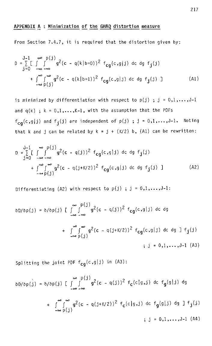
217
APPENDIX A : Minimization of the GHAQ distortion measure
From Section 7.4.7, it is required that the distortion given by:
D =j [ J / 92(c - q(k|b=0))2 fcg(c,g|j) dc dg fj(j) j =0 -<xs -«©
+ J°° T 92(c - q(k|b=l))2 fcg(c,g|j) dc dg fj(j) ] (Al) -^p(j)
is minimized by differentiation with respect to p(j) ; j = 0,1,...,J-l
and q(k) ; k = 0,1,...,K-1, with the assumption that the PDFs
fcg(c,g|j) and f,-(j) are independent of p(j) ; j = 0,1,...,J-l. Noting
that k and j can be related by k = j + (K/2) b, (Al) can be rewritten:
D = l C f^!? ° 92(c - <>(J))2 fcg(c'9lJ) dc d*3 fj(j) j =0 -<*° -~»
+ CT 92<c - q(J+K/2))2 fcg(c,g|j) dc dg fj(j) ] (A2) -~p(j)
Differentiating (A2) with respect to p(j) ; j = 0,1,...,J-l:
0D/dp(j) = 3/dp(j) [ / / 9^(c - q(j)T fcg(c,g|j) dc dg
+ {° f° g2(c - q(j+K/2))2 fcg(c,g|j) dc dg ] fj(j) -^p(j)
; j = 0,1,...,J-1 (A3)
Splitting the joint PDF fcg(c,g|j) in (A3):
*=£> p ( j )
5D/5p(j) = 5/&p(j) [ / J 92(c - q(J))Z fc(c|g,j) dc fg(g|j) dg
+ ~ f° g2(c - q(j+K/2))2 fc(c|g,j) dc fg(g|j) dg ] fj(j) -c-p(j)
; j = 0,1,...,J-1 (A4)

218
In order to simplify (A4), use is made of Leibniz's Rule for the
differentiation of an integral containing a parameter [Wilson 11],
which can be expressed as follows:
If:
b(a) F(a) = / f(x,a) dx
a(a)
Then:
b(a) 5F/da = j df/da dx - f(a,a) da/da + f(b,a) db/da
a(a)
Applying this rule to (A4) gives:
of
oD/dp(j) = [ / g2(p(j) - q(j))2 fc(c|g,j) f (g|j) dg
- J°V(P(J) - q(J+K/2))2 fc(c|g,j) fg(g|j) dg ] fj(j)
; j = 0,1,...,J-1 (A5)
And hence:
5D/dp(j) = [ (p(j) - q(J+K/2))2 - (p(j) - q(j))2 ]
. [ ^c(c|g,j) fg2 fg(g|j) dg ] fj(j) ; j = 0,1,...,J-l (A6)
-©a
Now (A6) is equated with zero, and since g is constrained to be strict
ly positive,
[ (P(j) - q(J+K/2))2 - (p(j) - q(J))2 ] = 0
Giving:
p(j) = 1/2 [ q(j) + q(J+K/2) ] ; J = 0,1 J-l (A7)

219
which is the first design equation.
In differentiating D with respect to q(k) ; k = 0,1,...,K-1, the cases
k = 0,l,...,K/2-l and k = K/2,K/2+l,...,K-1 are considered separately.
Noting that k < K/2-1 for b = 0 and k > K/2 for b = 1, (Al) can be
rewritten:
J-l oo p(j) D = I [ / / g2(c - q(k))2 fcq(c,g|j) dc dg M j )
j=0 -oo-oo U y J
; k = 0,1,...,K/2-1 (A8a)
J-l OO oo 0
D = IE / / g2(c - q(k))2 fcq(c,g|j) dc dg f^j) j=0 - - P ( J ) 9 J
; k = K/2,K/2+l,...,K-l (A8b)
Now (A8a) and (A8b) are differentiated with respect to q(k):
OO p (j)
5D/dq(k) = / / 5/aq(k) [ g2(c - q(k))2 ] fcg(c,g|j) dc dg f-(j)
; k = 0,l,...,K/2-l (A9a)
5D/dq(k) = f° j°° d/5q(k) [ g2(c - q(k))2 ] fcg(c,g|j) dc dg fj(j) -~ p(j)
; k = K/2,K/2+l,...,K-l (A9b)
(A9a) and (A9b) may be simplified to give:
5D/dq(k) = -2 / / g2(c - q(k))^ fcg(c,g|j) dc dg fj(j)
; k = 0,l,...,K/2-l (AlOa)
5D/dq(k) = -2 j" f° g2(c - q(k))2 fcg(c,g|j) dc dg fj(j) -°°P(J)
; k = K/2,K/2+l,...,K-l (AlOb)

220
Equating (AlOa) and (AlOb) with zero and solving for q(k):
<* P(j) 7 / / 9 c fcq(c'9l^ dc d9 -oo -«*> 3
q(k) = — ; k = 0,l,...,K/2-l (Alia) °o p(j) / / 9 f
Cg(c'9lj) dc d9
-CO -OO
' J, vg2 c fcg(c'9|j) dc dg -«*p(j)
q(k) = ; k = K/2,K/2+l,...,K-l (Allb) ,oO cO
/ / g2 fcq(c'9lj) dc d9 -«>P(j)
Combining (Alia) and (Allb) gives:
E{c g2|k} q(k) = ; k = 0,1,...,K-1 (A12)
E{g2|k}
which is the second design equation.
APPENDIX B : Error dissipation in the robust GHAQ
Referring to Fig. 7.5, the encoder syllabic factor g(n) in the robust
GHAQ is given by:
g(n) = (1-B) [|s(n-l)| + I] + B g(n-l) (Bl)
where : B is the syllabic compandor coefficient
s(n) is the GHAQ output level
I is the syllabic increment
Now since:
s(n) = d(n) g(n) (B2)
where d(n) is the quantizer output level, (B2) can be rewritten:

221
g(n) = (1-P) [|d(n-l)| g(n-l) + I] + B g(n-l)
= g(n-l) [(1-6) |d(n-l)| + B] + I (1-B) (B3)
Now g(n-l) in (B3) can be expanded in a manner similar to that in (Bl),
yielding an expression containing g(n-2), and so on. Continuing this
process leads to a general expression:
i i-1 m g(n) = g(n-i) TT ^(n-h) + k2 [ ") JT kx(n-h) ] + k2 ; i > 1 (B4)
h=l m=l h=l
where : kx(h) = (1-B) |d(h)| + B
k2 = I (1-B)
Rewriting (B4) in terms of j = n-i:
n-j n-j-1 m g(n) = g(j) TT M n - h ) + k2 [ \ TT M n - h ) ] + k2 ; j < n-1 (B5)
h=l m=l h=l
A similar expression can also be written for the decoder syllabic
factor g'(n):
n-j n-j-1 m g'(n) = g'(j) TT M n - h ) + k2 [ I TT kx(n-h) ] + k2 ; j < n-1 (B6)
h=l m=l h=l
where : k:'(h) = (1-B) |d'(h)| + B
k2 is as in (B4)
Now consider the case where a single channel bit error causes the
quantities g(j) and g'(j) to differ, for some j. Using (B5) and (B6),
and assuming that no subsequent channel errors occur, the difference
between g(n) and g'(n) for n = j+l,j+2,... can be written:
n-j g(n) - g'(n) = [g(j) - g'(j)] TT kl(n"h) i J < "-1 (B7)

222
From (B5) it is evident that if g(n) is to remain bounded as n-*-©,
then:
n-j-1 m lim C I TTkl(n-h) ] < c ; j < n-1 (B8) n-**> m=l h=l
where c is an arbitary finite constant. This implies that:
m lim ["IT M n - h ) ] = 0 ; m = n-j-1, j < n-1 (B9) n-**> h=l
Applying (B9) to (B7), it is evident that:
lim [g(n) - g'(n)] = 0 (BIO) n+«o
That is, the difference between the syllabic factors in the encoder and
decoder is dissipated with time. The rate at which this difference is
dissipated depends on the successive values of kj(n-h) in the product
term in (B7), which are in turn dependent on the input signal statis
tics.
APPENDIX C : The minimum output level of the robust GHAQ
The general expression derived in Appendix B for the syllabic factor
g(n) of the robust GHAQ in terms of g(j) is:
n-j n-j-1 m 9(n) = g(j) TT M n - h ) + k2 [ I T T M n - h ) ] + k2 ; j < n-1 (Cl)
h=l m=l h=l
where : k:(h) = (1-8) |d(h)| + B
k2 = I (1-B)
B is the syllabic compandor coefficient

223
d(h) is the quantizer output level
I is the syllabic increment
Consider the case where |d(n)| assumes its minimum value, dm1n, for
some n = j , and maintains it for all subsequent n = j+l,j+2,... The
corresponding value of kj(h) is denoted by kx (ie. a constant). Now
(Cl) may be rewritten:
n-j n-j-1 m lim [g(n)] = g(j) lim [ T J k ^ + k2 lim [ | TT kl + 1 ] ; J < n-1 (C2) n-** n+*> h=l n-*» m=i n=l
But since dmin must be less than unity if g(n) is to remain bounded,
(C2) may be reduced to:
n-j-1 m lim [g(n)] = k2 1 im [ £ XT kl + l- > J < n"l (C3) n-»"« n-**> m=l h=l
Since k̂ is a constant, the right-hand term in (C3) contains an
infinite geometric series, so that (C3) may be reduced to:
lim [g(n)] = k2 / (1 - k:) n->oo
= I / (1 - dmin) (C4)
This expression shows that the minimum value of the syllabic factor in
the robust GHAQ is dependent on the syllabic increment and the minimum
quantizer reconstruction level. The minimum GHAQ output level, smi-n,
will thus be the product of the syllabic factor and the minimum quanti
zer reconstruction level:
s . = l dmin (C5)
d - dminJ
It should be noted that infinite-precision arithmetic is assumed in the

224
above analysis. In practice, truncation error will cause g(n) to be
slightly less than the value calculated in (Cl) to (C4), with the
result that (C5) provides an upper bound on sm i n in a limited-precision
implementation of the robust GHAQ.
APPENDIX D : Development equipment and software
The coding algorithm described in this thesis was developed using
software written in Pascal and Basic, running on a Hewlett-Packard
9836C computer. The capabilities of this software included the acqui
sition, storage, and playback of digitized speech, as well as the
implementation of PCM, ADPCM and ADM coding algorithms and the calcula
tion of the SNR and SNRSEG performance measures. Other capabilities
included the design and implementation of digital filters for interpo
lation and decimation of sample sequences, quantizer optimization using
the Lloyd-Max algorithm, optimization of the GHAQ using the procedure
derived in Section 7.4.7, and predictor optimization using the Flexible
Polyhedron Method. The associated hardware comprised 12-bit A/D and
D/A convertors, standard PCM pre-sampling and reconstruction filters, a
high-quality electret condenser microphone, and a standard electromag
netic telephone handset.
The assembly language program implementing the coding algorithm on the
TMS320E17 digital signal processor was developed using a Texas Instru
ments simulation program running on an IBM PC. Input and output sample
sequences were transferred to and from a 12-bit data acquisition/play
back card, with the same filters as described above and an electromag
netic telephone handset.
The codec card was tested and evaluated using software written in the C
language, running on an IBM PC. Capabilities of this software included

225
the examination and modification of the card control/status register
and of any byte in the card memory, and the corruption of code bits on
a random basis, thereby simulating channel errors. In addition, code
could be stored on and retrieved from disk, and converted to and from
64 kbps PCM form, thereby allowing the calculation of signal-to-noise
ratio figures for the complete PCM-EC-PCM coding operation, as de
scribed in Section 9.1.
APPENDIX E : Reference speech material
The following sentences from the "Harvard" list [IEEE 69] of phonetic
ally balanced sentences were used as test inputs. The sex and identity
of the speaker is indicated in brackets in each case.
(1) The birch canoe slid on the smooth planks. (Male 1)
(2) Glue the sheet to the dark blue background. (Male 1)
(3) It's easy to tell the depth of a well. (Female 1)
(4) These days a chicken leg is rare dish. (Female 1)
(5) The boy was there when the sun rose. (Male 2)
(6) A rod is used to catch pink salmon. (Male 2)
(7) The source of the huge river is the clear spring. (Female 2)
(8) Kick the ball straight and follow through. (Female 2)
APPENDIX £ : Adaptive quantizers used in the comparative tests
The adaptive quantizers used in the comparative tests of Section 7.6,
namely the CFDMAQ, the HCDMAQ, and the JAQ, are described here in terms
of the predictive coder of Fig. 7.1. Each adaptive quantizer may
be thought of as consisting of a fixed quantizer and some form of
variance estimator. The input sample v(n) is compressed using a seal-

226
ing factor or "step size" A(n) obtained from the variance estimator,
quantized using a fixed quantizer, and then expanded again to give
s(n). This process may be expressed:
s(n) = QM(c(n)) A(n) (FI)
c(n) = v(n) / A(n) (F2)
where Qj^(c(n)) denotes fixed (ie. time-invariant) M-bit quantization of
c(n). The distinguishing features of the CFDMAQ, the HCDMAQ and the
JAQ are as fol lows:
CFDMAQ:
In the CFDMAQ, a 1-bit fixed quantizer is used, with a single decision
level equal to zero, and reconstruction levels with nominal values of
+1 and -1. The quantizer scaling factor A(n) is calculated recursively
as shown in (F4) below. The CFDMAQ may be described by:
s(n) = Q2(c(n)) A(n) (F3)
A(n) = m(n) A(n-l) (F4)
fl.5 ; b0(n) = b0(n-l) m(n) = < (F5J
10.67 ; b0(n) t bQ(n-l)
HCDMAQ:
The fixed quantizer in the HCDMAQ is the same as that in the CFDMAQ.
However, in the HCDMAQ A(n) is proportional to the product of an "in
stantaneous" factor y(n) and a "syllabic" factor g(n). The instantan
eous factor is calculated recursively as shown in (F8) below. In the
original form of the HCDMAQ [Un 81], the syllabic factor is calculated
as the RMS slope energy of the signal estimate y(n), using a periodi
cally updated block average.

227
However, the results presented in Section 7.6.3 correspond to the use
of a recursive average magnitude estimator (shown in (F9) below) to
calculate the syllabic factor, as the recursive estimator is much
easier to implement in digital hardware than the original scheme, and
little difference (<1 dB) was found between the performances of the two
versions of the HCDMAQ when coding speech. The version used here may
be described by:
s(n) = Q^cfn)) A(n) (F6)
A(n) = ag(n) Y(n) (F7)
Y(n) = m(n) y(n-l) (F8)
g(n) = (1-B) A(n-l) + 8 g(n-l) (F9)
where a is a constant and m(n) is selected according to the rule given
in Table FI. The parameter p associated with the time constant of the
average magnitude estimator is set to 0.98, and the constant a to 0.7,
these values having been found empirically to maximize the SNR.
JAQ:
In the 2-bit JAQ a 2-bit fixed quantizer is used, with decision and
reconstruction levels matched to the PDF of the compressed input sig
nal. The quantizer scaling factor A(n) is calculated recursively as
shown in (Fll) below. The 2-bit JAQ may be described by:
s(n) = Q2(c(n)) A(n) (F10)
A(n) = m(n) A(n-l) (F11)
where the multiplier m(n) is selected according to the rule given in
Table F2. Since the optimum values of the multipliers depend upon the
long-time-averaged autocorrelation function of the input signal [Jayant
73], different sets are specified for use in PCM and DPCM codecs,

-0M
0
0
0
0
1
1
1
1
i>Q{n-l)
0
0
1
1
0
0
1
1
b0(n-2)
0
1
0
1
0
1
0
1
m(n)
1.5
1.0
0.66
0.66
0.66
0.66
1.0
1.5
Table FI Step size multipliers m(n) for the HCDMAQ [Un 81]
^(n)
0
0
1
1
b0(n)
0
1
0
1
m(n)
PCM
2.20
0.60
0.60
2.20
DPCM
1.60
0.80
0.80
1.60
Table F2 Step size multipliers m(n) for the 2-bit JAQ [Jayant 73]
j
0
1
2
3
4
P(j)
- eO
-1.127
0.000
1.127
C O
q(j)
-1.834
-0.420
0.420
1.834
Table F3 Normalized decision levels p(j) and reconstruction levels
q(j) for a 2-bit non-uniform quantizer optimized for a signal
with a Laplacian PDF [Jayant 84]

229
respectively. In this work a 2-bit nonuniform quantizer optimized for
signals with symmetrical Laplacian PDFs [Jayant 84] was used, and the
associated decision and reconstruction levels (normalized for a signal
variance of unity), are given in Table F3.
230
REFERENCES
G.J. Anido, "The design, analysis and implementation of a fully dis
tributed local area network for integrated voice and data communica
tions", Ph.D. thesis, University of New South Wales, Nov. 1987.
M. Aoki, F. Ishino, F. Ishino, "Speech qual ity of conversational pack-
etized voice communications", Trans. IECE Japan, vol. E 69, pp. 107-
112, Feb. 1986.
G. Barberis and D. Pazzaglia, "Analysis and optimal design of a packet-
voice receiver", IEEE Trans. Commun., vol. 28, pp. 217-227, Feb. 1980.
T.P. Barnwell and S.R. Quackenbush, "An analysis of objectively compu
table measures for speech quality testing", Proc. Int. Conf. Acoust.,
Speech, and Signal Proc, Paris, pp. 996-999, 1982.
P.A. Bello, R.N. Lincoln, H. Gish, "Statistical del ta modul ation",
Proc. IEEE, vol. 55, pp. 308-319, Mar. 1967.
T. Bially, B. Gold, S. Seneff, "A technique for adaptive voice flow
control in integrated packet networks", IEEE Trans. Commun., vol. 28,
pp. 325-333, Mar. 1980.
T. Bially, A.J. McLaughlin, CJ. Weinstein, "Voice communication in
integrated digital voice and data networks", IEEE Trans. Commun., vol.
28, pp. 1478-1489, Sept. 1980.
J. Burgin, "Integrated services packet network - protocol design con
siderations", Telecom Australia Branch Paper 108 (Switching and Signal
ling Branch), Jan. 1987.

231
P. Bylanski and T.W. Chong, "Advances in speech coding for communica
tions", GEC J. of Research, vol. 2, pp. 16-22, 1984.
R. Camrass, "New technologies to make their mark in the corporate
network", Communication Systems Worldwide, pp. 30-40, Oct. 1987.
P. Castellino and C. Scagliola, "Design of instantaneously companded
delta modulators with m-bit memory", Proc. Int. Conf. on Acoustics,
Speech and Signal Proc, Hartford, pp. 196-199, May 1977.
K.W. Cattermole, Principles of Pulse Code Modulation. London : Iliffe,
1969.
CV. Chakravarthy and M.N. Faruqui, "A multidigit adaptive delta modu
lation (ADM) system", IEEE Trans. Commun., vol. 24, pp. 931-935, Aug.
1976.
J.-H. Chen and A. Gersho, "Gain-adaptive vector quantization with
application to speech coding", IEEE Trans. Commun., vol. 35, pp. 918-
930, Sept. 1987.
D. Cohen, "A protocol for packet-switching voice communication", Compu
ter Networks, vol. 2, pp. 320-331, 1978.
R.V. Cox and R.E. Crochiere, "Multiple user variable rate coding for
TASI and packet transmission systems", IEEE Trans. Commun., vol. 28,
pp. 334-344, Mar. 1980.
M. Decina and G. Modena, "CCITT Standards on Digital Speech Process
ing", IEEE. J. Selected Areas Commun., vol 6, pp. 227-234, Feb. 1988.
J.H. Derby and CR. Gal and, "Multirate subband coding applied to digi
tal speech interpolation", IEEE Trans. Acoust., Speech, Signal Proc,
vol. 35, pp. 1684 - 1698, Dec. 1987.
232
J. DeTreville and W.D. Sincoskie, "A distributed experimental communi
cations system", IEEE. J. Selected Areas Commun., vol. 1, pp. 1070-
1075, Dec. 1983.
J.D. DeTreville, "A simulation-based comparison of voice transmission
on CSMA/CD networks and on token buses", Bell Syst. Tech. J., vol. 63,
pp. 33-55, Jan. 1984.
D.E. Dodds, A.M. Sendyk, D.B. Wohlberg, "Error tolerant adaptive algo
rithms for delta-modulation coding", IEEE Trans. Commun., vol. 28, pp.
385-391, Mar. 1980.
P.G. Drago, A.M. Molinari, F.C Vagliani, "Digital dynamic speech
detectors", IEEE Trans. Commun., vol . 26, pp. 140-145, Jan. 1978.
J.J. Dubnowski and R.E. Crochiere, "Variable rate coding of speech",
Bel 1 Syst. Tech. J., vol. 58, pp. 577-600, Mar. 1979.
C. A. Dvorak and J.R. Rosenberger, "Deriving a subjective testing
methodology for digital circuit multiplication and packetized voice
systems", IEEE J. Selected Areas Commun., vol. 6, pp. 235-241, Feb.
1988.
CC Evci, CS. Xydeas, R. Steele, "Sequential adaptive predictors for
ADPCM speech encoders", Nat. Telecomm. Conf., pp. E8.1.1-E8.1.5, Nov.
1981.
T.R. Fischer and P.F. Dahm, "Variance estimation and adaptive quantiza
tion", IEEE Trans. Inf. Theory, vol. 31, pp. 428-433, May 1985.
J.L. Flanagan et al., "Speech coding", IEEE Trans. Commun., vol. 27,
pp. 710-736, Apr. 1979.

233
J.W. Forgie, "Network speech - System implications of packetized
speech", Annual Report to the Defense Communications Agency, Lincoln
Lab., Massachusetts Institute of Technology, 1976.
V.S. Frost, E.M. Friedman, G.J. Minden, "Multirate voice coding for
load control on CSMA/CD local computer networks", 10th Conf. on Local
Computer Networks, Minneapolis, pp. 10-19, Oct. 1985.
CK. Gan and R.W. Donaldson, "Adaptive silence deletion for speech
storage and voice mail applications", IEEE Trans. Acoust., Speech,
Signal Proc, vol. 36, pp. 924-927, June 1988.
M.L. Gayford, Electroacoustics. London : Newnes-Butterworths, 1970.
K.C.E Gee, Introduction to Local Area Networks. London : Macmillan,
1983.
J.D. Gibson, "Sequentially adaptive backward prediction in ADPCM speech
coders", IEEE Trans. Commun., vol. 26, pp. 145-150, Jan. 1978.
J.W. Glasbergen, "This versatile IC digitizes speech", Philips Telecom.
Review, vol. 39, pp. 147-154, Sept. 1981.
B. Gold, "Digital speech networks", Proc IEEE, vol. 65, pp. 1636-1658,
Dec. 1977.
A.J. Goldberg, "Practical implementations of speech waveform coders for
the present day and for the mid 1980s", J. Acoust. Soc Amer., vol . 66,
pp. 1653-1657, Dec. 1979.
T.A. Gonsalves, "Packet-voice communication on an Ethernet local compu
ter network : An experimental study", Technical Report No. 230, Compu
ter Systems Lab., Stanford Univ., Feb. 1982.
D.J. Goodman and R.M. Wilkinson "A Robust Adaptive Quantizer", IEEE
Trans. Commun., vol. 23, pp. 1362-1365, Nov. 1975.
D.J. Goodman, "Embedded DPCM for variable bit rate transmission", IEEE
Trans. Commun., vol. 28, pp. 1040-1046, July 1980.
D.J. Goodman et al., "Waveform substitution techniques for recovering
missing speech segments in packet voice communications", IEEE Trans.
Acoust., Speech, Signal Proc, vol. 34, pp. 1440-1447, Dec. 1986.
J.G. Gruber, "Delay related issues in integrated voice and data net
works", IEEE Trans. Commun., vol . 29, pp. 786-800, June 1981.
J.G. Gruber and N.H. Le, "Performance requirements for integrated
voice/data networks", IEEE J. Selected Areas Commun., vol. 1, pp. 981-
1005, Dec. 1983.
J.G. Gruber and L. Strawczynski, "Subjective effects of variable delay
and speech clipping in dynamically managed voice systems", IEEE Trans.
Commun., vol. 33, pp. 801-808, Aug. 1985.
S.C. Hall and H.S. Bradlow, "The design of a hybrid adaptive quantizer
for speech coding applications", to be published in IEEE Trans.
Commun., Nov. 1988.
D.M. Himmelblau, Applied Nonlinear Programming. New York : McGraw-
Hill, 1972.
IEEE Subcommittee on Subjective Measurements, "IEEE recommended prac
tice for speech quality measurements", IEEE Trans, on Audio and Elec
troacoustics, vol. 17, pp. 227-246, Sept. 1969.
Intel Corporation, Telecommunications Products Handbook. 1984.

235
J.M. Irvine, S.C. Hall, H.S. Bradlow, "An improved hybrid companding
delta modulator", IEEE Trans. Commun., vol. 34, pp. 995-998, Oct. 1986.
N.S. Jayant, "Adaptive delta modulation with a one-bit memory", Bell
Syst. Tech. J., vol. 49, 321-342, Mar. 1970.
N.S. Jayant, "Adaptive quantization with a one-word memory", Bell Syst.
Tech. J., pp. 1119-1144, Sept. 1973.
N.S. Jayant, "Step-size transmitting differential coders for mobile
telephony", Bel 1 Syst. Tech. J., vol. 54, pp. 1557-1580, Nov. 1975.
N.S. Jayant, "On the delta modulation of a first-order Gauss-Markov
signal ", IEEE Trans. Commun., vol. 26, pp. 150-156, Jan. 1978.
N.S. Jayant and S.W. Christensen, "Effects of packet losses in waveform
coded speech and improvements due to an odd-even sample-interpolation
procedure", IEEE Trans. Commun, vol. 29, pp. 101-109, Feb. 1981.
N.S. Jayant, "Variable rate ADPCM based on explicit noise coding", Bell
Syst. Tech J., vol. 62, pp. 657 - 677, Mar. 1983.
N.S. Jayant and P. Noll, Digital Coding of Waveforms. New Jersey :
Prentice-Hall , 1984.
D.H. Johnson and G.C. O'Leary, "A local access network for packetized
digital voice communication", IEEE Trans. Commun., vol. 29, pp. 679-
688, May 1981.
R.E. Kahn, "Advances in packet radio technology", Proc. IEEE, vol. 66,
pp. 1468-1496, Nov. 1978.

236
N. Kitawaki et al., "Comparison of objective speech quality measures
for voiceband codecs", Proc. Int. Conf. Acoust., Speech, Signal Proc,
Paris, pp. 1000-1003, 1982.
J.F. Kurose, M. Schwartz, Y. Yemini, "Multiple-access protocols and
time-constrained communication", Computing Surveys, vol. 16, pp. 43-70,
Mar. 1984.
G.G. Langenbucher, "Efficient coding and speech interpolation : Prin
ciples and performance characterization", IEEE Trans. Commun., vol. 30,
pp. 769-779, Apr. 1982.
Y. Linde, A. Buzo, R.M. Gray, "An algorithm for vector quantizer
design", IEEE Trans. Commun., vol. 28, pp. 84-95, Jan. 1980.
S.P. Lloyd, "Least squares quantization in PCM", unpublished memo.,
Bell Lab., 1957; IEEE Trans. Information Theory, vol. 28, pp. 129-137,
Mar. 1982.
D.T. Magill and CK. Un, "Speech residual coding by adaptive delta
modulation with hybrid companding", Proc. Nat. Electronics Conf., vol.
29, pp. 403-408, 1977.
X. Maitre and T. Aoyama, "Speech coding activities within CCITT :
Status and trends", Proc. Int. Conf. Acoust., Speech, Signal Proc,
Paris, pp. 954-959, 1982.
M. Malek, "Integrated voice and data communications overview", IEEE
Commun. Mag., vol . 26, pp. 5-15, June 1988.
J. Max, "Quantizing for minimum distortion", IRE Trans. Inf. Theory,
vol. 6, pp. 7-12, Mar. 1960.

237
B. McDermott, C Scagliola, D. Goodman, "Perceptual and objective
evaluation of speech processed by adaptive differential PCM", Bell
Syst. Tech. J., vol. 57, pp. 1597 - 1619, May 1978.
P. Mermelstein, "G.722, A new CCITT coding standard for digital trans
mission of wideband audio signals", IEEE Commun. Mag., vol. 26, pp. 8-
15, Jan. 1988.
D. Mi noli, "Optimal packet length for packet voice communication", IEEE
Trans. Commun., vol. 27, pp. 607-611, Mar. 1979.
W.A. Montgomery, "Techniques for packet voice synchronization", IEEE J.
Selected Areas Commun., vol. 1, pp. 1022-1028, Dec. 1983.
M. Nakatsui and P. Mermelstein, "Subjective speech-to-noise ratio as a
measure of speech quality for digital waveform coders", J. Acoust. Soc.
Amer. vol. 72, pp. 1136 - 1144, Oct. 82.
M.E.M. Nasr and CV. Chakravarthy, "Hybrid adaptive quantization for
speech coding", IEEE Trans. Commun., vol. 32, pp. 1358-1361, Dec. 1984.
J.E. Natvig, "Evaluation of six medium bit-rate coders for the Pan-
European digital mobile radio system", IEEE J. Selected Areas Commun.,
vol. 6, pp. 324-331, Feb. 1988.
J.A. Nelder and R. Mead, "A simplex method for function minimization",
Computer Journal, vol. 7, pp. 308-313, 1965.
T. Nishitani et al., "A CCITT standard 32 kbit/s ADPCM LSI codec", IEEE
Trans. Acoust., Speech, Signal Proc, vol. 35, pp. 219-225, Feb. 1987.
P. Noll, "A comparative study of various quantization schemes for
speech coding", Bel 1 Syst. Tech. J., vol. 54, pp. 1597-1614, Nov. 75.
238
G.C. O'Leary et al., "A modular approach to packet voice terminal
design", Nat. Computer Conf., pp. 183-189, 1981.
S.N. Pandhi, "The universal data connection", IEEE Spectrum, vol. 24,
pp. 31-37, July 1987.
L.R. Rabiner and R.W. Schafer, Digital Processing of Speech Signals.
New Jersey : Prentice-Hall, 1978.
F.T. Sakane and R. Steele, "Two-bit instantaneously adaptive delta
modulation for p.c.m. encoding", The Radio and Electronic Engineer,
vol. 48, pp. 187-197, Apr. 1978.
C. Scagliola, "Evaluation of adaptive speech coders under noisy channel
conditions", Bell Syst. Tech. J., vol 58, pp. 1369 - 1394, July 1979.
M. Schwartz and L. Shaw, Signal Processing : Discrete Spectral
Analysis, Detection and Estimation. New York : Mcgraw-Hill, 1975.
R. Seidl, "Echo and delay in packet voice services", 2nd Fast Packet
Switching Workshop, Melbourne, May 1987.
A. Seneviratne, "Factors influencing the quality of packet voice", 2nd
Fast Packet Switching Workshop, Melbourne, May 1987.
T. Suda, H. Miyahara, T. Hasegawa, "Performance evaluation of a packet-
ized voice system - simulation study", IEEE Trans. Commun., vol. 32,
pp. 97-102, Jan. 1984.
A.S. Tanenbaum, Computer Networks. New Jersey : Prentice-Hall, 1981.
H. Taub and D.L. Schilling, Principles of Communication Systems. New
York : McGraw-Hil 1, 1971.
Texas Instruments Inc., TMS32010 User's Guide. 1985.

239
J. Tierney and M.L. Mai pass, "Enhanced CVSD - an embedded speech coder
for 64-16 kbps", Proc. IEEE Int. Conf. on Acoustics, Atlanta, pp. 840-
843, Mar. 1981.
K.-H. Tzou, "Embedded Max quantization", Int. Conf. Acoust., Speech,
Signal Proc, Tokyo, pp. 10B.3.1-10B.3.4, 1986.
CK. Un and H.S. Lee, "A study of the comparative performance of adapt
ive delta modulation systems", IEEE Trans. Commun., vol. 28, pp. 96-
101, Jan. 1980.
CK. Un and H.H. Lee, "Voiced/unvoiced/silence discrimination of speech
by delta modulation", IEEE Trans. Acoust., Speech and Signal Proc, vol
28, pp. 398-407, Aug. 1980.
CK. Un, H.S. Lee, J.S. Song, "Hybrid companding delta modulation",
IEEE Trans. Commun., vol. 29, pp. 1337-1344, Sept. 1981.
CK. Un and D.H. Cho, "Hybrid companding delta modulation with
variable-rate sampling", IEEE Trans. Commun., vol. 30, pp. 593-599,
Apr. 1982.
R. Vickers and T. Vilmansen, "The evolution of telecommunications
technology", IEEE Commun. Mag., vol. 25, pp. 6-18, July 1987.
O.J. Wasem et al., "The effect of waveform substitution on the quality
of PCM packet communications", IEEE Trans. Acoust., Speech, Signal
Proc, vol. 36, pp. 342-348, Mar. 1988.
S.A. Webber, CJ. Harris, J.L. Flanagan, "Use of variable-quality
coding and time-interval modification in packet transmission of
speech", Bel 1 Syst. Tech. J., vol . 56, pp. 1569-1573, Oct. 1977.
CJ. Weinstein and E.M. Hofstetter, "The tradeoff between delay and
TASI advantage in a packetized speech multiplexer", IEEE Trans.
Commun., vol 27, pp. 1716-1720, Nov. 1979.
CJ. Weinstein and J.W. Forgie, "Experience with speech communication
in packet networks", IEEE J. Selected Areas Commun., vol. 1, pp. 963-
980, Dec. 1983.
S.B. Weinstein, "Telecommunications in the coming decades", IEEE Spec
trum, pp. 62-67, Nov. 1987.
L. Weiss, I.M. Paz, D.L. Schilling, "Video encoding using an adaptive
digital delta modulator with overshoot suppression", IEEE Trans.
Commun., vol. COM-23, pp. 905-920, Sept. 1975.
E.B. Wilson, Advanced Calculus. Boston : Athenaeum Press, 1911.
P. Yatrou and P. Mermelstein, "Ensuring predictor tracking in ADPCM
speech coders under noisy transmission conditions", IEEE J. Selected
Areas Commun., vol. 6, pp. 249-261, Feb. 1988.
Y. Yatsuzuka, "High-gain digital speech interpolation with adaptive
differential PCM encoding", IEEE Trans. Commun., vol. 30, pp. 750-761,
Apr. 1982.
ABBREVIATIONS AND ACRONYMS
ACF - Autocorrelation Function
ADM - Adaptive Delta Modulation
ADPCM - Adaptive Differential Pulse Code Modulation
APCM - Adaptive Pulse Code Modulation
bps - bits per second i
CCITT- International Telegraph and Telephone Consul tative Committee
CFDMAQ - Constant Factor Delta Modulation Adaptive Quantizer
CVSD - Continuously Variable Slope Delta modulation
DM - Delta Modulation
DMA - Direct Memory Access
DPCM - Differential Pulse Code Modulation
DCM - Digital Circuit Multiplication
DSI - Digital Speech Interpolation
DSP - Digital Signal Processor
EC - Embedded Coding
FIFO - First-In First-Out
FPS - Fast Packet Switching
GHAQ - Generalized Hybrid Adaptive Quantizer
HCDMAQ - Hybrid Companding Delta Modulation Adaptive Quantizer
ISDN - Integrated Services Digital Network
JAQ - Jayant Adaptive Quantizer
k = 1000 (eg..kHz)
K = 1024 (eg. Kbytes)
LAN - .Local Area Network
M = IO6 (eg. Mbps)
PABX - Private Automatic Branch Exchange
PCM - Pulse Code Modulation

PDF - Probability Density Function
PSTN - Public Switched Telephone Network
SAD - Speech Activity Detection
SBC - Sub-Band Coding
SDM - Statistical Delta Modulation
SNR - Signal-to-Noise Ratio
SNRF - Signal-to-Noise Ratio after Filtering
SNRSEG - Segmental Signal-to-Noise Ratio
SNRSEGF - Segmental Signal-to-Noise Ratio after Filtering
TASI - Time Assignment Speech Interpolation
WAN - Wide Area Network