1983/42. slope stability and subsurface investigation of a ...€¦ · slope stability and...
TRANSCRIPT
1983/42. Slope stability and subsurface investigation of a subdivision at Deviot.
W.R. Moore
Abstract
A large block at Deviot is to be subdivided into four building lots on which three new houses are to be built. The block comprises a high terrace, an old dissected scarp, and a long uniform slope down to the River Tamar. Slope failure appears to have occurred on the scarp, producing a series of benches at the foot of the slope. The scarp and these benches are zoned as potential landslide areas.
Two houses are to be sited on these benches, and the third house is to be built at the head of the long slope. Three trenches were dug on these sites. Underlying surface gravel and sandy soil layers on the benches is highly plastic fissured clay with high linear shrinkages. Even though slope failure appears unlikely at these two sites, potential foundation movements, because of the expansive clay, are considered a problem. At the third site the underlying clay is sandy with a low linear shrinkage, and the potential movement is considered likely to be small.
An alternative house site is recommended at one site. On the second site a strengthened raft foundation for the house is recommended. This should be designed by a structural engineer and considerable care should be taken with the drainage of the site. On the third site a raft foundation capable of taking limited movement is recommended for the house.
INTRODUCTION
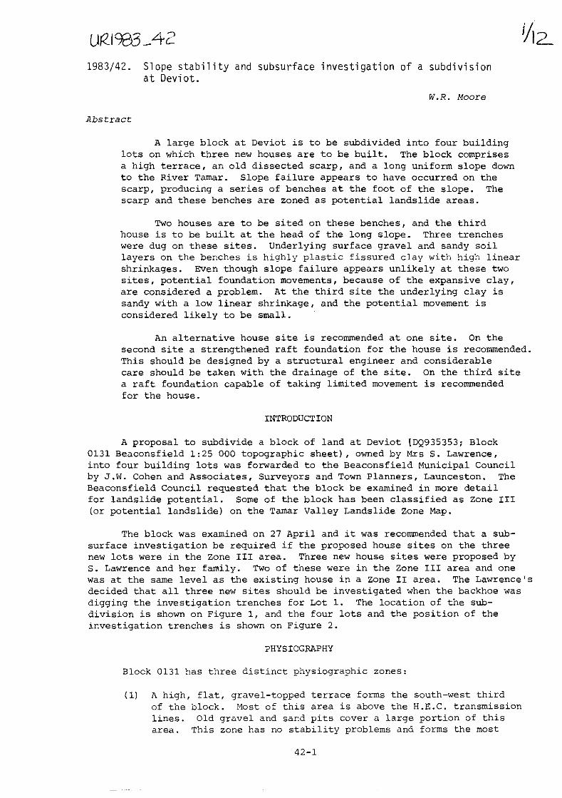
A proposal to subdivide a block of land at Deviot [DQ935353; Block 0131 Beaconsfield 1:25 000 topographic sheet), owned by Mrs S. Lawrence, into four building lots was forwarded to the Beaconsfield Municipal Council by J.W. Cohen and Associates, Surveyors and Town Planners, Launceston. The Beaconsfield Council requested that the block be examined in more detail for landslide potential. Some of the block has been classified as Zone III (or potential landslide) on the Tamar Valley Landslide Zone Map.
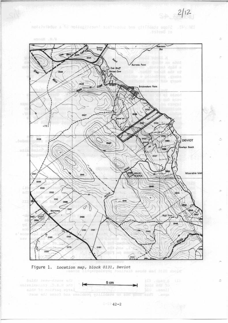
The block was examined on 27 April and it was recommended that a subsurface investigation be required if the proposed house sites on the three new lots were in the Zone III area. Three new house sites were proposed by S. Lawrence and her family. Two of these were in the Zone III area and one was at the same level as the existing house in a Zone II area. The Lawrence's decided that all three new sites should be investigated when the backhoe was digging the investigation trenches for Lot 1. The location of the subdivision is shown on Figure 1, and the four lots and the position of the investigation trenches is shown on Figure 2.
PHYSIOGRAPHY
Block 0131 has three distinct physiographic zones:
(1) A high, flat, gravel-topped terrace forms the south-west third of the block. Most of this area is above the H.E.C. transmission lines. Old gravel and sand pits cover a large portion of this area. This zone has no stability problems and forms the most
42-1
&art.as PoInt
\
"".
'---
"''' Figure 1. Location map, block 0131, Deviot
Scm
42-2
-"'" y
Miserable Isle
,;.
-
..
® "
• o. TRENd)H 2
• --"'" -- LINES ----•
.., CD Block number 7 _'4\'10 JI
7 _'4\'10 Trench on proposed - house position r<l Existing buildings
Scm
Figure 2. Plan of proposed subdivision with trench sites marked.
42-3

stable part of the subdivision, and is classified as a Zone II area. Because access can only be obtained from the Deviot Road this area would be too costly to site houses.
(2) From the high terrace, the block falls steeply by a bush covered dissected scarp from a height of 90 m to a height of 50 m, with slopes of 12-15°. Below the 50 m level, a break in slope occurs, with some irregular benching present. These benches may be the toes of old landslides that have moved down from the scarp. If so, the landslides would be very old and dissected, and it is difficult to be certain of their origin. It is on these irregular benches that the proposed houses on Lots 2 and 3 are to be built.
House Site 1 (for D. Lay) is on the top of the bench, with a slope of 3° from the base of the scarp gradually increasing to 5°. Then with a break of slope, the slope increases to a short 9° slope, which in turns flattens to 6° to merge with the long slope to Deviot Road, the third physiographic zone. House Site 2 (for M. Lawrence) is on a similar bench, but the topography has been modified by the building of a large water hole at the base of the steeper slope. All of this second physiographic zone has been included in Landslide Zone III, an area of potential landslide.
(3) The third physiographic zone is the long uniform slope of 3-5° down to Deviot Road and the River Tamar. It is in the upper section of this slope that the existing Lawrence house, and the proposed new house site (for S. Lawrence) is situated. The long slope gradually steepens towards the road and river. Most of this slope has been zoned as a Zone II landslide area, although slope failures are known to the south and north of Lawrence's subdivision in the slope foot area near the road and river.
GEOLOGY
Except on the upper terrace, where gravel and sand crop out in the old pits, outcrop is poor over the subdivision. A mantle of grey organic sand covers the scarp area. Clay is exposed in the wall of the large waterhole below M. Lawrence's house site. This clay is mottled orange and grey, and appears to have been derived from clay of the Launceston Beds of Tertiary age (Longman, 1966). The block has been mapped on the Beaconsfield 1:63 360 geological map sheet as an area of clay, sand, and gravel of Tertiary age overlain on the high terrace by partially consolidated granule sand of Cainozoic age (Gee and Legge, 1971). Basalt flows of Tertiary age occur north and south of block 0131, but no basalt outcrops were seen during the surface inspection.
SUBSURFACE GEOLOGY (SEE APPENDIX 1)
In Trench 1, a surface layer of gravel with quartz pebbles and partially cemented sand, similar to that occurring in the old sand pits on the high terrace, was exposed. This gravel overlies mottled orange and grey, highly plastic clay.
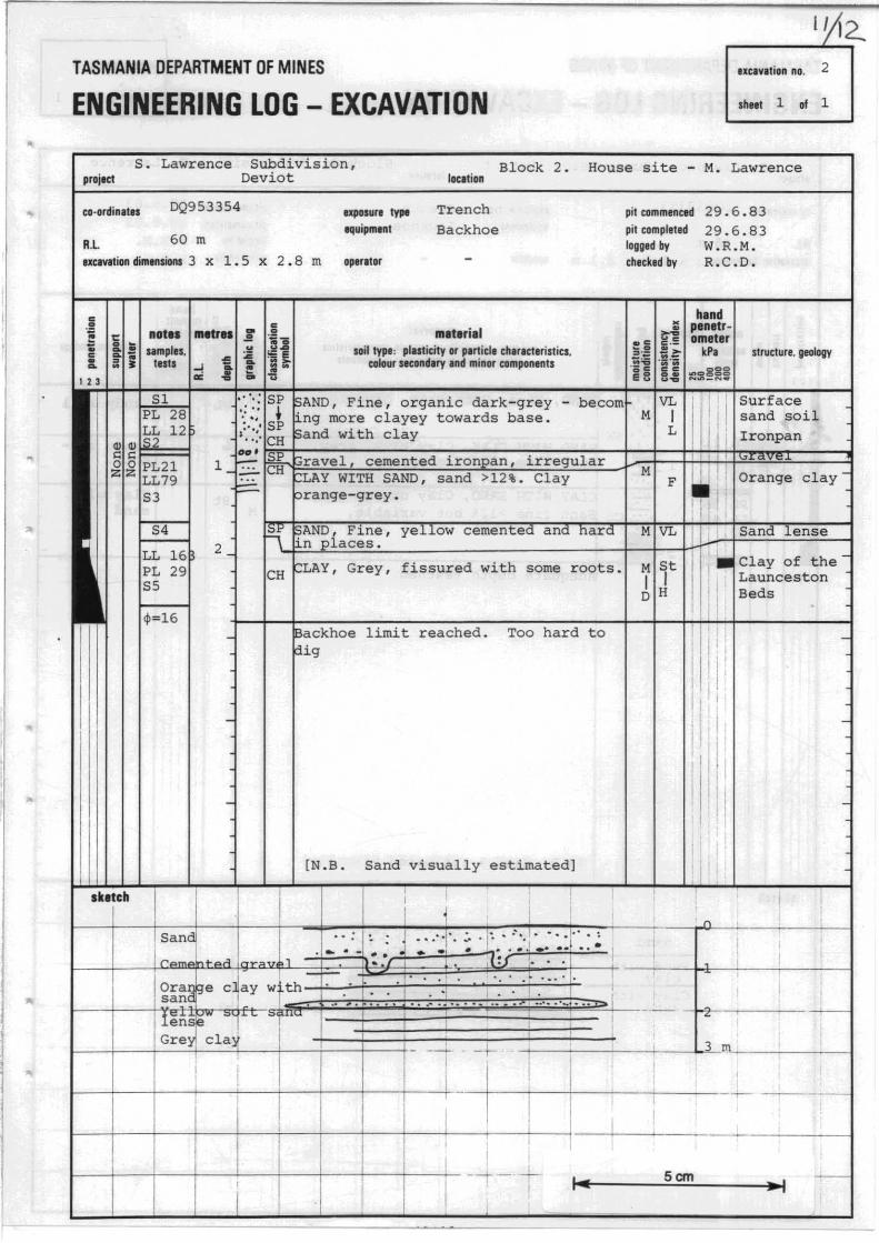
In Trench 2, a dark grey organic surface sand soil, with a clayey sand subsoil and a basal ironstone layer and cemented gravel pockets was exposed. These soil horizons overlie (with a sharp interface) an orangegrey clay with sand. The clay with fine sand grades into a lens of fine
42-4
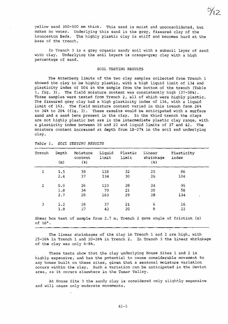
yellow sand 300-500 rnm thick. This sand is moist and unconsolidated, but makes no water. Underlying this sand is the grey, fissured clay of the Launceston Beds. The highly plastic clay is stiff and becomes hard at the base of the trench.
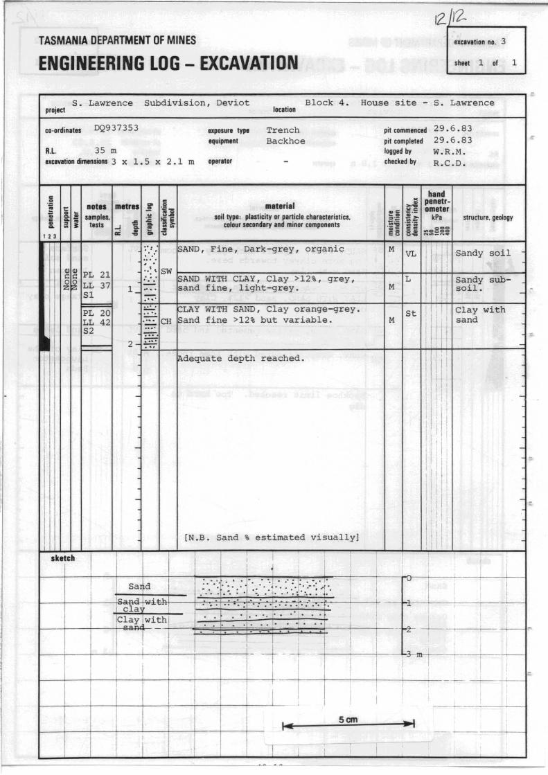
In Trench 3 is a grey organic sandy soil with a subsoil layer of sand with clay. Underlying the soil layers is orange-grey clay with a high percentage of sand.
SOIL TESTING RESULTS
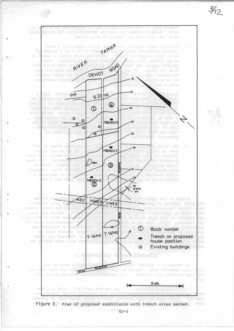
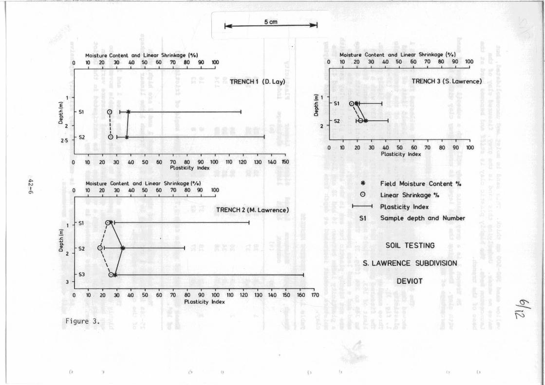
The Atterberg limits of the two clay samples collected from Trench 1 showed the clay to be highly plastic, with a high liquid limit of 134 and plasticity index of 104 in the sample from the bottom of the trench (Table 1, fig. 3). The field moisture content was consistently high (37-38%). Three samples were tested from Trench 2, all of which were highly plastic. The fissured grey clay had a high plasticity index of 134, with a liquid limit of 163. The field moisture content varied in this trench from 26% to 34% to 28% (fig. 3). These results would be anticipated with a surface sand and a sand lens present in the clay. In the third trench the Clays are not highly plastic but are in the intermediate plastic clay range, with a plasticity index between 16 and 22 and liquid limits of 37 and 42. The moisture content increased at depth from 18-27% in the soil and underlying clay.
Table 1. SOIL TESTING RESULTS
Trench Depth Moisture Liquid Plastic Linear Plasticity content limit limit shrinkage index
(m) (%) (%)
1 1.5 38 118 32 25 86 2.4 37 134 30 26 104
2 0.9 26 123 28 24 95 1.8 34 79 21 20 58 2.7 28 163 29 28 134
3 1.2 18 37 21 6 16 1.8 27 42 20 8 22
Shear box test of sample from 2.7 m, Trench 2 gave angle of friction (~)
of 16°.
The linear shrinkages of the clay in Trench 1 and 2 are high, with 25-26% in Trench 1 and 20-28% in Trench 2. In Trench 3 the linear shrinkage of the clay was only 6-8%.
These tests show that the clay underlying House sites 1 and 2 is highly expansive, and has the potential to cause considerable movement to any house built on these sites, given that a seasonal moisture variation occurs within the clay. Such a variation can be anticipated in the Deviot area, as it occurs elsewhere in the Tamar Valley.
At House Site 3 the sandy clay is considered only slightly expansive and will cause only moderate movements.
42-5
I-5cm .. I
Moisture Content and Un.ar Shrinkage (e/e' Moisture Content and Linear Shrinkage (e/e)
0 ~ 20 30 40 50 60 70 80 90 100 0 10 20 30 40 50 60 70 80 90 100 ,
TRENCH 1 (D. Lay) TRENCH 3 (S. Lawrence)
1 ]1
I .c 51 L "K .c 51 i'I 1 .. "K 0 .. 52 0
2 2
2·S 52 01 I
0 10 20 30 40 50 60 70 80 90 100 Plasticity Index
0 10 20 3Q 40 50 60 70 80 90 100 110 120 130 140 150 Plasticity Index
01> Moisture Content and Linear Shrinkage Ie/e) • Field MOisture Content ./. N I 0 10 2? 30 40 50 60 70 80 90 1~ '" 0 Linear Shrinkage ./.
TRENCH 2 (M. Lawrence) 1 1 Plasticity Index
51 . 1 1 SI Sample depth and Number
1
/\ I .c ~ a. 0 SOIL TESTING .. 52 0
2 \
\,.,1 S. LAWRENCE SUBDIVISION
S3 3 DEVIOT
0 10 20 30 40 50 60 70 80 90 100 110 120 130 140 150 160 170 Plasticity Index ~
Figure 3. f::;
(. I .. .. (> \ " II

SLOPE STABILITY
The surface gravel in Trench 1 is lithologically similar to the gravel exposed in the gravel pits on the high terrace. It is difficult
~'2
to visualise the gravel as having been transported down from the high terrace to the foot of the scarp while still preserving the sharp interface between the surface gravel and underlying clay. The benches on which House Sites 1 and 2 are located are possibly toes of old landslides from the scarp, but this cannot be confirmed.
The shear box test on the clay showed a low friction angle of 16°, but this low angle does not necessarily indicate that the clay has already failed. The slopes on the benches are 3-5°, and the benches now appear to be stabilised. If good drainage is installed and storrnwater and septic tank excess water is removed from the benches the risk of slope failure appears slight.
Even though site three is situated on a long slope, the laboratory results support the field evidence that slope failure is not likely to be a problem at this site.
CONCLUSIONS
House Site 1 (D. Lay)
This site is on a bench possibly produced by a landslide, and is underlain by clay which is highly expansive. The surface gravel, although slightly cemented, is unlikely to stop water reaching the clay. Slope failure appears unlikely with suitable drainage of excess water from the house. Considerable soil movement can be anticipated and will remain a problem. The house foundation will need to allow for this movement. Good site drainage will help alleviate the problem.
House site 2 (M. Lawrence)
Both field evidence and soil testing show this is the worst of the three. sites. The underlying clay, both in the subsoil and deeper, is very expansive and fissured. A permeable sandy soil and unconsolidated sand lenses within the clay make it difficult to prevent water reaching the clay. Satisfactory and efficient drainage at the depth at which the unconsolidated sand occurs will be difficult and expensive. As the site is high and close to the scarp, excess water from the sca~p may add to the problems of this site.
House Site 3 (S. Lawrence)
This site appears to provide few problems with slope stability, and the clay with sand below the sandy soil is only slightly expansive.
RECOMMENDATIONS
(1) At House Site 1, a strengthened raft foundation be designed by a structural engineer to meet the anticipated movements of the expansive soil. High priority should also be given to site drainage and drainage maintenance when the house is built. Building should be in accordance with Special Building Regulations for 'B' landslide areas.
42-7

(2) Because of the likely problems associated with House Site 2, an alternative site lower down the slope should be chosen, preferably below the water hole level. Similar trenching and testing should be carried out at the new site.
(3) At House Site 3 it is recommended that a raft type of foundation be used which should be designed to withstand some vertical movement; strict adherence to the Building Regulations is necessary_
GEE, R.D.; LEGGE, P.J. Sheet 30 (8215N).
REFERENCES
1971. Geological atlas one mile series. Zone 7 Beaconsfield. Department of Mines, Tasmania.
LONGMAN, M.J. 1966. One mile geological map series. K/55-7-39. Launceston. Explan.Rep.geol.Surv.Tasm.
[2 September 1983)
42-8
•
..
..
..
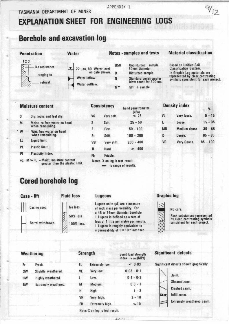
APPENDIX 1 TASMANIA DEPARTMENT OF MINES
EXPLANATION SHEET FOR ENGINEERING LOGS
Borehole and excavation log
Penetration
123
Water Notes -samples and tests
I No reS.istance
ranging to
_ refusal
U50 22 Jan. 80 Water level
on date shown. D
Water inflow.
Water outflow.
N
N*
Undisturbed sample 50mm diameter. Disturbed sample.
Standard penetrometer blow count for 300mm. SPT + sample.
Material classification
Based on Unified Soil Classification System. In Graphic log materials are . represented by clear contrastinQ symbols consIstent for each proJect.
Moisture content Consistency hand penetrometer Density index
" D Dry. looks and feel dry.
M Moist. no free water on hand when remoulding.
' W Wet. free water on hand when remoulding.
II Uquid limit.
Pl Plastic lilnit.
PI Plasticity Index.
ego M > Pl - Moist. moisture content greater then the plastic limit.
Cored borehole log
Case - lift
III Casing used.
H Barrel withdrawn.
Fluid loss
No loss
50% loss
100% loss.
(kPa) VS Very soft. < 25
S Soft. 25 - 50
F Firm. 50 - 100
St Stiff. 100 - 200
VSt Very stiff. 200 - 400
H Hard. > 400
Fb Friable. Notes, X on log is test iosult
- is range of results.
Lugeons
lugeon units (~l) are a measure of rock mass permeability. For a 46 to 74mm diameter borehole 1 lugeon is defined as a rate of loss of 1 litre per metre per minute. 1 lugeon is roughly equivalent to a permeability of 1 X 1 a ., mm / sec.
Weathering Strength point load strength
Fr
SW
HW
EW
Fresh.
Slightly weathered.
Highly weathered.
Extremely weathered.
index "os. (MPa)
El Extremely low. < 0·03
Vl Very low. 0·03-0 '1
l low. 0'1 - 0·3
M Medium. 0·3 - 1
H High 1 - 3
VH Very high. 3 - 10
EH Extremely high. > 10
Note, X on log is test result.
42-9
Vl Very loose. 0-15
l loose. 15 - 35
MD Medium dense. 35 - 65
D Den.e. 65 - 85
VD Vory Dense 85 - 100
Graphic log
No core.
Rock substances represented by clear. contrasting symbols consistent for each project.
Significant defects
Significant defects shown graphically.
Joint.
Sheared zone.
. Crushed seam.
Infill seam.
Extremely weathered seam.
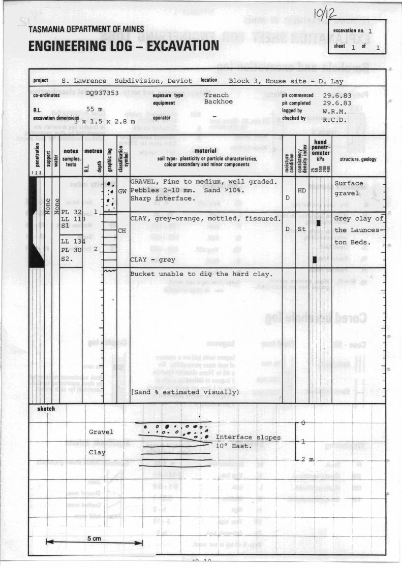
IO/I;:::::..~ __ ---. TASMANIA DEPARTMENT OF MINES txCIVllian no. 1
ENGINEERING LOG - EXCAVATION shOlt 1 of 1
~----------------------------------------------------------~ -proj.ct S. Lawrence Subdivision, Deviot IOCitian Block 3
co-ordinates DQ937353
R.L 55 m IXClVltion dimtn~ x 1.5 x 2.8 m
uposur. type Trench equipment Backhoe
op.r.to, -
mlterill soil type: pllSlicily or particle characteristics.
colour sicond.ry and minor components
House site - D. Lay
pit commenced 29.6.83 pit completed 29.6.83 logged by W.R.M. checked by R.C.D.
hind . .!1 plnttrf~ ometer
i~ ~::~g Li N~_N~ structure, geology
., ~KAV~L , Fine to medium, well graded . GW IPebbles 2-10 mm. Sand >10%.
I
I Surface gravel :. HD , . -, interface. D
..
i ~~~------------------------~-4~~~--------~ -~., " ~ 1
. '. = - ~L~ , grey-orange, mottled , fissured. I I Grey clay 0
St ' II
I
sketch
LL 13 PL 3C
52.
-
-
-
D
~LAY - grey
'" unable to dig the hard clay .
Ir".n" % estimated visually)
, I , I
I ! ,
. r. fI ~~ '0
o. 1 ; ~ , . . I." :. ,. •
"
10° Efst. I ~.~~ __ + __ cla:~_ll __ t==t=:t=JI~LII ~ __ +II __ Li __ 1~
i I i ' I--.!--+--+---+--+---i--+--!f- --l- - -+
I I . ,
I I , I
I , ! i
- +- . Scm ---r- I I- - I I I
I :
, . .., '0
the T"un~o~.
I II I~ 'I!
ton Beds.
; ,
I ;
I I , ,
I ,
I I .J ,
,
· -
·
·
"
[/ 12.. TASMANIA DEPARTMENT OF MINES IXClvltion no. 2
ENGINEERING LOG - EXCAVATION .hHt 1 .f 1
S. Lawrence Subdivision, Dev10t
Block 2. House site - M. Lawrence project
ca -ordinates DQ953354
R.L 60 m
IXClvltion dimensions 3 x 1.5
:s .~ I .. t.. metr.. :l i I! umpill. ~ ~ Ii tl.t, ~ -e I-'" "" .f lo
x 2.8 m
loc.tion
... ur. ~ Trench equipment Backhoe
op.r.tor -
lft.t.,i.1 soil typ. : plasticity or p.rticl. chlred.rislies.
colour sHOndery .nd minor componlnts
Sl IPL 28
~ I~ I~~ 12
I.":; Sf ~AND, Fine, o rganic dark-grey -I'{.··. SP ~ng more clayey towards base. I':::: CH ~and with clay
1 ~.sI'r" " ; I,
-~ CH FLAY WITH SAND, sand >12 % Clay , -,'
I~t~! S3
S4 and nara
I~~ ~~ S5
CH ~LA~ , Grey, fissured with some roots ..
pit commenced pit completed I.gged by chocked by
VL ' M I
L
, ,
29.6.83 29.6.83 W.R.M. R.C.D.
structure. geology
Surface II sand soil I Ironpan
'M F •• :; Orange clay-
! i I
M IVL i I Sana
l:' St I I D H
, I • Clay of the
I Launceston Beds
</> =1 6 _j-~--1s.~~~ll~i~m~itt-r~e;'a~c~h~e~d~.--TT;o;o-h~a~r~djjt~o~t--t--tr~~------------j . ~ig
, II'
-
II i I : I II [I I ' , I I
-
-
i: :1 I, , II I
: I' I I -
I " [N.B . Sand visually estimated] I'
.htch ,
I ' n
: ,
i I ,
I Sane ,
: I , , . .' .1' '. o .. o. I . • 0
": ; .! I .. ." ' ," .. I. ,(:f : .... -.
" I
, ,
•
, ... ' I , .. .; • 1 ,
! ; ' 1 I
-t-I ~~~~~e c lay wi i"h
, , . 3 m
.-.
, + I --I
I I
I I : I i , 1
i ! I I , --'-T I-
I
Scm -
TASMANIA DEPARTMENT OF MINES uelYltion no. 3
ENGINEERING LOG - EXCAVATION .hMt 1 of 1
~--------------------------------------------------------, = s. Lawrence project
" .• rdin.t.. DQ9 3 7 3 5 3
R.L 35 m
Subdivision, Deviot
exposure fyJtt
equipment
lotltion
Trench Backhoe
Block 4.
IXCIV.tion dimensions 3 xl. 5 x 2. 1 m op.r.tor
not., .,. t"t.
, 23
lI.t"i.1 soil typ.: plasticity or p.rlicl. char.cteristics.
colour stcand.ry Ind minor components
:',:... SAND, Fine, Dark-grey, organic
House site - S. Lawrence
pit commenced pit completed logged by checked by
29. 6 .83 29. 6 .83 W.R.M. R . C.D.
M
h.nd . .ll penllr· fi omlt.r
il kP,
.... cggg ....... _ .........
VL
structure. geology
! Sandy soil
:" ~', SW I-:-:-=-~=,....-::-=-:-:::---::-::-.....,:-::-::-----+-If,,-++-+++-'H-------I ~" SAND WITH CLAY, Clay >12 \ , grey, L Sandy sub-
•
,ketch
1 __ ., sand fine, light-grey. M soil. .". " , I ? CLAY WITH SAND, Clay orange-grey . . :.::-:- CH Sand fine >12% but variable. '-;:;,
2- ~ ~, 'r~ depth reached.
-
-
-
[N.B. Sand % estimated visually]
,
: .. , ". ... '. ' :.' .
: . '.' : I" •. :.. • ' .. .. ,..... I.,:·'" . Sand
St M
I Clay with I sand
~
I I ,
1 1 11; ,
I ! , 'I
i' , I I' I
I ! f I
I
,
, .
I
cla ' ,
-
-
-
-
I
•
IC~~X."withi-_~·;2~~·~·~·~f.-~' .~';.'~ .. ~".:; .. ~-t--i-- .. ~ -------'!'----l~ ! I I '
~--1_---+--~r_--+_--_t--~----t_--_t- - - . ~ ~
i --+---t-~-L-~-----~
I I ; I _--_--II·
Scm --~----I
r I