19824 prizm tech man 4/02 4web - med one group...cadd-prizm® vip (variable infusion profile) pump...
TRANSCRIPT

33
TE
CH
NI C
AL
MA N U A L
C A D D- P
riz
m®
A MBULATORYIN
FUS I
ON
PU
MP
M O D E L 6 1 0 1
Deltec
M O D E L 6 1 0 0
This online version differsfrom the printed version.
Certain information that isnot intended for patients
has been removed.

32
For detailed instructions, specifications, warnings, warranties and additional information on operat-ing CADD® pumps, please refer to the Operator’s Manual supplied with the product. If you haveadditional comments or questions concerning the operation of CADD® pumps, please call this num-ber: (800) 426-2448. Our staff is available to help you 24 hours a day with the programming andoperation of CADD® pump infusion systems.
The issue date of this Technical Manual is included for the user’s information. In the event one yearhas elapsed between the issue date and product use, the user should contact Deltec, Inc. to see if alater revision of this manual is available.
Issue Date: April 2002

34
Table of Contents
1. Introduction ............................................. 1Limited Warranty ........................................... 1Exposure to Radiation or Magnetic ResonanceImaging (MRI) ............................................... 1
2. CADD-Prizm® Pump................................ 2Delivery Modes .............................................. 2Specifications (Nominal) ................................ 5
3. Batteries ................................................... 8Battery Compatibility ..................................... 8DURACELL® Alkaline Battery Life ................ 8ULTRALIFE® Lithium Battery Life ................ 8
4. Construction .......................................... 11
5. Theory of Operation .............................. 12Keyboard Circuitry ...................................... 12Data Memory EEPROM .............................. 12Battery Backed RAM ................................... 12Time Base Circuitry ...................................... 12LCD Circuitry .............................................. 12LED Status Indicators .................................. 13Flash PROM Technology ............................. 13Gate Array Circuitry .................................... 13Audible Alarm Circuitry ............................... 13Watchdog Timer Circuit .............................. 13Motor Driver/Motor Watchdog Circuit ....... 13Power Circuitry ............................................ 14Voltage Reference Circuit ............................. 14Pumping Mechanism .................................... 14Pumping Characteristics ............................... 15Air Detector ................................................. 16Upstream Occlusion Sensor .......................... 16
6. Safety Features and Fault Detection ....... 17Hardware Safety Features ............................ 17Watchdog Timer Circuit .............................. 17Motor Driver/Motor Watchdog Circuit ....... 18Cassette ‘Type’ Sensor Circuit ...................... 18Latch/Lock Sensor Circuit ............................ 18Voltage Detector Circuit .............................. 18Software Safety Features .............................. 19
7. Hardware and Software Fault Detection .. 20Overview ...................................................... 20Order of Error Code Events ......................... 20
8. Cleaning and Inspection Procedures ....... 21Inspection Recommendation ........................ 21Cleaning ....................................................... 21Visual Inspection .......................................... 21Mechanical Inspection .................................. 22
9. Testing Procedures ................................. 23Functional Testing ........................................ 23Air Detector Test (if Applicable) ................... 26Occlusion Tests ............................................ 26Accuracy Testing .......................................... 28Cleaning and Functional Testing Checklist ... 31

1
1 Introduction
The Technical Manual is intended to providea basic, but limited, understanding of themechanical and electrical operation of the DeltecCADD-Prizm® Computerized AmbulatoryDrug Delivery pump to persons familiar withthis device. The CADD-Prizm® Operator’sManual should be used in conjunction withthis publication for complete information.
This manual also outlines cleaning and func-tional testing procedures that can be performedon the CADD-Prizm® pump.
This technical manual is applicable to both theCADD-Prizm® PCS and CADD-Prizm® VIPpumps. For information on the CADD-Prizm®
PCS pump refer to the information regardingthe CADD-Prizm® VIP PCA application in thismanual. Testing procedures in the back of thismanual are intended to be performed with thepump in the PCA delivery mode.
IMPORTANT NOTICE:CADD-Prizm® pump operations and safetyfeatures are based on a microcomputer design.Inadequate servicing or tampering with thesafety features of the pump may seriouslyaffect performance and safety.
For that reason, ALL SERVICING ANDREPAIR OF THE CADD-Prizm® PUMPMUST BE PERFORMED BY DELTEC ORITS AUTHORIZED AGENTS.
The manufacturer’s warranty agreement shallbecome null and void if the pump is not usedin accordance with the Operator’s Manual andInstructions for Use for the pump accessories;or, the pump is serviced by persons other thanDeltec or those authorized by Deltec.
Limited WarrantyThe limited warranty associated with theCADD-Prizm® pump can be found in theproduct literature supplied with the productwhen originally purchased, which is incorpo-rated herein by reference. DELTEC SPECIFI-CALLY DISCLAIMS ANY OTHER WAR-RANTY, WHETHER EXPRESS, IMPLIEDOR STATUTORY, INCLUDING, WITHOUTLIMITATION, ANY IMPLIED WARRANTY
OF MERCHANTABILITY OR FITNESS FORUSE. Deltec further disclaims responsibility forthe suitability of the system for a particularmedical treatment or for any medical compli-cations resulting from the use of the system.The manufacturer shall not be responsible forany incidental damages or consequentialdamages to property, loss of profits, or loss ofuse caused by any defect or malfunction of thesystem.
If you wish to receive additional informationabout the extent of the warranty on these prod-ucts, please contact your Deltec representative orcall Customer Service at (800) 426-2448.
All recommendations, information and litera-ture supplied by Deltec with respect to theCADD® product line are believed to be accu-rate and reliable, but do not constitute warran-ties. No agent, representative, or employee ofDeltec has authority to bind Deltec to anyrepresentation or warranty, expressed orimplied.
Exposure to Radiation or MagneticResonance Imaging (MRI)
CAUTIONS:
(1) The pump SHOULD NOT BEDIRECTLY IRRADIATED by therapeuticlevels of ionizing radiation because of therisk of permanent damage to the pump’selectronic circuitry. The best procedure tofollow is to remove the pump from thepatient during therapeutic radiation sessionsor diagnostic levels of radiographic andfluoroscopic radiation. If the pump mustremain in the vicinity during a diagnostic ortherapy session, it should be shielded, andits ability to function properly should beconfirmed following treatment.
(2) Magnetic fields produced by magneticresonance imaging (MRI) equipment mayadversely affect the operation of the pump.Remove the pump from the patient duringMRI procedures and keep it at a safedistance from magnetic energy.
2
Pantone 653 Dk Blue
Pantone 654 Extra Dk
Pantone 519 Purple
NO AIRDETECTORINSTALLED
STARTSTOP
YNLOCK
DOSE
NEXT
ENTER OPTIONS
?
PowerData In/Out
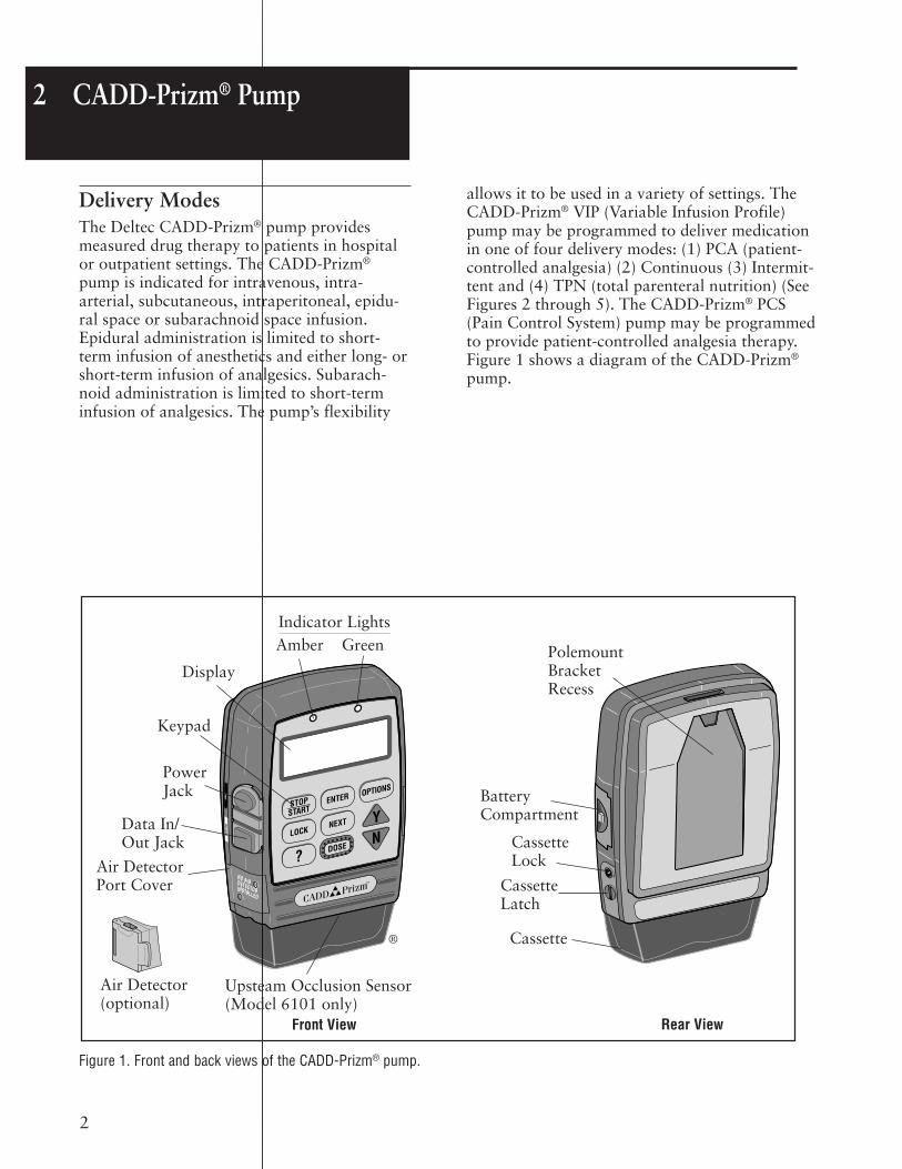
2 CADD-Prizm® Pump
Figure 1. Front and back views of the CADD-Prizm® pump.
Indicator LightsAmber Green
Display
Keypad
PowerJack
Data In/Out Jack
Air DetectorPort Cover
Air Detector(optional)
Front View Rear View
PolemountBracketRecess
BatteryCompartment
CassetteLock
Cassette
CassetteLatch
Delivery ModesThe Deltec CADD-Prizm® pump providesmeasured drug therapy to patients in hospitalor outpatient settings. The CADD-Prizm®
pump is indicated for intravenous, intra-arterial, subcutaneous, intraperitoneal, epidu-ral space or subarachnoid space infusion.Epidural administration is limited to short-term infusion of anesthetics and either long- orshort-term infusion of analgesics. Subarach-noid administration is limited to short-terminfusion of analgesics. The pump’s flexibility
allows it to be used in a variety of settings. TheCADD-Prizm® VIP (Variable Infusion Profile)pump may be programmed to deliver medicationin one of four delivery modes: (1) PCA (patient-controlled analgesia) (2) Continuous (3) Intermit-tent and (4) TPN (total parenteral nutrition) (SeeFigures 2 through 5). The CADD-Prizm® PCS(Pain Control System) pump may be programmedto provide patient-controlled analgesia therapy.Figure 1 shows a diagram of the CADD-Prizm®
pump.
®
Upsteam Occlusion Sensor(Model 6101 only)

3
Figure 2. PCA mode delivery profile.
Clinician Bolus(used here as a loading dose)
Demand DosesContinuous Rate
Time
Dos
age
Figure 3. Continuous mode delivery profile.
Figure 4. Intermittent mode delivery profile.
Figure 5. TPN mode delivery profile.
PCA Delivery ProfileThe PCA (patient-controlled analgesia) deliverymode is used for therapies that require acontinuous rate of infusion, patient-controlleddemand doses or both, such as patient-controlled analgesia.
Continuous Mode Delivery ProfileThe Continuous delivery mode allows theinfusion of drug at a constant, programmedrate.
Intermittent Mode Delivery ProfileThe Intermittent delivery mode allows theinfusion of a specific volume of drug at aregular programmed interval.
TPN Mode Delivery ProfileThe TPN (total parenteral nutrition) deliverymode allows the infusion of nutritional solu-tions or other fluids, with optional tapering atthe beginning and end of infusion, and anoptional KVO.
DeliveryRate
(ML/HR)
TimeContinuous Delivery
TimeIntermittent Delivery
KVO
(optional)
DELAYSTART
(optional)
PERIOD
KVO
(optional)
PERIOD
CYCLE
DeliveryRate
Infusion Period
Time
INFUSION VOLUME
KVO Rate5 ML/HR
Delivery Rate
(ML/HR)
Taper-Down Period (Optional)
Taper-UpPeriod (Optional)

4
Concentration Demand Dose Clinician Bolusmg/ml increment max. increment max.
0.1 0.01 0.99 0.01 20.2 0.02 1.98 0.02 40.3 0.03 2.97 0.03 60.4 0.04 3.96 0.04 80.5 0.05 4.95 0.05 101 0.05 9.9 0.05 202 0.10 19.8 1.10 403 0.15 29.7 1.15 604 0.20 39.6 0.20 805 0.25 49.5 0.25 100
10 0.50 99.0 0.50 20015 0.75 148.5 0.75 30020 1.00 198.0 1.00 40025 1.25 247.5 1.25 50030 1.50 297.0 1.50 60035 1.75 346.5 1.75 70040 2.00 396.0 2.00 80045 2.25 445.5 2.25 90050 2.50 495.0 2.50 100055 2.75 544.5 2.75 110060 3.00 594.0 3.00 120065 3.25 643.5 3.25 130070 3.50 693.0 3.50 140075 3.75 742.5 3.75 150080 4.00 792.0 4.00 160085 4.25 841.5 4.25 170090 4.50 891.0 4.50 180095 4.75 940.5 4.75 1900100 5.00 999.0 5.00 2000
Milligrams
Table 1. PCA delivery mode: continuous rate scroll ranges.
Table 2. Demand dose, clinician bolus scroll ranges,milligrams
Concentration Demand Dose Clinician Bolusmcg/ml increment max. increment max.
1 0.05 9.9 0.05 202 0.10 19.8 0.10 403 0.15 29.7 0.15 604 0.20 39.6 0.20 805 0.25 49.5 0.25 100
10 0.50 99.0 0.50 20015 0.75 148.5 0.75 30020 1.00 198.0 1.00 40025 1.25 247.5 1.25 50030 1.50 297.0 1.50 60035 1.75 346.5 1.75 70040 2.00 396.0 2.00 80045 2.25 445.5 2.25 90050 2.50 495.0 2.50 100055 2.75 544.5 2.75 110060 3.00 594.0 3.00 120065 3.25 643.5 3.25 130070 3.50 693.0 3.50 140075 3.75 742.5 3.75 150080 4.00 792.0 4.00 160085 4.25 841.5 4.25 170090 4.50 891.0 4.50 180095 4.75 940.5 4.75 1900100 5.00 990.0 5.00 2000200 10.00 1980.0 10.00 4000300 15.00 2970.0 15.00 6000400 20.00 3960.0 20.00 8000500 25.00 4950.0 25.00 10000
Micrograms
Table 3. Demand dose, clinician bolus scroll ranges,micrograms
Units Starting Increment Maximum
Milliliters 0.10 0.10 30.00
Milligrams & 10% of Mg only: Values between 0.01 and 0.5: 0.01 ConcentrationMicrograms concentration Mcg only: Values between 0.1 and 0.5: 0.1 x 30
Values between 0.5 and 100: 0.1Values between 100 and 1000: 1.0Values greater than 1000: 10.0
PCA Delivery Mode Scroll Ranges
Demand Dose Clinician Bolusincrement max. increment max.
0.05 9.9 0.05 20
Milliliters
Table 4. PCA delivery mode: Demand dose, clinicianbolus scroll ranges, milliliters

5
Specifications (Nominal)
General Pump Specifications
ResolutionMedicaton Cassette reservoir or CADD®
administration set, 0.050 ml/pump strokenominalCADD-Prizm® high volume administrationset, 0.100 ml/pump stroke nominal
Size4.4 cm x 10.4 cm x 14.1 cm (1.7 in. x 4.1in. x 5.6 in.) excluding cassette or otheraccessories
Weight568 g (20 oz.) including 9-volt battery andempty 100-ml Medication Cassette reservoir,excluding other accessories
Pump AlarmsLow battery power; depleted battery power;external power source low, faulty, depleted;pump stopped; pump fault; low reservoirvolume; high delivery pressure; air in line;air detector faulty or detached (only with theuse of the optional air detector); air detectorport cover detached; delivery too slow; keystuck; cassette detached or unlocked; printfailure, upstream occlusion (model 6101 only)
Bolus Volume at Occlusion Alarm Pressure0.050 ml resolution sets/reservoirs:< 0.25 ml0.100 ml resolution sets: < 2.0 ml
Power Sources9-volt alkaline or lithium battery such asDURACELL® Alkaline MN 1604 orULTRALIFE® Lithium U9VL; Power Packreorder number 21-3801; AC adapter.An internal battery powers the clock. Whenit is depleted, it cannot reliably maintain theclock time. This battery must be replaced bythe manufacturer. The internal battery hasan expected life of 5 years.
System* Operating Temperature+2°C to 40°C (36°F to 104°F)
System* Storage Temperature-20°C to 60°C (-4°F to 140°F)
Power Pack Charging Temperature+10°C to 35°C (50°F to 95°F)
System* Delivery Accuracy± 6% (nominal)
High Pressure Alarm18 ± 9 psi
Air Detector AlarmSingle bubble greater than 0.100 ml
PCA Delivery Mode SpecificationsReservoir Volume
1 to 9999 or Not In Use; programmable in1 ml increments, displayed in 0.1 ml incrementsDefault: 1 ml
UnitsMilliliters (ml), milligrams (mg), micrograms (mcg)Default: milligrams
ConcentrationMg/ml: 0.1, 0.2, 0.3, 0.4, 0.5, 1, 2, 3, 4, 5, 10,15, ... 95, 100Mcg/ml: 1, 2, 3, 4, 5, 10, 15, ...95, 100, 200,300, 400, 500Default: 1 mg/ml
Continuous Rate0 to 30 ml/hr (or the mg or mcg equivalent)(See Table 1 for scroll ranges)Default: 0 mg/hr
Demand Dose0 to 9.9 ml (or the mg or mcg equivalent)(See Tables 2, 3 and 4 for scroll ranges)Default: 0 mg/hrDelivery rate (Continuous Rate + DemandDose): 125 ml/hr nominal
Demand Dose Lockout5 minutes to 24 hours in the following increments:1 minute for values between 5 and 20 minutes5 minutes between 20 minutes and 24 hoursDefault: 5 minutes
Max Doses Per Hour1 to 12 doses in 1 dose increments (will also belimited by the Demand Dose Lockout value)Default: 1
Demand Doses Given0 to 999
Demand Dose Attempts0 to 999
*System is defined as a CADD-Prizm® pump with an attached Medication Cassette reservoir and CADD® extension set with integralanti-siphon valve, or an attached CADD® administration set with integral or add-on anti-siphon valve.

6
Given0 to 99999.99 in 0.01 unit increments
Clinician Bolus0.1 ml to 20.00 ml (or mg or mcg equiva-lent) (See Tables 2, 3 and 4 for scrollranges) Delivery rate (Continuous Rate +Clinician Bolus): 125 ml/hr nominal
Continuous Delivery Mode SpecificationsReservoir Volume
1 to 9999 or Not In Use; programmable in1 ml increments, displayed in 0.1 mlincrementsDefault: 1 ml
Continuous Rate0.1 to 350 ml/hr in the following increments:0.1 for values between 0.1 and 1001 for values between 100 and 350Default: 0 ml/hrUse 9-volt battery for rates up to 250 ml/hr; use power pack or AC adapter for ratesup to 350 ml/hr
Given0 to 99999.9 in 0.1 unit increments
TPN Delivery Mode SpecificationsReservoir Volume
10.0 to 9990 or Not In Use; program-mable in 1 ml increments, displayed in 0.1ml incrementsDefault: 10 ml
Infusion Volume10 to 9990 ml in 10 ml increments:Default: 10 ml
Infusion Period0 hrs 10 min to 99 hrs 50 min in 10minute increments:Default: 1 hr 0 min
Taper-Up Period0 hrs 0 min to 99 hrs 40 min in 10 minuteincrements:Default: 0 hrs 0 min
Taper-Down Period0 hrs 0 min to 99 hrs 40 min in 10 minuteincrements:Default: 0 hrs 0 min
Plateau RateCalculated by pump; 10 to 350 ml/hrUse 9-volt battery for rates up to 250 ml/hr;use power pack or AC adapter for rates up to350 ml/hr
KVO RateCalculated by pump: 1/10 of Plateau Rate upto 5 ml/hr
Given0 to 99999 in 0.1 unit increments
Intermittent Delivery Mode SpecificationsReservoir Volume
1 to 9999 or Not In Use; programmable in1 ml increments, displayed in 0.1 ml incrementsDefault: 1 ml
Dose Volume0.1 to 1000 ml in the following increments:0.1 for values between 0.0 and 1001 for values between 100 and 1000Default: 0.0 ml
Dose Duration1 min to 24 hrs in the following increments:1 minute for values between 1 min and 10 min5 minutes for values above 10 minDefault: 30 minDuration is limited by Dose Volume so thatrate does not exceed 350 ml/hr. Use 9-voltbattery for rates up to 250 ml/hr; use powerpack or AC adapter for rates up to 350 ml/hr
Dose Cycle10 min to 96 hrs in 5 minute increments:Default: 4 hrs
KVO Rate0 to 10 ml/hr in 0.1 ml/hr incrementsDefault: 0 ml/hr
Next Dose Start Time10 min to 96 hrs X min (where X equals a 10minute increment in the 96th hour) or Imme-diate; programmable in 10 minute incrementsDefault: Immediate
Given0 to 99999.9 in 0.1 unit increments
Time RemainingDose and Cycle display in 1 minute increments

7
Options SpecificationsImmediate Taper-Down (TPN)
0 to time remaining in the infusion period,in 10 minute increments (defaults to thecurrently programmed Taper-Down)
AutoLockNot In Use, LL1 or LL2
Time00:00 to 23:59
Air DetectorTurned On or Turned Off
Event Log0 to 500 events
Extended HistoryUp to 48 hours in 1 hour increments
Biomed Toolbox SpecificationsMicrograms
On or Off
Extended HistoryOn or Off
Max Dose per HourOn or Off(PCA software rev. 6210G or higher only)
PM (Preventive Maintenance) Reminder1 to 24 months in 1 month increments,Not In Use
Custom Lock Level CodeDate Format
US Standard (mm/dd/yy) or EuropeanStandard (dd/mm/yy)
Power Source DisplayAlways display or only Low Battery
Upstream SensorOn or Off(Model 6101 only)
Air Detector RequiredRequired or Not Required
Compatible Reservoirs andAdministration Sets• 50-ml or 100-ml Medication Cassette reser-
voir, used with the CADD® extension setwith anti-siphon valve.
• CADD® administration set with integralanti-siphon valve, with or without bag spike
(allows use of flexible plastic bag or sterile vialwith injector)
• CADD® administration set with add on anti-siphon valve and bag spike (allows for gravitypriming before attaching the add on anti-siphon valve)
• CADD-Prizm® high volume administration setwith add on anti-siphon valve, with or withoutair-eliminating filter
Remote Dose CordDeltec provides a Remote Dose Cord for the PCAdelivery mode, which is an extension of theDOSE key. The push button switch is a SinglePole Double Throw (SPDT) which operates in thesame manner as the DOSE key. When the Re-mote Dose Cord is attached to the pump, thepatient may press either the Remote Dose buttonor the DOSE key to receive a Demand Dose. Theclinician may also use either the Remote Dosebutton or the DOSE key to deliver a clinicianbolus. For easy access, the Remote Dose cordmay be fastened to the patient’s clothing orbedsheet with the attached clip.
NOTE:
To detach the Remote Dose cord from thepump, grasp the Remote Dose cord connectorand pull back using a straight, steady motion.Do not twist or turn the connector, or use anyinstrument to remove it.
For additional specifications refer to theOperator’s Manual provided with the product.

8
Battery Compatibility
Recommended BatteriesNine-volt alkaline or lithium batteries arerecommended for use in the CADD-Prizm®
pump. Carbon-zinc, mercury, nickel-cadmium,or zinc-air 9-volt batteries should not be used.
Battery LifeThe CADD-Prizm® pump has been designed toprovide optimal battery life. The expectedbattery life in the CADD-Prizm® pump dependson the following factors:
• Programmed delivery rate
• Operating temperatures
• Frequency of display backlighting
• Frequency of printing
• Battery type and brand
• Battery age
DURACELL® Alkaline Battery LifeThe following tables may be used to predicttypical alkaline battery life at different deliveryrates when an alkaline battery is used in theCADD-Prizm® pump. As expected, battery lifedecreases as the delivery rate increases. Thesetables are based on laboratory tests using freshDURACELL® alkaline batteries in CADD-Prizm®
pumps while the pumps were operating at roomtemperature.
Actual battery life may be significantly shorterdepending on the operating temperature andthe storage conditions of the battery.
Battery life is shortened significantly at verylow operating temperatures. For example, at0°C (32°F), an alkaline battery will yieldapproximately 30% of its normal capacity.
Alkaline batteries do not need to be stored in arefrigerator. After four years of storage at 21°C
3 Batteries
(70°F), an alkaline battery retains approxi-mately 86% of its original capacity. Battery lifewill be shorter if the battery is stored aboveroom temperature. An alkaline battery stored at43°C (110°F) will be down to approximately80% of its capacity within one year.
Recommended storage conditions are 10°C to25°C (50°F to 77°F) with no more than 65%relative humidity noncondensing.
The following tables are based on laboratorytests conducted at room temperature using freshDURACELL® alkaline batteries and a CADD®
administration set. Actual battery life will varydepending on the brand of battery, battery shelflife and temperature conditions.
ULTRALIFE® Lithium Battery LifeThe following tables may be used to predicttypical lithium battery life at different deliveryrates when a lithium battery is used in theCADD-Prizm® pump. As expected, battery lifedecreases as the delivery rate increases. Thesetables are based on laboratory tests using freshULTRALIFE® lithium batteries in CADD-Prizm®
pumps while the pumps were operating at roomtemperature.
Actual battery life may be significantly shorterdepending on the operating temperature andthe storage conditions of the battery. Lithiumbattery life is dependent upon the temperatureand relative humidity of storage. Recommendedstorage conditions are less than 20°C (68°F)with a desiccant to ensure less than 10%relative humidity.
The following tables are based on laboratorytests conducted at room temperature using freshULTRALIFE® lithium batteries and a CADD®
administration set. Actual battery life dependsupon the brand of battery selected, theparticular battery selected, battery shelf life,and temperature conditions. Deltec’s testingindicates a large variability in battery life.

9
Rate Life Volume0.4 ml/hr 120 hrs 48 ml10 ml/hr 86 hrs 860 ml30 ml/hr 37 hrs 1110 ml50 ml/hr 26 hrs 1300 ml
100 ml/hr 13 hrs 1300 ml200 ml/hr 14 hrs 2800 ml350 ml/hr 7 hrs 2450 ml
Rate Life Volume0.4 ml/hr 212 hrs 85 ml10 ml/hr 161 hrs 1610 ml30 ml/hr 79 hrs 2370 ml50 ml/hr 60 hrs 3000 ml
100 ml/hr 30 hrs 3000 ml200 ml/hr 32 hrs 6400 ml350 ml/hr 17 hrs 5950 ml
Table 4. 9-volt Alkaline-type batteries used with the CADD-Prizm® pump.
Table 5. 9-volt Lithium-type batteries used with the CADD-Prizm® pump.
Table 6. EPS System used with the CADD-Prizm® pump.
Continuous and PCA Delivery Battery Life (Max Delivery Rate PCA Mode 30 ml/hr)Note: Results are without air detector.
Rate Life Volume100 ml/hr 64 hrs 6400 ml200 ml/hr 67 hrs 13400 ml350 ml/hr 39 hrs 13650 ml
10
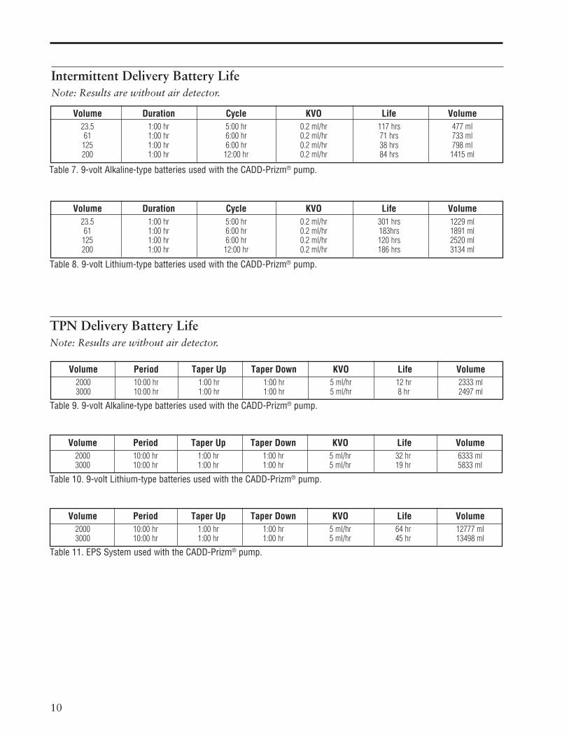
Intermittent Delivery Battery LifeNote: Results are without air detector.
TPN Delivery Battery LifeNote: Results are without air detector.
Volume Duration Cycle KVO Life Volume23.5 1:00 hr 5:00 hr 0.2 ml/hr 117 hrs 477 ml61 1:00 hr 6:00 hr 0.2 ml/hr 71 hrs 733 ml
125 1:00 hr 6:00 hr 0.2 ml/hr 38 hrs 798 ml200 1:00 hr 12:00 hr 0.2 ml/hr 84 hrs 1415 ml
Volume Duration Cycle KVO Life Volume23.5 1:00 hr 5:00 hr 0.2 ml/hr 301 hrs 1229 ml61 1:00 hr 6:00 hr 0.2 ml/hr 183hrs 1891 ml
125 1:00 hr 6:00 hr 0.2 ml/hr 120 hrs 2520 ml200 1:00 hr 12:00 hr 0.2 ml/hr 186 hrs 3134 ml
Table 8. 9-volt Lithium-type batteries used with the CADD-Prizm® pump.
Table 7. 9-volt Alkaline-type batteries used with the CADD-Prizm® pump.
Volume Period Taper Up Taper Down KVO Life Volume2000 10:00 hr 1:00 hr 1:00 hr 5 ml/hr 12 hr 2333 ml3000 10:00 hr 1:00 hr 1:00 hr 5 ml/hr 8 hr 2497 ml
Volume Period Taper Up Taper Down KVO Life Volume2000 10:00 hr 1:00 hr 1:00 hr 5 ml/hr 32 hr 6333 ml3000 10:00 hr 1:00 hr 1:00 hr 5 ml/hr 19 hr 5833 ml
Volume Period Taper Up Taper Down KVO Life Volume2000 10:00 hr 1:00 hr 1:00 hr 5 ml/hr 64 hr 12777 ml3000 10:00 hr 1:00 hr 1:00 hr 5 ml/hr 45 hr 13498 ml
Table 9. 9-volt Alkaline-type batteries used with the CADD-Prizm® pump.
Table 10. 9-volt Lithium-type batteries used with the CADD-Prizm® pump.
Table 11. EPS System used with the CADD-Prizm® pump.

11
4 Construction
The pump’s housing is made of a special highimpact plastic designed to reduce interferencefrom electromagnetic fields and to dissipateelectrostatic discharge. It is composed of twosections: the base and cover housing. Thepump housing is sealed to ensure that thepump is water resistant. The battery compart-ment is not water resistant.
NOTE:
The CADD-Prizm® ambulatory infusionpump is water resistant, but not waterproof.
The battery compartment is accessed through aremovable door on the side of the base hous-ing. Within the battery compartment is spacefor the battery and the two battery contacts.
The Medication Cassette reservoir or theadministration set is attached to the bottom ofthe pump by inserting the two hooks on thecassette into the mating hinge pins on the pump.The pump and the reservoir or the administra-tion set are then placed in an upright positionon a firm, flat surface. The reservoir or theadministration set can be latched in place byinserting a coin in the slot on the pump’slatching button, pushing the button in, andturning the button one-quarter turn counter-clockwise. The reservoir or the administrationset is locked into place by inserting a key intothe pump’s lock and turning the lock one-quarter turn counterclockwise.
NOTE:
The cassette lock must be unlocked beforeattempting to unlatch the disposable.
NOTE:
The Medication Cassette reservoir and theadministration set are intended for singleuse only.
The keyboard, located on the front housing, iscomposed of nine membrane switches and issealed against moisture. All of the keys containdomes to provide a tactile feel when the key ispressed. The keyboard keys are sensed by thepump’s microprocessor.
The custom Liquid Crystal Display (LCD), alsolocated on the front housing, shows the pumpstatus and programmed settings. The dotmatrix display consists of 21 character col-umns with 4 rows of characters, and is selectedby the pump’s microprocessor according tostatus conditions and keyboard entries.
The microprocessor and other circuitry whichcontrol the pump are located on two printedcircuit boards. The microprocessor boardcontains the Central Processing Unit (CPU)and its associated circuitry, motor drivercircuitry, and other miscellaneous circuitry.The LCD board contains the Liquid CrystalDisplay with its associated circuitry, and thebacklight module with its associated circuitry.
The pumping mechanism subassembly containsthe motor, gear train, camshaft, valves,expulsor, sensing disk, infrared light source,infrared detector, occlusion sensor, cassettesensors, lock and latch. Via the motor drivercircuitry, the pump’s microprocessor controlsmotor rotation.
Two external port connectors are utilized forcommunication and external power input. Oneof these connectors, the data in/out jack, isused for attachment of the Remote Dose cord.This enables the patient to use either of twooptions to begin a Demand Dose when usingthe PCA delivery mode: (1) the Remote Dosebutton; or (2) the DOSE key.
This jack can also be connected to an externalprinter via the interface cable. With this feature,the patient or clinician can print various pumpreports. The second port is for external powerconnection. This port, the power jack, canreceive input from either an AC adapter or theExternal Power Source rechargeable power pack.
Connections between the printed circuit boardsare designed for ease of manufacturing andserviceability. The keyboard is connected to themicroprocessor board via a flex circuit tail.Flexible circuitry and discrete wires connectthe pumping mechanism, motor, and sensors tothe printed circuit boards.

12
5 Theory of Operation
Keyboard CircuitryThe CADD-Prizm® pump is controlled by amicroprocessor. The actions of the micropro-cessor are controlled by a program, which iscontained in the memory.
Commands are issued to the microprocessorfrom the user via the nine keys on the key-board and the Remote Dose cord. The keys onthe keyboard feed individually into the GateArray on the microprocessor board. A keyclosure applies a ground to the associatedinput of the Gate Array. Key debounce cir-cuitry resident in the Gate Array provides aclean output signal to the microprocessor forthe duration of the key closure. The micropro-cessor reads keyboard status by accessingspecial memory locations in the Gate Array.
The Remote Dose button consists of an SPDTswitch with its own dedicated input to themicroprocessor circuitry. The switch has acommon input line and two output signallines. The two signal lines are complementarysuch that one line is always logic high and theother is always low. When the Remote Dosebutton is pressed, both signal lines change to thealternate logic state. This redundancy prevents asingle line failure from starting a dose delivery.
Data Memory EEPROMMany settings of the pump’s delivery andrecord keeping parameters are stored by themicroprocessor in an Electrically ErasableProgrammable Read Only Memory(EEPROM). Data to and from the memory ispresented serially. Whenever the microproces-sor uses data from the EEPROM, the data ischecked for validity.
Battery Backed RAMAdditional settings of the pump’s delivery andrecord keeping parameters are stored in abattery backed Random Access Memory(RAM). Battery backup is provided by twoprinted circuit board-mounted lithium batter-
ies. These batteries are designed to provide aminimum of five years of memory retentionduring normal pump usage. Whenever themicroprocessor uses data from the RAM, thedata is checked for validity.
Time Base CircuitryAn accurate 3.6864 MHz timebase is providedby a quartz crystal. The 3.6864 MHz signal isconnected to the microprocessor, where it isfrequency-divided to access the programmemory at a cycle rate of 921 kHz.
In addition, an accurate 32.768 kHz timebaseis provided by a second quartz crystal. The32.768 kHz signal is used for the real timeclock.
LCD CircuitryThe high-impedance, low-power, specialdrive signals for the liquid crystal display areprovided by the LCD-drivers. Each alpha ornumeric character on the LCD is formed bydarkening combinations of dots. Commandsto display dots are issued via data buscommands to the LCD-drivers by themicroprocessor.
The LCD circuit also contains a power supplywhich provides bias voltage to the LCD panel.This voltage controls the relative brightness ofthe characters. Additional circuitry allows themicroprocessor to disable the LCD when notin use in order to conserve battery power.
A two brightness level LCD backlight isprovided to improve LCD viewing under lowlight conditions. When the microprocessorenables the LCD, it also enables the lowbrightness backlight. Low brightness is used toconserve battery power. If the AC adapter isconnected, the microprocessor will enable thehigh brightness backlight since this does notconsume power from the battery.
The backlight automatically shuts off when theLCD is turned off.

13
LED Status IndicatorsAn amber and a green Light Emitting Diode(LED) are provided under the pump’s frontpanel overlay to provide pump status to theuser. Under software control, the LEDs caneither flash at a low duty cycle or be on con-tinuously. A flashing indicator typically indi-cates a normal mode of operation and a steady“on” indicator typically indicates a faultcondition.
Flash PROM TechnologyProgram memory for the pump is stored inFlash Programmable Read Only Memory(Flash PROM). This type of memory allowsmodification of the contents without physicallyremoving the device from the circuit board.Under certain circumstances, the program canalso be downloaded through the I/O port onthe side of the pump. Several layers of redun-dancy in the programming system preventaccidental erasing or modification of thePROM.
Gate Array CircuitryThe Gate Array contains circuitry whichcontrols memory address decoding, keyboarddebounce, Light Emitting Diode (LED) indica-tor status, LCD command buffering, BatteryBacked RAM interface, and miscellaneoussignal line buffering functions.
Audible Alarm CircuitryAudible alarm circuitry consists of a piezoelectric disk and independent oscillator. Thedisk flexes or bends in resonance with theoutput of the oscillator. The piezo disk ismounted to the pump housing to enhancesound level. The oscillator which drives thepiezo disk is capable of providing two drivingfrequencies. The low frequency is in the rangeof 700 to 1500 Hz and the high frequency is inthe range of 1600 to 2500 Hz. The micropro-cessor controls the audible alarm via controllines from the Gate Array. When the micropro-cessor selects both the low and high frequencycontrol lines, the audible alarm enters a warblemode where it oscillates between the low and
high frequency sound at a rate of 0.8 and 2Hz. Low battery voltage detection and watch-dog timer circuitry also have the ability toenable the audible alarm via the Gate Array.
Watchdog Timer CircuitWatchdog timer circuitry is provided to moni-tor the status of the microprocessor anddisable the motor and enable the audible alarmif the microprocessor fails to function properly.The microprocessor must strobe the watchdogcircuit at least once every second in order toprevent the watchdog from performing its resetfunction. The reset output from the watchdogcircuit is a pulse output. This acts to “jumpstart” the microprocessor. This unique featureallows the microprocessor to test the watchdogcircuit on every power-up. By setting a flag inmemory and not strobing the watchdog, themicroprocessor can force a watchdog time-out.After being reset, the microprocessor checksthe status flag to see if this was a time-out test.If so, the microprocessor continues normalpower-up activities. If the reset occurred whenthe microprocessor was not expecting it, themicroprocessor traps the event, sounds theaudible alarm and displays an error messageon the LCD.
Motor Driver/Motor WatchdogCircuitMotor drive circuitry is composed of a series ofpower FET transistors, passive components,and two voltage comparators. Built into themotor drive circuitry is an RC timer whichtimes how long the motor runs each time it isturned on. If the motor runs for more than anaverage of 4 seconds, the circuit will time outand disable the motor. A unique feature of thiscircuit is that control lines to and from themicroprocessor circuit allow the microproces-sor to perform a complete functional test of themotor drive circuit without running the motor.The microprocessor performs this test functionevery several minutes to assure its continuedfunctionality. An input from the watchdogcircuit prevents motor operation if the watch-dog timer expires.
Rotation of the motor is sensed by the micro-processor via an infrared-sensitive photo

14
detector. An infrared light source is mountedso that its light beam illuminates the infrareddetector. An opaque flag is mounted concentri-cally to the camshaft and rotates with it be-tween the infrared light source and detector.When the flag interrupts the light beam, theoutput of the detector is sensed by the micro-processor via an input port bit. Power to theinfrared LED light source is controlled by themotor driver circuit and is off when the motoris not running to conserve battery life.
In the microprocessor software, multiplechecks are made on motion of the camshaft.When the motor is commanded to start, theinfrared sensor must show that half a revolu-tion has occurred within five seconds and thatthe motor has stopped when half a rotationwas completed. In addition, no camshaftrotation can take place when the motor hasnot been commanded to run.
Power CircuitryPower for the pump is normally supplied by a9-volt alkaline battery, 9-volt lithium battery,or AC adapter. These types of batteries have afairly low internal resistance over their dis-charge range, which will keep power supplynoise low. Other types of batteries, such ascarbon-zinc, exhibit high internal resistance,especially near depletion. A voltage dropacross the internal resistance occurs whencurrent is drawn by the motor during pumpactivations. This current is demanded in shortpulses when the motor is first turned on andgenerates large spikes in the battery voltage.This noise can cause the low battery detectioncircuit to shut down the pump.
The motor driver circuit power is taken di-rectly from the battery, but the microprocessorand its associated circuitry requires closelyregulated and filtered 5-volt power which issupplied from the micropower voltage regula-tor. This regulator will supply 5-volt poweruntil its input voltage is approximately 5.3volts. After that point, the output of theregulator will follow the input voltage down.
Voltage Reference CircuitA voltage reference circuit provides a constantDC voltage to the microprocessor Analog toDigital Converter (ADC). By reading this inputand comparing the value to a predeterminedrange, the microprocessor can validate theaccuracy of the 5-volt power supply. Variationsin the 5-volt supply left undetected can resultin inaccuracy in the low battery alarm setpoints and variations in other calculated values.
Table 12. CADD-Prizm® pump low battery conditions.
Voltage CADD® Pump StatusTrip Point*
>7.0V No alarm
6.4–7.0V* Transition to low batterycondition; battery lowmessage appears; 3 beepsevery 5 min.†
6.0–6.6V* Transition to depletedbattery condition; batterydepleted message appears;continuous alarm††
5.25–5.95V Hardware reset occurs.Pump continues to indicatedepleted battery condition.
* Voltage ranges are due to componenttolerances. Actual trip values are guaran-teed to be non-overlapping.
† The pump emits 3 beeps every 5 minutes, and themessage “9 Volt Battery Low” appears on the pump’sdisplay, indicating that the battery power is low, but thepump is operable.
†† The pump emits a continuous, variable-tone alarm,and the message “9 Volt Battery Depleted” appears onthe display, the battery power is too low to operate thepump, and pump operation has stopped.
Pumping MechanismThe pumping mechanism is linear peristalticwith two active valves. Pumping occurs whenthe expulsor presses on the reservoir pumptubing in sequence with the inlet and outletvalves. At rest, the outlet valve is pressingdown fully on the tubing and the expulsor andinlet valve are retracted. (See Figure 7.)

15
When the microprocessor commands the mecha-nism to pump, the camshaft begins to rotate,thus controlling the following pump cycle:
1. The inlet valve closes.
2. In synchrony with the expulsor movingdown to compress the tubing, the outletvalve opens, expelling 0.050 ml of fluid (or0.100 ml of fluid with a CADD-Prizm® highvolume administration set) toward thepatient.
3. The outlet valve closes.
4. The inlet valve opens as the expulsor isretracted, causing fluid from the reservoir toagain fill the pump tubing segment.
5. The camshaft rotation stops after half arevolution and the cycle is completed.
Pumping CharacteristicsIf the fluid path to the patient becomes blocked,the pump tubing will expand as pumpingoccurs. When there has been an amount ofinflation corresponding to 124 ± 62 kPa(1.24 ± 0.62 bar, 18 ± 9 psi), the occlusionanalog sensor trips, whereupon the micropro-cessor stops the pump mechanism and issuesvisual and audible alarms. Thus the maximumpressure which can be developed is 186 kPa(1.86 bar, 27 psi).
To deliver the amount of drug specified by theparameter settings, the pump’s microprocessor
causes the pump mechanism to deliver 0.05 ml(or 0.1 ml with a CADD-Prizm® high volumeadministration set) fluid “pulses” timedaccording to the desired rate. At rates higherthan 3 ml/hr, 2 pulses in succession will begiven. Thus, to deliver 20 ml/hr, for example,the microprocessor solves these equations:
Mechanism activations per hr
= 20 ml per hr/0.1 ml per activation
= 20/0.1
= 200
Time (seconds) between activations
= 3600 sec per hr/number of activations per hr
= 3600/200
= 18
Rate Volume(ml/hr) Resolution (ml)
Cassette or 0 - 3 0.050 Admin Set 3.1 - 125 0.100
Hi Vol 0 - 3 0.100 Admin Set 3.1 - 350 0.200
The microprocessor uses its timer circuits toaccurately time the 18 seconds (in this ex-ample) between mechanism activations. Thetimebase accuracy is ultimately determined bythe 3.6864 MHz quartz crystal oscillator.
Figure 7. A simulated pumping mechanism in a CADD-Prizm® pump.
Lock Button
Latch Button
Pressure PlateInlet ValveOutlet Valve
Pump Tubing
Cassette Hinge
Occlusion Sensor
Expulsor
Pump Housing
CamshaftMotor

16
Air DetectorThe air detector is designed to detect air in theoutlet tubing fluid path. The air detector isdetachable if not needed. The CADD-Prizm®
pump automatically detects the presence of theair detector and will automatically turn thesensor on when powered up in LL0.
When the optional air detector is installed, theBiomed Toolbox feature allows the air detectorto be “required” or “not required.” When the airdetector is not required, it can be “turned on” or“turned off” using the Options menu. When theair detector is required, the option for turningthe air detector on or off will not be available.When the air detector is turned on, the pumpwill detect the presence of air in the outlet tubingfluid path. If the air detector settings are “notrequired” and “turned off,” it will default to“turned on” each time the pump powers up inLock Level 0.
The air detector is compatible with all of thereservoirs and sets indicated for use with theCADD-Prizm® pump, and all pump accessories.It is powered directly from the CADD-Prizm®
pump and no additional power is required.
SpecificationsThe air detector will alarm when it senses asingle air bubble greater than 100 microliters(0.1 milliliters.)
ConstructionThe air detector housing is made of a specialhigh impact plastic and has a metalized filmcoating on the inside surface to reduce interfer-ence from electromagnetic fields. The air detectoris composed of a single base compartment with adetachable door. It is sealed against the pumphousing to ensure the overall assembly is waterresistant. The air detector is mounted to thepump housing with two screws, and electricallyconnected with a ten pin connector.
Theory of OperationThe air detector consists of sensor electronicsand two ultrasonic transducers positioned onopposite sides of the tubing. One transducer actsas an acoustic transmitter and the other as anacoustic receiver. Air detection occurs when airin the fluid path causes a reduction in the signallevel to the receiver. When the signal is inter-rupted for a preset length of time, the sensingcircuitry sends a signal to the microprocessorindicating air in the fluid path. To maximize thereliability of the system and to reduce falsealarms, the transmitted signal is swept over afrequency range. This accommodates varyingresonance frequencies of the transducer andreduces sensitivity to tubing tolerances and othermechanical variations.
Upstream Occlusion Sensor
Theory of OperationThe upstream occlusion sensor is a straingauge device capable of detecting pressurechanges in the disposable tubing set. This isaccomplished by using a loading ball or spherelocated on the bottom of the pump. Thisloading ball contacts the pump tubing when atubing set is attached to the pump. Undernormal operation, the pump tube pushesoutward and applies a specified force on thesensor. When an upstream occlusion is present,the upstream tubing collapses pulling awayfrom the sensor reducing the force on thesensor. It is this change of the force that indi-cates an upstream occlusion.

17
6 Safety Features andFault Detection
Hardware Safety FeaturesKey hardware safety features include a watch-dog timer circuit, motor driver and motorwatchdog circuits, cassette ‘type’ sensor circuit,latch/lock sensor circuit, and a voltage detectorcircuit. Each safety circuit performs a uniquefunction to insure the overall safety of thedevice. (See Figure 8.)
Watchdog Timer CircuitThe microprocessor must send an appropriatesignal to the watchdog circuit at least once persecond. If the microprocessor does not, thewatchdog circuit will time out and shut downthe pump controller.
Watchdog timer circuitry is provided to monitorthe status of the microprocessor and disablethe motor and enable the audible alarm if the
microprocessor fails to function properly. Themicroprocessor must strobe the watchdogcircuit at least once every second in order toprevent the watchdog from performing its resetfunction. The reset output from the watchdogcircuit is a pulse output. This acts to “jumpstart” the microprocessor. This unique featureallows the microprocessor to test the watchdogcircuit on every power-up. By setting a flag inmemory and not strobing the watchdog, themicroprocessor can force a watchdog time-out.After being reset, the microprocessor checksthe status flag to see if this was a time-out test.If so, the microprocessor continues normalpower-up activities. If the reset occurred whenthe microprocessor was not expecting it, themicroprocessor traps the event, sounds theaudible alarm and displays an error messageon the LCD.
Figure 8. CADD-Prizm® pump hardware block diagram.
PROGRAMMEMORY
MB
DATAMEMORY
MB
LCD DISPLAY VOLTAGEREFERENCE
MOTORDRIVER
WATCHDOG
REAL-TIMECLOCK
CPU/IO/GATE ARRAY
KEYBOARD
MOTORWATCHDOG
VOLTAGEDETECTOR
SENSORS
AUDIBLEALARM
��
�
�
�
��
�
��
�
��
��
��
��
��
�

18
Motor Driver/Motor Watchdog CircuitMotor drive circuitry is composed of a series ofpower FET transistors, passive components,and two voltage comparators. Built into themotor drive circuitry is an RC timer whichtimes how long the motor runs each time it isturned on. If the motor runs for more than anaverage of 4 seconds, the circuit will time outand disable the motor. A unique feature of thiscircuit is that control lines to and from themicroprocessor circuit allow the microprocessorto perform a complete functional test of themotor drive circuit without running the motor.The microprocessor performs this test functionevery several minutes to assure its continuedfunctionality. An input from the watchdogcircuit prevents motor operation if the watch-dog timer expires.
Cassette ‘Type’ Sensor CircuitThe cassette ‘Type’ sensor system consists ofthree pins protruding from the button of thepump mechanism that interface to the attachedadministration set and associated circuitry.Each type of administration set designed towork with the CADD-Prizm® pump contains aunique ‘code’ programmed into the set vianubs molded into the plastic. When a set islatched to the pump, the nubs press against thepins in the pump mechanism in a patternunique to that set type. Optical detectors andelectronic circuitry on the circuit board encodethis pattern and report the information to themicroprocessor. This feature allows automaticrate selection dependent on the type of setattached. This system also acts as a safetyfeature to detect a damaged or detached set.If, during operation, the microprocessordetects all pins extended, the pump will enableaudible and visual alarms and stop delivery.Redundancy in the pattern prevents single faultfailures from causing over or under delivery offluid. Additional circuitry allows these sensorsto be turned on and off by the microprocessorto conserve battery power. Additionally, controlof sensor power allows the microprocessor totest the sensor inputs in both the powered andunpowered states, thus allowing detection ofsensor fault conditions. Care should be takennot to damage these sensor pins.
Latch/Lock Sensor CircuitLatch and Lock sensors allow the microproces-sor to detect the positions of the latch and lockbuttons. This prevents attempted fluid deliverywhen the set is not correctly latched to thepump. In addition, it allows the microprocessorto stop fluid delivery and enable audible andvisual alarms if the set is unlatched during fluiddelivery. Opposing infrared transmitters andreceivers on both the latch and lock buttonsallow the microprocessor to detect their openand closed positions. Additional circuitryallows these sensors to be turned on and off bythe microprocessor to conserve battery power.Additionally, control of sensor power allowsthe microprocessor to test the sensor inputs inboth the powered and unpowered states, thusallowing detection of sensor fault conditions.
Voltage Detector CircuitLow voltage detection is performed by part ofthe watchdog circuit and by the microprocessorvia software. Three low voltage levels aredetected. The first two levels are detected bysoftware and the third by hardware. The firstlevel to be reached is the Low Battery Warningthreshold which occurs when the batteryvoltage decays to a nominal value of 6.8 volts.An Analog to Digital Converter (ADC) builtinto the microprocessor allows the micropro-cessor, via software, to monitor the batteryvoltage. At the Low Battery Warning thresh-old, the microprocessor enables a periodicseries of beeps and displays a low batterywarning message on the LCD. As the batteryvoltage reaches a nominal value of 6.3 volts,the software disables delivery, places a batterydepleted message on the LCD, and enables aconstant two-tone audible alarm. When thebattery voltage decays to a nominal value of5.6 volts, a hardware reset circuit is triggeredwhich places the microprocessor in reset. Thisprevents ambiguous microprocessor operationwhen the battery voltage continues to decay.The hardware reset continues until the batteryis completely discharged or until it is removed.Once the pump controller goes into lowbattery shutdown, only replacing the oldbattery with a fresh one will clear the condition.

19
Software Safety Features
Hardware-related Software Safety Features
Program Memory CheckAt power up and at regular intervals thereafter,the program memory is tested by calculatinga Cyclic Redundancy Code (CRC) on theprogram and then comparing it with the CRCstored with the program. If the stored andcalculated CRCs do not match, the softwarewill turn on a continuous two-tone audiblealarm and stop all drug delivery.
RAM Memory CheckAt power up, the random access memory ischecked. A particular bit pattern is written toand read from each address in the RAM. If theread data is different from the written data, thesoftware will turn on a continuous two-toneaudible alarm and stop all drug delivery.
Motor Circuit CheckAt power up and at regular intervals thereafter,the motor circuit is checked to ensure that nopower is being applied to the motor unless themotor is actually on. If the software detectspower being applied to the motor at any othertime, it will sound a continuous two-toneaudible alarm and will no longer attempt todeliver medication. During every pumpactivation, the software checks to see whetherthe motor completes one activation. If themotor fails to turn, or fails to complete a cycle,the software will turn on a continuous two-tone audible alarm and stop all drug delivery.
Keyboard Encoder CheckEvery time the software receives data from thekeyboard encoder, it is checked. If the data isnot of the proper form, the software will turnon a continuous two-tone audible alarm andstop all drug delivery. The DOSE key has twoindependent signal lines to prevent single faultfailures.
Data Handling Software Safety Features
Data Stored in RAMBefore use, data associated with delivery andstored in RAM is tested by calculating a CRCon the data and then comparing it with theCRC stored with the data. If the stored andcalculated CRCs do not match, the softwarewill turn on a continuous two-tone audiblealarm and stop all drug delivery.
Data Stored in EEPROMBefore use, data associated with delivery andstored in EEPROM is tested by calculating aCRC on the data and then comparing it withthe CRC stored with the data. If the stored andcalculated CRCs do not match, the softwarewill turn on a continuous two-tone audiblealarm and stop all drug delivery.
Data Stored in NOVRAMBefore use, data associated with delivery andstored in NOVRAM is tested by calculating aCRC on the data and then comparing it withthe CRC stored with the data. If the stored andcalculated CRCs do not match, the softwarewill turn on a continuous two-tone audiblealarm and stop all drug delivery.
Data Used in CalculationsCalculations on data used in some way tocontrol the delivery of drug are performedredundantly. The two calculated values arethen compared. If the two values do not match,the software will turn on a continuous two-tone audible alarm and stop all drug delivery.
Timer Data RegistersThe data stored in the timer control register ischecked at regular intervals. If the data is notcorrect, the software will turn on a continuoustwo-tone audible alarm and stop all drugdelivery.

20
OverviewIf the CADD-Prizm® pump displays an errorcode, a hardware or software fault has beendetected by the microprocessor, and the pumpshould be returned for servicing.
When hardware or software faults are detectedby the microprocessor, pump operation stopsand a continuous, audible alarm will be acti-vated as well as the amber warning LED. Anerror message will be displayed. On the nextpower up, the error code will again be dis-played with the software level (see illustrationbelow). If the error detected was a data fault,the pump will be in Lock Level 2, and all otherprogrammed functions will have defaultvalues. (See the pump’s Operator’s Manual forspecific defaults.)
7 Hardware and SoftwareFault Detection
Error DetectedE(XXXXX)
Order of Error Code Events1. There is a continuous two-tone audible
alarm, a continuous amber indicator light,and the display will read
NOTE:
“XXXXX” is a 5-digit code.
2. To silence the error code alarm, remove thebattery.
3. At the next power-up, the last error code(lec) will be visible on the display. Themicroprocessor will also record an errorcode in the Event Log. The description“Error Detected” along with five digits willappear in the LCD in the Event Log. Thesefive digits will remain in memory and willappear on the Event Log record until 500data writes have occurred or until the modehas been changed. (See “Testing Procedures”starting on page 23 of this manual fordetailed instructions regarding the power-upcheck.) Thus, there is always a record of thelast internal fault detected by the micropro-cessor.
C A D D - P R I Z M 61XX lec XXXXXsn XXXXXXXX 0254-01X625 XXXXX XXXX-X
Terminal Software revision level
Error code Pump model number
Serial number
21
8 Cleaning and InspectionProcedures
Use any of the following solutions to clean thepump and accessories:
• Soap solution
• Benzalkonium chloride concentrate (0.13%)
• Glutaral concentrate, USP (2%)
• 10 percent solution of household bleach (onepart household bleach to nine parts water)
• Alcohol, USP (93%)
• Isopropyl Alcohol, USP (99%)
• PDI – Super Sani-Cloth®
• Mada Medical – MadaCide
1. Dampen a soft, lint-free cloth with cleaningsolution. Apply the solution to exteriorsurface of the pump or accessory. Do notallow the solution to soak into the pump oraccessory.
2. Wipe the entire surface dry with anothersoft, lint-free cloth. Allow the pump to drycompletely before use.
Visual Inspection• Visually inspect the pump for any damage to
the LCD, occlusion sensor seals, valves andexpulsor, reservoir hinge area, latch, lock,cassette sensors (3), keyboard, indicatorlights, power jack, data in/out jack, airdetector port cover or air detector, andhousing. If any damage is noted, the pumpshould be returned for service.
• Check the battery door for proper operation.It should not be broken or damaged. Themating tabs on the pump housing should notbe broken or damaged.
• Examine the battery compartment for dam-age. If the battery contacts appear corroded,clean them with a cotton swab and isopropylalcohol. If the battery contacts appear to bebent or pushed in, straightening may bepossible with a small screwdriver or othersuitable tool. Care must be taken so as not todamage the pump housing or to incur furtherdamage to the contacts.
Inspection RecommendationDeltec recommends annual functional inspec-tion on the CADD-Prizm® pump. The follow-ing inspection and testing procedures should beperformed annually to verify function andaccuracy.
NOTE:
Persons performing the following tests andprocedures should be familiar with theDeltec CADD-Prizm® pump. Please read theOperator’s Manual supplied with the pumpbefore proceeding.
WARNING:
CADD® pumps are sealed units. A broken ordamaged seal will, therefore, be consideredconclusive evidence that the pump has beenmisused and/or altered, which voids any andall warranties. All service and repair ofCADD® pumps must be performed by Deltecor its authorized agents.
Cleaning
CAUTION:
• Do not immerse the pump in cleaningfluid or water. Do not allow solution tosoak into the pump, accumulate on thekeypad, or enter the battery compartment.
• Do not allow solution to enter the datain-out jack or the power jack. Make surethe jack covers are closed before cleaning.
• Do not expose the open air detector portarea of the pump or the connectoropening on the air detector to foreignmaterial, moisture or cleaning fluids. Ifan air detector is not installed on thepump, make sure the air detector portcover is securely attached before cleaning.
• Do not clean the pump with acetone,other plastic solvents, or abrasivecleaners.

22
Mechanical Inspection• Press each key on the keyboard. Each key
should have a distinctive dome feeling. Thekeys should not feel flat.
• Attach the battery door. The battery doorshould fit snugly in place when it is closed onthe pump.
• Attach either a 50- or 100-ml MedicationCassette reservoir or a CADD® administra-tion set to the pump. Check for smoothoperation and a definite “feel” when the latchpulls the reservoir or administration set firmlyagainst the bottom of the pump. The mark onthe latch should be aligned with the solid dot.
• Lock the device by inserting a key into thelock and turn counterclockwise until themark lines up with the solid dot.
• Gently twist and pull on the cassette to makesure it is firmly attached.
NOTE:
In the PCA delivery mode, the cassette mustbe locked in order to start the pump.

23
• Lock the device by inserting a key into thelock and turning counterclockwise until themark lines up with the solid dot. The displayshould show “Cassette Locked.”
• Unlock the device by inserting a key into thelock and turning clockwise until the marklines up with the open dot. The displayshould show “Cassette Unlocked.”
• Unlatch the reservoir by inserting a coin intothe latch slot and turning clockwise until themark lines up with the open dot. The displayshould show “Cassette Unlatched / CloseClamp to Prevent Free Flow.”
Cassette Sensor Check• Attach a 50- or 100-ml Medication Cassette
reservoir to the pump. Latch the cassette tothe pump. The display should show “Reser-voir latched.” NOTE: The message displayeddepends on the type of reservoir or adminis-tration set attached. See Table 13.
• Lock the device by inserting a key into thelock and turning counterclockwise until themark lines up with the solid dot. The displayshould show “Cassette Locked.”
• Unlock the cassette. The display should show“Cassette Unlocked.” Unlatch the cassette.The display should show “Cassette Unlatched /Close Clamp To Prevent Free Flow.”
Functional TestingThe Power-up Check, Latch/Lock Checkand Cassette Sensor Check using aMedication Cassette reservoir or CADD®
administration set can be performed with thepump in any of the four delivery modes.The Cassette Sensor Check using theCADD-Prizm® high volume administrationset can be performed in any delivery modeexcept the PCA delivery mode.
Power-up Check• Insert a battery in the pump and observe the
LCD during power up.
The number values may vary depending on the currentmode and software revision.
• If “lec XXXXX” (last error code with 5 digitnumber) appears on the display prior to thepump reviewing the current program settings,the pump has experienced an electrical ormechanical fault and should be returned forservice. If no error message is immediatelyshown, the pump has powered up normally.The pump should sequentially display all ofthe programmed values. The words “Self TestComplete” should appear, then the text“Power Up Successful” with six audiblebeeps. Continue with the Latch/Lock check.
Latch/Lock Check• Attach a 50- or 100-ml Medication Cassette
reservoir or a CADD® administration set tothe pump. The mark on the latch should bealigned with the solid dot. The display shouldshow that the reservoir or administration setis latched. See Table 13.
9 Testing Procedures
Reservoir Latched The MedicationCassette reservoir hasbeen latched onto thepump.
Admin set Latched The CADD® adminis-tration set has beenlatched onto the pump.
High Volume The CADD-Prizm®
Admin Set Latched high volume adminis-tration set has beenlatched onto the pump.
Table 13.
(excluding PCAdelivery mode)
C A D D - P R I Z M 61XX lec XXXXXsn XXXXXXXX 0254-01X625 XXXXX XXXX-X
Terminal Software revision level
Error code Pump model number
Serial number

24
• Remove the 50- or 100-ml reservoir andattach a CADD® administration set to thepump. Latch the cassette to the pump. Thedisplay should show “Admin Set Latched.”
• Lock the device by inserting a key into thelock and turning counterclockwise until themark lines up with the solid dot. The displayshould show “Cassette Locked.”
• Unlock the cassette. The display should show“Cassette Unlocked.” Unlatch the cassette.The display should show “Cassette Unlatched/Close Clamp To Prevent Free Flow.”
• Remove the administration set and attach aCADD-Prizm® high volume administrationset to the pump (excludes PCA deliverymode). Latch the cassette to the pump. Thedisplay should show “High Volume AdminSet Latched.”
• Lock the device by inserting a key into thelock and turning counterclockwise until themark lines up with the solid dot. The displayshould show “Cassette Locked.”
• Unlock the cassette. The display should show“Cassette Unlocked.” Unlatch the cassette.The display should show “Cassette Unlatched/Close Clamp To Prevent Free Flow.”
NOTE:
The basic electrical and mechanicalfunctions of the CADD-Prizm® pump arethe same for each of the four deliverymodes. Regardless of the delivery mode, thedelivery accuracy and timing circuitryremains unchanged. Although functionaltesting of the CADD-Prizm® pump can beperformed in any mode, the remaining testsare intended to be performed in the PCAdelivery mode. Additional tests may beperformed with the pump in a differentdelivery mode if desired.
The following three checks (LCD, motor andgear train, and Reservoir Volume is Zero alarm)should be performed in the sequence shown.
LCD Check• Remove and reinsert the battery. After a few
seconds, the LCD will display all off pixels(dots) followed by all on pixels. Examine theLCD for missing dark or light pixels.
• Program the pump to the following parameters:
Reservoir Volume: 2.0 mlUnits: MilligramsConcentration: 1.0 mg/mlContinuous Rate: 30.0 mg/hrDemand Dose: 0.0 mgMilligrams Given: 0.0 mg (press the
ENTER key to clear)
• Press the NEXT key until reservoir volume isdisplayed on the LCD. Press the Y or N keyuntil 2.0 ml is displayed. Then press theENTER key. Select Milligrams for units andpress the ENTER key. Select the Concentra-tion of 1.0 mg and press the ENTER key.Select the Continuous Rate of 30.0 mg/hr,then press the ENTER key. Select the DemandDose of 0.0 mg, then press the ENTER key.Clear the Milligrams Given register by press-ing the ENTER key.
Motor and Gear Train Check• Attach either a 50- or 100-ml Medication
Cassette reservoir or CADD® administration setto the pump. Latch and lock the cassette.
• Select “Prime” from the Options menu bypressing the OPTIONS key, then the ENTERkey. Now press and continue to hold the Ykey. The pump should begin to prime. Whilepriming the pump, listen to the motor forexcessive noise or grinding sounds. Count thenumber of pump activations. The pumpshould prime ten double activations and thenstop. The display should show “ContinuePriming? Press Y or N.” Press the N key.Then press the NEXT key twice until theReservoir Volume screen appears. The reser-voir volume should show 1.0 ml.
Reservoir Volume is Zero Alarm Check• Press the OPTIONS key and select the Prime
function by pressing the ENTER key. Repeatpriming by pressing and holding the Y key.The pump should prime ten double activa-tions and then stop. The pump will alarm anddisplay “Reservoir Volume is Zero.” Press theNEXT key.
• Reprogram the reservoir volume to 1.0 ml.Press the NEXT key until Reservoir Volume isdisplayed on the LCD. Press the Y or N keyuntil 1.0 ml is displayed. Then press theENTER key.

25
NOTE:
The remaining testing procedures should beperformed using a 50- or 100-ml MedicationCassette reservoir containing fluid and aprimed extension set with anti-siphon valveor a primed CADD® administration set withanti-siphon valve.
Starting/Stopping the Pump• Check the STOP/START key by pressing it.
“Start the Pump?” should be displayed. Pressthe Y key. The display should show “StartingPump” followed by a review of the pro-grammed parameters. The main screenshould appear with “RUNNING” in thedisplay, and the green LED indicator lightshould blink every 3 seconds.
• To stop the device, press the STOP/STARTkey. When the message “Stop the Pump?”appears, press Y. STOPPED appears in thedisplay and the amber LED indicator lightblinks.
Activation Timing Check• Check the activation timing by programming
the pump with the following values:
Reservoir Volume: 1.0 mlUnits: MilligramsConcentration: 1.0 mg/mlContinuous Rate: 30.0 mg/hrDemand Dose: 0.0 mgMilligrams Given: 0.0 mg (press the
ENTER key to clear)
• Press the STOP/START key. Press the Y key.“Starting Pump” should appear on thedisplay. The pump should sequentially dis-play all of the programmed values. Start atimer at the first motor activation.
• Count the activations. One activation shouldoccur every twelve seconds. Approximatelyone minute fifty seconds (1:50) and tenactivations later, the RES VOL alarm shouldoccur. The display should show “ReservoirVolume is Zero” with a Milligrams Given of1.0 mg.
DOSE Key Check• Check the DOSE key operation by program-
ming the pump with the following values:
Reservoir Volume: 10.0 mlUnits: MilligramsConcentration: 1.0 mg/mlContinuous Rate: 0.0 mg/hrDemand Dose: 1.0 mgDemand Dose Lockout: 0 hrs 5 minMax Doses Per Hour: 12Dose Counters: 0/0 (Press the
ENTER key to clear)Milligrams Given: 0.0 mg (Press the
ENTER key to clear)
• Press the STOP/START key. Press the Y key.The pump should sequentially display all ofthe programmed values.
• After RUNNING appears on the display,press the DOSE key and note the time. Thepump should beep twice and begin to deliver.Count the number of pump activations. Thepump should make ten double activations.After ten double activations, the displayshould show a reservoir volume of 9.0 ml.Press the DOSE key two more times withinthe next 5 minutes. The pump should notdeliver and the message “Dose Not Deliv-ered Dose Locked Out” should be displayed.
Remote Dose Cord Check (if applicable)• Wait 5 minutes after the dose given above;
then, instead of pressing the DOSE key, pressthe button on the Remote Dose cord. Thepump should make ten double activations.After ten double activations, the displayshould show a reservoir volume of 8.0 ml.Press the DOSE key two more times withinthe next 5 minutes. The pump should notdeliver and the message “Dose Not Deliv-ered Dose Locked Out” should be displayed.
Doses Given and Doses Attempted Check• Stop the pump by pressing the STOP/START
key, then the Y key. Use the NEXT key toadvance to the Dose Counters screen. Thedisplay should show 2/6, if the DOSE keyand Remote Dose cord were tested. If onlythe DOSE key was tested, the display willshow 1/3. (If the above steps have not beenfollowed exactly, different values may appear.)

26
• Press the ENTER key. The display shouldnow show 0/0.
MG GIVEN Mode Check• Press the NEXT key to advance to the
Milligrams Given screen. The display shouldnow show 2.0 mg, if the DOSE key andRemote Dose cord were tested. If only theDOSE key was tested, the display will show1.0. (If the above steps have not been followedexactly, different values may appear.)
• Press the ENTER key. The display shouldnow show 0.0 mg.
Air Detector Test (if applicable)
This test will verify the function of theoptional air detector. To perform this test, theCADD-Prizm® pump must have an air detectorinstalled and the air detector must be turnedon. The previous program from the DOSE keycheck (page 26) can be used to perform thistest.• Attach an empty Medication Cassette
reservoir or CADD® administration set tothe pump.
• Latch and lock the set to the pump.
• Open the air detector door and thread thetubing through the groove.
• Close the door making sure the tubing doesnot get pinched or kinked.
• Start the pump.
• The pump should respond with a continuoustwo-tone alarm and the display should read:
Air in line detectedPump will not runNext to silence
• Press NEXT to silence the alarm, and re-move the Medication Cassette reservoir orCADD® administration set.
• Now attach a Medication Cassette reservoircontaining fluid and a primed extension setwith anti-siphon valve, or a primed CADD®
administration set with anti-siphon valve tothe pump. Make certain there is no air in thefluid path.
• Latch and lock the set to the pump.
• Open the air detector door and thread the tubingthrough the groove.
• Close the door making sure the tubing does notget punched or kinked.
• Start the pump.
• Deliver a demand dose. (NOTE: five minutesmust have passed since the delivery of the lastdemand dose.)
• The pump should deliver the dose without an airdetection alarm.
Occlusion Accuracy TestsThis manual provides two testing options for theOcclusion Pressure Range Test and the AccuracyTest. Only one option needs to be performed. It isnot necessary to perform both Option 1 andOption 2.
Downstream Occlusion Pressure Range Test(Option 1)
DescriptionPressure is generated by activating the pumpingmechanism with an attached filled, clampedMedication Cassette reservoir. The pump is startedand a Demand Dose is given until the high pressurealarm sounds.
Equipment needed50- or 100-ml Medication Cassette reservoircontaining water.
Procedure1. Insert a battery and wait for the pump to power
up.
2. Attach a Medication Cassette reservoir contain-ing water to the pump. Latch and lock thecassette.
3. Prime the Medication Cassette reservoir tubing.The tubing should be filled with fluid to the endof the luer lock connector. The system must befree from air bubbles for this test.
4. Close the slide clamp on the distal end of thetubing near the female luer of the MedicationCassette reservoir.

27
NOTE:
The pressure from the source must be zerowhen the cassette is attached.
3. Assemble the apparatus as shown in Figure 9.
4. Connect the Medication Cassette™ reser-voir outlet tube to the metered pressuresource.
NOTE:
Do not use a CADD® extension set withanti-siphon valve.
5. Start the pump and run at 30 ml/hr.
6. Slowly increase the back pressure, notingwhen the high pressure alarm is activated.NOTE: The pressure may be increasedrapidly to 8 psi, after which the pressureshould be increased at 3 psi/min or less untilthe alarm sounds.
7. The high pressure alarm should soundbetween 9 and 27 psi (18±9 psi).
Upstream Occlusion Sensor Test (Model6101 pumps only)
DescriptionThe tubing between the fluid reservoir and thepump is occluded while the pump is runninguntil the occlusion alarm sounds.
Equipment needed
• CADD® administration set with anti-siphonvalve.
• Tubing clamp (slide clamp or hemostat)
5. Program the pump to the following param-eters:
Reservoir Volume: 10.0 mlUnits: MilligramsConcentration: 1.0 mg/mlContinuous Rate: 0.0 mg/hrDemand Dose: 1.0 mgDemand Dose Lockout: 0 hrs 5 minMax Doses Per Hour: 12Dose Counters: 0/0 (Press the ENTER
key to clear)Milligrams Given: 0.0 mg (Press the
ENTER key to clear)
6. Start the pump. When the pump is running,activate a Demand Dose, noting when thehigh pressure alarm is activated.
7. The pump should alarm when the pumpdelivers between 1 and 2 activations.
CAUTION:
At the completion of the test, the pressuremust be reduced to zero before detaching thecassette from the pump; otherwise, thecassette may rupture. Safety glasses should beworn while conducting or observing this test.
Downstream Occlusion Pressure RangeTest (Option 2)
DescriptionAn adjustable metered pressure source isconnected to the Medication Cassette reservoirtubing. The pressure is slowly increased untilthe high pressure alarm sounds.
Equipment needed• Pressure gauge, 30 psi ± 1 psi.
• Pressure vessel, partially filled with water.
• Pressure regulator, 30 psi.
• 50 or 100 ml Medication Cassette reservoircontaining water.
Procedure1. Insert a battery and wait for the pump to
power up.
2. Attach a Medication Cassette reservoir to thepump. Latch and lock the cassette.
Figure 9. Occlusion test set-up.
Pressure GaugeRegulator
30PSI
6/5/96 D. Zurn, Occlusion Set-up Prizm 6/96

28
Procedure
1. Spike an appropriate standard I.V. bag.
2. Prime the entire fluid path.
3. Program the pump to deliver a continuousrate of 20 ml/hr.
4. Start the pump.
5. Clamp the tubing halfway between the fluidreservoir and the pump.
6. The pump should alarm within three activa-tions after clamping the tubing.
Note: Make sure the upstream occlusionsensor is turned on in the BiomedToolbox.
Accuracy TestingAccuracy testing may be performed in anydelivery mode. This manual shows an exampleof delivery accuracy testing with the pump inthe PCA delivery mode.
Gravimetric Accuracy Testing (Option 1)
DescriptionA Medication Cassette reservoir is partiallyfilled with water and weighed. The reservoir isthen attached to the pump and the pump is setto deliver a certain amount of water. The reser-voir is then removed and weighed again. Theamount of water delivered is compared to theamount that the pump should have delivered.
Nominal system accuracy is given in the techni-cal specifications section for the pump. That is,under the test conditions described below, theaccuracy of the pump and reservoir will benominal with a 90% confidence level. Thenominal test conditions are as follows: degassedwater at 25 ± 5°C without back pressure.
Equipment needed• 50- or 100-ml Medication Cassette reservoir.
• 50- or 60-ml syringe.
• CADD® extension set with anti-siphon valve
• A balance accurate to 0.1 g.
• 40 ml of room temperature water.
Procedure1. Fill the 50- or 60-ml syringe with 40 ml of
water. Transfer the water into aMedication Cassette reservoir.
2. Remove any air from the MedicationCassette reservoir by aspirating the air withthe syringe. Attach the CADD® extension setwith anti-siphon valve. Prime the tubing so itis filled with fluid to the end of the extensionset luer lock connector.
3. Secure the clamp as close to the extension setluer lock connector as possible. This shouldassure a minimum water loss from the tubingwhen the syringe is removed.
4. Weigh the entire reservoir/extension set assem-bly and record the weight. This is the pre-delivery weight. (This weight includes theempty Medication Cassette reservoir, exten-sion set, and weight of the water.)
5. Attach the Medication Cassette reservoir to thepump. Program the reservoir volume to 20 ml.Now press the ENTER key. This value is theintended delivery volume. (One ml of water at20°C weighs 1 gram.) Open the clamp.
6. With the pump in Lock Level 0, program acontinuous rate of 0 ml/hr and a dose of 1.0 ml(but do not deliver a Demand Dose). Start thepump and deliver a clinician bolus of 20 ml.
7. Again, secure the clamp as close as possible tothe end of the extension set luer lock connec-tor. Remove the Medication Cassette reservoirfrom the pump and weigh the entire reservoir/extension set assembly. This is the postdeliveryweight.
8. Calculate the difference in weight between thepredelivery weight and the postdelivery weight.This is the weight of the amount delivered.
9. Find the difference between the volume of theamount delivered and the intended deliveryvolume. This is the inaccuracy volume.
10.Divide the inaccuracy volume by the intendeddelivery volume and multiply by 100. This isthe accuracy error percentage (See Table 14).

29
11.If the accuracy error percentage is greaterthan ± 6%, repeat the test with a newreservoir. If the pump fails a second time,call Deltec’s Customer Service Department.
EXAMPLE:
Predelivery Weight: 61.1 gPostdelivery Weight: - 41.6 gWeight of Amount Delivered: 19.5 g
= 19.5 ml
Volume of Amount Delivered: 19.5 mlIntended Delivery Volume: - 20.0 mlInaccuracy Volume: – 0.5 ml
Inaccuracy Volume: – 0.5 mlIntended Delivery Volume: ÷ 20.0 mlAccuracy Error: -0.025 ml
Accuracy Error: -0.025x 100.00
Accuracy Error Percentage: –2.5%
Volumetric Accuracy Testing (Option 2)
Description:A predetermined amount of water is deliveredinto a collection device such as a burette orgraduated cylinder. The amount of waterdelivered is compared to the amount that thepump should have delivered.
Nominal system accuracy is given in thetechnical specifications section for the pump.That is, under the test conditions describedbelow, the accuracy of the pump and reservoirwill be nominal with a 90% confidence level.The nominal test conditions are as follows:degassed water at 25 ± 5°C without backpressure.
Equipment needed:• 50- or 100-ml Medication Cassette reservoir
• 50- or 60-ml syringe
• CADD® extension set with anti-siphon valve
• A fluid collection device such as a burette ora class A 25 ml capacity graduated cylinder
• 40 ml of room temperature water
Procedure:1. Fill the 50- or 60-ml syringe with 40 ml of
water. Transfer the water into aMedication Cassette reservoir.
2. Remove any air from the MedicationCassette reservoir by aspirating the air withthe syringe. Attach the CADD® extensionset with anti-siphon valve. Prime the tubingso it is filled with fluid to the end of theextension set luer lock connector.
3. Attach the end of the extension set to thefluid collection device.
4. Attach the Medication Cassette reservoir tothe pump. Program the reservoir volume to20 ml. This is the intended delivery volume.Open all clamps.
5. Program a continuous rate of 0.0 ml/hr anda Demand Dose of 1.0 ml (but do notdeliver a Demand Dose). Start the pumpand deliver a clinician bolus of20 ml.
6. When delivery is complete, record thevolume of fluid delivered. This is the actualdelivery.
7. Find the difference between the volume ofthe amount delivered and the intended
Table 14. Gravimetric percentage calculation
Pre- Post Weight of Intended Inaccuracy Accuracy AccuracyDelivery Delivery Amount Delivery Volume Error Error PercentageWeight Weight Delivered Volume
61.1 g 41.6 g 19.5 g = 19.5 ml 20 ml -0.5 ml -0.5 ml ÷ 20.0 ml = -0.025 x 100 = -2.5%-0.025

30
Intended Actual Inaccuracy Accuracy AccuracyDelivery Delivery Volume Error Error PercentageVolume Volume
20 ml 19.5 ml -0.5 ml -0.5/20.0 ml =-0.025 -0.025 x 100 = ±2.5%
Table 15. Volumetric percentage calculation
delivery volume. This is the inaccuracyvolume.
8. Divide the inaccuracy volume by theintended delivery volume and multiply by100. This is the accuracy error percentage.(See Table 15.)
9. If the accuracy error percentage is greaterthan ±6%, repeat the test with a newreservoir. If the pump fails a second time,call Deltec’s Customer Service Department.

31
CADD-Prizm® Pump Cleaning and Functional Testing ChecklistThe following checklist is provided as a guide only to assist in establishing documentation of cleaning andfunctional testing for the CADD-Prizm® pump. If service is provided, fill out this sheet and return it with thedevice.
Serial # _________________ Reference Number _________________________ Date _________________________
(Refer to the Technical Manual procedures.)
I. Cleaning Completed � Yes � No
II. Visual Inspection� LCD � Lock � Data In/Out Jack� Occlusion Sensor Seals � Cassette Sensors (3) � Air Detector or Port Cover� Valves and Expulsors � Keyboard � Pump Housing� Reservoir Hinge Area � Indicator Light � Battery Door� Latch � Power Jack � Battery Compartment
III. Mechanical Inspection� Keyboard � Cassette Latch� Battery Door � Cassette Lock
IV. Functional Inspection� Power-up � RES VOL Alarm � Dose Given / Attempted� Latch / Lock � Stop / Start � MG Given� Cassette Sensor � Activation Timing � Air Detector� LCD � Dose Key � Printer Tests� Motor / Gear Train � Remote Dose Cord
V. Occlusion Tests (Only need to perform 1 or 2; not both)
Downstream Option 1: Activations Before Alarm ___________Downstream Option 2: High Pressure Alarm At ____________ psi
Upstream Occlusion Sensor TestPass ________ Fail ___________
VI. Accuracy Testing (Only need to perform 1 or 2; not both)
Volumetric Accuaracy Test
Intended Actual Inaccuracy Accuracy AccuracyDelivery Delivery Volume Error ErrorVolume Volume Percentage
ml ml ml %
Gravimetric Accuracy Test
Pre-Delivery Post-Delivery Amount Intended Inaccuracy Accuracy AccuracyWeights Weight Delivered Delivery Volume Error Error
Volume
g g ml ml ml %

35ISO 9001 Registered
CADD, CADD-Prizm and Medication Cassette reservoir design are Deltec, Inc. trademarks.DURACELL is a DURACELL Inc. trademark.ULTRALIFE is a ULTRALIFE Batteries, Inc. trademark.LEMO is a LEMO USA INC. trademark.SaniCloth is a PDI trademark.
The products described are covered by one or more of the following U.S. Patent Nos.,4,559,038; 4,565,542; 4,650,469; 5,181,910; 5,338,157; 5,364,242; 5,485,408;5,531,697; 5,531,698; 5,538,399; 5,540,561; 5,564,915; 5,567,136; 5,567,119;5,695,473 (Model 6101 only); other patent(s) pending.
©2002 Deltec, Inc. All rights reserved. Printed in U.S.A. 4/02 19824 A
DeltecDeltec, Inc.St Paul MN 55112 USA