1977 , volume , issue sept-1977 - about hp labs · writing system delivers high-performance vector...
TRANSCRIPT
HEWLETTPACKARfl SKPTKMBKK
OURNAL
© Copr. 1949-1998 Hewlett-Packard Co.

A New Family of Intell igent Multi-Color X-Y Plotters These fas t , p rec ise , p rogrammable p lo t te rs draw repor t - qual i ty four-color plots. Features include dashed-l ine fonts, severa l bu i l t - in character fonts , user-def ined characters , and symbol p lo t t ing .
by Lawrence G. Brunet t i
GRAPHIC PEN PLOTTERS provide a permanent, graphical representation of collections of num
bers. The numbers may be derived from financial and statistical data bases, test and measurement system outputs, or computational results. The idea is similar in all cases — turn the numbers into graphic repre sentations that promote the human visual data reduc tion process.
Models 9872A and 7221A X-Y Plotters (see Figs. 1 and 2) are designed to perform this function with unprecedented faci l i ty . These programmable microprocessor-based A3-size (11x17 in) plotters produce high-quality plots in up to four colors. Basi cally identical, the two plotters differ in their input/ output interfaces and in some built-in functions.
The design of a new generation of X-Y plotters presented opportunities to try out exciting new technology. But technology must be transformed into product features that benefit the user. Therefore, the objectives for the new plotters included such user benefits as improved line quality, mechanical relia bility, and low cost of ownership.
Line Qual i ty Line quali ty starts at the prime mover. Ser-
vomechanisms are the traditional means of reducing the effects of imperfect mechanisms and motors. The 9872A/7221A approach is to start with an inherently linear step motor and an essentially constant torque curve. The coupling between motor shaft and pen tip is a stiff, deadband-free mechanism instead of the traditional servo loop.
The mark that a pen plotter leaves on the paper is a permanent record of how the mechanism moved the pen from point A to point B. An S-shaped anomaly of 0.1 mm peak-to-peak amplitude spread out over a 100 mm vector has zero visual impact, but a series of 0.1-mm sinusoidal anomalies at a wavelength of 1 mm will cause great concern for the health of the mechanism. Line width changes or modulation can be caused by the pen bouncing at the beginning of a vector, or by a pen tip that can't deliver sufficient ink
at the maximum slewing velocity. The 9872A/7221A writing system delivers high-performance vector
C o v e r : M o d e l 9 8 7 2 A X - Y P lo t te r i s the HP- 1 B ( IEEE 488) vers ion of a new pair of m i c r o p r o c e s s o r - b a s e d p r o g r a m m a b l e f o u r - c o l o r p l o t t e r s . T h e o t h e r v e r s i o n , Model 7 221 A has a b inary- coded RS232C in ter face.
In this Issue:
A N e w F a m i l y o f I n t e l l i g e n t M u l t i - C o l o r X - Y P l o t t e r s , b y L a w r e n c e G . B r u n e t t i . . . . . . . . . . . . . . . . . . . . . . . p a g e 2 Easy- to -Use In te r face Language Con t r o l s H P - I B P l o t t e r , b y T h o m a s H . Dan ie ls and La r ry W. Hennessee . . . page 5 Remote Terminal Plot ter Offers Simple P rog ramming and E f f i c ien t Commun i ca t i ons , by Dav id A . Bones and Ma r v i n L . P a t t e r s o n . . . . . . . . . . . . . . . . . . . a e 9 S p e e d , P r e c i s i o n , a n d S m o o t h n e s s Charac te r i ze Four -Co lo r P lo t te r Pen Dr ive System, by Marvin L. Patterson, R o b e r t D . H a s e l b y , a n d R i c h a r d M . K e m p l i n . . . . . . . . . . . . . . . . . . . . . . . p a g e 1 3 P e n a n d I n k S y s t e m H e l p s A s s u r e F o u r - C o l o r P l o t t e r L i n e Q u a l i t y , b y Leonard P. Balazer, George W. Lynch, R i c h a r d M . K e m p l i n , a n d L a r r y W . H e n n e s s e e . . . . . . . . . . . . . . . . . . . . . . . p a g e 2 0 A B a t t e r y - P o w e r e d E C G M o n i t o r f o r E m e r g e n c y a n d O p e r a t i n g R o o m Environments, by Sherry R. Grobstein a n d R o n a l d D . G a t z k e . . . . . . . . . . . . . p a g e 2 6
Printed in U S. A ©Hewlet t -Packard Company, 1977
© Copr. 1949-1998 Hewlett-Packard Co.

Fig. 1. HP Interface Bus version of the new four-color X-Y plot ter, Model 9872 A, is compatible with IEEE Standard 488. It has f ive bu i l t - in character sets , po in t d ig i t iz ing capabi l i ty , and in ternal self-test.
plotting at line quality exceeding older designs by 2 : 1 . For extreme cases , near-perfect line quality can be achieved by use of a velocity command that gives the user a choice of maximum slewing speed or a 2:1 reduction in acceleration.
Mechanical Rel iabi l i ty A mechanism starts to wear out the moment it be
gins to move. Our job was not to discover when the design would fail, but to design a mechanism that would make a life test boring. One example is the X and Y travel guide mechanisms. Loaded linear ball bearings on hardened steel shafts have demonstrated an actual life exceeding the objective of 100 miles of travel by 4 to 5 times.
A pen plotter draws vectors. In some applications, the vectors most often drawn result in characters. As the character drawing speed is increased in new plot ters, the user feels more compelled to use that speed. This increase in use of the character drawing capabil ity has a large impact on the perceived reliability of pen lift mechanisms. Traditional mechanisms de signed to pick up the pen at the end of the final vector in a curve don't last long when a lot of text is drawn. By paying proper attention to the fundamental pen lifting mechanism, an order-of-magnitude increase in pen lift life was achieved. By concentrating on the design of mechanisms that would work inherently, these kinds of improvements in life were realized throughout the product.
Cost of Ownership Cost of ownership has many components: initial
purchase price, consumables (paper, pens), down/up time ratio (which includes mechanical reliability),
repair cost, service life, ease of use (training required), and many other factors.
Troubleshooting a product that has difficult access for test instrumentation is frustrating and time- consuming. The 9872A/7221A solution is to first make access easy, and then to allow full operation of the product while probing for the problem. The mod ular concept and subassembly repair are retained and are enhanced by the self-test/diagnostic system built into the plotter. Self test is implemented at two levels. An external confidence test switch can be used to exercise most of the circuitry and mechanics, and an internal self-diagnostic system provides a com prehensive troubleshooting aid that quickly isolates problems to a particular printed circuit assembly and in some cases to a particular component.
The Need for Inte l l igence A plotter is always part of a system. The plotter may
be simple — having the ability to understand only the minimum set of instructions: MOVE, PEN UP, PEN DOWN. Here, the burden is placed on the controller for pro viding high-level graphic capabilities, and the I/O channel carries messages that describe every move the plotter makes. Alternatively, the controller may be kept busy doing other things, or the communica tion channel may be slow. The plotter may then be given computational and decision-making power that exceeds that of the controller. The question be comes one of the division of intelligence, and must be answered early in the game.
Two factors influence the division of intelligence. The first is the capability of the controller. In a com puter system, where the plotter is supported by a
Fig. A, Remote terminal four-color X-Y plot ter , Model 7221 A, has an RS232C interface. Emphasis is on maintaining plott ing speed independent of the interface at low baud rates. Special instruct ions help reduce the volume of t raf f ic on the communi cations l ink.
© Copr. 1949-1998 Hewlett-Packard Co.

J \
D I R E C T C O S T C O N T R I B U T I O N T O P R O F I T
F i g . 3 . E x a m p l e s o f f o u r - c o l o r b u s i n e s s a n d e n g i n e e r i n g p lo ts tha t a re eas i l y p rog rammed on the 9872A and 7221 A X-Y Plotters.
software driver, the tendency is to minimize the plot ter intelligence: keep it simple. This results in a large software driver and a correspondingly high volume of traffic on the I/O channel. In systems where much of the peripheral support is in the form of read-only memory (ROM), the tendency is the opposite. Plotter intelligence is emphasized to minimize special plot ter ROMs in the controller, and in some cases the plotter is virtually self-supporting.
The second factor is the speed of the I/O channel. The HP interface bus, or HP-IB (IEEE Standard 488), is virtually instantaneous to a plotter, although plotter communication may interfere with other I/O activity. Interface standard RS232C may be looked at as being subdivided into two categories: hardwired and com mon carrier. Hardwired, the data rate at 2400 baud is high enough that the communication time is not a major consideration. On the other hand, common car rier data rates on unconditioned lines are typically only 110 to 300 baud, and the cost of telephone time may discourage plotting. Ironically, on the other end of a timeshare line may be a highly capable computer whose output must be squeezed through a tiny 110-
baud aperture.
A Family of Plot ters Two versions of the basic mechanism and operat
ing system were established, the major difference being the I/O channel and the firmware capability needed to operate in these two different environ ments.
Model 9872A interfaces with the HP Interface Bus, or HP-IB (IEEE 488). The plotter intelligence is accessed via a mnemonic graphics language called HPGL. A mnemonic language was chosen so that controllers that do not support the 9872A with a high-level driver can be easily programmed to use the graphic functions built into the plotter.
The second version, Model 7221A, has an RS232C interface. Heavy emphasis is placed on maintaining plotting speed independent of the interface at low baud rates. The interface language is binary coded, and special instructions can be used to reduce the volume of individual vector commands.
Certain graphic functions are common to both plot ters. Character generation, programmable line types made up of dashes and dots, programmable velocity for high-quality plots on various media, and centered character plotting for curve differentiation are a few examples.
Repetitive and common graphic routines such as circles, axes, translations, and rotations are a few capabilities that fall into a grey area. In the 9872A, these are left to the programmer as subroutines. In the 7221A, which is subject to slow communications at 110 and 300 baud, the traffic is reduced significantly by a plotter-resident arc generator and macroinstruc- tions. The arc instruction reduces communication to the information required to specify an arc, rather than
Fig . 4 . Model 7221 A s ign i f i cant ly reduces the t ime requ i red f o r n u m e r i c a l c o n t r o l v e r i f i c a t i o n p l o t t i n g . M a c r o i n s t r u c - t i o n s a n d s i n g l e - c o m m a n d a r c a n d c i r c l e g e n e r a t i o n a r e important 7221 A features in th is type of appl icat ion.
© Copr. 1949-1998 Hewlett-Packard Co.

Lawrence G. Bruñen! With HP since 1969, Larry Brunett i has served as pro jec t leader and group leader for osc i l lographic re corders, as a product planner, and as sect ion manager for digi tal plot ters. He was born in Reno, Nevada and a t tended the Univers i ty o f Nevada, graduating in 1959 with a BSEE degree. Dur ing the next ten years he des igned te lev is ion re ce ive rs and nuc lear ins t rumenta t ion, and earned his MSEE degree from the University of Cal i fornia at Berkeley in 1964. He's marr ied, has three chi ldren, and l ives in
Escondido, Cal i forn ia , where he serves on the c i ty b ikeways commit tee and as chai rman of the local Boy Scouts t roop. He plays organ and gui tar , and enjoys woodworking, cooking, and of course, b icyc l ing.
each chord. Macro-instructions can be stored in the plotter and executed with a two-byte message. The storage space also acts as a buffer for all graphic com mands. The buffering of vector end points while a macroinstruction is being plotted keeps the pen mov ing even at an input rate of 110 baud.
Acknowledgments During the development of the first product, the
9872A, two key contributors helped guide the direc tion of the family. Marv Patterson's investigation into the technology of step motors provided us with a pre dictable and smoothly operating drive system. Norm Johnson helped us through the critical stage of the "division of intelligence" and provided leadership in the design of 12K bytes of code. S
S P E C I F I C A T I O N S HP Models 9872A and 7221 A X-Y Plot ters
P L O T T I N G A R E A Y AXIS: 280 mm (11 in ) X AXIS : 400mm (15 .75 i n ) Accommoda tes up t o ISO A3 and 280 x 432 mm (11 x 17 i n ) cha r t pape r .
P L O T T I N G A C C U R A C Y = 0.2% of def lec t ion ±0.2 mm (0.008 in) [ inc ludes l inear i ty and repeatab i l i ty
a n d a s s u m e s t h e p l o t t e r h a s b e e n " z e r o e d e x a c t l y t o t h e l o w e r l e f t ( 0 . 0 | coord inates] .
R E P E A T A B I L I T Y FOR A GIVEN PEN: 0 .10 mm (0 .004 in ) PEN-TO-PEN: 0 .20 mm (0 .008 in )
A D D R E S S A B L E R E S O L U T I O N : S m a l l e s t a d d r e s s a b l e m o v e : 0 . 0 2 5 m m (0.001 in)
SPEED MAXIMUM: 360 mm/s (14 in/s) in each axis, 509 mm/s (20 in/s) on 45° angle. PROGRAMMABLE: pen speed may be ad jus ted to any one o f 36 speeds f rom
10 mm/s (0.4 in/s) to 360 mm/s (14 in/s) in 10-mm/s (0.4 in/s) increments under program control .
VECTOR LENGTH: No l imi t— any length vector w i th in the p lo t te r 's mechanica l l imi ts wi l l be plot ted to wi th in the previously ment ioned accuracy.
CHARACTER PLOTT ING SPEED: 3 cha rac te r s / s t yp i ca l l y f o r 2 . 5 -mm (0 .1 - i n ) characters.
OFFSCALE PLOTTING: When of fscale data is received by the p lot ter , the p lot ter wi l l automat ical ly calculate the mechanical l imi t intercept of that vector and pro ceed to that point . As addit ional of fscale data are received, the plot ter wi l l moni tor the received, of these data and resume plotting, once onscale data is received, by aga in ca lcu la t ing the new mechanica l l im i t in tercept and p lo t t ing f rom that l im i t to the on-sca le da ta po in t . P lo t t ing accuracy and repeatab i l i t y spec i f i ca t ions are preserved.
PEN CONTROL: Local control by front-panel switches or remote control by program commands; capab le o f >20 opera t ions /s .
P O W E R R E Q U I R E M E N T S S O U R C E : 1 0 0 / 1 2 0 / 2 2 0 / 2 4 0 V - 1 0 % , + 5 % FREQUENCY: 48 -66 Hz
E N V I R O N M E N T A L R A N G E TEMPERATURE: 0°C to 55°C RELATIVE HUMIDITY: 5% to 95% (below 40°C)
SIZE /WEIGHT HEIGHT: 189 mm (7 .5 in ) WIDTH: 497 cm (19.5 in) DEPTH: 455 mm (18 in ) NET WEIGHT: 18 .2 kg (40 Ib ) SHIPPING WEIGHT: 25 .4 kg (56 Ib ) CUBE: 0.21 m3 (7.4 f t3)
PRICES IN U.S.A. 9872A, $4200. 7221A, $4600. M A N U F A C T U R I N G D I V I S I O N : S A N D I E G O D I V I S I O N
16399 West Bernardo Dr ive San Diego, Cal i forn ia 92127 U.S.A.
Easy-to-Use Inter face Language Controls HP-IB Plotter by Thomas H. Danie ls and Larry W. Hennessee
MODEL 9872A X-Y PLOTTER is designed to interface to controllers via the Hewlett-Packard
Interface Bus (IEEE 488). This bus provides for the transfer of ASCII-coded data between controllers and instruments.
Fig. 1 is a block diagram of the 9872A Plotter. The operating system exists in 5K 16-bit words of firmware stored in read-only memory (ROM). It is executed by the HP Calculator Products Division's binary processor chip (BPC) microprocessor.1. The
system further requires 256 16-bit words of random- access memory (RAM) for stack operations, scratch pad, and instruction and parameter storage.
Upon power-up, an internal switch is first tested to determine whether the plotter is to run in its normal mode or if its internal self-test is to be executed. As suming that the normal mode has been selected, the ordinary and expected initialization procedures are executed as indicated in Fig. 2. Upon completing this sequence, the operating system falls into its final
© Copr. 1949-1998 Hewlett-Packard Co.

F i g . 1 . B l o c k d i a g r a m o f M o d e l 9872A X-Y Plotter.
execution state, a small executive loop in which it polls its I/O interface and its own front panel for requests.
Front-panel requests are always in the form of one or more pushbuttons' being pressed by the operator, e.g., "go to lower left" or "select pen 2". By means of 16 pushbuttons, the operator can select or put away any of four pens, move the pen around the full surface of the platen at two speeds, go to or set either the lower left or upper right scaling points, enter a dig itized point, turn chart hold off and on for paper loading, raise or lower the pen, or completely re initialize the plotter.
All functions that can be commanded from the front panel can also be invoked by a program via the I/O interface, except for turning chart hold on or off and entering a digitized point.
Program inputs are in the form of commands sent over the I/O from the controller, e.g., a calculator or computer. The command format is a sequence of ASCII characters. Each command begins with a two- alpha-character instruction code followed by any necessary parameters, and ends with a terminator character. Multiple parameters are separated by commas. The instruction characters can be upper or lower case, and the terminator is either a semicolon or a line-feed.
After the plotter is initialized at power-up, or has received a command terminator, the I/O firmware combines the next two input characters to form an instruction. This instruction is compared to all en tries in the plotter's internal instruction list. Once a match is detected, control is transferred to the firmware associated with this instruction. The in struction code then instructs the I/O firmware as to the form of its parameters. The parameter types are as follows: • Integer: optional sign, integers between -32768
and +32767, and no decimal point • Decimal: optional sign, numbers between
-127.999 and +127.999, and an optional deci mal point
• Printing characters: any character to be drawn by the plotter while in label mode. When the plotter receives X-Y coordinates that are
too large to be handled within the word size of the processor, the plotter enters a lost mode and blinks the front-panel out-of-bounds light. While in lost mode every command that would otherwise cause pen motion is ignored until a pen motion command within the processor's range is received.
If a coordinate pair to be plotted is within the pro cessor's range but off the platen, a clipping function causes the pen to move from its current position on the platen toward this next point, and stop at the edge of the platen. Moving from a point outside the platen back onto the platen, a pen-up move is made to the point on the edge of the platen where the incoming line would intersect the edge and then the remainder of the line is drawn in from the edge to the point. These are special cases of the plotter's general clip ping function: any rectangle can be mapped onto the platen under program control to restrict pen motion to be within the defined area. This makes it possible to protect the area outside the rectangle. When the cur rent point to be plotted lies outside the clipping area the front-panel out-of-bounds light is turned on.
Every millisecond an interrupt occurs within the plotter. The interrupt service routine's primary func tion is to output numbers to the hardware interpolator that drives the X and Y-axis motors (see article, page 13). A velocity profiling algorithm, upon receipt of a move command from either the I/O system or the front panel, accelerates the arm from rest to some slew velocity and then begins to decelerate the arm at the proper distance from its destination, stopping it at the
© Copr. 1949-1998 Hewlett-Packard Co.

Self -Test Rout ines
Normal Operation
Set a l l RAM Words to In i t ia l
Condi t ions
Initialization T Locate X and Y L imit Switches
to Establ ish Current Posi t ion
i ^ p M i
Initialize I /O Hardware
Fig. 2. 9872A Plot ter is contro l led by an HP microprocessor . The ope ra t i ng sys tem i s s to red i n read -on ly memory . A f te r in i t ia l izat ion, the operat ing system set t les into a smal l execu tive loop.
requested end point. The slew velocity while the pen is down is programmable via the I/O system. Pen-up moves are always made at maximum speed. Should some velocity be requested other than the default full velocity, the plotter assumes the user is more in terested in line quality than in speed, and the acceler ation and deceleration are automatically halved.
Besides accelerating, slewing, and decelerating the motors by computing numbers for the interpolator, the interrupt routine has three minor tasks: to control any blinking of the front panel lights, debounce the front panel switches, and lift the pen after it has been motionless for approximately one minute. The au
tomatic pen lift is to prevent ink bleeding. This is a hardware change of pen state only; the controller still considers the pen to be down, and before any sub sequent X or Y motion, the pen will be set down automatically by the plotter firmware.
Self-Test Approximately 10% of the ROM space was set aside
to allow the instrument to be self-tested. Self-test con sists of a series of tests used to detect failure in the electronic components or aid in the adjustment of the pen drive system (see Fig. 3).
Self-test has an automatic and an interactive phase. The automatic part of the test consists of exercising the CPU and interrupt system, checking sums on all ROMs, RAM testing, and I/O testing. The interactive portion tests I/O address switches, front-panel switches, and LEDs. Tests to exercise the pen drive system are also provided to move the arm at specified angles for electronic compensation adjustments.
The self test is controlled by a test advance pushbutton and an internal bank of rocker switches, and is monitored by an internal LED (light-emitting diode) display. The operator sets the desired test number into rocker switches and then presses the test advance pushbutton. Success or failure is indicated by an octal code (0 through 77) output to the LED display. The cause of any failure is established at least to the board level and in some cases to the component level.
In addition to these internal instrument self-tests, a user confidence level test has been provided. When the operator sets a rear-panel switch, the instrument goes through its automatic electronic self-test, then waits for the rear-panel switch to be reset. When the operator resets the switch, the plotter does a power- up initialization.
Inter face Language Since the 9872A was an entirely new design, it
represented an opportunity to design an interface language that would be easy for the user to under stand and apply.
The 9872A language is called HPGL, for Hewlett- Packard Graphic Language. With HPGL the user can access plotter capabilities that may not be present in the controller's plotter ROM or software, such as ve locity control (VS), user-defined characters (UC), slant characters (SL) , and so on. The plotter can be driven by any controller that can talk to the HP-IB . Examples are the HP 9831A, 9830B, and 9825A Desktop Compu ters.
In the 9872A, HPGL has thirty-eight different commands, each represented by two ASCII characters (Fig. 4). The letters in most cases represent the ab breviation of the command itself: PA means plot abso-
© Copr. 1949-1998 Hewlett-Packard Co.

External Control ler On HP- IB "
Line
Interconnect PCA
Instruct ion Data and Address Bus
50-L ine R ibbon Cable
T Autogrip
' V o l t a g e
Front Panel PCA
I t Pen Stable
PCA
Power Supp ly M a i n P C A
Power Supp ly Cont ro l PCA
Power Distribution
PCA To Al l
Circuits
Se l f Test Tests Motors , So lenoid , and Al l Pr inted Circui t Assembl ies (PCAs) Except Autogr ip .
Conf idence Test Ver i f ies Motors , So leno id , and PCAs Shown in Sol id Color.
Fig . 3 . se l f - tes t i s bu i l t in to bo th the 9872 A and the 7 221 A P lo t te rs . The comple te se l f - tes t ident i f ies the faul ty pr in ted c i rcu i t board or component . A less thorough conf idence test is a lso
prov ided.
i j =• integer format batwean -32768(0+32767, Nodflcimat dacimai format tmvwan ± 1 27 .999 . Oacima) « optiona A S C I I c t u f K W .
F ig . 4 . HPGL i s a h igh - leve l g raph ic l anguage used fo r con t ro l / i ng the 9872A P lo t te r . The p lo t te r can be d r i ven by any cont ro l ler that can ta lk to the HP in ter face bus.
lute, PD means pen down, SP means select pen, and so on.
When a command requires a numeric parameter in addition to the two-letter mnemonic, the numeric parameter is also sent in ASCII form. For instance, the command to select pen number four is: SP4
Commands are delimited with semicolons and can be strung together, such as: PD; SPi; SP2; SP3; PU
The plotter's plotting area is divided into plotter units, each of which is equal to 0.025 mm. To cause the plotter's pen to move to a certain position, HPGL uses PA or PR with coordinate pairs sent in plotter units. For instance, to move the plotter to the coordi nate 100 mm, 200 mm, the HPGL ASCII string sent over the I/O would be PA40oo,8000;. Coordinate pairs can also be nested within the PA command, such as PAO,0,4000,8000, 5000,6000;.
The plotter can act as either a talker or a listener on the bus. When it is receiving plot data it is a listener, but it can also output data to the controller. This data can be error messages, status messages, current posi tion, digitized position, and so on. The commands used to do this are OE, OS, OC, and OD, respectively.
To further il lustrate how HPGL works, let 's examine some examples of how a typical bus control ler, such as the HP 9830B, would use HPGL to run the 9872A. The 9830B is programmed in BASIC and uses a CMD statement to access the HP-IB. Other controllers use WRITE or PRINT statements to do the same thing.
A 9830B BASIC program line that would cause the
© Copr. 1949-1998 Hewlett-Packard Co.

9872A to select pen four and plot a square with the origin at 0,0 and with 10-centimetre sides, would look like:
1 0 C M D " ? U % " , " S P 4 PAO,0;PD;PAO,4000. 4000,4000,4000,0, 0 , 0
The first part of the statement, "?u%", sets up the 9830B as a talker and the plotter as a listener. The second part of the statement sends HPGL code to the plotter.
A program that would output X and Y var iable values to the plotter would look like:
10 CMD"?U%" 20 OUTPUT (13,30) "PA",X,Y 30 FORMAT F6.0,",",F6.0
where line 20 is an output statement that is formatted by line 30.
These examples illustrate that any controller that can send ASCII characters to the HP-IB can control the 9872A.
Acknowledgments The authors wish to acknowledge the contributions
made by many others to the 9872A. Mick Trego de signed the HP-IB firmware and hardware and the original self-test algorithm. Thanks to Tom Halpenny and Al Kendig for their work in the design of the in ternal character generator. Myron Son, Jim Severine, Dave Shelley, and Dave Ellement designed the power supply that meets all of the new safety and EMI regu lations. Dale Schaper was responsible for the micro processor architecture and self-test hardware. OS
Larry W. Hennessee Lar ry Hennessee deve loped much of the firmware for the 9872A and 7221 A Plotters. A native of the s tate of Ohio, Larry received h is BSEE degree in 1963 f rom Case
| Ins t i tu te o f Technology. Af ter f i ve years as a programmer fo r rea l - t ime iner t ia l nav igat ion sys tems, he jo ined HP in 1968 and deve loped some o f HP's f i rs t
¿. software for computer/ instrumen ta t ion sys tems. Now des ign ing f i rmware wi th HP's San Diego
•i Division, Larry lives in Rancho Bernardo, Ca l i fo rn ia . He 's marr ied and has two sons who are act ive in organized spor ts , so Larry is , too. He a lso en joys sw imming and read ing .
^ -
Thomas H. Danie ls Tom Danie ls was pro ject manager for the 9872A Plo t ter . He 's been w i th HP s ince 1963, serv ing as a des ign eng inee r and as g roup leader for 7040-Ser ies X-Y Recor ders. A nat ive of Los Angeles, he received his BSEE degree in 1963 f rom Northrop Inst i tu te of Technol ogy . He ' s mar r i ed , has two ch i l d ren, and l ives in Escondido, Cal i forn ia . H is favor i te le isure ac t iv i t ies are golf , f ishing, and camp ing.
Reference 1. W.D. Eads and D.S. Maitland, "High-Performance NMOS LSI Processor," Hewlett-Packard Journal, June 1976.
Remote Terminal Plotter Offers Simple Programming and Efficient Communications by David A. Bones and Marv in L . Pat terson
THE BANDWIDTH of the interface channel has a direct impact on the design of a peripheral de
vice. Comparing the 9872A Plotter described in the preceding article with the 7221A Remote Terminal Plotter makes this clear.
In the case of the 9872 A Plotter, the HP-IB interface provides a relatively high bandwidth compared to the data rates required for vector graphics. This allows the use of a high-level mnemonic interface language, HPGL, that transfers graphic data in an easily read
able form. On the other hand, a timeshare user at tempting to plot program output through a ten-char- acter-per-second serial digital interface would be ser iously hindered by the data communication time re quired for such a high-level interface language. For instance, a single absolute move such as PA2000, 3000 can take over a second to transmit at ten characters per second. The plotter is capable of plott ing at a much higher rate, so the graphic system quickly becomes interface limited.
9
© Copr. 1949-1998 Hewlett-Packard Co.

T o T e r m i n a l
T o M o d e m
RS232C Interface
Fig . 1 . B lock d iagram of Model 7221 A Remote Termina l X-Y P lo t ter .
The data communications environment also im pacts the features that are useful to the user. For in stance, the 9872A is capable of window plotting, that is, clipping incoming plot data at a predefined boundary. In the serial interface environment, this would imply the transmission of large amounts of data that simply are not plotted. This would be both time consuming and expensive to the timeshare user. Instead, software is usually provided in the time- shared computer to provide this clipping function. Data points outside the clipping window are sup pressed and only those points that contribute to the final graphics are transmitted.
On the other hand, certain graphic features such as arcs and circles require the transmission of large amounts of redundant data. A circle containing 36 chords typically takes 144 characters of transmitted data to accomplish on a remote plotter, whereas the actual data required to define the circle is on the order of only eight characters. Therefore, a useful feature of the 7221A that saves large amounts of data transmis sion time is an arc-generation algorithm within the plotter.
The 7221 A Remote Terminal Plotter essentially re directs the microprocessing power resident in the 9872A to optimize performance with a band-limited serial digital interface. An efficient binary interface language is used to minimize the number of char acters necessary for vector plotting. Advanced graphic features have been included such as arc gen eration, programmable macroinstructions, definable dashed line generation, and internal generation of six character fonts. These features minimize the need for redundant data transmission, thus saving the user both time and timeshare costs. An 1150-byte buffer (expandable to 3198 bytes) stores incoming graphic plot data.
Fig. 1 is a block diagram of the 7221A Remote Ter
minal Plotter.
Binary Data Format The binary format used in the 7221 A accomplishes
several objectives. First, it provides data communica tion efficiency by minimizing the number of charac ters necessary to specify data points. X-Y pairs can be sent with one, two three, four, or five characters, with each character carrying a minimum of four and usu ally six bits of information. Leading zeros can be suppressed so the data format expands or contracts to accommodate the largest component. Most fre quently used instructions are encoded as single ASCII characters.
Second, the data format is self-delimiting so that long strings of X-Y data can be transmitted without the need to insert extra characters to show where one data point ends and another begins. Finally, the data format does not include the 32 ANSI-standard control characters commonly used in timeshare environ ments to control peripheral devices. This eliminates many of the problems encountered in the past with the transmission of binary graphic data over a timeshare communication network designed to oper ate printing terminals.
As shown in Fig. 2, the instruction format provides for three different command levels. First, peripheral control instructions are coded as ANSI-standard three-character escape code sequences. These in structions are executed immediately when received by the 7221A. First-order graphic instructions are encoded as a single printing ASCII character. Second-order graphic commands consist of a se quence of two printing characters, always beginning with a ~. Both types of graphic commands are always routed to an internal data buffer and executed on a first-in-first-out basis. This command format pro vides the flexibility needed for the existing 41 instruc-
10
© Copr. 1949-1998 Hewlett-Packard Co.

B I N A R Y C O D I N G Dev ice Cont ro l Commands
F i rs t Order Graphic Commands
Second Order Graph ic Commands
0 0 1 1 0 1 1 - I 0 1 0 1 1 1 0 > ' n n n n n n J
1 11nnnn
1 1 1 1 1 1 0 ' n n n n n n
Numer ic Parameter Oto 63
Absolute Graphic Parameter Oto 15 0 to 1024
0 to 32767
Absolute XY Parameter 0 to 3 0 to 31
0 to 255
0 to 2047
0 to 1 6383
" n n n n n n
110nnnn 110nnnn •nnnnnn 1 10-nnn •nnnnnn ' n n n n n n
1 1 0 x x y y 1 1 0 x x x x •xyyyyy 1 10xxxx " xxxxyy â € ¢ y y y y y y
1 1 Oxxxx
* xxxxxx •xyyyyy •yyyyyy
1 10XXXX
'XXXXXX
'xxxxyy •yyyyyy
•yyyyyy
Incremental X Parameter -16 to 15
-512(0 511
lOxxxxx
10XXXXX
lOxxxxx
- 1 6 3 8 4 t o 1 6 3 8 3 l O x x x x x lOxxxxx 1 Oxxxxx
Incrementa l Y Parameter similar to X axis except for leading two bits, i.e; - 1 6 t o 1 5 o i y y y y y
Al l incrementa l XY data points consis t o f one to th ree by tes o f X da ta fo l l owed by one to th ree bytes of Y data. Angle Parameters
B y t e C o d i n g S i g n i f i c a n c e o f B i t s ( D e g r e e s ) 1 1 1 0 n n n n 1 8 0 9 0 4 5 2 2 . 5 2 ' n n n n n n 1 1 . 2 5 5 . 6 3 2 . 8 1 1 . 4 0 0 . 7 0 3 0 . 3 5 2 3 ' n n n n n n 0 . 1 7 6 0 . 0 8 8 0 . 0 4 4 0 . 0 2 2 0 . 0 1 1 0 . 0 0 6
One byte y ie lds resolut ion to 22.5 degrees. Two bytes y ie ld resolut ion to 0 .352 degrees. Three bytes y ie ld resolut ion to 0.006 degrees. A l l angles are pos i t ive. Zero degrees is a t the three o 'c lock position.
' means b i t 7 i s the complement o f b i t 6 - means b i t not used
Fig. 2. 7227 A instruct ion formats. Coding is binary. The inter face conforms to s tandard RS232C.
tions listed in Fig. 3 and for future expansion of the instruction set.
Firmware Features Several new features in the 7221A reduce the
number of characters needed to generate a typical plot. First, an internal character generator similar to that of the 9872A allows plots to be labeled effi
ciently. In previous plotters four characters of data typically had to be transmitted for each stroke in each letter that appeared on a plot. Thus the letter M re quired the transmission of about 20 characters each time it was drawn. With i ts internal character generator, the 7221A requires only one character for each letter drawn. This makes labeling of graphics much faster and less expensive.
An arc generator in the plotter accepts the radius, start angle, and stop angle of an arc and then gener ates a sequence of pen motions that approximate the specified arc with straight chords. If a circle is de sired, only the radius needs to be specified. If a radius has already been specified in a previous command, only the single character command for the arc must be sent to generate another circle of the same radius. The user can trade cosmetics of the approximated arc for faster execution time by specifying the tolerance of the arc generation algorithm. This sets the maximum distance between the straight line chords and the theoretical arc.
Often a feature in a plot is repeated again and again. The data necessary to specify this feature typically has to be sent each time it is drawn. The 7221 A has the ability to store microinstructions that make this re dundant transmission of data unnecessary. Mac- roinstructions are analogous to user-definable keys on a programmable calculator. Any sequence of valid graphic instructions and data can be stored in mem-
D E V I C E C O N T R O L C O M M A N D S
I /O Control Group Plotter On Plotter Off Se t Handshake Mode
(Dependent) Se t Handshake Mode
(Independent) Set Output Mode Output Abor t Buffer Abort
Output Group Output Ident i f icat ion Output Status Output Buf fer Size Output Current Buf fer Space Output Graphic L imi ts Output Current Posi t ion Output Error Output Dig i t ized Point
G R A P H I C C O M M A N D S
Setup Group Initialize Set Gr id Size Graph L imi ts Veloci ty Select Arc To le rance
P l o t G r o u p Move Draw Incrementa l Move Incrementa l Draw Arc Clockwise Arc Counterc lockwise Rotate Rotate at Last Angle Pen Select Dashed L ines. F ixed Dashed L ines, Var iab le NOP
Label Group Labe l Mode On Label Size Label Font Label Slant Set St r ing Terminator
M a c r o i n s t r u c t i o n G r o u p Macroinstruct ion Def ine Macro inst ruct ion Terminate Macroinstruct ion Invoke Automat ic Macroinst ruct ion
Fig. 3. 7221 A Plot ter instruct ions.
11
© Copr. 1949-1998 Hewlett-Packard Co.

Programmable I/O Assures System Compatibility
The 7221 A Remote Termina l P lo t te r i s des igned to p rov ide h a r d - c o p y g r a p h i c s t o a u s e r a t a r e m o t e t e r m i n a l , w i t h t h e p lo t ter connected between the termina l and the data communi c a t i o n s l i n k . A p r i m a r y d e s i g n g o a l w a s t o m a k e t h e p l o t t e r compat ib le w i th a w ide var ie ty o f sys tem and te rmina l conven t i ons . Because o f s i gn i f i can t d i f f e rences be tween p ro toco l s , severa l key fea tures o f the p lo t te r ' s input /ou tpu t sys tem were made p rog rammab le .
The 128-charac te r ASCI I code used in the remote te rm ina l env i ronment cons is ts o f 32 cont ro l charac ters and 96 pr in t ing cha rac te r s . The b ina ry da ta f o rma t used by t he 7221 A i s r e str icted to the 96 print ing characters. This results in a small loss o f da ta commun ica t i ons e f f i c i ency bu t g rea t l y imp roves com p a t i b i l i t y w i t h v a r i o u s s y s t e m e n v i r o n m e n t s . F o r e x a m p l e , t imeshar ing systems use control characters in a var iety of ways that would lead to conf l ic ts wi th the p lo t ter .
The p lo t te r does use some con t ro l cha rac te rs , bu t on l y fo r such func t ions as fo rmat t i ng in l abe l mode (e .g . , backspace , l inefeed, and carr iage return) , for escape code sequences, and f o r s p e c i a l l y p r o g r a m m e d I / O f u n c t i o n s . T h e p l o t t e r i g n o r e s cont ro l characters that have no p lo t ter cont ro l funct ion. I t a lso ignores nu l l and de le te charac te rs , wh ich a re used as t im ing charac ters in some sys tems.
Outpu t sequences f rom the 7221 A can inc lude a number o f programmable operat ions designed to make the plot ter look l ike a te rm ina l . Fo l l ow ing rece ip t o f an ou tpu t reques t the p lo t te r i gnores au tomat i c p rompts (e .g . , ? ) un t i l i t rece ives a t r i gger charac te r , t yp ica l l y a DC1 con t ro l charac te r . I t t hen inser ts a turnaround delay of Oto 9999 mil l iseconds before i t responds. In fu l l dup lex sys tems, the p lo t te r ignores output charac ters tha t a r e e c h o e d b y t h e h o s t c o m p u t e r u n t i l i t r e c e i v e s a n e c h o - te rm ina te charac te r . Fo r examp le , a f te r rece iv ing a comp le te response, many sys tems re turn a l ine feed that can be used to t e r m i n a t e t h e e c h o - b y p a s s f u n c t i o n . T o s i g n i f y t h e e n d o f a p lo t ter output t ransmiss ion, one or two terminat ion characters may be sent , such as car r iage re turn and l inefeed. The t r igger c h a r a c t e r , t u r n a r o u n d d e l a y , e c h o - t e r m i n a t e c h a r a c t e r , a n d te rminat ion charac ters are fu l l y p rogrammable .
To insure that data is not sent to the 7221 A until buffer space is avai lable, the plot ter can be programmed to perform an automa t ic handshake. When i t receives a handshake enable character, the plotter transmits a handshake str ing of one to ten characters as soon as buffer space for a block of graphic data is avai lable. The enable character , handshake s t r ing, and b lock s ize are a l l p rog rammab le . Fo r examp le , to be compat ib le w i th HP 2640- Ser ies terminals the p lot ter can be programmed so that when i t r ece i ves an ENQ con t ro l cha rac te r , i t r esponds w i t h an ACK c h a r a c t e r a s s o o n a s 8 0 o r m o r e b y t e s o f b u f f e r s p a c e a r e avai lable. The ENQ-ACK handshake is repeated for every block of data sent. Al ternat ively the plotter can be interrogated for the amount o f bu f fe r space ava i lab le be fore da ta is sent .
-Dav id A . Bones
ory within the plotter and defined as a macroinstruc- tion numbered 0 through 63 . A macroinstruction thus defined can then be invoked repeatedly in different locations on the plotter by a two-character command.
Dashed lines are often used in graphics to differen tiate one type of curve from another or to signify
hidden lines or centerlines. These have always been costly and time consuming in the timeshare envi ronment. The endpoints of each dash and space had to be transmitted at a cost of four characters per end- point to execute the dashed line. A dashed line generator is included in the 7221A that eliminates this burden on the communication link. The user can define any dashed line font with up to sixteen dif ferent lengths of dashes and spaces. The length of the repeating pattern can also be specified. Typically this specification will be stored in a macroinstruction so that it can be reinvoked whenever necessary.
A user's application sometimes includes a large number of commonly used graphic features such as dashed line fonts, hole patterns, or other special pur pose graphic symbols. In this case, it may be advan tageous to have optional plug-in ROMs programmed with macroinstructions that create these features. The 7221A is designed to accept macroinstructions that are permanently stored in an optional plug-in mod ule. This allows the use of special graphics custom tailored to an application without having to define them through the communication link.
Operat ional Modes The 7221 A is designed to be inserted in the serial
communication link between the host computer or modem and a terminal. When installed, the cable from the modem or host computer and the terminal are both routed to connectors on the plotter. Three operating modes allow the plotter to receive data from and send data to the host computer, receive data from and send data to the terminal, and pass data between the host computer and the terminal.
In the LOCAL mode the plotter communicates di rectly with the terminal. This can be done either with the host computer connected or off-line. In this mode the operator can label plots created on-line without using further computer resources. If an HP terminal that has magnetic tape readers is used, plots that have been previously stored on tape can be duplicated on the 7221A. Finally, the operator can interrogate the plotter to establish the plotter's status, buffer size, or error history.
A STANDBY mode is provided so the plotter can be rendered passive during the transmission of binary data between the terminal and the host computer. This mode is also used when plot data is being stored on magnetic tape by the terminal.
Normally the plotter is left in the ON-LINE mode so it will intercept plot data when it is sent. When this mode is entered, the plotter is programmed to an OFF state. A PLOTTER ON command then causes the plotter to interpret incoming data from the host computer as plotter data. When a PLOTTER OFF command is re ceived the plotter returns to a passive state and sends
12
© Copr. 1949-1998 Hewlett-Packard Co.

Marvin L, Patterson Marv Pa t te rson was p ro jec t man ager for the dr ive system of the 9872A p lo t t e r and f o r deve lop ment of the 7221 A Plot ter . He ea rned h i s BSEE and MSEE de grees at the Univers i ty of Washington in 1963 and 1970, re spectively. Before coming to HP in 1973. he was a pro jec t eng ineer and sec t ion head fo r m ic rowave antenna and te lemetry sys tem de ve lopment . He 's authored papers on micros tep cont ro l and magazine ar t ic les on act ive f i l ter
" d e s i g n . B o r n i n O n t a i r i o , O r e g o n , Marv is marr ied, has three ch i ldren, and l ives in Ramona, Cal i fornia. He's been a Lit t le League coach and is act ive in the YMCA. He enjoys canoeing and sk i ing, but h is real passion is sport f ly ing in h is 1948 St inson.
'
incoming data on to the terminal. In this condition the plotter is sensitive only to another PLOTTER ON escape code sequence.
Interface Information The 7221A Plotter uses the RS232C serial interface
and is compatible with the European CCITT V.24 standard interface. Baud rates of 75, 110, 150, 200, 300, 600, 1200, and 2400 can be selected. The plotter can be set to check for even or odd parity when receiv ing plotter data or it can be set to ignore parity. When the plotter is OFF it simply passes data between the terminal and host without checking or generating parity. Bell 103 full-duplex protocol is implemented and the plotter can provide the terminal with an echo as needed.
Software Support While the 722lA's binary interface language is
David A. Bones Dave Bones rece ived h is BSEE degree f rom Ca l i fo rn ia Po ly techn ic Univers i ty in 1973 and joined HP's San Diego Division the same year . He 's been invo lved wi th invest igat ions of processor sys tem des igns and f i rmware t e c h n i q u e s , a n d w a s t h e d e veloper of much of the 7221 A f i rmware. Born in St . Lou is , Mis sour i , Dave is s ingle and l ives in Escondido, Cal i fornia. He's a rock c l imber , a backpacker , and an en thusiast ic user of one of the San Diego area's major attractions — the beach.
designed to make programming easy, many users would prefer to program the plotter in a high-level language, such as FORTRAN. HP-PLOT/21, a software support package for the 7221A, is a set of FORTRAN subroutines that make this possible. Two versions of the software package are tailored specifically for use with HP 3000 Series II and GE Mark III computer systems.
Acknowledgments The 7221A design was based heavily on the prior
design of the 9872A, whose contributors are acknow ledged. In addition Bob Haselby wrote large portions of the new firmware and designed the new interface. Al Kendig wrote the character generator, Dale Schaper provided the self-test firmware and modifications to the electronics, and Hank Swart designed the me chanical modifications. Ken Yamamoto and Ed Dufour wrote the HP-PLOT/21 software support pack age and provided product definition and develop ment assistance. S
Speed, Precision, and Smoothness Characterize Four-Color Plotter Pen Drive System by Marv in L . Pat terson, Robert D. Haselby, and Richard M. Kempl in
PERHAPS THE MOST OBVIOUS and most fre quently criticized aspect of an X-Y plotter is the
quality of the lines that it draws on paper. This de pends not only on the quality of the ink line made by the pen, but on the smoothness of the control system and the precision of line endpoints as well. Precision
is necessary so that lines drawn to the same point from various places on the plotting surface will close. Smoothness is required for proper operation of the pen and to keep the velocity vector at the pen tip exactly in the desired direction throughout the move. If the control system fails in either of these require-
13
© Copr. 1949-1998 Hewlett-Packard Co.

ments, the pen indelibly records the mistakes for all eyes to see.
Compar ison of Contro l Systems Traditionally, dc servo control systems have pro
vided the highest-quality pen motion control with their inherent smoothness of operation. They have limitations, however, in that low deadband and matched X and Y-axis dynamics are difficult to achieve while maintaining adequate loop stability. Unless the dynamic response of the X and Y axes are closely matched, pen motion during acceleration and deceleration will deviate from the desired line. Ex cessive deadband causes the start of motion in the slow axis to lag behind that of the fast axis when a line is being drawn with a very high or very low slope. Endpoint precision is also reduced by deadband. The answer to both of these problems is higher loop gain, but this reduces the stability margin. Thus servo con trol systems inevitably reach a trade-off between per formance and stability.
Microstep-controlled step motors provide answers to some of these concerns but introduce their own problems. Step motors typically provide an increased position control stiffness that produces a correspond ing decrease in deadband. Since the control system is usually open-loop, no stability trade-offs exist. A step motor, however, behaves like a torsional spring about its equilibrium point. This, coupled with inherently high rotor inertia, gives rise to a low-frequency elec tromechanical resonance not found in dc servos.
When microstep control is applied to achieve im proved resolution, decreased position accuracy and nonuniform torque characteristics become apparent. During constant-velocity operation, periodic pertur bations caused by the nonuniform torque can interact with the electromechanical resonance to produce se vere oscillations in the rotor velocity.1'2 In an X-Y plotter, these oscillations cause the pen to draw wavy lines. Studies have shown that the human eye can easily detect periodic perturbations in a line in the frequency range of one to five cycles per centimeter having amplitudes as small as 0.05 mm peak-to-peak.
The control system used in the HP 9872A and HP 7221A Plotters overcomes these problems through an improved mechanical drive coupled to an advanced microstep control system that features adjustable phase current waveforms. The combination of these improvements provides smoothness and precision never before available in a comparable product.
The Mechanica l Dr ive Design objectives for the mechanical drive system,
in addition to superior line quality, included low cost, quiet operation, easy servicing and access, relia bility, and low maintenance.
A flat piece of sheet metal is punched to mount the various components; this has the advantages of simplicity and minimum tooling. Experience with earlier recorders showed that those with the least mechanical play produce the cleanest lines. Play is caused by necessary gear backlash and bearing clear ances on tracks, especially the former, so the new design has no gears. Instead, the block-and-tackle principle is used (see Fig. 1). A needed speed reduc tion of 2:1 was achieved with the minor penalty of using eight pulleys instead of the usual four on the X-axis. This penalty was considered more than can celled by the absence of play between the drive motor and the pen arm and by the great reduction in audible noise, cost, and maintenance compared to a gear-train drive.
The same speed reduction principle is used in the Y axis but with more complexity because of the need to avoid the plotting area with the Y-axis drive cable. The Y-axis motor is in a fixed position beneath the plotting area. Its drive cable goes up to the pen arm and then returns to a plane below the plotting area. This requires a total of 12 pulleys. Because of severe space limitations in the pen arm, a much smaller pulley is used than those in the X axis. This is possible because a much smaller load is being driven so a very small cable can be used.
Pul ley Mount ing Block on Pen Car r iage
Y Arm Enve lope
Plastic Pulleys Mounted on
Ball Bearings
Nylon Coated Stainless Steel
Twisted F iber Cable -Sheave Pul ley
'P last ic Pul leys Mounted on Bal l Bear ings
-Y Arm Enve lope
Nylon Coated Stainless Steel Twisted Fiber
Cables V iscous Damper
F ig . 1 . Pen d r i ve sys tem has no gears . Advan tages a re an absence of mechanical p lay and a reduct ion in audible noise, cost , and maintenance.
1 4
© Copr. 1949-1998 Hewlett-Packard Co.

Cutouts for Pul leys and Cables
Hardened Stee l Rod
Linear Bal l ' B u s h i n g P a i r
•Dust Caps with Oiled Felt Wipers
Hardened Stee l Rod and Ext ruded A luminum Track for Y Ax is Pen Carr iage Mot ion
A l u m i n u m R e a r T r a c k -
A luminum D ie -Cas t Front and Rear Blocks
Whee l Ad justment Slots
Four Rear Whee ls Mounted on Bal l Bear ings
F i g . 2 . L i n e a r b e a r i n g s h e l p r e d u c e p l a y a n d e x t e n d d r i v e s y s tem l i fe. They guide the pen arm in a l l d i rec t ions except ro ta t iona l l y . R o t a t i o n i s c o n t r o l l e d b y p l a s t i c wheels on an a luminum t rack.
Linear Bearings Long drive system life and minimum play are
achieved by the use of linear ball bearings as the prime guiding element of both the X and Y axes. To attain greater axial stability, two linear bearings are used in tandem. They are pressed into a die-cast hous ing that ties the pen arm, linear bearings, and drive cable together. Because of greater weight and span requirements, the X axis uses a 12.8-mm-diameter, stainless steel, hardened shaft while the Y axis uses a smaller 9.5-mm-diameter shaft.
To protect the bearings from contamination, felt wipers are installed at each end of the housing and held in place by snap-on nylon caps. These wipers are impregnated with a light oil to provide lubrication for the bearings while at the same time keeping the shaft clean. In life tests these bearings have run as many as 450 miles with no sign of failure. During these tests it was not necessary to replenish the oil in the wipers.
The linear bearings guide the arm in all directions except rotationally. To control this, the opposite end of the pen arm is retained by plastic wheels on an anodized aluminum track (Fig 2). The lower wheels are adjusted to minimize the clearance.
Resonances and Damping The drive system is essentially a two-spring, two-
mass system. The torque-producing mechanisms in the permanent magnet step motor are, in effect, a magnetic torsional spring with an approximately sinusoidal spring constant. When the position of the motor shaft is nearly in phase with the currents applied to the motor winding, the motor can be ap proximately modeled as a linear torsional spring coupled to the rotor inertia. This creates a resonant system with a natural frequency of about 180 Hz.
Coupled to this through the sheave pulley, the cable- and-pulley arrangement attached to the pen carriage and drive mechanics adds a second spring mass sys tem with a natural frequency of about 230 Hz. The two resonances are tightly coupled and lightly damped, so the mechanical system can cause amplified re sponse to perturbing influences at certain frequen cies.
A mechanical damper is attached to the free end of the motor shaft to reduce this tendency. This damper consists of an inertial mass that is free to rotate in a bath of controlled-viscosity silicon oil. The outer housing is sealed with O rings and clamped to the motor shaft. With both the damper and mechanical load connected, the first resonant frequency of the X axis is reduced to about 60 Hz. The damping action provided by the dampers reduces the amplitude of the response of both axes from about 16 dB to approxi mately 8 dB at the worst-case frequency.
The Microstep Contro l System In spite of the reduction of the resonant response
provided by the dampers, harmonic torque perturba tions can interact with the remaining resonant peak to create oscillations in the rotor velocity during long moves (see Appendix, page 19). This causes the pen to draw wavy lines at certain critical slopes and ve locities. Properly adjusting the waveform of the motor phase currents reduces these perturbations to a neg ligible level, and provides control smoothness previ ously available only from dc servo control systems (see Appendix). The objective of the control elec tronics is to provide position control of the pen through the application of such waveforms to the step motors.
A block diagram of the microstep control system is
15
© Copr. 1949-1998 Hewlett-Packard Co.
Selected Ax is Phase
2-Axis 8-Point Digital Posit ion
Interpolator with Posit ion Accumulat ion
Function Generator
-Cos (39)
Cos (»)- 1/4 Cos (30)
Sin(f l )+1/4 Sin(36)
2 Bi tsà T FïnftÃOtl
8 Bi t DAC with Analog
3rd-Harmonic Injection
Axis Select 32 State Controller
•••
X
8 Bits
Y
8 Bits
. Interrupt Request 1 kHz
••• Sample
and Hold Control
•-H 4-Channel
Analog Demux 8-kHz Sample Rate
250-kHz Clock
Microprocessor Vol tage Control led
Current Sources
F ig . 3 . M ic ros tep con t ro l sys tem uses step motors to move the pen t o t h e r e q u i r e d p o s i t i o n . O p e n - l o o p s y s t e m a v o i d s t h e p e r f o r - mance-vs-s tab i l i ty problems of dc servo contro l systems.
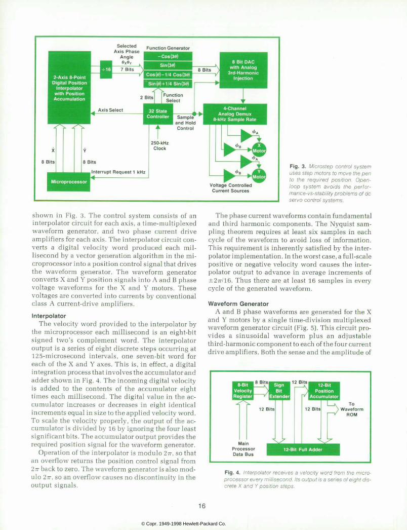
shown in Fig. 3. The control system consists of an interpolator circuit for each axis, a time-multiplexed waveform generator, and two phase current drive amplifiers for each axis. The interpolator circuit con verts a digital velocity word produced each mil lisecond by a vector generation algorithm in the mi croprocessor into a position control signal that drives the waveform generator. The waveform generator converts X and Y position signals into A and B phase voltage waveforms for the X and Y motors. These voltages are converted into currents by conventional class A current-drive amplifiers.
Interpolator The velocity word provided to the interpolator by
the microprocessor each millisecond is an eight-bit signed two's complement word. The interpolator output is a series of eight discrete steps occurring at 125-microsecond intervals, one seven-bit word for each of the X and Y axes. This is, in effect, a digital integration process that involves the accumulator and adder shown in Fig. 4. The incoming digital velocity is added to the contents of the accumulator eight times each millisecond. The digital value in the ac cumulator increases or decreases in eight identical increments equal in size to the applied velocity word. To scale the velocity properly, the output of the ac cumulator is divided by 16 by ignoring the four least significant bits. The accumulator output provides the required position signal for the waveform generator.
Operation of the interpolator is modulo 2rr, so that an overflow returns the position control signal from 2?7 back to zero. The waveform generator is also mod ulo 277, so an overflow causes no discontinuity in the output signals.
The phase current waveforms contain fundamental and third harmonic components. The Nyquist sam pling theorem requires at least six samples in each cycle of the waveform to avoid loss of information. This requirement is inherently satisfied by the inter polator implementation. In the worst case, a full-scale positive or negative velocity word causes the inter polator output to advance in average increments of ±277/16. Thus there are at least 16 samples in every cycle of the generated waveform.
Waveform Genera tor A and B phase waveforms are generated for the X
and Y motors by a single time-division multiplexed waveform generator circuit (Fig. 5). This circuit pro vides a sinusoidal waveform plus an adjustable third-harmonic component to each of the four current drive amplifiers. Both the sense and the amplitude of
8-Bit Velocity Register
8 Bits Sign Bit
Extender
12 Bits
12 Bits
Main Processor Data Bus
12-Bit Position
Accumulator
12 Bits I K T o
y W a v e f o r m V R O M
12-Bi t Ful l Adder
Fig . 4 . In te rpo la to r rece ives a ve loc i t y word f rom the mic ro processor every mi l l isecond. I ts output is a ser ies of e ight dis crete X and Y pos i t ion s teps.
16
© Copr. 1949-1998 Hewlett-Packard Co.

Motor Phase Angle 6 (7 Bits)
Outputs to X-Axis Motor
Drivers
State Control ler for Waveform Selection and
Control of S1-S6
S & H = S a m p l e a n d H o l d
To Sample and Hold Circuits
# 3 a n d # 4
F i g . 5 . W a v e f o r m g e n e r a t o r p r o duces A and B phase wave fo rms for the X and Y motors . An ad jus t ab le th i rd-harmonic component is added to prov ide smoothness and precis ion not previously at tainable wi th step motors.
the third harmonic can be set independently for each axis.
X and Y position data words from the interpolator are time-multiplexed together to form the least sig nificant bits of the nine-bit ROM address. The two most significant address bits are set by a state control ROM to define which of the four parcels in the waveform ROM is addressed. The four ROM parcels are the A phase third harmonic, the A phase funda mental plus third harmonic, the B phase third har monic, and the B phase fundamental plus third har monic. Each of these parcels consists of 128 eight-bit words.
At the beginning of a period, the X position is present in the ROM address, analog switch S2 is closed, and S3 is open. The two high address bits are set so that the A phase third harmonic is addressed. After the digital-to-analog converter (DAG) has had time to settle, Si is closed long enough to load the third harmonic sample into sample-and-hold circuit number 5.
Next, the high address bits are changed to access the parcel containing the A phase fundamental plus third harmonic. At this time Si is open and S4 is closed. Once the DAC has settled, the output of the summing amplifier consists of the A phase funda mental and an adjusted amount of third harmonic. The adjustable third harmonic level added to the waveform through S2 is out of phase with that pre loaded into ROM parcel 2 so that the resultant level is adjustable from negative through zero to positive. After the A phase waveform has settled, S5 is closed to set sample-and-hold circuit number 1. The output
of this circuit is a stairstep approximation of the de sired continuous current waveform. Post-sample fil tering smooths this signal into its final form.
The B phase waveform is generated similarly by first addressing the B phase third harmonic parcel and loading sample-and-hold circuit number 5. The B phase fundamental plus third harmonic is then added to the adjusted third harmonic component to produce the B phase waveform. S6 is closed momentarily to set sample-and-hold circuit number 2. The action to this point is completed in the first half of the 125-mi- crosecond period.
During the second half of the period, S2 is open, S3 is closed, and the seven-bit Y position word is con nected to the lower part of the ROM address bus. Waveforms are constructed in the same manner as before except with adjustment provided by R2. Stairstep approximations of the Y-axis phase current waveforms appear at the outputs of sample-and-hold circuits number 3 and 4.
Control of the two data control bits, the multi plexer, and the eight analog switches is provided by a state control ROM not shown in Fig. 5. This ROM is addressed by a state counter driven by the system clock. The bit pattern programmed into this ROM establishes the sequence of operation described above.
Control ler Adjustment Four adjustments are provided for each axis of the
control system to allow its performance to be op timized for the actual operating environment.3 First, dc offset can be adjusted in both phase current drive
1 7
© Copr. 1949-1998 Hewlett-Packard Co.

amplifiers. Next, each B phase current amplifier pro vides a vernier gain adjustment that allows equaliza tion of the magnetomotive force developed by the A and B phase currents. Finally, a single adjustment for each axis sets the level of third harmonic in the phase current wave form. This minimizes the level of fourth harmonic torque developed by each motor. An inter nal self-test feature aids in the adjustment of these controls.
Plot ter Performance The mechanical linkage in each axis connecting the
motor shaft to the pen tip causes 0.25 mm (0.01 inch) of motion for each motor step. Each cycle of the waveform generator advances the rotor by the angular pitch of one rotor tooth, the equivalent of four steps. Thus the pen moves one millimetre for each cycle out of the waveform generator. There are 128 increments in the address to the ROM in the waveform generator, so each increment is equivalent to 0.008 mm (0.0003 inches). The maximum magnitude of the velocity word produced by the vector generator algorithm is 90 binary units, which causes the ROM address to advance by 45 counts each millisecond. This pro duces a maximum axial velocity at the pen of about 360 mm/s.
The vector generator algorithm in the microproces sor accepts movement commands to a resolution of 0.001 inch or 0.025 mm, which is approximately three times greater than the minimum control system in crement. The algorithm converts these move com mands into X and Y velocity profiles that accomplish the required move. The maximum velocity attained in a long move by either axis can be varied under user program control in 10-mm/s increments from a minimum of 10 mm/s to the maximum value of 360 mm/s. This allows the user to optimize the pen speed and associated writing quality for any given drawing media. The maximum axial acceleration established in the velocity profiles is about 4000 mm/s2 (160 in/s2) or 0.4 g. When the user has programmed a lower than maximum velocity, however, the algorithm assumes that line quality is more important than speed. The acceleration is then halved to further eliminate any minute acceleration transients from the drawn vec tors.
Acknowledgments The mechanical characterization with the resultant
inertial matching and mechanical damping was de veloped by Majid Azmoon and George Lynch. George Lynch also designed much of the Y axis arm. Steve White developed the voltage controlled current source motor drivers. SS
References 1. P.J. Lawrenson and I.E. Kingham, "Low Frequency
Resonances", Proceedings of the International Conference on Stepping Motors and Systems, University of Leeds, England, 15-18 July 1974. 2. G. Sigh, A.C. Leenhouts, and E.F. Mosel, "Electromagnet Resonance in Permanent Magnet Step Motors", Fifth Annual Symposium on Incremental Motion Control Systems and Devices, B.C. Kuo, Editor; University of Illinois, 1976. 3. M.L. Patterson, "Analysis and Correction of Torque Harmonics in Permanent Magnet Step Motors", Sixth Annual Symposium on Incremental Motion Control Systems and Devices; B.C. Kuo, Editor; University of Illinois, 1977. 4. M.L. Patterson and R.D. Haselby, "A Microstepped X-Y Controller with Adjustable Phase Current Waveforms"; Sixth Annual Symposium on Incremental Motion Control Systems and Devices; B.C. Kuo, Editor; University of Illinois, 1977.
Robert D. Haselby Bob Hase lby deve loped the 9872A/7221A's motor dr ive s ignal generat ion c i rcu i t ry and the 7221 A's RS232C interface hardware and f i rmware. He 's the co-author (with Marv Patterson) of a paper on microstep contro l . Bob grew up on a farm in Indiana. After s i x years in the U.S . Navy Sub marine Service, he returned to his
' home s ta te t o a t t end Pu rdue Un i - x ' S ve rs i t y , rece i v ing h i s BSEE degree
1 i n 1972 and h i s MSEE deg ree i n x I 1 973 . He s t i l l goes to sea , bu t now
* i t ' s fo r fun , on a sa i lboat . Bob and h is wi fe and son l ive in Escondido, Cal i forn ia .
R i c h a r d M . K e m p l i n D ick Kemp l in has been a d ra f t sman and p roduc t des igner w i th HP for 23 years . He he lped deve lop the pen changer , m e c h a n i c a l d r i v e , a n d d e c k d e sign of the 9872A/7221A Plot ters. He 's l i s ted as inventor in f i ve pa tents on X-Y recorder mechanica l des ign . D ick was born in G len- da le , Cal i forn ia . He rece ived an AA degree from John Muir Col lege in 1 952, then spent two years in the U.S. Army Corps of Engineers be fore jo in ing HP in 1954. He 's mar r ied, has four ch i ldren ranging in
age from 9 to 21, lives in Poway, California, and is half owner of a Commanche 250 a i rc ra f t , wh ich he f l ies whenever he can.
18
© Copr. 1949-1998 Hewlett-Packard Co.

APPENDIX Correct ion of Non- Ideal Step Motor Behavior
The mo to r s used i n t he 9872A and 7221 A P lo t t e r s a re f ou r -phase pe rmanen t magnet in motors w i th 200 s teps per revo lu t ion . Phases 1 and 3 are connected in se r i es , as a re phases 2 and 4 , so t he mo to r appea rs ex te rna l l y as a two -phase inductor- type synchronous motor. Torque is developed independent ly by each phase in the conf igurat ion and is g iven by^
EQA'A TA =
TB = E g B ' B
where u by the angular velocity of the rotor, Eg^ and Egg are the voltages induced by the permanent magnet in the two phase windings, and l^ and Ig are the appl ied phase currents . When the rotor ve loc i ty is constant the torque produced by each phase is s i m p l y t h e p r o d u c t o f t w o t i m e - p e r i o d i c w a v e s . T h e w a v e f o r m s o f E g ^ a n d E g g vary geometry the particular motor and depend primarily on the air-gap geometry between the stator poles and the rotor . The appl ied phase current waveforms are speci f iable and can be ad justed to improve the smoothness of the motor operat ion.
- 6 0
- 7 0
1 I 5 0 1 0 0 2 5 0 1 5 0 2 0 0
Frequency (Hz)
Fig . 1 . Spec t rum o f t yp ica l s tep motor genera ted vo l tage wavefo rm.
Uncorrected Corrected
Fig. fundamental interacting torque results from phase current fundamental interacting wi th th i rd and f i f th motor harmonics. To reduce this ef fect , th i rd harmonic is added to the phase currents.
ages phase at each stator pole to re inforce at the external phase terminals . On the o ther hand, the even harmonics wi l l , idea l ly , cance l . Th is c reates the pecu l ia r odd harmonic nature seen in the spect rum shown.
At constant rotor velocity the spectrum of the torque produced by the A phase stator poles can be found by convolving the spectrum of Eg^ with that of l^. This convolution i s s h o w n g r a p h i c a l l y i n F i g . 2 f o r l ^ e q u a l t o a c o s i n e w a v e a t t h e f u n d a m e n t a l frequency of E g^. The result ing torque spectrum is as shown, with a major component a t dc and other non- ideal terms at the even harmonic f requencies.
The total shaft torque of the motor is the sum of the A and B phase contributions. In a proper ly dr iven, symmetr ic motor the B phase torque waveform is ident ical to that of the A phase except for a one-fourth-period delay. When the two torque waveforms add at the t imes th is de lay causes the torque harmonics at 2 , 6 , 10, . . . t imes the phase current frequency to cancel exact ly. The torques produced at dc and the 4th, 8th, . . . harmonics reinforce exact ly. Since only dc torque is desired to keep the rotor moving smoothly at constant velocity, the higher harmonic terms represent non-ideal effects in the motor tha t tend to per tu rb the ro to r ve loc i ty . When the f requency o f these har mon ics the on a mechan ica l resonance, exaggera ted osc i l la t ions can occur in the rotor motion.
The dominant non- ideal torque component is typ ica l ly the four th-harmonic terms. Reference 3 shows that the magnitude of this component can be signif icantly reduced by adding a third-harmonic component to the waveform of the A and B phase currents. F i g . 3 cu r ren t how the f ou r th -ha rmon i c t o rque i s t he resu l t o f t he phase cu r ren t fundamental interacting with both the third and fifth harmonics in the motor spectrum. A proper ly adjusted th i rd harmonic in the current waveform wi l l in teract wi th the funda mental voltage from the motor to produce a corrective fourth-harmonic torque term that s igni f icant ly reduces the magni tude of the resul tant non- ideal torque.
E9A«">
T_8T_6 I A T 6 T Â ° \ * *
- 8 c u n - 2 w 0 0 8o>0
F ig . t o rque A o f cu r ren t and vo l t age wave fo rms p roduces t o rque spec t rum o f t he A phase s ta to r po les . Ma jo r t o rque com ponent Typically at dc. There are non-ideal terms at even-harmonic frequencies. Typically the fourth-harmonic terms dominate.
Ins ight in to the non- idea l behav ior o f the motor can be ga ined by examin ing the nature voltages the characteristic motor waveform apparent in the open-circuit voltages Eg^ and Egg when the ro to r i s tu rned a t cons tan t ve loc i ty . An idea l motor under these condit ions would produce sinusoidal voltage waveforms. In contrast, the spectrum of a typical generated waveform is shown in Fig. 1. The interconnect ion of internal stator windings to form an external two-phase conf igurat ion causes the odd harmonic vol t -
The microstep control ler used in both the 9872A and 7221 A digital plotters provides an adjustable third-harmonic component in the phase current waveforms. This al lows the smoothness of p lo t ter operat ion to be opt imized for each ind iv idual motor , thus prov id ing uni form l ine qual i ty f rom one machine to the next .
•Marvin Patterson
19
© Copr. 1949-1998 Hewlett-Packard Co.

Pen and Ink System Helps Assure Four-Color Plotter Line Quality by Leonard P . Ba lazer , George W. Lynch , R ichard M. Kempl in , and Lar ry W. Hennessee
PENS FOR THE NEW FOUR-COLOR PLOTTERS have been carefully designed to contribute to the
plotters' high-quality, precisely defined, and aesthet ically pleasing graphical presentation, a presentation that, directly from the plotter, can enhance en gineering reports, proposals, and other critical com munication documents. In pursuit of this goal the individual properties of a high-quality graphical presentation were first dissected, defined, and cata loged. Desirable qualities, such as appropriate line width, line width uniformity, color density, line registration, and absence of feathering or bleeding became the design objectives for the pen and ink system.
Although the automatic pen changing concept in troduced formidable new problems of dimensional control concerned with line registration, the first order of priority was to attack problems that have always haunted the disposable pen. Of these, line width control and line width uniformity are the most difficult. The writing tip tends to flatten and produce an excessively wide line under the influence of the impact forces generated when the pen is dropped onto the platen. These forces, together with the flat tening effects of abrasive wear as the pen scrubs across the paper, can cause line width to grow from an initial 0.13 mm to 1 mm or more after writing several meters. Not only does this produce an obvious dispar ity in line widths as a new pen deteriorates, but also the line can become so wide that it masks information details and closes the loops in small text characters. Another line control problem is seen at high writing speeds, where a pen may fail to produce a dense, easily discernible trace.
Of the several possible ways of drawing a line, such as the capillary pen, the ball point pen, the pencil, and so on, the disposable fiber tip pen was selected as having the greatest potential for meeting all require ments. The ball point pen required too much force against the paper and did not start well. The capillary pen was messy and often lost its prime. Extruded plastic tips did not deliver a sufficient ink flow at high speeds and often developed a wear flash that shut off the ink ducts.
The Nib Of all the elements of a disposable fiber tip pen, the
nib and the ink are the two most important. The first
question we addressed was whether to make or buy the nib.
The alternative of making our own nib, a subject we knew nothing about and had no equipment for, was relegated to last place among the various ways of proceeding. Another alternative was to buy and use a modification of an existing instrument or handwrit ing pen made by another manufacturer. However, no suitable pen could be found. The search was not su perficial and involved pens ordered from every man ufacturer in the world who somehow managed to make his existence known through advertisements, listings, or references. Some 50 different pens were evaluated and rejected.
It turned out that at least seven manufacturers of fiber nibs exist in the world and each makes several varieties of nibs. All supplied us with samples. The samples were evaluated according to criteria impor tant to us and graded relative to one another. We quickly realized that the most serious general nib problem is uniformity. After extensive investigation into the processes of nib making, we also realized that fiber nib making is more an art than a science , and that the makers of good nibs know very little more why their nibs are good than the makers of poor nibs know why their nibs are bad (careful production control, of course, being an obvious factor). Fortunately, one nib was found to be quite good. The manufacturer of this
Ink Reserve-
Paper Surface
Fiber Reservoir
Ink Meniscus
Fig . 1 . Hydrau l ic sys tem of a pen. The meniscus is the in ter lace be tween the ink reservo i r and the paper .
2 0
© Copr. 1949-1998 Hewlett-Packard Co.

nib was unusually cooperative and a series of detailed evaluations of this product was begun.
Since the primary concern was uniformity, four separate nib orders were placed in successive months, and a production sample from ten successive days was obtained. Uniformity was found to be excel lent. Thereafter, several iterations in point and shank shape and size were completed and thus the 9872A pen nib was selected. It took two years.
Ink Fig. 1 shows the hydraulic system of a pen, and the
meniscus around the pen tip. As soon as the pen nib touches the paper surface, the annular wedge-shaped interface pulls out ink into this space and the ink sticks and stays in place as the nib moves on, leaving a discernible line.
The nib consists of a loose pack of continuous lon gitudinal nylon fibers about 0.03 mm in diameter, held together with resin to form an irregular matrix of longitudinal ducts. A cross section of a nib is shown in Fig. 2. As the packing of the fibers becomes more dense, the nib becomes physically stronger, but the interstices through which the ink flows become smal ler. Thus as the nib becomes stronger and denser and more able to retain a sharp point while being pounded on the writing platen, the ink flow becomes more restricted. High nib density, of course, also decreases the rate of abrasive wear as the pen is dragged across the paper, and is a desirable characteristic for all considerations except ink flow. Therefore, the design approach was to make the nib as dense as possible compatible with a sufficient ink flow. The way to increase ink flow with a given duct size, in turn, is to decrease its viscosity, so one primary ink requirement
Fig. 2. Cross-sect ion of a n ib, showing f ibers and in terst ices th rough wh ich ink f l ows . N ib des ign requ i res a t rade-o f f be tween c lose pack ing o f the f ibers , wh ich a ids durab i l i t y , and good ink f low.
is low viscosity. What other characteristics ought a plotting pen ink
to have? For one, it must not dry out in the uncovered pen tip too rapidly. The design standard is that the pen should start to write immediately on contact with the paper after having its cap off for up to three days in normal laboratory atmospheres. Hence low volatility is desirable. Fortunately, this property usually comes with high surface tension, which is the source of the force that pulls the ink out of the pen onto the paper.
The ink must wet the paper to form the meniscus and to stay there after the pen has moved on, but it must not wet too well. If it wets too well, the ink-to- paper lateral interface becomes ragged and irregular. This is often called feathering, since tiny feather-like structures sometimes form. When the pen is left stationary against the paper and an ever-growing blob appears around the tip, it is called bleeding.
If the ink does not wet the paper well enough it will tend to form into little balls after the pen moves on. The ideal ink is neutral: it will not spread or retract. The 98 72 A inks very nearly possess this characteris tic on HP graph paper. You can leave the pen on the paper as long as you please, just so it isn't on a finger print. This neutrality is responsible for the new plot ters' definite and regular ink-to-paper interface that produces the appearance of crispness and cleanness.
Besides having definite paper-wetting characteris tics, the ink must enter into a chemical combination with the paper fibers that can be classified as a com plicated kind of adsorption. Evaporation is unsuita ble as a fixing mechanism since evaporation also takes place in the pen nib and reduces cap-off drying time to unacceptably short periods. Ink that is fixed by evaporation also has the messy tendency to smear under damp finger tips.
Other necessary ink characteristics are color den sity and stability. Ink dyes are usually organic molecules that deteriorate with time. The period until a definite fading or color change becomes manifest must be at least two years for normal distribution and use. (Printer's black ink does not contain a dye, but lampblack, which lasts forever.) The ink must also be compatible with the nib material as well as the pen structure and not cause swelling, crazing, or stress cracking. Finally, the ink must be retainable, that is, it must not escape through the pen body at an excessive rate.
The 9872A inks were compounded through com plicated trade-offs involving all of the above- mentioned factors.
Pen Structure In the world of fiber tip pens, the 9872A pens have
the distinction of being dimensionally precise beyond all others. Lack of dimensional precision is in
21
© Copr. 1949-1998 Hewlett-Packard Co.

V e n t T u b e
Plug
Fi l ler (with Vent Tube)
Body
Cao
F ig . 3 . Pen s t ruc tu re i s des igned to p reven t l eak ing a t a l t i tudes up to 50,000 feet .
no way detrimental, for example, to a handwriting instrument. It does not matter one jot if the pen barrel is bowed, or out of round, or eccentric by 0.1 or 0.2 mm. However the 9872A multiple-pen concept and the requirement for exact line registration imposes the need for a hitherto unknown (to HP, at least] level of mechanical precision in the pen.
Fig. 3 depicts the structure of this pen. The bottom of the flange and cylindrical surface "A" are the inter face surfaces that control pen position and have to be maintained round, flat, square, and the same size. This requirement eliminated all but the lowest- shrinkage plastic molding compounds. (The alterna tive of machining these surfaces was rejected on the basis of its high cost.) This also imposes the restric tion that these surfaces had to be molded within a single continuous-mold cavity, eliminating alternate designs involving split cavities and side pulls. The four cavities of the four-part mold had to be matched with extreme care beyond the normally high level of moldmaking precision. Also, molding process parameters have to be very carefully controlled to produce well-matched parts.
The pen venting scheme can also be seen in Fig. 3. As an external vent, the round nib fits into a square hole, and the unfilled corners allow air to flow into and out of the interior of the pen. A plastic tube continues the venting from the lower to the upper interior cavity. Without such venting, pressure or temperature changes that cause the air inside the pen to expand would cause ink to be forced out of the pen, producing dreaded leaking. This scheme works well for ordinary handling at ordinary pressures; however,
Digitizing Sight Adds Versatility T h e 9 8 7 2 A / 7 2 2 1 A P l o t t e r ' s e l e c t r o n i c p e n - p o s i t i o n i n g c i r
cui try incorporates a digi t iz ing capabi l i ty, that is, i t can digi tal ly measure an arb i t rary pen pos i t ion. This is very usefu l in many data process ing and record ing appl icat ions. Unfor tunate ly , an ink pen is a poor cursor or ind ica tor o f pen car r iage pos i t ion , because judg ing the p rec ise loca t ion o f the pen i s a d i f f i cu l t mat ter , sub jec t to para l lax and confus ion by shadows.
A d ig i t i z ing s igh t was deve loped to fac i l i t a te the d ig i t i z ing process by making i t easier to posi t ion the pen carr iage and by vas t l y improv ing the accu racy o f t he p rocess . The d ig i t i z i ng s i gh t i s a l so use fu l i n se t t i ng t he r eg i s t r a t i on o f t he pen on p re - l i ned g raph pape r o r on ma te r i a l p rev ious l y w r i t t en and removed and la ter rep laced on the p lo t ter p la ten.
The digit izing sight is a passive optical device much the same s ize and shape as the pen (see photograph) .
The d ig i t i z ing s ight br ings the ¡mage o f a po in t o f in teres t together w i th a super imposed re fe rence po in t on an e leva ted p lane where i t can be v iewed f rom wi th in a 70° cone wi thout parallax effects. The brightness of the ¡mage ¡soften enhanced, since ¡mage brightness does not depend on the i l luminat ion at the platen surface, but on the i l luminat ion at the top surface of the s ight , wh ich is f ree o f shadows f rom the pen car r iage.
How does the d ig i t i z ing s igh t work? Bas ica l ly the s igh t con s is ts o f a coherent bundle o f opt ica l f ibers , each of which con duc ts l i gh t ga the red a t i t s upper su r face down to the wr i t i ng surface it rests upon. The l ight reflected from the writ ing surface is conducted back through the f iber to the upper surface, where i t is spat ia l to the observer 's eye. Each f iber reta ins i ts spat ia l relat ionships to i ts neighbors at the upper and lower surfaces so the combined effect of all the fibers is to transmit the image of the mater ia l over which the bundle is p laced.
Any desired reference marks or ret ic les can simply be placed on e i ther the upper or lower sur face. The d ig i t iz ing s ight has a s ingle spot about 0.5 mm in diameter at i ts center. A point spot was chosen s ince the s ight in ter faces wi th the pen ho lder and the s tab le i n t he same way as a pen and can be se lec ted o r stored in the same manner as a pen. In the transfer process from stable to holder and back, the pen rotates through an arbi t rary angle . I f c rosshai rs had been used on the s ight they would be del ivered at arbi t rary angles and so were rejected as reference marks.
In use, the reference point in the digi t iz ing sight must exact ly dup l i ca te pen t i p pos i t i on ; t he re fo re , a l t hough the d ig i t i z i ng s igh t i s a very s imp le dev ice , the d imens ions o f the in te r face surfaces and the locat ion of the reference point are cr i t ical and are careful ly control led.
-Leonard Ba lazer
2 2
© Copr. 1949-1998 Hewlett-Packard Co.

at altitudes above about 45,000 feet, the ink begins to outgas, although it does not boil. This produces a foam that can be pushed out of the pen by further gas expansion. This happens especially in sudden de compressions, such as when the cap or plug is blown off the pen by internal pressure. To prevent this sort of thing, the plug and the cap are equipped with smooth sealing surfaces and assembled to the body with inter ference fits, so the pen retains normal atmospheric pressure internally for extensive periods at altitudes beyond 50,000 feet without popping off its plug or cap.
When the cap is forced over the nib end of the pen, the pen is tightly sealed, preventing slow evaporative ink loss. This sealing is sufficient for several months at ordinary laboratory environments. However, the water component of the ink escapes through the pen body walls, so for long-term storage, the pens are hermetically sealed in foil pouches that effectively prevent any measurable moisture loss.
Pen Stab le and Pen Changer The pen changing mechanism is perhaps the most
interesting mechanical aspect of the 9872A from the user's standpoint. During many demonstrations ob servers have marveled at the speed with which the instrument changes pens and trace colors.
To minimize its mass, the carriage holds only one pen at a time. An alternative might have been to transport a rotating turret with all the pens on the
carriage, but this would have substantially increased the response time of the machine. Instead, all the pens are stored in a four-position "stable", where they are kept capped to prevent them from drying out in arid climates (Fig. 4). When a pen is selected no active elements (e.g., solenoids or motors) are used to effect the change. A ramped surface on the nose of the pen carriage simply drives down a spring-loaded bracket that carries a pen cap away from the tip of the pen. When the pen is removed by the carriage the bracket springs back into its original position. The same spring that returns the bracket also retains the bracket in the stable, so assembly is rapid and simple.
No expensive active elements are used to hold the pens in the stable or carriage. Carefully balanced spring-loaded arms support the pens and the special digitizing sight (see box at left) in both the stable and the carriage. The upper and lower arms that sup port each pen are identical, as are their return springs and mounting hardware. This helps keep the overall cost of the stable so low that an early plan to offer the stable as a moderately expensive option was dropped.
While the simplicity of the stable precludes the need for much service, the opportunity to provide occasional repair is readily available. A few accessi ble screws allow the entire control panel to be re moved and two screws are removed to expose virtu ally the entire stable mechanism.
The motions used by the plotter to fetch or store pens are ordinary X and Y moves of the arm. The
F i g . 4 . F o u r - p o s i t i o n p e n s t a b l e holds pens of var ious colors when they are no t in use . (F i l th s ta l l i s used to determine whether there is a p e n i n t h e c a r r i a g e . ) U n u s e d pens a re kep t capped t o p reven t i n k d r y i n g . T o c h a n g e p e n s , t h e p e n c a r r i a g e s t o r e s t h e c u r r e n t p e n i n a n e m p t y s t a l l a n d t h e n p i c k s u p t h e n e w p e n u s i n g o r d i nary X and Y mot ions.
2 3
© Copr. 1949-1998 Hewlett-Packard Co.

patterns for fetching or storing from or to each stable position (stall) are stored in read-only memory (ROM) along with the firmware pen-changing algorithm that moves the arm in these patterns to execute the re quested pen change.
Pen change requests are initiated under program control via the input/output system or locally from the plotter's front panel. Requests for a pen from a vacant stall are ignored. Should all four stalls and the arm contain pens, all pen change requests are ignored because the arm must be vacant before it can fetch a pen from the stable.
For the pen-changing algorithm to make such deci sions it must be able to detect the occupancy status of each stall and the arm. Each stall is equipped with a microswitch to indicate the presence or absence of a pen. Another microswitch, in a fifth stall not used for pens, detects the occupancy status of the arm. These five microswitches enable the algorithm to avoid fetching a pen from an empty stall or storing a pen into an occupied stall.
Should the plotter be requested to fetch a pen from an occupied stall and there are one or more vacant stalls, the algorithm assumes the arm has a pen, and moves the arm in the pattern necessary to store the pen into an empty stall. If there is more than one vacant stall, the algorithm returns the pen to the stall from which it was originally fetched, unless that stall is no longer vacant (perhaps someone has hand- loaded it), in which case the lowest-numbered vacant stall is selected to receive the pen. After executing the pattern to store the arm's current pen, if any, into a vacant stall the algorithm executes the pattern to fetch the requested pen.
If the plotter is requested to fetch a pen when all
Solenoid
Precision Bearing Pivots
F i g . 5 . P e n l i f t m e c h a n i s m o f t h e f o u r - c o l o r p l o t t e r . P n e u mat i c dashpo t con t ro l s impac t ve loc i t y so the pen t i p i s no t deformed, there is no ink b lob when the pen is dropped, and the pen does no t bounce .
Fig. 6. Trail ing cable provides power to the pen l i f t assembly .
four stalls are occupied, the fifth "pen-in-arm" mi croswitch is used. The arm must be vacant before it can receive a pen from the stable. The algorithm moves the arm to the fifth microswitch, and if the arm is vacant, the pattern to fetch the requested pen is executed. If the arm contains a pen, the pen change request is ignored because there is no vacant stall to receive the current pen before fetching the requested one.
The move pattern to store a pen into a stable is the reverse of the pattern to fetch a pen from that stable. After a pen change, the algorithm returns the arm to its platen position before the pen change request.
Pen Li f t Mechanism Design objectives for the pen lift mechanism for the
new four-color plotters included reliable operation and lifetime at least an order of magnitude longer than earlier designs. The life target was set initially at 40 million cycles of operation without any mainte nance or service.
When the mechanism lowers the pen it must not slam the pen into the hard platen and smash the pen tip. Once the pen is down and slewing across the paper, the mechanism must hold the pen rigidly or it will chatter and skip, leaving a dotted line.
Before the plotter can begin to draw a line segment, it must pause long enough to lower the pen. The speed with which the plotter can draw such figures as characters or dashed lines depends heavily upon the length of this delay. The new mechanism had to minimize this pen-down delay.
In addition to these objectives, several require ments were imposed by new features designed into the 9872A. With the introduction of the pen stable, the pen holder had to be able to reach off the drawing surface to drop off or pick up a new pen quickly and
2 4
© Copr. 1949-1998 Hewlett-Packard Co.

with 100% reliability. Since the prime movers of the plotter are open-loop stepper motors and have no position feedback, it is possible to overpower the mechanism and displace the arm and pen carriage in such a way that the pen holder crashes into the front panel at full slew speed and with full motor power when reaching for a new pen. The pen l if t ing mechanism had to be designed to withstand this kind of crash. In the worst-case collision the impact is to the slender lever that clutches the pen.
The pen lift mechanism of the 9872A and 7221A Plotters is shown in Fig. 5. Underneath the pen lift cover is a pneumatic dashpot that helps achieve sev eral of the objectives. The damping rate of the dashpot can be adjusted in the plotter so the pen impacts the table at a rate of about two inches per second. At this velocity the impact with the table top can be easily absorbed by elastic deformation of the pen tip. This prevents mushrooming of the pen tip after successive pen drops so effectively that now the only reason for a pen to become unserviceable is that it runs out of ink. At low impact velocity there is no ink blob where the pen is dropped and the tendency for the pen to bounce upon impact is reduced, permitting a shorter pen-down delay and a faster character plotting speed.
The two major structural pieces of the pen lift as sembly are aluminum die castings. They provide compactness, the rigidity to keep the pen from chat tering while drawing high-speed vectors, and the strength to withstand impacts into the front panel and pen stable.
Several different high-strength materials were tested for the lever that grips the pen. Most broke upon impact with the corner of the front panel when reaching for a new pen after the arm had been forced out of position. It turned out that a common acetal resin produced an injection-molded lever that was durable enough to withstand repeated worst-case im pacts and had the creep resistance to stand up to the stresses produced by the pen gripping spring.
Precision bearings are used in the hinge of the lift ing mechanism for smooth operation over a long ser vice life. Life tests were discontinued after 40 million lift-drop cycles with little noticeable wear to critical parts.
Putting the pen-lift solenoid close to the pen re duced the audible noise to a tolerable level and im proved overall reliability by minimizing wear and the number of moving parts. It did, however, necessitate development of a trailing cable inside the slender arm. A thin, twin-lead flexible circuit met the flex-life requirements, but pushing that circuit in the return direction into the slender arm was like trying to push a chain by one end; the tangles that resulted were disastrous. Supporting the flexible circuit on each side with a crowned, stainless steel strip provided the
stiffness necessary to control it. The effect is similar to bending a steel tape measure: the straight portion is stiff while bending stresses are kept low in the looped portion. Fig. 6 shows the trailing cable assembly in side the arm.
The pen lift assembly is easy to assemble and ser vice. The three adjustments (pen height, pen force, and damping rate) are accessible from the top after removing one screw and the pen lift cover (Fig. 5). The interior of the arm, shown in Fig. 6, can be ex posed by removing one more screw and snapping off the arm cover.
Acknowledgments Immeasurable credit is due Rick Tverdock for
coordinating the design and working out the details to make sure that the pen holder comes out of the stable with a pen in hand every time. Dave Perach successfully completed the difficult job of conceiving the initial design of the pen lift mechanism. ¿?
George W. Lynch George Lynch received his BSME degree in 1971 f rom Ok lahoma Sta te Un ivers i t y and h is MS de gree in aerospace eng ineer ing in 1973 from Cal i fornia Inst i tute of Technology. He jo ined HPin 1972, and deve loped the pen l i f t mechanism and mechanica l dr ive sys tem o f the 9872A and 7221A Plot ters. Born in Borger, Texas, he 's mar r ied and l i ves in Escon d ido, Cal i forn ia. Before a recent vaca t ion in Hawa i i , George oc cupied his .spare time with golf, ski ing, and rad io-cont ro l led g l iders
and cars. Now he has a new passion — surf ing.
\
Leonard P . Baiazer Leonard Ba iazer rece ived h is BS degree in phys ics f rom Mich igan State Univers i ty in 1954 and h is MS in automot ive engineer ing f rom Chrysler Inst i tute in 1957. Wi th HP s ince 1972, he 's been in vo lved w i th g raph ic recorder mechanism and pen des ign. Born in Ch icago, Leonard spent two years in the U.S. Army before en ro l l ing at Michigan State. Before com ing t o HP , he se rved f o r sev era l years as a program manager in the aerospace indust ry , au thor ing two successfu l patent appl ica
tions he airborne ranging. Now living in San Diego, California, he devotes much of his t ime to sculpture and the study of language. He has three co l lege-age ch i ld ren.
2 5
© Copr. 1949-1998 Hewlett-Packard Co.

A Bat tery -Powered ECG Moni tor for Emergency and Opera t ing Room Environments Elect r ica l iso la t ion, reduced suscept ib i l i ty to RF and e/ect rosurgery in ter ference, and bat tery power equ ip th is non-fade ECG monitor to operate in the electr ical ly host i le env i ronments found in emergency veh ic les and opera t ing rooms.
by Sherry R . Grobste in and Ronald D. Gatzke
CONTINUOUS MONITORING of a patient's ECG provides one of the important indicators of a
patient's physiological status when in surgery or when being transported in an emergency vehicle. It follows, then, that ECG monitoring instruments must be depended on to operate continuously under these circumstances.
This does not always happen. Emergency envi ronments are far more hostile to a monitoring instru ment than the usual hospital ward and therefore im pose special requirements. For example, the transmit ters used by emergency vehicles generate RF interfer
ence that is much stronger than any encountered in the hospital. Hence, a monitor for emergency vehicle use must be highly immune to RF interference, as well as being more rugged than those designed for fixed-installation service.
In the operating room, very strong interference is generated by electrosurgical machines, causing the usual ECG monitor to be useless during certain pro cedures. The operating room also imposes severe re quirements on electrical safety. With the amount of electrical equipment involved — fluid pumps, motor ized operating table, electrosurgical equipment —
Fig . 1 . Mode l 78333 A ECG Mon i t o r d i s p l a y s E C G w a v e f o r m a n d h e a r t r a t e w i t h m i n i m u m i n t e r f e r e n c e f r o m e l e c t r o s u r g e r y e q u i p m e n t o r o t h e r s o u r c e s o f e l e c t r o m a g n e t i c r a d i a t i o n . I n t e r n a l r e c h a r g a b l e b a t t e r i e s c a n power the inst rument for up to s ix hours.
2 6
© Copr. 1949-1998 Hewlett-Packard Co.

the chances of accidents from improperly grounded equipment are increased. At the same time, the patient's primary protection against electrical shock, the skin, is breached.
Dependable Moni tors The growing need for EGG monitors that can oper
ate safely and reliably in these more difficult envi ronments has led to the development of a new EGG monitor, Hewlett-Packard Model 78333A (Fig. 1). This instrument is rugged enough for mobile use and it is battery-powered for portability. It also incorpo rates other features that minimize some of the electri cal hazards peculiar to battery-powered instruments (see box at right), and it is highly resistant to RF interference.
The new monitor presents a single EGG waveform on a non-fading CRT display along with a horizontal bar graph that indicates heart rate. In addition to the visual display, it gives an aural indication by means of a "beeper" that makes attending medical personnel aware of cardiac events without requiring them to watch the CRT. It beeps in response to each R wave and variations in the pitch provide an indication of arrhythmias, giving immediate warning of trouble. A steady tone in the beeper indicates an INOP (inopera tive) condition. Adjustable heart-rate alarm limits are indicated visually on the bar graph and audibly by the beeper, which generates a steady tone when limits are exceeded. A lead selector switch gives a choice of the twelve electrode lead connections commonly used by cardiologists.
The instrument is powered either by ac line power or by internal gel-type lead-acid batteries that can operate the instrument for six hours when fully charged. The batteries recharge whenever the in s t rument i s connected to an ac l ine , and the changeover from battery to ac line operation occurs automatically when the ac line cord is connected.
To prevent damage to the batteries from complete discharge, a front-panel lamp starts to flash when an operating time of about 30 minutes remains on the batteries. At the conclusion of the 30-minute warning interval, the instrument automatically shuts itself off to prevent deep discharge of the batteries.
The efficiency of the switching regulated power supply in these instruments permits them to operate over a wide range of line voltages ( + 10%, —25% of nominal) without danger of excessive power dissipa tion. They are thus essentially "brown-out-proof."
Instrument Organizat ion A simplified block diagram of the Model 78333A
EGG Monitor is shown in Fig. 2. The EGG signal is sensed differentially by the RA and LA (right arm, left arm) electrodes and, as indicated by the diagram, it is
filtered, amplified and used to modulate a 102-kHz carrier. The modulated carrier is transformer-coupled out of the floating and guarded input enclosure, de modulated, amplified further, and applied to an analog-to-digital converter. The converter samples the waveform at a rate of 250 samples/second, con verts each sample to an 8-bit parallel word, and enters the word into the recirculating memory where it re places the oldest word stored.
Safety Problems in Battery- Powered Instruments
Bat tery -powered medica l equ ipment has a un ique prob lem: l a c k o f a c o n n e c t i o n t o g r o u n d . W h e r e a s t h i s i s m o s t o f t e n considered a safety advantage, i t can be a hazard i f the pat ient or operator becomes the l ink from the equipment to ground for a dangerously h igh current .
Modern ECG mon i to rs p reven t the comp le t i on o f a cu r ren t path f rom some other source through the pat ient to ground by iso la t ing the pat ient e lec t rodes f rom the ins t rument 's ground. The ECG s igna l is t ransfer red f rom the f loa t ing guarded input c i r cu i t t o t he ma in chass i s c i r cu i t s by op t i ca l o r t r ans fo rmer coupl ing.
In the usual instrument, the f loat ing and chassis grounds are connected by an 800-vol t spark gap that prov ides a contro l led b r e a k d o w n t o p r o t e c t t h e a m p l i f i e r i n t h e e v e n t t h a t a h i g h vol tage is coupled to the ECG electrodes. When the spark gap f i res, the gap vol tage drops close to zero so any exposed parts on t he f l oa t i ng c i r cu i t s w i l l no t r each haza rdous po ten t i a l s . Battery-powered instruments do not have this kind of protection.
I f an ope ra to r happened to be touch ing an exposed me ta l pa r t on an ung rounded ba t te ry -powered ins t rumen t tha t was m o n i t o r i n g a p a t i e n t u n d e r g o i n g d e f i b r i l l a t i o n , t h e o p e r a t o r c o u l d a e x p o s e d t o a h i g h v o l t a g e ( a d e f i b r i l l a t o r a p p l i e s a short, high-voltage pulse — 5 ms wide, 8-16 kV high — to wide- area electrodes on a pat ient 's chest to restart or resynchronize hear t uncoor that are f ibr i l la t ing, that is , work ing in an uncoor d inated and hence inef fec t ive manner) .
A n o t h e r o p e r a t o r s a f e t y p r o b l e m a r i s e s d u r i n g e l e c - t r osu rge ry . E l ec t r osu rge ry mach ines app l y seve ra l hund red volts of RF between 0.4 and 5 MHz to the patient to cut t issue or c o a g u l a t e b l o o d v e s s e l s . A t 1 M H z , t h e t y p i c a l 5 0 - p F s t r a y capaci tance between the f loat ing input c i rcui ts of a moni tor ing instrument and the main chassis is only 3 kÃÃ, so an operator touching any exposed part connected to the main chassis of an ungrounded instrument dur ing electrosurgery could complete a low-impedance path to ground, and suffer a shock or a burn as a result.
These hazards are e l iminated in the new 78333A Moni tor by the 25-kV electr ical isolat ion provided in the cabinet design. Al l pat ient-connected circui ts, cables, and connectors are isolated f rom any chassis-grounded component by one- inch a i r gaps or 1/16 inch plast ic insulat ion. Signals are coupled out and power i s coup led in to the f l oa t ing c i r cu i t s by t rans fo rmers tha t can w i ths tand 25 kV be tween pr imary and secondary .
In addi t ion, contro l knobs are mounted on plast ic shaf ts that connec t to the con t ro l l ed componen t . I ns t rument covers and front of back panels are plast ic and there is at least 1/2 inch of a i r be tween chass is meta l and any th ing on the ou ts ide o f the ins t rument tha t the opera to r can touch . Exposed sc rews and meta l in the handle are a lso iso lated f rom the chassis .
2 7
© Copr. 1949-1998 Hewlett-Packard Co.

Electrosurgery Interference
Electrosurgery ¡s being used more and more widely because i t makes near ly b loodless inc is ions, great ly shor tening cer ta in surgical procedures. However, i t also creates a high level of RF i n t e r f e r e n c e , v e r y o f t e n o b l i t e r a t i n g t h e E C G w a v e f o r m d i s p layed on a moni tor .
Electrosurgery machines generate RF s ignals wi th in a range o f 0 .4 to 5 MHz w i th peak- to -peak amp l i tudes o f 100 to 1000 vol ts, pulse-modulated at rates from 1 .5 to 25 kHz for coagulat ing, or 120 Hz for cut t ing. The RF is appl ied through a pointed scalpel at the point of incision and the current return is through a wide-area electrode on the opposi te s ide of the pat ient 's body.
The ECG signal, on the other hand, is on the order of 1 mV with f r e q u e n c y c o m p o n e n t s b e l o w 1 0 0 H z . T h e r e a r e m a n y places — on the pat ient , in the electrosurgery machine, in the ECG moni tor — where the e lectrosurgery RF is demodulated, produc ing in ter ference in the ECG d isp lay . The sca lpe l - t issue inter face, the ECG electrode-skin inter face, and the ECG input ampl i f ier are the pr inc ipal s i tes where rect i f icat ion occurs.
Demodu la t ion o f the RF in the ampl i f ie r o f the new 78333A Moni tor is suppressed by low-pass f i l ter ing a l l inputs ( f i l ter de ta i ls are descr ibed in the main tex t ) . The f i l te rs a lso suppress inter ference f rom radio t ransmissions. As also descr ibed in the ma in t ex t , a common-mode RF s igna l can be conve r ted t o a no rma l -mode s i gna l by an imba lance i n t he capac i t ance - t o - g round a t the d i f fe ren t ia l ampl i f ie r inpu ts . The capac i tances- to -g round o f a l l po in ts i n the f l oa t ing inpu t c i r cu i t i n the new m o n i t o r a r e m a d e e q u a l b y s u r r o u n d i n g t h e c i r c u i t s w i t h a metal enclosure. The enclosure also shields the sensi t ive input c i rcu i t f rom radiated RF.
Body Recti f iers Demodulation of the electrosurgery RF also takes place at the
ECG e lect rodes, in jec t ing the RF modula t ion in to the ECG s ig na l . An e lec t rode wi th i ts e lec t ro ly te fo rms a rec t i f ie r w i th the skin.1 The resul t ing vol tage of fset is proport ional to the current passing through the electrode and i t is inversely proport ional to t h e f r e q u e n c y . F o r e x a m p l e , 1 - m V o f f s e t i s p r o d u c e d b y 1 0 m A / c m 2 o f 1 0 - k H z c u r r e n t p a s s i n g t h r o u g h a s i l v e r - s i l v e r ch lo r i de e lec t rode whe reas a t 100 kHz , a 1 -mV o f f se t i s p ro duced by 60 mA/cm2. RF f i l ters , cons is t ing of a 10-kf i res is tor and 3-mH choke in ser ies wi th each electrode lead, reduce th is current by factors between 4 and 8 to 1 .
Ano ther impor tan t source o f i n te r fe rence i s the sca lpe l - to - t issue interface. This interface acts as a lossy rect i f ier , generat ing a low- f requency vo l tage on the pa t ien t . In add i t ion to the modu la t ion p laced on the RF by the e lec t rosurgery mach ine , modu la t ion a r i ses f rom the sca lpe l - to -body a rc , wh ich va r ies wi th the surgical technique used. As the arc reaches i ts l imi t in length, i t breaks and re- ign i tes at random f requencies, produc ing 100% modula t ion . Th is modula t ion is detec ted by the sca l pe l rec t i f i ca t i on p rocess and coup led to t he ECG e lec t rodes and the moni tor .
Tests have shown the in ter ference generated by the sca lpe l rect i f icat ion to be the same order of magni tude as inter ference generated by electrode rect i f icat ion of the RF, the total inter fer ence being about 200 mV peak-to-peak for the 1 20-Hz modula t ion used for cutt ing and 800 mV peak-to-peak of noise between 0.1 and 5 kHz for the pulse modulat ion used during coagulat ion. In ter fe rence f rom the e lec t rode rec t i f i ca t ion is suppressed by the RF the in the e lect rode leads but the in ter ference f rom the scalpel rect i f icat ion is unaf fected. Since no amount of f i l ter ing c a n r e d u c e i n t e r f e r e n c e w i t h i n t h e b a n d p a s s o f t h e E C G ampl i f ie rs , operat ing procedures must be invoked to min imize
this interference.
Minimizing Interference First, use of an electrosurgery machine that has a capacitor in
series with its output is helpful. Capacitors (typically 0.0022 (¿F) were used or ig inal ly to e l iminate muscle st imulat ion caused by f requency components be low 120 Hz bu t they a lso a t tenua te low-frequency current f lowing in the scalpel c i rcui t , minimiz ing the low- f requency potent ia l generated on the pat ient .
Secondly, placing the return plate as close as possible to the surgical site confines the electrosurgery current to a small area, r e d u c i n g t h e l o w - f r e q u e n c y d i f f e r e n t i a l s i g n a l s e e n b y t h e monitor. In addit ion, arranging the ECG electrodes with respect to the plate posi t ion so the ECG electrode vector is perpendicu lar to the scalpel current vector further reduces the interference seen by the moni tor . For example, in an open-hear t procedure the return plate should be on the patient 's back in a vert ical l ine direct ly under the incision, and the ECG electrodes should be in a hor izonta l p lane on h is chest .
Fur ther , the ECG elect rodes should be p laced as far as pos s ib le f rom the su rg i ca l s i t e and equ id i s tan t i f t he e lec t rodes sur round the s i te . A symmet r ica l p lacement o f the e lec t rodes c a u s e s l o w - f r e q u e n c y i n t e r f e r e n c e t o b e p i c k e d u p a s a common-mode s igna l tha t can be e l im inated in the ampl i f ie r .
Burn Hazards There i s a l so a po ten t ia l i ns t rument - re la ted hazard fo r the
pat ient dur ing e lect rosurgery: that of RF burns under the ECG mon i to r ing e lec t rodes . Burns can occur i f t he norma l cu r ren t r e t u r n p a t h o f t h e e l e c t r o s u r g e r y m a c h i n e i s b r o k e n s o t h e cur ren t f lows to g round th rough the mon i to r . The 50-pF s t ray capac i tance be tween a typ ica l power l ine-connec ted mon i to r ' s f loat ing and grounded circui try, which suppl ies a high degree of isolat ion at 60 Hz (>50 Mil), becomes marginal at 1 MHz (3 ki l) .
I f the electrosurgery machine fai ls to not ice an interrupt ion in the normal current return path, i t wi l l drive al l i ts energy through the impedance of the body (about 500ÃÃ), the e lect rode impe dance (abou t 150O) and t he s t r ay capac i t ance be tween t he mon i to r ' s i so la ted inpu t c i r cu i t and g round (abou t 50 pF) . A t 2 M H z , a 1 0 0 0 - v o l t s u r g i c a l d r i v e w o u l d c a u s e 1 6 0 m A R F current through each of the three ECG electrodes, each of which has a contact area of 1 .5 cm2 (the threshold for burns2 has been determined to be 1 00 mA/cm2 for 1 0 seconds). Burns from this source can be prevented in any moni tor by inser t ing RF b lock ing impedances in series with the patient leads.
The RF b lock ing impedance shou ld be p laced as c l ose as p o s s i b l e t o t h e e l e c t r o d e s i t e s a n d t h e c a b l e s t h e m s e l v e s should be kept as far as possib le f rom grounded objects, such as tables and other instruments, to minimize the capacitance to ground o f the s igna l conductors .
A l though e lec t r ica l mishaps in the operat ing room are rare , the fac t tha t they can occur i s reason enough to take a l l mea sures possib le to minimize potent ia l in jur ies.
- -Sher ry P. Grobste in
References 1 . T .C . Car r , A .L . Ho l t , and P .N . Ka tz , "Non-L inear Aspec ts o f t he B ioe lec t rode- E l e c t r o l y t e I n t e r f a c e , " F i r s t I n t e r n a t i o n a l C o n f e r e n c e o n B i o m e d i c a l E l e c t r o d e Technology, Stanford, Cal i forn ia , September 1973. 2. C.M. Frequency I.V. Malhotra, J. Medley-White, "The Distribution of Radio Frequency Current and Burns, " Anesthes io logy, Vo l . 28, No. 2 , February 1973.
28
© Copr. 1949-1998 Hewlett-Packard Co.

F i g . T h e a r e b l o c k d i a g r a m o f t h e M o d e l 7 8 3 3 3 A E C G M o n i t o r . T h e i n p u t c i r c u i t s a r e i s o la ted f rom chass is ground for pat ient pro tect ion.
The recalculating memory consists of eight 1024- stage shift registers operating at a clock rate of 250 kHz. The output of each shift register is fed back to its input so the contents of the shift registers recirculate continuously. Thus, a waveform acquired at a rate of 250 samples/second is output repetitively at a rate of 250,000 samples/second.
The samples are reconverted to an analog signal for presentation on the CRT display. CRT sweep time matches the time to read out 1024 samples so the contents of the memory, representing the most recent four seconds of the original ECG waveform, are traced in four milliseconds. The relatively fast repetition rate of the stored information causes the displayed waveform to appear bright with no fading.
Heart Rate Derivat ion The original ECG waveform is also supplied to the
tachometer circuit. This circuit has a one-shot multi vibrator that generates a 185-ms pulse when triggered by the R wave, the major vertical excursion of the ECG waveform. The 185-ms pulses are averaged to derive a dc voltage proportional to heart rate. The heart-rate average is applied to one input of a comparator and the CRT horizontal sweep ramp to the other. When the two inputs are equal the comparator output resets a flip-flop that was set at the start of the sweep, thus generating a pulse that is used as an unblanking pulse for the CRT. This pulse unblanks the CRT while a low-amplitude, 64-kHz raster is applied to the verti cal deflection system causing a widened horizontal line or bar to appear on the display. The length of the bar is proportional to heart rate.
The CRT displays two channels in an alternate- sweep mode. On one sweep, it presents the recon structed ECG waveform. On the next sweep, it dis plays the heart-rate bar.
The 185-ms pulse generated in the tachometer is also sent to the beeper circuit where it gates an oscil lator, generating a tone burst in response to each heart beat. The oscillator is frequency modulated by the ECG waveform so any change in the amplitude or shape of the ECG waveform causes a change in the characteristic sound of the beeper.
The "leads-off" detector circuit operates on the principle that loss of body contact on the part of either the RA or LA electrode causes a loss of bias at the corresponding amplifier input. The amplifier then saturates, causing the balanced modulator to output a maximum amplitude waveform. The waveform is rectified in the leads-off detector and applied to a comparator that switches on an alarm circuit (INOP) when the waveform exceeds a certain amplitude.
Loss of body contact in the LL circuit causes a loss of load in the reference-drive amplifier, and hence a change in output level that is coupled back to the input amplifier to cause it to saturate and trigger the leads-off detector.
Operation of the alarm limits is similar to the heart rate bar except that there are two comparators to sense when the heart rate goes beyond selected limits. A voltage representing a limit is applied to a comparator and the sweep ramp voltage is applied to the refer ence input. The outputs of the two comparators in itiate blanking signals that gate a high-frequency raster that traces horizontal bars on the display. These
29
© Copr. 1949-1998 Hewlett-Packard Co.

F i g . R F a n d i n p u t n e t w o r k i n c l u d e s l o w - p a s s f i l t e r s , t o s u p p r e s s R F i n t e r f e r e n c e , a n d vol tage ampl i f ier . to prevent def ibr i l lator pulses f rom damaging the sensi t ive input ampl i f ier .
show where the limits are set (see Fig. 1). Logic circuits detect whether or not the heart-rate
comparator triggers between the times that the two limit comparators trigger. If not, the alarm circuits are set.
The monitor can also display EEC waveforms. In this case, the gain of the amplifier chain is increased by 10 and the tachometer and related heart-rate cir cuits are disabled.
Input Fi l tering As described in the box on page 28, filtering is
required on the input leads to reduce interference caused by electrosurgery and radio-frequency emis sions. To reduce the interference to acceptable levels, the ratio of amplifier sensitivities to the ECG signal (1 mV at less than 100 Hz) and to the electrosurgery machine (100V at 1 MHz or so) must be at least 10s. The filter, however, must have a cutoff frequency above 10 kHz for adequate transient response of the reference drive (the reference drive may be switched to any electrode in Model 78333A so the filters on all •The ampl i f ied dr ive e lec t rode ( le f t leg or I I ) supp l ies an ampl i f ied and inver ted s igna l der ived f rom the c o m m o n - m o d e s i g n a l , e s s e n t i a l l y i n c l u d i n g t h e p a t i e n t i n a n e g a t i v e f e e d b a c k l o o p t h a t i n c r e a s e s t h e amp l i f i e r ' s common-mode re j ec t i on ra t i o . Cu r ren t l eve l s a re qu i t e l ow , howeve r , †” l ess t han 100 nA .
1 0 k i i
= 1 0 0 V Â ¡ E l e c t r o s u r g e r y
M a c h i n e
•-•
10kà l
^ \ V • Capaci tance
o f L e a d S e t 4 0 0 p F E a c h
1 0 k i l
3.3 mH
3.3 mH
3.3 mH
3.3 mH
1 . 1 m H 3 . 3 k à l
( " X Â » ) V E G u a r d - T o - G r o u n d ~ C a p a c i t a n c e ( 1 0 0 p F )
( b )
r G u a r d
3 . 3 k O 1 . 1 m H
1 0 k à l 3 . 3 m H
1 0 0 p F ;
( c )
Fig. 4. Equivalent network for the i n p u t c a b l e ( a ) r e d u c e s t o t h e n e t w o r k ( b ) w h i c h c a n b e s i m p l i f ied to the network (c) .
30
© Copr. 1949-1998 Hewlett-Packard Co.

~ t 1 f - | C 2 | C 3
| 3 3 0 p F 3 3 0 p F
L-^NV-i— V\V-i 10kü 1 0 k i l
I
(b)
Fig. 5 . D iagram in (a) shows the network a t one input o f the ECG d i f f e ren t i a l amp l i f i e r . Z1 rep resen ts t he imba lance i n s t r a y a t a t t h e a m p l i f i e r i n p u t s . V g g i s t h e v o l t a g e a t t h e i n s t r u m e n t i n p u t r e s u l t i n g f r o m a n i n t e r f e r e n c e potent ia l at the pat ient e lectrodes.
leads must have the 10-kHz bandwidth). With the 10-kHz cut-off, a three-pole filter is
needed to achieve a 10s reduction in signal level at 1 MHz. Five poles are used in the monitors, however, with three provided by RC filters within the instru ment and two provided by the electrosurgery filters (10 kil and 3.3 mH) and the conductor-to-shield ca pacitance of the cable (1000 pF), as shown in the dia gram of Fig. 3.
A three-pole filter with a cut-off of 15 Hz is pro vided at the output of the ECG amplifier (Fig. 2) to further reduce interference by some electrosurgery machines. If greater bandwidth is desired where this interference is not a problem, the filter can be bypas sed.
The imbalance in capacitance from each input of the differential amplifier to ground poses another problem. This imbalance injects a differential RF sig nal that can be rectified and produce interference. The imbalance necessary to produce a 100-yu.V signal is surprisingly small.
Consider a situation where the electrosurgery machine causes a 100V RF signal to exist between the patient electrodes and earth ground. This will cause a voltage to exist between the input circuit guard and ground. This voltage is calculated as follows.
The network shown in Fig. 4a is a model for the electrosurgery filters and the capacitances of the elec trode leads to the cable shield (which is connected to
the guard). This reduces to the network shown in Fig. 4b. At 1 MHz, the impedance of the 3000 pF capacitor (53Q) is much less than 3.3 kQ, and that of the 1200 pF capacitor (132 Ã1) is much less than 10 kil, so these circuit elements may be ignored. The model then becomes like that in Fig. 4c. The guard- to-ground voltage Vgg is then:
jeu (100 pF)
[(3.3kü+jeol.lmH) 1 10kÃl+jw3.3mH)] jeu (lOOpF)
V = 0.319 VE
With a VE of 100V, Vgg is 31.9V. Using this value for Vgg, one side of the differential amplifier then looks like the network of Fig. 5a. The impedance Zl repre sents the imbalance in the stray capacitance-to- ground of the input differential amplifier. Simplify ing the network at 1 MHz gives the circuit of Fig. 5b. The value of Zl that causes a base-emitter voltage of 100 (¿V at Ql can now be found:
480Q Zll + 480ÃÃ
31.9V
|Z1 = 1 .53 X 108n
which at 1 MHz is 0.001 pF. Hence, the guard that shields the input circuits
from electromagnetic radiation has an additional function: equalizing the capacitance-to-earth-ground of each amplifier input.
Acknowledgments Bob Stettiner, Rick Beebe, Dan Nardiello, Don
Hazelton, Vic Jones and Gerry Patrick contributed many of the circuits. Mechanical design was by Rod Solomon, who also made significant contributions to the safety-related features. E
Sherry R. Grobste in M M p j M q ^ O r i g i n a l l y f r o m n o r t h e r n N e w J e r -
. t t f 1 s e y , S h e r r y G r o b s t e i n j o i n e d J Ã ^ i B k ^ - Â « J H e w l e t t - P a c k a r d i n 1 9 7 2 i n a w o r k -
^ ^ f t 1 s t u d y p r o g r a m w i t h t h e M a s s a - . â € ” < Â £ , 1 m I c h u s e t t s I n s t i t u t e o f T e c h n o l o g y
• while pursuing BSEE and MSEE degrees . On ge t t ing her degrees
W V ~ * K W â € ¢ i n 1 ^ 7 5 , s h e w e n t t o w o r k * u " t i m e V I o n t h e f r o n t - e n d c i r c u i t s o f t h e ' j r \ | 7 8 3 3 3 A E C G M o n i t o r , s p e n d i n g
W > i * ' m a n y n o u r s a n a l y z i n g t h e c h a r a c - {er ist ics of e lectrosurgical inter- ference. Sherry is a hal f owner of a 1946 Cessna 120 a i rp lane and en joys f ly ing around the count ry
to var ious a i r meets. In-between f l ights , she is kept busy reno va t ing an 1840 house she recen t l y purchased in nearby Lexington.
31
© Copr. 1949-1998 Hewlett-Packard Co.

A B R I D G E D S P E C I F I C A T I O N S Mode! 78333A ECG Moni tor
(UL Listed)
E C G A M P L I F I E R S E C T I O N I N P U T : p o t e n i n p u t . P r o t e c t e d a g a i n s t d e f i b r i l l a t o r a n d e l e c t r o c a u t e r y p o t e n
t ia ls . Input impedance greater than 10 megohms be low 50 Hz. P A T I E N T I S O L A T I O N F R O M I N S T R U M E N T G R O U N D : s 1 2 m e g o b m s m i n i m u m
a t 6 0 H z . C H A S S I S L E A K A G E C U R R E N T T O G R O U N D ( w i t h p o w e r c o r d ) : L e s s t h a n
3 0 f i A a t 1 1 5 V a c , 5 0 - 6 0 H z ; l e s s t h a n 6 0 f i A a t 2 3 0 V a c , 5 0 - 6 0 H z . C O M M O N M O D E R E J E C T I O N W I T H P A T I E N T C A B L E : 3 1 0 6 d B a t 5 0 - 6 0 H z
w i t h 5 k o h m i m b a l a n c e . N O I S E : c o n n e c t e d t h a n 1 0 / i  ¿ V r m s m a x i m u m r e f e r r e d t o i n p u t w i t h e a c h l e a d c o n n e c t e d
t o g r o u n d t h r o u g h s h i e l d e d 2 5 k o h m r e s i s t o r . E C G C A L I B R A T I O N S I G N A L A C C U R A C Y : 1 . 0 m V Â ± 2 . 5 % r e f e r r e d t o i n p u t a t
25°C. B A S E L I N E R E C O V E R Y T I M E F O L L O W I N G D E F I B R I L L A T I O N : 1 s e c o n d F R E Q U E N C Y R E S P O N S E ( 3 d B P O I N T S ) :
C a t h o d e - R a y T u b e S y s t e m O u t p u t 0 .05 to 100 Hz (minimum) 0.5 to 50 Hz (typical)
D i a g n o s t i c 0 . 0 5 t o 5 0 H z @1 cm deflect ion
M o n i t o r i n g 0 . 5 t o 5 0 H z @1 cm deflect ion (typical)
E S F i l t e r 0 . 5 t o 1 5 H z 0 . 5 t o 1 5 H z E E G 0 . 7 t o 4 0 H z 0 . 7 t o 5 0 H z
@ 1 c m d e f l e c t i o n ( t y p i c a l ) (typical)
LEAD SELECTION: Bu f fe red lead se lec to r w i th seven ECG pos i t ions , EEG, and STD pos i t i ons . Can be used w i th th ree pa t ien t e lec t rodes and re ta in leads I , I I , and I I I . Automatic INSTO of ECG preamp occurs as sett ing of lead selector is changed.
P U L S E A M P L I F I E R S E C T I O N INPUT: Mode l 780 -16 Ea r P le thysmograph o r Mode l 14301A F inge r P le thys -
mograph connec ts to rear pane! PLETH INPUT connec to r . GAIN: Ad jus tab le by rear pane l PLETH GAIN cont ro l . Max imum ga in 250 .
CARDIOTACH. Cardiotach operates on displayed waveform in ECG modes. Range: 0 to 250 bpm BPM. CRT; Oto 3V output at system connector corresponding to Oto 300 BPM.
A L A R M S DELAY: switch seconds. Latching or non-latching alarms provided by internal switch
(non-latching alarms, reset automatically when heart rate returns to l imit range). INOP L IGHT: I l l umina tes when leads-o f f cond i t ion i s de tec ted in ECG modes.
When l i t , -alarms are disabled. BEEPER: Aud ib le QRS; p i t ch va r ia t ion upon a r rhy thmia ; a la rm tone fo r INOP
condi t ion and out-of- l imi ts heart rate. D I S P L A Y
SWEEP display 25 or 50 mm/s±5% corresponding to 4 or 2 seconds of d isplay t ime respect ive ly .
VERTICAL RESOLUTION: 8 b i t s , (256 leve ls ) .
D ISPLAY AREA: 8 cm ve r t i ca l l y by 10 cm ho r i zon ta l l y . Uppe r 6 cm used fo r analog d isp lay; lower 2 cm used for card iotach and a larm l imi t bargraphs.
R E A R P A N E L C O N N E C T O R S A N D C O N T R O L S : DEFIBRILLATOR connec to r PLETH INPUT connector PLETH GAIN cont ro l Two remote connectors for sys tem
input/output
QRS BEEP vo lume cont ro l ALARM VOLUME con t ro l INTENSITY contro l L INE SELECTOR SWITCH:
115/230 Vac.
General WEIGHT: 11.4 kg (25 IDS) wi th bat tery; 9.1 kg (20 Ibs) wi thout bat tery. S I Z E : 2 0 . 3 c m H x 3 4 . 9 3 c m W x 4 2 . 5 5 c m D ( 8 x 1 3 % X 1 6 % i n ) . P O W E R : 1 1 5 / 2 3 0 V a c , 5 0 - 6 0 H z ; + 1 0 % , - 1 7 % . P O W E R C O N S U M P T I O N : 1 5 V A n o r m a l u s e ; 4 5 V A w i t h i n s t r u m e n t o p e r a t i n g
from state. and battery undergoing recharge from ful ly discharged state. BATTERY OPERATION T IME (ba t te ry new, fu l l y charged) : 6 hours . R E C H A R G E T I M E F R O M F U L L D I S C H A R G E : 1 6 h o u r s OPERATING TEMPERATURE: O'C to 55°C. COLOR: Moss gray case, whi te f ront panel , smoke green d isp lay sect ion. PRICE IN U.S.A.: $3800 including shielded pat ient cable and disposable electrode
sets. M A N U F A C T U R I N G D I V I S I O N : W A L T H A M D I V I S I O N
175 Wyman St reet Wal tham, Massachuset ts 02154 U.S.A.
Ronald D. Gatzke Ron Gatzke has been invo lved with ECG ampl i f iers and electrode systems ever since he joined HP in 1969, in i t ia l ly working on the 5600-ser ies computer ized ECG sys tems. Pr io r to HP, Ron de signed radar systems. Ron earned a BSEE degree a t Wes te rn Re serve University, Cleveland, Ohio, and an MSEE degree (1972) a t Boston's Northeastern Universi ty. Ron en joys camping and h ik ing w i th w i fe and daughter (9 ) and he 's a s tudent o f the keyboard (p iano, harps ichord , and an 1890-v in tage organ at a church) .
Hewle t t -Packard Company , 1501 Page Mi l l Road, Palo Al to , Cal i forn ia 94304
HEWLETT-PACKARD JOURNAL S E P T E M B E R 1 9 7 7 V o l u m e 2 9
hnical In format ion f rom the Laborator ie Hewle t t -Packard Company
te t t -Packard Centra l Mai l ing Depar tmen Van Heuven Goedhar t laan 121
Amsteiveen-1 13¿ The Netherlands ogawa-Hewle t t -Packard L id . Sh ibuya-K
Tokyo 151 Japan
Editorial Director • Howard L. Robert Managing Editor • Richard P. Dolan
Ar t D i rec to r , Pho tographer • Arv id A . Dan ie l son I l lustrator . Susan E. Wr ight
Administrative Services, Typography • Anne S. LoPresti European Production Manager • Dick Leeksma
Bulk Rate U.S. Postage
Paid Hewtett-Packard
Company
¿8I07JUHNAAA8LACAAA 165
HR C A BLACKBURN JOHN HOPKINS UN I V APPLIED PHYSICS JOHNS HOPÃœINS RD L A U R E L H D 2 0 8 1 0
s-\ j i A from i l ist label ^\ |~~ A |~*\ |~^ i"") r~~ ^ ^ t To change your address or delete your name from our mailing list please send us your old address label (it peels off}. ( ^ 1 I A \ l N V J 6 0 V _ / r / \ L J L J l i t O O . S e n d c h a n g e s t o H e w l e t t - P a c k a r d J o u r n a l , 1 5 0 1 P a g e M i l ! R o a d , P a l o A l t o , C a l i f o r n i a 9 4 3 0 4 U . S . A . A l l o w 6 0 d a y s .
© Copr. 1949-1998 Hewlett-Packard Co.