1975 european vire 7 operator's manual and spare parts lists
TRANSCRIPT

VIRE 7
Operator’s manual Spares List
VALMET O.Y. Jyskä Works 40420 Jyskä
Finland Telex 28218
1

2

CONTENTS
Page Technical Data ................................................................................... 5
• Engine ........................................................................................ 5 • Dimensions and clearances ....................................................... 6
Mounting the Engine in the Boat ..................................................... 9 • Engine bed ................................................................................. 10 • Installation of engine and propellor shaft ................................... 10 • Exhaust pipe, cooling water piping ............................................. 11 • Additional installation notes ........................................................ 13
Operation and Running .................................................................... 13 • Fuel ............................................................................................ 13 • Starting ....................................................................................... 14 • Starting a warm engine ............................................................. 14 • Starting procedures .................................................................... 14 • Running-in period ....................................................................... 15 • Stopping the engine ................................................................... 15
Construction of the Engine .............................................................. 15 • General data ............................................................................... 15 • Engine ........................................................................................ 16 • Cooling ....................................................................................... 16 • Carburettor ................................................................................. 16 • Magneto ..................................................................................... 17 • Starter generator ........................................................................ 19 • Reversing gear ........................................................................... 20
Maintenance ....................................................................................... 20 • Regular servicing ....................................................................... 20 • Lubrication of the reversing gear ................................................ 21 • Checking the spark plug ............................................................. 22 • Dampness in magneto ............................................................... 22 • Cleaning the carburettor strainer ................................................ 22 • Cleaning the carburettor ............................................................. 23 • Cleaning the air filter .................................................................. 23
Adjustments ....................................................................................... 23 • Adjusting the carburettor ............................................................ 23 • Adjustment of the magneto breaker point gap ........................... 24 • Adjustment of the ignition timing ................................................ 24
Dismantling and Reassembly Instruction ....................................... 25 • Dismantling the engine ............................................................... 25 • Reassembling the engine ........................................................... 25
3

• Dismantling the reversing gear .................................................. 27 • Reassembling the reversing gear .............................................. 27
How to Store the Engine .................................................................... 28 List of Failures and their Causes ...................................................... 29 Spare Parts List ................................................................................. 30
• Standard equipment and tools .................................................... 38
4

TECHNICAL DATA Engine
• Number of cylinders ................... 1 • Type ........................................... 2-stroke • Bore ........................................... 69.85 mm • Stroke ........................................ 70.00 mm • Piston displacement .................. 268 cc • Compression ratio ...................... 6.5:1 • Power r.p.m. .............................. 7 h.p./ 3200 r.p.m. • Cooling ....................................... Sea water cooling driven by an
impellor type pump • Fuel pump .................................. A diaphragm pump incorporated in
the carburettor operated by pressure fluctuations in the crankcase
• Carburettor ................................. Tillotson HL • Fuel ............................................ The recommended mixture is (a) 20
parts petrol to 1 part oil for first 10 hours running, (b) 33 parts petrol to 1 part of oil afterwards
• Lubrication oil: Engine ............... 2-stroke Super Outboard Oil (mixed in fuel)
• Lubrication oil: Reversing gear SAE 140 (temp. over 10°C) SAE 90 (temp. below 10°C)
• Fuel consumption (depending on r.p.m.) ...................................
2.5 to 3 litre/hour
• Spark plug: o Normal circumstances,
mild climate....................... Bosch W95 T1 Champion UJ12 AC M47 Autolite A11X KLG FS30 or equivalent
o In exceptional conditions choose a hotter plug (light running, cold conditions) or a colder plug (heavy running, warm conditions)
• Spark plug gap 0.5 mm (0.020 inches) • Flywheel magneto Bosch. Lighting power 6 volt / 16 watt • Magneto breaker gap 0.45 mm (0.016 inches) • Ignition timing 30° (5.8 mm before top dead centre) • Starter generator Bosch 12 volt / 90 watt • Reversing gear Reduction ratio 2:1
5

Dimensions and Clearances
• Piston / cylinder ..................................................... 0.06 - 0.09 mm • Piston ring gap ....................................................... 0.15 - 0.35 mm • Side clearance of upper piston ring ....................... 0.060 - 0.085 mm • Gudgeon pin to piston clearance ........................... 0.002 - 0.007 mm • Gudgeon pin to connecting rod clearance.............. 0.006 - 0.028 mm • Side-play of connecting rod on crankshaft ............ 0.20 - 0.30 mm • End-play of screw shaft ......................................... 0.1 mm
Standard Equipment and Tools See Fig. 20 and corresponding list.
6

Fig. 1. 1. Coupling rod 2. Air filter 3. Carburettor 4. Drain plug for the reversing gear oil 5. Timing mark 6. Belt cover.
7

Fig. 2. 1. Starter pulley 2. Starter generator 3. Dip stick for the reversing gear oil 4. Coupling flange 5. Suction pipe for cooling water 6. Exhaust gas collector 7. Spark plug.
8
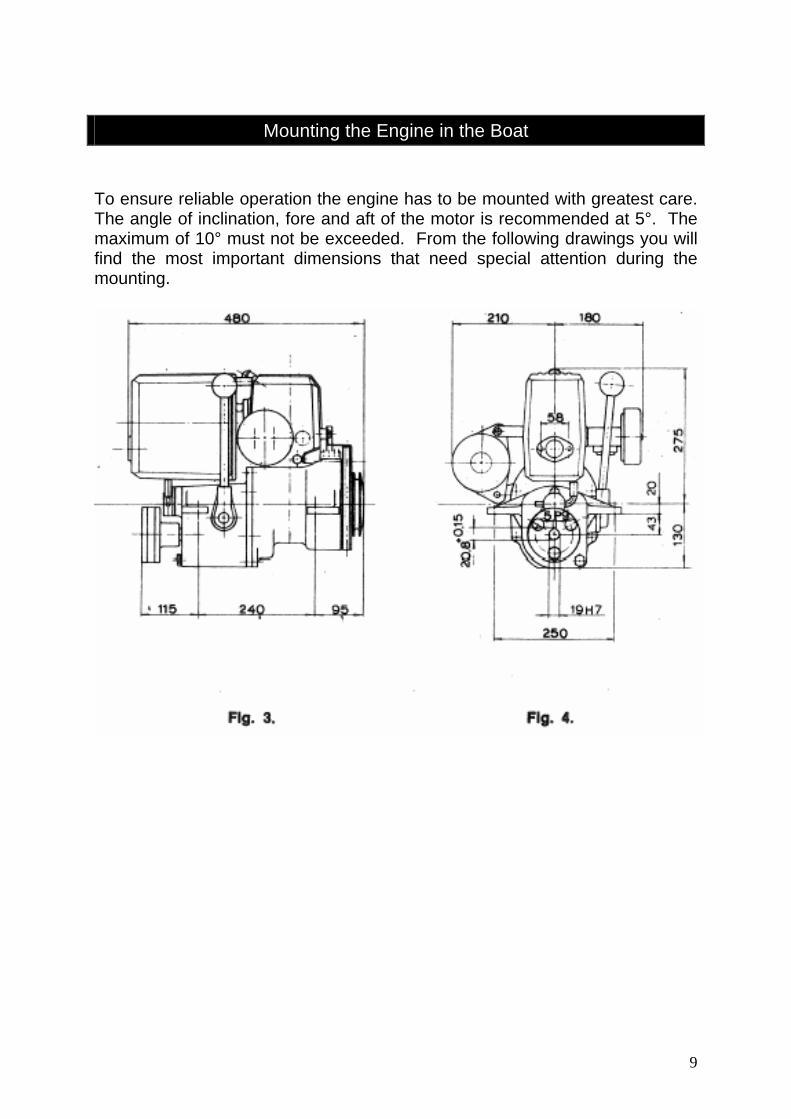
Mounting the Engine in the Boat
To ensure reliable operation the engine has to be mounted with greatest care. The angle of inclination, fore and aft of the motor is recommended at 5°. The maximum of 10° must not be exceeded. From the following drawings you will find the most important dimensions that need special attention during the mounting.
9

Engine Bed Requirements The engine bed should be sturdy and of solid construction. It is also advisable to make the fore and aft bearers as long as possible, so that thrust will be transmitted through frames or ribs. The bed must also be firmly fixed to the transverse members. It is advisable to arrange the height of the engine bed so that shims or thin packing pieces can be inserted under the engine bearers. It will then be possible to obtain accurate alignment by removing or increasing the number of shims. Alignment should be checked at the beginning of and at least once during each season, as it is common for some craft to undergo slight changes in shape according to weather and drying out due to laying up conditions. Installation of the Engine and Propellor Shaft It is most important that the engine shaft and propellor shaft are in accurate alignment. The propellor shaft does not need any extra thrust bearing, as the rear bearing of the engine is capable of receiving the thrust. The propellor shaft system and the engine should be first assembled approximately in line. The exact centralisation and lining up is carried out by moving the engine little by little, after the propellor shaft system has been finally installed. When checking the final alignment of the engine, the fixing bolts of the engine should first be tightened, then remove the screws and the flexible disc of the coupling. The position of the engine is correct when the coupling flanges are completely parallel in all directions and centralised. The parallelism of the flanges can be confirmed by means of a feeler gauge. If the distance between the flanges varies in any direction, the engine has to be moved sufficiently to correct any misalignment. When correct alignment is achieved, reconnect the coupling. Remove the spark plug and turn the shaft by hand. If the shaft rotates freely and evenly the engine/propellor shaft alignment is correct. When using a stern tube provided with a rubber-sleeve-mounted front bearing, the front end of the propellor shaft has to be centralised carefully to the stern tube before final checking is made. The centralisation is best achieved by disconnecting the sleeve, sliding the bearing assembly forward and locating the shaft in the tube with small wedges.
10

Exhaust and Cooling Systems Despite the presence of cooling water, exhaust gases leaving the exhaust gas collector are still quite hot. The temperature of exhaust gases depends on the load and it can be as high as 300°C. If a hot exhaust pipe is acceptable it can be left dry (fig. 5.1), and the cooling water can be led from the cylinder directly to a discharge-overboard fitting. However, a hot exhaust pipe is to be avoided because of thermal radiation and risk of fire. If unavoidable, the recommended system is shown in fig. 5.2. The exhaust pipe must be raised immediately after the exhaust gas collector to a height sufficient to prevent sea water getting through the exhaust pipe to the engine (see fig. 5.2). If there is no need to use a water jacket (fig. 5.4) on the rising part of the exhaust pipe, cooling water is led directly into the exhaust pipe. In such a case the rising part of the exhaust pipe is hot and it has to be properly isolated and insulated from its surroundings. Because the temperature of the cooled part of the exhaust pipe does not exceed 100°C, the pipe can be made out of suitable plastic or rubber materials. In some cases it is not possible to get the bend of the exhaust pipe high enough. In such cases, it is recommended to use a system as given in fig 5.3. When it is necessary to cool the exhaust pipe, it can be arranged by leading a small amount of the cooling water through a regulator cock into the exhaust pipe. In this system, the main part of the cooling water is led from the cylinder directly through the hull fitting. However, when using this system the regulator cock must be opened immediately after starting engine and closed before stopping the engine if the engine is below or on the waterline.
11

12
The exhaust pipe must be installed so that any water coming past the exhaust pipe or condensing from exhaust gas in the exhaust pipe cannot flow into the engine. Additional Installation Notes a. When installing fuel pipes, absolute cleanliness must be observed. The fuel
pipe can be made of suitable ¼" inside diameter plastic hose. b. If the engine is placed into a confined space, e.g. a sailing boat, special
care must be taken to provide adequate ventilation in order to avoid fire risk.
c. The starter battery must be firmly installed and must have easy access and adequate ventilation. Electrical components and cables must be mounted in such a way that vibration and dampness cannot cause any breakdowns. Connections of electrical components are shown in figs 7 and 8.
PRELIMINARY MEASURES BEFORE PUTTING INTO SERVICE
Fuel and Lubricants Any regular grade of gasoline may be used. It is not necessary to use high octane or super grade fuel. The gasoline should always be mixed with suitable engine oil, to the proportion of 1 part oil to 33 parts gasoline, (1 part to 20 for the first 10 running hours). When filling the tank with fuel, use a fine mesh or chamois leather filter. The gearbox should be filled to the level between the end and the mark of the dip stick. Use gear oil SAE 140 for the initial 50 hours, thereafter use SAE 90 gear oil. Capacity 1½ Imperial pints (1¾ U.S. pints). The grease cup on inboard sterntube bearing should be filled with good quality water pump grease. Preparation of a New or Stored Engine After storage, before the engine is put into service, the conserving oil (see laying-up para) must be drained from the crankcase. This is simplified by pouring a cupful of 2-stroke fuel into the crankcase and then swinging the engine several times to and fro. The mixture is then drained out through the draining screw hole at the bottom of the crankcase. The preserving oil in the cylinder is removed in a similar manner, by pouring a spoonful of fuel through the spark plug hole, when the piston is in halfway position. The engine should then be rotated rapidly by the start cord, the mixture blowing out through the spark plug opening.
13

Starting (See Maintenance – page 20 refers.)
1. Check that adequate fuel available in fuel tank. 2. Make sure that gear lever is in the neutral position. 3. Open fuel cock (if fitted). If using a portable fuel tank, pump fuel with the
hand pump until resistance is felt. 4. Open sea cock. 5. Turn the choke lever on the carburettor to the upright position. 6. Open the throttle about one third. 7. Crank the engine with the starting key. 8. *Wind the starter cord onto the start pulley and turn the engine slowly
until compression is felt, then continue turning engine to a position just over compression.
9. *Start the engine by pulling strongly and evenly on the starter cord. 10. When the engine has started turn the choke off slowly and use the
throttle to regulate the speed accordingly. 11. If a supply of water is led into the exhaust manifold through a cock, this
should now be opened. 12. Move the gear lever into the required driving direction. The speed of
the boat is now adjusted by means of the throttle lever. * Manual Start
Starting a Warm Engine Starting is generally the same as for a cold engine, but the choke lever (fig. 6) should be left in the run position (see above). No choke is used, because the mixture will be too rich and the engine will not start. If the engine has been 'flooded' or 'over-primed' the engine will not start. Proceed as follows: - Check that the choke is off (i.e. not in the position shown in fig. 6), close the needle valve (part 5) and rotate the engine several times vigorously while the throttle valve is completely open. As soon as the engine starts set the needle valve (part 5) to the best position, and adjust speed of the engine by means of throttle. A very hot engine may refuse to start, even if not 'flooded'. In this case the best thing is to open the throttle valve (part 1) fully open, turn off the fuel and give the engine several vigorous false starts. The engine normally will start, after which close the throttle to desired speed and turn on fuel. REMEMBER: NO CHOKE WHEN ENGINE IS HOT.
ENGINE OPERATION Engine speed and gearbox control 1. Open the throttle lever to a 'fast idle' speed. 2. Move the gear lever in the required direction (movement is 'instinctive').
WARNING! Seizure of and serious damage to the taper drive cone faces in the gear box can take place if either forward or astern gear is selected
14

with the engine running too fast. Set engine speed just high enough to avoid stalling of the engine when the gear is engaged. The speed of the boat is adjusted by means of the throttle lever. Carburettor idling set screw should be positioned so that a hot engine will not cut out when the throttle is closed with the engine in gear.
Running-in Period Careful use during the first 10 hours will increase the life of the engine. For the first five hours of a half throttle, after which the throttle opening can be gradually increased until at 10 hours it is safe to use full throttle. The engine will not develop full power for about 50 hours when all bearing surfaces will have become properly bedded in. For the first 10 hours it is advisable to use a slightly higher oil content in the fuel, i.e. 1 : 20. After the 10 hours running-in period, change to the normal 1 : 33 oil : fuel ratio. So-called Super Outboard Oils (BIA Type TC-W) are recommended. When running, check the flow of cooling water overboard and through the exhaust. During a long run, give an occasional turn to the grease cup of the stern tube bearing. Stopping the Engine 1. If cooling of the exhaust pipe is arranged as in fig. 5.4, close the water
cock. 2. Place the throttle to the idling speed position. 3. Place the gear lever into the neutral position. 4. Operate the ignition stop switch. 5. Close the fuel cock. 6. Close the sea cock.
NOTE: If the boat lies idle for some time, it is advisable to rotate the engine by means of the flywheel until compression is felt. When the piston is in this position, it closes the ports in the cylinder wall, so preventing humidity from entering the engine.
CONSTRUCTION OF THE ENGINE General Data The Vire 7 engine is designed and built for marine use. The engine is supplied with a reversing gearbox and with its hand lever it is possible to select forward, neutral and reverse positions. The reduction ratio is 2 : 1. When moving forward the propellor rotates in the opposite direction to the engine. A flywheel magneto supplies current for ignition and a 6 volt 16 watt AC current for lighting, if required. The engine is supplied with a 12 volt starter generator; the power output of which, as a generator, is 90 watt. The carburettor is of membrane type, which guarantees the feeding of fuel irrespective of engine angle when the boat is under-way. A vane type pump
15
provides cooling water circulation. There is no thermostat in the cooling water system. Engine The engine is a single-cylinder, water cooled 2-stroke. The cylinder and cylinder head are cast in one piece. In order to achieve even running of the engine, an exhaust gas collector with a water jacket is fitted. This collector is beneficial in a 2-stroke engine, where the length, diameter and shape of the actual exhaust pipe and silencer can vary from boat to boat. In order to reduce weight, the collector has been made of light alloy. Because of this, the collector is water-cooled. This also reduces thermal radiation to the engine space and cools the exhaust. Cooling An impellor type water pump is fitted and is driven through an extension of the gearbox idler gear shaft. The sea water suction line is connected directly to this pump, which pumps water through the exhaust collector water jacket and thence into the cylinder block. Because of this system, the cooling water is thereby maintaining the engine water temperature at an acceptable level under all running conditions. Water discharge can either be: - a) discharged overboard directly, or b) injected into the exhaust system at a point above the water line and used to cool the exhaust system, thus enabling rubber petrol-proof exhaust hose to be used for this water cooled section. (See installation details - EXHAUST PIPE AND COOLING WATER PIPING). Threaded plugs are fitted to the cylinder and the exhaust gas collector for the purpose of draining the system. Carburettor A diaphragm pump operated by pressure fluctuations in the crankcase is incorporated in the carburettor. The advantage of this type of carburettor is that it will function under all conditions of heel. Fuel is drawn through a strainer into the pump chamber and is then transferred to the carburettor chamber where it is metered and controlled by a needle valve and the idling and main jets. A choke is fitted in the carburettor venturi to assist cold starting.
16

Fig. 6. Carburettor 1. Throttle lever 2. Idle speed screw 3. Choke lever 4. Idle mixture screw 5. High speed mixture screw 6. Fluctuating pressure tube 7. Strainer cover 8. Air filter. Magneto Ignition is supplied by a flywheel magneto, which also incorporates a 6 volt lighting supply, if required. Wiring diagram showing this system is shown in fig. 7. The total power absorbed must not exceed 16 watt 6 volt.
17

Fig. 7 Wiring diagram for the lighting current in an AC system
18
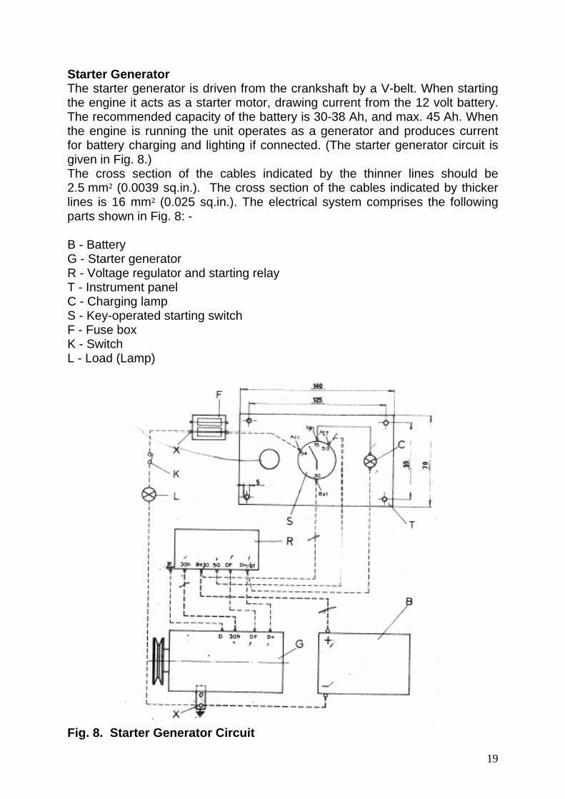
Starter Generator The starter generator is driven from the crankshaft by a V-belt. When starting the engine it acts as a starter motor, drawing current from the 12 volt battery. The recommended capacity of the battery is 30-38 Ah, and max. 45 Ah. When the engine is running the unit operates as a generator and produces current for battery charging and lighting if connected. (The starter generator circuit is given in Fig. 8.) The cross section of the cables indicated by the thinner lines should be 2.5 mm² (0.0039 sq.in.). The cross section of the cables indicated by thicker lines is 16 mm² (0.025 sq.in.). The electrical system comprises the following parts shown in Fig. 8: - B - Battery G - Starter generator R - Voltage regulator and starting relay T - Instrument panel C - Charging lamp S - Key-operated starting switch F - Fuse box K - Switch L - Load (Lamp)
Fig. 8. Starter Generator Circuit
19
Reversing Gear The reversing gear is coupled directly to the rear part of the engine. The propellor thrust is taken up within the gear; forward and reverse action being provided by two cone clutches on a splined shaft.
MAINTENANCE Regular Periodic Service Regular service is essential for trouble-free use of the engine. The following maintenance instructions should be adhered to. Beginning of the Season (a) Remove excess protective oil from cylinder and crankcase (b) Remove external protective greasing (c) Clean carburettor and fuel pump (d) Clean spark plug and check gap (e) Check magneto contact breaker points gap and lubricate felt oiling pad (f) Fill reversing gearbox with new oil (g) Fill grease cup of the stern tube bearing with HMP grease (h) Check condition and tightness of starter generator V-belt (i) Check all electrical connections (j) Check condition of battery Checks Before Normal Starting (a) Fuel tank full (Do not use last season's fuel) (b) Tightness of starter generator V-belt (occasionally) (c) Check fuel and cooling system for leaks (d) Lubricate stern tube bearing
20

Every 50 Hours Running (a) Clean spark plug and check gap (b) Clean carburettor strainer (c) In a new engine - change oil in reversing gear (d) Check electrolyte level in battery Every 100 Hours Running (a) In addition to above mentioned servicing, change the oil in the reversing
gear Every 300 Hours Running (a) In addition to the above mentioned servicing, check the magneto
breaker points gap and adjust it if necessary (b) Clean carburettor Recommended Lubricants Lubricant Amount Stern tube bearing (grease cup) HMP grease Reversing gear - Temp above 10°C SAE 140 0.7 litre Reversing gear - Temp below 10°C SAE 90 0.7 litre Lubrication of Reversing Gear The reversing gearbox is filled with oil to the point where the tip of the dipstick just enters the oil when the dipstick is screwed down and the engine is in its normal position in the boat. The mark on the dipstick shows the absolute upper limit for the oil level. The amount of oil is 0.7 litres.
21

Checking the Spark Plug When setting the spark plug gap, adjust the earth connection electrode, not the middle electrode. The gap should be set to 0.50 mm. About 99 per cent of running and starting difficulties in 2-stroke engines originate in the plug. If your engine has been running well and for some unexplained reason starts developing starting or running faults, always check the plug first. Better still, fit a known serviceable spark plug and have the other cleaned and re-gapped. Always keep with you at least one serviceable plug wrapped in a plastic bag. Do not leave it in the boat. Take it from your dry and warm home to the boat each trip. If you know that there is fuel and compression - that the engine is not 'flooded' or over/under choked - and yet it still will nor start after four or five attempts - save yourself a lot of wasted effort by checking the plug. In nine out of ten cases cleaning the plug will effect a cure and the other one out of ten cases will almost certainly be corrected by a change of plug. Laying the plug on the cylinder head with the high-tension (HT) lead connected and engine rotated will tell you if the plug is sparking, but you should for a good 'fat' blue spark. A plug that gives a thin or white spark may not spark at all when under compression in the cylinder. The best rule with spark plugs is 'WHEN IN DOUBT, HEAVE IT OUT'! Dampness in Magneto If there is any reason to suspect that there is dampness in the magneto, remove the rope starting pulley and spray dampness remover e.g. CRC 5-56 through the flywheel holes into the magneto. If the engine will not start after this procedure, remove the flywheel and armature and dry it properly. The above-mentioned dampness remover can also be used on other electrical devices in the engine. Cleaning the Carburettor Strainer In order to clean the carburettor strainer, remove the screw and cover from the bottom of the carburettor, taking care not to damage the gasket. Wash the strainer with petrol, and dry. When putting the strainer back, check the gasket and fit the cover with care to avoid leaks.
22
Cleaning the Carburettor When the engine is laid up for a long period, the lubrication oil can separate from the fuel and clog the carburettor. In such a case, remove the screw of the idling speed nozzle and the screw of the main nozzle, but being careful not to lose any springs, washers or sealing rings. Put a can under the carburettor and let the fuel flow for some time through the screw holes. If the fuel tank lies below the carburettor, a flow can be created by removing the spark plug and rotating the engine by hand. After this, replace the nozzle screws and adjust the carburettor. If you have to strip the carburettor, ensure cleanliness and handle membranes and their sealing surfaces with care. An air leak on a sealing surface, valve or connection can cause a malfunction in the carburettor. In order to clean internal channels, use petrol and compressed air. Do not, under any circumstances, use steel tools, needles or similar articles to clear internal blockages. Cleaning the Air Filter The air filter is of the dry type. Wash the filter at the end of the season and/or when required.
ADJUSTMENTS Adjusting the Carburettor Idling Speed: Clean and check spark plug gap. Unscrew idling jet screw (part 4 fig. 6) 1¼ turns. Start the engine and run until warm. With the gear lever in neutral, set the speed to 1200 r.p.m. At this speed, the engine will tend to 'four-stroke'. Place the gear lever in the 'ahead' position. The speed should not fall below 1000 r.p.m. If the speed is less, adjust the idling stop screw (part 2) until the engine is running at 1000 r.p.m. Full Power: Open the main jet 1¼ turns, and test the unit on full power. Depending on the type and size of boat, adjustment either way on the main jet may be required to obtain maximum speed. For obvious reasons, this final setting of the main jet must be carried out with the boat under way.
23

Adjustment of the Magneto Breaker Point Gap The breaker point gap in a new engine is adjusted at the Factory to its proper value. After 300 running hours it may be necessary to check the gap and possibly readjust it. The following procedure should be adopted: Remove the starting pulley and rotate crankshaft until breaker point gap is at maximum. The breaker point gap should be set to 0.45 mm (0.016”) by means of a feeler gauge. Adjustment of the gap is carried out by loosening the screw 1 (fig. 9) and turning point 2 from notch A. Retighten screw 1.
Timing Adjustment The timing is adjusted at the factory to its proper value to give the greatest efficiency and starting characteristics. If the magneto statorplate has been removed it must be fitted so that the fixing screws pass centrally through the oval shaped slots. This will ensure the correct timing, provided that the magneto contact breaker points gap is correct. If rechecking or adjustment of the timing is needed, the following procedure should be adopted: Adjust the magneto breaker point gap to its proper value. Turn flywheel clockwise (direction of normal rotation) until the notch on the V-belt pulley indicates the fixing level of the bracket on the left side of the engine (seen from the front end, fig. 1). The breaker points should just open at this position, 30°B.T.D.C. The only accurate way to check this is with a buzzer type continuity tester. If the timing is correct sound change is noted at this position. Loosen the fixing screws of the stator plate and shift the plates clockwise if points too early and counter clockwise if points too late, until timing is correct. Tighten the fixing screws and recheck gap setting. A timing mark, 30° B.T.D.C. corresponds to the position of the piston in the cylinder being 5.9mm (0.23”) B.T.D.C which can be measured with a depth gauge type timing tool through the spark plug hole.
24

DISMANTLING AND ASSEMBLY INSTRUCTIONS
Dismantling the Engine
Flywheel Removal: (a) Remove the V belt cover and V belt (b) Remove the fixing screws of the starting pulley and remove pulley (c) Using the special puller supplied, fit it to the flywheel with screws and
tighten the puller centre screw against the end of the crankshaft (d) Tap the head of the puller screw lightly with a hammer to loosen and the
flywheel should be easily removed from the cone. To Open the Crankcase (a) Drain oil from the reversing gear (b) Remove exhaust gas collector (c) Remove starter generator and V belt cover (d) Remove flywheel (e) Remove fixing screws of the reversing gear and loosen by use of a hide
hammer. Do NOT force between the flanges (f) Remove cylinder (g) Remove fixing screws between the two halves of the crankcase and
separate the two halves Remove crankshaft from crankcase
Engine Assembly
Notice: If the crankshaft is damaged, return it to the Manufacturer or to a Workshop recommended by the Manufacturer, to be repaired.
Oil lightly all moving parts and shaft seals, paying particular attention to cleanliness.
25
The assembly is carried out in the following sequence: (a) Assemble the bearings on the crankshaft and, using a suitable sleeve,
knock on the inner ring of the bearing until it is in its correct position (b) Assemble the shaft seals, taking care not to damage them (c) Fit crankshaft to the rear part of crankcase, coat the sealing surfaces
evenly with sealing compound and assemble front part of crankcase on the crankshaft, ensuring the cylinder head joint surface is level
(d) Tighten the fixing screws (e) Check assembly of all parts installed so far by rotating crankshaft (f) Fit piston assembly ensuring that the piston ring grooves face the
flywheel end of the engine (g) Assemble cylinder and its gasket (h) Assemble magneto armature, flywheel and starting pulley (i) Refit reversing gear (j) Assemble starter generator, V belt, V belt cover, carburettor and
exhaust gas collector
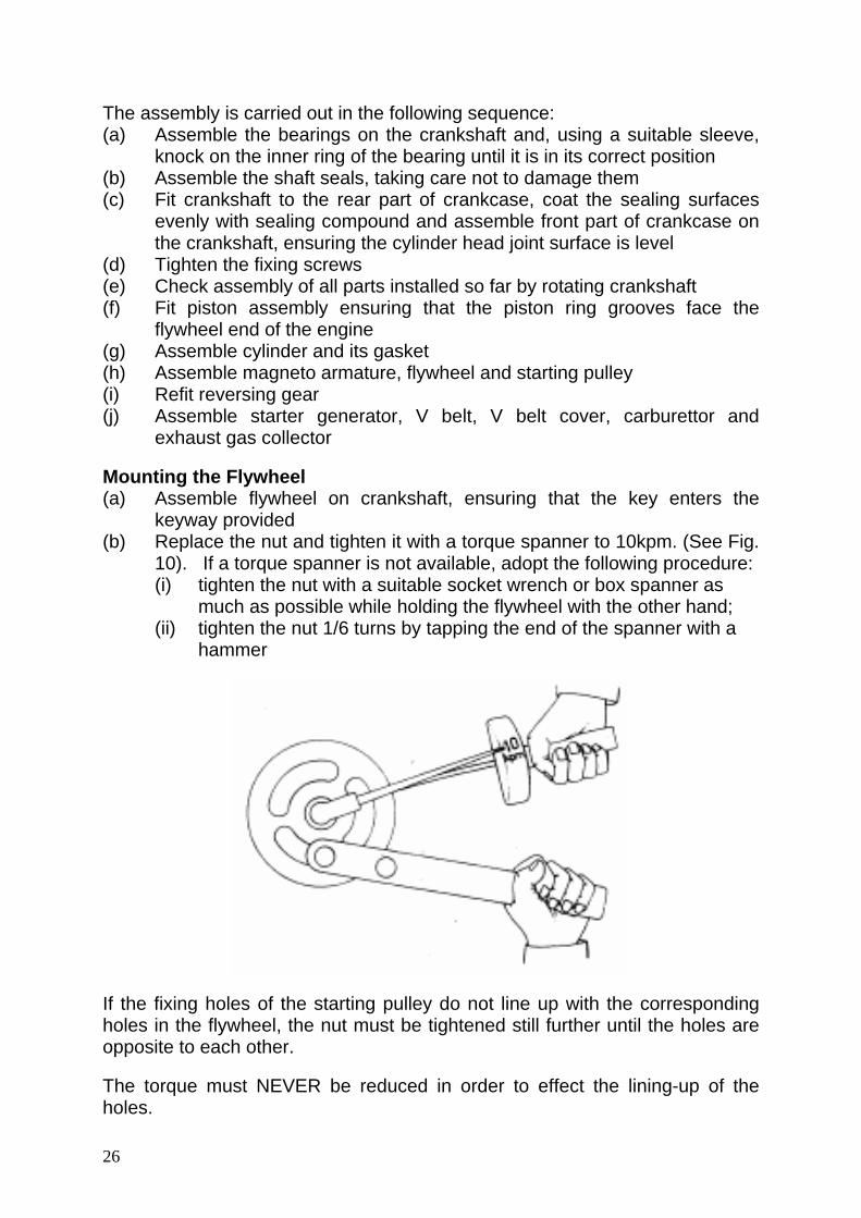
Mounting the Flywheel (a) Assemble flywheel on crankshaft, ensuring that the key enters the
keyway provided (b) Replace the nut and tighten it with a torque spanner to 10kpm. (See Fig.
10). If a torque spanner is not available, adopt the following procedure: (i) tighten the nut with a suitable socket wrench or box spanner as
much as possible while holding the flywheel with the other hand; (ii) tighten the nut 1/6 turns by tapping the end of the spanner with a
hammer
If the fixing holes of the starting pulley do not line up with the corresponding holes in the flywheel, the nut must be tightened still further until the holes are opposite to each other.
The torque must NEVER be reduced in order to effect the lining-up of the holes.
26
Dismantling the Reversing Gear (a) Drain oil from reversing gear (b) Remove reversing gear from engine using a similar procedure to
"Dismantling the Engine" (c) Remove water pump by removing the housing fixing screws, removing
the case, impellor and gasket (d) Remove the coupling flange using the impellor puller supplied (e) The shafts are removed from the casing by pulling them forward. Use a
hide hammer on the rear part of the shaft if trouble is experienced (f) The operating crank can be removed from the gear lever by removing
the taper pin in the end of the shaft. When removing the operating crank care should be taken not to lose the spring and locating pin
(g) Remove operating crank from inside (h) The gear wheel of the reversing gear and its bearing can be removed by
removing the locking ring from the shaft end (i) When removing the bearings care should be taken that no damage is
done on to the cone surfaces and the splined shaft
Reassembling and Refitting the Reversing Gearbox (a) Assemble shaft seals (b) Assemble shaft bearings using pressure on the inner ring of the bearing (c) Complete the main shaft assembly (cones, gear wheels, bearings and
retaining rings)
27

(d) Assemble the main shaft bearings, using shims where necessary (e) Assemble gear lever and operating crank (f) Refit shafts (g) Refit water pump assembly (h) Assemble sleeve, key and coupling flange on the external end of the
main shaft (i) Refit the reversing gear to the engine (j) Check end play of the propellor shaft, which should be approximately
0.1mm. If necessary, adjust with suitable adjusting shims (k) Fill reversing gear with oil (see page 21)
STORAGE OF THE ENGINE
When laying up the engine for the winter or if it is not used for a considerable period, ideally, the engine should be removed from the boat and stored in a cool dry location suitably covered to protect from dirt or dust. If this is not possible, the following procedure should be adopted: -
• Remove the air filter, start the engine, and spray protective oil (Part No. 50173) into the manifold
• Clean the engine externally • Open the plug on the cylinder block (Fig. 11 Ref. No. 11) and the plug in
the sound absorber (Fig. 16 Ref. No. 8). Secure that all water comes out. • If protective oil in a spray bottle is not available, proceed in the following
four stages: o Remove the carburettor, spark plug and V belt o With the piston at Top Dead Centre, pour about ¼ Pint of oil through
the suction point into the crankcase o Turn the piston down to Bottom Dead Centre and tilt the engine so
that the oil can flow onto the bearings o Turn the piston again to its Top Dead Centre and pour about a
spoonful of motor oil through the spark plug hole into the cylinder • Rotate the crankshaft two or three turns, leaving it in mid-stroke position, so
that the cylinder ports are covered • Replace spark plug and grease all exposed metal parts • For protection of electrical components, a suitable insulation spray may be
used • Clean the battery, check electrolyte level and charge
28

TABLE OF TROUBLES AND THEIR CAUSES
29

VIRE 7
Spares List
30

SPARE PARTS LIST
When ordering spare parts, the type of engine, Serial No., name of part, Spare Part No. and the quantity have to be mentioned. Example: Vire 7 No. 20403, Piston (Std.), 520 720, 1 piece Ref. No Name of Part Westerbeke
Part No. Vire
Part No. Quantity
Fig.11 1 Hex. screw M 6 x 10 15816 520 790 1 2 Sealing ring / washer 18264 520 600 2 3 Front part of the crankcase 18199 520 020 1 4 Sealing ring / washer 15856 520 630 6 5 Screw (Allen Head) 18255 520 040 6 6 Shaft seal 30mm x 52mm x 7mm 15851 520 740 2 7 Clip / Crankcase breather 18273 520 140 1 8 Stud M 8 x 22 15828 520 850 2 9 Hex. nut 15889 520 880 2 10 Sealing ring / washer 18263 520 210 1 11 Threaded plug 18270 520 200 1 12 Stud M 6 x 15 18249 520 820 2 13 Washer ø 6.4 15800 307 090 2 14 Hex. nut M 6 18241 306 020 2 15 Cable holder / clip 18198 520 500 2 16 Hex. nut M 5 - 443 860 2 17 Support plate 18217 520 490 1 18 Cylinder 18227 520 160 1 19 Stud M 8 x 20 18250 520 830 4 20 Elastic disc / washer 18239 334 160 4 21 Hex. nut M 8 18242 307 550 4 22 Angle / elbow clip 18208 520 750 1 23 Plug / frost bung / anode 30mm 18269 520 190 2 24 Plug / frost bung / anode 25mm 18268 520 180 1 25 Gasket 0.20 mm 15882 520 550 1 26 Hex. nut 15887 520 890 1 27 Stud M 10 x 22 15832 520 840 1 28 Gasket 0.20 mm 18207 520 570 1 29 Breather / vent 18271 520 620 1
31

Ref. No Name of Part Westerbeke
Part No. Vire
Part No. Quantity
30 Rear part of the crankcase 18200 520 030 1 31 Rubber ring / grommet 15890 520 610 2 32 Hex. screw M 5 x 10 - 520 510 2
Fig.12 1 Starting wheel / pulley 18205 520 220 1 2 Screw 18254 520 800 4 3 Flywheel / pulley 18206 520 660 1 4 Hex. Nut M 16 15814 520 870 1 5 Hex. Screw M 6 x 15 18246 520 690 4 6 Woodruff key for starting wheel 15891 520 780 1 7 Ball bearing 30 x 72 x 19mm 18260 520 730 2 8 Crankshaft, front part 18202 520 060 1 9 Piston complete incl. rings & pin 18195 520 720 1 - Piston complete 0.5 mm oversize 15972 522 060 1
10 Piston pin 15883 522 070 1 11 Circlip for piston pin 15861 522 080 2 12 Piston ring 15885 522 090 2 - Piston ring 0.5 mm oversize 15974 522 100 2
13 Piston ring chrome plated 15973 522 110 1 - Piston ring chrome plated 0.5 mm
oversize 15975 522 120 1
14 Small end bushing 15880 520 120 1 15 Connecting rod 18196 520 110 1 16 Bearing of the connecting rod 15848 520 130 1 17 Crank pin 18261 520 080 1 18 Rear part of the crankshaft 18203 520 070 1
Crankshaft assembly complete - 520 050 1 Fig. 13
1 Magnet ring / flywheel 15963 522 130 1 2 Breaker cam 15961 520 670 1 3 Breaker points 15958 522 140 1 4 Ignition coil 15959 522 150 1 5 Screw with cylindrical head 15970 522 160 4 6 Cable - 522 170 1 7 Lubrication felt 15967 522 180 1 8 Auxialy lighting coil 15962 522 190 1 9 Spring disc / washer 18238 522 200 4 10 Capacitor / condenser 15957 522 210 1 11 Armature complete 15965 522 220 1 12 Cable cover - 522 230 1 13 Ignition cable 18274 522 240 1 14 Securing plate A 51 - 520 910 5
Ref. No Name of Part Westerbeke Vire Quantity
32

Part No. Part No. 15 Screw M 5 x 15 18253 333 700 3 16 Screw AM 3 x 20 18252 520 860 2 17 Connection rail, 4-poles 18209 520 700 1 18 Screw AM 5 x 8 - 333 890 3 19 Earth connection cable - 520 520 1 20 Spark plug 15945 522 601 1 21 Connector plug for ign. Cable 15971 477 900 1 100 Fixing screws - 534 630
Fig. 14 1 Coil No. 1 522 250 1 2 Coil No. 2 522 260 1 3 Coil No. 3 522 270 1 4 Coil No. 4 522 280 1 5 Bearing shield, driving end 522 290 1 6 Bearing shield, collector end 522 300 1 7 Protecting belt 522 310 1 8 Brush spring 522 320 4 9 Carbon 522 330 4 10 Ball bearing, collector end 522 340 1 11 Armature with bearings 522 350 1 12 Wedge 522 360 1 13 Ball bearing, driving end 522 370 1 14 Spring washer 522 380 1 15 Hex. nut M 14 x 1.5 522 390 1 16 V-belt cover 520 960 1 17 Hex. screw M 8 x 18 520 980 2 18 Elastic disc 334 160 5 19 Disc 521 150 1 20 Hex. screw M 10 x 40 520 990 1 21 Tightening iron 520 950 1 22 Hex. nut M 8 307 550 1 23 Hex. screw M 10 x 40 521 000 1 24 Spring washer B 10 521 030 2 25 Hex. nut M 10 521 020 2 26 Voltage regulator 521 110 1
33
Ref. No Name of Part Westerbeke
Part No. Vire
Part No. Quantity
27 Hex. screw M 10 x 65 521 010 1 28 Sleeve 520 970 1 29 Belt pulley 520 940 1 30 V-belt 521 040 1
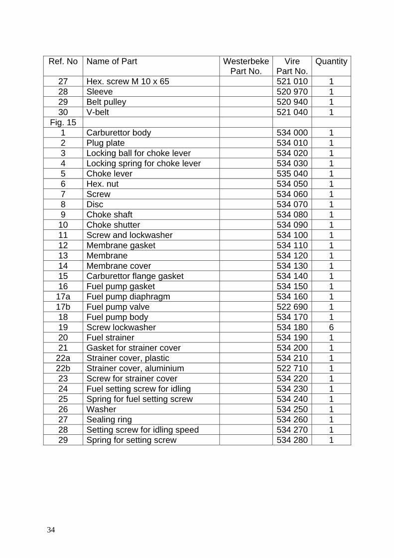
Fig. 15 1 Carburettor body 534 000 1 2 Plug plate 534 010 1 3 Locking ball for choke lever 534 020 1 4 Locking spring for choke lever 534 030 1 5 Choke lever 535 040 1 6 Hex. nut 534 050 1 7 Screw 534 060 1 8 Disc 534 070 1 9 Choke shaft 534 080 1
10 Choke shutter 534 090 1 11 Screw and lockwasher 534 100 1 12 Membrane gasket 534 110 1 13 Membrane 534 120 1 14 Membrane cover 534 130 1 15 Carburettor flange gasket 534 140 1 16 Fuel pump gasket 534 150 1 17a Fuel pump diaphragm 534 160 1 17b Fuel pump valve 522 690 1 18 Fuel pump body 534 170 1 19 Screw lockwasher 534 180 6 20 Fuel strainer 534 190 1 21 Gasket for strainer cover 534 200 1 22a Strainer cover, plastic 534 210 1 22b Strainer cover, aluminium 522 710 1 23 Screw for strainer cover 534 220 1 24 Fuel setting screw for idling 534 230 1 25 Spring for fuel setting screw 534 240 1 26 Washer 534 250 1 27 Sealing ring 534 260 1 28 Setting screw for idling speed 534 270 1 29 Spring for setting screw 534 280 1
34

Ref. No Name of Part Westerbeke
Part No. Vire
Part No. Quantity
30 Needle valve lever 534 290 1 31 Needle valve lever shaft 534 300 1 32 Screw for lever shaft 534 310 1 33 Needle valve and seal 534 320 1 34 Sealing for needle valve 534 330 1 35 Spring for needle valve lever 534 340 1 36 Setting screw 534 350 1 37 Spring for setting screw 534 360 1 38 Washer 534 370 1 39 Sealing ring 534 380 1 40 Nozzle 534 390 1 41 Throttle lever 534 400 1 42 Throttle lever fixing screw 534 410 1 43 Throttle shaft 534 420 1 44 Shaft retainer 534 430 1 45 Lockwasher 534 440 1 46 Screw 534 450 1 47 Returning spring 534 460 1 48 Throttle shutter 534 470 1 49 Screw and lockwasher 534 100 1 50 Fixing screw for throttle lever 534 490 1 51 Gasket set 534 500 1 52 Repair parts (*) kit 534 510 1 53 Bottom plate 520 400 1 54 Sieve net 520 420 1 55 Foam plastic 520 410 2 56 Sieve net 520 450 1 57 Case 520 390 1 58 Washer 53 520 900 2 59 Hex. screw M 5 x 45 520 810 2 60 Tightening belt 534 520 2 61 Hose 534 530 1 62 Fuel pump valve (=17b) 522 690 1 63 Forced fuel hose 522 700 1
Fig. 16 1 Hex. screw M 6 x 25 18248 521 690 3 2 Water pump body / housing 18216 521 220 1
35

Ref. No Name of Part Westerbeke
Part No. Vire
Part No. Quantity
3 Impeller 18212 360 360 1 4 Gasket 0.20 mm 18223 521 560 1 5 Washer / plate 18215 521 210 1 6 Hose 18210 520 380 1 7 Tightening belt / clamp / clip 17298 520 360 2 8 Threaded manifold drain plug 18270 520 200 1 9 Sealing ring / washer 18263 520 210 1
10 Sound absorber 18218 520 230 1 11 Gasket 18221 520 580 1 12 Water pipe - 520 340 1 13 Rubber hose - 520 350 1 14 Threaded plug 18275 520 320 1 15 Gasket 18272 520 580 1 16 Flange 15916 520 280 1 17 Stud M 8 x 18 18251 522 050 2 18 Hex. nut M 8 18242 307 550 2 19 Tightening belt / clamp / clip - 534 380 1
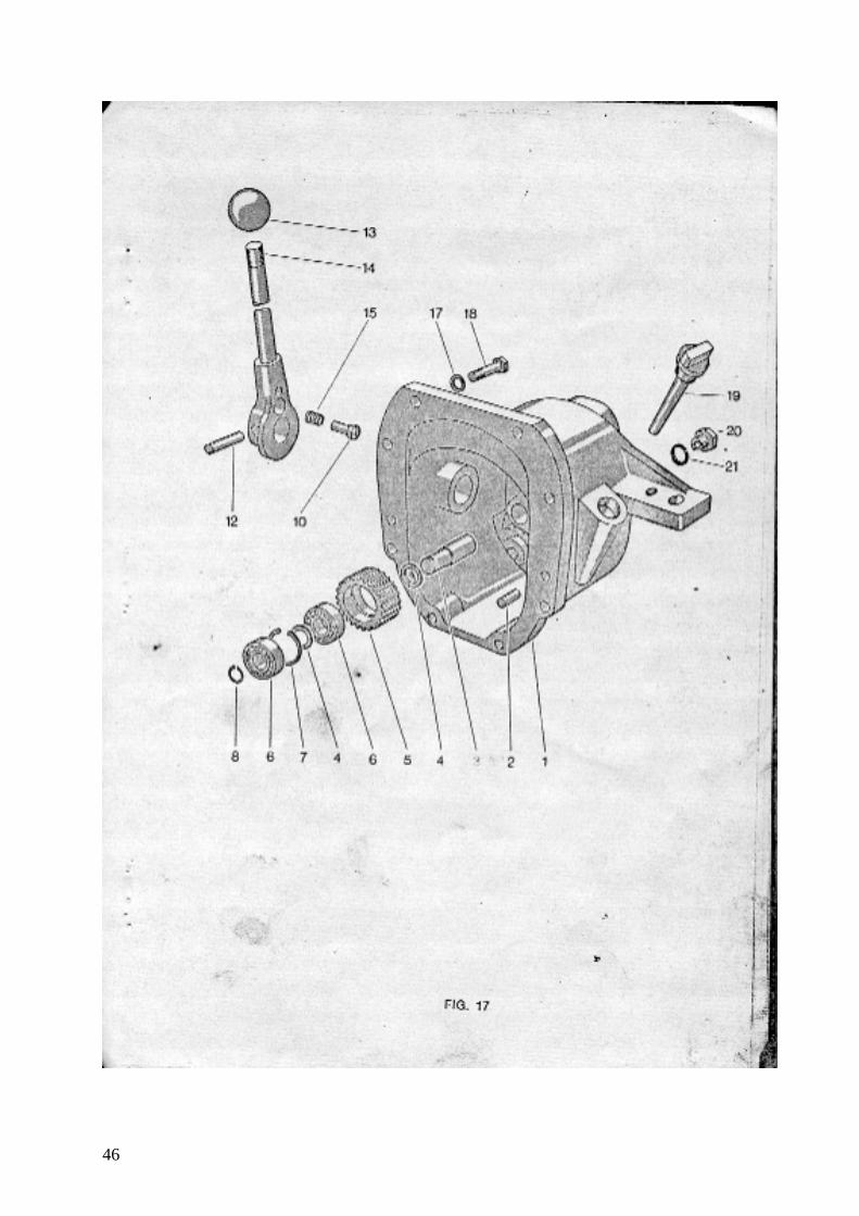
Fig. 17 1 Case /housing 18213 521 170 1 2 Cylinder split pin 15840 520 920 2 3 Shaft 15899 521 490 1 4 Washer 15900 521 500 2 5 Gear wheel 15901 521 510 1 6 Ball bearing 15845 331 240 2 7 Retaining ring 15862 306 120 1 8 Circlip 15859 521 640 1 9
10 Locking plug 18230 521 570 1 11 12 Elastic pin 18256 521 720 1 13 Ball knob 18225 521 740 1 14 Coupling rod / lever 18229 521 250 1 15 Spring 15871 521 480 1 16 17 Elastic disc - 334 160 6 18 Hex. screw M 8 x 30 15821 307 510 6 19 Dip-stick 18214 521 190 1 20 Magnetic drain plug M 12 x 1.25 15944 521 680 1 21 Gasket for magnet plug - 534 370 1
36

Ref. No Name of Part Westerbeke
Part No. Vire
Part No. Quantity
Fig. 18 1 Nut M 8 18245 521 450 6 2 Stud M 8 x 32 15831 521 470 3 3 Washer 15911 521 440 3 4 Coupling flange 15910 521 410 1 5 Hex. nut M 16 18244 521 700 1 6 Securing plate Ø / washer 18240 521 730 1 7 Elastic (rubber) disc / damper 15908 521 430 1 8 Coupling flange 15909 521 410 1 9 Stud M 8 x 25 15830 521 460 3
10 Washer - 344 030 3 11 Bush 15933 521 520 1 12 Shaft seal 25mm x 40mm x 7mm 15850 521 620 1 13 Roller bearing 20 x 47 x 12mm 15847 521 600 2 14 Thrust washer 18220 521 550 2 15 Safety ring 18267 521 660 4 16 Ball bearing 20 x 42 x 14mm 18259 521 590 2 17 Gear wheel 18219 521 540 2 18 Clutch cone 18201 521 180 1 19 Woodruff key / wedge 15912 521 710 1 20 Screw shaft 18204 521 530 1 21 Safety ring 18265 521 650 1 22 Shaft seal 15845 521 630 3 23 Coupling crank 18224 521 260 1 24 Woodruff key 18257 362 140 1 25 Driving shaft 18222 521 330 1 26 Woodruff key 18258 521 390 2 27 Gear wheel 15874 521 370 1 28 Gear wheel 15875 521 380 1 29 Ball bearing 12 x 40 x 16mm 15843 521 580 1 30 Shaft seal 15 x 30 x 7mm 18262 521 610 2 31 Safety ring 18266 521 670 2
37

Ref. No Name of Part Westerbeke
Part No. Vire
Part No. Quantity
Fig. 19 1 Propellor mounting nut 522 400 1 2 Securing plate 522 410 1 3 Propellor 2-blade 13” x 10” 522 420 1 Propellor 2-blade 10” x 13” 522 430 1 Propellor 3-blade 12” x 10” 522 440 1 4 Propellor shaft Ø 25 x 2000 522 450 1 Propellor shaft Ø 25 x required 522 459 1 5 Safety ring 522 460 1 6 Key 5 x 7.5 mm 522 470 2 7 Shaft seal 522 480 2 8 Front bearing of the prop. shaft 522 490 1 9 Rubber socket 522 500 1
10 Stern tube Ø 35 x 1500 522 510 1 11 Rear bearing of the propellor
shaft 522 520 1
12 Hose fastener Aris Nr. 1 522 530 1 13 Hose fastener Aris Nr. 2 522 540 1 14 Vaseline cup 522 550 1
Prop shaft assy 2000mm (# 1, 2, 4, 5 & 6)
522 670 1
Stern tube assy 1500mm (# 7-14) 522 680 1 Stern tube mounting flange comp. 522 720 1 Stern tube mounting flange comp. 522 730 1
Fig. 20 1 Charging lamp 521 090 1 2 Holder for charging lamp 521 080 1 3 Current switch 521 070 1 4 Earth connection switch 521 100 1 5 Panel 521 060 1 6 Rubber cover 521 120 1 7 Rubber cover 521 130 1 8 Fuse box 521 140 1 9 Hex. Nut M 6 306 020 2
10 Wire rope fastener 521 950 2 11 Hex. Screw M 6 x 15 521 960 2 12 Bottom valve 521 970 1 13 Starting rope 20923 521 800 1 14 Tube (flanged elbow) 20924 521 870 1 15 Plastic hose 20717 521 920 1 16 Nut - 521 770 1 17 Washer - 521 790 1 18 Sealing ring - 521 780 1
38

Ref. No Name of Part Westerbeke Part No.
Vire Part No.
Quantity
19 Suction pipe - 521 750 1 - Through-hull assembly (Parts
#15-#19) 20955
20 Bottom strainer 20925 521 910 1 21 Hex. wrench 20715 521 930 1 22 Flywheel puller 18197 521 830 1 23 Wrench for spark plug 20915 334 480 1 24 Solid wrench 12mm & 14mm 20925 521 900 1 - Toolkit complete (Parts #21-24) 20954
25 Seacock with hose connection - 522 740 1
39

40

41

42

43

44

45
46

47

48

49

50