1966 , volume , issue nov-1966 - about hp labs · voltmeter and the ability to measure voltage...
TRANSCRIPT

HEWLETT-PACKARD JOURNAL
C o v e r : A P R E C I S I O N D C D I F F E R E N T I A L V O L T M E T E R A N D R A T I O M E T E R ; s e e p a g e 2
S e e a l s o : A S Y S T E M F O R A U T O M A T I C A C Q U I S I T I O N O F S E M I C O N D U C T O R M A T E R I A L D A T A , p a g e 9 A S T U D Y O F I n A s D I F F U S E D W I T H G O L D , p a g e 1 6
NOVEMBER 1966 © Copr. 1949-1998 Hewlett-Packard Co.

A S I M P L I F I E D D C D I F F E R E N T I A L V O L T M E T E R A N D R A T I O M E T E R F O R
H I G H - P R E C I S I O N M E A S U R E M E N T S
An easy- to-use dc d i f ferent ia l vo l tmeter measures dc vo l t ages f rom 1 microvo l t to 1 1 00 vo l ts w i th a reso lu t ion o f 0 .2 m ic rovo l t and w i th h igh accu racy . The ins t rumen t i s a lso a precis ion rat iometer for comparing two dc vol tages.
MKASl REMENTS OK DC VOLTAGES and of res is tance and vol tage
r a t i o s a t a c c u r a c i e s b e t t e r t h a n a b o u t 3 0 p a r t s p e r m i l l i o n h a v e been genera l ly per formed in s tand ards laboratories by specially trained personnel . Now i t i s becoming nec e s s a r y t o m a k e m e a s u r e m e n t s a t these high accuracies in laboratory and product ion areas by engineers and test technicians with no special training. Strain gage measurements, l ine - and load- regu la t ion measure ments, noise measurements on solid s ta te c i rcui ts such as short - term in stabil i ty of zener diodes are among the c lass o l s i tua t ions where h igh a c c u r a c y a n d i n s t r u m e n t l e a d i n g stabili ty are required.
DC measurement accuracies in ex cess of 20 ppm can be achieved using i he differential method in which the unknown vol tage is compared with
a known precision reference voltage. If the precision reference voltage is a d j u s t e d t o b e e q u a l t o t h e u n k n o w n , t h e n t h e u n k n o w n c a n b e read to the accuracy of the precision reference.
Differen t ia l measurements have been commonly used in s t andards laboratories where precision sources and precision resistors are available. T h e s e t u p i s s o m e w h a t m o r e c o m plex than merely connect ing a vol t meter to the unknown, but the accu racy of differential measurements is better than 0.002% compared to the accuracy of direct-measuring analog instruments, which is of the onlei ol 0.5' ',',. Sell-contained instruments based on the di f ferent ia l pr inciple ha\e been available which olfer bet te r accuracies than di rec t measure m e n t m e a n s , b u t t h e y a r e c o m p l i cated to use.
Fig. 1. The -hp- Model 3420A / B Differential Voltmeter / Hatio- meter is a precision solid-state instrument capable of measuring dc railages from below 1 /tV to 1100 volts at resolutions of 0.2 ppm and accuracies of 20 ppm over much of this range. Measurements can also be made of resistance and collage ratios in four ranges from 1 to 0.001 to the name accuracy. The controls are color coded
and simplified so that readings can be made rapidly without the necessity of operating a complexity of controls.
Now, an instrument (Fig. 1) with the capab i l i ty o f a dc d i f fe ren t ia l voltmeter and the ability to measure voltage ratios l ias been designed to give an accuracy of ±0.002% of the reading (±20 ppm). The voltmeter i s s imple to ope ra t e and has been designed in both a power-l ine-oper ated version and a battery-operated v e r s i o n o p e r a t i n g f r o m s e l f - c o n tained rechargeable nickel-cadmium batteries. This capability to operate f rom a se l l -conta ined supply is im p o r t a n t w h e n m e a s u r i n g v o l t a g e s w i t h v e r y h i g h a c o r d c c o m m o n mode. Because the instrument is iso l a t e d f r o m t h e l i n e , t h e c o m m o n mode voltages do not influence the r ead ing . However , t he i n s t rumen t has good common mode r e j ec t ion when operated on the power line.
In the dc d i f f e ren t i a l vo l tme te r mode , the ins t rument measures dc voltages up to ±1100 volts in four ranges of ±1, 10, 100 and 1000. Volt age resolut ion i s 0 .2 microvol t , or 0.2 ppm of range.
V O L T A G E M E A S U R E M E N T
The bas i c componen t s o f the in s t rumen t i nc lude (F ig . 2 ) an accu r a t e a n d s t a b l e v o l t a g e s o u r c e , a p rec i s ion res i s tance d iv ider and a low-drift, high-sensitivity null detec tion meter.
An inpu t vo l t age app l i ed to the input terminals is applied directly to the decade dividers on the 1- and 10- volt ranges. On the 100- and 1,000- v o l t r a n g e s , t h e r a n g e a t t e n u a t o r r e d u c e s t h e v o l t a g e t o t h e 1 - v o l t
P R I N T E D I N U . S . A .
© Copr. 1949-1998 Hewlett-Packard Co.
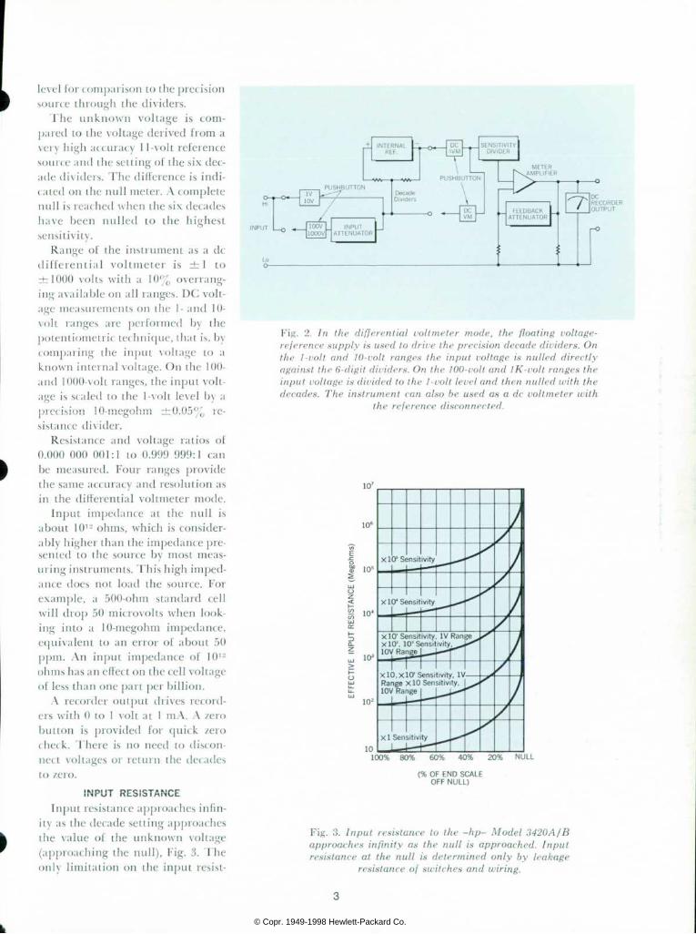
level for comparison to the precision source through the dividers.
The unknown vol tage i s com pared to the voltage derived from a very high accuracy 11-volt reference source and the setting of the six dec ade dividers. The difference is indi cated on the null meter. A complete null is reached when the six decades have been nul led to the highest sensitivity.
Range of the instrument as a dc differential voltmeter is ± 1 to ±1000 volts with a 10% overrang- ing available on all ranges. DC volt age measurements on the 1- and 10- volt ranges are performed by the potentiometric technique, that is, by comparing the input voltage to a known internal voltage. On the 100- and 1000-volt ranges, the input volt age is scaled to the 1-volt level by a precision I0-megohrn ±0.05% re sistance divider.
Resistance and voltage ratios of 0.000 000 001:1 to 0.999 999:1 can be measured. Four ranges provide the same accuracy and resolution as in the differential voltmeter mode.
Input impedance at the null is about 101- ohms, which is consider ably higher than the impedance pre sented to the source by most meas uring instruments. This high imped ance does not load the source. For example, a 500-ohm standard cell will drop 50 microvolts when look ing into a 10-megohm impedance, equivalent to an error of about 50 ppm. An input impedance of 101- olims has an effect on the cell voltage of less than one part per billion.
A recorder output drives record ers with 0 to 1 volt at 1 mA. A /ero
button is provided for quick /ero check. There is no need to discon nect voltages or return the decades to zero.
INPUT RESISTANCE Input resistance approaches infin
ity as the decade setting approaches the value of the unknown voltage (approaching the null), Fig. 3. The only limitation on the input resist-
Fig. 2. In the differential voltmeter mode, the floating collage- reference supply is used to drive the precision decade dividers. On the 1-volt and 10-uolt ranges the input voltage is nulled directly against the 6-digit dividers. On the 100-volt and IK-volt ranges the input voltage is divided to the 1-volt level and then nulled with the decades. The instrument can also be used as a dc voltmeter with
the reference disconnected.
X 10, X 10" Sensi t iv i ty , IV Range X 10 Sens i t i v i ty , 10V Range
1C 1 0 0 % 8 0 % 6 0 % 4 0 % 2 0 % N U L L
(% OF END SCALE OFF NULL)
Fig. 3. Input resistance to the -hp- Model 3420A/B approaches infinity as the null is approached. Input resistance at the null is determined only by leakage
resistance of switches and wiring.
© Copr. 1949-1998 Hewlett-Packard Co.

Fig. 4. In the ratiometer mode of operation, the -hp- Model 3420A/B acts as a modified Wheatstone bridge to make voltage and resistance divider measurements. The range attenuator and decade divider make up one side of the bridge and the meter amplifier acts as the null detector. The connections from A to COMMON null detector. Connections ¡rom A to COMMON and
B to COMMON are the other side of the bridge.
anee is the leakage resistance of the voltmeter before the decade divid ers. Special materials used in the switches and wiring keep the leak age resistance above 101- ohms.
R A T I O M E T E R M O D E Often the absolute value of dc
voltage is of little interest. In meas urements involving resistor-divider ac t ion, potent iometer l inear i ty , power supply calibration and com parison of voltage levels, the real point of importance is the ratio of
one voltage to some other voltage, such as in a voltage divider. Where the source voltage is stable with time, the ratio could be determined by measuring each voltage sepa rately and calculating the result. But if the source voltage has a high drift rate with time, it is not possible to determine the ratio with high reso lution. However, if one voltage from the divider is divided until it equals the second, the ratio can be read in stantaneously. All the components necessary to perform this type of
v o l t a g e
Fig. 5. The 11-uolt precision reference supply is a combination of a Zener reference diode and a control transistor. The control transistor generates the correc tion signal to keep the output at its specified level.
measurement with high accuracy are present in the new differential volt- meter/ratiometer.
The ratiometer offers quick check ing of range switch components and voltage dividers, where the absolute value of individual components is of little interest. For resistance-ratio measurements, the voltage used across the two resistors, Fig. 4, need not be accurate, stable, nor of any particular value. Basically, one of the input voltages replaces the refer ence supply used in the differential voltmeter mode.
The higher of the two input volt ages is used as the reference and is fed to the series combination of the range s t ick and decade d iv ider where it is divided to the same value as the lower input voltage. This con dition of equality is monitored by the null meter. In this measurement technique, the two input voltages must have a common ground and be of the same polarity with respect to that ground.
The null meter can be calibrated to read directly in steps correlated with the decade readout when mak ing resistance ratio measurements. To do this, it is necessary to drive the decade (the high input voltage VA) with an accurate voltage of 1 volt on the X I range, or 20 dB more for each increasing range. If this level changes after calibration, the null meter calibration changes but not the ability to null the instrument. Drive voltage should be chosen to calibrate the meter on the range being used.
The ability to select ratio ranges has the advantage that accuracy specifications for the measurement can be applied as a percent of range. Since the highest accuracy is in the first two decades, it is advantageous to be able to make the reading on these decades. Thus, for low-ratio numbers, the instrument can be set to keep the reading on the first two decades.
© Copr. 1949-1998 Hewlett-Packard Co.

P e a k t o p e a k d r i f t â € ” 0 . 4 p p m o f r e a d i n g / h o u r
Fig. 6. Short-term stability charts show a peak-to-peak drift of less than 0.4 ppm of reading per hour while on battery operation
measuring an unsaturated standard cell.
I n s t r u m e n t t u r n e d o f f V / 2 h o u r s
T u r n - o n t i m e t o w i t h i n 1 p p m o f R : T 1 2 0 s e c '
R o = R e a d i n g b e f o r e t u r n - o f f
= 1 . 0 1 8 9 7 9 v o l t s
(1—
D e v i a t i o n w h i l e s h u t - o f f
— 0.4 ppm
4 i ' V / i n c h i
l i n c h a s m i n u t e s |
Fig. 7. After being turned off for l'/2 hours, the -hp- Model 3420A/B returned to within 1 ppm of its original reading within two min
utes after being turned back on.
C I R C U I T C O N S I D E R A T I O N S To achieve high accuracy in the
instrument, the reference voltage source must be carefully designed, the decade dividers must follow a linear relationship, and the zero drift of the null meter must be low.
In this instrument the precision 11-volt reference is derived from a zener diode reference supply (Fig. 5). Since the instrument operates on battery power, an oven for the zener diode was not used. To eliminate the effect of environmental change on the reference voltage, a technique was developed to adjust the dc tem perature coefficient of the 11-volt reference to below 1 ppm per degree C, over the range +20° to 30°C. Over the complete temperature range +10° to 40°C, the tempera ture coefficient is below 2 ppm per degree C.
Another factor in assuring high stability is the ability of the total circuit to remain stable from full battery voltage of 31 volts to a mini mum of 24 volts. Over this range, the 11-volt reference changes less than 1 part per million.
Long-term stability is controlled by the reference amplifier and a set
of precision resistors. The reference amplifier consists of a micro-minia ture planar transistor and an alloy di f fused breakdown diode. The long-term stability of the supply is greater than 15 ppm/6 weeks.
Excellent short-term stability of voltage is insured by intimate physi cal contact of the components in the reference amplifier and by using a thermal lag box over this reference subassembly. Short-term stability is shown in Fig. 6, taken with the in strument on battery operation in a standards lab environment.
An advantage of ovenless opera tion is fast turn-on. In Fig. 7, the chart shows a turn-on time to within 10 ppm of the previous reading in less than 20 seconds and to within 1 ppm in less than 2 minutes.
Precision resistors used in the dec ade dividers enhance the accuracy of the instrument. Their value in each decade does not differ by a ra t io of more than four to one . Therefore, it is possible to wind the resistors with the same size wire from the same spool to insure tem perature tracking to within 1 ppm per degree C. To facilitate recalibra- tion, the first and second decade of
the decade dividers are adjustable. Each of the six decades of the
decade divider is binary coded1, that is, resistor values are chosen so that by appropriate switching, division ratios of 1 through 10 in equal incre ments are available using four re sistors instead of eleven. The first decade has a 10% overrange capa bility to aid in measuring voltages that occur slightly above full scale. Use of a six-digit divider means 1 ppm of full scale resolution on the decade with no last digit ambiguity.
The 10-megohm ±0.05% input range attenuator used on the 100- volt and 1000- volt ranges is com posed of four adjustable -hp- wire- wound resistors with ratio-matched temperature coefficient to 1.5 ppm per degree C. To eliminate self-heat ing errors in the 10-megohm resistor, its absolute temperature coefficient is held to below 2 ppm per degree C.
Resolution of the instrument is controlled by the sensitivity, noise, and zero stability of the null detec tor. To achieve low drifts at high sensitivity, a photo-chopper stabil-
1 D e s c r i b e d i n a n a r t i c l e b y R o b e r t E . W a t s o n , ' A C o m b i n e d D C V o l t a g e S t a n d a r d a n d D i f f e r e n t i a l V o l t m e t e r for Prec is ion Cal ibrat ion Work, ' Hewlet t -Packard Journal , Vol. 16, No. 9, May 1965.
© Copr. 1949-1998 Hewlett-Packard Co.

úed meter amplifier is used (Fig. 8). The maximum sensit ivi ty of the null detector is lOjuVfull scale. The 3 a noise limit,2 is 0.4 (¿V, or less than 0.4 ¡¡V about 99% of the time, or about 0.13 /¿V rms.
To achieve the 10 ^V maximum sensitivity and supply a 1-volt re corder output, a total gain of 10"' or 100 dB from input to recorder out-
' A d i s c u s s i o n o f s p e c i f y i n g n o i s e i s i n c l u d e d i n t h e a r t i c l e b y C h a r l e s D . P l a t z , ' A S e n s i t i v e , W i d e R a n g e D C N u l l V o l t m e t e r w i t h a n I n t e r n a l B u c k i n g S u p p l y f o r Z e r o L o a d i n g E r r o r , ' H e w l e t t - P a c k a r d J o u r n a l , V o l . 1 7 , No. 7 , March 1966.
put is used. To insure excellent gain accuracy of the null detector under changing environmental conditions, an excess of 50 dB of negative feed back is used.
Ranging in the null detector is done by a combina t ion o f p re - attenuation of the signal and gain changes in the amplifier closed loop gain. Fil tering of the ac normal mode noise is accomplished by a double LC filter which gives excel-
Figure 1
U S I N G T H E D C D I F F E R E N T I A L V O L T M E T E R / R A T I O M E T E R
T O C O N S T R U C T A 1 0 0 : 1 P R E C I S I O N D I V I D E R
T h e r a t i o m e t e r h a s 0 . 2 p p m o f r a n g e r e s o l u t i o n o n a l l r a n g e s . W i t h t h i s h i g h r e s o l u t i o n a n d t h e h i g h s t a b i l i t y o f b e t t e r t h a n 1 p p m p e r h o u r , t h e i n s t r u m e n t c a n b e u s e d t o m a t c h p r e c i s i o n r e s i s t a n c e d i v i d e r s w i t h a c c u r a c i e s a p p r o a c h i n g ' / 2 p p m . E x a m i n e t h e p r o b l e m o f c o n s t r u c t i n g a 1 0 0 - t o - l d i v i d e r f r o m a s e t o f t e n 1 0 0 0 - o h m r e s i s t o r s a n d o n e 9 0 , 0 0 0 - o h m r e s i s t o r . T h e f i r s t s t e p w o u l d b e t o a d j u s t t w o o f t h e 1 0 0 0 - o h m r e s i s t o r s t o a n e x a c t 1 - t o - l o r a r a t i o o f o n e - h a l f ( F i g . 1 ) . T o i n s u r e t h a t t h e r a t i o i s e x a c t l y l / z a n d t o r e m o v e e r r o r s , t h e v o l t a g e t o t h e c o m b i n a t i o n o f R , a n d R ; i s r e v e r s e d a n d a n i d e n t i c a l d e f l e c t i o n n o t e d . T h i s p r o c e d u r e a f f i r m s t h a t R i = R , i n t h e m e a s u r e m e n t c o n f i g u r a t i o n s h o w n . T h e i n s t r u m e n t s h o u l d t h e n b e s e t t o n u l l a t t h i s r e a d i n g a n d t h e n u s e d t o c o m p a r e a l l t h e 1 0 0 0 - o h m r e s i s t o r s t o m a k e t h e m e q u a l . I t i s i m p o r t a n t t o n o t e t h a t t h e 1 0 0 0 - o h m r e s i s t o r s m a y n o t b e e x a c t l y 1 0 0 0 o h m s , b u t t hey a re a l l equa l .
B y u s i n g t h i s s e t o f t e n i d e n t i c a l r e s i s t o r s , a 1 0 - t o - l d i v i d e r m a y b e s e t u p . O n t h e x O . l r a n g e , t h e r a t i o c a n b e r e a d t o w i t h i n 0 . 2 p p m r e s o l u t i o n . T h e a c c u r a c y i s d e p e n d e n t o n l y o n t h e p r e c i s i o n m a t c h i n g o f t h e 1 0 0 0 - o h m r e s i s t o r s . T h i s r e a d i n g m a y n o w b e u s e d t o m a t c h t h e 9 0 , 0 0 0 - o h m t o t h e 1 0 , 0 0 0 - o h m t o t a l s e t o f r e s i s t o r s . T h e t o t a l d i v i d e r ( F i g . 2 ) i s n o w r a t i o - m a t c h e d t o w i t h i n a f e w t e n t h s o f a ppm. I t s d i v i d i ng accu racy can be checked b y s e v e r a l d i f f e r e n t i n d e p e n d e n t m e t h o d s , s u c h a s c o m p a r i n g I R d r o p s a c r o s s e a c h se t o f 10 :1 d i v i de r s .
C O M M O N
Figure 2
lent ac rejection and fast recovery from overload.
T h e i n s t r u m e n t i s p r o t e c t e d throughout against accidental over load. A 1 kV dc signal will cause no damage even on the 10 /j,V sensi tivity, a 160 dB overload.
The combination of high stability in the voltage reference supply, high resolution and /ero stability in the null detector and six decade divider gives a useful sensitivity of 0.2 ppm of range on all four ranges.
V O L T A G E L I M I T S When making voltage ratio meas
urements, some care must be taken to avoid applying too high a voltage to the decade dividers. For example, on the X 1 range the accuracy specifi cation is for any voltage between 1 and 10 volts. At voltages between 10 volts and 90 volts on the X 1 range the instrument may still be used but the accuracy is reduced because of self heating of the decade resistors. This self-heating error follows a square-law function. At 50 volts on the Xl range the self-heating error is approximately 1 8 ppm of reading, while at 90 volts the error is 58 ppm of reading. On the X.l range the error at 70 volts is less than 9 ppm of reading. The maximum voltage on the X.01 range is 500 volts and on the X.001 range it is 1200 volts. The input voltage "A to Common" to the i n s t r u m e n t o n t h e X l a n d X . I ranges is limited by an internal pro tection circuit to approximately 100 volts. If this level is exceeded, large currents will be drawn from the source. This limitation means that ratios close to 1:1 of high voltages cannot be measured directly.
CALIBRATION All components that influence
accuracy are adjustable. The resolu tion of these adjustments is better than 1 ppm of the component value. A printed circuit calibration board for the binary coded decades is pro vided. Decade calibration is done on
© Copr. 1949-1998 Hewlett-Packard Co.

a ratio-matching basis and the line arity of the completed assembly is better than 8 ppm of reading. The 1-volt and 10- volt ranges can be cali brated by measuring standard cells. The input range attenuator can be calibrated by measuring ratios near the full scale value of each range.
MECHANICAL DESIGN On the front panel, the pushbut
tons and switches are color-coded for ease of identification. The decade divider readout consists of !/2-inch whi te numbers on a b lack back ground. Off-axis viewing of these numbers is possible to greater than 40 degrees. Input terminals are lo cated to prevent danger of shock when measuring high voltages.
A C K N O W L E D G M E N T S
The 3420A/B was developed at the Loveland Division laboratories under the group leadership of Rob ert Watson. Product design was by
I n p u t f r o m Sens i t i v i t y d iv ider
Fig. 8. The meter amplifier is a high-gain, chopper stabilized amplifier with a large amount of negative feedback. Its effective input impedance is high, and it draws very little current from the
sensitivity divider.
Larry Carlson and electronic design by the undersigned. Contribution in the design of the precision resistors by Russell Meston is gratefully acknowledged. Also, the ideas and
suggestions of Marco Negrete and Donald F. Srhulz were valuable through the development.
—Lawrence J. Lapp, Jr.
D E S I G N L E A D E R S
LARRY L . CARLSON
L a r r y C a r l s o n s t a r t e d w i t h H e w l e t t - P a c k a r d , L o v e l a n d D i v i s i o n , p a r t t i m e w h i l e a t t e n d i n g C o l o r a d o S t a t e U n i v e r s i t y . A f t e r r e c e i v i n g h i s B a c h e l o r o f S c i e n c e i n E l e c t r i c a l E n g i n e e r i n g i n J u n e , 1 9 6 2 , h e j o i n e d t h e e n g i n e e r i n g s t a f f f u l l t i m e i n P r o d u c t i o n E n g i n e e r i n g w h e r e h e h a d e n g i n e e r i n g r e s p o n s i b i l i t y f o r s e v e r a l d c v o l t m e t e r s a n d d c p o w e r s u p p l i e s . L a r r y t r a n s f e r r e d t o t h e R e s e a r c h a n d D e v e l o p m e n t L a b o r a t o r y i n J a n u a r y , 1 9 6 5 , a s a p r o d u c t e n g i n e e r . L a r r y i s a m e m b e r o f I E E E a n d i s p r e s e n t l y a t t e n d i n g C o l o r a d o State Univers i ty on the — hp— Honors C o o p e r a t i v e P r o g r a m w o r k i n g o n h i s MS in EE.
i y
LAWRENCE J . LOPP, JR .
L a r r y L o p p j o i n e d t h e H e w l e t t - P a c k a r d L o v e l a n d D i v i s i o n i n J u l y , 1 9 6 4 , a f t e r r e c e i v i n g h i s B a c h e l o r o f E l e c t r i c a l E n g i n e e r i n g f r o m t h e U n i v e r s i t y o f M i n n e s o t a . D u r i n g c o l l e g e h e w o r k e d o n a r e s e a r c h p r o j e c t i n s o l i d - s t a t e d e v i c e n o i s e . H e s t a r t e d w o r k i n t h e R e s e a r c h a n d D e v e l o p m e n t L a b a n d d i d w o r k i n h i g h - s t a b i l i t y , h i g h - t e m p e r a t u r e c o e f f i c i e n t , v o l t a g e r e f e r e n c e s y s t e m . H e w a s p r o j e c t l e a d e r a n d d i d t h e e l e c t r o n i c d e s i g n o f t h e 3 4 2 0 A / B . I n A u g u s t , 1 9 6 6 , L a r r y t r a n s f e r r e d t o t h e i n t e g r a t e d c i r c u i t a c t i v i t y a s d e v e l o p m e n t e n g i n e e r a t L o v e l a n d . H e i s a m e m b e r o f t h e A u d i o E n g i n e e r i n g S o c ie ty .
- .
ROBERT E . WATSON
B o b W a t s o n i s a g r o u p l e a d e r i n t h e Hew le t t -Packa rd Love land Labo ra to r i es w i t h r e s p o n s i b i l i t y f o r d c d i f f e r e n t i a l vo l tme te r s , l ow - l eve l dc vo l tme te r s and d c s t a n d a r d s . H e w a s a l s o r e s p o n s i b l e f o r t h e e l e c t r i c a l d e s i g n o f t h e â € ” h p - Mode l 735A DC T rans fe r S tanda rd . Bob j o i n e d H e w l e t t - P a c k a r d i n 1 9 6 1 f o l l o w i n g t w o y e a r s w o r k i n a t m o s p h e r i c a n d i o n o s p h e r i c r e s e a r c h a t a u n i v e r s i t y - a f f i l i a t e d l a b o r a t o r y . H e h o l d s b o t h a BSEE and an MSEE f rom the Un i ve rs i t y o f U t a h , a n d h e i s a m e m b e r o f E t a K a p p a N u , T a u B e t a P i a n d S i g m a X i .
© Copr. 1949-1998 Hewlett-Packard Co.

S P E C I F I C A T I O N S - hp_
M O D E L 3 4 2 0 A / B D C D I F F E R E N T I A L
V O L T M E T E R / R A T I O M E T E R
D C D I F F E R E N T I A L V O L T M E T E R
R A N G E S :  ± 1 ,  ± 1 0 ,  ± 1 0 0 a n d  ± 1 0 0 0 v o l t s w i t h u p t o 1 0 % o v e r r a n g m g a v a i l a b l e o n a l l r a n g e s .
R E S O L U T I O N : S i x d i a l s p r o v i d e 1 p p m ( p a r t s p e r m i l l i o n ) o f r a n g e . N u l l m e t e r p r o v i d e s f u l l s c a l e i n d i c a t i o n o f 1 0 p p m o f r a n g e w i t h m a x i m u m r e s o l u t i o n o f 0 . 2 p p m o n a l l r a n g e s .
PERFORMANCE RATING: A C C U R A C Y : Â ± ( 0 . 0 0 2 % o f r e a d i n g
- f 0 . 0 0 0 2 % o f r a n g e ) a t 2 3 Â ° C Â ± 1 Â ° C , l e s s t h a n 7 0 % R . H . ( r e l a t i v e h u m i d i t y ) .
S T A B I L I T Y : R a t e d a c c u r a c y i s m e t a f t e r a 1 h o u r w a r m - u p p e r i o d , w i t h a 3 0 - d a y c a l i b r a t i o n c y c l e . Â ± 0 . 0 0 5 % a c c u r a c y w i t h i n 3 0 s e c o n d s o f t u r n - o n . S h o r t T e r m : 1 p p m / h o u r , 5 p p m / d a y e x
c lus i ve o f ze ro d r i f t . Ze ro S tab i l i t y : 0 .5 ppm pe r day o f r ange .
TEMPERATURE COEFFICIENT: T , . , = 23°C
Z e r o d r i f t < 0 . 2 5 p p m o f r a n g e / ' C , 1 0  ° to 40°C.
O F F N U L L A C C U R A C Y : Â ± 3 % o f s e n s i t i v i t y se t t i ng .
L I N E R E G U L A T I O N : 1 p p m f o r 1 0 % l i n e vo l t age change .
INPUT CHARACTERIST ICS:
I n p u t i s o p e n - c i r c u i t e x c e p t w h e n a V M , A V M , o r R a t i o b u t t o n i s d e p r e s s e d .
S U P E R I M P O S E D A C R E J E C T I O N : A C v o l t a g e s ( 6 0 H z a n d a b o v e ) w h o s e r m s v a l u e i s e q u a l t o t h e d c i n p u t v o l t a g e c a u s e s < 0 . 0 0 0 8 % e r r o r i n t h e r e a d i n g . M a x i m u m a c i n p u t : 2 5 V r m s o n t h e 1 V r a n g e , a n d 2 0 0 V o n a l l o t h e r r a n g e s .
ISOLATION PARAMETERS: I N P U T : F l o a t i n g b i n d i n g p o s t s o n t h e f r o n t
p a n e l m a y b e o p e r a t e d u p t o  ± 1 0 0 0 V d c w i t h r e s p e c t t o c h a s s i s g r o u n d ( 7 0 0 V o l t s r m s ) .
B A T T E R Y O P E R A T I O N ( 3 4 2 0 B ) : P r o v i d e s c o m p l e t e i s o l a t i o n f r o m e x t e r n a l c i r c u i t s .
L I N E O P E R A T I O N ( 3 4 2 0 A / B ) : C o m m o n m o d e r e j e c t i o n i s t h e r a t i o o f c o m m o n m o d e s i g n a l t o r e s u l t a n t e r r o r i n r e a d o u t , w i t h 1 k V . u n b a l a n c e . A t d c : > 1 4 0 d B o n a l l r a n g e s a t l e s s t h a n 7 0 % R . H . A t 6 0 H z a n d a b o v e : > 1 5 0 d B o n a l l r a n g e s .
O U T P U T S I G N A L S : R e c o r d e r o u t p u t a d j u s t a b l e f r o m 0 t o  ± 1 V d c , 1 m A m a x i m u m c u r r e n t . O u t p u t i s p r o p o r t i o n a l t o m e t e r d e f l e c t i o n . ( L o w s i d e o f r e c o r d e r c o m m o n t o l o w s i d e o f i n p u t . )
OPERATION FEATURES: DC VOLTMETER OPERATION:
R a n g e s : 1 0 / z V t o 1 k V i n n i n e d e c a d e ranges.
Accuracy: ±3% of end scale. I n p u t R e s i s t a n c e : 1 0 u V t o 1 0 m V r a n g e :
1 M ! . ' ; 1 0 0 m V t o 1 0 0 0 V r a n g e : 1 0 M ' . J . I n p u t Z e r o : A p u s h b u t t o n s w i t c h I s p r o
v i d e d t o a u t o m a t i c a l l y d i s c o n n e c t t h e i n p u t t e r m i n a l a n d s h o r t t h e a m p l i f i e r . N o m i n a l z e r o a d j u s t m e n t r a n g e : Â ± 1 5 p p m o f r a n g e .
P o l a r i t y S e l e c t i o n : S w i t c h i s p r o v i d e d t o a l l o w m e a s u r e m e n t o f p o s i t i v e o r n e g a t i v e v o l t a g e w i t h r e s p e c t t o c i r c u i t c o m m o n .
EXTREME OPERATING CONDIT IONS: O V E R L O A D P R O T E C T I O N : - l O O O V d c m a y
b e a p p l i e d o n a n y r a n g e o r s e n s i t i v i t y f o r u p t o 1 m i n u t e w i t h o u t d a m a g i n g t h e i n s t r u m e n t .
O V E R L O A D R E C O V E R Y : M e t e r i n d i c a t e s w i t h i n 3 s e c a f t e r r e m o v i n g 1 0 6 o v e r l o a d f a c t o r .
D C R A T I O M E T E R R A N G E S : x l , X . I , , X . O l , X . O O I w i t h s i x
d i g i t i n - l i n e r e a d o u t . R E S O L U T I O N : S a m e a s A V M .
PERFORMANCE RATING:" A C C U R A C Y : â € ” ( 0 . 0 0 2 % o f r e a d i n g
+ 0 . 0 0 0 4 % o f h i g h e s t d e c a d e s e t t i n g ) a t 2 3 Â ° C Â ± 1 Â ° C , l e s s t h a n 7 0 % r e l a t i v e h u m i d i t y .
S T A B I L I T Y . R a t e d a c c u r a c y i s m e t a f t e r a 3 0 - s e c o n d w a r m - u p p e r i o d , w i t h a 6 0 - d a y c a l i b r a t i o n c y c l e . Shor t Term: 0 .5 ppm/hour , exc lus ive o f zero drift . Ze ro S tab i l i t y : 05 ppm o f range /day .
T E M P E R A T U R E C O E F F I C I E N T : X l r a n g e : 1 p p m / Â ° C , X 0 . 0 1 r a n g e a n d a b o v e : 5 p p m / Â ° C , t o 4 0 Â ° C .
INPUT CHARACTERISTICS: I N P U T : 3 t e r m i n a l s : A , B , c o m m o n . R A T I O â „ ¢ B t o c o m m o n
A t o c o m m o n W i t h A > B a n d s a m e p o l a r i t y .
I N P U T V O L T A G E R A T I O : N u l l m e t e r c a l i b r a t e d t o r e a d d i r e c t l y i n p p m o f r a n g e f o r l o w e s t A t o C o m m o n c a l i b r a t i o n v o l t a g e i n d i c a t e d i n t a b l e b e l o w .
F o r c a l i b r a t e d A t o C o m m o n v o l t a g e s h o w n i n t a b l e .
I N P U T R E S I S T A N C E : Termina l B to Common: In f in i te a t nu l l
OlO'oiï @ 70% R.H.) . Termina l A to Common:
S U P E R I M P O S E D A C R E J E C T I O N : 6 0 H z s i g n a l s e q u a l t o 1 0 0 % o f A t o c o m m o n D C a f f e c t s r e a d i n g l e s s t h a n 2 p p m o f m e t e r r e a d i n g .
ISOLATION PARAMETERS: S a m e p e r f o r m a n c e a s f o r A V M .
O U T P U T S I G N A L : R e c o r d e r o u t p u t h a s t h e s a m e c a p a b i l i t y a s f o r t h e A V M , e x c e p t r e c o r d e r m u s t b e i s o l a t e d f r o m g r o u n d b y
EXTREME OPERATING CONDIT IONS: O V E R L O A D P R O T E C T I O N : I n p u t v o l t a g e A
t o C o m m o n a u t o m a t i c a l l y l i m i t e d t o 1 0 0 V d c o n x l a n d X . I r a n g e w i t h f r o n t p a n e l o v e r l o a d i n d i c a t i o n . M a x i m u m i n p u t c u r r e n t i s 1 0 0 m A f o r 1 m i n u t e o n t h e s e r a n g e s . M a x i m u m i n p u t 1 1 0 0 V d c o n x . O l a n d X . O O I r a n g e s .
O V E R L O A D R E C O V E R Y : S a m e a s A V M .
G E N E R A L I N P U T P O W E R : 3 4 2 0 A / B : 1 1 5 o r 2 3 0 v o l t s ,
 ± 1 0 % , 5 0 t o 1 k H z . A p p r o x i m a t e l y 2 w a t t s . 3 4 2 0 B : B a t t e r y / L i n e O p e r a t i o n R e c h a r g e a b l e b a t t e r i e s ( 8 f u r n i s h e d ) . 3 0 h o u r s o p e r a t i o n p e r r e c h a r g e . I n s t r u m e n t m a y b e o p e r a t e d d u r i n g n o r m a l r e c h a r g e f r o m a c l i n e . P r o v i s i o n i s m a d e f o r t e s t i n g t h e b a t t e r y c o n d i t i o n a n d s e l e c t i n g a f a s t ( 1 5 h o u r ) c h a r g i n g r a t e . I n p u t f o r b a t t e r y c h a r g i n g 1 1 5 o r 2 3 0 V o l t s ,  ± 1 0 % , 5 0 t o 1 0 0 0 H z . 3 w a t t s .
W E I G H T : N e t : 2 1 I b s . ( 9 , 4 5 k g ) : S h i p p i n g : 2 4 I b s . ( 1 0 , 8 k g ) .
P R I C E : 3 4 2 0 A $ 1 1 7 5 3 4 2 0 B $ 1 3 0 0
M A N U F A C T U R I N G D I V I S I O N : — hp†” Love land D iv i s i on B o x 3 0 1 , L o v e l a n d , C o l o r a d o 8 0 5 3 7
P r i c e s f . o . b . f a c t o r y D a t a s u b j e c t t o c h a n g e w i t h o u t n o t i c e
© Copr. 1949-1998 Hewlett-Packard Co.

A D A C - A N A U T O M A T I C S Y S T E M F O R M E A S U R I N G H A L L E F F E C T I N S E M I C O N D U C T O R S
One of the bar r ie rs to deta i led mater ia ls ana lys is has been the la rge e f for t invo lved in da ta acqu is i t ion and reduc t ion . Th is has been grea t ly reduced in the on hp— laborator ies by a sys tem ca l led ADAC. New in format ion on the electronic t ransport propert ies of InAs has been one of the f i rs t benef i ts
of the system.
I HYSICAL PROPERTIES OF SEMICON- IDUCTORS depend upon the com position and structure of the mate rial. A complete understanding of these properties enables a researcher to apply the material in a practical device or system.
Because of the mass of data re quired for a complete materials analysis, the determination of pa rameters over a wide environmental range is time-consuming. Besides the time required for taking the data, a great deal of time is also required for reducing and plotting the data. This limits the amount of informa t ion genera l ly ava i l ab le to the device-oriented engineer from a ma terials supplier or from his own lab oratory. Consequently, the greater the amount of information that can be furnished on a given material, the greater will be the savings of time and money in development or research.
Tuo fundamental properties gov ern electronic transport phenomena in semiconductor materials: carrier concentration and carrier mobility. From a knowledge of these, a large number of useful propert ies are derived.
An important part of any semi- conductor material study is to carry out a sufficiently large number of measurements to determine carrier mobility and concentration under varying conditions. Then the data must be reduced and plotted, and the results analy/ed to describe the materials.
Of several galvanomagnetic effects observed in metals and semiconduc-
Fig. 1. The complete ADAC system consists of the controller and data-acquisition equipment in the rack and the dewar and magnet, shown at the right. This relatively compact sys tem can be supplemented by various data-recording means,
such as the card punch equipment, left.
tors, the Hall effect is of perhaps greatest interest as a research tool. Its importance cannot be overesti mated. It provided the first verifica tion of electrical conductivity by positive holes in semiconductors. Without it, detailed analyses and predit tions oi current flow under a great variety of external stimuli and internal physical and chemical con ditions would be impossible.
In investigating electrical proper ties of a semiconductor, a study of
the temperature dependence of the Hall effect will give fundamental information on scattering and ioni- /aiion energies of various impuri t ies. The sign of the Hall effect denotes the type of predominant carriers (holes or electrons) contrib uted by these various impurities. For the most common case in which one type of carrier is predominant, the magnitude of the Hall effect gives the concentration of charge carriers. When combined with con-
9
© Copr. 1949-1998 Hewlett-Packard Co.

Fig. 2. Measurement of the Hall effect. Vectors (a) show the
directions of current, magnetic induction and the Hall field for negative electrons. The strip of conducting material (b)
has its edges parallel to the x and y direction.
due tivity measurements, the Hall ef fect permits the determination of the mobility (drift velocity per unit field) of the carriers. A knowledge of the mobility and its temperature variation is required to determine the predominant scattering mecha nisms (lattice, ionic, or neutral im purity scattering, etc.). These scat ter mechanisms are intimately con nected with chemical purity and structural perfection.
H A L L E F F E C T
The Hall effect is a manifestation of the Lorentz force, the force ex erted on a moving charge by a mag netic field. When a magnetic field is applied at right angles to the direc tion of current flowing in a conduc tor, an electric field is set up in a direction perpendicular to both the direction of the current and of the magnetic field, in opposition to the Lorent/ force. If a coordinate system with three mutually perpendicular axes is set up, Fig. 2(a), the Hall field £„ is given by
£„ = R B.
Where R is the Hall coefficient, jz
is the current density in the x direc tion, and B, is the magnetic induc tion along the z axis. Now it can be •ihown that the Hall coefficient is (in the one-carrier case) within a factor close to unity, given by
1 R =
ne where n is the density of charge car-
riers and c is the electronic charge. The s ign of c ( i .e . , whether the charge carriers are holes or elec trons) determines the direction of Eu and the sign of the Hall coeffi cient. The sign of e is taken as nega tive for electrons, giving a negative Hall coefficient.
The electrical conductivity a is defined by
or V.
a = ne -^- ~ ne/j.
where /i, lne mobility, is the drift velocity of a carrier per unit elec tric field. The mobility then is given
/LI = R a.
The mobility as deduced from the measured Hall coefficient is, strictly speaking, the Hall mobility and can differ from the drift mobility by a factor very nearly unity. For most purposes, particularly in extrinsic semiconductors, this distinction is unimportant and can be neglected.
Magnetic field and temperature are only two of the variables needed for electronic transport characteri zation in solids. Hydrostatic or uni axial pressures are often applied, and the material is sometimes sub jected to radiation fluxes to establish relationships which aid in describ ing the material. In summary, the carrier concentration and the car- * A d e t a i l e d d i s c u s s i o n o f t h e H a l l e f f e c t f o r t h e c a s e
o f m o r e t h a n o n e t y p e o f c a r r i e r c a n b e f o u n d i n a n o t h e r p a r t o f t h i s a r t i c l e .
rier mobility depend upon electric field, temperature, magnetic field, radiation flux, pressure and chemi cal composition.
D A T A A C Q U I S I T I O N
To make a valid Hall effect meas urement, several things are required. The voltage measurements are usu ally dc voltages in the millivolt to volt range. A high degree of stability (0.01% full scale per day) and reso lution (0.01% of full scale) are nec essary, and because of the high re sistance of some of the experimental samples, a very high-input imped ance, at least 1010 ohms, digital volt meter is required.
Several effects can cause serious errors in the measurement of the Hall voltages. In Fig. 2(b), if points P and Q are not exactly opposite each other, there will be a misalign ment voltage which will add to or subtract from the Hall voltage. The effect of this misalignment voltage is eliminated by measuring the volt age from P to Q in the absence of a magnetic field and subtracting this voltage from the value measured in the magnetic field and with exactly the same current flowing. A better way is to reverse the current (which reverses the misalignment voltage but not the Hall voltage) and aver age the two values of measured volt age V /.Q, giving the true Hall volt age. Similarly, if the magnetic field is reversed (this reverses the Hall voltage but not the misalignment voltage) one-half the difference be tween the measured voltages is equal to the true Hall voltage. In practice it is necessary to take the average of four measurements (with all four combinations of current and mag netic field) to eliminate disturbing thennomagnetic and thermoelectric effects. Certain second-order effects of this type (Nernst-Ettingshausen and Righi-Leduc effects) are mini- nii/ed by having the sample well heat-sinked to eliminate tempera- * A d e t a i l e d d i s c u s s i o n o f t h e d a t a r e d u c t i o n o f t h i s
s y s t e m c a n b e f o u n d i n a n o t h e r p a r t o f t h i s a r t i c l e .
10
© Copr. 1949-1998 Hewlett-Packard Co.

,
A N A L Y S I S O F S O L I D S W I T H M O R E T H A N O N E T Y P E O F C A R R I E R
I n t h e m o s t g e n e r a l c a s e , t h e H a l l e f f ec t g i ves a measure o f t he con t r i bu t i on o f a l l m o b i l e c h a r g e c a r r i e r s t o t h e c o n d u c t i o n p r o c e s s . T h e s e c a r r i e r s c a n b e h o l e s a n d e l e c t r o n s e x i s t i n g s i m u l t a n e o u s l y . I n a m a t e r i a l s u c h a s G a A s , i t i s p o s s i b l e t o h a v e t w o v a r i e t i e s o f e l e c t r o n s ( " l i g h t " a n d " h e a v y " e l e c t r o n s ) a t the same t ime. In ZnAs2 there are known two va r i e t i es o f e l ec t r ons and two va r i e t i e s o f h o l e s t h a t c a n c o e x i s t . I n g e n e r a l , t h e H a l l c o e f f i c i e n t a n d c o n d u c t i v i t y a r e g i v e n b y
1 «iMi2 + "z/122 H H*>IUI! i \ e (nt/á + n2M2 H \-nl/Ãty-
and a = e (n¡fÃl + n^, + • • • + n, fi,) w h e r e t i s t h e n u m b e r o f d i s t i n c t p o p u l a t i ons o f cha rge ca r r i e r s .
F r o m t h e s e e q u a t i o n s i t i s a p p a r e n t t ha t t he de te rm ina t i on o f R and a unde r o n l y o n e s e t o f e n v i r o n m e n t a l c o n d i t i o n s w i l l n o t a l l o w u s t o s e p a r a t e t h e c o n t r i b u t i o n s o f t h e d i f f e r e n t n ' s a n d the i r co r respond ing / i ' s . Fo r t h i s reason i t i s n e c e s s a r y t o m e a s u r e R a n d a a s a f u n c t i o n o f t e m p e r a t u r e a n d t h e n f i t t h e r e s u l t i n g c u r v e s t o c a l c u l a t i o n s based on mode l s o f two o r mo re ca r r i e r
p o p u l a t i o n s c o n t r i b u t i n g t o t h e c o n d u c t i v i t y . A n a i d i n t h i s c o r r e l a t i o n i s t h e re la t ionsh ip
1 1 1 1 †” = †” +†” + . . . + - /  » f à  ¡  ¡ l i m
where /¡¡ = a¡Tfli, p, = o,7"& etc. T h e t e m p e r a t u r e d e p e n d e n c e s f t a r e o b t a i n e d f r o m t h e s l o p e o f a l o g - l o g p l o t o f m o b i l i t y v e r s u s t e m p e r a t u r e . T h e s e v a l u e s o f f t c a n b e c o r r e l a t e d w i t h c a l c u l a t i o n s f o r m o b i l i t y v a r i a t i o n b a s e d o n s p e c i f i c s c a t t e r i n g l a w s . F o r e x a m p l e , v a l u e s o f f t a r e - 1 - 3 / 2 f o r i o n i z e d i m p u r i t y s c a t t e r i n g , z e r o f o r n e u t ra l impur i t y sca t te r ing , — 1 /2 fo r h igh- t e m p e r a t u r e o p t i c a l p h o n o n l a t t i c e s c a t te r ing , and —3 /2 fo r acous t i ca l phonon la t t i ce sca t te r ing .
T h e c a s e o f t h e t e m p e r a t u r e d e p e n d ence of carr ier concentrat ions ¡s simi lar:
The va lues o f N , , N2 , . . . and N , i n t h i s e q u a t i o n a r e t h e d e n s i t i e s o f s t a t e s i n t h e c o n d u c t i o n b a n d o r v a l e n c e b a n d
f o r t he va r i ous popu la t i ons o f e l ec t r ons a n d h o l e s , a n d t h e i r s l i g h t t e m p e r a t u r e d e p e n d e n c e s c a n u s u a l l y b e i g n o r e d . T h e v a l u e s & , f f j , . . . a n d E , a r e t h e ac t i va t i on ene rg ies o f t he va r i ous k i nds o f c a r r i e r s , m e a s u r e d w i t h r e s p e c t t o t h e a p p r o p r i a t e r e f e r e n c e e n e r g y . A know ledge o f t hese ene rg ies i s o f g rea t i m p o r t a n c e t o t h e u n d e r s t a n d i n g o f t h e m a t e r i a l . T h e s e v a l u e s o f a c t i v a t i o n e n e r g y c a n b e o b t a i n e d g r a p h i c a l l y b y e v a l u a t i n g t h e s l o p e o f a s e m i l o g a r i t h - m i c p l o t o f c a r r i e r d e n s i t y v e r s u s r e c i p r oca l t empe ra tu re .
T h e m o s t g e n e r a l c a s e o f s e m i c o n d u c t o r s r e p r e s e n t m a n y d e g r e e s o f comp lex i t y : ( 1 ) t he re a re many t ypes o f m o b i l e c h a r g e c a r r i e r s ; ( 2 ) t h e r e a r e m a n y t y p e s o f d e f e c t s h a v i n g v a r y i n g a m o u n t s o f i o n i z a t i o n e n e r g i e s a n d sca t t e r i ng c ross sec t i ons ; and (3 ) t he re i s s o m e t i m e s e v e n m o r e t h a n o n e i o n i z a t i o n s t a t e . T h e c o l l e c t i o n , r e d u c t i o n and ana lys i s o f da ta in such cases i s so l a b o r i o u s t h a t i t i s s e l d o m a t t e m p t e d . T h e e x i s t e n c e a n d a v a i l a b i l i t y o f A D A C opens up the poss ib i l i t y o f i nves t iga t ing such mate r ia l s .
ture gradients. The elimination of the previously
described errors and the improve ment in the accuracy of the meas urements by averaging are accom plished by making and recording the measurements in a programmed sequence. If the time interval be tween measurements is as short as possible, the errors due to thermal drift will be minimized.
A U T O M A T I C D A T A A C Q U I S I T I O N To simplify the task of acquiring
the mass of data needed to analyze semiconductor materials, an Auto matic Data Acquisition Controller (ADAC), has been designed and is in use at the -hp- Laborator ies . ADAC is a programmable master control unit for measuring conduc tivity and Hall effect, and for re cording the ensuing data. It uses an -hp- 2010 data acquisition system, an
electromagnet, a current source, a light source for photo-Hall and pho toconductivity measurements, and a temperature controller as slave units (Fig. 1 ). This programmed stimula tion, measuring and recording sys tem is designed to (1) sequentially set a combination of external condi tions to which the data-supplying sample is subjected, (2) move se quentially through a programmed measuring and recording Scan Posi tion channel matrix, (3) provide identification of the incoming data for the recording units, (4) move through this environment-setting, measuring and recording sequence at uniform time or temperature in tervals, and (5) shut itself off at the end of the experiment. R E F E R E N C E R . H . A . C a r t e r , D . J . H o w a r t h a n d D . H . P u l l e y , ' A D i g i t a l R e c o r d i n g S y s t e m f o r M e a s u r i n g t h e E l e c t r i c a l P r o p e r t i e s o f S e m i c o n d u c t o r s , ' J o u r n a l o f S c i e n t i f i c I n s t r u m e n t s , V o l . 3 5 , N o . 3 , p p . 1 1 5 - 1 1 6 , M a r c h 1 9 5 8 .
Fig. 3. Samples of materials are placed in a dewar. An electromagnet supplies the necessary magnetic field. Light is piped into the sample holder for photo conduct iv i ty and photo-Hal l e f fec t
measurements.
11
© Copr. 1949-1998 Hewlett-Packard Co.

P r i n t e d P a p e r T a p e
Raw Data
Fig. 4. Environmental parameters and voltage measurements are controlled by the program set in the ABAC Controller. A number of optional arrangements are available for record
ing the data.
The data acquisition system is composed of an -hp- 240 1C Inte grating Digital Voltmeter, an -hp- 2411 A Guarded Data Amplifier with high input impedance (greater than 1010 ohms), an -hp- 2901 Input Scanner and an -hp- 562A printer. The -hp- 2010 system can be modi fied to give simultaneously printed paper tape and punched IBM cards or printed paper tape and punched paper tape outputs by adding, re spectively, an -hp- 2526 or -hp- 2545 coupler and the appropriate punch ing unit. Alternatively, an -hp- 2546B magnetic tape coupler with the appropriate tape recorder can be added.
An -hp- 2901 Input Scanner con nects the measuring instruments to various pairs of voltage probes on the experimental sample as well as
other environment recording detec tors including a standard series re sistor, thermocouples, photometers, resistance bridges, etc. Samples are held in a dewar between the poles of a magnet (Fig. 3) and the assembly may be cooled to the temperature of liquid nitrogen.
O P E R A T I O N
The functional interrelationships of the instruments in the ADAC sys tem are shown in Fig. 4. The block labeled 'environment' represents the magnetic field, electric field, tem perature, illumination, etc., to which the experimental sample is exposed. These environmental parameters are controlled by ADAC in a pre determined sequence which is set by its program control matrix and pro gramming switches (Fig. 1). An ex
ample of the sequence of events is as follows: (1) The interval timer ini tiates a scan. (2) ADAC sets an en vironment (turns on the magnetic field, for instance, while maintain ing the other parameters constant). (3) ADAC then gives a scan com mand signal to the input scanner of the -hp- 2010; (4) the -hp- 2010 meas ures and records voltages between preselected pairs of terminals (up to 25 separate voltages). These voltages are generated both by the experi mental sample and by the environ ment sensors. (5) After -hp- 2010 has completed measuring and recording this set of voltages, it gives a scan advance signal to ADAC which sets another environment. (6) Events 2-5 are repeated until the sample has been subjected to the desired num ber of environments (9 possible). (7) When ADAC has completed its en vironment-controlling cycle, it resets the interval timer (which can be set, for example, for intervals from 1 to 30 minutes) and the apparatus is at rest until this timer runs out, at which time another cycle is initi ated. (8) After the expiration of the time interval which was set on the Total Acquisition Period timer (up to 30 hours), ADAC turns the entire system off. Because of this automatic mode of operation, it is possible to leave the apparatus unattended to take data overnight or on weekends as the experimental sample slowly warms up from liquid nitrogen tem perature to room temperature. The slow rate of temperature change im proves the accuracy of the data be cause the temperature-dependent properties change very little during a data scan.
At the end of an experimental run, the experimental data, in the form of punched cards for example, are processed by computer. If de sired, the data can be machine- plotted.
There are extra levels of unused programming capability in the sys tem; these extra levels can be used
12
© Copr. 1949-1998 Hewlett-Packard Co.

to control any desired peripheral ap paratus. Without re-programming, the apparatus can be directly used for photo-electromagnetic effect and photovoltaic measurements as a function of temperature. Because the apparatus can be quickly re-pro grammed for other kinds of meas urements, it is a flexible and versa tile addition to any laboratory where automated measurements are desirable.
ADVANTAGES In a period of bVz months after the
automatic data acquisition system was assembled, a total of 45 over night and weekend data-runs were completed. The data were reduced and compiled by computer, and in many cases, machine plotted. The experimental samples, Fig. 5, com prise a wide variety of semiconduct ing materials, some synthesized at — hp— Laboratories and some from commercial suppliers.
Labor required in an automated data-run is generally not more than a half day for a technical assistant.
This includes mounting the sample in the sample holder, f i l l ing the dewar, checking the electrical con tacts to the crystal, and starting the data scan. It also involves a few minutes in preparing data and title cards for the computer format.
The cost of computer and plotter time is about ten dollars per run. The reduced data are usually avail able the day after taken, and the plots one day later. For comparative purposes, the time and labor neces sary for a man to record, reduce, and
T Y P I C A L A D A C D A T A R E D U C T I O N P R O C E D U R E I n t h e a c c o m p a n y i n g e q u a t i o n s , t h e
q u a n t i t i e s V j a r e v o l t a g e s b e t w e e n v a r i o u s p a i r s o f t e r m i n a l s . T h e s u b s c r i p t s d e n o t e t h e t e r m i n a l p a i r s a n d t h e s u p e r s c r i p t s d e n o t e t h e e n v i r o n m e n t a l c o n d i t i o n s u n d e r w h i c h t h e v o l t a g e s a r e g e n e r a t e d . F o r e x a m p l e , t h e v o l t a g e V 5 i s t h e v o l t a g e b e t w e e n t e r m i n a l s 7 1 a n d 7 4 m e a s u r e d i n t h e p r e s e n c e o f a m a g n e t i c f i e l d i n t h e + Z d i r e c t i o n a n d a c u r r e n t i n t h e + X d i r e c t i o n . I n t h e p r o c e s s o f m a k i n g a s c a n , A D A C e x p o s e s t h e s a m p l e t o p e r m u t a t i o n s a n d c o m b i n a t i o n s o f c u r r e n t a n d m a g n e t i c f i e l d , a n d m e a s u r e s a n d r e c o r d s t h e v o l t a g e s . A c o m p u t e r d a t a
1
r e d u c t i o n p r o g r a m u s e s t h e s e v o l t a g e s and o the r pa rame te rs t o so l ve t he equa t ions for the quant i t ies o, ¡L, and n.
T h e a v e r a g i n g p r o c e s s e s i n t h e s e e q u a t i o n s m a k e f u l l u s e o f t h e r e d u n d a n c y p r o v i d e d b y f o u r p o t e n t i a l c o n t ac t s t o remove o r m in im ize (a ) t he rma l vo l tages , (b ) m isa l i gnmen t vo l tages , ( c ) c u r r e n t a s y m m e t r y d u e t o n o n - o h m i c c u r r e n t c o n t a c t s , a n d ( d ) d i m e n s i o n a l and s im i l a r expe r imen ta l e r ro rs . Shou ld a s a m p l e c o n t a i n a d e f e c t i v e p o t e n t i a l c o n t a c t , t h e n a n a l t e r n a t e c o m p u t a t i ona l p rog ram i s used wh ich e l im ina tes t h e r e d u n d a n c y i n t h e e q u a t i o n s .
D E F I N I T I O N O F S Y M B O L S o - = e l ec t r i ca l conduc t i v i t y ( ohm-cm) " ' n = H a l l m o b i l i t y ( c m V V s ) n = c a r r i e r d e n s i t y ( c n r 3 ) R = s e r i e s r e s i s t a n c e ( b e t w e e n t e r m i
n a l s 7 7 & 7 8 ) ( o h m s ) e = e l e c t r o n i c c h a r g e W = s a m p l e w i d t h ( d i m e n s i o n i n Y d i
rec t i on ) ( cm) f = s a m p l e t h i c k n e s s ( d i m e n s i o n i n Z
d i r e c t i o n ) ( c m ) l , Â ¡ = l e n g t h o f s a m p l e b e t w e e n t e r m i
na ls 71 and72 (cm) I 3 t = l e n g t h o f s a m p l e b e t w e e n t e r m i
na l s 73 and 74 ( cm) H = m a g n e t i c f i e l d i n Z d i r e c t i o n ( G )
4R W t
10s 16 H W
Q U T 7 8 7 7 5 T ' 9 T ' 4 I " 1 1 1 _ Â ¿ M f - n i y > f , i s f i i 1 1.602X + lr65rv(f58fV + 'V''V)-rfisJVJ(rr,r>(v-F54F65) ryfVÃfYry + fYfy1)- ivrvÃ^ ' + 'VfV1)]
Env i ronment (Superscr ip t ) Mat r ix
+ H
Te rm ina l (Subsc r ip t ) Mat r ix
T 2 T 3 T 4 T 8
13
© Copr. 1949-1998 Hewlett-Packard Co.

mec Division who provided advice for compatibility and interfacing of ADAC with standard Hewlett-Pack ard equipment.
The initial stages of this work were carried out while the authors were part of the R & D Laboratory of hp associates.
— Egon Loebner, T. J. Diesel and
Cristy M. Schade
Fig. 5. Standard experimental samples. The
dumbbell-shaped specimen, left, is preferred, but smaller pieces of more fragile materials
are usually prepared in rectangular bars.
plot the data manually are between one and two man-weeks, depending upon the number of data points required.
A C K N O W L E D G M E N T The authors gratefully acknowl
edge the assistance of Dr. Lawrence S. Lerner, of our laboratory, who worked out most of the program ming dealing with formulas on page 13 and the graph-generating pro gram; and George Boyle of the Dy-
HEWLETT-PACKARD JOURNAL T E C H N I C A L I N F O R M A T I O N
F R O M T H E L A B O R A T O R I E S O F T H E H E W L E T T - P A C K A R D C O M P A N Y
VOL. 18 , NO. 3J ID . NOV. 1966
P U B L I S H E D A T T H E C O R P O R A T E O F F I C E S 1 5 0 1 P A G E M I L L R O A D ,
P A L O A L T O , C A L I F O R N I A 9 4 3 0 4 S t a f f : F . J . B u r k h a r d , E d i t o r ; R . P . D o l a n
H . L . R o b e r t s . L . D . S t i e r g a l i s R A . E r i c k s o n , A D
DESIGN LEADERS
T . J . D I E S E L
J o e D i e s e l j o i n e d h p a s s o c i a t e s i n 1 9 6 2 a n d w a s e n g a g e d i n s t u d i e s o f n e w i n f r a r e d - s e n s i t i v e p h o t o c o n d u c t i n g m a t e r i a l s f o r u s e i n i m a g e c o n v e r t e r s . H e i s p r e s e n t l y i n t h e S o l i d S t a t e L a b o r a t o r y o f t h e H e w l e t t - P a c k a rd Labo ra to r i es . Be fo re j o i n i ng †” hp - he worked in the a reas o f p iezo res i s t i ve m a t e r i a l s a n d p y r o e l e c t r i c p r o p e r t i e s o f c e r a m i c s , a n d t h e d e v e l o p m e n t o f s o l i d s t a t e ma te r i a l s .
J o e i s a g r a d u a t e o f t h e U n i v e r s i t y o f Co lo rado . He rece i ved h i s BS deg ree i n E n g i n e e r i n g P h y s i c s i n 1 9 5 6 a n d h i s M S d e g r e e i n P h y s i c s i n 1 9 6 0 . H e i s a m e m b e r o f t h e A m e r i c a n P h y s i c a l S o c i e t y , I E E E , A m e r i c a n I n s t i t u t e o f P h y s i c s , a n d S i g m a P i S i g m a .
E g o n L o e b n e r j o i n e d h p a s s o c i a t e s i n 1 9 6 1 a s m a n a g e r o f o p t o e l e c t r o n i c s . He re he headed resea rch on so l i d - s t a te
E G O N E . L O E B N E R
d i s p l a y s , o p t o e l e c t r o n i c n e t w o r k s a n d i m a g e c o n v e r t e r s . H e c o n t r i b u t e d t o t h e p h e n o m e n a o f p - n i n j e c t i o n e l e c t r o l u m i n e s c e n c e i n g a l l i u m a r s e n i d e , bo ron phosph ide and GaAs -GaP a l l oys . R e c e n t l y h e w o r k e d w i t h h i g h - g a i n p h o t o c o n d u c t i v i t y i n c o u n t e r d o p e d s i l i c o n a n d i t s u t i l i z a t i o n .
D r . L o e b n e r h o l d s a d e g r e e i n M e c h a n i c a l E n g i n e e r i n g f r o m t h e H i g h e r I n d u s t r i a l I n s t i t u t e i n P l z e n , C z e c h o s l o v a k i a , a n d B A a n d P h D d e g r e e s i n P h y s i c s f r o m t h e U n i v e r s i t y o f B u f f a l o . P r i o r t o j o i n i n g H e w l e t t - P a c k a r d , h e w a s w i t h R C A L a b o r a t o r i e s . D r . L o e b n e r h a s c o n t r i b u t e d w i d e l y t o t h e p r o f ess iona l and techn i ca l l i t e ra tu re , ho lds s e v e r a l p a t e n t s , a n d h a s s e r v e d o n b o a r d s a n d c o m m i t t e e s o f n u m e r o u s s o c i e t i e s , p u b l i c a t i o n s a n d g o v e r n m e n ta l bod ies .
CR ISTY M. SCHADE
C r i s S c h a d e , a s t u d e n t e n g i n e e r , j o i n e d - h p â € ” i n 1 9 6 5 . H i s f i r s t a s s i g n m e n t w a s t o d e s i g n a n d c o n s t r u c t a f u l l y - p r o g r a m m a b l e , H a l l e f f e c t A u t o m a t i c D a t a A c q u i s i t i o n C o n t r o l l e r ( A D A C ) . H e a l s o w o r k e d o n t h e c h a r a c t e r i z a t i o n o f o p t o e l e c t r o n i c d e v i c e s i n c l u d i n g t w o - e l e m e n t p h o t o n a m p l i f iers.
Cr is returned to — hp— Laborator ies i n 1 9 6 6 a f t e r a d d i t i o n a l s t u d y a t t h e Un ive rs i t y o f Ca l i f o rn ia a t Be rke ley and i s n o w d o i n g o p t o e l e c t r o n i c d e v i c e c h a r a c t e r i z a t i o n f o r s p e c i a l a p p l i c a t i o n s , i n c l u d i n g a n o i s e - m e a s u r i n g s y s t e m . H e h a s m a d e a n o r i g i n a l c o n t r i b u t i o n f o r w h i c h a p a t e n t i s p e n d i n g .
C r i s i s i n h i s f o u r t h y e a r a t B e r k e l e y and is working for — hp— under the Co o p e r a t i v e W o r k - S t u d y P r o g r a m s p o n s o r e d b y t h e C o l l e g e o f E n g i n e e r i n g . H e i s a m e m b e r o f T a u B e t a P i .
14
© Copr. 1949-1998 Hewlett-Packard Co.

INDIUM ARSENIDE STUDY ( c o n t ' d f r o m b a c k c o v e r )
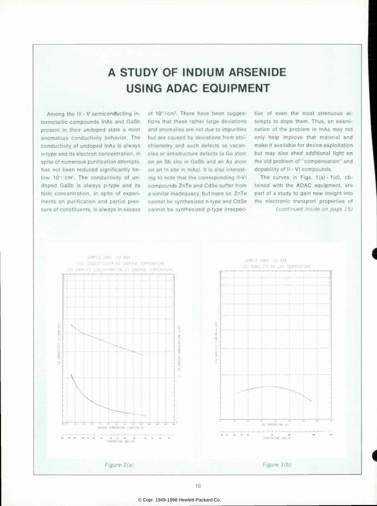
I n A s . F i g . 1 ( a ) s h o w s a c o m p u t e r - g e n e r a t e d p l o t o f c o n d u c t i v i t y a n d c a r r i e r c o n c e n t r a t i o n o n l o g a r i t h m i c s c a l e s v s . i nve rse abso lu te t empera tu re , o f an un - d o p e d I n A s s a m p l e f r o m M o n s a n t o i n go t C2 494 . The upper cu rve rep resen ts t h e c o n d u c t i v i t y , w h i c h d e c r e a s e s f r o m 2 6 m h o / c m a t 2 9 5 Â ° K t o 2 8 m h o / c m a t 8 0 Â ° K . T h e l o w e r c u r v e i n d i c a t e s t h e c h a n g e i n f r e e e l e c t r o n c o n c e n t r a t i o n o v e r t h e s a m e r a n g e . T h i s d r o p s f r o m 2 . 1 x 1 0 " / c m M o 1 . 1 x 1 0 " / c m ! .
F i g . 1 ( b ) i s t h e c o m p u t e r - g e n e r a t e d g r a p h o f t h e c a l c u l a t e d m o b i l i t y v s . a b so l u te t empe ra tu re , bo th on l oga r i t hm ic s c a l e s . T h e s e p l o t s a r e u s e f u l t o d e t e r m i n e a c t i v a t i o n e n e r g i e s d i r e c t l y f r o m
t h e s l o p e s o f g r a p h 1 ( a ) o r s c a t t e r i n g m e c h a n i s m s f r o m t h e s l o p e s o f 1 ( b ) . T h e m o b i l i t y i s n e a r l y c o n s t a n t h a v i n g a v a l u e o f a b o u t 1 5 , 0 0 0 c m V V s w i t h a s l i gh t max imum a t abou t 140°K.
F igs . 1 (c ) and 1 (d ) a re p lo ts i den t i ca l t o t h o s e s e e n i n F i g s . 1 ( a ) a n d 1 ( b ) e x c e p t t h a t t h e I n A s m a t e r i a l h a s u n d e r g o n e a d i f f u s i o n w i t h g o l d . ( T h e r e a r e no p rev ious repo r t s o f such a t r ea tmen t i n t he l i t e ra tu re . ) I n F ig . 1 ( c ) , t he l ower c u r v e i s t h e c o n d u c t i v i t y c u r v e . W h i l e a p r o n o u n c e d c h a n g e h a s t a k e n p l a c e i n t h e c o n d u c t i v i t y a n d m o b i l i t y , a s s h o w n i n F i g . 1 ( d ) , o n l y a s m a l l m o d i f i c a t i o n i n t h e f r e e e l e c t r o n c o n c e n t r a t i o n h a s t a k e n p l a c e . N o t e t h a t t h e t e m p e r a t u r e p l o t s , b e c a u s e o f c u r v a t u r e s a n d i n f l e c t i o n p o i n t s , c o n t a i n m u c h m o r e i n f o r m a t i o n a b o u t t h e s a m p l e s t h a n c a n b e o b t a i n e d f r o m m e a s u r e
m e n t s a t j u s t o n e o r t w o t e m p e r a t u r e s . Wh i l e t he s tudy o f n - t ype I nAs i s s t i l l
i n i t s b e g i n n i n g , t h e i n i t i a l r e s u l t s a p p e a r c o n s i s t e n t w i t h t h e e a r l i e r r e p o r t s o f t h e c o n d u c t i v i t y a n o m a l y . T h e o r i g i n o f t h e o b s e r v e d m o b i l i t y d e c r e a s e r e s u l t i n g f r o m g o l d d i f f u s i o n h a s n o t y e t b e e n u n i q u e l y d e t e r m i n e d , b u t e x a m i n a t i o n o f t h e m a t e r i a l w i l l b e m a d e f o r e v i d e n c e o f g o l d p r e c i p i t a t e s a n d o t h e r p o s s i b l e c a u s e s o f i n c r e a s e d e l e c t r o n s c a t t e r i n g . I t i s h o p e d t h a t t h e g r e a t f l e x i b i l i t y i n p r o g r a m m i n g o f d a t a a c q u i s i t i o n o f f e r e d b y A D A C , c o m b i n e d w i t h c o m p u t e r i z e d d a t a r e d u c t i o n a n d p l o t t i n g w i l l e n a b l e t a c k l i n g a n d s o l v i n g p r o b l e m s w h i c h o t h e r w i s e w o u l d b e t o o t i m e - c o n s u m i n g .
T h e s a m p l e p r e p a r a t i o n s a n d g o l d d i f f u s i o n s w e r e c a r r i e d o u t b y D z i d r a S a m s o n o v s o f t h e - h p - L a b o r a t o r i e s .
SflMPLE INRS C2 494GOLD
LOG CONDUCTIVITY VS INVERSE TEMPERHTURE
LOG CHRRIER CONCENTRHTION VS INVERSE TEMPERHTURE
SflMPLE INRS C2 494GOLO
LOG MOBILITY VS LOG TEMPERHTURE
I N V E R S E T E W P E R f l T U R E [ 1 D O G / D E G K Ã L O G T E W C T f l T U R E [ K ]
T E r * - E R f i T U R E C O E D K l T E H P E R f l T U R E [ D E C K ]
Figure 1 (c ) F igure 1 (d)
© Copr. 1949-1998 Hewlett-Packard Co.
A S T U D Y O F I N D I U M A R S E N I D E U S I N G A D A C E Q U I P M E N T
A m o n g t h e I I I - V s e m i c o n d u c t i n g  ¡ n - t e r m e t a l l i c c o m p o u n d s I n A s a n d G a S b p r e s e n t i n t h e i r u n d o p e d s t a t e a m o s t a n o m a l o u s c o n d u c t i v i t y b e h a v i o r . T h e c o n d u c t i v i t y o f u n d o p e d I n A s i s a l w a y s n - t ype and i t s e lec t ron concen t ra t i on , i n sp i t e o f numerous pu r i f i ca t i on a t t emp ts , h a s n o t b e e n r e d u c e d s i g n i f i c a n t l y b e l o w 1 0 " ' c m ' . T h e c o n d u c t i v i t y o f u n d o p e d G a S b i s a l w a y s p - t y p e a n d i t s h o l e c o n c e n t r a t i o n , i n s p i t e o f e x p e r i m e n t s o n p u r i f i c a t i o n a n d p a r t i a l p r e s su re o f cons t i tuen ts , i s a lways in excess
o f 1 0 " / c m 3 . T h e r e h a v e b e e n s u g g e s t i o n s t h a t t h e s e r a t h e r l a r g e d e v i a t i o n s and anoma l i es a re no t due to impur i t i es b u t a r e c a u s e d b y d e v i a t i o n s f r o m s t o i - c h i o m e t r y a n d s u c h d e f e c t s a s v a c a n c ies o r an t i s t ruc tu re de fec ts (a Ga a tom o n a n S b s i t e i n G a S b a n d a n A s a t o m on an I n s i t e i n I nAs ) . I t i s a l so i n te res t i n g t o n o t e t h a t t h e c o r r e s p o n d i n g I I - V I c o m p o u n d s Z n T e a n d C d S e s u f f e r f r o m a s im i l a r i nadequacy , bu t more so . ZnTe canno t be syn thes i zed n - t ype and CdSe c a n n o t b e s y n t h e s i z e d p - t y p e i r r e s p e c
t i v e o f e v e n t h e m o s t s t r e n u o u s a t t e m p t s t o d o p e t h e m . T h u s , a n e x a m i n a t i o n o f t h e p r o b l e m i n I n A s m a y n o t o n l y h e l p i m p r o v e t h a t m a t e r i a l a n d make i t ava i l ab le fo r dev ice exp lo i ta t i on b u t m a y a l s o s h e d a d d i t i o n a l l i g h t o n t h e o l d p r o b l e m o f " c o m p e n s a t i o n " a n d dopab i l i t y o f I I - V I compounds .
T h e c u r v e s i n F i g s . 1 ( a ) - 1 ( d ) , o b t a i n e d w i t h t h e A D A C e q u i p m e n t , a r e p a r t o f a s t u d y t o g a i n n e w i n s i g h t i n t o t h e e l e c t r o n i c t r a n s p o r t p r o p e r t i e s o f
( c o n t i n u e d i n s i d e o n p a g e 1 5 )
S R M P L E I N f l S
LOG CONC
L O G C f l R R I E R C I
TEMPERRTURE
B S E T E M P E R H T U R E
S f l M P L E I N R S C 2 4 9 4
L O G M O B I L I T Y V S L O G T E M P E R B T U R E
,
I N V E R S E T E M P E f l f l T U R E [ 1 0 0 0 / D E G 1 0 L O G T E M P E f W T W C [ Â «
T E f F E W I T U R E [ D E C ( O ' E M P E f t f l T U R E C D E G I Ã “
Figure l (a ) Figure 1 (b)
'•
© Copr. 1949-1998 Hewlett-Packard Co.