1957 chevy installation manual revision 010615 chevy... · revised: january 6, 2015 page 4 mounting...
TRANSCRIPT

Classic Instruments
1957 Chevy
Installation Manual

Revised:January6,2015 Page2
TableofContentsWelcome from the Team at Classic Instruments! .............................................................................................................. 3
Mounting Gauges ............................................................................................................................................................... 4
Speedo, Tach, Volt and Oil Pressure Gauge Wiring .......................................................................................................... 5
Speedo, Tach, Volt and Oil Pressure Gauge Wiring Diagram ......................................................................................................... 6
Temperature Gauge Wiring ................................................................................................................................................ 7
Temperature Gauge Wiring Diagram ............................................................................................................................................. 7
Fuel Gauge Wiring ............................................................................................................................................................. 8
Fuel Gauge Wiring Diagram ............................................................................................................................................................ 8
Pulse Signal Generator [SN16] Wiring .............................................................................................................................. 8
Oil Pressure Sender Installation ......................................................................................................................................... 9
Temperature Sender Installation ...................................................................................................................................... 10
Clock (optional) Wiring ................................................................................................................................................... 11
Clock Wiring Diagram ................................................................................................................................................................... 11
Speedometer & Tachometer Calibration .......................................................................................................................... 12
Entering Calibration Mode: .......................................................................................................................................................... 12
Tachometer Cylinder Setup: ......................................................................................................................................................... 12
Tachometer Signal Type Setup: .................................................................................................................................................... 13
Speedometer “Instant” Calibration: .............................................................................................................................................. 13
Speedometer “Real-Time” Calibration: ........................................................................................................................................ 14
Speedometer “Measured Mile” Calibration: ................................................................................................................................. 14
Optional Shift Indicator Setup: ..................................................................................................................................................... 15
Reset Gauge Calibration to Factory Defaults: .............................................................................................................................. 15
Revised:January6,2015 Page3
Welcome from the Team at Classic Instruments! Our congratulations and appreciation for your purchase of one of the finest quality sets of specialty instruments
ever produced! Your instrument set has been conceived, designed, and manufactured by Classic Instruments, Inc. in the U.S.A. Each instrument has been tested and certified for accuracy and quality before packaging and shipping.
For trouble-free installation and operation follow the instructions exactly as outlined. Your instruments were assembled to precise specifications and although each has a seven (7) year warranty covering defective parts and workmanship – this warranty will not cover instruments or sender units which have been installed incorrectly.
Follow our recommended procedures for installation and proper hookup to maintain the value and appearance of your instrument set during many future years of accurate and dependable service!
LIMITED WARRANTY
Classic Instruments, Inc. (CI) warrants to the original purchaser that any CI product manufactured or supplied by CI will be free from defects in material and workmanship under normal use and service for a period of seven (7) years from date of purchase.
Improper installation, use of sending units other than CI’s or attempted repair or adjustments by other than CI shall void this warranty. Disassembly of any instruments or senders for whatever reason shall specifically void this warranty.
It’s always easy to look to a part for an issue with your set. Before you conclude that a part may be bad, thoroughly check your work. Today’s semiconductors and passive components have reached incredibly high reliability levels, but there is still room for error in our human construction skills. However, on rare occasions a sour part can slip through. Please be aware that testing can usually determine if the part was truly defective or damaged by assembly or usage. Don’t be afraid of telling us that you “blew it”, we’re all human and in most cases, replacement parts are very reasonably priced.
Purchaser requesting a product to be repaired or replaced under warranty must first call CI at 1-800-575-0461 before the return of defective part. Send defective part to 826 Moll Drive, Boyne City, MI 49712, USA. Include a written description of the failure with defective part.
Purchaser agrees and accepts that under no circumstances will a warranty replacement be furnished until CI has first received, inspected, and tested the returned part.
All other warranties expressed or implied are hereby excluded including any implied warranty of merchandise and implied warranty of fitness for a particular purpose. The sole and exclusive remedy for breach of this warranty is limited to the replacement set forth above.
It is expressly agreed that there shall be no further remedy for consequential or other type of damage, including any claim for loss of profit, engine damage or injury.
TECHNICAL ASSISTANCE 1-800-575-0461
OR Visit our website for the latest in gauge design and updates to our installation manual
www.classicinstruments.com
Revised:January6,2015 Page4
Mounting Gauges
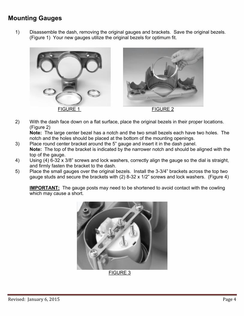
1) Disassemble the dash, removing the original gauges and brackets. Save the original bezels. (Figure 1) Your new gauges utilize the original bezels for optimum fit.
FIGURE 1 FIGURE 2
2) With the dash face down on a flat surface, place the original bezels in their proper locations. (Figure 2) Note: The large center bezel has a notch and the two small bezels each have two holes. The notch and the holes should be placed at the bottom of the mounting openings.
3) Place round center bracket around the 5” gauge and insert it in the dash panel. Note: The top of the bracket is indicated by the narrower notch and should be aligned with the top of the gauge.
4) Using (4) 6-32 x 3/8” screws and lock washers, correctly align the gauge so the dial is straight, and firmly fasten the bracket to the dash.
5) Place the small gauges over the original bezels. Install the 3-3/4” brackets across the top two gauge studs and secure the brackets with (2) 8-32 x 1/2” screws and lock washers. (Figure 4) IMPORTANT: The gauge posts may need to be shortened to avoid contact with the cowling which may cause a short.
FIGURE 3

Revised:January6,2015 Page5
Speedo, Tach, Volt and Oil Pressure Gauge Wiring
1) Always disconnect the vehicle battery before wiring any gauge. 2) Connect a switched +12VDC power source to the PINK wire of the gauge cluster wire harness.
We recommend using a dedicated power source to avoid possible problems caused by bad “noisy” power.
3) Connect a good chassis ground to the BLACK wire of the gauge cluster wire harness. We recommend using a dedicated chassis ground (not stacked with other ground wires) to avoid possible problems caused by a bad ground.
4) Connect a speed signal from one of the following sources to the PURPLE wire of the gauge cluster wire harness: a. White signal wire from a pulse signal generator [SN16]
i. See “Pulse Signal Generator Wiring” section for complete SN16 wiring instructions. [OR] b. One wire (either one will work) from an electronic vehicle speed sensor (VSS) that is NOT
going to be connected to the vehicle computer. (This is the option for many Tremec and 700R4 transmissions.)
i. Connect the other wire of the VSS to the same ground point as the BLACK wire from step 3.
[OR] c. Speed signal wire from the vehicle computer. (This is usually a green wire in GM LS engine
harnesses.) 5) Connect the RED wire of the gauge cluster wire harness to the Red wire of a SN16 pulse signal
generator. DO NOT USE the Red wire if a SN16 is not being used. (it does not require power)
6) Connect a tachometer signal to the WHITE wire of the gauge cluster wire harness. a. STANDARD POINTS & CONDENSER SYSTEM
i. Connect to the negative side of the coil (usually marked as “-“). b. GMC – HEI (High Energy Ignition System)
i. Connect to the “TACH” terminal on coil side of distributor cap. c. MSD (Multiple Spark Discharge System)
i. Connect to the TACH signal from the MSD box. d. VERTEX MAGNETO SYSTEM
i. Connect to the “KILL” terminal on the side of a Vertex magneto body. An external adapter such as an MSD “Pro Mag Tach Converter” #8132 may be required.
e. ACCEL IGNITION COILS i. Connect to the negative side of the coil. CAUTION! Some Accel ignition coils require the tach signal
wire to be connected to the “+” terminal on the coil! PLEASE carefully read Accel’s instructions before connecting ignition coil.
f. MALLORY IGNITION i. Connect to the negative terminal side of coil (usually marked as “-“).
g. PCM TACHOMETER SIGNAL i. Connect to the signal from the computer. The tachometer typically needs to be set on 4 cylinder setting.
h. MULTIPLE COIL IGNITION SYSTEMS i. A tach adapter may be required for these ignition systems. A tach signal driver such as the MSD #8913,
which produces a 12V square wave signal, is recommended. Please check with manufacturer for your specific application.
i. NOTICE! For all other ignition systems please look at the owner’s manual for that system.
7) Connect the oil pressure sender to the BLUE wire of the gauge cluster wire harness. 8) Connect high beam indicator power to the GREEN wire of the gauge cluster wire harness. 9) Connect dash light power to the GREY wire of the gauge cluster wire harness.

Revised:January6,2015 Page6
10) Connect either wire of the momentary contact setup pushbutton to the BROWN wire of the gauge cluster wire harness. a. Connect the other wire of the pushbutton to ground.
11) Optional Connection (must be special ordered): Connect left turn indicator power to the BLUE / WHITE wire of the gauge cluster wire harness.
12) Optional connection (must be special ordered): Connect right turn indicator power to the PURPLE / WHITE wire of the gauge cluster wire harness.
13) The YELLOW wire of the gauge cluster wire harness is NOT USED.
Speedo, Tach, Volt and Oil Pressure Gauge Wiring Diagram
High
Be
am Ind
icator [G
RE
EN
]
Go
od C
hassis G
roun
d [B
LAC
K]
Option
al Left Turn
Indica
tor [B
LU
E / W
HIT
E]
Spee
dom
eter S
ignal [P
UR
PLE
]
Dash
Light P
ow
er [GR
EY
]
Filte
red P
ower O
utput to
SN
16 (if e
quip
ped) [R
ED
]
Setu
p B
utton C
onnectio
n [BR
OW
N]
Option
al Rig
ht Turn
Indicator [P
UR
PL
E / W
HIT
E]
Oil P
ressu
re Sig
nal [B
LU
E]
Ta
chom
eter S
ignal [W
HIT
E]
No
t Use
d [Y
ELLO
W]
+12
VD
C S
witch
ed P
ower [P
INK
]
+
AC
C

Revised:January6,2015 Page7
Temperature Gauge Wiring
1) Always disconnect the vehicle battery before wiring any gauge. 2) Connect a switched +12VDC power source to the post marked “I” on the back of the temperature
gauge. 3) Connect a good chassis ground to the post marked “G” on the back of the temperature gauge.
This post also has the bracket which holds the gauge in the dash over it. 4) Connect the temperature sender to the post marked “S” on the back of the temperature gauge. 5) Connect dash light power to the spade terminal marked “L” on the back of the temperature
gauge.
Temperature Gauge Wiring Diagram
Ground
+12VDC switched
Dash Light Power
GO
L
S I
Signal WireLock Washer
Nut
Washer
Ring Terminal
Intake ManifoldTemperature Sender
Do not use teflon tape on the threads ofthe sender since this interferes with thesender's ground connection
Part Numbers:SN25, SN24,SN23 or SN22

Revised:January6,2015 Page8
Fuel Gauge Wiring
1) Always disconnect the vehicle battery before wiring any gauge. 2) Connect a switched +12VDC power source to the post marked “I” on the back of the temperature
gauge. 3) Connect a good chassis ground to the post marked “G” on the back of the temperature gauge.
This post also has the bracket which holds the gauge in the dash over it. 4) Connect the temperature sender to the post marked “S” on the back of the temperature gauge. 5) Connect dash light power to the spade terminal marked “L” on the back of the temperature
gauge.
Fuel Gauge Wiring Diagram
Ground
+12VDC switched
Dash Light Power
GO
L
S I
Signal Wire
Fuel Level SenderGround
Pulse Signal Generator [SN16] Wiring
Attach the signal generator to the transmission speedometer gear housing (where the speedometer cable originally connected). Do not use excessive force to tighten. These signal generators produce approximately 16,000 pulses per mile (PPM).
Red
Black
White
Red: ---------- +12VDC Black: -------- Ground White:-------- Signal
Revised:January6,2015 Page9
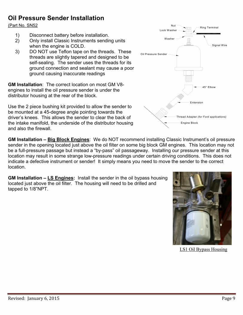
Oil Pressure Sender Installation (Part No. SN52
1) Disconnect battery before installation. 2) Only install Classic Instruments sending units
when the engine is COLD. 3) DO NOT use Teflon tape on the threads. These
threads are slightly tapered and designed to be self-sealing. The sender uses the threads for its ground connection and sealant may cause a poor ground causing inaccurate readings
GM Installation: The correct location on most GM V8-engines to install the oil pressure sender is under the distributor housing at the rear of the block. Use the 2 piece bushing kit provided to allow the sender to be mounted at a 45-degree angle pointing towards the driver’s knees. This allows the sender to clear the back of the intake manifold, the underside of the distributor housing and also the firewall. GM Installation – Big Block Engines: We do NOT recommend installing Classic Instrument’s oil pressure sender in the opening located just above the oil filter on some big block GM engines. This location may not be a full-pressure passage but instead a “by-pass” oil passageway. Installing our pressure sender at this location may result in some strange low-pressure readings under certain driving conditions. This does not indicate a defective instrument or sender! It simply means you need to move the sender to the correct location. GM Installation – LS Engines: Install the sender in the oil bypass housing located just above the oil filter. The housing will need to be drilled and tapped to 1/8”NPT. LS1 Oil Bypass Housing
Nut
Lock Washer
Washer
Signal Wire
Oil Pressure Sender
Ring Terminal
45° Elbow
Entension
Thread Adapter (for Ford applications)
Engine Block
Revised:January6,2015 Page10
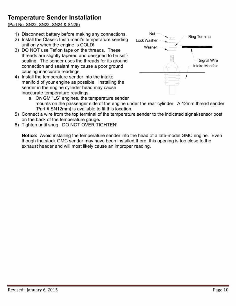
Temperature Sender Installation (Part No. SN22, SN23, SN24 & SN25)
1) Disconnect battery before making any connections. 2) Install the Classic Instrument’s temperature sending
unit only when the engine is COLD! 3) DO NOT use Teflon tape on the threads. These
threads are slightly tapered and designed to be self-sealing. The sender uses the threads for its ground connection and sealant may cause a poor ground causing inaccurate readings
4) Install the temperature sender into the intake manifold of your engine as possible. Installing the sender in the engine cylinder head may cause inaccurate temperature readings.
a. On GM “LS” engines, the temperature sender mounts on the passenger side of the engine under the rear cylinder. A 12mm thread sender [Part # SN12mm] is available to fit this location.
5) Connect a wire from the top terminal of the temperature sender to the indicated signal/sensor post on the back of the temperature gauge.
6) Tighten until snug. DO NOT OVER TIGHTEN!
Notice: Avoid installing the temperature sender into the head of a late-model GMC engine. Even though the stock GMC sender may have been installed there, this opening is too close to the exhaust header and will most likely cause an improper reading.
Signal Wire
Lock Washer
Nut
Washer
Ring Terminal
Intake Manifold
Revised:January6,2015 Page11
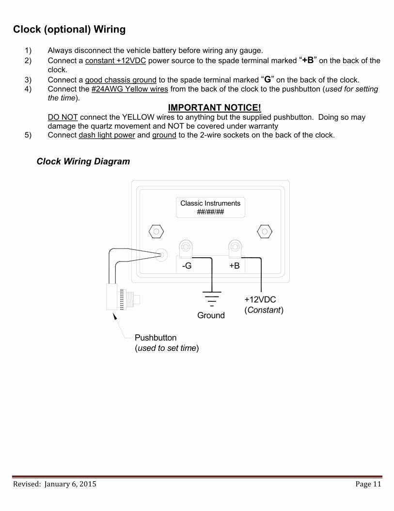
Clock (optional) Wiring
1) Always disconnect the vehicle battery before wiring any gauge. 2) Connect a constant +12VDC power source to the spade terminal marked “+B” on the back of the
clock. 3) Connect a good chassis ground to the spade terminal marked “G” on the back of the clock. 4) Connect the #24AWG Yellow wires from the back of the clock to the pushbutton (used for setting
the time). IMPORTANT NOTICE!
DO NOT connect the YELLOW wires to anything but the supplied pushbutton. Doing so may damage the quartz movement and NOT be covered under warranty
5) Connect dash light power and ground to the 2-wire sockets on the back of the clock.
Clock Wiring Diagram
-G +B
Classic Instruments##/##/##
+12VDC(Constant)
Ground
Pushbutton(used to set time)
Revised:January6,2015 Page12
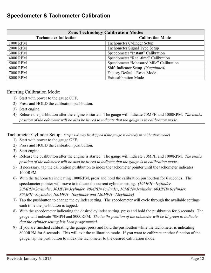
Speedometer & Tachometer Calibration
Zeus Technology Calibration Modes
Tachometer Indication Calibration Mode 1000 RPM Tachometer Cylinder Setup 2000 RPM Tachometer Signal Type Setup 3000 RPM Speedometer “Instant” Calibration 4000 RPM Speedometer “Real-time” Calibration 5000 RPM Speedometer “Measured Mile” Calibration 6000 RPM Shift Indicator Setup (if equipped) 7000 RPM Factory Defaults Reset Mode 8000 RPM Exit calibration Mode
Entering Calibration Mode: 1) Start with power to the gauge OFF. 2) Press and HOLD the calibration pushbutton. 3) Start engine. 4) Release the pushbutton after the engine is started. The gauge will indicate 70MPH and 1000RPM. The tenths
position of the odometer will be also be lit red to indicate that the gauge is in calibration mode.
Tachometer Cylinder Setup: (steps 1-4 may be skipped if the gauge is already in calibration mode)
1) Start with power to the gauge OFF. 2) Press and HOLD the calibration pushbutton. 3) Start engine. 4) Release the pushbutton after the engine is started. The gauge will indicate 70MPH and 1000RPM. The tenths
position of the odometer will be also be lit red to indicate that the gauge is in calibration mode. 5) If necessary, tap the calibration pushbutton to index the tachometer pointer until the tachometer indicates
1000RPM. 6) With the tachometer indicating 1000RPM, press and hold the calibration pushbutton for 6 seconds. The
speedometer pointer will move to indicate the current cylinder setting. (10MPH=1cylinder, 20MPH=2cylinder, 30MPH=3cylinder, 40MPH=4cylinder, 50MPH=5cylinder, 60MPH=6cylinder, 80MPH=8cylinder, 100MPH=10cylinder and 120MPH=12cylinder)
7) Tap the pushbutton to change the cylinder setting. The speedometer will cycle through the available settings each time the pushbutton is tapped.
8) With the speedometer indicating the desired cylinder setting, press and hold the pushbutton for 6 seconds. The gauge will indicate 70MPH and 8000RPM. The tenths position of the odometer will be lit green to indicate that the cylinder setting has been programmed.
9) If you are finished calibrating the gauge, press and hold the pushbutton while the tachometer is indicating 8000RPM for 6 seconds. This will exit the calibration mode. If you want to calibrate another function of the gauge, tap the pushbutton to index the tachometer to the desired calibration mode.

Revised:January6,2015 Page13
Tachometer Signal Type Setup: (steps 1-4 may be skipped if the gauge is already in calibration mode) 1) Start with power to the gauge OFF. 2) Press and HOLD the calibration pushbutton. 3) Start engine. 4) Release the pushbutton after the engine is started. The gauge will indicate 70MPH and 1000RPM. The tenths
position of the odometer will be also be lit red to indicate that the gauge is in calibration mode. 5) Tap the calibration pushbutton to index the tachometer pointer until the tachometer indicates 2000RPM. 6) With the tachometer indicating 2000RPM, press and hold the calibration pushbutton for 6 seconds. The
speedometer pointer will move to indicate the current signal type setting. The tenths position of the odometer will flash green and red.
7) Tap the pushbutton to change the signal type setting. The speedometer will cycle between the two options each time the pushbutton is tapped. (50MPH=5V Signal, 120MPH=12V Signal)
8) Set the signal type to 5V if using a computer generated tachometer signal. Set the signal type to 12V for all other tachometer signals.
9) With the speedometer indicating the desired signal type setting, press and hold the pushbutton for 6 seconds. The gauge will indicate 70MPH and 8000RPM. The tenths position of the odometer will be lit green to indicate that the signal type has been programmed.
10) If you are finished calibrating the gauge, press and hold the pushbutton while the tachometer is indicating 8000RPM for 6 seconds. This will exit the calibration mode. If you want to calibrate another function of the gauge, tap the pushbutton to index the tachometer to the desired calibration mode.
Speedometer “Instant” Calibration: (steps 1-4 may be skipped if the gauge is already in calibration mode)
1) Start with power to the gauge OFF. 2) Press and HOLD the calibration pushbutton. 3) Start engine. 4) Release the pushbutton after the engine is started. The gauge will indicate 70MPH and 1000RPM. The tenths
position of the odometer will be also be lit red to indicate that the gauge is in calibration mode. 5) Tap the calibration pushbutton to index the tachometer pointer until the tachometer indicates 3000RPM. 6) With the tachometer indicating 3000RPM, press and hold the calibration pushbutton for 6 seconds. The
speedometer pointer will move to 0MPH. The tenths position of the odometer will be flash green and red when a speed signal is detected. If no signal is detected, it will remain red.
7) Drive the vehicle at exactly 30MPH. Press and hold the pushbutton while traveling 30MPH. The tenths position of the odometer will be lit solid red or solid green while the button is pressed. When the calibration is completed, the speedometer will move to indicate 30MPH at which point the pushbutton may be released. The tenths position will also be lit green to indicate a successful calibration.
8) If you are satisfied with the speedometer calibration, tap the pushbutton once to get back into the main gauge calibration mode. The gauge will indicate 70MPH and 8000RPM. If you would like to re-do the calibration, simply press and hold the pushbutton while traveling 30MPH and hold the pushbutton until the speedometer indicates 30MPH at which point the pushbutton may be released.
9) When you are finished calibrating the gauge, tap the pushbutton and the gauge will indicate 70MPH and 8000RPM. Then, Press and old the pushbutton for 6 seconds. This will exit the calibration mode. If you want to calibrate another function of the gauge, tap the pushbutton to index the tachometer to the desired calibration mode.

Revised:January6,2015 Page14
Speedometer “Real-Time” Calibration: (steps 1-4 may be skipped if the gauge is already in calibration mode) 1) Start with power to the gauge OFF. 2) Press and HOLD the calibration pushbutton. 3) Start engine. 4) Release the pushbutton after the engine is started. The gauge will indicate 70MPH and 1000RPM. The tenths
position of the odometer will be also be lit red to indicate that the gauge is in calibration mode. 5) Tap the calibration pushbutton to index the tachometer pointer until the tachometer indicates 4000RPM. 6) With the tachometer indicating 4000RPM, press and hold the calibration pushbutton for 6 seconds. The
speedometer pointer will move to indicate the speed with the current calibration (which you will need to adjust to make correct).
7) Press and hold the pushbutton to increase the indicated speed. Release the pushbutton to stop increasing the speed. The tenths position of the odometer will flash green and red if a speed signal is detected. If no signal is detected, the tenths position of the odometer will be lit red.
8) If necessary, press and hold the pushbutton again to decrease the indicated speed. Release the pushbutton to stop decreasing.
9) Press and hold the pushbutton once more to increase the indicated speed. Etc… 10) Once the correct speed is dialed in on the speedometer, wait 10 seconds until the tenths position of the
odometer turns green and then tap the pushbutton. The gauge will indicate 70MPH and 8000RPM. 11) If you are finished calibrating the gauge, press and hold the pushbutton while the tachometer is indicating
8000RPM for 6 seconds. This will exit the calibration mode. If you want to calibrate another function of the gauge, tap the pushbutton to index the tachometer to the desired calibration mode.
Speedometer “Measured Mile” Calibration: (steps 1-4 may be skipped if the gauge is already in calibration mode)
1) Start with power to the gauge OFF. 2) Press and HOLD the calibration pushbutton. 3) Start engine. 4) Release the pushbutton after the engine is started. The gauge will indicate 70MPH and 1000RPM. The tenths
position of the odometer will be also be lit red to indicate that the gauge is in calibration mode. 5) Tap the calibration pushbutton to index the tachometer pointer until the tachometer indicates 5000RPM. 6) With the tachometer indicating 5000RPM, press and hold the pushbutton for 6 seconds. The speedometer
pointer will move to 30MPH. 7) Begin driving a measured mile. While driving, the tenths position of the odometer will be flashing green and
red to indicate a good speed signal. If no speed signal is detected, the tenths position of the odometer will be lit red.
8) At the end of your measured mile, press and hold the pushbutton for another 6 seconds. The gauge will indicate 70MPH and 8000RPM and the tenths position of the odometer will be lit green to indicate a successful calibration.
9) If you are finished calibrating the gauge, press and hold the pushbutton while the tachometer is indicating 8000RPM for 6 seconds. This will exit the calibration mode. If you want to calibrate another function of the gauge, tap the pushbutton to index the tachometer to the desired calibration mode.

Revised:January6,2015 Page15
Optional Shift Indicator Setup: (steps 1-4 may be skipped if the gauge is already in calibration mode) 1) Start with power to the gauge OFF. 2) Press and HOLD the calibration pushbutton. 3) Start engine. 4) Release the pushbutton after the engine is started. The gauge will indicate 70MPH and 1000RPM. The tenths
position of the odometer will be also be lit red to indicate that the gauge is in calibration mode. 5) Tap the calibration pushbutton to index the tachometer pointer until the tachometer indicates 6000RPM. 6) With the tachometer indicating 6000RPM, press and hold the pushbutton for 6 seconds. The tachometer
pointer will move to 0RPM and the tenths position of the odometer will flash green and red. The shift light trigger RPM can now be set.
7) Press and hold the pushbutton to increase the tachometer reading. Release the pushbutton to stop increasing the tachometer reading.
8) If necessary, push and hold the pushbutton again to decrease the tachometer reading. Release the pushbutton to stop decreasing the tachometer reading.
9) Press and hold the pushbutton once more to increase the tachometer reading. Etc… 10) When the desired shift light trigger RPM is indicated on the tachometer, release the pushbutton and wait 10
seconds. After 10 seconds of no pushbutton activity, the trigger point will be stored; the tachometer will indicate 8000RPM and the tenths position of the odometer will be lit green.
11) If you are finished calibrating the gauge, press and hold the pushbutton while the tachometer is indicating 8000RPM for 6 seconds. This will exit the calibration mode. If you want to calibrate another function of the gauge, tap the pushbutton to index the tachometer to the desired calibration mode.
Reset Gauge Calibration to Factory Defaults: (steps 1-4 may be skipped if the gauge is already in calibration mode)
1) Start with power to the gauge OFF. 2) Press and HOLD the calibration pushbutton. 3) Start engine. 4) Release the pushbutton after the engine is started. The gauge will indicate 70MPH and 1000RPM. The tenths
position of the odometer will be also be lit red to indicate that the gauge is in calibration mode. 5) Tap the calibration pushbutton to index the tachometer pointer until the tachometer indicates 7000RPM. 6) With the tachometer indicating 7000RPM, press and hold the pushbutton for 6 seconds. The tachometer will
move to 8000RPM and the tenths position of the odometer will be lit green to indicate the gauge has been restored to the factory default settings.
7) If you are finished calibrating the gauge, press and hold the pushbutton while the tachometer is indicating 8000RPM for 6 seconds. This will exit the calibration mode. If you want to calibrate another function of the gauge, tap the pushbutton to index the tachometer to the desired calibration mode.